Procedure. for. Installation. of the P/N & P/N Voice Alert Systems. Procedure IP 1 Rev. 1. Date
|
|
|
- Shawn Melton
- 6 years ago
- Views:
Transcription
1 Procedure for Installation of the P/N & P/N Voice Alert Systems Procedure IP 1 Rev. 1 Date Approved By Aircraft Components inc Harbor Lake Dr. Safety Harbor FL I. Introduction Most general aviation aircraft were designed during a time when few pilots wore headsets. On these aircraft"> Procedure for Installation of the P/N & P/N Voice Alert Systems Procedure IP 1 Rev. 1 Date Approved By Aircraft Components inc Harbor Lake Dr. Safety Harbor FL /14
2 I. Introduction Most general aviation aircraft were designed during a time when few pilots wore headsets. On these aircraft, the stall and gear warning annunciators were placed in the cockpit, where they would be heard by the pilot. Today most pilots wear headsets, including the new active noise reduction headsets, designed to cut out the cockpit sounds. These innovations make it more difficult for the pilot to hear the warning horns. The Voice Alert system is an electronic device which detects the activation of the existing aircraft stall and/or gear warning annunciators, and responds by placing an instantly recognizable voice warning directly in the pilots headset, and through a built in speaker. The voice warnings provide the pilot with instant recognition of the unsafe conditions. Separate voice messages are used for the stall warning, and the gear warning, to promote instant recognition. The Voice Alert is a stand alone system. The Voice Alert does not affect the operation of the existing aircraft warning systems in any way. The Voice Alert is available for installation in both fixed and retractable gear aircraft. II. Installation Information Read the material in this manual to become familiar with the installation and the work involved before starting. This work must meet the requirements of the applicable sections of AC B The following table defines the applicable sections of this manual that apply to the installation in various aircraft makes and models. Refer to the AML list referenced by the STC for a listing of the current approved make and model aircraft. Manual Gear Aircraft Make and Model Manual Section Raytheon Aircraft Co. 19A, B19, M19A, 23, A23, A23A, A23 19, A23 24, III A B23, C23, A24, The Cessna Aircraft Co. 172, 172A, 172B, 172C, 172D, 172E, 172F, 172G, 172H, 172I, 172K, 172L, 172M, 172N, 172P, 172Q, 172R See Note 2 182, 182A, 182B, 182C, 182D, 182E, 182F, 182G, 182H, 182J, 182K, 182L, 182M, 182N, 182P, 182Q, 182R, 182S, 175, 175A, 175B, 175C, P172D, 185, 185A, 185B, 185C, 185D, 185E, A185E, A185F 180A, 180B, 180C, 180D, 180E, 180F, 180G, 180H, 180J, 180K 177, 177A, 177B 207, 207A, T207, T207A 208, 208A, 208B 206, P206, P206A, P206B, P206C, P206D, P206E, TP206A, TP206B, TP206C, TP206D, TP206E, U206, U206A, U206B, U206C, U206D, U206E, U206F, U206G,TU206A, TU206B, TU206C, TU206D, TU206E, TU206F, TU206G, 206H Tiger Aircraft LLC AA 5, AA 5A, AA 5B, AG 5B 111 AA 1, AA 1A, AA 1B, AA 1C Maul Aerospace BEE DEE, M 4, M 4C, M 4S, M 4T, M 4 180C, M 4 180S, M 4 180T, M 4 210, M 4 210C, M 4 210S, M 4 210T, M 4 220, M 4 220C, M 4 220S, M 4 220T, M 5 180C, M 5 200, M 5 210C, M 5 210TC, M 5 220C, M 5 235C, M 6 180, M 6 235, M 7 235, MX 7 235, MX 7 180, MX 7 420, MXT 7 180, MT 7 235, M 8 235, MX MXT 7 160, MX 7 180A, MXT 7 180A, MX 7 180B, MXT 7 420, M 7 235B, M 7 235A, M 7 235C, MX 7 180C III A III A III A The New Piper Aircraft PA , PA , PA , PA , PA , III A PA PA , PA PA 28S 160, PA 28S 180, PA T, PA Retractable Gear Aircraft Raytheon Aircraft Co. 50, B50, C50, D50, D50A, D50B, D50C, D50E, D50E 5990 E50, F50, G50,H50, J50 Raytheon Aircraft Co. A24R, B24R, C24R III C Raytheon Aircraft Co. 58P, 58PA, 58TC, 58TCA See Note 1 Raytheon Aircraft Co , 35 A33, 35 B33, 35 C33, 35 C33A, E33, E33A, See Note 1 E33C, F33, F33A, F33C, G33, H35, J35, K35, M35, N35, P35, S35, V35, V35A, V35B, 36, A36, A36TC, B36TC Raytheon Aircraft Co. B95A, D95A, E95, 95 55, 95 A55, 95 B55, 95 B55A, See Note 1 95 B55B, 95 B55A, 95 B55B, 95 C55, 95 C55A, D55, D55A, E55, E55A, 56TC, A56TC, 58, 58A, 95, B95 2/14
3 Raytheon Aircraft Co. 35, A35, B35, C35, D35, E35, F35, G35, 35R See Note 1 Raytheon Aircraft Co. 65, A65, A , 65 80, 65 A80, 65 B80, 65 88, 65 90, See Note 1 65 A90, 70, B90, C90, C90A, E90, H90, 100, A100, A100A A100C, B100, 200, 200C, 200CT, A200, A200C, B200, B200C, B200CT, B200T, 200T, A200CT, 99, 99A, A99, A99A, B99, C99 Bellanca inc , , , A, 17 30, 17 31, 17 31TC See Note 1 The Cessna Aircraft Co. R182, TR182 Retractable III D The Cessna Aircraft Co. 210, 210A, 210B, 210C, 210D, 210E, 210F, T210F, 210G, 210H, T210H, 210J, T210J, 210K, T210K, 210L, T210L, 210M, T210M, 210N, P210N, T210N, 210R, P210R, T210R, 210 5, 210 5A The Cessna Aircraft Co. 177RG III D III D The Cessna Aircraft Co. 310, 310A, 310B, 310C, 310D, 310E, 310F, 310G, 310H, See Note 1 310H, 310I, 310J, 310K, 310L, 310N, 310P, T310P, 310Q, T310Q, 310R, T310R The Cessna Aircraft Co. 320, 320 1, 320A, 320B, 320C, 320D, 320E, 320F, 335, 340, 340A The Cessna Aircraft Co. 337, 337A, 337B, T337B, 337C, T337C, 337D, T337D, 337E, T337E, 337F, T337F, 337G, T337G, 337H, P337H, T337H The Cessna Aircraft Co. 401, 401A, 401B, 402, 402A, 402B, 402C, 411, 411A, 414, 414A, 421, 421A, 421B, 421C, 425 III D III C Commander Aircraft 112, 114, 112TC, 112B, 112TCA, 114A, 114B, 114TC See Note 1 Corp Mooney Aircraft Corp M 20, M 20A, M 20B, M 20C, M 20D, M 20E, M 20F, M 20G, M 20J, M 20K, M 20L, M 20M, M 20R, M 20S The New Piper Aircraft PA 24, PA , PA , PA The New Piper Aircraft PA 28R 180, PA 28R 200, PA T, PA 28RT 201T, PA 28RT 201 The New Piper Aircraft PA , PA T The New Piper Aircraft PA 30, PA 39, PA 40 The New Piper Aircraft PA 31, PA , PA , PA The New Piper Aircraft PA , PA , PA 32S 300, PA 32R 300, PA 32RT 300, PA 32RT 300T, PA 32R 301, PA 32R 301T, PA , PA T The New Piper Aircraft PA , PA t, PA T The New Piper Aircraft PA 23, PA , PA , PA The New Piper Aircraft PA 31P, PA 31T, PA 31T1, PA 31T2, PA 31T3, PA 31P 350 Aerostar Aircraft Co. PA , PA , PA P, PA P, PA P III C III C Twin Commander 560 F, 680, 680 E, 680 F, 720, 680FL, 680T, 680V, See Note 1 Aircraft 680 W, 681, 690, 685, 690A, 690B, 690C, 690D, 695, 695A, 695B Twin Commander 500, 500A, 500 B, 500 U, 520, 560, 560 A, 560 E, 500 S See Note 1 Aircraft Note 1: These aircraft used various wiring configurations for activating the landing gear warning horn. It will be necessary to review the wiring schematic for the actual aircraft the installation is being performed on, and then perform the tests in section B and C to determine if installation Dwg. FIG B, C, or D applies. Note 2: Certain models of these aircraft use a pneumatic powered stall warning system instead of an electrically powered stall warning system.. The installation of the P/N 2040 system applies to those aircraft which have an electrically powered stall warning system only. 3/14
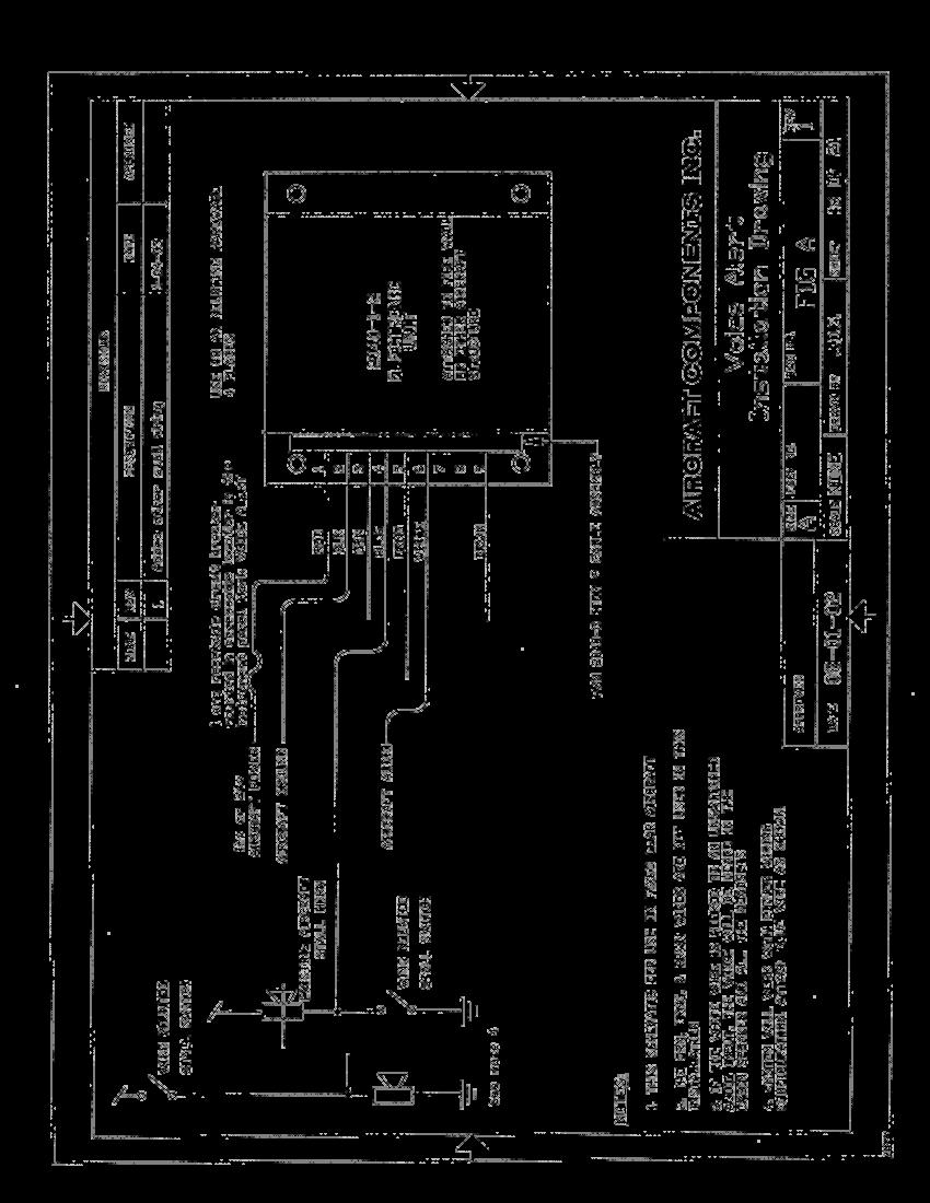
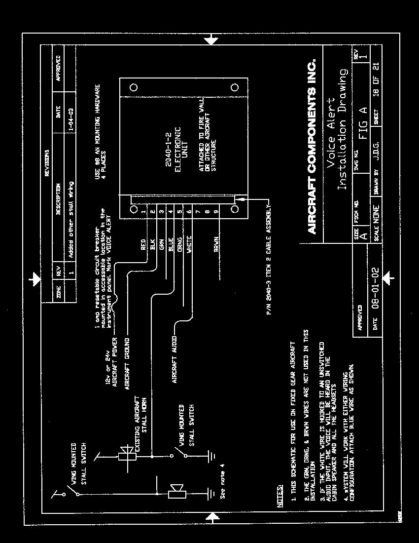
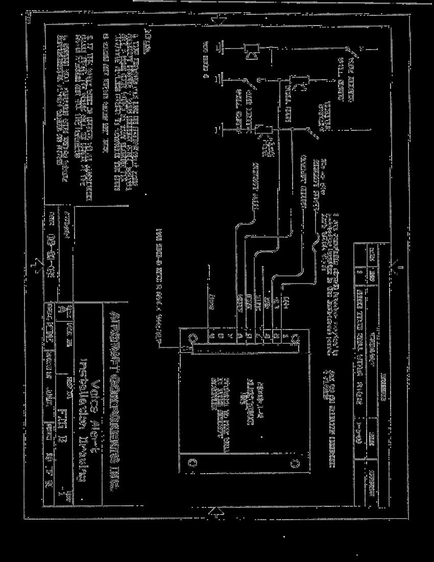
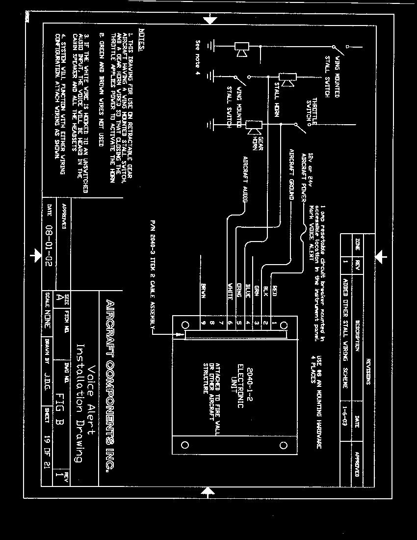
4 III. Installation Instructions The following sections provide specific detailed installation instructions for each aircraft make and model listed in the previous section. Section A, Installation in most fixed gear aircraft This section provides the instructions for installing the system in the approved fixed gear aircraft. This installation must use the P/N Voice Alert assembly. Note: Before starting the installation, activate the stall warning horn and mentally note the level of the horn volume. This will permit making a comparison of the horn volume after the installation to insure that it has not been effected by the installation of the Voice Alert system. 1. Select a location to firmly mount the Electronic Module to the aircraft. It can be mounted to the firewall, side panel, or other secondary aircraft structure. Do not alter, modify or drill any aircraft structural members when making this installation. Check to verify that the installation does not interfere with the aircraft controls or with other equipment. Do not mount the electronic module within 6 inches of other high current drawing electronic equipment. Any additional wire required for the installation should be #22 gauge or larger, and must meet the type defined in AC B chapter 11 section 7.Wiring should not be bundled with high current carrying conductors, coaxial antenna cables, or conductors carrying pulsed signals. Bundle and secure wiring. Refer to AC B sections through for information on bundling and securing wiring.. Drill 4 mounting holes as shown on Fig 1. Mount the Electronic Module as shown on FIG 2, using the hardware provided. 2. Wire the system as shown on installation drawing FIG A. using the cable assembly provided a) Attach the RED wire to the 12v or 24v power buss through a 1 circuit breaker using a ring connector provided. Note: The circuit breaker must be the resetable type and must be mounted within the pilot s reach to allow turning the system off in flight if required. Normal current draw is 150 ma. b) Attach the BLACK wire to a good aircraft ground point using a ring connector provided. The ground wire should be bolted to the aircraft structure using a machine screw and nut. Refer to AC B section for details on grounding electronic equipment. 3. Attach the WHITE wire to the aircraft audio system. The WHITE wire is a 600 ohm low level audio signal. This signal must be hooked to the aircraft audio system in a way, which prevents the pilot from accidentally turning it off. If the aircraft has an audio panel with an un switched audio input, the white wire should be attached directly to this un switched input so that the voice message will be heard directly through the cabin speaker and the headsets. If the aircraft does not have an un switched input, then the WHITE wire can be hooked directly into the pilot s headset jack. 4. Locate the stall horn in the aircraft. Using a meter, measure the voltage at the terminals on both sides of the stall horn when the horn is both sounding and silent. The voltage on one of the connections at the stall horn will change between aircraft voltage and ground as the horn activates. This is the terminal where the Voice Alert BLUE wire will connect. Connections can be made to the stall horn by using a ring connector if the horn has terminals, or by soldering or splicing into the existing wiring harness. Refer to AC B sections , , and for information on splicing and terminal installation. Refer to Installation drawing FIG B. The actual aircraft stall system may be wired in either configuration as shown on the drawing. 5. Cut the unused wires (GREEN, ORANGE, & BROWN) and secure against shorts. The unstripped cut ends can be doubled over and covered with a piece of the heat shrink tubing provided and secured in the wire bundle. Attach the cable to the electronic box. This completes the installation. Proceed to section IV for test of the system. Section B. Installation in Retractable Gear Aircraft that have the Landing Gear Warning horn grounded. Retarding the throttle then supplies power to cause the horn to sound. The following section provides specific detailed installation instructions for the retractable gear aircraft that reference Section. These aircraft have one side of the landing gear warning horn grounded. Retarding the throttle with the gear up applies power to the horn causing it to sound. Perform the following test to verify that Section is correct for your installation. Locate the landing gear warning horn in the aircraft. Many installations will have a single electrical connection and a ground wire at the horn. With the landing gear retracted, and the horn silent, measure the voltage at both of the gear horn connections. With this wiring configuration, both sides of the warning horn will read 0 volts when the horn is silent. Activate the horn, and re measure the voltage. One of the horn connections will now measure aircraft voltage, the other will measure ground. These voltage readings confirm that the installation will be made using installation Dwg. FIG B. The ORANGE wire in the cable assembly will attach to the horn connection that reads aircraft voltage when the horn is sounding. Refer to installation Dwg. FIG B. Note: Before starting the installation, activate the stall warning horn and the gear warning horn and mentally note the level of the horn volume. This test will allow a comparison of the horn volume after the Voice Alert installation to insure that the sound level has not been affected by the installation. This installation requires a P/N Voice Alert System. 1. Select a location to firmly mount the Electronic Module to the aircraft. It can be mounted to the 4/14
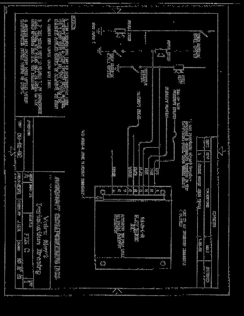
5 firewall, side panel, or other secondary aircraft structure. Do not alter, modify or drill any aircraft structural members when making this installation. Check to verify that the installation does not interfere with the aircraft controls or other equipment in the aircraft. Do not mount the electronic module within 6 inches of any high current drawing electronic equipment. Any additional wire required for the installation should be #22 gauge or greater, and meet the wire type defined in AC B Chapter 11, Section 7. Wiring should not be bundled with high current carrying conductors, coaxial antenna cables, or conductors carrying pulsed signals. Bundle and secure wiring. Refer to AC B sections through for information on bundling and securing wiring. Drill 4 mounting holes as shown on Fig 1. Mount the Electronic Module as shown on FIG 2, using the hardware provided. 2. Wire the system as shown on installation drawing FIG B. using the cable assembly provided a) Attach the RED wire to the 12v or 24v power buss through a 1 circuit breaker, using a ring connector provided. Note: The circuit breaker must be the resetable type and must be mounted within the pilot s reach to allow turning the system off in flight if required. Normal current draw is 150 ma. b) Attach the BLACK wire to a good aircraft ground point using a ring connector provided. The ground wire should be bolted to the aircraft structure using a machine screw and nut. Refer to AC B section for details on grounding electronic equipment 3. Attach the WHITE wire to the aircraft audio system. The WHITE wire is a 600 ohm low level audio signal. This signal must be hooked to the aircraft audio system in a way which prevents the pilot from accidentally turning it off. If the aircraft has an audio panel with an un switched audio input, the white wire should be attached directly to this un switched input so that the voice will be heard directly through the cabin speaker and the headsets. If the aircraft does not have an un switched input, then the WHITE wire can be hooked directly into the pilot s headset jack. 4. Locate the stall horn in the aircraft. Using a meter, measure the voltage at the terminals on both sides of the stall horn when the horn is both sounding and silent. The voltage on one of the connections at the stall horn will change between aircraft voltage and ground as the horn activates. This is the terminal where the Voice Alert BLUE wire will connect. Connections can be made to the stall horn by using a ring connector if the horn has terminals, or by soldering or splicing into the existing wiring harness. Refer to AC B sections , , and for information on splicing and terminal installation. Refer to Installation drawing FIG B. The actual aircraft stall system may be wired in either configuration as shown on the drawing 5. Attach the ORANGE wire to the correct side of the gear warning horn, as outlined above. Connections can be made to the gear horn using a ring connector if the horn has terminals, or by soldering or splicing into the existing wiring harness. Refer to AC B sections , , and for information on splicing and terminal installation..6. Cut the unused wires (GREEN, & BROWN) and secure against shorts. The unstripped cut ends can be doubled over and covered with a piece of the heat shrink tubing provided, and secured in the wire bundle. Attach the cable to the electronic box. This completes the installation. Proceed to section IV for test of the system. Section C. Installation in Retractable Gear Aircraft which have the landing gear warning system wired with power. Closing the throttle switch applies a ground, causing the horn to sound. The following section provides specific detailed installation instructions for the retractable gear aircraft listed in the previous section that referenced Section III C. These aircraft have a landing gear warning system wired with power supplied to the warning horn. Retarding the throttle supplies a ground causing the horn to sound. Perform the following test to verify that Section III C is correct for your installation. Locate the gear warning horn in the aircraft. With the gear retracted, measure the voltage at both of the horn terminals when the horn is silent. Both connections will measure aircraft voltage. Activate the horn and re measure the voltages. One of the horn connections will now read 0 volts when the horn sounds. These voltage readings confirm that Section III C is correct for your installation. The GREEN wire will attach to the gear horn connection that reads 0 volts when the horn is sounding. Refer to installation drawing FIG C. Note: Before starting the installation, activate the stall warning horn and the gear warning horn and mentally note the level of the horn volume. This test will permit a comparison of the horn volume after the installation to insure that it has not been affected by the installation. This installation requires a P/N Voice Alert Assembly 1. Select a location to firmly mount the Electronic Module to the aircraft. It can be mounted to the firewall, side panel, or other secondary aircraft structure. Do not alter, modify or drill any aircraft structural members when making this installation. Check to verify that the installation does not interfere with the aircraft controls or other equipment. Do not mount it within 6 inches of any high current electronic equipment. Additional wire required should be #22 gauge or larger, and must meet the wire type defined in AC B Chapter 11, Section 7. Wiring should not be bundled with high current carrying conductors, coaxial antenna cables, or conductors carrying pulsed signals. Bundle and secure wiring. Refer to AC B sections through for additional information. Drill 4 mounting holes as shown on Fig 1. Mount the Electronic Module as shown on FIG 2, using the hardware provided. 2. Wire the system as shown on installation drawing FIG C. using the cable assembly provided 1. Attach the RED wire to the 12v or 24v power buss through a 1 circuit breaker using a ring connector 5/14
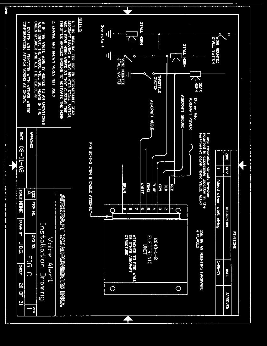
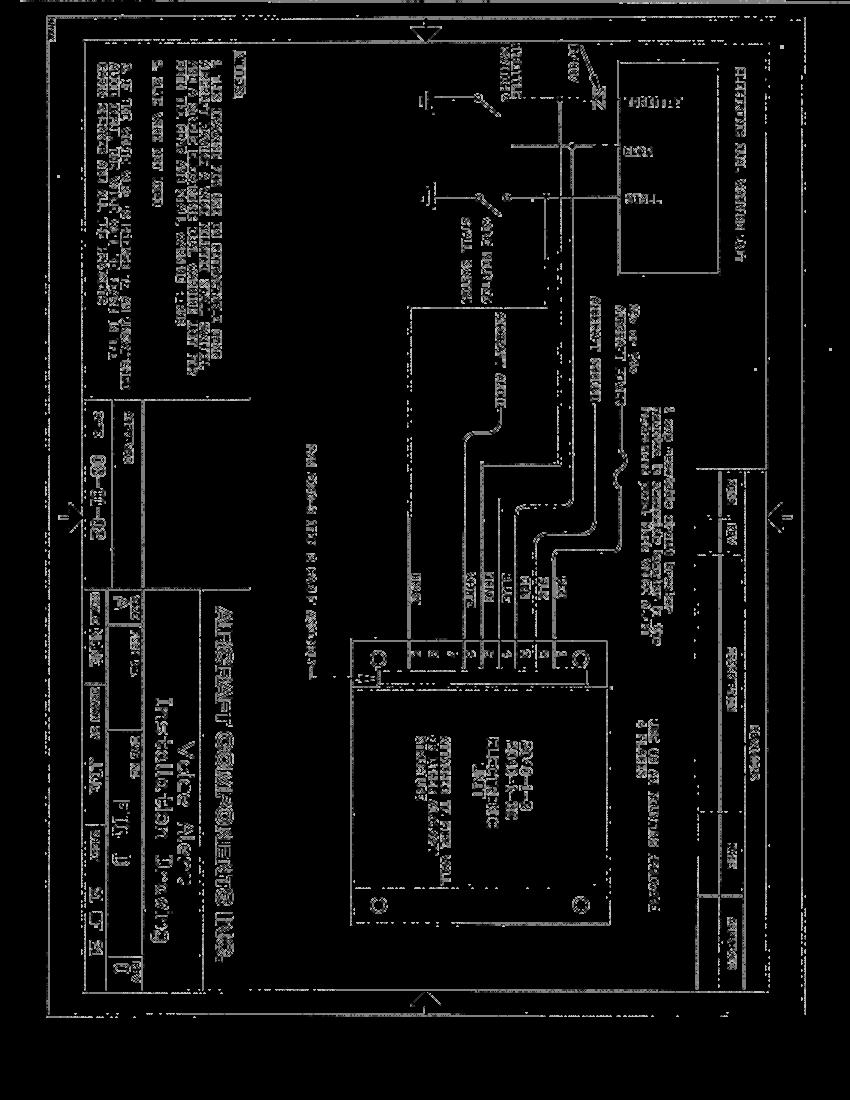
6 provided. Note: The circuit breaker must be the resetable type and must be mounted within the pilot s reach to allow turning the system off in flight if required. Normal current draw is 150 ma. b) Attach the BLACK wire to a good aircraft ground point using a ring connector provided. The ground wire should be bolted to the aircraft structure using a machine screw and nut. Refer to AC B, Section for details on grounding electronic equipment 3. Attach the WHITE wire to the aircraft audio system. The WHITE wire is a 600 ohm low level audio signal. This signal must be hooked to the aircraft audio system in such that it prevents the pilot from accidentally turning it off. If the aircraft has an audio panel with an un switched audio input, the white wire should be attached directly to this un switched input, so that the voice will be heard directly through the cabin speaker and headsets. If the aircraft does not have an un switched input, then the WHITE wire can be hooked directly into the pilots headset jack. 4. Locate the stall horn in the aircraft. Using a meter, measure the voltage on both sides of the stall horn when the horn is both sounding and silent. The voltage at one of the connections on the stall horn will change between aircraft voltage and ground as the horn activates. This is the point where the Voice Alert BLUE wire will connect. Connections can be made to the stall horn using a ring connector if the horn has terminals, or by soldering or splicing into the existing wiring harness. Refer toac B, Sections , , and for information on splicing and terminal installation. Refer to Installation Drawing FIG C. The actual aircraft stall system may be wired in either configuration, as shown on the drawing 5. Attach the GREEN wire to the gear horn connection that reads 0 volts when the horn is sounding, as defined above. Connections can be made to the gear horn using a ring connector, if the horn has terminals, or by soldering or splicing into the existing wiring harness. Refer to AC B, Sections , , and for information on splicing and terminal installation. 6. Cut the unused wires (ORANGE & BROWN) and secure against shorts. The unstripped cut ends can be doubled over and covered with a piece of the heat shrink tubing provided, and secured in the wire bundle. Attach the cable to the electronic box. This completes the installation. Proceed to Section IV for test of the system Section D. Installation in Retractable Gear Aircraft that use a single electronic dual warning unit for activating both the gear and stall warnings. The following section provides specific installation instructions for the retractable gear aircraft listed in the previous section that referenced Section III D. These aircraft use a single electronic dual warning unit for activating both the gear and stall warnings. Note: Before starting the installation, activate the stall warning horn and the gear warning horn and mentally note the level of the horn volume. This will allow a comparison of the horn volume after the installation to insure that it has not been effected by the installation. This installation requires a P/N Voice Alert Assembly. 1. Select a location to firmly mount the Electronic Module to the aircraft. It can be mounted to the firewall, side panel, or other secondary aircraft structure. Do not alter, modify or drill any aircraft structural members when making this installation. Page 10 of 21 Check to verify that the installation does not interfere with the aircraft controls or other installed equipment. Do not mount the electronic module within 6 inches of any high current drawing electronic equipment. Any additional wire required should be #22 gauge or larger, and must meet the wire type defined in AC B, Chapter 11, Section 7. Wiring should not be bundled with high current carrying conductors, coaxial antenna cables, or conductors carrying pulsed signals. Bundle and secure wiring. Refer to AC B, Sections through for additional information. Drill 4 mounting holes as shown on Fig 1. Mount the Electronic Module as shown on FIG 2, using the hardware provided. 2. Wire the system as shown on installation drawing FIG D, using the cable assembly provided. a)attach the RED wire to the 12v or 24v power buss through a 1 circuit breaker using a ring connector provided. Note: The circuit breaker must be the resetable type and within the pilots reach to allow turning the system off in flight if required. Normal current draw is 150 ma. b) Attach the BLACK wire to a good aircraft ground point using a ring connector provided. The ground wire should be bolted to the aircraft structure using a machine screw and nut. Refer to AC B, Section for details on grounding electronic equipment 3. Attach the WHITE wire to the aircraft audio system. The WHITE wire is a 600 ohm low level audio signal. This signal must be hooked to the aircraft audio system in a way, which prevents the pilot from accidentally turning it off. If the aircraft has an audio panel with an un switched audio input, the white wire should be attached directly to this un switched input so that the voice will be heard directly through the cabin speaker and headsets. If the aircraft does not have an un switched input, then the WHITE wire can be hooked directly into the pilot=s headset jack. 4. Locate the dual warning module in the aircraft, and attach the Voice Alert wires to the terminals on the dual warning unit as follows: a) Hook the BROWN wire to the terminal on the dual warning unit marked STALL SWITCH, as shown on the wiring schematic FIG D. 6/14
7 b) Hook the GREEN wire to the terminal on the dual warning unit marked GEAR, as shown on wiring schematic FIG D. c) Hook the ORANGE wire to the terminal on the dual warning unit marked THROTTLE SWITCH, as shown on wiring schematic FIG D. Connections can be made to the dual warning unit using a ring connector if the unit has terminals, or by soldering or splicing into the existing wiring harness. Refer to AC B, Sections , , and for information on splicing and terminal installation. 5. Cut the unused wire (BLUE) and secure against shorts. The unstripped cut ends can be doubled over and covered with a piece of the heat shrink tubing provided, and secured in the wire bundle. Attach the cable to the electronic box. This completes the installation. Proceed to section IV for test of the system. IV. System Test A. Ground Test This test is to be performed on the ground both with and without the engine running prior to flight: 1. Activate the aircraft existing stall and or gear warning horns. Note the volume level of the horn sound, and compare that sound level to the sound level experienced in the test of the system performed prior to the start of the installation. There must be no noticeable decrease in sound level. The headset volume can be adjusted by turning the volume adjust screw accessible on the electronic module. 2. With electrical power applied to the Voice Alert unit, individually turn on the various electrical devices in the aircraft. Use the table attached to this procedure as a guide for performing this test. The acceptance criteria given below must be met, as each electrical device is activated and then turned off. 3. Verify that the aircraft devices operate normally and are not affected by the Voice Alert. The acceptance criteria given below must be met. 4. Taxi the aircraft. The acceptance criteria given below must be met. B. Ground Test Acceptance Criteria The following criteria must be met for each part of the ground test. a) False triggering of the Voice Alert at any time constitutes failure of the test. b) If the Voice Alert, and/or the Stall or Gear Warning, activates when it should not, that constitutes failure of the test. c) If any electronic device in the aircraft does not operate correctly, turn off the Voice Alert and determine if it is the cause. If the Voice Alert effects the operation of any electronic device, that constitutes failure and must be corrected. d) There must be no noticeable decrease in the warning horn sound level after the system installation. C. Flight Test Procedure This test is to be performed with the aircraft in flight. Flight tests should be conducted at an altitude and in a flight area suitable for this activity. The acceptance criteria given below must be met during this test. 1. Perform a normal takeoff. 2. Fly the aircraft at different speeds from normal cruise speed to approach speed. The acceptance criteria given below must be met during this test. 3. Perform a stall. The Voice Alert must activate with the proper voice message whenever the aircraft stall warning sounds, and the voice must stop when the stall horn stops. The volume level must be adequate to hear and recognize the message above other sounds. Verify that the presence of a stall warning can be recognized along with simultaneous radio reception. Failure to fully meet this criteria constitutes failure of this test. (stalls should be performed at different power levels to insure the voice can be heard over the background sounds). 4. With the landing gear retracted, pull the throttle to idle. The Voice Alert must sound with the proper message at the time that the gear warning horn sounds, and it must stop when the gear horn stops. The volume level must be adequate to hear and recognize the message above other sounds. Verify that the voice message can be recognized along with simultaneous radio reception. Failure to fully meet this criteria constitutes failure of this test. 5. With the gear retracted and the throttle retarded, activate the gear warning horn and the voice message. Decrease the airspeed until the aircraft approaches a stall and the stall horn sounds. The voice message must instantly change to the stall warning message as the stall horn sounds. The voice message must change back to the gear warning message within 1 voice cycle after the stall warning stops, and the gear warning horn continues. Failure to fully meet this criteria constitutes failure of this test. 6. Individually turn on the various electrical devices in the aircraft. Use the attached table as a guide. As each device is activated, verify that its operation is not affected by the Voice Alert, and that the Voice Alert does not false trigger as the various electrical devices are turned on. 7/14
8 D. Flight Test Acceptance Criteria The following criteria must be met during the flight test. This is in addition to other criteria that may be defined in the individual test sections. a) False trigger of the Voice Alert at any time constitutes failure of this test. b) If the Voice Alert, and/or either the stall or gear warning, activates when it should not, that constitutes failure of the test. c) There must be no noticeable decrease in the stall or gear warning sound levels from that heard in the test performed prior to the start of the installation. V. Documentation 1. The installer is responsible for making log book entries, revised weight & balance, and other documentation as necessary. VI. Equipment The following is a listing of the parts and materials included with this kit. 1. (1) P/N or P/N Electronic Module 2. (1) P/N Cable Assembly 3. (4) Machine Screws, #8 X 32 X ½ RH P SS 4. (4) Hex Nuts, #8 X 32 self locking SS 5. (4) Flat Washers, #8 SS 6. (4) Insulated Ring Connectors, #8, wire 7. (20) Nylon Ty wraps 8. (1) Length 1/8 dia heat shrink 9. (1) Length 3/8 dia heat shrink 8/14

9 9/14

10 10/14
11 11/14
12 12/14
13 13/14

14 14/14
Remote Aural Warning System and Summing Amplifier Installation and Operation Manual
 9800 Martel Road Lenoir City, TN 37772 www.ps-engineering.com PRD60 Remote Aural Warning System and Summing Amplifier Installation and Operation Manual Document P/N 200-160-0200 Revision 3, Sept. 2012
ETSA380MF SHOWN WARNING. shall be used ONLY on approved vehicles. It is the sole responsibility of the user of these devices to ensure compliance.
 WARNING: Warning devices are strictly! WARNING Sirens produce loud sounds that may damage hearing: - Roll up windows. - Wear hearing protection. - Use only for emergency response. - Avoid exposure to siren
EW 40 Wireless Fan Control
 Installation & Operating Manual EW 40 Wireless Fan Control USA CAN Product Information... Chapters 1 + 2 Mechanical Installation... Chapter 3 Electrical Installation... Chapter 4 Start Up and Configuration...
A D U ANNUNCIATOR DIM / TEST UNIT INSTALLATION MANUAL DESCRIPTION AND THEORY OF OPERATION
 AVIONICS ENGINEERING SERVICES A D U ANNUNCIATOR DIM / TEST UNIT INSTALLATION MANUAL DESCRIPTION AND THEORY OF OPERATION Document No. 92-0003-06 REV C May 31, 2000 INSTALLATION MANUAL DESCRIPTION AND THEORY
Proper installation of this product requires the installer to have a good understanding of automotive electronics, systems and procedures.
 ENGINEERING COMPANY INC. 1 Winthrop Road Chester, Connecticut 0-0 Phone: (0) 2-0 Fax: (0) 2-07 Internet: www.whelen.com Sales e-mail: autosale@whelen.com Canadian Sales e-mail: autocan@whelen.com Customer
Automotive: Sirens/Switches
 ENGINEERING COMPANY INC. 51 Winthrop Road Chester, Connecticut 06412-064 Phone: (60) 526-9504 Fax: (60) 526-407 Internet: www.whelen.com Sales e-mail: autosale@whelen.com Canadian Sales e-mail: canadiansales@whelen.com
OWNERS MANUAL. CARBON MONOXIDE DETECTOR MODELS Panel Mount & Remote Detectors (R) Guardian Avionics 1951 E. AIRPORT DRIVE TUCSON, AZ.
 Guardian Avionics 1951 E. AIRPORT DRIVE TUCSON, AZ.") OWNERS MANUAL CARBON MONOXIDE DETECTOR MODELS Panel Mount & Remote Detectors (R) (353-101 and 353-201) 353 FAMILY MODEL OWNERS/INSTALLATION MANUAL Page 1 of 22 LOG OF REVISIONS REV NO. PAGE NO. DATE DESCRIPTION
OWNERS MANUAL CARBON MONOXIDE DETECTOR MODELS Panel Mount & Remote Detectors (R) (353-101 and 353-201) 353 FAMILY MODEL OWNERS/INSTALLATION MANUAL Page 1 of 22 LOG OF REVISIONS REV NO. PAGE NO. DATE DESCRIPTION
SERVICE BULLETIN REVISION
 Revision 1 REVISION TRANSMITTAL SHEET This sheet transmits Revision 1 to, which: A. Changes the test for the operation of the switch installation. B. Adds steps to drill a hole in the cabin entrance door
CO Guardian LLC Document No E. AIRPORT DRIVE Date: 08/25/10 OWNERS MANUAL
 OWNERS MANUAL PULSE OXIMETER AND CARBON MONOXIDE DETECTOR MODEL AERO-455 Rev. B 455 MODEL OWNERS/INSTALLATION MANUAL Page 1 of 21 LOG OF REVISIONS REV NO. PAGE NO. DATE DESCRIPTION APPROVED A 1 thru 20
WARNING AND TEST MASTER WARNING AND MASTER CAUTION SYSTEMS
 WARNING AND TEST MASTER WARNING AND MASTER CAUTION SYSTEMS The Warning and Caution systems are discussed here in conjunction with the Warning and Test Systems, primarily to cover the procedures for testing
THE COMMISIONER TM 200 WATT ELECTRONIC SIREN & PA SYSTEM Model 4200
 THE COMMISIONER TM 200 WATT ELECTRONIC SIREN & PA SYSTEM Model 4200 Your purchase of a Wolo electronic siren, THE COMMISIONER, is the perfect choice for reliable service. THE COMMISIONER is manufactured
Document No
 CO Guardian LLC 1951 E. Airport Dr. Tucson, AZ 85706 CARBON MONOXIDE DETECTOR MODEL 452 INSTALLATION AND OPERATIONAL MANUAL Document No. 01-2510-02 MODEL 452 INSTALLATION AND OPERATIONAL MANUAL Page 1
INSTRUCTIONS FOR CONTINUED AIRWORTHINESS
 1951 E. Airport Dr. Tucson, AZ 85706 INSTRUCTIONS FOR CONTINUED AIRWORTHINESS CARBON MONOXIDE DETECTOR MODEL 452 INSTALLATION FOR CESSNA MODEL 172 AIRCRAFT STC NO: ST9261LA-A RECORD OF REVISIONS No. Revision
Models , Equinox, and Sirens Clutch Replacement Service Manual
 Models 2001-130, Equinox, and 508-128 Sirens Clutch Replacement Service Manual 25500297 Rev. A0 1115 Printed in U.S.A. Copyright 2015 Federal Signal Corporation Contents Safety Messages... 3 General Description...
CO Guardian LLC Document: E. AIRPORT DRIVE Date: 11/15/05 OWNERS MANUAL
 OWNERS MANUAL CARBON MONOXIDE DETECTOR MODELS Panel mount and Remote Detectors (R) (353 and 353R) 353 FAMILY MODEL OWNERS/INSTALLATION MANUAL Page 1 of 22 LOG OF REVISIONS REV NO. PAGE NO. DATE DESCRIPTION
2012 AeroLEDs LLC Rev: IR Page 1
 Document 0000-0003 Installation Guide: AeroLEDs LLC Aerosun 967 East Park Center Boulevard P/N 01-2120 Suite # 381 LED Landing light with Boise, ID 83706-6700 built-in pulse recognition mode Phone: (208)
BB TM 508/509 ANTI TWO-BLOCK ALARM SYSTEM HYDRAULIC CRANE INSTALLATION. Greer Company Crane Systems. Greer Company
 BB TM 508/509 ANTI TWO-BLOCK ALARM SYSTEM HYDRAULIC CRANE INSTALLATION GREER COMPANY 1918 East Glenwood Place, Santa Ana, CA 92705 Tel: (714) 259-9702 FAX (714) 259-7626 BB TM 508/509 ANTI TWO-BLOCK ALARM
ANNUNCIATOR FIXED MODULE
 12 Clintonville Road Northford, CT 06472 Phone: 203-484-7161 Fax: 203-484-7118 THE ANNUNCIATOR FIXED MODULE Installation Manual for the AFM-16ATF and AFM-32AF Annunciator Modules Document # 15970 3/27/95
Interactive Technologies Inc North 2nd Street North St. Paul, MN Technical Manuals Online! -
 Security System Owner s Manual Interactive Technologies Inc. 2266 North 2nd Street North St. Paul, MN 55109 FCC Notices FCC Part 15 Information to the User Changes or modifications not expressly approved
CO Guardian LLC Document No E. AIRPORT DRIVE Date: TUCSON, AZ CO Guardian LLC 1951 E. Airport Dr.
 1951 E. AIRPORT DRIVE Date: 8-20-2004 CO Guardian LLC 1951 E. Airport Dr. Tucson, AZ 85706 OWNERS MANUAL CARBON MONOXIDE DETECTOR MODEL 452-201 REMOTE UNIT MODEL 452-201 OWNERS MANUAL Page 1 of 22 INTENTIONALLY
380 SERIES REMOTE SIREN ETSA380R
 ! WARNING Sirens produce loud sounds that may damage hearing: - Roll up windows. - Wear hearing protection. - Use only for emergency response. - Avoid exposure to siren sound outside of vehicle. Please
DWA2000. WAAS Annunciator. Installation and Operations Manual. Rev 1.1 December 2014
 DWA2000 WAAS Annunciator Installation and Operations Manual Rev 1.1 December 2014 Deklin Technologies Inc 413 Childe Harolds Lane Brentwood, TN 37027 Tel: (615) 819-0800 Fax: (615) 819-0801 www.deklintech.com
AIR-COOLED CONDENSING UNIT UNITS PRODUCED AFTER JANUARY, 1996 INDEX SCHEMATIC DIAGRAM FIG. NO.
 wiring diagrams AIR-COOLED CONDENSING UNIT 566D Sizes 120-240 Cancels: New WD 566D.120.1 11/15/96 UNITS PRODUCED AFTER JANUARY, 1996 INDEX UNIT 566D 120-240 ELECTRICAL CHARACTERISTICS (V-Ph-Hz) SCHEMATIC
M* #..--.!.++. <...<... D~ta.. ~ - - B.s.P.x. #...0. ~ E. List # FINAL SELECTOR TEST FRAME SD TESTS BATTERY CUTOFF PANEL OFFICES
 BELL SYSTEM PRACTICES Re!wtv to B. S. P. Coorccinator SECTION 25-259 -904PT Plant Series Issue A, January 963 This Practice Released on:.... Pacific Tel. M* #..--.!.++.
218 Trademark Dr Buda Texas STL Boss 200 Watt Siren Operation Manual and Instructions
 STL Boss 200 Watt Siren Operation Manual and Instructions Congratulations, you are the owner of a STL Boss 200 Watt Siren! Your siren is equipped with the latest technology and features at the best value
385 SERIES REMOTE HANDHELD SIREN ETSA385HR
 ! WARNING Sirens produce loud sounds that may damage hearing: - Roll up windows. - Wear hearing protection. - Use only for emergency response. - Avoid exposure to siren sound outside of vehicle. Please
2012 FALCON 2000LX SN 2000LX-247
 MACH 0.86 PASSENGERS 10 RANGE (NM) 4,000 AIRCRAFT LISTING DETAILS: Total Hours: 925 ENGINES: Pratt & Whitney PW308C Left Right Total Hours: 925 925 Engine Cycles: 341 341 APU: Honeywell GTCP36-150 Total
RELEASE DEVICE CONTROLS
 RELEASE DEVICE CONTROLS RELEASE DEVICE MODEL C+ INSTALLATION MANUAL UL LISTED CANADIAN LISTED CSFM: 7300-48:00 GENERAL DESCRIPTION: MADE IN THE U.S.A. S/N: The LM0-C+ Release Device/Control Panel is a
DWA2000. WAAS Annunciator. Installation and Operations Manual. Rev 1.0 August 2014
 DWA2000 WAAS Annunciator Installation and Operations Manual Rev 1.0 August 2014 Deklin Technologies Inc 413 Childe Harolds Lane Brentwood, TN 37027 Tel: (615) 819-0800 Fax: (615) 819-0801 www.deklintech.com
generic moving map with bezel removed Avidyne Entegra MFD for Piper or Cirrus aircraft Avidyne Entegra PFD for Piper or Cirrus aircraft
 AvSimMap_II.ac Avidyne map generic moving map AvSimMap_II_nobezel.ac Avidyne map generic moving map with bezel removed AvSimMFD_all.ac Avidyne MFD Avidyne Entegra MFD for Piper or Cirrus aircraft AvSimPFD_all.ac
Interrogator 200 Audio Verification Module (AVM)
") Interrogator 200 Audio Verification Module (AVM) Document Number: 466-1153 Rev. B July 1996 Audio Verification Module Use a maximum of 500 feet of cable for all speakers and microphones. For example, if
Interrogator 200 Audio Verification Module (AVM) Document Number: 466-1153 Rev. B July 1996 Audio Verification Module Use a maximum of 500 feet of cable for all speakers and microphones. For example, if
Victoreen Primalert 35 Area Radiation Monitor
 Victoreen 05-437 Primalert 35 Area Radiation Monitor Operators Manual March 2005 Manual No. 126011 Rev. 3 2003, 2005 Fluke Corporation, All rights reserved. Printed in U.S.A. All product names are trademarks
Owners Manual Operating Instructions Patent # 7,081,811
 A division of Radiotronics, Inc. Model HA-2510 Owners Manual Operating Instructions Patent # 7,081,811 1556 Cypress Dr Jupiter Fl 33469 Ph 561-746-0935 Fax 561-747-0845 Introduction The K9 Heat Alarm Pro
The TC-4F. Time Control Module C P/N 15972:C ECN For the Sensican 2000 Fire Alarm Control Panel
 12 Clintonville Road Northford, CT. 06472 (203) 484-7161 FAX:(203) 484-7118 The TC-4F Time Control Module For the Sensican 2000 Fire Alarm Control Panel Document # 15972 3/27/95 Revision C P/N 15972:C
WARNING AND TEST MASTER WARNING AND MASTER CAUTION SYSTEMS
 MODEL 680 WARNING AND TEST MASTER WARNING AND MASTER CAUTION SYSTEMS The Warning and Caution systems are discussed here in conjunction with the Warning and Test Systems, primarily to cover the procedures
Alert Service Bulletin
 2900 Selma Highway Montgomery, AL 36108 USA Tel: 334-386-5400 Fax: 334-386-5450 Alert Service Bulletin Combustion Heater P/N CD14048 or CD14048-1 Heater Pressure Decay Test Requirement 1. Planning Information
Sundance Spas SPA EQUIPMENT SYSTEM. Installation Instructions. P/N Rev. A
 Sundance Spas SPA EQUIPMENT SYSTEM Installation Instructions P/N 6530-456 Rev. A Contents Important Notices 1 Important Safety Instructions 2 Where to Place the Equipment System 3 Connecting Pipes Between
Kelly Aerospace Willoughby, OH NC , Rev. A FAA APPROVED AIRPLANE FLIGHT MANUAL SUPPLEMENT FOR LC40-550FG AIRFRAME DE-ICING SYSTEM
 Aircraft SN: Aircraft Registration Number: This supplement must be attached to the FAA approved flight manual when the Kelly Aerospace airframe de-icing system is installed in accordance with STC SA02660CH.
Street Thunder ST280 SIREN AMPLIFIER & LIGHT CONTROLLER INSTALLATION AND OPERATING INSTRUCTIONS
 Street Thunder ST280 SIREN AMPLIFIER & LIGHT CONTROLLER INSTALLATION AND OPERATING INSTRUCTIONS 1340 Russell Cave Road / P.O. Box 54308 Lexington, KY 40505 Tel: (800) 477-7766 Fax: (800) 944-2557 www.galls.com
TABLE OF CONTENTS GENERAL... 2 A. DEFINITIONS DIGITAL, ADDRESSABLE FIRE ALARM SYSTEM... 2
 Division 28 ELECTRONIC SAFETY AND SECURITY TABLE OF CONTENTS 28 0000 GENERAL... 2 A. DEFINITIONS...2 28 3111 DIGITAL, ADDRESSABLE FIRE ALARM SYSTEM... 2 A. DESIGN REQUIREMENTS...2 B. CONSTRUCTION REQUIREMENTS...2
Street Thunder ST240 SIREN AMPLIFIER INSTALLATION AND OPERATING INSTRUCTIONS
 Street Thunder ST240 SIREN AMPLIFIER INSTALLATION AND OPERATING INSTRUCTIONS 1340 Russell Cave Road / P.O. Box 54308 Lexington, KY 40505 Tel: (800) 477-7766 Fax: (800) 944-2557 Website: www.galls.com REV.
D169 2-Way Voice Verification Module. Installation and Operating Manual Radionics 34105B 3/97
 D169 2-Way Voice Verification Module Installation and Operating Manual Notice The material and instructions covered in this manual have been carefully checked for accuracy and are presumed to be reliable.
16 Zone Voice Evacuation VA & PA Sound System
 16 Zone Voice Evacuation VA & PA Sound System 4 Channel Main Amp VA-MP4120 PC Server & Software VA-2000ST T-565 Zone 1-4 One Channel Standby Amp VA-2000RM VA-2000MA T-565 Zone 5-8 LAN CAT5 Cable CAT5 Data
INSTALLATION, OPERATING, AND MAINTENANCE INSTRUCTIONS FOR Q-SIREN MODELS Q2B-012P, Q2B-012NN, AND Q-MT
 256A768K REV. K 506 Printed in U.S.A. INSTALLATION, OPERATING, AND MAINTENANCE INSTRUCTIONS FOR Q-SIREN MODELS Q2B-012P, Q2B-012NN, AND Q-MT SAFETY MESSAGE TO INSTALLERS The lives of people depend on your
MODEL ZAC ZONE ANNUNCIATOR/CONTROLLER DESIGNED FOR ZONE ANNUNCIATION AND MONITORING
 MODEL ZAC-32 32 ZONE ANNUNCIATOR/CONTROLLER DESIGNED FOR ZONE ANNUNCIATION AND MONITORING 32 HARD WIRED ZONES CAN BE NORMALLY-OPEN OR NORMALLY-CLOSED ZONE WIRING RUNS CAN BE AS FAR AS 10,000 FEET FROM
INSTALLATION MANUAL AND OPERATING INSTRUCTIONS
 INSTALLATION MANUAL AND OPERATING INSTRUCTIONS MD41-1200 SERIES TERRAIN AWARENESS ANNUNCIATION CONTROL UNIT for SANDEL ST3400 TAWS MD41-1248 28vdc Horizontal Mount MD41-1258 28vdc Vertical Mount (shown
USER MANUAL FOR OPERATING SYSTEM
 P2262 ALARM PANEL USER MANUAL FOR OPERATING SYSTEM 21765-07 September 1999 Associated Controls (Aust) PTY. LTD. 29 Smith Street, Hillsdale, NSW, 2036. PH (02) 9311 3255, FAX (02) 9311 3779 Page 1 of 177
WCAD-Series Vended Washers Troubleshooting And Fault Codes
 WCAD-Series Vended Washers Troubleshooting And Fault Codes Part # 8533-066-001 5/11 1 Common Troubleshooting Solutions Symptom Probable Cause Suggested Remedy 2 Machine does not start Machine will not
P.68 VARIANTS. SERVICE BULLETIN No. 195 Rev. 1 (Supersedes the previous issue dated 19 February 2014)
") vulcanair spa via g. pascoli, 7 80026 Casoria (Na) Italy Tel +39 081 5918111 Fax +39 081 5918172 info@vulcanair.com www.vulcanair.com P.68 VARIANTS Approved by the Vulcanair Design Organisation The technical
vulcanair spa via g. pascoli, 7 80026 Casoria (Na) Italy Tel +39 081 5918111 Fax +39 081 5918172 info@vulcanair.com www.vulcanair.com P.68 VARIANTS Approved by the Vulcanair Design Organisation The technical
Central Station SIA Protocal
 Sensor name or Type AC Power Failure AT AT AT AT AT AT AT AC Power Restored AR AR AR AR AR AR AR Alarm Cancel OC OC OC Police Alarm Cancelled PH BH PH PH Auto Force Arm CF CF CF CF CF Automatic Phone Test
OWNERS MANUAL OPERATION AND INSTALLATION PROCEDURE AND LIMITATIONS
 OWNERS MANUAL OPERATION AND INSTALLATION PROCEDURE AND LIMITATIONS CARBON MONOXIDE DETECTOR MODEL AERO 454-201 REMOTE UNIT Rev. D 454 MODEL OWNERS/INSTALLATION MANUAL Page 1 of 25 LOG OF REVISIONS REV
Axiom Technologies L.L.C Telephone: Pennbright Dr., Suite 220 Fax: XP7 USER S MANUAL
 L.L.C Telephone: 281 931 0907 255 Pennbright Dr., Suite 220 Fax: 281 931 6562 Houston, Texas 77090 www.axiomsafety.com XP7 USER S MANUAL COMPACT MULTI-CHANNEL ALARM & SHUTDOWN SYSTEM GENERAL The XP7 alarm
Safety Message to Installers of Federal Signal Siren Speakers
 Model RB-CRG11 Mounting Bracket Kit for the Rumbler Speaker in the 2011 and Newer Dodge Charger 2562629B REV. B 312 Safety Message to Installers of Federal Signal Siren Speakers People s lives depend on
Technical Manual. VFD / Cabinet Heater Upgrade 110 VAC Heater to 12 VDC Heater. Provided by: Chart Inc.
 Technical Manual VFD / Cabinet Heater Upgrade 110 VAC Heater to 12 VDC Heater Provided by: Chart Inc. 407 7th Street NW New Prague, MN 56071 USA (800) 400-4683 Part Number 20977233 Rev. A 2016 Chart Inc.
FAA APPROVED ROTORCRAFT FLIGHT MANUAL SUPPLEMENT FOR THE HONEYWELL MK XXII ENHANCED GROUND PROXIMITY WARNING SYSTEM (EGPWS) [Aircraft Type]
![FAA APPROVED ROTORCRAFT FLIGHT MANUAL SUPPLEMENT FOR THE HONEYWELL MK XXII ENHANCED GROUND PROXIMITY WARNING SYSTEM (EGPWS) [Aircraft Type]](/thumbs/95/125588824.jpg "FAA APPROVED ROTORCRAFT FLIGHT MANUAL SUPPLEMENT FOR THE HONEYWELL MK XXII ENHANCED GROUND PROXIMITY WARNING SYSTEM (EGPWS) [Aircraft Type]") FAA APPROVED ROTORCRAFT FLIGHT MANUAL SUPPLEMENT FOR THE HONEYWELL MK XXII ENHANCED GROUND PROXIMITY WARNING SYSTEM (EGPWS) [Aircraft Type] Serial No. This Supplement must be attached to the FAA Approved
FAA APPROVED ROTORCRAFT FLIGHT MANUAL SUPPLEMENT FOR THE HONEYWELL MK XXII ENHANCED GROUND PROXIMITY WARNING SYSTEM (EGPWS) [Aircraft Type] Serial No. This Supplement must be attached to the FAA Approved
GX-A604/GX-A602/GX-A3001
 GX-A604/GX-A602/GX-A3001 power amplifi er OWNER'S MANUAL INTRODUCTION THANK YOU for purchasing a JBL GX-series amplifier. So we can better serve you should you require warranty service, please retain your
EX-TECH SIGNALLING SAS SD100-1 WEATHERPROOF SOUNDER/HORN TECHNICAL MANUAL
 PRODUCT NAME: SD-100-1- WEATHER-PROOF SOUNDER/HORN DOC NO.: EX-TECH SIGNALLING SAS-12-SD100-1-TM REV03 WEATHERPROOF SOUNDER/HORN IP66 SD-100 SERIES EX-TECH SIGNALLING SAS SD100-1 WEATHERPROOF SOUNDER/HORN
ACSS Repair and Overhaul Capabilities List FA2100 Cockpit Voice Recorder L-3 Aviation Recorders
 Table 1. L3ZR029X and EASA145.5441 Capability ACSS Repair and Overhaul Capabilities List Base Part 2100-1025-12 FA2100 Cockpit Voice Recorder L-3 Aviation Recorders 2100-2043-12 FA2100 Flight Data Recorder
INSTRUCTION MANUAL (ATEX/IECEx/SIL2) BExBG05D-SIL Flameproof Xenon SIL 2 Beacons For use in Flammable Gas and Dust Atmospheres
 BExBG05D-SIL Flameproof Xenon SIL 2 Beacons For use in Flammable Gas and Dust Atmospheres") INSTRUCTION MANUAL (ATEX/IECEx/SIL2) BExBG05D-SIL Flameproof Xenon SIL 2 Beacons For use in Flammable Gas and Dust Atmospheres 1) Introduction The BExBG05D-SIL is a flameproof beacon which is certified
INSTRUCTION MANUAL (ATEX/IECEx/SIL2) BExBG05D-SIL Flameproof Xenon SIL 2 Beacons For use in Flammable Gas and Dust Atmospheres 1) Introduction The BExBG05D-SIL is a flameproof beacon which is certified
EXD-HP1/2 Stand-alone Superheat/Economizer Controller
 Technical Bulletin EXD-HP1/2 are stand-alone universal superheat and or economizer controllers for heat pumps, heating units, air conditioning and precision cooling such as telecom and shelter applications.
FAA APPROVED AIRPLANE FLIGHT MANUAL SUPPLEMENT
 SUPPLEMENTAL TYPE CERTIFICATE NUMBER SA11103SC INSTALLATION OF SAFETY SYSTEMS FOR BEECHCRAFT B200GT AND B200CGT AIRPLANES IN THE KING AIR 250 CONFIGURATION (PRO LINE 21 AND PRO LINE FUSION AVIONICS) FAA
Informer-IP Desk Mount
 Informer-IP Desk Mount Model I-IP-IO Two-Way IP-enabled Intercom and Alarm Initiation Point Key Fob is optional. (Version 3.2.0.1 and later) Description, Specifications, and Installation Manual 255378
INSTALLATION MANUAL AND OPERATING INSTRUCTIONS
 INSTALLATION MANUAL AND OPERATING INSTRUCTIONS MD41-1000 SERIES TERRAIN AWARENESS ANNUNCIATION CONTROL UNIT MD41-1028 28vdc Horizontal Mount MD41-1038 28vdc Vertical Mount (shown on page 12) MD41-1028(5V)
INSTALLATION MANUAL AND OPERATING INSTRUCTIONS MD SERIES TERRAIN AWARENESS ANNUNCIATION CONTROL UNIT FOR GARMIN TAWS SYSTEMS
 INSTALLATION MANUAL AND OPERATING INSTRUCTIONS MD41-1000 SERIES TERRAIN AWARENESS ANNUNCIATION CONTROL UNIT FOR GARMIN TAWS SYSTEMS MD41-1028 28vdc Horizontal Mount MD41-1038 28vdc Vertical Mount (shown
Services withdrawal: Declaration of plan to discontinue lease, rental, and maintenance services for selected machines
 IBM Canada Ltd. Withdrawal Announcement A15-0488, dated July 14, 2015 Services withdrawal: Declaration of plan to discontinue lease, rental, and maintenance services for selected machines Table of contents
400 SERIES REMOTE SIREN WITH REMOTE ROTARY CONTROL PANEL ETSA481RSR - 100W ETSA482RSR - 200W
 400 SERIES REMOTE SIREN WITH REMOTE ROTARY CONTROL PANEL ETSA481RSR - 100W ETSA482RSR - 200W Introduction The ETSA48(X)RSR is a remote mounted all in one siren and light controller. It comes in 2 styles
Chromalox. Installation, Operation. Screw Plug Heating Solution Control Panel Assembly for Screw Plug Heaters RENEWAL PARTS IDENTIFICATION
 Chromalox Installation, Operation and RENEWAL PARTS IDENTIFICATION DIVISION SALES REFERENCE DATE 4 (Supersedes PG422-) DECEMBER, 2000 SECTION RAD PE440 6-058074-002 Screw Plug Heating Solution Control
Yale Real Living Touchscreen Deadbolt Installation and Programming Instructions
 Yale Real Living Touchscreen Deadbolt Installation and Programming Instructions x3 #8-32 x 5/16" Machine screws x4 #7 wood & #8-32 machine x 20mm Combination screws x2 M6x47mm Long through bolt 1 Preparing
Owner s Manual For Model Aero-553 (Rev. A.)
") 1951 E. AIRPORT DRIVE Date: 11-16-10 Owner s Manual For Model Aero-553 (Rev. A.) Document: 553-553 MODEL OWNERS/INSTALLATION MANUAL Page 1 of 30 1951 E. AIRPORT DRIVE Date: 11-16-10 INTENIONALLY LEFT BLANK
1951 E. AIRPORT DRIVE Date: 11-16-10 Owner s Manual For Model Aero-553 (Rev. A.) Document: 553-553 MODEL OWNERS/INSTALLATION MANUAL Page 1 of 30 1951 E. AIRPORT DRIVE Date: 11-16-10 INTENIONALLY LEFT BLANK
Voice Dialer Temperature & Power Loss Monitor VD-5100-TM / VD-5101-TM
 Innovative Technologies n Custom Electronic Design & Manufacturing General Description The VD-5100-TM (Fahrenheit) and VD-5101-TM (Celsius) Voice Dialer monitors temperature and power status. Upon an alarm
 www.severntrentservices.com CAPITAL CONTROLS Series 70CV3000 Chloromatic TM Intelligent Gas Flow Control Valve The Series 70CV3000 Chloromatic TM Intelligent Gas Flow Control Valve is designed to control
CARSON MANUFACTURING CO., INC NORTH RURAL STREET INDIANAPOLIS, IN (888) TECHNICAL BULLETIN OFF/ON PA VOL
 TECHNICAL BULLETIN OFF/ON PA VOL") Carson MANUFACTURING COMPANY, INC. CARSON MANUFACTURING CO., INC. 5451 NORTH RURAL STREET INDIANAPOLIS, IN 46220 (888) 577 6877 www.carsonsirens.com TECHNICAL BULLETIN OFF/ON RADIO HRN/TT SIREN PA VOL
Carson MANUFACTURING COMPANY, INC. CARSON MANUFACTURING CO., INC. 5451 NORTH RURAL STREET INDIANAPOLIS, IN 46220 (888) 577 6877 www.carsonsirens.com TECHNICAL BULLETIN OFF/ON RADIO HRN/TT SIREN PA VOL
Installation Instructions. Fire Command Center/Fire Alarm Annunciators D1256/D1257
 Instructions Fire Command Center/Fire Alarm Annunciators D1256/D1257 74-06925-000-H Page 2 2004 Bosch Security Systems Contents 1.0 Introduction...5 1.1 Before You Begin...5 1.2 Type Styles Used Here...5
Yale Real Living Assure Lock Push Button Deadbolt Installation and Programming Instructions (YRD216)
") Yale Real Living Assure Lock Push Button Deadbolt Installation and Programming Instructions (YRD216) Optional Network Module x3 #8-32 x 5/16" Machine screws x4 #7 wood & #8-32 machine x 20mm Combination
Yale Real Living Assure Lock Push Button Deadbolt Installation and Programming Instructions (YRD216) Optional Network Module x3 #8-32 x 5/16" Machine screws x4 #7 wood & #8-32 machine x 20mm Combination
Addendum for STI-6406 with Dual Access Control
 Addendum for STI-6406 with Dual Access Control Description: This system contains a STI-6400 with a DPDT key switch to be mounted on one side of a door or wall; and a similar looking housing, also with
218 Trademark Dr Buda Texas STL Apex 150 Watt Siren Operation Manual and Instructions
 STL Apex 150 Watt Siren Operation Manual and Instructions Congratulations, you are the owner of a STL Apex 150 Watt Siren! Your siren is equipped with the latest technology and features at the best value
Equipment Alert. P-Trap Must Be Installed to Exhaust or Warranty will be Voided. Refer to this Manual for installation Instructions
 Dry Assembled Elbows MUST Glue when Installed Exhaust Connection P-Trap Must Be Installed to Exhaust or Warranty will be Voided AA2360 Refer to this Manual for installation Instructions 2011 Midmark Corp.
Supervised Security System Owner's Guide
 Owner's Guide PSC06 READ THIS FIRST This equipment generates and uses radio frequency energy, and if not installed and used properly, that is, in strict accordance with the manufacturers instructions,
Model 17A00 Expansion Enclosure
 HOME AUTOMATION, INC. Model 17A00 Expansion Enclosure Installation Manual Document Number 17I00-1 Rev A March, 2002 Home Automation, Inc. Model 17A00 Expansion Enclosure Installation Manual Document Number
REFERENCE ONLY FAA APPROVED AIRPLANE FLIGHT MANUAL SUPPLEMENT
 SUPPLEMENTAL TYPE CERTIFICATE NUMBER SA11103SC INSTALLATION OF SAFETY SYSTEMS FOR BEECHCRAFT B200GT AND B200CGT AIRPLANES IN THE KING AIR 250 CONFIGURATION (PRO LINE 21 AND PRO LINE FUSION AVIONICS) FAA
INSTALLATION INSTRUCTIONS AND OWNER S MANUAL
 INSTALLATION INSTRUCTIONS AND OWNER S MANUAL ELECTRIC INSTANTANEOUS WATER HEATERS WITH PhD 208 and 480 VAC three phase 32 144 kw 600 VAC three phase 130 / 150 kw BEFORE ATTEMPTING ANY INSTALLATION OR SERVICE
Installation Instructions for W2H Series Signals
 Installation Instructions for W2H Series Signals IF1513 A Description and Operation DIMENSIONS W2H A 8 7/8" (225 mm) B 8 1/4" (210 mm) C 13" (330 mm) Figure 1. Speaker/Amplifier Dimensions The W2H signaling
WCVD-Series OPL Washers Troubleshooting And Fault Codes. Starting serial number ****** (09/13)
") WCVD-Series OPL Washers Troubleshooting And Fault Codes Starting serial number ****** 8533-074-001 (09/13) Common Troubleshooting Solutions Symptom Probable Cause Suggested Remedy Machine does not start
WCVD-Series OPL Washers Troubleshooting And Fault Codes Starting serial number ****** 8533-074-001 (09/13) Common Troubleshooting Solutions Symptom Probable Cause Suggested Remedy Machine does not start
AVPTC Multi-Position, Internal Txv
 Multi-Position, Internal Txv Variable-Speed ECM Based Comfortnet Compatible Air Handler 1½ to 5 Tons Contents Air Handler Nomenclature... Heater Kit Nomenclature......3 Dimensions...4 Airflow Data...5
AVPTC. Multi-Position, Variable-Speed ECM Based Air Handler with Internal TXV ComfortNet Compatible 1½ to 5 Tons. Contents.
 Multi-Position, Variable-Speed ECM Based Air Handler with Internal TXV ComfortNet Compatible 1½ to 5 Tons Contents Air Handler Nomenclature... Heater Kit Nomenclature... Product Specifications... 3 Dimensions...
INSTALLATION AND INSTRUCTION MANUAL
 INSTALLATION AND INSTRUCTION MANUAL SS650-013 013 SIREN LCS652-013 SIREN and Light Controller PLITSTR247 REV. F 12/9/13 NOTICE Due to continuous product improvements, we must reserve the right to change
INSTALLATION MANUAL AND OPERATING INSTRUCTIONS
 INSTALLATION MANUAL AND OPERATING INSTRUCTIONS MD41-( ) Series GPS Annunciation Unit For Garmin GNS and GTN Systems MD41-1484W 14VDC Horizontal Mount MD41-1488W 28VDC Horizontal Mount MD41-1494W 14VDC
DYGIZONE GJD910 Lighting Controller & Enunciator
 DYGIZONE GJD910 Lighting Controller & Enunciator MASTER WIRING IDENTIFICATION Power up to the DygiZone and you will see: All the LED s (red,yellow,green and blue buttons) will flash All the LCD icons will
PRICE $4.00 MODEL PA4000 ELECTRONIC SIREN INSTALLATION, OPERATION, AND SERVICE INSTRUCTIONS
 PRICE $4.00 MODEL PA4000 ELECTRONIC SIREN INSTALLATION, OPERATION, AND SERVICE INSTRUCTIONS LIMITED WARRANTY The Signal Division, Federal Signal Corporation (Federal), warrants each new product to be free
Emergency Procedures Training
 Emergency Procedures Training Agenda (classroom) Aeroplane fire in the air and on the ground Hijacking, bomb threat and other security procedures Passenger on board medical emergency Agenda (Aircraft)
Global Water Instrumentation, Inc.
 Instrumentation, Inc. 11390 Amalgam Way Gold River, CA 95670 T: 800-876-1172 Int l: (916) 638-3429, F: (916) 638-3270 High Water Alarm WA400-DC WA400-AC WA400-BU WA400-FS WA400-AL 10/23/06 P/N: 01-527
INSTALLATION MANUAL AND OPERATING INSTRUCTIONS
 INSTALLATION MANUAL AND OPERATING INSTRUCTIONS MD41-( ) Series GPS Annunciation Unit For Garmin GNS 430/530 VHF Communication and Navigation Management System MD41-1484 14VDC Horizontal Mount MD41-1488
Table of Contents. Part I SAFETY MESSAGE TO INSTALLERS OF EMERGENCY WARNING EQUIPMENT 2 Part II Vehicle Operation 4. Part III Safety Messages 13
 Manual I SS2000 TouchScreen Installation Guide Table of Contents Foreword 0 Part I SAFETY MESSAGE TO INSTALLERS OF EMERGENCY WARNING EQUIPMENT 2 Part II Vehicle Operation 4 1 Installing the... SS2000 TouchScreen
CIRRUS AIRPLANE MAINTENANCE MANUAL
 INDICATING/RECORDING SYSTEMS 1. DESCRIPTION This section describes the Indicating/Recording Systems which consists of an Annunciator Panel and related sensors and switches. A. Annunciator Panel - Serials
Model PA300 Series ELECTRONIC SIREN MODELS , , ,
 Price $4.00 Model PA300 Series ELECTRONIC SIREN MODELS 690000, 690001, 690002, 690004 INSTALLATION AND OPERATING INSTRUCTIONS LIMITED WARRANTY The Signal Division, Federal Signal Corporation (Federal),
1126 Series Ceiling Mount PIR Motion Detector
 Installation Sheet 1126 Series Ceiling Mount PIR Motion Detector Description The 1126 Series PIR (Passive Infrared) Motion Detectors are a compact wireless PIR. The 1126 Series offer 360, Wide Angle, or
Page 1 of 18. Part# /5/2013
 Part# 1002655-06 8/5/2013 This manual contains important information concerning the installation and operation of the gun washers listed above. Read manual thoroughly and keep for future reference INSTRUCTIONS
SANTA ROSA FIRE DEPARTMENT FIRE PREVENTION BUREAU PLAN REVIEW CHECKLIST FIRE ALARM SYSTEM INSTALLATION
 July 1, 2010 SANTA ROSA FIRE DEPARTMENT FIRE PREVENTION BUREAU PLAN REVIEW CHECKLIST FIRE ALARM SYSTEM INSTALLATION Address: Permit #: Inspector: Date: Status: Inspector: Date: Status: A-Approved; AC-Approved
FlashGuard 3000B Dual Lighting System Troubleshooting Guide
 FlashGuard 3000B Dual Lighting System Troubleshooting Guide Table of Contents Section Flashhead (Strobe) Troubleshooting Flowchart 1 Multiple Strobe Troubleshooting Flowchart 2 Sidelight Troubleshooting
Unity DAU Voice Alarm System
 Unity DAU Voice Alarm System User Manual & Log Book Site Name Address Contractor Commissioned Introduction Voice Alarm (VA) systems are the quickest way to evacuate the public & staff from a building.