Safety with werma -products
|
|
|
- Gabriel Barrett
- 6 years ago
- Views:
Transcription

1 Safety w i t h W E R M A -p r o d u c t s
2

3 Safe is safe For over 50 years WERMA has been manufacturing electrical signal devices at the highest level. Thanks to our superior quality standards, consistent innovation, continuous product development and excellent service, we have grown steadily over the last few years. As leaders in this field of technology, we owe it to our customers to continue to build on this success. We therefore invest 10 % of our expenditure in new developments. In this way, we can offer our customers innovative products which are at the leading edge of technological development in every detail. In accordance with this philosophy, we have made it our goal to improve the range of products designed for deployment in hazardous areas. It is here in particular, where danger is at its greatest, that responsibility of those warning of such dangers is at its greatest.
4 The explosion oxygen e.g. in the air INFLAMMABLE SUBSTANCE e.g. gas, vapour, dust IGNITION SOURCE e.g. hot surfaces, electrical arcs An explosion is an extremely rapid oxidation or decomposition reaction accompanied by a sudden rise in temperature and pressure. As a rule, in order for explosions to occur in atmospheric air, three elements need to be present in the right proportions: Inflammable substance Oxygen (air) Ignition source Inflammable substances Inflammable refers to the capacity of substances to react with oxygen releasing light and/or thermal energy. Flammability is a precondition for combustion and thus for an explosion. Inflammable gases A gas is a substance that exists in a gaseous state at a temperature of 20 C. Many inflammable gases, especially those employed for heating or in technical applications, are compounds containing carbon and/or hydrogen. In combination with (air) oxygen an explosive atmosphere can form. Inflammable liquids Liquid refers to substances existing in a fluid state. Dependent on the characteristics of the substance, liquids display different evaporation rates. Evaporation refers to the transition to the gaseous state, a process that occurs without the necessity of the liquid being brought to boiling point. This can occur, depending on the liquid, at relatively low temperatures. This means that a potentially explosive atmosphere can build at the surface of inflammable liquids at room temperature and below. Inflammable solids If inflammable solids occur in the form of dust, fibres or lint, these can react with the atmospheric oxygen resulting in an explosion. In addition to the chemical properties of the substance, the size of the solid particles, i.e. the increase in the total surface area the finer the particles, plays an important role. The required ignition energy is generally greater than in the case of gases and vapours. Examples of inflammable dust include wood dust, cereal dust, flour dust, inflammable plastic dust, sugar dust and inflammable metal dust.
5

6 Oxygen A potentially explosive atmosphere can only occur when the concentration of the inflammable substance in the air lies within a specific range. This explosive range is defined by the upper and lower explosive limits. If the concentration of inflammable substance is too low, no explosion will take place, i.e. the concentration is too lean. If the concentration is too high there is not sufficient oxygen for an explosion to occur, i.e. the mixture is too strong. EXPLOSIVE RANGE AND EXPLOSIVE LIMITS 100 Vol. % concentration of air 0 Vol. % mixture too lean no explosion explosive range mixture too strong no explosion lower explosive limit upper 0 Vol. % concentration of inflammable substance 100 Vol. %
7 Ignition sources The ignition source provides the explosive mixture with the energy required to ignite. In the following the relevant types of ignition sources encountered in practice are discussed in more detail: HOT SURFACES Hot surfaces can ignite an explosive atmosphere when their temperature reaches the ignition temperature of the explosive mixture. Hot surfaces are sometimes intended (e.g. heating), however they also occur as a result of faults (overheating of bearings and brakes, defective electronic components etc.). FLAMES AND HOT GASES Flames are one of the most effective ignition sources. During normal operation flames and hot gases occur within combustion engines and analysis equipment. However within hazardous areas flames must be avoided or at the least, securely enclosed. MECHANICALLY GENERATED SPARKS Sparks can be generated during grinding, cutting and beating processes, depending on the combination of materials. By selecting a suitable combination of materials the occurrence of mechanically generated sparks can be reduced, e.g. by avoiding the combination of light metal and steel. CHEMICAL REACTIONS As a result of exothermic chemical reactions substances can be heated and thus form ignition sources. A raised ambient temperature or a defective heat dissipation can accelerate this process. ELECTRIC SPARKS Electric sparks can be generated by the opening and closing of electric circuits, even at low voltages. These sparks must generally be considered ignition sources. DISCHARGE OF STATIC ELECTRICITY Due to charge separation, sparks can be generated by static electricity, without the necessity of an electric voltage source. This also needs to be taken into consideration with non-electrical devices and components. Charge separation occurs for example when devices are not earthed or when they are included in a potential equalization. Electrostatic discharges can occur when wearing synthetic textiles, rolling paper and plastic foil and during pneumatic conveyance procedures (e.g. the extraction of bulk material, filling a silo). HIGH ENERGY WAVES Wave energy entering explosive atmospheres is also principally to be considered as an ignition source. Ultrasound, electromagnetic radiation in the form of radio waves, IR radiation and visible light, as well as ionising radiation can, with sufficient intensity, ignite an explosive mixture. In practice, these dangers extend from mobile telephones, radio telephonic devices, barcode scanners and light barriers etc. ADIABATIC COMPRESSION Adiabatic compression refers to an increase in pressure without an accompanying exchange of heat with the environment. The energy required for the reduction in volume is transformed into heat. A practical application of adiabatic compression is the self ignition of a diesel engine. The explosive fuel-air mixture is compressed in a cylinder until it is heated beyond the ignition temperature and ignites.
8 Avoidance of explosions explosion protection Three types of explosion protection can be defined: EXPLOSION PROTECTION Primary explosion protection: Preventing explosive atmospheres Secondary explosion protection: Preventing ignition sources Tertiary explosion protection: Reducing the effects of an explosion PrIMARY EXPLOSION PROTECTION Tertiary explosion Primary explosion protection entails preventing the formation of an explosive atmosphere by, for example adequate ventilation. secondary explosion protection Secondary explosion protection measures come into effect when an explosive atmosphere still arises despite primary explosion protection: they entail the elimination of ignition source. protection methods These minimise the effects of an explosion by a pressure-resistant building construction or the controlled transference of the explosion pressure. Legal basis The member states of the European Community have set forth new EU directives in order to harmonise different European rulings. This means that national regulations come into line with the regulations within the European Community. The basis of this new legal system is the European Directive 94 / 9 / EG dated This directive defines the obligations of the manufacturer in the form of the demands made upon products manufactured encompassing electrical, and non-electrical devices as well as protection systems. This directive is also known as the ATEX Directive in reference to its original working title Atmosphère explosible. As it is anchored in Article 95 of the EU Agreement its usual title is ATEX 95. All new production devices used inareas with explosion hazard must conform to the ATEX directive as from All devices and machines installed before this date may still be used. The basic standards for the construction of electrical devices are set forth in the EU Standards of the European Norm Organisation. Manufacturers obligations Safety in areas with explosive hazard can only be guaranteed through close cooperation between all those involved. Cooperation between manufacturer, installer, operator, tester and the relevant controlling body is essential. The essential obligations for the manufacturer of explosion protected components are: The devices must be marked according to their field of use. The Conformity Assessment Procedure demands that all requirements for the awarding of the CE mark be fulfilled. Devices in category 1 and 2 are to be tested by a third party testing authority toensure that all regulations are observed. This is to be confirmed by the Type Examination Certificate. The manufacturer must prove that he has an appropriate quality management system.
9 Areas liable to explosion: Zone definitions Areas liable to explosion as defined by 2 of the ElexV are areas in which a dangerous explosive atmosphere could arise due to site and production-induced conditions. In order to judge the degree of protective measures required, the areas liable to explosion are classified by the operator into zones according to the probability of an explosive atmosphere arising. Definitions of the zones acc. to 2 Para 4 of ELEXV (96) AREAS LIABLE TO EXPLOSION CAUSED BY FLAMMABLE GASES Zone 0 Zone 1 Zone 2 Areas in which a dangerous explosive atmosphere consisting of a mixture of air and gas, vapours or mist is present continually, over a longer period or on a frequent basis. Areas in which a dangerous explosive atmosphere consisting of gases, vapours or mist is to be expected from time to time. AREAS LIABLE TO EXPLOSION CAUSED BY FLAMMABLE DUST Zone 20 Zone 21 Zone 22 Sectors in which a dangerous explosive atmosphere consisting of a mixture of dust and air exists and is present continually, over a longer period or on a frequent basis. Sectors in which a dangerous explosive atmosphere consisting of a mixture of dust and air is to be expected from time to time. Areas in which a dangerous explosive atmosphere consisting of gases, vapours or mist is not to be expected and where it does arise then in all probability only rarely and for a short period of time. Sectors in which a dangerous explosive atmosphere caused by clouds of dust is not to be expected and where it does actually arise then in all probability only rarely and for a short period of time. Devices groups and categories Electrical components for use in areas liable to explosion can be divided in two groups: Group I: Electrical components in pit gas endangered mining areas. Group II: Electrical components in other areas liable to explosion from gas or dust. The device groups are further divided up into device categories according to the Ex Zone: AREAS LIABLE TO EXPLOSION CAUSED BY FLAMMABLE DUST Group I Group II Category M Category 1 Category 2 Category 3 G D G D G D 1 2 (Gas) (Dust) (Gas) (Dust) (Gas) (Dust) Zone 0 Zone 20 Zone 1 Zone 21 Zone 2 Zone 22


10 Specific construction regulations for explosion protected components in gaseous or vaporous atmospheres Specific construction regulations prevent electrical components in an explosion-endangered gas or vapour area from becoming a source of ignition. The so-called protection types guarantee safety depending on the Ex zone even in the event of malfunction. The general requirements for electrical components in gas explosion endangered areas are defined in the IEC ,EN (formerly: EN ) Part 0: general requirements.
11 Protection types in gas or vapour areas FLAME-PROOF ENCLOSURES d IEC , EN (previously: EN 50018) Electrical apparatus for explosive gas atmospheres Part 1: Flameproof enclosures d If an explosion occurs inside a pressure resistant encapsulated housing it cannot break through into the surrounding atmosphere. INCREASED SAFETY e IEC , EN (previously: EN 50019) Electrical apparatus for explosive gas atmospheres Part 7: Increased safety e Sparks and high temperatures cannot arise due to increased safety measures. INTRINSIC SAFETY i IEC , EN Electrical apparatus for explosive gas atmospheres Part 11: Intrinsic safety i The electric current in the circuit is kept so low that fiery sparks, arcing or temperatures cannot occur. pressurized apparatus p IEC , EN (previously: EN 50016) Electrical apparatus for explosive gas atmospheres Part 2: Pressurized enclosures p The formation of a potentially explosive atmosphere inside housings is prevented by maintaining a positive internal pressure of inert gas in relation to the surrounding atmosphere. ENCAPSULATION m IEC , EN (previously: EN 50028) Electrical apparatus for explosive gas atmospheres Part 18: encapsulation m Components which could ignite an explosive atmosphere are encapsulated in a casting compound to prevent the ignition of the surrounding atmosphere. OIL IMMERSION o IEC , EN Electrical apparatus for explosive gas atmospheres Part 6: Oil-immersion o Powder Filling q IEC , EN Electrical apparatus for explosive gas atmospheres Part 5: Powder filling q Oil filling Powder filling Explosive Atmosphere Explosive Atmosphere Parts that could constitute an ignition source are completely surrounded by a protective liquid (e.g. oil), in order to prevent the ignition of an outer explosive atmosphere. Parts that could constitute an ignition source are securely arranged and completely surrounded by a filling material in order to prevent the ignition of an outer explosive atmosphere. PROTECTION TYPE n IEC , EN (previously: EN 50021) Electrical apparatus for explosive gas atmospheres Part 15: Construction, test and marking of type of protection n electrical apparatus n Special types of protection for applications in zone 2 and 22 include a description of the different protection principles. Dependent on the protection principle, the type of protection is supplemented with the addition of a letter.

12 Explosion groups for gases and vapours The inflammability and ignition penetration power of an explosive mix is a substance typical property. Explosive mixtures of air with inflammable gases or vapours are divided into explosion groups I and II. Explosion group I applies to pit gas and is only relevant in mining. In explosion group II the inflammability of the gases increases from IIA to IIB and IIC. These define different criteria e.g with protection type d-pressure-resistant encapsulation (EN ) the requisite slit types and dimensions, or, as in protection type i-intrinsic safety (EN 50020), the maximum permissible electricity and current ratings. No further sub-division of explosion group II is made for other protection types. EXPLOSION GROUP INFLAMMABLE SUBSTANCE INFLAMMABILITY I Methane A Aceton, Petrol, Methanol, Propane, Toluene relatively low II B Ethylene C Hydrogen, Acetylene high
13 Temperature classification of gases and vapours The ignition temperature of explosive gaseous and vaporous atmospheres is influenced by several different factors. These include size, type and consistence of the heated surface. The IEC contains a Method of determining ignition temperature with which it is possible to calculate the lowest practically possible temperature with relative accuracy. Gases and vapours are classified here in in temperature classes. Explosion-protected components are laid out in their surface temperature so that ignition cannot occur on the surface. IGNITION TEMPERATURES AND TEMPERATURE CLASSES OF EXPLOSION-ENDANGERED GAS AND VAPOUR ATMOSPHERES Temperature classes Ignition temperature of the explosion-liable gas / vapour atmosphere Permissible surface temperature of the component T1 450 C 450 C T C 300 C T C 200 C T C 135 C T C 100 C T C 85 C The explosion group and the temperature class define which gas and vapour atmospheres the explosion protected equipment may be deployed in. The following table indicates the temperature class and explosion group for a series of inflammable gases and vapours: EXPLOSION GROUP AND TEMPERATURE CLASSIFICATION OF GASES AND VAPOURS Temperature Classification T1 T2 T3 T4 T5 T6 Explosion Group I Methane IIA Ammonia Methane Ethane Propane Ethyl alcohol Cyclohexane n-butane n-hexane Petrol Diesel IIB Town gas Ethylene Hydrosulfide Ethylene glykol Acetaldehyd Ethyl aether IIC Hydrogen Acetylene Coal disulfide

14 Special construction requirements for explosion protected equipment in dust atmospheres The construction requirements set down in the standards EN and IEC are designed to prevent electrical equipment in an explosive dust atmosphere from acting as an ignition source. The general requirements for electrical equipment in dust explosion hazardous areas are set down in the norms IEC * and EN * (draft). * Electrical equipment for use in areas with inflammable dust Part 0: General Requirements.
15 Protection types in dust areas CENELEC (European Committee for Electrotechnical Standardisation) has established the norms EN and EN These norms are also reproduced as a German set of standards. At present the IEC, within the framework of the unification of the dust and gas norms, is working to align the numbering of the dust Ex norms to the system employed in the IEC standards. This will result in a gas and dust explosion protection equivalent for the set of standards. The norms for the dust explosion protection can be found in the standards IEC 61241, EN (draft) and EN Protection by enclosure td IEC , EN , EN Electrical apparatus for use in the presence of combustible dust Part 1: Protection by enclosures td Pressurization pd IEC , EN (draft) Electrical apparatus for use in the presence of combustible dust Part 4: Type of protection pd The housing is dustproof. The Ex atmosphere is kept away from the ignition source, the surface temperature of the housing is restricted. The formation of an explosive atmosphere inside housings is prevented by a protective gas that maintains an overpressure relative to the surrounding atmosphere. Intrinsic Safety id IEC , EN (draft) Electrical apparatus for use in the presence of combustible dust Part 11: Protection by intrinsic safety id Encapsulation md IEC , EN Electrical apparatus for use in the presence of combustible dust - Part 18: Protection by encapsulation md The energy in the electric circuit is kept so low that sparks, electric arcs and high temperatures that could serve as ignition sources cannot occur. Parts that could ignite an explosive atmosphere as a result of sparks are embedded in a potting compound so that the explosive atmosphere cannot be ignited.
16 Per missible surface temperature of electrical components in dust atmospheres IEC , EN Electrical apparatus for use in the presence of combustible dust Part 2: Test methods Section I: Methods for determining the minimum ignition temperature of dust. Different values are to be expected depending on whether the dust is in the form of a gathered layer (Value A) or as an active cloud (ValueB). The permissible surface temperature for component parts exposed to dust is calculated as such: 75K is deducted from value A and 2/3 of value B calculated. The smaller of the two values is the highest permissible surface temperature. Aclassification in explosion groups and temperature classes cannot be defined: these must always be evaluated specifically for the type of dust present. EXAMPLES OF IGNITION TEMPERATURES FOR SOME DIFFERENT DUST TYPES Solid matter Value A Ignition temp. according to EN layer ( C) Value B Ignition temp. according to EN cloud ( C) Permissable surface temperature ( C) Smallest value of calculation (A-75K) and 2/3*B >300 >280 >260 >230 >215 >200 >180 >165 >160 >135 Examples of natural products Cotton Lignite Grain Milk powder Examples of chemical-technical products Soot Polyvinylchloride Sulphur Examples of metal dust Iron Magnesium
17
18


19 Guaranteeing your satisfaction Extreme care must be taken when manufacturing Ex products. Such a rigorous approach begins at WERMA long before the first production step. Our employees are specially trained in all issues relating to Ex products in instruction courses and production workshops. The complete production area has been set up in accordance with the regulations applying to this sensitive field of production and extended with WERMA s own developments. When it comes to selecting our materials we do not make any compromises. Only material of the highest quality is used, ensuring that our products function failure-free, even under the toughest of conditions. No Ex product enters serial production without being inspected and approved by an independent external test centre and subjected to extensive functional tests and quality controls in our own quality assurance department. Over the last years our customers have been highly satisfied with us - we aim to ensure that this continues in the future.
 155 mm x 425 mm Housing Aluminium, glass Connection Screwable connection max. 2.5 mm 2 Contact protection according to VDE incl.")

20 740 Ex Signal Tower Zone 1 and 2, Zone 21 and 22 Signal tower KombiSIGN in flame-proof enclosure Available with up to 3 light elements Also available as LED version TECHNICAL SPECIFICATIONS Dimensions (Diameter x Height) 155 mm x 425 mm Housing Aluminium, glass Connection Screwable connection max. 2.5 mm 2 Contact protection according to VDE incl. approved pressure resistant cable gland NPT 3/4 Explosion protection II 2G EEx d II C T6 II 2D Ex II IP66 85 C Approval L.C.I.E. 97 ATEX 6012 ORDER SPECIFICATIONS Voltage V Bulb 24 V LED Current consumption 45 ma per tier Starting current < 0.5 A red / green red / yellow / green Life duration up to100,000 hrs ACCESSORIES Bulb BA 15d, 5 W, 24 V Bulb BA 15d, 5 W, 230 V TECHNICAL DIAGRAMS +40 C 6.3 kg IP66-20 C

: 75 mm x 77 mm x 228 mm 3 tier (L x B x H): 75 mm x 77 mm x")


21 741 Ex Signal Tower Zone 1 and 2 Competitively priced Ex LED Signal Tower No additional zener barrier required Combination of encapsulation m and intrinsic safety ib with connection area e TECHNICAL SPECIFICATIONS Dimensions of the Zener Barrier (L x B x H) 75 mm x 77 mm x 110 mm Dimensions total 2 tier (L x B x H): 75 mm x 77 mm x 228 mm 3 tier (L x B x H): 75 mm x 77 mm x 262 mm Housing Polyester Connection Screwable connection max. 2.5 mm 2 incl. approved cable gland e Explosion protection II 2G EEx me [ib] IIC T6 Approval PTB 06 ATEX 2005 ORDER SPECIFICATIONS Voltage 24 V = Current consumption < 90 ma red / green red / yellow red / yellow / green Life duration up to100,000 hrs TECHNICAL DIAGRAMS 2 tier 3 tier +50 C 690 g 710 g IP65-20 C

 II 3D IP65 (fulfills T 75 C, when")
22 770 Ex LED Installation Beacon Ex LED Permanent Beacon with M 20 thread Suitable for use in gas and dust explosion endangered areas (Zone 2 and 22) Extremely high light intensity Modern Chip-On-Board technology Ideal for installation in limited space due to short thread TECHNICAL SPECIFICATIONS Housing PC, black Dome PC, transparent Connection 2 wires, c. 115 mm long Fixing Installation mounting for Ø 20.5 mm (M 20 x 1.5 mm) Dimensions (Diameter x Height) 28.7 mm x 38.5 mm Operating voltage 24 V = Starting current < 0.5 A at 24 V Current consumption < 45 ma at 24 V Explosion protection II 3G Ex na II (fulfills T4, when temperature at place of operation lies between -20 and +50 C) II 3D IP65 (fulfills T 75 C, when temperature at place of operation lies between -20 and +50 C) Approval BVS 05 E 041 U Seal included in assembly. ORDER SPECIFICATIONS Voltage 24 V = red green yellow clear TECHNICAL DIAGRAMS Mainly sidewards illumination +40 C 12 g IP65-20 C
 Modern Chip-On-Board technology TECHNICAL SPECIFICATIONS Housing PC, black Dome PC, transparent Connection 2 wires, c. 115 mm long Fixing Installation mounting for Ø 22.5 mm (M 22 x 1.")
 II 3D IP65 (fulfills T 75 C, when")
23 771 Ex LED Installation Beacon Ex LED Permanent Beacon with M 22 thread for the control panelprogramme Extremely high light intensity Suitable for use in gas and dust explosion endangered areas (Zone 2 and 22) Modern Chip-On-Board technology TECHNICAL SPECIFICATIONS Housing PC, black Dome PC, transparent Connection 2 wires, c. 115 mm long Fixing Installation mounting for Ø 22.5 mm (M 22 x 1.5 mm) Dimensions (Diameter x Height) 28.7 mm x 38.5 mm Operating voltage 24 V = Starting current < 0.5 A at 24 V Current consumption < 45 ma at 24 V Explosion protection II 3G Ex na II (fulfills T4, when temperature at place of operation lies between -20 and +50 C) II 3D IP65 (fulfills T 75 C, when temperature at place of operation lies between -20 and +50 C) Approval BVS 05 E 041 U Seal included in assembly. ORDER SPECIFICATIONS Voltage 24 V = red green yellow clear TECHNICAL DIAGRAMS Mainly sidewards illumination +40 C 16 g IP65-20 C
 195 mm x 305 mm Housing Aluminium Dome Reinforced borosilicate glass Mounting Plate VA")
24 783 Ex Rotating Mirror Beacon Suitable for use in gas and dust explosion endangered areas (Zone 1 and 2, Zone 21 and 22) Flame-proof enclosure d with e connection area High life duration thanks tolow wear wheel and disc drive Can be mounted as required TECHNICAL SPECIFICATIONS Dimensions (Diameter x Height) 195 mm x 305 mm Housing Aluminium Dome Reinforced borosilicate glass Mounting Plate VA stainless steel Connection Screwable connection max. 2.5 mm 2 Cable gland Cable gland M 20 x 1.5 mm Cable diameter 5 13 mm Connection area Increased Safety e Drive Wheel and disc drive, motor in centre of gravity Installation position as required Mirror rotation rate 180 r.p.m. Service life of drive > 5,000 hrs Duty cycle 100% Fixing Base mounting, Bracket mounting, Tube mounting Explosion protection II 2G Ex de IIC T3 T4 (depending on version) II2D Ex td A21 IP 66 T 105 C T 150 C (depending on version) Approval PTB 06 ATEX 1039 Halogen bulb included in assembly. ORDER SPECIFICATIONS Voltage 24 V 24 V 115 V 230 V ~ 230 V ~ Halogen bulb 20 W 35 W 35 W 20 W 35 W Current consumption 900 ma 1.6 A 350 ma 110 ma 170 ma Temp. Class (gas) T4 T3 T3 T4 T3 Surface Temp. (dust) 105 C 150 C 150 C 105 C 150 C red yellow ACCESSORIES Wire guard (Accessory) Wire guard Mounting plate Clamp for tube mounting 1 1/ Clamp for tube mounting 1 1/ Clamp for tube mounting Bracket SPARE PARTS Clamp for tube mounting (Accessory) Halogen bulb 20 W for 24 V Halogen bulb 20 W for 230 V ~ Halogen bulb 35 W for 24 V Halogen bulb 35 W for 115 V ~, 230 V ~ TECHNICAL DIAGRAMS Mounting plate (Accessory) see next page +40 C Bracket (Accessory) 4.6 kg IP66-20 C
")

25 784 Ex Revolving Signal Beacon Suitable for use in gas and dustexplosion endangered areas (Zone 1 and 2, Zone 21 and 22) 3 Fresnel lenses effect light convergence and optimise visibility Flame-proof enclosure d with e connection area Low rotation rate and high life duration thanks to low wear wheel and disc drive Can be mounted as required TECHNICAL SPECIFICATIONS: Dimensions (Diameter x Height) 195 mm x 305 mm Housing Aluminium Dome Reinforced borosilicate glass Mounting Plate VA stainless steel Connection Screwable connection max. 2.5 mm 2 Cable gland Cable gland M 20 x 1.5 mm Cable diameter 5 13 mm Connection area Increased Safety e Drive Wheel and disc drive, motor in centre of gravity Installation position as required Halogen bulb G W 12 V / 24 V Lens rotation rate 60 r.p.m. Service life of drive > 5,000 hrs Duty cycle 100 % Fixing Base mounting, Bracket mounting, Tube mounting Explosion protection II 2G Ex de IIC T4 II 2D Ex td A21 IP 66 T 105 C Approval PTB 06 ATEX 1039 Halogen bulb included in assembly. ORDER SPECIFICATIONS Voltage 24 V 115 V 230 V ~ Current consumption 1.6 A 350 ma 170 ma red yellow ACCESSORIES Wire guard (Accessory) Wire guard Mounting plate Clamp for tube mounting 1 1/ Clamp for tube mounting 1 1/ Clamp for tube mounting Bracket SPARE PARTS Clamp for tube mounting (Accessory) Halogen bulb 35 W for 115 V ~, 230 V ~ Halogen bulb 35 W for TECHNICAL DIAGRAMS see next page Mounting plate (Accessory) +40 C Bracket (Accessory) 4.6 kg IP66-20 C
 195 mm x 305 mm Housing Aluminium Dome Reinforced borosilicate glass Mounting Plate VA stainless")
26 738 Ex Double Flash Beacon Suitable for use in gas and dust explosion endangered areas (Zone 1 and 2, Zone 21 and 22) Flame-proof enclosure d with e connection area High flash power from two consecutive flashes Can be mounted as required TECHNICAL SPECIFICATIONS Dimensions (Diameter x Height) 195 mm x 305 mm Housing Aluminium Dome Reinforced borosilicate glass Mounting Plate VA stainless steel Connection Screwable connection max. 2.5 mm 2 Cable gland Cable gland M 20 x 1.5 mm Cable diameter 5 13 mm Connection area Increased Safety e Installation position as required Flash energy 15 Ws Flash frequency 1 Hz Life duration 4 x 10 6 flashes Fixing Base mounting, Bracket mounting, Tube mounting Explosion protection II 2G Ex de IIC T5 II2D Ex td A21 IP 66 T 85 C T 90 C (depending on the voltage) Approval PTB 06 ATEX 1039 ORDER SPECIFICATIONS Voltage 24 V = 115 V ~ 230 V ~ Current consumption 700 ma 300 ma 200 ma Surface Temperature (dust) 85 C 90 C 85 C red yellow ACCESSORIES Wire guard (Accessory) Wire guard Mounting plate Clamp for tube mounting 1 1/ Clamp for tube mounting 1 1/ Clamp for tube mounting Bracket TECHNICAL DIAGRAMS see next page Clamp for tube mounting (Accessory) Mounting plate (Accessory) Bracket (Accessory) 4.4 kg IP C -20 C 15 Ws


27 Technical Diagrams 738, 783, 784 and Accessories 738 / 783 / 784 Ex-leuchten Clamp for tube mounting 1 1/ Clamp for tube mounting 1 1/ Wire guard Clamp for tube mounting Mounting plate Bracket


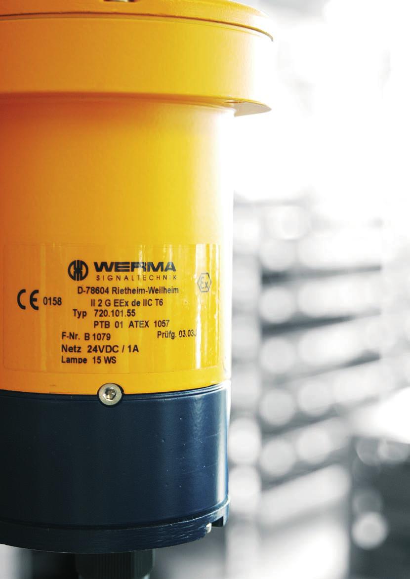
28 720 Ex Flashing Beacon Zone 1 and 2 Compact flashing beacon Versatile use TECHNICAL SPECIFICATIONS Dimensions (Diameter x Height) 110 mm x 243 mm Housing Aluminium Dome Reinforced borosilicate glass Wire guard Rust-proof steel, powder-coated Connection Screwable 1.5 mm 2 fine-strand, 2.5 mm 2 single-wire Cable entry Cable gland M 20 x 1.5 mm Cable diameter 6 9 mm Current consumption at 24 V: 1 A at 230 V: 200 ma Life duration 5 x 10 6 flashes Explosion protection II 2G EEx de IIC T6 Approval PTB 01 ATEX 1057 Fixing Bracket mounting, installation mounting Flash frequency 1 Hz ORDER SPECIFICATIONS Voltage 24 V = 230 V ~ red yellow TECHNICAL DIAGRAMS +40 C 15 2 kg IP67-20 C Ws

, UV-resistant, black Stainless steel V4A (ASTM316), rust-free Cable gland M 20 x 1.5 mm Cable diameter 6 13 mm up to 2.")
29 710 Ex Loudspeaker Zone 1 and 2 Sound output up to 119 db (A) Connection area e UV-resistant Protected against corrosion TECHNICAL SPECIFICATIONS Dimensions (Depth x Width) Housing Fixing bow, lid screw Cable entry Connection Connection area Input-output Connection voltage Max. Power 70 Hz Hz Power levels via code terminals SPL 25 W / 1m SPL 1 W / 1 m Transmission range Transmission range according to IEC Distortion factor 1 W / 1 khz 4 % Distortion factor 10 W / 1 khz 5 % Opening angle 1 khz 6 db mm x 219 mm Plastic (anti-static), UV-resistant, black Stainless steel V4A (ASTM316), rust-free Cable gland M 20 x 1.5 mm Cable diameter 6 13 mm up to 2.5 mm 2 (AWG14) solid up to 4 mm 2 stranded Increased safety e max. 500 W, parallel connection of up to 20 loudspeakers 100 V 25 W 25 W; 12,5 W; 8 W; 4 W; 2 W; 1 W c. 119 db (A) c. 107 db (A) 280 max. 10,000 Hz 330 6,000 Hz Opening angle 4 khz 6 db 40 Fixing Wall mounting Explosion protection II 2 G EEx dem IIC T5 Approval PTB 04 ATEX 1110 ORDER SPECIFICATIONS Spannung 100 V ~ TECHNICAL DIAGRAMS 3.5 kg IP C -20 C max. 119 db
 93 mm x 103 mm Housing ABS Connection Screwable connection max. 2.5 mm 2 Cable entry Kabeldurchmesser max.")

30 714 Ex Multi-Tone Sounder Zone 0, 1 and 2 26 tones for a diverse range of applications For use with a Zener Barrier Adjustable sound output to 103 db High protection rating IP 65 Direct external setting of two tones possible TECHNICAL SPECIFICATIONS Dimensions (Diameter x Depth) 93 mm x 103 mm Housing ABS Connection Screwable connection max. 2.5 mm 2 Cable entry Kabeldurchmesser max. 12 mm Duty cycle 100 % Operating voltage 24 V DC Current consumption 14 ma Tone types and frequencies adjustable via DIP switch, see table on right-hand page Fixing Wall mounting, base mounting Installation position Sound outlet must not face upwards Explosion protection II 1G EEx ia IIC T4 Approval Baseefa 06 ATEX 0161 ORDER SPECIFICATIONS: Voltage 24 V = ACCESSORIES Zener Barrier TECHNICAL DIAGRAMS 300 g IP C -20 C 103 db

31 714 Ex Multi-Tone Sounder The 714 Ex Multi-Tone Sounder offers a large choice of international signal tones for the widest spectrum of applications. TONE TYPES AND FREQUENCIES adjustable via DIP switch Tone A Tone type No. 1 Alternating 800 / 970 Hz in 2 Hz stroke 2 Rising 800 / 970 Hz in 7 Hz stroke 3 Rising 800 / 970 Hz in 1 Hz stroke 4 Continuous 2,850 Hz 5 Rising 2,400 2,850 Hz in 7 Hz stroke 6 Rising 2,400 2,850 Hz in 1 Hz stroke ,200 Hz rising in 3 sec., 0.5 sec OFF 8 Falling 1, Hz in 1 Hz stroke 9 Alternating 2,400 / 2,850 Hz in 2 Hz stroke 10 Pulse 970 Hz in 0.5 Hz stroke 11 Alternating 800 / 970 Hz in 1 Hz stroke 12 Pulse 2,850 Hz in 0.5 Hz stroke Hz pulse: 0.25 sec. ON / 1 sec. OFF 14 Continuous 970 Hz Hz / 100 ms alternating 440 Hz / 400 ms Hz pulse: 150 ms ON, 150 ms OFF Hz pulse: 1.8 sec. ON, 1.8 sec OFF Hz pulse: 6.5 sec. ON, 13 sec OFF 19 Continuous 660 Hz 20 Alternating 554 / 440 Hz in 0.5 Hz stroke 21 Pulse 660 Hz in 1Hz stroke 22 2,850 Hz pulse: 150 ms ON / 100 ms OFF 23 Rising 800 / 970 Hz in 50 Hz stroke 24 Rising 2,400 2,850 Hz in 50 Hz stroke Hz pulse: 3 x 500 ms ON, 500 ms OFF, 1.5 sec. pause 26 2,850 Hz pulse: 3 x 500 ms ON, 500 ms OFF, 1.5 sec. pause


32 750 Ex Signal Horn Zone 1 and 2 Signal horn for Ex protected areas Fully encapsulated Silicone free TECHNICAL SPECIFICATIONS Dimensions (D x W x H) 152 mm x 148 mm x 356 mm Housing PC / ABS-Blend Connection Cable 3 m, 2 x 0.75 mm 2 Fixing Bracket mounting, sound outlet facing downwards Explosion protection II 2G EEx m II T5 Approval BVS 03 ATEX E 118X ORDER SPECIFICATIONS Voltage 24 V = 24 V ~ 48 V ~ 115 V ~ 230 V ~ Voltage 21.6 V V V V V V... range 26.4 V 26.4 V 52.8 V V 131 V 250 V (50 Hz) (60 Hz) Current 350 ma 450 ma 220 ma 205 ma 70 ma consumpt TECHNICAL DIAGRAMS 1.3 kg IP C -40 C 105 db
 207 mm x")

33 761 Ex Signal Horn Zone 1 and 2, Zone 21 and 22 Loud horn with continuous tone Modern design Cable gland Connection area e Concealed fixing screws IP 65 for indoor and outdoor applications Flexible mounting possibilities Suitable for use in areas liable to explosion caused by both gas or dust without the need for additional accessories TECHNICAL SPECIFICATIONS Dimensions (D x W x H) 207 mm x 178 mm x 104 mm Fixing dimensions (D x W) 160 mm x 130 mm Housing PC Connection CAGE CLAMP max. 2.5 mm 2 Cable entry Cable gland M 16 x 1.5 mm, Cable diameter 5 9 mm Fixing Wall mounting, Surface mounting Explosion protection II 2G EEx me II T5, II 2D IP65 70 ORDER SPECIFICATIONS Voltage 24 V = 24 V ~ 48 V ~ 115 V ~ 230 V ~ Voltage 21.6 V V V V V V... range 26.4 V 26.4 V 52.8 V V 131 V 250 V (50 Hz) (60 Hz) Current 350 ma 450 ma 220 ma 205 ma 70 ma consumpt TECHNICAL DIAGRAMS 1.3 kg IP C -40 C max. 105 db
 43 mm x 48 mm Housing ABS Connection Spades 6.3 x 0.8 mm Audio frequency c.")

 975 118 00 Zener Barrier 975 714 01")
34 718 Ex Electronic Installation Buzzer Zone 1 and 2 Intrinsically safe Ex installation buzzer For use with a Zener Barrier IP 43 with cap Low current consumption Continuous tone TECHNICAL SPECIFICATIONS Dimensions (Diameter x Depth) 43 mm x 48 mm Housing ABS Connection Spades 6.3 x 0.8 mm Audio frequency c. 2,400 Hz Duty cycle 100 % Explosion protection II 2G EEx ib IIC T4 / T5 / T6 Approval DMT 98 ATEX E 005 X Maximum values of the Zener barrier Ui: 40 V =, li: 660 ma Minimum values for 24 V = of the Zener barrier 15 V = / 20 ma Maximum Input Power Pi Temp.- Max. surrounding temperature Class + 40 C + 50 C + 60 C T4 Pi = 1.3 W Pi = 1.2 W Pi = 1.0 W T5 Pi = 0.82 W Pi = 0.66 W Pi = 0.52 W T6 Pi= 0.6 W Pi = 0.45 W Pi = 0.3 W Cap ORDER SPECIFICATIONS Voltage 24 V = Current consumption 20 ma ACCESSORIES PC / ABS-Blend Cap (IP 43) Zener Barrier TECHNICAL DIAGRAMS with cap 50 g IP30 IP C -20 C 90 db


35 Make no compromises When it comes to the safety of your employees and equipment you should make no compromises. Those working in especially hazardous areas need to know that no expense has been spared in ensuring their safety. In the petrochemical and chemical industry these risks are readily apparent, however even in a joiner s workshop highly explosive mixtures can occur, placing special demands on the warning and signalling equipment. WERMA guarantees you the highest quality for maximum safety. Your job is dangerous enough as it is!
36

 4 Device group, e.g. II 5 Device category, e.g. 2G or 2D 6 Symbols to show that one or more norms from norm series EN 60079 (formerly EN 50014ff.")
37 Minimum product mar king of explosion-protected components The Directive 94 / 9 / EG (ATEX 95) section II defines an unequivocal marking for components in explosion-protected areas. This must include the following points: Name and address of the manufacturer Series number where applicable Description of series and type Details referring to the explosion protection type (examples): Gas 0102 II 2 G EEx me II T5 dust 0102 II 2 D IP C CE conformity marking 2 The number of the named authority monitoring production 3 Ex-Hexagon taken from the old regulations for explosive atmospheres (76 / 117 / EWG, 82 / 130 / EWG) 4 Device group, e.g. II 5 Device category, e.g. 2G or 2D 6 Symbols to show that one or more norms from norm series EN (formerly EN 50014ff.) or IEC / EN 61241) have been used. E = built acc. to European norm EX = Explosion protected component 7 Abbreviation of the protection type. All these used in the component must be named after the main ignition protection type, in the case of dust (protection through housing) additionally the IP rating. e.g. me : Main ignition protection type m, secondary type e. 8 Explosion group, eg II 9 Temperature class eg T5. In the case of dust (electrical apparatus protected by enclosures) the maximum surface temperature must be given. Components for Zones 2 and 22 may not bear the ATEX mark in their device classification or display the number of a monitoring authority. The details of the authority responsible for the testing of the component for the relevant norms must also be stated: BVS 03 ATEX E 118 X 3RD PARTY TESTING AUTHORITY YEAR OF TESTING ACC. TO DIRECTIVE 94/4/EG CONSECUTIVE NO. OF CERTIFICATE SPECIAL CONDITIONS An example of product marking on an explosion-protected electrical component: Zone I: Only to be wiped with a damp cloth. The minimal marking is augmented by recommendations vital for safe use. The certificate of conformity is to be provided with every device as well as the compulsory marking. The manufacturer hereby confirms conformity with the relevant norms and clearly states upon which EU standards the CE mark is based. An instruction and mounting leaflet is to be provided with every device. These documents should be filed safely by the user for future reference.

38 Ever ything you need to know at a glance

39 This page contained a poster with the most important international Ex markings. A replacement poster can now be ordered under: or Tel +49 (0)
 74 24 95 57-0 Fax +49 (0) 74 24 95")
40 WERMA Signaltechnik GmbH + Co. KG D Rietheim-Weilheim Fon +49 (0) Fax +49 (0) info@werma.com 11/ E
The R. STAHL Technology Group Worldwide Success with Competence and Customer Support
 The R. STAHL Technology Group Worldwide Success with Competence and Customer Support The entrepreneurial basis of the R. STAHL Technology Group follows a long tradition. The product range is aimed at specialised
Explosion-protected actuator Page 259 of 292
 Explosion-protected actuator Page 259 of 292 9.5 Explosion-protected actuator 9.5.1. What is an explosion? A flammable substance and oxygen, in a certain mixture, must be available to set off an explosion.
Hazardous Areas - EXPLOSIONPROOF SOLENOIDS
 Hazardous Areas - EXPLOSIONPROOF SOLENOIDS SOME HISTORY The classification of hazardous areas into zones established the level of protection required for electrical equipment installed in explosive gas
A GUIDE TO EUROPEAN (EEC) CERTIFICATION FOR ELECTRICAL EQUIPMENT IN HAZARDOUS AREAS
 CERTIFICATION FOR ELECTRICAL EQUIPMENT IN HAZARDOUS AREAS") A GUIDE TO EUROPEAN (EEC) CERTIFICATION FOR ELECTRICAL EQUIPMENT IN HAZARDOUS AREAS For a print friendly page click here INTRODUCTION Hazardous areas are those in which there exists a risk of explosion
A GUIDE TO EUROPEAN (EEC) CERTIFICATION FOR ELECTRICAL EQUIPMENT IN HAZARDOUS AREAS For a print friendly page click here INTRODUCTION Hazardous areas are those in which there exists a risk of explosion
REGULATIONS EUROPEAN ATEX DIRECTIVE. INTERNATIONAL SCHEME: IECEx AREAS CLASSIFICATION DEFINED BY DIRECTIVE 1999/92/EC
 EUROPEAN ATEX DIRECTIVE > European Directive 2014/34/EU ATEX Directive 2014/34/EU is a "new approach" directive that applies to protective systems against explosions as well as all equipment used in or
Weighing Solutions for Hazardous Areas FULL COMPLIANCE WITH ATEX DIRECTIVE
 Weighing Solutions for Hazardous Areas FULL COMPLIANCE WITH ATEX DIRECTIVE PUE HX5.EX explosion-proof hazardous area indicator ATEX APPROVAL PUE HX5.EX is a cutting-edge weighing indicator, designed to
Guide for hazardous areas
 Guide for hazardous areas 1 Hazardous areas definitions 2 Gas and dust s 3 Temperature classifications 4 Common flammable gases, vapours and dust types 5 Protection concepts ATEX and IECEx 6 Protection
ATEX Safety Switches. More than safety.
 ATEX Safety Switches More than safety. AUDIN - 8, avenue de la malle - 5370 Saint Brice Courcelles Tel : 03.6.0.0. - Fax : 03.6.0.8.0 - Web : http: www.audin.fr - Email : info@audin.fr ATEX products from
ATEX, NOMENCLATURE AND CODING
 Technical Notes ATEX, NOMENCLATURE AND CODING The intent of this technical note is approach to the user to the ATEX normative. For this we will begin defining, what is an explosive atmosphere, what are
1. GENERAL TECHNICAL INFORMATION
 1. GENERAL TECHNICAL INFORMATION 1.1 EXPLOSIVE ATMOSPHERES: Every time that dangerous quantities and concentration of flammable gas, vapors mixture or dust clouds exists, risk of explosions may arise.
PYROS. Código: FT-PY01-I Revisión: TECHNICAL DATA. Polycarbonate tube of 4 mm. thickness LIGHT FITTING. Laquered steel painted white
 . TECHNICAL DATA LIGHT FITTING REFLECTOR Polycarbonate tube of 4 mm. thickness Laquered steel painted white END CAPS Aluminium 2030 (polyester paint RAL 7047) POWER SOURCE LAMP TYPE 220-240V, 50/60Hz T8
EUROPEAN DIRECTIVES Explosive atmospheres ATEX 2014/34/EU
 EUROPEAN DIRECTIVES Explosive atmospheres ATEX 2014/34/EU GENERAL The accidental ignition of an atmosphere containing a large quantity of gas, vapour, mists and/or dust may cause an explosion. Specific
Implementation of ATEX Guidelines
 Implementation of ATEX Guidelines Temperature and Climatic Test Chambers for Usage under Conditions Carrying a Risk of Fire and Explosion What are ATEX guidelines? Introduction Duties of the system user...
ATEX GUIDE. A short introduction to ATEX Terminology. Equipment for use in flammable atmospheres. Directive 94/9/EC
 Quick Introduction to TÛV Denmark TÜV Denmark - is a part of the TÜV NORD Group a global Organisation f Certification and Inspection of: Quality Management Systems, Products, Processes and Qualification
ATEX, NOMENCLATURE AND CODING
 ATEX, NOMENCLATURE AND CODING The intent of this technical note is approach to the user to the ATEX normative. For this we will begin defining, what is an explosive atmosphere, what are ATEX, as well as
Airo Wireless Intrinsically Safe White Paper. Written By: David Schmitt
 Airo Wireless Intrinsically Safe White Paper Written By: David Schmitt Intrinsically Safe Cell Phone/Smartphone/PDA Intrinsically Safe (IS) is a protection certification for safe operation with electronic
ATEX - GUIDE. A short introduction to ATEX Terminology. Equipment for use in flammable atmospheres
 Quick Introduction to: DANISH TECHNOLOGICAL INSTITUTE The Danish Technological Institute is a self-owned and not-fprofit institution. We develop, apply and disseminate research- and technologically-based
ATEX - GUIDE. A short introduction to ATEX Terminology. Equipment for use in flammable atmospheres C E R T I F I E D DANISH TECHNOLOGICAL INSTITUTE
 DANISH TECHNOLOGICAL INSTITUTE The Danish Technological Institute is a self-owned and not-f-profit institution. We develop, apply and disseminate research- and technologically-based knowledge f the Danish
Guidelines for Market Surveillance of Equipment for Explosive Environments (Hazardous Locations)
") Annex II Guidelines for Market Surveillance of Equipment for Explosive Environments (Hazardous Locations) 1. According to Recommendation L, market surveillance should be included as a flanking area of
Annex II Guidelines for Market Surveillance of Equipment for Explosive Environments (Hazardous Locations) 1. According to Recommendation L, market surveillance should be included as a flanking area of
HAZARDOUS AREA CLASSIFICATION AND SELECTION OF EQUIPMENT FOR SAFE USE THEREIN FROM AN ELECTRICAL VIEWPOINT
 HAZARDOUS AREA CLASSIFICATION AND SELECTION OF EQUIPMENT FOR SAFE USE THEREIN FROM AN ELECTRICAL VIEWPOINT Olof Bekker Pr. Eng. BSc. Eng. BML S.MSAIEE, M.NACE Engineering Manager, Electrical COMMITMENT
Seat Ventilation offers an extensive range of ATEX certified products and is undertaking great efforts to extend this range even further.
 ATEX SOLUTIONS In order to apply a single level for health and safety requirements and to overcome barriers of trade within Europe, national regulations for explosion prevention were harmonized in 1975
[ TECHNOLOGY ] and does this definition affect a burner.
![[ TECHNOLOGY ] and does this definition affect a burner.](/thumbs/72/67499288.jpg "[ TECHNOLOGY ] and does this definition affect a burner.") [ TECHNOLOGY ] JBD-11,500-G type burner for natural gas ATEX, EExd Zone 2. For combined cycle power plant in Riga Latvia. Aitor Fernández Project Engineer Automation Department Head afernandez@emcombustion.es
[ TECHNOLOGY ] JBD-11,500-G type burner for natural gas ATEX, EExd Zone 2. For combined cycle power plant in Riga Latvia. Aitor Fernández Project Engineer Automation Department Head afernandez@emcombustion.es
Selection of Explosion Protected Equipment for Hazardous Locations. Compiled by: Pieter Coetzee ZONE 2 ZONE 1 ZONE 0.
 Selection of Explosion Protected Equipment for Hazardous Locations Compiled by: Pieter Coetzee ZONE 2 ZONE 0 ZONE 1 Be safe be Ex Contents Introduction Occupational Health and Safety Act. (Act 85 of 1993)
INSTRUCTION MANUAL IS-mB1 Minialite Intrinsically Safe Round LED Beacon
 INSTRUCTION MANUAL Minialite Intrinsically Safe Round LED This instruction sheet describes installations which conform to EN60079:Part14:2008 Electrical Installation in Hazardous Areas. When designing
A guide to the use of electrical equipment in potentially explosive atmospheres To view this document in PDF format click here.
 A guide to the use of electrical equipment in potentially explosive atmospheres To view this document in PDF format click here Introduction Potentially Explosive Atmospheres exist where there is a risk
OPTIBAR DP 7060 Supplementary Instructions
 OPTIBAR DP 7060 Supplementary Instructions Differential pressure transmitter Category ATEX II 1/2G, 2G Ex db ia IIC T6...T1 Ga/Gb, Gb IECEx Ex db ia IIC T6...T1 Ga/Gb, Gb Housing Aluminium: Single chamber,
NATIONAL RULES FOR ELECTRICAL INSTALLATIONS IN POTENTIALLY EXPLOSIVE ATMOSPHERES. ET 105:2001 (Second Edition)
") NATIONAL RULES FOR ELECTRICAL INSTALLATIONS IN POTENTIALLY EXPLOSIVE ATMOSPHERES ET 105:2001 (Second Edition) Consolidated Amendments, Corrigenda and Errata 01/2010 Introduction When ET 105:2001 was originally
NATIONAL RULES FOR ELECTRICAL INSTALLATIONS IN POTENTIALLY EXPLOSIVE ATMOSPHERES ET 105:2001 (Second Edition) Consolidated Amendments, Corrigenda and Errata 01/2010 Introduction When ET 105:2001 was originally
VSD AND SS DRIVING ATEX MOTORS February 2014
 VSD AND SS DRIVING ATEX MOTORS February 2014 1 Introduction to ATEX 2 ATEX motor designation 3 VSD Sample Solutions 4 SS descriptions Introduction to ATEX EU territory define the use of electrical equipment
4) Intrinsic Safety Certification
 Intrinsic Safety Certification") INSTRUCTION MANUAL Minialert Intrinsically Safe Round Combined Unit Section Volume Control Tone Generator S2 S3 Tone Selection Switches Fig 1 Simplified block diagram The combined unit is CE marked for
INSTRUCTION MANUAL Minialert Intrinsically Safe Round Combined Unit Section Volume Control Tone Generator S2 S3 Tone Selection Switches Fig 1 Simplified block diagram The combined unit is CE marked for
RE: USE OF FIREPRO IN POTENTIALLY EXPLOSIVE ATMOSPHERES
 Limassol 20 th August, 2015 RE: USE OF FIREPRO IN POTENTIALLY EXPLOSIVE ATMOSPHERES This document is intended to provide clarification on the use of FirePro Condensed Aerosol Generators in Potential Explosive
DSF xx15.xx xhv Ex-Atex Ex-Atex Certified Two wire Hall Effect Speed Sensor
 DSF xx15.xx xhv Ex-Atex Product ID Type # Product # Drawing # DSF 1215.01 SHV Ex-atex (5m) 304Z-05197 113216 DSF 1415.01 AHV Ex-atex S148 304Z-05256 113351 DSF 1615.01 SHV Ex-atex (5m) 304Z-05196 113214
DSF xx10.xx xhv Ex-Atex Hall Effect Single Channel Speed Sensor
 Product ID Type # Product # Drawing # DSF 1210.00 SHV Ex-atex (2m) 374Z-05066 110428F1 DSF 1210.00 SHV Ex-atex (5m) 374Z-05176 110428F1 DSF 1210.00 SHV Ex-atex (10m) 374Z-05590 110428F1 DSF 1410.00 SHV
Overview of Hazardous Locations as They Relate to Solenoid Valves
 Overview of Hazardous Locations as They Relate to Solenoid Valves Defined: Hazardous Location - "where fire or explosion hazards may exist due to flammable gases or vapors, flammable liquids, combustible
Drive Technology \ Drive Automation \ System Integration \ Services * _0817* Inquiry Forms for Explosion-Proof Gearmotors
 Drive Technology \ Drive Automation \ System Integration \ Services *23511257_0817* Inquiry Forms for Explosion-Proof Gearmotors Edition 08/2017 23511257/EN SEW-EURODRIVE Driving the world Inquiry forms
WHAT WHITE PAPER IS POTENTIALLY EXPLOSIVE ATMOSPHERE CERTIFICATION AND WHY YOU. June 2010
 WHITE PAPER WHAT IS POTENTIALLY EXPLOSIVE ATMOSPHERE CERTIFICATION AND WHY YOU MAY NEED IT! June 2010 Copyright Extronics Ltd 2010 The information contained in this document is subject to change without
INSTRUCTION MANUAL (ATEX / IECEx)
") INSTRUCTION MANUAL (ATEX / IECEx) BExS110D and BExS110D-R Sounder For use in Flammable Gas and Dust Atmospheres BExS110D BExS110D-R 1) Warnings DO NOT OPEN WHEN AN EXPLOSIVE ATMOSPHERE IS PRESENT DO NOT
INSTRUCTION MANUAL (ATEX / IECEx) BExS110D and BExS110D-R Sounder For use in Flammable Gas and Dust Atmospheres BExS110D BExS110D-R 1) Warnings DO NOT OPEN WHEN AN EXPLOSIVE ATMOSPHERE IS PRESENT DO NOT
Technical Data. Dimensions
 0102 Model Number Features 8 mm non-flush Stainless steel housing Usable up to SIL2 acc. to IEC 61508 Technical Data specifications Switching element function NAMUR, NC Rated operating distance s n 8 mm
INTRODUCTION TO DUSTS AND THEIR EXPLOSIVE PROPERTIES
 INTRODUCTION TO DUSTS AND THEIR EXPLOSIVE PROPERTIES Olof Bekker Pr. Eng. BSc. Eng. BML S.MSAIEE, M.NACE Engineering Manager, Electrical and Facilities DUST EXPLOSION! 1 DEFINITION Dust consists of small
ATEX Vacuum Pumps in Accordance with the Directive 94/9/EG (ATEX 95) Technical Information
 Technical Information") ATEX Vacuum Pumps in Accordance with the Directive 94/9/EG (ATEX 95) Technical Information 100.90.02 ATEX Certified Vacuum Pumps Oerlikon Leybold Vacuum offers a selection of different types of vacuum
ATEX Vacuum Pumps in Accordance with the Directive 94/9/EG (ATEX 95) Technical Information 100.90.02 ATEX Certified Vacuum Pumps Oerlikon Leybold Vacuum offers a selection of different types of vacuum
ESSENTIAL EXPLOSION PROTECTION
 ESSENTIAL EXPLOSION PROTECTION 2 3 FOREWORD In many industries, gases, vapours, mist and dust develop and escape in the course of manufacturing, processing, transporting and storing combustible substances.
ATEX 137. What it means for motor users
 ATEX 137 What it means for motor users ATEX puts responsibility for explosion protection firmly in the lap of the end user, who is responsible for the safe operation of all the equipment on his site. ATEX
Hazardous Area Classification in Oil & Gas Industry. A Fire Prevention Tool
 Hazardous Area Classification in Oil & Gas Industry A Fire Prevention Tool SFPE ENGINEERING TECHNOLOGY CONFERENCE Oct 4, 2010 New Orleans, LA 1 Overview Oil and gas plants handle flammable materials 2
Official Journal of the European Union
 C 20/16 27.1.2009 Commission communication in the framework of the implementation of the Directive 94/9/EC of the European Parliament and the Council on the approximation of the laws of the Member States
Technical Data. General specifications Switching element function Rated operating distance s n 5 mm
 0102 Model Number Features 5 mm non-flush Usable up to SIL2 acc. to IEC 61508 Technical Data specifications Switching element function NAMUR, NC Rated operating distance s n 5 mm Installation non-flush
INSTRUCTION MANUAL (ATEX / IECEx)
") INSTRUCTION MANUAL (ATEX / IECEx) BExBG15E and BExBG10E Flameproof / Increased Safety Xenon Beacons For use in Flammable Gas and Dust Atmospheres 1) Introduction The BExBG15E and BExBG10E beacons are flameproof
INSTRUCTION MANUAL (ATEX / IECEx) BExBG15E and BExBG10E Flameproof / Increased Safety Xenon Beacons For use in Flammable Gas and Dust Atmospheres 1) Introduction The BExBG15E and BExBG10E beacons are flameproof
Intrinsically Safe Pressure Transmitters for installation in hazardous locations Models IS-20-S, IS-21-S, IS-20-F, IS-21-F WIKA Datasheet IS-20
 Electronic Pressure Measurement Intrinsically Safe Pressure Transmitters for installation in hazardous locations Models IS-20-S, IS-21-S, IS-20-F, IS-21-F WIKA Datasheet IS-20 Applications Chemical, Petrochemical
PEPPERL+FUCHS GmbH
 Comfort series 1.5 mm embeddable M8x1 4 25 16 13 LED Switching element function NAMUR NC Rated operating distance s n 1,5 mm Installation embeddable Assured operating distance s a 0... 1,215 mm Reduction
S T R I T T & P R I E B E I N C.
 Equipment Enclosure Comparisons Type of Enclosure European - Area of use Designation Standard IEC - Area of use Designation Standard USA - Area of use Designation Standard Flameproof Enclosure An enclosure
MICROpeL 75 Combustible Gas Sensor Part Number: PM
 MICROpeL 75 Combustible Gas Sensor Part Number: PM759-000 Key Features & Benefits: ATEX, UL and CSA Approvals Withstands EN/IEC 60079-0 impact test Enhanced H 2 S and silicone poison resistance Reduced
Technical Data. General specifications Switching element function Rated operating distance s n 8 mm
 0102 Model Number Features 8 mm non-flush Usable up to SIL 3 acc. to IEC 61508 Application Danger! In safety-related applications the sensor must be operated with a qualified fail safe interface from Pepperl+Fuchs,
Intrinsic Safety. Intrinsically Safe Solutions. Accurate Weighing in Hazardous Areas
 Intrinsic Safety Intrinsically Safe Solutions Accurate Weighing in Hazardous Areas Accidents in hazardous areas can have dramatic consequences for businesses in terms of both human life and profit. Intrinsically
ATM Lighting sp. z o.o
 INSTALLATION AND MAINTENANCE MANUAL FOR EXPLOSIONPROOF LIGHT FITTING EXL210LED Carefully read the instructions before mounting the light fitting. ATM Lighting sp. z o.o., ul. Budowlanych 31, 80-298 Gdańsk,
Technical Data. Dimensions
 0102 Model Number Features Comfort series 50 mm non-flush Technical Data specifications Switching element function NAMUR, NC Rated operating distance s n 50 mm Installation non-flush Output polarity NAMUR
HOW TO FIND THE RIGHT DEVICE FOR YOUR FACILITY
 HOW TO FIND THE RIGHT DEVICE FOR YOUR FACILITY Cell Phones Smartphones PDA integrating people, products and processes Intrinsically Safe Cell Phone/Smartphone/PDA Intrinsically Safe (IS) is a protection
Technical Data. General specifications Switching element function Rated operating distance s n 5 mm
 0102 Model Number Features 5 mm flush Usable up to SIL 3 acc. to IEC 61508 Application Danger! In safety-related applications the sensor must be operated with a qualified fail safe interface from Pepperl+Fuchs,
Beamex Calibration White Paper. Calibration in hazardous areas
 Beamex Calibration White Paper info@beamex.com Calibration in hazardous areas This article discusses calibration in hazardous areas and what everyone needs to be aware of before entering into a hazardous
C 319/6 Official Journal of the European Union
 C 319/6 Official Journal of the European Union 5.11.2013 Commission communication in the framework of the implementation of the Directive 94/9/EC of the European Parliament and the Council of 23 March
Technical Data. Dimensions
 0102 Model Number Features 5 mm flush Usable up to SIL2 acc. to IEC 61508 Accessories EXG-18 Quick mounting bracket with dead stop BF 18 Mounting flange, 18 mm Technical Data specifications Switching element
Schedule of Accreditation issued by United Kingdom Accreditation Service 2 Pine Trees, Chertsey Lane, Staines-upon-Thames, TW18 3HR, UK
 2 Pine Trees, Chertsey Lane, Staines-upon-Thames, TW18 3HR, UK 17065:2012 to provide product conformity certification Newport Business Park New Port Road Ellesmere Port CH65 4LZ United Kingdom Contact:
Area Classification and Types of Protection for Explosive Atmospheres: A Review
 TELKOMNIKA Indonesian Journal of Electrical Engineering Vol. 16, No. 2, November 2015, pp. 238 ~ 243 DOI: 10.11591/telkomnika.v16i2.8506 238 Area Classification and Types of Protection for Explosive Atmospheres:
E2S Datasheet v10a. The IS-mA1 is suitable for all intrinsically safe signalling applications including fire, security and process control.
 E2S Datasheet 1.2.1 v10a ISmA1 ISminialarm The ISmA1 is a compact, 100dB(A) alarm sounder. Approvals include ATEX, IECEx and GOSTR for Zone 0 applications and FM approval for Class I Division 1 and Class
TRASCO ATEX Couplings
 TRASCO ATEX Couplings ATEX ANNEX GRM-CERT-EX-EN SIT S.p.A. Viale A. Volta, 2-20090 Cusago (MI) - Italy Tel. +39.02891441 Fax +39.0289144291 - info@sitspa.it www.sitspa.it ATEX Annex This Annex is an integral
INSTRUCTION & SERVICE MANUAL
 INSTRUCTION & SERVICE MANUAL D2xC1 ALARM HORN AND STROBE For Use In Hazardous Locations 3) Ratings and Markings 3.1 ATEX / IECEx certification The D2xC1 Alarm Horn and Strobe complies with the following
ATEX - ATmosphere EXplosive
 ATEX - ATmosphere EXplosive 153 DIRECTIVE 94/9/CE (ATEX= ATMOSPHERE EXPLOSIVE) OF THE EUROPEAN PARLIAMENT AND COUNCIL (MARCH 23, 1994): IMPACT ON LIGHTING FIXTURES APPLICATIONS Polycarbonate and steel
Optical-Audible Signal Devices
 Overview LED/Buzzer Combination LED/Multi-Tone er Combination 150 Installation model 450 Installation model with acknowledgement funcition 450 Installation model for AS- Interface 420 Base mounting 422
INSTRUCTION MANUAL (ATEX / IECEx)
") INSTRUCTION MANUAL (ATEX / IECEx) BExTS110D Flameproof Sontel 1) Introduction The BExTS110D is a flameproof Sontel telephone sounder which is certified to the meet the requirements of the ATEX directive
INSTRUCTION MANUAL (ATEX / IECEx) BExTS110D Flameproof Sontel 1) Introduction The BExTS110D is a flameproof Sontel telephone sounder which is certified to the meet the requirements of the ATEX directive
Bulb Overview DESCRIPTION PART NO. TOTAL VOLTAGE FOR USE WITH: LENGTH(mm) Free-standing Beacons Accessories. Optical Signal Devices
 Free-standing Beacons Accessories. Optical Signal Devices") Bulb Overview PART NO. DESCRIPTION TOTAL LENGTH(mm) VOLTAGE FOR USE WITH: 955 840 34 Bulb BA15d 5 W 42 12 V 200 203 209 641 800 840 845 955 840 35 Bulb BA15d 5 W 42 24 V 200 203 209 641 800 840 845 955
Bulb Overview PART NO. DESCRIPTION TOTAL LENGTH(mm) VOLTAGE FOR USE WITH: 955 840 34 Bulb BA15d 5 W 42 12 V 200 203 209 641 800 840 845 955 840 35 Bulb BA15d 5 W 42 24 V 200 203 209 641 800 840 845 955
manual addendum DELPHI Ex
 manual addendum DELPHI Ex II 2G Ex eb IIC T4 Gb II 2D Ex tb IIIC T135 C IP65 Db Tamb=-20 +40 C Reference list: Norm (last issue) Title Dir. 2014/34/UE EN 60079-31 EN60079-0 EN60079-7 Equipment and Protective
ANNEX GD-CERT-EX-EN SIT
 SITEX ATEX Couplings ATEX ANNEX GD-CERT-EX-EN SIT S.p.A. Viale A. Volta, 2-20090 Cusago (MI) - Italy Tel. +39.02891441 Fax +39.0289144291 - info@sitspa.it www.sitspa.com ATEX Annex This Annex is an integral
Phoenix Explosion-proof. Pan & Tilt heads and Camera Housings for potentially exposed environments. Answers for infrastructure.
 Phoenix Explosion-proof Pan & Tilt heads and Camera Housings for potentially exposed environments Answers for infrastructure. Video monitoring under extreme conditions Security Products from Siemens is
Flammable gases Detectors. Model DAX 03F DAX 03F- C DAX 03F- H. Note for installation, use and maintenance. Version 1.2
 Flammable gases Detectors Model DAX 03F DAX 03F- C DAX 03F- H Note for installation, use and maintenance Version 1.2 Introduction This handbook must be read carefully by any person who has or will have
Guide to Explosion Protection and Plant Safety
 Guide to Explosion Protection and Plant Safety Explosion Protection and Plant Safety In almost every industrial application flammable substances are used. Equipment installed in these areas needs to be
FLAMMABLE GAS DETECTOR DAX 3F-C INSTALLATION, OPERATING AND MAINTENANCE INSTRUCTIONS. DAX3FC_MAN01_EN.indd Ver. V1R2
 FLAMMABLE GAS DETECTOR INSTALLATION, OPERATING AND MAINTENANCE INSTRUCTIONS DAX3FC_MAN01_EN.indd Ver. V1R2 Introduction These instructions must be read carefully by any person who has or will have the
Schedule of Accreditation issued by United Kingdom Accreditation Service 2 Pine Trees, Chertsey Lane, Staines-upon-Thames, TW18 3HR, UK
 2 Pine Trees, Chertsey Lane, Staines-upon-Thames, TW18 3HR, UK SIRA Certification Service Accredited to ISO/IEC 17065:2012 to provide product conformity Unit 6 Hawarden Industrial Park Hawarden Deeside
Beamex. Calibration White Paper. Calibration in hazardous areas
 Beamex Calibration White Paper info@beamex.com Calibration in hazardous areas This article discusses calibration in hazardous areas and what everyone needs to be aware of before entering into a hazardous
4P75 CiTipeL Combustible Gas Sensor Part Number: PM
 Product Datasheet 4P75 Document Purpose The purpose of this document is to present the performance specification of the 4P75 CiTipeL. This document should be used in conjunction with Operating Principles
Technical Data. General specifications Switching element function Rated operating distance s n 4 mm
 0102 Model Number Features 4 mm non-flush Accessories BF 12 Mounting flange, 12 mm Technical Data specifications Switching element function NAMUR, NO Rated operating distance s n 4 mm Installation non-flush
(Publication of titles and references of harmonised standards under Union harmonisation legislation) (Text with EEA relevance) (2015/C 335/02)
 (Text with EEA relevance) (2015/C 335/02)") C 335/10 EN Official Journal of the European Union 9.10.2015 Commission communication in the framework of the implementation of Directive 94/9/EC of the European Parliament and of the Council of 23 March
C 335/10 EN Official Journal of the European Union 9.10.2015 Commission communication in the framework of the implementation of Directive 94/9/EC of the European Parliament and of the Council of 23 March
Flexible Schedule of Accreditation. SIRA CERTIFICATION SERVICE Unit 6, Hawarden Industrial Park, Hawarden, CH5 3US.
 Flexible Schedule of Accreditation SIRA CERTIFICATION SERVICE. Issue No: 63A Issue date 16 th June 2015 Unit 6 Hawarden Industrial Park Hawarden, CH5 3US, United Kingdom Contact: Mr A Myler Tel: +44 (0)1244
Selecting a Safe Tank Gauging Product. Understanding Hazardous Area Definitions for Equipment Approvals
 Selecting a Safe Tank Gauging Product Understanding Hazardous Area Definitions for Equipment Approvals Hazardous Area Approvals A Worldwide Requirement There are many environmental considerations within
Dräger Polytron SE Ex Fixed Gas Detector
 Dräger Polytron SE Ex Fixed Gas Detector The Dräger Polytron SE Ex... DD sensing heads are gas detectors for the continuous monitoring of flammable gases and vapors in the ambient air. The measurement
Dual certification! Air handling units for potentially explosive atmospheres
 Dual certification! Air handling units for potentially explosive atmospheres X-CUBE Ex A certified safety product The air handling unit with dual ATEX certification ATEX directive 2014/34/EU applies to
Flexible Schedule of Accreditation. SIRA CERTIFICATION SERVICE Unit 6, Hawarden Industrial Park, Hawarden, CH5 3US.
 Flexible Schedule of Accreditation SIRA CERTIFICATION SERVICE. Issue No: 072A Issue date 23 rd March 2018 Unit 6 Hawarden Industrial Park Hawarden, CH5 3US, United Kingdom Contact: Mr A Myler Tel: +44
INTERNATIONAL STANDARD
 IEC 61892-7 INTERNATIONAL STANDARD Edition 2.0 2007-11 Mobile and fixed offshore units Electrical installations Part 7: Hazardous areas INTERNATIONAL ELECTROTECHNICAL COMMISSION PRICE CODE XA ICS 47.020.60
VERSAFLOW VORTEX Supplementary instructions
 VERSAFLOW VORTEX Supplementary instructions Vortex flowmeter Equipment category II 2G CONTENTS VERSAFLOW VORTEX 1 Safety instructions 3 1.1 General notes... 3 1.2 EC conformity... 3 1.3 Approval according
Additional Operating Instructions SITRANS F. Vortex flowmeters. SITRANS FX330 Ex-d.
 Additional Operating Instructions SITRANS F Vortex flowmeters Ex-d Edition 09/208 CONTENTS Safety instructions 3. General notes... 3.2 EU conformity... 3.3 Approval according to the IECEx scheme... 3.4
Approval of Ex (Electrical) Equipment for use/installation in Hazardous Areas.
 Equipment for use/installation in Hazardous Areas.") Approval of Ex (Electrical) Equipment for use/installation in Hazardous Areas. Requirement under Rule 102 of the Petroleum Rules, 2002 lays down that no electrical wiring shall be installed and no electrical
Approval of Ex (Electrical) Equipment for use/installation in Hazardous Areas. Requirement under Rule 102 of the Petroleum Rules, 2002 lays down that no electrical wiring shall be installed and no electrical
EU DECLARATION OF CONFORMITY
 The Low Voltage Directive (LVD) 2014/35/EU and Electromagnetic Compatibility (EMC) Directive 2014/30/EU. Capacitive level sensor DLS 27N(T) Capacitive level sensor type DLS 27N(T) is designed to bistable
Technical Data. Dimensions
 0102 Model Number Features 15 mm non-flush Technical Data specifications Switching element function NAMUR, NC Rated operating distance s n 15 mm Installation non-flush Assured operating distance s a 0...
UL HAZARDOUS LOCATIONS SERVICES
 UL HAZARDOUS LOCATIONS SERVICES The international preference in hazardous locations certification for over 100 years ul.com/hazloc Explosive Gas Atmospheres Class I Division S Includes flammable gases,
Official Journal of the European Union
 9.3.2006 C 57/17 Commission communication in the framework of the implementation of Directive 94/9/EC of the European Parliament and of the Council of 23 March 1994 on the approximation of the laws of
Intrinsically safe acoustic emission equipment opens the door to permanent monitoring applications in the oil and gas industry
 18th World Conference on Nondestructive Testing, 16-20 April 2012, Durban, South Africa Intrinsically safe acoustic emission equipment opens the door to permanent monitoring applications in the oil and
(Notices) NOTICES FROM EUROPEAN UNION INSTITUTIONS, BODIES, OFFICES AND AGENCIES EUROPEAN COMMISSION
 NOTICES FROM EUROPEAN UNION INSTITUTIONS, BODIES, OFFICES AND AGENCIES EUROPEAN COMMISSION") 8.9.2017 EN Official Journal of the European Union C 298/1 IV (Notices) NOTICES FROM EUROPEAN UNION INSTITUTIONS, BODIES, OFFICES AND AGENCIES EUROPEAN COMMISSION Commission communication in the framework
8.9.2017 EN Official Journal of the European Union C 298/1 IV (Notices) NOTICES FROM EUROPEAN UNION INSTITUTIONS, BODIES, OFFICES AND AGENCIES EUROPEAN COMMISSION Commission communication in the framework
Technical Data. General specifications. Rated operating distance s n 5 mm
 0102 Model Number Features 5 mm non-flush Usable up to SIL 2 acc. to IEC 61508 Technical Data specifications Switching function Normally closed (NC) Output type NAMUR Rated operating distance s n 5 mm
ESSENTIAL EXPLOSION PROTECTION
 ESSENTIAL EXPLOSION PROTECTION 2 3 FOREWORD In many industries, gases, vapours, mist and dust develop and escape in the course of manufacturing, processing, transporting and storing combustible substances.
4P-90 CiTipeL Combustible Gas Sensor Part Number: PM
 Key Features & Benefits: ATEX, UL and CSA Approvals Withstands EN/IEC 60079-0 impact test Enhanced H 2 S and silicone poison resistance 4P-90 CiTipeL Combustible Gas Sensor Part Number: PM143-000 Performance
NZQA registered unit standard version 1 Page 1 of 5. Install fixed gas detection apparatus in hazardous areas
 Page 1 of 5 Title Install fixed gas detection apparatus in hazardous areas Level 4 Credits 2 Purpose This unit standard covers the installation, calibration, and response checking of fixed gas detection
(Publication of titles and references of harmonised standards under Union harmonisation legislation) (Text with EEA relevance) (2016/C 126/02)
 (Text with EEA relevance) (2016/C 126/02)") 8.4.2016 EN Official Journal of the European Union C 126/13 Commission communication in the framework of the implementation of Directive 2014/34/EU of the European Parliament and of the Council on the
8.4.2016 EN Official Journal of the European Union C 126/13 Commission communication in the framework of the implementation of Directive 2014/34/EU of the European Parliament and of the Council on the
INSTRUCTION MANUAL (ATEX/IECEx/SIL2) BExBG05D-SIL Flameproof Xenon SIL 2 Beacons For use in Flammable Gas and Dust Atmospheres
 BExBG05D-SIL Flameproof Xenon SIL 2 Beacons For use in Flammable Gas and Dust Atmospheres") INSTRUCTION MANUAL (ATEX/IECEx/SIL2) BExBG05D-SIL Flameproof Xenon SIL 2 Beacons For use in Flammable Gas and Dust Atmospheres 1) Introduction The BExBG05D-SIL is a flameproof beacon which is certified
INSTRUCTION MANUAL (ATEX/IECEx/SIL2) BExBG05D-SIL Flameproof Xenon SIL 2 Beacons For use in Flammable Gas and Dust Atmospheres 1) Introduction The BExBG05D-SIL is a flameproof beacon which is certified
Pressure sensors. Ex ia I / IIC T6 acc. to ATEX. Features. Description. Measuring ranges. Applications
 Force Pressure Temperature Switch Pressure sensors Ex ia I / IIC T6 acc. to ATEX with internal diaphragm with front flush diaphragm Accuracy: 0,25% and 0,5 % Standard output: 4...20 ma; 2-wire system Description