Basics. Principles of Ex-Protection
|
|
|
- Christine McKenzie
- 6 years ago
- Views:
Transcription


1 Basics Principles of Ex-Protection


2 The safety you rely on. Delivering world-class reliability and safety in high consequence harsh and hazardous environments Only Eaton s Crouse-Hinds can deliver... Protection and safety of people and assets around the world with unsurpassed reliability and quality in every product we offer Industry leading innovation and product efficiency Product solutions designed and certified for global specifications Best-in-class, global sales, and customer service teams that provide local support The Eaton advantage. Crouse-Hinds series remains the brand that stands for safety in the harshest of environments when power management is most critical. While it all began with the Condulet, the Crouse-Hinds brand has grown into the premier name for a comprehensive portfolio of solutions for highconsequence harsh and hazardous environments. And now, the next phase in the evolution of the brand you trust: Crouse-Hinds joins the leading Eaton portfolio of reliable, efficient and safe electrical power management solutions. More protection. More technology. Expect more.


3 Table of Contents 1 Basics The history of explosion-protection and the legislative provisions...4 Physical principles of explosion-protection...6 Explosion-protection concepts...9 Hazardous areas Gas-Ex areas Dust-Ex areas European directives on explosion protection European Ex-directives ATEX directive 2014/34/EU Directive 1999/92/EC Explosion protected electrical equipment Explosion-protected Electrical Equipment: Basics...21 Equipment protection level EPL...23 Type of protection to EN Explosion protected mechanical equipment Explosion-protected Mechanical Equipment; Requirements...50 Safety devices according to EN Safety devices for the safe operation of equipment with regard to explosion risks...51 Marking Marking of electrical equipment for use in potentially explosive atmospheres Erection, operation, maintenance and repair Requirements for the erection, operation, maintenance and repair...55 Design, selection and erection of electrical installations according to EN Operation of installations in hazardous areas...58 EN ; Explosive atmospheres - Part 17: Electrical installations, inspection and maintenance...59 Continuous supervision Marking of degree of protection Marking of degree of protection of electrical equipment for use in explosive atmospheres IECEx and UNECE IECEx Conformity Assessment System...63 UNECE Wall chart Ex-marking - NEC/CEC code digest - overview ATEX/IECEx and NEC/CEC...65

4 Explosion-Protected Solutions - Worldwide- With the brand of CEAG we develop and manufacture electrical products that provide safety, productivity, innovation and labour savings in hazardous, industrial and commercial environments - for more than 100 years. We design, configure and manufacture explosionprotected electrical equipment for your safety. Of course we are certified for all functional areas according to the latest quality standards ISO 9001:2015 and in addition for the necessary explosion protection according to ISO/IEC We will implement consistently your specifications according to current national directives and standards at the application site. In addition to systems and components built to ATEX Directive 2014/34/EU and European Standards, we also provide products with international approvals like IECEx (IEC Ex Scheme), UL and CSA (USA, Canada), INMETRO (Brazil) and NEPSI (China) as well as certifications of Eastern Europe testing and certification organisations and the new TR-CU Customs Union (EAC). Global Support & Manufacturing Our sales support and manufacturing facilities are strategically positioned around the world to deliver products close to your project. Whenever required we are there on-site during construction, commissioning and training. Eaton s Crouse-Hinds Division manufactures in 5 continents and sells into more than 100 countries. We have dedicated sales support in every major location with local technical sales and engineering teams to support your immediate needs. As one of the largest oil & gas bulk electrical and instrument material suppliers, we can easily provide you a single source for all the components to complete your project on time and on budget. 2 EATON

5 Preface 0 Preface This publication provides a brief survey of the essential aspects of explosion-protection. The statutory regulations define the obligatory duties of manufacturers, installers and operators of electrical installations in explosive atmospheres. Important hints you will also find in the regulations of the professional associations. Eaton s Crouse-Hinds Division seminars imparts expert knowledge in explosion protections in theory and practice. ( de/seminar-explosionsschutz/) EATON 3


6 1 Principles of Explosion-Protection The history of explosion-protection and the legislative provisions The history of explosionprotection and the legislative provisions As early as 1909 Concordia Elektrizitäts-Aktiengesellschaft, later called CEAG, began to manufacture firedamp-protected electrical miners lamps for the mining industry. Until then, only lamps with a naked flame were available. The first contribution to safety was made in1815 by the English chemist, Sir Humphry Davy, who developed an oil lamp that prevented the propagation of the flame by means of a close-meshed screen. The elementary experiments carried out by Dr.-Ing. e.h. Carl Beyling, a mining engineer, relating to the specially protected electrical motors and apparatus in coal mines against firedamp were a decisive step in the development of explosion-protection. The governing design principles of firedamp protection devices on electrical machines, transformers and switchgear issued in 1912 were based on the results of these experi ments. The following types of protection were accepted as protective measures: Oil immersion Closed encapsulation Plate encapsulation Close-meshed screen Labyrinth encapsulation Flat joint encapsulation From 1924 incandescent lamps only were permitted for lighting hazardous areas, whereby the luminous element was hermetically sealed. The incandescent lamps had to be protected with a strong glass that also tightly enclosed the lamp holder. Ex } Light switches had to be installed outside of the hazardous locations, and in the case of a failure or the lack of explosion-protected lighting, access to these locations was only permitted with safety lamps. Therefore, in general, electrical installations were not used in hazardous locations. Machines with slip rings or commutators had to be designed in such a way that the slip ring or commutator was, at least, enclosed and the enclosure purged thoroughly under overpressure with extraneous air or a suitable gas. Purging had to start prior to switching on the machine or the machine had to be built into a flameproof enclosure. This requirement applied to all locations where explosive gas or vapour/air mixtures might occur. The first German regulations on the subject of the protection of hazardous installations were the Guiding principles on the installation of electrical equipment in hazardous production areas and storage rooms (VDE 0165/1935), which were issued in Flameproof enclosure The fundamental revision of these regulations began with the VDE regulations 0171 Constructional regulations for explosion-protected apparatus, which came into force in They provided the manufacturers of electrical equipment for use in potentially ex plosive atmospheres with the necessary documents for a safe design and construction. The regulation not only described the individual types of protection and the scope of their application, but also included a number of constructional Firedamp-proof miner s lamps (combustion lamps) specifications and introduced the Ex identification marking for electrical apparatus built in compliance with it. The governing principles and specifications of the VDE regulations 0165 and 0171 were the basis of the police decree dated for electrical apparatus in hazardous locations and in mines subject to the hazard of firedamp. The police decree was primarily aimed at the manufacturers of electrical apparatus. It specified that explosion-protected electrical equipment could only be placed on the market, installed and operated if it conformed to the so-called VDE regulations and had successfully passed the specified type and routine tests. The responsible factory inspectorate division was chosen to be the competent authority to define to what extent a room or plant might be subject to the hazard of explosion. Research papers by Carl Beyling, mining engineer Police degree dated EATON
 or")


7 Principles of Explosion-Protection The history of explosion-protection and the legislative provisions 1 The Decree concerning electrical installations in potentially explosive atmospheres (ExVO), which was issued in 1963, not only introduced the obligation to have the explosion-protected apparatus tested by the Federal Physico-Technical Institute (Physikalisch-Technische Bundesanstalt PTB) or the Mining Test Station (BVS), but also the obligation to obtain the design approval from the authorities of the competent federal state. In 1975 the Council of the European Community issued framework directives on explosionprotection. The European standards for electrical equipment for use in hazardous areas were drawn up by CENELEC, the European committee for electro-technical standardization. In Germany the new European standards EN to EN were adopted in the national standards as VDE standards. These new standards DIN EN to 50020/ VDE 0170/0171, Parts 1 to 7, designated as VDE regulations, came into force on The application of these European standards for the construction and testing of explosion-protected electrical apparatus was governed throughout Europe by the EC Directive 79/196/EC. With the new regulation, now known as ElexV, among other things this EC Directive was implemented on and explosion protection newly regulated for manufacturers and operators. Furthermore, the expertise of the testing establishments and the design approval were replaced by a type sample test. The type sample test was carried out by authorized testing establishments of the member states of the EU (Notified Bodies). The certificates of conformity and inspection granted on the basis of the said tests were valid throughout Europe. Directive 94/9/EC on the approximation of the laws of the Member States concerning equipment and protective systems for use in potentially explosive atmospheres, issued on by the European Parliament and Council, irrevocably replaced any previous directives concerning explosionprotection that existed on a European level from On , Directive 94/9/ EC was converted into national law by the second decree concerning the equipment safety law and the changes relating to the equipment safety law by the explosion-protection decree (ExVO). With this decree, the acetyl decree (AcetV), the decree on flammable liquids (VbF) and the ElexV were also brought into line with the European law. On , Directive 1999/92/EC of the European Parliament and Council, dated , the second important directive concerning explosion protection, was published in the official gazette of the European communities. It contains minimum requirements for the improvement of the safety and health protection of employees potentially at risk from explosive atmospheres. This EC directive, also called the European Occupational Safety Directive, lays down the rules for operational explosion protection and is aimed at the operators of installations where explosion hazards are to be expected. The directive was converted into national law on in the Decree on health and safety protection relating to the provision of work equipment and the use thereof during operation, safety during the operation of installations requiring supervision and the organisation of operational safety provisions (Industrial Safety Regulation BetrSichV). ElexV from 1980 The BetrSichV replaces the ElexV for explosion protection. However, within the scope of the transitional regulations, the ElexV could still be applied for installations that were commissioned before On Directive 2014/34/EU, the successor directive to 94/9/EC came into effect with a two-year transition period. This new directive had become necessary as a result of the approximation with other EU directives, without revising the technical content. On a national level, this new ATEX directive was transposed in the 11th Regulation on the Product Safety Act. (ExVO 11. ProdSV). As a result of the reform of national and European regulations (REACH regulation- 1907/2006/ EC, the Chemicals Act ChemG and the Occupational Safety Act ArbSchG,), it was also necessary to review the Industrial Safety Regulation (BetrSichV) with the set of Technical Regulations on Industrial Safety (TRBS) and the Ordinance on Hazardous Substances (GefStoffV) with the set of Technical Rules for Hazardous Substances TRGS. Explosion-protected electrical equipment from the 60 s EATON 5

8 1 Principles of Explosion-Protection Physical principles of explosion-protection Physical principles of explosion-protection Definition Explosive atmosphere Mixture with air, under atmospheric conditions, of flammable substances in the form of gas, vapour, dust, fibres or flyings which, after ignition, permits a selfsustaining propagation. Explosive mixture explosive atmosphere 2 of the Ordinance on Hazardous Substances (GefStoffV) contains the following terms for explosive mixture / explosive atmosphere. As these terms are not congruent with the definitions according to the standards/iec (International Electrotechnical Vocabulary), supplement the terms of the GefStoffV found there: 1. An explosive mixture is a mixture of combustible gases, vapours, mists or whirled up dust with air or another oxidizing agent, whereby, after an ignition source has become active, an automatic flame propagation, which generally involves a sudden rise in temperature and pressure, takes place. 2. A dangerous explosive mixture is one which arises in such a quantity that special protective measures are necessary for the maintenance of the health and safety of workers or other persons. 3. A dangerous explosive atmosphere is a dangerous mixture with air as the oxidizing agent under atmospheric conditions (ambient temperature from -20 C to +60 C and pressure from 0.8 bar to 1.1 bar). 4. A hazardous area is the area in which a dangerous explosive atmosphere can occur. Combustible substance mixed with air The description of the physical principles presupposes some basic definitions which are derived, in part, from the normative specifications. The European regulations and the associated national regulations are also based on these specifications. The definitions used in explosion protection can be found in Chapter 426 of the IEV (IEC 60050), the International Electro-technical Vocabulary. Standard atmospheric conditions (relating to the properties of an explosive atmosphere) according to IEC , the basic standard for electrical equipment, and ISO , the basic standard for mechanical equipment, are specified as follows: Temperature 20 C to +60 C, Pressure 80 kpa (0.8 bar) to 110 kpa (1,1 bar) and air with normal oxygen content, generally 21%/vol. This limitation is necessary, as the essential safety parameters for explosion protection are a function of the pressure, temperature and oxygen content and can only be considered to be sufficiently constant if they are within the limits of these parameters. The methods for determining the safety parameters and the characteristics of combustible substances are based, among other things, on the standard series ISO/IEC A mixture is potentially explosive if, under atmospheric conditions, the concentration is within given, substance-specific limits. Here distinction is made between the upper and lower explosion limit, whereby the mixture is still combustible above the upper explosion limit. Definition Upper explosive limit (UEL) Concentration of flammable gas or vapour in air above which an explosive atmosphere will not be formed. Physical basics of an explosion Definition Lower explosive limit (LEL) Concentration of flammable gas or vapour in air below which an explosive atmosphere will not be formed. Under conditions other than atmospheric conditions, the explosion limits change: For example, as the proportion of oxygen increases, the upper explosive limit is raised. Generally, the explosive limits are indicated in percent by volume. The percent by volume, abbreviated to %/vol., is the content by volume of the combustible matter in the mixture with air. The lower explosive limit of hydrogen is 4.0 % by volume, and the upper explosive limit 75.6 % by volume. The safety coefficients define quantitative data on the properties of most of the known substances Flash point Combustible liquids are not the actual combustion agent, but the vapours that develop above the liquid, when mixed with air, form the explosive atmosphere. Definition Flash point : lowest liquid temperature at which, under certain standardized conditions, a liquid gives off vapours in quantity such as to be capable of forming an ignitable vapour/air mixture. Hazardous substances and preparations are classified in accordance with their properties according to 3a, Clause 1 of the Chemicals Act, i.a. as follows: 1. explosive, if, in a solid, liquid, pasty or gelatinous state, they may also react exothermically without atmospheric oxygen, thereby quickly evolving gases, and which, under defined test conditions, detonate, deflagrate quickly or, upon heating, explode when partially confined. 2. oxidizing, if they are not normally inherently combustible, but, in contact with combustible substances or preparations, mainly due to the release of oxygen, they enhance the fire hazard and the intensity of a fire considerably 3. highly flammable, if: a) in a liquid state, they have an extremely low flash point and a low boiling point, b) in a gaseous state, they are flammable in contact with air at ambient temperature and pressure. 4. highly flammable, if: a) they can become hot and finally catch fire in contact with air at ambient temperature without any application of energy, b) in a solid state, they can readily catch fire after brief contact with a source of ignition and continue to burn or to be consumed in a hazardous manner after removal of the ignition source, c) they have a very low flash point in a liquid state, d) they develop highly flammable gases in dangerous quantities on contact with water or damp air. 5. flammable, if they have a low flash point in a liquid state. An explosive atmosphere that causes damage in the event of an explosion is called a hazardous explosive atmosphere. It is possible to roughly assess 6 EATON


9 Principles of Explosion-Protection Physical principles of explosion-protection 1 whether or not an atmosphere is explosive. In confined spaces, regardless of their size, a continuous volume of 10 litres of explosive atmosphere must already be regarded as hazardous. In the case of smaller spaces with a volume of <100 m³, this also applies for smaller quantities. In addition to the material description of an explosive atmosphere, it is also necessary to describe its local occurrence. Definition Hazardous area Area in which an explosive atmosphere is present, or may be expected to be present, in quantities such as to require special precautions for the construction, installation and use of electrical equipment. Ignition sources In addition to the combustible substance and the oxidizing agent, e.g. air, a third partner, namely an ignition source, is required for an explosion. EN specifies 13 types of ignition sources that shall be taken into account in connection with explosion protection. In order to prevent the ignition of a hazardous explosive atmosphere, it is necessary to be aware of all possible ignition sources that may occur and to ensure that these ignition sources cannot become effective by applying explosion protection measures. Here a risk assessment is carried out to analyse the probability of the simultaneous occurrence of a hazardous explosive atmosphere and an effective ignition source. Open flames and electric ignition sources have always been considered to be extremely critical and the avoidance of these ignition sources by respective protective measures has already been described in past documents. However, in order to be able to prevent the occurrence of explosions, it is necessary to take all possible effective ignition sources into consideration. Ignition sources that can set off an explosion are: Hot surfaces If an explosive atmosphere comes into contact with a heated surface, ignition can occur. Not only can a hot surface itself act as an ignition source, but a Heat: open flames; hot surfaces; hot gases; gases under pressure; sunlight; infrared light; ultrasonic waves dust layer or a combustible solid in contact with a hot surface and ignited by the hot surface can also act as an ignition source for an explosive atmosphere. Flames and hot gases (including hot particles) Flames are associated with combustion reactions at temperatures of more than 1000 C. Hot gases are produced as reaction products and, in the case of dusty and/or sooty flames, glowing solid particles are also produced. Flames and their hot reaction products or otherwise highly heated gases can ignite an explosive atmosphere. Flames, even very small ones, are among the most effective ignition sources. Mechanically generated sparks As a result of friction, impact or abrasion processes, such as grinding, particles can become separated from solid materials and become hot due to the energy used in the separation process. If these particles consist of oxidizable substances, e.g. iron or steel, they can undergo an oxidation process, thus reaching even higher temperatures. These particles (sparks) can ignite combustible gases and vapours and certain dust/air mixtures (in particular metal dust/ air mixtures). In deposited dust, smouldering can be caused by sparks, and this can become a source of ignition for an explosive atmosphere. Electrical installations In the case of electrical installations, electric sparks and hot surfaces can occur as sources of ignition. Electric sparks can, for example, be generated: Mechanical sparks: friction; hammering; grinding a) as return currents in power generating systems in particular in the vicinity of electric railways and large welding systems - if, for example, conductive electrical system components that are laid in the ground, such as rails and cable sheathing, lower the resistance of this return current path; b) as a result of a short circuit or of a short circuit to earth in the event of faults in the electrical installations; c) as a result of magnetic induction (e.g. near electrical installations with high currents or radio frequencies) and; d) as a result of lightning. If parts of an installation that can carry stray currents are disconnected, connected or bridged, even in the case of minimal potential differences, an explosive atmosphere can be ignited as a result of electric sparks and/or arcs. Static electricity Incendive discharges of static electricity can occur under given conditions. The discharge of charged, insulated conductive a) when electric circuits are opened and closed; b) by loose connections; Electric sparks: opening and closing of contacts; short circuits; over voltage; static discharges c) by stray currents. Stray electric currents, cathodic corrosion protection Stray currents can flow in electrically conductive systems or parts of systems: Ignition limit of gases an vapours in air EATON 7


10 1 Principles of Explosion-Protection Physically principles of explosion-protection parts can easily lead to incentive sparks. With charged parts made of non-conductive materials, which include most plastics as well as some other materials, brush discharges and, in special cases, during fast separation processes or due to a combination of con ductive and non-conductive materials, propagating brush discharges are also possible. Cone discharges from bulk material and cloud discharges can also occur. Brush discharges can ignite almost all explosive gas and vapour atmospheres. Lightning If lightning strikes in an explosive atmosphere, ignition will always occur. Moreover, there is also a possibility of ignition due to the high temperature attained by lightning conductors. High currents flow from where the lightning strikes and these currents can produce sparks in the vicinity of the point of impact. Even in the absence of lightning strikes, thunderstorms can cause high induced voltages in equipment, protective systems and components. Electromagnetic waves with frequencies ranging from 10 4 Hz to 3 x Hz (high frequency) Electromagnetic waves are emitted by all systems that generate and use high-frequency electrical energy (high-frequency systems), e.g. radio transmitters or industrial or medical RF generators for heating, drying, hardening, welding, cutting, etc. All conductive parts located in the radiation field function as receiving aerials. If the field is powerful enough and if the receiving aerial is sufficiently large, these conductive parts can cause ignition in explosive atmospheres. The received radio-frequency power can, for example, make thin wires glow or generate sparks during the contact or interruption of conductive parts. The energy picked up by the receiving aerial, which can lead to ignition, depends mainly on the distance between the transmitter and the receiving aerial as well as on the dimensions of the receiving aerial at a given wavelength and high-frequency power. Electromagnetic waves with frequencies ranging from Hz to Hz Radiation in this spectral range can in particular when focussed - become a source of ignition due to absorption in explosive atmospheres or on solid surfaces. Sunlight, for example, can trigger an ignition if objects cause a convergence of the radiation. In the case of laser radiation, even at great distances the energy or power density of even an unfocused beam can be so great that ignition is possible. Here, too, the process of heating up occurs mainly when the laser beam strikes a solid body surface or when it is absorbed by dust particles in the atmosphere or on dirty transparent parts. Ionizing radiation Ionizing radiation can ignite explosive atmospheres (especially explosive atmospheres with dust particles) as a result of energy absorption. Ionizing radiation can cause chemical decomposition or other reactions, which can lead to the generation of highly reactive radicals or unstable chemical compounds. This can cause ignition. Ultrasound When ultrasonic sound waves are used, a large proportion of the energy emitted by the electroacoustic transducer is absorbed by solid or liquid substances. As a result, the sub stan ce exposed to ultrasonics heats up so intensely that, in extreme cases, ignition can be induced. Adiabatic compression and shock waves In the case of adiabatic or almost adiabatic compression and in shock waves, such high temperatures can occur that explosive atmospheres (and deposited dust) can be ignited. The temperature increase depends mainly on the pressure ratio, not on the pressure difference. Note: In pressure lines of air compressors and in containers connected to these lines, explosions can occur as a result of a compression ignition of lubricating oil mists e.g. by quick-acting valves in long pipes. Exothermic reactions, including self-ignition of dusts Exothermic reactions can act as an ignition source if the rate of heat generation exceeds the rate of heat loss to the surroundings. Whether a high temperature can develop in the event of a reaction is dependent, among other parameters, on the volume/surface ratio of the reacting system, the ambient temperature and the residence time. These high temperatures can lead to both the ignition of explosive atmospheres and the initiation of smouldering and/or burning. Catalysers can also set off reactions where energy is released, e.g. between hydrogen/air mixtures and platinum, of alkaline metals with water, the self-ignition of combustible dusts, the self-heating of animal fodder induced by biological processes, the decomposition of organic peroxides, or polymerization reactions. Impact of a dust explosion: Rolandsmühle, Bremen, Germany 8 EATON

11 Principles of Explosion-Protection Primary and secondary explosion-protection concepts 1 Primary and secondary explosion-protection concepts Explosion protection measures shall always be taken if the formation of a hazardous explosive atmosphere is to be expected and, at the same time, an ignition source with sufficient energy is present. In accordance with Directive 2014/34/EU, the measures are divided into primary, secondary and tertiary measures. Prevention of an ignition Here distinction is made between two procedures: Raising the flash point Here the flash point of a flammable liquid shall be at least 5 K to 15 K above the processing or room tem perature. In the case of water soluble, flammable substances this can be achieved by adding water. the case of liquid substances, the concentration is usually kept below the lower explosive limit, since a large amount of effort is required to keep the concentration in the upper range. Inertisation If the proportion of oxygen in a mixture is less than 10 % by volume, then, as a general rule, a mixture is not explosive. In order to attain such a low proportion, so-called inert gaseous substances such as nitrogen, carbon dioxide, water steam or halogenated hydrocarbon are added to the mixture until the desired concentration is obtained. If the percent by volume of the inert gas to the flammable gas is in the minimum ratio of 25:1, an explosive atmosphere cannot form, regardless of the quantity of air added. Ventilation The formation of a hazardous explosive atmosphere can be prevented or restricted by ventilation. In rooms above ground level and without special ventilation, the air is generally renewed by natural ventilation once per hour. By way of comparison, the exchange of air in cellar rooms takes up to 2.5 hours. The concentration of the mixture can, however, only be calculated if the escaping quantity per unit of time of a flammable substance is known and if an equal distribution can be assumed. nical means is that it needs constant servicing and monitoring. In addition to this, precautions have to be taken in case the installation should operate at a lower output or fail altogether. Secondary explosion protection Once all the possibilities of primary explosion protection have been exhausted, there can still be areas where a hazardous explosive atmosphere occurs. These areas are called hazardous areas. Here secondary explosion protection with protective measures that render ignition sources ineffective are applied. All the types of protection described in the standards of the series IEC ff for electrical equipment and ISO/ IEC ff for mechanical equipment are secondary explosion protection measures. Primary explosion protection The avoidance of a hazard is always better than any protection method. Among other things, it is possible to prevent an explosion by excluding the formation of an explosive atmosphere. Primary explosion protection can, for example, be achieved by applying the following measures: Avoidance of flammable substances Whenever possible, flammable substances should be substituted by substances that are not capable of forming an explosive mixture. Lowering the processing temperature With this method it is necessary to apply technical measures (e.g. cooling) to ensure that the processing temperature is always at least 5-15 K lower than the flash point. It is, however, necessary to keep faults, stand stills, leakages and other influence factors safely under control. Limitation of the concentration The formation of an explosive atmosphere can be prevented if it is possible to limit the concentration of a substance to the range below the lower or above the upper explosive limit. This is often possible with gases. However, problems arise if there is a gas leak or if the ignition range has to be passed through when starting up or closing down the installation. In The natural flow conditions in a room can be assessed by an expert on ventilation, who will then usually recommend ventilation by technical means, as the natural ventilation cannot be considered to be a constant. Compared to natural ventilation, it ensures the exchange of larger quantities of air and a more carefully directed air flow. Moreover, the concentration occurring can be determined with a considerably higher degree of reliability. With technical ventilation, gas clouds that are released due to faults can be quickly diluted to non-critical values. On the other hand, the drawback of ventilation by tech- Constructional (tertiary) explosion protection If, in spite of the measures named above, ignition sources and, as a result, explosions are to be expected, e.g. due to electrostatic discharges or chemical reactions, constructional or tertiary explosion protection measures shall be taken. The explosion-protected design is, for example, a constructional measure that cannot prevent an explosion, but can limit the effects to a non hazardous degree. The equipment shall be designed in such a way that it can withstand the maximum explosion pressure and, in extreme cases, even the detonation pressure. A detonation can happen quickly in pipes and elongated constructions. If the flameproof design is not able to withstand the increase in pressure, effective explosion pressure relief measures shall be taken. EATON 9
. Note: A hazardous area is a three-dimensional region or space (EN 60079-14).")
12 1 Principles of Explosion-Protection Hazardous areas Hazardous areas Definition An area in which an explosive atmosphere is present, or may be expected to be present in quantities such as to require special precautions for the construction, installation and use of electrical apparatus (IEV ). Note: A hazardous area is a three-dimensional region or space (EN ). Zone classification In accordance with Directive 1999/92 EG, hazardous areas are divided into six zones. The classification is based on the Gas-Ex-areas Fuel tank Valve Zone 0 probability of the occurrence of an explosive atmosphere. In addition, distinction is made between flammable gases, vapours and mists on the one hand, and combustible dusts on the other. Information on the zone classification can also be found in the Explosion-Protection Rules of the Employers Liability Insurance Association for the Chemical Industry and EN Classification of hazardous areas In national law the definition of zones given in the Ordinance on Hazardous Substances (GefStoffV) applies. Zone 2 The international definition of zones is given in EN For this reason, both definitions, which are almost identical, are stated below. Zone 0 Area in which an explosive atmosphere consisting of a mixture of air with flammable substances in the form of gas, vapour or mist is present continuously or for long periods or frequently (EN ). An area in which a hazardous explosive atmosphere consisting of a mixture of air and flammable gases, vapours or mists is present continuously, over long periods or frequently (GefStoffV). Zone 1 Area in which an explosive gas atmosphere consisting of a mixture of air with flammable substances in the form of gas, vapour or mist is likely to occur in normal operation occasionally (EN ). An area in which a hazardous explosive atmosphere consisting of a mixture of air and flammable gases, vapours or mists can form during normal operation (GefStoffV). Zone 20 Area in which an explosive atmosphere in the form of a cloud of combustible dust in air is present continuously, or for long periods or frequently (EN ). An area in which a hazardous explosive atmosphere in the form of a cloud of combustible dust in the air is present continuously, for long periods or frequently (GefStoffV). Zone 21 Area in which an explosive atmosphere in the form of a cloud of combustible dust in air is likely to occur occasionally in normal operation (EN ). An area in which a hazardous explosive atmosphere in the form of a cloud of combustible dust in the air can only form occasionally during normal operation (GefStoffV). Zone 22 Area in which an explosive atmosphere in the form of a cloud of combustible dust in air is not likely to occur in normal operation, but, if it does occur, it will persist for a short period only (EN ). flammable liquid Sack emptying station Zone 21 Zone 20 Zone 1 Tank Flange/Pump/Piping Example of the zone classification of explosive gas atmospheres to EN Dust-Ex-Areas Zone 22 Zone 2 Area in which an explosive gas atmosphere consisting of a mixture of air with flammable substances in the form of gas, vapour or mist is not likely to occur in normal operation, but if it does occur, will persist for a short period only (EN ). An area in which a hazardous explosive atmosphere consisting of a mixture of air and flammable gases, vapours or mists does not normally occur, and if it occurs, then only rarely and for a short time (GefStoffV). Area in which an explosive atmosphere in the form of a cloud of combustible dust in air does not normally occur; if it occurs, then only rarely and for a short time (GefStoffV). Note: Layers, deposits and accumulations of combustible dust are to be considered in the same way as any other source that forms an explosive atmosphere. Normal operation is understood as being the state where installations are being used within their design parameters. Example of the zone classification of explosive dust atmospheres to EN EATON


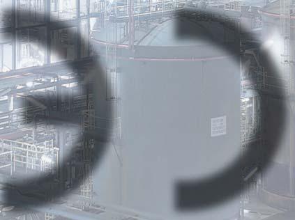
13 Principles of Explosion-Protection Gas-Ex-areas 1 Examples of applications and the classification of suitable equipment: Gas-Ex-areas Gas-Ex-areas Zone 0 Zone 0 mainly encompasses areas such as the inside of enclosed containers, pipes and apparatus that contain flammable liquids. Here the respective operating temperature lies above the flash point. The hazardous area is above the surface of the liquid and not in the liquid. Most gases of flammable liquids are heavier than air and spread in a similar way to liquids. Cavities such as pits or pump sumps can usually accommodate these explosive gases for longer periods, so that it is also necessary to expect a Zone 0 area here. With equipment for Zone 0, ignition sources shall be protected against explosion even if the occurrence of failures is only rare. Hence, the equipment shall satisfy the following requirements: Should one type of protection fail or should two faults occur simultaneously, sufficient protection against explosion shall still be ensured. The constructional requirements DIN EN (VDE 0170/0171/Part 12-1) state that the necessary explosion protection is attained if the equipment is built in accordance with the Zone 1 type of protection ia to EN , Intrinsic Safety, or satisfies the requirements of two types of protection of the series EN 60079, which are effective independently of each other. For this reason, for example, flameproof luminaires were additionally pressurised or intrinsically safe apparatus in the type of protection ib potted. According to Directive 2014/34/EU, equipment for Zone 0 shall satisfy the requirements for Category 1G. In Zone 0 the hazard of an ignition due to electrostatic charges, even on rare occasions, shall be safely excluded. For this reason, the requirements according to EN for equipment for use in Zone 0 exceed those for equipment for Zone 1 by far. Zone 1 Flammable or explosive substances are made, processed or stored in Zone 1. This includes the proximity of loading flap or filling and discharging facilities, the vicinity of fragile equipment, pipes and glands on pumps and slides that do not seal adequately. It is likely that an ignitable concentration will occur during normal operation. Ignition sources that occur during normal, trouble-free operation and those that usually occur in the event of operating disturbances shall be safely prevented. Zone 2 Zone classification example: Loading/discharging flammable liquids from a road transporter tanker without stand-alone ventilation. The chapter Electrical equipment for use in hazardous areas describes the individual types of protection. According to Directive 2014/34/EU, Zone 1 equipment shall satisfy the requirements for Category 2G. Zone 2 Zone 2 encompasses areas around Zone 0 and Zone 1, as well as areas around flanged joints on pipes in enclosed rooms. Furthermore, it includes such areas in which, due to natural or forced ventilation, the lower explosive limit is only attained in exceptional cases, such as the environment of outdoor installations. Flammable or explosive substances are manufactured or stored in Zone 2. The probability of the occurrence of an ignitable concentration is rare and, if one occurs, it only persists for a short period. During normal, trouble-free operation, ignition sources shall be safely prevented. According to Directive 2014/34/EU, equipment for Zone 2 shall satisfy the requirements for Category 3G. In addition, all equipment that satisfies the requirements for equipment for use in Zone 0 and Zone 1 is, of course, permitted. Example for a Zone 0 application: The inside of a flat-bottom tank of an oil terminal EATON 11


14 1 Principles of Explosion-Protection Dust-Ex-areas Dust-Ex-Areas Zone 21 Among others, Zone 21 encompasses mills, warehouses for coal or grain, and the area surrounding filling stations. Here, for example, explosive clouds of dust can develop due to the occasional escaping of dust from the opening. The risk of hazards due to dust deposits is often underestimated. Zone 20 Zone 20 mainly encompasses areas inside closed containers, pipes and apparatus in which combustible dust in the form of a cloud is present continuously or for long periods or frequently. With equipment for Zone 20, ignition sources shall be protected against explosions, even if the occurrence of a malfunction is rare. For this reason, equipment shall fulfil the following requirement: In the event of the failure of one type of protection or the simultaneous occurrence of two malfunctions, it is necessary to ensure adequate explosion protection. According to Directive 2014/34/EU, equipment for use in Zone 20 shall satisfy the requirements for Category 1D. Explosive dust/air mixtures can develop due to the formation of a smoulder spot or of a low temperature carbonization gas, as well as due to the deflagration of a low temperature carbonization gas or the whirlingup of dust caused by glowing combustion. Ignition sources that occur during normal, trouble-free operation and those that normally occur in the event of malfunctions shall be safely prevented. The individual types of protection are described in the chapter Electrical equipment for use in hazardous areas. According to Directive 2014/34/EU equipment for Zone 21 shall satisfy the requirements for Category 2D Example of dust-ex-zone 21: Explosion-protected terminal box Zone 22 In Zone 22, under normal operating conditions it is unlikely that an explosive dust/air mixture will occur. An explosive atmosphere is only to be expected in the event of malfunctions, e.g. due to whirled-up dust. Ignition sources shall be safely prevented during normal, trouble-free operation. According to Directive 2014/34/ EU, equipment for Zone 22 shall satisfy the requirements for Category 3D. Detailed information on all zones can be found in the chapter Installation and operation of electrical installations in hazardous areas. 12 EATON
 was the basis for the free movement of goods within the European economic area.")
15 European Ex-Directives European Ex-Directives 2 European Ex-Directives Free movement of goods within the European Community Article 100 of the treaty establishing the EEC (European Economic Community) was the basis for the free movement of goods within the European economic area. In 1975, to implement this article, the Council of the European Community issued the Explosion Protection Framework Directive (Directive 76/117/EEC). The issue of Directive 79/116/EEC by the European Commission concretised this basis and established a first legal basis. A series of European standards for explosion- protected apparatus was drawn up by the European Standards Committee for electrical apparatus (CENELEC) to provide the basis for the enforcement of the requirements. In Germany these European standards, EN to EN 50020, were adopted as VDE standards in the national standards. Directive 79/196/EEC was restricted to explosion-protected electrical equipment and the regulations that were required for the free movement of goods. By strict reference to the European standards, the normative basis for the certification of explosion-protected electrical apparatus was regulated by notified bodies. This symbol was specified as the distinctive mark for the placing of explosion-protected electrical equipment on the market throughout the community: Directive 94/9/EC of the European Parliament and Council dated st ATEX Directive The purpose of this directive was the approximations of the laws of the member states of the European Union for equipment and protective systems intended for use in potentially explosive atmospheres. As of it replaced all previous directives on explosion protection on a European level. The directive, also known as the ATEX directive, applied to equipment and protective systems that were intended for use in potentially explosive atmospheres. Safety devices and control systems for use outside of potentially explosive atmospheres also came under this directive. This also applied when such devices were required for the safe operation of equipment and protective systems in hazardous areas or contributed to it, Furthermore, the directive now directly included fundamental safety requirements for explosion-protected equipment. This directive, which applied to both electrical and mechanical equipment, encompassed requirements relating to the approval of equipment and the requisite quality assurance systems. These requirements are graduated according to the equipment category. As this new directive was drawn up according to the new approach of the EC, it also introduced the Declaration of Conformity to be issued by the manufacturer for explosionprotected equipment and the CE marking of products. Directive 2014/34/EU of the European Parliament and Council dated nd ATEX Directive Directive 94/9/EC had to be adapted to Resolution No. 768/2008/EC. This resolution required a common legal framework for the marketing of products and contains general principles and reference provisions that are to be applied in all sector-specific legal acts. It was, therefore, a common basis for a revised or new version of existing legal provisions. This new ATEX directive came into effect on , with a two-year transitional period. However, this did not mean that, as was the case with the transition to the 1st ATEX directive, both directives could be applied simultaneously. On the part of the European Commission only a legal certainty was provided that, when the transition period expired, the new directive only in the announced form was to be applied. Thus, the manufacturers were given the opportunity to adapt their directive-specific documents and papers within this two year period. In the case of the notified bodies, this meant, for example, that they had to complete the designation procedure for the new ATEX directive within these two years. The major changes only concern formal and legal aspects. No changes were made to the basic health and safety requirements or the type and content of the conformity assessment procedure. Thus, for example, an EC Type Examination Certificate according to Directive 94/9/EC can be used to issue a new CE Declaration according to Directive 2014/34/EU. In accordance with Article 41, 2, the issue of a new EU Type Examination Certificate according to the new directive is not necessary. Directive 94/9/EC could be applied for the last time on As of only the new ATEX directive 2014/34/EU applies. EATON 13
16 2 European Ex-Directives ATEX directive 2014/34/EU ATEX Directive 2014/34/EU Directive 2014/34/EU applies to products, i.e. equipment and protective systems intended for use in potentially explosive atmospheres, with the following definitions, which are new in part: a) Equipment means machines, apparatus, fixed or mobile devices, control components and instrumentation thereof and detection or prevention systems which, separately or jointly, are intended for the generation, transfer, storage, measurement, control and conversion of energy and/or the processing of material and which are capable of causing an explosion through their own potential sources of ignition. b) Protective systems means devices other than components of equipment which are intended to halt incipient explosions immediately and/or to limit the effective range of an explosion and which are separately made available on the market for use as autonomous systems. c) Components means any item essential to the safe functioning of equipment and protective systems but with no autonomous function. This Directive shall not apply to: medical devices intended for use in a medical environment; equipment and protective systems where the explosion hazard results exclusively from the presence of explosive substances or unstable chemical substances; equipment intended for use in domestic and non-commercial environments where potentially explosive atmospheres may only rarely be created, solely as a result of the accidental leakage of fuel gas; personal protective equipment as covered by Directive 89/686/EEC; seagoing vessels and mobile offshore units together with equipment on board such vessels or units; means of transport, i.e. vehicles and their trailers intended solely for transporting passengers by air or by road, rail or water networks, as well as means of transport in so far as such means are designed for transporting goods by air, by public road or rail networks or by water. Vehicles intended for use in a potentially explosive atmosphere shall not be excluded from the scope of this Directive. d) making available on the market means any supply of a product for distribution, consumption or use on the Union market in the course of a commercial activity, whether in return for payment or free of charge; e) placing on the market means the first making available of a product on the Union market; f) manufacturer means any natural or legal person who manufactures a product or has a product designed or manufactured, and markets that product under his name or trade mark or uses it for his own purposes. Structure and content of Directive 2014/34/EU Chapter 1 General Provisions (Article 1-5) Chapter 2 Obligations of economic operators (Article 6-11) Chapter 3 Conformity of the product (Article 12-16) Chapter 4 Notification of conformity assessment bodies (Article 17-33) Chapter 5 Union market, surveillance and control of products entering the Union market and Union safeguard procedure (Article 34-38) Chapter 6 Committee, transitional and final provisions (Article 39-45) Annex I Criteria determining the classification of equipment groups into categories Annex II Essential health and safety requirements relating to the design, and construction of equipment and protective systems for use in potentially explosive atmospheres Annex III Module B: EU-Type Examination Annex IV Module D: Conformity to type based on quality assurance of the production process Annex V Module F : Conformity to type based on product verifications Annex VI Module C1: Conformity to type based on internal production control plus supervised product testing Annex VII Module E: Conformity to type based on product quality assurance Annex VIII Module A: Internal production control Annex IX Module G: Conformity based on unit verification Annex X EU Declaration of Conformity Annex XI Part A: Repealed Directive with a list of the successive amendments thereto (referred to in Article 43) Part B: Time limits for transposition into national law and dates of application (referred to in Article 43) Annex XII Correlation table 14 EATON
17 European Ex-Directives ATEX directive 2014/34/EU 2 Essential health and safety requirements The requirements relating to equipment and protective devices are divided up into general requirements and supplementary requirements, whereby, above all, the supplementary requirements are to take both existing and potential hazards into consideration. This means that the equipment and protective systems shall satisfy one or more requirements at the same time, inasmuch as this is necessary for their correct operation or their intended use. Adherence to the health and safety protection requirements is absolutely essential to guarantee the safety of equipment and protective devices. These requirements shall be implemented with prudence in order to fulfil the latest technological developments at the time of making equipment available on the market. This directive only defines general basic requirements. In order to make it easier to furnish proof that a piece of equipment or a protective system conforms to these requirements, uniform standards have been established on a European level. If standards are published by the European Commission in the Official Gazette of the European Communities as assigned to a given directive, they are valid as so-called harmonized standards. If a product meets the requirements of the harmonized standards, the essential requirements of the directive are deemed to be fulfilled (presumption of conformity). If necessary, this list in the official gazette is adapted in line with the latest versions of the standards. These standards are, in principle, prepared by the European Committee for Standardization (CEN) and the European Committee for Electro-technical Standardization (CENELEC). In the field of explosion protection the standardization is largely carried out by Technical Committee TC31, Equipment for explosive atmospheres, of the International Electro-technical Commission (IEC). Equipment groups and equipment categories Equipment is subdivided into groups and categories: Equipment group I applies to equipment intended for use in underground parts of mines as well as those parts of surface installations of such mines that can be endangered by firedamp and/or combustible dust. Equipment group II applies to equipment for use in the remaining areas that can be at risk due to an explosive atmosphere. Categories See adjacent tables Making available on the market and commissioning of products The member states must not forbid, restrict or impede the making available on the market and commissioning of equipment, protective systems and devices that conform to the terms of this directive. Similarly, the making available on the market of components accompanied by a certificate of conformity according to Article 13, 3 of Directive 2014/34/EU shall not be forbidden, restricted or impeded if they are to be built into a piece of equipment or a protective system in line with this directive. The EU member states assume conformity with this directive and with the conformity assessment procedures if the apparatus, protective systems and devices are accompanied by the EU Certificate of Conformity and if the products are provided with the CE marking. Products that do not yet meet the requirements of this directive may be displayed at exhibitions, fairs and demonstrations if a visible sign clearly indicates that it will not be possible to purchase the product until compliance with the directive has been ensured. Classification of explosion protected apparatus in equipment groups and categories according to 2014/34/EU Equipment Group I for mines endangered by firedamp. The equipment Group I is subdivided into the Categories M1 and M2: M1 M2 1 The equipment in this category is intended for use in both underground parts of mines and those parts of surface installations of such mines that are endangered by firedamp and/or combustible dust. The equipment shall continue to remain functional even in the event of rare incidents relating to the equipment with an explosive atmosphere present, and feature such protective measures that in the event of failure of one means of protection, at least an independent second means provides the requisite level of protection, or the requisite level of protection is assured in the event of two faults occurring independently of each other. The equipment in this category is intended for use in both underground parts of mines and those parts of surface installations of such mines that are endangered by firedamp and/or combustible dust. If an explosive atmosphere occurs, it must be possible to switch off the equipment. The constructional explosion-protection measures ensure the required degree of safety during normal operation, even under severe operating conditions and, in particular, in cases of rough handling and changing environmental influences. Equipment Group II for all other hazardous areas The equipment Group II is subdivided into the Categories 1, 2 and 3: 2 3 The equipment in this category is intended for use in areas in which an explosive atmosphere is present continuously or for long periods or frequently. Even if equipment failures only occur infrequently, the equipment must ensure the required degree of safety and feature such explosion protection measures that if one constructional protective measure fails, at least one other independent constructional protective measure ensures the required degree of safety, or if two independent faults occur in combination, the required degree of safety is still ensured. The equipment in this category is intended for use in areas in which an explosive atmosphere occurs occasionally. Even in the case of frequent equipment failures or faulty conditions that are normally to be expected, the constructional explosion-protection measures ensure the required degree of safety. The equipment in this category is intended for use in areas in which no occurrence of an explosive atmosphere due to gases, vapours, mists or whirled-up dust is to be expected. If, however, it occurs, then in all probability only rarely or for a short period. During normal operation the equipment ensures the required degree of safety. EATON 15
18 2 European Ex-Directives ATEX directive 2014/34/EU Procedure for non-compliant (e.g. unsafe) products Should a member state or their market surveillance authorities discover that any equipment, protective systems or devices (products) with the CE marking are unsafe; it can withdraw these from the market and forbid their being made available on the market or commissioning, or restrict their free circulation. The member state is required to notify the commission of the European Union of such measures and to give the reasons for its decision. The commission will immediately contact the economic operators concerned (manufacturers, authorized persons, importers or retailers) and inform all member states if these measures are justified. Equipment, protective systems or devices (products) are deemed unsafe if, when used for their intended purpose, they represent an imminent danger to the safety of people, domestic animals or goods. According to Article 38 of the Directive, a product is formally deemed non-compliant if, for example: the CE marking has not been affixed; the specific marking of explosion protection, the symbols of the equipment-group and category and, where applicable, the other markings and information have not been affixed in violation of point of Annex II; the identification number of the notified body, where that body is involved in the production control phase, has been affixed wrongly or has not been affixed; the EU declaration of conformity or the attestation of conformity, as appropriate, does not accompany the product or has not been issued correctly; or the technical documentation is not available or not complete. Marking In accordance with Annex II, Point of the Directive, each piece of equipment and each protective system shall be marked in a clear and indelible manner with the following minimum particulars: name, registered trade name or registered trade mark, and address of the manufacturer, (The contact data shall be given in a language that is easily comprehensible for the end users and the market surveillance authorities.) CE marking designation of series or type batch or serial number, if any, year of construction the specific marking of explosion protection followed by the symbol of the equipment group and category, for equipment-group II, the letter G (concerning explosive atmospheres caused by gases, vapours or mists), and/or the letter D (concerning explosive atmospheres caused by dust). Furthermore, and where necessary, they shall also be marked with all information essential to their safe use Conformity assessment procedures Depending upon the conformity assessment procedure to be applied, a notified body can be active during the design and engineering phase, during the production phase or during both phases. The applicable evaluation procedure is laid down in the Directive according to the product, the group and the equipment category. Equipment groups I and II, equipment categories M1 and 1 In order to be permitted to affix the CE mark to his product, the manufacturer must arrange for the following procedures to be carried out: EU-type examination by a notified body and either an audit of the quality assurance for the production process or an audit of the products. Equipment groups I and II, equipment categories M2 and 2 In the case of internal combustion motors and electrical equipment, in order to be permitted to affix the CE marking to the product, the manufacturer shall arrange for the following procedures to be carried out and/or ensure the following measures: EU-type examination by a notified body and either ensure constructional conformity or verification of the quality assurance of the products. In the case of other equipment in these groups and categories, the internal production control procedure shall be applied, whereby the technical documentation shall be submitted to a notified body in accordance with Article 13, 1, Clause b) ii). Equipment group II, equipment category 3 In order to be permitted to affix the CE mark to the product, the manufacturer shall apply the internal production control procedure. Declaration of Conformity In order to make products available on the market within the EU, the EU Declaration of Conformity shall be included with all products or batches of identical products. This does not apply to the report, if available, issued by the notified body as part of the audit of the quality assurance system of the manufacturer or the EU-Type Examination Certificate. SERIES CEAG D Eberbach BVS 16 ATEX E 123 / IECEx BVS IP66/67 II 2G Ex db eb mb ib IIC T4 Gb Ta= -25 C bis +55 C II 2D Ex tb IIIC T80 C Db AC: V 50-60Hz DC: V Lampe: G13-81-IEC Snr.: D Made in Germany Example for a type label according to the latest standards and directive 2014/34/EU 16 EATON


19 European Ex-Directives ATEX directive 2014/34/EU 2 Explosion-protected linear light fitting type ellk 92 LED 800 with operating instruction and Declaration of Conformity These operating instructions and safety information as well as all markings shall be explicit, easily comprehensible and clearly visible. The maintenance instructions for use by the specialist personnel employed by the manufacturer or his authorized representative established in the Community may be drawn up in a single community language that is understood by this personnel. The operating instructions contain the drawings and diagrams that are necessary for the putting into service, maintenance, inspection, checking of correct operation and, when appropriate, repair of equipment and protective systems, together with all useful instructions, in particular with regard to safety. With regard to safety aspects, the documentation describing the equipment or protective systems shall not conflict with the operating instructions. Instructions According to Annex II, point of the Directive, all equipment and protective systems shall be accompanied by instructions, including at least the following particulars: a recapitulation of the information with which the equipment or protective system is marked, except for the batch or serial number, and, where appropriate, any additional information to facilitate maintenance (e.g. address of the importer or service workshop, etc.); instructions for safe: - putting into service, - use, - assembling and disassembling, - maintenance (servicing and emergency repairs), - installation, - adjustment; where necessary, an indication of the danger areas in front of pressure-relief devices, where necessary, training instructions, details which allow a decision to be taken beyond any doubt as to whether an item of equipment in a specific category or a protective system can be used safely in the intended area under the expected operating conditions, electrical and pressure parameters, maximum surface temperatures and other limit values; where necessary, special conditions of use, including particulars of possible misuse which experience has shown might occur; and where necessary, the essential characteristics of tools which may be fitted to the equipment or protective system. The operating instructions shall be drawn up by the manufacturer or his authorized representative established in the community in one of the community languages in accordance with the decision of the respective member state and it shall be easily comprehensible for the users and other end users. EATON 17

20 2 European Ex-Directives European directives CE-sign CE-marking The manufacturer shall affix the CE marking to products that fall within the scope of given directives. This applies to products that are covered by the directives according to the new concept and include requirements relating to the technical properties of products. These EU directives constitute binding regulations of the European Union. This means that compliance with these requirements is the condition for marketing the products in Europe. When the CE marking is affixed to a product, the conformity of the product with the relevant basic requirements of all directives applicable to the products is confirmed. The marking is, therefore, an imperative requirement for the making available on the market of products within the Community, as well as in the country of origin. Directive 2006/42/EC: Machinery Directive Mechanical engineering is an important technical subsector and one of the industrial core areas of the economy in the Community. The social costs caused by the numerous accidents that occur as a result of the use of machinery can be lowered if the safety aspect is taken into consideration during the design and construction of machines and if the machines are installed and maintained correctly. If the hazards presented by machinery stated in Annex I of the Directive are covered in total or partially by other Community Directives, this directive does not apply to this machine and the hazards or no longer applies from the beginning of the application of these other directives. Annex I, states that; Machinery must be designed and constructed in such a way as to avoid any risk of explosion posed by the machinery itself or by gases, liquids, dust, vapours or other substances produced or used by the machinery. Machinery must comply, as far as the risk of explosion due to its use in a potentially explosive atmosphere is concerned, with the provisions of the specific Community Directives. Directive 2014/30/EU: EMC-Directive Subject matter of this directive is the electromagnetic compatibility of equipment. This directive shall be applied to all products that can cause electromag netic interferences or whose operation can be affected by these interference. It is intended to ensure the functioning of the single market for equipment by specifying an appropriate level of electromagnetic compatibility. Directive 2014/35/EU: Low Voltage Directive The aim of this directive is to ensure that electrical equipment on the market meets the requirements that guarantee a high protective level with regard to the health and safety of people, domestic animals and livestock and with regard to property, while guaranteeing the functioning of the single market. The Directive shall apply to electrical equipment designed for use with a voltage rating of between 50 V and 1000 V for alternating current and between 75 V and 1500 V for direct current, with the exception of the electrical equipment and areas listed in Annex II, i.a. electrical equipment for use in explosive atmospheres. Directive 1999/5/EC: Radio and Telecommunications Terminal Equipment (RTTE) This directive regulates the making available on the market, free trade and putting into operation of radio installations and telecommunications transmission devices within the Community. Directive 89/686/EEC: Personal Protective Equipment (PPE) For the purposes of this directive, PPE is any device or means that is intended to be worn or held by a person and protect this person against one or more risks that might endanger his health or safety. Directive 2014/68/EU: Pressure Equipment Directive (PED) This directive applies to the design, manufacture and conformity assessment of pressure equipment and assemblies with a maximum permissible pressure (PS) of more than 0.5 bar. This directive does not apply to equipment that, according to Article 13 of this directive, would, at most, come under Category I and is covered by one of the clauses of Directive 2014/34/EU. Directive 2014/29/EU: Simple Pressure Vessels (SPVD) This directive applies to vessels that are manufactured in series. The CE marking is only meant as evidence of conformity with the directives for the supervising authorities and is not a quality mark. In addition to the CE marking, the manufacturer shall also prepare a Declaration of Conformity for the product. This Declaration of Conformity shall clearly indicate which directive was applied and which standards were taken into account for the verification of conformity. The following directives are also of particular importance for electrical equipment: 18 EATON
21 European Ex-Directives Directive 1999/92/EC 2 Directive 1999/92/EC Directive 1999/92/EC of the European Parliament and Council dated It defines the minimum requirements for the improvement of the health and safety protection of employees potentially at risk due to an explosive atmosphere and is also referred to as the European Workplace Directive. Explosion-protection is of particular importance to safety. Explosions endanger the lives and health of workers as a result of the uncontrolled effects of flame and pressure, the presence of noxious reaction products and consumption of the oxygen in the ambient air which workers need to breathe; For this reason, in order to establish a coherent strategy for the prevention of explosions at the workplace, organisational measures have to be taken. Directive 89/391/EEC requires the employer to take the necessary measures for the health and safety protection of employees, including measures for the prevention of occupational hazards, to inform and instruct, and to provide a suitable organization and the necessary means. The directive was issued in accordance with Article 137 of the treaty establishing the EEC and is, as such, only a minimum requirement. It states explicitly that any provisions issued on the basis of this article shall not prevent the member states from maintaining or taking more stringent protective measures that are compatible with the treaty. Scope This Directive, which is the 15 th individual Directive within the meaning of Article 16(1) of Directive 89/391/EEC, lays down minimum requirements for the health and safety protection of workers potentially at risk from explosive atmospheres. It does not apply to: a) areas used directly for and during the medical treatment of patients; b) the use of appliances burning gaseous fuels in accordance with Directive 90/396/EEC (2); c) the manufacture, handling, use, storage and transport of explosives or chemically unstable substances; d) mineral-extracting industries covered by Directive 92/91/EEC or Directive 92/104/EEC; e) the use of means of transport by land, water and air, to which the pertinent provisions of the international agreements (e.g. ADNR, ADR, ICAO, IMO, RID), and the Community Directives for the implementation of those agreements apply. Means of transport intended for use in a potentially explosive atmosphere shall not be excluded. Reduction and assessment of explosion risks It is the duty of the employer to carry out measures in the following order of precedence: 1. Where possible, the prevention of explosive atmospheres by the substitution of materials. 2. Prevention of the ignition of explosive atmospheres. 3. Mitigation of harmful effects. This concept is already known in Germany due to the explosion-protection directives of the employers liability insurance association and it has been put into practice for many years. The new aspect of this directive is the systematic method according to which the measures are laid down and documented. Structure of the directive 1999/92/EC Enacting part Section 1 Article 1-2 General Requirements Section 2 Article 3-9 Duties of employer 3: Prevent of and protection against explosions 4: Assessment of the explosion risks 5: General obligations 6: Coordination obligations 7: Areas with explosive atmospheres 8: Explosion-protection document 9: Special regulations relating to working materials and places of work Section 3 Article Other requirements Appendix I Classification of areas where explosive atmospheres may occur 1. Areas where explosive atmospheres may occur 2. Classification of hazardous areas Section II A Minimum requirements for the improvement of the safety and health protection of employees potentially at risk from explosive atmospheres 1. Organisational measures 2. Explosion-protection measures Section II B Criteria for the selection of equipment and protective systems Section II C Warning signs for marking areas where explosive atmospheres may occur After assessment of all the remaining explosion risks, whereby the interaction of installations, the materials being used, the processes and their possible interactions were taken into consideration, measures for the safety of employees at work must be laid down to ensure their health and safety at all times. Here special requirements are imposed regarding the coordination duties of the employer at the place of work Classification of hazardous areas The areas in which explosive atmospheres can occur are subdivided into zones according to the frequency and duration of the occurrence of explosive atmospheres. This classification determines the scope of the measures to be taken. Zone 0 A place in which an explosive atmosphere consisting of a mixture with air of flammable substances in the form of gas, vapour or mist is present continuously or for long periods or frequently. Zone 1 A place in which an explosive atmosphere consisting of a mixture with air or flammable substances in the form of gas, vapour or mist is likely to occur in normal operation occasionally. Zone 2 A place in which an explosive atmosphere consisting of a mixture with air of flammable substances in the form of gas, vapour or mist is not likely to occur in normal operation but, if it does occur, will persist for a short period only. EATON 19


22 2 European Ex-Directives Directive 1999/92/EG Zone 20 A place in which an explosive atmosphere in the form of a cloud of combustible dust in air is present continuously, or for long periods or frequently Zone 21 A place in which an explosive atmosphere in the form of a cloud of combustible dust in air is likely to occur in normal operation occasionally. Zone 22 A place in which an explosive atmosphere in the form of a cloud of combustible dust in air is not likely to occur in normal operation but, if it does occur, will persist for a short period only. Note: 1. Layers, deposits and accumulations of combustible dust that can form an explosive atmosphere shall be treated in the same way as any other cause. 2. Normal operation is the state in which installations are used within the rated parameters. Explosion protection document As part of his obligations, the employer shall ensure that a document (hereinafter referred to as the explosion protection document ) is drawn up and kept up to date. In particular, the explosion protection document shall demonstrate: that the explosion risks have been determined and assessed; that adequate measures are taken to fulfil the aims of this Directive; which areas which have been classified into zones in accordance with Annex I; the areas where the minimum requirements set out in Annex II apply; that the workplace and work equipment, including warning devices, are designed, operated and maintained with regard to due safety; and that, in accordance with Council Directive 89/655/EEC (1), arrangements have been made for the safe use of work equipment. The explosion protection document shall be drawn up prior to commencement of work. and shall be revised when the workplace, work equipment or organisation of the work undergoes significant changes, extensions or conversions. The employer may combine existing explosion risk assessments, documents or other equivalent reports produced under other Community acts. Annex II A Minimum requirements for the improvement of the health and safety protection of employees potentially at risk from explosive atmospheres. 1. Organisational measures Appropriate instruction of employees Written instructions and work release notes If necessary, written instructions for the work assignment Work release system for hazardous tasks Work release by authorized person 2. Explosion protection measures Rendering any escaped Ex atmosphere harmless Design according to the highest risk potential Avoidance of all ignition hazards (e.g. static charge of persons) Taking into operation if authorized in the explosion document Installation and operation according to the lowest explosion risk If necessary, warning of Ex atmosphere (visual/acoustical) Provision of escape facilities Initial inspection by qualified persons Measures for risk assessment Hazards due to power failures Safe reduction of stored energy Annex II B Criteria for the selection of equipment and protective systems: Unless otherwise specified in the explosion protection document, taking into account the risk evaluation, equipment and protective systems are selected in accordance with Directive 2014/34/EU Zone Category 0 or or 21 1 or 2 2 or 22 1, 2 or 3 Anex III Warning sign for marking areas in which explosive atmospheres may occur. 20 EATON

 and equipment protection levels")

23 Explosion-protected Electrical Equipment Basics 3 Electrical equipment for use in hazardous areas: Subdivision into groups Gap Basics General It would not be economical to build all explosion-protected electrical equipment in such a way that it can be used in all hazardous areas. Furthermore, there are also other boundary conditions that have to be taken into consideration, e.g. relating to the ignition temperature, flame transmission properties and the ignitability of the explosive substances. For the gradation or allocation to the required safety level for the respective application, it is subdivided into; Groups temperature classes (surface temperature) and equipment protection levels With all equipment it is necessary to observe the further subdivision into groups with regard to the risk of an electrostatic charge/discharge. In addition, hazards due to electromagnetic and optical radiation shall also be taken into account. Electrical equipment for use in gas Ex areas Group II Group II electrical equipment in is subdivided into A, B, and C. In the case of flameproof enclosures, the classification is based on the maximum experimental safe gap (MESG) and, in the case of intrinsically safe apparatus on the minimum ignition current (MIC). Group I: Electrical equipment for use in mines susceptible to firedamp such as coal mines Group II: Electrical equipment for use in explosive gas atmospheres Group III: Electrical apparatus for use in all explosive dust atmospheres Maximum experimental safe gap (MESG) Definition: The maximum gap of the joint between the two parts of the interior chamber of a test apparatus which, under specified conditions, when the internal gas mixture is ignited, prevents ignition of the external gas mixture by flame propagation through a joint measuring 25 mm in length. Apparatus for the experimental determination of the maximum safe gap (MESG) in accordance with IEC Joint width Groups A and B Flat joint Groups A, B and C Cylindrical joint Groups A, B and C Threaded joint - Different types of joint in practice: flanged joint cylindrical joint threaded joint Minimum ignition current (MIC) A minimum ignition energy is needed to ignite an explosive mixture. Due to an external ignition source, e.g. an electric spark, a high temperature develops in a small volume area of an explosive atmosphere. This then leads to combustion. The heat generated by the spark and the subsequent combustion heats the immediate layers, but, at the same time, energy is fed to the outside due to heat conduction. If the heat dissipation is greater than the quantity of heat that is supplied and generated, a propagation of the combustion to the surrounding volume areas is not possible. Only if, due to the external ignition source, the energy input is so great that the temperature of the surrounding layers rises above its ignition temperature, the combustion is propagated autonomously and an explosion occurs. Apparatus for the experimental testing of the minimum ignition current (MIC) Minimum ignition energy The smallest amount of electrical energy stored in a capacitor that, in the event of the discharge of this capacitor across a spark gap, is barely able to ignite the most easily ignitable fuel/air mixture at atmospheric pressure and room temperature. There is a certain relationship between the safe gap and the minimum ignition current ratio. In order to be able to classify gases and vapours to satisfy the explosion-protection requirements, it is, therefore, sufficient to determine just one of the two properties of most of the mixtures of gas and vapour with air that are used in industry. Groups Safe Gap in mm Minimum ignition current II A > 0,9 > 0,8 II B 0,5 to 0,9 0,45 to 0,8 II C < 0,5 < 0,45 This basic knowledge is used for the type of protection Intrinsic Safety. The electric ratings of a circuit are limited to such a degree that the minimum ignition energy required for an ignition is not attained. Ignition energy in relation to the concentration of a flammable substance in air EATON 21


24 3 Explosion-protected Electrical Equipment Basics Ignition temperature and temperature classes The maximum surface temperature of the electrical equipment, subject to the protective measures on the interior or exterior, must not attain the ignition temperature of the hazardous explosive atmosphere. The ignition temperature of a flammable substance is determined by means of a test apparatus and is defined as the lowest temperature on a heated wall at which the flammable substance will just ignite in the mixture with air. Temperature class Maximum permissible surface temperature of the equipment in C The ignition temperatures of the different explosive mixtures vary considerably. Whereas a mixture of air with town gas will only ignite at 560 C, a mixture of air and petrol will ignite at ca. 250 C. The data can be found in IEC To simplify matters, these different properties were classified and divided into temperature classes. Experimental determination of the ignition temperatures of flammable substances to IEC Ignition temperatures of the flammable substances in C T > 450 T > T > T > T > T 6 85 > Classification of gases and vapours in explosion groups and temperature classes T1 T2 T3 T4 T5 T6 Electrical equipment for use in areas with combustible dusts Group III The subdivision of Group III electrical equipment is based on the same principle as the subdivision of Group II electrical equipment, whereby the division into Groups A, B and C is based on the properties of the dust. Groups Substances IIIA combustible flyings IIIB non-conductive dusts IIIC conductive dusts Ignition sources Combustible dust can be ignited by electrical equipment in various ways: by equipment surface temperatures that are higher than the ignition or glow temperature of the respective dust. The temperature at which the dust ignites is dependent on the properties of the dust, on whether it is present in the form of a cloud or deposits, on the thickness of the layer and on the type of heat source; by sparks at electrical parts such as switches, contacts, commutators, brushes or similar; by the discharge of stored electro static energy; by radiated energy (e.g. electromagnetic radiation); by mechanic impact or friction sparks or a rise in temperature originating from the apparatus. Explosion-protected portable search light in the dust test chamber To avoid ignition hazards, it is necessary that: the temperature of any surfaces on which dust deposits can form or that can come into contact with a cloud of dust are kept at a temperature that is lower than the limiting temperatures laid down in EN ; all parts with electric sparks or with temperatures above the ignition or glow temperature of the dust are built into an enclosure that prevents the ingress of dust in a suitable manner, or the energy of the electric circuits is limited to such a degree, that sparks or temperature that could ignite com bustible dust are avoided; all other ignition sources are avoided. I Methane Acetone Ethane Ethylacetate Ammonia Benzol Acetic acid Carbon oxyde Methanol Propane Toluene II A Ethylalcohol i-amylacetate n-butane n-butylalcohol Petrol Diesel fuel Aviation fuel Heating oils n-hexane Acetaldeyde- Ethylether II,B Town gas (lamp gas) Ethylene II C Hydrogen Acetylene Carbon disulphide 22 EATON


25 Explosion-protected Electrical Equipment Equipment protection level EPL 3 Equipment protection level EPL An alternative method for the risk assessment taking the Equipment Protection Level for Ex-equipment into account. Historical background Hazardous areas are divided into zones according to the degree of hazard. The degree of hazard is defined according to the probability of the occurrence of an explosive atmosphere. Generally, neither the potential consequences of an explosion nor other factors, such as the toxicity of materials, are taken into account. A true risk assessment would consider all factors. Historically, the selection of equipment for each zone is based on a firm link between the zone and the type of protection to be applied. Not all types of protection provide the same degree of safety against the possibility of the occurrence of an ignitable state. For this reason, specific types of protection have been allocated to specific zones. This was carried out on the statistical basis that - depending on the probability or frequency of the occurrence of an explosive atmosphere- the required level of safety against the probability of the presence of an ignition source and the probability of the occurrence of an explosive atmosphere has be adapted accordingly. At a very early stage the type of protection Intrinsic Safety, which was used for the instrumentation and control technology, was subdivided into various safety categories while maintaining the general explosion protection measures (see EN for details). These categories were then assigned directly to zones. As an alternative method to the prescriptive and relatively rigid approach of the association of equipment to zones, a concept that was uncoupled from hazardous areas was introduced for the assessment of hazards for the selection of Ex equipment. The ignition hazard posed by the equipment itself was the defining characteristic, whereby it did not matter which protection measure was being applied. To simplify this, a system of protections levels relating to the equipment was introduced. The concept of protective levels relating to the equipment was first implemented in the European directive 94/9/EC and described as categories. This concept was adopted in the standards as Equipment Protection Levels (EPL). The Equipment Protection Level (EPL) is the level of protection assigned to equipment based on its likelihood of becoming a source of ignition and distinguishing the differences between explosive gas atmospheres, explosive dust atmos pheres, and the explosive atmospheres in mines susceptible to firedamp. Zone classification / Equipment protection level For most of the situations with the typical possible consequences of an occurring explosion a standard assignment from Zone to equipment protection level is possible. Minimum requirements for equipment Substance Period of presence of the combustible substances Zone Directive 2014/34/EU Equipment group Equipment category Standard IEC/EN Group Equipment protection level EPL Protection level Continuously for long periods or frequently Zone 0 II 1 G II Ga very high Gas, mist, vapour Occasional occurrence Zone 1 II 2 G II Gb high Not likely, but if it occurs only rarely and for a short period Zone 2 II 3 G II Gc enhanced Continuously for long periods or frequently Zone 20 II 1 D III Da very high Dust Occasional occurrence Zone 21 II 2 D III Db high Not likely, but if it occurs only rarely and for a short period Zone 22 II 3 D III Dc enhanced Methane, coal dust Mining I M1 I Ma very high Mining I M2 I Mb high EATON 23


 EPL Ga Equipment for explosive gas atmospheres, having a very high level of protection, which is not a source of ignition in normal operation, during expected")
26 3 Explosion-protected Electrical Equipment Equipment protection level EPL Mines susceptible to firedamp (Group I) EPL Ma Equipment for installation in a mine susceptible to firedamp, having a very high level of protection, which has sufficient security that it is unlikely to become an ignition source in normal operation, during expected malfunctions or during rare malfunctions, even when left energized in the presence of an outbreak of gas. EPL Mb Equipment for installation in a mine susceptible to firedamp, having a high level of protection, which has sufficient security that it is unlikely to become a source of ignition in normal operation or during expected malfunctions in the time span between there being an outbreak of gas and the equipment being de-energized. Picture: Ruhrkohle-AG Gases (Group II) EPL Ga Equipment for explosive gas atmospheres, having a very high level of protection, which is not a source of ignition in normal operation, during expected malfunctions or during rare malfunctions EPL Gb Equipment for explosive gas atmospheres, having a high level of protection, which is not a source of ignition in normal operation or during expected malfunctions EPL Gc Equipment for explosive gas atmospheres, having an enhanced level of protection, which is not a source of ignition in normal operation and which may have some additional protection to ensure that it remains inactive as an ignition source in the case of regular expected occurrences (for example failure of a lamp) Dust (Group III) EPL Da Equipment for explosive dust atmospheres, having a very high level of protection, which is not a source of ignition in normal operation, during expected malfunctions, or during rare malfunctions. EPL Db Equipment for explosive dust atmospheres, having a high level of protection, which is not a source of ignition in normal operation or during expected malfunctions. EPL Dc Equipment for explosive dust atmospheres, having an enhanced level of protection, which is not a source of ignition in normal operation and which may have some additional protection to ensure that it remains inactive as an ignition source in the case of regular expected occurrences (for example failure of a lamp) For a large majority of situations with the typical possible consequences of the occurrence of an explosion, a standard allocation of zones to equipment protection levels is possible. 24 EATON
27 Explosion-protected Electrical Equipment Equipment protection level EPL 3 Electrical types of protection for explosive atmospheres due to flammable gases, vapours and mists Type Protection level Type of protection Group Equipment category Equipment protection level (EPL) CENELEC /IEC standard d da Flameproof enclosure II 1 G Ga EN / IEC d db Flameproof enclosure II 2 G Gb EN / IEC Protection concept Explosion containment, prevention of flame transmission Explosion containment, prevention of flame transmission d dc Flameproof enclosure II 3 G Gc EN / IEC Explosion containment, prevention of flame transmission p pxb pyb Pressurised enclosure II 2 G Gb EN / IEC Exclusion of Ex-atmosphere p pzc Pressurised enclosure II 3 G Gc EN / IEC Exclusion of Ex-atmosphere q Powder filling II 2 G Gb EN / IEC Prevention of explosion diffusion o ob Liquid immersion II 2 G Gb EN / IEC Exclusion of Ex-atmosphere o oc Liquid immersion II 3 G Gc EN / IEC Exclusion of Ex-atmosphere e eb Increased safety II 2 G Gb EN / IEC No arcs, sparks or hot surfaces e ec Increased safety II 3 G Gc EN / IEC No arcs, sparks or hot surfaces i ia Intrinsic safety II 1 G Ga EN / IEC i ib Intrinsic safety II 2 G Gb EN / IEC i ic Intrinsic safety II 3 G Gc EN / IEC p/v Pressurised enclosure/ventilation II 2 G Gb EN IEC Limitation of spark energy and surface temperature Limitation of spark energy and surface temperature Limitation of spark energy and surface temperature Exclusion of Ex-atmosphere / dilution na Non-sparking equipment II 3 G Gc EN / IEC No arcs, sparks or hot surfaces nc Enclosed equipment II 3 G Gc EN / IEC nr Restricted breathing enclosure II 3 G Gc EN / IEC Explosion containment, prevention of flame transmission Exclusion of Ex-atmosphere for a limited period m ma Encapsulation II 1 G Ga EN / IEC Exclusion of Ex-atmosphere m mb Encapsulation II 2 G Gb EN / IEC Exclusion of Ex-atmosphere m mc Encapsulation II 3 G Gc EN / IEC Exclusion of Ex-atmosphere i Intrinsic system II 2 G Gb EN / IEC Limitation of spark energy and surface temperature op is op is op is op pr op sh op pr op sh Equipment with protection level (EPL) Ga Inherent safe optical radiation Inherent safe optical radiation inherent safe optical radiation Safe/interlocked optical radiation Safe/interlocked optical radiation II 1 G 1 G/2 G Ga Ga/Gb EN / IEC Double protection concept II 1 G Ga EN / IEC Limitation of radiation energy II 2 G Gb EN / IEC Limitation of radiation energy II 3 G Gc EN / IEC Limitation of radiation energy II 2 G Gb EN / IEC II 3 G Gc EN / IEC Limitation or containment of radiation energy Limitation or containment of radiation energy s sa Special protection n.a. n.a. Ga IEC Special measures s sb Special protection n.a. n.a. Gb IEC Special measures s sc Special protection n.a. n.a. Gc IEC Special measures EATON 25
28 3 Explosion-protected Electrical Equipment Equipment protection level EPL Electrical types of protection for explosive atmospheres due to combustible dust Type p p Protection level pxb pzc Type of protection Pressurised enclosure Pressurised enclosure Group Directive Standard Equipment category Equipment protection level (EPL) CENELEC /IEC standard II III 2 D Db EN / IEC II III 3 D Dc EN / IEC i ia Intrinsic safety II III 1 D Da EN / IEC i ib Intrinsic safety II III 2 D Db EN / IEC i ic Intrinsic safety II III 3 D Dc EN / IEC m ma Encapsulation II III 1 D Da EN / IEC m mb Encapsulation II III 2 D Db EN / IEC m mc Encapsulation II III 3 D Dc EN / IEC op is op is op is op pr op sh op pr op sh t t ta tb Inherent safe optical radiation Inherent safe optical radiation Inherent safe optical radiation Safe/interlocked optical radiation Safe/interlocked optical radiation Protection by enclosure Protection by enclosure II III 1 D Da EN / IEC II III 2 D Db EN / IEC II III 3 D Dc EN / IEC II III 2 D Db EN / IEC II III 3 D Dc EN / IEC Protection concept Exclusion of Ex-atmosphere Exclusion of Ex-atmosphere Limitation of spark energy and surface temperature Limitation of spark energy and surface temperature Limitation of spark energy and surface temperature Exclusion of Ex-atmosphere Exclusion of Ex-atmosphere Exclusion of Ex-atmosphere Limit of radiation energy Limit of radiation energy Limit of radiation energy Limitation or containment of radiation energy Limitation or containment of radiation energy II III 1 D Da EN / IEC Exclusion of dust II III 2 D Db EN / IEC Exclusion of dust t tc Protection by enclosure II III 3 D Dc EN / IEC Exclusion of dust s sa Special protection III n.a. Da IEC Special measures s s sb sc Special protection Special protection III n.a. Db IEC Special measures III n.a. Dc IEC Special measures 26 EATON

29 Explosion-protected Electrical Equipment Type of protection to EN Type of protection to EN Explosive atmospheres Part 0: Equipment General requirements Electrical equipment for use in explosive atmosphere shall meet the general requirements of EN and the specific requirements of the type of protection in which it is designed. Under some circumstances, particularly harsh operating conditions, the effects of humidity, high ambient temperatures and other special demands require additional measures. Some of the main points are listed below: Equipment grouping Electrical equipment for explosive atmospheres is divided into the following groups: Electrical equipment of Group I is intended for use in mines susceptible to firedamp. Electrical equipment of Group II is intended for use in areas where an explosive gas atmosphere is to be expected, other than mines susceptible to firedamp. Electrical equipment of Group II is subdivided according to the nature of the explosive atmosphere for which it is intended. Group II subdivisions IIA, a typical gas is propane IIB, a typical gas is ethylene IIC, a typical gas is hydrogen Electrical equipment of Group III is intended for operation in areas with an explosive dust atmosphere, other than mines susceptible to firedamp. Electrical equipment of Group III is subdivided according to the nature of the explosive atmosphere for which it is intended Group III subdivisions IIIA, combustible flyings IIIB, non-conductive dust IIIC, conductive dust Table 34/1: Ambient temperatures in service and additional marking Electrical equipment Temperatures Electrical equipment shall be designed for use in a normal ambient temperature range of -20 to +40 C (see table 34/1). Mechanical strength of equipment The mechanical strength, suitability for the intended operating temperature range and the resistance to ageing of the materials used are verified by climatic conditioning and tests for resistance to impact and drop tests(see table 34/1). Electromagnetic and ultrasonic energy-radiating equipment In order to prevent the ignition of an explosive mixture, the signals emitted from equipment shall be below the values stated in the standard. The specified limiting values shall also apply to lasers and other continuous light sour ces. Enclosures and parts of enclosures If plastics and light alloys are used, special requirements listed in the standard that apply specifically to enclosures shall be met. Ambient temperature in service Normal Maximum: +40 C Minimum: 20 C Special Table 34/2 Specified by the manufacturer To prevent an electrostatic charge, in the case of plastic enclosures, a material with a surface resistance of < 1 GOhm is used if the area specified in the standard is exceeded. Additional marking None T a or T amb with the special range, e.g. -30 C T a +40 C, or the symbol X Special requirements Depending on the type of protection, special requirements apply to fasteners and interlocks, bushings and connection pieces,rotating machines, switchgear, fuses, plugs and sockets, luminaires and batteries. Tests for resistance to impact of an explosion-protected junction box Drop height h 0 +0,01 with mass Tests for resistance to impact ,01 kg m Equipment grouping Group I Group II or III Risk of mechanical danger high low high low a) Enclosures and external accessible parts of enclosures (other than light-transmitting parts) 2 0,7 0,7 0,4 b) Guards, protective covers, fan hoods, cable glands 2 0,7 0,7 0,4 c) Light-transmitting parts without guard 0,7 0,4 0,4 0,2 d) Light-transmitting parts with guard having individual openings from 625 mm² to mm²; see ,4 0,2 0,2 0,1 (tested without guard) EATON 27


30 3 Explosion-protected Electrical Equipment Type of protection to EN Ex-components An Ex component is a part of electrical equipment or a module that is marked with the symbol U must not be used alone and requires additional consideration when incorporated into electrical equipment or systems for use in explosive atmospheres. Cable entries Cable entries must not render the special properties of the type of protection of the electrical equipment to which they are mounted ineffective and shall fulfil the requirements laid down in the standard. Marking The electrical equipment shall be marked legibly on the main part on the exterior of the enclosure. The minimum requirements for the marking can be found in the standard. The following is an example of a marking. Operating instructions The operating instructions shall include all the information required for the installation, commissioning, use, assembly and dismantling and, where necessary, special instructions for use and a list of the standards, including the date of issue, with which the electrical equipment is declared to comply. Example for a type label Name or registered trade mark (CEAG) and address of the manufacturer 2. Serial number including year of manufacture 3. Certificate number, may end with X or U 7 - X indicates that special conditions 3 for safe use apply - U is used for 8 component certificates 9 4. Additional IECEx certification 5. Marking according to directive: 10 Equipment group (II) 2 and equipment category (2); type of explosive atmosphere G (Gas, vapour or mist) D (dust) 6. Marking according to standard: IEC/EN 7. Equipment name/type 8. CE marking and number of the notified body responsible for monitoring the quality system (0158 = EXAM Germany) 9. Electrical parameters 4 SERIES CEAG 1 D Eberbach BVS 16 ATEX E 123 / IECEx BVS IP66/67 11 II 2G Ex db eb mb ib IIC T4 Gb Ta= -25 C bis +55 C 12 II 2D Ex tb IIIC T80 C Db AC: V 50-60Hz DC: V 13 Lampe: G13-81-IEC Snr.: D Made in Germany Other essential information (depends on the standard, e.g. lamp) 11. Other optional information (e.g. degree of protection) 12. Permissible ambient temperature (-25 C to +55 C); no marking required for temperatures from -20 C to 40 C (standard values for all equipment) 13. Marking according to EU-directive 2002/96/EC (WEEE-directive: Waste of Electrical and Electronic Equipment) 28 EATON


31 Explosion-protected Electrical Equipment Type of protection to EN EN Explosive Atmospheres Part 1: Equipment protection by flameproof enclosures d Scope This part 1 of EN contains specific requirements for the construction and testing of electrical equipment in the type of protection Flameproof Enclosure d intended for use in explosive gas atmospheres. It supplements and modifies the general requirements of EN Requirements for level of protection da The level of protection da only applies to catalytic sensors or portable combustible gas detectors. The maximum free internal volume shall not exceed 5 cm³. Requirements for level of protection db The new level of protection db replaces and describes the previous flameproof enclosure d. Requirements for level of protection dc The level of protection dc describes a simplified flameproof encapsulation without the constructional requirements for, for example, the geometry of gaps. The maximum free internal volume shall not exceed 20 cm³. Principle of flameproof enclosures W I Definition Type of protection where the parts which can ignite an explosive gas atmosphere are built into a flameproof enclosure that can withstand the pressure developed during an internal explosion of an explosive mixture and prevents the transmission of the explo sion to the explosive atmosphere surrounding the enclosure. General requirements The flameproof encapsulation can be seen as a one-way street. An explosive atmosphere can enter into the enclosure, but, in the event of an explosion inside the enclosure, the transmission of the explosion to the explosive atmosphere surrounding the enclosure. As, due to the construction principle, there are normally gaps in flameproof enclosures, these gaps shall be such that an arcthrough through these gaps is prevented. In particular, it is necessary to ensure that the gaps are not damaged mechanically. The geometry of gaps, the gaps and the width of joints shall vary according to the respective group (A, B, C). The flanged/threaded joint prevents a transission of an explosion Application example: Ex-d enclosure solution for the chemical industry Equipment Protection Level (EPL) Electrical equipment with flameproof enclosure d can be designed in various levels of protection, which determine the overall equipment protection level: a) Level of Protection da (EPL Ma or Ga ); b) Level of Protection db (EPL Mb or Gb ); or c) Level of Protection dc (EPL Gc ). The values stated in the standard are only minimum requirements. The suitability shall be verified by experimental tests. The flameproof enclosure shall be able to safely withstand the pressure resulting from an explosion inside the enclosure. Depending upon the size, group and geometry, the pressures arising in the event of an explosion can vary considerably (<5 bar to > 40 bar). If flameproof enclosures are used outside of the standard ambient temperature range (-20 C to +40 C), the suitability shall be tested in accordance with the method specified in EN Special attention shall be given to the fact that, as the ambient temperature changes, there may also be negative changes to the stability of enclosure parts. Because, when the internal compartment is divided up (e.g. by built-in equipment) and, in the event of an explosion, a precompaction of the remaining mixture and, as a result, increases in pressure may occur, the worst case scenarios shall be taken into consideration during experiments. EATON 29


 or indirectly ( Ex-e connection box combined with Ex-d flameproof bushings).")
32 3 Explosion-protected Electrical Equipment Type of protection to EN Walls and obstructions that could lead to a dynamic pressure with flange joints shall feature a minimum clearance from the joints Oil and liquids that can form an explosive mixture with the air on decomposition must not, under any circumstances, be used in equipment in flameproof enclosures. Equipment of Group IIC may also be used in the areas for Groups IIB and IIA, equipment of Group IIC may be used in areas for Group IIA. The temperature class of equipment denotes the permissible limiting temperature up to which the external surface of the equipment may heat up. Cable entries In addition to the requirements of EN , cable entries in Ex-d enclosures shall satisfy the requirements for flameproof enclosures. Depending on the chosen concept, entry into the enclosure can either be made: directly ( Ex-d cable entry or conduit) or indirectly ( Ex-e connection box combined with Ex-d flameproof bushings). Ex-d Emergency light fitting with self-contained battery for direct entry into the flameproof enclosure Minimum distance of obstructions from flameproof d flange openings Gas group Minimum distance IIA 10 mm IIB 30 mm IIC 40 mm NOTE IEC limits the installation of equipment employing type of protection d that incorporates flanged (flat) joints. Specifically, the flanged joints of such equipment are not permitted to be installed closer to solid objects that are not part of the equipment, than the dimensions shown in Table 11, unless the equipment is so tested Ex-d pendant light fitting with indirect entry by an Ex-e connection box with Ex-d flameproof bushing Empty enclosures The enclosures shall be marked in accordance with the requirements for the marking of Ex components according to EN The Ex marking must not be affixed to the exterior. The exterior of the enclosure may only be marked with the name of the manufacturer and identification features (e.g. type or serial number). Cells and batteries for use in flameproof enclosures in the type of protection d Irrespective of the type of electro-chemical cell used, the main task is to prevent the release of a combustible mixture of electrolysis gases (normally hydrogen and oxygen) inside the flameproof enclosure. For this reason, the use of cells and batteries where the release of electrolysis gases (either due to natural ventilation or with a pressure-relief valve) is to be expected during normal operation is not permitted. Ex-d empty enclosures, connected to each other by an Ex-d flameproof bushing Examples of flameproof enclosure d applications Motors with slip rings and commutators Three-phase cage induction motors Switchgear with N/C and N/O contacts such as manual motor starters, circuit breakers, air-break contactors Control devices Plugs and sockets Luminaires 30 EATON

33 Explosion-protected Electrical Equipment Type of protection to EN EN Explosive atmospheres Part 2: Equipment protection by pressurised enclosure p Scope This part 2 of EN contains the specific requirements for the construction and testing of electrical equipment with pressurised enclosures, of type of protection p, intended for use in explosive gas atmospheres or atmospheres with combustible dust. It specifies requirements for pressurised enclosures containing a limited release of a flammable substance. It supplements and modifies the general requirements of EN Equipment protection level (EPL) Protection by pressurised enclosures is subdivided into three levels of protection ( pxb, pyb and pzc ) that, due to the equipment protection level ( Mb, Gb, Db, Gc or Dc ) required for the respective external explosive atmosphere, are selected according to whether there is potential for an internal release and whether the equipment inside the pressurised enclosure is ignition-capable (Table 1). The type of protection then defines the design criteria for the pressurised enclosure and the pressurisation system (Table 2). p Principle of pressurisation Protective gas As a rule, air is used as the protective gas. The protective gas shall enter into or exit the enclosure outside of the hazardous area. Q Monitoring It is necessary to monitor the maintenance of the overpressure and, if the pressure should fall, to issue a warning or switch off the system. Definition A method that prevents the ingress of the surrounding atmosphere into an enclosure, whereby a protective gas is kept at a pressure that is higher than the pressure of the surrounding atmosphere. General requirements A minimum overpressure of 50 Pa for the level of protection pxb or the level of protection pyb and 25 Pa for the level of protection pzc shall be maintained at every point inside the pressurised enclosure and the associated conduit where leakages may occur. Purging criteria a) For Level of Protection pxb or Level of Protection pyb, the minimum purge flow and time shall be specified. For simple geometries the minimum purge flow and time may be based upon a five-enclosure-volume purge. Cells and batteries for Level of Protection pxb and Level of Protection pyb Only the cells listed in EN for which there is an EN(IEC) standard may be used in pressurised enclosure. Secondary cells and batteries may be used if b) For Level of Protection pzc, the minimum purge flow and time shall be specified to ensure that the pressurised enclosure is purged by a quantity of protective gas equivalent to five enclosure volumes. the individual cells are sealed cells (either gastight sealed cells or valveregulated cells) or if the volume of the battery does not exceed 1 % of the free volume inside the pressurised enclosure Terminal in pressurised stainless steel enclosure Examples of pressurised enclosure p applications Electrical machines with a higher rating Control panels and cabinets Control rooms Measuring and analysing equipment Special machines and equipment EATON 31
34 3 Explosion-protected Electrical Equipment Type of protection to EN Table 1 Determination of protection level Is there an internal release condition? Highest Equipment Protection Level requirement for external explosive atmosphere Does enclosure contain ignition-capable equipment? Level of Protection No Mb, Gb or Db Yes or no Level of protection pxb No Gb or Db No Level of protection pyb No Gc or Dc Yes or no Level of protection pzc Yes, gas/vapour Mb, Gb or Db No or Yes and the ignitioncapable equipment Level of protection pxb is not located in the dilution area Yes, gas/vapour Gb and Db Yes or no Level of protection pyb Yes, gas/vapour Gc or Dc Yes and the ignitioncapable equipment Level of protection pxb is not located in the dilution area Yes, gas/vapour Gc or Dc No Level of protection pyb Yes liquid Gb or Db Yes or no Level of protection pxb (inert) Yes liquid Gb or Db No Level of protection pyb (inert) Yes liquid Gc or Dc Yes or no Level of protection pzc (inert) REMARK 1 If the flammable substance is a liquid, normal release is never permitted. REMARK 2 The protective gas shall be inert if (inert) is shown after the pressurisation level; see Clause 13 Table 2 Design criteria based upon level of protection Design criteria Level of protection pxb Level of protection pyb Level of protection with indicator pzc Level of protection with alarm pzc Degree of enclosure protection according IP4X minimum IP4X minimum IP4X minimum IP3X minimum to IEC or IEC Impact resistance of the enclosure IEC applies IEC applies IEC applies apply half the value shown in IEC Verifying purge period for Group I and Group II Requires a timing device and monitoring of pressure and flow Time and flow marked Time and flow marked Time and flow marked Preventing incandescent particles from exiting a normally closed relief vent into an area requiring EPL Mb, Gb or Db Spark and particle barrier required, see unless incandescent particles not normally produced No requirement a) Level of protection pzc does not apply to areas requiring EPL Mb, Gb or Db Level of protection pzc does not apply to areas requiring EPL Mb, Gb or Db Preventing incandescent particles from exiting a normally closed relief vent into an area requiring EPL Gc or Dc Preventing incandescent particles from exiting a vent that opens during normal operation, to an area requiring EPL Mb, Gb or Dc No requirement b) No requirement b) No requirement b) No requirement b) Spark and particle barrier required Spark and particle barrier required Level of protection pzc does not apply to areas requiring EPL Mb, Gb or Db Level of protection pzc does not apply to areas requiring EPL Mb, Gb or Db Preventing incandescent particles from exiting a vent that opens during normal operation, to an area requiring EPL Mb, Gb or Dc Spark and particle barrier required, see unless incandescent particles not normally produced No requirement a) Spark and particle barrier required, see unless incandescent particles not normally produced Spark and particle barrier required, see unless incandescent particles not normally produced Door or cover opens only with use of a tool Warning b)ii) Warning b) Warning Warning c) Door or cover opens only with use of a tool Interlock (no internal hot Warning a) Warning Warning parts) Internal hot parts that require a cool-down period before opening enclosure Comply with ii No requirement a) Warning Warning a) point ii) is not applicable for Level of Protection pyb since neither hot internal parts nor normally created incandescent particles are permitted. b) There is no requirement for spark and particle barriers since in abnormal operation, where the relief vent opens, it is unlikely that the external atmosphere is within the explosive limits. c) There is no requirement for tool accessibility on a Level of Protection pzc enclosure since in normal operation the enclosure is pressurised with all covers and doors in place. If a cover or door is removed, it is unlikely that the atmosphere is within the explosive limits 32 EATON

35 Explosion-protected Electrical Equipment Type of protection to EN EN Explosive atmospheres Part 5: Equipment protection by powder filling q Scope This part 5 of EN contains specific requirements for the construction, testing and marking of electrical equipment, parts of electrical equipment and Ex components in the type of protection powder filling q, intended for use in explosive gas atmospheres. It supplements and modifies the general requirements of EN Definition A type of protection in which the parts capable of igniting an explosive gas atmosphere are fixed in position and completely surrounded by filling material to prevent the ignition of an external explosive gas atmosphere. Equipment Protection Level The EPL provided by the type of protection powder filling q is Gb or Mb. General requirements With this type of protection the enclosure is normally filled with solid glass or quartz particles that have to meet specific requirements relating to the grain size, purity, moisture content and disruptive strength. The stability of the enclosure shall be verified by means of a static pressure test. Enclosures of electrical equipment protected by the type of protection q shall be filled, closed and sealed during production. It shall not be possible for it to be opened without leaving visible signs. Electrical equipment where repairing is possible shall be fitted with suitable fasteners that can be opened without damaging the enclosure. After completion of repair work, the equipment shall be resealed and marked accordingly. The built-in electrical components shall be adequately insulated, irrespective of the insulating effect of the filling material. In the case of bare, live parts, there must be sufficient space between the parts themselves and between the parts and the enclosure wall. The filling material is compressed, whereby, depending on the built-in components and requirements, the layers of filling material shall have a specified thickness. Principle of powder filling Cells and batteries (Accumulators) Containers of electrical equipment, parts of electrical equipment or Ex components protected by powder filling q that contain cells or batteries shall feature a venting device that leads to the outside atmosphere, except if the cells or batteries a) have a capacity of 1.5 Ah or less or b) do not release any gas under normal operating conditions and they meet the requirements according to EN for primary and secondary batteries with a capacity up to 25 Ah for the level of protection eb. h d Examples of powder filling q applications Capacitors Small transformers Application example: Powder filled capacitor Electronic equipment EATON 33
36 3 Explosion-protected Electrical Equipment Type of protection to EN EN Explosive atmospheres Part 6: Equipment protection by liquid immersion o Requirements for Level of Protection ob Rated voltage max. 11 kv alternating or direct voltage. Liquid level indication Switching devices rated at 2 kva per contact or less, are permitted without further testing. Where the switching device is rated above 2 kva per contact, neither pressure increases nor excessive decomposition products shall invalidate the type of protection. Scope This part of EN specifies the requirements for the design, construction, testing and marking of Ex Equipment and Ex Components with type of protection liquid immersion o intended for use in explosive gas atmospheres. It supplements and modifies the general requirements of EN Definition A type of protection in which the electrical equipment or parts of the electrical equipment are immersed in a protective liquid in such a way that an explosive gas atmosphere which may be above the liquid or outside the enclosure cannot be ignited. Equipment Protection Level (EPL) Electrical equipment and Ex components in the type of protection liquid immersion o can be designed with various levels of protection which determine the overall equipment protection level. a) Level of Protection ob (EPL Gb or Mb); or b) Level of Protection oc (EPL Gc ). Requirements for Level of Protection oc Rated voltage max. 15 kv alternating or direct voltage. Switching devices rated at 10 kva per contact or less, are permitted without further testing. For switching devices rated above 10 kva per contact, neither pressure increases nor excessive decomposition products shall invalidate the type of protection. Principle of liquid immersion o General requirements With this type of protection the electrical equipment or parts of the electrical equipment are immersed in a protective liquid in such a way that an explosive gas atmosphere which may be above the liquid or outside the enclosure cannot be ignited. This requires that the thermal output fed to the protective liquid, the thermal energy and the resulting energy density be taken into account. In addition to ensuring that the level of the protective liquid is sufficient in all operating positions of the equipment, the use of a suitable type of protective liquid is important. It shall not decompose under the influence of, for example, switching arcs. Moreover, by means of adequate dimensioning, i.a. the dimensioning of the protective liquid, it shall be ensured that the equipment does not exceed the permitted temperature. The long term quality of the liquid shall also be monitored. Due to the use of high-performance electronics in explosive atmospheres, in the future the significance of liquid immersion could become far more significant than it is today. Here the protective liquid would fulfil two functions namely an explosion protection and a cooling medium. h Protective liquid The protective liquid can be a mineral oil to EN 60296, a silicone liquid to EN 60836, a synthetic organic ester (Type T1) to EN or a liquid that complies with the specification in the standard. Examples of liquid immersion o applications Switchgear Transformers Electronics 34 EATON

37 Explosion-protected Electrical Equipment Type of protection to EN EN Explosive atmospheres Part 7: Equipment protection by increased safety e Scope This part 7 of IEC specifies the requirements for the design, construction, testing and marking of electrical equipment and Ex Components with type of protection increased safety e intended for use in explosive gas atmospheres. It supplements and modifies the general requirements of IEC Definition A type of protection applied to electrical equipment in which additional measures are applied so as to give increased security against the possibility of excessive temperatures and against the occurrence of arcs and sparks during the intended operation and under given extraordinary conditions. Equipment protection level (EPL)) Electrical equipment and Ex components in the type of protection e can be designed with various levels of protection which determine the overall equipment protection level. a) Level of Protection eb (EPL Mb or EPL Gb ) or b) Level of Protection ec (EPL Gc ). Level of Protection eb Rated voltage 11 kv rms AC or DC This applies to the equipment specified in the standard and connections, conductors, windings, lamps and batteries, but not to electronic components. Level of Protection ec Rated voltage 15 kv rms AC or DC This applies to the equipment specified in the standard and connections, conductors, windings, lamps and batteries, including semiconductors or electrolytic capacitors. General requirements Electrical connections In accordance with the requirements, electrical connections are subdivided into those for field wiring and factory wiring and into permanent types and reconnectable/rewireable types. Each type shall, as applicable, be constructed in such a way that the conductors cannot slip out from their intended location during the tightening of a screw or after insertion, provide a means to avoid self-loosening of the connection in service, be designed in such a way that contact is assured without damage to the conductors and to provide a positive compression force to assure contact pressure in service. If intended for stranded conductors, employ a means to protect the conductors and distribute the contact pressure evenly. Clearances and creepage distances The clearances and creepage distances are specified subject to the level of protection. The basis for this is EN for the use of equipment in outside areas, which is decisive for industrial equipment. To achieve an increased safety and exclude flashovers and the formation of creepage paths, the clearances were increased considerably for the Level of Protection eb (in the first instance by a factor of 1.5). Explosion-protected electrical machine Principle of the type of protection Increased Safety Degree of protection provided by enclosures Enclosures containing bare conductive live parts shall provide at least the degree of protection IP54. The degree of protection IP44 is sufficient for enclosures that only contain insulated conductive parts. If rotating electrical machines in clean environments are monitored regularly by qualified personnel, the degree of protection IP 20 is sufficient for Group II. Surface temperatures With this type of protection the ingress of an explosive gas atmosphere cannot be excluded. This reason, the maximum permissible surface temperatures also apply to all surfaces inside an enclosure. Electrical machines Every insulating material is subject to a natural ageing process. To extend the service life of insulating materials used for windings, the limiting temperature is lowered compared to conventional windings. This reduces the risk of damage to the windings and, consequently, the formation of arcs and sparks due to earth faults and shorted windings. To protect the winding and to maintain the maximum permissible surface temperatures, current-dependent safety devices that respond in the event of heavy starting or malfunctions are generally used in motors. With motors with the level of protection eb, this protective device shall ensure that a motor that has reached its con tenuous service temperature after several hours of operation at rated load is still switched off safely before it reaches the permissible limiting temperature if a rotor blocks due to a malfunction and, as a result, the consumption of an increased current. Electrical motors in the type of protection Increased Safety may generally only be used in continuous operation and for normal, not frequently recurring starts, so that the temperature increases occurring at the start do not exceed the permissible limiting temperatures. Luminaires The requirements of the standard apply to all luminaires (fixed, portable, or transportable), hand lights, and caplights (other than for Group I); intended to be supplied by mains (with or without galvanic isolation) or powered by batteries. EATON 35
 in accordance with EN 60061-1; For Level of Protection eb or ec tubular fluorescent bi-pin lamps in")


38 3 Explosion-protected Electrical Equipment Type of protection to EN Permissible light sources for the Levels of protection eb and ec are defined explicitly: For Level of Protection eb or ec, fluorescent lamps of the cold starting type in accordance with EN with single-pin caps (Fa6) in accordance with EN ; For Level of Protection eb or ec tubular fluorescent bi-pin lamps in accordance with EN with G5 or G13 lamp caps in accordance with EN with pins made of brass. Lamp holders and sockets shall conform to Such lamps shall be connected in a circuit in which they start and run without preheating of the cathodes; only T8, T10, or T12 lamps shall be used. T5 lamps shall be permitted only up to 8 watts. For Level of Protection ec, tubular fluorescent bi-pin lamps in accordance with EN with G5 or G13 lamp caps in accordance with EN with pins made of brass. Lampholders and sockets shall conform to Such lamps may be connected in a circuit in which they start and run with preheating of the cathodes; only T5-type HE according to EN sheet 6520 (14 W), sheet 6530 (21 W), sheet 6640 (28 W), sheet 6650 (35 W), T8, T10, or T12 lamps shall be used. For Level of Protection eb or ec tungsten filament lamps in accordance with EN and EN ; For Level of Protection eb tungsten-halogen lamps in accordance with EN , restricted to max. 100 W. For Level of Protection ec tungsten-halogen lamp in accordance with EN ; without power limitation. For Level of Protection ec discharge lamp in accordance with EN for Level of Protection ec LEDs All luminaires shall feature a lamp cover of sufficient strength LED luminaire in the type of protection e, in Level of Protection eb with LEDs in the type of protection m Note: LEDs are currently not permitted as a source of light in the Level of Protection eb, as these semiconductor devices are not yet considered to be sufficiently defined, with respect to safety factors and, therefore have to be protected by other suitable protective measures. For the Level of Protection eb the lamp holders shall either meet the requirements for the type of protection Flameproof Enclosure db or the type of protection Increased Safety eb, whereby, with the latter the is not live during con nection or disconnection. Batteries and cells Only those types of cells named explicitly in the standard are permissible. Here distinction is made between: Sealed cells Valve-regulated cells and batteries Vented cells and batteries During transport in an explosive atmosphere the live parts of a a battery shall have a minimum degree of protection IP 30. In addition, the following requirements apply for the use of lamps with bi-pin holders: Type of lamp Type of cell or battery Capacity of cell or battery Discharging Junction and connection boxes: Rated data shall be specified for junction and terminal boxes to ensure adherence to the limiting temperature during operation. These can, for example, be specified by determining the load data in relation to the terminal cross section (wire crosssection) and the number of connected wires. Permitted activity in hazardous area Charging Additional equipment in the same compartment sealed 25 Ah yes yes yes - Valveregulated Vented Type of protection eb No restriction No restriction ec yes no Yes Only e m o yes no Temperature Temperature of luminaire class Remarks Examples of Increased Safety e applications Three-phase cage rotors Transformers Current and voltage transformers Measuring instruments Luminaires Terminal compartments for all electrical equipment Connections for plugs and sockets Maximun cathode power T8/T10/T12 Permissible Permissible 40 C T4 10 W T8/T10/T12 Permissible Permissible 60 C T4 8 W T8/T10/T12 Permissible Permissible 60 C T3 10 W T5 (8 W) Permissible Permissible 40 C T4 4 W T5 (8 W) Permissible Permissible 60 C T3 4 W T5-HE (8 W bis 35 W) Not Permissible 60 C T4 5 W permissible Stainless-steel terminal box, type of protection e Equipment with Type of Protection d, í or q shall be located in a separate compartment 36 EATON

39 Explosion-protected Electrical Equipment Type of protection to EN EN Explosive atmospheres Part 11: Equipment protection by intrinsic safety I Scope One of the more recent types of protection against explosion hazards due to electrical apparatus and installations is called Intrinsic Safety. The most common types of protection were conceived for electrical power engineering applications. As a result of increasing automation in hazardous areas, there has been an ever growing demand for explosion-protected measurement and control devices. This part of EN specifies the requirements for the construction and testing of intrinsically safe apparatus intended for use in an explosive atmosphere and for associated apparatus, which is intended for connection to intrinsically safe circuits which enter such atmospheres. This type of protection is applicable to electrical equipment in which the electrical circuits themselves are incapable of causing an explosion in the surrounding explosive atmospheres. It is also applicable to electrical equipment or parts of electrical equipment located outside the explosive atmosphere or protected by another Type of Protection listed in IEC , where the intrinsic safety of the electrical circuits in the explosive atmosphere may depend upon the design and construction of such electrical equipment or parts of such electrical equipment. The current standard supplements and modifies the general requirements of EN Definitions Intrinsic Safety i Type of protection based on the restriction of electrical energy within equipment and of interconnecting wiring exposed to the explosive atmosphere to a level below that which can cause ignition be either sparking or heating effects. Intrinsically safe circuit Circuit in which any spark or thermal effect produced in the conditions specified in this standard, which include normal operation and specified fault conditions, is not capable of causing the ignition of a given explosive atmosphere. Intrinsically safe apparatus Electrical equipment in which all circuits are intrinsically safe. Associated apparatus Electrical equipment which contains both intrinsically safe and non-intrinsically safe circuits and is constructed so that the U non-intrinsically safe circuits cannot adversely affect the intrinsically safe circuits. Note: Associated apparatus may be either: Electrical equipment which has another type of protection for use in the appropriate explosive atmosphere; Electrical equipment not so protected and which, therefore, is not normally used within an explosive atmosphere, e.g. a recorder which is not itself in an explosive atmosphere, but is connected to a thermocouple situated within an explosive atmosphere where only the recorder input circuit is intrinsically safe. Diode safety barriers Assemblies that incorporate shunt diodes or diode chains (including Zener diodes) protected by fuses or resistors or a combination of these, manufactured as an individual apparatus rather than as part of a larger apparatus. R Principle of the type of protection Intrinsic Safety I L C RL Equipment Protection Level (EPL) Electrical apparatus in the type of protection Intrinsic Safety i can be subdivided into various levels of protection that determine the overall equipment protection level: a) level of protection ia (EPL Ma ; Ga or Da ); b) level of protection ib (EPL Mb ; Gb or Db ); oder c) level of protection ic (EPL Gc or Dc ). Level of protection ia With UM and UI applied, the intrinsically safe circuits in electrical apparatus of level of protection ia shall not be capable of causing ignition in each of the following circumstances: a) in normal operation and with the application of those noncountable faults which give the most onerous condition; b) in normal operation and with the application of one countable fault plus those non-countable faults which give the most onerous condition; c) in normal operation and with the application of two countable faults plus those non-countable faults which give the most onerous condition. Associated electrical apparatus EATON 37
40 3 Explosion-protected Electrical Equipment Type of protection to EN Level of protection ib With Um and Ui applied, the intrinsically safe circuits in electrical apparatus of level of protection ib shall not be capable of causing ignition in each of the following circumstances: In normal operation and with the application of those noncountable faults which give the most onerous condition; In normal operation and with the application of one countable fault plus the application of those non-countable faults which give the most onerous condition. Level of protection ic With UM and UI applied, the intrinsically safe circuits in electrical apparatus of level of protection ic shall not be capable of causing ignition in normal operation and under the conditions specified in this standard. Note: The concept of countable faults does not apply to this level of protection. Ignition limit curves In the intrinsically safe circuit the energy released, even in the event of a fault, shall be limited to such an extent that no ignition can occur. To simplify matters, the ignition limit curves for the individual groups were determined using a standardized spark test apparatus. As the probability of the ignition of a mixture is also dependent on the number of makes and breaks, in accordance with EN it is necessary to carry out up to 1000 makes and breaks, whereby no ignition shall occur under any circumstances. Depending on the design of the intrinsically safe circuit, it is necessary to expect the presence of energy stores. If the event of capacitances in the intrinsically safe circuit, they are charged to the voltage of the circuit. If there is a short in the circuit, in addition to the energy supplied by the associated apparatus, the energy stored in the capacitor is also released. The same applies if the event of inductances in the circuit. 5 A 2 A 1 A 500 ma 200 ma 100 ma 50 ma 20 ma Resistive circuit II C I II A II B.000 μf 3000 μf 000 μf 300 μf 100 μf 30 μf 10 μf C = 40 Ω (Cd) C = 15 Ω (Cd) C =5,6 Ω (Cd) General requirements On principle, as with all other types of protection, the associated electrical apparatus used in intrinsically safe circuits and the intrinsically safe apparatus shall be tested and certified. According to EN , only such apparatus where, according to the details given by the manufacturer, no value exceeds 1.2 V; 0.1 A; 20 μj or 25 mw, is exempted. Simple intrinsically safe apparatus where the electrical parameters and the thermal behaviour can be clearly defined and that conforms to the applicable constructional requirements need not be tested or certified. The general requirements according to EN and the design of enclosures and connection boxes with regard to the surface resistance or the selection of the aluminium alloy (surface resistance for moulded plastic enclosures <109 Ohm) shall, however, be observed here. For the reasons stated above, with intrinsically safe circuits it is necessary to take the three limiting cases: - resistive - capacitive - inductive circuit into consideration. 1 H 00 mh 00 mh 00 mh 50 mh 20 mh 10 mh 5 mh 2 mh 1 mh 500 μh 200 μh II C 3 μf 1,0 μf 0,3 μf 0,1 μf 0,03 μf 0,01 μf I II A II B (Sn) (Cd) Capacitive circuit Inductive circuit 38 EATON


41 Explosion-protected Electrical Equipment Type of protection to EN Separation of intrinsically safe circuits from non-intrinsically safe circuits In order to avoid any mix-ups as a result of the loosening of connection cables during connection or bridging, the terminals of intrinsically safe circuits shall always be safely segregated from the terminals of non-intrinsically safe circuits. This can, for example, be achieved by positioning the connection terminals of intrin sically safe circuits at least 50 mm away from the connection terminals of non-intrinsically safe circuits or by separating the two circuits using an insulating partition or an earthed metal partition. These partitions shall either extend to within 1.5 mm from the enclosure wall or they shall ensure a minimum clearance of 50 mm between the connection terminals. Separation of insulated conductors of intrinsically safe and non-intrinsically safe The clearance between the conductors of insulated cables shall satisfy given requirements. With the exception of varnishes and similar coatings, this insulation is considered to be a solid insulation. The separation distance is determined by the addition of the radial thickness of the insulation on the wires. The minimum clearances are specified in EN : This clearance is not necessary if: the cores of the intrinsically safe and non-intrinsically safe circuits are fitted with an earthed screen or if, in the case of electrical apparatus with the level of protection ib or ic, the insulation of Example of the separation of intrinsically safe circuits from non-intrinsically safe circuits with a minimum distance of 50 mm the conductors of the intrinsically safe cores can withstand a test voltage of 2000 V. It is also necessary to ensure that there can be no inductive or capacitive influences from the non-intrinsically safe circuit into the intrinsically safe circuit. Planning of intrinsically safe circuits When setting up an intrinsically safe circuit with just one intrinsically safe apparatus and one associated apparatus, the limiting values for the permissible external capacitance and the permissible external inductance shall be taken from the type label of the associated apparatus. They are defining for the circuit. Then, based on the maximum possible power supply of the associated apparatus, it is only necessary to check the heat rise behaviour of the intrinsically safe apparatus. However, when several intrinsically safe circuits are interconnected (e.g. several pieces of associated apparatus for one intrinsically safe apparatus), a further verification of the intrinsic safety is necessary. The verification of the intrinsic safety of a circuit shall be documented in detail. Intrinsically safe circuits with Zener barriers Normally intrinsically safe circuits shall be insulated. They may be earthed if this is required for functional reasons. They must, however, be earthed if this is mandatory for safety reasons. The earth connection may only be made at one point by connection with the potential equalization, which has to be available throughout the area in which the intrinsically safe circuit is installed. As, in the case of safety barriers, there is no galvanic isolation of the intrinsically safe circuit from the non-intrinsically safe circuit, for safety reasons there has to be a faultless earth connection. Working on and testing of intrinsically safe circuits On principle, working on live intrinsically safe circuits is allowed, as, due to their design, no ignition can take place. However, the generally valid requirements for work on live parts shall be observed. Typical system When using measuring instruments, it is necessary to bear in mind that they might contain an internal energy store (e.g. the inductance of a moving coil indicator) that could nullify the intrinsic safety. Reduced separation distances Under certain conditions specified in the standard, it is possible to design printed circuit boards with separation distances that are smaller than the standard distances that normally apply, thus enabling the use of smaller, more effective electronic elements. Fieldbus intrinsically safe concept (FISCO) The requirements for apparatus and systems for use with the Fieldbus Intrinsically Safe Concept (FISCO) are based on concepts of Manchester encoded, bus powered systems designed in accordance with IEC , the physical layer standard for Fieldbus installations. Hazardous area Non-hazardous area Legend 1 Terminating resistor 5 Field devices 2 Supply unit 6 Main line 3 Data 7 Branch line 4 Handheld controller PROFIBUS DP, DPV1 MODBUS IS field equipment V DC supply 24 V DC supply memory memory I/O I/O Bus Bus Bus Bus Bus Bus Example of an intrinsically safe application: 4-wire PT 100 FB Remote I/O EATON 39
42 3 Explosion-protected Electrical Equipment Type of protection to EN EN Definitions Explosive atmospheres Part 13: Equipment protection by pressurised room p and artificially ventilated room v Scope This part of EN gives requirements for the design, construction, assessment, verification and marking of rooms: located in an explosive atmosphere protected without an internal source of release and is protected by pressurisation or artificial ventilation; located in a non-hazardous area or Zone 2 area, containing an internal source of release and protected by artificial ventilation; located in an explosive atmosphere, containing an internal source of release and protected by pressurisation and artificial ventilation. The term room used in this document includes single rooms, multiple rooms, a complete building or a room contained within a building and includes inlet and outlet ducts. A room assembled or constructed on site, may be either on land or off-shore, and designed to facilitate the entry of personnel. The room is primarily intended for installation by an end-user but could be constructed and assessed at a manufacturer s facility, where the final construction such as ducting is to be completed on site. Pressurised room A room volume protected by pressurisation and of sufficient size to permit the entry of a person who may occupy the room. Artificially ventilated room A room volume protected by artificial ventilation and of sufficient size to permit the entry of a person who may occupy the room. Equipment protection level The described concept can be subdivided into various levels of protection that determine the overall equipment protection level. Rooms with pressurisation Level of protection pb (EPL Gb or Db ). Rooms with pressurisation Level of protection pc (EPL Gc or Dc ) Rooms with artificial ventilation Level of protection v ( Gb or Gc ), ventilated room with an internal source of release and suitable only for use in a non-hazardous area. Rooms with artificial ventilation Level of protection vc. (EPL Gb or Gc ), ventilated room with or without an internal source of release and suitable for use in Zone 2 areas. p Principle of protection by a pressurised room p and an artificially ventilated room General requirements Pressurisation p Rooms with pressurisation p shall be in the level of protection pb (EPL Gb or Db ), whereby the pressurised room maintains an internal overpressure preventing the ingress of an explosive atmosphere and is suitable for use in an area requiring EPL Gb or Db, permitting unprotected equipment to be installed within the pressurised room except for pressurisation defined safety devices, or level of protection pc (EPL Gc or Dc ), whereby the pressurised room maintains an internal overpressure preventing the ingress of an explosive atmosphere and is suitable for use in an area requiring EPL Gc or Dc, permitting unprotected equipment to be installed within the pressurised room except for pressurisation defined safety devices. Q Artificial Ventilation v Rooms with artificial ventilation v shall be in the level of protection v or vc (EPL Gc), Level of protection vc The ventilated room maintains artificial ventilation to dilute a release of flammable substance to reduce a hazardous area such that the required EPL is reduced from either Gb or Gc to non-hazardous, or from Gb to Gc, and is suitable for use in an area requiring EPL Gc. Level of protection v, The ventilated room maintains artificial ventilation to dilute a release of flammable substance to reduce a hazardous area such that the required EPL is reduced from either Gb or Gc to non-hazardous or from Gb to Gc and is suitable only for use in a non-hazardous area. Rooms may be located in an explosive gas atmosphere requiring Equipment Protection Levels (EPL) Gb or Gc. or a combustible dust atmosphere requiring Equipment Protection Levels (EPL) Db, or Dc. 40 EATON


43 Explosion-protected Electrical Equipment Type of protection to EN EN Explosive atmospheres - Part 15 Equipment protection by type of protection n Scope This part 15 of EN specifies requirements for the construction, testing and marking of Group II electrical equipment in the type of protection n for use in explosive gas atmospheres. This standard applies to electrical equipment where the rated voltage does not exceed 15 kv r.m.s. a.c.or 15 kv d.c. It applies to both non-sparking electrical equipment and equipment with circuits or parts producing arcs or sparks or having hot surfaces which, if not protected in one of the methods given in this standard, could be capable of igniting a surrounding explosive gas atmosphere. This standard describes several different methods by which this can be achieved which may be combined with other methods described in IEC This standard supplements and modifies the general requirements of IEC Definitions Type of protection n Type of protection applied to electrical equipment that, during normal operation and under specified fault conditions, is not capable of igniting a surrounding explosive gas atmosphere. Non-sparking device na A device designed to minimize the risk of the occurrence of arcs or sparks capable of creating an ignition hazard during normal operation. Note: In the meantime this protection concept has been incorporated in EN as Level of Protection ec. Enclosed break device nc A device incorporating electrical contacts that are made and broken and that will withstand an internal explosion of the flammable gas or vapour which may enter it without suffering damage and without communicating the internal explosion to the external flammable gas or vapour. Principle of the type of protection non-sparking n Note: In the meantime this protection concept has been incorporated in EN as Level of Protection dc Hermetically sealed device nc A device that is so constructed that the external atmosphere cannot gain access to the interior and in which the seal is made by fusion, e.g. by soldering, brazing, welding or the fusion of glass to metal. Non-incendive component nc A component with contacts for making or breaking a specified ignition capable circuit, but in which the contacting mechanism is designed and constructed in such a way that the component is not capable of causing ignition of a specified explosive gas atmosphere. Sealed device nc A device that is constructed in such a way that it cannot be opened during normal service and is sealed effectively to prevent the ingress entry of an external atmosphere. Restricted-breathing enclosure nr An enclosure designed to restrict the ingress of gases, vapours and mists. General requirements The classification of electrical equipment into groups and temperature classes shall comply with the classification of electrical equipment into groups and temperature classes in accordance with EN During normal operation and under given fault conditions, as specified in this standard, the equipment must not: a) give off any arcs or sparks during operation unless measures have been taken to prevent the ignition of the surrounding explosive atmosphere as a result of these arcs or sparks; b) develop a maximum surface temperature that exceeds the maximum values for the respective temperature class of the equipment The surface to be taken into consideration is: equipment in the types of protection nr and nc: the external surface of the equipment; equipment in the type of protection na: the surface of any part of the electrical equipment, including the surface of parts located inside the equipment, where the ingress of an explosive gas atmosphere is possible. Equipment Protection Level Group II electrical equipment in the type of protection n provides equipment with Equipment Protection Level (EPL) Gc. Electrical machines: Plug-in connected pump drives by type of protection na EATON 41

44 3 Explosion-protected Electrical Equipment Type of protection to EN Supplementary requirements In the meantime the requirements for equipment in the type of protection na have been incorporated in the Level of Protection ec in EN In the meantime the requirements for non-sparking equipment with a low power rating have been incorporated in the Level of Protection ec in EN In the meantime the requirements for enclosed break devices have been incorporated in the Level of Protection dc in EN In the meantime the type of protection nl that is still included in older editions of EN has been incorporated as Level of Protection ic in EN Hermetically sealed and sealed devices nc Hermetically sealed and sealed devices shall be designed in such a way that they are sealed in a way that the ingress of an explosive atmosphere into the device is not to be expected and that they can be opened during normal operation. Hermetically sealed devices are sealed by means of a fusion process, whereas a suitable seal is used for sealed devices. The free internal volume must not exceed 100 cm³. Restricted-breathing enclosures nr Restricted-breathing equipment shall be limited with regard to the dissipated power, so that the temperature measured on the outside does not exceed the maximum permissible surface temperature. Restricted-breathing equipment with built-in components that give off arcs or sparks during normal operation or equipment with hot surfaces designed for frequent temperature changes shall be limited with regard to the power dissipation, so that the temperature measured on the outside of the enclosure does not exceed the external ambient temperature by more than 20 K. Restricted-breathing electrical equipment that does not normally give off arcs or sparks, but does produce hot surfaces during normal operation shall be limited with regard to the dissipated power, so that the temperature measured on the outside does not exceed the values for designated temperature class. Restricted-breathing equipment shall normally be fitted with a test port to allow the testing of the restricted-breathing properties after installation and during Overview Definition Temperature limitation routine maintenance work. Luminaires may be exempted from the fitting of a test port if the following conditions are met: a) there are no devices that normally give off arcs or sparks in the restricted-breathing enclosure and b) resilient gasket seals are protected mechanically in such a way that they are not subject to mechanical damage during field installation or replacement and c) the gaskets or seals exposed during a re-lamping are of a type that can be readily replaced during the re-lamping process. Equipment that does not have a test port shall be marked with the symbol X and the specific conditions of use shall be specified in the documentation. Test port Routine test Sparking Ta + 20 K Yes Required Non-sparking T-class No Required Non-sparking T-class Yes Depends on type test Type test Test port Routine test 0.3 kpa kpa/360 s Yes No 0.3 kpa kpa/180 s No 0.3 kpa kpa/90 s Yes 0.3 kpa kpa/180 s 0.3 kpa kpa/27 s 3.0 kpa kpa/27 s 0.3 kpa kpa/90 s 0.3 kpa kpa/14 s 3.0 kpa kpa/14 s Test port 42 EATON

45 Explosion-protected Electrical Equipment Type of protection to EN EN Explosive atmospheres Part 18: Equipment protection by encapsulation m mable or toxic gas from the dust. It supplements and modifies the general requirements of IEC Scope This part 18 of IEC gives the specific requirements for the construction, testing and marking of electrical equipment, parts of electrical equipment and Ex components with the type of protection encapsulation m intended for use in explosive gas atmospheres or explosive dust atmospheres. It only applies for encapsulated electrical equipment, encapsulated parts of electrical equipment and encapsulated Ex components (hereinafter always referred to as m equipment) where the rated voltage does not exceed 11 kv. The use of electrical equipment in atmospheres, which may contain explosive gas as well as combustible dust simultaneously, may require additional protective measures.. This standard does not apply to dusts of explosives which do not require atmospheric oxygen for combustion or to pyrophoric substances and does not take account of any risk due to an emission of flam- Definition Type of protection whereby parts that are capable of igniting an explosive atmosphere by either sparking or heating are fully enclosed in a compound or other permitted non-metallic enclosure with adhesion in such a way as to avoid ignition of a dust layer or explosive atmosphere under operating or installation conditions. Equipment protection level (EPL) Electrical equipment in the type of protection encapsulation m can be designed with various levels of protection which determine the overall equipment protection level: a) Level of protection ma (EPL Ma or Ga ); b) Level of protection mb (EPL Mb or Gb ); or c) Level of protection mc (EPL Gc ). Principle of encapsulation m Additional requirements for le vels of protection ma and mb Components without additional protection shall be used only if they cannot damage the encapsulation mechanically or thermally in the case of any fault conditions specified in this standard. Additional requirements for level of protection ma The working voltage at any point in the circuit shall not exceed 1 kv. Cells and batteries shall additionally comply with the cell and battery requirements of IEC ; however, parallel cells are not permitted. General requirements Duromers, thermoplasts and elastomers with and without fillers and/or other additives may be used as the compound. The selection of the compound for a particular application depends on the function to be fulfilled by the compound in the equipment. The encapsulation shall ensure the effectiveness of the type of protection subject to the level of protection, even in the event of permissible overloads and given faults. Voids in the compound for accommodating components such as relays, transistors, etc. are permissible. Specially designed multilayer circuit boards are also classed as encapsulated. h Permissible free space in the encapsulation With Group III equipment the sum of the free spaces is not limited, but the volume of each individual free space is limited to 100 cm 3. The thickness of the compound surrounding such free spaces shall meet the requirements laid down in the standard. With Group I and Group II equipment the sum of the free spaces shall not exceed: 100 cm 3 for level of protection mb and mc, 10 cm 3 for level of protection ma Cells and batteries Cells and batteries that can release gas during normal operation are not permitted. If for levels of protection ma and mb the release of gas in the event of a fault cannot be precluded, the gassing shall be minimised by a control device With secondary cells, the control device shall be effective not only during charging, but also during discharging. Electrical components in encapsulation m Examples of encapsulation m : Relays, signal and control devices Electronic devices Components, small transformer and solenoid valves. EATON 43


46 3 Explosion-protected Electrical Equipment Type of protection to EN EN Explosive atmospheres Part 25: Intrinsically safe electrical systems Scope This part 25 of EN contains the specific requirements for the construction and assessment of intrinsically safe electrical systems, type of protection i, intended for use as a whole or in part in locations in which the use of Group I,II or III apparatus is required. It supplements and modifies the general requirements of EN and the intrinsic safety standard EN Definitions Intrinsically safe electrical system An assembly of interconnected items of electrical apparatus, specified in a descriptive system document, in which the circuit or parts of circuits intended for use in an explosive atmosphere are intrinsically safe circuits. Certified intrinsically safe electrical system An intrinsically safe electrical system for which a certificate has been issued confirming that the electrical system complies with the standard. U Principle of protection intrinsic safety i Uncertified intrinsically safe electrical system An intrinsically safe electrical system for which the knowledge of the electrical parameters of the items of certified electrical apparatus, certified associated apparatus and simple apparatus and the knowledge of the electrical and physical parameters of the interconnecting wiring, permit the unambiguous deduction that the intrinsic safety is preserved. Equipment protection level (EPL) Each part of an intrinsically safe electrical system intended for use in an explosive atmosphere has a level of protection in accordance with EN : R L C RL General requirements A descriptive system document shall be created for all systems. The document shall provide an adequate analysis of the level of protection achieved by the system. The minimum requirements are: a block diagram of the system listing all the items of apparatus within the system; a statement of the group subdivision, the level of protection for each apparatus, the temperature classification and the ambient temperature rating of the system; the requirements and permissible parameters of the interconnecting wiring; a) level of protection ia (EPL Ma ; Ga or Da ) b) level of protection ib (EPL Mb ; Gb or Db ) c) level of protection ic (EPL Gc or Dc ). The complete system need not necessarily have a single level of protection. details of the earthing and bonding points of the system; where applicable, the justification of the assessment of the apparatus as simple apparatus in accordance with EN Typical system Components for intrinsically safe systems Hazardous area Legend 1 Terminating resistor 5 Field devices 2 Supply unit 6 Main line 3 Data 7 Branch line 4 Handheld controller Non-hazardous area 44 EATON

47 Explosion-protected Electrical Equipment Type of protection to EN EN Explosive atmospheres Part 26: Equipment with Equipment Protection Level (EPL) Ga Scope This part 26 of EN specifies alternative requirements for the construction, testing and marking of electrical equipment for use in explosive atmospheres in which explosive mixtures of air with gases, vapours or mists are present continuously, for long periods or frequently that provides the Equipment Protection Level (EPL) Ga when single, standardised types of protections (e.g. Ex ia, Ex ma and Ex da ) cannot be applied. This standard also applies to equipment mounted across a boundary wall where different Equipment Protection Levels may be required. When operated within the operational parameters specified by the manufacturer, this electrical equipment ensures a very high level of protection, even in the in the event of the occurrence of rare malfunctions or of two malfunctions occurring independently of each other. This standard supplements and modifies the general requirements of EN p Principle of the combination of two independent types of protection Equipment Protection Level (EPL) If the marking states several EPLs for the equipment (e. g. Ga/Gb), it is necessary to state which parts of equipment have which EPL. Application of a type of protection providing EPL Gb and a separation element The table shows the possible combinations of partition walls with types of protection for applications using separation elements. Q General requirements In order to exclude ignition hazards that can occur in connection with electrical circuits, the requisite level of protection shall either be ensured by one means of equipment protection, even in the event of the occurrence of two independent malfunctions, or, in the event of the failure of one means of equipment protection, by a second independent means of equipment protection. Single type of equipment protection The following are permitted as single types of equipment protection: Equipment and circuits in accordance with the requirements of EN , level of protection ia, and encapsulated equipment in accordance with the requirements of EN , level of protection ma. Note: Also valid is the protection level da, not yet embodied in this standard. In addition, the equipment and parts thereof in Zone 0 shall be designed in such a way that ignition sources due to sparks caused by an impact or friction are excluded and ignition hazards due to hazardous electrostatic charges cannot occur. Combined types of equipment protection Electrical equipment shall comply with the requirements of two independent types of protection that provide EPL Gb. The independent types of protection shall not have a common mode of failure that can result in the simultaneous failure of both types of protection. Combined types of protection providing EPL Gb shall depend on different physical protection principles. EATON 45

48 3 Explosion-protected Electrical Equipment Type of protection to EN EN Explosive atmospheres - Part 28: protection of equipment and transmission systems using optical radiation Scope This part of EN specifies the requirements, testing and marking of equipment emitting optical radiation intended for use in explosive atmospheres. It also covers equipment located outside the explosive atmosphere or protected by a type of protection listed in IEC , but which generates optical radiation that is intended to enter an explosive atmosphere. It covers Groups I, II and III, and EPLs Ga, Gb, Gc, Da, Db, Dc, Ma and Mb. This standard contains requirements for optical radiation in the wavelength range from 380 nm to 10 μm. It covers the following ignition mechanisms: optical radiation is absorbed by surfaces or particles, causing them to heat up, and under certain circumstances this may allow them to attain a temperature which will ignite a surrounding explosive atmosphere. In rare special cases, direct laser induced breakdown of the gas at the focus of a strong beam, producing plasma and a shock wave both eventually acting as ignition source. These processes can be supported by a solid material close to the breakdown point. This standard supplements and modifies the general requirements of EN and applies to optical fibre equipment and optical equipment, including LED and laser equipment. Definitions Inherently safe optical radiation op is Visible or infrared radiation that is incapable of producing sufficient energy under normal or specified fault conditions to ignite a specific explosive atmosphere. Protected optical radiation op pr Visible or infrared radiation that is confined inside optical fibre or other transmission medium under normal constructions or constructions with additional mechanical protection based on the assumption that there is no escape of radiation from the confinement. Optical system with interlock op sh System to confine visible or infrared radiation inside optical fibre or other transmission medium with interlock cut-off provided to reliably reduce the unconfined beam strength to safe levels within a specified time in case the confinement fails and the radiation becomes unconfined. Warning of optical radiation Equipment Protection Level EPL Ga, DA, Ma EPL Gb, Db, Mb EPL Gc, Dc Inherently safe optical radiation op is safe with two faults or using optical source based on the thermal failure characteristic yes yes yes safe with one fault or using optical source based on the thermal failure characteristic no yes yes safe in normal operation no no yes Protected fibre optic media with ignition capable beam op pr with additional mechanical protection no yes yes according to fibre manufacturers specification for normal industrial use, but without additional mechanical protection no no yes Fibre optic media with ignition capable beam interlocked in case of fibre breakage op sh Protected fibre optic cable op pr for Gb/Db/Mb + shutdown functional safety system based on ignition delay time of the explosive gas atmosphere Protected fibre optic cable op pr for Gc/Dc + shutdown functional safety system based on eye protection delay times (IEC ) Unprotected fibre optic cable (not op pr ) + shutdown functional safety system based on eye protection delay times (IEC ) yes yes yes no yes yes no no yes None (unconfined, ignition capable beam) no no no Shutdown system safe with one fault 46 EATON

49 Explosion-protected Electrical Equipment Type of protection to EN General requirements Optical equipment shall be subjected to a formally documented ignition hazard assessment using the principles stated in the standard. This assessment shall be made to determine which possible optical ignition source can arise in the equipment under consideration, and which measures may need to be taken to mitigate the risk of ignition. If a source of optical radiation is inside an enclosure providing a protection of minimum IP 6X, after the tests specified in IEC for enclosures, the ingress of absorbing targets from the outside of the enclosure need not be taken into consideration, but the existence of internal targets shall be taken into consideration. However, where the optical radiation may leave such an enclosure, the requirements of this standard also apply to the emitted optical radiation. Safe optical power and irradiance for explosive atmosphere, categorized according to equipment group and temperature class Equipment group I IIA IIA IIB IIC Temperature class T3 T4 T4 T4 T6 Temperature ( C) <150 C <200 C <135 C <135 C <135 C <85 C Radiated power (mw) 150 mw 150 mw 35 mw 35 mw 35 mw 15 mw Irradiance (mw/mm ) (Surface up to 400 mm²) 20 mw/mm² 20 mw/mm² 5 mw/mm² 5 mw/mm² 5 mw/mm² 5 mw/mm² For irradiated areas of more than 30 mm² where combustible materials can enter the beam, an irradiance limit of 5 mw/mm² applies EATON 47


50 3 Explosion-protected Electrical Equipment Type of protection to EN and EN EN EN Explosive atmospheres - Part 29-1 Gas detectors Performance requirements of detectors for flammable gases Scope This part of the series EN contains general requirements for the construction, testing and performance and describes the test methods that apply to portable, transportable and fixed apparatus for the detection and measurement of flammable gas or air concentrations with air. Further standards of series EN EN : Explosive atmospheres - Part 29-2 Gas detectors Selection, installation, use and maintenance of detectors for flammable gases and oxygen EN : Explosive atmospheres - Part 29-3 Guidance on the functional safety of fixed gas detection systems EN : Explosive atmospheres - Part 29-4 Gas detectors Performance requirements of open path detectors for flammable gases Explosive atmospheres - Part 30-1 Electrical resistance trace heating General and testing requirements Scope This standard specifies general and testing requirements for electrical resistance trace heaters for use in explosive gas atmospheres. It covers trace heaters that comprise either factory or fieldassembled units, e.g. series or parallel trace heater cables, trace heater pads or trace heater panels that have been assembled and/or terminated in accordance with the manufacturer s instructions. The electrical resistance trace heating shall be designed and constructed in such a way that it can be operated safely in the explosive gas atmosphere, whereby the components used shall comply with the relevant type of protection. Furthermore, it is necessary to ensure that, under all circumstances and maintaining the safety clearance, the surface temperature of the resistance trace heating remains below the ignition temperature of the explosive mixture. If this cannot be ensured by the design of the heating cable, suitable safety thermostats shall be used as limiters. Example of a trace heating system Application example: Gas detector with plug-in connection in a wastewater treatment plant 48 EATON


51 Explosion-protected Electrical Equipment Type of protection to EN EN Definition Dust ignition protection by enclosure t is a type of protection for explosive dust atmospheres where electrical equipment is provided with an enclosure providing dust ingress protection and a means to limit surface temperatures. Explosive atmospheres Part 31: Equipment dust ignition protection by enclosure t Scope This part 31 of IEC is applicable to electrical equipment protected by enclosure and surface temperature limitation for use in explosive dust atmospheres. It specifies requirements for design, construction and testing of electrical equipment and Ex Components. It supplements and modifies the general requirements of EN This standard does not apply to dusts of explosives which do not require atmospheric oxygen for combustion, or to pyrophoric substances. Similarly, this standard does not apply to electrical equipment or Ex Components intended for use in underground parts of mines as well as those parts of surface installations of such mines endangered by firedamp and/or combustible dust. The use of electrical equipment in atmospheres which may contain both combustible dust and explosive gases, whether simultaneously or separately, may require additional protective measures not specified in this standard. Dust- ignition protection by enclosure t : fluorescent light fitting in explosive dust atmosphere Equipment Protection Level (EPL) Electrical equipment in the type of protection t can be designed in various levels of protection which determine the overall Equipment Protection Level Level of Protection ta (EPL Da ) or Level of Protection tb (EPL Db ) or Level of Protection tc (EPL Dc ). Principle of the type of protection t level of protection ta Requirements for electrical equipment with level of protection ta For electrical equipment with level of protection ta, the maximum surface temperature stated on the exterior of the enclosure and on the surfaces of the internal components of the electrical equipment shall be measured. The highest of the measured temperatures shall be the basis for the maximum surface temperature marking. For electrical equipment with level of protection ta, the maximum surface temperature shall be determined by installing the equipment in accordance with the manufacturer s instructions and surrounded by at least a 200 mm layer of dust on all sides. Before testing for dust exclusion, a positive internal pressure of 4kPa shall be applied to the enclosure to verify that the seal fits tightly. For normal applications, equipment with level of protection ta shall be rated for connection to a circuit with a prospective short circuit current of not more than 10 ka. Principle of the type of protection t level of protection tb Requirements for electrical equipment with level of protection tb and electrical equipment with level of protection tc For electrical equipment with levels of protection ta and tb, the marked maximum surface temperature shall be measured on the external surfaces of the enclosure with no dust layer on the external surfaces under normal operating conditions. Before testing for dust exclusion, a positive internal pressure of 2kPa shall be applied to the enclosure to verify that the seal fits tightly, except where the design of the electrical equipment is such that gaskets or seals are physically constrained from moving e.g. an O ring in a groove. IP test The following table shows the relationship between the level of protection, group and required ingress protection against dust. Required IP protection Level of protection Group IIIC Group IIIB Group IIIA ta IP6X IP6X IP6X tb IP6X IP6X IP5X tc IP6X IP5X IP5X Dust deposits in an industrial plant Ingress protection shall be determined in accordance with degree of protection (IP) of enclosures as specified in IEC for level of protection tb and tc. For level of protection ta the level of depression shall be increased to at least 4 KPa for a period of least 8 h. Any grease in the joints shall be removed before the IP test is performed. When IP5X is required, all enclosures including rotating machines shall satisfy the test and acceptance requirements of IP5X as specified in IEC EATON 49
, which was restricted to electrical equipment, ATEX")
52 3 Explosion-protected Mechanical Equipment Requirements; / type of protection to ISO Explosion protection of mechanical equipment Unlike the earlier directive for equipment for use in hazardous areas (Directive79/196/EC), which was restricted to electrical equipment, ATEX Directive 2014/34/EU and its precursor, Directive 94/9/EC, apply to all products (electrical and mechanical). For this reason, analog to electrical equipment at CENELEC TC 31, a series of standards with constructional and testing requirements has also been compiled for mechanical equipment by CEN TC 305, the responsible committee. On an international level, IEC TC 31 is the standards body for explosion protection, whereas the standards body responsible for mechanical equipment on an international level I, in fact, ISO. In 2007 ISO and IEC agreed to form the subcommittee SC 31M at IEC TC 31 and not to have an independent ISO committee. This subcommittee can issue both ISO and ISO/IEC standards. The numbering of these standards is (instead of 60079) to make it clear that these standards were drawn up by SC 31M. These standards are agreed on at both CEN and CENELEC parallel to ISO and IEC and can then also be published as EN standards and harmonized by the EU commission. These requirements for mechanical equipment are laid down in the standards of the series EN (as European standards only) and, as of 2016, also in standards of the series ISO , -37 and -38. The basic philosophy and methodology for assessing the ignition hazard have not changed, because the ISO standards are based on the European standards. Analogously, it is also possible to apply the electrical standards, e.g. the types of protection Flameproof Enclosure d or Pressurization p. Further purely mechanical standards are currently being prepared by IEC SC31M. However, special mention shall be made of one change, namely the marking: Marking All mechanical equipment shall only be marked with the letter h, irrespective of whether only the general part ISO was applied or whether it was applied in combination with one of the types of protection from part ISO The EPL (equipment protection level) for the complete equipment shall be included at the end of the marking, e.g. Ex h IIB T4 Gb or Ex h IIIC T120 C Db. ISO : Basic methods and requirements (Previous standard in Europe: EN ) This part specifies the base methods and requirements for the hazard assessment of mechanical equipment. The aim here is to prevent the formation of mechanical ignition sources. If this is not possible by applying constructional measures, other measures shall be applied to ensure that these ignition sources cannot become effective. In addition, measures are applied to prevent the coming into contact of effective ignition sources with the explosive atmosphere. Another measure is to confine a possible explosion in such a way that it cannot spread to the outside. This standard can be applied on its own for a testing and assessment, but in some parts it also refers to EN , the general requirements for electrical equipment. ISO : Types of protection constructional safety c, control of ignition source b and liquid immersion k (Previous standards in Europe: EN , -6 and -8) In the case of Protection by constructional safety the equipment is dimensioned and designed in such a way (e.g. by a special tightness and over-dimensioning) that no ignition sources can form during the service life of the equipment or in the event of any malfunctions that are to be expected. This type of protection is used, for example, for bearings and couplings. With the type of protection Control of Ignition Sources it is assumed that many types of non-electrical equipment for use in explosive atmospheres do not feature effective ignition sources during normal operation. However, there is a risk of the formation of an ignition source if there is a malfunction in the moveable parts or if a process is not carried out correctly. In order to prevent potential ignition sources from becoming effective during normal operation, a malfunction or a rare malfunction, it is possible to fit sensors in the equipment. These detect any imminent hazardous conditions and countermeasures can be initiated at an early phase of the malfunction before potential ignition sources become effective. The measures applied can be initiated automatically by direct connections between the sensors and the protective system or manually after a warning has been given to the operator of the equipment (with the aim that the operator carries out the protective measure e.g. by shutting down the equipment). Equipment in the type of protection Liquid Immersion features potential ignition sources that are either rendered ineffective by submersing it in a protective liquid or by continuously coating it with a flowing film of protective liquid, e.g. oil-immersed disc brakes or oil-filled gearboxes where the gear wheels are partially immersed, but continuously coated by a viscous film of oil. ISO : Equipment and components in underground mines (Group I) This part specifies the requirements for equipment with an equipment protection level Ma and Mb. The fundamental requirements according to (if cited) and apply. This standard describes additional requirements that take special hazards due to the hybrid mixture of coal dust and firedamp into consideration. The marking corresponds to that for mechanical equipment, e.g. Ex h I Mb. 50 EATON

53 Safety devices Safety devices for the safe operation of equipment with regard to explosion risks 3 EN Safety devices for the safe operation of equipment with regard to explosion risks Scope This standard specifies the safety requirements for electrical safety devices used for monitoring ignition hazards with equipment in explosive atmospheres. This also includes safety devices operated outside the explosive atmospheres to ensure the safe functioning of equipment or protective systems by monitoring explosion risks. Electrical equipment intended for use in explosive atmospheres are dependent on the correct functioning of the safety devices, such as, for example, devices for ensuring adherence to given characteristics of the equipment within permissible limits. Examples of safety devices include motor protection devices (limitation of the rise in temperature if the motor blocks) and control devices for the protection of the pressure compensation. Ignition sources can be avoided with the aid of control or monitoring devices. For this reason, these devices shall carry out the respective measures within the appropriate reaction time, for example, the activation of an alarm or an automatic switch-off. Safety devices where the safety function cannot be adequately specified with the existing standards of the series EN shall also meet the requirements of this standard. Definitions Safety device Safety devices, control and regulating devices lead to the safe functioning of equipment with regard to explosion risks. Safety devices provide explosion protection by carrying out a safety function that operates independently of the normal function of the equipment. Safety instrumented system (SIS) System for carrying out one or more safety-related functions. An SIS system consists of sensor(s), logic solver and actuator(s). Safety component Part of the system or device for specific safety functions. Equipment under control (EUC) Equipment, machinery, apparatus or components that contain a potential ignition source and are monitored by a safety device. Table 1: Minimum requirements for safety devices for risk reduction EUC Minimum risk reduction factor of safety device EPL of the combined equipment Safety function Function performed by a safety device to ensure the safe state of the EUC and, by doing so, provide explosion protection. General requirements General concept During the ignition source risk analysis of electrical equipment, it is necessary to assess all potential ignition sources, including the faults to be considered, in relation to the EPL. By applying the types of protection of the series of standards EN ff, the ignition risks covered by these standards are minimized. EN provides solutions for ignition risks that cannot be eliminated by applying the classic types of protection. Group IIIC Group IIIB Group IIIA Equipment suitable for EPL Ga / Da where an ignition source can become effective in the event of rare faults Equipment suitable for EPL Ga / Da where an ignition source can become effective in the event of faults to be expected Equipment suitable for EPL Gb / Db where an ignition source can become effective in the event of faults to be expected Ga IP5X IP5X General requirements When specifying (selecting) a safety device, the EUC, including the potential ignition source to be monitored, shall be taken into consideration. The safety device shall satisfy the level of operational safety dependent on the reduction of the ignition source risk for the equipment under control (EUC) subject to the EPLs. Example of an application: According to EN , the rise in temperature of a motor in EPL Gb shall also be limited under fault conditions (blocked rotor). This can be achieved by using a current measuring device that can be installed outside the explosive atmosphere. The safety function comprises the monitoring of the current and the switching off of the motor in the event of an inadmissibly high current under the fault condition to be expected (blocked rotor). To ensure the required level of safety for EPL Gb, the minimum risk reduction factor of the safety device shall be 10 (see table). Working group 42 of IEC TC 31 is currently preparing a new standard that, once completed, (not to be expected before 2019), will replace the previous European standard. EATON 51
54 3 Marking of electrical equipment Marking of electrical equipment for use in potentially explosive atmospheres Marking of electrical equipment for use in potentially explosive atmospheres due to flammable gases, vapours and mists as well as dusts The requirements for the marking of explosion-protected equipment are laid down in the European Directive 2014/34/EU and the standard EN Directive 2014/34/EU All the applicable directives for the respective product shall be observed when marking electrical equipment. In the case of explosion-protected equipment, Directive 2014/34/EU is mainly applied. This directive contains several articles (e.g. Article 6, 15 and 16) and Annex II (1.0.5) where the minimum requirements for the marking of explosion-protected equipment are outlined explicitly. CE marking CE marking shall mean a marking by which the manufacturer indicates that the product is in conformity with the applicable requirements set out in Community harmonisation legislation providing for its affixing. This CE marking indicates the conformity of a product and is the visible result of a complete process that includes the conformity assessment in the broader sense. The general principles for the CE marking are laid down in Regulation (EC) 765/2008. The C marking according to Directive 2014/34/EU shall only be applied for equipment and not components. Rules and conditions for affixing the CE marking and other markings Article 16: Excerpts (1) The CE marking shall be affixed visibly, legibly and indelibly to the product or to its data plate. Where that is not possible or not warranted on account of the nature of the product, it shall be affixed to the packaging and to the accompanying documents. (3) The CE marking shall be followed by the identification number of the notified body, where that body is involved in the production control phase (for Category I and Category II electrical equipment) (4) The CE marking and, where applicable, the identification number of the notified body shall be followed by the specific marking of explosion protection, the symbols of the equipment-group and category and, where applicable, the other markings and information referred to in point of Annex II. Marking in accordance with Annex II, No The directive requires a special and clear marking of this equipment and these protective systems that identifies their suitability for use in explosive atmospheres and goes above and beyond the CE marking Marking All equipment and protective systems must be marked legibly and indelibly with the following minimum particulars: name, registered trade name or registered trade mark, and address of the manufacturer, CE marking (see Annex II to Regulation (EC) No 765/2008), designation of series or type, batch or serial number, if any, year of construction, he specific marking of explosion protection followed by the symbol of the equipmentgroup and category, for equipment-group II, the letter G (concerning explosive atmospheres caused by gases, vapours or mists), and/or the letter D (concerning explosive atmospheres caused by dust). Furthermore, where necessary, they must also be marked with all information essential to their safe use. 4 SERIES CEAG 1 D Eberbach BVS 16 ATEX E 123 / IECEx BVS IP66/67 11 II 2G Ex db eb mb ib IIC T4 Gb Ta= -25 C bis +55 C 12 II 2D Ex tb IIIC T80 C Db AC: V 50-60Hz DC: V 13 Lampe: G13-81-IEC Snr.: D Made in Germany Example of marking according to the Directive 1 Name or registered trade mark (CEAG) and address of the manufacturer 2 Serial number including year of manufacture 3 Certificate number, may end with X or U - X indicates that special conditions for safe use apply U is used for component certificates 4 Additional IECEx certification 5 Marking according to direc tive: Equipment group (II) and equipment category 2); type of explosive atmosphere G (Gas, vapour or mist) D (dust) 6 Marking according to standard: IEC/EN 7 Equipment name/type 8 CE marking and number of the notified body responsible for monitoring the quality system (0158 = EXAM Germany) 9 Electrical parameters 10 Other essential information (depends on the standard, e.g. lamp) 11 Other optional information (e.g. degree of protection) 12 Permissible ambient temperature (-25 C to +55 C); no marking required for temperatures from -20 C to 40 C (standard values for all equipment) 13 Marking according to EU-directive 2002/96/EC (WEEE-directive: Waste of Electrical and Electronic Equipment) 5 6 Example of marking according to the Directive 52 EATON
55 Marking of electrical equipment Marking of electrical equipment for use in potentially explosive atmospheres 3 Marking according to EN In addition to the marking ac cording to the directive, equipment shall also be marked with the marking specified in EN , to ensure a safe selection and a safe use of the equipment. This marking shall be clearly legible and affixed to the main part of the equipment. With the exception of enclosures that have only been issued with a component certificate (U certificate) where the Ex marking may only be affixed to the interior, the marking shall be affixed to the exterior. Further requirements for the marking are laid down in Clause 29 of the standard named above. General The marking shall include the following: a) the name of the manufacturer or his registered trade mark; b) the manufacturer s type identification; c) a serial number, except for connection accessories (cable glands, blanking element, thread adaptor and bushings); very small electrical equipment on which there is limited space; d) the name or mark of the certificate issuer and the certificate reference e) if it is necessary to indicate specific conditions of use, the symbol X shall be placed after the certificate reference. An advisory marking may appear on the equipment as an alternative to the requirement for the X marking; f) the specific Ex marking for explosive gas atmospheres, see 29.3, or for explosive dust atmosphere. The Ex marking for explosive gas atmospheres and explosive dust atmospheres shall be separate and not combined; g) any additional marking prescribed in the specific standards for the types of protection Marking for explosive gas atmospheres: II 2G Ex db eb mb ib IIC T4 Gb II 2D Ex tb IIIC T80 C Db a) the symbol Ex, which indicates that the electrical equipment corresponds to one or more of the types of protection; b) the symbol for the type of protection used II 2G II 2D Ex db eb mb ib IIC T4 Gb Ex tb IIIC T80 C Db da : Flameproof Enclosure (for EPL Ga or Ma) db : Flameproof Enclosure (for EPL Gb or Mb) dc : Flameproof Enclosure (for EPL Gc) eb : Increased Safety (for EPL Gb or Mb) ec : Increased Safety (for EPL Gc) ia : Intrinsic Safety (for EPL Ga or Ma) ib : Intrinsic Safety (for EPL Gb or Mb) ic : Intrinsic Safety (for EPL Gc) ma : Encapsulation (for EPL Ga or Ma) mb : Encapsulation (for EPL Gb or Mb) mc : Encapsulation (for EPL Gc) na : Type of Protection n, type na (for EPL Gc) nc : Type of Protection n, type nc (for EPL Gc) nr : Type of Protection n, type nr (for EPL Gc) ob : Liquid Immersion (for EPL Gb) oc : Liquid Immersion (for EPL Gc) pxb : Pressurization (for EPL Gb or Mb) pyb : Pressurization, (for EPL Gb) pzc : Pressurization (for EPL Gc) q : Powder Filling (for EPL Gb or Mb) op is : Inherently safe optical radiation (for EPL Ga or Ma) op pr : Protected optical radiation (for EPL Gb or Mb) op sh : Optical system with interlock (for EPL Ga or Ma) II 2G II 2D Ex db eb mb ib IIC T4 Gb Ex tb IIIC T80 C Db c) the symbol for the group: I for electrical equipment for mines susceptible to firedamp IA, IIB or IIC for electrical equipment for places with an explosive gas atmosphere other than mines susceptible to firedamp II 2G II 2D Ex db eb mb ib IIC T4 Gb Ex tb IIIC T80 C Db d) for Group II electrical equipment, the symbol indicating the temperature class. II 2G Ex db eb mb ib IIC T4 Gb II 2D Ex tb IIIC T80 C Db e) the equipment protection level, Ga, Gb, Gc, Ma, or Mb as appropriate SERIES CEAG D Eberbach BVS 16 ATEX E 123 / IECEx BVS IP66/67 II 2G Ex db eb mb ib IIC T4 Gb Ta= -25 C bis +55 C II 2D Ex tb IIIC T80 C Db AC: V 50-60Hz DC: V Lampe: G13-81-IEC Snr.: D Made in Germany Example for a Gas-Ex marking EATON 53
56 3 Marking of electrical equipment Marking of electrical equipment for use in potentially explosive atmospheres Marking for explosive dust atmospheres: II 2G II 2D a) the symbol Ex, which indicates that the electrical equip ment corresponds to one or more of the types of protection II 2G II 2D Ex db eb mb ib IIC T4 Gb Ex tb IIIC T80 C Db Ex db eb mb ib IIC T4 Gb Ex tb IIIC T80 C Db b) the symbol for each type of protection used: ta : Protection by enclosure (for EPL Da) tb : Protection by enclosure (for EPL Db) tc : Protection by enclosure (for EPL Dc) ia : Intrinsic safety (for EPL Da) ib : Intrinsic safety (for EPL Db) ic : Intrinsic safety (for EPL Dc) ma : Encapsulation (for EPL Da) mb : Encapsulation (for EPL Db) mc : Encapsulation (for EPL Dc) pxb Pressurization (for EPL Db), pyb Pressurization (for EPL Db), pzc Pressurization (for EPL Dc), op is : Inherently safe optical radiation (for EPL Da) op pr : Protected optical radiation (for EPL Db) op sh : Optical system with interlock (for EPL Da) II 2G II 2D c) the symbol for the group IIIA, IIIB or IIIC for electrical equipment for places with an explosive dust atmosphere II 2G II 2D d) the maximum surface temperature in degrees Celsius and the unit of measurement C preceded with the letter T, (e.g. T 90 C) II 2G II 2D Ex db eb mb ib IIC T4 Gb Ex tb IIIC T80 C Db Ex db eb mb ib IIC T4 Gb Ex tb IIIC T80 C Db Ex db eb mb ib IIC T4 Gb Ex tb IIIC T80 C Db e) the equipment protection level, Da, Db, or Dc, as appropriate The Ex marking for explosive gas atmospheres and explosive dust atmospheres must not be combined, but shall be indicated separately. Ga equipment using two independent Gb types of protection Where two independent types (or levels) of protection with EPL Gb, are employed for the same piece of electrical equipment in order to achieve EPL Ga, the Ex marking shall include the symbols for the two types (or levels) of protection employed with the symbols for the types (or levels) of protection joined with a + (See EN ). Alternate marking of equipment protection levels (EPL) The currently valid standard EN contains an alternate marking that has scarcely been used. As the use of this marking caused problems with regard to the differentiation between the level of protection of the type of protection and the overall equipment protection level, it will be deleted in the future. BVS 16 ATEX E 123 / IECEx BVS II 2G Ex db eb mb ib IIC T4 Gb II 2D Ex tb IIIC T80 C Db AC: V 50-60Hz DC: V Lampe: G13-81-IEC Snr.: D Made in Germany SERIES CEAG D Eberbach IP66/67 Ta= -25 C bis +55 C Example of Dust-Ex marking 54 EATON

57 Erection, Operation, Maintenance and Repair of electrical installations in explosive atmospheres 4 Requirements for the erection, operation, maintenance and repair of electrical installations in explosive atmospheres Rules, regulations and ordinances The following shall be observed for the erection and operation of electrical installations in hazardous areas: Ordinance on protection against hazardous substances (Gefahrstoffverordnung GefStoffV) Ordinance governing the health and safety aspects of the provision of work equipment and use of materials at work, the operation of equipment requiring supervision and the organisation of occupational health and safety precautions (Betriebssicherheitsverordnung - BetrSichV) Ordinance concerning the placing on the market of equipment and protective systems intended for use in hazardous areas Explosion protection decree (ExVO) Directive on the harmonisation of the laws of the Member States relating to equipment and protective systems intended for use in potentially explosive atmospheres (2014/34/EU) Directive on the minimum requirements for improving the safety and health protection of workers potentially at risk from explosive atmospheres (1999/92/EC) Explosion protection rules (EX RL) with examples from the BG-Chemie (Employers Liability Association for the Chemical Industry) Rule for the avoidance of ignition hazards due to electrostatic charges issued by the Confederation of the Insurance Liability Associations Accident prevention regulations of the Employers Liability Association DGUV, Regulation 4 Electrical installations and equipment The relevant technical rules Operational Safety (TRBS) and Hazardous Substances (TRGS) On principle, the following VDE regulations apply for the erection of electrical installations: VDE 0100, 0101, 0107, 0113, 0141, 0185, 0190, 0800 Parts 1 4. In addition, the following VDE regulations shall be taken into consideration for hazardous areas: VDE 0165 and VDE 0170 (all parts). The following applies for the operation and servicing of existing installations VDE 0105 Operation of electrical installations Part 1: General stipulations Design, selection and erection of electrical installations according to EN Explosive atmospheres Part 14: Electrical installations design, selection and erection This standard contains the specific requirements for the design, selection, erection and initial inspection of electrical installations in explosive atmospheres. Where the equipment is required to meet other environmental conditions, e.g. against the ingress of water and resistance to corrosion, additional protection requirements may be necessary. If additional protective measures are applied, they shall not have an adverse effect on the suitability of the enclosure. The requirements of this standard only apply to the use of equipment under normal or almost normal atmospheric conditions. For other conditions, additional precautions may be necessary. For example, most flammable materials and many materials which are not normally regarded as non-flammable might burn vigorously under conditions of oxygen enrichment. Further precautions might also be necessary for the use of electrical equipment under conditions with extremely high temperatures and extreme pressure. Such measures are not within the scope of this standard. As part of the risk assessment these additional measures as well as the requirements for hybrid mixtures must be determined. This EN standard applies to all electrical equipment, including fixed, portable, transportable and personal equipment, and permanent or temporary installations. It applies to installations for all voltages. This EN standard does not apply to: electrical installations in mines susceptible to firedamp; inherently explosive situations, e. g. the manufacture and processing of explosives; rooms used for medical purposes; EATON 55
58 4 Erection, Operation, Maintenance and Repair of electrical installations in explosive atmospheres The following Table of Contents provides an overview of the requirements found in the standard: 1 Scope 2 Normative references 3 Terms and definitions 4 General 4.1 General requirements 4.2 Documentation 4.3 Initial inspection 4.4 Assurance of equipment conformity 4.5 Qualification of personnel 5 Selection of electrical equipment 5.1 Information requirements 5.2 Zones 5.3 Relationship between Equipment Protection Levels (EPLs) and zones 5.4 Selection of equipment according to EPLs 5.5 Selection according to equipment group 5.6 Selection according to the ignition temperature of the gas, vapour or dust and the ambient temperature 5.7 Selection of radiating equipment 5.8 Selection of ultrasonic equipment 5.9 Selection taking other influences into consideration 5.10 Selection of transportable, portable and personal equipment 5.11 Rotating electrical machines 5.12 Luminaires 5.13 Plugs and sockets 5.14 Cells and batteries 5.15 RFID tags 5.16 Gas detection equipment 6 Protection from dangerous (incendive) sparking 6.1 Light metals as construction materials 6.2 Danger from live parts 6.3 Danger from exposed and extraneous conductive parts 6.4 Potential equalization 6.5 Static electricity 6.6 Lightning protection 6.7 Electromagnetic radiation 6.8 Cathodically protected metallic parts 6.9 Ignition by optical radiation 7 Electrical protection 8 Switch-off and electrical isolation 8.1 General 8.2 Switch-off 8.3 Electrical isolation 9 Cable and wirings systems 9.1 General 9.2 Aluminium conductors 9.3 Cables 9.4 Conduit systems 9.5 Additional requirements 9.6 Installation requirements 10 Cable entry systems and blanking elements 10.1 General 10.2 Selection of cable glands 10.3 Connections of cables to equipment 10.4 Addition requirements for entries other than Ex d, Ex t or Ex nr 10.5 Unused openings 10.6 Additional requirements for type of protection d Flameproof enclosures 10.7 Additional requirements for type of protection t Protection by enclosure 10.8 Additional requirements for type of protection nr Restricted breathing enclosure 11 Rotating electrical machines 11.1 General 11.2 Motors with type of protection d Flameproof enclosures 11.3 Motors with type of protection e Increased safety 11.4 Motors with types of protection p and pd Pressurized enclosures 11.5 Motors with type of protection t Protection by enclosures supplied at varying frequency and voltage 11.6 Motors with type of protection na Non-sparking 12 Luminaires 13 Electric heating systems 13.1 General 13.2 Temperature monitoring 13.3 Limiting temperature 13.4 Safety devices 13.5 Electrical trace heating systems 14 Additional requirements for type of protection d Flameproof enclosures 14.1 General 14.2 Solid obstacles 14.3 Protection of flameproof joints 14.4 Conduit systems 15 Additional requirements for the type of protection e Increased Safety 15.1 General 15.2 Maximum dissipated power of terminal box enclosures 15.3 Conductor terminations 15.4 Maximum number of conductors in relation to the cross-section and the permissible continuous current 16 Additional requirements for the type of protection i Intrinsic Safety 16.1 General 16.2 Installations to meet the requirements of EPL Gb or Gc and EPL Db or Dc 16.3 Installations to meet the requirements of EPL Ga or Da 16.4 Simple apparatus 16.5 Terminal boxes 16.6 Special applications 17 Additional requirements for pressurized enclosures 17.1 General 17.2 Type of protection p 17.3 Type of protection pd 17.4 Rooms for explosive gas atmosphere 18 Additional requirements for the type of protection n 18.1 General 18.2 nr equipment 18.3 Combinations of terminals and conductors for general connection and junction boxes 18.4 Conductor terminations 19 Additional requirements for the type of protection o Liquid Immersion 19.1 General 19.2 External connections 20 Additional requirements for the type of protection q Powder filling 21 Additional requirements for the type of protection m Encapsulation 22 Additional requirements for the type of protection op Optical radiation 23 Additional requirements for the type of protection t Protection by enclosure Annex A (normative) Knowledge, skills and competencies of responsible persons, operatives/technicians and designers Annex B (informative) Safe work procedure guidelines for explosive gas atmospheres Annex C (normative) Initial inspection Equipmentspecific inspection schedules Annex D (informative) Electrical installations in extremely low ambient temperatures Annex E (informative) Restricted breathing test for cables Annex F (informative) Installation of electrical trace heating systems Annex G (normative) Potential stator winding discharge risk assessment Ignition risk factors Annex H (normative) Verification of intrinsically safe circuits with more than one associated apparatus with linear current/voltage characteristics Annex I (informative) Methods of determining the maximum system voltages and currents in intrinsically safe circuits with more than one associated apparatus with linear/current /voltage characteristics (as required by Annex H) Annex J (informative) Determination of cable parameters Annex K (normative) Additional requirements for the type of protection op Optical radiation Annex L (informative) Examples of dust layers of excessive thickness Annex M (informative) Hybrid mixtures 56 EATON

59 Erection, Operation, Maintenance and Repair of electrical installations in explosive atmospheres 4 Brief information on selected points Potential equalization Potential equalization is required for installations in hazardous areas to avoid incendive sparking. All conductive parts of the construction or installation where a hazardous potential shift is to be expected shall be incorporated in the equipotential bonding system. Examples where additional potential equalization measures may be required: via compensators (non-conductive) insulated conduit insulated gaskets The following need not be incorporated in the equipotential bonding system: conductive window frames conductive door frames Enclosures need not be additionally connected to the equipotential bonding system if they are mounted in such a way that they have reliable contact to parts of the installation that are incorporated in the equipotential bonding system. Electrostatic charges Parts of the construction shall also be designed in such a way that no dangerous charges can occur when they are used for their intended purpose. For the limitation of surface areas, it is necessary to take both the surrounding zone and the explosion group into consideration. Further useful requirements can be found in TRGS 727. Lightning protection A functioning lightning protection system is required in hazardous areas according to the zone. The individual requirements can be found in VDE EN only states the objective of reducing the effects of lightning strikes to a non-hazardous level. A surge protector is only required for intrinsically safe circuits leading into Zone 0. Emergency switch-off For emergencies where the spreading of a hazard is to be expected, devices for switching off the electrical supply of the hazardous area shall be installed outside the hazardous area. Electrical isolation In addition, to allow work to be carried out safely, a suitable means of isolation with a label to identify the respective circuit shall be provided for each circuit (or each group of circuits). Cables and wiring systems Wiring systems shall always be selected so as to ensure that they withstand the mechanical, electrical, chemical and thermal stresses that are to be expected. Cables that are not laid in earth or in sand-filled cable trenches/ducts shall be protected against flame propagation. Unused cores of multi-core cables shall be connected safely to the earth potential or adequately isolated by using a suitable connected terminal. Bushings for cables into nonhazardous areas shall be adequately sealed (e.g. sand seals or mortar sealing). Where cables are subject to particular stresses, they shall be specially protected (e.g. by conduit). However, closed conduit systems must not be laid unless, due to their specific design, they are suitable for hazardous areas. The transmission of gases or liquids through cables shall be prevented by applying suitable measures (e.g. potting, completely filled cables, etc.). Additional requirements In addition to the basic requirements already described, depending on the type of protection and/or equipment, the standards also contain further requirements. Commissioning of electrical installations in hazardous areas After erection, in accordance with 15 of BetrSichV, the operator shall have the proper state of an installation inspected by an authorized person in accordance with Annex 2, Clause 3, No. 3.3 or a notified monitoring body prior to commissioning or after modifications requiring testing. EATON 57

60 4 Erection, Operation, Maintenance and Repair of electrical installations in explosive atmospheres Operation of installations in hazardous areas After an installation has been erected correctly, it shall be operated in accordance with the state of the art technology. In accordance with 6 GefStoffV, (Ordinance on Protection against Hazardous Substances) the responsible operator shall observe the following important principles and document them before operation: 1. Hazards during operations with hazardous substances 2. Result of a test for the substitution of the hazardous substance and for the forgoing of a possible technical substitution with protective measures. 3. Safety measures to be carried out 4. Reasons for deviation from the known rules and findings 5. Verification of the effectiveness of the protective measures Subject to the development of a hazard due to explosive mixtures, the hazards shall be stated specifically in the explosion protection document. Determination and assessment of an explosion hazard 1. Appropriate measures for achieving the explosion protection goals 2. Zone classification 3. Areas for which explosion protection measures have been taken 4. Measures for the safe collaboration with various companies 5. Tests for explosion protection in accordance with the health and safety ordinance (BetrSichV) After commissioning, it is necessary to ensure that the proper state is maintained. For this the installations shall be inspected at given intervals on a recurrent basis according to 16 of BetrSichV, at the least every 3 years. EN / VDE 0165 Part 10 can be referred to for details relating to the execution of these inspections. When work is being carried out in hazardous areas, the safety of persons and installations is dependent to a large degree on the strict adherence to all safety regulations. The company management and the operating and maintenance personnel shall work together in an optimal way to ensure the maximum possible degree of safety. Thus, the maintenance staff that works in such installations bears a special responsibility. Maintenance Maintenance encompasses all measures (inspection, servicing and repair) for maintaining and restoring the required state and for determining and assessing the actual state. Inspections or the supervision of installations helps to prepare for upcoming maintenance tasks and to identify trends with regard to possible damages. A visual inspection shows the experienced specialist, e.g. due to the formation of droplets on switch cabinets, whether more intensive inspections are necessary. Special safety measures Whenever work is carried out in hazardous areas, it is necessary to ensure that neither incendive sparks nor hot surfaces occur that, in combination with an explosive atmosphere, can lead to an explosion. On principle, work on live electrical installations and equipment is strictly forbidden. By way of exception, work on intrinsically safe circuits and, in certain cases, on other electrical installations is permitted. In this case, the company management shall issue a safe work permit to confirm in writing that no explosion hazard exists at the work site for the duration of the work in hand (e.g. monitoring by a gas detector). The absence of voltage may only be measured with explosion-protected measuring instruments. The two special cases named above are the only exceptions. Avoidance of formation of sparks With the electrical equipment used, the respective types of protection ensure that no incendive sparks or hot surfaces come into contact with the explosive atmosphere. If no further organizational measures have been taken, only explosion-protected measuring instruments may be used to measure electrical values. Sparks capable of causing ignition may also occur when connecting or disconnecting cables, even though no voltage source is connected. The reasons for this can be stored energy in electrical installations or external influences such as induction of electromagnetic fields. The electrician shall, at all times, be aware of whether or not sparks capable of causing ignition are to be expected. A possible spark formation shall also be taken into account when using hand-operated tools. Example of a safety work permit Here a distinction is made between two types of tools, tools where only single sparks occur during use, e.g. screwdrivers or spanners, and tools that give off a shower of sparks during use, e.g. grinders. The use of tools that may give off sparks is generally not permitted in Zones 0 and 20. According to EN 1127, only those steel tools that might give off a single spark can be used in Zones 1 and 2 if no Group IIC substances are present. The use of steel tools that give off single sparks is permitted in Zones 21 and 22. On principle, tools that give off sparks may only be used together with a safe work permit if the location has been assessed to ensure that an explosive atmosphere is not present for the duration of the work in hand. The requisite safety measures shall be specified in the safe work permit. 58 EATON

61 Erection, Operation, Maintenance and Repair of electrical installations in explosive atmospheres 4 EN Explosive atmospheres - Part 17: Electrical installations inspection and maintenance Electrical installations in explosive atmospheres feature special characteristics that allow their correct operation in these areas. For safety reasons it is essential for these special characteristics to remain effective throughout the service life of such installations. Additional to an initial inspection this requires regular periodic inspections during plant operation. This standard, which is directed at the operator, only deals with aspects directly related to the inspection and maintenance of electrical installations It does not include: other fundamental installation and inspection requirements for electrical installations the verification of electrical equipment the repair and reclamation of explosion protected equipment (see EN ) It does not apply to: underground mining areas, areas in which a hazard can occur due to the presence of hybrid mixtures, dusts of explosives that do not require atmospheric oxygen for combustion, pyrophoric substances. Contents of standard (excerpt) 1 Scope 2 Normative references 3 Terms and definitions 4 General requirements 4.1 Documentation 4.2 Qualification or personnel 4.3 Inspections 4.4 Periodic inspections 4.5 Continuous supervision by skilled personnel 4.6 Maintenance requirements 4.7 Environmental conditions 4.8 Isolation of equipment 4.9 Earthing and equipotential bonding 4.10 Specific conditions of use 4.11 Movable equipment and its connections 4.12 Inspection schedules (Tables 1 to 3) Terms and definitions Visual inspection Inspection which identifies, without the use of access equipment or tools, those defects, such as missing bolts, which will be apparent to the eye. Close inspection Inspection which encompasses those aspects covered by a visual inspection and, in addition, identifies those defects, such as loose bolts, which will be apparent only by the use of access equipment, e.g. steps and, (where necessary), tools. Note: lose inspections do not normally require the enclosure to be opened, or the equipment to be de-energized. Detailed inspection Inspection which encompasses those aspects covered by a close inspection and, in addition, identifies those defects, such as loose terminations, which will only be apparent by opening the enclosure, and/or using, where necessary, tools and test equipment. Continuous supervision Frequent attendance, inspection, service, care and maintenance of the electrical installation by skilled personnel who have experience in the specific installation and its environment in order to maintain the explosion protection features of the installation in a satisfactory condition. Skilled personnel Persons whose training has included instruction on the various types of protection and installation practices, the requirements of this standard, the relevant national regulations/company rules applicable to the installation and on the general principles of area classification. Documentation For the purposes of inspection and maintenance, an up-to-date documentation for the following items shall be available: Explosion-protected handlamps ensures a flexible and safe illumination of the working area for inspection and maintenance work EATON 59
; In Europe the respective equipment categories apply b) for gases: equipment group (IIA, IIB or IIC) and temperature class requirements for the equipment used c) for")
62 4 Erection, Operation, Maintenance and Repair of electrical installations in explosive atmospheres a) zone classification of areas and, if included, the equipment protection level (EPL) required for each location (see EN ); In Europe the respective equipment categories apply b) for gases: equipment group (IIA, IIB or IIC) and temperature class requirements for the equipment used c) for dusts: equipment group (IIIA, IIIB or IIIC) and maximum surface temperature requirements for the equipment used d) equipment characteristics e.g. temperature ratings, type of protection, IP rating, corrosion resistance e) records sufficient to enable the explosion protected equipment to be maintained in accordance with its type of protection (for example list and location of equipment, spares, certificates, technical information) f) copies of previous inspection records g) copy of the initial inspection records according to EN Continuous supervision Continuous supervision is the frequent attendance, inspection, service, care and maintenance of electrical installations by skilled personnel with experience in the environment to ensure the fast detection and immediate elimination of any faults that may occur and the early recognition of any changes and the initiation of appropriate countermeasures. For the realization of a continuous supervision, the responsible operator of the installation shall permanently employ qualified personnel and allow them sufficient freedom to supervise the installation. Here training as a skilled electrician is the minimum requirement. In addition, it is necessary to have an adequate knowledge of the field of explosion protection. So that possible weak points can be identified at an early stage, it is necessary to have a specific knowledge of the installation and the demands on it. In the course of their normal work, for example, control operations, inspections, maintenance work, cleaning work, checking for faults, switching operations, making terminal connections and disconnections, setting and adjustment work, alterations and erection work, skilled personnel shall detect faults or changes at an early stage so that the necessary maintenance measures can be carried out in good time. Table : Testing plan for Ex d, e and n (D = Detailed inspection; N = Close inspection; S = Visual inspection) Continuous supervision shall be carried out by a technical person with executive function (responsible engineer). With regard to the qualification of this responsible engineer, importance is placed on the functional description and not the educational background. Here the person in question is a responsible person with an executive function that, for example, can be performed by a trained technician with the necessary expertise. Based on this expertise, he controls the qualification of skilled personnel and the execution of the continuous supervision by specifying appropriate operational procedures, and analyses changes in environmental conditions, the feedback from maintenance measures and results of random individual tests, so that necessary measures for the adaptation of electrical installations can be carried out at an early stage. Inspections Before an installation or equipment can be put into service, it shall be subjected to an initial inspection. These initial inspections are carried out following the erection according to EN The inspection requirements are specified in this standard. To ensure that the installations in the hazardous area are maintained in the state required for their further operation, according to this standard it is necessary for a) regular periodic inspections b) or continuous supervision by skilled personnel and, if necessary, maintenance and repair work to be carried out The Annex to EN contains information on tests for the implementation of these inspection requirements. 60 EATON
 standards distinction is made between IEC 60529 Degree of protection by enclosure (IP Code) and IEC 62262 Mechanical protection by enclosure (IK Code) T4 Gb Db ww.ceag.")
.")

63 Marking of degree of protection of electrical equipment for use in explosive atmospheres 5 Marking of degree of protection of electrical equipment for use in explosive atmospheres In the relevant IEC(EN) standards distinction is made between IEC Degree of protection by enclosure (IP Code) and IEC Mechanical protection by enclosure (IK Code) T4 Gb Db ww.ceag.de in Germany SERIES CEAG D Eberbach IP66/67 / IK 10 Ta= -25 C bis +55 C IP-Code - Degrees of protection to IEC/EN This standard describes a system with fixed gradations and test methods for classifying the degrees of protection provided by enclosures of electrical equipment against the ingress of solid foreign objects and the ingress of water (see Table 1). The specified test is a type test and is carried out on clean and new equipment at temperatures ranging from 15 C to 35 C. The first digit of the IP Code describes the protection of persons against access to hazardous parts and, at the same time, the protection of the enclosure against the ingress of foreign bodies. The second digit specifies the protection of the enclosure with regard to harmful effects due to the ingress of water. With the second number, numbers up to 6 indicate that the requirements for all the lower numbers are met. With numbers > 6 the protection for lower numbers is not necessarily given. The code number for the lower degrees of protection need not be stated in the code. If an enclosure meets the requirements for both areas, this shall be indicated using a combined marking (see Table 2). Table 1: IP-Code according to IEC/EN FIRST NUMBER Protection against the ingress of foreign bodies IK Code - Mechanical degree of protection to IEC/EN This standard describes a system with fixed gradations and test methods for classifying the mechanical degree of protection (resistance to impact) provided by enclosures. The specified test is a type test and is carried out on clean and new equipment at temperatures ranging from 15 C to 35 C. SECOND NUMBER Protection against the ingress of water with adverse effect No protection 0 0 No protection 50 mm diameter ,5 mm diameter 2 2 Vertically dripping water Dripping water 15 angle 2,5 mm diameter 3 3 Sprayed water 1,0 mm diameter 4 4 Splashed water Dust-protected 5 5 Water jets IP56 Powerful water Dust-tight 6 6 jets Table 3: Impact piece and test to IEC Impact IK Code energy (J) -- IK J IK J IK J IK J IK J IK 05 1 J IK 06 2 J IK 07 5 J IK J IK J IK Temporary immersion Continuous immersion High pressure & high temp. of water jets Impact test of an explosion protected junction box Degree of protection of explosion-protected equipment Unlike industrial equipment where testing of the degree of protection may be carried out on new test sample, with explosion-protected equipment, if the degree of protection is a constituent element of the type of protection, tests shall be carried out on aged and mechanically stressed test samples. EN specifies this aging process where, among other things, the aging of plastics and the resistance to aging of seals is tested. This is followed by a mechanical test that simulates a prolonged use of the equipment for the application and is fundamentally different to the tests for equipment for industrial applications only. The following chart shows that the test for the degree of protection comes at the end of the test chain. An impact piece with a considerably smaller diameter is used for the mechanical test to EN Table 2: Combined designation if requirements for several applications are met Enclosure passes test for: Water jets second characteristic numeral Temporary/conti - nuous immersion second characteristic numeral Designation and marking Range of application 5 7 IPX5/IPX7 Versatile 5 8 IPX5/IPX8 Versatile 6 7 IPX6/IPX7 Versatile 6 8 IPX6/PX8 Versatile 9 7 IPX7/IPX9 Versatile 9 8 IPX8/IPX9 Versatile 5 and 9 7 IPX5/IPX7/IPX9 Versatile 5 and 9 8 IPX5/IPX8/IPX9 Versatile 6 and 9 7 IPX6/IPX7/IPX9 Versatile 6 and 9 8 IPX6/IPX8/IPX9 Versatile - 7 IPX7 Restricted - 8 IPX8 Restricted 9 - IPX9 Restricted EATON 61
64 5 Marking of degree of protection of electrical equipment for use in explosive atmospheres Flow chart for tests on equipment for use in explosive atmospheres Group I or II or III 4 samples Thermal endurance to heat 26.8 Thermal endurance to cold samples Thermal endurance to heat 26.8 Wärme Thermal endurance to cold 26.9 and Resitance to impacttmax samples Tmax 2 samples Tmin Drop testt20 C Resitance to und impact Resitance to impacttmin Drop test Drop testtmin Any joint that is intended to be opened is opened and re-closed Degree of protection (IP) Test required by type of protection Additional group I test and 2 samples Resistance to oil/greasses samples Resistance to hydraulic liquids Resitance to impact Prüfungen, gefordert von den einzelnen Zündschutzarten Drop test Degree of protection (IP) Test requirements by type of protection 62 EATON

65 IECEx Conformity Assessment System 6 The IECEx Conformity Assessment System In the early 1990s an IEC working group, the WGEx, was formed. This was the starting point for the investigation of a possible implementation of a global certification system for the field of explosion protection based on the IEC standards for equipment for use in explosive atmospheres, which were in existence worldwide. The first official meeting for the establishment of a new IEC conformity assessment system (IECEx) took place in June When it was established, in line with the IECEE System, the IECEx System only focussed on the drafting and mutual acceptance of test reports for equipment that had been tested for use in explosive atmospheres (IECExTest Reports (ExTRs)) of the participating IECEx testing organisation. The basis for this Certificate of Conformity (CoC) issued by an IECEx certification body (ExCB) was the test report (ExTR) of an IECEx test laboratory (ExTL), and, as an added element, an audit of the manufacturer s quality management system. However, it was not long before the IECEx Conformity Assessment System was extended to allow the preparation of full a pprovals. The first IECEx Certificate of Conformity (CoC) for Ex equipment was issued in Each CoC contains a test report (ExTR), the associated Quality Assessment Report (QAR) with detailled information on the results of the assessment and testing of a product and its manufacture by an IECEx certification body (ExCB) and test laboratory (ExTL). Unlike the existing national and regional approvals systems, where the paper original of the approval certificate is the decisive document, the IECEx System used an EDP supported approvals system from the outset. Only the document shown in the system is the original. In the meantime the IECEx Conformity Assessment System not only a system for the testing and approval of electrical equipment for use in explosive atmospheres, but it has extended its activities to include international services or systems. The rulings now cover: the certification of Ex equipment, the certification of Ex service providers and the certification of Ex personnel competence. IECEx System IECEx Equipment Scheme Certification of Ex Equipment and Systems Choice between: IECEx Certificate of Conformity IECEx Component Certificate IECEx Unit Verification Cert. IECEx Conformity Mark License Scheme IECEx Services Scheme Certification of Ex Service Providers, eg. repair and overhaul workshops IECEx Certified Persons Scheme(CoPC) Competeny for work in Ex field (NEW) EATON 63

66 6 UNCE United Nations Economic Commission for Europe UNECE Formation The Economic Commission for Europe (UNECE) was set up nearly two years after the end of the Second World War by the Economic and Social Council of the United Nations. The aim was to aid economic reconstruction in Europe, in particular the economic relations amongst themselves and worldwide. On the same day the Economic and Social Commission for Asia and the Pacific was set up with the same aim. The Economic Commission for Latin America and the Caribbean, the Economic Commission for Africa and the Economic and Social Commission for Western Asia followed later. Based on the objectives of the ECE and the situation at that time with regard to economic force and power, it was almost inevitable that the USA and the Soviet Union were among the founder members. Explosion protection The United Nations, through the United Nations Economic Commission for Europe (UNECE), is a multilateral platform that facilitates greater economic integration and cooperation among Member States and promotes sustainable development and economic prosperity The UNECE Working Party on Regulatory Cooperation and Standardization Policies (WP. 6) has worked in close cooperation with the International Electro-technical Commission (IEC) and the IEC System for Certification to Standards relating to Equipment for Use in Explosive Atmospheres (IECEx) to develop a model for legislation in the sector of equipment used in environments with an explosive atmosphere. After the model was adopted In the first step, the text was published. The model provides for adequate risk mitigation, without creating excessive costs or red tape for business. Any Member State that has no regulatory framework in the explosive equipment sector can use the model as a blueprint for legislation. If countries already have such a framework, they could consider gradually converging towards this international model. Objectives The UNECE Working Party 6 established a sectoral initiative to tackle existing challenges in this sector. Specifically, the project aimed at: Fostering the use of relevant IEC and ISO International Standards by the industry. Promoting a globally harmonized legislation. Ensuring mutual acceptance of test procedures and test results among the test houses. Striving for comparable installation, maintenance and repair procedures of the equipment. Structure The Commission is made up of an Executive Committee and Sectoral Committees: Economic cooperation and integration Competitiveness, entrepreneurship, market regulation Environmental protection Forests and forest industry Housing and town planning Sustainable energy Norms, standards, trade barriers Inland waterways, railways, roads Statistics United Nations UNECE United Nations Economic Commission for Europe Working Party 6 SIEEE Sector Initiative Equipment Explosive Environment Includes 193 Nations One of Five Regional Commissions 56 Nations One of X Work Groups One of Four Innitiatives Common Regulatory Objectives 64 EATON
 is available in English and German languages.")


 and the Hazardous Location Guide (CEC).")

67 ATEX/IECEx & NEC Wall chart global reference guide, page 7 Wall-chart Global Reference Guide The wall chart in A1 format (folded to A4) is available in English and German languages. Printed on both sides it shows the EU / ATEX / IECEx standard on the front and the NEC / CEC standard for North America on the back page. So the wall chart can be used as required. If both sides should be seen, two wall charts can be fixed side by side. Further information about NEC/CEC Standards More information on the definition of hazardous areas according to NEC/CEC and the requirements of explosion-protected equipment for use in North America you will find in the 2014 Code Digest (NEC) and the Hazardous Location Guide (CEC). These comprehensive basic guides and further information can be found on the net under: resources/library/technical_documents.html The wall chart with the order-no can be ordered by Eaton s Crouse-Hinds Division / Customer Center / Eberbach or online via following link: EATON 65

68 Eaton s Crouse-Hinds Business The safety you rely on. See the complete offering of Hazardous and Industrial Products at U.S. (Global Headquarters): Eaton s Crouse-Hinds Division 1201 Wolf Street Syracuse, NY Phone +1 (866) FAX +1 (315) FAX Orders Only: +1 (866) CrouseCustomerCTR@eaton.com For more information: If further assistance is required, please contact an authorized Eaton Distributor, Sales Office, or Customer Service Department. Australia Phone Fax crousehindsanz@eaton.com China Phone Fax ECHsales@eaton.com Great Britain Phone Fax sales5@eaton.com India Phone Fax cchindia@eaton.com Canada Toll Free Fax Fax orders only: Korea Phone Fax CCHK-sales@eaton.com Mexico/Latin America/ Caribbean Phone Fax ventascentromex@eaton.com Spain Phone Fax sales.cch.es@ cooperindustries.com Middle East (Dubai) Phone Fax saleschme@eaton.com The Netherlands Phone Fax CHRD_mail@eaton.com Norway Phone Fax CHLIoffice@eaton.com Singapore: Phone Fax CHSI-Sales@eaton.com Turkey Phone Fax infoegturkey@eaton.com Russia Phone Fax info@cooper.ru.com Eaton Neuer Weg Nord 49 D Eberbach Phone +49 (0) 6271/ Fax +49 (0) 6271/ info-ex@eaton.com Internet Eaton 1000 Eaton Boulevard Cleveland, OH United States Eaton.com Changes to the products, to the information contained in this document, and to prices are reserved; so are errors and omissions. Only order confirmations and technical documentation by Eaton is binding. Photos and pictures also do not warrant a specific layout or functionality. Their use in whatever form is subject to prior approval by Eaton. The same applies to Trademarks (especially Eaton, Moeller, and Cutler-Hammer). The Terms and Conditions of Eaton apply, as referenced on Eaton Internet pages and Eaton order confirmations Eaton Corporation All Rights Reserved Printed in Germany Publication No. BR 1258 Article No August 2017 Eaton s Crouse-Hinds Division 1201 Wolf Street Syracuse, NY CrouseCustomerCTR@Eaton.com Eaton is a registered trademark. All other trademarks are property of their respective owners. 66 EATON
Principles of Explosion-Protection
 Principles of Explosion-Protection Edition 2012 www.coopercrouse-hinds.eu Principles of Explosion-Protection Table of Contents Foreword...V The history of explosion-protection and the legislative provisions
Guidelines for Market Surveillance of Equipment for Explosive Environments (Hazardous Locations)
") Annex II Guidelines for Market Surveillance of Equipment for Explosive Environments (Hazardous Locations) 1. According to Recommendation L, market surveillance should be included as a flanking area of
Annex II Guidelines for Market Surveillance of Equipment for Explosive Environments (Hazardous Locations) 1. According to Recommendation L, market surveillance should be included as a flanking area of
Seat Ventilation offers an extensive range of ATEX certified products and is undertaking great efforts to extend this range even further.
 ATEX SOLUTIONS In order to apply a single level for health and safety requirements and to overcome barriers of trade within Europe, national regulations for explosion prevention were harmonized in 1975
INTERNATIONAL STANDARD
 IEC 61892-7 INTERNATIONAL STANDARD Edition 2.0 2007-11 Mobile and fixed offshore units Electrical installations Part 7: Hazardous areas INTERNATIONAL ELECTROTECHNICAL COMMISSION PRICE CODE XA ICS 47.020.60
EUROPEAN DIRECTIVES Explosive atmospheres ATEX 2014/34/EU
 EUROPEAN DIRECTIVES Explosive atmospheres ATEX 2014/34/EU GENERAL The accidental ignition of an atmosphere containing a large quantity of gas, vapour, mists and/or dust may cause an explosion. Specific
NATIONAL RULES FOR ELECTRICAL INSTALLATIONS IN POTENTIALLY EXPLOSIVE ATMOSPHERES. ET 105:2001 (Second Edition)
") NATIONAL RULES FOR ELECTRICAL INSTALLATIONS IN POTENTIALLY EXPLOSIVE ATMOSPHERES ET 105:2001 (Second Edition) Consolidated Amendments, Corrigenda and Errata 01/2010 Introduction When ET 105:2001 was originally
NATIONAL RULES FOR ELECTRICAL INSTALLATIONS IN POTENTIALLY EXPLOSIVE ATMOSPHERES ET 105:2001 (Second Edition) Consolidated Amendments, Corrigenda and Errata 01/2010 Introduction When ET 105:2001 was originally
Intrinsic Safety. Intrinsically Safe Solutions. Accurate Weighing in Hazardous Areas
 Intrinsic Safety Intrinsically Safe Solutions Accurate Weighing in Hazardous Areas Accidents in hazardous areas can have dramatic consequences for businesses in terms of both human life and profit. Intrinsically
DIRECTIVE 2014/34/EU OF THE EUROPEAN PARLIAMENT AND OF THE COUNCIL
 29.3.2014 Official Journal of the European Union L 96/309 DIRECTIVE 2014/34/EU OF THE EUROPEAN PARLIAMENT AND OF THE COUNCIL of 26 February 2014 on the harmonisation of the laws of the Member States relating
ATEX GUIDE. A short introduction to ATEX Terminology. Equipment for use in flammable atmospheres. Directive 94/9/EC
 Quick Introduction to TÛV Denmark TÜV Denmark - is a part of the TÜV NORD Group a global Organisation f Certification and Inspection of: Quality Management Systems, Products, Processes and Qualification
Explosion-protected actuator Page 259 of 292
 Explosion-protected actuator Page 259 of 292 9.5 Explosion-protected actuator 9.5.1. What is an explosion? A flammable substance and oxygen, in a certain mixture, must be available to set off an explosion.
AS/NZS :2009 Explosive atmospheres - Part 14: Electrical installations design, selection and erection
 Skip to main content Skip to primary navigation Home Home About this portal Latest updates Menu Print Save Email Resource detail Citations AS/NZS 60079.14:2009 Explosive atmospheres - Part 14: Electrical
INTRODUCTION TO DUSTS AND THEIR EXPLOSIVE PROPERTIES
 INTRODUCTION TO DUSTS AND THEIR EXPLOSIVE PROPERTIES Olof Bekker Pr. Eng. BSc. Eng. BML S.MSAIEE, M.NACE Engineering Manager, Electrical and Facilities DUST EXPLOSION! 1 DEFINITION Dust consists of small
BUSINESS PLAN CEN/TC 305 POTENTIALLY EXPLOSIVE ATMOSPHERES EXPLOSION PREVENTION AND PROTECTION EXECUTIVE SUMMARY
 BUSINESS PLAN CEN/TC 305 POTENTIALLY EXPLOSIVE ATMOSPHERES EXPLOSION PREVENTION AND PROTECTION CEN/TC 305 Business Plan Page: 1 Business environment, benefits and priorities EXECUTIVE SUMMARY CEN/TC 305
ESSENTIAL EXPLOSION PROTECTION
 ESSENTIAL EXPLOSION PROTECTION 2 3 FOREWORD In many industries, gases, vapours, mist and dust develop and escape in the course of manufacturing, processing, transporting and storing combustible substances.
The R. STAHL Technology Group Worldwide Success with Competence and Customer Support
 The R. STAHL Technology Group Worldwide Success with Competence and Customer Support The entrepreneurial basis of the R. STAHL Technology Group follows a long tradition. The product range is aimed at specialised
This document is a preview generated by EVS
 INTERNATIONAL STANDARD IEC 60092-502 Fifth edition 1999-02 Electrical installations in ships Part 502: Tankers Special features Installations électriques à bord des navires Partie 502: Navires-citernes
1. GENERAL TECHNICAL INFORMATION
 1. GENERAL TECHNICAL INFORMATION 1.1 EXPLOSIVE ATMOSPHERES: Every time that dangerous quantities and concentration of flammable gas, vapors mixture or dust clouds exists, risk of explosions may arise.
Schedule of Accreditation issued by United Kingdom Accreditation Service 2 Pine Trees, Chertsey Lane, Staines-upon-Thames, TW18 3HR, UK
 2 Pine Trees, Chertsey Lane, Staines-upon-Thames, TW18 3HR, UK 17065:2012 to provide product conformity certification Newport Business Park New Port Road Ellesmere Port CH65 4LZ United Kingdom Contact:
Flexible Schedule of Accreditation. SIRA CERTIFICATION SERVICE Unit 6, Hawarden Industrial Park, Hawarden, CH5 3US.
 Flexible Schedule of Accreditation SIRA CERTIFICATION SERVICE. Issue No: 63A Issue date 16 th June 2015 Unit 6 Hawarden Industrial Park Hawarden, CH5 3US, United Kingdom Contact: Mr A Myler Tel: +44 (0)1244
Hazardous Areas - EXPLOSIONPROOF SOLENOIDS
 Hazardous Areas - EXPLOSIONPROOF SOLENOIDS SOME HISTORY The classification of hazardous areas into zones established the level of protection required for electrical equipment installed in explosive gas
A guide to the use of electrical equipment in potentially explosive atmospheres To view this document in PDF format click here.
 A guide to the use of electrical equipment in potentially explosive atmospheres To view this document in PDF format click here Introduction Potentially Explosive Atmospheres exist where there is a risk
Flexible Schedule of Accreditation. SIRA CERTIFICATION SERVICE Unit 6, Hawarden Industrial Park, Hawarden, CH5 3US.
 Flexible Schedule of Accreditation SIRA CERTIFICATION SERVICE. Issue No: 072A Issue date 23 rd March 2018 Unit 6 Hawarden Industrial Park Hawarden, CH5 3US, United Kingdom Contact: Mr A Myler Tel: +44
HAZARDOUS AREA CLASSIFICATION AND SELECTION OF EQUIPMENT FOR SAFE USE THEREIN FROM AN ELECTRICAL VIEWPOINT
 HAZARDOUS AREA CLASSIFICATION AND SELECTION OF EQUIPMENT FOR SAFE USE THEREIN FROM AN ELECTRICAL VIEWPOINT Olof Bekker Pr. Eng. BSc. Eng. BML S.MSAIEE, M.NACE Engineering Manager, Electrical COMMITMENT
ESSENTIAL EXPLOSION PROTECTION
 ESSENTIAL EXPLOSION PROTECTION 2 3 FOREWORD In many industries, gases, vapours, mist and dust develop and escape in the course of manufacturing, processing, transporting and storing combustible substances.
Schedule of Accreditation issued by United Kingdom Accreditation Service 2 Pine Trees, Chertsey Lane, Staines-upon-Thames, TW18 3HR, UK
 2 Pine Trees, Chertsey Lane, Staines-upon-Thames, TW18 3HR, UK SIRA Certification Service Accredited to ISO/IEC 17065:2012 to provide product conformity Unit 6 Hawarden Industrial Park Hawarden Deeside
INTERNATIONAL STANDARD
 INTERNATIONAL STANDARD IEC 61241-1-2 Second edition 1999-06 Electrical apparatus for use in the presence of combustible dust Part 1-2: Electrical apparatus protected by enclosures and surface temperature
(Publication of titles and references of harmonised standards under Union harmonisation legislation) (Text with EEA relevance) (2015/C 335/02)
 (Text with EEA relevance) (2015/C 335/02)") C 335/10 EN Official Journal of the European Union 9.10.2015 Commission communication in the framework of the implementation of Directive 94/9/EC of the European Parliament and of the Council of 23 March
C 335/10 EN Official Journal of the European Union 9.10.2015 Commission communication in the framework of the implementation of Directive 94/9/EC of the European Parliament and of the Council of 23 March
WHAT WHITE PAPER IS POTENTIALLY EXPLOSIVE ATMOSPHERE CERTIFICATION AND WHY YOU. June 2010
 WHITE PAPER WHAT IS POTENTIALLY EXPLOSIVE ATMOSPHERE CERTIFICATION AND WHY YOU MAY NEED IT! June 2010 Copyright Extronics Ltd 2010 The information contained in this document is subject to change without
(Notices) NOTICES FROM EUROPEAN UNION INSTITUTIONS, BODIES, OFFICES AND AGENCIES EUROPEAN COMMISSION
 NOTICES FROM EUROPEAN UNION INSTITUTIONS, BODIES, OFFICES AND AGENCIES EUROPEAN COMMISSION") 8.4.2016 EN Official Journal of the European Union C 126/1 IV (Notices) NOTICES FROM EUROPEAN UNION INSTITUTIONS, BODIES, OFFICES AND AGENCIES EUROPEAN COMMISSION Commission communication in the framework
8.4.2016 EN Official Journal of the European Union C 126/1 IV (Notices) NOTICES FROM EUROPEAN UNION INSTITUTIONS, BODIES, OFFICES AND AGENCIES EUROPEAN COMMISSION Commission communication in the framework
EQUIPMENT INTENDED FOR USE IN POTENTIALLY EXPLOSIVE ATMOSPHERES (ATEX)
") English European Commission > Enterprise & Industry > Industry Sectors > Equipment intended for use in Potentially Explosive Atmospheres (ATEX) > How to apply the Directive > Contact Search Considerations
English European Commission > Enterprise & Industry > Industry Sectors > Equipment intended for use in Potentially Explosive Atmospheres (ATEX) > How to apply the Directive > Contact Search Considerations
GUIDELINES. the Interpretation of
 GUIDELINES on the Interpretation of ATEX Directive Equipment and Protective Systems Intended for Use in Potentially Explosive Atmospheres Directive 94/9/EC for the Valve and Actuator Industry prepared
C 319/6 Official Journal of the European Union
 C 319/6 Official Journal of the European Union 5.11.2013 Commission communication in the framework of the implementation of the Directive 94/9/EC of the European Parliament and the Council of 23 March
(Notices) NOTICES FROM EUROPEAN UNION INSTITUTIONS, BODIES, OFFICES AND AGENCIES EUROPEAN COMMISSION
 NOTICES FROM EUROPEAN UNION INSTITUTIONS, BODIES, OFFICES AND AGENCIES EUROPEAN COMMISSION") 8.9.2017 EN Official Journal of the European Union C 298/1 IV (Notices) NOTICES FROM EUROPEAN UNION INSTITUTIONS, BODIES, OFFICES AND AGENCIES EUROPEAN COMMISSION Commission communication in the framework
8.9.2017 EN Official Journal of the European Union C 298/1 IV (Notices) NOTICES FROM EUROPEAN UNION INSTITUTIONS, BODIES, OFFICES AND AGENCIES EUROPEAN COMMISSION Commission communication in the framework
Test procedure/ method name. method identification. Testing of industrial and explosion isolation valves and tank lining
 The Laboratory is qualified to update standards identifying the test procedures. The laboratory requires/applies a flexible scope of accreditation permitted as detailed in the Annex. Updated list of activities
Do you manufacture equipment or protective systems for use in potentially explosive atmospheres? Do you process, trade or import them?
 TÜV NORD CERT GmbH Geschäftsstelle Hannover Am TÜV 1 30519 Hannover Zertifizierung Certification body for equipment according to Directive 94/9/EC of TÜV NORD CERT GmbH Summarized Information Directive
."/6"&91-04*0/ 1305&$5*0/
 130$&44 "650."5*0/."/6"&91-04*0/ 1305&$5*0/ -RXVMRWMG 7EJIX] )\TPSWMSR 4VSXIGXMSR Special notes Notes on content: This manual contains manuscripts of various presentations, each complete in and of itselves,
Beamex. Calibration White Paper. Calibration in hazardous areas
 Beamex Calibration White Paper info@beamex.com Calibration in hazardous areas This article discusses calibration in hazardous areas and what everyone needs to be aware of before entering into a hazardous
Implementation of ATEX Guidelines
 Implementation of ATEX Guidelines Temperature and Climatic Test Chambers for Usage under Conditions Carrying a Risk of Fire and Explosion What are ATEX guidelines? Introduction Duties of the system user...
Guide to Explosion Protection and Plant Safety
 Guide to Explosion Protection and Plant Safety Explosion Protection and Plant Safety In almost every industrial application flammable substances are used. Equipment installed in these areas needs to be
(Publication of titles and references of harmonised standards under Union harmonisation legislation) (Text with EEA relevance) (2016/C 126/02)
 (Text with EEA relevance) (2016/C 126/02)") 8.4.2016 EN Official Journal of the European Union C 126/13 Commission communication in the framework of the implementation of Directive 2014/34/EU of the European Parliament and of the Council on the
8.4.2016 EN Official Journal of the European Union C 126/13 Commission communication in the framework of the implementation of Directive 2014/34/EU of the European Parliament and of the Council on the
RULEBOOK ON ELECTROMAGNETIC COMPATIBILITY
 RULEBOOK ON ELECTROMAGNETIC COMPATIBILITY ("Official Gazette of RS, issue No. 13/2010) I INTRODUCTION Scope Article 1 This Rulebook stipulates the essential requirements that shall be met with regard to
An Introduction to the IECEx System and IECEx Scheme Certification Processes IECEx Secretariat January 2018
 INTERNATIONAL ELECTROTECHNICAL COMMISSION An Introduction to the IECEx System and IECEx Scheme Certification Processes IECEx Secretariat January 2018 IEC:2007 Pillars of the IEC building Standards Development
AS/NZS 4745:2012. Code of practice for handling combustible dusts AS/NZS 4745:2012. Australian/New Zealand Standard. Superseding AS/NZS 4745:2004
 AS/NZS 4745:2012 (Incorporating Amendment No. 1) Australian/New Zealand Standard Code of practice for handling combustible dusts Superseding AS/NZS 4745:2004 AS/NZS 4745:2012 AS/NZS 4745:2012 This Joint
- SAFETY MANUAL - DAMPERS
 EUROPAIR srl Via Po, 160 20032 - Cormano (Mi) P.IVA C.F. 04009650963 Tel. 39 02 66305530 Fax 39 02 66306876 info@europairitalia.it - www.europairitalia.it UNI EN ISO 9001 - SAFETY MANUAL - DAMPERS This
(1135/2016) Translation from Finnish Legally binding only in Finnish and Swedish Ministry of Economic Affairs and Employment, Finland
 Translation from Finnish Legally binding only in Finnish and Swedish Ministry of Economic Affairs and Employment, Finland") Translation from Finnish Legally binding only in Finnish and Swedish Ministry of Economic Affairs and Employment, Finland Electrical Safety Act (1135/2016) By decision of Parliament, the following is enacted:
Translation from Finnish Legally binding only in Finnish and Swedish Ministry of Economic Affairs and Employment, Finland Electrical Safety Act (1135/2016) By decision of Parliament, the following is enacted:
SIMATIC. S7-300, M7-300, ET 200M Automation Systems Principles of Intrinsically-Safe Design. Preface, Contents Introduction to Explosion Protection
 Preface, Contents Introduction to Explosion Protection 1 SIMATIC S7-300, M7-300, ET 200M Automation Systems Principles of Intrinsically-Safe Design Manual This manual is part of the documentation package
Council Directive 93/68/EEC of 22 July 1993 amending Directives
 Council Directive 93/68/EEC of 22 July 1993 amending Directives 87/404/EEC (simple pressure vessels), 88/378/EEC (safety of toys), 89/106/EEC (construction products), 89/336/EEC (electromagnetic compatibility),
INTERNATIONAL STANDARD
 INTERNATIONAL STANDARD IEC 60079-29-2 Edition 2.0 2015-03 Explosive atmospheres Part 29-2: Gas detectors Selection, installation, use and maintenance of detectors for flammable gases and oxygen INTERNATIONAL
NON ELECTRICAL EQUIPMENT IN HAZARDOUS AREAS
 NON ELECTRICAL EQUIPMENT IN HAZARDOUS AREAS The ATEX Directive consists of two EU Directives, ATEX Directive 2014/34/EU and ATEX Directive 99/92/EC. ATEX Directive 2014/34/EU embodies the European minimum
REGULATIONS EUROPEAN ATEX DIRECTIVE. INTERNATIONAL SCHEME: IECEx AREAS CLASSIFICATION DEFINED BY DIRECTIVE 1999/92/EC
 EUROPEAN ATEX DIRECTIVE > European Directive 2014/34/EU ATEX Directive 2014/34/EU is a "new approach" directive that applies to protective systems against explosions as well as all equipment used in or
Australian/New Zealand Standard
 AS/NZS 60079.0:2012 IEC 60079-0, Ed. 6.0 (2011) AS/NZS 60079.0:2012 Australian/New Zealand Standard Explosive atmospheres Part 0: Equipment General requirements AS/NZS 60079.0:2012 This Joint Australian/New
Explosive atmospheres Part 29-2: Gas detectors Selection, installation, use and maintenance of detectors for flammable gases and oxygen
 IEC 60079-29-2 Edition 2.0 2015-03 REDLINE VERSION colour inside Explosive atmospheres Part 29-2: Gas detectors Selection, installation, use and maintenance of detectors for flammable gases and oxygen
BUSINESS PLAN CEN/TC 79 RESPIRATORY PROTECTIVE DEVICES EXECUTIVE SUMMARY
 CEN/TC 79 Business Plan Page: 1 BUSINESS PLAN CEN/TC 79 RESPIRATORY PROTECTIVE DEVICES EXECUTIVE SUMMARY Scope To prepare European Standards for respiratory protective devices (RPD) for work and rescue
(recast) (Text with EEA relevance) out the conformity assessment procedure. Conformity 20 February 2014.
 (Text with EEA relevance) out the conformity assessment procedure. Conformity 20 February 2014.") 29.3.2014 Official Journal of the European Union L 96/357 DIRECTIVE 2014/35/EU OF THE EUROPEAN PARLIAMENT AND OF THE COUNCIL of 26 February 2014 on the harmonisation of the laws of the Member States relating
29.3.2014 Official Journal of the European Union L 96/357 DIRECTIVE 2014/35/EU OF THE EUROPEAN PARLIAMENT AND OF THE COUNCIL of 26 February 2014 on the harmonisation of the laws of the Member States relating
Additional Operating Instructions SITRANS F. Vortex flowmeters. SITRANS FX330 Ex-nA.
 Additional Operating Instructions SITRANS F Vortex flowmeters Ex-nA Edition 08/207 CONTENTS Safety instructions 3. General notes... 3.2 EU conformity... 3.3 Approval according to the IECEx scheme... 3.4
(Publication of titles and references of harmonised standards under Union harmonisation legislation) (Text with EEA relevance) (2018/C 092/02)
 (Text with EEA relevance) (2018/C 092/02)") 9.3.2018 EN Official Journal of the European Union C 92/87 Commission communication in the framework of the implementation of Directive 2014/34/EU of the European Parliament and of the Council on the harmonisation
9.3.2018 EN Official Journal of the European Union C 92/87 Commission communication in the framework of the implementation of Directive 2014/34/EU of the European Parliament and of the Council on the harmonisation
OPTIBAR DP 7060 Supplementary Instructions
 OPTIBAR DP 7060 Supplementary Instructions Differential pressure transmitter Category ATEX II 1/2G, 2G Ex db ia IIC T6...T1 Ga/Gb, Gb IECEx Ex db ia IIC T6...T1 Ga/Gb, Gb Housing Aluminium: Single chamber,
ATEX, NOMENCLATURE AND CODING
 Technical Notes ATEX, NOMENCLATURE AND CODING The intent of this technical note is approach to the user to the ATEX normative. For this we will begin defining, what is an explosive atmosphere, what are
Training, Assessment, Consultants for Hazardous & Industrial Areas
 Training, Assessment, Consultants for Hazardous & Industrial Areas EPIT provides specialist training, assessment and consultancy services for engineers working in hazardous and industrial environments.
Beamex Calibration White Paper. Calibration in hazardous areas
 Beamex Calibration White Paper info@beamex.com Calibration in hazardous areas This article discusses calibration in hazardous areas and what everyone needs to be aware of before entering into a hazardous
INSTRUCTION MANUAL IS-mB1 Minialite Intrinsically Safe Round LED Beacon
 INSTRUCTION MANUAL Minialite Intrinsically Safe Round LED This instruction sheet describes installations which conform to EN60079:Part14:2008 Electrical Installation in Hazardous Areas. When designing
AD.3.XG... Atex directive ch. I Page 22 Atex classification ch. I Page 23. Tab.1 Assembly ch. I Page 25
 Atex directive ch. I Page 22 Atex classification ch. I Page 23 Series ch. I Page 24 Technical specifications Ch. I Page 24 Ordering code ch. I Page 24 Tab. Assembly ch. I Page 25 Tab. 2 Voltages ch. I
Understanding. Combustible Dust Hazards: Basic Measures to Ensure the Safety of Combustible Dust Handling Operations
 Understanding Combustible Dust Hazards: Basic Measures to Ensure the Safety of Combustible Dust Handling Operations Michigan Safety Conference April 11, 2017 Mike Snyder PE CSP CFPS Vice President Organizational
EUROPEAN UNION. Brussels, 13 February 2014 (OR. en) 2011/0357 (COD) PE-CONS 54/13 ENT 190 MI 550 CONSOM 128 COMPET 470 CODEC 1481
 2011/0357 (COD) PE-CONS 54/13 ENT 190 MI 550 CONSOM 128 COMPET 470 CODEC 1481") EUROPEAN UNION THE EUROPEAN PARLIAMT THE COUNCIL Brussels, 13 February 2014 (OR. en) 2011/0357 (COD) PE-CONS 54/13 T 190 MI 550 CONSOM 128 COMPET 470 CODEC 1481 LEGISLATIVE ACTS AND OTHER INSTRUMTS Subject:
EUROPEAN UNION THE EUROPEAN PARLIAMT THE COUNCIL Brussels, 13 February 2014 (OR. en) 2011/0357 (COD) PE-CONS 54/13 T 190 MI 550 CONSOM 128 COMPET 470 CODEC 1481 LEGISLATIVE ACTS AND OTHER INSTRUMTS Subject:
Products Solutions Services CT287. Hazardous Area Classifications and Protection Systems
 Products Solutions Services CT287 Hazardous Area Classifications and Protection Systems Slide 1 Topics covered Types of Hazardous Area classifications with focus on North America Types of hazardous protection
Fire is No Accident Fire is No Accident It can be prevented.
 1 Fire is No Accident It can be prevented. 2 3 States of Matter Solid Liquid Gas 3 What is Fire? Answer: Fire is a phenomena that occurs when a substance combines with fuel and has adequate oxygen. Typically
AS/NZS :2008
 AS/NZS 60079.29.2:2008 Australian/New Zealand Standard Explosive atmospheres Part 29.2: Gas detectors Selection, installation, use and maintenance of detectors for flammable gases and oxygen AS/NZS 60079.29.2:2008
INTERNATIONAL STANDARD NORME INTERNATIONALE
 IEC 62031 INTERNATIONAL STANDARD NORME INTERNATIONALE Edition 1.0 2008-01 2 62031 IEC:2008 CONTENTS FOREWORD...3 INTRODUCTION...5 1 Scope...6 2 Normative references...6 3 Terms and definitions...7 4 General
Belcom Cable excellence engineered through quality. CPR Construction Products Regulation
 CPR Construction Products Regulation Index Construction Products Regulation... 3 What is the Construction Products Regulation (CPR)... 4 What is the objective of the CPR... 4 Who does the application of
Drive Technology \ Drive Automation \ System Integration \ Services * _0817* Inquiry Forms for Explosion-Proof Gearmotors
 Drive Technology \ Drive Automation \ System Integration \ Services *23511257_0817* Inquiry Forms for Explosion-Proof Gearmotors Edition 08/2017 23511257/EN SEW-EURODRIVE Driving the world Inquiry forms
Guide to Intrinsically Safe Portable Radios
 Guide to Intrinsically Safe Portable Radios An overview of common IS standards www.taitradio.com GUIDE TO INTRINSICALLY SAFE PORTABLE RADIOS SUMMARY The development of equipment for explosive atmospheres
OPTIBAR P 1010/2010 C Supplementary instructions
 OPTIBAR P 1010/2010 C Supplementary instructions Pressure transmitter Equipment category II 1G / Ga, II 1D / Da in protection type intrinsic safety Exi KROHNE CONTENTS OPTIBAR P 1010/2010 C 1 Safety instructions
Report on the activities of the ATEX consultant. Xavier Lefebvre. Contract : CENELEC/NA Consultant/2013-1
 Report on the activities of the ATEX consultant Xavier Lefebvre Contract : CENELEC/NA Consultant/2013-1 Period covered: from 1 January 2013 to 1 July 2013 1. Attended meetings Date Subject Location 2013.01.28
COMMISSION REGULATION (EU) No /.. of
 No /.. of") EUROPEAN COMMISSION Brussels, 30.11.2016 C(2016) 7769 final COMMISSION REGULATION (EU) No /.. of 30.11.2016 implementing Directive 2009/125/EC of the European Parliament and of the Council establishing
EUROPEAN COMMISSION Brussels, 30.11.2016 C(2016) 7769 final COMMISSION REGULATION (EU) No /.. of 30.11.2016 implementing Directive 2009/125/EC of the European Parliament and of the Council establishing
Annex A to joint CELMA / ELC Guide on LED related standards: Photobiological safety of LED lamps and lamp systems
 Annex A to joint CELMA / ELC Guide on LED related standards: Photobiological safety of LED lamps and lamp systems 1 st Edition, November 2009 www.celma.org www.elcfed.org Document CELMA LED(FR)003A TABLE
Survey of electrical equipment installed in hazardous areas on tankers
 (June 2015) Survey of electrical equipment installed in hazardous areas on tankers 1. Application The recommendations in this document apply for survey of electrical installation in hazardous areas on
Record of Amendments. Version Date Amendment Section/page affected
 Industry support for effective compliance BTHA Guidance - The Low Voltage Directive (LVD) Directive 2014/35/EU On the harmonisation of the laws of the Member States relating to the making available on
Compilation of regulatory approaches used in various countries. Information received by the Secretariat through a survey in 2009
 Compilation of regulatory approaches used in various countries Information received by the Secretariat through a survey in 2009 At its seventeenth session, the Working Party mandated the Sectoral Initiative
Apparatus Groups are sometimes referred to, erroneously, as Gas Groups.
 ATEX Jargon Buster ABB s ATEX jargon buster explains the terminology users are likely to encounter when purchasing equipment for hazardous areas. If you have a specific ATEX question, please send an email
AS/NZS :2014. Electrical equipment for coal mines Introduction, inspection and maintenance AS/NZS :2014. Part 1: For hazardous areas
 AS/NZS 2290.1:2014 Australian/New Zealand Standard Electrical equipment for coal mines Introduction, inspection and maintenance Part 1: For hazardous areas Superseding AS/NZS 2290.1:2005 AS/NZS 2290.1:2014
Approval of Ex (Electrical) Equipment for use/installation in Hazardous Areas.
 Equipment for use/installation in Hazardous Areas.") Approval of Ex (Electrical) Equipment for use/installation in Hazardous Areas. Requirement under Rule 102 of the Petroleum Rules, 2002 lays down that no electrical wiring shall be installed and no electrical
Approval of Ex (Electrical) Equipment for use/installation in Hazardous Areas. Requirement under Rule 102 of the Petroleum Rules, 2002 lays down that no electrical wiring shall be installed and no electrical
VERSAFLOW VORTEX Supplementary instructions
 VERSAFLOW VORTEX Supplementary instructions Vortex flowmeter Equipment category II 2G CONTENTS VERSAFLOW VORTEX 1 Safety instructions 3 1.1 General notes... 3 1.2 EC conformity... 3 1.3 Approval according
The PPE Directive and the PPE Regulation
 PPE Regulation (EU) 2016/425 The PPE Directive and the PPE Regulation The history and future of PPE Certification A whitepaper The current PPE Directive at a glance The PPE Directive was one of the first
Official Journal of the European Union
 C 20/16 27.1.2009 Commission communication in the framework of the implementation of the Directive 94/9/EC of the European Parliament and the Council on the approximation of the laws of the Member States
Additional Operating Instructions SITRANS F. Vortex flowmeters. SITRANS FX330 Ex-i.
 Additional Operating Instructions SITRANS F Vortex flowmeters Ex-i Edition 09/2018 CONTENTS 1 Safety instructions 3 1.1 General notes... 3 1.2 EU conformity... 3 1.3 Approval according to the IECEx scheme...
IR1xxx Series 1, IR2xxx Series 1 Miniature Infrared Gas Sensors for Hazardous Areas and Intrinsic Safety in Mining
 IR1xxx Series 1, IR2xxx Series 1 Miniature Infrared Gas Sensors for Hazardous Areas and Intrinsic Safety in Mining FEATURES * Configured for carbon dioxide (IR11BD, IR21BD), hydrocarbons (,,, ) or acetylene
NEW ENGINEERING GUIDELINE (VDI 2263 PART 7) ON DUST FIRES AND EXPLOSIONS PROTECTION IN SPRAY DRYING AND INTEGRATED EQUIPMENT
 ON DUST FIRES AND EXPLOSIONS PROTECTION IN SPRAY DRYING AND INTEGRATED EQUIPMENT") NE ENGINEERING GUIDELINE (VDI 2263 PART 7) ON DUST FIRES AND EXPLOSIONS PROTECTION IN SPRAY DRYING AND INTEGRATED EQUIPMENT Norbert Jaeger Syngenta Crop Protection Münchwilen AG., Breitenloh 5, CH 4333
NE ENGINEERING GUIDELINE (VDI 2263 PART 7) ON DUST FIRES AND EXPLOSIONS PROTECTION IN SPRAY DRYING AND INTEGRATED EQUIPMENT Norbert Jaeger Syngenta Crop Protection Münchwilen AG., Breitenloh 5, CH 4333
Selection of Explosion Protected Equipment for Hazardous Locations. Compiled by: Pieter Coetzee ZONE 2 ZONE 1 ZONE 0.
 Selection of Explosion Protected Equipment for Hazardous Locations Compiled by: Pieter Coetzee ZONE 2 ZONE 0 ZONE 1 Be safe be Ex Contents Introduction Occupational Health and Safety Act. (Act 85 of 1993)
HazLoc Essential Guides:
 HazLoc Essential Guides: Intertek Deeside Lane, Chester, CH1 6DD UK hazloc@intertek.com +44 1244 882590 www.intertek-hazloc.com Contents Contents... 1 Introduction... 1 Introduction to Ex... 1 ATEX Overview...
Schedule of Accreditation issued by United Kingdom Accreditation Service 2 Pine Trees, Chertsey Lane, Staines-upon-Thames, TW18 3HR, UK
 2 Pine Trees, Chertsey Lane, Staines-upon-Thames, TW18 3HR, UK 17065:2012 to provide product conformity certification Unit 16-18 Abenbury Way Wrexham Industrial Estate Wrexham LL13 9UZ United Kingdom Contact:
Protecting Facilities Against Explosions. Since 1956
 Protecting Facilities Against Explosions Since 1956 IEP Technologies : The Name to Trust for Explosion Protection IEP Technologies is the worldwide leading provider of explosion protection systems and
Explosion prevention and explosion protection according to ATEX guidelines. Safe extraction and separation of explosive dust
 Explosion prevention and explosion protection according to ATEX guidelines Safe extraction and separation of explosive dust Metallic dust Organic dust Paint and spray dust Comprehensive information concerning
Additional Operating Instructions SITRANS F. Vortex flowmeters. SITRANS FX330 Ex-d.
 Additional Operating Instructions SITRANS F Vortex flowmeters Ex-d Edition 09/208 CONTENTS Safety instructions 3. General notes... 3.2 EU conformity... 3.3 Approval according to the IECEx scheme... 3.4
ATEX - Implications for manufacturers
 ATEX - Implications for manufacturers 1. With the introduction of the ATEX Directives in 2003, mechanical equipment for use in hazardous areas will be subject to similar certification as now applies to
Smart encoders & actuators
 Declaration of Conformity The manufacturer: LIKA ELECTRONIC SRL 36010 Carrè (VI) - Italy hereby declares that the following products (only when correctly assembled): XAC8018/1PB-14 XAC8018/1CB-14 XAC8018/1FD-14
Area Classification and Types of Protection for Explosive Atmospheres: A Review
 TELKOMNIKA Indonesian Journal of Electrical Engineering Vol. 16, No. 2, November 2015, pp. 238 ~ 243 DOI: 10.11591/telkomnika.v16i2.8506 238 Area Classification and Types of Protection for Explosive Atmospheres:
The New EMC Directive 2004/108/EC
 The New EMC Directive 2004/108/EC In the process of this review I have tried to spell out in words what is often referred to as a section number while also keeping to location information as used in the
ATEX - ATmosphere EXplosive
 ATEX - ATmosphere EXplosive 153 DIRECTIVE 94/9/CE (ATEX= ATMOSPHERE EXPLOSIVE) OF THE EUROPEAN PARLIAMENT AND COUNCIL (MARCH 23, 1994): IMPACT ON LIGHTING FIXTURES APPLICATIONS Polycarbonate and steel
ATEX 137. What it means for motor users
 ATEX 137 What it means for motor users ATEX puts responsibility for explosion protection firmly in the lap of the end user, who is responsible for the safe operation of all the equipment on his site. ATEX
EXNBG CLARIFICATION/DECISION SHEETS NOTED BY THE ATEX STANDING COMMITTEE STATUS ON DECEMBER 2009
 EXNBG CLARIFICATION/DECISION SHEETS NOTED BY THE ATEX STANDING COMMITTEE STATUS ON DECEMBER 2009 Number ExNB/CS/ DS (1) Edition Subject / Keywords 98/06/001 1.0 Certification of a torch according to EN