PCX 46 App Programming Reference
|
|
|
- Alexandrina Kathryn Moore
- 6 years ago
- Views:
Transcription

1
2 1. Contents Page 1. Contents Page Introduction Hybrid Integrated System with Automation Control Two-Way Wireless Technology User Automation Outputs SMS Text Alarm Notifications System Remote Control with the HomeControl+ App Keypad Operation The Engineer Menu Navigating in the Engineers and User Menu Entering The Engineer Menu (Default Engineer Code = 9999) Exiting The Engineer Menu Accessing the Engineers Menu on any external wired keypad Saving Your Programming Engineer Menu Date and Time? Learn Wireless Devices? Program Inputs? Program EOL? Install RIX? Program Outputs? Install Keypads and Readers? Program Timers? Change Codes? Volume Control? System Options Review Logs? Engineer Tests? Diagnostics? Engineer Restore Options Communications? Alarm Responses? Options Up/Downloading? Software Revision? Factory Default? Exit Engineer Menu? Adding External Wired Keypads Options Programmable Only From PC Auto Arm/Disarm Timers Areas to Arm/Disarm Programming Logic Gates Faults and Troubleshooting Device Fail / Active Faults System Faults and Troubleshooting EN Terminology Access Levels APPENDIX A: Time Inputs APPENDIX B: Input Types APPENDIX C: Output Types APPENDIX D: Event Types Event Types APPENDIX E: Event Types (SIA and Contact ID Codes) APPENDIX F: Factory Defaults Page: 2
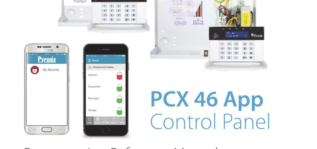
3 2. Introduction 2.1 Hybrid Integrated System with Automation Control The PCX 46 App is hybrid alarm system. It integrates the award winning Enforcer Two Way wireless technology with 30 automation outputs and a host of high security features. The PCX 46 App is easy to use and designed to communicate to you about any system activations via our HomeControl+ smartphone App notification messages. It can also send alarms to the Alarm Receiving Centre and maintenance company. 2.2 Two-Way Wireless Technology Using the wireless input expansion module RIX 32-WE, the PCX 46 App converts into a high security wireless system taking full advantage of Pyronix innovative wireless technology using the Pyronix High Security Wireless Encryption Protocol. This module also allows the access to all Enforcer system 2-way wireless peripherals. Always Alert: The two way wireless movement detectors are fully operational when the system is armed, making your system more secure, compared to other wireless systems, where devices are disabled for up to five minutes after every activation to save battery, therefore compromising your security. Battery Monitoring/Saving: The Enforcer wireless peripherals use advanced technology to preserve the battery life of each wireless device. However, the system informs you when a battery needs replacing a month in advance before the device stops working. This key feature gives you enough time to change the battery in the specific device. Other wireless alarm systems may not give you a low battery warning signal, meaning that devices could stop working, leaving your environment unprotected. High Security Encryption: The wireless protocol is encrypted with 128 bit making it practically impossible to replicate or copy its wireless peripherals. It also uses an intelligent wireless jamming detection technology. User Friendly Keyfobs: Up to 32 wireless keyfobs can be added to the PCX 46 App system. Each wireless keyfob has its own user ID which can be reported to the ARC and user mobile phone. It is possible to allocate different functions to each keyfob such as arming / disarming different areas, activating the automation outputs to control external devices such as gates, requesting system status, and activating panic alarms giving you total control of your system. It shows you the system status using a 3 colour LED: System armed: When the system is armed a RED LED will illuminate momentarily. System disarmed: When the system is disarmed a GREEN LED will illuminate momentarily. System fault: When the system is in fault condition an AMBER LED will illuminate. 2.3 User Automation Outputs The PCX 46 App has ability to operate up to 30 user automation outputs that give you the option activate gates, lights, sprinklers, etc. via your keypad, wireless keyfob or smart phone app. 2.4 SMS Text Alarm Notifications When your system is activated it will notify you via SMS text messages in real time. For example, notification that your child has returned home from school safely or notification of a leakage of water in your property etc. Page: 3


 and no sensitive user data is stored on the")
4 2.5 System Remote Control with the HomeControl+ App The PCX 46 App system can be remotely controlled using the HomeControl+ smartphone App. It allows you to arm and disarm the PCX 46 App, check the system status and bypass inputs. It also allows you to activate remotely up to 30 devices such as gates, lights, sprinklers and more. The Pyronix+ App and Pyronix Cloud communication is fully encrypted to the highest standard (AES 256) and no sensitive user data is stored on the Pyronix Cloud. The Pyronix+ App is available in 2 versions Android from Google Play Store and ios from Apple store. Page: 4
5 3. Keypad Operation Button keys: The following alpha-numerical buttons are used PCX 46 App Programming Reference a = Selects Area A, Upper case /lower case, Exit engineers menu. b = Selects Area B c = Selects Area C, Clears letters / adds a space d = Selects Area D d = Press to Enter Manager Mode f = Press for 2 sec to generate Fire alarm p = Press for 2 sec to generate PA alarm [ = moves cursor left ] = moves cursor right On the PCX 46 App it is possible to write personalized titles for the following: - Inputs, Input Number, Location - Area Names - Site Name - Keypad/Reader, Keypad Number, Location - Input and Output expander location descriptions - User Names The PCX 46 App incorporates a predictive text feature (T9 type). For example, if you enter B Bedroom will be displayed. If the word that you require doesn t appear on the LCD display, just type the word letter by letter. To type a word, press the relevant button the appropriate number of times e.g. for the letter k press the 5 key two times, or for the letter s press the 7 button four times. For punctuation marks, press the 1 button. Page: 5
6 4. The Engineer Menu PCX 46 App Programming Reference The system is programmed from the Engineer Menu. To enter the Engineer Menu, the panel must be fully disarmed state. Whilst in Engineer Mode all tamper alarms (including case tamper), will be disabled. 4.1 Navigating in the Engineers and User Menu x = NO - Press to move forward when in Engineer or Master Manger mode b = BACK - Press to move backward when in Engineer or Master Manger mode t = YES - Press to enter in a submenu or option when in Engineer or Master Manger mode t = Press to move from one option into another option while in a submenu a = Press to quick exit the Engineer Menu from any main menu (written in capital letters) c = CANCEL - Press to move back from one programmable option to the previous option Main Menus and Sub Menus You are in a main menu item if: The maintenance LED is flashing slowly The menu item will be in upper case letters with a question mark (?). You are in a sub menu item if: The maintenance LED is flashing rapidly The menu item will be in lower case letters with a question mark (?). In order to navigate in the menu system one has to answer the questions in the main and sub menus. For example, if the question is LEARN WIRELESS DEVICE. Pressing t will bring you in the sub-menu Learn Inputs? Pressing t will take you to the programmable options of this submenu. Pressing x will take you out of the individual option, will move you up from one submenu to the next sub-menu or back to the main menu. NOTE: For your security, the keypad becomes disabled for 90 seconds after 16 incorrect keypresses, or after 6 attempts to present invalid tags. It will subsequently be disabled again after 7 further incorrect key-presses or after another invalid tag is presented. Once a correct code or tag has been registered, the keypad is returned to normal operation. PIN code entry must be completed within 60 seconds or it will count as an invalid code being used. 4.2 Entering The Engineer Menu (Default Engineer Code = 9999) Access maybe denied if: 1) One or more areas are armed. 2) The Master user has disabled the access of the Engineer Menu from Allow Engineer Menu in the Master Manager Mode. If this is the case Authorization required will be shown on the display. After entering the Engineer code 9999 (default code) the first option that is shown will be: Date & Time?, the fault ( ) LED will flash and high pitch tone will be generated regularly indicating the Engineer Menu has been accessed. 4.3 Exiting The Engineer Menu On completion of programming, the system can be returned back to disarmed mode by pressing the a button from any main menu option (represented in capital letters) or pressing t on the menu option PRESS A TO EXIT & SAVE ENG MENU?. 4.4 Accessing the Engineers Menu on any external wired keypad It is possible to access the Engineer Menu on any keypad that is part of the system. If you are in the Engineer menu in keypad address 0, the other keypads will display system busy. To access the Engineer menu on a different keypad, press the b button on the relevant keypad. 4.5 Saving Your Programming Any programming done in the engineer or user mode will not be saved on the system until the Engineer or User menu have been exited. Page: 6
7 5. Engineer Menu Please refer to the Programming Manual for this chapter. The meaning of every option presented in the Programming manual is explained here in detail. 5.1 Date and Time? All log entries and the system display include the date and time so it is vital that the correct date and time is programmed. This may be also programmed in the Master Manager Mode. NOTE 1: When a modem is connected, the PCX 46 will auto-set the date and time from the network that it is connected to. This will be done: on initial power up, with a mains and battery failure and one hour after the last time update. NOTE 2: Please note that powering down the system and removing the battery will reset the time and date information Time Zone This option is available to help set the correct time for the specified time zone. See APPENDIX A: Time Inputs, page: Change Year For the year 2016, enter Change Month For March, enter Change Day For 31st, enter Change Hours Use 24 hour clock format. For 8pm enter 20: Change Minutes For 7:30, enter Software Clock Adjust If enabled, the control panel will adjust the clock correctly if the control panel gains or loses time. NOTE: This option is used in conjunction with the System Options, Software Clock function Summer Time Adjust If activated this option will automatically change 1 hour ahead and backward for the summer and winter time. 5.2 Learn Wireless Devices? This function should only be used if a PCX-RIX32-WE (Enforcer wireless expander) is connected to the PCX 46 App. Please see the Installation Reference Manual for connecting this expander. This menu learns or deletes wireless devices for the inputs and bells. NOTE: The keyfobs are learned and programmed from the Master Manager menu Learn Inputs? Learn Devices This menu allows you to start the procedure of learning wireless inputs onto the system. Choose Input Use this menu to choose which input on the system you wish to learn. Learnt will be displayed if a device is already learnt, or Available will be displayed if it is not. Choose Input Learning 1) Take the wireless device, and open the casing 2) Remove the plastic insulation between the battery and terminal. 3) If a Device is not learned = The Green and Red LEDs on the Device will flash alternately. 4) Press and hold the learn button on the Device = The 3 LEDs will start cycling. 5) Release the Learn button = Input Learnt will be displayed and confirmation tone on the panel will be emitted. Page: 7
8 6) If an input has already been learnt, Input learnt already will be displayed. Example: The image below shows how to learn an Magnetic Contact. The same procedure is followed for other Inputs and sensors. Please note if smoke or carbon monoxide sensors are learnt, they will just include one multi-colour LED. LEARN >5s Delete Devices Already learnt inputs may be deleted from this menu. Delete All Enter Code To delete all wireless input devices, enter 2000 (this is the PCX 46 App Security Code). Please wait will be displayed while the PCX 46 App deletes ALL the wireless devices learnt on the inputs. Choose Input to Delete This option allows you to delete only a specific wireless device learnt to an input. Any inputs that display learnt can be deleted. Please wait will be displayed while the PCX 46 App deletes the wireless device. Return to this process to delete more devices Learn Bells? Learn Devices Entering this menu allows you to start learning wireless bells onto the system Select Bell Use this menu to choose which bell on the system you wish to learn. Learnt will be displayed if a bell is already learnt, or Available will be displayed if not. Select Bell Learning 1) Open the bell 2) Plug the battery connector into the battery terminal. 3) If a Device is not learned = The Green and Red LEDs on the Device will flash alternately. 4) Press and hold the learn button on the Device = The 3 LEDs start cycling around. 5) Release the Learn button = Bell Learnt will be displayed and confirmation tone on the panel will be emitted. If a Bell has already been learnt, Bell learnt already will be displayed. LEARN >5s Page: 8

9 Delete Devices PCX 46 App Programming Reference Already learnt bells may be deleted by entering this menu. Delete All Enter Code To delete all wireless Bells enter 2000 security code. Please wait will be displayed while the PCX 46 App deletes them. Choose Bell to Delete This option allows you to delete only a specific wireless Bell learnt. Any Bells that display learnt can be deleted. Please wait will be displayed while the PCX 46 App deletes the wireless Bells. Return to this process to delete more devices Learn Wireless Keypads Procedure Learn Devices? Entering this menu allows wireless keypads to be learnt on to the system Select Keypad Select the position to learn the wireless keypad to. If the position is already taken it will display Learnt, if it is free it will display Available. Select Keypad Learning 1) Open the wireless keypad. 2) Plug the battery connector into the battery port. 3) If the device is not learnt = The AMBER and GREEN LEDs on the device will flash (alternating.) 4) Press and hold the LEARN' button on the device and 4 LEDs start cycling through. 5) Release the LEARN button = Wrls Keypad Learnt will be displayed, the GREEN LED on the keypad will flash and a confirmation tone will be emitted from the panel. If the wireless keypad has already been learnt to another position, Wrls Keypad Learnt ALREADY!! will be displayed. Delete Devices Wireless keypads that are already learnt to the system can be deleted from the system by entering this menu Delete All Enter Code To delete all wireless keypads enter 2000 (this is the PCX 46 Security Code). Please wait will be displayed while the PCX 46 deletes them. Choose Wireless Keypad to Delete This option deletes only a specific wireless keypad that is learnt. Any wireless keypads that display learnt can be deleted. Please wait will be displayed while the PCX 46 deletes the wireless keypad. Return to this process to delete more devices Learn Keyfobs Procedure The keyfobs are learnt and deleted from the Master Manager menu. Learn Keyfobs 1) Enter Master Manager Menu (Default Master Code = 1234). Page: 9
10 2) Scroll to the LEARN USER CODES KEYFOBS & TAGS option. 3) Choose a code to allocate the keyfob to. 4) If a keyfob, code or tag are not learnt the space, between brackets will be empty. 5) If a keyfob, code or tag is learnt between the brackets will be shown [******]. 6) Press and hold any of the keyfob buttons for 5sec. 7) A confirmation tone will be emitted and keyfob will be shown on the display. Proceed with the programming of the keys shown next. Delete Keyfobs 1) Enter Master Manager Menu (Default Master Code = 1234). 2) Scroll to LEARN USER CODES KEYFOBS & TAGS option. 3) Choose the keyfob to delete = between the brackets will be shown [******]. 4) Press c. Between the brackets will be shown [ ] to confirm the deletion. 5.3 Program Inputs? By default, all inputs are set to unused. Before programming, identify input type required: #These inputs cannot be bypassed. *Use of inputs 19, 20 and 23 will make the system unable to comply with EN Security Grade 2 or 3. $ Ensure that these inputs are used on an entry/exit route Choose Input Choose an input to program. Input in Area Enter the areas you would like the input to operate in. Common Input In certain situations, a common area may be needed. A common area is an area that only arms if other specific areas are armed. Example: A reception in a building will only need to be armed if the offices and warehouse are armed. If the office is armed, but the warehouse isn t, then the reception would still need to be inactive so people would be able to leave the premises. One input can be allocated to one or more areas. In this example the inputs located in the reception area will be in the offices and warehouse areas and have the common attribute activated. Area A: Office Inputs 1, 2, 3, 4 and 8. Area B: Warehouse Inputs 5, 6, 7 and 8. Input 8: The detector connected to this input is going to be the input located in the Reception and is common to Area A and Area B. Input 8 will only be active if the Area A and Area B are both armed. If one of them is disarmed then input 8 will not be active either Input Attributes? Attribute Chime Allow Bypass Double Knock Combined Input Normally Open Operation for both wired and wireless inputs When enabled the system loudspeaker(s) will chime when an input is triggered whilst the alarm panel is disarmed. Chime can be single sounding once of follow sounding while the door is left open. NOTE: The chime can be turned On or Off in disarmed mode by pressing [c] when all Entry Delay inputs are closed. Enables the input to be manually bypassed during the arming procedure or from the user menu whilst the panel is disarmed. If enabled, an alarm will be generated if this input is triggered twice within the preprogrammed time window or if the input remains active for that period. The double knock option does not work on Follow input type. Alarm will only be generated if 2 inputs one next to the other with Combined Input attribute have been activated at the same time. This option is very useful for setting up out door perimeter protection. Both wired and wireless inputs are normally set to Normally Closed. This attribute allows setting up the input as a Normally Open. Page: 10
11 Mask Test Non Activity Input Special Log (SP) Inertia Input Input Description? PCX 46 App Programming Reference The panel will not arm if the user does not activate each detector with this attribute after starting the arming timer. This is a way to prevent arming the system with masked or faulty detectors. This attribute works in conjunction with the NAT (Non Activity) timer. If a detector has not been activated in during the NAT time the NAT output if programmed will be activated. An event will be registered in the log too. Forces a log entry when the input is opened or closed, even when an alarm does not result. May be selected to apply when a system is armed, when disarmed, or always. If this function is enabled, all inputs will operate as inertia. Please note that only PCX-RIX8i input expanders can be used with this function. Inertia operates by determining the gross attack and pulse count of the force. For example: Gross Attack = 4 m/s. Pulse Count = 3. The input will activate after sensing 3 knocks near the area where the shock is installed (each pulse is kept in memory for 15 seconds). 2 text labels can be associated to each input: Input Location: Here should be written the meaning of the input. There are 14 characters available for this label. Example: Input Number = Input 01; Input Name = Living Room. In case there has been a tamper alarm on an input the SMS alarms will show: input 01, Living Room, Tamper Alarm. On the display will be shown: 01-Living Room, Tamper on Input. Meaning: Tamper alarm on Input 01 that is the Living Room. Enter Number: Best practice is to write the Input Number (Input 01, Input 02 and so on) on this label. This label will be shown in the event log, following alarms, and reported in the SMS alarms as a reference point. There are only 7 characters available for this label. Manually Bypassing Inputs Procedure Method 1: Whilst the system is arming, press the t key to bypass inputs. (EN50131 compliant) Method 2: Enter user menu and from the Bypass inputs option bypass the inputs as required. Automatic Bypassing Inputs Procedure Inputs may be automatically bypassed when the panel auto re-arms if this option is enabled in the system options. 5.4 Program EOL? The end of line programming for all inputs on the PCX 46 can be selected from the below choices and is applied to all wired inputs: Choose EOL Range [0] 1K/1K* (1K Alarm: 1K, Tamper: 1K) [1] 4K7/2K2* (Alarm: 4K7, Tamper: 2K2) [2] 4K7/4K7* (Alarm: 4K7, Tamper: 4K7) [3] 4K7/2K2* Wide (Alarm: 4K7, Tamper: 2K2, Wide means (wide tolerance) that more than one detector can be wired to an input) An asterisk (*) indicates the single end of line value. For example, 4K7/2K2* means the 2K2 is the single end of line value. Please note, when using a RIX8i the 1K/1K can only be used. 5.5 Install RIX? A maximum of 4 x wired input expanders or 1 x wireless input expander can be installed on the Page: 11
12 PCX 46 App. NOTE: Wireless or wired must be chosen accordingly in the menu RIX Address Select the address of the RIX installed (Address 0-3). NOTE: If a PCX-RIX32-WE (Enforcer wireless expander) is installed, each address will enable 8 wireless inputs on the expander. See the Installation Reference for more information RIX Installed Enables the Wired Expander or Wireless RIX that has been installed. 2= Wireless / 1= Wired / 0= No RIX Location The description text is stored for reference on later maintenance visits i.e. GROUND FLOOR. For information on how to use predictive text, please see page Program Outputs? This option enables the programming of the outputs on the Enforcer 32-WE and any devices that are connected. Please see APPENDIX C: Output Types, page: Endstation PGMs? These are the outputs on control panel itself. There are 3 outputs: PGM (relay), Strobe and Bell. This also includes the 9 ATE outputs that are enabled when a loom is connected to the board (please see the Installation Reference manual) RIX Module PGMs? These are the outputs that are located on an input expander module if connected ROX Module PGMs? This option enables the addition of wired ROX modules to the PCX Keypad PGMs? Allows the programming of the PGM options for the output located on the wired keypads Reader PGMs? Allows the programming of the PGM options for the outputs located on the wired readers User Outputs? These outputs are used for creating automation control for Devices. The user can control them remotely from the user menu on the keypad. The automated user outputs can be programmed either latched or pulsed. NOTE: The PGM Outputs polarity cannot be inverted. Only the ATE outputs can. *The use of pulsed or latched keyswitch will make the system unable to comply with EN Install Keypads and Readers? Ensure that all keypads and readers are addressed correctly before enabling them in this function. NOTE: Care should be taken to ensure that every area that can be armed, or to which an Input is allocated, can be disarmed by at least one keypad/tag reader Device Address Address [0] is reserved for the first LCD keypad on the bus. In the addresses from 1 to 5 it is possible to allocate external wired readers or LCD keypads Device Type The device types that are possible to program are LCD keypads [0] or Readers [1] Reader Device Type This option will only appear when you program a Reader into the system. You can then select how you would like the Reader to operate. Arm/Disarm This will make the Reader act like a normal keypad (arming/disarming the areas etc.) Page: 12
13 Device Arms Areas: This feature programs which area(s) the reader can arm. Device Disarms: This feature programs which area(s) the reader can disarm. Device in Area: This feature programs in which area(s) the reader is active. Device Name: Enter the name of the device for example: Front Door. Enter Number: Enter a number of the device, such as: Reader 01 Input Description: Enter a description /any additional information that is helpful. Arm/Disarm Sub-Area A reader can be used to create sub-areas controlled independently from the area. Add inputs: Each sub-area may consist of any number of inputs, all of which must be allocated to the same area. No input may be allocated to more than one sub-area. Entry Delay input types cannot be allocated to a sub-area and in the sub-area the arming/disarming of the inputs is immediate without delay timers. The sub-areas can be operated by proximity tag, or by key (or other) switch wired into the first input on the tag reader. Notice the proximity Tags for sub-area control are programmed through the Manager menu in LEARN USER CODES KEYFOBS & TAGS. The reader provides Alarm and Ready outputs dedicated to that sub-area. It also provides relevant indications, including Arm/Disarm status, so should always be located adjacent to the controlling Key switch where this is used. Sub-Area Arms: If this option is selected as If Area Armed then the sub-area will always arm when the area in which is it located is armed. If selected as Never it will always require manual arming from the tag. The sub-area must ALWAYS be disarmed manually. An additional option is available in the COMMUNICATIONS -> Digi Modem Signalling -> custom Event Type options, called S-Area Alarm-Rst to permit an abort signal to be generated by silencing an alarm at the Reader after an alarm has been generated in the subarea. Action Status Notes Disarmed Detectors within sub-areas Disarmed indication lit are inactive Sub-areas Input triggered No response Attempt to arm sub-areas with an open input - Fault LED flashes and intermittent tone to indicate cannot arm Arming with no open inputs Sub-area arms Disarmed LED distinguishes Sub-area Input triggered Alarm generated Alarm LED lights, alarm tone generated Valid code entered at a Keypad whilst alarm in subarea is active Alarm silenced by user code Sub-area remains armed Sub-Area Control: The sub area can be controlled by Tag or Input. When an input is used to control the sub-area a keyswitch input type should be used and connected to an external key or switch. Sub-Area Name: Enter the name of the sub-area such as Private Office. Enter Number: Enter an appropriate number for the Sub-Area Input Description: Enter an appropriate description e.g. the location of the room /area Assigning Tags to Sub Area Reader: To assign tags to the sub-areas, enter the master manager menu and select LEARN USER CODES KEYFOBS & TAGS, add a new user code (tag) and when the prompt shows Access Reader, enter the address of the reader you would like the tag to operate for the sub-areas. Access Control Allows the reader to control doors fitted with electrical locks. On the readers there are 2 Inputs that can also be outputs. They can be connected to the lock for opening and controlling the door. Lock Open Time: This is the time the door release is going to be active when a valid tag is presented. Door Open Time: This is the time the door is allowed to be open before triggering an alarm. Door Contact No: Give the door contact an appropriate number if required (i.e. if monitoring door) Door Name: Give the door an appropriate name. Enter Number: Enter an appropriate number e.g. a door, reader, keypad or zone number. Input Description: Enter an appropriate description e.g. the location of the door. Page: 13
14 NOTE: Access control falls outside the scope of EN Disarm Only Allows the reader to be used to disarm the system only. Device Disarms: This feature programs which area(s) the reader can disarm. Device in Area: This feature programs in which area(s) the reader is active. Device Name: Enter the name of the door such as Front Door. Enter Number: Enter an appropriate number e.g. a door, reader, keypad or zone number. Input Description: Enter an appropriate description e.g. the location of the door/reader. Entry Control Allows the reader to be used as arm/disarm Device and access control. Device Arms Areas: This feature programs which area(s) the reader can arm. Device Disarms: This feature programs which area(s) the reader can disarm. Device in Area: This feature programs in which area(s) the reader is active. Lock Open Time: This is the time the door release is going to be active when a valid tag is presented. Door Open Time: This is the time the door is allowed to be open before triggering an alarm. Door Contact No: Give the door contact an appropriate number if required (i.e. if monitoring door) Door Name: Give the door an appropriate name. Enter Number: Enter an appropriate number e.g. a door, reader, keypad or zone number. Input Description: Enter an appropriate description e.g. the location of the door. Keypad Device Type Device Arms Areas: This feature programs which area(s) the keypad can arm. Device Disarms: This feature programs which area(s) the keypad can disarm. Device in Area: This feature programs in which area(s) the keypad is active. Device Name: Enter an appropriate name for the device. Enter Number: Enter an appropriate number e.g. keypad 1. Input Description: Enter an appropriate description e.g. the location of the keypad Wireless Keypads There are four positions allocated for wireless arming devices. These appear as Wrls Address 1-4. Device Type This must be set to Wireless Keyp[3] for the device type Options The table below shows the options for the wireless keypad, the choices and what is each choice s consequence Option Choice Function Tag Read Enable Auto Wakeup Supervision Yes [1] (Default) No [0] Yes [1] (Default) No [0] Yes [1] (Default) No [0] This enables the tag reader on the wireless keypad. This disables the tag reader on the wireless keypad. The keypad will automatically wake up during an entry time. The keypad must be woken up manually to disarm the system. The panel will supervise the unit on the system (this is used with the supervision timer.) The unit is unsupervised. If the keypad is taken from site the panel will not notice. Page: 14
15 Back Light Entry/Exit Sound Device Arms Area Yes [1] (Default) No [0] Yes [1] (Default) No [0] [ABCD] When a key is pressed the keypad will illuminate. The keypad will never illuminate. The keypad will mimic the keypad s entry and exit tones. The keypad will be silent during entry and exit times. The areas that the wireless keypad can arm. Device Disarms [ABCD] The areas that the wireless keypad can disarm. Device in Area Device Name? Enter Location [ABCD] Which partitions the wireless keypad is located in. (Any areas the wireless keypad can set but it is not programmed to be in will quick set.) The keypad can be given a name. I.E Factory Extra information on its location can be entered here. I.E North Wall Page: 15
16 5.8 Program Timers? Timers Description Options Entry Time 1 Entry Time 2 Programmes the entry time for each area. If entry time is started at a door programmed in multiple areas, the longest time will apply. Entry time 1 will apply to any inputs programmed as Entry Delay 1 type, and Entry Time 2 will apply to any inputs programmed as Entry Delay 2 type. Ensure that timer is no longer than 45 seconds in order to comply with EN seconds Exit Time Programmes the exit time for each area seconds Bell Time Cut off time for external sounder. Separate for each area. Repeat above steps for each of the PCX 46 areas programmed on your 0 15 minutes system. Bell Delay Delay after burglary alarm before bell activation minutes NOT valid within 3 minutes of final arm, or after entry time started. If Silent 1st Alarm selected in alarm responses, delay commences at confirmed alarm. Strobe Time The duration of time the strobe output remains live after the bell time ends, 99 means endless minutes Number Re arms Number of times system re-arms after bell time ends. Re-arm number applies to each area, and does not affect emergency alarms. 9 = always re-arm. AC Fail Delay Time delay before mains failure or technical alarm signalled. 250 = never alarms. System change-over to battery supply and associated alert indication is always immediate. Mains Fail message on keypad not permitted until valid code entry. Speaker Time speaker and keypad buzzers remain live after bell time ends, Time 99 = endless. Final Door Delay Double Knock Delay Send Entry Line Fault Delay Arm Fail Time Guard Code Delay Fire Bell Time Arm Fail Warning Time between final door input closing and system arming. When a code is entered to arm the system the exit time will start but the system will not arm until it sees the final exit door open and close and duration of the final door delay. Length of filter period applied to inputs with Double Knock input attribute. Delays Burglary alarm signalling if an alarm is generated by deviation from the entry route. Delay Send Entry must be programmed for a minimum of 30 seconds to comply with EN Duration of Telecom (GSM) Line Fault before Line Fault alarm triggered, 250 endless. If a system has not been armed within the entry delay time, for example door left open the Arm Fail Time will take over and at the expiry of this time an alarm will be created. This time should be longer than the Entry Delay time. Minimum time an alarm must have been present before a Guard code will be accepted to disarm minutes 0-99 minutes seconds 0 75 seconds seconds minutes seconds 0-10 minutes Cut off time for fire alarm. 99 = endless minutes The Arm Fail Warning will overwrite the Arm Fail Time feature if 0 99 the Alarm When Arm Fail in System Options has to be set up to minutes NO. Example of how this feature works: Set Arm Fail Warning longer time than the Entry Delay Time. For example if the Entry Delay time is set to 30sec the Arm Fail Time could be set to 1minute. If the system is not armed after 30sec then the Entry Delay Tones will start and the system will be disarmed at the end of the Arm Fail Warning time. An event Arm Fail Warning Activated will be logged in the event log too. Page: 16
17 NAT Day Timer NAT Hours Timer Pulsed Burglar Any WLs Supervision Time WLs Jamming Time Service Time PCX 46 App Programming Reference NAT stands for Non-Activity Timer. This is used in conjunction with the input attribute Non Activity Input, and will monitor the chosen input for the selected number of days. At expiration of timer, and if the input has not opened within that time, then this will be stored in the panel log. Non Activity fault and there will be an output activated if programmed to it. Send SMS message if Special Log is on. NAT stands for Non-Activity Timer. This is used in conjunction with the input attribute Non Activity Input, and will monitor the chosen input for the selected number of hours. At expiration of timer, and if the input has not opened within that time, then this will be stored in the panel log. Non Activity fault and there will be an output activated if programmed to it. Send SMS message if Special Log is on. This option sets up the duration of the pulse of an output programmed as Pulsed Burglary Any activates after a burglary alarm. This is the time window before a supervision fault will be signalled. For example: if the time is set for 2 hours, then any device that doesn t communicate with the PCX 46 within that period will cause a supervision fault. Must be programmed to 2 hours or less for compliance to EN This is the time window that if a wireless device had its signal blocked a fault would display. For example, if the time is set for 30 seconds, then if a wireless device is jammed longer than 30 seconds a fault will be displayed. Must be set to 30 seconds or less (but not zero) for compliance to EN This is a timer that can be programmed in days, and will display a message to the user warning that a service is due. An engineer code will clear the message days hours seconds 0-99 hours seconds Change Codes? All codes may be 4, 5, or 6 digits long and also can be assigned as proximity tags and keyfobs. 100 user codes are available. NOTES: Only Duress/Guard, Master Manager and Engineer codes can be changed by the engineer. User codes can only be changed by the Master Manager from the Master Manager menu. The Master User and Engineer Codes cannot be deleted. User Manager Default: 1234 Engineer Default: 9999 Arm and Disarm System. Also for Access Control and Sub Area Control functions Arm and Disarm System. Also access to Manager menu functions Access to all engineering functions; also arm/disarm system for test purposes. Programmed by Manager only. Programmed by Manager or Engineer. Programmed by Engineer. Duress Disarm system, generating silent Duress signal. Programmed by Engineer. Guard Disarm system, but only after an alarm has been active for a minimum time (programmable). Also arm system. An output type is available to activate whenever this code is used. Programmed by Engineer Change Duress/Guard Codes? Choose Code Number If a code or tag is already allocated, the display will show [******]. Press the key to clear the code. Page: 17
18 Choose Code Number User Type The user type can be Duress [2] or Guard [3] Duress Code PCX 46 App Programming Reference The Duress code can arm or disarm the system and if used a Duress communication event will be sent. An output type is available to activate whenever this code is used (Duress type see page Program Outputs). User In Area Choose the area(s) the code is active in User In Area User Arm Options [0] Disarm/Arm: The code will arm and disarm the areas selected in the previous option. [1] Disarm Only: The code will only disarm the areas selected in the previous option. [2] Arm Only: The code will only arm the areas selected in the previous option. [3] None: No option programmed. User In Area User Arm Options Arm Area Choice If a user code is allocated to more than one area and the Arm Area Choice option is set to NO, the code will automatically arm all areas it has been allocated to in the same time. If the Arm Area Choice has been set to YES then the user will be given the ability to choose which area to arm when the arming procedure has been activated. User In Area User Arm Options Arm Area Choice User Name Write the name of the user of this code Guard Code This code can disarm the system, but only after an alarm has been active for a minimum time programmable in the timers. Use of this code will generate a normal user arm/disarm event. An output type is available to signal whenever this code is used. User In Area Choose the area the code is active in User In Area User Arm Options [0] Disarm/Arm: The code will arm and disarm the areas selected in the previous option. [1] Disarm Only: The code will only disarm the areas selected in the previous option. [2] Arm Only: The code will only arm the areas selected in the previous option. [3] None: No option programmed. User In Area User Arm Options Arm Area Choice If user code is allocated to more than one area and the Arm Area Choice option is set to NO, the code will automatically arm all areas it has been allocated to in the same time. If the Arm Area Choice has been set to YES then the user will be given the ability to choose which area to arm when the arming procedure has been activated. User In Area User Arm Options Arm Area Choice User Name Write the name of the user of this code. NOTE: For both duress and guard codes is possible to program a tag too. If a tag is programmed it has to be associated to a reader Change Master Manager Code If a code or tag is already allocated, the display will show [******]. Press the key to clear the code and use the numeric keys to input the new code. This option allows the engineer to change the Master Manager code should this have been lost or forgotten. User In Area Choose the area the code is active in. Page: 18
19 User In Area User Arm Options PCX 46 App Programming Reference [0] Disarm/Arm: The code will arm and disarm the areas selected in the previous option. [1] Disarm Only: The code will only disarm the areas selected in the previous option. [2] Arm Only: The code will only arm the areas selected in the previous option. [3] None: No option programmed. User In Area User Arm Options Arm Area Choice If user code is allocated to more than one area and the Arm Area Choice option is set to NO, the code will automatically arm all areas it has been allocated to in the same time. If the Arm Area Choice has been set to YES then the user will be given the ability to choose which area to arm when the arming procedure has been activated. User In Area User Arm Options Arm Area Choice User Name Write the name of the user of this code Change Engineer Code If a code or tag is already allocated, the display will show [******]. Press the key to clear the code and use the numeric keys to input the new code Volume Control? The Volume Control function applies to both the buzzer and the internal sounder Area Entry Tone Volume 0=Completely Silent, 1=Silent, but beeps when the system is armed. 2-7 Internal Siren Area Exit Tone Volume 0=Completely Silent, 1=Silent, but beeps when the system is armed. 2-7 Internal Siren Alarm Volume 0=Completely Silent, 1=Silent, but beeps when the system is armed. 2-7 Internal Siren Fire Alarm Volume 0=Completely Silent, 1=Silent, but beeps when the system is armed. 2-7 Internal Siren Technical Alarm Volume 0=Completely Silent, 1=Silent, but beeps when the system is armed. 2-7 Internal Siren Hour Alarm Volume 0=Completely Silent, 1=Silent, but beeps when the system is armed. 2-7 Internal Siren Chime Volume 0=Completely Silent, 1=Silent, but beeps when the system is armed. 2-7 Internal Siren Code Stops Sound This option is very useful when 2 or more independent areas are used on one system. If programmed as Yes, once an alarm has been generated in an area, the user of a different area by his/her user code on his/her keypad will silence the alarm without disarming the area; and an Open After Alarm (Abort) event will be sent for the silenced area. The area will still be armed until a valid user code that controls that area is entered Silent Technical Alert If enabled, any technical alert sounds (such as mains fail, line fail etc.) will be silent. NOTE: If the Exit time has started from an Arm Device programmed in multiple areas, or Entry time started from a door programmed into multiple areas, the HIGHER relevant level will apply Disable Call Fault If enabled, all call faults will not be shown on the display, but they will appear in the log System Options System Options In the system options there are a number of options available to further tailor the operation of the system as to the project needs. The system options are described in the table below: Page: 19
20 Arm With Tamper Arm If Modem Fault Arm With Tec/Flt Arm Fail = Alarm Do Battery Load Test Arm Acknowledge Bypass On Re-Arm Forced Arm Tag Only Disarm Quick Arm Invert ATE PGMs Software Clock Keypad PA Key Manager Program PA ATE Input Tag Disarm+Door Keypad Fire Key Arm with Supervision Fault If Yes, arming will be allowed regardless of the following faults: Case tamper and System tampers. If Yes, arming will be allowed regardless of the following conditions: Telecom line fail, Modem failed, ATE line fault, ATE one path fail, Digi dial fail, ATE communication fail. If Yes, arming will be allowed regardless of whether mains, battery, telecom line, or other system fault is present. If Yes = A graduated alarm will be generated when the Arm Fail timer expires (see Program Timers), if an exit procedure is still incomplete the arm fail output will trigger too. If No = The Exit Time will continue until the Exit door is closed. It will return to disarmed mode at the end of the Arm Fail Warning time if programmed. If Yes the system will perform a full load test of the battery at 7.00am each day. This function is used to indicate the armed status of the system via the bell. Strobe Flash: A single flash will be generated when the system is armed. Bell Squawk: A single squawk for 5 seconds will be generated when the system is armed. Both Strobe/Squawk: A single flash and squawk will be generated when the system is armed. NOTE: This can create a potential security risk. Since the keyfob can show this status too we recommend using the keyfob instead. If Yes, the input that generates an alarm will be bypassed when the bell time expires. If the input is closed then it will automatically become active again. If Yes, the Enforcer 32-WE will arm even if an input is open at the time of arming and will be bypassed (bypass attribute must be enabled). If Yes the Enforcer 32-WE prevents a user code being entered during the Entry Time, but allows a code to silence the Enforcer 32-WE once in alarm. A tag will disarm and reset the system. If Yes, the Enforcer 32-WE allows a user to arm the system by pressing the t key and then selecting the area: A, B, C or D. NOTE: This option should not be used on EN Graded systems. If YES : Positive Removed. If NO : Positive Applied. (Default is YES ). Any output switches from 5 to 0 volts; if set to YES, they switch to 0 to 5 volts If set to YES then the clock will run from the PCX processor, or if NO then the clock will run from the mains frequency. Pressing the dedicated PA button or a combination of 1 and 7 keys will produce a PA. There are several options for this feature: Disabled=Inactive; Silent+Digi=Silent PA (signalling only); Bells Only=Bells Only (No signalling); Bell+Signal=Signalling and Bells. If enabled, a manager will be able to program a wireless keyfob button action as personal attack. Permits selection of inputs on communicator to suit UK STU (including Red Care Reset), ATE Line Fault (including Telback), Do not use or Not Used. Note: This option must be set to ATE or UK STU in order for Line Fault, etc. monitoring to function. This option is NOT required for use with the digi-modem. Used in conjunction with Door Control option in Reader setting. If set to No readers will disarm system but not control doors. If set to Yes the readers control the arming/disarming and doors as long as the reader has been programmed in the reader options. If enabled the fire alarm button on the keypad will be enabled. If Yes the panel will arm the system if there is a wireless supervision fault. The keypad will flag up a wireless supervision fault but allow the user to arm the system. If No will not be possible to arm the system with a supervision fault. The keypad will flag up the fault and the arming procedure will be stopped. Page: 20
21 Keyfob on If Yes allows use of the wireless keyfob to disarm the system only when the Entry Entry Door has been opened and entry time has started. Download if If enabled, downloading from the InSite software to the panel is possible regardless Armed of if the PCX is armed or not. If disabled, downloading will only be possible when the PCX is disarmed. 6 Digit Codes All codes can either be 4,5 or 6 digits. If this option is enabled, all codes must be 6 digits. Time Prompt If Yes the panel will prompt the user to manually update the time if the panel loses the current time. I.E Power cycling the product System Displays Please see page 5 for the Text Programming section as this function involves programming different text for the PCX 46 App system. System Description Displays Area Texts Top Display Text Display If Armed Display Alarms Ready LED ON Display PAs Display Silent PAs Display Inputs Disarm LED ON Exit Options Timed Final Door Push To Arm Timed / Final You may choose how you want each area to be displayed, i.e. Area A may be used to fully arm a house therefore you may want to call it Full House Arm for example. You can have a maximum of 16 characters on the display. The top display text is shown on the keypad in disarmed mode. If programmed as yes then the system will display on the keypads when the system is armed. If programmed as yes then the system will display on the keypads any alarms without requiring user to enter their code or tag. If programmed as enabled, the OK LED will illuminate whilst the panel is disarmed and when all the Inputs in the areas (that the keypad controls) are closed. If programmed as yes then the system will display on the keypads any PA alarms without requiring the user to enter their code or tag. If programmed as yes then the system will display on the keypads any silent PA alarms without requiring the user to enter their code or tag. If programmed as enabled, any inputs activated in disarmed mode will be displayed. If programmed as enabled, the disarm LED (green) will illuminate continuously whilst the system is in the disarmed state. The system will only arm when the programmed 'Exit Time' has expired providing that all inputs are closed. Any 'Push To Arm' buttons fitted will also be live in this mode. The system allows the programming of 2 different Entry/Exit timers to be used with 'Entry Delay 1' and 'Entry Delay 2' input types. The system will only arm when an input programmed as 'Entry Delay 1' or 'Entry delay 2' opens and closes. This procedure is used to allow arming the system by the action of closing the exit door. It is possible to program a small delay time for the final door delay in 'Change Timers'. The system will only arm when a 'Push to Arm' button has been pressed. This function will override the programmed 'Exit Time'. The button can be used as a door bell when the chine input attribute is enabled ('Program Inputs') This function follows the 'timed' operation, except that the timer will be overridden if an Entry Delay input (door) is opened and closed before the timer expires NOTE 1: If the arming has not been completed within the programmed 'Entry Delay' time, it is possible to generate an alarm or return in disarmed mode. This option is defined in 'Change Timers' and 'System Options'->Options' Review Logs? There are two logs available on the system, panel and access control. Each log displays most recent event first. Use the [] keys to move forwards and backwards through the log. To view additional details, press the c key. If no other information is available, the display will move to the next log Page: 21
22 entry. Pressing the a key will return to the main screen for that entry. NOTE: In any disarmed or armed period, the PCX 46 App will only log a maximum of three occurrences of any particular event. It is not permitted to delete logs The Panel Log? Includes Arm, Disarm, Trouble, User, Alarm, Engineer Access, Time & Date changes and etc The Access/Control Log? Includes all Access Control and Guard Tour events Engineer Tests? This function allows the engineer to test inputs, outputs, batteries and the bell Walk Test? This function allows the engineer to test all programmed inputs on each area. The Inputs that haven t been activated will be shown on the display. As each Input is triggered, a chime will sound and that input will disappear from the scrolling list. Once all the Inputs have been walk tested, Walk Test Completed will be displayed. When walk-testing a double-knock detector, it must be triggered twice within the preset period. When testing combined detectors, you must first activate the first detector once and then trigger the second detector; next open the second detector and trigger the first detector. A walk test can also be done on a single input if needed. This can be selected by pressing the x key after the areas are displayed. NOTE: The walk test feature can only be used if inputs are already programmed and saved (i.e. after exiting the Engineers menu) Soak Test? The Soak Test is used when inputs need testing without creating problems for the user. For example testing a perimeter alarm set up when false alarms are likely. If the input in soak test is activated whilst the area(s) in which it is located is armed, it will indicate the activation (at disarm) and enter the details in the system log. NOTE: If additional inputs are placed on test without removing previously tested ones, they will be returned to soak test Bell Test? Any outputs programmed as any bell or any strobe (including the wireless bells) will be activated in this test Battery Load Test? The system performs a check of the battery operation every 10 seconds, by dipping the power supply voltage momentarily, and measuring the system voltage. If the battery voltage measured is below 12.0V, or the battery fuse has failed, a BATTERY FAULT 100 warning will be generated. The PCX 46 App may be programmed to perform an automatic battery load test at every power supply at 07:00am each day from SYSTEM CONFIGURATION? -> Options -> Do Battery Load Test (See page 19) menu. This will drop the power supply voltage below the battery voltage, whilst monitoring the system diagnostics. The test will NOT take place if: the End Station bell and strobe PGMs are active, the system is in Engineer Mode, any battery fault exists, any mains fault exists, or the system option is not selected. If the test has already started, it will be aborted if any of these conditions apply, other than entry into Engineer Mode. If the test is aborted, it will NOT take place until the next day Test PGMs? Before you can test any outputs, the output programming must be saved to the NVM by first exiting the Engineer Menu. The engineer can test all the Programmable Outputs on the End Station (panel), ROXs, keypads and readers Send a Test Call? If Contact ID or SIA has been programmed, you can send a test call from this option. The system will send a test call event once the call is activated. Press the t key after the prompt Are you Sure? By-pass Fire/PA? Whilst in the Engineer menu, the Fire and Personal Attack inputs/keypad alarms remain active. This function disables any Fire/PA activations when the Engineer menu is active. Page: 22
23 5.14 Diagnostics? This option enables the engineer to perform full diagnostics on all key wired and wireless components of the system Wireless Devices? View Inputs? This option shows the status of the wireless inputs such as Open, Close, Tamper, Fault. If the t key is pressed after the input status, a resistance reading will also be shown. View Inputs Signal Strength? This option is used to measure the signal strength for wireless inputs. The signal strength is shown on each individual wireless Device as well as on the control panel. On each Device a Green LED will show good or excellent and Red LED will show weak or no wireless signal. View Bells Signal Strength? This option is used to measure the signal strength of wireless bells. View Wireless Keypad Signal Strength? This option is used to display the signal strength of the wireless keypads. On each device the green LED will flash for good or excellent signal strength and the red LED will flash for low signal strength. View Inputs Battery Status? This option is used to check the wireless devices battery status information if a PCX-RIX32-WE (Wireless expander) is connected to the panel. View Bells Battery Status? This option is used to check the bells battery status information. View Wireless Keypad Battery Status? This option is used to check the battery status of the wireless keypads Wireless Dual Frequency Menu NOTE: The PCX 46 must have a PCX-RIX32-WE that is version >3.5 installed for this menu to be visible. The wireless expander is capable of switching frequency if the primary frequency gets jammed or is in a noisy environment. All wireless devices on the system must be version >3.5 in order for the expander to switch frequency. Channel This option will display the frequency channel that the expander is operating on. 01 Primary frequency 02 Secondary frequency Channel Reason This option displays the reason that the expander has had to switch frequency SF/DF Status This will display whether the panel is in single frequency or dual frequency mode. If this displays single frequency there will be devices on the system that are version <3.5 First SF Device This will display the first single frequency device on the system. As the device displayed is deleted, it will display the next single frequency device until all remaining devices are dual frequency Wired Devices? View Inputs? This option shows the status of the wired Inputs such as Open, Close, Tamper, Fault. If the t key is pressed after the Input status, a resistance reading will also be shown. This menus is subdivided into Panel zones, Expander zones, Keypad zones, and reader zones for ease of use. View PSUs? Panel PSU: End station voltage readings are displayed = Voltage: 13.7V. Exp PSU (expander): Choose the expander address from [0] to [3] to read the PSUs voltage readings. O/P Mod PSU: Choose the output module address from [0] to [2] to read the PSUs voltage readings. Keypad Volts: Choose the Keypad address from [0] to [5] to read the keypad voltage. Page: 23
24 Reader Volts: Choose the Reader address from [0] to [5] to read the reader voltage. Calibration? For manufacturer use only unless otherwise instructed Communications Diagnostics? Signal Strength? This function shows the GSM/GPRS signal strength (15-30 Good, below 15 Low) and the network as well as the GPRS modem version (if a Digi-GPRS with a valid SIM card is connected to the panel). APN Status This function shows the APN data/server connection status (initializing/no network/basic network/full network/polling Cloud) Please see the programming manual for further information on each status. ARC Status This function shows the ARC connection status (initializing/no network/basic network/full network/polling ARC) Please see the programming manual for further information on each status. Last Polled App This function displays the time and date that the system last made contact with the HomeControl+ App. Last Polled Cloud This function displays the time and date that the system last made contact with the PyronixCloud. Last Polled ARC This function displays the time and date that the system last made contact with the ARC (Alarm Receiving Centre). PSTN Line Status: Displays the Line status of the PSTN telephone line connection (if a Digi-1200 PSTN module is installed) Engineer Restore Options The Engineer Reset Options are used so that once an alarm has occurred; the PCX control panel system can only be reset by an Engineer code, anti-code or red care reset from an Alarm Receiving Center (ARC) Restore Burglary If 'UK Intruder', an Engineer code must be used to reset the PCX control panel after an alarm. 'Secure Intruder' should not be used Restore PA If 'YES', an Engineer code must be used to reset the PCX control panel after an Hold Up, Input Hold Up, or Duress activation Restore Tamper If 'YES', an Engineer code must be used to reset the PCX control panel after a tamper activation Restore Soak If 'YES', an Engineer code must be used to reset the PCX control panel after an input that is on 'soak' has triggered when the PCX control panel is set Restore Faults If 'YES', an Engineer code must be used to reset the PCX control panel after the following faults: ATE telecom fail, Modem fail, ATE single path fail, Telecom line fail, Battery disconnect, Batt charge, Battery load, Excessive charge, Battery critical and Device fail Anti-Code Restore If 'YES', the PCX control panel will display an Anti-Code, to which can be used to generate a special reset code (usually from the ARC) to reset the PCX control panel. NOTE: that if Anti-Code is selected, this will coincide with the options that have been selected previously. For example, if Engineer Restore Intruder is selected, and Anti-Code is selected, then an anti-code will be produced on intruder activation. Page: 24
25 5.16 Communications? The Communications function programs the App, network, ARC, SMS and UDL facilities Set Up App? The HomeControl+ App is available in two versions: Android from the Google Play Store; and ios from the Apple store. Please refer to the App Setup Guide and user guides for more details. Use App: Enables the app functionality. System ID: Displays the unique System ID used to register the PCX 46 App with the PyronixCloud. Cloud Password: A password is required to allow cloud access. Security: Normal: Requires only a password for connection. High: creates the following menu options; o Generate App Password Key: A 24 character Hex-key is generated. o View App Password Key: Displays the key that has previously been generated. o Send Password Key in an SMS (when a GPRS module is fitted): Once a mobile number is entered, an SMS is sent with the security key. App Password: The password that is entered on the App itself Poll Server (Cloud): Yes: The PCX 46 App Panel will poll with the PyronixCloud App server regularly. No: The PCX 46 App Panel will not poll with the PyronixCloud App server. An SMS being sent to the panel may be required to initiate communication. The timing of the poll is 8 minutes Network Set-Up? Three different modules can be connected to the PCX 46 App Panel to enable different forms of communication. Please refer to the Installation Reference manual for information. The sub-menus will be enabled only for the module installed. Program GPRS? GPRS APN: Enter the GPRS APN, such as orange internet. GPRS User ID: Enter the GPRS user ID if the network requires this. GPRS Password: Enter the GPRS password if the network requires this. Program LAN? Enable Auto IP? Yes: The PCX 46 App Panel will obtain the set up data from the router using DHCP. No: The following will be required: o IP Address: Enter the IP Address where xxx is a number between 1 & 255. o Subnet Mask: For most domestic installations the subnet mask will be o Router Address: Enter the gateway, i.e. the routing device that the panel is connected to. o 1 st DNS IP Address: Enter the DNS Server IP Address. o 2 nd DNS IP Address: Enter the alternative DNS server IP address if required. Program Wi-Fi For future use Digi Modem signalling? The PCX 46 App system can communicate with an Alarm Receiving Centre (ARC) using the LAN module, PSTN or the GPRS modem. ARC Details: Choose which ARC to program from 1 to 4. Modem Type Used: PSTN GSM GPRS GSM / GPRS VOICE PSTN (future use) WiFi (future use) Ethernet (LAN) Formats Available: Contact ID/Contact ID IP = See page: 44 for the event table. Page: 25
26 SIA IP, SIA levels 1 & 3 = See page: 44 for the event table. Valid Areas: This option permits the set up of a different ARC for a different area. Select which area this particular ARC will be reporting. Selecting ABCD0123 means the ARC will be receiving events from all areas. Area Accounts One Area Account This options permits the engineer to set up an individual area account for each area or open common account for all of them. Use the a key to add hexadecimal values; B to F. Numbers are entered by the number keys. Redials: If the alarm event has not been received by the monitoring station after the first number has been called, the second number will be called. The two numbers will be alternated as many times as the redials are set to. If a call has been acknowledged by the monitoring station then PCX 46 App Panel will stop calling. Time-out: This is the time in seconds before a call times out from not being answered/received. Test Calls: The test call is used to show that the system is still active when no activations have been made. Setting up a test call asks for a start time in hours and minutes and the frequency of the call in days, hours and minutes. Event Types: Please see page: 44 for all event options. If Custom is selected, all event types can be chosen. Sign Up ARC: ARC Sign-Up IP: The ENIP Address that is supplied by the ARC. ARC Sign-Up Port: The Port of the ENIP Server that is supplied by the ARC. Security: Normal: Requires a password and connection handle (supplied by the ARC). High: Send Key by SMS: o Yes: The security key will be sent by the ARC software to the panel. o No: The security key and connection handle must be entered manually on the panel. Send Sign Up to ARC? o Sign Up Successful: A message will be displayed indicating that the sign up was successful. o Sign Up Failed: This may be due to the following reasons: Incorrect Security Key Incorrect Connection Handle ARC Server not available Account already exists SMS Signalling To signal via SMS, a valid mobile number and the desired event types must be programmed. SMS Details: Up to 10 mobile numbers can be programmed. User Mobile: The mobile phone where all events will be sent can be entered with or without the international dialling code (use the a key to enter the + symbol). The international dialling code must be entered if the number is from a foreign SIM card. Valid Areas: This option permits the set up of a different ARC for a different area. Select which area this particular ARC will be reporting. Selecting ABCD0123 means the ARC will be receiving events from all areas. Redials: If the alarm event has not been received by the monitoring station after the first number has been called, the second number will be called. The two numbers will be alternated as many times as the redials are set to. If a call has been acknowledged by the monitoring station then the panel will stop calling. Timeout: This is the time in seconds before a call times out from not being answered/received. Test Calls: The test call is used to show that the system is still alive when no activations have been made. Setting up a test call asks for a start time in hours and minutes and the frequency of the call in days, hours and minutes. Event Types: Please see page: 44 for all event options. If Custom is selected, all event types can Page: 26
27 be chosen. SMS Common Message: This message will always be sent as part of the SMS activation text Advanced Communications Prefix Tel No: This option only appears if a PSTN (Digi-1200) modem is installed. It allows you to enter a number or series of numbers that will prefix all outgoing calls. For example, a lot of telephone systems require a 9 adding to the beginning of a number so that an external call can be made from an internal extension system. Wait Dial Tone: Allows a dial tone to be transmitted or not for compatibility with different telecommunications equipment (This option only appears if a PSTN (Digi-1200) modem is installed). Send Events UDL: This option enables or disables the sending of system events via the Insite UDL software. Modem Tel no: One telephone number can be entered for each of the UDL PCs associated with your alarm system. Send Alarms/Faults/Open/Close/Access Ctrl: - The following menus allow you to enable or disable the event categories/types that are sent via UDL Alarm Responses? The Alarm Response function controls how the system communicates when certain alarms are active. The different alarm responses are: Keypads, Internal Sounders, Bells Only and Signal Digi (communication to ARC or user). The different alarm responses work on a cycle (starting from Keypads and finishing at Digi ). Each alarm response stage will take 15 seconds before moving on to the next response. For example, If the alarm response for Area A starts at Internal Sounders and stops at Digi, then once Area A is armed and an alarm has been activated, the internal sounders will first activate, then after 15 seconds the Sirens will activate and then after another 15 seconds the Digi Modem will activate (signal). The Enforcer 32-WE can operate on a combined area basis, for example if both areas A and B are armed; it may be desired to have the process of the alarm responses to change. Therefore, the If areas armed section would be used, the desired areas and the alarm responses selected. If A, B, C is entered for example, then A, B & C must be armed for the upgrade to take place. This option is a very useful when an outdoor perimeter area is created. It allows the creation of audible and communication alarms following different rules compared to other areas in the system Area A, B, C, D Starts at: This feature programs where the Alarms for each area A, B, C or D start: Keypads, Internal Sounders, Bells Only or Signal Digi. If programmed as keypads then the alarm will start from keypad sounders and then depending on where it s programmed to stop at -will progress up to a maximum of communicating the alarm event i.e. Digi. Each alarm response will take 15 seconds before moving on to the next Area A, B, C, D Stops at: Alarms for each area can stop at: Keypads, Internal Sounders, Bells Only and Signal Digi. For example, if programmed to start at keypad and stop at keypad this means the alarm will only be ever displayed on the keypad Fire Alarm Starts at: This feature programs the starting point of alarm responses for fire alarm. The levels are: Keypads, Internal Sounders, Bells Only and Signal Digi Fire Alarm Stops at: This feature programs the ending point of alarm responses for fire alarm: Keypads, Internal Sounders, Bells Only and Signal Digi Gas Alarm Starts at: This feature programs the starting point of alarm responses for Gas alarm. The levels are: Keypads, Internal Sounders, Bells Only and Signal Digi Gas Alarm Stops at: This feature programs the ending point of alarm responses for Gas alarm: Keypads, Internal Page: 27
28 Sounders, Bells Only and Signal Digi PA Alarm Starts at: PCX 46 App Programming Reference This feature programs the starting point of alarm responses for PA alarm. The levels are: Keypads, Internal Sounders, Bells Only and Signal Digi PA Alarm Stops at: This feature programs the ending point of alarm responses for PA alarm: Keypads, Internal Sounders, Bells Only and Signal Digi Hour Alarm Starts at: This feature programs the starting point of alarm responses for 24h alarm. The levels are: Keypads, Internal Sounders, Bells Only and Signal Digi Hour Alarm Stops at: This feature programs the ending point of alarm responses for 24h alarm: Keypads, Internal Sounders, Bells Only and Signal Digi Any Alarm Starts at: This feature overrides the settings above. It can be used to create greater flexibility in the use of the alarm responses feature and in this case it s set up for each area if they are in armed status only If Areas Armed Select the areas that the following settings will be applicable to Any Alarm Stops at: For example, if 24 Hour Alarm is set to Start at Keypad and stops at Keypad, this feature allows set up for all Areas if they are armed to make any alarm stopping at Digi If Areas Armed Select the areas that the above setting will be applicable to Options Up/Downloading? The system can be programmed from the keypad or the InSite UDL Software. There are 2 methods of connection for programming the panel via the UDL Software: 1) Via the RS232 input locally; 2) Remotely GPRS, PSTN or LAN modems. The UDL InSite Software allows the servicing and monitoring of the system and review of the logs. RM Service: The Remote Maintenance Service is an automatic service performed by the panel and the InSite UDL Software. This service enables the panel to automatically call a PC with the InSite UDL software installed and deliver all diagnostics data to that PC. In this way the installer does not have to visit the site to measure all the required measurements. This information could be used for creation of regular technical reports to send to users as a proof for maintenance of the site. Technical Alarms Monitoring It is possible to program the panel to call the UDL InSite Software when alarms, faults, arm/disarm and access control events are generated to up to 4 PCs running the UDL InSite Software RS232, Local Connection The RS232 is used to program the panel locally connecting it to a PC running the UDL Software via a special cable. If this option is chosen no other programming is required Modem, Remote Connection The modem (PSTN/GPRS/LAN) is used to program the panel remotely connecting it to a PC running the UDL Software via data modem. Dial Mode Option (when modem selected) This function programs the procedure used for the call between PC and panel: Auto Answer: When called from a PC the panel will answer the call immediately. Dial Back: When called from PC the panel will take the line, disconnect and call the PC. Panel Dials: Does not allow the PC to dial into the panel. A call has to be initiated by the user or engineer from the panel. Dial In Options Page: 28
29 Direct Dial: When the PC dials the panel, it will respond immediately. 2call Ansr (Shared Line): When the PC dials the panel, it will hang up after a designated number of rings, and dial again. The first call primes the panel, which will then answer the second call. The number of rings to prime the panel is entered in Number of Rings before AMC menu option. Number of Rings for 2call: Enter the number of rings needed to prime the panel before answering the next call. Modem Speed This option defaults to high but may be set to medium for compatibility purposes. Prefix Telephone Number The prefix is an extra digit required to reach the panel i.e. dial 9 to get an outside line. Redials: The number of redials that it will call to the InSite software before it fails. UDL Password This password is used to identify the UDL connection. Make sure the password here and on the PC InSite software are the same. Site Name: Entry of a Site name is optional however if it is entered, ensure that it is the same (verbatim) here and on the Insite software. UDL Priority: We recommend that this is set to High if set to normal then HomeControl+ App notifications may disconnect the UDL connection while you are trying to use UDL Cloud, Remote Connection The GPRS modem is used to program the panel remotely connecting it to a PC running the UDL Software via data modem. In this function the System ID will be displayed, and a UDL password key can be generated in order to connect. UDL Password This password is used to identify the UDL connection. Make sure the password here and on the PC InSite software are the same. Site Name: Entry of a Site name is optional however if it is entered, ensure that it is the same (verbatim) here and on the Insite software. UDL Priority: We recommend that this is set to High if set to normal then HomeControl+ App notifications may disconnect the UDL connection while you are trying to use UDL Software Revision? This option shows the software version, hub version and modem version installed in the panel. Please obtain the software version number prior to contacting customer support so that the correct information can be given upon supporting the product Factory Default? This option is used to reset the panel to a factory default Factory Default Code The Default code is: 2000 Once applied the system will be reset to factory defaults Clear Wireless Data? This option will give the installer the option not to clear wireless devices if they have been programmed on the system already Clear Codes? This option will give the installer the option not to clear user codes if they have been programmed Page: 29
30 on the system already Exit Engineer Menu? Either exit via the EXIT ENGINEER MENU option or press a from any other main menu. 6. Adding External Wired Keypads The keypads have a small internal menu used mostly for addressing, changing key click volume and brightness of the LCD display Entering and Exiting the Keypad Menu To enter the keypad menu, press and hold the d button until SECURITY CODE: is displayed, and then enter To exit, press the a key Keypad Menu Options ADDRESS = Used to assign an address to a keypad [00] is the keypad on the panel LANGUAGE = Allows to assign a language used only for the keypad menu only KEYPAD INPUTS READING = Showing the resistor reading and status on the 2 inputs located on the keypad KEY-CLICK VOLUME = Sets the volume of the buttons TAG VOLUME = Sets the volume when tag used KEYPAD VOLUME = Sets the general volume of the keypad ID TAG = Used to read the ID unique number of the Tag RESET KEYPAD = Resets keypad to factory BACKLIGHT = Sets the backlight intensity of the keypad DELAY FIRE AND PA BUTTONS = Sets the how long the PA and Fire buttons have to be pressed for before an alarm is created Testing The Keypad With the system disarmed, press and hold the b key for 10 seconds at any keypad. This will cause all the LEDs on that keypad to illuminate and the LCD screen to scroll a display testing each pixel. The keypad will revert to normal display approximately 10 seconds after the b key is released. Page: 30

31 7. Options Programmable Only From PC The UDL software is available on The software can be used to upload/download to the control panel and data can be viewed. Two features that the UDL software incorporates are describe below: Auto Arm & Disarm Timer Logic Gates Please refer to the UDL software help guides for help in the initial software set up first. 7.1 Auto Arm/Disarm Timers This function will allow automatic arming and disarming procedures. This is useful when a premises is left unmanned for a period of time (due to holidays etc). Create a new customer, and select 'PCX 46'. The Auto-Arm/Logic Gates will be enabled, click the button. Adding Arm/Disarm actions 1. Select 'Add Action'. 2. Select the Day of the week that requires to be 'Auto Armed'. This will then be displayed in the list. 3. Select the action of this timer (E.g. Arm) 4. Select the time (24 hour: E.g. 14:00) when the action should start. 5. Another action can now be added (E.g. Disarm) and select the time for this action. Adding 'Holidays' A holiday setting will override any auto timers that coincide with the holiday. Once the holiday has passed, it will not repeat the year after or at any other time. 1. Click 'Add Holiday' 2. Select the dates that are required for the holiday period. These will be displayed at the top right of the screen under 'Date.' 3. If any holidays are added by mistake, select that holiday and click 'delete'. NOTE: Make sure that any action already programmed matches correctly when the holiday period has finished. E.g. If the dates January 1st, January 2nd, and January 3rd are selected, the panel will stay armed on Page: 31

32 all dates regardless of the auto timers. However, an auto timer should be set up to disarm the day after the holiday has ended if required. 7.2 Areas to Arm/Disarm This section of the software selects the area's that will be Armed/Disarmed during the 'Auto Arm/Disarm' period. 1. Select the areas to be armed and type them in the 'Area's' field. 2. Select the 'Warning Period'. This is a time (in minutes) when the control panel will warn anyone who may be in the premises that an auto arm is about to take place. NOTE: The warning time is additional to the Auto-arm time. E.g. if the auto arm time is 22:00, a warning time of 15 minutes will added to this, so the actual panel arm time will become 22:15. If the panel must arm at 22:00, but a 15 minute warning time is also needed, the auto arm time should be selected as 21: Select the 'Delay to Arm' time. This time is used if a person in the premises needs to delay the auto-timer. If a code is entered on the control panel during the warning period time, the auto timer can be delayed. E.g. If the warning period is set to 15 minutes, and the Delay Auto-Arm Time is set to 20 minutes. Then a user will have a further 5 minutes before the Auto-Arm begins. NOTE: It you do need a delay auto arm time, it is recommended that this time is set to 1 minute more than the Warning period. The delay auto timer must always be set higher than the Warning Period. 4. Select the areas to disarm for the Auto-Disarms programmed previously. These are usually the same as the areas that have been selected to Arm. 5. The '12 month calendar' is for using repetitive holidays that need to be repeated every year. For example this may be needed for national events, memorial days, birthdays etc. Once all completed, exit the screen by clicking 'OK' and download the data to the control panel. 7.3 Programming Logic Gates Logic Gates allow the use of logical operations (OR, AND and NOT) to give greater control of how an output is activated. Rather than having an output activated following a burglary alarm, it is possible to create an output that is activated, for example, when there is a burglary in area A AND when area C is also armed. This could be useful in a scenario where different offices are occupied in different areas, and you do not want an external communicator or siren to signal an alarm in one area if other areas are still occupied. 5 logic gates are available for programming. To program logic gates: 1. Select the Logic Gates tab 2. Select the gate type: AND, OR, NOT 3. Select the inputs (up to 4 can be selected). These are the input types of the control panel. 4. Up to 5 logic gates can be programmed (Gates 16-20). These can only be programmed in the UDL software under 'Inputs/Outputs' button. NOTE 1: Each gate can only be programmed with one logical operator. For example, a gate can be programmed as A OR B OR C, but not A OR B AND C. If you wish to combine different logical operators you will need to split the operation between two logic gates. Thus to obtain A OR B AND C you can use the flowing logic: Logic Gate 1 = A OR B; Logic Gate 2 = Logic Gate 1 AND C. The following example shows how you would program the command: {[ Burglary Any OR Tamper Any ] AND Ready C }: NOTE 2: Only Gates can be programmed. Gates 1-15 are for future use Page: 32
33 8. Faults and Troubleshooting 8.1 Device Fail / Active Faults If a device on the PCX 46 App system is not installed correctly or has been lost from the bus, a device fail will be present. An example of each fault is as follows: - Failure on the panel = Control Panel, Battery Fault - Keypad address 3 (0-5 available) failure = Device 3, Device Fail Kpd - Internal/External Tag Readers address 2 (1-5 available) failure = Device 2, Device Fail Trd - Remote Input Expander address 0 (0-3 available) = ZEM-00, Device Fail ZEM - Remote Output Expanders address 0 (0-1 available) = ROX-00, Device Fail ROX If a location name is entered for a device, the location will be displayed on the keypad instead of the address, for example instead of Device 3 for the Keypad, it would display Entrance Corridor. 8.2 System Faults and Troubleshooting Communications Faults Fault Description Solution MODEM FAULT The panel is unable to see the Digi Modem If modem not present, ensure that Disable Digi option is set to YES and DOWNLOAD MODE is set to NONE or RS232. If present, but not detected, check Digi Modem cable is connected correctly. LINE FAULT CALL FAIL TO ARC DIGI LINE FAULT DIGI Call Fail 100 There is no telephone or GPRS/GSM line Call to ARC has failed. NOTE This is a communication problem, which is rarely caused by an equipment fault. Most likely related to hand shake and kiss off frequency set up at receiver. PSTN Line Fault signalled by device using DIGI/ATE pins on the panel. Call to ARC from device using End Station DIGI/ATE pins has failed. Page: 33 Make sure to plug the PSTN modem in analogue convention type telephone line. Make sure the SIM card is plugged on the modem Make sure the GSM/GPRS signal is good enough. Check ALL call details are programmed correctly. Ensure signaling format is correctly set for ARC receiver. Check voltage on input pin if +5/12 volts, device connected is showing fault. Note: 'Line Fault' timer operative Check voltage on input if +5/12 volts, device connected is showing fault
34 8.2.2 RS485 Bus Problems PCX 46 App Programming Reference Fault Description Solution DEVICE FAIL xxx xxx = ROX xxx = ZEM xxx = Kpd xxx = Trd xxx = Pnl Wired Device on the RS485 bus has been lost. Each Device is recognised by its own name such as: Output expander = ROX input expander= ZEM Keypad = Kpd Reader = Trd Control panel = Pnl Identify device. Check device addressed correctly to match programming. Check connections at device, and cabling to it. If above correct, re-boot device, followed by reboot of End Station. 485/COMMS LOST Keypad display is BLANK KEYS LOCKED OUT Detection Faults Displayed on keypad that has not yet established communications with the control panel (End Station) Keypad address does not match any keypad enabled in the panel. a) More than one device connected at the same address. b) Too many incorrect key presses have been entered to create Code Guessing condition. Page: 34 Part of routine initialisation procedure. If persists, check display at other keypad(s) to confirm if device failure is at keypad or complete system BUS failure. Temporarily install additional keypad. Check keypad address by pressing and holding [D] until the security code is required. Enter 2000 and set the keypad address. The primary keypad address MUST be always set to [00]. Make sure in the Install Keypads and Readers menu in Engineer mode that the keypad address set up correctly. a) Correct addressing so that no overlaps. Then power system down and up again to correctly reinitialise. b) Wait 90 seconds for keypad to be reintroduced onto the system. Fault Description Solution BELL TAMPER Tamper fault detected on connection from SAB Terminal TR should be at or near 0v. If not, is Bell Tamper switch closed? Check Fuse F2 intact, and connections to SAB. CASE TAMPER Case tamper switch open Ensure the switch is closed Code Guessing Up to 13 Invalid key presses have been entered or 3 invalid tags have been presented. Press the X key to clear. BELL Fault Power Supply Problems Bell or other warning device has triggered its fault output which is detected by the control panel Correct fault at warning device to restore the output. Fault Description Solution BATTERY FAULT xxx Battery not present or Battery volts low Note: This indication should be expected during recharge after a mains failure. BAT LOAD FAIL Battery Load Test has failed Only displays if option selected. Battery uncharged or capacity below specification may need replacing. BAT CRITICAL Battery being disconnected Protects battery from deep discharge damage during extended mains failure. Note: System is about to be powered down! MAINS FAIL xxx Mains supply failed System detects mains frequency out of specification, as well as voltage. Note: AC FAIL timer operative FUSE x FAULT Fuse identified failed, OR Output protected by fuse Fuse 1 = O/Ps, Fuse 2 = BELL Fuse 3 = AUX, Fuse 4= BUS
35 drawing excessive current Fuse 5 = BATTERY LOW VOLTS xxx Power supply volts low Battery volts below normal battery fault level during mains failure Engineer Indications Fault Description Solution Engineer Access Denied Access to Engineer menu NOT possible, as system is not fully disarmed. Ensure that ALL areas are disarmed, using a suitable user codes / tags at appropriate keypads / readers. Check Failed Input xxx Error Input Areas not accessible Error some Areas cannot be disarmed Wireless Faults Input in fault on attempting to exit Engineer mode. A Input has been programmed to an area for which no arming point is valid to disarm. Arming points have been programmed so it s possible to arm an area, but not disarm it. Page: 35 Applies to 24-hour tamper, or other Input types that would generate an alarm condition if the system were returned to disarmed mode. Also applies to tamper fault on other Input types. Check for fault on Input, or omit in programming. It would therefore be impossible to fully disarm the system after a tamper alarm on that Input. Programming must be adjusted before exiting Engineer mode. Programming must be adjusted before exiting Engineer mode. These faults will only be possible if you have a wireless expansion module installed. Fault Description Solution U-01 (xx) WLs LOW BATT Low battery on wireless keyfob (user) number xx Replace the battery on the mentioned keyfob I-01 (xx) WLs LOW BATT Low battery on wireless Input number xx Replace the battery on the mentioned Input device B-01 (xx) WLs LOW BATT Low battery on wireless bell number xx Replace the battery on the mentioned radio bell I-01 (xx) WLs SUPERVN Device on wireless Input number xx has not checked in Walk test the detector, perform a diagnostic signal strength test and try replacing the battery B-01 (xx) WLs SUPERVN - 01 (xx) CASE TAMPER Wireless bell number xx has not checked in within time of 20 min Tamper fault on input number 01 xx = any input number Test the bell, perform wireless signal strength diagnostic. Consider replacing the battery or relocating the bell. Check the tamper switch on the detector and make sure the case is closed properly. Check the tamper switch on the mentioned radio bell WLs TAMPER Bxx Tamper fault on wireless bell number xx WLs JAMMING Jamming fault on the panel. Check no radio interference is in close
36 Pnl WLs Supervn Fault WLs Input / Input Type Mismatch Something is jamming/interfering with wireless peripherals. No supervision polls were received for 20 minutes before the arming operation. Wireless Input or Bell input number will be shown so the problem is easily identified. Wireless devices are learned on Inputs but no zone types have been programmed for them. proximity to the radio devices/panel. Test the signal strength / battery on each wireless device Program input type for each wireless device learned in the PROGRAM INPUTS Errors When Arming Fault Description Solution Please leave via If the exit mode is programmed Leave via the agreed exit route. exit door as Final Door, then you must leave through that door to arm the system. Exit Via If any follow detectors or door contacts are open during the arming procedure, this prompts you to close them. Close all Inputs. Unable To Arm Alarm during the arming Alarm during the arming procedure A fault condition exists on the system. Details of the fault will scroll on the display. Fail to arm time has been exceeded. Instant Inputs have been activated. Correct the problem if it is a Input which is open, or call engineer. Leave the premises within the fail to arm time, increase the fail to arm time in timers or disable this feature in system options. During the arming procedure do not activate instant Inputs. Page: 36
37 9. EN Terminology PCX 46 App Language ARM Disarm Day or Disarmed Mode Personal Attack (PA) Bypass Unused Bell / External Sounder / SAB Internal Sounder / Speaker Prox card, Tag, or wireless keyfob 10. Access Levels PCX 46 App Programming Reference Level 1: Access by any person; for example the general public. EN50131 Language Set Unset Unset State (may be relevant to a specific partition) Hold Up (HU) Inhibit Isolated External Warning Device (self-powered is assumed) Device combining internal warning device with audible indicator (using different tones and volumes) Digital Key Level 2: User access by an operator; for example customers (systems users). Level 3: User access by an engineer; for example an alarm company professional. Level 4: User access by the manufacturer of the equipment. NOTE: Alarm, tamper and fault indications will automatically be cleared within 3 minutes. If a user has finished viewing the information they can terminate the display instantly by pressing the t key. Page: 37
38 APPENDIX A: Time Inputs PCX 46 App Programming Reference No. Time Input 0 Not Used 1 Abu Dhabi 4 2 Adelaide Alaska -9 4 Almaty 6 5 Amman 3 6 Amsterdam 1 7 Arizona -7 8 Astana 6 9 Athens 2 10 Atlantic Time Auckland Azores Baghdad 3 14 Baja Californ Baku 4 16 Bangkok 7 17 Beijing 8 18 Beirut 2 19 Belgrade 1 20 Berlin 1 21 Bern 1 22 Bogota Brasilia Bratislava 1 25 Brisbane Brussels 1 27 Bucharest 2 28 Budapest 1 29 Buenos Aires Cairo 2 31 Canberra Cape Verde Caracas Casablanca 0 35 Caucasus Std 4 36 Centl America Central Time Chennai Chihuahua Chihuahua Chongqing 8 42 Copenhagen 1 43 Darwin Dhaka 6 45 Dublin 0 46 Eastern Time Edinburgh 0 48 Ekaterinburg 6 49 Fiji Georgetown Greenland Guadalajara Guadalajara -6 No. Time Input 54 Guam Hanoi 7 56 Harare 2 57 Hawaii Helsinki 2 59 Hobart Hong Kong 8 61 Indiana East Intnl Datli Irkutsk 9 64 Islamabad 5 65 Istanbul 2 66 Jakarta 7 67 Jerusalem 2 68 Kabul Kamchatka Karachi 5 71 Kathmandu Kolkata 5 73 Krasnoyarsk 8 74 Kuala Lumpar 8 75 Kuwait 3 76 Kyiv 2 77 La Paz Mexico La Paz Mexico LaPaz S Ameri Lima Lisbon 0 82 Ljubljana 1 83 London 0 84 Madrid 1 85 Magadan Manaus Marshall Is Mazatlan New Mazatlan Old Melbourne Mexico City Mexico City Mid-Atlantic Midway Islan Minsk 3 96 Monrovia 0 97 Monterrey Monterrey Montevideo Moscow Mountain Time Mumbai Muscat Nairobi New Caledonia New Delhi Newfoundland 3.5 Page: 38 No. Time Input 108 Novosibirsk Nuku Osaka Pacific Paris Perth Port Louis Port Moresby Prague Pretoria Quito Reykjavik Riga Rio Branco Riyadh Roma Samoa Santiago Sapporo Sarajevo Saskatchewan Seoul Singapore Skopje Sofia Solomon Is Sri Jayaward St. Petersburg Stockholm Sydney Taipei Tallinn Tashkent Tbilisi Tehran Tijuana Tokyo Ulaan Bataar Urumqi Vienna Vilnius Vladivostok Volgograd Warsaw Wellington W.Central Afri Windhoek Yakutsk Yangon Rangu Yerevan Zagreb 1
39 APPENDIX B: Input Types No Input Types Operation 0 Unused Factory default. Input is disabled. 1 Fire Active at all times. Audible Response: Differentiated Internal sound. Pulsed external sound. Communicator: Fire signal 2 Gas Active at all times. Audible Response: Full external + Internal sound. Communicator: Gas signal 3 PA # Active at all times. Audible Response: Differentiated Internal sound. Full external sound. Communicator: Personal Attack and Input PA signals 4 Silent PA # Active at all times. Audible Response: None Communicator: Personal Attack and Input PA signals 5 Tamper When disarmed: Audible Response: Internal only. Communicator: Tamper signal. When armed: Audible Response: Full external + Internal sound. Communicator: Tamper signal. 6 Instant Active when armed: Audible Response: Full external + Internal sound. Communicator: Burglary signal 7 Entry Delay1 #$ Active when armed: Initiates 'Entry Timer 1' when door open. If system not disarmed before entry time expires then: Audible Response: Full External + Internal sound. Communicator: Burglary signal. NOTE: See type 43 for Entry Delay2 8 Follow $ Active when armed, except during entry time. (Acts as an instant input if an Entry Delay input hasn t been activated beforehand). Audible Response: Full external + Internal sound. Communicator: Burglary signal. 11 Push To Arm Active during exit time, to complete arming procedure. No audible or communicator response. Panel will communicate a final armed event once the Push to Arm button has been pressed. NOTE: May be used to act as doorbell by use of chime input attribute. Example: Wire the Door Bell button to the input. Enable Push to Arm option from EXIT MODES, add a Push to Arm input type to the input and enable the Chime attribute for it. Enter user code, the panel starts arming. Exit the building and close the door. Press the Bell button. The system will arm. If pressing the Bell button while the panel is in any other condition the Chime will sound. 12 Switcher Active at all times in armed and disarmed modes. No audible or communication alarms will be created. When activated it can trigger the associated output for switching external equipment. If the Special Log attribute is enabled for this input an SMS message will be sent each time the input is activated. Example: This kind of input type can be used to control CCTV. The concept is that when a switcher input type is activated, there is an output associated with it following that input (the most used solution is the use of output type 0035). The switcher input is connected to a detector located next to a CCTV camera and the output is connected to video recording / transmitting equipment. If the detector is activated in armed or disarmed mode then the recording or transmission will start Hour When armed: Audible Response: Full External + Internal sound; Communicator: 24hr Alarm signal. When disarmed: Audible Response: Full External + Internal sound; Communicator: 24hr Alarm signal if enabled in Alarm Responses menu. 16 Fault Active when armed or disarmed: Audible Response: internal sounder. Communicator: Fault event. If armed only: Activates Global Fault 1 output type. If disarmed or armed: Activates Global Fault 2 output type. Note that the Technical Fault output type is triggered every time a fault is active including when the fault input type is active. 17 Arming Control Active during arming procedure: No audible or communicator response. Prevents system being armed whilst the input is in an active state. 18 Shunt Active at all times: No audible or communicator response. It is possible to associate inputs to the shunt input. It is normally connected to a key- Page: 39
40 switch (or equivalent) and when On or Off it shunts or un-shunts the inputs assigned to it. Associated outputs are available to follow this input type. Creating a Shunt Group: A shunt group may consist of any number of inputs programmed as Instant, Tamper, 24hr and Follow types. These must all be allocated in the same area. NOTE: These inputs will need to be programmed before allocated to the shunt input. The inputs in the shunt group/list will only activate after 10 seconds of the nominated shunt input. Example: If input 1 is programmed as Shunt Input, and inputs 2 and 3 are programmed as 24hr, then once input 1 has been opened, after 10 seconds inputs 2 and 3 become active. Action 1: Shunt Input closed Status: Inputs within the shunt list are shunted ( Disarmed) Outputs: Follow Input PGM output On Action 2: Shunt Input opened Status: After 10 seconds inputs in the shunt list are going to activate, i.e. become Unshunted (Armed) Outputs: Follow Input PGM output OFF. The Shunt Fault PGM output is on for 10 seconds. Action 3: Shunt Input opened with active detector from the shunt list Status: After 10 seconds inputs in the shunt list are going to activate, ie become Unshunted (Armed) Outputs: Follow Input PGM output OFF. The Shunt Fault (type 36) PGM output pulses until the detector closes. 19 Disarm Only* Active when armed: Accepts input from keyswitch (or equivalent) to disarm the area(s) assigned to it. 20 Keyswitch Latched* Accepts input from keyswitch (or equivalent) to arm/disarm the area assigned to it. Arming includes normal exit time, etc. Requires latching switch action. Normal operation is open circuit to arm the system, and close circuit to disarm the system. 21 Entry Shock Active when system armed: This input type is advised to be used in conjunction with an Entry Delay input. The Entry Delay input is a door contact on the initial entry door, and the Entry Shock input is a non-latching shock sensor fitted to the door frame in the vicinity of the lock. If the door is forced a Burglary alarm will be generated immediately instead. 22 Line Fault Active when fail. This input type is used to detect external transmission equipment line fail (output). If activated it will give a line fault alarm, and will signal telecom line fault on expiry of line fault timer. It can be used in conjunction with CCTV input (type 39) 23 Keyswitch Pulsed* Accepts input from keyswitch to arm/disarm the area(s) assigned to it. Requires momentary action switch to toggle arm/disarm state. Note that Grade 1 operation only allows arming from the push button, but requires means to abort arming (not to disarm) 29 Interior This will work the same as an instant type input, the only difference is that when CID reporting is programmed then any inputs that are programmed as Interior will report CID event Flood This input type will work as a 24hr input, any inputs that are programmed for Flood will activate the external siren and will report CID event CCTV Active at all times: No audible alarm or communicator response. The CCTV input should be connected to an external detector located next to a CCTV camera. An output can be programmed to follow this input and the output should be connected to a CCTV recording, transmission or other device. An input programmed as Line Fault (input type 22) should also be connected to an output of the CCTV transmission Device. If the CCTV transmission line has been cut or missing the Line Fault input will activate. Following this, at each activation of the CCTV input the panel will signal CID events for Silent Burglary and Line Fault. No audible alarm will be created. If the Line Fault is not active it will just log the activations of the CCTV input Page: 40
41 into the event log. 40 Perimeter This will work the same as an instant type input, the only difference is that when Contact ID reporting is programmed, then any inputs that are programmed as Perimeter will report Contact ID event Patrol / Keybox This input type will work similarly to a switcher input, it does not trigger an alarm but will report Contact ID event 250 and is also a useful input type when an output is required to follow the Keybox type input. 42 Medical This is a 24 Hrs type input it will activate the external sounder and report a Contact ID event Entry Delay 2 $ Any input programmed as Entry Delay 2 will act as input type 07, but the associated entry timer will use Entry Timer 2, rather than Entry Timer 1. #These inputs cannot be bypassed. *Use of inputs 19, 20 and 23 will make the system unable to comply with EN Security Grade 2. $ Ensure that these inputs are used on an entry/exit route APPENDIX C: Output Types Page: 41
42 No. Output Type Active Restore 0000 Not Used 0001 Fire At fire alarm activation When a valid code is entered 0002 PA Any At personal attack activation When a valid code is entered 0003 Burglary Any At burglary alarm from any area At first valid code entry 0004 Final Arm All When ALL areas are armed At code entry to disarm 0005 Open After Alarm (Abort) When system is silenced after burglary alarm has been activated After 2 minutes 0007 Tamper Any Tamper alarm in any area At code entry to silence 0008 Duress Any At a Duress alarm in any area When a valid code is entered 0009 PA Device Any At alarm on a PA input only from any When a valid code is entered area. (This does not include the keypad PA) 0010 Gas At gas alarm When a valid code is entered 0011 Arm Fail Pre-set time after start of exit time, if exit At code entry to rearm procedure is not complete 0012 Entry Deviation When deviation from entry route occurs, during entry time At code entry to disarm 0013 System Ready Any When any of the inputs but the Entry Delay and Follow are closed If fault exists, and after final arm 0014 Bell Any After alarm in any area When alarm silenced or when siren timer expires 0016 Strobe Any After alarm in any area When disarmed or when strobe timer expires 0017 Bypass Rearm Any When inputs are bypassed at rearm in any area When system disarmed 0018 Burglary (Unconfirmed) Any At Burglary alarm in any area 0019 Ready All When all inputs but the Entry Delay and Follow inputs are closed At code entry to silence If fault exists, and after final arm 0020 Exit Starts All At start of exit time to arm LAST area At disarm FIRST area (i.e. no longer fully armed) 0021 Exit Starts Any When exit time starts to arm FIRST area At code entry to disarm LAST area 0022 Final Arm Any When ANY area has been armed At code entry to disarm LAST area 0023 Strobe if Arm Fail Works similar to output 016, but also fires if the arm fail timer expires Unable to Arm This output turns on for 5 seconds when the system is disarmed via a keyswitch input (either pulsed or latched keyswitch)* 0025 Keyswitch Disarm Output activates when an arming procedure is completed with inputs bypassed Arm with Bypass Active when the system is armed with an input bypassed Pulsed Burglary Any Active when burglary alarm is triggered, but deactivates once the Pulsed Intruder timer has expired (see Program Timers) Power Fault Active during low volts and battery faults. Restores at code entry after fault cleared Entry Active during any Entry time 0032 Exit Active during any Exit time 0033 Entry / Exit Active during any entry or exit time 0034 Lights When exit or entry timer starts 20 seconds after arm/disarm procedure completed Page: 42
43 0035 Follow Input Active when a specific input number has been activated. It allows the following options to be programmed: - Follow Type (Follow, Timed, Latched, Code Reset); - Follow What (Input, Shunt List, Sub-Area, Area); - Follow When (Always, When Armed, When Disarmed); - Input to Follow (between 1 to 64) 0036 Shunt Fault This input activates if someone tries to shunt an input group where some of the inputs allocated to this group are open Restore 1 At code entry to arm. The normal state of this input is 0v and it changes to 12v when activated. After 3 seconds 0038 Restore 2 Activates whenever an additional area is When disarmed armed. The normal state of this input is 0v and it changes to 12v when activated PIR Latch 1 When armed (and in Walk Test) At alarm, or when disarmed 0040 PIR Latch 2 This is the inverse polarity to PIR Latch AC Mains Good Output showing the 230v mains supply is present 0042 PIR LED Enable This output activates during walk test At alarm, or when disarmed 0043 Follow Test Output will activate only when tested from the Engineer menu Test Outputs in the Engineer Tests. This output can be used as additional facility for testing the operation of a Bell. An output programmed to one of these configurations (43 & 44) may be used to trigger a relay to break the hold-off connection to the Bell or even to provide the hold-off directly Off During Test Output is normally active and will deactivate only when tested from the Engineer menu Test Outputs in the Engineer Tests. Same as 43 but opposite activation Walk Test This output is active during walk test, and will only deactivate when all detectors have been tested 0049 Detector Masked If any detector goes into mask condition the output will activate When masking fault clears 0050 Follow 24 Hour If any input programmed as 24 Hour activates 0051 Line/GPRS Fault When Telephone or GPRS Line Fault is present. When input is restored When fault clears 0052 AC Mains Fail After pre-set time without mains power On restoration of mains 0053 Battery Fault When battery disconnected or load fail detected At next valid code entry 0054 Low Volts When less than 11.2v are present When fault clears 0055 Global Fault 1 (Grade 2) Activates if any fault occurs only when system is armed 0056 Global Fault 2 Activates if any fault occurs at any time (Grade 3) 0057 German Relay For future development. Do Not Use. When all faults cleared When all faults cleared 0058 Guard Code Used When guard code used on the system After 60 seconds 0059 Engineer Access When entering Engineer Mode When leaving Engineer Mode 0060 Follow Power Up At power up Live for 45 seconds 0063 Test UK STU Activates when a test call is sent When test completed 0064 Pre RM Service Activates 1h before the RM Service call When test completed 0065 Input Fault (Follow NAT) Activates when there is no activity on an input in the end of the NAT-Non Activity Timers in Change Timers. When there is activity ATE Pin Not Used Makes the ATE pin 5V or 0V depending on whether ATE outputs are inverted Page: 43
44 0067 Follow Chime Active while a Chime signal is created on the panel User Defined The user outputs are used for user automation to control external Devices. They can be controlled via the keypad from the user menu and can be programmed as latched or timed (1 to 99 sec) PA A (As 0002 for Area A ) 0213 System Ready A (As 0013 for Area A ) 0203 Burglary A (As 0003 for Area A ) 0214 Bell A (As 0014 for Area A) 0204 Final Arm A (As 0004 for Area A ) 0216 Strobe A (As 0016 for Area A ) 0207 Tamper A (As 0007 for Area A ) 0217 Bypass At Rearm A (As 0017 for Area A ) 0208 Duress A (As 0008 for Area A ) 0218 Burglary (Unconfirmed) A (As 0018 for Area A ) 0209 PA Device A (As 0009 for Area A ) 0219 Ready A (As 0019 for Area A ) 0210 Fire Reset A (As 0010 for Area A ) 0220 Exit Starts A (As 0020 for Area A ) Then this pattern repeats for all other areas other areas so that: Area B Area C Area D Logic Gate Logic gate outputs (programmable via the upload/download software) Active when input opened and close when input is closed APPENDIX D: Event Types Page: 44
45 Event Types Custom Default 1 Default 2 Default 3 Arm / Disarm / Special Arm/Dis / Sub Area/Sh. Arm / Sub Area/Sh. Dis / Burglary Alarm / Alarm Once / Alarm All Alarm All Alarm All Burglary Restore / Fire / Fire Restore / PA Alarm / PA Restore / Medical / Medical Restore / S-Area Alarm/Rst / Tamper / Tamper Once / Tamper All Tamper All Tamper All Tamper Restore / Bypass / Bypass Restore / Technical / Technical Restore / AC Fault/Restore / Wireless Faults / Telecom Status / Access Control / Mask / Restore / Special Log / Alarm Silenced / Tech Alarm / Sil Information d / APPENDIX E: Event Types (SIA and Contact ID Codes) Page: 45
46 Event SIA code PCX 46 App Programming Reference CID code Event Type Number Default 1 (ARC) Full Reporting ARM Auto Arm CA Forced Arm CF on Arm CL DISARM Disarm OP Auto Disarm OA on Default 2 (ARC) No Arm/Disarm (Special Arm/Disarm) ARM/DISARM WITH CODES 15 to 25 Special Disarm OP Special Arm CL SUBAREA / SHUNT ARM/DISARM Sub-Area Arm CG Shunt Closed Sub-Area Disarm OG on Shunt Opened BURGLARY ALARM Burglary Alarm BA Gas Alarm GA Entry/Exit alarm BA No input Activity - Sent NA h Alarm BA Perimeter Alarm BA Keybox/Guard Input Alarm Flood Alarm WA Interior Alarm BA Burglary Restore BH Gas Restore GH Entry/Exit Restore BH Day alarm restore BH Interior Alarm Restore BH Perimeter Restore BH Keybox Restore Flood Alarm Restore Ward Alarm Restore WH BH Fire Alarm FA Fire key pressed FA BURGLARY RESTORE Default 3 (ARC) No Arm/Disarm and Alarm Restorals Default (SMS) on all all all once all FIRE ALARM FIRE ALARM RESTORE all on on on on Page: 46
47 Fire Alarm Restore FH Fire key Restore FH Duress Code HA Keypad PA PA Radio fob PA PA PA Alarm PA Silent PA HA PA Restore PH Silent PA Restore HH Keypad PA Restore PR on PA ALARM PA ALARM RESTORE on on on on on on MEDICAL ALARM Medical Alarm MA on on on on Medical Alarm Restore MEDICAL RESTORE MH on on SUB-AREA ALARM/RESTOR Ward Alarm BA on Invalid Tag JA RS485 Fault IA Device Fail ET Tamper Alarm TA Tamper On Input TA Code Guessing JA Case Tamper TA Siren Case Tamper TA Radio Tamper TA Tamper (Wired/Wireless) Restore Tamper On Input Restore Case Tamper Restore Siren Case Tamper Restore TH TH TR YH Input Bypassed BB Input Force (Bypassed) Armed Fire input Bypassed 24h Alarm input Bypassed Fire input Bypass Restore FB BB FU h Alarm input BU TAMPER ALARM TAMPER RESTORE BYPASS on all all all all RESTORE OF BYPASS all on on on on on Page: 47
48 Bypass Restore Input Bypass Restore BU Low Volts AT Battery Disconnect YT Battery Load Fail YT Fuse 1 IA Fuse 2 IA Fuse 3 IA Fuse 4 IA Fuse 5 IA Fuse 6 IA Fuse 7 IA Fuse 8 IA Battery Critical YT Wired Siren Fault YA Battery Connect YR Device Restored ER Fuse fail restore IR Detector Fault Restore Wired Siren Fault Restore BJ YH Mains Fail Fault AT Restore of Mains Fault AR Radio low battery XT Radio supervision failure Radio hub jamming Radio hub jam restore Radio Jamming restore Radio Supervision restore. Radio low battery restore UY XQ XH XH UJ XR Modem Failed Modem Communication Faill TECHNICAL TECHNICAL RESTORE Page: 48 on on on on AC MAINS MISSING/RESTORE WIRELESS ALARM/RESTORE Input Line Fail LT Telecom Line Fault LT Input Line Restored LR Telecom Line LR TELECOM STATUS on on on on on on on on
49 Restored Door Left Open DL Door Forced DF 26 Detector Masked BT Detector Masked Restore BJ Input Special Log Opened Input Special Log Closed Input Special Log Switcher Opened UA UR UA ACCESS CONTROL on MASK ALARM/RESTORE SPECIAL LOG on on on Input Special Log Switcher Closed UR Alarm Silenced OR Sub-Area Alarm Silenced OG Technical Alarm Silenced Technical Alarm in Sub-Area Silenced OR OG ALARM SILENCED TECHNICAL ALARM SILENCED on INFORMATION Engineer Access LB Engineer Exit LX System Restart Logs Cleared Engineer Reset RN Clean Started Site Changed YG Logs nearly full Input Walk Tested Page: 49
50 APPENDIX F: Factory Defaults ENGINEER MENU MENU DEFAULTS DATE & TIME? TimeZone [83] London Year 07 Month 01 Day 01 Hours 00 Minutes 00 Software Clock Adjust +00 Summer Time Adjust Yes [1] LEARN WIRELESS DEVICES Inputs 1-32 Available (via PCX RIX32-WE) Bells 1-2 Available PROGRAM INPUTS Inputs 1-8 Unused Inputs 9-46 Unused Inputs In Area A Common input No [0] Input Attributes Chime No [0] Allow Bypass Yes [1] Double Knock No [0] Combined Input No [0] Normally Open No [0] Mask Test No [0] Non Activity Input No [0] Special Log No [0] Inertia input No [0] Input Location Enter Number Input 01 Input Description _ PROGRAM EOL Choose EOL Range 1K / 1K* [0] INSTALL RIXs RIX Address [0] - [3] RIX Installed No [0] PROGRAM OUTPUTS Endstation Outputs BELL PGM Bell Any [0014] STB PGM Strobe Any [0016] PGM Not Used [0000] XPGM1/2 Not Used [0000] ATE PGM 1 Fire [0001] ATE PGM 2 PA Device Any [0009] ATE PGM 3 Burglary Any [0018] ATE PGM 4 Final Arm All [0004] ATE PGM 5 Tamper Any [0007] ATE PGM 6 Bypass Rearm Any [0017] ATE PGM 7 Engineer Access [0059] ATE PGM 8 AC Mains Fail [0052] ATE PGM 9 Battery Fault [0053] ATE PGM 10 Pre RM Service [0064] RIX Module PGMs RIX Address [0] [3] PGMs 1-4 Not Used [0000] ROX Module PGMs ROX Address [0] [1] PGMs 1-16 Not Used [0000] Input Description ROX Installed No [0] Keypad Outputs Device Address [0] [5] PGM 1 Not Used [0000] Reader Outputs Reader Address [0] [5] PGM 1-2 Not Used [0000] User Outputs? User Output No. [01] [30] User Output Type [0] Latched User Output Name _ INSTALL KEYPADS/READERS Device Address [0] [5] Device Type [0] Keypad, [1]-[5] Not Used Device Arms Area [0123ABCD] Device Disarms [0123ABCD] Device In Area [0123ABCD] Device Name? Enter Number Keypad 0 (for address [0] ) Page: 50
51 Enter Name _ PROGRAM TIMERS Entry Time 1 [030] seconds Entry Time 2 [030] seconds Exit Time [030] seconds Bell Time [03] minutes Bell Delay [00] minutes Strobe Time [00] minutes Number Re-Arms [3] AC Fail Delay [005] minutes Final Door Delay [005] seconds Double Knock [10] seconds Delay Send Entry [000] seconds Line Fault Delay [250] minutes Arm Fail Time [250] seconds Guard Code Delay [03] minutes Fire Bell Time [99] minutes Arm Fail Warning [00] minutes NAT Day Timer [00] days NAT Hours Timer [00] hours Pulsed Burglar Any [005] seconds Wireless Supervision Time [02] hours Wireless Jamming Time [100] Seconds Service Timer [000] Days CHANGE CODES Change Duress/Guard Codes 1-20 Empty Change Master Manager Code 1234 User In Area [0123ABCD] User Arm Options Disarm/Arm [0] Area Arm Choice Yes [1] User Name _ Change Engineer Code 9999 VOLUME CONTROL Entry [4] Exit [4] Alarm [7] Fire [7] Technical [2] 24 Hour [4] Chime [4] Code Stops Sound Yes [1] Silent Tech Alert No [0] Disable Call Fault No [0] SYSTEM OPTIONS Options: Arm With Tamper Yes [1] Arm if Modem Flt Yes [1] Arm with Tec/Flt Yes [1] Arm Fail = Alarm No [0] Do Bat Load Test No [0] Arm Acknowledge Strobe Flash [1] Bypass on Re-Arm No [0] Forced Arm Yes [1] Tag Only Disarm No [0] Quick Arm No [0] Invert ATE PGMs No [0] Software Clock No [0] Keypad PA Key Bell+Signal [2] Manager Prog PA Yes [1] ATE Input None [3] Tag Disarm+Door Yes [1] Keypad Fire Key Yes [1] Arm with Spvn Fault Yes [1] Keyfob on Entry No [0] Download If Armed No [0] 6 Digit Codes No [0] System Displays: Area A,B,C,D Text Area A, Area B, etc. Top Display Text PCX 46 Display If Armed Yes [1] Display Alarms Yes [1] Ready LED On Yes [1] Display PAs Yes [1] Page: 51
52 Display Silent PAs Yes [1] Display Inputs Yes [1] Disarm LED On Yes [1] Exit Modes: Exit Mode (for all areas) Timed [0] REVIEW LOGS Panel Log Access Control Log ENGINEER TESTS Walk Test Walk Test Areas [0123ABCD] Soak Test Soak inputs [--] Soak Days Left [00] Initial Soak [00] Test Bell & Stb Testing Bell Battery Load Test Test PGMs PGM Test: [0000] Send a Test Call By-Pass Fire/PA No [0] DIAGNOSTICS Wireless Devices Diagnostics: View Inputs RIX Inputs [0] [3] View Inputs Signal Strength RIX Address [0] [3] View Bells Signal Strength View Inputs Battery Status RIX Address [0] [3] View Bells Battery Status Bell [1] [2] Wired Devices Diagnostics: View Inputs Endstation Inputs FFFFFFFF RIX Inputs [0] [3] Keypad Inputs [0] [5] Reader Inputs [0] [5] View PSUs Panel PSU: 13.5V Calibration Manufacturer use only Communications Diagnostics: Signal Strength APN Status Initialising ARC Status Initialising Last Polled App Never Last Polled Cloud Never Last Polled ARC Never PSTN Line Status (if installed) Present ENGINEER RESTORE OPTIONS Restore Burglary No [0] Restore PA No [0] Restore Tamper No [0] Restore Soak No [0] Restore Faults No [0] Anti Code Restore No [0] COMMUNICATIONS Set Up App Use App No [0] System ID: AAAAAAAA (unique to panel) Cloud Password _ (entered by user) Security Normal [0] App Password _ (entered by user) Poll Server No [0] Network Set-Up Program GPRS GPRS APN (network specific) GPRS USER ID (network specific) GPRS Password (network specific) Program LAN Enable Auto IP No [0] IP Address Subnet Mask Router Addr 1 st DNS IP Address 2 nd DNS IP Address Program Wifi For Future Use Digi Modem Signalling ARC Details ARC1 Main [1], ARC2 Main [2] ARC1 Backup [3], ARC2 Backup [4] Modem Type Used (ARC [1] [4]) PSTN [0] Format Not Used [254] Sign Up to ARC Page: 52
53 ARC SignUp IP _... ARC SignUp Port _ Security High [1] Send key by SMS Waiting for key SMS Signalling SMS Details [01] [10] User Mobile (enter number to show menus) Valid Areas A Redials [09] Time Out [99] Seconds Test Calls No [0] Event Types Default 1 [0] SMS Common Message Common Message Alarm System Advanced Comms Prefix Tel No. (if PSTN installed) _ Wait Dial Tone(if PSTN installed) No [0] Send Events UDL [1] - [4] Modem Tel No_ Send Alarms No [0] Send Faults No [0] Send Open/Close No [0] Send Access/Control No [0] ALARM RESPONSES Areas start at Signal Digi [3] Areas stop at Signal Digi [3] Fire start at Signal Digi [3] Fire stop at Signal Digi [3] PA start at Signal Digi [3] PA stop at Signal Digi [3] 24 Hour start at Signal Digi [3] 24 Hour stop at Signal Digi [3] Any Alarms Start Signal Digi [3] If Areas Armed - Any Alarms Stop Signal Digi [3] If Areas Armed - OPTIONS UP/DOWNLOADING Download by RS-232 [2] (default) UDL Password _ UDL Priority High [0] If you change it to [1] Modem: Dial mode Option Auto-Answer [0] Dial In Options Direct Dial [0] No. of Rings for 2call [05] Modem Speed High [1] Prefix Tel No _ Redials [03] UDL Password _ Site Name _ UDL Priority High [0] If you change it to [6] Cloud: System ID: AAAAAAAA (unique to panel) Security Normal [0] System Password _ Poll Server No [0] UDL Password _ Site Name _ UDL Priority High [0] SOFTWARE REVISION FACTORY DEFAULT (code is 2000) PRESS A TO EXIT & SAVE ENG MENU Page: 53
54 Page: 54
55 Page: 55

56 PCX 46 App Secure Holdings Pyronix House Braithwell Way Hellaby Rotherham S66 8QY Website:
Engineer Reference. EN :2006+A1:2009 EN :2009 EN :2008 EN :2005+A1:2008 Security Grade 2 Environmental Class II
 EN50131-1:2006+A1:2009 EN50131-3:2009 EN50131-6:2008 EN50131-5-3:2005+A1:2008 Security Grade 2 Environmental Class II Engineer Reference INTERNAL SIREN WARNING The Enforcer 32-WE control panel contains
EURO 46 APP. User Manual. Connect to your home or business from anywhere in the world. Software version 2.1 RINS1840-2
 EURO 46 APP User Manual Connect to your home or business from anywhere in the world. Software version 2.1 RINS1840-2 Contents Two Way Wireless High Security 3 User Friendly Keyfobs 4 User Automation Outputs
User s Guide. SUB-MA7240O-0001.OG.Solution doc. Created: 6/05/03. Last Updated: 23/09/03. MA7240AO-0001 Version 1.0
 User s Guide SUB-MA7240O-0001.OG.Solution40-111.doc Created: 6/05/03 Last Updated: 23/09/03 MA7240AO-0001 Version 1.0 2 Table Of Contents User List...6 Quick Reference..7 Features...7 Keypad User's Guide...8
Wireless Alarm System Extended User Guide. Alarm Panel Time 10:09 c
 Wireless Alarm System Extended User Guide Alarm Panel Time 10:09 c Contents Introduction 5 ProControl+ 7 Setting Devices 8 The Wireless Panel Keypad and Additional Keypads 8 Proximity Tag Readers 8 Internal
Watchguard WGAP864 User Manual
 Watchguard WGAP864 User Manual v1.0 Issued September 2016 1 2 Table of Contents Glossary... 5 1. Introduction to your Watchguard WGAP864... 6 2. Before Operating your Alarm System... 6 3. Understanding
VISTA-32FBPT. Commercial Fire and Burglary Partitioned Security Systems with Scheduling. User Guide /12 Rev. B
 VISTA-32FBPT Commercial Fire and Burglary Partitioned Security Systems with Scheduling User Guide 800-11045 2/12 Rev. B 2 TABLE OF CONTENTS SYSTEM OVERVIEW...5 General...5 A Partitioned System...5 Zones...6
Contents. Glossary
 Contents Glossary ------------------------------------------------------------------------------------------------------ 6 1. Introduction to the IDS 1632 -------------------------------------------------------------
EURO 46 User Manual. For use with EURO 46 (version 9.1 or above) RINS1531-2
 RINS1531-2") EURO 46 User Manual For use with EURO 46 (version 9.1 or above) RINS1531-2 Contents Introduction 1 Using EURO Panel with Code or Tag 7-9 Intelligent Setting 13 Silencing the Alarm 20 Setting Individual
EURO 46 User Manual For use with EURO 46 (version 9.1 or above) RINS1531-2 Contents Introduction 1 Using EURO Panel with Code or Tag 7-9 Intelligent Setting 13 Silencing the Alarm 20 Setting Individual
EURO 46 V10 User Manual
 EURO 46 V10 User Manual PD6662:2010+IA501:2015 EN50131-1:2008+A1:2009 EN50131-3:2009 Security Grade (SG) 3 - Large Security Grade (SG) 2 - Small Environmental Class (EC) II Software Version >10 RINS1943-1
Euro ONE. RENDER ALARMS Your security, above all else. User Manual. t: f:
 Euro ONE User Manual RENDER ALARMS Your security, above all else t: 01642 230695 f: 01642 252399 You ve Made the Right Choice Contents Introduction 1-5 Using EURO Panel with Code or Tag 6-7 Intelligent
EURO User Manual. For use with EURO 76, MSX 162, MSX 280 software: Version 9.1 or above RINS1527-2
 EURO User Manual For use with EURO 76, MSX 162, MSX 280 software: Version 9.1 or above RINS1527-2 You ve Made the Right Choice Contents Introduction 1-6 Using EURO Panel with Code or Tag 7-8 Intelligent
&RPPHUFLDO%XUJODU\ 3DUWLWLRQHG6HFXULW\6\VWHP ZLWK6FKHGXOLQJ
 READY ARMED READY 1 OFF 7 INSTANT READY 2 AWAY 8 CODE 6BYPASS 9 CHIME 9,67$% &RPPHUFLDO%XUJODU\ 3DUWLWLRQHG6HFXULW\6\VWHP ZLWK6FKHGXOLQJ 8VHU*XLGH ARMED READY 1 OFF 2 AWAY 3 STAY 4 MAX 5 TEST 6 BYPASS
Security System. User Guide for the LED Command Center
 Security System User Guide for the LED Command Center National Security Systems Inc (800)457-1999 MY SECURITY COMPANY IS: CALL BEFORE TEST: THIS SECURITY SYSTEM IS CONNECTED TO TELEPHONE NUMBER: THE SECURITY
/10 Rev A
 VISTA-128BPT/ VISTA-250BPT/ VISTA-128BPTSIA Commercial Burglary Partitioned Security System With Scheduling User Guide 800-06905 6/10 Rev A Your Honeywell security system is designed for use with devices
Input Type: 42: Medical: This is a 24 Hr type input it will activate the external sounder and report a CID event 100.
 EURO Addendum VERSION 7.1 - New Features: Version 7.1 software is now available for the Euro 46, 76, 162, and 280. New Input Types: Input Type 29: Interior: This will work the same as an Intruder type
AXI LED USER MANUAL (REV. 1.0)
") Security & Home Automation System AXI LED USER MANUAL (REV. 1.0) CONTENTS PREFACE FEATURES LED KEYPAD OUTLOOK 1.0 LIGHT INDICATION 1 2 4 6 CHAPTER 1: ALARM SYSTEM CONTROL 1.0 USING LED KEYPAD 1.0.1 ARMING
Security & Home Automation System AXI LED USER MANUAL (REV. 1.0) CONTENTS PREFACE FEATURES LED KEYPAD OUTLOOK 1.0 LIGHT INDICATION 1 2 4 6 CHAPTER 1: ALARM SYSTEM CONTROL 1.0 USING LED KEYPAD 1.0.1 ARMING
&RPPHUFLDO)LUHDQG%XUJODU\ 3DUWLWLRQHG6HFXULW\6\VWHP ZLWK6FKHGXOLQJ
LUHDQG%XUJODU\ 3DUWLWLRQHG6HFXULW\6\VWHP ZLWK6FKHGXOLQJ") 9,67$)% &RPPHUFLDO)LUHDQG%XUJODU\ 3DUWLWLRQHG6HFXULW\6\VWHP ZLWK6FKHGXOLQJ 8VHU*XLGH FIRE FIRE * PULL K3522 3/99 TABLE OF CONTENTS SYSTEM OVERVIEW...4 General...4 A Partitioned System...4 Zones...5 Fire
9,67$)% &RPPHUFLDO)LUHDQG%XUJODU\ 3DUWLWLRQHG6HFXULW\6\VWHP ZLWK6FKHGXOLQJ 8VHU*XLGH FIRE FIRE * PULL K3522 3/99 TABLE OF CONTENTS SYSTEM OVERVIEW...4 General...4 A Partitioned System...4 Zones...5 Fire
Security System. User s Guide for the Text Command Center
 User s Guide for the Text Command Center MY ALARM COMPANY IS: CALL BEFORE TEST: THIS SECURITY SYSTEM IS CONNECTED TO TELEPHONE NUMBER: THE SECURITY CONTROL PANEL IS CONNECTED TO THE PHONE JACK LOCATED:
Understanding the Code Pad lights...4. Code Pad tones...5. Fully arming the system On MODE...6. Fully arming the system - Quick Arm MODE...
 TABLE OF CONTENTS...Glossary of terms...2...code Pad Diagram...3 Understanding the Code Pad lights...4 Code Pad tones...5 Fully arming the system On MODE...6 Fully arming the system - Quick Arm MODE...6
NX-148 LCD CODE PAD TABLE OF CONTENTS
 NX-148 LCD CODE PAD TABLE OF CONTENTS Glossary Of Terms... 4 Understanding The Lights... 5 Code Pad Functions Arming In The ON Mode... 6 Making The System Ready To Arm... 7 Using Quick Arm... 7 Arming
2000 SERIES DIAGNOSTIC ALARM CONTROL SYSTEM
 2000 SERIES DIAGNOSTIC ALARM CONTROL SYSTEM OPERATING INSTRUCTIONS MODELS: 2300 2500 2700 This information is relevant to systems fitted with Issue 4.1 (or later) Master Keypad Software, also to Networked
User Manual. PIEZO WARNING The Wireless Alarm contains a loud siren, please be aware of this after an activation
 User Manual RINS1902-2 EN50131-1:2006+A1:2009 EN50131-3:2009 EN50131-6:2008 EN50131-5-3:2005+A1:2008 PD6662: 2010+IA:2015 Alarm Panel Time 10:09 c Software Version >10 SMS CHARGES If you re using SMS text
Digiplex LED Keypads User s Manual
 KLEDEU03.fm Page -1 Friday, May 4, 2001 11:25 AM Digiplex LED Keypads User s Manual KLEDEU03.fm Page 0 Friday, May 4, 2001 11:25 AM KLEDEU03.fm Page 1 Friday, May 4, 2001 11:25 AM TABLE OF CONTENTS 1.0
VISTA-128BP/VISTA-250BP/ VISTA-128SIA Enhanced Commercial Burglary Partitioned Security System With Scheduling User Guide K5895V5 4/09 Rev C
 VISTA-128BP/VISTA-250BP/ VISTA-128SIA Enhanced Commercial Burglary Partitioned Security System With Scheduling User Guide K5895V5 4/09 Rev C Your Honeywell security system is designed for use with devices
2000 Series. Program Entry Guide. Control Panels
 2000 Series EN Program Entry Guide Control Panels 2000 Series Program Entry Guide About This Manual EN 2 About This Manual This guide describes the programming parameters available to the 2000 Series Control
**** **** A B ARMED FIRE FIRE C D READY OFF AWAY STAY 2 3 MAXIMUM TEST BYPASS PULL INSTANT CODE CHIME. First Alert READY. * 0 # Professional
 ARMED READY READY )$&&$&% )LUHDQG%XUJODU\ 3DUWLWLRQHG6HFXULW\6\VWHPV ZLWK6FKHGXOLQJ **** **** A B C D FIRE FIRE First Alert OFF AWAY STAY 2 3 1 4 5 6 7 8 9 MAXIMUM TEST BYPASS INSTANT CODE CHIME * 0 #
RANGER 7600 DOWNLOADABLE CONTROL COMMUNICATOR INSTALLATION MANUAL
 RANGER 7600 DOWNLOADABLE CONTROL COMMUNICATOR INSTALLATION MANUAL TABLE OF CONTENTS 1. TABLE OF CONTENTS... P.1 2. GENERAL DESCRIPTION... P.2... 3. STANDARD AND OPTIONAL PARTS LIST... P.2... 4. FEATURE
IDS S E C U R I T Y IDS816. User Manual MANUAL NO B ISSUED DEC 2004 VERSION 2.00
 INHEP DIGITAL IDS S E C U R I T Y IDS816 User Manual MANUAL NO. 700-283-01 B ISSUED DEC 2004 VERSION 2.00 Contents 1. Introduction to the IDS816... 4 2. Understanding the Keypad Indicators... 4 3. Programmable
Installation Manual Premier 412/816/832. Issue 10
 Installation Manual Premier // Issue 0 Premier // Installation Manual 5. Operating the System Introduction Before attempting to operate the alarm system ensure you have familiarised yourself with all the
IDS816 User Manual H Issued January 2009
 1 Contents Glossary-------------------------------------------------------------------------------------------------------------------6 1. Introduction to the IDS 816---------------------------------------------------------------------------7
NetworX Series. NX-8 Commercial Fire Panel Installation and Startup
 NetworX Series NX-8 Commercial Fire Panel Installation and Startup 2004 GE Security All rights reserved. Printed in the United States of America. These instructions do not purport to cover all details
Security System With Scheduling. User Guide. N5943-8V4 7/04 Rev A
 ADEMCO VISTA-120 Security System With Scheduling User Guide N5943-8V4 7/04 Rev A Your Honeywell security system is designed for use with devices manufactured or approved by Honeywell for use with your
USER GUIDE. PowerMaster-10 G2 Fully supervised wireless alarm control system.
 USER GUIDE PowerMaster-10 G2 Fully supervised wireless alarm control system www.visonic.com PowerMaster-10/30 G2 Version 17 User's Guide Table of Contents 1. Introduction... 3 Preface... 3 Overview...
User s Guide FA168CPS / FA168CPSSIA FA148CP / FA148CPSIA. K5309-5V5 11/08 Rev. A OFF 3 STAY 2 AWAY 1 OFF A B C D 5 TEST 8 CODE 9 CHIME FA260 # FA560
 MAX INSTANT READY R BYPASS AWAY STAY PAGE ARMED READY 1 OFF MAX INSTANT READY R 2 AWAY 3 STAY BYPASS 9 CHIME FA168CPS / FA168CPSSIA FA148CP / FA148CPSIA Security Systems ARMED READY A B C D 7 4 1 2 3 OFF
ADEMCO VISTA SERIES User Guide
 ADEMCO VISTA SERIES VISTA-15P VISTA-15PSIA VISTA-20P VISTA-20PSIA User Guide K5309-1V7 3/15 Rev B IMPORTANT! PROPER INTRUSION PROTECTION For proper intrusion coverage, sensors should be located at every
ADEMCO VISTA-10P ADEMCO VISTA-10PSIA Security Systems
 ADEMCO VISTA-10P ADEMCO VISTA-10PSIA Security Systems User Guide K0736V4 10/08 Rev. B IMPORTANT! PROPER INTRUSION PROTECTION For proper intrusion coverage, sensors should be located at every possible point
VISTA-50P VISTA-50PUL
 Security System User's Manual VISTA-50P VISTA-50PUL N5943-6V1 Rev B 4/99 TABLE OF CONTENTS SYSTEM OVERVIEW...4 General...4 A Partitioned System...4 Zones...4 Fire Protection...5 Burglary Protection...5
Digiplex System V2.14 / V2.2ACC. Control Panel Programming Guide
 Digiplex System V2.14 / V2.2ACC Control Panel Programming Guide Table of Contents Getting Started...2 What Do I Do First?...2 How Do I Program the Control Panel?...2 Single Digit Entry Method...2 Multiple
NetworX NX-8V2. LED Keypad User Manual
 NetworX NX-8V2 LED Keypad User Manual POWER Light is on when AC power is present; flashes to indicate a low battery condition. ARMED Light is on when armed; off when disarmed; flashes to indicate a previous
User Guide PowerMaster-10/ PowerMaster-30 Fully supervised wireless alarm control system
 Fully pervised ireless alarm control tem Fully pervised ireless alarm control rol tem Fully pervised User Guide PowerMaster-10/ PowerMaster-30 Fully supervised wireless alarm control system PowerMaster-10
Summit 3208GLD USER MANUAL. Electronics Line
 Summit 3208GLD USER MANUAL Electronics Line Table of Contents 1: Introduction... 2 2: Overview... 3 3: Keypad Functions... 4 3.1: Keypads... 4 3.2: 3108 LCD Keypad Layout... 4 4: Basic System Operation...
Galaxy Flex V3. User Guide. Honeywell Security. This user manual is located at
 Galaxy Flex V3 User Guide Honeywell Security This user manual is located at www.eaglesecuritysolutions.co.uk Contents Introduction... 5 Controlling your alarm system... 6 Users... 6 Panel control... 6
HILLS Series LED Code Pad User Manual
 HILLS Series LED Code Pad User Manual Not all features may be available on your system Check with your installer to find out which features are programmed Page 2 TABLE OF CONTENTS Code Pad Diagrams...2
L900 series USER MANUAL
 INTRODUCTION The BLUGUARD Control Panel is designed for simple operation yet provides the maximum protection for you. Please read this manual carefully and follow the instructions contained in this book.
Series. NX-4-EUR Control Panel. Installation manual
 g GE Security NetworX TM Series NX-4-EUR Control Panel Installation manual CONTENTS CONTENTS...2 GENERAL INFORMATION...4 ORDERING INFORMATION...4 FEATURE DEFINITIONS...5 PROGRAMMING THE NX-4 KEYPADS...12
IDS S E C U R I T Y IDS816. User Manual. MANUAL NO A ISSUED November 2004 VERSION 1.00
 INHEP DIGITAL IDS S E C U R I T Y IDS816 User Manual MANUAL NO. 700-283-02A ISSUED November 2004 VERSION 1.00 Contents 1. Introduction to the IDS816... 4 2. Understanding the Keypad Indicators... 4 3.
Wireless Keypad GKP-S8M
 Wireless Keypad GKP-S8M User manual Contents Congratulations on your purchase of this Honeywell wireless keypad. To make the best out of your equipment we advise you to read this manual carefully. This
&RPPHUFLDO%XUJODU\ 3DUWLWLRQHG6HFXULW\6\VWHP ZLWK6FKHGXOLQJ
 READY ARMED READY 1 OFF 7 INSTANT 2 AWAY 8 CODE 6BYPASS 9 CHIME 9,67$%3 9,67$%3 &RPPHUFLDO%XUJODU\ 3DUWLWLRQHG6HFXULW\6\VWHP ZLWK6FKHGXOLQJ 8VHU*XLGH ARMED READY 1 OFF 2 AWAY 3 STAY 4 MAX 5 TEST 6 BYPASS
TABLE OF CONTENTS. AlphaVision ML User manual Rev
 User manual TABLE OF CONTENTS Table of contents... 2 Introduction... 4 Purpose of this manual...4 General Guidelines...4 European norm and security Grade...5 Zones and sections of the AlphaVision ML control
Safewatch Pro 3000 System Manual
 «Help Center Select System System Arm & Panic Alarms Trouble User Access System Other System Overview Keywords Disarm the Conditions Codes Testing Information System System Overview Overview The Safewatch
VISTA-128BPT/ VISTA-250BPT/ VISTA-128BPTSIA
 VISTA-128BPT/ VISTA-250BPT/ VISTA-128BPTSIA Commercial Burglary Partitioned Security System With Scheduling User Guide 800-06905 6/10 Rev. E IMPORTANT! RECOMMENDATIONS FOR PROPER INTRUSION PROTECTION For
MG Partition 64-Zone Wireless Console with GPRS/GSM Version 1.6. Section Programming Guide
 MG6250 2-Partition 64-Zone Wireless Console with GPRS/GSM Version.6 Section Programming Guide Things You Need to Know About this Programming Guide The MG6250 All-in-one Wireless Console can be programmed
i on Compact Security System
 i on Compact Security System Administration and User Manual Issue 1 Control unit software version 5.03 Eaton 2017 The information, recommendations, descriptions and safety notations in this document are
The Challenger Version 8 User Guide
 The Challenger Version 8 User Guide CONTENTS Function included in your system Introduction...4 Glossary... 6 The Challenger Console.. Liquid Crystal Display... 9 Keypad...10 Indicator Lights...11 User
IDS S E C U R I T Y IDS816. User Manual MANUAL NO C ISSUED APRIL 2005 VERSION 2.00
 INHEP DIGITAL IDS S E C U R I T Y IDS816 User Manual MANUAL NO. 700-283-01C ISSUED APRIL 2005 VERSION 2.00 Contents 1. Introduction to the IDS816... 4 2. Understanding the Keypad Indicators... 4 3. Programmable
HARDWIRED CONTROL PANELS
 USER GUIDE 9651 HARDWIRED CONTROL PANELS Contents 1. Introduction...3 The Alarm System...3 The Keypad...3 About This Guide...5 2. Everyday Operation...6 How Do I Know if the System is Working?...6 Setting
Control/Communicator Installation Manual
 DAS NETWORX NX-12 Control/Communicator Installation Manual General Description...2 Ordering Information...2 Option Definitions...3 Programming the LED Code Pads...5 Programming the NX-12...9 Types of Programming
VISTA-20PMT. Security. Systems. User s Guide. Monitronics
 VISTA-15PMT VISTA-20PMT Security Systems User s Guide Monitronics R I N T E R N A T I O N A L, I N C. K5309-1MTV2 7/04 Rev. A Reference: MTV15P, MTV20P IMPORTANT! PROPER INTRUSION PROTECTION For proper
2200 and 2200L ALARM CONTROL SYSTEMS
 2200 and 2200L ALARM CONTROL SYSTEMS OPERATING INSTRUCTIONS MODELS: 2200 (fitted software 3.4 or later) 2200L (fitted software 3.9L or later) Castle Care-Tech Ltd. 2200/2200L Alarm System Operating Manual
ATS2000/3000/4000/4500 Control Panel. Programming guide
 ATS2000/3000/4000/4500 Control Panel Programming guide Version 2.01 (SR_F), June 2004 Aritech is a GE Interlogix brand. www.aritech.com Copyright (c) 2003 GE Interlogix B.V.. All rights reserved. GE Interlogix
NETWORX TM. User manual NX-4
 NETWORX TM User manual NX-4 POWER Light is on when AC power is present; flashes to indicate a low battery condition. ARMED Light is on when armed; off when disarmed; flashes to indicate a previous alarm.
Wireless Keypads LKP(E)S8M Series
S8M Series") Wireless Keypads LKP(E)S8M Series User manual Contents Congratulations on your purchase of this Honeywell wireless keypad. To make the best out of your equipment we advise you to read this manual carefully.
Wireless Keypads LKP(E)S8M Series User manual Contents Congratulations on your purchase of this Honeywell wireless keypad. To make the best out of your equipment we advise you to read this manual carefully.
TS400 & TS410. Intruder Alarm Control Panels. Operating Instructions
 TS400 & TS410 Intruder Alarm Control Panels Operating Instructions Zone Location Home Set Chime 1 Armed / Omitted 2 Armed / Omitted 3 Armed / Omitted 4 Armed / Omitted 5 Armed / Omitted F. Exit Always
ADEMCO VISTA SERIES VISTA-20P / VISTA-20PSIA VISTA-15P / VISTA-15PSIA Security Systems
 ADEMCO VISTA SERIES VISTA-20P / VISTA-20PSIA VISTA-15P / VISTA-15PSIA Security Systems User Guide K5309-1V4 10/04 Rev. A IMPORTANT! PROPER INTRUSION PROTECTION For proper intrusion coverage, sensors should
Table of Contents. Appendix A Special Characters 31
 Table of Contents Introduction 2 Section 1: General System Operation 3 1.1 Getting to Know Your System... 3 1.2 How to Arm... 4 1.3 Alternate Arming Methods... 5 1.4 Disarming... 6 1.5 Alarm Memory...
D1265. User's Guide. Touchscreen Keypad
 D1265 EN User's Guide Touchscreen Keypad D1265 User's Guide Contents This system includes a telephone line seizure feature. The system can be programmed to communicate with a central monitoring station
Quick Reference Guide
 infinite Prime with Hybrid Connections User Manual - Version 1.00 Catalog Number: ZI0473A (1/07) All data is subject to change without prior notice. Hereby, Electronics Line 3000 Ltd. declares that this
8 plus and16 plus. User s Guide * # ent. esc GALAXY 16+ V2.XX TUE 30 JUN. IU ZST 962 Issue 2. A u B u
 8 plus and16 plus User s Guide GALAXY 16+ V2.XX 06.22 TUE 30 JUN 1 2 3 4 5 6 7 8 9 0 * # A u B u ent esc IU1-0018 ZST 962 Issue 2 Contents INTRODUCTION... 1 Glossary of Terms... 3 KEYPAD INFORMATION...
Solution 880 Operators Manual. Issue 1.00
 Solution 880 Operators Manual Issue 1.00 Solution 880 Operators Manual Copyright 1998 by, SYDNEY, AUSTRALIA Document Part Number MA408O Document ISSUE 1.00 Printed 15 June 1998 This documentation is provided
Total Connect Box. User manual
 Total Connect Box User manual 1 Congratulations on your purchase of the Honeywell Total Connect Box security system. To make the best out of your system we advise you to read this manual carefully. This
RANGER 8600 DOWNLOADABLE CONTROL COMMUNICATOR INSTALLATION MANUAL
 RANGER 8600 DOWNLOADABLE CONTROL COMMUNICATOR INSTALLATION MANUAL TABLE OF CONTENTS GENERAL DESCRIPTION... 2 STANDARD AND OPTIONAL PARTS LIST... 2 PARTS DIAGRAM... 3 TERMINAL DRAWING AND SPECIAL NOTES...
Master User Guide Premier Elite Series
 Master User Guide Premier Elite Series INS177-9 Overview Premier Elite Series Master User Guide Contents 1. Overview... 5 Introduction... 5 Keypads... 7 Emergency Keys... 8 The Quick Arm Keys... 9 Keypad
D3D Wi-Fi GSM Smart Alarm System -User Manual
 D3D Wi-Fi GSM Smart Alarm System -User Manual D3D Wi-Fi / GSM Smart Alarm system (Model : D10). Please read all instructions carefully & follow steps for easy home installation. 1 P a g e D3D Wi-Fi / GSM
Ref. 1067/024 Ref. 1067/032A Ref. 1067/052A
 DS1067-062C Mod. 1067 LBT20063 REMOTE CONTROLLABLE ALARM CONTROL PANELS Ref. 1067/024 Ref. 1067/032A Ref. 1067/052A USER MANUAL TABLE OF CONTENTS INTRODUCTION... 6 1 CONTROL DEVICES... 7 1.1 1067/022 keypad
Using Your. Security System With LED Keypad S5030, S5031, S5032
 Using Your Security System With LED Keypad S5030, S5031, S5032 Contents 1 Overview Your Security System... 1 How Your Security System Works... 2 Your System's Programming... 3 Getting Used to Your System...
USER'S GUIDE FA1220CV. 2-Partition Security System N7003-1V2 7/98
 USER'S GUIDE FA1220CV 2-Partition Security System N7003-1V2 7/98 SYSTEM OVERVIEW... 3 General... 3 A Partitioned System... 3 Zones... 3 Burglary Protection... 4 Fire Protection... 4 Alarms... 5 Emergency
NetworX Series NX-1500E LED Keypad
 NetworX Series NX-1500E LED Keypad User Manual SECURITY SYSTEM NOTES Installing/Service Company For Service Call Central Station Duress Code FUNCTION CODES Function Code Controls Function This system
Solution 6+6 Wireless - AE Operators Manual ISSUE 1.10
 Solution 6+6 Wireless - AE Operators Manual ISSUE 1.10 Solution 6+6 Wireless - AE Operators Manual Copyright 1997 by, SYDNEY, AUSTRALIA Document Part Number MA660O Document ISSUE 1.10 Printed 02 December
$'(0&2 9,67$ 3DUWLWLRQHG 6HFXULW\ 6\VWHP 8VHU *XLGH N7003V3 5/04 Rev A
 $'(0&29,67$ 3DUWLWLRQHG6HFXULW\6\VWHP 8VHU*XLGH N7003V3 5/04 Rev A 2 TABLE OF CONTENTS SYSTEM OVERVIEW...5 General...5 A Partitioned System...5 Zones...5 Fire Protection...6 Burglary Protection...6 Alarms...6
3 User s settings. 3.3 Internal clock setting
 2.9 Subsystem arming In a large building a sub control panel can be enrolled to the JA-63. The subsystem reports all alarms and failures to the main system. The installer can program if the systems will
Version 1.03 January-2002 USER S MANUAL
 Version 1.03 January-2002 1 USER S MANUAL 2 Version 1.03 January-2002 System Details CUSTOMER:...... PHONE:... FAX:... INSTALLED BY:...... PHONE:... FAX:... MAINTENANCE & SERVICE:...... PHONE:... FAX:...
CC880/LP880, SC8016. Operators Guide Solution-16, Solution-16 Safecom
 CC880/LP880, SC8016 EN Operators Guide Solution-16, Solution-16 Safecom CC880/LP880, SC8016 Operators Guide EN 2 Copyright Notice Unless otherwise indicated, this publication is the copyright of Bosch
Power Wave LCD Keypads. Users Operating and Programming Guide Version 2.00
 Power Wave LCD Keypads CR-16S CR-16M Users Operating and Programming Guide Version 2.00 P/N 7102265 Rev. C N.A May 2003 Contents Introduction...4 Meet the PowerWave Alarm Control System... 4 Typical Alarm
Testing the System. Battery Test. Dialer Test. Fire Drill Test (Code + [#] + 69) One-Man Fire Walk-Test (Code + [#] + 68)
![Testing the System. Battery Test. Dialer Test. Fire Drill Test (Code + [#] + 69) One-Man Fire Walk-Test (Code + [#] + 68)](/thumbs/79/79864325.jpg "Testing the System. Battery Test. Dialer Test. Fire Drill Test (Code + [#] + 69) One-Man Fire Walk-Test (Code + [#] + 68)") F A 1 7 0 0 c Testing the System Battery Test When AC power is present, the FA1700C runs a brief battery test every 60 seconds to determine if there is a battery connected, and runs an extended battery
F A 1 7 0 0 c Testing the System Battery Test When AC power is present, the FA1700C runs a brief battery test every 60 seconds to determine if there is a battery connected, and runs an extended battery
TABLE OF CONTENTS. General Description Standard and Optional Parts List Feature Definitions Comments about the 8600E...
 5$1*(5( DOWNLOADABLE CONTROL COMMUNICATOR INSTALLATION MANUAL TABLE OF CONTENTS General Description... 2 Standard and Optional Parts List... 2 Feature Definitions... 3 Comments about the 8600E... 4 Terminal
PROGRAMMING GUIDE SPECTRA CONTROL PANELS V , 1725EX, 1728 AND 1728EX 1755, 1755EX, 1758, AND 1758EX
 PROGRAMMING GUIDE SPECTRA CONTROL PANELS V1.2 1725, 1725EX, 1728 AND 1728EX 1755, 1755EX, 1758, AND 1758EX TABLE OF CONTENTS HOW DO I PROGRAM THE SYSTEM?... 4 Single Digit Data Entry Method (Hexadecimal
Solution Ultima 862 Operators Manual ISSUE 1.10
 Solution Ultima 862 Operators Manual ISSUE 1.10 Solution Ultima 862 Operators Manual Copyright 2001 by, SYDNEY, AUSTRALIA Document Part Number MA486O DOCUMENT ISSUE 1.10 Printed 24 April 2001 This documentation
DESTINY OWNER S MANUAL
 DESTINY OWNER S MANUAL DESTINY You have made a wise decision to protect your family and property with the DESTINY Security System. The DESTINY has been designed to provide you with a maximum level of security
Alarm Control Panel WIC-16Z4P WIC-5Z2P. User Instructions
 WIC-16Z4P WIC-5Z2P User Instructions Page : 2/14 INDEX # Function Page 1 Add a New User Code 11 2 Arm or Disarm All Areas or Disarm Selected Areas (Partitioned System) 8 3 Arming the System (Away Mode)
Contents. Glossary Introduction to the IDS Notes Understanding the Keypad Indicators Operation of the Keypad...
 2 Contents Glossary...7 1. Introduction to the IDS805...8 1.1 Notes...8 2. Understanding the Keypad Indicators...8 3. Operation of the Keypad...9 4. System Information...10 4.1 Programmed Functions...10
9,67$36HULHV 6HFXULW\6\VWHPV 8VHU*XLGH K5309-1V1 7/02
 9,67$3366HULHV 9,67$36HULHV 6HFXULW\6\VWHPV 8VHU*XLGH K5309-1V1 7/02 IMPORTANT! PROPER INTRUSION PROTECTION For proper intrusion coverage, sensors should be located at every possible point of entry to
Contact ID as of 2/2/2015
 Contact ID as of 2/2/2015 100 Medical Zone A non-specific medical exists 101 Personal Emergency Zone Emergency Assistance request 102 Fail to report in Zone A user has failed to activate a monitoring device
X64 Wireless Training
 X64 Wireless Training IDS Contents 1 Contents Features 3 Wireless Hardware 4 IDS & Duevi integration PCB 5 LED operation 5 Wireless Device Hardware setup 6 Location 260 7 LED Keypad Instructions 7 Adding
ADVISOR CD User Manual. Software from version: V
 ADVISOR CD 3403 User Manual Software from version: V6.0 142715999-1 COPYRIGHT SLC BV 1996. All rights reserved. No part of this publication may be reproduced, transmitted, stored in a retrieval system,
RANGER 8980E DOWNLOADABLE CONTROL COMMUNICATOR INSTALLATION MANUAL
 RANGER 8980E DOWNLOADABLE CONTROL COMMUNICATOR INSTALLATION MANUAL TABLE OF CONTENTS GENERAL DESCRIPTION...2 STANDARD AND OPTIONAL PARTS LIST...2 FEATURE DEFINITIONS...3 TERMINAL DRAWING AND SPECIAL NOTES...4
ELT-KLED EliteSuite LED Keypad Installation Manual
 ELT-KLED EliteSuite LED Keypad Installation Manual ELT-KLED EliteSuite Installation Manual PUBLICATION INFORMATION First Publication Draft Document Release Only Updated fire zone information Second Publication
Alarm Control Panel WIC-16Z4P WIC-5Z2P. Installation & Operation User Manual
 WIC-16Z4P WIC-5Z2P Installation & Operation User Manual Page : 1/34 INDEX # Function Page 1 Abort Current Communication and Clear Reporting Queue (*59) 13 2 Abort Current Communications (*59) 10 3 Account
Digiplex LED Keypads. User s Manual
 Digiplex LED Keypads User s Manual TABLE OF CONTENTS INTRODUCTION... 6 1.1 Legend...6 BASIC OPERATION... 7 2.1 Auditory Feedback (Beep Tones)...8 2.2 Keypad Indicator Lights...8 2.3 LED Keypads...8 2.4
GV2 Series Control Panels
 GV2 Series Control Panels EN Owner's Manual Supplement System Requirements Minimum system requirements for Classification in accordance with ANSI/SIA CP-01-2000: UL Listed and Classified control unit Model
DESTINY 6100 SERIES SECURITY SYSTEM OWNER S MANUAL V1 12/01
 DESTINY 6100 SERIES SECURITY SYSTEM OWNER S MANUAL 800-6006V1 12/01 System Overview General Information Control Panel Detection Devices You have made a wise decision to protect your family and property