CM3500 Controller - ClimateMaster DOAS Water-Source Heat Pumps - Rev.: 7 Oct, 2008B
|
|
|
- Tyler Sherman
- 6 years ago
- Views:
Transcription
1
2 2 CM3500 Controller - ClimateMaster DOAS Water-Source Heat Pumps - Rev.: 7 Oct, 2008B
3 CAUTION CAUTION - ONLY TRAINED, QUALIFIED PERSONNEL SHOULD INSTALL AND/OR SERVICE CLIMATEMASTER EQUIPMENT. SERIOUS INJURY, DEATH AND PROPERTY DAMAGE CAN RESULT FROM IMPROPER INSTALLATION/SERVICE OF THIS EQUIPMENT. HIGH VOLTAGE ELECTRICAL COMPONENTS AND REFRIGERANT UNDER PRESSURE ARE PRESENT. LIMITED WARRANTY. The goods manufactured by seller are warranted to be free from all latent defects in material and workmanship which may be disclosed under normal use and service within two years from date of shipment. In order for warranty to be valid, a START-UP REPORT must be completed and returned to the factory. If the report is not sent back, warranty will be voided on the equipment. If it is found that the goods contained defects at the time such goods were furnished by the seller, seller will either repair or replace the defective part or parts at sellers option. This warranty to repair or replace is the exclusive remedy and is expressly limited to the materials furnished by the seller. All replacements or repairs shall be F.O.B. Oklahoma City, OK. The seller shall not be liable for labor cost incurred in diagnosing the problem, in removal or replacement of the part or parts so repaired or replaced. Accordingly, seller shall not be liable for any consequential damages, whether to person or property, caused by defects in goods. This warranty does not apply to any goods which may have been repaired or altered in any way outside of our factory, so as to affect its stability in our judgment, nor does this warranty apply to any goods which have been subjected to misuse, negligence or accident. This warranty is in lieu of all other warranties, expressed or implied, including any implied warranty of merchantability, and extends only to the original purchaser. CM3500 Controller - ClimateMaster DOAS Water-Source Heat Pumps - Rev.: 7 Oct, 2008B 3
4 4 CM3500 Controller - ClimateMaster DOAS Water-Source Heat Pumps - Rev.: 7 Oct, 2008B
5 TABLE OF CONTENTS 1 - Installation Sensor Installation Duct-Mount Sensor Remote Room Sensor(s) Auxiliary Air Heating Control Wiring Auxiliary Heating - Dry Contact Closure Auxiliary Heating - Proportional Signal Wiring for Ventilation Air Mounting the Remote Terminal Installing the Remote Terminal Overview Remote Terminal Troubleshooting Troubleshooting the Remote Terminal IAQ Controller Details Menu Overview and General Instructions Main Menu Temperature Settings Supply Air Temperature Setpoint Zone Reset Setpoints Operation of the Remote Room Sensor Un-Occupied Settings Temporary Occupancy Occupancy Schedule Schedule Options Current Schedule Temporary Holidays Annual Holidays Set Time Unit Revision Service Menu Unit Status Modes & Time Outside Air Dewpoint Outside Air Temperature Setpoints I/O Status Digital Inputs (Binary) Analog Inputs...25 CM3500 Controller - ClimateMaster DOAS Water-Source Heat Pumps - Rev.: 7 Oct, 2008B 5
6 Digital Outputs (Binary) Analog Outputs Room Sensor Data Parameter Settings Hot Gas Control Auxiliary Heat Control Un-Occupied Deadbands Room Reset of Leaving Air Temperature Control Heat Wheel Control Setpoints Sensor Offsets Pressure Cutouts Glycol Ratio Factory Configuration Refrigerant Set as Heat Pump Sequential Heating Room Reset of Leaving Air Temperature Control Unoccupied Control Heat Wheel VFD Dual Refrigerant Circuits Room Reset of Leaving Air Temperature Control Settings Building Automation Communications Alarm Menu Alarm Screen Low Suction Pressure General Fault High Discharge Pressure Multiple Low Pressure in Heat Pump Mode High Discharge Pressure Circuit B Low Suction Pressure Circuit B Outside Air Temperature Sensor Failure Supply Air Temperature Sensor Failure Room Reset Network Failure Alarm History Screen Air Filter Service Required Air Filter Service Required CM3500 Controller - ClimateMaster DOAS Water-Source Heat Pumps - Rev.: 7 Oct, 2008B
7 3 - Hardware Details Programmable Controller Remote Terminal Remote Room Sensor Suction Pressure Transducer Discharge Pressure Transducer Supply Air Temperature Sensor Outside Air Temperature and Relative Humidity Sensor Air Flow Switch...41 CM3500 Controller - ClimateMaster DOAS Water-Source Heat Pumps - Rev.: 7 Oct, 2008B 7
8 1. - Installation Humidity and Temperature Control Package Your ClimateMaster controller is designed for precise monitoring and control of air temperature and relative humidity (RH) within a conditioned environment. This CM3500 control system is easy to install and operate. It features a wall-mountable remote display terminal which allows you to view and adjust set points and modes of operation. It also indicates the operating status of major components inside of the DOAS unit. Most sensors and inputs have been factory-installed and wired inside of the DOAS unit. In most cases, you need only mount and wire the supply air temperature sensor and the remote display. The terminal, which is simply an interface tool, contains no sensors. You do not need to install it in the space. If purchased with your system, remote room sensors may require mounting as well Sensor Installation Your controller is provided with a duct-mount supply air temperature sensor. It may also come with one or multiple remote room sensors depending on what option was selected when the equipment was ordered Duct-Mount Sensor A duct-mount sensor is normally used when continuous blower operation is desired or required. A duct-mount sensor helps ensure consistent temperature and humidity levels throughout the space. One drawback of this sensor is that it relies on a continuous stream of air moving past it. Using a duct-mount sensor with a non-continuous blower may lead to short-cycling of the refrigeration compressor. Install the duct-mount sensor in the supply air duct downstream from an auxiliary heater (if used). Do not mount the sensor in a section of duct where false readings may occur due to dead air regions, solar heat gain or thermal losses in winter. Do not mount the sensor where water is likely to drip on it. Liquid moisture may damage the humidity sensing element in the sensor. Run two, 18 gauge (0-500 feet) or two, 24 gauge (0-100 feet) wires from the sensor to the labeled terminal strip in the control panel of the DOAS unit. See your wiring schematic for connection details. Note that undersized wiring will cause inaccurate sensor readings. Do not run sensor wiring adjacent to or in the same conduit as wires carrying more than 24 VAC. 8 CM3500 Controller - ClimateMaster DOAS Water-Source Heat Pumps - Rev.: 7 Oct, 2008B
9 Remote Room Sensor(s) ClimateMaster DOAS units ordered with the room reset of supply air temperature (RRSAT) option are supplied with a remote room sensor. Up to four of these sensors may be wired to the system. Figure 1 This wall-mountable display is an IP30 rated device. Ambient conditions must be between 32.0ºF and 120.0ºF and less than 85% RH. The controller s RS485 serial interface communicates via three-way plug-in terminals. Use a twisted pair plus shielded cable, AWG. Total length of the network must not exceed 1,500 feet. The capacitance between the wires must not exceed 90 pf/m. See your wiring schematic for connection details. Note that undersized wiring will cause inaccurate sensor readings. These remote devices require a separate 24Vac 50/60HZ 1.5VA power connection. Provide a dedicated 250mAT fuse for each sensor. Use a class 2 safety transformer with a minimum rating of 4VA. If the sensor is wired to F1 and F2 of the DOAS unit control panel terminal, G0 must be connected to F2. Do not run sensor wiring adjacent to, or in the same conduit as wires carrying more than 24 VAC Auxiliary Air Heating Control Wiring Note: You must use the ClimateMaster CM3500 control system to interlock the room heating system. This prevents wide fluctuations in room air temperature. It also prevents the heater from trying to heat the room while the DOAS unit is running in the cooling mode Auxiliary Heating - Dry Contact Closure The standard ClimateMaster CM3500 Controller provides a dry contact closure to operate the auxiliary space heating. The contact closes to energize a heater (by others) which has its own control transformer. Run two wires from the thermostat terminal blocks on the heater to the labeled terminal strip on the control panel of the DOAS unit. See your wiring schematic for connection details Auxiliary Heating - Proportional Signal As an option, ClimateMaster will provide a proportional 0-10 VDC direct-acting signal to modulate a heating coil control valve or other auxiliary modulating heater. Most proportional valves have either three or four terminals for field-installed wiring. CM3500 Controller - ClimateMaster DOAS Water-Source Heat Pumps - Rev.: 7 Oct, 2008B 9
10 Four-terminal valves have two terminals for 24 VAC power and two terminals for the signal input. Three-terminal valves have one terminal for the hot 24 VAC input, a second terminal for the positive signal input and a third, common terminal for the neutral 24 VAC input and the negative signal input. You must follow the instructions included with the valve cut sheet. Observe the proper polarity or you may damage both the valve and the controller. See the unit wiring schematic for information on signal wire connection points Wiring for Ventilation Air ClimateMaster DOAS units have a set of dry contacts to interlock with a field-supplied exhaust blower. The contacts close during the occupied mode to energize this blower. See your wiring schematics and the DOAS unit s installation and operation manual for more details on installing and controlling ventilation air intakes Mounting the Remote Terminal The remote terminal must be located in a dry, non-corrosive environment. Operating conditions must be between 0.0ºF and 140.0ºF and less than 90% RH. Moisture or chemicals can damage the circuitry of the display. The display can either be affixed directly to the DOAS unit (indoor models only) or located up to 20 feet away using the cable that came with the display. Figure 2 10 CM3500 Controller - ClimateMaster DOAS Water-Source Heat Pumps - Rev.: 7 Oct, 2008B
11 Installing the Remote Terminal The remote terminal is an IP40 device and is powered through the cable provided. If a longer length is required, a standard 24 AWG, 6 conductor phone cable may be used up to 150 feet. For location of the sensor up to 1,500 feet, use 22 AWG, 3 twisted pair cable. See your wiring schematic for connection details. Pull the cord and connector through the hole in the back of the mounting bracket. Attach the bracket to the wall. After plugging the cord into the back of the remote display, feed any extra wiring back into the hole of the mounting bracket and gently snap the remote display into the bracket. Caution: Do not run the remote terminal wiring in the same conduit as, or adjacent to wires carrying over 30 volts! Using and Adjusting the Remote Display Overview ClimateMaster s CM3500 microprocessor controller is a powerful, flexible controller with many useful features including: Display of room air temperature, relative humidity and refrigerant pressures; Display of equipment operating status such as dehumidification, cooling, and heating modes; Display of alarms or abnormal conditions such sensor failures or tripped safety controls; An optional seven-day occupancy timer which can control outdoor air dampers; A convenient, easy-to-understand person/machine interface, which allows the operator to view and change set points and time schedules. This interface or remote terminal can be installed up to 1,500 feet away from the DOAS unit Remote Terminal Troubleshooting The remote terminal allows the operator to monitor the operation of the DOAS unit and view the alarm screens and history to insure proper DOAS unit operation. It is important that the remote terminal remains functional for safe and efficient unit operation. If you think the remote terminal is not functioning correctly, refer to the table in Section that follows Troubleshooting the Remote Terminal Problem No LEDS lit on the remote terminal No power is getting to the remote terminal. Remote terminal shows: NO LINK The display address has been altered. Red alarm LED is lit. The system has experienced an alarm and is waiting for it to be acknowledged. Solution Check field wiring between remote terminal and controller. Press the UP, ENTER and DOWN keys together for 4 seconds and set the display address to 32. Press ENTER from the Alarm Screen. If the red LED stays lit, clear the alarm condition and then press ENTER from the Alarm Screen. If the remote terminal is not functioning after review of the above, consult ClimateMaster s Technical Service Department at (405) CM3500 Controller - ClimateMaster DOAS Water-Source Heat Pumps - Rev.: 7 Oct, 2008B 11
12 2 - IAQ Controller Details Figure Menu Overview and General Instructions Your ClimateMaster CM3500 Controller is pre-programmed and configured at the factory for use in the application you have specified. The remote terminal allows the operator to monitor the operation and adjust the setpoints of the DOAS unit. The remote terminal has an LCD screen and 6 keys. The keys on the left hand side of the remote terminal, top to bottom, are the ALARM key shown as an alarm bell, PROGRAM key abbreviated Prg and the ESCAPE key abbreviated Esc. The keys on the right hand side of the remote terminal, top to bottom, are the UP key shown as an up arrow, the ENTER key shown as a left arrow and the DOWN key shown as a down arrow. Pressing the Esc key from the MAIN MENU will display the unit s menu selections. Pressing Esc from any other screen will take you back one screen, while pressing ENTER will select that screen. If setpoints or selections can be altered on a screen, the ENTER key will cycle through those items. Once the cursor is over an item, the UP and DOWN arrow keys will modify the setting. Numeric values will require that the ENTER key be pressed to accept the value. An on or off selection will be altered as soon as the UP or DOWN keys are pressed. To view the alarms from any menu, simply press the ALARM key. The UP and DOWN keys will show any active alarm. Any time an alarm is triggered, the red LED behind the ALARM key will light. This LED will remain on until the alarm is acknowledged. Alarm acknowledgement and history instructions are shown on the main Alarm Screen. To escape from the alarm screens, press the Esc key. Screens which display a small up arrow in the upper right and a small down arrow in the lower left are part of a series of screens which can be accessed by pressing either the UP or DOWN arrow keys. If the operator has not pressed a key for 5 minutes, the remote terminal will return to the Home Screen. 12 CM3500 Controller - ClimateMaster DOAS Water-Source Heat Pumps - Rev.: 7 Oct, 2008B
13 2.2 - Main Menu Pressing the Esc key from the Home Screen displays the MAIN MENU. This menu allows the operator to modify the TEMPERATURE SETTINGS set a Temporary Occupancy, change the Occupancy Schedule and view the Unit Revision. To return to the Home Screen, press the Esc key. Figure Temperature Settings The temperature settings for your unit can be modified from this menu. Select the appropriate item with the UP and DOWN keys and press the ENTER key to select. To return to the MAIN MENU, press the Esc key. Figure 5 CM3500 Controller - ClimateMaster DOAS Water-Source Heat Pumps - Rev.: 7 Oct, 2008B 13
14 Supply Air Temperature Setpoint This screen will only be shown if the room reset of leaving air temperature (RRLAT) option is not selected. This screen allows the supply air temperature setpoint to be modified. The value of the setpoint ranges from 45.0ºF to 99.9ºF with a 72.0ºF default. To modify the setpoint, press the ENTER key and use the arrow keys until the desired setting is shown. Pressing the ENTER key will now change the setpoint. To return to the TEMPERATURE SETTINGS MENU, press the Esc key. Figure Zone Reset Setpoints In the Room Reset of Leaving Air Temperature (RRLAT) mode of operation, the supply air temperature setpoint is modified based upon the actual zone air temperature, the zone air temperature setpoint and the high and low limits which are set on this screen. This mode requires the remote room sensor be installed in the conditioned space. For operation of the remote room sensor, see Section As the zone air temperature increases above the zone air setpoint, the Leaving Air Temperature (LAT) setpoint is continuously modified to achieve a faster return to setpoint. The same logic applies to a decrease under setpoint. The high and low limits make up the band of the possible zone air temperature setpoint. In this mode, the Home Screen and the Analog Output Screen will display the actual zone air temperature instead of the supply air temperature. This screen will only be shown if the RRLAT option is selected. This screen allows the Zone Reset Setpoint as well as the High and Low Limits to be modified. The value of the Zone Reset Setpoint ranges from 55.0ºF to 95.0ºF, with a default of 72.0ºF. To modify the setpoint, press the ENTER key and use the arrow keys until the desired setting is shown. Pressing the ENTER key will now change the setpoint. The value of the High Limit ranges from 40.0ºF to 140.0ºF, with a 90.0ºF default and the value of the Low Limit ranges from 35.0ºF to 70.0ºF, with a 60.0ºF default. To return to the TEMPERATURE SETTINGS MENU, press the Esc key. 14 CM3500 Controller - ClimateMaster DOAS Water-Source Heat Pumps - Rev.: 7 Oct, 2008B
15 Figure Operation of the Remote Room Sensor The remote room sensor supplied with the RRLAT option will allow modification of the Zone Air Setpoint. This can only be changed on the remote room sensor assigned as address 2. Pressing the UP or DOWN buttons will display and flash the current setpoint. Pressing the UP or DOWN buttons again will change the setpoint in 0.1ºF increments. Pressing and holding down these buttons will allow for a faster scroll of the setpoint. The last displayed value will become the setpoint after a few moments. The setpoint will assume the value of the last device to modify it, either the remote room sensor or the remote terminal. Figure 8 The remote room sensor displays the occupancy status of the unit. A house icon is shown to the left of the temperature. If it is empty, the unit is in the un-occupied mode. If a figure of a person is displayed within the house icon, the unit is in the occupied mode. The remote room sensor can also be used to override the occupancy of the unit for a few hours. Press the SLEEP button, symbolized as a crescent moon on the left side of the sensor, fourth button from the top. This will display 1 and the crescent moon. The unit will CM3500 Controller - ClimateMaster DOAS Water-Source Heat Pumps - Rev.: 7 Oct, 2008B 15
16 now be occupied for one hour. Pressing the button multiple times will allow for up to nine hours of occupancy. To cancel the occupancy set from the remote room sensor, simply press the SLEEP button again, or set the hours to zero. When the crescent moon icon disappears, the occupancy override is cancelled. The bottom left button on the remote room sensor flips the large temperature and small humidity display to the large humidity and small temperature display for a few seconds. This allows the humidity to be displayed in a larger font. All of the other buttons on the left of the remote room sensor are disabled for this application. Pressing them will display an icon of a lock. The remote room rensor will flash ALr to indicate that an alarm has occurred. The display of the current alarm must be done from the remote terminal. The remote room sensor will flash oln to indicate that the sensor is offline from the controller. To change the internal setable parameters of the remote room sensor, see Section Unoccupied Settings This screen will only be shown if the Zone Reset and the Unoccupied Control is selected in the Factory Configuration Screen. These setpoints will only be used in the unoccupied mode. The range of the Cooling Setpoint is from the current Heating Setpoint setting to 95.0ºF with a default of 65.0ºF. The range of the Heating Setpoint is from 40.0ºF to the current Cooling Setpoint setting with a default of 85.0ºF. To modify the setpoint, press the ENTER key and use the arrow keys until the desired setting is shown. The range of the Unoccupied Humidity Setpoint is 20.0% to 99.9%, with a default of 60.0%. To modify the setpoint, press the ENTER key and use the arrow keys until the desired setting is shown. To return to the TEMPERATURE SETTINGS MENU, press the Esc key. Figure 9 16 CM3500 Controller - ClimateMaster DOAS Water-Source Heat Pumps - Rev.: 7 Oct, 2008B
17 Temporary Occupancy This screen allows the operator to set the unit into occupied mode for a preset amount of time. Press the ENTER key and enter in the hours and minutes you would like the unit to be temporarily in the occupied mode. When the cursor is blinking over the Press Prg to set message, pressing the Prg key will override the schedule and allow the unit to be temporarily occupied. The screen will now show Override On. To clear this occupied override, set the hours and minutes to zero and press the Prg key. The screen will now show Override Off. To return to the MAIN MENU, press the Esc key. Figure Occupancy Schedule Selecting the SCHEDULE SETUP from the MAIN MENU takes you to the OCCUPANCY SCHEDULE MENU. This menu allows you to access and adjust the Schedule Options, Temporary Holidays, Annual Holidays and Time settings. To return to the MAIN MENU, press the Esc key. Figure 11 CM3500 Controller - ClimateMaster DOAS Water-Source Heat Pumps - Rev.: 7 Oct, 2008B 17
18 Schedule Options This screen selects the number of occupancy schedules to be active. Setting at least one allows the occupancy schedule timing to be set from the Current Schedule Screen. If the number of active schedules is left at zero, no occupancy scheduling will be active. To return to the OCCUPANCY SCHEDULE MENU, press the Esc key. Figure Current Schedule This screen sets the occupancy timing for the selected day of the week (DOW) at the bottom of the screen. Select the schedule to modify the start time and stop time. This is the time band that the unit will be in the occupied mode. All times are set in the 24 hour format. As the DOW is selected, the UP and DOWN keys allow for Monday, Tuesday, Wednesday, Thursday, Friday, Saturday, Sunday and any holiday to be occupied during that time. Up to 10 schedules can be active at any time. These allow for different start and stop times on various days of the week, weekends or programmed holidays. To return to the OCCUPANCY SCHEDULE MENU, press the Esc key. Figure CM3500 Controller - ClimateMaster DOAS Water-Source Heat Pumps - Rev.: 7 Oct, 2008B
19 Temporary Holidays The Temporary Holiday settings are for holidays that change dates from year to year, such as Memorial Day or Thanksgiving. Up to 10 different temporary holidays can be set from this screen. Select the number to assign to the Annual Holiday and then select the Start Date and the End Date for that holiday. To return to the OCCUPANCY SCHEDULE MENU, press the Esc key. Figure Annual Holidays The Annual Holiday settings are for holidays with dates that remain constant year to year, such as New Years Day and the 4th of July. Up to 10 different annual holidays can be set from this screen. Select the number to assign to the Annual Holiday and then select the Start Date and the End Date for that holiday. To return to the OCCUPANCY SCHEDULE MENU, press the Esc key. Figure 15 CM3500 Controller - ClimateMaster DOAS Water-Source Heat Pumps - Rev.: 7 Oct, 2008B 19
20 Set Time This screen allows the time, date and day of week to be set. To modify these settings, press the ENTER key until the cursor is over the appropriate item and use the arrow keys until the desired setting is shown. All times are set in the 24 hour format. Pressing the ENTER key will step to the next item. If any item was modified, the message Enter to Set will be shown. Press the ENTER key to change the time and date. To return to the OCCUPANCY SCHEDULE MENU, press the Esc key. Figure Unit Revision The Unit Revision Screen shows the version of the application program that is running along with the release date of the software. This information should be passed to ClimateMaster in the event a service call is necessary. The SERVICE MENU and Factory Configuration are accessible ONLY from this screen. Figure 17 Press the UP and DOWN keys at the same time to display these menus. To return to the MAIN MENU, press the Esc key. 20 CM3500 Controller - ClimateMaster DOAS Water-Source Heat Pumps - Rev.: 7 Oct, 2008B
21 Figure Service Menu Selecting the SERVICE MENU will display the Login Screen. Enter the service password, 1234, and press ENTER. The SERVICE MENU allows the Unit Status, Parameter Settings, Sensor Offsets and Pressure Cutouts to be accessed. To return to the Unit Revision Screen, press the Esc key. The password is bypassed for 5 minutes after it is first entered. This is displayed on the Login Screen with the text, Still Logged In, Press PRG to Enter. To re-enter the SERVICE MENU without entering the password, just press the Prg key. Figure 19 CM3500 Controller - ClimateMaster DOAS Water-Source Heat Pumps - Rev.: 7 Oct, 2008B 21
22 Unit Status Selecting Unit Status from the MAIN MENU allows for the Modes & Time, Outside Air Dewpoint, Outside Air Temperature and I/O Status to be accessed. To return to the SERVICE MENU, press the Esc key. Figure Modes & Time Selecting Modes & Time from the SERVICE MENU displays a text explanation of the unit. The Occupied mode either Occupied or Un-Occupied is shown as well as the unit status. The Unit Status will show one of the following states: Unit Off, Unconditioned Air, Unit Cooling, Dehumidifying, Unit Heating or Low Air Flow. The Compressor On/Off, Auxiliary Heat On/Off and current date and time will also be shown. To return to the Unit Status Screen, press the Esc key. Figure CM3500 Controller - ClimateMaster DOAS Water-Source Heat Pumps - Rev.: 7 Oct, 2008B
23 Outside Air Dewpoint The factory set Outside Air Dewpoint Setpoint and Deadband can be modified on this screen. The factory setpoint for the Dewpoint and Deadband is preset before the controller is shipped. Modification to these settings should only be done by a trained technician. To modify these setpoints, press the ENTER key until the desired setpoint is selected and use the arrow keys until the desired setting is shown. The range of the Outside Air Dewpoint is 0.0º to 99.9ºF with a default of 60.0ºF. The range of the Deadband is 0.0º to 9.9ºF with a default of 3.0ºF. The Actual Outside Air Dewpoint is shown for reference. Pressing the ENTER key will now change the setpoint. To return to the Unit Status Screen, press the Esc key. Figure Outside Air Temperature Setpoints This screen shows the Cooling and Heating Setpoints as well as the Deadband to be used for each. The range of the Cooling Setpoint is from the current Heating Setpoint setting to 95.0ºF, with a default of 70.0ºF. The range of the Heating Setpoint is from 40.0ºF to the current Cooling Setpoint setting with a default of 68.0ºF. To modify the setpoint, press the ENTER key and use the arrow keys until the desired setting is shown. Pressing the Enter key will now change the setpoint. The range of Deadband is 0.0º to 9.9ºF, with a default of 1.0ºF. The Actual Outside Air Temperature is shown for reference. Pressing the ENTER key will now change the setpoint. To return to the Unit Status Screen, press the Esc key. Figure 23 CM3500 Controller - ClimateMaster DOAS Water-Source Heat Pumps - Rev.: 7 Oct, 2008B 23
24 I/O Status Selecting the I/O Status from the SERVICE MENU allows for the Digital Inputs, Analog Inputs, Digital Outputs, Analog Outputs and Room Sensor Data display. To return to the Unit Status Screen, press the Esc key. Figure Digital Inputs (Binary) The Digital Inputs Screen will show the state of the contacts wired into the port J5 of the controller. This screen is provided for troubleshooting of the control system. Input Point ID1 will show the status of the Air Flow Switch, On if air flow is present and Off if there is no air flow. Input Point ID3 will show the status of the Digital Occupied Contact, On if this contact is made and Off if this contact is open. Input Point ID4 will show the status of the General Fault Contact, On if a general fault exists and Off if no general fault exists. To return to the I/O Status Screen, press the Esc key. Figure CM3500 Controller - ClimateMaster DOAS Water-Source Heat Pumps - Rev.: 7 Oct, 2008B
25 Analog Inputs The Analog Inputs Screen shows the current readings of the Suction Pressure, Discharge Pressure, Outside Air Humidity, Outside Air Temperature and the Supply Air Temperature. If your unit comes standard with dual refrigerant circuits, the Suction Pressure and Discharge Pressure of circuit B is also displayed. This screen is provided for troubleshooting of the control system. To return to the I/O Status Screen, press the Esc key. Figure Digital Outputs (Binary) The Digital Output Screen will show the state of the relays wired into port J12 of the controller. This screen is provided for troubleshooting of the control system. To return to the I/O Status Screen, press the Esc key. Figure 27 CM3500 Controller - ClimateMaster DOAS Water-Source Heat Pumps - Rev.: 7 Oct, 2008B 25
26 Analog Outputs The Analog Output Screen shows the current readings of the Hot Gas Command on Y1 and the Auxiliary Heating Command on Y2. If your unit comes standard with a heat wheel VFD for freeze protection, then the VFD Command is shown on Y3. This screen will also show the Supply Air Temperature or the Zone Temperature since it relates to the Hot Gas and Auxiliary Heat Commands. The calculated Dewpoint is also shown on this screen. This screen is provided for troubleshooting of the control system. To return to the I/O Status Screen, press the Esc key. Figure Room Sensor Data This screen is only shown if the RRLAT option is selected in the Factory Configuration of the unit. The Remote Room Sensor Temperature and Humidity Readings wired into the system are shown on this screen by address. The average of these sensors is shown as well. This screen is provided for troubleshooting of the control system. To return to the I/O Status Screen press the Esc key. Figure CM3500 Controller - ClimateMaster DOAS Water-Source Heat Pumps - Rev.: 7 Oct, 2008B
27 Parameter Settings Selecting the Parameter Settings from the SERVICE MENU allows for the Hot Gas, Auxiliary Heat, Unoccupied Deadbands, Zone Reset and Heat Wheel control parameters to be accessed. To return to the SERVICE MENU, press the Esc key Hot Gas Control This screen allows the Hot Gas PI Gain (or Proportional Band) and Reset (or Integral) to be modified for loop tuning. The range of the Gain is from 0.0º to 999.9ºF. The range of the Reset is 0.0 to F. To modify these setpoints, press the ENTER key and use the arrow keys until the desired setting is shown. Pressing the ENTER key will now change the setpoint. To return to the Parameter Settings, press the Esc key. Figure Auxiliary Heat Control This screen allows the Auxiliary Heat PI Gain (or Proportional Band) and Reset (or Integral) to be modified for loop tuning. The range of the Gain is from 0.0º to 999.9ºF. The range of the Reset is 0.0 to F. To modify these setpoints, press the ENTER key and use the arrow keys until the desired setting is shown. Pressing the ENTER key will now change the setpoint. To return to the Parameter Settings, press the Esc key. Figure 31 CM3500 Controller - ClimateMaster DOAS Water-Source Heat Pumps - Rev.: 7 Oct, 2008B 27
28 Unoccupied Deadbands This screen will only be shown if the Unoccupied Control is selected in the Factory Configuration Screen. These deadbands will only be used in the unoccupied mode. The Cooling and Heating Deadband is used to prevent short cycling and is added to the Cooling Setpoint and subtracted from the Heating Setpoint. The Humidity Deadband is added to the Setpoint. To modify the Deadbands, press the ENTER key and use the arrow keys until the desired setting is shown. Pressing the ENTER key will now change the deadbands. The range of both Deadbands is 0.0º to 9.9ºF. To return to the Parameter Settings, press the Esc key. Figure Room Reset of Leaving Air Temperature Control This screen will only be shown if the Room Reset option is selected. This screen allows the Zone Reset PI Gain (or Proportional Band) and Reset (or Integral) to be modified for loop tuning. The range of the Gain is from 0.0º to 99.9ºF. The range of the Reset is 0.0 to F. To modify these setpoints, press the ENTER key and use the arrow keys until the desired setting is shown. Pressing the ENTER key will now change the setpoint. To return to the Parameter Settings, press the Esc key. Figure CM3500 Controller - ClimateMaster DOAS Water-Source Heat Pumps - Rev.: 7 Oct, 2008B
29 Heat Wheel Control Setpoints (Figure 36) This screen will only be shown if the Heat Wheel VFD option is selected in the Factory Configuration. This screen allows modification of the Heat Wheel PI Gain (or Proportional Band) and Reset (or Integral) for loop tuning. It also allows for modifying the Heat Wheel Humidity Setpoint, as well as displaying the Heat Wheel Humidity from the internal humidity sensor. The range of the Gain is from 0.0% to 99.9%. The range of the Reset is 0.0º 999.9º F. The range for the Setpoint is from 0.0% to 99.9%. To modify these setpoints, press the ENTER key until the desired setpoint is selected and use the arrow keys until the desired setting is shown. Pressing the ENTER key will now change the setpoint. To return to the Parameter Settings, press the Esc key. Figure 36 CM3500 Controller - ClimateMaster DOAS Water-Source Heat Pumps - Rev.: 7 Oct, 2008B 29
30 Sensor Offsets This screen allows the control values of the analog input points to be adjusted if calibration shows these devices to be inaccurate. The range of these offsets is from to Care must be used when applying an offset to an analog value as erratic operation can result. To modify the offsets, press the ENTER key until the desired offset is selected and use the arrow keys until the desired setting is shown. Pressing the ENTER key will now change the offset. To return to the SERVICE MENU, press the Esc key. Figure Pressure Cutouts This screen simply displays the Refrigerant Selection, High Discharge Pressure and Low Suction pressure cutout values for the appropriate refrigerant selected. The operator cannot change these settings. The Cooling Mode Low Pressure Trip is shown because if the unit is set as a heat pump, and the compressor is used for heating, the low pressure trip is varied based upon the glycol ratio. See Section for details. To return to the SERVICE MENU, press the Esc key. Figure CM3500 Controller - ClimateMaster DOAS Water-Source Heat Pumps - Rev.: 7 Oct, 2008B
31 Glycol Ratio This screen will only be shown if the unit is set as a heat pump in the Factory Configuration. This screen allows modifying the percent of glycol in the water. The range of the setpoint is from 0% to 30% of glycol in the water. To modify this setpoint, press the ENTER key and use the arrow keys until the desired setting is shown. Pressing the ENTER key will now change the setpoint. Modification to the % of Glycol Setpoint will change the Suction Pressure Trip Setting the compressor will use when it is being used in the heating mode. The Trip Point Calculated as well as the Glycol Loop Temperature Limit is shown below the % of Glycol Setpoint. These are calculated values and cannot be modified from this screen. To return to the SERVICE MENU, press the Esc key. Figure Factory Configuration Selecting Factory Configuration from the UNIT SETUP MENU takes you to the Login Screen. The factory configuration password, which is different than the service password, must be entered correctly to continue to the Factory Configuration Screen. The password is bypassed for 5 minutes after the password is first entered. This is displayed on the Login Screen with the text, Still Logged In, Press PRG to Enter. To reenter the Factory Configuration without entering the password, just press the Prg key. The Factory Configuration is preset before the controller is shipped and changes to the configuration could cause damage to the unit. Modification to these settings should only be done by a factory trained technician. Figure 37 CM3500 Controller - ClimateMaster DOAS Water-Source Heat Pumps - Rev.: 7 Oct, 2008B 31
32 Refrigerant This option toggles between R-22 and R-410A to modify the High and Low Pressure Trip Points the compressor uses. To select this option, press the ENTER key and use the arrow keys until the desired setting is shown. The ENTER key will step to the next option. To return to the UNIT REVISION MENU, press the Esc key Set as Heat Pump Selecting this option to On will allow the unit to be used as a heat pump. To select this option, press the ENTER key and use the arrow keys until the desired setting is shown. The ENTER key will step to the next option. To return to the UNIT REVISION MENU, press the Esc key Sequential Heating Selecting this option to On will allow the Auxiliary Heating Analog Output to control the heater after the hot gas valve is running at 100%. To select this option, press the ENTER key and use the arrow keys until the desired setting is shown. The ENTER key will step to the next option. To return to the UNIT REVISION MENU, press the Esc key Room Reset of Leaving Air Temperature Control Selecting this option to On will use the remote room sensor(s) to modify the Supply Air Temperature. To select this option, press the ENTER key and use the arrow keys until the desired setting is shown. The ENTER key will step to the next option. To return to the UNIT REVISION MENU, press the Esc key Unoccupied Control Selecting this option to On will allow the unit to use the Unoccupied Temperature Setpoints as a night setback control for the Zone Reset of the SAT. To select this option, press the ENTER key and use the arrow keys until the desired setting is shown. The ENTER key will step to the next option. To return to the UNIT REVISION MENU, press the Esc key. Figure CM3500 Controller - ClimateMaster DOAS Water-Source Heat Pumps - Rev.: 7 Oct, 2008B
33 Heat Wheel VFD Selecting this option to On will allow analog output #3 (Y3) to control the Heat Wheel VFD to prevent freezing. To select this option, press the ENTER key and use the arrow keys until the desired setting is shown. The ENTER key will step to the next option. To return to the UNIT REVISION MENU, press the Esc key Dual Refrigerant Circuits Selecting this option to On will allow the use of the second refrigerant circuit on larger units. To select this option, press the ENTER key and use the arrow keys until the desired setting is shown. The ENTER key will step to the next option. To return to the UNIT REVISION MENU, press the Esc key Room Reset of Leaving Air Temperature Control Settings This screen will only be shown if the Room Reset is selected. It will determine how many remote room sensors are being used in the system for averaging the room temperature. If multiple humidity sensors are used, they can also be set to calculate averages from this screen. Enter the number of sensors the system uses to average these readings. To return to the UNIT REVISION MENU, press the Esc key. Figure 39 CM3500 Controller - ClimateMaster DOAS Water-Source Heat Pumps - Rev.: 7 Oct, 2008B 33
34 Building Automation Communications This screen allows the Building Automation Communications setting to be modified. The communication type can be selected as LONWORKS, BACnet MSTP, BACnet EtherNET or ModBus Slave. The correct serial card MUST be installed in the controller for the BMS communications to be active. In the ModBus Slave mode, the baud rate and address will be displayed. The baud rate can be set to 1200, 2400, 4800, 9600 or The address should be set for the node number this DOAS unit is on the ModBus network. To return to the UNIT REVISION MENU, press the Esc key. Figure CM3500 Controller - ClimateMaster DOAS Water-Source Heat Pumps - Rev.: 7 Oct, 2008B
35 2.5 - Alarm Menu Alarm Screen The ALARM MENU can be accessed anytime by pressing the ALARM button. The main alarm page includes the instructions for viewing and resetting the alarms, as well as a means to access the alarm history page. Pressing the ENTER button while viewing this alarm screen will reset any alarm that has returned to its safe state. Please note that active alarms can only be reset on this screen and not while the alarm is being displayed. Return to this screen and press the ENTER button to reset any alarm that has returned to its safe state. Any active alarm can be viewed by pressing the DOWN button from this page. If no alarm screen is shown, no alarms are active. To view the Alarm History Screen, press the ALARM button. To return to the home screen, press the Esc button. Figure Low Suction Pressure The Low Suction Pressure Alarm will be active whenever the Suction Pressure falls below the Low Suction Pressure Trip Setpoint. In this state, the unit will stop and not restart until the Suction Pressure rises 30 psi above the Low Suction Pressure Trip Setpoint. Although the unit will restart automatically, the red ALARM led on the display will stay lit until the alarm is acknowledged. Figure 42 CM3500 Controller - ClimateMaster DOAS Water-Source Heat Pumps - Rev.: 7 Oct, 2008B 35
36 A special case of the Low Suction Pressure Alarm activating is when the unit is selected as a heat pump and the compressor is used for heating. In this case, the Low Suction Pressure Setpoint is determined by the glycol ratio setting in the service setpoints. The Calculated Suction Pressure Setpoint is shown as well as the Loop Temperature Limit. In this state, the unit will stop and not restart until the suction pressure rises 20 psi above the Low Suction Pressure Trip Setpoint. Although the unit will restart automatically, the red ALARM LED on the display will stay lit until the alarm is acknowledged General Fault The General Fault Alarm will be active whenever the input from 7R is made. This alarm is a combination of the compressor and blower overload relays as well as the optional low voltage monitor, water overflow switch and a low water flow switch. Although the unit will restart automatically when these conditions clear, the red ALARM LED on the display will stay lit until the alarm is acknowledged. Figure High Discharge Pressure The High Discharge Pressure Alarm will be active whenever the Discharge Pressure rises above the High Pressure Trip Setpoint on the Factory Configuration Screen. In this state, the unit will stop and not restart until the alarm condition is reset manually on the Alarm Screen. The red ALARM LED on the display will stay lit until the alarm is reset. Figure CM3500 Controller - ClimateMaster DOAS Water-Source Heat Pumps - Rev.: 7 Oct, 2008B
37 Multiple Low Pressure in Heat Pump Mode This alarm is active only in the special case for the Low Suction Pressure Alarm. If the unit is selected as a heat pump and the compressor is used for heating, and the low suction pressure alarm occurs 3 times in any one hour period, this alarm will be active. In this state, the unit will stop and not restart until the alarm condition is reset manually on the Alarm Screen. The red ALARM LED on the display will stay lit until the alarm is reset. Note that on units with dual refrigerant systems, both Low Pressure Alarms are sensed for the protection of the heat exchanger. Figure High Discharge Pressure Circuit B The High Discharge Pressure Alarm will be active whenever the Discharge Pressure rises above the High Pressure Trip Setpoint on the Factory Configuration Screen. In this state, the unit will stop and not restart until the alarm condition is reset manually on the Alarm Screen. The red ALARM LED on the display will stay lit until the alarm is reset Low Suction Pressure Circuit B The Low Suction Pressure Alarm will be active whenever the Suction Pressure falls below the Low Suction Pressure Trip Setpoint. In this state, the unit will stop and not restart until the Suction Pressure rises 30 psi above the Low Suction Pressure Trip Setpoint. Although the unit will restart automatically, the red ALARM LED on the display will stay lit until the alarm is acknowledged. A special case of the Low Suction Pressure Alarm activating is when the unit is selected as a heat pump and the compressor is used for heating. In this case, the Low Suction Pressure Setpoint is determined by the glycol ratio setting in the service setpoints. The Calculated Suction Pressure Setpoint is shown as well as the Loop Temperature Limit. In this state, the unit will stop and not restart until the suction pressure rises 20 psi above the Low Suction Pressure Trip Setpoint. Although the unit will restart automatically, the red ALARM LED on the display will stay lit until the alarm is acknowledged Outside Air Temperature Sensor Failure The Outside Air Temperature Sensor Failure will be active if the outside air temperature sensor is in a shorted or open condition. In this state, the unit will stop and not restart until the alarm condition is cleared. The red ALARM LED on the display will stay lit until the alarm is acknowledged, even after the alarm condition is cleared to alert the operator the alarm occurred. CM3500 Controller - ClimateMaster DOAS Water-Source Heat Pumps - Rev.: 7 Oct, 2008B 37
38 Supply Air Temperature Sensor Failure The Supply Air Temperature Sensor Failure will be active if the supply air temperature sensor is in a shorted or open condition. In this state, the unit will stop and not restart until the alarm condition is cleared. The red ALARM LED on the display will stay lit until the alarm is acknowledged, even after the alarm condition is cleared to alert the operator the alarm occurred Room Reset Network Failure The Room Reset Network Failure will be active if the remote room sensor is offline, or disconnected from the controller. In this state, the unit will be placed in SAT Control and continue to run in this mode with the alarm active. When the remote room sensor is back online with the controller, the unit will return to Zone Reset Control automatically. The red ALARM LED on the display will stay lit until the alarm is reset by the operator Alarm History Screen The Alarm History Screen is accessible from the Alarm Screen by pressing the ALARM button. This screen lists a history of alarm conditions by time and date which have existed on the unit. The most recent alarm will be displayed as 001 along with the Supply Air Temperature, Outside Air Temperature, Outside Relative Humidity, Suction Pressure, Discharge Pressure and the state of the unit when the alarm occurred. To access the history of alarms, press the DOWN button. The last 100 alarm conditions are saved in this history with the 101st being overwritten. Figure Air Filter Service Required The air filter service required failure will be active if the pressure differential across the air filter exceeds the normal pressure drop. An additional pressure switch is required to activate this condition. In this state the unit operation will continue and the controller will signal an alarm condition. 38 CM3500 Controller - ClimateMaster DOAS Water-Source Heat Pumps - Rev.: 7 Oct, 2008B
39 Up Button Sleep Button Down Button Figure Remote Room Sensor Configuration (Figure 47) For zone reset controlled dehumidifiers, a sensor in the conditioned space is required. The remote sensor is used with the CM3500 to accomplish this. The remote room sensor is available as a temperature sensor to reset the supply air setpoint based on the conditioned space temperature. It is also available as a temperature and relative humidity sensor. In this configuration, un-occupied control in the conditioned space can also be accomplished. Up to four room sensors can communicate data to the CM3500 controller. These will require addresses of 2, 3, 4 and 5. For installations requiring less than four room sensors, start the addresses from 2 and work up. The room sensor with address 2 will allow zone setpoint modification. The zone setpoint can be modified by using the UP and DOWN keys. Simply press one of these keys to display the setpoint. When the appropriate setpoint is displayed, wait a few seconds and the setpoint will be saved. The remote room sensor with address 2 can also be used to temporarily override occupancy from one to nine hours. To override occupancy, press the SLEEP button on the left side of the remote room sensor. An icon showing a crescent moon and the number of hours the occupancy will be overridden is displayed. To increase the hours, press the SLEEP button until 0 (zero) hours is displayed. The temporary override will now end. Additionally, any remote room sensor connected to the CM3500 will also display important information such as an alarm condition, the occupied mode and whether the room sensor network connection has failed. An alarm condition is displayed as ALr and will flash between the room temperature and ALr. A bell icon will also blink on the display. The occupancy of the unit will be displayed as a house icon to the left of the room temperature. If the house icon is empty, the DOAS unit is in the unoccupied mode. If a human figure is in the house, the DOAS unit is in the occupied mode. If the network connection has failed, olon is displayed to indicate the remote room sensor is off line. CM3500 Controller - ClimateMaster DOAS Water-Source Heat Pumps - Rev.: 7 Oct, 2008B 39
Installation and Operation Manual for QS/QV and Aura Units
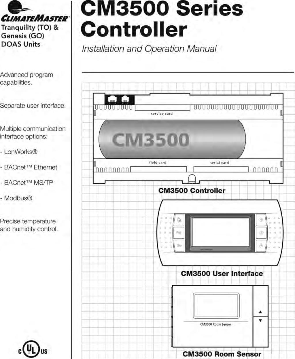
 Advanced program capabilities. Installation and Operation Manual for QS/QV and Aura Units Standard controller with interface mounted in unit. Optional hand-held user interface available. Multiple communication
DOAS CM3500 Controller
 DOAS CM3500 Controller Table of Contents Dehumidification Equipment Standard Limited Warranty 3 Installation 4 IAQ Controller Details 7 Alarms 27 Hardware Details 30 Specifications 33 Points List 37 Revision
TAP v2.10 Version Date: 6/12/13. Document Microprocessor Controller for Tempered Air Products
 Document 475595 Microprocessor Controller for Tempered Air Products Reference Guide for the Microprocessor Controller Please read and save these instructions. Read carefully before attempting to operate
INSTALLATION & OPERATION MANUAL
 INSTALLATION & OPERATION MANUAL Model TME- * * Balance of model number is determined by customer specifi ed limits and Setbacks. AUTOMATIC SETBACK THERMOSTAT LIGHT SENSING OR CONTACT CLOSURE FOR LOW VOLTAGE
DC 60 & DM 60 displays
 USER MANUAL DC 60 & DM 60 displays BALTIC FLEXAIR ENERGY AIRCOOLAIR COMPACTAIR FLATAIR (& Inverter) AQUALEAN DC60-DM60-IOM-1310-E www.lennoxemea.com Summaries 1 Display DC60 1.1 Introduction... 2 1.2
Digital Precise Air Control - DPAC
 Digital Precise Air Control - DPAC Mode Enable Sensor Options The temperature of this sensor will determine if the unit is in heating, cooling or vent mode during Occupied operation. The following options
Reference Guide for Microprocessor Controller
 Document 483586 Microprocessor Controller for Dedicated Outdoor Air System Reference Guide for Microprocessor Controller Please read and save these instructions for future reference. Read carefully before
Reference Guide for Microprocessor Controller
 Document 483232 Microprocessor Controller for Energy Recovery Reference Guide for Microprocessor Controller Please read and save these instructions for future reference. Read carefully before attempting
DAP III Zone Master User s Guide
 DAP III Zone Master User s Guide Data Aire, Inc. 230 West BlueRidge Avenue Orange, California 92865 Document Number 600-000-788 March 2010 Revision 1.0 Document # 600-000-788 1 Overview The Data Aire DAP
ModSync Sequencing System Installation & Operation Manual. For use with Fulton Steam Boilers.
 ModSync Sequencing System Installation & Operation Manual For use with Fulton Steam Boilers. Revision 3.0 8/21/2008 - 2 - Table of Contents Introduction Page 4 Features Page 4 Sequence of Operation Page
INSTALLER S & OWNER S MANUAL
 INSTALLER S & OWNER S MANUAL HVAC INSTALLER: PLEASE LEAVE MANUAL FOR HOMEOWNER DEH 3000R Part No. 4028407 Dehumidifier & Ventilation System Controller 4201 Lien Road, Madison, WI 53704 TOLL-FREE (800)-533-7533
Refrigeration Controller Operator s Manual (HRC) PO Box 6183 Kennewick, WA
 PO Box 6183 Kennewick, WA") Refrigeration Controller Operator s Manual (HRC) PO Box 6183 Kennewick, WA 99336 www.jmcvr.com 1-509-586-9893 Table of Contents TABLE OF FIGURES...1 OVERVIEW OF THE HRC CAPABILITIES...2 INSTALLATION AND
Refrigeration Controller Operator s Manual (HRC) PO Box 6183 Kennewick, WA 99336 www.jmcvr.com 1-509-586-9893 Table of Contents TABLE OF FIGURES...1 OVERVIEW OF THE HRC CAPABILITIES...2 INSTALLATION AND
5+2 DAY. OWNER S MANUAL Venstar Inc. 05/08
 Digital Thermostat residential THERMOSTAT 5+2 DAY PROGRAMMABLE up to 1-heat & 1-cool PUMP Stages: 1-Heat, 1-Cool Battery or System Powered Back-Lit Digital Display Fahrenheit or Celsius Service Filter
1 For All Programmable Digital Thermostat
 OWNER'S MANUAL P/N P374-2300FM 1 For All Programmable Digital Thermostat Am OFF OVERRIDE Meets California Title 24 unts flush to the wall 7 Day Programmable 3 Occupied, 1 Unoccupied Auto-Changeover Large,
INSTALLER S & OWNER S MANUAL
 INSTALLER S & OWNER S MANUAL HVAC INSTALLER: PLEASE LEAVE MANUAL FOR HOMEOWNER Part No. 4028539 Dehumidifier & Ventilation System Controller 4201 Lien Rd Madison, WI 53704 TOLL-FREE 1-800-533-7533 www.thermastor.com
Reference Guide for Microprocessor Controller
 Document 482641 Microprocessor Controller for Make-Up Air Products Reference Guide for Microprocessor Controller Please read and save these instructions for future reference. Read carefully before attempting
I/O ZONE 560/583 USERS GUIDE
 I/O ZONE 560/583 USERS GUIDE 641-224 641-242 641-237 1 Table of Contents Hot Gas Re-Heat Valve On/Off:... 15 THE ZONE CONTROLLER...4 Modulating Re-Heat Valve:... 16 SPECIFICATIONS...5 CONTROLLER COMPONENTS...6
Marvel S MICROPROCESSOR CONTROLLER. Installation, Operation and Maintenance Manual Effective October 2018 DISCONTINUED. For Reference Only
 Marvel S MICROPROCESSOR CONTROLLER Installation, Operation and Maintenance Manual Effective October 2018 DISCONTINUED For Reference Only ***Interactive PDF*** Contents General Purpose...3 Standard And
Custom Control Systems Inc. Ellis Dryer Control Configuration and Operation Manual
 Ellis Dryer Control Configuration and Operation Manual Revised 1/19/2004 Table of Contents 1 Introduction... 7 1.1 Hardware Specifications... 7 1.2 Software Features... 7 1.3 Warranty... 8 1.3.1 Terms...
Owner s Manual. Digital. Heat Pump. 5+2 Day Programmable. Model S1-THEH21P5S HVAC SERVICE PARTS TM
 Owner s Manual Model S1-THEH21P5S HVAC SERVICE PARTS TM Heat Pump 5+2 Programmable Digital T h e rm ostats t a t BACKLIT DISPLAY Use with most Heat Pump systems: 1-Heat, 1-Cool 2-Heat, 1-Cool Control up
Product Manual SZ1022/SZ1031/SZ1035/
 Product Manual SZ1022/SZ1031/SZ1035/ Conventional Heating & Cooling Thermostats Communicating Thermostats Description The SZ1022, SZ1031, and SZ1035, are microprocessorbased mable thermostats designed
Mark 25 Ultrapure Water Conductivity Analyzer
 Martek Instruments, Inc. Mark 25 Ultrapure Water Conductivity Analyzer Instruction Manual WARRANTY POLICY Unless otherwise stated, MARTEK INSTRUMENTS, INC. warrants this equipment to be free from defects
RC-2000 Thermostat Installation Instructions
 RC-2000 Thermostat Installation Instructions DESCRIPTION The RC-2000 is a precision digital thermostat designed for 24 VAC heating and cooling systems. The RC-2000 will support the following systems: Single
ATC32U03 igate Communicating, Programmable Thermostat
 ATC32U03 igate Communicating, Programmable Thermostat User Manual 97B0055N02 Rev.: 11/3/17 Table of Contents Section Title Page Menu Navigation Shortcuts 3 1.0 Operating Mode Selection 3 2.0 Temperature
Product Manual SZ1009
 Product Manual SZ1009 Conventional Heating & Cooling Thermostats with Heat Pump Mode Communicating Thermostats Description The SZ1009 is a microprocessor-based mable thermostats designed for conventional
Owner s Manual. 5+2 Day Programmable Digital Thermostat
 Model Air Conditioning & Heating 5+2 Programmable Digital Thermostat 1-Heat & 1-Cool Heat Pump Compatible Battery or System Powered Backlit Digital Display Fahrenheit or Celsius Service Filter Indicator
Installation Instructions / User s Manual TSTAT0406 and TSTAT0408
 997-060180-5 Installation Instructions / User s Manual TSTAT0406 and TSTAT0408 4 HEAT 2 COOL DUAL FUEL TSTAT0406 & TSTAT0408-4 WIRE CAPABLE THERMOSTAT (NAXA00201DB Daughter Board sold separately) LEFT
SEQUENCE OF OPERATIONS
 SEQUENCE OF OPERATIONS DDC CONTROLLER: Controller with integral LCD readout for changing set points and monitoring unit operation. Provided with required sensors and programming. Factory programmed, mounted,
C-TRAC3 COMMUNICATION MANUAL FOR. BACnet NOVEMBER 2010 TO JANUARY 2014 USA HEAD OFFICE AND FACTORY
 A C-TRAC3 COMMUNICATION MANUAL FOR BACnet NOVEMBER 2010 TO JANUARY 2014 UNIT MODEL NO. UNIT SERIAL NO. SERVICED BY: TEL. NO: CANADIAN HEAD OFFICE AND FACTORY 1401 HASTINGS CRES. SE CALGARY, ALBERTA T2G
ATC32U01 igate Communicating, Programmable Thermostat
 ATC32U01 igate Communicating, Programmable Thermostat User Manual 97B0055N02 Rev.: 7/2/12 Table of Contents Section Title Page Menu Navigation Shortcuts 3 1.0 Operating Mode Selection 3 2.0 Temperature
Safety & Installation Instructions
 Model 8800 Universal Communicating Thermostat Safety & Installation Instructions READ AND SAVE THESE INSTRUCTIONS Table of contents Installation Installation location recommendations... 2 Thermostat mounting...
SC Installation, Operation & Application Guide
 SC 5211 2-Stage Heat Pump Auto Changeover Hardwire Programmable Electronic Thermostat 7-Day, 5-2-Day or 5-1-1-Day Programmable Configurable 2-Stage Heat Pump Systems Large Display With Backlight Selectable
VAV Thermostat Controller Specification and Installation Instructions. Model TRO24T4XYZ1
 Model TRO24T4XYZ1 Description The TRO24T4XYZ1 is a combination controller and thermostat. The VAV Thermostat Controller is designed for simple and accurate control of any variable air volume box in a number
Owner s Manual. Part Number 33CSSP2-FC BACK LIT LIQUID CRYSTAL DISPLAY MODE BUTTON
 Owner s Manual Part Number 33CSSP2-FC 33CS Fan Coil Programmable Thermostat SAFETY CONSIDERATIONS Read and follow manufacturer instructions carefully. Follow all local electrical codes during installation.
7-Day. Digital Thermostat. residential. & 2-cool
 Digital Thermostat residential THERMOSTAT T1100FS 7-Day PROGRAMMABLE up to 2-heat & 2-cool PUMP Control up to 2 Heat & 2 Cool Stages 7-Day Programmable 4 Settings/Day Auto Changeover 5 minute Built-In
Digital Programmable
 www.geappliances.com Digital Programmable Thermostats Operating Instructions Auto Changeover..........10 Day/Time Setting Mode.....6 Default Mode...............4 Fan Control...............10 Hold and Temporary
Owner s Manual. Digital Thermostat
 Model Air Conditioning & Heating Heat Pump 5+2 Day Programmable Digital Thermostat Control up to 2-Heat & 1-Cool Battery or System Powered Backlit Digital Display Auxiliary Heat Indicator Fahrenheit or
Installation, Start-Up, and Operating Instructions
 Installation, Start-Up, and Operating Instructions IMPORTANT: Read entire instructions before starting the installation. SAFETY CONSIDERATIONS Read and follow manufacturer instructions carefully. Follow
AirTrak. Digital Control System. User Manual. Touchscreen Systems
 AirTrak Digital Control System User Manual Touchscreen Systems Rev. 10-29-15 1 2 Table of Contents OVERVIEW... 8 NETWORKING... 9 AIRTRAK DEFAULT SETTINGS... 9 Unit Operating Modes... 10 MRT Controls...
User s Manual
 997-060180-4e User s Manual 8403-060 Menu Driven Display 1120-445 I. CONTROLLER OPERATION ADJUSTING TEMPERATURE (Temporary Override when in Programmable mode) 1. Before you can adjust the temperature,
User s Manual. TIGER S EYE E-Series Mark V Jockey. TIGERFLOW Systems, Inc Mint Way Dallas, Texas
 User s Manual TIGER S EYE E-Series Mark V Jockey TIGERFLOW Systems, Inc. 4034 Mint Way Dallas, Texas 75237 214-337-8780 www.tigerflow.com TABLE OF CONTENTS Introduction... 4 Sequence of Operation... 5
AdaptAire. Digital Control System. User Manual. Expert Systems
 AdaptAire Digital Control System User Manual Expert Systems Rev. 10-29-15 1 2 Table of Contents OVERVIEW... 8 NETWORKING... 10 ADAPTAIRE DEFAULT SETTINGS... 10 UNIT OPERATING MODES... 11 MRT Controls:...
Owner s Manual. Digital Thermostat. Heat/Cool & Heat Pump 7-Day Programmable S1-THEM22P7S COMMERCIAL. Model HVAC SERVICE PARTS
 Owner s Manual Model COMMERCIAL TM BACKLIT DISPLAY HVAC SERVICE PARTS Heat/Cool & Heat Pump 7-Day Programmable Digital Thermostat Use with most Heat Pump Systems: 2-Heat, 2-Cool Stages: 2-Heat, 2-Cool
NCU Mounting Details
 Revision Date December 4, 2013 RS-485 Modbus RTU Networking Room Thermostats with LCD for Fan Coil Units Installation and Operation Instructions Dimensions in mm Power Control Unit Display Control Unit
T600MEP-2 Programmable Economizer Thermostat
 Installation Instructions Issue Date January 19, 2005 T600MEP-2 Programmable Economizer Thermostat Application The T600MEP-2 is a programmable thermostat for control of single- or two-stage unitary rooftop
Tri-Stack Smart System
 Tri-Stack Smart System TM Notes & Warnings - The protection provided by this equipment may be impaired if it is not used in the manner specified herein. - Ensure all wiring meets applicable national and
For Quick Set-Up go to Page 14
 Talking Thermostat Model VT3000 Guide SmartWay Solutions, Inc. US Patent 6,608,560 & 7,62,253 For Quick Set-Up go to Page 4 Model VT3000, a universal thermostat for use on most Gas or Electric, Conventional
Marvel J MICROPROCESSOR CONTROLLER
 Marvel J MICROPROCESSOR CONTROLLER Installation, Operation and Maintenance Manual Effective August 2016 ***Interactive PDF*** Contents General Purpose... 3 Standard Components... 3 Number of I/O Allowable...
Verasys System Operation Overview Technical Bulletin
 Contents subject to change. Verasys System Operation Overview Technical Bulletin Code No. LIT-12012370 Issued January 2016 Refer to the QuickLIT Web site for the most up-to-date version of this document.
1.0 Digital Controller
 1.0 Digital Controller...1 1.1 Display Function Keys...1 1.2 Thermostat Display...2 1.3 Controller hardware input output points... 4 2.0 Sequence of Operation...5 2.1 States of Operation...5 2.2 Modes
Networkable Fan Coil Controller Specification and Installation Instructions
 Controller Models EFCB10T-OE1 (24Vac / 0 relays) EFCB12T-OE1 (240Vac / 0 relays) EFCB10TU4-OE1 (24Vac / 4 relays) EFCB12TU2-OE1 (240Vac / 2 relays) EFCB12TU4-OE1 (240Vac / 4 relays) TFL Series Thermostat
User Manual. Dryer Controller M720
 User Manual Dryer Controller M720 Hardware version 1.00 Software version 1.00 Preliminary version Manual M720 Dryer controller Page 1 of 42 Document history Preliminary version: - Created in April, 2009
SCIENTIFIC WARMING CABINET Installation, Operation and Maintenance Instructions
 SCIENTIFIC WARMING CABINET Installation, Operation and Maintenance Instructions GENERAL 2 Inspection 2 Location 2 INSTALLATION 2 Door Alignment 2 Shelf Installation 2 Remote Contacts 3 2-10 Volt DC Output
0 C to 50 C ( 32 F to 122 F ) 0% to 95% R.H. non-condensing. 30 to 95% R.H. Dry contact across terminal BI1, BI2 & UI3 to Scom
 0% to 95% R.H. non-condensing. 30 to 95% R.H. Dry contact across terminal BI1, BI2 & UI3 to Scom") Viconics VT7350 Series PIR Ready Fan-coil Controllers General The VT7350 series are PIR Ready low-voltage microprocessor-based fan-coil controllers. Models are available controlling single speed and multi-speed
Viconics VT7350 Series PIR Ready Fan-coil Controllers General The VT7350 series are PIR Ready low-voltage microprocessor-based fan-coil controllers. Models are available controlling single speed and multi-speed
SC Installation, Operation & Application Guide
 SC 3006 Auto Changeover 7-Day Programmable Hardwired Programmable Electronic Thermostat 7-Day Programmable Single Stage Heat Pump/Non-Heat Pump Systems Backlit Display Single Stage Heat/Cool Systems Field
TEC2620 Series Non-Programmable Fan Coil Network Thermostat Controller and Remote I/O Relay Packs
 TEC2620 Series Non-Programmable Fan Coil Network Thermostat ler and Remote I/O Relay Packs TEC2620H-0, TEC2620C-0, TEC2620H-0+PIR, TEC2620C-0+PIR, TEC2621H-0, TEC2621C-0, TEC2621H-0+PIR, TEC2621C-0+PIR
Fan Coil Thermostat Controller Specification and Installation Instructions. Model TFHB24F3XYZ1 with External Humidity Sensor and BACnet Communication
 Model TFHB24F3XYZ1 with External Humidity Sensor and BACnet Communication Description The TFHB24F3XYZ1 is a fully configurable controller designed specifically for 2 pipe and 4 pipe fan coil applications.
Installation and Operation. Tracer ZN521 Zone Controller CNT-SVX07C-EN
 Installation and Operation Tracer ZN521 Zone Controller CNT-SVX07C-EN Installation and Operation Tracer ZN521 Zone Controller CNT-SVX07C-EN April 2005 CNT-SVX07C-EN Tracer ZN521 Zone Controller Installation
VENSTAR T1075 FAN COIL THERMOSTAT 7 DAY PROGRAMMABLE 2 OR 4 PIPE SYSTEMS OWNER S MANUAL AND INSTALLATION INSTRUCTIONS
 VENSTAR FAN COIL THERMOSTAT FAN COIL THERMOSTAT T1075 7 DAY PROGRAMMABLE 2 OR 4 PIPE SYSTEMS 3 Occupied, 1 Unoccupied Override capable 3 speed fan control Auto 2-pipe changeover when used with accessory
T-32-TS Touchscreen Thermostat. Installation Manual
 T-32-TS Touchscreen Thermostat Installation Manual TABLE OF CONTENTS Introduction...4 Getting Started...5 Installing the Thermostat...6, 8 Disassembly...6 Thermostat Location...6 Mounting the Subbase...6,
1.0 Digital Controller
 Form CP-AHU D19_D21_D22 (11-17) D303072-A Obsoletes Forms CP-Preeva-D21 (1-16) Doc No 303072, CP-Preeva-D19 (1-16) Doc No 303071 Applies to: Preeva, MAPS, MAPS II, RPB, RPBL & SSCBL Series For Air Handler
SC Installation, Operation & Application Guide
 SC 5811 2 Heat/2 Cool Auto Changeover Hardwire Programmable Electronic Thermostat 7-Day, 5-2-Day or 5-1-1-Day Programmable Configurable 2-Stage Heat/2-Stage Cool Systems 2-Stage Heat Pump Systems Large
Thermostats. Digital Programmable. GEAppliances.com
 GEAppliances.com Digital Programmable Thermostats Owner s Manual & Installation Instructions RAK148P2 RAK164P2 Configuration Mode...8 9 Important Safety Information... 2 Installation Instructions... 4
T60xDFH-4 and T60xDFH-4+PIR Series Thermostat Controllers with Dehumidification and Occupancy Sensing Capability
 T60xDFH-4 and T60xDFH-4+PIR Series Thermostat Controllers with Dehumidification and Occupancy Sensing Capability Product Bulletin T601DFH-4, T602DFH-4, T603DFH-4, T604DFH-4, T605DFH-4, T601DFH-4+PIR, T602DFH-4+PIR,
Carbon Monoxide Transmitter
 Introduction The CO Transmitter uses an electrochemical sensor to monitor the carbon monoxide level and outputs a field-selectable 4-20 ma or voltage signal. The voltage signal may also be set to 0-5 or
Dryer Controller M720
 User Manual Dryer Controller M720 Hardware version 2.00 Software version 2.00 Manual M720 Dryer controller Page 1 of 60 Document history Preliminary version: - Created in April, 2009 Hardware Version 2.00,
QD-ENG-68 Controller for Thermoelectric Thermal Management
 INSTALLING THE CONTROLLER QD-ENG-68 Controller for Thermoelectric Thermal Management The Ice Qube TMS controller is shipped complete with mounting hardware and electrical cables for easy installation.
Operating Instructions READ AND SAVE THESE INSTRUCTIONS
 Operating Instructions READ AND SAVE THESE INSTRUCTIONS Aprilaire Communicating Thermostat Model 8870 CAUTION: Do not set to OFF mode during periods when freezing temperatures could occur. Thank you for
WIRING DIAGRAMS R410A MODELS PAC 2OAC/2OACH CAC OWC PWC
 WIRING DIAGRAMS R410A MODELS 2OAC/2OACH PAC CAC PWC OWC WIRING 02172017 TABLE OF CONTENTS PAGE 2OACH Deluxe Portable Air-cooled Heat Pump Electronic Controller... 2-3 Piping Schematic... 4 Single Phase
VENSTAR T1070 FAN COIL THERMOSTAT PROGRAMMABLE 2 OR 4 PIPE SYSTEMS OWNER S MANUAL AND INSTALLATION INSTRUCTIONS
 VENSTAR FAN COIL THERMOSTAT FAN COIL THERMOSTAT T1070 NON- PROGRAMMABLE 2 OR 4 PIPE SYSTEMS Remote sensor ready 3 speed fan control Self-prompting adjustment Auto 2-pipe changeover when used with ACC-SENFC
Rev Pulse Modulating and Anti- Sweat Control (PMAC II Solo) Installation and Operation Manual
 Installation and Operation Manual") 026-1503 Rev 0 3-20-03 Pulse Modulating and Anti- Sweat Control (PMAC II Solo) Installation and Operation Manual 1640 Airport Road, Suite 104 Kennesaw, GA 31044 Phone: (770) 425-2724 Fax: (770) 425-9319
026-1503 Rev 0 3-20-03 Pulse Modulating and Anti- Sweat Control (PMAC II Solo) Installation and Operation Manual 1640 Airport Road, Suite 104 Kennesaw, GA 31044 Phone: (770) 425-2724 Fax: (770) 425-9319
Document # R01
 Viconics VT7600 Series PIR-Ready Rooftop Unit Controllers Part 1 General The VT7600 series is designed for single-stage and multi-stage control of heating/cooling equipment such as rooftop and self-contained
*IG1583EW* Aurora Touch UPC Kit Instruction Guide. Aurora Touch UPC Kit Instruction Guide
 Aurora Touch UPC Kit Instruction Guide For use in single compressor water-to-air equipment utilizing fi rmware UPCSWASTD01-01 Aurora Touch UPC Kit Instruction Guide *IG1583EW* IG1583EW 08/14 Aurora Touch
Installation, Configuration and User Manual
 Model 8826 System Controller Model 8826 System Controller Installation, Configuration and User Manual READ AND SAVE THESE INSTRUCTIONS WELCOME Thank you for choosing the Aprilaire HVAC Automation System.
SECTION SEQUENCE OF OPERATIONS FOR HVAC CONTROLS
 PART 1 - GENERAL SECTION 23 09 93 SEQUENCE OF OPERATIONS FOR HVAC CONTROLS 1.1 SUMMARY A. This Section includes control sequences for HVAC systems, subsystems, and other equipment. B. See Division 23 Section
OWNER S MANUAL Venstar Inc. 08/07
 Digital Thermostat commercial SCHOOL THERMOSTAT T2900SCH MABLE up to 3-heat & 2-cool HEAT COOL HEAT PUMP Energy Saving Operation Morning Warm-up Period Programmable Override Unoccupied until button press
HAI Omni-Bus Network Installation. 5. Typical Application
 HAI Omni-Bus Network Installation 5. Typical Application HAI Omni-Bus Network Installation Notes 1. Network cable 2. Crimp Connectors 3. Network Termination Plug 4. Jumpers 5. Splitters 6. Power Supply
ZonexCommander. ZonexCommander(Plus) Installation and Applications Manual. Network All Your HVAC Equipment
 Installation and Applications Manual. Network All Your HVAC Equipment") ZonexCommander ZonexCommander(Plus) Network All Your HVAC Equipment Centralized DDC Communications for Stand-Alone HVAC and Zoned Systems Installation and Applications Manual Part #ZCMAN Rev. Oct 2014
ZonexCommander ZonexCommander(Plus) Network All Your HVAC Equipment Centralized DDC Communications for Stand-Alone HVAC and Zoned Systems Installation and Applications Manual Part #ZCMAN Rev. Oct 2014
Analog Room Pressure Monitor RPC Series
 Description The Room Pressure Monitor is used to measure differential pressure in the range of 0.125 to 1"wc or 30 to 250 Pa. It combines precision high sensitivity silicon sensing capabilities and the
AdaptAire. Digital Control System. User Manual
 AdaptAire Digital Control System User Manual Rev. 10-22-07 1 Table of Contents OVERVIEW... 6 NETWORKING... 7 ADAPTAIRE DEFAULT SETTINGS... 7 UNIT OPERATING MODES... 8 MDT Controls:... 8 UNIT OFF MODE...8
Installation and Operations Manual
 Installation and Operations Manual H-IM-LLC February 2018 Part No. 25092501 Replaces H-IM-LLC (01/2014) Lead Lag Control System Table of Contents General Safety Information 2 Inspection 2 Warranty Statement
MicroTech Self-Contained Air Conditioning System
 Open Protocol Data Information Packet Version 2.3 Group: Controls Date: October 1999 MicroTech Self-Contained Air Conditioning System Open Protocol Data Communications t 2002 McQuay International - C O
TMC. Installation and Operation Manual TMC. Temperature and Pressure Monitoring for Heating and Cooling Applications. Temperature Monitoring Control
 Installation and Operation Manual Temperature and Pressure Monitoring for Heating and Cooling Applications Temperature Monitoring Control VALVE OPEN ALARM System= 128 o F Alarm At= 130 o F RESET /BACK
DAY/TIME Button: Selects hour, minute and day setting.
 MODEL 5300 USER MANUAL READ ALL INSTRUCTIONS BEFORE PROCEEDING For more information on energy savings, go to www.energystar.gov Premier Series Universal Auto Changeover Thermostat Up to 2 Heat / 2 Cool
Programmable 5-2 Day Digital Thermostat
 Programmable 5-2 Day Digital Thermostat 1 STAGE HEAT COOL THERMOSTAT TOTALINE 72 72 prog run off set Tu Heat I2:00 next SINGLE STAGE HEAT PUMP COMPATIBLE (Does not control auxiliary heat) Separate programs
CELLTROL II BIOREACTOR CONTROL SYSTEM OPERATIONS MANUAL
 Operation Manual Celltrol II Bioreactor Control System Page 1 of 33 Table of Contents 1) Introduction... 3 1.1) Scope of Document... 3 1.2) Control System Overview... 3 1.3) Introduction to Celltrol II...
SC Installation, Operation & Application Guide
 SC 3801 2 Heat/2 Cool 7-Day Programmable Hardwired Programmable Electronic Thermostat Programmable and Configurable Single/Dual Stage Heat Pump Systems Single/Dual Stage Heat/Cool Systems Backlit Display
Instruction, Operation, and Maintenance: Controls Software Versions: R37+
 Instruction, Operation, and Maintenance: Controls Software Versions: R37+ VPR Series VPRX Series VPRE Series VPRP Series Version October 2011 Table of Contents Safety... 3 Special Design Requests... 3
RPM1600 Series Room Pressure Monitors
 RPM1600 Series Room Pressure Monitors Technical Bulletin LB-RPM1611-0, LB--0 Code No. LIT-12012228 Issued October 2017 Refer to the QuickLIT website for the most up-to-date version of this document. How
AireLogic. Digital Control System. User Manual
 AireLogic Digital Control System User Manual Rev. 04-11-13 1 Table of Contents OVERVIEW... 6 NETWORKING... 8 AIRELOGIC DEFAULT SETTINGS... 8 UNIT OPERATING MODES... 9 MRT Controls:... 9 UNIT OFF MODE...
RC-112 Two Speed Heat Pump 3 Stage Heat / 2 Stage Cool With Energy Efficient Control
 O M N I S T A T ELECTRONIC COMMUNICATING THERMOSTAT Installation Manual RC-112 Two Speed Heat Pump 3 Stage Heat / 2 Stage Cool With Energy Efficient Control Document Number 13I00-5 November, 1997 CONTENTS
OVEN INDUSTRIES, INC.
 OVEN INDUSTRIES, INC. OPERATING MANUAL Model 5C7-252 TEMPERATURE CONTROLLER With PLC Inputs Introduction Thank you for purchasing our controller. The Model 5C7-252 is an exceptionally versatile unit and
HEAT COOL. Meets Commercial California Title 24
 Digital Thermostat commercial THERMOSTAT T2900 7-DAY MABLE up to 3-heat & 2-cool HEAT COOL HEAT PUMP Control up to 3 Heat & 2 Cool Stages 3 Configurable Outputs Adjustable 2nd & 3rd Stage Timers & Deadbands
Installation and Maintenance Manual IM
 Installation and Maintenance Manual IM 1234-1 BACnet Thermostat Group: Applied Air Systems Part Number: IM 1234 Date: December 2014 Use with Daikin MicroTech Integrated Systems or as standalone Table of
SECTION SEQUENCE OF OPERATIONS FOR HVAC CONTROLS
 SECTION 23 09 93 SEQUENCE OF OPERATIONS FOR HVAC CONTROLS PART 1 - GENERAL 1.1 SUMMARY A. This Section includes control sequences for HVAC systems, subsystems, and equipment. B. See Division 23 Section
REMOTE CONTROL FOR CHILLER MYCHILLER
 REMOTE CONTROL FOR CHILLER MYCHILLER GENERAL FEATURES... 3 MAIN FUNCTIONS AND EQUIPMENT:... 3 LCD DISPLAY... 4 KEYBOARD... 5 BOARD CONFIGURATION... 7 LIST OF MAIN PARAMETERS... 7 CONFIGURATION OF MAIN
Pioneer Gold Controller Technical Guide
 Pioneer Gold Controller Technical Guide Pioneer Gold Controller Code: Version 1.03 Electric Heat Expansion Module Code: Version 1.0 Used with AAON WSHP WV Series Vertical and WH Series Horizontal This
IMPORTANT SAFETY INFORMATION:
 Owner s Manual Model CX-MPC IMPORTANT SAFETY INFORMATION: Always read this manual first before attempting to install or use this device. For your safety, always comply with all warnings and safety instructions
INSTALLATION MANUAL. * If using remote sensors the thermostat must be hardwired. Need Help?
 INSTALLATION MANUAL This manual covers the following models: T955W Master Thermostat Base Module Thermostat Applications Guide Description Gas or Oil Heat Electric Furnace Heat Pump (No Aux. or Emergency
Rev Pulse Modulating Anti- Sweat Control (PMAC II) Installation and Operation Manual
 Installation and Operation Manual") 026-1501 Rev 5 3-20-03 Pulse Modulating Anti- Sweat Control (PMAC II) Installation and Operation Manual 1640 Airport Road, Suite 104 Kennesaw, GA 31044 Phone: (770) 425-2724 Fax: (770) 425-9319 ALL RIGHTS
026-1501 Rev 5 3-20-03 Pulse Modulating Anti- Sweat Control (PMAC II) Installation and Operation Manual 1640 Airport Road, Suite 104 Kennesaw, GA 31044 Phone: (770) 425-2724 Fax: (770) 425-9319 ALL RIGHTS