Report on Proposals A2006 Copyright, NFPA NFPA 13 Report of the Committee on
|
|
|
- Eleanore McGee
- 6 years ago
- Views:
Transcription
1 Report of the Committee on use of central station, proprietary, auxiliary, and local signaling systems for watchmen, fire alarm, supervisory service, nor the design of fire department Automatic Sprinkler Systems (AUT-AAC) hose connections. Technical Correlating Committee John G. O Neill, Chair The Protection Engineering Group, PC, VA [SE] Christian Dubay, Nonvoting Secretary National Fire Protection Association, MA Jose R. Baz, International Engineered Systems Limited, Incorporated, FL [M] Rep. NFPA Latin American Section Kerry M. Bell, Underwriters Laboratories Incorporated, IL [RT] Russell P. Fleming, National Fire Sprinkler Association, NY [M] Scott T. Franson, The Viking Corporation, MI [M] Raymond A. Grill, The RJA Group, Incorporated, VA [SE] James B. Harmes, Grand Blanc Fire Department, MI [E] Rep. International Association of Fire Chiefs Luke Hilton, Liberty Mutual Property, FL [I] Alex Hoffman, Viking Fire Protection Incorporated, Canada [IM] Rep. Canadian Automatic Sprinkler Association Roland J. Huggins, American Fire Sprinkler Association, Incorporated, TX [IM] Sultan M. Javeri, SC Engineering, France [IM] Andrew Kim, National Research Council of Canada, Canada [RT] Joe W. Noble, Clark County Fire Department, NV [E] Rep. International Fire Marshals Association Eric Packard, Local 669 JATC Education Fund, MD [L] Rep. United Association of Journeymen & Apprentices of the Plumbing & Pipe Fitting Industry of the US & Canada Chester W. Schirmer, Schirmer Engineering Corporation, NC [I] Robert D. Spaulding, FM Global, MA [I] Rep. FM Global Lynn K. Underwood, Axis US Property, IL [I] Alternates Donald Don D. Becker, RJC & Associates, Incorporated, MO [IM] (Alt. to Roland J. Huggins) George Capko, Jr., FM Global, MA [I] (Alt. to Robert D. Spaulding) Randall S. Chaney, Liberty Mutual Property, CA [I] (Alt. to Luke Hilton) Kenneth E. Isman, National Fire Sprinkler Association, NY [M] (Alt. to Russell P. Fleming) George E. Laverick, Underwriters Laboratories Incorporated, IL [RT] (Alt. to Kerry M. Bell) Donald C. Moeller, The RJA Group, Incorporated, CA [SE] (Alt. to Raymond A. Grill) Garner A. Palenske, Schirmer Engineering Corporation, CA [I] (Alt. to Chester W. Schirmer) Donato A. Pirro, Electro Sistemas De Panama, S.A., Panama [M] (Alt. to Jose R. Baz) J. Michael Thompson, The Protection Engineering Group, PC, VA [SE] (Alt. to John G. O Neill) Nonvoting Antonio C. M. Braga, FM Global, CA [I] Rep. TC on Hanging & Bracing of Water-Based Systems Edward K. Budnick, Hughes Associates, Incorporated, MD [SE] Rep. TC on Sprinkler System Discharge Criteria Robert M. Gagnon, Gagnon Engineering, MD [SE] Rep. TC on Foam-Water Sprinklers William E. Koffel, Koffel Associates, Incorporated, MD [SE] Rep. Safety to Life Correlating Committee Kenneth W. Linder, GE Global Asset Protection Services, CT [I] Rep. TC on Sprinkler System Installation Criteria Daniel Madrzykowski, US National Institute of Standards & Technology, MD [RT] Rep. TC on Residential Sprinkler Systems J. William Sheppard, General Motors Corporation, MI [U] Rep. TC on Private Water Supply Piping Systems John J. Walsh, UA Joint Apprenticeship Committee, MD [SE] (Member Emeritus) Committee Scope: This Committee shall have overall responsibility for documents that pertain to the criteria for the design and installation of automatic, open and foam-water sprinkler systems including the character and adequacy of water supplies, and the selection of sprinklers, piping, valves, and all materials and accessories. This Committee does not cover the installation of tanks and towers, nor the installation, maintenance, and Report of the Committee on Hanging and Bracing of Water-Based Fire Protection Systems (AUT-HBS) Antonio C. M. Braga, Chair FM Global, CA [I] Rep. FM Global Samuel S. Dannaway, Secretary S. S. Dannaway Associates, Incorporated, HI [SE] James B. Biggins, Marsh Risk Consulting, IL [I] Richard W. Bonds, Ductile Iron Pipe Research Association, AL [M] James Dockrill, Troy Sprinkler Limited, Canada [IM] Rep. Canadian Automatic Sprinkler Association Daniel C. Duggan, Fire Sprinkler Design, MO [M] Thomas J. Forsythe, Hughes Associates, Incorporated, CA [SE] John D. Gillengerten, State of California, CA [E] Rep. Building Seismic Safety Council/Code Resource Support Committee Luke Hilton, Liberty Mutual Property, FL [I] Rep. Property Casualty Insurers Association of America Terry Holst, Tyco/Grinnell Fire Protection Systems Company, CA [M] Rep. National Fire Sprinkler Association Tina Marie King, GE Global Asset Protection Services, CA [I] Kraig Kirschner, AFCON, CA [M] Alan R. Laguna, Merit Sprinkler Company, Incorporated, LA [IM] George E. Laverick, Underwriters Laboratories Incorporated, IL [RT] Philip D. LeGrone, Risk Management Solutions, Incorporated, TN [SE] Michael J. Madden, Gage-Babcock & Associates, Incorporated, CA [SE] Wayne M. Martin, Wayne Martin & Associates Incorporated (WMA), CA [SE] J. Scott Mitchell, American Fire Sprinkler Association, TX [M] Donald C. Moeller, The RJA Group, Incorporated, CA [SE] David S. Mowrer, HSB Professional Loss Control, TN [I] Randy R. Nelson, PE, VFS Fire & Security Services, CA [IM] Rep. American Fire Sprinkler Association Janak B. Patel, Bechtel Savannah River Company, GA [U] Michael A. Rothmier, UA Joint Apprenticeship Committee, CO [L] Rep. United Association of Journeymen & Apprentices of the Plumbing & Pipe Fitting Industry of the US & Canada James Tauby, Mason Industries, Incorporated, NY [M] Jack W. Thacker, Allan Automatic Sprinkler Corporation of Southern California, CA [IM] Rep. National Fire Sprinkler Association Victoria B. Valentine, National Fire Sprinkler Association, NY [M] Alternates Charles Bamford, Bamford Incorporated, WA [IM] (Alt. to Randy R. Nelson) Randall S. Chaney, Liberty Mutual Property, CA [I] (Alt. to Luke Hilton) Sheldon Dacus, Security Fire Protection Company, TN [M] (Alt. to Victoria B. Valentine) Christopher I. Deneff, FM Global, RI [I] (Alt. to Antonio C. M. Braga) Todd A. Dillon, GE Global Asset Protection Services, OH [I] (Alt. to Tina Marie King) Paul A. Hart, ERICO, Incorporated, OH [M] (Alt. to J. Scott Mitchell) Russell G. Hoeltzel, Marsh Risk Consulting, CA [I] (Alt. to James B. Biggins) Emil W. Misichko, Underwriters Laboratories Incorporated, IL [RT] (Alt. to George E. Laverick) Eric Packard, Local 669 JATC Education Fund, MD [L] (Alt. to Michael A. Rothmier) Allyn J. Vaughn, The RJA Group, Incorporated, NV [SE] (Alt. to Donald C. Moeller) George Von Gnatensky, Tolco, CA [M] (Alt. to Terry Holst) Ronald N. Webb, S.A. Comunale Company, Incorporated, OH [IM] (Alt. to Jack W. Thacker) 13-1
2 Committee Scope: This Committee shall have the primary responsibility Report of the Committee on for those portions of NFPA 13 that pertain to the criteria for the use and installation of components and devices used for the support of water-based fire Residential Sprinkler Systems (AUT-RSS) protection system piping including protection against seismic events. Daniel Madrzykowski, Chair Report of the Committee on US National Institute of Standards & Technology, MD [RT] Private Water Supply Piping Systems (AUT-PRI) J. William Sheppard, Chair General Motors Corporation, MI [U] Rep. NFPA Industrial Fire Protection Section Christian Dubay, Nonvoting Secretary National Fire Protection Association, MA James B. Biggins, Marsh Risk Consulting, IL [I] Richard W. Bonds, Ductile Iron Pipe Research Association, AL [M] Phillip A. Brown, American Fire Sprinkler Association, Incorporated, TX [IM] Richard R. Brown, Brown Sprinkler Corporation, KY [IM] Rep. National Fire Sprinkler Association Stephen A. Clark, Jr., Allianz Risk Consultants, GA [I] Brandon W. Frakes, GE Global Asset Protection Services, NC [I] Robert M. Gagnon, Gagnon Engineering, MD [SE] David M. Gough, Global Risk Consultants Corporation, CT [SE] Luke Hilton, Liberty Mutual Property, FL [I] Rep. Property Casualty Insurers Association of America Gerald Kelliher, Westinghouse Savannah River Company, SC [U] Kevin J. Kelly, National Fire Sprinkler Association, NY [M] Marshall A. Klein, Marshall A. Klein & Associates, Incorporated, MD [SE] Alan R. Laguna, Merit Sprinkler Company, Incorporated, LA [IM] John Lake, Marion County Fire Rescue, FL [E] George E. Laverick, Underwriters Laboratories Incorporated, IL [RT] James M. Maddry, James M. Maddry, P.E., GA [SE] Kevin D. Maughan, Tyco Fire & Building Products, RI [M] David S. Mowrer, HSB Professional Loss Control, TN [I] Robert A. Panero, Pacific Gas and Electric Company, CA [U] Rep. Edison Electric Institute Sam (Sat) Salwan, Environmental Systems Design, Incorporated, IL [SE] James R. Schifiliti, Fire Safety Consultants, Incorporated, IL [IM] Rep. Illinois Fire Prevention Association James W. Simms, The RJA Group, Incorporated, CA [SE] Alternates Mark A. Bowman, GE Global Asset Protection Services, OH [I] (Alt. to Brandon W. Frakes) James K. Clancy, The RJA Group, Incorporated, CA [SE] (Alt. to James W. Simms) W. Clark Gey, Wayne Automatic Fire Sprinklers, Incorporated, FL [IM] (Alt. to Richard R. Brown) David M. Hammerman, Marshall A. Klein and Associates, Incorporated, MD [SE] (Alt. to Marshall A. Klein) Charles F. Hill, Ryan Fire Protection, Incorporated, IN [M] (Alt. to Kevin J. Kelly) Blake M. Shugarman, Underwriters Laboratories Incorporated, IL [RT] (Alt. to George E. Laverick) Lawrence Thibodeau, Hampshire Fire Protection Company Incorporated, NH [IM] (Alt. to Phillip A. Brown) Nonvoting Geoffrey N. Perkins, Bassett Consulting Engineers, Australia [SE] Committee Scope: This Committee shall have the primary responsibility for documents on private piping systems supplying water for fire protection and for hydrants, hose houses, and valves. The Committee is also responsible for documents on fire flow testing and marking of hydrants. Christian Dubay, Nonvoting Secretary National Fire Protection Association, MA George W. Baker, Mashpee Fire & Rescue Department, MA [E] Rep. International Association of Fire Chiefs Kerry M. Bell, Underwriters Laboratories Incorporated, IL [RT] Fred Benn, Advanced Automatic Sprinkler, Incorporated, CA [IM] Jonathan C. Bittenbender, REHAU Incorporated, VA [M] Frederick C. Bradley, FCB Engineering, GA [SE] Lawrence Brown, National Association of Home Builders, DC [U] Phillip A. Brown, American Fire Sprinkler Association, Incorporated, TX [IM] Edward K. Budnick, Hughes Associates, Incorporated, MD [SE] Thomas G. Deegan, The Viking Group, Incorporated, MI [M] Rep. National Fire Sprinkler Association Kenneth E. Isman, National Fire Sprinkler Association, NY [M] Gary L. Johnson, Noveon, Incorporated, VA [M] Rep. Committee for Firesafe Dwellings David Killey, Fire Busters Incorporated, Canada [IM] Rep. Canadian Automatic Sprinkler Association Alan G. Larson, Uponor Wirsbo Company Incorporated, MN [M] M. L. Larry Maruskin, US Department of Homeland Security, MD [C] Ronald G. Nickson, National Multi Housing Council, DC [U] Eric Packard, Local 669 JATC Education Fund, MD [L] Rep. United Association of Journeymen & Apprentices of the Plumbing & Pipe Fitting Industry of the US & Canada Maurice M. Pilette, Mechanical Designs Limited, MA [SE] Chester W. Schirmer, Schirmer Engineering Corporation, NC [I] Harry Shaw, Fail Safe Safety Systems Incorporated, MD [M] Sandra Stanek, Rural/Metro Fire Department, AZ [E] George W. Stanley, Wiginton Fire Systems, FL [IM] Rep. National Fire Sprinkler Association Randolph W. Tucker, The RJA Group, Incorporated, TX [SE] Ed Van Walraven, Aspen Fire Protection District, CO [E] Terry L. Victor, Tyco/SimplexGrinnell, MD [M] Hong-Zeng (Bert) Yu, FM Global, MA [I] Alternates David W. Ash, Noveon, Incorporated, OH [M] (Alt. to Gary L. Johnson) James K. Clancy, The RJA Group, Incorporated, CA [SE] (Alt. to Randolph W. Tucker) Mark E. Fessenden, Tyco Fire & Building Products, RI [M] (Alt. to Terry L. Victor) Ron Fletcher, Aero Automatic Sprinkler Company, AZ [IM] (Alt. to Phillip A. Brown) David B. Fuller, FM Approvals, RI [I] (Alt. to Hong-Zeng (Bert) Yu) W. Clark Gey, Wayne Automatic Fire Sprinklers, Incorporated, FL [IM] (Alt. to George W. Stanley) Franz P. Haase, Uponor Wirsbo Company Incorporated, NH [M] (Alt. to Alan G. Larson) George E. Laverick, Underwriters Laboratories Incorporated, IL [RT] (Alt. to Kerry M. Bell) Thomas L. Multer, Reliable Automatic Sprinkler Company, GA [M] (Alt. to Thomas G. Deegan) Ron Murray, Plumbers and Steamfitters Local 290 (UA), OR [L] (Alt. to Eric Packard) Steven R. Rians, Standard Automatic Fire Enterprises, Incorporated, TX [IM] (Voting Alt. to AFSA Rep.) David W. Stroup, US National Institute of Standards & Technology, MD [RT] (Alt. to Daniel Madrzykowski) Joseph E. Wiehagen, National Association of Home Builders, MD [U] (Alt. to Lawrence Brown) James V. C. Yates, West Windsor Emergency Services, NJ [E] (Alt. to George W. Baker) 13-2
3 Nonvoting George W. Stanley, Wiginton Fire Systems, FL [IM] (Alt. to Jack W. Thacker) Rohit Khanna, US Consumer Product Safety Commission, MD [C] Peter W. Thomas, Tyco Fire & Building Products, RI [M] (Alt. to James E. Golinveaux) Committee Scope: This Committee shall have primary responsibility for William P. Thomas, Jr., TVA Fire and Life Safety, Incorporated, IL [U] documents on the design and installation of automatic sprinkler systems (Alt. to William J. Tomes) in dwellings and residential occupancies up to and including four stories Tom Vincent, Life Safety Systems, Canada [IM] in height, including the character and adequacy of water supplies, and the (Alt. to Larry Keeping) selection of sprinklers, piping, valves, and all materials and accessories. Martin H. Workman, The Viking Group, Incorporated, MI [M] (Alt. to Thomas G. Deegan) Report of the Committee on Nonvoting Sprinkler System Discharge Criteria (AUT-SSD) Edward K. Budnick, Chair Hughes Associates, Incorporated, MD [SE] Christian Dubay, Nonvoting Secretary National Fire Protection Association, MA Barry M. Lee, Tyco International, Australia [M] Committee Scope: This Committee shall have primary responsibility for those portions of NFPA 13 that pertain to the classification of various fire hazards and the determination of associated discharge criteria for sprinkler systems employing automatic and open sprinklers. Charles O. Bauroth, Liberty Mutual Property, MA [I] Rep. Property Casualty Insurers Association of America Kerry M. Bell, Underwriters Laboratories Incorporated, IL [RT] Michael H. Blumenthal, Rubber Manufacturers Association, DC [M] James C. Bollier, Road Sprinkler Fitters UA Local 483, CA [L] Rep. United Association of Journeymen & Apprentices of the Plumbing & Pipe Fitting Industry of the US & Canada Thomas G. Deegan, The Viking Group, Incorporated, MI [M] Russell P. Fleming, National Fire Sprinkler Association, NY [M] James G. Gallup, The RJA Group, Incorporated, AZ [SE] James E. Golinveaux, Tyco Fire & Building Products, RI [M] Joseph B. Hankins, Jr., FM Global Research, MA [I] Roland J. Huggins, American Fire Sprinkler Association, Incorporated, TX [IM] Sultan M. Javeri, SC Engineering, France [IM] Larry Keeping, Vipond Fire Protection, Canada [IM] Rep. Canadian Automatic Sprinkler Association Andrew Kim, National Research Council of Canada, Canada [RT] William E. Koffel, Koffel Associates, Incorporated, MD [SE] Chris LaFleur, General Motors Corporation, MI [U] Azarang (Ozzie) Mirkhah, Las Vegas Fire and Rescue, NV [E] Richard Pehrson, Futrell Fire Consult and Design, Incorporated, MN [E] Rep. International Fire Marshals Association Chester W. Schirmer, Schirmer Engineering Corporation, NC [I] Michael D. Sides, GE Global Asset Protection Services, FL [I] Peter A. Smith, International Paper Company, TN [U] Sandra Stanek, Rural/Metro Fire Department, AZ [E] David W. Stroup, US National Institute of Standards & Technology, MD [RT] Willie R. Templin, American Automatic Sprinkler, Incorporated, TX [IM] Jack W. Thacker, Allan Automatic Sprinkler Corporation of Southern California, CA [IM] Rep. National Fire Sprinkler Association William J. Tomes, TVA Fire and Life Safety, Incorporated, GA [U] Rep. The Home Depot Alternates Carl P. Anderson, Tacoma Fire Department, WA [E] (Alt. to Azarang (Ozzie) Mirkhah) Weston C. Baker, Jr., FM Global, MA [I] (Alt. to Joseph B. Hankins) Gordon Bates, Minneapolis Fire Department, MN [E] (Alt. to Richard Pehrson) Richard Battista, Fire Protection Industries, Incorporated, NJ [M] (Alt. to Russell P. Fleming) Mark A. Bowman, GE Global Asset Protection Services, OH [I] (Alt. to Michael D. Sides) John August Denhardt, Strickland Fire Protection, Incorporated, MD [IM] (Alt. to Willie R. Templin) Pravinray D. Gandhi, Underwriters Laboratories Incorporated, IL [RT] (Alt. to Kerry M. Bell) Donald Hopkins, Jr., Hughes Associates, Incorporated, MD [SE] (Alt. to Edward K. Budnick) Daniel Madrzykowski, US National Institute of Standards & Technology, MD [RT] (Alt. to David W. Stroup) Jack A. Medovich, East Coast Fire Protection, Incorporated, MD [IM] (Alt. to Roland J. Huggins) Thomas L. Multer, Reliable Automatic Sprinkler Company, GA [M] (Voting Alt. to NFSA Rep.) Garner A. Palenske, Schirmer Engineering Corporation, CA [I] (Alt. to Chester W. Schirmer) Raymond P. Schmid, Koffel Associates, Incorporated, MD [SE] (Alt. to William E. Koffel) Report of the Committee on Sprinkler System Installation Criteria (AUT-SSI) Kenneth W. Linder, Chair GE Global Asset Protection Services, CT [I] Rep. GE Global Asset Protection Services Christian Dubay, Nonvoting Secretary National Fire Protection Association, MA Weston C. Baker, Jr., FM Global, MA [I] Edward K. Budnick, Hughes Associates, Incorporated, MD [SE] Robert G. Caputo, Consolidated Fireprotection, Incorporated, CA [IM] Rep. American Fire Sprinkler Association Jean C. Carter, Jr., Louisiana Office of State Fire Marshal, LA [E] Del Dornbos, The Viking Corporation, MI [M] Rep. National Fire Sprinkler Association Robert E. Duke, Fire Control Incorporated, IL [IM] Randall Eberly, US Coast Guard, DC [E] David L. Foster, Insurance Services Office, Incorporated, NJ [I] Ralph Gerdes, Ralph Gerdes Consultants, LLC, IN [SE] Rep. American Institute of Architects Christopher M. Goddard, AstraZeneca, DE [U] Rep. NFPA Industrial Fire Protection Section Luke Hilton, Liberty Mutual Property, FL [I] Kenneth E. Isman, National Fire Sprinkler Association, NY [M] Larry Keeping, Vipond Fire Protection, Canada [IM] Rep. Canadian Automatic Sprinkler Association Michael D. Kirn, Code Consultants, Incorporated, MO [SE] George E. Laverick, Underwriters Laboratories Incorporated, IL [RT] Ausmus S. Marburger, Fire Protection Industries, Incorporated, PA [IM] Rep. National Fire Sprinkler Association Rodney A. McPhee, Canadian Wood Council, Canada [U] Peter J. McWilliams, Eastman Kodak Company, NY [U] Michael F. Meehan, Virginia Sprinkler Company, Incorporated, VA [IM] Rep. American Fire Sprinkler Association David S. Mowrer, HSB Professional Loss Control, TN [I] Joe W. Noble, Clark County Fire Department, NV [E] Rep. International Fire Marshals Association Eric Packard, Local 669 JATC Education Fund, MD [L] Rep. United Association of Journeymen & Apprentices of the Plumbing & Pipe Fitting Industry of the US & Canada Chester W. Schirmer, Schirmer Engineering Corporation, NC [I] Sandra Stanek, Rural/Metro Fire Department, AZ [E] Craig R. Studer, The RJA Group, Incorporated, CA [SE] Lynn K. Underwood, CSG Property, IL [I] Terry L. Victor, Tyco/SimplexGrinnell, MD [M] Alternates Michael A. Amar, Gage-Babcock & Associates, Incorporated, CA [SE] (Voting Alt. to Gage-Babcock Rep.) Hamid R. Bahadori, Hughes Associates, Incorporated, FL [SE] (Alt. to Edward K. Budnick) Kerry M. Bell, Underwriters Laboratories Incorporated, IL [RT] (Alt. to George E. Laverick) 13-3
4 Phillip A. Brown, American Fire Sprinkler Association, Incorporated, TX [IM] Report II: The Committee proposes for adoption, amendments to NFPA (Alt. to Robert G. Caputo) 13D, Standard For the Installation of Sprinkler Systems in One- and Two- Randall S. Chaney, Liberty Mutual Property, CA [I] Family Dwellings and Manufactured Homes, 2002 edition. NFPA 13D is (Alt. to Luke Hilton) published in Volume 1 of the 2004/2005 National Fire Codes and in separate pamphlet form. Todd A. Dillon, GE Global Asset Protection Services, OH [I] (Alt. to Kenneth W. Linder) NFPA 13D has been submitted to letter ballot of the Technical Committee James E. Golinveaux, Tyco Fire & Building Products, RI [M] on Residential Sprinkler Systems, which consists of 27 voting members. The (Alt. to Terry L. Victor) results of the balloting, after circulation of any negative votes, can be found in Stephen R. Ide, Victaulic Company of America, PA [M] the report. (Alt. to Del Dornbos) Elwin G. Joyce, II, Eastern Kentucky University, KY [U] NFPA 13D has also been submitted to letter ballot of the Technical Correlating Committee on Automatic Sprinkler Systems, which consists (Alt. to Christopher M. Goddard) of 17 voting members; of whom 13 voted affirmatively, and 4 ballots were not Richard S. Malek, Eastman Kodak Company, NY [U] returned (Baz, Harmes, Kim, and Schirmer). (Alt. to Peter J. McWilliams) Thomas H. Miller, Varley-Campbell & Associates, Inc/Village of Glen Ellyn, Report III: The Technical Committee proposes for adoption, amendments IL [E] to NFPA 13R, Standard for the Installation of Sprinkler Systems in (Voting Alt. to NFPA/FSS Rep.) Residential Occupancies up to and Including Four Stories in Height, 2002 Richard Oliver, Oliver Sprinkler Company, Incorporated, PA [IM] edition. NFPA 13R-2002 is published in Volume 1 of the 2004/2005 National (Alt. to Ausmus S. Marburger) Fire Codes and in separate pamphlet form. Michael A. Rothmier, UA Joint Apprenticeship Committee, CO [L] NFPA 13R has been submitted to letter ballot of the Technical Committee (Alt. to Eric Packard) on Residential Sprinkler Systems, which consists of 27 voting members. The Steven J. Scandaliato, Scandaliato Design Group, Incorporated, CO [IM] results of the balloting, after circulation of any negative votes, can be found in (Alt. to Michael F. Meehan) the report. LeJay Slocum, Schirmer Engineering Corporation, MD [I] (Alt. to Chester W. Schirmer) NFPA 13R has also been submitted to letter ballot of the Technical Robert Vincent, Shambaugh & Son, L.P., IN [M] Correlating Committee on Automatic Sprinkler Systems, which consists of 17 voting members; of whom 13 voted affirmatively, and 4 ballot(s) were not (Alt. to Kenneth E. Isman) returned (Baz, Harmes, Kim, and Schirmer). Tom Vincent, Life Safety Systems, Canada [IM] (Alt. to Larry Keeping) Report IV: The Technical Committee proposes for adoption, amendments Corey C. Weldon, The RJA Group, Incorporated, TX [SE] to NFPA 24, Standard for the Installation of Private Fire Service Mains (Alt. to Craig R. Studer) and Their Appurtenances, 2002 edition. NFPA is published in Volume 2 of the 2004/2005 National Fire Codes and in separate pamphlet form. Nonvoting Barry M. Lee, Tyco International, Australia [M] Staff Liaison: Christian Dubay Committee Scope: This Committee shall have the primary responsibility for those portions of NFPA 13 that pertain to the criteria for the use and installation of sprinkler systems components (with the exception of those components used for supporting of piping), position of sprinklers, types of systems, plans and calculations, water supplies, and acceptance testing. These lists represent the membership at the time the Committee was balloted on the text of this edition. Since that time, changes in the membership may have occurred. A key to classifications is found at the front of this book. The Report of the Committee on Automatic Sprinkler Systems is presenting five Reports for adoption, as follows: The Reports were prepared by the: Technical Correlating Committee on Automatic Sprinkler Systems (AUT- AAC) Technical Committee on Hanging and Bracing of Water-Based Fire Protection Systems (AUT-HBS) Technical Committee on Private Water Supply Piping Systems (AUT-PRI) Technical Committee on Residential Sprinkler Systems (AUT-RSS) Technical Committee on Sprinkler System Discharge Criteria (AUT-SSD) Technical Committee on Sprinkler System Installation Criteria ((AUT-SSI) Report I: The Committee proposes for adoption, amendments to NFPA 13, Standard for the Installation of Sprinkler Systems, 2002 edition. NFPA is published in Volume 1 of the 2004/2005 National Fire Codes and in separate pamphlet form. NFPA 13 has been submitted to letter ballot of the applicable Automatic Sprinkler Systems Committees. The results of the balloting, after circulation of any negative votes, can be found in the report. NFPA 13 has also been submitted to letter ballot of the Technical Correlating Committee on Automatic Sprinkler Systems, which consists of 17 voting members; of whom 14 voted affirmatively, and 3 ballots were not returned (Harmes, Kim, Underwood) NFPA 24 has been submitted to letter ballot of the Technical Committee on Private Water Supply Piping Systems, which consists of 23 voting members. The results of the balloting, after circulation of any negative votes, can be found in the report. NFPA 24 has also been submitted to letter ballot of the Technical Correlating Committee on Automatic Sprinkler Systems, which consists of 17 voting members; of whom 13 voted affirmatively, and 4 ballots were not returned (Baz, Harmes, Kim, Schirmer). Report V: The Technical Committee proposes for adoption, a reconfirmation to NFPA 291, Recommended Practice for Fire Flow Testing and Marking of Hydrants, 2002 edition. NFPA is published in Volume 13 of the 2004/2005 National Fire Codes and in separate pamphlet form. NFPA 291 has been submitted to letter ballot of the Technical Committee on Private Water Piping Systems, which consists of 23 voting members. The results of the balloting, after circulation of any negative votes, can be found in the report. NFPA 291 has also been submitted to letter ballot of the Technical Correlating Committee on Automatic Sprinkler Systems, which consists of 17 voting members; of whom 13 voted affirmatively, and 4 ballots were not returned (Baz, Harmes, Kim, and Schirmer). 13-4

5 name and the state they live in. This should apply to all new editions of each standard. COMMITTEE STATEMENT: This information is provided by NFPA editorial staff and is not developed as part of the committee process Log #771 AUT-SSD Final Action: Accept (Index of NFPA 13) SUBMITTER: Randy R. Nelson, VFS Fire Protection Services / Rep. American Fire Sprinkler Association RECOMMENDATION: In the index of NFPA 13, under Water-Cooling Towers; Counter Flow and Deluge Systems, Water-Cooling Towers and Preaction Systems, Water-Cooling Towers, replace the section referenced with SUBSTANTIATION: This was a typographical error, does not exist, however does address Water-Cooling Towers. COMMITTEE STATEMENT: Editorial - The TC is not responsible for the index Log #836 AUT-SSI Final Action: Reject (Entire Document) SUBMITTER: Rahe Loftin, General Services Administration US Gov t RECOMMENDATION: Revise text to read as follows: Density Application Rate SUBSTANTIATION: NFPA 13 has adopted new metric units for expressing sprinkler density as mm/min. In the 1996 edition, metric density was expressed as lpm/sq meter. The English units have remained gpm/ sq ft. In order to maintain consistency the English units should be changed to in./min and the term density be renamed application rate. COMMITTEE STATEMENT: The intent of the committee is that it is an application of density and not just an application rate. Additionally, the metric and US terms are correct based upon current industry terminology Log #CP303 AUT-SSD Final Action: Accept (Entire Document) SUBMITTER: Technical Committee on Sprinkler System Discharge Criteria RECOMMENDATION: Revise NFPA 13 to replace the term hose demand with the term hose allowance and to replace the term hose stream demand with the term hose stream allowance. SUBSTANTIATION: The term hose allowance better correlates with the general definition of water supply used in Section a Log #CP119 Final Action: Accept (Entire Document) SUBMITTER: Technical Correlating Committee on Automatic Sprinkler Systems RECOMMENDATION: The TCC directs staff to editorially ensure that all logs are properly combined and correlated. Additionally, staff is directed to ensure compliance with the NFPA manual of style. SUBSTANTIATION: It is the intent of the TCC that staff editorially ensures that all accepted materials comply with the NFPA manual of style and that all of the accepted changes are incorporated into NFPA 13. Additionally, the TCC wants to ensure that where multiple proposals affected a single section that the final text incorporates all of the accepted changes from the various proposals. [The TCC ballot results were 17 voting members; of whom 17 voted affirmatively and 3 ballots were not returned (Harmes, Kim, Underwood.)] 13-4 Log #137 AUT-SSI Final Action: Reject ( Committee Information) SUBMITTER: David M. Schwartz, axiem RECOMMENDATION: Provide a Committee Member Type Symbol Key: [M] = Manufacturer, [U] = User, [I] = Insurance, etc., at the end of committee member lists. SUBSTANTIATION: To clarify the notation after a committee member s Log #824 AUT-SSI Final Action: Reject (Entire document) SUBMITTER: Denyse Dubrucq, AirWars Defense RECOMMENDATION: Add new text to read as follows: An alternative to water fire suppression, Liquid Nitrogen fire control method, may best suit some facilities. Reasons why Liquid Nitrogen provides a good alternative method of fire control include, firstly, the gaseous Nitrogen displaces the air containing Oxygen suffocating fire; and, secondly, the initial low temperature and the energy consumed by evaporation cools down the burn to prevent melting and ignition of noxious materials. The structure after the fire will not have sustained water damage to the structure or furnishings making cleanup afterward limited to eliminating smoke damage during the period of the burn. Nitrogen atmosphere does not pollute during fire fighting and does not react with plastics or other interior components, thus not producing noxious gases. These systems take into account the breathing arrest of people and animals and include in the equipment breathing masks to resuscitate anyone caught in the fire mitigation process. Also emergency personnel at the facility and the fire and police departments will be instructed in new procedures used in Liquid Nitrogen fire fighting. Additionally, Liquid Nitrogen systems can overcome hostage situations. Nitrogen rents assailants and hostages unconscious so assailants can be handcuffed and all can be resuscitated without loss of life or bodily damage. SUBSTANTIATION: This drawing of unit system where 10 indicates a reservoir, 10a the transfer tubing, 11 the dispenser, and 14 the means to affix the dispenser to the window inset or wall. When the Liquid Nitrogen is dispersed it is liquid 2 and as it evaporates it is gaseous 4. In the case of a Liquid Nitrogen (LN) fixed fire control system, the reservoir can hold one or more quantities to flood one or more living units with Nitrogen. Fire department LN supplies can add to the volume for multiple unit fires. Liquid Nitrogen system should be included with Water systems for the following reasons: 1. Both Nitrogen and water are major ingredients in the natural earth s atmosphere. 2. Both Liquid Nitrogen and liquid water are brought to the fire scene. 3. Both are fire retardants in their gaseous form. 4. Both provide cooling of the vicinity of the fire through evaporation. 5. Both in great volume do not pollute the atmosphere. 6. Both in great volume do not pollute the watershed. In contrast, the foams, halon, and even vinegar and baking soda bring ingredients uncommon in our ecosystem into the act of fire control. COMMITTEE STATEMENT: The proposed system is not a water based system and is outside the scope of NFPA 13 and the technical committee.
6 13-6 Log #497 AUT-SSI Final Action: Reject (1.1) SUBMITTER: Denyse Dubrucq, AirWars Defense RECOMMENDATION: Revise as follows: Covers minimum requirements for the design and installation of automatic sprinkler systems and of exposure protection sprinkler systems including the character and adequacy of water supplies to sprinkler systems and Liquid Nitrogen supplies to Liquid Nitrogen sprinkler systems. SUBSTANTIATION: An alternative to water fire suppression, Liquid Nitrogen fire control method, may best suit some facilities. Reasons why liquid nitrogen provides a good alternative method of fire control include firstly, the gaseous Nitrogen displaces the air containing Oxygen suffocating fire; and secondly, the initial low temperature and the energy consumed by evaporation cools down the burn to prevent melting and ignition of noxious materials. The structure after the fire will not have sustained water damage to the structure or furnishings making cleanup afterward limited to eliminating smoke damage during the period of the burn. Nitrogen atmosphere does not pollute during fire fighting and does not react with plastics or other interior components, thus not producing noxious gases. These systems take into account the breathing arrest of people and animals and include in the equipment breathing masks to resuscitate anyone caught in the fire mitigation process. Also emergency personnel at the facility and the fire and police departments will be instructed in new procedures used in Liquid Nitrogen fire fighting. Additionally, Liquid Nitrogen systems can overcome hostage situations. Nitrogen rents assailants and hostages unconscious so assailants can be handcuffed and all can be resuscitated without loss of life or bodily damage. COMMITTEE STATEMENT: See Committee Statement for Proposal 13-5 (Log #824) Log #CP2 AUT-SSI Final Action: Accept (Chapter 2, Annex E) SUBMITTER: Technical Committee on Sprinkler System Installation Criteria RECOMMENDATION: Add the appropriate section numbers where the listed documents are referenced with the chapters of NFPA 13. SUBSTANTIATION: Supports the usability of the documents so that the user can quickly establish where mandatory references are applicable Log #CP328 AUT-SSD Final Action: Accept (Chapter 3, and ) SUBMITTER: Technical Committee on Sprinkler System Discharge Criteria RECOMMENDATION: Add definition of Compact Shelf Storage to read: Compact Shelf Storage. Storage on solid shelves not exceeding 36 inches in total depth, arranged as part of a compact storage module, with no more than 30 inches between shelves vertically, and with no internal vertical flue spaces other than those between individual shelving sections. Add definition of compact storage module from NFPA 909: Compact Storage Module. An assembly of shelving sections mounted on carriages with the arrangement of carriages on tracks so as to provide one moving aisle serving multiple carriages between fixed end ranges. Move existing material from into a subsection entitled Storage with Intermediate Walkways Renumber current as entitled Storage with Walkways, and add new Section entitled Compact Shelf Storage Compact shelf storage shall be protected using quick response sprinklers within a wet pipe, non interlock preaction system or single interlock preaction system Spacing of pendent or upright sprinklers shall be limited to maximum 10 ft on centers Where less than 18 in. clearance can be maintained between sprinkler deflectors and the top of storage, horizontal sidewall sprinklers shall be installed with minimum 6 in. clearance between the sprinkler deflectors and top of storage Where sidewall sprinklers are utilized, they shall be quick response horizontal sprinklers placed such that sprinkler discharge is parallel to the movable aisle within the compact storage. Sidewall sprinklers shall be limited to a maximum distance along the wall (S) of 10 ft and maximum room 13-6 width (L) of 12 ft, except that opposite rows of sidewall sprinklers shall be permitted for widths of up to 20 ft where sprinklers are staggered. Sidewall sprinklers shall operate at a minimum discharge pressure of 30 psi Where spacers are used to create a minimum flue space of 3 in. between shelving sections, the sprinkler system shall meet a design point of 0.3 gpm/sq. ft. over 1500 sq. ft. for protection of compact shelf storage up to 8 ft in height For compact shelf storage without minimum 3 in. flue spaces between shelving units, the sprinkler system shall meet a design point of 0.3 gpm/sq. ft. over 2500 sq. ft. for protection of compact shelf storage up to 8 ft in height. SUBSTANTIATION: There is a need to address the protection of this specialized storage arrangement within NFPA 13. The definition of compact storage modules is extracted from NFPA 909. The sprinkler protection criteria for compact/movable shelf storage is based on tests conducted in 1978 by Factory Mutual for the General Services Administration, tests conducted in 1989 at Underwriters Laboratories for HOK Architects Joint Venture and Gage-Babcock Associates, and tests conducted in 1991 at the National Research Council of Canada for the National Archives and Library of Canada. Testing of sprinkler protection for compact shelf storage has demonstrated the need to maximize water spray coverage and minimize the possibility of the spray from one sprinkler delaying the discharge of other sprinklers in the area. BALLOT RESULTS: Affirmative: 24 Negative: 1 EXPLANATION OF NEGATIVE: PEHRSON: The proposed protection scheme is an amalgamation of a number of different tests done for specific storage and building arrangements. There is no assurance that this protection will work as intended when looking in more detail at the actual tests: Successful fire control required all storage to be in Hollinger boxes and is not included in the criteria - tests without were not acceptable (as determined by the test sponsor). 4 in.to 5 in. spacers were used during the tests, not 2 in. Successful fire tests required different combinations of horizontal and vertical dividers that are not included in the criteria. The referenced fire tests were for specific shelf configurations (styles). No work was done to verify if the shelf configurations represent the wide range of styles in actual use or if the ignition locations represented the worst case. Open newspapers, even with very high sprinkler densities, were not controlled, yet this is a common configuration for libraries. The proposed sprinkler densities were shown in the FM tests to be unable to protected mixed media (paper with a small amount of plastic). The horizontal sidewall configurations showed mixed performance for one storage height/ceiling clearance test arrangement, yet are incorporated in the criteria for general use. COMMENT ON AFFIRMATIVE KEEPING: Some items that were deemed to be pertinent in the reports concerning the tests for the National Library of Canada do not appear to have been addressed. For example, the mobile shelving units had to be fitted with spacers to create 1 in. wide flue spaces, the systems had to be capable of providing a minimum density of 0.70 gpm/sq.ft. with five sidewall sprinklers flowing and the operating pressures were based on 1/2 in. orifice sprinklers, (which were probably the only quick response types that were available at that time). I believe that such matters still need to be incorporated and that some further development of this proposal will be necessary Log #21 AUT-SSI Final Action: Reject (3.3 Attic) SUBMITTER: Peter T. Schwab, Wayne Automatic Fire Sprinklers, Inc RECOMMENDATION: Add text to read as follows: Attic. A normally uninhabited but typically accessible, generally enclosed but ventilated, weather-protected, unfinished space located at or near the top of a building, immediately below a roof and above the ceiling of generally inhabitable space or spaces. SUBSTANTIATION: There is currently no formal definition for an attic in NFPA 13. COMMITTEE STATEMENT: No technical justification offered to warrant specifically defining the concept of an attic. Current intent of the standard is clear, using the general dictionary meaning for the term. Additionally, a committee proposal has been developed to address the use of the term attic in Chapter 8, where the more appropriate reference is to a combustible concealed space. See Proposal (Log #CP8).
7 13-10 Log #527 AUT-SSI Final Action: Accept in Principle (3.3.6 Compartment and Small Rooms ) SUBMITTER: Cecil Bilbo, National Fire Sprinkler Association RECOMMENDATION: Revise to read as follows: Compartment. A space completely enclosed by walls and a ceiling. The compartment enclosure is permitted to have openings in walls to an adjoining space if the openings have a minimum lintel depth of 8 in. (203 mm) from the ceiling and the openings do not exceed 6 ft in width. Revise to read as follows: Small Rooms. A room of light hazard occupancy classification having unobstructed construction and floor areas not exceeding 800 ft 2 (74.3 m 2 ) that are enclosed by walls and a ceiling. Openings in walls to the adjoining space are permitted if the minimum lintel depth is 8 in. (203 mm) from the ceiling and the openings do not exceed 6 ft in width. SUBSTANTIATION: The committee has allowed openings to other compartments as long as they are covered by a lintel. It appears that this was intended to allow doors having no self-closers or fire ratings. These definitions are being used to divide larger rooms into smaller compartments with just a lintel and no wall or door across an open space. This proposal was created by the NFSA Engineering and Standards Committee. in Principle Accept the proposal to add the reference in walls in each definition. Accept the revised definition for Section Compartment to read as follows: Compartment. A space completely enclosed by walls and a ceiling. The compartment enclosure is permitted to have openings in walls to an adjoining space if the openings have a minimum lintel depth of 8 in. (203 mm) from the ceiling and the openings do not exceed 6 ft in width. Editorially, change the term small rooms to small room. For final wording of Section Small Room See Proposal (Log #CP115) COMMITTEE STATEMENT: The addition of the text in walls clarifies the intent that the openings are not intended to be permitted in the ceiling of the room or compartment. The deletion of the s from the term is editorial. For Committee Action and Statement on Small Room see Proposal (Log #CP115) BALLOT RESULTS: Affirmative: 28 Negative: 1 EXPLANATION OF NEGATIVE: KEEPING: I do not believe that adequate substantiation was provided for this proposal. No fire experience, test data or fire modeling was offered to justify limiting the size of the openings to the 6 ft dimension Log #635 AUT-SSD Final Action: Reject ( High-Piled Storage) SUBMITTER: Mark E. Fessenden, Tyco Fire & Building Products RECOMMENDATION: Revise text as follows: High-Piled Storage. Solid-piled, palletized, rack storage, bin box, and shelf storage in excess of 12 ft (3.7 m) in height. SUBSTANTIATION: Remove height restriction for high pile storage, clarifying that storage is evaluate based on anticipated fire challenge, not storage height. COMMITTEE STATEMENT: The design provisions for systems protecting high-piled storage within earlier editions of NFPA 13 document were based on a historical approach where the delineation of the concept of high-piled storage has been set on the basis of storage height exceeding 12 feet. On that basis only, the high-piled storage was distinguished from others based on the perceived greater fire challenge compared to storage at heights less than 12 feet. The definition of High-Challenge Fire Hazard reflects this approach in part, however, storage of certain commodities at less than 12 feet can still be classified as High-Challenge Fire Hazard. These concepts are critical when considering related concepts such as system protection areas, sprinkler protection areas for special sprinklers and extended coverage sprinklers; and design concepts using large drop sprinklers and ESFR sprinklers Log #CP4 AUT-SSI Final Action: Accept (3.3.14) SUBMITTER: Technical Committee on Sprinkler System Installation Criteria RECOMMENDATION: Change reference from NFPA 359 to NFPA 259. SUBSTANTIATION: To correct an error in the definition. NFPA 359 does not exist Log #CP118 AUT-SSI Final Action: Accept ( Limited-Combustible Material) SUBMITTER: Technical Committee on Sprinkler System Installation Criteria RECOMMENDATION: Limited-Combustible Material. Refers to a building construction material not complying with the definition of noncombustible material that, in the form in which it is used, has a potential heat value not exceeding 3500 Btu/lb (8141 kj/kg), where tested in accordance with NFPA 259 and includes (1) materials having a structural base of noncombustible material, with a surfacing not exceeding a thickness of 1/8 in. (3.2 mm) that has a flame spread index not greater than 50; and (2) materials, in the form and thickness used, other than as described in (1), having neither a flame spread index greater than 25 nor evidence of continued progressive combustion, and of such composition that surfaces that would be exposed by cutting through the material on any plane would have neither a flame spread index greater than 25 nor evidence of continued progressive combustion. SUBSTANTIATION: The committee proposed changes to Limited- Combustible Material to comply with the preferred definition from the NFPA Glossary of Terms Log #78 AUT-SSI Final Action: Accept in Principle ( Limited-Combustible Material, , , A ) SUBMITTER: Marcelo M. Hirschler, GBH International RECOMMENDATION: Revise text to read as follows: Limited-Combustible Material. As applied to a material of construction, any material that does not meet the definition of noncombustible, as stated elsewhere in this section, and that, in the form in which it is used, has a potential heat value not exceeding 8141 kj/kg (3,500 Btu/lb) when tested in accordance with NFPA 259, Standard Test Method for Potential Heat of Building Materials, and also meets one of the following subparagraphs (a) or (b). (a) Materials having a structural base of noncombustible material, with a surfacing not exceeding a thickness of 3.2 mm ( in.) that has a flame spread rating index not greater than 50, when tested in accordance with NFPA 255, Standard Method of Test of Surface Burning Characteristics of Building Materials. (b) Materials, in the form and thickness used and not described by (a) above, having neither a flame spread rating index greater than 25 nor evidence of continued progressive combustion and having such composition that surfaces that would be exposed by cutting through the material in any plane have neither a flame spread rating index greater than 25 nor evidence of continued progressive combustion, when tested in accordance with NFPA 255, Standard Method of Test of Surface Burning Characteristics of Building Materials Concealed spaces where rigid materials are used and the exposed surfaces have a flame spread rating index of 25 or less and the materials have been demonstrated not to propagate fire in the form in which they are installed shall not require sprinkler protection Restrictions. Regardless of which of the two methods is used, the following restrictions shall apply: (1) For areas of sprinkler operation less than 1500 ft 2 (139 m 2 ) used for light and ordinary hazard occupancies, the density for 1500 ft 2 (139 m 2 ) shall be used. (2) For areas of sprinkler operation less than 2500 ft 2 (232 m 2 ) for extra hazard occupancies, the density for 2500 ft 2 (232 m 2 ) shall be used. (3)* For buildings having unsprinklered combustible concealed spaces, as described in and , the minimum area of sprinkler operation shall be 3000 ft 2 (279 m 2 ). (4) The following unsprinklered combustible concealed spaces shall not require a minimum area of sprinkler operation of 3000 ft 2 (279 m 2 ): 13-7
8 (a) Combustible concealed spaces filled entirely with noncombustible insulation. (b)* Light or ordinary hazard occupancies where noncombustible or limited Log #448 AUT-SSI Final Action: Accept combustible ceilings are directly attached to the bottom of solid wood joists so as to create enclosed joist spaces 160 ft 3 (4.5 m 3 ) or less in volume, including space below insulation that is laid directly on top or within the ceiling joists in an otherwise sprinklered attic. (c)* Concealed spaces where the exposed surfaces have a flame spread rating index or less and the materials have been demonstrated to not propagate fire in the form in which they are installed in the space. (d) Concealed spaces over isolated small rooms not exceeding 55 ft 2 (5.1 m 2 ) in area. (e) Vertical pipe chases under 10 ft 2 (0.93 m 2 ), provided that in multifloor buildings the chases are firestopped at each floor using materials equivalent to the floor construction. Such pipe chases shall contain no sources of ignition, piping shall be noncombustible, and pipe penetrations at each floor shall be properly sealed. (5) Water demand of sprinklers installed in racks or water curtains shall be added to the ceiling sprinkler water demand at the point of connection. Demands shall be balanced to the higher pressure. (See Chapter 8.) (6) Water demand of sprinklers installed in concealed spaces or under obstructions such as ducts and cutting tables need not be added to ceiling demand. (7) Where inside hose stations are planned or are required, the following shall apply: (a) A total water allowance of 50 gpm (189 L/min) for a single hose station installation shall be added to the sprinkler requirements. (b) A total water allowance of 100 gpm (378 L/min) for a multiple hose station installation shall be added to the sprinkler requirements. (c) The water allowance shall be added in 50-gpm (189-L/min) increments beginning at the most remote hose station, with each increment added at the pressure required by the sprinkler system design at that point. (8) When hose valves for fire department use are attached to wet pipe sprinkler system risers in accordance with the following shall apply: (a) The water supply shall not be required to be added to standpipe demand as determined from NFPA 14, Standard for the Installation of Standpipe, Private Hydrant, and Hose Systems. (b) Where the combined sprinkler system demand and hose stream allowance ( Limited-Combustible Storage) SUBMITTER: Marcelo M. Hirschler, GBH International RECOMMENDATION: Revise text to read as follows: Limited-Combustible Material. A building construction material that does not comply, not complying with the definition of noncombustible material, that, in the form in which it is used, has a potential heat value not exceeding 3500 Btu per lb (8141 kj/kg) ( see where tested in accordance with NFPA 359, Standard Test Method for Potential Heat of Building Materials), and that complies with either of the following, (a) or (b) below. Materials subject to increase in combustibility or flame spread rating index beyond the limits herein established through the effects of age, moisture, or other atmospheric condition shall be considered combustible. (a) Materials having Material that has a structural base of noncombustible material, with a surfacing not exceeding a thickness of 1/8 in. (3.2 mm) that has and a flame spread rating index not greater than 50. (b) Materials Material, in the form and thickness used, other than as described in (a), having neither a flame spread rating index greater than 25 nor evidence of continued progressive combustion and of such composition that surfaces that would be exposed by cutting through the material on any plane would have neither a flame spread rating index greater than 25 nor evidence of continued progressive combustion. SUBSTANTIATION: This proposal simply changes the terminology to the correct usage of flame spread index, without making any technical changes. It also makes the remainder of the definition identical to that of NFPA 220, which is the preferred definition in the NFPA Glossary of Terms. COMMITTEE STATEMENT: Agree with submitter. Also, incorrect reference to NFPA 359 will be changed to NFPA 259 by Proposal (Log #CP4). For final wording of Limited Combustible see Proposal (Log #CP118). of Table exceeds the requirements of NFPA 14, Standard for the Installation of Standpipe, Private Hydrant, and Hose Systems, this higher Log #CP116 AUT-SSI Final Action: Accept demand shall be used. (c) For partially sprinklered buildings, the sprinkler demand, not including hose stream allowance, as indicated in Table shall be added to the requirements given in NFPA 14, Standard for the Installation of Standpipe, Private Hydrant, and Hose Systems. (9) Water allowance for outside hose shall be added to the sprinkler and inside hose requirement at the connection to the city water main or a yard hydrant, whichever is closer to the system riser. (10) The lower duration values in Table shall be permitted where remote station or central station waterflow alarm service is provided. (11) Where pumps, gravity tanks, or pressure tanks supply sprinklers only, requirements for inside and outside hose need not be considered in determining the size of such pumps or tanks. (12) For all occupancies consisting of combustible wood joist or wood truss construction with members spaced less than 3 ft on center used with slopes with a pitch at or exceeding 4 in 12 (4/12) using standard spray sprinklers, ( Noncombustible Material) SUBMITTER: Technical Committee on Sprinkler System Installation Criteria RECOMMENDATION: Reword the term Noncombustible Material to read as follows: Noncombustible Material. A substance that will not ignite and burn when subjected to a fire. Materials that are reported as passing ASTM E 136, Standard Test Method for Behavior of Materials in a Vertical Tube Furnace at 750C, shall be considered noncombustible materials. SUBSTANTIATION: The committee has proposed the rewording on Noncombustible Material to align the text with the NFPA Glossary of Terms sprinklers shall be quick response having pressures in accordance with the requirements of Table (a) Log #CP115 AUT-SSI Final Action: Accept A Passenger elevator cars that have been constructed in accordance (3.3.20) with ASME A17.1, Safety Code for Elevators and Escalators, Rule 204.2a (under A17.1a-1985 and later editions of the code) have limited combustibility. Materials exposed to the interior of the car and the hoistway, in their end-use composition, are limited to a flame spread rating index of 0 to 75 and a smoke development rating developed index of 0 to 450. SUBSTANTIATION: This proposal contains the correct terminology and is not associated with any other issue. in Principle Accept the changes to replace the term rating with index in flame spread rating and the change from smoke development rating to smoke developed index. Also, in Clause (c) of section (4), insert the missing phrase of 25. COMMITTEE STATEMENT: Agree with the submitter, but also re-insert missing text of original wording that was not included in the submitter s proposed wording. See Proposal (Log #CP118) for final wording of Limited Combustible See also change under Proposal (Log #448). SUBMITTER: Technical Committee on Sprinkler System Installation Criteria RECOMMENDATION: Reword Section Small Rooms to read as follows: Small Rooms. A room of light hazard occupancy classification having unobstructed construction and floor areas not exceeding 800 ft 2 (74.3 m 2 ) that are enclosed by walls and a ceiling. Openings in walls not exceeding 6 ft in width to adjoining spaces are permitted if the minimum lintel depth is 8 in. (203 mm) from the ceiling. A single opening of 36 inches or less in width without a lintel is permitted when there are no other openings to adjoining spaces. SUBSTANTIATION: The proposed final wording for Section Small Rooms combines the accepted material from Proposal (Log #527) and Proposal (Log #735). BALLOT RESULTS: Affirmative: 28 Negative: 1 EXPLANATION OF NEGATIVE: KEEPING: I do not believe that adequate substantiation was provided for this proposal. No fire experience, test data or fire modeling was offered to justify limiting the size of the openings to the 6 ft dimension. 13-8

9 The critical requirement in this regard is , which was intended to let minor modifications be tested with the local water supply. However, many AHJ s are now requiring this test to be run at 150 psi even if the local water supply is under 75 psi just because the fire department might pump in at 150 psi. This was never the intent of NFPA 13, but the standard needs to clarify the issue so that more reasonable tests can be made on minor modifications. This proposal was created by the NFSA Engineering and Standards Committee Log #735 AUT-SSI Final Action: Accept in Principle ( Small Rooms) SUBMITTER: Roland J. Huggins, American Fire Sprinkler Assn. RECOMMENDATION: Revise text as follows:. Openings to adjoining spaces are permitted if the minimum lintel depth is 8 on. From the ceiling. SUBSTANTIATION: With slab construction, it is not uncommon to have lintels less than 8 inches. This restriction is required to ensure timely activation of the sprinklers. The criteria was developed for use with standard response sprinklers. Activation of quick response sprinklers is not adversely affected by the lack of a lintel. See attached AFSA technical report: The Impact of 8 Lintels on Sprinkler Activation within Small Rooms. Now that Light Hazard occupancies must use quick response sprinklers, this restriction is no longer needed. in Principle The committee agrees in principle with the proposed change, but wants to limit the open size without a lintel as follows to coordinate with the material presented.. Single openings to adjoining spaces of 36 inches or less without a lintel. For the final wording of Section Small Room See Proposal (Log#CP115) COMMITTEE STATEMENT: See Proposal (Log #CP115) for Committee Statement Log #530 AUT-SSI Final Action: Accept in Principle ( Sprinkler System) SUBMITTER: Cecil Bilbo, National Fire Sprinkler Association RECOMMENDATION: Revise to read as follows: Sprinkler System. For fire protection purposes, an integrated system of underground and overhead piping designed in accordance with fire protection engineering standards. The installation includes one or more automatic water supplies at least one automatic water supply shall be permitted to supply more than one system. The portion of the sprinkler system aboveground is a network of specially sized or hydraulically designed piping installed in a building, structure, or area, generally overhead, and to which sprinklers are attached in a systematic pattern. The valve controlling each system riser is Each system shall have a control valve located in the system riser or its supply piping. Each sprinkler system riser includes a device for actuating an alarm when the system is in operation. The system is usually activated by heat from a fire and discharges water over the fire area. SUBSTANTIATION: The current definition has, in some instances, been interpreted to require one or more supply for every system and a control assembly for each system at the transition from the underground. This revision will further explain the Committee s intent to: allow one water supply (one underground run-in) to feed more than one system, allow a system on an individual floor of a multi-floor building to be considered a separate system, allow a system in a portion of a building to be supplied from underground piping in a different portion of the same building. This proposal was created by the NFSA Engineering and Standards Committee. in Principle COMMITTEE STATEMENT: See action on Proposal (Log #736) Log #859 AUT-SSI Final Action: Reject ( Continuous Obstructions (New) ) SUBMITTER: Phillip A. Brown, American Fire Sprinkler Corporation RECOMMENDATION: Add new text to read as follows: Continuous Obstructions. Continuous Obstructions are obstructions that restrict sprinkler discharge pattern for two or more adjacent sprinklers such as ducts, lights, pipes, and conveyors. SUBSTANTIATION: The term Continuous Obstruction is used through out NFPA 13. A definition for this term is needed. COMMITTEE STATEMENT: Continuous obstructions are not based upon the number of the sprinklers obstructed. A continuous obstruction can block a single sprinkler Log #844 AUT-SSD Final Action: Accept in Principle ( Wooden Pallet (New) ) SUBMITTER: Jesse J. Beitel, Hughes Assoc., Inc. RECOMMENDATION: Add a new definition and Annex note to read: * Wooden Pallet. A wooden pallet is defined as a 42 in. x 42 in., 2-way entry Stringer Pallet constructed from hardwood as described by the American Society of Mechanical Engineers (ASME) MH1b-2000 Addenda to ASME MH1-1997, Pallets, Slip Sheets, and Other Bases for Unit Loads. (See Figure A ) Add new: Figure A Hardwood 2-way stringer wooden pallet Log #597 AUT-SSI Final Action: Accept ( System Working Pressure) SUBMITTER: Cecil Bilbo, National Fire Sprinkler Association RECOMMENDATION: Add to the end of the system working pressure definition as follows: System Working Pressure. The maximum anticipated static (nonflowing) or flowing pressure applied to sprinkler system components exclusive of surge pressures and exclusive of pressure from the fire department connection. SUBSTANTIATION: Sections , and require hydrostatic tests relative to the system working pressure. The intent is to work with the pressure from the water supply and not count on the pressure from the fire department connection. Figure A Hardwood 2-way stringer wooden pallet. 13-9
10 SUBSTANTIATION: Over the last several years, issues with respect to the commodity classification and the protection of idle pallets have arisen. In the last several cycles of NFPA 13 many of these issues have been addressed but several still remain. Full-scale fire testing has demonstrated that the fire performance of the standard wooden pallet (hardwood, stringer type) is better than that exhibited by other types of wood pallets, such as 9-block, 4-way, softwood pallets. The data provided in the Table For Wood Pallet Comparison on the following page, illustrates this: Test Pallet Wood Pallet Comparison Array Sprinklers Sprinkler Type No. 1 Type 2-way 2 2, Activated F, K8, Stringer 4-way 9-8 ft 2 3, 40 gpm/ft F, K8, block 4-way 9-8 ft 2 3, 10 gpm/ft F, K8, block 2-way 12 ft 2 3, 8 gpm/ft F, K8, Stringer 2-way 8 ft 2 3, 7 gpm/ft F, K8, Stringer 4-way 9-8 ft 2 2, 13 gpm/ft F, K11, block Softwood 12 ft FM 15+ gpm/ft F, K11, 038 8** Stringer Hardwood gpm/ft F, K11, 060 9** Stringer Hardwood 8 ft gpm/ft F, K11, 030 Stringer 8 ft gpm/ft 2 Notes: Fire Tests on Wood Pallets, Test Report NC ND312904, May National Institute of Standards and Technology, Building and Fire Research Laboratory Sponsored by HSB Industrial Risk Insurers (GE GAPS) and CHEP USA. **Sponsored by HSB Industrial Risk Insurers (GE GAPS) Another current development is the hybrid pallet. This pallet has wood components and plastic components in various amounts and geometries based on specific needs. Thus, it is unclear as to its type Wood or Plastic? In order to address these issues, this proposal has been submitted to NFPA 13. The proposal consists of three parts and they are: Item 1 Provides a definition of a wooden pallet. This definition is based on accepted industry practices. Thus, any pallet that does not meet this definition, is considered a non-wood pallet. Item 2 This portion addresses the use of non-wooden pallets with respect to commodity classifications. These pallets are thus treated in a manner as plastic pallets. Item 3 This portion of the proposal addresses the protection of idle pallets. In this section, the word Wooden has replaced Wood and the word Nonwooden has replaced Plastic. Thus, any type of non-wooden pallet must meet criteria as previously applied to plastic pallets. Please note that the criteria has not changed just the applicability of the section. This package of changes will adequately address the issues of different performance by various types of wood pallets, as well as newer hybrid pallets. Criteria has not changed, just a clarification of the applicability of the requirements. in Principle Add new definition for wood pallet to read as follows: Wood Pallet. A wood pallet is defined as a pallet constructed entirely of wood with metal fasteners. Change all existing references to wooden pallets in the standard to wood pallets. Add new definition for plastic pallet to read: Plastic Pallet. A plastic pallet is defined as a pallet having any portion of its construction consisting of a plastic material. COMMITTEE STATEMENT: It is agreed that definitions are needed in the standard. Recently, fire test data for 4 way softwood pallets has been used to establish the sprinkler design criteria for idle wood pallet sprinkler protection. New definitions for wood and plastic pallets have been introduced to describe the general type of pallets addressed by the standard. The use of the term non-wooden is not considered appropriate since this would inappropriately apply more stringent sprinkler protection requirements to pallets constructed of noncombustible materials such as steel or aluminum Log #560 AUT-SSI Final Action: Reject ( Working Plans (New) ) SUBMITTER: Cecil Bilbo, National Fire Sprinkler Association RECOMMENDATION: Add the following definition to Chapter 3: Working Plans. Drawings furnished by the installing contractor showing the layout, detail (including the associated hydraulic calculations), and specific portions of the work to be fabricated and installed. SUBSTANTIATION: Chapter states, Working plans shall be submitted for approval to the authority having jurisdiction before any equipment is installed or remodeled. Chapter 14 goes on to require certain items be placed on the working drawings. However, NFPA 13 provides no definition for working plans. This proposal was created by the NFSA Engineering and Standards Committee. COMMITTEE STATEMENT: It is the intent of the committee that NFPA 13 not define who furnishes the working plans. Additionally, see Section 14.1 for Working Plan requirements. BALLOT RESULTS: Affirmative: 27 Negative: 2 EXPLANATION OF NEGATIVE: DORNBOS: The definition is needed. It serves to identify the document(s) that best describe the actual physical details and hydraulic capability of a system by those who perform the work. ISMAN: A definition for working plans is necessary in the document. The term (used in chapter 14) needs to be defined including the fundamental aspect of who it is that the committee believes will perform the work required by Chapter Log #849 AUT-SSI Final Action: Accept in Principle (3.4) SUBMITTER: Eldon D. Jackson, Viking Corporation RECOMMENDATION: Add new definition as follows: Multi Cycling Sprinkler Systems. A sprinkler system employing automatic sprinklers and hydraulic controls capable of repeated on off cycles appropriate to the possible redevelopment of fire in the protected area. The cycling occurs as a result of fire detector operation which, acting as an electrical interlock causes the main water control valve to open and close. Fire detector operation precedes sprinkler operation, if fire rekindles after initial control, control valve opens and water flows from open sprinklers. System types that are available are Deluge, Preaction single and double Interlock and Wet pipe. SUBSTANTIATION: This system has been listed since the early 1970 s, many successful installations are in place. In order to comply with NFPA and allow AHJ s to accept without special interpritation of the standard the systems need to be defined and recognized by the 13 installation standard. in Principle COMMITTEE STATEMENT: See Statement on Proposal (Log #562) Log #562 AUT-SSI Final Action: Accept in Principle ( Multi-Cycle System and 7.5) SUBMITTER: Cecil Bilbo, National Fire Sprinkler Association RECOMMENDATION: Add the following definition to Chapter 3: Multi-Cycle System. A sprinkler system listed for repeated on-off cycles in response to heat. Add the following to Chapter 7 and renumber subsequent sections in Chapter 7: 7.5 Multi-Cycle Systems All Multi-Cycle Systems shall be specifically tested and listed as systems All Multi-Cycle Systems shall be in strict compliance with the manufacturer s installation and maintenance requirements. SUBSTANTIATION: Multi-cycle systems are being used and specified, they need to be recognized by the standard. The systems are discussed in A , but not defined. This proposal was created by the NFSA Engineering and Standards Committee. in Principle Add the following definition to Chapter 3: Multi-Cycle System. A type of sprinkler system capable of repeated on-off flow cycles in response to heat
11 Add the following to Chapter 7 and renumber subsequent sections in Chapter adequate. Any problem, perceived or otherwise, with applying seismic 7: protection requirements to small cross mains should be addressed through 7.5 Multi-Cycle Systems changes to the requirements of Chapter 9 and not through revisions to the All Multi-Cycle Systems shall be specifically tested and listed as general definitions. systems All Multi-Cycle Systems shall be installed in compliance with the manufacturer s installation instructions. COMMITTEE STATEMENT: The committee agreed with the submitter but wanted to further clarify the specific requirements for these listed systems Log #50 AUT-SSI Final Action: Accept in Principle (3.5.x Armover (New) ) SUBMITTER: Larry Keeping, Vipond Automatic Sprinkler Company Limited RECOMMENDATION: Add a new to read: Armover. A pipe that runs horizontally and supplies a single sprinkler. And renumber the existing through accordingly. SUBSTANTIATION: Editorial, the standard is lacking a definition for this basic term, which is used throughout the standard but is not self-defining or in general use. in Principle See Committee Action on Proposal (Log #860). COMMITTEE STATEMENT: See Committee Statement on Proposal (Log #860) Log #49 AUT-SSI Final Action: Accept in Principle (3.5.1 Branch Lines) SUBMITTER: Larry Keeping, Vipond Automatic Sprinkler Company Limited RECOMMENDATION: Revise to read: Branch Lines. The pipes in which sprinklers are placed, either directly or through risers sprigs or armovers. SUBSTANTIATION: Editorial, to better describe the configuration/ relationship between the branch lines, the sprigs and the armovers. Additionally, deleting he term riser will reduce confusion, because that word is used in and to describe how cross mains and branch lines are supplied. in Principle Revise current definition to read: Branch Lines. The pipes supplying sprinklers, either directly or through sprigs, drops, return bends or armovers. COMMITTEE STATEMENT: The Committee agrees with the proposal that the current definition is unclear, but has revised the wording for clarification and to be more consistent with the definitions for cross mains and feed mains. See also Proposal (Logs #50) and Proposal (Log #860) regarding armover and Proposal (Log #51) regarding sprig-up Log #182 AUT-SSI Final Action: Accept in Principle in Part (3.5.1, Branch LInes, Cross Mains, and Exhibit 3.11) SUBMITTER: Michael DI Meo, DASE Enterprises, Inc. RECOMMENDATION: Revise text to read: Branch Lines. The pipes on which one or more sprinklers are placed, either directly or the armover through which one sprinkler is supplied Cross Mains. The pipes supplying multiple branch lines either directly or through risers. SUBSTANTIATION: With complex hydraulically calculated sprinkler systems, small diameter cross mains can be mistakenly called branch lines. With seismic supports needed on cross mains regardless of diameter but not on branch lines 2 inches and less, seismic supports may not be adequate on long cross mains with 2 inch diameters. in Principle in Part 1. Accept in principle the changes to the definition of branch lines. See Committee Action on Proposal (Log #49). 2. Reject proposed changes to definition of cross main. COMMITTEE STATEMENT: 1. Committee agrees that definition of branch lines needs clarification. See Committee Statement on Proposal (Log #49). 2. The Committee feels that the current definition for cross mains is Log #51 AUT-SSI Final Action: Accept in Principle (3.5.6 Sprig-up) SUBMITTER: Larry Keeping, Vipond Automatic Sprinkler Company Limited RECOMMENDATION: Revise to read: Sprig-up Sprig. A line pipe that rises vertically and supplies a single sprinkler. SUBSTANTIATION: Editorial, to replace the word line, which is somewhat ambiguous and to use the word sprig, which is the common term used in the industry and which is used in the standard slightly more often then sprig-up is used. in Principle Accept the proponent s suggested change to the term and the definition. Any reference to sprig-up in document is to be changed to sprig. COMMITTEE STATEMENT: The Committee agrees with the Proponent s suggested changes but also notes that the references to sprig-up throughout the document need to be changed to sprig Log #109 AUT-SSI Final Action: Reject (3.5.8) SUBMITTER: David Stringfield, University of Minnesota RECOMMENDATION: Add text to read as follows: System Riser. The aboveground...pipe, main drain, gauge and a... SUBSTANTIATION: Added the other components found in a riser requires a gauge. COMMITTEE STATEMENT: A system riser may contain many other components that are required in other sections of the standard, as gauges and drains are Log #860 AUT-SSI Final Action: Accept in Principle (3.5.9) SUBMITTER: Phillip A. Brown, American Fire Sprinkler Corporation RECOMMENDATION: Add new text to read as follows: Arm-over. A horizontal line that extends from the branch line to a single sprinkler. SUBSTANTIATION: A distinction needs to be created for this piece of pipe to clarify that it is not a branch line. in Principle Add new text to read as follows: Arm-over. A horizontal pipe that extends from the branch line to a single sprinkler. COMMITTEE STATEMENT: The committee editorial replaced line with pipe Log #665 AUT-SSI Final Action: Accept in Principle (3.6, 8.14 and (New) ) SUBMITTER: Victoria B. Valentine, National Fire Sprinkler Association RECOMMENDATION: Add three new sections to NFPA 13 regarding Pilot Sprinklers as follows: 1) Add a definition of a Pilot Line Detector to 3.6, Pilot Line Detector. An automatic sprinkler or thermostatic fixed temperature release device used as a detector to pneumatically or hydraulically release the main valve that controls the flow of water into a fire protection system. 2) Add a new section 8.14 (and renumber the rest of the existing chapter) for installation rules regarding Pilot Line Detectors as follows: 8.14 Pilot Line Detectors Thermostatic fixed temperature release devices that are specifically listed as detection devices shall be used in accordance with their listing
12 Spray sprinklers used in pilot line detectors shall be installed in accordance with the sprinkler spacing and location rules of section 8.6 except for the sprinkler obstruction rules of The obstruction to water distribution rules shall not be required to be followed where pilot line detectors are Log #528 AUT-SSI ( ) Final Action: Reject installed Where pilot line detectors are installed in Water Cooling Tower applications, they shall be in accordance with ) Extract the pilot line detector installation requirements from NFPA 214 (section in its entirety) and place in section SUBSTANTIATION: Guidance is needed on use, spacing and location of pilot line detectors. A common practice is to use standard sprinklers as detectors, yet the spacing and location of those sprinklers is not currently covered by NFPA 13 or NFPA 72. Similarly, NFPA standards need to address specifically listed products that look a great deal like sprinklers, but are listed to operarate as pilot line detectors as much greater spacings than allowed for sprinklers by NFPA 13. This proposal was developed by the NFSA Engineering and Standards Committee with input from the UL/FM/NFSA Liaison Group after reviewing the changes made to NFPA 214 and liking the concepts put forth by that committee. in Principle See Committee Action on Proposal (Log #CP113) which addresses the concerns raised in Proposal (Log #82), Proposal (Log #475), Proposal (Log #665) and Proposal (Log #780). COMMITTEE STATEMENT: See Committee Statement on Proposal SUBMITTER: Cecil Bilbo, National Fire Sprinkler Association RECOMMENDATION: Change to read as follows: Quick Response (QR) Sprinkler. A type of spray sprinkler with a fast response element that meets the criteria of 3.6.1(a)(1) and is listed as a quickresponse sprinkler for its intended use. SUBSTANTIATION: There still exists much misunderstanding of the differences between the terms quick-response and fast-response. This verbiage will help to increase understanding that fast-response and quickresponse are not the same term. This proposal was created by the NFSA Engineering and Standards Committee. COMMITTEE STATEMENT: By just referring to fast response in the text, the proposed wording does not in itself completely clarify any difference between the concepts of quick response and fast response. The proposer is encouraged to draft two separate definitions for each of the concepts so that users can clearly distinguish between the two. (Log #CP113) which addresses the concerns raised in Proposal (Log #82), Proposal (Log #475), Proposal (Log #665) and Proposal (Log #780). See Committee Action on Proposal (Log #CP113) which addresses the concerns raised in Proposal (Log #82), Proposal (Log #475), Proposal (Log #665) and Proposal (Log #780) Log #561 AUT-SSI Final Action: Accept in Principle (3.6 Institutional Sprinkler) SUBMITTER: Cecil Bilbo, National Fire Sprinkler Association RECOMMENDATION: Add a definition for an Institutional Sprinkler as follows: Institutional Sprinkler. A sprinkler specially listed for resistance to use and for load bearing purposes and with components not readily converted for use as weapons. SUBSTANTIATION: While these sprinklers have been around for some time, they are not recognized by NFPA 13 as a specific type of sprinkler. Identification in NFPA 13 allows better standardization, clarity in specifications and opens the door for specific requirements. This proposal was developed by the UL/FM/NFSA Liaison committee. in Principle Add a definition for an Institutional Sprinkler as follows: Institutional Sprinkler. A sprinkler specially designed for resistance to load bearing purposes and with components not readily converted for use as weapons. COMMITTEE STATEMENT: The Committee agrees that a definition is needed for the concept of an institutional sprinkler, but has recommended a wording that better describes the performance expectations for an institutional sprinkler. COMMENT ON AFFIRMATIVE LAVERICK: The Committee Accepted in Principle the proposal to add a definition of an Institutional Sprinkler. This term is currently not used in the document and there are no proposals that reference this term. Since the term is not used in the Standard or any of the annexes, this definition should not appear in the document at this time Log #CP5 AUT-SSI Final Action: Accept (3.6.1) SUBMITTER: Technical Committee on Sprinkler System Installation Criteria RECOMMENDATION: Change term from General to Sprinkler Characteristics, General. SUBSTANTIATION: This change is needed to comply with the glossary of terms. The actual definition does not define the term General Log #668 AUT-SSI Final Action: Accept in Principle ( (New) ) SUBMITTER: Victoria B. Valentine, National Fire Sprinkler Association RECOMMENDATION: Add a definition for institutional sprinkler as follows: Institutional Sprinkler. A sprinkler specially listed for resistance to use for load bearing purposes and with components not readily converted for use as weapons. SUBSTANTIATION: There are occupancies that need to use sprinklers but have requirements beyond the fire protection of the space. Using a sprinkler as a weapon or suicide device is a severe concern that needs to be addressed. This proposal was developed by the UL/FM/NFSA Liaison Group. in Principle See Committee Action on Proposal (Log #561). COMMITTEE STATEMENT: See Committee Statement on Proposal (Log #561) Log #CP113 AUT-SSI Final Action: Accept ( and new 8.14 (New) ) SUBMITTER: Technical Committee on Sprinkler System Installation Criteria RECOMMENDATION: Add Pilot Line Detector to read as follows: Pilot Line Detector. A standard spray sprinkler or thermostatic fixed temperature release device used as a detector to pneumatically or hydraulically release the main valve, controlling the flow of water into a fire protection system. Add new section (and renumber remainder of chapter 8) 8.14 Pilot Line Detectors Pilot line detectors and related components including pipe and fittings shall be corrosion resistant when installed in areas exposed to weather or corrosive conditions Where subject to mechanical or physical damage, pilot line detectors and related detection system components shall be protected Where spray sprinklers are used as pilot line detectors, they shall be installed in accordance with section 8.14 and the spacing and location rules of section 8.6 except that the obstruction to water distribution rules for automatic sprinklers shall not be required to be followed Where located under a ceiling, pilot sprinklers shall be positioned in accordance with the requirements of section The temperature rating of spray sprinklers utilized as pilot line detectors shall be selected in accordance with section Maximum horizontal spacing for indoor locations shall not exceed 12 ft (3.7 m) Pilot line detectors shall be permitted to be spaced more than 22 in. (559 mm) below a ceiling or deck where the maximum spacing between pilot line detectors is 10 ft (3 m) or less Other maximum horizontal spacing differing from those required in section shall be permitted where installed in accordance with their listing Pilot line detectors located outdoors, such as in open process 13-12
13 structures, shall be spaced such that the elevation of a single level of pilot line as to form an obstruction to the ceiling sprinkler spray pattern, regardless of detectors and between additional levels of pilot line detectors shall not exceed ceiling sprinkler density. 17 ft (5.2 m). SUBSTANTIATION: Local AHJ s have no formal Standards to reference The maximum distance between pilot line detectors installed outdoors when reviewing screen guard installations. shall not exceed 8 ft (2.5 m). Tests at Underwriter Laboratories in Northbrook, IL, held earlier this year, The horizontal distance between pilot line detectors installed have shown that conveyor screen guards, as defined above, do not obstruct outdoors on a given level shall be permitted to be increased to 10 ft (3 m) when sprinkler discharge, when the ceiling sprinklers are designed and installed at a all of the following conditions are met: density of 0.30 gpm per sq ft or greater. Full scale tests have also shown that 1) The elevation of the first level does not exceed 15 ft (4.6 m) conveyor screen guards having vehicle parts suspended in the vertical position, 2) The distance between additional levels does not exceed 12 ft (3.7 m) have no detrimental effects on sprinkler operation or performance, with 3) The pilot line actuators are staggered vertically. densities of 0.60 gpm per sq ft or greater Alternate vertical spacing of pilot line detectors differing from those Note: Supporting material is available for review at NFPA Headquarters. required in shall be permitted where installed in accordance with their (Supporting material will be available at the ROP.) listing Pilot line detectors located in open-sided buildings shall follow the COMMITTEE STATEMENT: The committee felt that this is a unique indoor spacing rules. situation specific to a user and their process. It is the intent of the committee A row of pilot line detectors spaced in accordance with the outdoor that these types of issues should be resolved by proposer and the AHJ utilizing pilot line detector spacing rules shall be located along the open sides of opensided buildings. the UL test data provided to support the proposed changes Pilot line detectors located under open gratings shall be spaced in accordance with the outdoor rules Where two or more adjacent water spray systems in one fire area are controlled by separate pilot line detector systems, the detectors on each system shall be spaced independently as if the dividing line between the systems were a wall or draft curtain Where pilot line detectors are installed in Water Cooling Tower applications, they shall be in accordance with Pipe supplying pilot line detectors shall be permitted to be supported from the same points of hanger attachment as the piping system it serves Pipe supplying pilot line detectors shall not be required to meet the requirements of section SUBSTANTIATION: The proposed changes address the concerns raised in Proposal (Log #82), Proposal (Log #475), Proposal (Log #665) and Proposal (Log #780) Log #461 AUT-SSI Final Action: Reject (3.7.2) SUBMITTER: Paul Bohres Boynton Beach, FL RECOMMENDATION: Revise text to read as follows:...where the spacing of structural members exceeds 7 1/2 ft (2.3 m) on center over the entire length of the structural member. SUBSTANTIATION: This addition attempts to resolve an issue not addressed in the current standard. The issue is where beam construction is arranged in radial orientation where members may be both greater than and less than 7 1/2 ft apart at different locations along the beam. COMMITTEE STATEMENT: Radial constructions such as that described by the submitter are generally found to be obstructed construction in accordance with the panel construction scenario. Additionally, it is not unusual to encounter both obstructed and unobstructed construction in proximity to each other. Sprinklers in the vicinity of the portions of the members that are within 7-1/2 ft would be located in accordance with the rules for obstructed construction, whereas in areas where the members have radiated outwards to more than 7-1/2 ft the sprinklers would be positioned to comply with the unobstructed construction requirements Log #504 AUT-SSI Final Action: Reject (3.7.2 and ) SUBMITTER: Robert Peshko, General Motors Corporation RECOMMENDATION: Insert new paragraph to read as follows: Conveyor Screen Guard - A steel mesh material, installed below conveyors, for the safety of personnel. The screen guard is to be made of noncombustible material, and is to have a mesh opening of at least 2 in. x 4 in., with a maximum mesh thickness of 0.33 in. Insert new paragraphs and to read as follows: Sprinklers shall not be required below 2 in. x 4 in. conveyor screen guards in industrial facilities, utilizing ceiling sprinkler densities of 0.30 or greater, over empty conveyors. Sprinklers shall not be required under such conveyor screen guards, handling vehicle parts such as door panels, hoods, etc., when the parts are suspended in the vertical position, with a ceiling sprinkler density of 0.60 or greater Sprinkler protection will be required below conveyor screen guards when vehicle parts are in the horizontal position, and exceed 48 in. in width so Log #779 AUT-SSI Final Action: Reject (3.7.2 and ) SUBMITTER: Robert Peshko, General Motors Corporation RECOMMENDATION: Insert new paragraph to read as follows: Conveyor Screen Guard - A steel mesh material, installed below conveyors, for the safety of personnel. The screen guard is to be made of noncombustible material, and is to have a mesh opening of at least 2 in. x 4 in., with a maximum mesh thickness of 0.33 in. Insert new paragraphs and to read as follows: Sprinklers shall not be required below 2 in. x 4 in. conveyor screen guards in industrial facilities, utilizing ceiling sprinkler densities of 0.30 or greater, over empty conveyors. Sprinklers shall not be required under such conveyor screen guards, handling vehicle parts such as door panels, hoods, etc. when the parts are suspended in the vertical position, with a ceiling sprinkler density of 0.60 or greater Sprinkler protection shall be required below conveyor screen guards when vehicle parts are in the horizontal position, and exceed 48 in. in width so as to form an obstruction to the ceiling sprinkler spray pattern, regardless of ceiling sprinkler density. SUBSTANTIATION: Local AHJ s have no formal standards to reference when reviewing screen guard installations. Tests at Underwriter Laboratories in Northbrook, IL, held earlier this year, have shown that conveyor screen guards, as defined above, do not obstruct sprinkler discharge, when the ceiling sprinklers are designed and installed at a density of 0.30 gpm per sq ft or greater. Full scale tests have also shown that conveyor screen guards having vehicle parts suspended in the vertical position, have no detrimental effects on sprinkler operation or performance, with densities of 0.60 gpm per sq ft or greater. Note: Supporting documentation in the form of recently published data from UL is on file at NFPA Headquarters. (Supporting material will be available at the ROP.) COMMITTEE STATEMENT: The committee felt that this is a unique situation specific to a user and their process. It is the intent of the committee that these types of issues should be resolved by proposer and the AHJ utilizing the UL test data provided to support the proposed changes Log #505 AUT-SSI Final Action: Reject (3.7.3, , , ) SUBMITTER: J. William Sheppard, General Motors Corporation RECOMMENDATION: Insert new paragraphs , , as follows: Conveyor Screen Guard. Sprinkler protection beneath conveyor screen guard shall be installed where the following conditions are not met. (1) The screen guard is provided with minimum openings of at least 2 in. x 4 in. (metric equiv.), the thickness of the mesh does not exceed 0.33 in. diameter (8.4 mm), and such openings constitute a minimum of 75 percent of the area of the screen guard material Sprinkler protection shall be provided beneath screen guard whenever product or conveyor obstruction above the screen guard exceed 4 ft (metric equiv.) in width The installation of sprinklers beneath screen guard over aisles shall not be required.
14 Renumber all succeeding paragraphs of Section Insert new paragraph as follows: Conveyor Screen Guard. Material utilized to prohibit product or conveyor assemblies from coming in contact with operations or personnel below. The screen guard is provided with minimum openings of at least 2 in. x 4 in. (metric equiv.), the thickness of the mesh does not exceed 0.33 in (8.4 mm) diameter, and such openings constitute a minimum of 75 percent of the area of the screen guard material. SUBSTANTIATION: Recent full scale testing has determined that the provision of screen guard beneath ceiling sprinkler protection has shown no detrimental effect to the discharge pattern and cooling effect of the adequately designed roof deck sprinklers, should a fire occur beneath the screen guard. Therefore the sprinklers located above provide adequate fire control for either storage or operations located beneath the screen guard. However it is recognized that product or conveyor assemblies located above the screen guard and beneath the roof deck sprinklers may provide obstructions that hinder sprinkler discharge to storage or operations located below the screen guard. In these instances, sprinkler protection is required due to these obstructions exclusive of the screen guard installation. Further, sprinkler protection beneath conveyor systems located over main aisles with or without screen guard installations should not require sprinkler protection, as there are neither product or operations located in the aisles. Need definition of screen guard within Chapter 3 to support revisions to Chapter 8. Note: Supporting material is available for review at NFPA Headquarters. (Supporting Material will be available at the ROP meeting) COMMITTEE STATEMENT: The committee felt that this is a unique situation specific to a user and their process. It is the intent of the committee that these types of issues should be resolved by proposer and the AHJ utilizing the UL test data provided to support the proposed changes. BALLOT RESULTS: Affirmative: 28 Negative: 1 EXPLANATION OF NEGATIVE: LINDER: Conveyors with large hanging parts are not unique to the auto industry. Testing conducted by GM has outlined criteria showing when the conveyors and the guards below then can be accepted without additional sprinklers below them, and I think this information belongs in the standard Log #198 AUT-SSI Final Action: Accept in Principle (3.8.2) TCC ACTION: The Technical Correlating Committee directs that the AUT- PRI review this log for any correlation issues. SUBMITTER: Robert Fash, Las Vegas Fire & Rescue RECOMMENDATION: Add definition for Private Hydrant as follows: Private Fire Hydrant. A valved connection on a water supply system having one or more outlets and that is used to supply hose and fire department pumpers with water on private property. Where connected to a public water system, the private hydrants are supplied by a private service main that begins at a point designated by the public water utility, usually at a manually operated valve near the property line. SUBSTANTIATION: This proposed definition will delineated between a public and private fire hydrant. Although the flow characteristics between a private and public hydrant should not be noticeable there is a need to define them. The enforcement of maintenance requirements for private hydrants differs from that which are service by public water purveyors. The AHJ needs a definition in place to cite private hydrants differently from public hydrants. The term Private Hydrant appears in a number of NFPA standards, such as NFPA 1, 13, 24, 25, 1141, 291 & 13E, NFPA 14, Standard for the Installation of Standpipe and Hose Systems, 2003 Edition has the term Private Hydrant indicated within its scope, but it is not defined. I am submitting this definition for consideration to the NFPA 13 Committee since the definition for Private Fire Service Main is controlled by the Standard for the Installation of Sprinkler Systems. in Principle Add a new definition for Private Hydrant as follows: Private Fire Hydrant. A valved connection on a water supply system having one or more outlets and that is used to supply hose and fire department pumpers with water on private property. Where connected to a public water system, the private hydrants are supplied by a private service main that begins at the point of service designated by the AHJ, usually at a manually operated valve near the property line. COMMITTEE STATEMENT: The committee agreed with the submitter but made editorial changes to correlate with NFPA 24 and the actions taken by the Private Water Supply Committee Log #86 AUT-SSI Final Action: Reject (3.9, A.5.2, A.5.4, and ) SUBMITTER: David Stringfield, University of Minnesota RECOMMENDATION: Revise text to read as follows: 3.9.X Library Stacks. A series of bookshelves for books and magazines of an area greater than 1000 ft 2 (93 m 2 ) where the bookshelves are less than 30 in. (76.2 cm) deep with solid shelves usually 2 ft (0.6 m) apart vertically and separated by 30 in. (76.2 cm) aisles. A.5.2 Light hazard... Libraries, except large stack... A.5.4 Ordinary hazard... Libraries large stack room areas Library Stack Rooms and Class III Rack and Shelf Storage. Sprinklers shall be installed in accordance with the following: (1) Sprinklers... (2) Where the 18 in...every tier of stacks with distance between sprinklers (a). Sprinklers shall be spaced according to occupancy hazard and listing of the sprinklers. Where ventilation openings are provided between tier floors, sprinklers shall have water shields or listed for intermediate level storage. (3) Where the 18 in (b) X Protecting Library Stacks and Class III Rack and Shelf Storage Areas X.1 Library spaces with reading areas and bookshelves less than 4 ft (1.2 m) high are considered light hazard occupancies X.2 Library spaces with stack areas greater than 1000 ft 2 (93 m 2 ) with bookshelves between 4 ft (1.2 m) and 8 ft (2.4 m) high are considered ordinary hazard I occupancies X.3 Library spaces with stack areas greater than 1000 ft 2 (93 m 2 ) with bookshelves between 8 ft (2.4 m) and 12 ft (3.6 m) high are considered ordinary hazard II occupancies X.4 Library storage arrangements other than those described in X.1 through X.3 shall be have sprinklers designed in other methods described by NFPA 13. SUBSTANTIATION: Protecting library spaces with the present code language is conflicting and confusing. I tried to reduce the confusion. For instance, how big is a large stack room to make it ordinary hazard? Are short bookshelves ordinary hazard or maybe light hazard? I bet there is a storage arrangement between light and ordinary hazard II. Why do ventilation openings in library stack tiers not require sprinklers below each tier when requires them. The 12 ft spacing in previous restricts extended coverage sprinklers. I used the 1000 ft 2 area in the proposal based upon miscellaneous storage from Bookshelves less than 4 ft were left as light hazard because the fuel package isn t much larger than offices, which are light. I used to 4 to 8 for ord 1 because of the definition in I went from 8 to 12 for ord 2 because of and Table (books are Class III) section was given a different title since most any Class III shelving, not just bookstacks, would apply. See formal interpretation Section 2 was rewritten to allow extended coverage sprinklers. Section 3 was deleted because it conflicts with the obstruction and response concepts in Chapter 8. COMMITTEE STATEMENT: It is not the committee s intent to automatically equate library bookshelves with ordinary hazard occupancies or with library stacks. Typical library bookshelves of approximately 6 ft. in height, containing books stored vertically on end, held in place in close association with each other, with aisles wider than 30 in. can be considered to be light hazard occupancies. Similarly, library stack areas, which are more akin to shelf storage or record storage, as defined in NFPA 232, should be considered to be ordinary hazard occupancies Log #CP333 AUT-SSD Final Action: Accept (3.9.2 Available Height for Storage) SUBMITTER: Technical Committee on Sprinkler System Discharge Criteria RECOMMENDATION: Reword Section to read as follows: 3.9.2* Available Height for Storage. The maximum height at which commodities can be stored above the floor and still maintain necessary clearance from structural members and the required clearance below sprinklers. Keep current annex material SUBSTANTIATION: To utilize the preferred definition in the Glossary of Terms
15 3.9.21* Speculative Lease Building. A building or buildings constructed for single or multiple tenants where storage needs are unknown at the time of Log #CP334 AUT-SSD Final Action: Accept construction and fire sprinkler system design or installation. (3.9.5 Commodity) A Speculative Lease Buildings should be carefully reviewed with the SUBMITTER: Technical Committee on Sprinkler System Discharge Criteria RECOMMENDATION: Reword Section to read as follows: Commodity. The combination of products, packing material, and container that determines commodity classification. SUBSTANTIATION: To utilize the preferred definition in the Glossary of Terms. owners, builders, leasing agents and local AHJ s prior to the selection of design criteria. Consideration should be given to the Available Height for Storage as defined in as well as potential tenants and their likely storage needs. UBSTANTIATION: Spec lease buildings present special problems for fire sprinkler system designers, installers and AHJ s due to obviously unknown factors of future tenants and uses. However, most are built 30 ft high or more and most are marketed and ultimately leased to businesses who store products in racks. Providing some guidance for these buildings will assist in decision making by encouraging a closer look at design criteria congruent with 20 ft high or more of rack storage, based upon experience within their respective communities. This practice will benefit the owner or developer as the lease spaces are more likely to be move-in ready or closer to move-in ready for most tenants, without additional tenant improvement requirements such as ceiling Log #513 AUT-SSD Final Action: Accept in Principle level density upgrades or addition of in rack sprinklers. (3.9.17) in Principle SUBMITTER: William P. Thomas, Jr., TVA Fire and Life Safety, Inc. RECOMMENDATION: Revise text to read as follows: Definitions Shelf Storage. Storage on structures less than approximately 30 in. (76.2 cm) deep with shelves usually 2 ft (0.6 m) apart vertically, and separated by approximately 30 in. (76.2 cm) aisles, and no higher than 15 ft (3.7 m) to top of storage. SUBSTANTIATION: Paragraph limits the height for shelf storage for Class I through Class IV but there is no limit for plastic storage. I believe this was an oversight. in Principle Revise to read parallel to : Protection for plastic and rubber commodities in the following configurations shall be provided in accordance with this chapter: (1) Commodities that are stored palletized, solid piled or in bin boxes up to 25 ft in height (2) Commodities that are stored in shelf storage up to 15 ft in height COMMITTEE STATEMENT: Meets the intent of the submitter. 1. Add new Appendix Note A.4.3 to read as follows: A.4.3 A building constructed where the expected occupancy hazard and commodity classification of tenant uses are unknown at the time of the design and installation of the sprinkler system presents special problems due to unknown factors of future tenants and uses. The design of sprinkler systems for such buildings should be carefully reviewed with the owners, builders, leasing agents and local authorities having jurisdiction prior to the selection of design criteria and installation of the system. Consideration should be given to the available height for storage, as well as the occupancy hazards of potential tenants and their likely storage needs. 2. In Section add an asterisk (*) after the section number and add text at the end of the Section to read: ( See Section A.4.3 ) COMMITTEE STATEMENT: The Committee agrees that guidance is needed when dealing with design of sprinkler systems for buildings where the use and occupancy is unknown at the time of design and installation. Instead of referencing a new concept using a new term and definition, the Committee has added guidance in the Appendix under Section 4.3 Owner s Certificate which addresses the requirements dealing with the use of the building and storage conditions expected in a speculative building. A reference to this guidance is also included in Chapter 11, under Section , which deals with General Design Approaches. This should meet submitter s intent Log #CP326 AUT-SSD Final Action: Accept ( Shelf Storage) SUBMITTER: Technical Committee on Sprinkler System Discharge Criteria RECOMMENDATION: Change the definition of Shelf Storage in to read: Shelf Storage. Storage on shelves not exceeding 30 inches in depth, with no more than 30 inches between shelves vertically, with no internal vertical flue spaces, and fixed in position with a minimum 30 inch aisle space on all open sides. Back-to-back shelves up to 60 inches in total depth shall be permitted when separated by a vertical barrier with maximum 0.25 in. (6.5 mm) diameter penetrations and no longitudinal flue space. Solid shelves not meeting these criteria shall be protected as solid rack shelving. Staff to editorially check use of shelf and rack shelving for proper use within the document, particularly Section SUBSTANTIATION: The current definition of shelf storage is ambiguous with regard to shelves vs. racks. The maximum (30 in.) distance is preferred to the present usually 2 ft and satisfies the basic intent to prevent storage of large loads. A review of records storage testing that led to some of the shelf protection criteria shows that two 30-inch shelves can be connected back to back and still be protected as shelves provided there are no transverse or longitudinal flue spaces. The 30-inch minimum aisle space is required along all open faces, but not along a closed face of a shelf arrangement. BALLOT RESULTS: Affirmative: 24 Negative: 1 EXPLANATION OF NEGATIVE: PEHRSON: The committee s action in Log #CP326 appears to be in conflict with Log #514. The action on Log #CP326 is based upon the submission of testing before publication of the 2006 edition showing that a 60 in. wide shelf assembly can be adequately protected Log #733 AUT-SSI Final Action: Accept in Principle ( and A ) SUBMITTER: Robert G. Caputo, Consolidated Fireprotection, Inc. / Rep. American Fire Sprinkler Association RECOMMENDATION: Add new text to read: Log #52 AUT-SSD Final Action: Accept in Principle (3.10.x Ceiling Clearance (New), through (New) ) SUBMITTER: Larry Keeping, Vipond Automatic Sprinkler Company Limited RECOMMENDATION: 1. Add a new to read: Ceiling Clearance. The distance from the top of storage to the underside of the roof or ceiling. 2. Renumber the existing through accordingly. 3. Revise the term Clearance in through to Ceiling Clearance. SUBSTANTIATION: The text should be revised and a new rack storage definition for ceiling clearance is needed, to differentiate between the clearances required in through and Figures (b) through (f) from the traditional definition for clearance in 3.9.4, for palletized, solid pile, bin box and shelf storage. Without this definition, it is not always clearly understood that the dimension is to be taken from the ceiling to the top of storage, rather then from the sprinkler deflectors to the storage. in Principle Where Ceiling Clearance is utilized throughout NFPA 13 replace with Clearance to Ceiling. This change applies to all text, tables, titles, figures, notes and other portions of NFPA 13. COMMITTEE STATEMENT: No definition is necessary with the proposed committee action Log #514 AUT-SSD Final Action: Accept in Principle ( Gondola Racks (New) ) SUBMITTER: William P. Thomas, Jr., TVA Fire and Life Safety, Inc. RECOMMENDATION: Add the following definition: Gondola Racks (Retail Sales Racks). Storage on structures approximately 30 in. (76.2 cm) deep with shelves usually 2 ft (0.6 m) apart vertically, placed back-to-back with a separator such as plywood, particle board, sheet metal, or equivalent for a total aisle-to-aisle width of approximately 60 in. (1.5 m), and no higher than 15 ft (3.7 m) to top of storage.
16 In Chapter 12, add Gondola Racks to all titles that are in Chapter 12 that This proposal was created by the NFSA Engineering and Standards include shelf storage such as, 12.2 Fire Control Approach for the protection of Committee. commodities that are stored palletized, solid piled, bin boxes, and shelf storage, in Principle in Part and gondola racks. 1. Revise current definition of double-row racks to read: SUBSTANTIATION: Gondola racks (retail sales racks) fit the definition of Double-Row Racks. Racks less than or equal to 12 ft (3.7 m) in solid shelves and don t fit the definition of shelf storage. Some AHJ s require depth or single row racks placed back to back having an aggregate depth up to unreasonable protection. This is an attempt to clear up the confusion and put 12 ft (3.7 m), with aisles having an aisle width of at least 3.5 ft (1.1 m) gondola racks into the same category as shelf storage. between racks. in Principle 2. Reject the proposed Appendix Note. See Proposal (Log#CP326) for new definition of Section Shelf COMMITTEE STATEMENT: The proposed definition clearly defines Storage. double row racks. The annex is not needed with the addition of an aisle COMMITTEE STATEMENT: Meets the intent of the submitter. between racks. BALLOT RESULTS: Affirmative: 24 Negative: 1 EXPLANATION OF NEGATIVE: PEHRSON: The committee s action in Log #CP326 appears to be in conflict with Log #514. The action on Log #CP326 is based upon the submission of testing before publication of the 2006 edition showing that a 60 in. wide shelf assembly can be adequately protected Log #CP102 AUT-SSD Final Action: Accept (3.10.8, A ) SUBMITTER: Technical Committee on Sprinkler System Installation Criteria RECOMMENDATION: 1. Revise definition of Rack to read: Rack. Any combination of vertical, horizontal, and diagonal members that supports stored materials. Shelving in some rack structures use solid shelves which can be solid, slatted or open. Racks can be fixed (Continue with existing wording) 2. Revise wording of A to read: A Rack. Rack storage as referred to in this standard contemplates commodities in a rack structure, usually steel. Many variations of dimensions are found. Racks can be single-row, double-row, or multiple-row, with or without solid shelves shelving. The standard commodity (Continue with existing wording) SUBSTANTIATION: The definition of Rack and the wording of A makes reference to solid shelving but no other types of shelving that may be used. This should be clarified in light of new definitions and concepts described in (Log #843) Log #367 AUT-SSD Final Action: Accept in Principle ( ) SUBMITTER: Raymond P. Schmid, Koffel Associates, Inc. RECOMMENDATION: Revise existing text as follows:...back-to-back having a combined width depth up to 12 ft... SUBSTANTIATION: Rack width is not defined by the standard and is not described by the Annex under Section A The proposed wording addresses the intent of the definition and provides better correlation to the existing figure in the Annex. in Principle Replace any reference to width in the standard, as it relates to racks, with the term depth. This applies when measuring the distance from the rack face along the aisle to the back of the rack. COMMITTEE STATEMENT: Meets the submitter s intent Log #529 AUT-SSD Final Action: Accept in Principle in Part ( ) SUBMITTER: Cecil Bilbo, National Fire Sprinkler Association RECOMMENDATION: Revise Section to read as follows: * Double-Row Racks. Two single row racks placed back to back having a combined width Racks up to 12 ft (3.7 m) wide, with aisles at least 3.5 ft (1.1 m) between racks. Add material to Annex A as follows: A Double row racks are permitted to be placed against a wall. SUBSTANTIATION: The statement that double row racks are two single row racks back to back seems misleading. A 12 ft wide rack with no longitudinal flue (not required by ) and 4 ft aisles on both sides can t currently be classified as either a double-row or multiple row rack. This revision will clarify rack arrangements that are not currently defined Log #368 AUT-SSD Final Action: Accept ( ) SUBMITTER: Raymond P. Schmid, Koffel Associates, Inc. RECOMMENDATION: Revise existing text as follows:...and that have a width depth up to 6 ft... SUBSTANTIATION: Rack width is not defined by the standard and is not described by the Annex under Section A The proposed wording addresses the intent of the definition and provides better correlation to the existing figure in the Annex a Log #CP101 AUT-SSD Final Action: Accept ( ) SUBMITTER: Technical Committee on Sprinkler System Installation Criteria RECOMMENDATION: Revise definition of Single-Row Racks to read: Single Row Racks. Racks that have no longitudinal flue space and that have a depth up to 6 ft (1.8m), with aisles having a width of at least 3.5 ft (1.1m) between racks. SUBSTANTIATION: In light of definition for aisle width, text is revised to clarify how the 3.5 foot dimension is to be determined and to clarify that for single-row racks placed along walls, no aisle is required on the side facing the wall Log #202 AUT-SSD Final Action: Accept in Principle ( ) SUBMITTER: Jerry Merkel, Northstar Fire Protection RECOMMENDATION: Change last sentence to read: Solid Shelving. Shelves of wire mesh, slates, or other materials more than 50 percent open ( and meets the following criteria: (1) Longitudinal and transverse flues are unobstructed (2) The transverse flues are spaced from 3 ft (.91 m) to 5 ft (1.5 m) centers down aisle (3) The transverse flues are maintained vertically straight from top to bottom of storage) SUBSTANTIATION: Often misused and misunderstood. Lacks definition. in Principle See Committee Action on Proposal (Log #843) addressing the Rack Shelf Area. COMMITTEE STATEMENT: The Committee agrees that in some cases there is a need to have the flue spaces maintained in order to have the shelving not be considered as solid shelving. However, the Committee does not agree that the area of the unit load itself is to be used to define the concept of shelf area. Unit loads exceeding 20 sq ft in area, with or without transverse or longitudinal flue spaces between loads, but not supported on shelving, would not be considered as solid shelf storage. Also, there are some cases where the shelf area (slatted and mesh) can exceed 20 sq ft and the shelf still be considered open shelving (not solid). The changes made relative to Log 843 should meet the Submitter s intent.

17 defines shelves with 50 percent open area as Open Shelving. This proposal does not change the requirements of the section, but only provides clarification Log #631 AUT-SSD Final Action: Accept in Principle as to how to measure the open area. ( ) in Principle SUBMITTER: Mark E. Fessenden, Tyco Fire & Building Products RECOMMENDATION: Revise text as follows: Solid Shelving. Solid shelving is fixed in place, slatted, wire mesh or other type of shelves located within racks. The area of a solid shelf is defined by perimeter aisle or flue space on all four sides. Solid shelves having an area equal to or less than 20 ft 2 shall be defined as open racks. Shelves of wire mesh, slates, or other materials more than 50 percent open and where the flue spaces are maintained between loads on the shelf to less than 20 sq ft shall be defined as open racks. SUBSTANTIATION: This change clarifies that the size of the material stored on a shelf is critical to determining whether this a solid shelf or not. in Principle See Committee Action on Proposal Proposal (Log #843) addressing the Rack Shelf Area. COMMITTEE STATEMENT: The Committee agrees that in some cases there is a need to have the flue spaces maintained in order to have the shelving not be considered as solid shelving. However, the Committee does not agree that the area of the unit load itself is to be used to define the concept of shelf area. Unit loads exceeding 20 sq ft in area, with or without transverse or longitudinal flue spaces between loads, but not supported on shelving, would not be considered as solid shelf storage. Also, there are some cases where the shelf area (slatted and mesh) can exceed 20 sq ft and the shelf still be considered open shelving (not solid). The changes made relative to Log 843 should meet the Submitter s intent. 1. Revise Section for Solid Shelving to read as follows: Rack Shelving Solid rack shelving. Shelving in racks that is fixed in place with a solid, slatted or wire mesh barrier used as the shelf material and having limited openings in the shelf area Slatted rack shelving. Shelving in racks that is fixed in place with a series of narrow individual solid supports used as the shelf material and spaced apart with regular openings * Open rack shelving. Shelving in racks that is fixed in place with shelves having a solid surface and a shelf area equal to or less than 20 ft 2 or with shelves having a wire mesh, slatted surface or other material with openings representing at least 50% of the shelf area. ( See Figure A ) * Rack shelf area. The area of the horizontal surface of a shelf in a rack defined by perimeter aisle(s) or minimum 3 inch flue spaces on all four sides, or by the placement of loads that block openings that would otherwise serve as the required flue spaces. 2. Change title of to read as follows: Solid Rack Shelving COMMITTEE STATEMENT: The Committee needs to address confusion between shelving that qualifies as shelf storage and shelving on racks, and has proposed the use of different terms. The committee is also concerned that protection criteria developed for typical pallet loads of 4 to 5 ft width on open racks is being applied to larger loads that block flue spaces. Where boxes are stored so as to cover flue spaces, solid shelves are created and should be protected accordingly. The Committee recognizes that the longitudinal flue is not required in double row rack storage up to 25 ft in height and has made a corresponding adjustment in the wording of Proposed parts 2 and 3 (the figure) will lead to confusion relative to transverse flue vs. frames Log #843 AUT-SSD Final Action: Accept in Principle ( ) SUBMITTER: Jesse J. Beitel, Hughes Assoc., Inc. RECOMMENDATION: Revise to read: Solid Shelving. Solid shelving is fixed in place, slatted, wire mesh or other type of shelves located within racks. The area of a solid shelf is defined by perimeter aisle or flue space on all four sides. Solid shelves having an area equal to or less than 20 sq ft shall be defined as open racks. Shelves of wire mesh, slates, or other materials more than 50% open and where the flue spaces are maintained shall be defined as open racks Open Shelving. Shelves of wire mesh, slats, or other materials more than 50 percent open and where the flue spaces are maintained shall be defined as open racks. (See Figure A ). SUBSTANTIATION: This proposal clarifies the intent of this section and 13-17
18 A Experimental work by the US Department of Agriculture, and others (Wakelyn and Hughs, 2002), investigated the flammability of cotton bales with a packing density of at least 22 lb/ft 3 (360 kg/m 3 ). The research showed that such cotton bales (densely-packed cotton bales) did not undergo self-heating Log #515 AUT-SSD Final Action: Accept in Principle nor spontaneous combustion and that the likelihood of sustained smoldering ( Solid shelving) combustion internal to the cotton bale, creating a delayed fire hazard, was SUBMITTER: William P. Thomas, Jr., TVA Fire and Life Safety, Inc. RECOMMENDATION: Add the following definition: Solid Shelving. Solid shelving is fixed in place, slatted, wire mesh or other type of shelves located within racks and that do not fit the definition of shelf storage or gondola racks. The area... SUBSTANTIATION: For clarity and to address the differences between solid shelving and solid shelves and gondola racks. in Principle See Committee Action on Proposal (Log #843). COMMITTEE STATEMENT: Definitions should not be used to describe what a concept does not represent. The Committee has developed revised definitions and several new definitions of different shelf arrangements to clarify the different concepts. Changes proposed under (Log #843) should meet Submitter s intent. extremely low. The same research also showed that, when the cotton bales were exposed to smoldering cigarettes, matches and open flames (including the gas burner ignition source used for the mattress tests ASTM E 1590 and California Technical Bulletin 129), the probability of initiating flaming combustion was at such a low level as not to qualify the densely-packed cotton bales as flammable solids. These investigations resulted in harmonization between the U.S. Department of Transportation (49CFR , note 137), the United Nations Recommendations on the Transport of Dangerous Goods, the International Maritime Organization (the International Maritime Dangerous Goods Code) and the International Civil Aviation Organization s Technical Instructions, with the removal of the flammable solid designation from densely-packed cotton bales, complying with ISO 8115, Cotton Bales - Dimensions and Density and the exemption of such cotton bales from the Hazardous Materials Regulations. Add to the section on informational references references to the following: (a) ISO 8115 (1986), Cotton Bales - Dimensions and Density. (b) ASTM E 1590 (2002), Standard Test Method for Fire Testing of Mattresses. (c) California Technical Bulletin 129 (1992), Flammability Test Procedure for Mattresses for Use in Public Buildings. (d) P.J. Wakelyn and S.E. Hughs, Evaluation of the Flammability of Cotton Bales, Fire and Materials Volume 26, pages (2002). SUBSTANTIATION: This proposal is one of a series of proposals and comments that have been made, in the recent cycles of NFPA 1, NFPA 230, NFPA 5000, NFPA 101, IFC and IBC, to correct errors and improve language associated with a better understanding of the fire performance of baled cotton. The critical issue is the fact that (as explained later) the vast majority (>99%) of all baled cotton is found as densely packed baled cotton a product that was demonstrated not to be a flammable solid or a hazardous material (by the US Department of Transportation, the United Nations, the US Coast Guard and the International Maritime Organization, as well as the NFPA 1 technical committee). The proposals made to NFPA 13 address, as well as this proposal, section A (explaing fire performance of baled cotton), Tables A and A (which clarify in what class of combustible densely-packed baled cotton corresponds) and new sections A and A (which clarify the maximum height to which baled cotton is stored) Log #453 AUT-SSD Final Action: Accept in Principle in Part (3.12, A & A ) SUBMITTER: Marcelo M. Hirschler, GBH International RECOMMENDATION: Revise text to read as follows: 3.12 Baled Cotton Definitions * Baled Cotton. A natural seed fiber wrapped and secured in industryaccepted materials, usually consisting of burlap, woven polypropylene, or sheet polyethylene, and secured with steel, synthetic or wire bands, or wire; can also include includes linters (lint removed from the cottonseed) and motes (residual materials from the ginning process). (See Table A ) Block Cotton Storage. The number of bales closely stacked in cubical form and enclosed by aisles or building sides, or both Cold Cotton. Baled cotton five or more days old after the ginning process * Densely-Packed Baled Cotton. Cotton, made into banded bales, with a packing density of at least 22 lb/ft 3 (360 kg/m 3 ), and dimensions complying with the following: a length of 55 in. (ca ± 20 mm), a width of 21 in. (ca. 530 ± 20 mm)and a height of in. (ca mm) Fire-Packed. A bale within which a fire has been packed as a result of a process, with ginning being the most frequent cause Fire-Packed Baled Cotton. A cotton bale within which a fire has been packed as a result of a process, ginning being the most frequent cause Naked Cotton Bale. A bale secured with wire or steel straps without wrapping. A The Joint Cotton Industry Bale Packaging Committee (JCIBPC) specifications for baling of cotton now requires that all cotton bales be secured with wire bands, polyester plastic strapping or cold rolled high tensile steel strapping and then covered in fully-coated or strip coated woven polypropylene, polyethylene film or burlap. See NFPA 1/UFC, Uniform Fire Code, for additional information on baled cotton and its storage. See also Table A Table A Typical Cotton Bale Types and Approximate Sizes Dimensions Avg Weight Volume Density Bale type in. Mm lb kg Ft 3 m 3 lb/ft 3 kg/m 3 Gin, flat 55 x 45 x x 1143 x Modified gin, flat 55 x 45 x x 1143 x Compressed, standard 57 x 29 x x 736 x Gin, standard 55 x 31 x x 787 x Compressed, universal 58 x 25 x x 635 x Gin, universal 55 x 26 x x 660 x Compressed, high 58 x 22 x x 559 x density Densely-packed baled cotton 55 x 21 x 27.6 to x 530 x 700 to 900 The changes recommended in this proposal are consistent with those approved by the Uniform Fire Code/NFPA 1 technical committee at its ROP meeting, with the same language for the definitions and the table (see action on proposal NFPA 1-34). With these changes, the same definitions apply and the annex tables are also the same. The critical issue is the new definition of densely-packed baled cotton. This is the form in which over 99% of all cotton bales are found. The gin, flat and modified gin, flat bales are types of bale that either no longer or are no longer used to any significant extent. The NFPA 1 technical committee recommended their deletion from the table
19 sample (for larger size samples); there should be not more than 2 seconds of afterflame, and materials that break or drip flaming particles should be rejected if the materials continue to burn after they reach the floor. The definitions of block cotton storage, cold cotton, and naked cotton bale are proposed for elimination, in accordance with the NFPA Manual of Style, because the terms are not used in NFPA 13. The definition of fire-packed is being replaced by the definition accepted by NFPA 1/UFC of fire-packed cotton bale ; it is only used in the proposed revision to section A In order to counteract some historical anecdotal information regarding the combustibility characteristics of densely-packed cotton bales, flammability research was conducted, including the following experiments and results, with details contained towards the end of the substantiation: (1) Standard cotton fibre passed the Department of Transportation spontaneous combustion test: the cotton did not exceed the oven temperature and was not classified as self-heating. (2) Cotton within densely-packed cotton bales did not cause sustained smoldering propagation: an electric heater placed within the bale was unable to cause sustained smoldering propagation, due to the lack of oxygen inside the densely-packed bale. (3) Cotton within densely-packed cotton bales was exposed to ignition from a cigarette and a match and performed very well: no propagating combustion with either. (4) Cotton within densely-packed cotton bales, in a full scale test, was exposed to ignition from the gas burner source in ASTM E 1590 (also known as California Technical Bulletin 129; 12 L/min of propane gas for 180 seconds) and passed all the criteria of CA TB 129: mass loss of less than 1.36 kg (3 pounds), heat release rate less than 100 kw and total heat release of less than 25 MJ in the first 10 minutes of test. In consequence, the US Department of Transportation (US Coast Guard), the United Nations and the International Maritime Organization have all removed the listing of baled cotton from the list of hazardous materials, and from the list of flammable solids, provided the cotton bales are the type of bales listed above. Details of Fire Tests on Cotton Bales and Their Results A. Types of Cotton Bales Tested: Bales of cotton are normally wrapped for shipment in one of three fashions: woven polypropylene (PP), polyethylene sheeting (PE), or burlap (jute), with woven PP representing about 80% of the bale covers. There is abundant literature indicating that polypropylene and polyethylene are plastics have similar fire performance. Thus, the tests were conducted using bales wrapped with a woven polypropylene (PP) and bales wrapped with burlap. The cotton was made into densely-packed baled cotton and most of the tests were conducted on full bales of cotton (500 pounds in weight and 55 in. long by 21 in. wide by 35 in. high), at densities of over 22 lb/ft 3 (over 360 kg/m 3 ). The wide side of each bale consisted of loose cotton ends shaped in a semi-round configuration (round side) and the deep side consisted of tightly secured cotton fibers in a flat configuration (flat side). B. Test Laboratory: All of the fire tests were conducted at Omega Point Laboratories, in Elmendorf, TX. C. Test Setups: C1. Cigarette Tests (similar to NFPA 261, Standard Method of Test for Determining Resistance of Mock-Up Upholstered Furniture Material Assemblies to Ignition by Smoldering Cigarettes, and ASTM E 1352, Standard Test Method for Cigarette Ignition Resistance of Mock-Upholstered Furniture Assemblies): four lighted cigarettes were placed on the tops of the PP and burlap wrapped cotton bales, approximately 8 in. (ca m) apart, and allowed to burn their full length. The test was allowed to proceed for 1 hour. Char length on the cotton bale and/or ignition of the bale was monitored throughout the test. The pass/fail criterion associated with regulatory use of these tests is: a sample passes if there is no evidence of flaming ignition, no continued smoldering and the char length does not exceed 2 in. (51 mm). C2. Match Tests (similar to NFPA 705, Recommended Practice for a Field Flame Test for Textiles and Films): four lighted wooden matches were placed on the tops of the PP and burlap wrapped cotton bales, approximately 8 in. (ca m) apart, and allowed to burn their full length. The test was allowed to proceed for 1 hour. Char length on the cotton bale and/or ignition of the bale was monitored throughout the test. The pass/fail criterion associated with field use of this tests is: during the exposure, flaming should not spread over the complete length of the sample or in excess of 4 in. (101.6 mm) from the bottom of the C3. Heat Release Tests (similar to ASTM E 1590, Standard Test Method for Fire Testing of Mattresses, California Technical Bulletin 129, Flammability Test Procedure for Mattresses for Use in Public Buildings, and NFPA 267, Standard Method of Test for Fire Characteristics of Mattresses and Bedding Assemblies Exposed to Flaming Ignition Source, withdrawn): C3.1 Ignition source: The ignition source used was a 8.07 in. (205 mm) long T burner, constructed of 0.47 in. (12 mm) outside diameter stainless steel tubing with in. (0.89 mm) wall thickness, with 14 holes at 45 degrees above the centerline (0.039 in. (1 mm) in diameter and pointing upward) and spaced 0.5 in. (13 mm) apart and 9 holes at 45 degrees below the centerline (0.039 in. (1 mm) in diameter and pointing downward) also spaced 0.5 in. (13 mm) apart. The holes are positioned such that the handle of the burner is at a 30 degree angle from the horizontal plane. The burner was placed centrally in front of the cotton bale, such that the front of the burner was 2 in. (51 mm) in front of the cotton bale and 6 in. (152 mm) from the bottom of the cotton bale. The gas burner was fueled with propane gas, adjusted at a flow rate of 12 L/min (3.17 gallons/min) and allowed to burn for 180 seconds. C3.2 Other measurements: The cotton bale was placed on a load cell (for continuous measurement of sample mass) which, in turn, was placed centrally under a collection hood. In the hood, oxygen concentration, flow rates, temperatures and pressures were measured continuously, to permit the assessment of heat release via the oxygen consumption calorimetry principle. Two Type K thermocouples were placed on each cotton bale: one 6 in. (152 mm) into the cotton bale in the same horizontal plane as the burner, to measure the cotton bale core temperature continuously and one on the surface of the cotton bale in the vicinity of the burner, to measure the flame temperature continuously. Tests were conducted on 4 samples: PP-wrapped cotton bale, exposed from the round side and from the flat side and burlap-wrapped cotton bale, exposed from the round side and from the flat side. C3.3 Pass/fail criteria: This test, using an ignition source of 17.8 kw, is the most severe fire test in the United States for mattresses. There are two sets of pass/fail criteria associated with this test: (a) those contained in the NFPA 101 Life Safety Code and International Fire Code, for use of mattresses in unsprinklered health care and detention occupancies and (b) those contained in California TB 129, also for use in unsprinklered detention occupancies. The pass fail criteria are based on 3 properties: Peak Heat Release Rate (Pk RHR, in kw), Total Heat Release (THR, in MJ), at a certain time following the start of the test and Mass Loss (in lb), at 10 minutes of test. Criteria Peak Heat Release Rate Total Heat Release Mass Loss NFPA 101/IFC <250 kw <40 MJ@ 5 min) - CA TB 129 <100 kw <25 MJ@ 10 min) <3 10 min) C4. Tests for ignition of fire-packed cotton bales: It was shown that placing a complete electric heater inside the cotton bale did not cause the cotton to burn because of lack of oxygen. After repeated experiments,it was also shown that it is not possible to get a sustained fire (either smoldering or flaming) inside a cotton bale, unless the bale has a density of less than 14 lb/ft 3. If the density is 14 lb/ft 3 or higher, there is insufficient oxygen to sustain combustion. For that reason, the compression for densely-packed cotton bales was set at 22 lb/ft 3 (360 kg/m 3 ), giving a safey factor of > 50%.Fires, therefore, will not occur in a densely-packed cotton bale but will only occur during the ginning operation, when cotton bales are being created. Once the cotton bale has been compressed to a sufficient density to create a densely-packed cotton bale an internal fire can no longer exist within the bale. D. Test Results D1.1: PP wrapped cotton bales/cigarette test: as soon as the cigarettes finished burning, the extent of the char on the cotton was less than 1/8 in. (3 mm) from the nearest point of the worst case cigarette. The polypropylene wrapping melted a maximum of 8 in. (200 mm). While the cigarette burnt, the polypropylene melted and shrunk, carrying the cigarette along the melting point. Flaming ignition did not occur. No continued smoldering or flaming combustion occurred. The PP wrapped cotton bales easily passed the test. D1.2: Burlap wrapped cotton bales/cigarette test: as soon as the cigarettes finished burning, the extent of the char on the cotton was less than 1/8 in. (3 mm) from the nearest point of the worst case cigarette. The burlap wrapping charred only directly underneath the cigarette on all four ignition points. Flaming ignition did not occur. No continued smoldering or flaming combustion occurred. The burlap wrapped cotton bales easily passed the test.
20 D2.1: PP wrapped cotton bales/match test: as soon as the matches finished 1. Data from the NIST (National Institute of Standards and Technology) burning, the extent of the char on the cotton was less than 1/8 in. (3 mm) from Website the nearest point of the worst case cigarette. The polypropylene wrapping melted a maximum of 0.5 in. (13 mm). No continued flaming combustion occurred. A Waste paper basket 40 kw the end of the one hour test, only two of the ignition points continued smoldering. Small TV Set The char depth at all of the ignition points was less than 1 in. (25 mm). The PP 290 kw wrapped cotton bales passed the test. Mattress (center burn) 740 kw D2.2: Burlap wrapped cotton bales/match test: as soon as the matches finished burning, the extent of the char on the cotton was negligible. The burlap charred only slightly in the immediate vicinity of the matches. No continued flaming combustion occurred. A the end of the one hour test, none of the ignition points continued smoldering. The char depth at the worst of the ignition points was approximately 1 in. (25 mm). The burlap wrapped cotton bales passed the test. D3: Heat release tests: the results are shown in Table 1. All tests easily pass the NFPA 101/IFC criteria and three of the four tests easily pass the CA TB 129 criteria. The burlap-wrapped cotton bale (flat side) is borderline on the CA TB 129 criteria, passing within the test margin of error. The peak heat release rate of the cotton bales, as densely-packed baled cotton, is much lower than that of the majority of common combustibles, none of which are designated as flammable solids or hazardous materials. A number of such heat release rate test data are shown in Table 2. Details of Spontaneous Combustion Tests on Cotton Bales and Their Results Stresau Laboratory, Inc., an independent laboratory specializing in hazardous materials evaluation, assessed raw cotton in accordance with the Department of Transportation (US DOT) self-heating test for materials. The test is specified in 49 CFR 173, Appendix E 3, Division Materials Liable to Spontaneous Combustion. b. Self-heating Materials (1) Test Method for Self- Heating Materials and (2) Criteria for Classification. A sample of raw cotton weighing 53.2 g was loosely filled into a 10 cm 3 fine mesh, wire basket, which was placed in an oven set at 285 deg F (140 deg C), and the temperature was recorded over a 24 hour period. A material is classified as liable to spontaneous combustion (Division 4.2, by US DOT) only if spontaneous ignition occurs or if the temperature of the sample exceeds 392 deg F (200 deg C) during the 24 hour test. In fact, spontaneous ignition did not occur and the temperature never exceeded 392 deg F (200 deg C). Consequently, this test demonstrate that cotton is not liable to spontaneous combustion. Mattresses (side burn) 1.1 MW Mattress (corner burn) 1.0 MW Kiosk 1.0 MW Workstation (2 panel) Wooden Pallets (4, without combustibles) Small dresser 1.8 MW Christmas tree (natural) 5.2 MW Loveseat Sofa 3.5 MW Bunk Bed Workstation (3 panel) 2. Data from Underwriters Laboratories 1.7 MW 940 kw & 1.7 MW 1.7 MW to 3.0 MW 4.6 MW 6.6 MW Two-way wooden pallets with Class II commodities > 6.0 MW before sprinkler activation Four-way wooden pallets with Class II commodities > 8.5 MW before sprinkler activation 3. Other Heat Release Data: Curtains, Cotton Velvet (0.86 lbs) Curtains, Acrylic Cotton (0.64 lbs) TV set ( lbs) Small Table (Hirschler) 500 kw Residential Mattress (Hirschler) Children s Mall Playground (Hirschler) kw kw kw up to > 3.5 MW > 5 MW Additional information: The following information will help the technical committee understand how the dimensions of cotton bales are assessed for the table A3.12.1: See Table 1 Baled Cotton Test Fire Test Results below. All gin press boxes produce bales of fixed lengths and widths. Cotton bale dimensions are based on the following measurements of bale length (L), bale height or thickness (H or T) and bale width (W). The bale length is measured from the crown or top of a bale to the foot or bottom of a bale.the bale height or thickness is measured across the rounded side of the bale at the bale tie. The bale height is directly related to the compression force exerted on the bale during the baling process and tie length. The bale height referenced in this table is based on direct measurements taken at the midpoint between two bale ties. Thus the measurement is made at the thickest part or the bulge of the bale. The bale height at the bale tie is then determined by subtracting 4 inches (101.6 mm) from the measurement obtained at the bulge of the bale. The bale width is measured across the flat side of the bale. The volume referred to in the table (expressed in units of cubic meters or cubic feet) represents the size of a cotton bale, namely the amount of space a bale of cotton occupies. It is calculated by multiplying bale length times bale width times bale height. Table 1 - Baled Cotton Test Fire Test Results Unit PP wrapped flat side PP wrapped round side Burlap wrapped flat side Burlap wrapped round side Heat Release Test CA TB 129 Criterion kw < 100 < 100 < 100 < 100 Time to pk RHR min THR after 5 min MJ NFPA 101/IFC Criterion MJ < 40 < 40 < 40 < 40 THR after 10 min MJ CA TB 129 Criterion MJ < 25 < 25 < 25 < 25 THR after 30 min MJ THR after 60 min MJ THR after 90 min MJ THR after 120 min MJ Wt 10 min lbs CA TB 129 Criterion lbs < 3 < 3 < 3 < 3 Avg Wt Loss per min lbs Max Char Depth (top 6 in) in NA 0.75 Max Char Depth (other) in Pk Core Temp deg F NA Time Ignition Source Off min Time Flames Ceased min Cigarette Test Max Char Depth in NA 0.13 NA 0.13 Match Test Max Char Depth in NA PP: 0.5 NA 1.00 Table 2 - Heat Release Rate Data on Combustible Commodities Pk RHR NFPA 101/IFC Criterion kw kw 42.8 < < (early spike only) < <
21 in Principle in Part structures shall be permitted to be supplied by the fire sprinkler system of an 1. Accept the revision to adjacent building. (See annex item A for guidance.) 2. Delete , , and A Auxiliary buildings adjacent to a primary structure, and on the same 3. Accept the revision to Table A property, may be protected by extending the fire sprinkler system from the 4. Add a new definition for tiered storage adapted from the primary structure. This eliminates the need to provide a separate fire sprinkler definition in the 1996 edition of NFPA 231E to read: system for small auxiliary buildings. Items that should be considered before * Tiered Storage. An arrangement in which bales are stored directly on finalizing fire sprinkler design should include: the floor, two or more bales high. a. Actual physical distance between adjacent structures. 5. Add a new Annex A to discuss untiered storage adapted from b. Potential for the property to be split into separate parcels and sold Section of the 1996 edition of NFPA 231E to read: separately. A Untiered storage limits storage to the height of one bale, on side or c. Square footage of both the primary and auxiliary structures. on end. Sprinkler protection designed on this basis would likely prohibit future d. Difficulties in providing a separate water supply to the auxiliary structure. tiering without redesign of the sprinkler system. e. Occupancy/hazard of the auxiliary structure. COMMITTEE STATEMENT: Review of this proposal confirmed that the f. Ability of emergency response personnel to easily identify the structure referenced definitions in through are not used within NFPA 13 from which water flow is originating. and should therefore be deleted. The submitter s proposed material for COMMITTEE STATEMENT: The committee agrees that direction to inclusion in Annex A is beyond the scope of NFPA 13. Also, when reviewing address the issue of fire sprinkler system arrangement in adjacent buildings was this matter, it was realized that a definition for tiered storage and information necessary. It is the committees opinion that this information is best addressed concerning untiered storage previously found in NFPA 231E should be added by adding these two new sections. to the standard Log #CP335 AUT-SSD Final Action: Accept ( Naked Cotton Bale) SUBMITTER: Technical Committee on Sprinkler System Discharge Criteria RECOMMENDATION: Delete section as the term Naked Cotton Bale is not utilized in NFPA 13. SUBSTANTIATION: The term is not currently utilized in NFPA Log #CP117 AUT-SSI Final Action: Accept (3.14.7, (7) and new ) SUBMITTER: Technical Committee on Sprinkler System Installation Criteria RECOMMENDATION: Reword and (7) International Shore Connection as follows: International Shore Connection. A universal connection to the vessel s fire main to which a shoreside fire-fighting water supply can be connected (7) International Shore Connection. A universal connection to the vessel s fire main to which a shoreside fire-fighting water supply can be connected. Add a new Section to read as follows: International shore connections shall comply with ASTM F 1121, Standard Specification for International Shore Connections for Marine Fire Applications. SUBSTANTIATION: The committee proposed changes to International Shore Connection to comply with the preferred definition from the NFPA Glossary of Terms Log #736 AUT-SSI Final Action: Accept in Principle (4.1.1) SUBMITTER: Roland J. Huggins, American Fire Sprinkler Assn. RECOMMENDATION: Add new text to read as follows: When two or more adjacent buildings are protected as part of a single facility, each shall have an individual sprinkler system. SUBSTANTIATION: The question of protecting two adjacent small buildings (with the same owner) with one system often comes up. It was addressed by an old formal interpretation and is still addressed in the Sprinkler Handbook (P 189 under 8.2). in Principle Create two new sections identified as and to read as follows: Multiple buildings attached by canopies, covered breezeways, common roofs, or a common wall(s) may be supplied by a single fire sprinkler riser. The maximum system size shall comply with section * Detached Buildings Unless the requirements of Section apply, detached buildings, regardless of separation distance, that do not meet the criteria of section shall be provided with separate fire sprinkler systems When acceptable to the authority having jurisdiction detached Log #695 AUT-SSI Final Action: Reject (4.3) SUBMITTER: John August Denhardt, Strickland Fire Protection Inc. RECOMMENDATION: Add text to read: (4) Any special hanging, bracing or structural requirements including but not limited to earthquake requirements, unusual hanging arrangements or special circumstances to attach to the structure. SUBSTANTIATION: Many issues have arisen during and after the shop drawings are prepared concerning inadequate building structure to properly support the system. Lightweight structural members usually require special attachment methods. Earthquake bracing is usually indicated by the applicable building code and that information and calculation values need to be given to the designer of the system. COMMITTEE STATEMENT: The Owners Certificate is intended to provide special information known during planning stages. The task group does not expect structural shop drawings will be available at this point in construction timeline and does not want to hold up other vital data Log #825 AUT-SSI Final Action: Accept in Principle (4.3) SUBMITTER: Michael D. Kirn, Code Consultants, Inc. RECOMMENDATION: Revise text to read as follows: 4.3 Owners Certificate. The owner(s) of a building or structure where the fire sprinkler system is going to be installed or their authorized agent shall provide the sprinkler systems installer with the following information prior to the layout and detailing of the fire sprinkler system [See Figure A.14.1(b)]: (1) Intended use of the building including the materials within the building and the maximum height of any storage. (2) A preliminary plan of the building or structure along with the design concepts necessary to perform the layout and detail for the fire sprinkler system. ( 3) Any special knowledge of the water supply including known environmental conditions that might be responsible for microbiologically influenced corrosion (MIC). Replace with: (3) Any information regarding water quality (chemistry or microbiological) or corrosion history in the area relating to internal corrosion of sprinkler system components. SUBSTANTIATION: The purpose of the proposed changes in text is to be more specific about the concern and to broaden the concern to include all corrosion mechanism not just microbiologically influenced corrosion (MIC). in Principle Reword number 3) to read as follows: 3) Any special knowledge of the water supply including known environmental conditions that might be responsible for corrosion including microbiologically influenced corrosion (MIC). COMMITTEE STATEMENT: Meets the intent of the submitter to address corrosion including microbiological corrosion.
22 release generated by office furnishings. 1 In 1992, at the request of the General Services Administration (GSA), NIST s Log #698 AUT-SSI Final Action: Reject Building and Fire Research laboratory conducted several studies related to the (4.3 and Figure A.14.1(b)) use of sprinkler systems in occupancies of interest to GSA. This work is SUBMITTER: John August Denhardt, Strickland Fire Protection Inc. RECOMMENDATION: Renumber existing paragraphs as required; modify Figure A.14.1 (b) as required. (2) The classification of occupancy and commodities in the building by area SUBSTANTIATION: The designer should not be classifying the occupancy and commodities. The design professional should be making that decision. Designers are not typically trained in heat release rates. COMMITTEE STATEMENT: Owner may not have knowledge of Occupancy or Commodity classifications significant in that it demonstrates that the rate of heat release in typical workstations is moderate as opposed to low as now identified in the Annex of NFPA 13. The active fire protection currently required by the code is not consistent with these findings. 2 While this finding is troubling, it is logical given the trends in the design and contents of workstations. According to the Occupational Safety and Health Administration (OSHA), In 1984 only 25 percent of the U.S. population used computers at work; in 1993, this increase to 45 percent. 3 In the late 1980 s, private offices with rated interior walls and external secretarial stations were the model. Today, we are seeing far greater fuel density in open-plan offices. 4 Many of the same products found in open-plan offices and college dormitories- -for example, the upholstered furniture, computer equipment, partitions and paper - would be regarded as ordinary hazards if stored in comparable density in a warehouse. As a matter of life safety, offices populated by workers should have at least as much protection as largely unpopulated warehouses. Since 1992, NIST has continued to examine this issue. As part of its investigations of the World Trade Center (WTC) fires in 2001 and the Cooke County Administration Building Fire in 2003, NIST examined the contribution of building contents to the fire. In its most recent report, Key Findings of NIST s June 2004 Progress Report on the Federal Building and Fire Safety Investigation of the World Trade Center Disaster, NIST reported that, The typical WTC office workstation furnishings were able to sustain intense fires for at least one hour on a given WTC floor. 5 Again, this finding supports earlier studies, which demonstrated that the fuel load in an average office workstation no longer represents anything that can or should be characterized as a light hazard. 6 Today, typical workstations, dorm rooms, and other occupancies are defined by their contents: movable partitions filled with foam insulation fitted with shelves and bulletin boards; upholstered furniture; information technology equipment, which often includes a CPU, monitor, keyboard, printer and mouse; volumes of paper on shelves, walls and in wastebaskets; a radio or other entertainment device; and floor coverings. The net effect has been the ability of occupants to house more employees per square foot, students to over furnish dorm rooms, and other occupancies to exceed normal fuel loads. Even if they had the resources to regularly inspect all buildings. AHJ s have no legal basis to monitor or regulate the contents of many occupancies. We must assume that the contents of workstations are as NIST has characterized them, and that the fuel loads in other settings exceed normal limits, as such, they are not light hazards Log #599 AUT-SSI Final Action: Accept in Principle (4.4 and (New) ) SUBMITTER: Cecil Bilbo, National Fire Sprinkler Association RECOMMENDATION: Move and revise the text slightly as a new Section 4.4 as follows: Additives, corrosive chemicals such as sodium silicate, or derivatives of sodium silicate, brine, or other chemicals shall not be used while hydrostatically testing systems or for stopping leaks. 4.4 Additives, corrosive chemicals such as sodium silicate, or derivatives of sodium silicate, brine, or other chemicals shall not be used in fire sprinkler systems during hydrostatic testing. SUBSTANTIATION: This will need to apply anytime a system is undergoing hydrostatic testing, not just at the system acceptance test. This proposal was created by the NFSA Engineering and Standards Committee. in Principle Add a new section 4.4 to read as follows: 4.4 Additives or chemicals intended to stop leaks such as sodium silicate, or derivatives of sodium silicate, brine, or other chemicals shall not be used in sprinkler systems. Do not delete the material from Chapter 16. COMMITTEE STATEMENT: While the committee agrees with the submitter the committee wants to retain the statement in Chapter 16. COMMENT ON AFFIRMATIVE KEEPING: I believe the text or other chemicals should be deleted from 4.4. The term is too broad and could be misinterpreted to mean that chemicals such as those for treating MIC or AFFF would not be allowed in a sprinkler system Log #467 AUT-SSD Final Action: Reject (5.1.1) SUBMITTER: James Burns, National Association of State Fire Marshals RECOMMENDATION: Revise as follows: Occupancy classifications for this standard shall relate to sprinkler design, installation, and water supply requirements only. Unusual or abnormal fuel loadings or combustible characteristics and susceptibility for changes in these characteristics, for a particular occupancy, are considerations that shall be weighed in the selection and classification. SUBSTANTIATION: The National Association of State Fire Marshals (NASFM) is submitting this proposed amendment to give Authorities Having Jurisdiction (AHJ s) the ability to consider abnormal fuel loading and combustible characteristics when determining the hazard classification of an occupancy and to remove the automatic hazard classifications as indicated in the Annex. In addition, it must be stipulated that the use of listed residential sprinkler systems is acceptable only as permitted by applicable code and not simply a result of a residential occupancy classification. Both anecdotal evidence and more than a decade s worth of scientific research indicate that the contents in many modern buildings are ordinary hazards, which require the level of automatic fire sprinkler coverage defined for that purpose. As an example, the science supports the fact that, for most of the past decade, the fuel load in office workstations should not be characterized as a light hazard - especially in open-plan configurations. The National Institute of Standards Technology (NIST) has a body of work that analyzes the rate of heat Sprinkler Fire Suppression Algorithm for the GSA Engineering Fire Assessment System. (1663 K) Madrzykowski, D.; Vettori, R.L., NISTIR 4833; 41 p. May Cook County Administration Building Fire, 69 W Washington, Chicago, IL. October 17th, 2003: Heat Release Rate Experiments and FDS Simulations. September 2004 (NIST-SP 1021) Progress Report on the Federal Building and Fire Safety Investigation of the World Trade Center, NIST-SP , June 2004, Appendix J-Interim Report on Experiments to Support Fire Dynamics and Thermal Response Modeling 2 Sprinkler Fire Suppression Algorithm of the GSA Engineering Fire Assessment System. (1663 K) Madrzykowski, D.; Vettori, R.L., NISTIR 4833; 41 p. May Similar findings were also presented in the study Office Work Station Heat Release Study: Full Scale vs. Bench Scale, in Interflam 96. 7th International Interflam Conference, March 26-28, 1996, Cambridge, England. Proceedings. Sponsored by Interscience Communications Ltd.; National Institute of Standards and Technology; Building Research Establishment; and Society of Fire Protection Engineers; Swedish National Testing and Research Institute. Interflam 96. International Interflam Conference, 7th Proceedings. March 26-28, 1996, Cambridge, England, Interscience Communications Ltd., London, England, Franks, C.A.; Grayson, S., Editors, pp, Commercial real estate firms commonly promote partitioned open space of 80 to 100 square feet for supervisory and managerial personnel, and 60 to 110 square feet for clerical and secretarial support. 5 Fact Sheet: Key Findings of NIST s June 2004 Progress Report on the Federal Buildings and Fire Safety Investigation of the World Trade Center Disaster, Available at keyfindings.htm 6 The absence of quantitative descriptions of light in the Annex A.5.2 leaves these determinations to common sense. COMMITTEE STATEMENT: This information is general guidance and is already provided in the Annex. In defining an occupancy classification, the definitions in ch. 5 must be applied and not just the examples with the Annex. The performance of light hazard sprinkler protection for office areas has continued to be acceptable. BALLOT RESULTS: Affirmative: 23 Negative: 2
23 EXPLANATION OF NEGATIVE: MIRKHAH: The Committee is correct in their statement that the explanatory material in the Annex is sufficient and the definition as explained in A already provides the AHJ with the authority to address these problems. However, I do fully realize the plight of the fire prevention authorities in enforcement of the codes, since after all being in enforcement myself, I face the same exact problems regularly. Fire prevention officers throughout the country face the same difficulties as the submitter and I, and that is, if the material is not clearly covered in the main body of the code, and if it is not specific enough, it would be a constant battle to enforce it. I believe that as the Committee has stated, the explanatory language in defining the term AHJ, already covers the authority issue. That being the case, the submitter s recommendation to add the sentence subject to the approval of the Authority Having Jurisdiction should not have been considered in conflict with the existing code language, and thus should not have been opposed by the Committee. The positive value of the proposed subject to the approval of the Authority Having Jurisdiction sentence to the fire prevention enforcement community is tremendous, since the issue is then addressed in the main body of the code which would make enforcement of it a lot less problematic. PEHRSON: The submitter raises a very good point. Most users simply follow the appendix definitions blindly without considering the characteristics of the fuels and the impact on the sprinkler system design. One must also consider the likelihood for a given occupancy that the fuel loading will change over the life of the building Log #634 AUT-SSD Final Action: Accept in Principle (5.3.1 & 5.3.2) SUBMITTER: Mark E. Fessenden, Tyco Fire & Building Products RECOMMENDATION: Revise text as follows: 5.3.1* Ordinary Hazard (Group 1). Ordinary hazard (Group 1) occupancies shall be defined as occupancies or portions of other occupancies where combustibility is low, quantity of combustibles is moderate, miscellaneous storage stockpiles of combustibles do not exceed 8 ft (2.4 m), and fires with moderate rates of heat release are expected * Ordinary Hazard (Group 2). Ordinary hazard (Group 2) occupancies shall be defined as occupancies or portions of other occupancies where the quantity and combustibility of contents are moderate to high, miscellaneous storage stockpiles do not exceed 12 ft (3.7 m), and fires with moderate to high rates of heat release are expected. SUBSTANTIATION: Clarify that storage in OHI & OHII must be incidental to the overall use of the occupancy. in Principle Revise text as follows: 5.3.1* Ordinary Hazard (Group 1). Ordinary hazard (Group 1) occupancies shall be defined as occupancies or portions of other occupancies where combustibility is low, quantity of combustibles is moderate, stockpiles of combustibles do not exceed 8 ft (2.4 m), and fires with moderate rates of heat release are expected * Ordinary Hazard (Group 2). Ordinary hazard (Group 2) occupancies shall be defined as occupancies or portions of other occupancies where the quantity and combustibility of contents are moderate to high, stockpiles do not exceed 12 ft (3.7 m), and fires with moderate to high rates of heat release are expected. COMMITTEE STATEMENT: These definitions no longer apply to any type of storage. There are storage curves in Ch 12 identified by number for miscellaneous storage and storage less than 12 ft high. BALLOT RESULTS: Affirmative: 24 Negative: 1 EXPLANATION OF NEGATIVE: KEEPING: Further to my comments concerning Proposal , Log #615, I do not believe that we have followed the most straight forward expedient to resolving the problems relating to Miscellaneous Storage and for Class I through IV Storage 12 ft or less in height. Instead of the unwieldy solution illustrated in the Committee Action for Log #615, I believe that Chapter 12 should be reconfigured and titled to address only High Piled Storage. With this, the criteria for Miscellaneous Storage and for Class I through IV Storage 12 ft or less in height should be moved to Chapter 11 and treated as Ordinary and Extra Hazard Occupancies, as they were prior to the development of the 2002 edition of the standard. With this, I believe that the stockpile references within the definitions for Ordinary Hazard Group 1 and Ordinary Hazard Group 2 Occupancies should be retained Log #204 AUT-SSD Final Action: Reject ( (New) ) SUBMITTER: James Everitt, Western Regional Fire Code Development Committee RECOMMENDATION: Add a new section and renumber the remaining Commodity Designation based on engineering analysis. The designation of a high-piled combustible storage area, or portion thereof, is allowed to be based on a lower hazard class than that of the highest class of commodity stored when a limited quantity of the higher hazard commodity has been demonstrated by engineering analysis to be adequately protected by the sprinkler system provided. The engineering analysis shall consider the ability of the sprinkler system to deliver the higher density required by the higher-hazard commodity. The higher density shall be based on the actual storage height of the pile or rack and the minimum allowable design area for sprinkler operation as set forth in the density/area figures provided in NFPA 13. The contiguous area occupied by higher-hazard commodity shall not exceed 120 square feet (11.15 m 2 ), and additional areas of higher-hazard commodity shall be separated from other such areas by 25 feet (7620 mm) or more. SUBSTANTIATION: This code amendment would allow a limited amount of higher hazard commodity storage without affecting the overall design of the fire sprinkler system. The decision will be based on the engineering analysis submitted to the AHJ. Staff Note: This proposal was submitted to the NFPA 1, Uniform Fire Code, as a proposal on extracted text from another NFPA code or standard. Since the text affected by the proposal is extracted from another NFPA document, it is being redirected to the appropriate responsible Technical Committee as a public document. COMMITTEE STATEMENT: Fire testing for storage of mixed commodities has shown that the fire takes on the characteristics of the higher commodity. Additionally, the current ability of an engineering analysis is incapable of defining sprinkler suppression criteria Log #CP302 AUT-SSD Final Action: Accept ( and ) SUBMITTER: Technical Committee on Sprinkler System Discharge Criteria RECOMMENDATION: Add the following text to the end of as follows: Unreinforced polypropylene or unreinforced high-density polyethylene plastic pallets shall be marked with a permanent symbol to indicate that the pallet is unreinforced. Revise as follows: For Class I through Class IV, when reinforced polypropylene or high-density polyethylene plastic pallets are used, the classification of the commodity unit shall be increased two classes (e.g., Class II will become Class IV and Class III will become cartoned unexpanded Group A plastic commodity). Pallets shall be assumed to be reinforced if no permanent marking or manufacturer s certification of non-reinforcement is provided. SUBSTANTIATION: Guidance is needed when polypropylene and high density polyethylene pallets are not marked. BALLOT RESULTS: Affirmative: 24 Negative: 1 EXPLANATION OF NEGATIVE: GALLUP: I believe marking of pallets is outside the scope of NFPA 13. NFPA 13 is trying to change an industrial practice that has nothing to do with sprinklers Log #845 AUT-SSD Final Action: Reject ( ) SUBMITTER: Jesse J. Beitel, Hughes Assoc., Inc. RECOMMENDATION: Revise to read: For Class I through Class IV when other than polypro py lene, or high-density polyethy lene plastic pallets or wooden pallets are used, the classification of the commodity unit shall be determined by specific testing conducted by a national testing laboratory or shall be increased two classes. SUBSTANTIATION: Over the last several years, issues with respect to the commodity classification and the protection of idle pallets have arisen. In the last several cycles of NFPA 13 many of these issues have been addressed but several still remain. Full-scale fire testing has demonstrated that the fire performance of the
24 standard wooden pallet (hardwood, stringer type) is better than that exhibited by other types of wood pallets, such as 9-block, 4-way, softwood pallets. The data provided in the Table below, illustrates this: Test Pallet Type Wood Pallet Comparison Array Sprinklers Sprinkler Type No. Activated 1 2-way Stringer 2 2, 8 ft F, K8, 0.30 gpm/ft way 9-block 2 3, 8 ft F, K8, 0.30 gpm/ft way 9-block 2 3, 12 ft F, K8, 0.60 gpm/ft way Stringer 2 3, 8 ft F, K8, 0.30 gpm/ft way Stringer 2 3, 8 ft F, K8, 0.60 gpm/ft way 9-block 2 2, 12 ft F, K11, 060 gpm/ft 2 7 Softwood FM F, K11, 038 gpm/ft 2 8** Stringer Hardwood ft F, K11, 060 gpm/ft 2 9** Stringer Hardwood ft F, K11, 030 gpm/ft 2 Stringer Notes: Fire Tests on Wood Pallets, Test Report NC ND312904, May National Institute of Standards and Technology, Building and Fire Research Laboratory Sponsored by HSB Industrial Risk Insurers (GE GAPS) and CHEP USA. **Sponsored by HSB Industrial Risk Insurers (GE GAPS) Another current development is the hybrid pallet. This pallet has wood components and plastic components in various amounts and geometries based on specific needs. Thus, it is unclear as to its type Wood or Plastic? In order to address these issues, this proposal has been submitted to NFPA 13. The proposal consists of three parts and they are: Item 1 Provides a definition of a wooden pallet. This definition is based on accepted industry practices. Thus, any pallet that does not meet this definition, is considered a non-wood pallet. Item 2 This portion addresses the use of non-wooden pallets with respect to commodity classifications. These pallets are thus treated in a manner as plastic pallets. Item 3 This portion of the proposal addresses the protection of idle pallets. In this section, the word Wooden has replaced Wood and the word Nonwooden has replaced Plastic. Thus, any type of non-wooden pallet must meet criteria as previously applied to plastic pallets. Please note that the criteria has not changed just the applicability of the section. This package of changes will adequately address the issues of different performance by various types of wood pallets, as well as newer hybrid pallets. Criteria has not changed, just a clarification of the applicability of the requirements. COMMITTEE STATEMENT: Paragraph addresses the classification of commodities with wood pallets Log #637 AUT-SSD Final Action: Accept ( ) SUBMITTER: Mark E. Fessenden, Tyco Fire & Building Products RECOMMENDATION: For ceiling-only sprinkler protection, the requirements of and shall not apply where plastic pallets are used and where the sprinkler system uses spray sprinklers with a minimum K- factor of SUBSTANTIATION: The performance criteria of 25.2 extended coverage density/area storage sprinklers has been shown to be equal or better than the ir 16.8 K counterparts and should be permitted. BALLOT RESULTS: Affirmative: 24 Negative: 1 EXPLANATION OF NEGATIVE: PEHRSON: No technical substantiation was provided to support the claim made by the proponent. Were all K25.2 EC sprinklers tested with plastic pallets, or is this based upon an interpolation or extrapolation from other tests or storage arrangements? Log #465 AUT-PRI Final Action: Reject ( , Table , 10.1.) SUBMITTER: Jack A. Gruber, Wheatland Tube Co. RECOMMENDATION: (1) Revise as follows: Equipment as permitted in Table and Table shall not be required to be listed. (2) Add the following references to Table : Table Manufacturing Standards for Underground Pipe Materials and Dimensions Steel Category Standard specification for Pipe, Steel, Black and ASTMA 53/A53M Hot-Dipped, Zinc-Coated, Welded and Seamless Standard Specification for Black and Hot- Dipped, Zinc-Coated (Galvanized) Welded and Seamless ASTMA 795/A795M Steel Pipe for Fire Protection Use Standard Specification for Electric-Welded Steel Pipe ASTMA 135 (3) Modify as follows: Steel Piping Steel piping shall not be used for general underground services unless specifically listed for such service unless it has been externally coated and wrapped and internally galvanized. SUBSTANTIATION: Customers have made requests to bury Sprinkler pope in sizes less than 4 inches. By adding the ASTM 53, A795 and A135 piping standards to Table and requiring the pipe to be externally coated and wrapped as well as internally galvanized in , the request can be honored without compromising the integrity of the sprinkler piping system. COMMITTEE STATEMENT: The committee still intends that where steel pipe is used for other than FDC connections and is in service underground that it be listed for underground service. The submitter provided no technical justification supporting the expansion of the use of steel in underground service. NUMBER ELIGIBLE TO VOTE: 23 BALLOT RESULTS: Affirmative: 20 BALLOT NOT RETURNED: 3 GAGNON, PANERO, SALWAN Log #105 AUT-SSI Final Action: Reject (6.2) SUBMITTER: David Stringfield, University of Minnesota RECOMMENDATION: Add text to read as follows: 6.2.x Sprinkler Strainers. A listed strainer shall be installed preceding sprinklers or spray nozzles having nominal k-factors smaller than 2.8 (4.0). Delete , 7.7.6, and (3). SUBSTANTIATION: Strainers need to be installed as a general condition, not specific to kitchen, exposure sprinklers, etc. COMMITTEE STATEMENT: The requirements in , 7.7.6, and (3) are specific to the system/occupancy rules and must remain.
25 13-75 Log #703 AUT-SSI Final Action: Accept ( ) SUBMITTER: Vytautas Bitenas, Strickland Fire Protection Incorporated RECOMMENDATION: Delete The requirement of shall be effective on January 1, SUBSTANTIATION: This reference is no longer needed Log #802 AUT-SSI Final Action: Accept ( ) SUBMITTER: Vytautas Bitenas, Strickland Fire Protection Incorporated RECOMMENDATION: Delete : The requirement of shall be effective on January 1, SUBSTANTIATION: This reference is no longer needed Log #110 AUT-SSI Final Action: Reject ( ) SUBMITTER: David Stringfield, University of Minnesota RECOMMENDATION: Revise text to read as follows: Listed corrosion-resistant...installed outdoors and in locations... SUBSTANTIATION: I don t think weather patterns are significantly different at the University of Minnesota. It only takes 4 years to corrode unprotected sprinklers installed outdoors. Unless revised, outdoors would not get the necessary attention. In fact proves outside 13 corrosive. COMMITTEE STATEMENT: No substantiation was provided to justify all outdoor installations require corrosion resistance. In addition, tests for listing of sprinklers include general corrosion testing Log #111 AUT-SSI Final Action: Reject ( ) SUBMITTER: David Stringfield, University of Minnesota RECOMMENDATION: Delete the following text: Sprinklers SUBSTANTIATION: I would consider this as NFPA 25 material. However if the committee doesn t agree, it belongs early under Section 6.2.x or in the appendix. COMMITTEE STATEMENT: This requirement needs to be retained in NFPA 13 and NFPA 25 to ensure that in all new installations where sprinklers have been painted that they are removed and replaced prior to system acceptance and when NFPA 25 becomes applicable Log #115 AUT-SSI Final Action: Accept in Principle in Part (6.2.8) SUBMITTER: David Stringfield, University of Minnesota RECOMMENDATION: Revise text to read as follows: 6.2.8* Guards and Shields. Sprinklers...guards. A Sprinklers under...gratings with openings greater than 12 in...with guards shields over...particular application. SUBSTANTIATION: Both U.L. and FM list head guards. The annex material hopefully is covered by the listing agencies. I would imagine, that depending the opening size in the grating, if small enough, shields or guards, aren t required. Guards are in the section, shields are discussed in the annex? Is there a difference? in Principle in Part Reword title to to read as follows: Guards. Move current A to new A COMMITTEE STATEMENT: Accept new title for Additionally the Committee recommends moving Annex material on shields to the appropriate section Log #460 AUT-SSI Final Action: Reject (6.2.9) SUBMITTER: Thomas A. Noble, City of Henderson, Building and Fire Safety RECOMMENDATION: Add new text as follows: The installing contractor shall provide an approved engraved durable sign secured to the spare sprinkler cabinet. The sign shall convey the following information for each type of sprinkler installed: Manufacturer of the sprinkler, SIN, Model of sprinkler, type of sprinkler. SUBSTANTIATION: There is no documentation stored on site that states what type of sprinkler head was designed for the system. COMMITTEE STATEMENT: This information is provided on the Contractors Material and Test Certificate Log #24 AUT-SSI Final Action: Reject ( ) SUBMITTER: Jim Everitt, Western Regional Fire Code Dev. Committee RECOMMENDATION: Add a new section to read: The installing contractor shall provide an engraved metal or rigid plastic sign secured within each spare sprinkler cabinet(s). The sign shall include the following information for each type of sprinkler installed: 1. The Manufacturer of the Sprinkler 2. Sprinkler Identification Number (SIN) 3. The Model of the Sprinkler 4. The Type of Sprinkler 5. The quantity of each sprinkler style to be stored in the cabinet. (Example: Tyco - TY9128, Model EC-25, upright, quantity - 5) SUBSTANTIATION: Over the years, there has been a significant increase in the number of sprinklers manufactured with varying styles, types, and different k-factors. Verifying that an accurate representative sample of replacement sprinklers is provided within the spare head cabinet is becoming difficult. This measure should help ensure that. COMMITTEE STATEMENT: This information is provided on the Contractors Material and Test Certificate and this standard only requires representative sprinklers of the types and ratings installed Log #834 AUT-SSI Final Action: Reject ( ) SUBMITTER: Russell B. Leavitt, TVA Fire and Life Safety, Inc. RECOMMENDATION: Revise text to read as follows: The sprinklers shall correspond and the quantity be in proportion to the types and temperature ratings of the sprinklers in the property. SUBSTANTIATION: It needs to be spelled out that the quantity of spare sprinklers correspond to the proportional use within the building. This eliminates the situation where a warehouse has 900 ESFR sprinklers, 20 standard sprinklers in offices, and the spare sprinklers number 2 ESFR and 10 standard sprinklers
26 COMMITTEE STATEMENT: The intent of is to have a representative sample and not a proportional sample of the sprinkler available Log #181 AUT-SSI (Table ) Final Action: Accept SUBMITTER: Dale L. Powell, Copper Development Assn. Inc RECOMMENDATION: Revise Table as shown below: Log #503 AUT-SSI Final Action: Reject ( (New) ) SUBMITTER: David devries, Firetech Engineering Incorporated RECOMMENDATION: Add new text as follows: A listing of the sprinklers installed in the property shall be posted in the sprinkler cabinet. The listing shall identify the number of each kind installed and the make, model, temperature rating, response characteristic, orifice size and year of manufacture for each kind. SUBSTANTIATION: I have recently encountered a situation where the correct replacement sprinkler was not available, although the cabinet was stocked full of spares, apparently because it was overlooked in stocking due to the limited number of that particular kind. I have also recently surveyed buildings for recalled sprinklers and neither the sprinkler working plans nor Contractor s Test and Material Certificate were available to see the make, model and year of manufacture of the sprinklers installed in the property. Posting this information in a readily accessible, permanent location will accomplish two important functions: 1. Allow a means to confirm that the correct kinds of spare sprinklers are available, and 2. Allow a means to quickly check for sprinklers that have been recalled due to defect. This information is already required on the sprinkler working plans and the Contractor s Test and Material Certificate (see Sections and 16.1), but when needed, those are often not available. See committee action on (Log #460). COMMITTEE STATEMENT: In accordance with , a sprinkler of all types and ratings installed shall be in the spare sprinkler box Log #696 AUT-SSI Final Action: Reject (6.3 and 8.3) SUBMITTER: John August Denhardt, Strickland Fire Protection Inc. RECOMMENDATION: Add text to read: Pipe identification shall be permitted to be painted over before inspection when acceptable to the authority having jurisdiction. SUBSTANTIATION: Many projects require the pipe to be painted. This painting occurs off-site or on the job-site. This painting usually occurs before the inspection by the authority having jurisdiction. Clarification needs to be given to state this practice is acceptable. COMMITTEE STATEMENT: Regardless of the time of painting, the pipe needs to be identified to the satisfaction of the AHJ. The addition of Section 1: Solder Alloys Containing Less than 0.2% Lead in Table is taken from Table 1 Solder Compositions as found on page 3 in the supporting material of ASTM B32-00 Standard Specification for Solder Metal. SUBSTANTIATION: The reason for the proposed change to Table Pipe or Tube Materials and Dimensions is based upon the requirements of most major model plumbing codes and the requirements of the Safe Drinking Water Act (SDWA) that has placed limits on the Lead (Pb) content of solder alloys at a maximum of 0.2% Lead (Pb). As the existing text is stated in Table only 95/5 (Sn/Sb) solder alloy meeting the requirements of Sb5 alloy in Table 1 of ASTM B32 is permitted for use in fire sprinkler systems utilizing soldered copper joints. It has been an industry standard practice for many years for installers of soldered copper tube, pipe and fittings in all plumbing systems to use solder alloys meeting ASTM B32 and additionally those alloys must contain less than 0.2% Lead (Pb). The greatest majority of soldered copper joints are fabricated using alloys that meet the elemental composition requirements of TABLE 1 Solder Composition wt% (range or maximum), Section 1: Solder Alloys Containing Less than 0.2% Lead C,D in ASTM B32-00 Standard Specification for Solder Alloys. By allowing the use of alloys meeting the requirements of Section 1, as stated above, the ability of fire sprinkler installers to be better able to fabricate consistently sound soldered joints would be dramatically increased, since the effective working ranges ( T between solidus and liquidus) are much higher in many of the other alloys listed Section 1 than the 14 F shown for alloy Sb5 (95/5 Tin/Antimony). Technical information related to the strength of soldered joints found in the submitted supporting material to the B16 Committee clearly shows that many of the proposed lead-free solders [solders listed in Section 1 containing less than 0.2% Lead (Pb)] actually provide strengths higher than listed maximum operating pressure for type M copper tube. Note: Supporting material is available for review at NFPA Headquarters Log #500 AUT-SSI Final Action: Accept in Principle (Table ) SUBMITTER: Bob Eugene, Underwriters Laboratories Inc. RECOMMENDATION: Revise text to read as follows: Solder metal, 95-5 (tin-antimony-grade 95TA Sb5 ). ASTM B 32. SUBSTANTIATION: The current reference in the table is outdated. ASTM B32-03 indicates that proposed alloy is used for sweating of copper tubing in solar heating, plumbing and refrigeration equipment. in Principle See committee action on (Log #181). COMMITTEE STATEMENT: The Sb5 alloy is included in the (Log #181). Table Pipe or Tube Materials and Dimensions Materials and Dimensions Standard Ferrous Piping (Welded and Seamless Specification for black and hot-dipped zinc-coated (galvanized) welded and seamless steel pipe for fire protection use ASTM A 795 Specification for welded and seamless pipe ANSI/ASTM A 53 Wrought Steel Pipe ANSI/ASME B36.10M Specification for electric-resistance-welded steel pipe ASTM A 135 Copper Tube (Drawn, Seamless) Specification for seamless copper tube ASTM B 75 Specification for seamless copper water tube ASTM B 88 Specification for general requirements for wrought seamless copper and copper-alloy tube ASTM B 251 Fluxes for soldering applications of copper and copper-alloy tube ASTM B 813 Brazing filler metal (classification BCuP-3 or BCuP-4 AWS A5.8 Solder Metal [95 5 (tin antimony Grade 95TA)] Section 1: Solder Alloys Containing less than 0.2% Lead and having solidus ASTM B 32 temperatures greater than 400 F Alloy materials ASTM B
27 Delete the values of and from the Schedule 10 column and insert them back under the Schedule 30 column Log #704 AUT-SSI Final Action: Accept Add a c adjacent to the value of in the Schedule 30 column. ( ) Add a d adjacent to the values of and in the Schedule 30 column. SUBMITTER: David Dupree, Strickland Fire Protection Incorporated RECOMMENDATION:. Delete reference in section to polybutylene pipe Chlorinated polyvinyl chloride (CPVC) and polybutylens pipe shall be in accordance with and with the portions of the ASTM standard specified in Table that apply to fire protection service. SUBSTANTIATION: Polybutylene pipe and fittings are no longer manufactured for the sprinkler industry and are no longer available. Revise the third note to read: c Wall thickness specified in and Add a new fourth note to read: d Wall thickness specified in SUBSTANTIATION: I propose revising because, while Table A.6.5.2, as well as other tables throughout NFPA 13, recognizes the fact that occasionally 12-in. pipe is used to supply sprinkler systems; there has never been any minimum wall thickness criteria specified in the body of the standard. The proposed text will now provide this missing information. Please note, the value of in. minimum wall thickness for 12-in. pipe was taken from Table A and multiplying in. x 25.4 mm/in. and rounding to 2 decimal places obtained the metric equivalent value of 8.38 mm. The 12-in. pipe wall thickness of in. equates to Schedule 30 pipe, so I have also proposed revising Table A to reflect this fact. The revision to Note c and the new Note d are suggested to provide better clarity Log #804 AUT-SSI Final Action: Accept ( ) SUBMITTER: David Dupree, Strickland Fire Protection Incorporated RECOMMENDATION: Delete reference in to polybutylene pipe Chlorinated polyvinyl chloride (CPVC) and polybutylene pipe shall be in accordance with and with the portions of the ASTM standard specified in Table that apply to fire protection service. SUBSTANTIATION: Polybutylene pipe and fittings are no longer manufactured for the sprinkler industry and are no longer available Log #169 AUT-SSI Final Action: Reject ( and (New) ) SUBMITTER: Jon Nisja, Northcentral Regional Fire Code Development Committee RECOMMENDATION: Add a new section to read: Pipe and tube shall be in good condition and free of mechanical damage and corrosion Fittings shall be in good condition and free of mechanical damage and corrosion. SUBSTANTIATION: Before installation of any pipe or fittings they should be checked to ensure they are in good condition. No where in the code does it prohibit or require that the pipe and fittings be inspected before installation to ensure that no problems occur later on. COMMITTEE STATEMENT: All material is required to be new and Listed or in accordance with the ASTM specifications in Tables and 6.4. The submitter has not provided substantiation of an existing problem Log #420 AUT-SSI Final Action: Accept (6.3.2 & Table A.6.3.2) SUBMITTER: Larry Keeping, Vipond Automatic Sprinkler Company Limited RECOMMENDATION: Revise to read: Steel Pipe Welded or Roll-Grooved. When steel pipe referenced in Table is used and joined by welding as referenced in or by rollgrooved pipe and fittings as referenced in 6.5.3, the minimum nominal wall thickness for pressures up to 300 psi (20.7 bar) shall be in accordance with Schedule 10 for pipe sizes up to 5 in. (127 mm), in. (3.40 mm) for 6-in. (152-mm) pipe, and in. (4.78 mm) for 8- and 10-in. (203- and 254 mm) pipe and in. (8.38 mm) for 12-in. (305 mm) pipe. In Table A.6.3.2: Log #162 AUT-SSI Final Action: Accept in Principle ( ) SUBMITTER: Mitchell Nicholaides, Diboco Fire Sprinklers, Inc. RECOMMENDATION: Revise text to read as follows: Other types of pipe...differing from that provided in Table shall be permitted... SUBSTANTIATION: Error. Logically, reference should be to the table about steel and copper pipe, not the table about CPVC and PB pipe. This was correct in Section of editions of 1991, 1994, and The typographical error in of the 1999 edition was transmitted into of the 2002 edition, which also needs correction. Note: Supporting material is available for review at NFPA Headquarters. in Principle Revise as follows: Other types of pipe...differing from that provided in Table or Table shall be permitted... COMMITTEE STATEMENT: Reference to both tables is appropriate Log #163 AUT-SSI Final Action: Accept in Principle ( ) SUBMITTER: Mitchell Nicholaides, Diboco Fire Sprinklers, Inc. RECOMMENDATION: Revise text to read as follows: Other types of pipe...differing from that provided in Table shall be permitted... SUBSTANTIATION: Error. Logically, reference should be to the table about steel and copper pipe, not the table about CPVC and PB pipe. This was correct in editions of 1996, 1994, and (See Section from 1996 edition). However, a typographical error came into the 1999 edition, Section 3.3.5, which also needs correction. Note: Supporting material is available for review at NFPA Headquarters. in Principle See committee action on (Log #162). COMMITTEE STATEMENT: See committee statement on (Log #162) Log #805 AUT-SSI Final Action: Accept ( ) SUBMITTER: David Dupree, Strickland Fire Protection Incorporated RECOMMENDATION: Delete reference in Table to polybutylene (PB) pipe. Specification for special listed polybutylene (PB) pipe - ASTM A
28 SUBSTANTIATION: Polybutylene pipe and fittings are no longer manufactured for the sprinkler industry and are no longer available. COMMENT ON AFFIRMATIVE KEEPING: As well as the deletion of the reference to polybutylene pipe from Table , the work polybutylene should also be deleted from the text of Log #705 AUT-SSI Final Action: Accept (Table ) SUBMITTER: David Dupree, Strickland Fire Protection Incorporated RECOMMENDATION: Delete reference in table to polybutylene (PB) pipe. Specification for special listed polybutylene (PB) pipe ASTM A3309. SUBSTANTIATION: Polybutylene pipe and fittings are no longer manufactured for the sprinkler industry and are no longer available Log #112 AUT-SSI Final Action: Accept (6.3.7, 6.3.8) SUBMITTER: David Stringfield, University of Minnesota RECOMMENDATION: Revise text to read as follows: Pipe and Tube Bending Pipe and Tube Identification. SUBSTANTIATION: Consistent category titles throughout 6.3.X Log #103 AUT-SSI Final Action: Reject (6.3.8) SUBMITTER: David Stringfield, University of Minnesota RECOMMENDATION: Add text to read as follows: Pipe that is field painted or shop painted is not required to have the information required by Sections and SUBSTANTIATION: It appears the intent of 6.3.8, without the new material, prohibits painting pipe, which is impossible for an AHJ to enforce. See committee action on (Log #696). COMMITTEE STATEMENT: See committee statement on (Log #696) Log #697 AUT-SSI Final Action: Reject ( ) SUBMITTER: John August Denhardt, Strickland Fire Protection Inc. RECOMMENDATION: Revise as follows: All pipe, including specially listed pipe allowed by 6.3.6, shall be marked continuously along its entire length by the manufacturer in such a way as to properly identify the type of pipe. The marking shall be visible on every piece of pipe over 2 feet long. SUBSTANTIATION: When pipe is cut into small pieces, numerous times there will be a piece of pipe that has no or only partial marking. Sprigs, nipples and drops are common for this situation. Some authorities having jurisdiction are rejecting pipe because of lack of marking on these short pieces. COMMITTEE STATEMENT: The requirement to continuously mark the pipe will leave some type of marking that can be identified by the AHJ when compared to the full marking on a larger pipe Log #180 AUT-SSI Final Action: Accept in Principle in Part (6.5 (New) ) SUBMITTER: Joseph P. Militello, AEM, Inc. RECOMMENDATION: Add a new section to read: Clamped-on Fittings 1. Clamped-on fittings used in sprinkler systems shall be listed, and suitable for the class of pipe being cut. 2. Holes in piping for side outlets shall be cut to the diameter recommended by the fitting manufacturer. 3. Disks shall be retrieved and permanently attached to the piping or fitting at the point at which the pipe was cut. 4. Openings cut into the piping shall be smooth bore, and all residue shall be removed. 5. Fittings shall not penetrate the internal diameter of the piping. 6. Fittings shall not be modified. SUBSTANTIATION: Section 6.5.2, Welded Pipe and Fittings, states that the disc shall be removed. The other sections do not state that. Section states other joining methods...shall be permitted where installed in accordance with their listing limitations, including installation instructions. Not all of the manufacturers literature for clamped-on fittings state that the disc shall be removed. Although it is reasonable to expect the disc to be removed, the contractor could leave it in the pipe if not specified to retrieve it. Attaching the disk to the pipe will show that the disk has actually been removed. in Principle in Part Other Joining Methods Other joining methods investigated for suitability in automatic sprinkler installations and listed for this service shall be permitted where installed in accordance with their listing limitations, including installation instructions Outlet Fittings. Rubber-gasketed outlet fittings that are used on sprinkler systems shall: 1. be installed in accordance with the listing and manufacturer s installation instructions. 2. have all disks retrieved. 3. have smooth bores cut into the pipe, with all cutting residue removed. 4. not be modified. COMMITTEE STATEMENT: The listing information specifies the appropriate pipe types acceptable for use with these fittings. Permanently attaching the coupons to the piping or fitting is not required for welded outlets. The fittings may slightly penetrate the internal diameter of the piping since some models are acceptable for use on both standard and light wall steel pipe Log #45 AUT-SSI Final Action: Reject (6.5 [1999: 3.6]) SUBMITTER: William Roth, Procter & Gamble RECOMMENDATION: Add section on required piping design. Specifically require calculations, or create a table, showing when a reinforcing pad is required for branch connections on pipe. SUBSTANTIATION: There is no guidance whatsoever in the current NFPA 13 specification as to whether a reinforcing pad would be required when a branch connection is made in a sprinkler pipe. Without this check, there is a danger of removing too much material for a given wall thickness and size that could leave the main pipe without sufficient stiffening to prevent deformation or failure. Every fabrication standard for pipe and tube addresses this issue to assure public safety. Why do we not address this on a system that is a safety system? Incorporating a fabrication code to follow would correct this issue. COMMITTEE STATEMENT: No specific proposal was submitted as to when the additional pad is required and the specific calculations were not provided Log #197 AUT-SSI Final Action: Accept (6.5.2 & , 16.1) TCC ACTION: The Technical Correlating Committee directs that AUT-PRI review this log for any correlation issues. SUBMITTER: Eric Packard, Local 669 JATC Education Fund / Rep. United Assn. of Journeymen & Apprentices of the PLU RECOMMENDATION: Welding Task Group Proposal
29 6.5.2* Welded Pipe and Fittings General (New) Welding shall be permitted as a means of joining sprinkler piping in accordance with through * Fabrication Unless the requirements of are met, sprinkler piping shall be shop welded When welding sprinkler pipe, the pipe shall be shop welded unless the requirements of or are met Where the design specifications require any call for all or part of the piping system to be welded in place, welding of sprinkler piping in place shall be permitted where the welding process is performed in accordance with NFPA 51B, Standard for Fire Prevention During Welding, Cutting, and Other Hot Work, and the mechanical fittings required by and are provided Welding of Ttabs for longitudinal earthquake bracing to in place piping shall be permitted to be welded to in-place piping where the welding process is performed in accordance with NFPA 51B, Standard for Fire Prevention During Welding, Cutting, and Other Hot Work No Wwelding shall not be performed if where there is impingement of rain, snow, sleet, or high wind on the weld area of the pipe product Torch cutting and welding shall not be permitted as a means of modifying or repairing sprinkler systems Fittings * Welded fittings used to join pipe shall be listed fabricated fittings or manufactured in accordance with Table A (1)3.1 Listed, shaped, contoured nipples meet the definition of fabricated fittings Fittings referenced in shall be joined in conformancewith a qualified welding procedure as set forth in this section and shall be an acceptable product under this standard, provided that materials and wall thickness are compatible with other sections of this standard Fittings shall not be required where pipe ends are butt welded in accordance with the requirements of When the pipe size in a run of piping is reduced, a reducing fitting designed for that purpose shall be used in accordance with the requirements of Welding Requirements *(New) Welds between pipe and welding outlet fittings shall be permitted to be attached by partial penetration groove welds or fillet welds. The minimum throat thickness shall be not less than the thickness of the pipe, the thickness of the welding fitting or 3/16 in., whichever is least. A (New) Partial penetration welds on outlet fitting connections are considered adequate since there is no significant load on the joint other than that caused by pressure internal to the pipe. The load due to the internal pressure can be accommodated with a weld that has a conservative weld throat thickness that can be calculated as follows: Weld throat thickness (in.) = PD x Where: P = rated system pressure (psig) D = Outside diameter of the fitting (in.) For example: If you assume a pressure of 300 psig and the OD of the outlet fitting of 3 in., the result of the thickness calculation is in. When compared to the minimum throat thickness of 3/16 in. (0.18 in.), there is a factor of more than 5 times the calculated thickness value * (New) Circumferencial butt joints shall be cut, beveled, and fit so that full penetration is achievable. Full penetration welding is not required. A (New) The preparation of mating surfaces is important to the proper fabrication of a weld joint. To accomplish this, the mating surfaces should be prepared and configured to be able to make a full penetration weld achievable, but a partial penetration weld is acceptable Where slip-on flanges are welded to pipe, fillet welds shall be acceptable where such welds are used along both circumferences where the flange contacts the pipe Where slip-on flanges are welded to pipe with a single fillet weld, the weld shall be on the hub side of the flange and the minimum throat weld thickness shall not be less than 1.25 times the pipe wall thickness, or the hub thickness, whichever is less (New) Face welds on the internal face of the flange shall be permitted as a water seal in addition to the hub weld required in Tabs for longitudinal earthquake braces shall be permitted to be welded directly to the sprinkler pipe (New) Tabs for longitudinal earthquake bracing shall have minimum throat weld thickness not less than 1.25 times the pipe wall thickness and welded on both sides of the longest dimension When welding is performed, the following procedures shall apply be completed: (1)*Holes in piping for outlets shall be cut to the full inside diameter of fittings prior to welding in place of the fittings. (2) Discs shall be retrieved. (3) Openings cut into piping shall be smooth bore, and all internal slag and welding residue shall be removed. (4) Fittings shall not penetrate the internal diameter of the piping. (5) Steel plates shall not be welded to the ends of piping or fittings. (6) Fittings shall not be modified. (7) Nuts, clips, eye rods, angle brackets, or other fasteners shall not be welded to pipe or fittings, except as permitted in and (8) (New) Completed welds shall be free from cracks, incomplete fusion, surface porosity greater than 1/16 in. diameter, and undercut deeper than 25% of the wall thickness or 1/32 in., whichever is less. (9) (New) Completed circumferential butt weld reinforcement shall not exceed 3/32 in Qualifications.
30 A welding procedure shall be prepared and qualified by the contractor or fabricator before any welding is done Qualification of the welding procedure to be used and the performance of all welders and welding operators shall be required and shall meet or exceed the requirements of AWS B2.1, Specification for Welding Procedure and Performance Qualification, ASME Section IX Welding and Brazing Qualifications, or other applicable qualification standard as required by the AHJ, except as permitted by Successful procedure qualification of complete joint penetration groove welds shall qualify partial joint penetration (groove/fillet) welds and fillet welds in accordance with the provisions of this standard Welding procedures qualified under standards recognized by previous editions of this standard shall be permitted to be continued in use Contractors or fabricators shall be responsible for all welding they produce Each contractor or fabricator shall have available to the authority having jurisdiction an established written quality assurance procedure ensuring compliance with the requirements of Records Welders or welding machine operators shall, upon completion of each welded pipe, place their identifieable mark or label onto each piece adjacent to a the weld Contractors or fabricators shall maintain certified records, which shall be available to the authority having jurisdiction, of the procedures used and the welders or welding machine operators employed by them, along with their welding identification imprints Records shall show the date and the results of procedure and performance qualifications. (This section not included in original proposal 3/3/04) Chapter 10 Underground Piping 10.3 Joining of Pipe and Fittings Welded Pipe and Fittings. Welding methods that comply with the applicable requirements of AWS B2.1, Specification for Welding Procedure and Performance Qualification, shall be permitted as means of joining steel piping. Welding shall be permitted as a means of joining sprinkler piping in accordance with through (edits to Welding section of existing Figure 16.1) Welding 1. Do you certify as the sprinkler contractor that welding procedures used compliedy with the minimum requirements of at least AWS B2.1, ASME Section IX Welding and Brazing Qualifications, or other applicable qualification standard as required by the AHJ? 2. Do you certify that all the welding was performed by welders or welding operators qualified in accordance with the minimum requirements of AWS B2.1, ASME Section IX Welding and Brazing Qualifications, or other applicable qualification standard as required by the AHJ compliance with the requirements of at least AWS B2.1? Yes No Yes No Yes No SUBSTANTIATION: (1) The current requirements specify the standard used to evaluate welders. However, the requirement did not set the level of the certification. The proposal sets the acceptable performance level for welders and machine weld operators (2) An alternative welding standard, which the Committee determined was equivalent was added. (3) The minimum weld throat size was added based on calculations and the minimum practical weld size that could be consistently fabricated. (4) Additional guidance was added for circumferential welds and welds around longitudinal earthquake tabs. (5) The welding section was reorganized to place like requirements in the same section. (6) The requirement for the welder to stamp each weld was revised to stamp each pipe to eliminate redundant work. (7) Proposals were prepared where revisions to the references in other parts of the standard. (8) Annex material was added to clarify the requirements for the type of welds required and the stress calculation used to secify the minimum size of weld required Log #44 AUT-SSI Final Action: Accept in Principle (6.5.2 [1999: 3.6.2]) SUBMITTER: William Roth, Procter & Gamble RECOMMENDATION: The standard needs to adopt a fabrication standard for pipe and tubing with modified acceptance criteria. I would recommend starting with ASME B31.3 and create an acceptance criteria table to replace the current Table , that will meet the needs of the industry and give clearly defined acceptance criteria. This would be the simplest and the most cost and time effective approach in my opinion, to get what both the owners and the contractors can live with. SUBSTANTIATION: The first and most significant problem is that the standard references a welding qualification standard, not a fabrication standard, as acceptance criteria. To be exact, states Welding methods that comply with the applicable requirements of AWS B2.1, Specification for Qualification of Welding Procedures and Welders for Piping and Tubing, are acceptable means of joining fire protection piping. AWS B2.1 is essentially the AWS equivalent of ASME Section IX and requires either destructive testing (guided bends and tensile tests) or radiography to determine if a weld meets the criteria. I pointed out that while I don t feel that this is what was intended (or needed), this is what has been specified. Further, the reality in the field is that neither the contractor nor the owner has a clear directive as to what constitutes an acceptable or unacceptable weld. This has lead to numerous conflicts with owners and contractors over the years. I assure you, the only legal and technically correct interpretation of this code says that unless every weld was either destructively tested (impossible for a working system) or radiographed, that there is not one welded sprinkler system in the world that meets the requirements currently spelled out in NFPA 13! This is why I have a significant sense of urgency in getting this changed. I fear there will be a fatality someday and a victim s attorney hires someone with real welding knowledge to point out that the systems don t meet the requirements as specified in the standard! in Principle See committee action on (Log #197). COMMITTEE STATEMENT: See committee statement on (Log #197). 3. Do you certify that the welding was conducted carried out in compliance with a documented quality control procedure to ensure that: (1) all discs are retrieved, (2) that openings in piping are smooth, that slag and other welding residue are removed, (3) the internal diameters of piping are not penetrated, (4) completed welds are free from cracks, incomplete fusion, surface porosity greater than 1/16 in. diameter, undercut deeper than the lesser of 25% of the wall thickness or 1/32 in., and (5) completed circumferential butt weld reinforcement do not exceed 3/32 in.? Log #179 AUT-SSI Final Action: Reject ( (2)) SUBMITTER: Joseph P. Militello, AEM, Inc. RECOMMENDATION: Revise text to read: Disks shall be retrieved and permanently attached to the piping or fitting at the point at which the pipe was cut. SUBSTANTIATION: Attaching the disk to the pipe will show that the disk has actually been removed. COMMITTEE STATEMENT: There is no need to permanently attach the disks to the pipe or fittings. Retrieval of the disks is sufficient
31 Log #11 AUT-SSI Final Action: Accept in Principle ( and [1999: and ]) SUBMITTER: Walter J. Sperko, Sperko Engineering Services RECOMMENDATION: Add text to read as follows: Welds between headers and pipe or fittings to which spray nozzles are attached (commonly known as drop pipe. ) may be attached by partial penetration groove welds or fillet welds. The minimum throat thickness shall be not less than the thickness of the header pipe, the thickness of the fitting or 3/16 in., whichever is least Welds in distribution piping shall be cut, beveled and fit so that full penetration may be achieved. Full penetration welding is only required when specified by the engineer. SUBSTANTIATION: The scattering of displaced nuclear QA personnel into other industries has resulted in many disputes between fire protection fabricators/installers and those inspectors and the customers for whom they work. These disputes are initiated when an inspector looks inside a drop pipe nozzle and discovers that the weld between the drop pipe and the header is not fully penetrated. These inspectors are intransigent, regardless of the depth that one goes to to explain that full penetration of these nozzles is not necessary from a design viewpoint, and that the fire protection industry has always used partial penetration or fillet welds on these nozzles without failure attributable to the fact that the weld was partial penetration or a fillet. The writer, as a consultant in piping and welding, is occasionally a beneficiary of these disputes, although he has to put up with lawyers when this happens. It is the writer s and Tyco fire and Security/GEM Fabrication s opinion that the NFPA 13 committee should state in NFPA 13 that industry standard practice on drop pipe welds to headers is acceptable. Also, due to the low stress levels typically found in fire protection piping, we believe that fire protection piping should be cut, beveled and fit up so that welds exhibit some penetration, but that full penetration welding should only be required if the engineer specifies it in his design and is willing to pay for the extra time and resulting cost required to get welds that are fully penetrated. The essential reason that there is no need to have full penetration on drop pipe connections is that there is no load on the joint other than that caused by pressure, and that load can be handled easily by making a weld that has sufficiently large throat thickness to carry it. The required weld throat is calculated by determining the load on the nozzle. That load is the pressure (P) times the surface area (A) of the nozzle that is exposed to the fluid (Load = P X A). The area includes the cross-section of the opening plus the portion of the fitting between the pipe and the fitting that is exposed to the fluid. The most conservative calculation, therefore, would be to use the OD of the fitting to calculate the area. The actual area will be less because the weld will always penetrate into the fitting, reducing the area of the surface that is between the pipe and the fitting. Let us assume that the drop pipe connection is an NPS 2 Class 3000 coupling. The OD of such a fitting is approximately 2.95 in. The area of the joint exposed to fluid, therefor, is πr 2 or π (2.95/2) 2 = 6.83 in. 2. Assuming a pressure of 150 psi, the load is 6.83 x ,250 lb. The weld carrying this load has a length equal to the circumference of the weld. The actual length of the weld is approximately the geometric center of the weld rotated about the axis of the nozzle. To be conservative, we will use the OD of the fitting. Using this dimension, the weld length is πd or 3.14 x 2.95 = 9.26 in. Accordingly, the load on each linear inch of weld is 10,250/9.26 = 1,110 lb/in. A conservative allowable stress for weld metal is 10,000 psi. To carry a load of 1,110 lb/in., the weld throat must equal 1,110/10,000 = in. The required fillet weld leg size for a weld with this throat is 1.4 x = in. or slightly less than 3/16 in. With equipment that is used to attach drop pipe nozzles in most piping fabrication shops, it is difficult to make a weld that has a throat dimension that is less than 1/8 in. or a leg that is less than 3/16 in. The proposal is more conservative (a 3/16 minimum throat) than the calculations indicate to allow for shock loading that occurs in dry systems, but there is no need for the weld throat to be greater than the wall thickness of the header pipe or the nozzle. Most drop pipe nozzle are smaller than NPS 2, and since the ratio of area to circumference of a circle decreases exponentially as the diameter decreases, the required weld size for smaller nozzles will always be less than that of an NPS 2 nozzle. It should be noted that ASME Boiler and Pressure Vessel Code, Section V111, Unfired Pressure Vessels permits attachment of small-diameter nozzles (NPS 2 and smaller) using fillet welds made from one side only. There is, therefore, plenty of precedent for this proposal as being a sound engineering practice. Some would question the wisdom of allowing a crevice between the coupling and the pipe because such a crevice might be a region where accelerated corrosion might occur, i.e., crevice corrosion. The writer would point out that what is being proposed is already standard practice in the industry, and that there is no history of chronic failure of partial penetration or fillet welded drop pipe connections due to crevice corrosion. Crevice corrosion is not characteristically found in carbon steel piping. Should a purchaser specify stainless steel pipe, crevices would be a problem, but using stainless steel pipe for a stagnant water system is, in this writer s experience, asking for trouble. Finally, most sprinkler heads are threaded into a coupling or over a pipe stub - if the crevice between the header and a coupling is a potential site for crevice corrosion, so are all threaded connections. For those who may not be familiar with the shop fabrication of headers with drop pipe, Figure 1 shows a typical cutting and welding station. A dozen or more pipe are loaded onto a table where there is a suspended fixture that can cut holes in the header and weld the nozzles to the header as shown in Figure 1. The fixture is located over the correct location on the pipe, and the plasma cutting torch is rotated about a fixed point on the pipe to cut a hole. Once the hole is cut, a nozzle is located over the hole and the weld is made using GMAW or FCAW. See Figures 2 and 3. Figure 4 shows what a completed weld looks like. The time to make a weld is between one and two minutes. Figures 5 and 6 show longitudinal and transverse cross-sections of welds made using an orbital nozzle welder. It is important to realize that if drop pipe nozzles are required to be fully penetrated, more extensive preparation will be required and orbital nozzle welders will may be used for fill and cover passes, but not for root passes. Time to make a weld will be 30 to 45 minutes rather than 1 to 2 minutes with no increase in the service life of the weld at the drop pipe nozzle. Given such a difference in cost, it is clear that owners should pay for full-penetration welds when they decide that they need them. Unlike ordinary piping systems that covers long distances and is connected to equipment, there are no bending or axial loads on drop pipe. This proposal does not address and does not propose to allow fillet or partial penetration welds on any nozzles other than drop pipe nozzles, although such construction may be entirely acceptable. The proposal does, however, recognize that stress levels in other welds in fire protection piping are normally low and that fatigue loading and thermal expansion are not significant contributors to piping loads, so achieving fully penetrated welds is not necessary except when so designated by the engineerbut that the proposal does recognize that the fabricator/installer has an obligation to make an effort to get penetration. Note: Supporting material is available for review at NFPA headquarters. in Principle See committee action on (Log #197). COMMITTEE STATEMENT: See committee statement on (Log #197)
32 the model number be on all couplings Log #10 AUT-SSI Final Action: Accept in Principle ( [1999: ]) SUBMITTER: Walter J. Sperko, Sperko Engineering Services RECOMMENDATION: Add the following to the end of the present text: or in accordance with the ASME Boiler and Pressure Vessel Code, Section IX. Welding and Brazing Qualifications. SUBSTANTIATION: Tyco Fire and Safety/GEM Fabrication currently follows ASME Section IX for all piping except NFPA 13 piping. Inclusion of Section IX in NFPA 13 will allow Tyco Fire and Safety/GEM Fabrication to follow of one set of welding procedures instead of two and will allow them to qualify welders to one standard instead of two. Although B2.1 and Section IX are quite similar, ensuring that the correct applicable procedures and appropriately qualified welders are use on each type of work is an unnecessary exercise in administration with no sound technical basis. Allowing the use of Section IX as an option to B2.1 has no down side. This change only makes NFPA 13 more flexible to users. Just like B2.1 and its predecessor D10.9, Section IX has no requirements regarding the details used in fabrication; it only provides requirements for writing and qualifying welding procedures and for qualification of welders. ASME Section IX is the most widely-used Code in the world for welding of pressure containing-components, particularly piping. Including it in NFPA 13 as an optional qualification standards will enhance the reputation of NFPA 13, and it will make conformance to NFPA 13 easier and less expensive. Synopsis: Section IX should be added as an optional qualification standard to make welding qualification requirements more flexible to fabricators and installers. in Principle See committee action on (Log #197). COMMITTEE STATEMENT: See committee statement on (Log #197) Log #708 AUT-SSI Final Action: Accept in Principle ( ) SUBMITTER: Roger Wilkins, Tyco Fire Products RECOMMENDATION: Revise as follows: Grooved fittings including gaskets used on non-water filled pipe or subject to freezing conditions, as applicable, dry-pipe systems shall be listed for dry pipe service accordingly. SUBSTANTIATION: The term nonwater filled will be applicable for both dry pipe and preaction systems. Presently there is no guidance for preaction systems. The term non-water filled will be inclusive of concerns of overheated pipe and fittings before water delivery, and the term freezing conditions will be inclusive of any concerns as to how the gaskets perform in cold environments. The revision to NFPA 13 should clarify listing requirements and the proper application of grooved fittings and gaskets. (There needs to be clarification as to what dry pipe service is.) in Principle Reword Section as follows: Grooved fittings including gaskets used on dry-pipe, pre-action and deluge systems shall be listed for dry pipe service. COMMITTEE STATEMENT: The listing is specific to use on dry-pipe systems, but is acceptable for deluge and pre-action systems. Non-water filled pipe could also be confused with other systems such as antifreeze systems Log #730 AUT-SSI Final Action: Reject ( ) SUBMITTER: Robert G. Caputo, Consolidated Fireprotection, Inc. / Rep. American Fire Sprinkler Association RECOMMENDATION: Add new text to read: Listed flexible grooved couplings shall be visibly identifiable to assist installers and AHJ s in verification of section 9.3 SUBSTANTIATION: Installers and AHJ s must be able to differentiate between flexible and non-flexible grooved couplings in the field without having to check model numbers and catalog cut sheets to comply with section 9.3. Some manufacturers have already begun this practice based upon market demand. COMMITTEE STATEMENT: Currently the listing requirements require that Log #25 AUT-SSI Final Action: Reject (6.5.5) SUBMITTER: Jim Everitt, Western Regional Fire Code Dev. Committee RECOMMENDATION: Add the following new sections to read: Other Joining Methods Other joining methods investigated for suitability in automatic sprinkler installations and listed for this service shall be permitted where installed in accordance with their listing limitations, including installation instructions When hole cutting or drilling of pipe is done in the field, debris discs shall be retrieved and attached to the piping at the point at which the hole was made. SUBSTANTIATION: Retrieval of the metal disc is required to prevent pipe obstruction. Good industry practice is to attach the disc to the pipe to show that the disk had been retrieved. However, this is not always done. Figure 3.13 of the handbook shows a picture of this and discusses this issue with respect to welding and cutting operations. See committee action on (Log #180) which requires disc retrieval. COMMITTEE STATEMENT: Permanently attaching the coupons to the piping or fitting is not required for welded outlets Log #47 AUT-SSI Final Action: Accept in Principle ( (New) ) SUBMITTER: M. G. Myers, Myers Risk Services RECOMMENDATION: Add new text as follows: Systems that have more than one control valve that must be closed to work on a system or space shall have a sign referring to existence and location of other valves. SUBSTANTIATION: We have seen many examples of cross-connected systems or sprinkler systems feed from two systems that ran through same space. Fitter working on system shut off one valve not knowing about other valve resulting in large damage and impaired systems. in Principle Accept the new Section as submitted. Add a new A as follows: A Care should be taken to ensure that all water supplies are isolated before work begins. Work on systems by shutting one valve and not knowing about another valve may result in unexpected water discharge. COMMITTEE STATEMENT: The committee agreed with the submitter, but wanted to add new annex material to support the requirements Log #168 AUT-SSI Final Action: Reject (6.8) SUBMITTER: Jon Nisja, Northcentral Regional Fire Code Development Committee RECOMMENDATION: Correlate the requirements for fire department connections between NFPA 13 and NFPA 14. Using NFPA 13 requirements for both. SUBSTANTIATION: The requirements for fire department connections are inconsistent and need to be correlated for user friendliness. COMMITTEE STATEMENT: This proposal should be submitted to NFPA 14 for action to determine if the requirements of NFPA 13 are applicable to NFPA 14. It should be noted that there are no proposed changes to NFPA Log #CP111 AUT-SSI Final Action: Accept (6.8.1) SUBMITTER: Technical Committee on Sprinkler System Installation Criteria RECOMMENDATION: Revise to read as follows: Unless the requirements of , or are met, the fire
33 department connection(s) shall consist of two 2-1/2 inch connections using NH internal threaded swivel fitting(s) with NH standard thread as specified in NFPA 1963, Standard for Fire Hose Connections. Renumber as Renumber as Move (4) to a new section Renumber as Renumber as SUBSTANTIATION: The purpose of the fire department connection is to augment the water supply, but not necessarily the entire sprinkler system demand. Fire department connections are intended to be two 2-1/2 inch connections, but NFPA 13 never actually comes out and says that. There is no intent to flow the entire demand of the fire protection system through the fire department connection. When sprinkler systems have high flow demands (over 500 gpm), many AHJ s are asking for additional inlet(s) for every 250 gpm, or some are requesting large diameter hose inlets including piping exceeding the usual 4- inch line to the system. The exceptions to were renumbered to be subsets of that section. In addition, the allowance for a single inlet when the system riser is small (3 inch) was moved from Chapter 8 to Chapter 6 since it is a component question, not an installation issue Log #205 AUT-SSI Final Action: Accept (6.8.4) SUBMITTER: James Everitt, Western Regional Fire Code Development Committee RECOMMENDATION: Revise to read: Fire department connections shall be equipped with approved listed plugs or caps, properly secured and arranged for easy removal by fire departments. SUBSTANTIATION: The caps should be approved not listed. Fire department connections are used by the FD and they should be approving the type of caps Log #159 AUT-SSI Final Action: Reject ( ) SUBMITTER: David Stringfield, University of Minnesota RECOMMENDATION: Delete text as follows: For fire...having jurisdiction. SUBSTANTIATION: Needs to be deleted since this is a 1, 101, and 5000 issue. COMMITTEE STATEMENT: Reference does not exist for the section number provided Log #85 AUT-SSI Final Action: Accept in Principle in Part (6.9 & 3.5) SUBMITTER: David Stringfield, University of Minnesota RECOMMENDATION: Revise text to read as follows: 3.5.X Waterflow Alarm Device. A device attached to the sprinkler system that is connected to the protected premises fire alarm system to initiate an alarm condition or is used to mechanically or electrically control a local appliance Supervisory Device. A device arranged to supervise the operative condition of automatic sprinkler systems attached to the sprinkler system or water supply components that is connected to the protected premises fire alarm system to detect abnormal fire protection conditions or is used to electrically control a local appliance. 6.9 Waterflow Alarm s Devices. (See also NFPA 72) General. Waterflow alarm Local waterflow. Local waterflow...20 sprinklers. Waterflow alarm devices shall be installed when required by the applicable fire or building code Waterflow alarm devices apparatus shall...system will result in an audible alarm on the premises initiate an alarm condition at the protected premises fire alarm system or will operate a local appliance within Retarding Device On each alarm check valve...shall be installed. Waterflow alarm devices shall be adjustable or shall be installed with retard device to prevent nuisance alarms due to variable water pressures Valves shall be...open position Alarm Bypass Test Connection Alarm, dry-pipe,...test connection for an...or both The alarm bypass The alarm A check valve shall be installed in the pipe bypass test connection between from the intermediate chamber of a dry pipe valve to and the waterflow alarm device Waterflow Detecting Devices Wet Pipe Systems. The waterflow alarm device apparatus for a wet pipe system shall be consist of a listed pressure switch attached to a listed alarm check valve or a listed paddle-type alarm device with the or other listed... an alarm Dry Pipe Systems Dry Pipe Systems. The waterflow alarm device apparatus for a dry pipe system shall consist of a listed pressure switch of listed alarm attachments attached to the dry pipe valve Where a...be permitted Preaction and Deluge Systems. The waterflow alarm device apparatus for deluge and preaction systems shall consist of alarms actuated independently by the detection system and the flow of water a listed pressure switch attached to the preaction or deluge valve * Paddle Type... A The Attachments An alarm... A * Outdoor... A All piping Piping between * Attachments... A Electrically Sprinkler Outdoor Alarm Device Drains. Drains attached for from waterflow alarm devices shall be...be no excessive overflowing at the...elsewhere with the sprinkler System Attachments * Sprinkler Alarms/Waterflow Alarms. A Supervisory Devices (See also NFPA 72) Supervisory devices shall be installed on the sprinkler system or fire protection water supply(ies) when required by the applicable fire or building code Supervisory devices shall be installed so that any conditions that could impair the system will be detected at the protected premises fire alarm system or control a local appliance. SUBSTANTIATION: The proposal creates uniformity between device and apparatus combines sections spread through the document provides a definition for waterflow device since supervisory device was defined creates a section for supervisory devices (6.10) notes that these devices and accessories are required by other codes, not 13 acknowledges that these devices only initiate the alarm or supervisory sequence, but electrical or mechanical systems do the rest, deletes sections that are within the scope of other codes doesn t make sense so I tried to rewrite it. Excessive was added to previous because a little extra water is ok and probably will begin to occur over time anyway. Previous was revised because 72 and most fire and building codes want the detection system and the waterflow alarm device to be monitored; for example, if only the detection was monitored, but an employee operated the manual trip required by , there would be no alarm wet, dry, preaction and deluge were rewritten because there are really only two types of waterflow alarm devices, paddle and pressure switches. in Principle in Part Add a new definition for Waterflow Alarm Device as follows: Waterflow Alarm Device. An attachment to the sprinkler system that detects a predetermined water flow and is connected to a fire alarm system to initiate an alarm condition or is used to mechanically or electrically initiate a fire pump or local audible or visual alarm. Reword 6.9 and as follows: 6.9 Waterflow Alarm Devices General. Water flow alarm devices shall be...(include remainder of current Section ) Reword as follows: A check valve shall be installed in the bypass test connection between the intermediate chamber of a dry pipe valve and the waterflow alarm device
34 COMMITTEE STATEMENT: Not all sprinkler systems are required to be installed in accordance with NFPA 72 and may be installed with only mechanical devices. The location of requirements in Chapter 8 is appropriate Log #26 AUT-SSI Final Action: Reject (6.9.1) SUBMITTER: Jim Everitt, Western Regional Fire Code Dev. Committee RECOMMENDATION: Revise to read: Waterflow alarm apparatus shall be listed for the service and so constructed and installed that any flow of water from a sprinkler system equal to or greater than that from a single automatic sprinkler of the smallest orifice size installed on the system will result in an audible alarm on the premises within 3 5 minutes after such flow begins and until such flow stops. Multistory facilities shall be provided with zone annunciation on a floor by floor basis. SUBSTANTIATION: This is a carry over from the previous code amendment. The allowance of 5 minutes before a waterflow alarm is activated leaves considerable time before someone (occupants or Central Station) is notified that a waterflow has occurred, greatly increasing the amount of water/fire damage possible. COMMITTEE STATEMENT: The five minute requirement is only for the on-site alarm. Signals for large systems may exceed 3 minutes. Many multi-story buildings do not require multiple sprinkler zones. Therefore, it is not possible to annunciate on a floor-by-floor basis Log #82 AUT-SSI Final Action: Accept in Principle (Chapter 7) SUBMITTER: David Stringfield, University of Minnesota RECOMMENDATION: Revise text to read as follows: 1.1 Scope. This standard...automatic fire sprinkler systems, detection systems using automatic sprinkler components, and exposure This standard... (7) Detection (pilot detection systems) systems using automatic sprinkler components. 3.4.X Pilot Detection System. A detection system employing automatic sprinklers attached to a piping system containing water, pressurized air or nitrogen, the release of which operates the preaction or deluge valve. 3.5.X Pilot Sprinkler. A sprinkler for the pilot detection system serving as the automatic detection device for preaction or deluge systems Pilot Detection Systems General This section shall not apply to detectors or detection systems installed according to NFPA For dry pilot sprinkler systems, the air or nitrogen supply shall be able to recharge the detection system in 30 minutes Gauges shall be installed in the detection system piping When the pilot detection system is installed in spaces below 32 F (0 C), the requirements from section shall apply When a preaction or deluge uses pilot detection, a separate pilot detection system shall be provided for each preaction or deluge system When required by the AHJ, supervisory pressures switches shall be installed in the pilot detection and connected to the protected premises fire alarm system to supervise detection pressure Wet pilot detection systems shall be designed and installed in accordance with manufacturer s requirements and listing for height limitations above deluge valves or releasing mechanisms Pilot Sprinklers At least two spare sprinklers for each type of pilot sprinkler used shall be provided The spare sprinklers shall be kept in a cabinet where the temperature to which they are subjected will at no time exceed 100 F (38 C) Pilot sprinklers shall not be painted Where pilot sprinklers are subject to corrosion, the sprinklers shall be protected according to section Pilot sprinklers subject to mechanical damage shall be protected with guards that will not reduce their response to fire The thermal sensitivity selection of the pilot sprinklers shall be in accordance with section Water shields shall be installed on pilot sprinklers that may be coldsoldered from the discharge from adjacent sprinkler systems The temperature selection of the pilot sprinklers shall be according to section Spacing and Location of Pilot Sprinklers Pilot sprinklers installed in-racks shall be located as required for those installed in the sprinkler system The horizontal distance between pilot sprinklers outdoors shall not exceed 8 ft (2.5 m) The horizontal distance between pilot sprinklers installed outdoors on a given level shall be permitted to be increased to 10 ft (3 m). When the elevation of the first level does not exceed 15 ft (4.6 m), the distance between additional levels does not exceed 12 ft (3.7m), and the pilot sprinklers are staggered vertically Pilot sprinklers located outdoors, such as in open process structures, shall be spaced such that the elevation between levels of pilot sprinklers does not exceed 17 ft (5.2 m) Pilot sprinklers spaced indoors under ceilings shall be spaced according to the sprinkler listing and manufacturer s requirements Pilot sprinklers shall be located essentially as required by Chapter 8 except for regard to discharge obstructions Pilot sprinkler spacing is not required to be derated based upon ceiling height Pipe and Fittings The minimum pipe sized shall be 1/2 in. (12.5 mm) Where the piping system is subject to corrosive conditions, the pipe shall be protected according to section Piping material shall meet the requirements of section Pipe fittings shall meet the requirements of section Joining of pipe and fittings shall meet the requirements of section The detection system piping shall be adequately supported The detection system shall not be supported by the sprinkler system Testing and Operation No valves shall be installed between the pilot detection system and the releasing mechanism for the preaction or deluge valve A system test connection shall be provided at the most remote portion of the system away from the preaction or deluge valve The preaction or deluge valve shall trip within 15 seconds of opening the system test connection The pilot detection system shall be air tested according to section or at an air pressure required by the valve manufacturer based upon the static water pressure A supply Location Detector s systems for high-expansion foam system shall be... installed according to NFPA 72 or section 7.10 at no more than one half the listed spacing Detector s systems shall be installed according to NFPA 72 or section 7.10 listed and shall... (1) (2) Where deluge or preaction systems are used, the detection section shall be installed according to this section and section 7.10 or NFPA 72, heat detectors... SUBSTANTIATION: This section was an attempt to pull together pilot sprinklers and pilot detection systems from various 13 sections and 15 and combine issues and define the system. Neither standard entirely defined this special system. Some of the section was cut and paste. Some of the material is new. in Principle See Committee Action on Proposal (Log #CP113) which addresses the concerns raised in Proposal (Log #82), Proposal (Log #475), Proposal (Log #665) and Proposal (Log #780). COMMITTEE STATEMENT: See Committee Statement on Proposal (Log #CP113) which addresses the concerns raised in Proposal (Log #82), Proposal (Log #475), Proposal (Log #665) and Proposal (Log #780) Log #826 AUT-SSI Final Action: Reject (7.1) SUBMITTER: Michael D. Kirn, Code Consultants, Inc. RECOMMENDATION: Revise text to read as follows: 7.1 Wet Pipe Systems Pressure Gauges A listed pressure gauge conforming to shall be installed in each system riser Unless the requirements of are met, a gridded wet pipe system shall be provided with a relief valve not less than 1/4 in. (6.4 mm) in size set to operate at 175 psi (12.1 bar) or 10 psi (0.7 bar) in excess of the maximum system pressure, whichever is greater Where auxiliary air reservoirs are installed to absorb pressure increases, a relief valve shall not be required.
35 New Section Air release valve(s) or device(s) shall be provided to exhaust air from KEEPING: I agree with the submitter s substantiation and I believe this proposal should have been accepted. sprinkler systems during filling. SUBSTANTIATION: As a fire protection system is filled, air is trapped and compressed at various points in the system creating an opportunity for severe localized corrosion at the air/water interfaces. Additionally, the products of corrosion that slough off the sides of the pipe can be transported to other Log #185 AUT-SSI (7.2) Final Action: Reject locations in the system where sedimentation can accumulate and cause severe under deposit pitting corrosion to occur. Air release valve(s) or device(s) provide for the venting of trapped air during the filling process and will significantly reduce the amount of oxygen available for corrosion and microbial activity. COMMITTEE STATEMENT: No data showing this will solve the issue. On many systems, one air release would be required on each branch line. In multi story buildings, one on each floor. Additionally, trapped air within the sprinkler system helps to avoid changes in pressure due to changes in temperature and expansion of the water in the system. SUBMITTER: Dan Phillips, L..U. 699 RECOMMENDATION: Galvanized pipe due to the problems with corrosion of dry system piping. Shall be installed with Schedule 40 galvanized pipe only. SUBSTANTIATION: Because of moisture and air and the never ending problem and service work on existing dry systems. A higher standard is required. COMMITTEE STATEMENT: The submitter did not provide supporting information of failures to substantiate that all dry systems be galvanized. NFPA 13 provides the minimum level of requirements for automatic sprinkler systems and the use of galvanized piping is currently permitted. Where it is determined that corrosion resistant pipe is warranted due to onsite conditions it should be utilized Log #18 AUT-SSI Final Action: Reject ( ) SUBMITTER: Roger B. Tate, Unified Investigations & Sciences, Inc. RECOMMENDATION: Revise text to read as follows: Unless the requirements of are met, a gridded wet pipe system shall be provided with a relief valve not less than 1/4 in. (6.4 mm) in size set to operate at 175 psi (12.1 bar) or 10 psi (0.7 bar) in excess of the maximum system pressure, whichever is greater Where all piping is within a climate controlled space sufficient to maintain pipe temperatures below 100 F, a relief valve shall not be required. SUBSTANTIATION: In general, it is poor engineering practice to trap a volume of water behind a valve indefinitely without providing a means of reliving pressure increases due to thermal expansion. I have encountered one instance and heard of others where non-gridded wet pipe systems reached pressures of 225 to 250 psi due to thermal expansion on hot summer afternoons in warehouses that were not air conditioned. (In the case I investigated, the supply pressure on the public main was stable at 75 psi.) This places undue stress on components and causes premature failures. While non-gridded systems do tend to trap air pockets that cushion such thermal expansion initially, these air pockets can not be relied upon to remain in place indefinitely since, over time, the air will dissolve into the water in the system. The dissolved air in the water does not meaningfully increase the compressibility of the water. The small relief valve needed to correct this problem costs little and is not difficult to install. COMMITTEE STATEMENT: Insuffient data to support the need to include in a minimum standard. When requirements of NFPA 25 are observed, water is not trapped for indefinite periods of time. BALLOT RESULTS: Affirmative: 28 Negative: 1 EXPLANATION OF NEGATIVE: VICTOR: With the efforts underway to remove trapped air in all wet pipe systems to avoid MIC problems at the air/water interface, relief valves are necessary. A secondary advantage with relief valves is avoiding trapped pressures in systems due to surges from the water supply Log #699 AUT-SSI Final Action: Reject ( ) SUBMITTER: John August Denhardt, Strickland Fire Protection Inc. RECOMMENDATION: Revise as follows: where auxiliary air reservoirs a listed and properly sized expansion tank are installed to absorb pressure increases, a relief valve shall not be required. SUBSTANTIATION: What is an auxiliary air reservoir? I think the term expansion tank would be more appropriate. COMMITTEE STATEMENT: Other means than an expansion tank work well in absorbing pressure increases. BALLOT RESULTS: Affirmative: 28 Negative: 1 EXPLANATION OF NEGATIVE: Log #441 AUT-SSI Final Action: Reject (7.2) SUBMITTER: Curt Brown, IDOD Systems, LC RECOMMENDATION: Revise text to read as follows: 7.2.? - Galvanized Pipe. 7.2.?.? - The purpose of this requirement is to avoid scale accumulation. 7.2.?.?.? - Where steel pipe is used in preaction and dry pipe systems, piping materials shall be limited to internally galvanized steel. SUBSTANTIATION: It has been proven that black pipe in a dry system has the potential to have excessive corrosive materials. Numerous studies have shown that the corrosive materials can result in blockage of sprinkler heads. The NFPA already acknowledges this in that the verbiage in this proposal is taken directly from Section Large Drop Sprinklers. See committee action on (Log #185). COMMITTEE STATEMENT: See committee action on (Log #185) Log #482 AUT-SSI Final Action: Reject (7.2) SUBMITTER: Curt Brown, IDOD Systems, LC RECOMMENDATION: Add new text as follows: 7.2.? Galvanized Pipe. 7.2.?.? The purpose of this requirement is to avoid scale accumulation. 7.2.?.?.? Where steel pipe is used in pre-action and dry pipe systems, piping materials shall be limited to internally galvanized steel. SUBSTANTIATION: It has been proven that black pipe in a dry system has the potential to have excessive corrosive materials. Numerous studies have shown that the corrosive materials can result in blockage of sprinkler heads. The NFPA - already acknowledges this in that the verbiage in this proposal is taken directly from Section Large Drop Sprinklers. Note: Supporting material is available for review at NFPA Headquarters. See committee action on (Log #185). COMMITTEE STATEMENT: See committee action on (Log #185) Log #114 AUT-SSI Final Action: Reject (7.2, 7.3) SUBMITTER: David Stringfield, University of Minnesota RECOMMENDATION: Add new text to read as follows: 7.2.X Piping. All piping concealed in non-accessible floors, walls or ceilings shall be galvanized. 7.3.X Piping. All piping concealed in non-accessible walls, floors and ceilings shall be galvanized. SUBSTANTIATION: NFPA 25 periodically requires internal investigation of non-galvanized dry and preaction pipe. No owner is going to tear apart the building for a contractor to do an investigation. This is saving the owner in the
36 long haul. build up and help prevent unwanted service calls. COMMITTEE STATEMENT: NFPA 25 inspections do not require tearing See committee action on (Log #185). out walls or ceilings to investigate internal condition of dry pipe systems. COMMITTEE STATEMENT: See committee action on (Log #185) Log #666 AUT-SSI Final Action: Reject (7.2.1 (New) ) SUBMITTER: Victoria B. Valentine, National Fire Sprinkler Association RECOMMENDATION: New Section as follows: An area that cannot be maintained at or above 40 o F shall be protected by a dry pipe sprinkler system. SUBSTANTIATION: Clarity is needed for sprinkler systems that are installed in buildings with common temperatures between 32 o F and 40 o F. These areas should be protected against freezing conditions, however, it is not spelled out to the user. This proposal was developed by the UL/FM/NFSA Liaison Group. COMMITTEE STATEMENT: See section Additionally, if this was accepted we would also be eliminating the use of anti-freeze systems Log #457 AUT-SSI Final Action: Reject (7.2.2) SUBMITTER: Thomas A. Noble, Henderson City, Building and Fire Safety RECOMMENDATION: Add a new section (5) as follows: Sprinklers with K-factors of less than 5.6 shall be installed only in wet pipe sprinkler systems. SUBSTANTIATION: This section is in 8.3.4, Small Orifice Sprinklers, and should be added in to the sprinkler requirements for dry systems to avoid confusion. See action on Proposal 13 - (Log #812) COMMITTEE STATEMENT: See statement on Proposal (Log #812) Log #709 AUT-SSI Final Action: Accept in Principle (7.2.2) SUBMITTER: Roger Wilkins, Tyco Fire Products RECOMMENDATION: Add text to read: (5) Pendent sprinkers and sidewall sprinklers, where the sprinklers and branch line piping are in an area maintained at or above 40 F (4 C), the water supply is potable, and the piping system is copper or CPVC. SUBSTANTIATION: Without the addition of item 5 above, the installer may needlessly be installing return bends where there is no possibility of sediment either in the water or by corrosion of the piping. in Principle Reword proposed item (5) as follows: (5) Pendent sprinklers and sidewall sprinklers, where the sprinklers and branch line piping are in an area maintained at or above 40 F (4 C), the water supply is potable, and the piping system is copper or CPVC specifically listed for dry pipe applications. COMMITTEE STATEMENT: The committee agreed with the submitter but wanted to ensure that the CPVC piping was listed for dry applications Log #233 AUT-SSI Final Action: Reject ( ) SUBMITTER: Damion Herring, Nova Fire Protection / Rep. L.U. 669 RECOMMENDATION: Add new text as follows: Dry systems shall be installed with galvanized or corrosion resisted pipe (copper). SUBSTANTIATION: This will prevent the pipe from corrosion and scale Log #14 AUT-SSI Final Action: Accept in Principle (7.2.3 [1999: 4.2]) SUBMITTER: Michael Jontry, Illinois Department of Public Health RECOMMENDATION: Add new text to read as follows: Time Limitation. The sprinkler system shall be so constructed and the number of sprinklers controlled shall be so limited that water shall reach the hydraulically farthest sprinkler with a period of time not exceeding 1 minute from the time the heat-responsive system operated. SUBSTANTIATION: The exception to Section requires the system to meet the 60 second time requirement only if the system volume exceeds 750 gal. Concurrently, the Exception to Section also invokes the 60 second limit established by the Exception to Section However, the addition of an accelerator or exhauster does not in and of itself assure that the system will deliver water to a fused sprinkler within the 60 second limit. It appears reasonable that the volume limitations imposed by Section , combined with the pressure limitations of Section , would result in a system that could deliver water to the hydraulically farthest fused sprinkler in 60 seconds or less, even with the more restrictive pipe sizing of a hydraulic design system. However, the way Section 4-2 is written, there is no defined requirement for a system of 50 gal. or less volume to deliver within a specified time limit, regardless of whether quick opening devices may be installed or not. in Principle See committee action on (Log #710). COMMITTEE STATEMENT: See committee action on (Log #710) Log #710 AUT-SSI Final Action: Accept in Principle ( , , , and ) SUBMITTER: Roger Wilkins, Tyco Fire Products RECOMMENDATION: Revise as follows: Unless the requirements of of are met, not more than 750 gal (2839 L) system capacity shall be met in order for a system to be controlled by one dry pipe valve Piping volume shall be permitted to exceed the requirements of where the system design is such that water is delivered to the system test connection in not more than 60 seconds, starting at the normal air pressure on the system and at the time of fully opened inspection test connection Piping volume shall be permitted to exceed the requirements of where based on dry systems being are calculated for water delivery in accordance with A listed quick opening device may be used to help meet the requirements of or Unless the requirements of are met, dry pipe valves shall be provided with a listed quick opening device where system capacity exceeds 500 gal (1893 L) A quick opening device shall not be required where water is delivered to the system test connection in not more than 60 seconds, starting at the normal air pressure on the system and at the time of fully opened inspection test connection. SUBSTANTIATION: All dry systems should be proven by water delivery test or by water delivery calculation. It is a major assumption that all systems under 500 gal or all systems between 500 and 750 with a QOD will satisfactorily deliver water in the desired time. More information can be obtained through the technical paper entitled Variables That Affect the Performance of Dry Pipe Systems that can be found on in Principle Revise as follows: 7.2.3* Size of Systems The system capacity (volume) controlled by a dry pipe valve shall be determined by section , , or System size shall be such that water is delivered to the system test connection in not more than 60 seconds, starting at the normal air pressure on the system and at the time of fully opened inspection test connection System size shall be based on dry systems being calculated for water delivery in accordance with (Copy all of ) System size shall be permitted to exceed the requirements of where the system design is such that water is delivered to a system test connection manifold arranged to comply with Table A system meeting the requirements of this section shall not be required to also meet the requirements of or
37 Dry pipe systems with water delivery times other than , and shall be acceptable where listed by a nationally recognized testing laboratory Check valves shall not be used to subdivide the dry pipe systems Gridded dry pipe systems shall not be installed. Reword as follows: A listed quick opening device shall be permitted to be used to help meet the requirements of or COMMITTEE STATEMENT: The proposed changes meet the submitters intent and reflect the action on (Log #731). BALLOT RESULTS: Affirmative: 28 Negative: 1 EXPLANATION OF NEGATIVE: ISMAN: There was no evidence submitted to the committee to justify the 60 second water delivery requirement for all dry-pipe sprinkler systems. Work performed at Underwriters Laboratories by the NFSA shows that systems with 120 second water delivery times provided more than adequate fire protection. The variable of 60 seconds is arbitrary and is the wrong variable to measure. The critical variable is the number of sprinklers that open prior to water delivery during a fire. Making this change to the standard gives credence to a long-standing myth that shorter water transit time to the inspector s test connection equates to better fire protection. This myth is not true and is actually harmful to fire protection Log #478 AUT-SSI Final Action: Reject ( ) SUBMITTER: Robert E. Duke, Fire Control, Inc. RECOMMENDATION: Delete & (New) Piping volume shall be permitted to exceed the requirements of where calculations show maximum water delivery time does not exceed values for hazards shown in Table The calculation program and method shall be listed by a nationally recognized laboratory. Insert new Table (Existing Table ) Delete SUBSTANTIATION: There is a need to determine a single approach to dry system water delivery time. The testing for 60 second delivery time to the inspectors test connection has been questionable for many years. See committee action on (Log #CP7) and (Log #731). COMMITTEE STATEMENT: See committee action on (Log #CP7) and (Log #731) Log #CP7 AUT-SSI Final Action: Accept ( ) SUBMITTER: Technical Committee on Sprinkler System Installation Criteria RECOMMENDATION: Delete and replace as follows: Piping volume shall be permitted to exceed the requirements of where dry systems are calculated for water delivery in accordance with SUBSTANTIATION: Renumbered and reworded to organize with new Log #731 AUT-SSI Final Action: Accept in Principle ( ) SUBMITTER: Robert G. Caputo, Consolidated Fireprotection, Inc. / Rep. American Fire Sprinkler Association RECOMMENDATION: Add new text to read: Piping volume shall be permitted to exceed the requirements of where the system design is such that water is delivered to a system test connection manifold arranged to simulate the flow of four sprinklers, two on each of two branch lines, where water is delivered to this test connection manifold in not more than 40 seconds, starting at the normal air pressure on the system and at the time of fully opened test manifold. A system meeting the requirements of this section shall not be required to also meet the requirements of or SUBSTANTIATION: It seems logical that if the criteria for dry pipe systems delivery time software programs are based upon a model of 4 sprinkler heads (2 on each of two branch lines) operating with water delivery within 40 seconds, it should be acceptable to offer the same criteria as a practical application as an alternative to the single operating sprinkler/60 second rule. This will benefit smaller contractors who cannot afford the software and who have systems where they could not meet the requirements of It might also be beneficial to learn how existing systems measure up in comparison testing using the traditional single sprinkler/60 second criteria versus the 4 sprinkler/40 second criteria. in Principle Reword section as follows: Piping volume shall be permitted to exceed the requirements of where the system design is such that water is delivered to a system test connection manifold arranged to comply with Table A system meeting the requirements of this section shall not be required to also meet the requirements of or For final wording of requirements committee action on (Log #710). COMMITTEE STATEMENT: Meets submitter s intent. For final accepted wording of requirements committee action on (Log #710) Log #711 AUT-SSI Final Action: Accept in Principle ( ) SUBMITTER: Roger Wilkins, Tyco Fire Products RECOMMENDATION: Revise as follows: A quick-opening device shall not be required where water is delivered to the system test connection in not more than 60 seconds, starting at the normal air pressure on the system and at the time of fully opened inspection test connection, or where the dry system has been calculated for water delivery in accordance with without the need for a quick opening device. SUBSTANTIATION: It is logical that if the calculations prove water delivery time without the need for a quick opening device, there is no need to install the quick opening device. in Principle Revise as Section to add a new second sentence after...connection as follows: A quick-opening device shall not be required where the system complies with or COMMITTEE STATEMENT: See committee action on (Log #CP7) and (Log #731), this meets submitter s intent. For final accepted wording of requirements committee action on (Log #710) Log #712 AUT-SSI Final Action: Accept in Principle ( ) SUBMITTER: Roger Wilkins, Tyco Fire Products RECOMMENDATION: Revise as follows: Where a soft disc globe or angle valve shall be is installed in the connection between the dry pipe sprinkler riser and the quick-opening device, the valve shall be electrically supervised in the open position. SUBSTANTIATION: Quick opening devices are critical to dry system water delivery time. If the valve referenced in is left closed the quick opening device is ineffective. Since this vave has the same pressure on its inlet and outlet, the only way to assure its proper position is by electrical supervision. The term where used since some quick opening devices do not need such a valve. The term soft disc globe or angle has been dropped since there is no technical merit and since supervised ball valves (that would otherwise not meet the specification) are readily available. in Principle Reword Section as follows: An indicating valve shall be installed in the connection between a dry pipe sprinkler riser and a quick-opening device. The valve shall be supervised in accordance with COMMITTEE STATEMENT: The task group believes a valve is needed to isolate the QOD for service and repair. BALLOT RESULTS: Affirmative: 28 Negative: 1 EXPLANATION OF NEGATIVE: KEEPING: I believe that the requirement to have a valve that serves a QOD 13-37
38 to be supervised in the same manner as a system control valve is excessive. Additionally, I also believe that the Committee Action is contrary to their action concerning the similar proposal (Log #810), about valves on the system alarm line. If it is satisfactory to seal open a valve to a water flow switch, so too should it be allowed to similarly seal the valve to the accelerator? Log #713 AUT-SSI Final Action: Accept ( ) SUBMITTER: Roger Wilkins, Tyco Fire Products RECOMMENDATION: Revise as follows: A check valve shall be installed between the quick-opening device and the intermediate chamber of the dry pipe valve, where the quick-opening device requires protection against submergence after system operation. SUBSTANTIATION: If a quick opening device by design does not require protection against submergence the requirement as written will needlessly require a check valve Log #787 AUT-SSI Final Action: Reject ( ) SUBMITTER: Wayne A. Williams, Tyco Thermal Controls RECOMMENDATION: Revise as follows: Heat tape shall no t Listed heat tracing systems may be used in lieu of heated valve enclosures to protect the dry pipe valve and supply pipe against freezing. SUBSTANTIATION: While electrical heat tracing systems ( heat tape ) have been discouraged in the past editions of NFPA 13, improvements in technology in heater design as well as monitoring and control offer solutions to many concerns in these critical installations. The protection of wet piping systems from freezing has long been a concern of the fire protection services and the insurance industry as well. Many system failures have been noted when freezing conditions present themselves in temperate climate states for example. These failures result in burst pipes and flooded buildings with losses sometimes in the millions of dollars. These can be prevented by today s heating cable systems. Electrical heating systems have been used for decades to protect critical systems from failure. These systems are used in everything from chocolate factories to nuclear power plants to gas and oil facilities on the North Slope of Alaska. Outside of the United States electrical heating systems protect critical fire water and sprinkler systems in Europe and on many offshore oil production and exploration ships, platforms, and drillings. When properly designed and installed these systems offer durable and reliable protection. The International Electrical and Electronic Engineers (IEEE) have just completed the latest revision to IEEE which includes a testing program for freeze protection of sprinkler systems. This program insures that heating cables installed on these systems will protect the pipes from freezing and will not overheat resulting in activation of the sprinkler heads. This ANSI/IEEE document when published will allow the National Recognized Testing laboratories to list these systems specifically for this use in the United States. These systems are intended for use with monitoring and control systems which can be connected to a fire alarm system in the case of power loss, and may be powered by auxiliary generators if required. The use of these systems can address many of the issues related to freeze protecting these vital systems. Provided are the sections of the new IEEE relating to sprinkler systems. These sections include specific temperature testing for both high and low temperature situations and requirements for installation of these systems. In addition the standard requires significant testing of these heating cables for durability and performance. This standard is in the final stages of adoption and is expected to be issued in the next few months. Note: Supporting material is available for review at NFPA Headquarters. COMMITTEE STATEMENT: Data submitted does not support the proposal. The submitter is encouraged to provide additional substantiation to eliminate the required valve enclosure. BALLOT RESULTS: Affirmative: 27 Negative: 2 EXPLANATION OF NEGATIVE: MCPHEE: I want to change my vote to negative on Proposal (Log #787) as I agree with Mr. Meehan. MEEHAN: Topic: Heat tracing Owners, contractors and insurance companies have clear and pressing needs for more options on sprinkler systems subject to freezing conditions. Our industry s long standing bias against heat tracing needs to be evaluated in light of: new technologies reliable monitoring successful historical precedent from other industries supporting data from IEEE -International Electronic and Electrical Engineers and the testing labs. I believe past and future catastrophic losses (as well as the inevitable bad publicity and ammunition for our industries detractors) can be avoided by allowing this simple, cost effective and safe option Log #CP106 AUT-SSI Final Action: Accept ( and ) SUBMITTER: Technical Committee on Sprinkler System Installation Criteria RECOMMENDATION: Replace and with new as follows: High Water Level Protection External Resetting Dry Pipe Valve. Protection against occurrence of water above the clapper shall be permitted where it is possible to reseat the dry valve after actuation without first draining the system. Protection shall be in accordance with Low Differential Dry Pipe Valve. Protection against accumulation of water above the clapper shall be provided for low differential dry pipe valves in accordance with High Water Level Device. An automatic high water level signaling device or an automatic drain shall be permitted. SUBSTANTIATION: Protection against accidental or incidental accumulation of water above the dry pipe valve is needed to prevent water column which will keep the valve closed and/or be subject to freezing. COMMENT ON AFFIRMATIVE KEEPING: I believe that the committee inadvertently changed the substance of the requirement when the issue was discussed at the ROP meeting. In the original draft of this proposal, used the term shall be provided, the same as in , but for reasons that I do not recall, the phrase was altered to say shall be permitted, which indicates that it is optional whether or not water columning protection is provided. I do not believe that this was the actual intent and I think that the verbiage should be changed back Log #807 AUT-SSI Final Action: Accept in Principle ( (New) ) SUBMITTER: Michael Cabral, Potter Electric signal Co. RECOMMENDATION: Add a new paragraph to read as follows: External Reset Dry Pipe Valve. Protection against accumulation of water above the clapper shall be provided for a External Reset Dry Pipe Valve. SUBSTANTIATION: The concern for detection of head pressure has always been an issue, with low differential Dry Pipe Valves typically an air to water ratio of 1-1. The most common dry pipe valves have a differential of approximately 6-1 and the head pressure aspect has been of a lessor concern because of the unlikely development of a head pressure sufficient to keep the valve from opening. However, with the introduction of external reset Dry Pipe Valves the development of a head pressure sufficient to prevent the valve from operating is much more likely. Valves without an external reset lever require the system be completely drained because the valve body cover (hand hole cover) needs to be removed and the clapper latch is manually released. External reset valves can be reset without the need of removing the hand hole cover. If that procedure is done before the system is drained, it is very likely that a water column equal to the full elevation of the system would come to bear on the 13-38
39 airside of the clapper. above the valve. Water that accumulates above the valve could rise to a level Dry Pipe Valves are often installed in areas that are subject to freezing that extends beyond the heated enclosure and could be exposed to the cold and temperatures. The valves are protected from freezing by an enclosure potentially freeze, rendering the sprinkler system inoperative or impaired. constructed around the valves. These enclosures are heated and surround the Handbook Note for valve however, the enclosure typically extends only a few feet above the valve. The requirement in is critical for two reasons. If an accumulation of Water that accumulates above the valve could rise to a level that extends water extends beyond the heated enclosure, the potential for the system to beyond the heated enclosure and could be exposed to the cold and potentially freeze increases. In addition to this concern, a water column with a measurable freeze, rendering the sprinkler system inoperative or impaired. head of pressure can develop, preventing operation of the dry pipe valve. The Handbook Note for pressure of the water column can be greater than the pressure that would cause The requirement in is critical for two reasons. If an accumulation of the valve to open. water extends beyond the heated enclosure, the potential for the system to in Principle freeze increases. In addition to this concern, a water column with a measurable See committee action on (Log #CP106). head of pressure can develop, preventing operation of the dry pipe valve. The COMMITTEE STATEMENT: See committe action on 13- (Log #CP106). pressure of the water column can be greater than the pressure that would cause the valve to open. in Principle See committee action on (Log #CP106). COMMITTEE STATEMENT: See committee actiion on (Log #CP106) Log #808 AUT-SSI Final Action: Accept in Principle ( (New) ) SUBMITTER: Michael Cabral, Potter Electric signal Co. RECOMMENDATION: Add a new paragraph to read as follows: Mechanically Assisted or Low Air Pressure Dry Pipe Valves. Protection against accumulation of water above the clapper shall be provided for Mechanically Assisted or Low Air Pressure Dry Pipe Valves. SUBSTANTIATION: The concern for detection of head pressure has always been an issue, with low differential Dry Pipe Valves typically an air to water ratio of 1-1. The most common dry pipe valves have a differential of approximately 6-1 and the head pressure aspect has been of a lessor concern because of the unlikely development of a head pressure sufficient to keep the valve from opening. However, with the introduction of external reset Mechanically Assisted Dry Pipe Valves or Low Air Pressure Dry Pipe Valves the development of a head pressure sufficient to prevent the valve from operating is much more likely. The differential is achieved by a mechanical device, which holds the clapper closed. Without the mechanical assist the valve is in essence a low differntial Dry Pipe Valve as noted in Dry Pipe Valves are often installed in areas that are subject to freezing temperatures. The valves are protected from freezing by an enclosure constructed around the valves. These enclosures are heated and surround the valve however, the enclosure typically extends only a few feet above the valve. Water that accumulates above the valve could rise to a level that extends beyond the heated enclosure and could be exposed to the cold and potentially freeze, rendering the sprinkler system inoperative or impaired. Handbook Note for The requirement in is critical for two reasons. If an accumulation of water extends beyond the heated enclosure, the potential for the system to freeze increases. In addition to this concern, a water column with a measurable head of pressure can develop, preventing operation of the dry pipe valve. The pressure of the water column can be greater than the pressure that would cause the valve to open. in Principle See committee action on (Log #CP106). COMMITTEE STATEMENT: See committee actiion on (Log #CP106) Log #809 AUT-SSI Final Action: Accept in Principle ( ) SUBMITTER: Michael Cabral, Potter Electric signal Co. RECOMMENDATION: Revise to read as follows: High Water Level Device. An automatic high water level signaling device or automatic drain device shall be permitted installed on low differential, external reset, and low air pressure or mechanically assisted dry pipe valves. SUBSTANTIATION: Dry Pipe Valves are often installed in areas that are subject to freezing temperatures. The valves are protected from freezing by an enclosure constructed around the valves. These enclosures are heated and surround the valve however, the enclosure typically extends only a few feet Log #53 AUT-SSI Final Action: Accept in Principle (7.2.6) SUBMITTER: Larry Keeping, Vipond Automatic Sprinkler Company Limited RECOMMENDATION: Revise to read: Air Pressure and Supply Maintenance of Air Pressure. Air or nitrogen pressure on dry pipe systems shall be maintained on dry pipe systems throughout the year * Air Supply The compressed air supply shall be from a source available at all times The air supply shall have a capacity capable of restoring normal air pressure in the system within 30 minutes The requirements of shall not apply in refrigerated spaces maintained below 5 F ( 15 C), where normal system air pressure shall be permitted to be restored within 60 minutes Manual Air Maintenance Air Filling Connection The connection pipe from the air supply source compressor shall not be less than 1/2 in. (13 mm) in diameter and shall enter the system above the priming water level of the dry pipe valve A check valve shall be installed in the this air filling connection line, and a shutoff valve of the renewable disc type shall be installed on the supply side of this check valve and shall remain closed unless filling the system Relief Valve. An approved A listed relief valve shall be provided between the air supply source compressor and the controlling valve and shall be set to relieve at a pressure 10 psi (0.7 bar) in excess of the operating air pressure of the system Shop Air Supply. Where the air supply is taken from a shop system having a normal pressure greater than that required for the dry pipe system, an air maintenance device (regulator style) shall be used to regulate air pressure and flow to the system. A relief valve shall be installed between the outlet of the air maintenance device and dry system and set to relieve at 10 psi (0.7 bar) above the dry pipe system operating setpoint. the relief valve shall be installed between two shutoff valves in the air line, and a small air cock shall be installed in the fitting below or adjacent to the relief valve. The shutoff valves shall remain closed and the air cock shall remain open, unless filling the system. (See Figure ) Automatic Air Maintenance Compressor The connection pipe from the air supply source compressor shall not be less than 1/2 in. (13 mm) in diameter and shall enter the system above the priming water level of the dry pipe valve Except as permitted by where Where a dry pipe system is supplied by an automatic air compressor or plant air system, any device or apparatus used for automatic maintenance of air pressure shall be of a type specifically listed for such service and capable of controlling the required air pressure on, and maximum airflow to, the dry pipe system Where the air compressor feeding the dry pipe system has less capacity than the discharge through a _-in. orifice at 10 psig, the no air maintenance device required by shall be permitted to be omitted required An automatic Automatic air supply to more than one dry pipe system shall be connected to enable individual maintenance of air pressure in each system A check valve or other positive backflow prevention device shall be installed in the air filling connection supply to each system, to prevent airflow or waterflow from one system to another, and a shutoff valve which is normally left open, shall be installed on the supply side of this check valve An approved relief valve shall be provided between the air supply source and controlling valve and shall be set to relieve at a pressure 20 psi (1.4 bar) in excess of the operating air pressure of the system. Revise the numbering of and to and , accordingly System Air Pressure The system air pressure shall be maintained in accordance with the instruction sheet furnished with the dry pipe valve, or shall
40 be 20 psi (1.4 bar) in excess of the calculated trip pressure of the dry pipe How does normal fit these? The committee should choose one pressure to valve, based on the highest normal water pressure of the system supply. reduce confusion. With shop air, there is no compressor to stop or start The permitted rate of air leakage shall be as specified in in Principle See committe action on (Log #CP105) Nitrogen. Where used, nitrogen shall be introduced through a COMMITTEE STATEMENT: See committe action on (Log pressure regulator set to maintain system pressure in accordance with #CP105) Also revise the title of Figure as: FIGURE Manual Air Maintenance Supply from Shop System. SUBSTANTIATION: The air supply requirements need to be revised to provide clarity and consistency. Presently the standard is not clear as to how the filling connections need to be configured for both manual air maintenance and automatic air maintenance. When the revisions were made to this section for the 2002 edition, text was added to to require an air maintenance device, but an air maintenance device is intended for automatic air maintenance and Figure is obviously a configuration by which the air supply can be manually controlled. Further, since Figure was not revised to illustrate an air maintenance device and, the text in , calling for the two shutoff valves, was deleted from the standard, the requirement is in conflict with the corresponding illustration. Additionally, the requirement in for a relief valve set to 20 psi above the operating pressure is in conflict with , which requires a relief valve set to 10 psi above the operating pressure. Also, while the requirement for a listed relief has been in the standard for many years, as far as I can determine, there are no air listed relief valves available on the market, and not every manufacturer of dry pipe and preaction valves provide relief valves with their trim packages. Therefore, the requirement for a listed valve should be revised to call for an approved one. in Principle See committe action on (Log #CP105). COMMITTEE STATEMENT: See committe action on (Log #CP105) Log #700 AUT-SSI Final Action: Accept in Part ( ) SUBMITTER: John August Denhardt, Strickland Fire Protection Inc. RECOMMENDATION: Add text to read: Air Supply Where an quick opening device and an air compressor are installed on the dry pipe system, an air tank reservoir of at least 5 gallons in capacity shall be installed between the air compressor and the air maintenance device to allow constant air pressure to the system. A listed air maintenance device (regulating type) is required on all dry pipe systems that use a quick opening device. SUBSTANTIATION: Dry pipe systems with quick opening devices without an air tank have numerous false activations. Most manufacturers recommend that an air tank be installed when a system uses a quick opening device, however they will not require the air tank due to fear of not being competitive. Many times, owners will place the quick opening device out of service due to the numerous false activations. The 5 gallon capacity is an educated judgment and should be discussed by the committee. in Part See committee action on (Log #CP105). COMMITTEE STATEMENT: See committee action on (Log #CP105) and air tank receiver is not required for all QOD s. COMMENT ON AFFIRMATIVE KEEPING: I believe that the description of the Committee Action as Accept in Part is incorrect and this should be designated as a Reject. The Action on Proposal (Log #CP105) introduced a requirement for the air compressors to have receivers when automatic air maintenance is provided, but that does not bar directly on the submitter s intention, and the Committee Statement emphasized this fact Log #113 AUT-SSI Final Action: Accept in Principle ( ) SUBMITTER: David Stringfield, University of Minnesota RECOMMENDATION: Revise text to read as follows: The air supply...restoring normal air...system above the trip pressure within 30 minutes. SUBSTANTIATION: For dry systems, there appears to be 4 critical pressures; trip pressure, low air pressure, compressor stop, compressor start Log #CP105 AUT-SSI Final Action: Accept ( thru and ) SUBMITTER: Technical Committee on Sprinkler System Installation Criteria RECOMMENDATION: Replace above sections with the following: Air Supply Connections Connection pipe from air supply to dry pipe valve shall not be less than 1/2 in. (13 mm) in diameter and shall enter the system above the priming water level of the dry pipe valve A check valve shall be installed in the air filling connection, and a listed or approved shutoff valve of either the renewable disc or ball valve type shall be installed on the supply side of this check valve and shall remain closed unless filling the system Relief Valve. An approved relief valve shall be provided between the air supply and the shutoff valve and shall be set to relieve pressure no less than 10 psi (0.7 bar) in excess of system air pressure provided in and shall not exceed the manufacturer s limitations Automatic Air Maintenance Unless the requirements of are met, where air supply to a dry pipe system is maintained automatically, air supply shall be from a dependable plant system or an air compressor with an air receiver, and shall utilize an air maintenance device specifically listed for such service and capable of controlling the required air pressure on, and maximum airflow to, the dry system Where the air compressor supplying the dry pipe system has a capacity less than 5.5 cubic feet per minute at 10 psig, no air receiver or air maintenance device shall be required Automatic air supply to more than one dry pipe system shall be connected to enable individual maintenance of air pressure in each system A check valve or other positive backflow prevention device shall be installed in the air supply to each system to prevent airflow or waterflow from one system to another Nitrogen. Where used, nitrogen shall be introduced through a pressure regulator and shall be in accordance with Delete current Figure SUBSTANTIATION: These sections have been updated to eliminate conflicts, allow manual fill from plant air, require air receivers for automatic air compressor supply, and better define size of automatic compressors which do not require air maintenance device or receiver tanks Log #714 AUT-SSI Final Action: Accept in Principle ( ) SUBMITTER: Roger Wilkins, Tyco Fire Products RECOMMENDATION: Revise as follows: Where the air compressor feeding the dry pipe system has less capacity than the discharge through a 1/8 in. orifice. X (insert correct number) standard cubic feet per minute at 10 psig, no air maintenance device shall be required. SUBSTANTIATION: Air compressor tables are provided in SCFM at various discharge pressures. The requirement should be rewritten into common terminology for use by the reader to avoid misapplication. in Principle See committee action on (Log #CP105). COMMITTEE STATEMENT: See committee action on (Log #CP105) Log #84 AUT-SSI Final Action: Accept in Principle in Part (7.3) SUBMITTER: David Stringfield, University of Minnesota RECOMMENDATION: Revise text to read as follows: * All components of pneumatic, hydraulic or electrical systems. The detection methods, methods of automatic release, automatic control valves (solenoids) and the preaction or deluge valve shall be compatible.
41 A Preaction and deluge systems are either mechanically or electrically detected and controlled. The mechanical method uses pilot sprinklers piping under pressure connected to the valve trim. When the pilot sprinkler piping loses air pressure, the deluge or preaction deluge valve trips via hydraulic control. The electrical method uses fire alarm detectors (area detection, linear detection or air sampling detection) connected to a releasing panel dedicated to a preaction or deluge system, or a releasing panel controlling multiple preaction, deluge and other automatic extinguishing systems or to the protected premises fire alarm system doing multiple fire safety control function. The releasing panel controls the automatic water control valve (solenoid) in the preaction or deluge valve trim. Upon operation of the solenoid, the deluge or preaction valve hydraulically trips. The solenoid is the interface between the electrical detection system and the mechanical control and must be crosslisted with both the releasing panel and the deluge or preaction valve. Crosslisting beyond the releasing panel-solenoid-valve is not required (i.e., detectors are not required to be cross listed with the valve). Detection requirements and performance of the releasing system must meet NFPA A manual means shall be provided to release preaction, combined in the releasing device (panel) installation instructions. Small preaction and deluge systems with and without separate electrical based detection and control panels have been installed prior to the introduction of the detection system requirements of NFPA 72. Pneumatic based actuation using HAD s, pneumatic line type detection and pilot sprinklers are examples of non-electric based detectors and control devices. NFPA 13 recognizes the use and installation of these types of systems and provides guidance in producing a reliable detection and suppression system combination. Remote manual operation of combined dry pipe and preaction systems is needed because of the often very long length dimension of such systems and the long travel time to reach the control valves. Such remote manual operation speeds water into the piping network. COMMITTEE STATEMENT: The committee action meets the submitter s intent additionally this material belongs in NFPA 13. preaction, and deluge systems independent of the detection system. The automatic...sprinklers Log #118 AUT-SSI Final Action: Reject Electric automatic water control valves (solenoids) shall be listed (7.3.1) with the detection releasing panel Pressure Gauges. (1) On the water side of preaction and deluge valves Above and...deluge valve (2) On air supply to preaction and deluge valves Devices for Where detection Testing Where explosive Preaction. (2) A non-interlock...or automatic sprinklers loss of pressure in the piping system (3) A double...and automatic sprinklers loss of pressure in the piping system * Supervision. A Supervision, either electrical or mechanical, as used in refers to constant monitoring of piping and detection equipment to ensure the integrity of the system. Detection devices of listed flow cycling assemblies that SUBMITTER: David Stringfield, University of Minnesota RECOMMENDATION: Add new text to read as follows: X Approved strainers shall be installed in the valve trim prior to the automatic water control valve. SUBSTANTIATION: Nearly all solenoid manufacturers require the strainer for proper valve operation. Unfortunately, most folks don t know of this requirement because few people read the solenoid data sheets. COMMITTEE STATEMENT: Strainers, if needed, are part of the trim package for the valve. Trim packages are usually defined in the product testing and approval process for the valves. The committee believes it is better to leave such requirements to the manufacturer and testing laboratories. cause an alarm during a single open or single ground fault condition should be considered to satisfy the supervision requirement Log #119 AUT-SSI Final Action: Reject Sprinkler piping...on the system. (7.3.1) All preaction...(0.5 bar) The detection...supervised Deluge Provision shall...travel. SUBSTANTIATION: was revised because it is confusing and didn t describe what is meant. An annex section was added to describe the various detection and control options was revised so all preaction and deluge systems have a manual activation method. As written, only systems with electrical solenoids needed the manual activation. Systems with pilot sprinklers don t have automatic control valves was added to address the need to have a cross listed interface between the electrical detection panel and the deluge valve (2) was revised to match format and corrected because there is no pressure on the air side of deluge systems with open sprinklers or nozzles , , and were deleted since this is NFPA 72 material (2) and (3) were revised because the reduction in pressure is not only from an operated sprinkler but possibly from a broken pipe. SUBMITTER: David Stringfield, University of Minnesota RECOMMENDATION: Revise text to read as follows: Devices for test Where detection Testing X Where... SUBSTANTIATION: The extra devices and test equipment is an NFPA 72 issue, not 13. Since most of goes away, the safety section was moved to general under 7.3. COMMITTEE STATEMENT: Detection devices and valve control mechanisms that have not depended on the installation requirements of NFPA Standard No. 72 have been used successfully for over 50 years. The requirements in NFPA Standard No. 13 are for these reliable systems was deleted, the code section says supervised and the annex says monitored; two different issues, NFPA 1, 101 and 5000 determine is a sprinkler Log #117 AUT-SSI Final Action: Reject is supervised and/or monitored, not 13, detection systems are supervised ( ) without the section because the pilot head system is self-supervising because the system will activate when the piping is modified and NFPA 72 requires all detection systems to be supervised, regardless of size. With gone, the annex can go away. By the way, how did 13 ever get to rule that system opens and grounds are alarm condition, this is strictly a 72 decision. Old was renumbered with and removed was deleted for the same reason as , besides why would 20 deluge sprinklers need supervision and 19 preaction sprinklers would not? was deleted because it is covered by revised section , besides, why does combined preaction and dry need manual operation every 200 feet and other preaction and deluge systems do not? in Principle in Part Reject all items except to add new annex material regarding compatibility as follows: Add a new A to read: SUBMITTER: David Stringfield, University of Minnesota RECOMMENDATION: Add new text to read as follows: Electric automatic water control valves shall be cross listed with the releasing panel. SUBSTANTIATION: Deluge valve manufacturers list compatible solenoids and releasing panel manufacturers list compatible solenoids. The solenoid must be listed with both compatibility is not enough. See committe action on (Log #84). COMMITTEE STATEMENT: See committe action on (Log #84). A When using electrical operating methods to actuate preaction systems and deluge systems, care should be observed in selecting the solenoid Log #786 AUT-SSI Final Action: Reject valve. This valve must be compatible with the fire detection system, including ( ) its control panel, and the preaction or deluge valve. This often involves listing with both the preaction or deluge valve manufacturer and the fire detection system manufacturer. Information regarding solenoid compatibility is included SUBMITTER: Wayne A. Williams, Tyco Thermal Controls RECOMMENDATION: Revise as follows: 13-41
42 Heat tape shall not Listed heat tracing systems may be used in lieu of heated valve enclosure rooms to protect preaction and deluge valves and supply pipe against freezing. SUBSTANTIATION: While electrical heat tracing systems ( heat tape ) have been discouraged in the past editions of NFPA 13, improvements in technology in heater design as well as monitoring and control offer solutions to many concerns in these critical installations. The protection of wet piping systems from freezing has long been a concern of the fire protection services and the insurance industry as well. Many system failures have been noted when freezing conditions present themselves in temperate climate states for example. These failures result in burst pipes and flooded buildings with losses sometimes in the millions of dollars. These can be prevented by today s heating cable systems. Electrical heating systems have been used for decades to protect critical systems from failure. These systems are used in everything from chocolate factories to nuclear power plants to gas and oil facilities on the North Slope of Alaska. Outside of the United States electrical heating systems protect critical fire water and sprinkler systems in Europe and on many offshore oil production and exploration ships, platforms, and drillings. When properly designed and installed these systems offer durable and reliable protection. The International Electrical and Electronic Engineers (IEEE) have just completed the latest revision to IEEE which includes a testing program for freeze protection of sprinkler systems. This program insures that heating cables installed on these systems will protect the pipes from freezing and will not overheat resulting in activation of the sprinkler heads. This ANSI/IEEE document when published will allow the National Recognized Testing laboratories to list these systems specifically for this use in the United States. These systems are intended for use with monitoring and control systems which can be connected to a fire alarm system in the case of power loss, and may be powered by auxiliary generators if required. The use of these systems can address many of the issues related to freeze protecting these vital systems. Provided are the sections of the new IEEE relating to sprinkler systems. These sections include specific temperature testing for both high and low temperature situations and requirements for installation of these systems. In addition the standard requires significant testing of these heating cables for durability and performance. This standard is in the final stages of adoption and is expected to be issued in the next few months. Note: Supporting material is available for review at NFPA Headquarters. See committee action on (Log #787). COMMITTEE STATEMENT: See committee action on (Log #787) Log #715 AUT-SSI Final Action: Accept ( ) SUBMITTER: Roger Wilkins, Tyco Fire Products RECOMMENDATION: Revise to read as follows: Unless the requirements of or are met, for preaction system types described in (3), not more than 750 gal (2839L) shall be controlled by one preaction vale Piping volume shall be permitted to exceed the requirements of where preaction systems are calculated for water delivery in accordance with SUBSTANTIATION: The proposed changes will continue to bring the requirements for double interlock preaction systems in line with dry pipe systems with respect to volume limitations Log #620 AUT-SSI Final Action: Accept ( ) SUBMITTER: Mark E. Fessenden, Tyco Fire & Building Products RECOMMENDATION: Delete Section SUBSTANTIATION: If water delivery time can be maintained, there is no reason to limit the number of sprinkler permitted on these systems Log #716 AUT-SSI Final Action: Accept in Principle ( , and ) SUBMITTER: Roger Wilkins, Tyco Fire Products RECOMMENDATION: Revise as follows: Not more than 1000 automatic sprinklers shall be controlled by any one preaction valve for preaction system types described in (1) or (2) Unless t he requirements of or are met, for preaction system types described in ), not more than 750 gal (2839 L) system capacity shall be met in order for a preaction system type described in (3) to be controlled by one preaction valve The system Piping volume for precaution system types described in (3) shall be such that permitted to exceed 750 gal (2389 L) where the system is designed to deliver water is delivered to the system test connection in not more than 60 seconds, starting at the normal air pressure on the system, with the detection system operated and at the time of fully opened inspection test connection. Air pressure and supply shall comply with Piping volume for preaction system types described in (3) shall be based on calculating water delivery in accordance with A listed quick opening device may be used to help meet the requirements of or SUBSTANTIATION: With regard to piping volume, a distinction must be made between the three system types described in There is still much confusion regarding system volume of preaction systems with respect to requirements. The text as proposed clearly places system types (1) and (2) into one category and system type (3) into a different set of criteria. The proposed text for the type (3) system is intended to match the requirements for dry pipe systems, since the type (3) systems have the same water delivery issues as dry pipe systems. in Principle Reword section as follows: Size of Systems The system size controlled by a double interlock preaction valves shall be determined by either section , or The system size for preaction systems shall be designed to deliver water to the system test connection in no more than 60 seconds, starting at the normal air pressure on the system, with the detection system activated and inspection test connection fully opened simultaneously The system size for preaction systems shall be based on calculating water delivery in accordance with section , anticipating that the detection system activation and sprinkler operation will be simultaneous The system size for preaction systems shall be designed to deliver water to the system test connection in no more than 60 seconds, starting at the normal air pressure on the system, with the detection system activated and inspection test connection manifold, arranged to comply with Table , opened simultaneously A listed quick opening device may be used to help meet the requirements of , and Delete existing section , and COMMITTEE STATEMENT: For additional information see action on dry pipe systems (Log #710). This proposed action should meet the submitter s intent. BALLOT RESULTS: Affirmative: 27 Negative: 2 EXPLANATION OF NEGATIVE: ISMAN: Imposing the 60 second delivery to all double-interlock preaction systems is a problem for all of the same reasons as in our negative ballot on dry-pipe systems, see our ballot on (Log #710). In addition, the action on this proposal also eliminated any size restraint on single interlock or noninterlock preaction systems by eliminating current section (1000 sprinkler limit). MILLER: By removing the 1,000 automatic sprinkler limit on the size of preaction systems, the Committee is encouraging the installation of these systems in applications where wet pipe, automatic sprinklers systems would otherwise suffice. Historically simple, wet pipe, automatic sprinkler systems have a more reliable performance record than all of the other system types permitted. The reliability of a preaction sprinkler system, especially double interlocked ones, has to do with more than the ability to deliver water with 60 seconds. COMMENT ON AFFIRMATIVE KEEPING: For clarity I believe that the new , and should read... for double interlock preaction systems... to avoid any possible confusion. If the test is left to just say...for preaction systems... this material could be read out of context with and be interpreted to mean for all preaction system types
43 Log #54 AUT-SSI Final Action: Accept ( ) SUBMITTER: Larry Keeping, Vipond Automatic Sprinkler Company Limited RECOMMENDATION: Revise to read: * Supervision Sprinkler piping and fire detection devices shall be automatically supervised where there are more than 20 sprinklers on the system Except as permitted by air or nitrogen supervising pressure for preaction systems shall be installed in conformance with the dry pipe system air pressure and supply rules of The relief valves required by shall be permitted to be omitted for the type of preaction system described in (1) when the air pressure is supplied from a source that is not capable of developing pressures in excess of 15 psi (1.0 bar) All preaction system types described in (2) and (3) shall maintain a minimum supervising air or nitrogen pressure of 7 psi (0.5 bar). SUBSTANTIATION: Preaction systems should be fitted with the same type of air filling connections as dry pipe systems, except single interlock systems that utilize air pump panels that are only capable of producing small supervisory pressures, should not need to be fitted with relief valves. Additionally, nitrogen should be recognized as an acceptable medium for preaction supervision Log #203 AUT-SSD Final Action: Reject ( ) SUBMITTER: David Stringfield, University of Minnesota RECOMMENDATION: Add new text as follows: Existing Sprinkler Supervision. All required and non-required sprinkler systems with more than 100 sprinklers shall be supervised, with their water supplies by a protected premises fire alarm system. Alarm, trouble and supervising conditions shall be transmitted to an approved constantly attended location. SUBSTANTIATION: The code needs to address supervision of pre-code sprinklers. While the sprinklers may not be required directly, violations such as rated corridors and dead-ends may become an issue. Sprinklers are far less reliable without fire alarm supervision. Supervising the sprinklers reduces the water damage potential by accidental operation. Staff Note: This proposal was submitted to the NFPA 1, Uniform Fire Code, as a proposal on extracted text from another NFPA code or standard. Since the text affected by the proposal is extracted from another document, it is being redirected to the appropriate responsible Technical Committee as a public comment. COMMITTEE STATEMENT: This material is outside the scope of NFPA 13. Additionally, the term existing seems to require retroactive application which is not permitted in NFPA Standards. BALLOT RESULTS: Affirmative: 24 Negative: 1 EXPLANATION OF NEGATIVE: PEHRSON: The committee statement conflicts with the retroactivity clause in Section 1.4 of the standard. NFPA 58 is a good example of a standard that contains extensive provisions requiring retroactive upgrades for installations complying with prior editions of the standard Log #28 AUT-SSI Final Action: Reject ( ) SUBMITTER: Jim Everitt, Western Regional Fire Code Dev. Committee RECOMMENDATION: Revise to read: Sprinkler piping and fire detection devices shall be automatically electrically supervised where there are more than 20 sprinklers on the system. SUBSTANTIATION: Generally, pre-action system and deluge system are used to cover special hazards which preclude to the need to know if the system is not ready for operation. Furthermore, preaction and deluge systems require a form of automatic fire detection, covered under the requirements NFPA 72, which requires monitoring of the detection system s integrity. COMMITTEE STATEMENT: Not all pre-action or deluge systems require electronic detection for activation Log #120 AUT-SSI Final Action: Reject ( & ) SUBMITTER: David Stringfield, University of Minnesota RECOMMENDATION: Revise text to read as follows: Sprinkler piping and fire detection devices shall be automatically The detection devices...supervised. SUBSTANTIATION: For preaction systems using electrical fire alarms, this is a NFPA 72 issue, not 13, and head-count does not matter. If detection is from pilot heads, there is self supervision. When a pilot head is removed, the valve trips. COMMITTEE STATEMENT: Electrical supervision is a NFPA 72 issue however the provision for supervision is an NFPA 13 requirement Log #717 AUT-SSI Final Action: Accept in Principle ( ) SUBMITTER: Roger Wilkins, Tyco Fire Products RECOMMENDATION: Add new text to read: (5) Pendent sprinklers and sidewall sprinklers, where the sprinklers and branch line piping are in an area maintained at or above 40 F (4 C), the water supply is potable, and the piping system is copper or CPVC. SUBSTANTIATION: Without the addition of item 5 above, the installer may needlessly be installing return bends where there is no possibility of sediment either in the water or by corrosion of the piping. in Principle Reword proposed item (5) as follows: (5) Pendent sprinklers and sidewall sprinklers, where the sprinklers and branch line piping are in an area maintained at or above 40 F (4 C), the water supply is potable, and the piping system is copper or CPVC specifically listed for dry pipe applications. COMMITTEE STATEMENT: The committee agreed with the submitter but wanted to ensure that the CPVC piping was listed for dry applications Log #CP109 AUT-SSI Final Action: Accept (7.4, 7.4.1) SUBMITTER: Technical Committee on Sprinkler System Installation Criteria RECOMMENDATION: 7.4 Add For Piers, Terminals, and Warves to the end of title. Add additional and renumber section as follows: In addition to the requirements of Section 7.4, design and installation requirements for piers, terminals, and warves shall be in accordance with Section SUBSTANTIATION: The committee wanted to clarify that these requirements only apply to piers, terminals and warves Log #116 AUT-SSI Final Action: Reject (7.4.4) SUBMITTER: David Stringfield, University of Minnesota RECOMMENDATION: Revise text to read as follows: Subdivision Where Where Each Section Air Exhaust. SUBSTANTIATION: It is unclear why prohibits dividing dry systems and requires dry/preaction to be subdivided was deleted because the same requirement isn t under dry systems moved the exhaust requirement under its section. See committe action on (Log #CP109). COMMITTEE STATEMENT: See committe action on (Log #CP109).
44 Log #619 AUT-SSI Final Action: Reject (7.4.5) SUBMITTER: Mark E. Fessenden, Tyco Fire & Building Products RECOMMENDATION: Revise text as follows: The sprinkler system shall be so constructed and the number of sprinklers controlled shall be so limited that water shall reach the farthest sprinkler within a period of time not exceeding 1 minute for each 400 ft (122 m) of common feed main from the time the heat-responsive system operates The maximum time permitted shall not exceed 3 minutes. SUBSTANTIATION: This change assures that water delivery is always within 60 seconds. See committee action on (Log #CP109). COMMITTEE STATEMENT: See committee action on (Log #CP109) Log #853 AUT-SSI Final Action: Accept in Principle (7.5.1) SUBMITTER: Eldon D. Jackson, Viking Corporation RECOMMENDATION: Add new text to read as follows: Where pendent ESFR sprinkler are applied, sprinkler must be removed or replaced after operation of the system and water drained from sprinklers prior to recharging system. SUBSTANTIATION: When system operates due to operation of sprinklers in effected area water can collect in pendent sprinkler, this will cause freezing. in Principle Make it section Add new text to read as follows: Where pendent sprinklers are utilized, the water shall be drained from the entire system after hydrostatic testing with water The requirements of Section shall not apply where the system is hydrostatically tested with properly mixed antifreeze solution. COMMITTEE STATEMENT: The committee wanted to further clarify that the water is removed to ensure that the antifreeze solution fills all of the piping. Additionally this should be submitted to the NFPA 25 committee for consideration Log #852 AUT-SSI Final Action: Reject (7.5.1 (New) ) SUBMITTER: Eldon D. Jackson, Viking Corporation RECOMMENDATION: Add new text to read as follows: For controlled temperature storage areas with antifreeze solution piping must include air venting at high points and graded for drainage same as dry pipe system. SUBSTANTIATION: Freezers & coolers are controlled storage areas, expcellation of air when filling and maintaining system solution is required to eliminate water in set condition. Drainage of system must be complete. COMMITTEE STATEMENT: Systems should be installed per manufacturer s recommendations and requirements. BALLOT RESULTS: Affirmative: 28 Negative: 1 EXPLANATION OF NEGATIVE: DORNBOS: The proposal addresses an important criterion for antifreeze systems regardless of manufacturer. The concentration for water/antifreeze solutions must be maintained. When trapped air is present, pressure fluctuations can cause water to enter the system and dilute the desired concentration of the solution. For the same reason, piping should be sufficiently pitched to reduce the probability of trapping water in the system prior to charging or re-charging with antifreeze solution Log #512 AUT-SSI Final Action: Reject ( ) SUBMITTER: Kenneth E. Isman, National Fire Sprinkler Association RECOMMENDATION: Limit the use of antifreeze systems to solutions of 50 percent antifreeze. Also require that systems discharge water after initial discharge of antifreeze. SUBSTANTIATION: Concerns have been raised as to the use of antifreeze since it is a flammable liquid. When mixed with water at concentrations 50 percent or below, water miscible liquids tend not to exhibit flammable properties. Solutions over 50 percent need to be tested. While most antifreeze systems have a very small volume of antifreeze, which is then followed by water, concern has been expressed regarding the use of total antifreeze systems that never discharge anything but antifreeze. Controls should be put in place until testing has determined whether these systems will control a fire. This is a placeholder proposal while the Committee on this subject continues to work. COMMITTEE STATEMENT: Submitter provided no specific recommendations. However, it should be noted that there is a task group currently reviewing the technical issues associated with antifreeze and this proposal has been referred to the task group for review Log #501 AUT-SSI Final Action: Accept in Principle ( ) SUBMITTER: Bob Eugene, Underwriters Laboratories Inc. RECOMMENDATION: Revise text to read as follows: An A a ntifreeze solution shall not be used in ESFR systems shall be unless one of the following conditions is met: shall be specifically listed for ESFR applications. 1) For antifreeze solutions not referenced in this standard, the antifreeze solution shall be specifically listed for use with ESFR sprinklers. 2) For antifreeze solutions referenced in this standard, the ESFR sprinkler shall be specifically listed for use with the antifreeze solution. SUBSTANTIATION: This proposal is intended to clarify the criteria associated with using ESFR sprinklers with an antifreeze solution. This proposal maintains the intent that antifreeze solutions outside the scope of this standard should be specifically listed for use in ESFR applications. Also, as this proposal addresses, ESFR sprinklers should not be used with the antifreeze solutions referenced in NFPA 13 unless specifically listed for such use. UL has promulgated a Listing for an ESFR sprinkler that can be supplied with a limited quantity of antifreeze solution that is currently referenced in NFPA 13 when protecting fire risks involving Class II commodity. in Principle See committee action on (Log #813). COMMITTEE STATEMENT: See committee action on (Log #813) Log #813 AUT-SSI Final Action: Accept ( ) SUBMITTER: Del Dornbos, The Viking Corporation RECOMMENDATION: Revise text to read as follows: Antifreeze shall not be used in ESFR systems shall be specifically listed for ESFR applications unless at least one of the following two conditions is met:, (1) For antifreeze solutions not referenced in this standard, the antifreeze solution is specifically listed for ESFR applications. (2) For antifreeze solutions referenced in this standard, the ESFR sprinkler shall be specifically listed for use with the antifreeze solution. SUBSTANTIATION: Condition (1) retains intent of wording in the 2002 edition. Condition (2) is needed because, based on successful full scale fire testing, a specific ESFR has been listed by UL for use with propylene glycol-water mixtures of specific concentrations in systems of limited volume to protect specific commodities up to storage heights specified by the listing
45 suitable for use. SUBSTANTIATION: Mixing of glycerin or propylene glycol on site by a contractor does not constitute a solution but a mixture. A mixture is subject to stratification and separation. A solution is a homogeneous mixture that will not separate. COMMITTEE STATEMENT: The committee is unaware of field problems being reported creating a concern for the years-old method of maintaining small anti-freeze systems Log #850 AUT-SSI Final Action: Accept in Principle ( ) SUBMITTER: Eldon D. Jackson, Viking Corporation RECOMMENDATION: Revise text to read as follows: Antifreeze used in ESFR systems shall be specifically listed for ESFR application or listed with the ESFR Sprinkler in accordance with the manufacturers specific installation limitations based on full scale fire testing and listing limitations. Antifreeze solution must be a certified premix for use in these systems. SUBSTANTIATION: There are no standards for listing Antifreeze, recent full scale fire testing of ESFR K25.2 sprinklers at 40 ft ceiling ht. and 35 ft storage of Class II commodity and 50% propylene glycol solution have been completed using limited system volume. A research report is available from Underwriters laboratory. in Principle See committee action on (Log #813). COMMITTEE STATEMENT: See committee action on (Log #813) Log #851 AUT-SSI Final Action: Reject ( ) SUBMITTER: Eldon D. Jackson, Viking Corporation RECOMMENDATION: Add new text to read as follows: Antrifreeze systems used with ESFR Sprinklers must be limited to listed system size, and installation limitations with antifreeze solution. Antifreeze solution must be certified for listed premix. SUBSTANTIATION: ESFR sprinklers used with antifreeze solution is critical to system volume, integrity of solution and application based on listings resulting from scale fire testing. See UL research report. COMMITTEE STATEMENT: Installations are required to be per manufacturer s listing and recommendations Log #171 AUT-SSI Final Action: Accept in Principle ( and (New) ) SUBMITTER: James Everitt, Western Regional Fire Code Development Committee RECOMMENDATION: Add a new section to read: Where antifreeze systems are remote from the main riser, a permanent plaque shall be mounted on the riser which indicates the number and location of all remote antifreeze systems A permanent plaque shall be placed on the antifreeze systems main valve which indicates the antifreeze solution used and the amount of antifreeze used in the system. SUBSTANTIATION: The AHJ, building and maintenance personnel may not be aware of that antifreeze systems are incorporated into the main system or that the main system contains antifreeze. The plaque would also aid maintenance personnel when performing maintenance as to the type and concentration of antifreeze used in the system. in Principle Add a new section to read: Where antifreeze systems are remote from the system riser, a placard shall be mounted on the system riser which indicates the number and location of all remote antifreeze systems supplied by that riser A placard shall be placed on the antifreeze system main valve which indicates the manufacture type and brand of the antifreeze solution, the concentration of the antifreeze solution used, and the volume of the antifreeze solution used in the system. COMMITTEE STATEMENT: The committee agreed with the submitter and further clarified the proposed material Log #814 AUT-SSI Final Action: Reject ( ) SUBMITTER: Martin H. Workman, The Viking Group, Inc. RECOMMENDATION: Revise text to read as follows: Only manufacturer pre-mix solution of glycerine-water and propylene glycol-water mixtures shown in Table shall be considered Log #811 AUT-SSI Final Action: Accept in Principle (7.5.3) SUBMITTER: Del Dornbos, The Viking Corporation RECOMMENDATION: Revise text to read as follows: Arrangement of Supply Piping and Valves * Where the connection between the antifreeze system and the wet pipe system does not incorporate a backflow prevention device, and the conditions of paragraph , are not met, piping and valves shall be installed as illustrated in Figure * Where the connection between the antifreeze system and the wet pipe system incorporates a backflow prevention device, and the conditions of paragraph , are not met, piping and valves shall be installed as illustrated in Figure Where the connection between the antifreeze solution and the wet pipe system incorporates a backflow prevention device, and the conditions of paragraph , are not met, a listed expansion chamber of appropriate size and precharged air pressure shall be provided to compensate for thermal expansion of the antifreeze solution as illustrated in Figure The requirements of paragraphs , , and shall not apply where the following three conditions are met: (1) The antifreeze system is provided with an automatic pressure pump or other device or apparatus to automatically maintain a higher pressure on the system side than the supply side of the water supply check valve separating the antifreeze system from the water supply. (2) Provision is made to automatically release solution to prevent over pressurization due to thermal expansion of the solution. (3) Provision is made to automatically supply manufacturer s premixed solution as needed to restore system pressure due to thermal contraction. SUBSTANTIATION: Antifreeze system alternatives currently available go beyond the traditional concept of antifreeze loops as illustrated in Figures and ESFR antifreeze systems and other antifreeze systems have similar issues with regard to over pressurization and maintenance of the integrity of the freeze protection fluid. Wording to address these conditions in such antifreeze systems is necessary. in Principle Accepted the proposed changes. Except reword item (3) to read as follows removing the word manufacturer : (3) Provision is made to automatically supply premixed solution as needed to restore system pressure due to thermal contraction. COMMITTEE STATEMENT: The committee agreed with the submitter, but did not want to require manufacturers premixed solution Log #848 AUT-SSI Final Action: Accept in Principle (7.5.3) SUBMITTER: Eldon D. Jackson, Viking Corporation RECOMMENDATION: Add new text to read as follows: Where temperature controlled areas are protected by antifreeze solution and the inlet of antifreeze is above the Alarm or Check valve and maintained by excess pressure pump., The auto by-pass valve is replaced by test valve and pressure relief. Alarm is given when water flows to prevent contamination. (See Figure on the following page.)
 Delete Figure 7.5.3.2 and move to the annex. SUBSTANTIATION: There are generally two types of expansion chambers.")
46 size and precharged air pressure as illustrated in Figure A Other means that will preserve the concentration of the antifreeze solution can be used with the approval of the ahj. (The rest to remain the same) Delete Figure and move to the annex. SUBSTANTIATION: There are generally two types of expansion chambers. The one most people are familiar with are the ones found on water heaters. For many systems with higher water pressure, these expansion chambers are inadequate and do not work. The other expansion chamber has a higher tolerance for pressure. Too often, contractors are installing the more familiar expansion chamber which isn t adequate and leaves a system with a full chamber and no room for expansion. The other problem is that the higher pressure expansion chambers are expensive. I have had contractors tell me that some chambers are in the thousands of dollars range. This change would allow flexibility, and creativity with control by the ahj. One example might be a pressure relief valve with holding tank and a means to suck the liquid back in when expansion decreases much like the radiator of an automobile. in Principle See committee action on (Log #811). COMMITTEE STATEMENT: See committee action on (Log #811). Figure SUBSTANTIATION: In coolers and freezers with controlled temperatures it is important to maintain proper antifreeze solution. Excess pressure pumps allow antifreeze solution of proper mixture to be added to the system in place of water which would cause freezing of sprinkler piping system. in Principle See committee action on (Log #811). COMMITTEE STATEMENT: See committee action on (Log #811) Log #240 AUT-SSI Final Action: Reject ( ) SUBMITTER: David DeRoy, Brothers Fire Protection / Rep. L.U. 669 RECOMMENDATION: Add new text as follows: Arrangement of supply piping and valves. SUBSTANTIATION: Filler cup for glycol is getting is getting too high. Hard to fill antifreeze system. Make it easier to fill. COMMITTEE STATEMENT: The submitter provided no specific recommendations on how to address the issues raised in the substantiation Log #404 AUT-SSI Final Action: Reject ( ) SUBMITTER: John Peterson, Reeke Marold Co. RECOMMENDATION: Revise the picture to show pumping or solution with a test pump and reposition test valves. SUBSTANTIATION: The diagram is unrealistic and does not allow for proper installation and testing. COMMITTEE STATEMENT: The submitter is encouraged to resubmit with a revised diagram and proposed alternative arrangement Log #22 AUT-SSI Final Action: Accept in Principle ( ) SUBMITTER: Jim Everitt, Western Regional Fire Code Dev. Committee RECOMMENDATION: Revise to read: * Where the connection between the antifreeze system and the wet pipe system incorporates a backflow prevention device, an approved means of relieving the pressure in the antifreeze system shall be provided. Add a new first paragraph to the existing annex to read: One means of providing pressure relief is to use an approved expansion chamber of adequate Log #640 AUT-SSI Final Action: Reject ( ) SUBMITTER: Mark E. Fessenden, Tyco Fire & Building Products RECOMMENDATION: Revise text as follows: Where the connection between the antifreeze solution and the wet pipe system incorporates a backflow prevention device, an approved a listed expansion chamber of appropriate size and precharged air pressure shall be provided to compensate for thermal expansion of the antifreeze solution as illustrated in Figure SUBSTANTIATION: After market expansion chamber exist that provide the same level of protection as listed expansion chamber at a significantly lower cost. If these devices are acceptable to the AHJ, they should be permitted. See committee action on (Log #811). COMMITTEE STATEMENT: See committee action on (Log #811) Log #CP322 AUT-SSD Final Action: Accept (7.7) TCC ACTION: The Technical Correlating Committee directs that AUT-SSI review this log for any correlation issues. SUBMITTER: Technical Committee on Sprinkler System Discharge Criteria RECOMMENDATION: Revise Section 7.7 as follows: 7.7 Outside Sprinklers for Protection Against Exposure Fires (Exposure Protection Sprinkler Systems) Applications Exposure protection sprinkler systems shall be permitted on buildings to protect buildings and structures regardless of whether the building s interior is protected by a sprinkler system Exposure protection systems shall be installed to provide protection of windows and other openings within masonry walls, complete protection of walls, or protection of roofs Water Supply and Control (no change to text of , or , but delete A ) Control (no change to text) System Components Pipe and Fittings (no change except change building to building or structure ) Strainers (no change except editorially correct 2.8 (4.0) to 2.8 (40) here, in Section , and possibly elsewhere) Gauge Connections (no change) Sprinklers Delete existing and and replace with the following: A single line of sprinklers is permitted to protect a maximum of two stories of wall area or two levels of vertically aligned windows where architectural features are sufficiently flush to allow rundown Where window sills or similar features result in recesses or projections exceeding 1 inch in depth, separate sprinklers shall be provided for each window on each level, regardless of whether protection is being provided for windows or complete walls For wall protection systems, sprinklers shall be located 6 to 12 inches from the wall surface and within 6 inches of the top of the wall, with maximum spacing of 8 ft or as indicated in the sprinkler listing for exposure protection use For protection of window and similar openings, listed window
47 sprinklers shall be positioned within 2 inches of the top of the window sash in accordance with Table Table Log #785 AUT-SSI Final Action: Reject Width of Window Nominal K- Nominal Distance from ( ) factor Window Up to 3 ft in. SUBMITTER: Wayne A. Williams, Tyco Thermal Controls >3 to 4 ft in. RECOMMENDATION: Revise as follows: >4 to 5 ft in Sprinklers shall be of the open or automatic type. Automatic in. >5 to 7 ft in. sprinklers in areas subject to freezing shall be on dry pipe systems conforming Two in. to Section 7.2 or, antifreeze systems conforming to Section 7.5 or shall be >7 to 9.5 ft in. protected by a listed heat tracing system. Two in. SUBSTANTIATION: While electrical heat tracing systems ( heat tape ) have >9.5 to 12 ft Two in. been discouraged in the past editions of NFPA 13, improvements in technology in heater design as well as monitoring and control offer solutions to many concerns in these critical installations. The protection of wet piping systems from freezing has long been a concern of the fire protection services and the insurance industry as well. Many system Where exposure protection sprinkler systems are installed, listed cornice sprinklers shall be used to protect combustible cornices exceeding 12 inches in depth. Cornice sprinklers shall be installed in each bay formed by cornice features and shall be spaced up to a maximum distance of 10 ft apart, with deflectors 8 inches below the underside of the roof sheathing Open spray sprinklers (upright, pendent, or sidewall) shall be permitted for application in roof protection when installed in accordance with ordinary hazard Group 1 protection areas and discharge criteria, with deflectors aligned parallel to the slope and positioned a minimum 18 inches above the roof surface. Upright sprinklers positioned as ridge pole sprinklers shall be permitted with their deflectors horizontal and minimum 6 inches above the ridge, with their maximum spacing and protection areas determined in the plan view rather than along the slope. SUBSTANTIATION: The NFPA Technical Committee on Exposure Fire Protection has proposed the use of the term Automatic Exposure Protection Sprinkler System to designate automatically actuated sprinkler systems for protection against exposure fires. NFPA 13 has traditionally recognized manual as well as automatic systems for this purpose and has appropriately used broader terminology. Installation criteria relative to spacing and positioning of exposure protection sprinkler systems was available in the 1989 and earlier editions of NFPA 13, and is referenced for use by NFPA 80A - Recommended Practice for Protection of Buildings from Exterior Fire Exposures. Rules are also being proposed for the use of open sprinklers as part of a deluge type roof protection system. The Committee invites comment on this proposal, especially that relative to fire experience of existing systems. failures have been noted when freezing conditions present themselves in temperate climate states for example. These failures result in burst pipes and flooded buildings with losses sometimes in the millions of dollars. These can be prevented by today s heating cable systems. Electrical heating systems have been used for decades to protect critical systems from failure. These systems are used in everything from chocolate factories to nuclear power plants to gas and oil facilities on the North Slope of Alaska. Outside of the United States electrical heating systems protect critical fire water and sprinkler systems in Europe and on many offshore oil production and exploration ships, platforms, and drillings. When properly designed and installed these systems offer durable and reliable protection. The International Electrical and Electronic Engineers (IEEE) have just completed the latest revision to IEEE which includes a testing program for freeze protection of sprinkler systems. This program insures that heating cables installed on these systems will protect the pipes from freezing and will not overheat resulting in activation of the sprinkler heads. This ANSI/IEEE document when published will allow the National Recognized Testing laboratories to list these systems specifically for this use in the United States. These systems are intended for use with monitoring and control systems which can be connected to a fire alarm system in the case of power loss, and may be powered by auxiliary generators if required. The use of these systems can address many of the issues related to freeze protecting these vital systems. Provided are the sections of the new IEEE relating to sprinkler systems. These sections include specific temperature testing for both high and low temperature situations and requirements for installation of these systems. In addition the standard requires significant testing of these heating cables for durability and performance. This standard is in the final stages of adoption and is expected to be issued in the next few months. Note: Supporting material is available for review at NFPA Headquarters. COMMITTEE STATEMENT: The committee encourages the submitter to provide proposed changes or additional supporting material for listed heat tracing on fire sprinkler systems and this application. Currently there are listings addressing the requirements of Section Where the proposer desires to expand the acceptable applications of heat tracing beyond the limits of Section , they should submit specific listing applications. BALLOT RESULTS: Affirmative: 27 Negative: 2 EXPLANATION OF NEGATIVE: MCPHEE: I want to change my vote to negative on Proposal (Log #785) as I agree with Mr. Meehan. MEEHAN: See my Explanation of Negative for Proposal (Log #787) Log #707 AUT-SSI Final Action: Reject (7.7 and 14.7) TCC ACTION: The Technical Correlating Committee directs that AUT-SSD review this log for any correlation issues. SUBMITTER: Kevin D. Maughan, Tyco Fire and Building Products RECOMMENDATION: Table Delete column entitled Application Rate Over 25 ft of Window Area (gpm/ft 2 ) or delete column entitled Flow Rate (Q) (gpm). SUBSTANTIATION: These two columns together result in much confusion as to the appropriate flow and/or density required on the window surface area. Under flow rate for each of the specific K-factors called out, the associated flow results in a pressure of 7 psi. However, it is not clear whether the Application Rate column is providing for information only, what density this 7 psi would provide over a 25 sq ft window for informational purposes, or if the associated densities in the Application Rate column are required over the entire surface area of the particular area of glazing being protected by a given sprinkler, at which pressure requirements of more than 7 psi might well be required. Is this table simply stating that 7 psi is adequate regardless of surface area protected by each exposure sprinkler? Provide more specific exposure sprinkler positioning criteria as there currently is none. Chapter 6 of the 1985 edition of NFPA 13 provided detailed positioning criteria for these exposure sprinklers. COMMITTEE STATEMENT: This should be forwarded to discharge committee for review. TG notes confusion with Table 14.7 Section A Title Window Sprinklers as many identify Tyco WS sprinkler application The AUT-SSD committee is asked to comment on this log. The submitter should also see action on Proposal (Log #CP323) Log #99 AUT-SSI Final Action: Reject (7.7.5) SUBMITTER: David Stringfield, University of Minnesota RECOMMENDATION: Delete Pipe and... SUBSTANTIATION: Covered by COMMITTEE STATEMENT: The committee believes this reference is needed to ensure protection for exposure systems 13-47
48 one level of detectors shall be installed for each level of sprinklers. Detectors shall be installed vertically within one storage level of the rack sprinklers and Log #102 AUT-SSI Final Action: Reject as follows: (7.7.5, & 7.7.7) (1) Detectors shall be located in the transverse flue in single-row racks and in SUBMITTER: David Stringfield, University of Minnesota RECOMMENDATION: Delete text as follows: Pipe and Fitting. Pipe Strainers. A Gauge Connections. A SUBSTANTIATION: can be deleted because of can be deleted, see separate code proposal can be deleted since there is no reason for a gauge downstream of the control valve. COMMITTEE STATEMENT: Exposure protection systems are stand alone and need separate requirements the longitudinal flue in double row racks. (2) For multiple row racks detectors shall be located in either longitudinal or transverse flue space and shall be within 5 ft horizontally of each sprinkler. (3) Separate detection systems shall be installed for ceiling sprinkler systems and in-rack sprinkle systems. (4) Where system is double interlock preaction type, ceiling detection system shall operate solenoid valves on both ceiling and in-rack preaction systems Single Detection System for Ceiling and In-rack Sprinklers. Ceiling detection only is required where all of the following conditions are met: (1) Maximum storage height is 35 ft. (2) Maximum ceiling height is 40 ft. (3) Maximum hazard of storage is Class III. (4) No solid shelves are present. (5) One preaction valve is used for both ceiling and in-rack sprinklers, with separate indicating control valves and check valves provided down stream as shown of Figure (6) Detectors at the ceiling are spaced at a maximum of one-half the listed detector spacing but not less than the sprinkler spacing. (7) Maximum water delivery time to both ceiling and in-rack sprinklers in one minute after the system valve trips. A.7.8 Delete following text. Whenever the opportunity offers, fittings such as those specified in , as well as flushing connections, should be provided in existing systems. Cross mains should be connected to risers or feed mains with flanges. In general, flanged fittings should be installed at points that would allow easy dismantling of the system. Split ring or other easily removable types of hangers will facilitate the dismantling. Because it is not practical...contains requirements in this matter Log #481 AUT-SSI Final Action: Accept (7.8 & A.7.8) SUBMITTER: Robert E. Duke, Fire Control, Inc. RECOMMENDATION: Revise text as follows: 7.8* Refrigerated Spaces General. This section shall apply where temperatures are continually maintained below 32 o F (0 o C) Types of Systems. Systems shall be one of the following: (1) Single interlock preaction system. (2) Double interlock preaction system. (3) Antifreeze systems. (4) Dry type sprinklers on wet pipe systems. Wet pipe shall not be subject to freezing Preaction Systems General. Where pipe passed through a wall or ceiling into the refrigerated space, a section of pipe or fittings arranged for removal of ice plugs shall be provided immediately inside the space as shown in Figure The removable length of pipe required in shall be a minimum of 30 in (762 mm) Air or Nitrogen Supply. The air or nitrogen supply shall be one of the following: (1) Air from the room of lowest temperature to reduce the moisture content. (2) Air compressor/dryer package listed for the application utilizing ambient air. (3) Compressed nitrogen gas from cylinders used in lieu of compressed air Air Supply. The supply piping shall be equipped with two easily removable supply lines at least 6 ft long and at least 1 in. diameter as shown in Figure Only one air supply line shall be open at any one time Nitrogen Supply. Supply piping shall be equipped with a single easily removable supply pipe to facilitate replacing and servicing cylinders All systems shall be equipped with an automatic air maintenance device Low Air Pressure Alarm. All systems shall be installed with a low air pressure alarm Secondary Control Valve. A secondary indicating type control valve shall be provided on each sprinkler riser outside the refrigerated space as shown on Figure for operational testing of the system Check Valve Unless requirements of are met, a check valve with a 3/32 diameter hole in the clapper shall be installed in the riser on the system side of priming water and below the test valve required in Where a check valve is required, air supply connection to the system shall be made above the check valve Check valves shall not be required where preaction valves are used and designed to completely drain all water above the seat and that are listed for installation without priming water and where priming water is not used in the system riser In-rack Sprinkler Control Where volume of rack piping is greater than 100 gallons each system of in-rack sprinklers shall have separate preaction valves and control valves, unless requirements of are met Fire Detection for Preaction Release Type Detectors. Detection devices shall be electric or pneumatic fixed temperature type with temperature rating less than that of the sprinklers. Detection devices shall not be pilot sprinklers nor rate-of-rise type Detector Location at Ceiling. Under smooth ceilings, detectors shall be spaced not exceeding their listed spacing. For other than smooth ceilings, detectors shall not exceed one-half of the listed linear detector spacing or full allowable sprinkler spacing, which ever is greater Detector Location in-racks. Unless conditions in are met, Check VA. To ceiling sprinklers Heated area Check valve with ³ ₃₂ in. (2.4 mm) hole in clapper Air compressor and tank Normally open control valve Low air alarm Test valve Preaction valve Control valve Check valve Water supply Notes: 1. Check valve with ³ ₃₂ in. (2.4 mm) hole in clapper not required if prime water not used. 2. Each removable air line shall be installed a minimum of 1 in. (25 mm) dia. and minimum of 6 ft (1.9 m) long. Test VA. Check VA. with ³ ₃₂ in. hole in clapper Preaction valve Water supply Check valve Figure Control VA. Figure (5) Refrigerated space Easily removed section of pipe Delete & SUBSTANTIATION: This Section should be expanded to more completely cover systems in these spaces. The following are some of needed changes and additions: Min. 6 ft (1.9 m) Freezer air intake Low air alarm Air supply Control VA. Check VA. To rack sprinklers
49 1. Requirements for number of preaction valves should be addressed. For example: When can one valve serve both ceiling and in-rack piping? 2. Location and spacing of detectors is currently grossly inadequate. There are references for high expansion foam (which should not be in this standard) Log #532 AUT-SSI (7.9.2) Final Action: Accept regarding detector elevations regardless of sprinkler location. There are no spacing nor location requirements for detection devises. For example: Where should detection devices be located for 16 ft deep drive-in racks which are against a wall or back-to-back? 3. Ice plugs, which occur immediately at pipe entrances for freezer spaces, remain one of the most serious problems with these spaces. Means of checking for ice plugs is not adequately covered in Figure Pipes entering a freezer are normally insulated on the warm side of the wall and not readily accessible for dismantling. Frequently there are fittings (elbows and tees) on either or both sides of the wall which should be considered. 4. Figure shows check valve and shut off valves in the refrigerated space. This arrangement does not cover supply to multiple systems and experience with check valves in freezers is poor. 5. Update Annex material. COMMENT ON AFFIRMATIVE KEEPING: I think the Committee made a mistake by eliminating the use of dry-pipe systems from all refrigerated spaces. While the use of preaction systems or antifreeze systems certainly make sense for the large freezer warehouse buildings that are being constructed these days, they are not necessarily appropriate for all freezer spaces. Many smaller freezers, such as those found in the stock areas of grocery stores or in restaurant kitchen areas can be adequately protected with dry-pipe systems. The complications introduced, by fire detectors and releasing panels for preaction systems or backflow preventers and expansion tanks for antifreeze systems, are not always warranted. SUBMITTER: Cecil Bilbo, National Fire Sprinkler Association RECOMMENDATION: Revise to read as follows: 7.9.2* Sprinklers and Automatic Spray Nozzles Unless the requirements of are met, standard sprinklers or automatic spray nozzles shall be so located as to provide for the protection of exhaust ducts, hood exhaust duct collars, and hood exhaust plenum chambers Sprinklers or automatic spray nozzles in ducts, duct collars, and plenum chambers shall not be required where all cooking equipment is served by listed grease extractors Unless the requirements of are met, standard sprinklers or automatic spray nozzles shall be so located as to provide for the protection of cooking equipment and cooking surfaces Hoods containing automatic fire-extinguishing systems are protected areas; therefore, these hoods are not considered obstructions to overhead sprinkler systems and shall not require floor coverage underneath Cooking equipment below hoods that contain automatic fireextinguishing equipment are protected and shall not require protection from the overhead sprinkler system. SUBSTANTIATION: The standard should be clear as to when protection is required for cooking surfaces. Additionally, Chapter of NFPA 96 states, Hoods containing automatic fire-extinguishing systems are protected areas; therefore, these hoods are not considered obstructions to overhead sprinkler systems and shall not require floor coverage underneath. This allowance should be found in the body of NFPA 13. This allowance also extends to the cooking equipment (and surfaces) below protected hoods and should be referenced here. This proposal was created by the NFSA Engineering and Standards Committee Log #101 AUT-SSI Final Action: Reject ( ) SUBMITTER: David Stringfield, University of Minnesota RECOMMENDATION: Delete the following text: Low Air Pressure Alarm Unless Systems... SUBSTANTIATION: These sections should be deleted because these are NFPA 1, 101 and 5000 issues. COMMITTEE STATEMENT: NFPA 13 is an installation standard, the committee believes items belong in NFPA 13 for installation. Additionally see action on (Log #481) Log #531 AUT-SSI Final Action: Accept (7.9.1) SUBMITTER: Cecil Bilbo, National Fire Sprinkler Association RECOMMENDATION: Revise to read as follows: General. In cooking areas protected by automatic sprinklers, additional sprinklers or automatic spray nozzles shall be provided to protect commercialtype cooking equipment and ventilation systems that are designed to carry away grease-laden vapors unless otherwise protected. ( See NFPA 96, Standard for Ventilation Control and Fire Protection of Commercial Cooking Operations.) SUBSTANTIATION: NFPA 96 has no additional requirements for sprinkler protection other than to allow for their omission. Eliminating the reference to NFPA 96 from will cause less confusion on which standard applies to the installation of the sprinkler system. This proposal was created by the NFSA Engineering and Standards Committee Log #140 AUT-SSI Final Action: Reject (7.9.3) SUBMITTER: David M. Schwartz, axiem RECOMMENDATION: Add new text as follows: Sprinkler and Automatic Spray Nozzle Location - Ducts Unless the requirements of or are met, exhaust ducts shall have one sprinkler or automatic spray nozzle located at the top of each vertical riser and at the midpoint of each offset Sprinklers or automatic spray nozzles shall not be required in a vertical riser located outside of a building, provided the riser does not expose combustible material or provided the interior of the building and the horizontal distance between the hood outlet and the vertical riser is at least 25 ft (7.6 m) Unless the requirements of are met, horizontal exhaust ducts shall have sprinklers or automatic spray nozzle devices located on 10 ft (3 m) centers beginning no more than 5 ft (1.5 m) from the duct entrance Sprinklers or automatic spray nozzles shall not be required where the entire exhaust duct is connected to a listed exhaust hood incorporating a specific duct collar and sprinkler (or automatic spray nozzle) assembly that has been investigated and been shown to protect an unlimited length of duct in accordance with UL 300, Standard for Safety Fire Testing of Fire Extinguishing Systems for Protection of Restaurant Cooking Areas A sprinkler(s) or an automatic spray nozzle(s) in exhaust ducts subject to freezing shall be properly protected against freezing by approved means. (See ) Sprinklers or automatic spray nozzles that are not accessible for inspection or replacement without taking the piping apart shall be installed adjacent to an access door or installed with approved flexible sprinkler connections. Access doors shall not be less than 85 percent of the duct dimension. SUBSTANTIATION: Section does not address the inspection or replacement of sprinklers after a fire. Access doors will allow for the periodic inspection of sprinklers to verify that accumulation of airborne materials do not affect the deflectors or the fusible elements. The access doors would also allow the replacement of the sprinklers without the necessity of taking the piping apart. Finally, the access doors could be used for fire fighting purposes from hose streams. Sprinklers or automatic spray nozzles could also be installed on approved flexible sprinkler connections (example - FlexHead Industries ). These connections would allow the removal of the sprinkler or automatic spray nozzle without taking the piping apart
50 COMMITTEE STATEMENT: Section already provides a requirement for inspection accessibility Log #142 AUT-SSI Final Action: Reject ( ) SUBMITTER: David M. Schwartz, axiem RECOMMENDATION: Add new text as follows: Sprinkler and Automatic Spray Nozzle Location - Ducts Unless the requirements of or are met, exhaust ducts shall have one sprinkler or automatic spray nozzle located at the top of each vertical riser and at the midpoint of each offset. Automatic sprinklers or nozzles protecting a vertical rise shall be upright type, installed parallel to the airflow and a minimum of 4 in. (102 mm) from the duct wall. SUBSTANTIATION: When a pendent type of sprinkler or nozzle is installed on the side of a vertical exhaust duct and perpendicular to the airflow, the discharge pattern creates voids where a fire could circumvent it (see sketch 1 below). A sprinkler installed parallel to the airflow would better cover the cross sectional area of the duct (see sketches 2 and 3 below). The deflectors of an upright type automatic sprinkler or a nozzle are protected from airborne material build-up by the lower pipefitting shielding the deflector and fusible element. The minimum distance of 4 in. (102 mm) from the duct wall is based on the requirement in NFPA 13, Minimum Distances from Walls. ***Insert Artwork Here*** Sketches 1, 2 and 3 COMMITTEE STATEMENT: Development of spray pattern in not a concern within the confined area of protected exhaust ducts 13-50
51 Where...to drain and test that portion Main D d rains shall discharge to a location outside...connection Log #29 AUT-SSI Final Action: Accept that will permit a full flow test for a sufficient time without causing water ( ) damage. [See...(b)] SUBMITTER: Jim Everitt, Western Regional Fire Code Dev. Committee RECOMMENDATION: Revise to read: Sprinklers or automatic spray nozzles shall be required in ducts Where ducts do not exceed 75 feet in length and the entire exhaust duct is protected in accordance with UL 300, Standard for Safety Fire Testing of Fire Extinguishing Systems for Protection of Restaurant Cooking Areas system the sprinkler(s) (or automatic spray nozzle(s)) shall not be required. connected to a listed exhaust hood incorporating a specific duct collar and sprinkler (or automatic spray nozzle) assembly that has been investigated and been shown to protect an unlimited length, up to 75 feet, of duct in accordance with UL 300, Standard for Safety Fire Testing of Fire Extinguishing Systems for Protection of Restaurant Cooking Areas. SUBSTANTIATION: UL has established unlimited length exhaust ducts are permitted when the duct is protected by a UL300 system. However, UL s test(s) are based on actual testing of exhaust ducts that are only 75 feet in length. This length is sufficient for most properties and is not an issue. However, the size and nature of the large hotel resorts/complexes/casinos, it is often found that ductwork is constructed 3 to 4 times the length of the tested ducts, with multiple changes in direction. These excessively long ducts exceed the intent and characteristics of the code and testing. Also complies with manual of style for removing multiple requirements in a section. COMMENT ON AFFIRMATIVE KEEPING: The last part of the proposal is inappropriate and I believe the Committee Action should have been to Accept in Part to only accept the first sentence For those Main drains serving...valves, the drain...drain piping shall be The test...connections The drain riser beyond serving main drains from multiple floor control assemblies shall be one pipe size larger than the drain size required in Table Discharge of Drain Valves * Direct interconnection...sewers The drain...regulations Where drain...used Drain pipes...building Where exposed...elbow Drain pipes...conditions System Test Connections * Main Drain Test Connections Main drain...and connections They shall...water damage Main Drain...and General Waterflow alarm test valves shall be readily accessible Waterflow alarm test connections shall discharge to a location that will permit a full alarm test without causing water damage * Wet Pipe Systems An alarm...each system The test...accessible The discharge...not result * Dry Pipe Systems A trip test...shall be installed The trip...upper story and...be brass In lieu...acceptable. Keep remainder of thru *Change the following to Figure Main Drain Connection for System Riser and clarify note that the minimum of 4 ft of pipe is required only where exterior freezing condition exists Log #533 AUT-SSI Final Action: Reject * Table Main Drain Size Riser or Main Size Size of Main Drain ( ) Connection SUBMITTER: Cecil Bilbo, National Fire Sprinkler Association RECOMMENDATION: Revise to read as follows: General. Cooking equipment (such as deep fat fryers, ranges, griddles, and broilers) that is considered to be a source of ignition shall be protected in accordance with the provisions of by automatic sprinklers, unless otherwise protected. SUBSTANTIATION: This proposal clarifies that NFPA 13 can and should be used to protect these types of equipment. This proposal was created by the NFSA Engineering and Standards Committee. Figure A (b) A Floor Control Valve Assembly A A Where possible...grade A and Figure A Figure A Note: To minimize...branch line. The plug and union are not necessary if the trip test valve is located at the high point of the piping. SUBSTANTIATION: *The rewrite combined the main drain sections into one. In doing so, other sections required rewriting. *Original was deleted since this is covered in other sections. * was renamed since it is for main drains essentially. * Clarification. The entire drain riser doesn t have to be the largest size when the largest riser is at the bottom. (See Figure on the following page.) COMMITTEE STATEMENT: Section already provides for submitter s intent Log #534 AUT-SSI Final Action: Accept ( ) SUBMITTER: Cecil Bilbo, National Fire Sprinkler Association RECOMMENDATION: Revise to read as follows: Listed Sprinkler and Automatic Spray Nozzles. Deep Fat Fryers. SUBSTANTIATION: This proposal clarifies that applies to the listing of nozzles and sprinklers for deep fat fryers has no relevance if there is no reference to Deep Fat Fryers in the heading Log #87 AUT-SSI Final Action: Reject (Chapter 8) SUBMITTER: David Stringfield, University of Minnesota RECOMMENDATION: Revise text to read as follows * System, Main Drain Connections or Sectional Drain Connections. See Figure Provisions...system. Main drains for risers shall be arranged according to Figure Main D d rain connections and...risers and mains shall be
52 * rewritten for clarity. * was deleted as unnecessary with rewrite. * moved under other main drain requirements. * moved main drain to other main drain location and added general sections. * brass issue is not important. *Clean up miscellaneous figures and annexes. COMMITTEE STATEMENT: Submitter provided no clear substantiation for their proposal. Therefore the committee could not act on the proposal Log #535 AUT-SSI Final Action: Accept (8.1.1(7)) SUBMITTER: Cecil Bilbo, National Fire Sprinkler Association RECOMMENDATION: Add new text as follows: 8.1.1(7) Furniture, such as portable wardrobe units, cabinets, trophy cases and similar features not intended for occupancy, do not require sprinklers to be installed in them. This type of feature shall be permitted to be attached to the finished structure. SUBSTANTIATION: This proposal amplifies the annex description of furniture in dwelling units and should apply to all NFPA 13 occupancies. Even when furniture is built into a room, such as a trophy case, they do not require protection. This proposal was created by the NFSA Engineering and Standards Committee Log #38 AUT-SSI Final Action: Reject ( ) SUBMITTER: Margaret Kuzyk, Saskatchewan Building Standards RECOMMENDATION: Revise text to read as follows: Concealed spaces in which the exposed materials are constructed entirely of fire-retardant treated wood as defined impregnated wood as described by NFPA 703, Standard for Fire Retardant Impregnated Wood and Fire Retardant Coatings for Building Materials, shall not require sprinkler protection. SUBSTANTIATION: Since this paragraph does not explicitly specify which method of treatment is required and since fire-retardant treated wood is not defined by NFPA 703, the existing wording has led to the misunderstanding that both fire-retardant impregnated wood and wood that has been treated with a fire-retardant coating are acceptable to meet this exception. An informal opinion from an NFPA staff member says that the writers intent was to limit this exception to fire-retardant impregnated wood (compliance with Chapter 2 of NFPA 703). This conclusion is reinforced by the Canadian Wood Council (CWC) Wood Reference Handbook, which states that Fire-retardant treated wood (FRTW) is material which has been pressure impregnated with special chemicals which improve the performance of wood products in a fire. Fireretardant coatings are tested and listed for the flamespread rating but not for the progressive burning test, and uses are limited to the description in their listings. Anecdotal reports of acceptance of fire-retardant coated lumber in attics has revealed that the coating tends to flake and deteriorate, perhaps because of humidity problems, and regular reapplications are required to maintain the coating. COMMITTEE STATEMENT: The task group s decision is based on the NFPA 703 ROP draft with respect to the definition of (3.3.2) Fire Retardant- Treated Wood. And the proposed changes to NFPA 13 will be based on the final edition of NFPA Log #830 AUT-SSI Final Action: Reject (8.2.1) SUBMITTER: Russell B. Leavitt, TVA Fire and Life Safety, Inc. RECOMMENDATION: Revise text to read as follows: The maximum floor area on any one floor to be protected by sprinklers supplied by any one sprinkler system riser or combined system riser shall be as follows: (1) Light Hazard - 52,000 ft 2 (4831 m 2 ) a. Pipe schedule - 52,000 ft 2 (4831 m 2 ) b. Hydraulically calculated - 150,000 ft 2 (13,936 m 2 ) (2) Ordinary Hazard - 52,000 ft 2 (4831 m 2 ) a. Pipe schedule - 52,000 ft 2 (4831 m 2 ) b. Hydraulically calculated - 150,000 ft 2 (13,936 m 2 ) (3) Extra Hazard a. Pipe schedule - 25,000 ft 2 (2323 m 2 ) b. Hydraulically calculated - 40,000 ft 2 (3716 m 2 ) 120,000 ft 2 (11,148 m 2 ) c. Storage - High-piled storage (as defined in ) and storage covered by other NFPA standards - 40,000 ft 2 (3716 m 2 ) 120,000 ft 2 (11,148 m 2 ) SUBSTANTIATION: The existing sprinkler system area limitations do not adequately represent the universal application of hydraulic design. System size is unnecessarily restricted and the benefit of additional systems does not justify the cost. Under the current standards a three-story office building of 52,000 ft 2 per floor can be protected by a single system riser. With virtually all systems being electronically supervised, and with the proper utilization of impairment procedures specified by NFPA 25, the current area limitations should be increased. We have an obligation to make sprinkler systems as cost effective as possible. COMMITTEE STATEMENT: Submitter did not take into account the limitation of sprinkler system size and the maintenance of such a large system. Limitation of current sprinkler systems with respect to size is reasonable Log #831 AUT-SSI Final Action: Reject (8.2.3) SUBMITTER: Russell B. Leavitt, TVA Fire and Life Safety, Inc. RECOMMENDATION: Revise text to read as follows: Where single systems protect extra hazard, high-piled storage, or storage covered by other NFPA standards, and ordinary or light hazard areas, the extra hazard or storage area coverage shall not exceed the floor area specified for that hazard and the total area coverage shall not exceed 52,000 ft 2 (4831 m 2 ) 150,000 ft 2 (13,936 m 2 ). SUBSTANTIATION: The existing sprinkler system area limitations do not adequately represent the universal application of hydraulic design. System size is unnecessarily restricted and the benefit of additional systems does not justify the cost. Under the current standards a three-story office building of 52,000 ft 2 per floor can be protected by a single system riser. With virtually all systems being electronically supervised, and with the proper utilization of impairment procedures specified by NFPA 25, the current area limitations should be increased. We have an obligation to make sprinkler systems as cost effective as possible. See committee action on (Log #830). COMMITTEE STATEMENT: See committee action on (Log #830) Log #100 AUT-SSI Final Action: Reject ( ) SUBMITTER: David Stringfield, University of Minnesota RECOMMENDATION: Revise text to read as follows: Upright sprinklers installed on springs less than 12 in. shall...branch line or main, unless... SUBSTANTIATION: There has to be a minimum spray length where there is no shadowing, and sometimes sprinklers are positioned on mains, not just BLs. COMMITTEE STATEMENT: Submitter supplied no substantiation for sprigs to have a minimum length of 12 inches Log #686 AUT-SSI Final Action: Accept in Principle ( thru (New) ) SUBMITTER: Victoria B. Valentine, National Fire Sprinkler Association RECOMMENDATION: Add new sections through as follows: Sprinklers shall be installed in piping only when the piping is placed in its final position and secured by hangers in accordance with this standard Sprinklers that are dropped during the installation process or that are installed on piping other than in accordance with shall be replaced, including sprinklers with protective caps or straps Protective caps and straps shall be removed only using means in accordance with the manufacturer s installation instructions For upright sprinklers and for sprinklers installed more than 10 ft
53 (3m) above the floor, protective caps and straps shall be permitted to be removed from sprinklers immediately following their installation in the piping Protective caps and straps other than those removed in accordance with shall be removed from sprinklers only when water supply is made available to the sprinklers for purposes of fire protection. Add new annex sections as follows: A Protective caps and straps intended to provide temporary protection that the new language met the intent of the submitter. Additionally, the committee felt that much of the proposed text was more appropriate for annex material to serve as guidance in removing the caps and straps. for sprinklers during shipping and installation are identified by their orange color. A Where installation of mechanical services or other construction Log #537 AUT-SSI ( ) Final Action: Accept work is expected to take place following the installation of sprinklers, consideration should be given to leaving protective caps and straps in place until such time as water supply is made available to the sprinklers for purposes of fire protection. SUBSTANTIATION: Effective March 26, 2004, Underwriters Laboratories has instituted new listing requirements that will effectively require protective caps or straps for all glass bulb sprinklers. This means that the majority of sprinklers will be shipped with orange-colored protectors in the future. Manufacturers literature states that the caps or straps should be removed from the sprinklers only when the system is placed in service. NFPA 13 does not currently address the timing of removal or protective straps and caps, and the standard is not clear on when the system is placed in service. Some will interpret this as the point of system commissioning, i.e. the signing of the Contractor s Material and Test Certificate. However, since some systems are supplied with water and expected to provide protection during construction (See NFPA 1 Section and NFPA 241), this produces the SUBMITTER: Cecil Bilbo, National Fire Sprinkler Association RECOMMENDATION: Add new Section as follows: (9) Sprinklers in walk-in type coolers and freezers with automatic defrosting shall be of the intermediate-temperature classification. SUBSTANTIATION: Member Contractors have reported a high number of activations when automatic defrosting units are active. The heat from these units can reach temperatures more than 165 degrees. This proposal will ensure no accidental activation of sprinklers in this situation. This proposal was created by the NFSA Engineering and Standards Committee. potential for sprinklers to be expected to provide protection while the caps or straps are still in place. There is agreement between the laboratories and manufacturers that the presence of the caps or straps will prevent or impair Log #638 AUT-SSI ( ) Final Action: Reject sprinkler operation. An additional problem is the lack of allowance for removal of sprinkler protectors at the time of installation for sprinklers not likely to be subsequently damaged i.e. upright sprinkles and those under high ceilings. The practical difficulties of cap or strap removal in such situations would produce more cost than benefit, and might lead to attempts to remove the caps or straps with poles or other instruments that could damage sprinklers. Finally, the standard currently contains no prohibition against the installation of sprinklers in piping prior to the installation of piping through structural members. This practice produces the potential to damage sprinklers prior to the installation of piping through impacts that change the stresses on parts of the heat-sensing mechanisms, creating the potential for subsequent activation of the sprinklers in the absence of a fire. Similarly, the standard does not clearly state that sprinklers that are dropped must be replaced, although such sprinklers could sustain similar changes in loading, or cracked bulb tips that would eventually result in a loss of fluid. Ironically, the presence of the new protective straps or caps could lead installers to assume that the sprinklers are less SUBMITTER: Mark E. Fessenden, Tyco Fire & Building Products RECOMMENDATION: Revise text as follows: (8) Fast response sprinklers Sprinklers protecting residential areas installed near specific heat sources identified in Table (c) shall be installed in accordance with Table (c). SUBSTANTIATION: Residential sprinklers are a type of fast response sprinkler. Their thermal sensitivity is no different then their stand coverage and extended coverage counterparts. Subsequently it should be clarified that these sprinklers are equally applicable in accordance with Table (c). COMMITTEE STATEMENT: Submitter s intent is already covered by current language in the standard. susceptible to damage by the above means. This creates the need for clear requirements within the installation standard. The lack of appropriate guidance on the above issues, exacerbated by the new product listing requirement, creates emergency situations both with respect to possible impairment of sprinklers and potential damage to sprinklers. This proposal was developed by the UL/FM/NFSA Liaison Group at its meeting of February 26, in Principle Reword the proposed changes to read as follows: Protective Caps and Straps * Protective caps and straps shall be removed using means that are in accordance with the manufacturer s installation instructions * Protective caps and straps shall be removed from all sprinklers prior to the time when the sprinkler system is placed in service. Add the following to the appropriate annex sections. A Whenever possible, sprinklers should be installed in piping after the piping is placed in its final position and secured by hangers in accordance with this standard. A Protective caps and straps are intended to provide temporary protection for sprinklers during shipping and installation. A Protective caps and straps can be removed from upright sprinklers, from sprinklers that are fitted with sprinkler guards and from sprinklers that are not likely to be subject to damage due to construction activities or other events. In general protective caps and straps, should not be removed until construction activities or other events have progressed to the point where the sprinklers will not be subjected to conditions which could cause them to be damaged. Consideration should be given to leaving the protective caps and straps in place where other construction work is expected to take place, adjacent to the sprinklers following their installation, until that activity is complete. Protective caps and straps on sidewall and pendent sprinklers, for example, should be left in place pending installation of the wall and ceiling systems and then removed as finish escutcheons are being installed. In retrofit applications, with minimal follow-on trade construction activity, and with upright sprinklers, it would be reasonable to remove the caps and straps immediately following the installation on the sprinkler piping. COMMITTEE STATEMENT: The committee accepted in principle but felt Log #669 AUT-SSI Final Action: Reject ( (5) (New) ) SUBMITTER: Victoria B. Valentine, National Fire Sprinkler Association RECOMMENDATION: Add the following new section: (5) Standard response sprinklers shall be permitted to be used in institutional occupancies. SUBSTANTIATION: Institutional sprinklers raise concerns of using the sprinklers as weapons or suicide devices. In evaluating the design of sprinklers against this criteria, a standard response sprinkler allows more flexibility, while still maintaining a reasonable level of fire safety. This proposal was developed by the UL/FM/NFSA Liaison Group. COMMITTEE STATEMENT: It is the intent of the committee that QR sprinklers be required in these occupancies. The control of egress capabilities make it important to provided the fastest level of response. BALLOT RESULTS: Affirmative: 28 Negative: 1 EXPLANATION OF NEGATIVE: ISMAN: There are a number of situations where the use of quick response sprinklers is problematic due to the use of the occupancy. One such example was pointed out in this proposal, detention and correctional facilities. The activities that occur in these occupancies sometimes demand the use of a more robust sprinkler than can be obtained by quick response. The committee needs to recognize that quick response sprinklers may not be needed in all light hazard occupancies Log #502 AUT-SSI Final Action: Reject ( ) SUBMITTER: David devries, Firetech Engineering Incorporated RECOMMENDATION: Revise text to read as follows: Where quick response sprinklers are installed, a A ll sprinklers within a compartment shall be of the quick response type same thermal sensitivity.
54 SUBSTANTIATION: The current language is awkward with respect to a in the standard is clear. situation where selected sprinklers in a compartment are replaced. In two recent incidents, I have found that selected sprinklers were replaced (due to damage, paint, etc.) only to find that the new sprinklers were quick response, while the original and remaining sprinklers, which were an overwhelming majority, were standard response sprinklers. Mixing the response characteristics of the sprinklers in the same compartment is likely to result in sprinkler skipping in the event of a fire and a larger fire due to inefficient operation of the sprinkler system. This concept is already recognized in this section, but only where the intended installation is quick response sprinklers. The proposed language will clarify those installations where the intended, and correct, type of sprinkler is standard response. COMMITTEE STATEMENT: The committee feels that the existing language is adequate and there is no need to change it Log #538 AUT-SSI Final Action: Accept ( ) SUBMITTER: Cecil Bilbo, National Fire Sprinkler Association RECOMMENDATION: Revise to read as follows: Where quick-response sprinklers are installed, all sprinklers within a compartment shall be quick-response unless otherwise permitted by SUBSTANTIATION: Section is an exception to Section This proposal links the two sections as originally intended. This proposal was created by the NFSA Engineering and Standards Committee Log #812 AUT-SSI Final Action: Accept (8.3.4) SUBMITTER: Del Dornbos, The Viking Corporation RECOMMENDATION: Revise text to read as follows: Small orifice Sprinklers For light hazard occupancies not requiring as much water as is discharged by a sprinkler with a nominal K-factor of 5.6 operating at 7 psi (0.5 bar), sprinklers having a smaller orifice shall be permitted subject to the following restrictions: (1) The system shall be hydraulically calculated. (2) Sprinklers with nominal K-factors of less than 5.6 shall be installed only in wet pipe sprinkler systems or in accordance with the limitations of or (3) A listed strainer shall be provided on the supply side of sprinklers with nominal K-factors of less than Sprinklers with nominal K-factors of less than 5.6 shall be permitted to be installed in conformance with for protection against exposure fires Sprinklers with nominal K-factors of 4.2 shall be permitted to be installed on dry pipe systems where piping is corrosion resistant or internally galvanized. SUBSTANTIATION: (1) sets precedent for allowing K-4.2 sprinklers to be used on dry systems where piping is corrosion resistant or internally galvanized. (2) The submitter of the proposal (2002) has verified that the 20 psi minimum pressure requirement stated in applies only to attic installations where the 20 psi minimum ensures the desired spray pattern. Note: Supporting material is available for review at NFPA Headquarters Log #98 AUT-SSI Final Action: Reject ( ) SUBMITTER: David Stringfield, University of Minnesota RECOMMENDATION: Revise text to read as follows: Sprinklers with a nominal k-factor less than 5.6 shall be permitted in light hazard occupancies for light...smaller orifice shall be permitted. subject to the... SUBSTANTIATION: Rewritten in a less confusing manner. COMMITTEE STATEMENT: The committee feels that the current language Log #425 AUT-SSI Final Action: Accept in Principle ( ) SUBMITTER: Larry Keeping, Vipond Automatic Sprinkler Company Limited RECOMMENDATION: Revise Sentence (2) of to read: 2) Sprinklers with K-factors of less than 5.6 shall be installed only in wet pipe sprinkler systems or in accordance with the limitations of or SUBSTANTIATION: As per , nominal K-4.2 orifice sprinklers are permitted for use at the 20-psi minimum pressure option for wet pipe systems and for dry pipe systems where piping is corrosion resistant or internally galvanized. This should be recognized in in Principle Accept in principle see committe action on (Log #812). COMMITTEE STATEMENT: (Log #812) was accepted and meets the intent of this proposal Log #617 AUT-SSI Final Action: Reject ( ) SUBMITTER: Mark E. Fessenden, Tyco Fire & Building Products RECOMMENDATION: Revise text as follows: (2) Sprinklers with K-factors of less than 5.6 shall be installed only in wet pipe sprinkler systems, unless specifically listed for other system types, or in accordance with the limitations of (3) A listed strainer shall be provided on the supply side of sprinklers with nominal K-factors of less than 2.8 or less than 5.6 when installed on a dry pipe internally galvanized system in accordance with the limitations of SUBSTANTIATION: Debris within a galvanized piping system could potentially block the waterway of a 4.2K or smaller sprinkler installed on a dry pipe system. COMMITTEE STATEMENT: Submitter did not supply the committee with any documentation on problems with galvanized piping, therefore showing no substantiation for the proposal. BALLOT RESULTS: Affirmative: 28 BALLOT NOT RETURNED: 2 AMAR, MCWILLIAMS Log #737 AUT-SSI Final Action: Accept in Principle ( ) SUBMITTER: Roland J. Huggins, American Fire Sprinkler Assn. RECOMMENDATION: Add new text to read as follows: Sprinklers with a 4.2 K-factor shall be permitted for dry pipe systems where piping is corrosion resistant or internally galvanized. SUBSTANTIATION: This allowance is currently applicable to attics under It was not predicated upon a higher end head pressure but the ability to address the build-up of pipe scale. If it accounts for scale in an attic, it accounts for it in all light hazard occupancies. in Principle Accept in principle see committee action on (Log #812). COMMITTEE STATEMENT: (Log #812) was accepted and meets the intent of this proposal Log #539 AUT-SSI Final Action: Accept in Principle (8.4.2) SUBMITTER: Cecil Bilbo, National Fire Sprinkler Association RECOMMENDATION: Revise to read as follows: Sidewall Spray Sprinklers. Sidewall sprinklers shall only be installed as follows: (1) Light hazard occupancies with smooth, horizontal or sloped, flat ceilings (2) Ordinary hazard occupancies with smooth, flat ceilings where specifically listed for such use (3) To protect areas below overhead doors. These sprinklers shall be listed for ordinary hazard, unless installed in a light hazard occupancy. The sprinkler(s) shall be capable of delivering the appropriate density not to exceed that required for ordinary hazard group 2.
55 SUBSTANTIATION: The standard does not currently specify how to space or SUBSTANTIATION: The evaluation and listing needs to establish allowable calculate sprinklers under overhead doors. This proposal clarifies density and clearances to assure adequate performance. Clearance is included in UL listings spacing requirements for these sprinklers. of sprinklers for use in storage occupancies. This proposal was created by the NFSA Engineering and Standards in Principle Committee. Accept in principle, change to read: in Principle (7) Allowable ceiling clearances. Accept in principle see committee action on (Log #777). COMMITTEE STATEMENT: The task group changed the language to COMMITTEE STATEMENT: The language in (Log #777) meets the better address the intent of the proposal. intent of this proposal Log #518 AUT-SSI Final Action: Reject ( ) SUBMITTER: William P. Thomas, Jr., TVA Fire and Life Safety, Inc. RECOMMENDATION: Revise text to read as follows: Where ESFR sprinkler systems with quick response sprinklers are installed adjacent to sprinkler... SUBSTANTIATION: We ran across QR sprinkler system and standard response sprinkler systems adjacent to each other. I believe the intent was QR and not just ESFR. However, the answer may not be exactly as I suggested as sprinklers that have faster acting elements, such as EC 25 sprinklers, would not be covered adequately. Also paragraph helps with this problem but it is vague how a compartment is defined. COMMITTEE STATEMENT: The purpose of the draft stop is to separate ordinary suppression sprinklers and not just sprinklers with different response times. The task group rejected the proposal because the section requires a separation between ESFR and standard response sprinklers. The need for the separation is based on the concern that a fire under the standard response sprinklers would set off ESFR sprinklers remote from the fire, robbing water from the standard sprinklers needed to control the fire. A few ESFR sprinklers extra (with large k-factors) are a significant load for the water supply to take. The same concern does not exist for quick response sprinklers. If a few extra quick response sprinklers (with k-factors of 5.6 or 8) won t make that much difference in the water supply. Even larger orifice quick response sprinklers shouldn t make much difference since their design needs to be carried into the area using standard response sprinklers if there is no barrier Log #702 AUT-SSI Final Action: Accept (8.4.8) SUBMITTER: Vytautas Bitenas, Strickland Fire Protection Incorporated RECOMMENDATION: Delete section in its entirety. 8/4/8 QRES. (Reserved) SUBSTANTIATION: This section has been carried for several editions to allow a space for a technology that might be developed. This does not make sense. We can always add a new section in a future edition when and if the technology is developed Log #803 AUT-SSI Final Action: Accept (8.4.8) SUBMITTER: Vytautas Bitenas, Strickland Fire Protection Incorporated RECOMMENDATION: Delete in its entirety QRES. (Reserved) SUBSTANTIATION: This section has been carried for several editions to allow a space for a technology that might be developed. This does not make sense. We can always add a new section in a future edition when and if the technology is developed Log #432 AUT-SSI Final Action: Accept in Principle ( ) SUBMITTER: Craig L. Beyler, Hughes Associates, Inc. RECOMMENDATION: Add new text to read as follows: (7) Ceiling clearances allowable Log #136 AUT-SSI Final Action: Reject (8.4.10) SUBMITTER: David Stringfield, University of Minnesota RECOMMENDATION: Add text to read as follows: Dry Sprinklers Dry sprinklers shall be installed in the center outlet of tee fittings unless listed otherwise The distance between the face of the tee fitting to the warm side of a freezer or inside of an exterior wall shall be 12 in. (300 mm) for expected temperature above -20 F (-29 C), 18 in. (450 mm) for expected temperatures between -20 F (-29 C) and -40 F (-40 C) or 24 in. (600 mm) for expected temperatures below -60 F (-51 C) The penetration through the exterior or freezer wall shall be tightly caulked. SUBSTANTIATION: There is a lot of required installation information in the sprinkler listing that needs to be moved to the code to help filters, designers and AHJs. COMMITTEE STATEMENT: Substantiation is inadequate; the submitter did not supply any documentation to support the proposal Log #563 AUT-SSI Final Action: Accept in Principle (8.4.10, 8.11) SUBMITTER: Cecil Bilbo, National Fire Sprinkler Association RECOMMENDATION: Revise 8.11 as follows: 8.11 Large Drop Sprinklers in All Applications and Other Specific Application Sprinklers Used for Storage Protection. Also, add a new Section with the following heading: Specific Application Control Mode Sprinklers Specific Application Control Mode Sprinklers shall be installed in strict accordance with their listing. Develop rules for Specific Application Sprinklers. SUBSTANTIATION: The title for Chapter 8.11 includes Specific Application Sprinklers but every heading indicates that the rules of this chapter only apply to Large Drop Sprinklers. Revising the title will clarify the intent of this section. Adding a new will provide guidance for the installation of specific application type sprinklers. This proposal was created by the NFSA Engineering and Standards Committee. in Principle Accept proposed changes, but delete last sentence which reads: Develop rules for Specific Application Sprinklers. COMMITTEE STATEMENT: The language which was removed was added in error and the remainder of the proposal was accepted Log #672 AUT-SSI Final Action: Reject ( and Figure) SUBMITTER: Victoria B. Valentine, National Fire Sprinkler Association RECOMMENDATION: Revise Section as follows: The maximum distance shall be measured along the slope of the ceiling as shown in Figures (a) and (b). Insert Figure (a) and Figure (b) from NFPA 13 as Figures (a) and (b) respectively. Add new Section as follows: Where sprinklers are installed along sloped ceilings, sprinklers shall maintain a minimum of 8 ft or 1/2 the maximum listed spacing, whichever is greater, measured in the plan view from one sprinkler to another as shown in Figure (a) and (b). Insert the following Figures (a) and (b).
56 SUBSTANTIATION: The standard does not offer a clear perspective on how to measure the spacing along a sloped ceiling. This proposal offers guidance to the end user clarifying the intent to measure along the slope. This proposal was developed by the UL/FM/NFSA Liaison Group. COMMITTEE STATEMENT: The submitter was not clear on her intent so the committee could not act on the proposal Log #540 AUT-SSI Final Action: Accept in Principle ( ) SUBMITTER: Cecil Bilbo, National Fire Sprinkler Association RECOMMENDATION: Revise to read as follows: The maximum distance permitted between sprinklers shall be based on the centerline distance between sprinklers on the branch line or on adjacent branch lines adjacent to each other. These distances shall be permitted to be independent of the piping connecting the sprinklers. SUBSTANTIATION: Many of today s projects require sprinklers to be spaced in patterns that are different from the direction of the system piping. Buildings are no longer square and ceiling patterns do not match structural patterns on most projects. This revision to the standard will help explain that the intent when spacing sprinklers is to maintain a pattern that may not be the same as the pattern of the branchlines within a building. This proposal was created by the NFSA Engineering and Standards Committee. in Principle Accept in principle with the following change: The maximum distance permitted between sprinklers shall be based on the centerline distance between adjacent sprinklers. COMMITTEE STATEMENT: The committee felt that the change in language made the statement easier to understand Log #536 AUT-SSI Final Action: Accept ( ) SUBMITTER: Cecil Bilbo, National Fire Sprinkler Association RECOMMENDATION: Create new statements as follows: The distance from the wall to the sprinkler shall be measured to the wall behind furniture, such as: wardrobes, cabinets, and trophy cases. SUBSTANTIATION: This proposal verifies that the area of coverage includes furniture even when the furniture is built into a room. This proposal was created by the NFSA Engineering and Standards Committee Log #541 AUT-SSI Final Action: Accept ( ) SUBMITTER: Cecil Bilbo, National Fire Sprinkler Association RECOMMENDATION: Add new section as follows: The distance from the wall to the sprinkler shall be measured to the wall when sprinklers are spaced near windows and no additional floor space is created. SUBSTANTIATION: This proposal will clarify that dimensions should generally be taken from the inside face of a wall. This proposal was created by the NFSA Engineering and Standards Committee Log #1 AUT-SSI Final Action: Accept in Principle ( [1999: ]) NOTE: This Proposal appeared as Comment (Log # 166 ) which was held from the A02 ROC on Proposal SUBMITTER: Phillip A. Brown, American Fire Sprinkler Corporation RECOMMENDATION: Add new text as follows: Where there is a consistently changing ceiling elevation for unobstructed construction, such as concrete pan or metal deck assemblies, the distance below the ceiling shall be measured to the lower ceiling elevation. SUBSTANTIATION: The original proposal tried to address changes in ceiling elevation. This issue needs clarification since both points of measurement are being used but is more appropriately located in the referenced section. in Principle In current section , add the following language to existing text. For corrugated metal deck roofs up to 3 in. (76 mm) in depth, the distance shall be measured to the sprinkler from the bottom of the deck. For deeper decks, the distance shall be measured to the highest point on the deck. COMMITTEE STATEMENT: The committee wanted to provide further guidance to this section Log #426 AUT-SSI Final Action: Accept in Principle ( , & Figure ) SUBMITTER: Larry Keeping, Vipond Automatic Sprinkler Company Limited RECOMMENDATION: Revise and to read: Sprinklers under a roof or ceiling in combustible concealed spaces of wood joist or wood truss construction with members 3 ft or less on center and a slope having a pitch of four in 12 or greater shall be installed so that a
57 row of sprinklers is installed within 12 in. horizontally and 12 in. vertically of the peak Sprinklers under a roof or ceiling in combustible concealed spaces of wood joist or wood truss construction with members 3 ft or less on center and a slope having a pitch of four in 12 or greater shall be installed so that the sprinklers installed along the eave are located not less more than 6 ft from the outer line of the concealed space. Revise the corresponding text (in two places) in Figure to read: Subsection , 6 ft minimum 6 ft maximum ( ) SUBSTANTIATION: should be revised because while Figure indicates that sprinklers are supposed to be located within 12 in. vertically from the peak, the actual text does not currently contain this requirement. According to the Commentary on (see below) from the 2002 edition of the Automatic Sprinkler Systems Handbook, Sprinklers are also required by to be installed within 6 ft of the inside edge of the eave line, so that if a fire starts along the eave, there will be a sprinkler close to the fire. The sprinklers located near the eaves will also provide protection for a fire entering the concealed space from along the eave. Therefore, rather than calling for the sprinklers to be a minimum of 6 ft. from the eave, should require that they be placed no more than 6 ft. away. Also please note that the current 6 ft. minimum requirement is very impractical. When applying the 20-psi minimum pressure option, the maximum allowable S dimension is 12 ft., so the maximum 1/2 S dimension is 6 ft. As it is currently written the sprinklers along the eave are required to be no more than 6 ft. away by the S x L Rule and no less than 6 ft. away by Therefore, these sprinklers have to be placed exactly 6 ft. from the eaves, which is too restrictive and seldom possible. in Principle Revise section see committee action on (Log #542) and revise Section to read as follows: Sprinklers under a roof or ceiling in combustible concealed spaces of wood joist or wood truss construction with members 3 ft or less on center and a slope having a pitch of four in 12 or greater shall be installed so that the sprinklers installed along the eave are located not less than 5 ft from the intersection of the truss cords. Modify figure accordingly Staff to add note to figure indicating proper measurement to the intersection on upper and lower chords. (See Figure on the following page. COMMITTEE STATEMENT: For wording on see committee action on (Log #542). For Section The committee wanted to maintain a minimum distance to allow clearance for the sprinkler to develop a spray pattern. The five foot minimum was selected to allow tolerance when spacing sprinklers 12 feet along the slope while still being able to meet the S x L rule and avoid abstractions. Additionally, the committee clarified where to start measuring the minimum dimension by adding a note to the new figure
58 Subsection Row of sprinklers required within 12 in. horizontally and between 1 in. and 12 in. down from the bottom of the top chord member 1 in. to 12 in. Additional sprinklers spaced along slope as required 12 in. 12 in. Additional sprinklers spaced along slope as required Subsection ft min.* Subsection ft min.* Roof or ceiling combustible concealed space Ceiling to space below *NOTE: The 5 ft minimum dimension is measured from the intersection of the upper and lower truss chords. Figure Log #428 AUT-SSI Final Action: Reject (8.5.6) TCC ACTION: The Technical Correlating Committee directs that AUT-SSD review this log for any correlation issues. SUBMITTER: Craig L. Beyler, Hughes Associates, Inc. RECOMMENDATION: Expand as follows: 8.5.6* Clearance to Storage. The clearance between the deflector and the top of storage shall be limited to assure adequate performances as follows: [Sections through 5 to remain unchanged] For storage, the clearance between the deflector and the maximum height of storage shall not exceed 20 ft Where other sections of this standard or sprinkler listings specify smaller maximums, they shall be followed A maximum clearance of greater than 20 ft (3.05 m) between the maximum height of storage and ceiling sprinkler deflectors shall be permitted for special sprinklers where the maximum is proven by successful large-scale fire test for the particular hazard as part of the listing process. SUBSTANTIATION: The current allowed clearances for storage are not rationale. Generally the current text imposes limitations on maximum clearance of 10 ft for advanced sprinklers like ESFR and Large Drop and has no similar limit for ordinary spray sprinklers. There are also limits on maximum clearance for Group A plastics, and for all commodities in racks at for maximum storage heights of more than 25 ft. The single unifying feature of the imposition of maximum clearance limits is the chronological, i.e., new sprinkler types and new commodity classifications were tested and evaluated at 10 ft maximum clearance and this limitation was recognized by the standard as they were added. Older text generally lacks any limit on maximum clearance. This has created the odd situation that modern, more capable sprinkler technologies that have been best tested to have limitations that older, less capable sprinklers that had less fire test basis for performance. It is and has been recognized for decades that excessive clearance can significantly slow sprinkler response and perhaps more significantly will reduce the ADD to the fuel due to the strong updraft velocities associated with large clearances. Limitations on clearances have been a part of the FM data sheets for a long time (see supporting material). The maximum clearance limitation is based upon the maximum height of storage as used in the design. This recognizes that in practice the actual clearances will exceed the limit when the storage height is less than the design storage height. Here the reduction in actual heat release rate compensates for the increased actual clearance. This avoids the standard preventing the removal of stored goods that could lead to actual clearances in excess of the design value. This is consistent with current maximum clearance limits where they exist. It is recognized that clearance issues are important for non-storage configurations also, but for lack of a firm foundation, these are not addressed in the proposal. The following is a summary of the existing maximum ceiling clearance limits and the impact of the proposed change. In short, where no limit exists, a 20 ft limit is imposed. Essentially all limits currently in place require smaller clearances. 20 ft is proposed in lieu of no limit to not effect decisions previously made by the committee while implementing some limit on all storage situations. The allowed clearances in excess of 10 ft are few and a case could be made for the use of 10 ft as a maximum throughout Storage Arrangement General Storage Existing clearance Max Proposed Clearance Max Class I to IV under 12 ft high no clearance limit 20 ft storage Group A up to 5 ft high storage no clearance limit 20 ft Group A over 5 ft high storage up to 17 ft allowed NC piles Group A 5 to 12 ft high racks up to 10 ft allowed NC Group A 10 to 12 ft high racks no limit 20 ft Tires, paper and pallets no limit 20 ft High Piled Pile above 12 ft less than 30 ft, Class I to IV Pile above 12 ft less than 25 ft, Group A Racks Racks 12 ft to 25 ft, Class I to IV no limit Up to 20 ft clearance no limit 20 ft Note: Supporting material is available for review at NFPA Headquarters. NC 20 ft Racks higher than 25 ft, Class 10 ft clearance NC I to IV Racks over 5 ft, Group A 10 ft clearance NC Other Idle pallets no limit 20 ft Tires, spray sprinklers no limit 20 ft Tires, large drop and ESFR 10 ft or less NC Rolled paper, std spray 5 ft NC Rolled paper, large drop Less than 10 ft NC Rolled paper, ESFR 10 ft or less NC +Oxidizers no limits 20 ft Advanced Sprinklers Large Drop, class I to IV, Group A 10 ft or less NC ESFR, all commodities 10 ft or less NC
59 COMMITTEE STATEMENT: The task group rejected it because section applies to all occupancies and types of sprinklers. There is no evidence to suggest that clearance in excess of 20 ft is a problem for all sprinklers and all Log #758 AUT-SSI (Table (a)) Final Action: Reject occupancies. For example, full-scale fire tests have shown sprinklers protecting ordinary hazard occupancies to be effective at clearance heights well in excess of 20 ft. Even if the proposal is limited to storage, it is not practical to place a maximum clearance of 20 ft. In a 30 ft high warehouse, owners would not be able to store a single pallet load 5 ft high, that would create a clearance situation of 25 ft, which would violate the standard, even though it would not be a fire hazard. Clearance issues effect the density necessary to obtain fire control and the number of sprinklers that will open, so this issue needs to be further addressed by the Discharge Criteria Committee in Chapter 12. SUBMITTER: J. Scott Mitchell, American Fire Sprinkler Association RECOMMENDATION: In the column under Protection Area add the following with 120 : ( 144 for corners ) SUBSTANTIATION: requires sprinklers installed along the eave to be located not less than 6 ft from the outer line of the concealed space. Sprinklers installed near a hip (corner) in an attic must comply with this 6 ft minimum in two directions. See committee action on (Log #426). COMMITTEE STATEMENT: See committee action on (Log #426) Log #229 AUT-SSI Final Action: Reject (8.5.7) SUBMITTER: Patrick McCarthy, Technology Fire Protection / Rep. L.U. 669 RECOMMENDATION: 1. All plastic skylights to be sprinklered with exposed piping if necessary with intermediate temp head. 2. All dry systems to be galvanized. SUBSTANTIATION: 1. Failure to provide coverage at the top of the sky light could prove to have inadequate heat collection. 2. Condensed air inside of black pipe has proven itself to decay and leak. COMMITTEE STATEMENT: No technical substantiation was submitted with the proposal therefore the task group could not act on the proposal. It is not the intent of the committee to protect skylights up to 32 sq.ft. in accordance with Section Log #CP8 AUT-SSI Final Action: Accept (Table (a)) SUBMITTER: Technical Committee on Sprinkler System Installation Criteria RECOMMENDATION: Change Unoccupied attics having to Combustible concealed space under a pitched roof having combustible wood joist.... SUBSTANTIATION: Change to address that the requirements apply to all areas where the described construction type is present. The committee felt that changing the language as proposed better addresses the intent of the proposal Log #788 AUT-SSI Final Action: Reject (Table (a)) SUBMITTER: Rodney A. McPhee, Canadian Wood Council RECOMMENDATION: Add new wording in Table (a) to read as shown below. SUBSTANTIATION: This change is to clarify design requirements for certain types of attics. The lack of clarity arose out of several technical changes adopted into the standard in the previous cycle. The new wording clarifies what protection areas and maximum spacing provisions apply to certain types of attics constructed with wood joists or wood trusses. A change in the previous standard resulted in new provisions in this Table that specifically addressed attics where the slope of the roof was 4 in 12 or greater. Other changes in the standard added a new , which requires that only listed sprinklers be used in any horizontal combustible concealed spaces with a slope of 2 in 12 or less. Because of the limits related to the slope of the structure for both cases, the standard provides no guidance whatsoever for the scenarios where the slope is between 2 in 12 and 4 in 12. This new wording corrects that deficiency and provides explicit provisions in the document for the user to apply to these scenarios. The provisions are identical to the provisions that applied to these spaces prior to the 2002 edition of the standard. COMMITTEE STATEMENT: The intent of this proposal is already met in the table under Combustible obstruction or unobstructed with members... Table (a) Protection Areas and Maximum Spacing (Standard Spray Upright//Standard Spray Pendent) for Light Hazard Construction System Protection Area Spacing (maximum) Type Type ft 2 m 2 ft m Noncombustible obstructed and unobstructed and Pipe schedule combustible unobstructed with members 3 ft or more on center Noncombustible obstructed and unobstructed and Hydraulically combustible unobstructed with members 3 ft or more on center Combustible obstructed with members 3 ft or more on calculated All center Combustible obstructed or unobstructed with members All less than 3 ft on center Unoccupied attics having combustible wood joist or wood truss construction with members less than 3 ft on center with slopes having a pitch greater than 2 in 12 and less than 4 in 12. All Unoccupied attics having combustible wood joist or wood truss construction with members less than 3 ft on center with slopes having a pitch of 4 in 12 or greater All x 15 (minimum psi) 10 x 12 (minimum 20 psi) 2.4 x 4.6 (minimum 0.48 bar) 3 x 3.7 (minimum 1.34 bar) 13-59
60 SUBSTANTIATION: Combine all the installation rules for in-rack sprinklers into one location similar to the other types of sprinklers. The committee felt that it was not necessary to remove the old language from but did agree to add the language to Log #822 AUT-SSI Final Action: Reject (Table (a)) SUBMITTER: Stephen M. Leyton, Protection Design and Consulting RECOMMENDATION: Revise text to read as follows: Combustible obstructed with members 3 ft or more on center including panel and semi-mill construction SUBSTANTIATION: Clarifies the intent of the protection area criteria of Table (a). In light hazard applications, there is a potential for interpretation of member to mean either the primary structural member, such as those capable of trapping heat in panel construction, or the sub-joists, such as 2 x members that are hung between primaries in this arrangement. The Table does not distinguish between so-called primary or secondary members and if the user of the standard was to consider the 2 x members at in. centers, then the fourth paragraph of Table (a) could be (and often is) interpreted to require 130 sq ft spacing in panel construction. Such interpretation effectively renders the definition of panel construction moot, as all such framing would otherwise be defined as wood joist. If the committee s intent is that panel construction be distinguished from wood joist, and that the appropriate spacing in this application is 168 sq ft, the proposed revision and perhaps further enhancement of the Table would be appropriate. COMMITTEE STATEMENT: These are example of obstructed construction which is already covered by the examples of obstruction in the annex under A Log #CP311 AUT-SSD Final Action: Accept (Table (a)) SUBMITTER: Technical Committee on Sprinkler System Discharge Criteria RECOMMENDATION: Table (a) Under unoccupied attics: 1. Change 10 x 12 to greater than 8 ft. 2. Delete the reference to 15 ft (8 x 15) and 12 ft (10 x 12). SUBSTANTIATION: 1. Currently one must go to the Annex to find what to do with a spacing greater than 8 ft but less than 10 ft. 2. Why are we providing the other parameter such as the 8 with 15 or 10 with the 12 when we don t provide the same data for other items in this Table with an area of coverage less than 225 and a maximum spacing of 15. The industry must know that with a maximum area of 120 if you space at 15 ft the other dimension can t be more than 8 and if you exceed 8 ft you have to shorten the 15 ft dimension. Also, this criteria is providing an Area of coverage, not a maximum spacing as identified in the title of the column Log #CP9 AUT-SSD Final Action: Accept ( ) TCC ACTION: The Technical Correlating Committee directs that AUT-SSI review this log for any correlation issues. SUBMITTER: Technical Committee on Sprinkler System Installation Criteria RECOMMENDATION: Leave where it is and also add it to section Add new as follows: Minimum distance between in-rack sprinklers. In -rack sprinklers shall be permitted to be placed less than 6 ft (1.8 m) on center Log #750 AUT-SSI Final Action: Reject ( and (Annex 1 & 2 Beam/Girders & Concrete Tee Construction)) SUBMITTER: Steven J. Scandaliato, AFSA RECOMMENDATION: Revise text as follows: (1) Beam and Girder Construction... or concrete or steel beams spaced 3 ft to up to 7 ft 6 in. on center... SUBSTANTIATION: Currently, there is no guidance for concrete tee s or beams that are greater than 22 ft deep and less than 3 ft 0 in. on center. Why does there need to be a minimum spacing? This revision would remove any doubt on how to deal with any construction that falls into the obstructed construction definition and is spaced from 0 ft up to 7 ft 6 in. on center. COMMITTEE STATEMENT: No substantiation was provided to justify allowing sprinklers to be installed beneath concrete tee construction greater then 22 deep and less than three feet on center. As noted in the annex the rules for obstructed construction would apply Log #150 AUT-SSI Final Action: Reject ( ) SUBMITTER: Lindsay J. Smith, Wayne Automatic Fire Sprinklers, Inc. RECOMMENDATION: Add the parenthetical phrase to , similar to that in the commentary to , as follows: Under a steeply pitched ( slope of 4 in 12 or greater ) surface, the distance from the peak to the deflectors shall be permitted to be increased to maintain a horizontal clearance of not less than 2 ft from other structural members as indicated in Figure SUBSTANTIATION: Include language in the body of the code that defines what the committee considers to be a steeply pitched roof or surface. COMMITTEE STATEMENT: The submitter s definition of steeply pitched roof (4 in 12) is not a steeply pitched roof, so the proposal was rejected Log #542 AUT-SSI Final Action: Accept ( and Figure ) SUBMITTER: Cecil Bilbo, National Fire Sprinkler Association RECOMMENDATION: Revise Section to read as follows: Sprinklers under a roof or ceiling in combustible concealed spaces of wood joist or wood truss construction with members 3 ft or less on center and a slope having a pitch of four in 12 or greater shall be installed so that a row of sprinklers is installed within 12 in. horizontally of the peak and between 1-12 in. down from the bottom of the top chord member. Revise Figure so the dimensions at the peak correspond to the verbiage of SUBSTANTIATION: This proposal clarifies the intent of Figure The vertical dimension from the peak is not given in the text of the standard. Additionally, Figure indicates that one may only locate the sprinkler within 6 in. horizontally of the peak (for the total 12 in. shown in the figure), while the text says within 12 in. horizontally
61 tfigure Log #55 AUT-SSI Final Action: Accept in Principle ( , , ) SUBMITTER: Larry Keeping, Vipond Automatic Sprinkler Company Limited RECOMMENDATION: Revise text to read: Unless the requirements of , or , or are met, deflectors of sprinklers shall be aligned parallel to ceilings, roofs, or the incline of stairs Pitched roofs having slopes less than 2 in. per foot (16.7 percent) 2 in 12 are considered level horizontal in the application of , and sprinklers shall be permitted to be installed with deflectors horizontal. Delete : Pitched roofs having slopes not exceeding a pitch of one in six (a rise of two units in a run of 12 units, a roof slope of 16.7 percent) are considered level in the application of this rule, and sprinklers shall be permitted to be installed with deflectors horizontal. SUBSTANTIATION: The proposal to revise is mainly editorial, to be consistent with the verbiage of and The proposal to delete is because this text is redundant. It appears to be a remnant from the 1999 edition of the standard that was not deleted when the requirement was redrafted as for the 2002 edition. in Principle Reword the proposed text for Section to read as follows: Roofs having a pitch not exceeding 2 in 12 (16.7 percent) are considered horizontal in the application of , and sprinklers shall be permitted to be installed with deflectors horizontal. Delete COMMITTEE STATEMENT: The task group agrees with the submitter that is redundant and agreed to remove it. The task group also changed the proposed new language to slightly to better meet the intent of the proposal Log #626 AUT-SSI Final Action: Accept in Principle ( ) SUBMITTER: Mark E. Fessenden, Tyco Fire & Building Products RECOMMENDATION: Delete Section SUBSTANTIATION: and cover the same material. in Principle See committee action on (Log #55). COMMITTEE STATEMENT: See committee action on (Log #55) Log #510 AUT-SSI Final Action: Accept in Principle (Table ) SUBMITTER: Kenneth E. Isman, National Fire Sprinkler Association RECOMMENDATION: Add to the bottom of the table as follows: A B 5 ft to less than 5 ft 6 in ft 6 in. to less than 6 ft 20 6 ft to less than 6 ft 6 in ft 6 in. to less than 7 ft 30 7 ft to less than 7 ft 6 in ft 6 in. to less than 8 ft 42 8 ft to less than 8 ft 6 in ft 6 in. to less than 9 ft 55 SUBSTANTIATION: The beam rule needs to be extended down for a number of reasons. Frequently, obstructions against walls drop below the 18 in. projection below the sprinklers. Still it should be possible for a sprinkler to protect under these obstructions in many cases without needing a sprinkler directly below the obstruction. Also, the new rule in the 2002 edition for dealing with changes of ceiling elevations asks the user to evaluate the situation where the difference in elevation between the sprinkler and the lower ceiling is up to 36 in. This requires the user to use the beam rule well below 18 in. The rule is carried to 9 ft because of the rule that allows sprinklers to be up to 9 ft away from a wall in some light hazard situations (small room rule) and the rule that allows sprinklers to be up to 75 percent of their maximum permitted distance away from a corner. The values were derived from finding the best fit parabola between the points (0, 12), (60, 18) and (96, 48) [the first digit is the number of in. to the side of the sprinkler, the second digit is the number of in. below the sprinkler permitted as an obstruction]. The first of these two points comes from the current beam rule. The third comes from the UL standard for spray sprinklers as a point the sprinkler is not allowed to throw beyond. This is an incredibly conservative calculation and even deeper obstructions could be allowed into the spray pattern with more analysis
62 in Principle Accept proposed changes except remove the last three lines in the submitter s additions to Table COMMITTEE STATEMENT: The submitter s referral to small room rule would be confusing i.e. sprinkler being over 9 foot off one wall addressee s ceilings with a 3 foot change in elevation Log #56 AUT-SSI Final Action: Accept in Principle ( , ) SUBMITTER: Larry Keeping, Vipond Automatic Sprinkler Company Limited RECOMMENDATION: Revise and to read: The requirements of shall not apply to the sprinkler system piping to which an upright sprinkler is directly attached less than 3 in. (76 mm) in diameter which is adjacent to or directly attached to an upright sprinkler The requirements of shall not apply to the sprinkler system piping to which pendent sprinklers are is adjacent to or directly attached to a pendent sprinkler. SUBSTANTIATION: This revision is needed to clarify that sprinkler piping less than 3 in. diameter that is adjacent to but not directly attached to an upright sprinkler is also exempt from the Three Times Rule. There are many occasions when sprinklers are installed on short starter pieces, armovers or sprigs, in close proximity, but not directly attached to the pipe of concern in Principle Reword Section to read as follows: The requirements of shall not apply to sprinkler system piping less than 3 in. (76 mm) in diameter. Deleted section from the standard. COMMITTEE STATEMENT: The committee agreed with the submitter on section and believes that section is no longer needed. The committee rejected the submitter s action on and deleted section from the standard Log #442 AUT-SSI Final Action: Accept in Principle ( (New) ) SUBMITTER: Jane E. Helfant, Tana-Tex, Inc. RECOMMENDATION: Add new text as follows: (new) Where mesh is utilizied in privacy curtains it shall extend a minimum of 20 in. (500 mm) below the sprinkler deflector and the mesh shall be at least 70 percent open. (mesh configurations, partial square, rectangular, octagonal) SUBSTANTIATION: A (new) The new proposal will reincorporate mesh tops on privacy curtains and lengthen the top area so that sprinkler water will reach over solid portion of a privacy curtain. The use of top mesh on privacy curtains has proved to be
63 necessary and practical in the healthcare environment for safety (allows greater that is to some degree kept clear of items, combustible or otherwise, in order to water delivery) is cost effective and for the esthetic value. To prevent fire maintain a traffic flow. Simply stated the space under an overhead door is not departments and local health departments Inspector s confusion when viewing normally the equivalent challenge to the sprinkler system as is the surrounding the various mesh shape configurations - these shapes need to be stated in code area. Though there may be higher hazard storage of some type in close paragraph. Proposal is based on The Effect of Privacy Curtains on Sprinkler proximity, the space under the overhead doors presents a negligible challenge Spray by Jason Averill - Fire Engineer - National Institute of Standards and to the sprinkler system. Technology - US Dept. of Commerce July 2004 and Measurement of Room Sidewalls are vulnerable to more coverage issues than uprights or pendants. Conditions and Response of Sprinklers and Smoke Detectors During a True, the nature of their discharge opens up possibilities for obstruction issues, Simulated Two Bed Hospital Patient Room Fire Kathy Notarianni NISTIR but how many obstructions are there under a typical overhead door? Gaithersburg MD in Principle in Principle Accept in principle: Remove comment after door... to read: Add the following new sections: Where sidewall standard spray sprinklers are installed to protect * In Light Hazard Occupancies, privacy curtains that are supported areas below overhead doors within ordinary hazard occupancy spaces or rooms, by fabric mesh on ceiling track and have openings in the mesh equal to 70% or protection area and maximum sprinkler spacing for light hazard as specified in greater and extend a minimum of 22 inches from ceiling, shall not be Table shall be permitted under the overhead doors. considered obstructions as shown in Section COMMITTEE STATEMENT: The task group felt that the appropriate In Light Hazard Occupancies, privacy curtains that are supported overhead density is assumed and approved throughout the occupancy so there by fabric mesh on ceiling track and have openings in the mesh equal to 70% or is no need to add additional language. greater and extend a minimum of 22 inches from ceiling, shall not be considered obstructions as shown in Section In Light Hazard Occupancies, privacy curtains that are supported by fabric mesh on ceiling track and have openings in the mesh equal to 70% or greater and extend a minimum of 22 inches from ceiling, shall not be considered obstructions as shown in Section In Light Hazard Occupancies, privacy curtains that are supported by fabric mesh on ceiling track and have openings in the mesh equal to 70% or greater and extend a minimum of 22 inches from ceiling, shall not be considered obstructions as shown in Section COMMITTEE STATEMENT: Should meet the submitter s intent Log #738 AUT-SSI Final Action: Accept in Principle ( and ) SUBMITTER: Roland J. Huggins, American Fire Sprinkler Assn. RECOMMENDATION: Delete text as follows: (6) Skylights not exceeding 32 ft2 shall be permitted to have a plastic cover. Add text to SUBSTANTIATION: Move section (6) since skylights are covered by Locating criteria on skylights within ceiling pockets confuses the concept that they are to be treated differently. in Principle Accept in principle, add text to section But do not delete from current section. COMMITTEE STATEMENT: The task group felt that the language should be in both sections of Chapter 8 for clarification to general skylights and skylights within ceiling pockets Log #777 AUT-SSI Final Action: Accept in Principle (8.7) SUBMITTER: Peter T. Schwab, Wayne Automatic Fire Sprinklers, Inc RECOMMENDATION: Per 8.4.2(3), sidewall sprinklers may be applied to protect areas below overhead doors. Installation requirements for sidewall standard spray sprinklers can be found in Section 8.7 of NFPA 13. Table defines standard sidewall spray sprinkler protection areas and spacing. Following , add the new text below: Where sidewall standard spray sprinklers are installed to protect areas below overhead doors within ordinary hazard occupancy spaces or rooms, protection area and maximum sprinkler spacing for light hazard as specified in Table shall be permitted under the doors, so long as the adjacent required ordinary hazard density is provided throughout. SUBSTANTIATION: The doors in question are typically the noncombustible finished commercial/industrial type. The overhead doors most commonly encountered on actual jobs are 8 ft x 8 ft or 10 ft x 10 ft. The 10 x 10 door works well for using one standard sidewall sprinkler in conjunction with Table s criteria for Ordinary Hazard coverage. However, doors any larger than 10 x 10 require an additional sidewall standard spray sprinkler per the current limits of the above table. It is not often proposed that the quantity of sprinklers be reduced. Allowing up to 14 x 14 spacing under the door (while maintaining Ordinary hazard density) would allow for some practical flexibility without significantly compromising the level of protection under the doors. A greater range of doors could be protected per code with one sprinkler. The areas below overhead doors are usually part of a path, passage or lane Log #543 AUT-SSI Final Action: Accept ( (2)) SUBMITTER: Cecil Bilbo, National Fire Sprinkler Association RECOMMENDATION: Revise (2) to read as follows: Across the room as follows: (a) Determine the distance from the wall on which the sprinkler is installed to the wall opposite the sprinklers or to the midpoint of the room where sprinklers are installed on two opposite walls (see and ). SUBSTANTIATION: Sidewall sprinklers are being spaced using the dimension from the deflector to the opposite wall. This revision will stop this practice and use the spacings provided for by the sprinkler listings. This proposal was created by the NFSA Engineering and Standards Committee Log #544 AUT-SSI Final Action: Accept ( ) SUBMITTER: Cecil Bilbo, National Fire Sprinkler Association RECOMMENDATION: Revise text by deleting the current Section and renumber appropriately Lintels and Soffits Sidewall sprinklers shall only be installed along walls, lintels, or soffits where the distance from the ceiling to the bottom of the lintel or soffit is at least 2 in. (51 mm) greater than the distances from the ceiling to sidewall sprinkler deflectors Where soffits used for the installation of sidewall sprinklers exceed 8 in. (203 mm) in width or projection from the wall, additional sprinklers shall be installed below the soffit. SUBSTANTIATION: This requirement was added as part of a general restating of sidewall sprinkler criteria in the 1987 edition on a proposal by Russ Fleming that did not contain this verbiage. This was inserted with no substantiation in an apparent attempt to limit the number of sprinklers that activate when sprinklers are placed back-to-back. The proposal was challenged with a public comment which the committee agreed to further study. It appears that the proposal should not have been included in the 1987 edition, but it was and has never been challenged. This section does not deal with back to back installations and this was never the intent of the original proposal. This requirement is not technically valid and may further impede the wall wetting characteristics of a sidewall sprinkler. This proposal was created by the NFSA Engineering and Standards Committee Log #42 AUT-SSI Final Action: Reject ( [1999: ]) SUBMITTER: Christian Stover, Protech Mechanical Contractors, Inc. RECOMMENDATION: Delete or revise light fixtures from section. SUBSTANTIATION: Many retirement communities and hotels requiring sprinklers have surface mounted lights installed in the dwelling unit e.g., bedrooms and living rooms. Most architectural concepts do not allow for
64 pendent sprinklers to be installed due to drop ceilings not being installed to conceal pipe. The most common solution for this is to install sidewall sprinklers to protect these areas supplied by piping from bathrooms or hallways having drop ceilings to accommodate the concealed pipe. Section allows sprinklers to be installed no closer than 4 ft 0 in. from light fixtures or similar obstructions, yet Section allows sprinklers to be positioned such that they are located at a distance three times greater than the maximum dimension of an obstruction up to a maximum of 24 in. Included in the examples are truss webs, chords, pipe, columns and fixtures The requirements of shall not apply to sprinkler system piping less than 3 in. (76 mm) in diameter. And do not add a new COMMITTEE STATEMENT: Additionally, see committe action on (Log #56). Section does include fixtures as an example but does not indicate what type of fixtures are acceptable Log #CP12 AUT-SSI Final Action: Accept It is confusing to think a building column (the example given in Section ) is less of an obstruction running floor to ceiling than a surfaced mounted light fixture where water can be discharged on both sides and underneath the light fixture. I believe all or at least some surface mounted light fixtures should be (Table , Figure ) SUBMITTER: Technical Committee on Sprinkler System Installation Criteria RECOMMENDATION: Add in Light Hazard Occupancies Only to the title of the Table and the Figure. considered or included in Sections , unless the fixture extends entirely across the ceiling, perpendicular to the throw of the sidewall, or the size of the obstruction goes beyond the intent of Section COMMITTEE STATEMENT: The committee rejected the proposal because light fixtures are obstructions and when they are near the sprinkler, they can effect the entire spray pattern of the sprinkler, effectively blocking water from reaching anywhere in the room. This is different from skinny obstructions SUBSTANTIATION: To continue the clarification that was addressed for SSP sprinklers in the 2002 edition. such as those utilizing section (3 times rule) because these skinny obstructions don t block the spray to the entire room, just the small portion behind the obstruction. It is possible for skinny light fixtures to be treated like columns and utilize instead of Just exactly what size light falls into this category depends on the size of the light, the size of the room, the placement of the sprinkler in the room, and the distance of the light from the sprinkler. It is impossible for NFPA 13 to quantify these variables so judgment is necessary by the users Log #569 AUT-SSI Final Action: Accept ( ) SUBMITTER: Cecil Bilbo, National Fire Sprinkler Association RECOMMENDATION: Add a new section as follows: Sprinklers shall be permitted to be spaced on opposite sides of obstructions less than 4 ft in width where the distance from the centerline of the obstruction to the sprinklers does not exceed one-half the allowable distance between sprinklers. SUBSTANTIATION: If a sprinkler exists on the other side of the obstruction, then the obstruction is not a problem. This is allowed for pendent sprinklers, it should be allowed for sidewalls. This proposal was created by the NFSA Engineering and Standards Committee Log #57 AUT-SSI Final Action: Accept in Principle ( , , (New) ) SUBMITTER: Larry Keeping, Vipond Automatic Sprinkler Company Limited RECOMMENDATION: Revise to read: Unless the requirements of , or or are met, sprinklers shall be positioned Revise to read: The requirements of shall not apply to the sprinkler system piping less than 3 in. (76 mm) in diameter to which sidewall sprinklers are is adjacent to or directly attached to vertical sidewall sprinklers installed in an upright position. Add a new to read: The requirements of shall not apply to sprinkler system piping which is adjacent to or directly attached to a horizontal sidewall sprinkler or a vertical sidewall sprinkler installed in a pendent position. Renumber to SUBSTANTIATION: This revision is needed for consistency, to parallel the requirements for upright and pendent spray sprinklers. Sprinkler piping less than 3 in. diameter that is adjacent to but not directly attached to a vertical sidewall sprinkler in an upright position should be exempt from the Three Times Rule, but pipe 3 in. and larger should not be. Additionally, there are also many occasions when sprinklers are installed on short starter pieces, armovers or sprigs, in close proximity, but not directly attached to the pipe of concern, so text about such adjacent situations is needed. in Principle The proposed change should read: Log #CP112 AUT-SSI Final Action: Reject (8.7.7 and 8.9.6) SUBMITTER: Technical Committee on Sprinkler System Installation Criteria RECOMMENDATION: Add a new section as follows: Ceiling Pockets Sprinklers shall be required in all ceiling pockets The requirements of shall not apply where all of the following conditions are met: (1) The total volume of the ceiling pocket does not exceed 1000 cubic feet. (2) The depth of the unprotected pocket does not exceed 36 inches. (3) The entire floor under the unprotected ceiling pocket is protected by sprinklers at the lower ceiling elevation. (4) Each unprotected ceiling pocket is separated from any adjacent unprotected ceiling pocket by a minimum 10 ft horizontal distance. (5) The unprotected ceiling pocket is constructed of non-combustible or limited combustible construction. (6) Skylights not exceeding 32 sq ft shall be permitted to have a plastic cover. (7) Quick response sprinklers are utilized throughout the compartment. Add a new as follows: Ceiling Pockets Sprinklers shall be required in all ceiling pockets The requirements of shall not apply where all of the following conditions are met: (1) The total volume of the ceiling pocket does not exceed 1000 cubic feet. (2) The depth of the unprotected pocket does not exceed 36 inches. (3) The entire floor under the unprotected ceiling pocket is protected by sprinklers at the lower ceiling elevation. (4) Each unprotected ceiling pocket is separated from any adjacent unprotected ceiling pocket by a minimum 10 ft horizontal distance. (5) The unprotected ceiling pocket is constructed of non-combustible or limited combustible construction. (6) Skylights not exceeding 32 sq ft shall be permitted to have a plastic cover. (7) Quick response sprinklers are utilized throughout the compartment. SUBSTANTIATION: The previous edition of the standard permitted unprotected ceiling pockets where upright and pendent standard spray sprinklers and extended coverage sprinklers. The same rules should apply to sidewall sprinklers. The previous edition of the standard permitted unprotected ceiling pockets where upright and pendent standard spray sprinklers and extended coverage sprinklers. The same rules should apply to sidewall extended coverage sprinklers. The committee is further developing technical data on this issue. COMMITTEE STATEMENT: The previous edition of the standard permitted unprotected ceiling pockets where upright and pendent standard spray sprinklers and extended coverage sprinklers. The same rules should apply to sidewall sprinklers. The previous edition of the standard permitted unprotected ceiling pockets where upright and pendent standard spray sprinklers and extended coverage sprinklers. The same rules should apply to sidewall extended coverage sprinklers. The committee is further developing technical data on this issue.
65 Log #627 AUT-SSI Final Action: Reject ( & Table ) SUBMITTER: Mark E. Fessenden, Tyco Fire & Building Products RECOMMENDATION: Revise maximum distance between sprinklers to 15 and eliminate the 144 sq ft criteria. SUBSTANTIATION: Unlike ECLH & ECOH applications ECEH & EC Storage are not required to be calculated based on even numbered even sided areas. They are calculated based on the SxL rules. Subsequently the criteria for 144 sq. ft are not necessary. The 15 distance between sprinklers (total area of coverage still under 196 sq ft) will allow systems that were originally calculated for OH to be retrofitted with specifically listed ECEH & EC Storage sprinklers. COMMITTEE STATEMENT: Substantiation is incomplete Log #511 AUT-SSI Final Action: Accept (Table ) SUBMITTER: Kenneth E. Isman, National Fire Sprinkler Association RECOMMENDATION: Add to the bottom of the table as follows: SUBSTANTIATION: The beam rule needs to be extended down for a number of reasons. Frequently, obstructions against walls drop below the 18 in. projection below the sprinklers. Still it should be possible for a sprinkler to protect under these obstructions in many cases without needing a sprinkler directly below the obstruction. Also, the new rule in the 2002 edition for dealing with changes of ceiling elevations asks the user to evaluate the situation where the difference in elevation between the sprinkler and the lower ceiling is up to 36 in. This requires the user to use the beam rule well below 18 in. The rule is carried to 10 ft because this includes all of the options for extended coverage sprinklers up to 20 x 20 spacing. The values were derived from finding the best fit parabola between the points at the back of the step function defined by the current beam rule for extended coverage sprinklers. This is an incredibly conservative calculation and even deeper obstructions could be allowed into the spray pattern with more analysis. Note that this analysis would permit a high wall wetting characteristic similar to residential sprinklers even with the obstructions permitted. A B 7 ft to less than 7 ft 6 in ft 6 in. to less than 8 ft 14 8 ft to less than 8 ft 6 in ft 6 in. to less than 9 ft 17 9 ft to less than 9 ft 6 in ft 6 in. to less than 10 ft
66 Log #545 AUT-SSI Final Action: Accept in Principle ( ) SUBMITTER: Cecil Bilbo, National Fire Sprinkler Association RECOMMENDATION: Revise text by deleting the current Section and renumber appropriately Sprinklers shall be permitted to be located one half the distance between the obstructions where the obstruction consists of open trusses 20 in. (0.51 m) or greater apart [24 in. (0.61 m) on center], provided that all truss members are not greater than 4 in. (102 mm) (nominal) in width and web members do not exceed 1 in. (25.4 mm) in width Sprinklers shall be permitted to be installed on the centerline of a truss or bar joist or directly above a beam provided that the truss chord or beam dimension is not more than 8 in. (203 mm) and the sprinkler deflector is located at least 6 in. (152 mm) above the structural member and where the sprinkler is positioned at a distance four times greater than the maximum dimension of the web members away from the web members The requirements of shall not apply to the piping to which an upright sprinkler is directly attached less than 3 in. (75 mm) in diameter The requirements of shall not apply to the piping to which pendent sprinklers are directly attached The requirements of shall not apply to sprinklers positioned with respect to obstructions in accordance with SUBSTANTIATION: This section was adopted to allow sprinkler protection for 2 x 4 wood trusses that are 2 ft on center. However, Section does not allow extended coverage sprinklers to be used with such wood trusses, so cannot apply to current technology. This proposal was created by the NFSA Engineering and Standards Committee. in Principle Accept the proposed changes except modify proposed to read as follows: Sprinklers shall be permitted to be located one half the distance between the obstructions where the obstruction consists of open trusses 20 in. (0.51 m) or greater apart, provided that the top and bottom cord of the truss are not greater than 4 inch (nominal) in width and web members do not exceed 1 inch in width. COMMITTEE STATEMENT: The submitter s substantiation was submitted with the misunderstanding that the wood trusses are manufactured entirely of wood (wood trusses are made of wood with metal web members between wood top and bottom cords). The wording is being clarified to meet wood bar joist construction Log #58 AUT-SSI Final Action: Accept in Principle ( , ) SUBMITTER: Larry Keeping, Vipond Automatic Sprinkler Company Limited RECOMMENDATION: Revise and to read: The requirements of shall not apply to the sprinkler system piping to which an upright sprinkler is directly attached less than 3 in. (76 mm) in diameter which is adjacent to or directly attached to an upright sprinkler The requirements of shall not apply to the sprinkler system piping to which pendent sprinklers are is adjacent to or directly attached to a pendent sprinkler. SUBSTANTIATION: This revision is needed to clarify that sprinkler piping 13-66
67 less than 3 in. diameter that is adjacent to but not directly attached to an upright SUBSTANTIATION: This new section allows obstructions to the side of the sprinkler is also exempt from the Four Times Rule. There are many occasions sprinkler and generally copies Section The distances above the when sprinklers are installed on short starter pieces, armovers or sprigs, in bottom of the obstruction are far more conservative than the allowances for close proximity, but not directly attached to the pipe of concern. standard spray sidewalls. These distances are from the beam rule for in Principle extended coverage pendents and uprights ( ). The UL/FM/NFSA Reword section to read as follows: Liaison Group determined that the spray patterns for extended coverage The requirements of shall not apply to sprinkler system sidewalls are very close to the spray patterns for extended coverage pendents. piping less than 3 in. (76 mm) in diameter. This proposal was created by the NFSA Engineering and Standards Delete section from the standard. Committee. COMMITTEE STATEMENT: See committe action on (Log #56). The committee agreed in principle with the submitter on section and believes that section is no longer needed Log #CP13 AUT-SSI Final Action: Accept (Table , Figure ) SUBMITTER: Technical Committee on Sprinkler System Installation Criteria RECOMMENDATION: Add in Light Hazard Occupancies Only to the title of the Table and the Figure. SUBSTANTIATION: To continue the clarification that was addressed for SSP sprinklers in the 2002 edition Log #546 AUT-SSI Final Action: Accept (8.9.5) SUBMITTER: Cecil Bilbo, National Fire Sprinkler Association RECOMMENDATION: Add new section as follows: Continuous obstructions projecting from the same wall as the one on which the sidewall sprinkler is mounted shall be in accordance with Table and Figure (copy figure ) Log #570 AUT-SSI Final Action: Accept ( ) SUBMITTER: Cecil Bilbo, National Fire Sprinkler Association RECOMMENDATION: Add a new section as follows: Sprinklers shall be permitted to be spaced on opposite sides of obstructions less than 4 ft in width where the distance from the centerline of the obstruction to the sprinklers does not exceed one-half the allowable distance between sprinklers. SUBSTANTIATION: If a sprinkler exists on the other side of the obstruction, then the obstruction is not a problem. This is allowed for pendent sprinklers, it should be allowed for sidewalls. This proposal was created by the NFSA Engineering and Standards Committee. Table Positioning of Sprinklers to Avoid Obstructions Along the Wall (Extended Coverage Sidewall Spray Sprinklers) Distance from Sidewall Sprinkler to Side of Obstruction (A) Less than 1 ft 6 in. 0 1 ft 6 in. to less than 3 ft 1 3 ft to less than 4 ft 3 4 ft to less than 4 ft 6 in. 5 4 ft 6 in. to less than 6 ft 7 6 ft to less than 6 ft 6 in. 9 6 ft 6 in. to less than 7 ft 11 7 ft to less than 7 ft 6 in. 14 For SI units, 1 in. = 25.4 mm; 1 ft = m Note: For (A) and (B), refer to Figure Maximum Allowable Distance of Deflector Above Bottom of Obstruction (in.) (B) 13-67
68 ceiling configuration that is not covered by any listing, what will the sprinkler contractor install? This item needs to be coordinated with NFPA 13D and NFPA 13R Log #59 AUT-SSI Final Action: Accept in Principle ( , , (New) ) SUBMITTER: Larry Keeping, Vipond Automatic Sprinkler Company Limited RECOMMENDATION: Revise to read: Unless the requirements of or through are met, sprinklers shall be Add a new and to read: The requirements of and shall not apply to sprinkler system piping less than 3 in. (76 mm) in diameter which is adjacent to or directly attached to vertical sidewall sprinklers installed in an upright position The requirements of and shall not apply to sprinkler system piping which is adjacent to or directly attached to a horizontal sidewall sprinkler or a vertical sidewall sprinkler installed in a pendent position. Renumber to SUBSTANTIATION: This revision is needed for consistency, to parallel the requirements for standard spray sprinklers, residential sprinklers, etc. Sprinkler piping less than 3 in. diameter that is adjacent to but not directly attached to a vertical sidewall sprinkler in an upright position should be exempt from the Four Times Rule, but pipe 3 in. and larger should not be. Additionally, there are also many occasions when sprinklers are installed on short starter pieces, armovers or sprigs, in close proximity, but not directly attached to the pipe of concern, so text about such adjacent situations is needed. in Principle See committee action on (Log #56). COMMITTEE STATEMENT: See committee action on (Log #56). COMMENT ON AFFIRMATIVE KEEPING: I believe that it was decided during the ROP meeting to add a new , which would utilize text similar to that chosen for , to clarify that the 4 times rule would not be applicable to sprinkler piping less than 3 inches in diameter. The statement to see the committee action on does not adequately describe this decision Log #CP14 AUT-SSI Final Action: Accept (Table , Figure ) SUBMITTER: Technical Committee on Sprinkler System Installation Criteria RECOMMENDATION: Add in Light Hazard Occupancies Only to the title of the Table and the Figure. SUBSTANTIATION: To continue the clarification that was addressed for SSP sprinklers in the 2002 edition Log #675 AUT-SSI Final Action: Accept ( ) TCC ACTION: The Technical Correlating Committee directs that AUT-RSS review this log for any correlation issues. SUBMITTER: Victoria B. Valentine, National Fire Sprinkler Association RECOMMENDATION: Revise as follows: Listings Areas of coverage shall be in accordance with the manufacturer s listing Where residential sprinklers are installed on a slope greater than 2 in 12, they shall be listed for this application. SUBSTANTIATION: Ceiling slopes present a more challenging scenario for sprinklers to control the fire. Therefore the standard should recognize that residential sprinklers need to be specifically listed for a sloped ceiling application. This proposal was developed by the UL/FM/NFSA Liaison Group. BALLOT RESULTS: Affirmative: 28 Negative: 1 EXPLANATION OF NEGATIVE: ISMAN: While there are some listed residential sprinklers for some sloped ceiling configurations, residential sprinklers do not to have listings for all possible ceiling arrangements. If residential sprinklers are required to be listed for all sloped conditions and a building needs to be sprinklered that has a Log #547 AUT-SSI Final Action: Accept (8.10.4) SUBMITTER: Cecil Bilbo, National Fire Sprinkler Association RECOMMENDATION: Revise the text of as follows: Distance Below Ceilings Deflector Position from Ceilings and Walls. Add new section, as follows: Where soffits used for the installation of sidewall sprinklers exceed 8 in. (203 mm) in width or projection from the wall, additional sprinklers shall be installed below the soffit. SUBSTANTIATION: This new section title reflects the requirements of this section with the new subsections. The new rule is used elsewhere in NFPA 13. This rule should also apply to residential sidewalls as shown in manufacturer s literature. This proposal was created by the NFSA Engineering and Standards Committee Log #679 AUT-SSI Final Action: Reject ( (New) ) SUBMITTER: Victoria B. Valentine, National Fire Sprinkler Association RECOMMENDATION: Add new Section as follows: Soffits. Where soffits used for the installation of sidewall sprinklers exceed 12 in. (203 mm) in width or projection from the wall, additional sprinklers shall be installed below the soffit. Renumber Section and subsequent sections. SUBSTANTIATION: Soffits are common installation in residential dwelling units and should therefore be addressed in the residential sprinkler section. The soffit depth is increased to 12 in as this is a common kitchen cabinet depth installed and it has never been the intention of this standard to require sprinklers underneath kitchen cabinets. This proposal was developed by the UL/FM/NFSA Liaison Group. COMMITTEE STATEMENT: The committee sees no justification for the 12 inch wide soffit and therefore rejected the proposal Log #60 AUT-SSI Final Action: Accept in Principle ( , ) SUBMITTER: Larry Keeping, Vipond Automatic Sprinkler Company Limited RECOMMENDATION: Revise and to read: The requirements of shall not apply to the sprinkler system piping to which an upright sprinkler is directly attached less than 3 in. (76 mm) in diameter which is adjacent to or directly attached to an upright sprinkler The requirements of shall not apply to the sprinkler system piping t o which pendent sprinklers are is adjacent to or directly attached to a pendent sprinkler. SUBSTANTIATION: This revision is needed to clarify that sprinkler piping less than 3 in. diameter that is adjacent to but not directly attached to an upright sprinkler is also exempt from the Four Times Rule. There are many occasions when sprinklers are installed on short starter pieces, armovers or sprigs, in close proximity, but not directly attached to the pipe of concern. in Principle See committee action on (Log #56). COMMITTEE STATEMENT: See committee action on (Log #56). COMMENT ON AFFIRMATIVE KEEPING: I believe that it was decided during the ROP meeting to revise , using text similar to that chosen for , to clarify that the 4 times rule would not be applicable to sprinkler piping less than 3 inches in diameter. The statement to see the committee action on does not adequately describe this decision.
69 in Principle Add the proposed text Log #CP15 AUT-SSI Final Action: Accept (Table , Figure ) SUBMITTER: Technical Committee on Sprinkler System Installation Criteria RECOMMENDATION: Add in Light Hazard Occupancies Only to the title of the Table and the Figure. SUBSTANTIATION: To continue the clarification that was addressed for SSP sprinklers in the 2002 edition Log #61 AUT-SSI Final Action: Accept in Principle ( , , ) SUBMITTER: Larry Keeping, Vipond Automatic Sprinkler Company Limited RECOMMENDATION: Revise text to read: Sprinklers shall be installed under fixed obstructions over 4 ft (1.2 m) wide such as ducts, decks, open grate flooring, cutting tables, and overhead doors stairs and landings Sprinklers shall not be required under obstructions that are not fixed in place such as conference tables pool tables and work benches Sprinklers installed under open gratings shall be of the intermediate level/rack storage type or otherwise shielded from the discharge of overhead sprinklers. SUBSTANTIATION: The examples currently offered in and are unrealistic in conjunction with residential sprinklers for the protection of dwelling units and adjoining corridors. The examples offered here are more germane. The reference to intermediate level/rack storage sprinklers should be deleted from because there are no residential versions of this type. in Principle Revise text to read: Sprinklers shall be installed under fixed obstructions over 4 ft (1.2 m) wide such as stairs and landings Sprinklers shall not be required under obstructions that are not fixed in place Sprinklers installed under open gratings shall be shielded from the discharge of overhead sprinklers. COMMITTEE STATEMENT: See committee statement from (Log #63). Table Positioning of Sprinklers to Avoid Obstructions Along the Wall (Extended Coverage Sidewall Spray Sprinklers) Distance from Sidewall Sprinkler to Side of Obstruction (A) Less than 1 ft 6 in. 0 1 ft 6 in. to less than 3 ft 1 3 ft to less than 4 ft 3 4 ft to less than 4 ft 6 in. 5 4 ft 6 in. to less than 6 ft 7 6 ft to less than 6 ft 6 in. 9 6 ft 6 in. to less than 7 ft 11 7 ft to less than 7 ft 6 in. 14 For SI units, 1 in. = 25.4 mm; 1 ft = m Note: For (A) and (B), refer to Figure New Figure Obstruction B Maximum Allowable Distance of Deflector Above Bottom of Obstruction (in.) (B) Sidewall sprinkler on wall Log #678 AUT-SSI Final Action: Accept in Principle ( (New) ) SUBMITTER: Victoria B. Valentine, National Fire Sprinkler Association RECOMMENDATION: Add new Section to read as follows: Obstructions projecting from the same wall as the one on which the sidewall sprinkler is mounted shall be in accordance with Table and Figure Insert Table and Figure from NFPA 13 as new Table and new Figure SUBSTANTIATION: Sidewall sprinklers have different spray characteristics along the wall they are installed and currently there is no criteria for obstructions that are also along that wall. The spray pattern to the sides of a sidewall sprinkler is similar to the shape of a pendent or upright sprinkler, which is the obstruction table that is being applied. This proposal was developed by the UL/FM/NFSA Liaison Group. Elevation View Figure A 13-69
70 COMMITTEE STATEMENT: The proposed changes meet the submitters intent Log #62 AUT-SSI Final Action: Accept in Principle ( , (New), (New) ) SUBMITTER: Larry Keeping, Vipond Automatic Sprinkler Company Limited RECOMMENDATION: Revise to read: Unless the requirements of or through are met, sprinklers shall be Add a new and to read: The requirements of and shall not apply to sprinkler system piping less than 3 in. (76 mm) in diameter which is adjacent to or directly attached to vertical sidewall sprinklers installed in an upright position The requirements of and shall not apply to sprinkler system piping which is adjacent to or directly attached to a horizontal sidewall sprinkler or a vertical sidewall sprinkler installed in a pendent position. Renumber to SUBSTANTIATION: This revision is needed for consistency, to parallel the requirements for standard spray sprinklers, upright and pendent residential sprinklers, etc. Sprinkler piping less than 3 in. diameter that is adjacent to but not directly attached to a vertical sidewall sprinkler in an upright position should be exempt from the Four Times Rule, but pipe 3 in. and larger should not be. Additionally, there are also many occasions when sprinklers are installed on short starter pieces, armovers or sprigs, in close proximity, but not directly attached to the pipe of concern, so text about such adjacent situations is needed. in Principle See committee action on (Log #56). COMMITTEE STATEMENT: See committee action on (Log #56). COMMENT ON AFFIRMATIVE KEEPING: I believe that it was decided during the ROP meeting to add a new , which would utilize text similar to that chosen for , to clarify that the 4 times rule would not be applicable to sprinkler piping less than 3 inches in diameter. The statement to see the committee action on does not adequately describes this decision Log #682 AUT-SSI Final Action: Accept ( & Annex (New) ) SUBMITTER: Victoria B. Valentine, National Fire Sprinkler Association RECOMMENDATION: Add new Section as follows: Sprinklers can be placed without regard to the blades of a ceiling fan provided the plan view of the fan is at least 50% open. A The housing unit of the ceiling fan is expected to be addressed by the 4 times rule. SUBSTANTIATION: Ceiling fans are a common obstruction in residential occupancies that should be addressed by this standard. If the sprinkler is at least 4 times away from the housing unit of the fan then the fire should be able to be controlled by the sprinkler even though the blades may shadow some of the coverage area. This proposal was developed by the UL/FM/NFSA Liaison Group Log #CP16 AUT-SSI Final Action: Accept (Table , Figure ) SUBMITTER: Technical Committee on Sprinkler System Installation Criteria RECOMMENDATION: Add in Light Hazard Occupancies Only to the title of the Table and the Figure. SUBSTANTIATION: To continue the clarification that was addressed for SSP sprinklers in the 2002 edition Log #63 AUT-SSI Final Action: Accept in Principle ( , , (New) ) SUBMITTER: Larry Keeping, Vipond Automatic Sprinkler Company Limited RECOMMENDATION: Revise text to read: Sprinklers shall be installed under fixed obstructions over 4 ft (1.2 m) wide such as ducts, decks, open grate flooring, cutting tables, and overhead doors stairs and landings Sprinklers shall not be required under obstructions that are not fixed in place such as conference tables pool tables and work benches. Add a new to read: Sprinklers installed under open gratings shall be shielded from the discharge of overhead sprinklers. SUBSTANTIATION: The examples currently offered in and are unrealistic in conjunction with residential sprinklers for the protection of dwelling units and adjoining corridors. The examples offer here are more germane. The new is proposed, to conform to the text of This verbiage was taken from , but the reference to intermediate level/rack storage sprinklers was deleted, because there are no residential versions of this type. in Principle Revise text to read: Sprinklers shall be installed under fixed obstructions over 4 ft (1.2 m) wide such as ducts, stairs and landings Sprinklers shall not be required under obstructions that are not fixed in place. Add a new to read: Sprinklers installed under open gratings shall be shielded from the discharge of overhead sprinklers. COMMITTEE STATEMENT: The committee agreed with the submitter, but wanted to eliminate the examples to not limit the possible examples Log #639 AUT-SSI Final Action: Reject (8.11) SUBMITTER: Mark E. Fessenden, Tyco Fire & Building Products RECOMMENDATION: Replace all references to large drop in section 8.11 with Specific Application Control Mode Sprinkler (for Storage Use). SUBSTANTIATION: This modification will clarify that the installation criteria in Section 8.11 Is applicable to both Large Drop & other Specific Application Control Mode Sprinkler (for Storage Use). COMMITTEE STATEMENT: Substantiation is inadequate and the committee could not act on the proposal Log #548 AUT-SSI Final Action: Accept in Principle ( ) SUBMITTER: Cecil Bilbo, National Fire Sprinkler Association RECOMMENDATION: Revise the text of as follows: Branch Lines. Sprinklers shall be positioned with respect to branch lines in accordance with one of the following: (1) Sprinklers shall be permitted to be attached directly to branch lines less than 2 in. (51 mm) and less in diameter. SUBSTANTIATION: This revision would encompass 2 in. piping. The current language is incomplete as it covers piping less than 2 in. and larger than 2 in. This proposal was created by the NFSA Engineering and Standards Committee. in Principle See committee action on (Log #613). COMMITTEE STATEMENT: See committee action on (Log #613) Log #613 AUT-SSI Final Action: Accept ( (1)) SUBMITTER: Bill Wian, Tyco Fire and Building Products RECOMMENDATION: Revise text to read as follows: (1) Sprinklers shall be permitted to be attached directly to branch lines less
71 than or equal to 2 in. (51 mm) nominal diameter. SUBSTANTIATION: The 1999 edition, Section states Where branch lines are larger than 2 in. (51 mm) the sprinkler shall be supplied by a riser nipple to elevate the sprinkler 13 in. (330 mm) for 2 1/2 in. pipe... Unfortunatley, Exception 2 of stated Piping to which the sprinkelr is directly attached less than 2 in. (51 mm) in diameter. This exception conflicted with the original statement. While eliminating all exceptions from the 1999 edition, this incorrect exception is now present as (1) under Section The handbook commentary also confirms that Large Drop sprinklers shall be allowed to be directly installed on piping which is 2 in. without the need for sprigs when it states,...is a concern when the branch line piping is larger than 2 in.. See supporitng material. The word nominal should be added as a point of clarifiation since 2 in. pipe outside diameter is actually larger than 2 in. Note: Supporting material is available for review at NFPA Headquarters Log #167 AUT-SSI Final Action: Accept in Principle ( (3)) SUBMITTER: James Everitt, Western Regional Fire Code Development Committee RECOMMENDATION: Revise to read: (3) Sprinklers shall be permitted to be supplied by a riser nipple to elevate the sprinkler deflector a minimum of 13 in. (330 mm) from the centerline of 2 to 2 1/2-in. (64-mm) pipe. SUBSTANTIATION: The current code is silent on 2 to 2 1/2 inch pipe. This proposal clarifies when these pipes can be used. in Principle See committee action on (Log #613) and (Log #598). COMMITTEE STATEMENT: See committee action on (Log #613) and (Log #598) Log #839 AUT-SSI Final Action: Accept in Principle ( ) SUBMITTER: Kenneth E. Isman, National Fire Sprinkler Association RECOMMENDATION: Delete the words created by trusses and bar joists from so that the section reads as follows: It shall be permitted to deviate from the maximum sprinkler spacing to eliminate obstructions c reated by trusses and bar joists by moving a sprinkler along the branch line a maximum of 1 ft (0.31 m) from its allowable spacing provided coverage for that sprinkler does not exceed 110 ft 2 (10.2 m 2 ) per sprinkler where all of the following conditions are met: SUBSTANTIATION: Moving the sprinkler should be permitted for other obstructions including wind bridging, small ducts and process piping. in Principle Reword the opening sentence of Section as follows do not change the current lists: It shall be permitted to deviate from the maximum sprinkler spacing to eliminate obstructions created by structural elements (such as trusses, bar joists and wind bracing) by moving a sprinkler along the branch line a maximum of 1 ft (0.31 m) from its allowable spacing provided coverage for that sprinkler does not exceed 110 ft 2 (10.2 m 2 ) per sprinkler where all of the following conditions are met: COMMITTEE STATEMENT: The committee agreed with the issues raised by the submitted but wanted to limit the allowance to structural elements Log #564 AUT-SSI Final Action: Accept in Principle ( ) SUBMITTER: Cecil Bilbo, National Fire Sprinkler Association RECOMMENDATION: Revise to read as follows: Where branch lines are parallel to trusses and bar joists it shall be permitted to deviate from the maximum sprinkler spacing Deviations from the maximum sprinkler spacing shall be permitted to eliminate obstructions created by trusses and bar joists by moving a single branch line a maximum of 1 ft (0.31 m) from its allowable spacing provided coverage for the sprinklers on that branch line and the sprinklers on the branch line it is moving away from does not exceed 110 ft 2 per sprinkler where all of the following conditions are met: SUBSTANTIATION: The beginning of this sentence limits the use of this section to applications where the branch line is parallel to a truss or bar joist. In reality, there are many other times when this section needs to be used to move a branch line away from wind bridging, web members and a host of other obstructions. It does not matter to the sprinkler or the discharge pattern whether or not the obstruction that you re moving away from is paralleled to the branch line or not. What matters is that you get the sprinkler away from the obstruction. This proposal was created by the NFSA Engineering and Standards Committee. in Principle Reword the opening sentence of Section as follows do not change the current list: Deviations from the maximum sprinkler spacing shall be permitted to eliminate obstructions created by structural elements (such as trusses, bar joists and wind bracing) by moving a single branch line a maximum of 1 ft (0.31 m) from its allowable spacing provided coverage for the sprinklers on that branch line and the sprinklers on the branch line it is moving away from does not exceed 110 ft 2 per sprinkler where all of the following conditions are met: COMMITTEE STATEMENT: See committee statement on (Log #839) Log #565 AUT-SSI Final Action: Accept ( ) SUBMITTER: Cecil Bilbo, National Fire Sprinkler Association RECOMMENDATION: Add new sections for ESFR sprinklers with a K- factor of 16.8 as follows: Distance Below Ceilings Pendent sprinklers with a nominal K-factor of 14 shall be positioned so that deflectors are a maximum 14 in. (356 mm) and a minimum 6 in. (152 mm) below the ceiling Pendent sprinklers with a nominal K-factor of 16.8 shall be positioned so that deflectors are a maximum 14 in. (356 mm) and a minimum 6 in. (152 mm) below the ceiling Pendent sprinklers with a nominal K-factor of 25.2 shall be positioned so that deflectors are a maximum 18 in (457 mm) and a minimum 6 in. (152 mm) below the ceiling Upright sprinklers with a nominal K-factor of 11.2 shall be positioned so that the deflector is 3 in. to 5 in. (76 mm to 127 mm) below the ceiling Upright sprinklers with a nominal K-factor of 14 shall be positioned so that the deflector is 3 in. to 12 in. (76 mm to 304 mm) below the ceiling Upright sprinklers with a nominal K-factor of 16.8 shall be positioned so that the deflector is 3 in. to 12 in. (76 mm to 304 mm) below the ceiling With obstructed construction, the branch lines shall be permitted to be installed across the beams, but sprinklers shall be located in the bays and not under the beams. SUBSTANTIATION: All of the other ESFR situations are covered here. The K-16.8 needs to be as well. This proposal was created by the NFSA Engineering and Standards Committee. COMMENT ON AFFIRMATIVE KEEPING: During the meeting of the Discharge Committee, it was decided to add references to the new K 22.4 pendent ESFR sprinkler and to delete references to the K 11.2 upright ESFR sprinkler, because it is no longer manufactured. Therefore, I believe that this proposal needs further development, to incorporate these factors Log #399 AUT-SSI Final Action: Accept in Principle ( ) SUBMITTER: Lindsay J. Smith, Wayne Automatic Fire Sprinklers, Inc. RECOMMENDATION: Revise text as follows: 8.12 Early Suppression Fast-Response Sprinklers. Minimum spacing would remain unchanged Minimum Distance Between Sprinklers. Sprinklers shall be spaced not less than 8 ft. (2.4 m) on center. Minimum area would change from Minimum Protection Area of Coverage. The minimum allowable
72 protection area of coverage for a sprinkler shall be not less than 80 sq. ft. To Minimum Protection Area of Coverage. The minimum allowable protection area of coverage for a sprinkler shall be not less than 64 sq. ft. SUBSTANTIATION: This proposal would allow for some much needed practical flexibility in laying out ESFR systems. It is proposed that the minimum separation distances be maintained at the current limit of 8 feet, and that such limit be applied to both layout plane dimensions. The 8-foot sprinkler (As) shall be not less than ft 2. SUBSTANTIATION: If the minimum spacing in one direction is 8 feet, what is accomplished by imposing (via minimum As) a minimum spacing in the other direction of 10 feet? If the only reason the minimum spacing is 8 feet is to prevent cold soldering, then the minimum spacing should be allowed to be 8 feet in both directions, resulting in a minimum As of 64 sq.ft. in Principle See committee action on (Log #612). minimum separation apparently is sufficient to avoid problems associated with cold soldering of (ESFR) sprinklers in one direction. It must be assumed that COMMITTEE STATEMENT: See committee action on (Log #612). the same would apply to the other direction. Employing an 8-foot minimum separation between ESFR sprinklers universally would yield a minimum coverage area of 64 square feet per sprinkler. This would represent a 20 percent reduction in minimum allowable area per sprinkler from the 80 square foot figure. The apparent concern with regard to minimum spacing of ESFR sprinklers is the potential for occurrence of the phenomenon known as skipping, whereby sprinklers that are NOT directly located over the fire are actuated through Log #549 AUT-SSI ( (2)) Final Action: Accept various mechanisms. When sprinklers flow in an area where there is no fire directly below, the sprinklers that ARE over the fire are obviously compromised hydraulically. When flowing ESFR sprinklers located directly over the fire are obviously compromised hydraulically. When flowing ESFR sprinklers located directly over the fire are unable to provide the required delivered density (RDD), their discharge can no longer dependably reach the seat of the fire, and cannot be counted on to provide suppression. Handbook commentary states specifically that the actual correlation between minimum area per sprinkler and skipping is unknown. This statement is now over five years old. This engineer has no scientific testing laboratory access of any type, nor any experience in conducting such specific analysis. however, our organization (Wayne Automatic Fire Sprinklers, Inc.) has successfully designed, installed and commissioned over 70,000 ESDR sprinklers in new warehouses all over the state of Florida and other locations in the southeast since Finally, one must consider the reality that FM Global Property Loss Prevention Data Sheets 2-2, Installation rules for Suppression Mode Automatic Sprinklers, dated September 2002, already allows the minimum area covered by an ESFR sprinkler to be 64 square feet. The actual correlation between minimum area per sprinkler and skipping is apparently now better understood than it was five years ago. The 64 square foot minimum is specifically communicated in Table 1, Summary of Suppression mode Sprinkler Installation SUBMITTER: Cecil Bilbo, National Fire Sprinkler Association RECOMMENDATION: Revise the text of (2) as follows: Maximum Distance Between Sprinklers. The maximum distance between sprinklers shall be in accordance with the following: (1) Where the storage height is less than or equal to 25 ft (7.6 m) and the ceiling height is less than or equal to 30 ft (9.1 m), the distance between sprinklers shall be limited to not more than 12 ft (3.7 m) between sprinklers as shown in Table (2) Unless the requirements of (3) or (4) are met, where the storage height exceeds 25 ft (7.6 m) and ceiling height exceeds 30 ft (9.1 m), the distance between sprinklers shall be limited to not more than 10 ft (3 m) between sprinklers. SUBSTANTIATION: This revision would add (4), it is another exception to the 10 ft spacing rule. This proposal was created by the NFSA Engineering and Standards Committee. Requirements. The 64 square foot minimum is also clearly conveyed in Sprinkler Spacing. Arguably, the most widely recognized and respected underwriter and Log #847 AUT-SSI ( ) Final Action: Accept in Principle independent testing laboratory in the world, FM Global has a long history of forging new directions in fire protection. Historically, NFPA has recognized FM s leadership in testing and analysis by repeatedly incorporating appropriate FM findings into the applicable NFPA Standard in a timely manner. Likewise, the 64 square foot minimum area per ESFR sprinkler should be incorporated into the next immediate edition of NFPA 13 without delay. in Principle See committee action on (Log #612). COMMITTEE STATEMENT: See committee action on (Log #612). SUBMITTER: Peter W. Thomas, Tyco Fire and Building Products RECOMMENDATION: Add a new paragraph after as follows: For corrugated metal deck roofs up to 3 in., (76 mm) in depth, measure the distance to the sprinkler from the bottom of the deck. For deeper decks, measure the distance to the highest point on the deck. SUBSTANTIATION: This would harmonize NFPA and FM requirements on an issue that frequently comes into question. Particularly by those in areas that may have 150 mm deep corrugated metal decks. in Principle See committee action on (Log #1). COMMITTEE STATEMENT: See committee action on (Log #1) Log #612 AUT-SSI Final Action: Accept ( ) SUBMITTER: Gordon Farrell, Tyco Fire and Building Products RECOMMENDATION: Revise text to read as follows: Minimum Protection Area of Coverage. The minimum allowable protection area of coverage for a sprinkler (A s ) shall not be less than ( 80 ft 2 (7.4m 2 ) ) ( 64 ft 2 (6m 2 ) ). SUBSTANTIATION: This proposal is based on the allowable minimum area of coverage of 64 ft 2 (6m 2 ) by Factory Mutual. FM Loss Prevention Data Sheet 2-2, Section Note: Supporting material is available for review at NFPA Headquarters. Additionally, See committee action on Proposal (Log #CP329). COMMITTEE STATEMENT: Additionally, See committee statement on Proposal 13- (Log #CP329) Log #755 AUT-SSI Final Action: Accept in Principle ( ) SUBMITTER: J. Scott Mitchell, American Fire Sprinkler Association RECOMMENDATION: Revise text as follows: Minimum Protection Area of Coverage. The minimum allowable protection area of coverage for a Log #550 AUT-SSI Final Action: Accept ( ) SUBMITTER: Cecil Bilbo, National Fire Sprinkler Association RECOMMENDATION: Revise the text of as follows: Upright Sprinklers K-11.2 Upright sprinklers shall be installed on sprigs arranged so that the deflector is a minimum of 7 in. (178 mm) above the top of the sprinkler pipe K-11.2 upright Upright sprinklers with other k-factors shall be permitted to be installed on sprigs arranged so that the deflector is a minimum of 7 in. (178 mm) above the top of the sprinkler pipe in accordance with their listing. SUBSTANTIATION: This rule only applies to K-11 sprinklers and many are trying to apply this rule to sprinklers having other k-factors. This revision should clarify the committee s intent. This proposal was created by the NFSA Engineering and Standards Committee.
73 COMMENT ON AFFIRMATIVE KEEPING: Further to my comments concerning Proposal (Log #565), since the K 11.2 upright ESFR sprinkler is no longer being manufactured, I believe that this matter needs further development Log #81 AUT-SSI Final Action: Reject (8.14) SUBMITTER: David Stringfield, University of Minnesota RECOMMENDATION: Add new text to read as follows: 8.14.X Atriums. In atriums with ceiling elevations greater than 50 ft with only light hazard fuel loads, sprinklers are not required to be installed. SUBSTANTIATION: It should be obvious that with some fuel arrangements and ceiling heights, the fire plume will never operate sprinklers. Sprinklers in these scenarios are very expensive to install and maintain or replace if accidental operation. A new section permitting the omission is in order. COMMITTEE STATEMENT: Sprinklers are effective and necessary at heights in excess of 50 feet Log #93 AUT-SSI Final Action: Accept in Principle in Part (8.14) SUBMITTER: David Stringfield, University of Minnesota RECOMMENDATION: Add text to read as follows: 8.14.X Concealed Spaces Above Ceilings. Concealed spaces above lay-in ceilings with non-combustible construction shall not require sprinklers because of exposed wiring insulation Y Commercial Kitchens. Commercial kitchen hoods with grease-laden vapors shall not require sprinklers if the hoods are protected in accordance with NFPA standards Z Other Fire Protection Systems. Rooms or spaces normally requiring sprinkler protection that are protected with extinguishing systems in accordance with NFPA standards shall not require sprinklers. SUBSTANTIATION: These are three new sections when sprinklers usually aren t installed. in Principle in Part See committee action on (Log #551). COMMITTEE STATEMENT: See committee action on (Log #551) Log #106 AUT-SSI Final Action: Reject (8.14) SUBMITTER: David Stringfield, University of Minnesota RECOMMENDATION: Add text to read as follows: x Waterflow switches used for elevator power shut-down shall not have time-delay capability. SUBSTANTIATION: The new text is so the elevator code, NFPA 72 and 13 all say the same. COMMITTEE STATEMENT: The industry standard flow switches have the ability to adjust to a zero setting and meets the intent of NFPA Log #154 AUT-SSI Final Action: Reject (8.14.1) SUBMITTER: Peter T. Schwab, Wayne Automatic Fire Sprinklers, Inc RECOMMENDATION: Revise NFPA 13, 2002 edition to clarify sprinklered throughout status, also commonly referred to as fully sprinklered status. The code states that a building when protected by a sprinkler installation shall be provided with sprinklers in all areas except where specific sections of this standard permit the omission of sprinklers. This clarification can best be accommodated in the Special Situations part of Chapter 8. Chapter 4, General Requirements, would not change. Paragraph dealing with Basic Requirements would not change Special Situations should be renumbered, and a new inserted (added) up front, as follows: Supplemental Systems Sprinklers shall be required to be installed in all areas except those that are specifically excluded by this standard. The presence of other approved, listed, non-water based fire suppression systems shall be considered supplemental and shall not substitute for the required sprinkler coverage. Omission of sprinklers from areas protected by other types of systems shall disqualify the building from sprinklered throughout status. A Computer equipment rooms and data processing areas are the most common examples of spaces where other types of fire protection systems are encountered. Listed engineered gas and chemical suppression systems have long been available specifically for these applications. SUBSTANTIATION: The problem is that typical computer/data processing facilities located within business occupancies, hospitals and other institutional buildings, tend to over time be moved around from one location to another. When one of these computer installations moves out or is relocated, the associated fire protection system may disappear with it, leaving no protection at all. If the fire protection system is left behind, is it left behind intact or is only a portion of it remaining? Is whatever remains operational? Is the remaining configuration capable of providing meaningful protection to the new space function and its contents? In any case, the specialized non-water based systems should not be depended upon to take the place of a properly designed and installed homogeneous wet pipe automatic sprinkler system. The mission of the 13 system is to control the fire until fire fighters arrive, protect the structure/contents, and provide an acceptable degree of life safety all the while. Typical non-water based fire protection systems are focused on specific equipment to be protected. Can these systems really be counted on to offer substantial protection of sufficient duration to the structure, or to non-computer related building contents? Also, packaged systems eventually RUN OUT OF the extinguishing agent! The scorched main processor, the singed server or whatever may have been saved before the agent ran out. But what about the other miscellaneous combustibles to include contents and elements of the structure? A conventional preaction system fed from a larger wet-pipe automatic sprinkler system, as is typical with these facilities, can usually be counted on to continue to provide continuous effective flow for the required duration. Further, the water-based sprinkler system incorporates a fire department connection, allowing for practically unlimited continuing fire fighting efforts if needed. Packaged/engineered chemical or gas agent systems simply do not posses this capability. Therefore, they are not truly equivalent to standard 13 systems, and should not be promoted as equivalent or utilized as a substitute. COMMITTEE STATEMENT: The code already addresses fully sprinklered status (see 8.1.1) to mean, all areas to be fully sprinklered including ones that have alternate fire suppression Log #19 AUT-SSI Final Action: Accept in Principle ( [1999: ]) SUBMITTER: Kenneth C. Poe, FP & C Consultants, Inc. RECOMMENDATION: Revise text to read as follows: Concealed Spaces Sprinklers are not required in concealed spaces, including interstitial and plenum spaces, where all of the following apply: a. The concealed space is wholly enclosed by noncombustible construction. b. The concealed space contains only noncombustible material or limited combustible material (e.g. plenum rated electrical wiring) All concealed spaces enclosed wholly or partly by exposed combustible, or which contain combustible contents or materials, shall be protected by sprinklers. [Continue with existing exceptions to existing ] SUBSTANTIATION: The standard, as currently written, does not clearly allow sprinklers to be omitted from noncombustible concealed spaces. At lease one Authority Having Jurisdiction has questioned why sprinklers were not being installed above a suspended ceiling. The proposal states the committee s intent, as described in Formal Interpretation 80-29A. After 20 years as a Formal Interpretation, this should be inserted into the standard. in Principle See committee action on (Log #551). COMMITTEE STATEMENT: See committee action on (Log #551). It is not the intent of NFPA 13 to require sprinklers in concealed spaces consisting of noncombustible construction containing small amounts of cable, regardless of type. The position of the committee as stated in (Log #551) is not dependent on the use of plenum rated cable.
74 at which sprinklers become necessary in the concealed space is not defined. For example, the usual amounts of data or telephone wiring found above a ceiling would not typically constitute a threat. If bundles of unsheathed computer wiring are installed above the ceiling or beneath the floor in a manner where fire propagation in all directions is likely, then the concealed space should be treated the same as a combustible space, thereby requiring appropriate sprinkler protection. COMMITTEE STATEMENT: The committee agreed with the submitter but wanted to further clarify what the limits were on combustible loading in a concealed space. COMMENT ON AFFIRMATIVE KEEPING: At the end of the revised text for I believe that the reference to See should be to see A Log #566 AUT-SSI Final Action: Accept in Principle ( , and ) SUBMITTER: Cecil Bilbo, National Fire Sprinkler Association RECOMMENDATION: Delete Section , add the following to Section Concealed Spaces Not Requiring Sprinkler Protection by editing the sections as follows: Concealed Spaces Requiring Sprinkler Protection. All concealed spaces enclosed wholly or partly by exposed combustible construction shall be protected by sprinklers except in concealed spaces where sprinklers are not required to be installed by through Add new text as follows: Spaces under ground floors, exterior docks, and platforms where all of the following conditions prevail: (1) The space is not accessible for storage purposes and is protected against accumulation of wind-borne debris. (2) The space contains no equipment such as conveyors or fuel-fired heating units. (3) The floor over the space is of tight construction. (4) No combustible or flammable liquids or materials that under fire conditions would convert into combustible or flammable liquids are processed, handled, or stored on the floor above the space. Renumber the Annex appropriately. SUBSTANTIATION: Section is a special kind of concealed space where sprinklers are permitted to be omitted, yet AHJ s are requiring them to be sprinklered due to This proposal was created by the NFSA Engineering and Standards Committee. in Principle Do not delete Section Reword Section to read as follows: Concealed Spaces Requiring Sprinkler Protection. All concealed spaces enclosed wholly or partly by exposed combustible construction shall be protected by sprinklers except in concealed spaces where sprinklers are not required to be installed by through and COMMITTEE STATEMENT: The proposed committee actions should meet the intent of the submitter Log #551 AUT-SSI Final Action: Accept in Principle ( ) SUBMITTER: Cecil Bilbo, National Fire Sprinkler Association RECOMMENDATION: Revise the text of as follows: * Concealed Spaces Not Requiring Sprinkler Protection Noncombustible and limited combustible concealed Concealed spaces of noncombustible and limited combustible construction with no combustible loading having no access shall not require sprinkler protection. The space shall be considered a concealed space even with small openings such as those used as return air for a plenum Noncombustible and limited combustible concealed Concealed spaces of noncombustible and limited combustible construction with limited access and not permitting occupancy or storage of combustibles shall not require sprinkler protection. The space shall be considered a concealed space even with small openings such as those used as return air for a plenum. SUBSTANTIATION: The construction of the concealed space is the central determining factor for these rules. This revision indicated that the construction of the space is the initial criteria. Many people are concerned that the presence of any combustible product would not permit these allowances to be utilized. This revision would help to eliminate this concern. This proposal was created by the NFSA Engineering and Standards Committee. in Principle Revise the text of as follows: * Concealed Spaces Not Requiring Sprinkler Protection * Concealed spaces of noncombustible and limited combustible construction with minimal combustible loading having no access shall not require sprinkler protection. The space shall be considered a concealed space even with small openings such as those used as return air for a plenum. (For additional information on combustible loading See ) Concealed spaces of noncombustible and limited combustible construction with limited access and not permitting occupancy or storage of combustibles shall not require sprinkler protection. The space shall be considered a concealed space even with small openings such as those used as return air for a plenum. Add new annex A as follows: A Some minor quantities of combustible materials, such as communication wiring, can be present in some concealed spaces but should not typically be viewed as requiring sprinklers (see ). The threshold value Log #37 AUT-SSI Final Action: Reject ( ) SUBMITTER: Margaret Kuzyk, Saskatchewan Building Standards RECOMMENDATION: Delete text as follows: Concealed spaces where rigid materials are used and the exposed surfaces have a flame spread rating of 25 or less and the materials have been demonstrated not to propagate fire in the form in which they are installed shall not require sprinkler protection. SUBSTANTIATION: Although this clause does not specify that the permitted materials are required to be limited combustible, the 2002 edition of the NFPA Automatic Sprinkler Systems Handbook (as well as the 1989, 1991, 1994, 1996, 1999 editions) have stated this as an intent. If this is the intent, then this paragraph should be deleted because paragraphs and adequately address this situation and the additional provisions of this paragraph are overly onerous. If this is not the intent, the Handbook must be corrected. See committee action on (Log #551). COMMITTEE STATEMENT: See committee action on (Log #551) Log #160 AUT-SSI Final Action: Reject ( [1999: Exception No. 9]) SUBMITTER: Joseph T. Holland, III, Hoover Treated Wood Products RECOMMENDATION: Revise text to read as follows: Exception No. 9: Concealed spaces in which the exposed materials are constructed entirely of fire-retardant treated wood as defined by NFPA , Standard for Fire Retardant Impregnated Wood and Fire Retardant Coatings for Building Materials Building Construction and Safety Code. SUBSTANTIATION: NFPA 5000 is the building code of the National Fire Protection Association and as such should be referenced in the Standard for Installation of Sprinkler Systems in lieu of NFPA 703. NFPA 5000 contains the latest information on fire-retardant-treated wood. COMMITTEE STATEMENT: The task groups action is based on the NFPA 703 ROP draft and that the proposed changes will be updated based upon the final edition of NFPA Log #748 AUT-SSI Final Action: Reject ( ) TCC ACTION: The Technical Correlating Committee notes that while this proposal has been rejected by AUT-SSI that a Task Group will be formed from AUT-SSI to provide guidance to the submitter with the development of fire tests to answer the concerns of AUT-SSI. SUBMITTER: Kuma Sumathipala, American Forest & Paper Association RECOMMENDATION: Add text as follows: Concealed spaces within floor or roof assemblies of wood truss construction, with limited access and not permitting occupancy or storage of combustibles, in which the exposed combustible materials, other than the wood trusses, are constructed of fire-retardant treated wood as defined by NFPA 703, Standard for Fire Retardant Impregnated Wood and Fire Retardant Coatings for Building Materials, and the untreated wood trusses are placed not closer than 24 on center shall not require sprinkler protection. SUBSTANTIATION: American Forest & Paper Association (AF&PA) conducted large-scale tests on three configurations of combustible attic spaces
75 formed by sloped roof assemblies. The test assemblies and the ignition source were chosen to follow as closely as possible with ad hoc roof assembly tests conducted by Underwriters Laboratories in 2001 that successfully supported revisions to NFPA 13, on sprinklering combustible attic spaces. Note: Supporting material is available for review at NFPA Headquarters. COMMITTEE STATEMENT: The committee does not support unprotected concealed spaces with non treated wood trusses. The committee intent is clearly stated in Section where all of the exposed wood is treated in accordance with NFPA 703. BALLOT RESULTS: Affirmative: 28 Negative: 1 EXPLANATION OF NEGATIVE: MCPHEE: The Committee should accept the original proposal or some variation of the proposal to reflect the results of the fire testing submitted. The Committee failed to provide, either during the meeting, or within the Committee Comment, any technical rationale as to why the type of roof assembly that was tested (fire retardant treated deck/untreated wood trusses 24 o.c.), which showed minimal fire damage during the fire test, is not an appropriate alternative to sprinklering a roof space using this type of construction. The fire scenario and fuel package used as a basis for this proposal was modeled to replicate the fire test scenario that was used in the testing in 2001 at UL, which was directed and developed by the SSI TG studying the issue of sprinkler protection in attics. Those medium-scale screening tests funded by TYCO showed that there were sprinklered attic arrangements using standard spray sprinklers that could limit and control the fire spread and damage of the roof structure to a relatively small area, typically that between two rows of sprinkler branch lines. The latest fire testing submitted by the proponent, using the same fire scenario from the earlier tests at UL, involved an unsprinklered attic constructed with fire retardant treated wood roof deck supported on untreated wood trusses. The damage and fire spread that occurred to the structure in these latest fire tests was significantly less than that which occurred with the sprinklered attic tests at UL. To defend their action of Reject, the Committee has simply expressed a subjective opinion that the committee does not support unprotected concealed spaces with non treated wood trusses. It then goes on to say: The committee intent is clearly stated in Section where all of the exposed wood is treated in accordance with NFPA 703. In essence, this is equivalent to the Committee saying: The proposal does not meet the Committee s intent. One can infer from this that the actual test results and test scenario were therefore irrelevant and that no test result/test scenario that involves the use of untreated wood products, even one showing no damage or fire spread whatsoever, would have been adequate to convince the Committee that the proposal was justified. The Committee action should be to Accept the original proposal. COMMENT ON AFFIRMATIVE CAPUTO: If further consideration is given to this proposal, I suggest it should be referred to the Discharge Committee for review and comment. While is an Installation Committee section, there are more issues relating to application rates and design criteria than simple spacing and location rules. Our committee may have the collective technical expertise to address the merits of the proposal, however, I feel that Discharge is better equipped to consider this matter. Further, NFPA 13 already allows the omission of sprinklers in limited combustible blind spaces not used for storage. If the manufacturer can show, through full scale testing, that the treated lumber will not support combustion, the proposed modification should not be required. This should be a building code or AHJ issue and as such, I support the committee s action to reject the proposal Log #567 AUT-SSI Final Action: Accept in Principle ( (New) ) SUBMITTER: Cecil Bilbo, National Fire Sprinkler Association RECOMMENDATION: Add new section as follows: Sprinklers shall not be required in concealed spaces between ceilings suspended below solid wood joists or the bottom chord of wood trusses when insulation fills all of the gaps between the joists or trusses and when sprinklers are present within the trusses. SUBSTANTIATION: A common type of construction is to suspend a ceiling below wood trusses and sprinkler the truss space and the space below the ceiling. But insulation is laid in with the bottom chord of the truss creating an interstitial space between the sprinklered spaces. Clarification is needed on whether or not to sprinkler these spaces. The only combustible in the space is the bottom of the bottom chord and the paper facing on the insulation. This proposal was created by the NFSA Engineering and Standards Committee. in Principle Sprinklers shall not be required in concealed spaces between ceilings suspended below the bottom chord of wood trusses when insulation fills all of the gaps between the trusses and when sprinklers are present within the trusses. Concealed space below truss bottom chords Roof or Subfloor Sprinklers within the trusses Insulation Suspended ceiling Figure Wood truss Truss bottom chord Add new figure COMMITTEE STATEMENT: The reference to wood joist is addressed in Log #789 AUT-SSI Final Action: Reject ( , (New) ) SUBMITTER: Rodney A. McPhee, Canadian Wood Council RECOMMENDATION: Revise existing wording of and add a new to read as follows: Unless the requirements of are met, S sprinklers used in horizontal combustible concealed spaces (with a slope not exceeding 2 in 12) having a combustible upper surface where the assembly or supporting members channel heat and where the depth of the space is less than 36 in. from deck to deck or with double wood joist construction with a maximum of 36 in. between the top of the bottom joist and the bottom of the upper joist shall be listed for such use Sprinklers used in horizontal combustible concealed spaces (with a slope not exceeding 2 in 12) having a combustible upper surface, where the assembly or supporting members channel heat and where the depth of the space is less than 36 in. from deck to deck or with double wood joist construction with a maximum of 36 in. between the top of the bottom joist and the bottom of the upper joist, and having a ceiling of noncombustible or limited combustible construction shall not be required to be listed for such use
76 SUBSTANTIATION: This proposed change is in response to the technical change adopted into the standard in the previous cycle. The new wording involves construction types that were not addressed by the technical research and fire testing used to substantiate the changes from the 1999 edition of the Log #89 AUT-SSI ( ) Final Action: Reject document. The research and testing carried out on combustible concealed spaces used test assemblies that were constructed with a combustible upper membrane/deck (wood structural panel) as well as a combustible lower membrane/ceiling (wood structural panel). This proposal returns the sprinkler protection provisions from previous editions of the standard for horizontal combustible concealed spaces that had a noncombustible or limited combustible ceiling membrane on the underside of the structural member. No testing was submitted in the previous cycle that showed that standard spray sprinklers would not provide adequate protection for this type of combustible concealed space. COMMITTEE STATEMENT: No technical support was supplied to the committee to verify the substantiation for the use of standard spray sprinklers in previous testing. SUBMITTER: David Stringfield, University of Minnesota RECOMMENDATION: Revise text to read as follows: Accessible shafts with noncombustible surfaces Where accessible...the bottom Shafts with solid or grated flooring greater than 50 percent of the shaft floor area shall have sprinklers installed under the shaft flooring. SUBSTANTIATION: Some mechanical shafts have substantial floors for mechanical access. When this occurs, the shaft level is a room requiring sprinklers at each level. COMMITTEE STATEMENT: No technical substantiation provided to the committee to support the recommendation Log #607 AUT-SSI Final Action: Accept in Principle ( and A ) SUBMITTER: Kevin D. Maughan, Tyco Fire and Building Products RECOMMENDATION: Revise text to read as follows: Sprinklers used in horizontal combustible concealed spaces (with a slope note exceeding 2 in. 12) having a combustible upper surface where the assembly or supporting members channel heat and where the depth of the space is less than 36 in. from deck to deck or with double wood joist construction with a maximum of 36 in. between top of bottom joist and bottom of upper joist shall be Listed for such use. A Surfaces should be considered to channel heat when the surface or supporting members are greater than 2 in. in depth. SUBSTANTIATION: Fire testing at UL using standard spray, quick response upright sprinklers (performed on 12/8/98) installed in accordance with NFPA 13 criteria in these concealed spaces with wood truss construction consisting of top chords of approximately 1 1/2 in. depth did not result in fire control. All sprinklers in test array operated and the test was terminated at 8 min. 11 seconds due to uncontrolled fire growth. In this concealed space scenario, members capable of trapping heat had nothing to do with the failure. See supporting material, UL Fire Tests Summary as well as UL temperature curves for test number 5 (Test number 5 was test with standard spray upright sprinklers). Note: Supporting material is available for review at NFPA Headquarters. in Principle Sprinklers used in horizontal combustible concealed spaces (with a slope not exceeding 2 in 12) with combustible wood truss or wood joist construction having a combustible upper surface and where the depth of the space is less than 36 in. from deck to deck or with double wood joist construction with a maximum of 36 in. between top of bottom joist and bottom of upper joist shall be Listed for such use. Delete current A COMMITTEE STATEMENT: This language change was made to represent the fire testing done by manufacturers Log #618 AUT-SSI Final Action: Reject ( ) SUBMITTER: Mark E. Fessenden, Tyco Fire & Building Products RECOMMENDATION: Revise text as follows: Sprinklers specifically listed to provide protection of combustible concealed Spaces described in Section shall be permitted to protect composite wood joist construction with a maximum of 36 in. between the top of the bottom joist and the bottom of the upper joist. SUBSTANTIATION: This change provide protection options for composite wood joist construction, which has not previously been addressed. COMMITTEE STATEMENT: No technical substantiation provided to the committee to support the recommendation Log #823 AUT-SSI Final Action: Accept in Principle ( ) SUBMITTER: Joseph T. Holland, III, Hoover Treated Wood Products RECOMMENDATION: Revise text to read as follows: Concealed spaces where rigid materials are used and the exposed surfaces have a flame spread rating of 25 or less, a smoke developed rating of 50 or less, and the materials have been demonstrated not to propagate fire when tested in accordance with NFPA 255, Standard Method of Test of Surface Burning Characteristics of Building Materials, 2000 edition, extended for an additional 20 minutes in the form in which they are installed shall not require sprinkler protection. SUBSTANTIATION: The section as written does not tell the user or enforcer how to determine whether or not the material will propagate fire or how long it needs to be exposed to fire to make that determination. The section as written could allow a brush-on or paint-on coating to be used. The proposal establishes a test method and a duration of time for exposure. The requirements are similar to fire-retardant-treated wood. FRTW is allowed in Materials approved under should be at least equivalent to FRTW. Smoke is an important factor in a fire in that too much can hinder escape, rescue and fire fighting. in Principle Accept in principle, change to read: Concealed spaces where rigid materials are used and the exposed surfaces have a flame spread index of 25 or less, and the materials have been demonstrated not to propagate fire when tested in accordance with NFPA 255, Standard Method of Test of Surface Burning Characteristics of Building Materials, 2000 edition, extended for an additional 20 minutes in the form in which they are installed shall not require sprinkler protection. COMMITTEE STATEMENT: Submitter presented to the committee his comments and agreed with the changes made to the proposal. The committee felt that the comments about smoke ratings would be of no use in the standard and would just lead to confusion Log #148 AUT-SSI Final Action: Accept in Principle (8.14.3) SUBMITTER: Lindsay J. Smith, Wayne Automatic Fire Sprinklers, Inc. RECOMMENDATION: Add a new entry after as follows: Sprinklers shall be permitted to be omitted from exterior stair towers when the exterior walls of the stair tower are at least 50 percent open and the stair tower is entirely of noncombustible construction. SUBSTANTIATION: A noncombustible exterior stairway with 50 percent open exterior walls is effectively outside of the building. Because there is no enclosed shaft, the stair is continuously ventilated. Smoke entering the stairway is not an issue. Practically speaking, since it is open to the atmosphere/elements the 50 percent open exterior stair is not a good bet for most combustible storage. Rain, insects, vermin, homeless/transients and such are factors that would discourage such storage. Also, any storage would be highly visible. Not only would it be obvious to thieves/foragers/vandals, it would likely be an objectionable eyesore. Being in plain view of various inspectors would also tend to make this storage arrangement inconvenient. Sprinklers are required in noncombustible stair shafts and rightly so. Potential exists for storage of combustibles in such stair enclosures. Any fire that occurred in the stair shaft would present the opportunity for products of combustion to make their way into the interior of the building. Egress from the building would also potentially be impacted. Additionally, materials stored in a
77 stair shaft would at least be protected from rain/snow, and would be for the COMMITTEE STATEMENT: See the committee action taken on most part out of plain sight and thereby out of mind to most. (Log #508), which will apply to all occupancies, not just dwelling units. The final conclusion is that installation of sprinklers in open noncombustible stair towers does not materially enhance the quality of fire protection provided. In terms of cost, such an installation is totally disproportionate with any perceived additional benefit. Last but not least, the above proposed addition is in this engineer s opinion consistent with , relating to exterior exit corridors. in Principle Add a new Section to read as follows: Sprinklers shall be permitted to be omitted from exterior stair towers when the exterior walls of the stair tower are at least 50 percent open and when the stair tower is entirely of noncombustible construction. COMMITTEE STATEMENT: Meets the intent of the submitter Log #174 AUT-SSI Final Action: Reject (8.14.3) SUBMITTER: David Stringfield, University of Minnesota RECOMMENDATION: Revise text to read: Enclosed Stair ways Shafts (Exits ) Sprinkler... of combustible construction with combustible surfaces In noncombustible stair shafts with noncombustible stairs and noncombustible surfaces Where noncombustible stair shafts Sprinklers shall... for storage. SUBSTANTIATION: *The section was renamed so it applies only to enclosed stairs which are exits. Open stairs are a different issue. * The section borrows language, combustible surface, from Is a wood frame stair with sheet rock combustible? Is a concrete stair with a Class B covering non combustible? * was deleted because the section encourages storage in exit which is prohibitive to NFPA 1 and NFPA 101. COMMITTEE STATEMENT: The submitter is limiting the section to enclosed exit stairs and the committee felt that this is not the exclusive intent of this section. For additional committee action see committee action on (Log #552) Log #552 AUT-SSI Final Action: Accept ( ) SUBMITTER: Cecil Bilbo, National Fire Sprinkler Association RECOMMENDATION: Revise the text of as follows: In noncombustible stair shafts with having noncombustible stairs with noncombustible or limited combustible finishes, sprinklers shall be installed at the top of the shaft and under the first landing above the bottom of the shaft. SUBSTANTIATION: This revision should help to clarify that stairs covered with limited combustible products (some carpets) are not intended to meet the requirements of combustible stairs. This proposal was created by the NFSA Engineering and Standards Committee Log #2 AUT-SSI Final Action: Accept in Principle ( [1999: Exception No. 2]) NOTE: This Proposal appeared as Comment (Log # 12) which was held from the A02 ROC on Proposal SUBMITTER: Technical Correlating Committee on Automatic Sprinkler Systems RECOMMENDATION: The TCC directs that the committee review the issue of closely spaced sprinklers and draft stops within other occupancies and not just dwelling units, as previously addressed by the correspondence from LSC TC. SUBSTANTIATION: The TCC directs the Technical Committee to act on the above recommendation to correlate the requirements within NFPA 13. in Principle Log #775 AUT-SSI Final Action: Reject ( ) SUBMITTER: Dave Sornsin, Ulteig Engineers Inc. RECOMMENDATION: Revise as follows:... protected by closely spaced quick response sprinklers in combination with draft stops in accordance with and SUBSTANTIATION: Draft stops around small floor openings are not presently part of most building codes. Often times, the requirement for draft stops isn t brought to the architect s attention until after the sprinkler working drawings are underway, or the requirement is ignored. While it s usually fairly easy to add closely spaced sprinklers late in a project, for aesthetic reasons it is often difficult and undesirable to add draft stops. An 18 in. draft stop in an 8 ft - 0 in. ceiling leaves a 6 ft - 6 in. clearance. Fire modeling using NIST s FDS has proven that closely spaced quick response sprinklers, without draft stops, will operate as quickly as closely spaced standard response sprinklers with draft stops. With QR sprinklers, a draft stop is not needed. Note: Supporting material is available for review at NFPA Headquarters. COMMITTEE STATEMENT: The intent of the requirements not only relates to activation of the sprinklers but also the impact of the sprinkler discharge on the draft stops creating a water curtain effect Log #508 AUT-SSI Final Action: Accept in Principle ( (New) ) TCC ACTION: The Technical Correlating Committee directs that AUT-SSI evaluate the allowances of to other occupancies and to either correlate with the requirements of NFPA 101 and NFPA 5000 or to submit proposals to address specific changes to NFPA 101 and NFPA The Technical Correlating Committee specifically directs that AUT-SSI resolve this issue and provide specific comments to address appropriate changes in NFPA 13 or to provide specific documentation supporting the requirements of NFPA 13. SUBMITTER: Kenneth E. Isman, National Fire Sprinkler Association RECOMMENDATION: Add a third condition under which draft stops and closely spaced sprinklers are not required Draft stops and closely spaced sprinklers shall not be required where the floor opening is not required to be rated. SUBSTANTIATION: The provisions for draft stops and closely spaced sprinklers were originally meant for penetrations of rated floors. Recent usage of this section has gone way beyond its intent and needs to be curtailed. This is a placeholder proposal while the Committee studies the issue. in Principle A It is the intent of this section to apply the requirement for draft stops and closely spaced sprinklers to openings in fire rated floor/ceiling assemblies. It is not the intent of this section to require draft stops and closely spaced sprinklers to the perimeter around mezzanines, raised platforms, lofts or other places where stairs or escalators ascend to a floor or landing that is open to the space below. COMMITTEE STATEMENT: Since the language provides information as to the intent of the application of the rule, rather than creating a new rule, it more appropriately belongs in the annex. COMMENT ON AFFIRMATIVE GERDES: This is just the start of what needs to be addressed. The committee should have accepted the proposal as written. fire rated floors are not the issue. Building codes allow unprotected openings through fire rated floors. If the building code allows floor openings and open stairs we do not need to provide additional protection. The standard exempts large floor openings. Why do we regulate small openings? Log #484 AUT-SSI Final Action: Reject ( ) SUBMITTER: Thomas F. Norton, Norel Service Co. Inc. RECOMMENDATION: Delete the existing section and replace it with the following: Automatic sprinklers shall not be installed in elevator machine rooms where the following conditions are met. (1) Automatic smoke detectors
78 shall be installed to meet the requirements of ASME A17.1, Safety Code for Elevators and Escalators and NFPA #72, National Fire Alarm Code. (2) the elevator machine room door shall be placarded as follows: Elevator Machine Room -NO Storage Allowed (3) All chairs & tables shall be made of metal. (4) Parts if required to be kept in the room Shall be stored in an approved metal cabinet. SUBSTANTIATION: The Fire Service is using elevators in building fires and emergencies on a more frequent basis. If automatic sprinklers are installed in elevator machine rooms, then the requirements for an automatic shunt trip of the elevator power is required. The Fire Service wants the shutting down of the elevators to be the call of the Chief Fire Service Officer on the scene. The requirements of ASME A17.1 & NFPA #72 now require new installations & up grades to alert the Chief Officer and the Operators of the elevator cars of an impending problem in the elevator machine room by flashing the fire hat in each of the elevator cars and the main elevator lobby. At the request of the Fire Service in the Commonwealth of Massachusetts the State Fire Marshall, The Board of Building Code Regulations and the Board of Public Safety Elevator Division enacted the above listed requirements after researching the history of Elevator Machine Room Fires. No losses from Elevator Machine Room Fires could be documented beyond the loss of individual pieces of equipment from internal electrical failures. COMMITTEE STATEMENT: The committee believes that the intent of the standard is that buildings are to be fully sprinklered which includes these types of spaces. Storage can occur in these types of spaces regardless of signage Log #184 AUT-SSI Final Action: Accept ( ) SUBMITTER: Norm Williams, Novus Fire Protection Consulting LTD. RECOMMENDATION: Revise text to read: Upright, pendent or sidewall spray sprinklers shall be installed at the top of elevator hoistways. SUBSTANTIATION: In many instances, upright/pendent sprinklers cannot be centered above the hoistway because cables, etc. are there. Sidewalls can be installed clear of elevating equipment Log #462 AUT-SSI Final Action: Reject ( ) SUBMITTER: Paul Bohres Boynton Beach, FL RECOMMENDATION: Revise text to read as follows: Upright or pendent spray sprinklers shall be installed at the top of elevator hoistways and controlled with a preaction valve. SUBSTANTIATION: This attempts to insure that water discharge into an elevator shaft is not prematurely released until the elevator cab has reached a final destination as required by ASME A17.1. Shunt trips are usually tied to heat detectors that do not always guarantee prevention of premature water release. COMMITTEE STATEMENT: Alternate means of compiling with ASME A17.1 are available Log #455 AUT-SSI Final Action: Reject (8.14.7) SUBMITTER: Thomas A. Noble, Henderson City, Building and Fire Safety RECOMMENDATION: Add new text to read as follows: Sprinklers shall be installed under roofs, canopies, or porte-cocheres where automobiles are parked, stopped or standing. SUBSTANTIATION: The standard is not truly clear on this issue. With the fuel and plastic s on today s automobiles, it could fall under handling and storage of combustible material, but I think that is reaching and should be addressed. COMMITTEE STATEMENT: The committee felt that the intent of the section is not to address transient activities Log #790 AUT-SSI Final Action: Accept in Principle ( , ) SUBMITTER: Rodney A. McPhee, Canadian Wood Council RECOMMENDATION: Revise wording of and add a new to read as follows. Existing to be renumbered * (Revised) Unless the requirements of Section , or or are met, sprinklers shall be installed under exterior roofs or canopies exceeding 4 ft (1.2 m) in width (New) Sprinklers shall be permitted to be omitted where the canopy or roof is of combustible construction provided all combustible concealed spaces in the roof or canopy are sprinklered and the exposed finish on the roof or canopy is noncombustible or limited combustible materials. SUBSTANTIATION: This is the first of three proposals that are similar but are intended to be addressed separately. All have been submitted to address applications that would allow sprinklers to be omitted beneath certain types of combustible roof or canopy. Currently in , the provisions in and would require sprinklers to be installed below an exterior roof or canopy of wood frame construction, even if the roof or canopy has any combustible concealed spaces within it sprinklered and the exterior surfaces of the roof or canopy are noncombustible or limited combustible materials. With the combustible concealed spaces in the roof or canopy sprinklered, and the exposed exterior finishes not likely to be ignited or propagate fire spread, the risk is very low. Sprinklers should not be required beneath such roofs or canopies. There is also the issue of costs and maintenance. In Canada, and in most regions of the U.S., sprinklers installed under these exterior roofs or canopies will be subject to freezing, necessitating the use of antifreeze or dry systems or dry pendant/dry sidewall sprinklers, all of which add additional up-front capital costs, as well as ongoing maintenance costs and backflow prevention concerns for the owner. The limited risk and the reduction in costs warrant acceptance of the proposed change. in Principle See committee action on (Log #792). COMMITTEE STATEMENT: See committee action on (Log #792) Log #791 AUT-SSI Final Action: Accept in Principle ( , ) SUBMITTER: Rodney A. McPhee, Canadian Wood Council RECOMMENDATION: Revise wording of and add a new to read as follows. Existing to be renumbered * (Revised) Unless the requirements of Section , or or are met, sprinklers shall be installed under exterior roofs or canopies exceeding 4 ft (1.2 m) in width (New) Sprinklers shall be permitted to be omitted from below the canopy or roof of combustible construction provided all concealed spaces in the roof or canopy are sprinklered and the exposed finish material on the roof or canopy is noncombustible, limited combustible or fire retardant treated wood as defined in NFPA 703, Standard for Fire Retardant Impregnated Wood and Fire Retardant Coatings for Building Materials. SUBSTANTIATION: This is the second of three proposals that are similar but are intended to be addressed separately. All have been submitted to address applications that would allow sprinklers to be omitted beneath certain types of combustible roof or canopy. The primary point with this proposal is that it recommends that the use of exterior finishes of fire retardant treated wood not result in sprinklers being required below combustible roofs or canopies sprinklered within. Currently in , the provisions in and would require sprinklers to be installed below an exterior roof or canopy of wood frame construction, even if the roof or canopy has any combustible concealed spaces within it sprinklered and the exterior surfaces of the roof or canopy are noncombustible or limited combustible material. If the exterior finish materials were fire retardant treated wood, sprinklers would be required in all cases, even if the canopy or roof were noncombustible. With the combustible concealed spaces in the roof or canopy sprinklered, and the exposed exterior finishes, including the fire retardant wood, not likely to be easily ignited or propagate fire spread, the risk is very low. Sprinklers should not be required beneath such roofs or canopies. There is also the issue of costs and maintenance. In Canada, and in most regions of the U.S., sprinklers installed under these exterior roofs or canopies will be subject to freezing, necessitating the use of antifreeze or dry systems or dry pendant/dry sidewall sprinklers, all of which add additional up-front capital costs, as well as ongoing maintenance costs and backflow prevention concerns for the owner
79 The limited risk and the reduction in costs warrant acceptance of the canopy regardless of the combustibility of the exposed surfaces. Since the proposed change. space above is already required to be protected per , what is gained by in Principle protection beneath a canopy that has noncombustible exposed surfaces and is See committee action on (Log #792). not used for storage? COMMITTEE STATEMENT: See committee action on (Log #792). in Principle See committee action on (Log #792). COMMITTEE STATEMENT: See committee action on (Log #792) Log #792 AUT-SSI Final Action: Accept ( , ) SUBMITTER: Rodney A. McPhee, Canadian Wood Council RECOMMENDATION: Revise wording of and add a new to read as follows. Existing to be renumbered * (Revised) Unless the requirements of Section , or or are met, sprinklers shall be installed under exterior roofs or canopies exceeding 4 ft (1.2 m) in width (New) Sprinklers shall be permitted to be omitted from below the canopy or roof of combustible construction provided the exposed finish material on the roof or canopy is noncombustible, limited combustible or fire retardant treated wood as defined in NFPA 703, Standard for Fire Retardant Impregnated Wood and Fire Retardant Coatings for Building Materials, and the roof or canopy contains only sprinklered concealed spaces or any of the following unsprinklered combustible concealed spaces: (a) Combustible concealed spaces filled entirely with noncombustible insulation. (b)* Light or ordinary hazard occupancies where noncombustible or limited combustible ceilings are directly attached to the bottom of solid wood joists so as to create enclosed joist spaces 160 ft 3 (4.5 m 3 ) or less in volume, including space below insulation that is laid directly on top or within the ceiling joists in an otherwise sprinklered attic. [See A (4)(b)] (c) Concealed spaces over isolated small roofs or canopies not exceeding 55 ft 2 (5.1 m 2 ) in area. SUBSTANTIATION: This is the third of three proposals that are similar but are intended to be addressed separately. All have been submitted to address applications that would allow sprinklers to be omitted beneath certain types of combustible roof or canopy. The primary point with this proposal is that it recommends that the presence of certain types of unsprinklered combustible concealed spaces in the roof or canopy also not result in sprinklers being required to protect the space below the roof or canopy. Currently in , the provisions in and would require sprinklers to be installed below an exterior roof or canopy of wood frame construction, even if the roof or canopy has any combustible concealed spaces within it sprinklered and the exterior surfaces of the roof or canopy are noncombustible or limited combustible material. If the exterior finish materials were fire retardant treated wood, sprinklers would be required in all cases, even if the canopy or roof were noncombustible. With the combustible concealed spaces in the roof or canopy sprinklered, and the exposed exterior finishes, including the fire retardant wood, not likely to be easily ignited or propagate fire spread, the risk is very low. The unsprinklered concealed spaces that are described do not present significant potential for fire spread. Sprinklers should not be required beneath such roofs or canopies. There is also the issue of costs and maintenance. In Canada, and in most regions of the U.S., sprinklers installed under these exterior roofs or canopies will be subject to freezing, necessitating the use of antifreeze or dry systems or dry pendant/dry sidewall sprinklers, all of which add additional up-front capital costs, as well as ongoing maintenance costs and backflow prevention concerns for the owner. The limited risk and the reduction in costs warrant acceptance of the proposed change Log #751 AUT-SSI Final Action: Accept in Principle ( ) SUBMITTER: Steven J. Scandaliato, AFSA RECOMMENDATION: Revise text as follows: Sprinkler coverage shall be permitted to be omitted from underneath the canopy if the finish of all exposed surfaces under the canopy including the ceiling, walls and floors are of noncombustible or limited combustible construction. SUBSTANTIATION: There is still considerable amount of confusion regarding this section. Concealed combustible spaces already require protection. The narrative indicates that protection is required underneath a Log #793 AUT-SSI Final Action: Accept ( ) SUBMITTER: Rodney A. McPhee, Canadian Wood Council RECOMMENDATION: Revise wording of to read as follows: Sprinklers shall be permitted to be omitted where the canopy or roof is of constructed with materials that are noncombustible or, limited combustible construction. or fire retardant treated wood as defined in NFPA 703, Standard for Fire Retardant Impregnated Wood and Fire Retardant Coatings for Building Materials. SUBSTANTIATION: Currently, in , the use of fire retardant treated wood materials in a combustible concealed space is accepted as an alternative to providing sprinkler protection for the combustible concealed space. This proposed change is intended to extend that acceptable alternative to the case where sprinklers are required for exterior open spaces below roofs or canopies. Currently in , even if there is no storage or handling of combustibles below the exterior roof or canopy, the provisions in and still require sprinklers to be installed below an exterior roof or canopy constructed of fire retardant treated wood. Sprinkler protection would also be required beneath a noncombustible canopy if any exterior surface (vertical face or underside) of the canopy were finished with fire retardant treated wood. It is only where the roof or canopy is constructed entirely of noncombustible or limited combustible materials that sprinklers are not required. Requiring sprinklers in these applications involving fire retardant treated wood is inconsistent with the intent of the provisions of As is the case of the combustible concealed spaces constructed with fire retardant treated wood materials, with the exterior roofs and canopies constructed of fire retardant treated wood, the risk of property damage or fire spread is significantly reduced compared to the case using untreated wood products. Sprinklers should not be required beneath roofs or canopies using fire retardant treated wood. Costs and maintenance of these sprinklers is also an issue. In Canada, and in many regions of the U.S., sprinklers installed under these exterior roofs or canopies will be subject to freezing, necessitating the use of antifreeze or dry systems or dry pendant/dry sidewall sprinklers, all of which add additional upfront capital costs, as well as ongoing maintenance costs and backflow prevention concerns for the owner. The limited risk and the reduction in costs warrant acceptance of the proposed change Log #754 AUT-SSI Final Action: Reject ( ) SUBMITTER: J. Scott Mitchell, American Fire Sprinkler Association RECOMMENDATION: Add the following text: Sprinklers shall be installed under balconies over occupiable areas where the area covered by the balcony exceeds 110 square feet and 4 feet in width. SUBSTANTIATION: While the annex offers some guidance with respect to combustible loading, its regulation on private dwelling unit balconies is difficult at best. Interpretations of vary widely between jurisdictions. Some assume worst case combustible loading scenarios when applying this section to residential buildings with balconies, requiring sprinklers under balconies regardless of size while other allow the omission of sprinklers from the same area regardless of size. There is a concern that allowing sprinkler omission from large balconies is poor fire protection. The premise on which the criteria are based assumes that an exterior area (balcony) could be less restricted than an interior area (bathroom). The selection of the 110-sq.ft. parameter is simply twice the size of a bathroom where sprinkler omission is permitted. The 4-foot width limitation is consistent with
80 COMMITTEE STATEMENT: It is theoretically possible that a balcony less than 110 square feet may still have a possibility of a fire hazard. And the substantiation provides no basis for limiting balconies to 110 square feet with respect to any technical data to support this claim Log #23 AUT-SSI Final Action: Reject ( ) SUBMITTER: Jim Everitt, Western Regional Fire Code Dev. Committee RECOMMENDATION: Delete the entire section. SUBSTANTIATION: Why are we excluding sprinkler coverage in bathrooms of residences? If a 13 system is intended for property protection vs. life safety, as in a 13R system, then there should be protection in the bathrooms. 2.3 percent of home fires begin in bathrooms vs. dining rooms or storage rooms, both of which are required to be protected and both being area of origin in only 0.9 percent of home fires. What type of home usually require a 13 system? Apartment buildings. I would want my neighbor s bathroom to be protected so that my property is protected from an exposure fire from his (and visa-versa). If you have someone in the household who uses a hair curler, you ve got a potential ignition source in the bathroom. COMMITTEE STATEMENT: The committee felt that this section has been in the standard for many cycles of the standard, and the submitter provided no loss history showing that fires are not being controlled Log #153 AUT-SSI Final Action: Accept in Principle ( ) SUBMITTER: Peter T. Schwab, Wayne Automatic Fire Sprinklers, Inc RECOMMENDATION: Per NFPA 13, 2002 edition: Unless sprinklers are required by or , sprinklers shall not be required in bathrooms that are located within dwelling units, that do not exceed 55 ft 2 in area, and that have walls and ceilings of noncombustible or limited-combustible materials with a 15-minute thermal barrier rating including the walls and ceilings behind fixtures. Proposed modification: Add clarification of description of specific plumbing fixtures to be backed by 15-minute thermal barrier material Unless sprinklers are required by or , sprinklers shall not be required in bathrooms that are located within dwelling units, that do not exceed 55 ft 2 in area, and that have walls and ceilings of noncombustible or limited-combustible materials with a 15-minute thermal barrier rating including the walls and ceilings behind the plumbing fixtures. SUBSTANTIATION: It is difficult enough to get the contractor/architect/ engineer/owner to get the required material installed behind the tub/shower, vanities and sinks. Getting the same done to electrical junction boxes, medicine cabinets, and virtually every other device in the bathroom wall is very rare. It would seem that such extreme measures on a non-fire rated barrier would be unnecessary. The 15-minute thermal barrier is only intended to delay the migration of products of combustion out of the non-sprinklered bathroom and into surrounding inhabited spaces long enough for people to have a chance to get out of the residential building. Is there likely to be 15 minutes worth of fuel in the unsprinklered bathroom? Providing wall material behind shower/tub combinations, vanities and cabinetry is reasonable. Surely it is not the intent of the committee that every soap dish and every blow dryer recess be backed with the standard, fire rated type five-sided GWB box assembly, is it? in Principle Accept the proposed changes with the following modifications: The committee accepted this in principle and changed the last three words from...the plumbing fixtures. to read...any shower enclosure or tub. Reword Section to read as follows: Unless sprinklers are required by or , sprinklers shall not be required in bathrooms that are located within dwelling units, that do not exceed 55 ft 2 in area, and that have walls and ceilings of noncombustible or limited-combustible materials with a 15-minute thermal barrier rating including the walls and ceilings behind any shower enclosure or tub. COMMITTEE STATEMENT: The committee is trying to clarify what fixture means Log #463 AUT-SSI Final Action: Reject ( ) SUBMITTER: Paul Bohres Boynton Beach, FL RECOMMENDATION: Delete the entire text of Section SUBSTANTIATION: Small bathrooms (< 55 ft 2 ) can be used as storage closets where storage space is limited in a dwelling unit. The storage increases the hazard. See committee action on (Log #23). COMMITTEE STATEMENT: See committee action on (Log #23) Log #178 AUT-SSI Final Action: Accept ( ) SUBMITTER: Chad E. Beebe, Washington State Department of Health RECOMMENDATION: Revise text to read: Sprinklers shall be required in bathrooms of limited care facilities and nursing homes, as defined in NFPA 101, Life Safety Code. SUBSTANTIATION: In limited care facilities we often see high amounts of combustible materials located in resident bathrooms such as wicker, and particle board shelving units. It has been increasing difficult to control the possible ignition sources. A sprinkler required in these spaces would help mitigate any potential problems Log #20 AUT-SSI Final Action: Reject ( ) SUBMITTER: Peter T. Schwab, Wayne Automatic Fire Sprinklers, Inc RECOMMENDATION: Add a new entry to read as follows: Sprinklers shall be required on exterior balconies, lanais and porches. SUBSTANTIATION: The purpose of this proposed addition is to make it perfectly clear that sprinklers are required on all balconies and porches of projects sprinklered per NFPA 13. Balconies are often inappropriately lumped into the same category as open exterior exit corridors and/or breezeways. It is acknowledged that the balconies themselves are typically on noncombustible construction. However, unlike open exit corridors, balconies and porches often contain appreciable amounts of combustibles. The typical basic furnishings usually consist of combustible plastics of various types or possibly wood or fabrics. More importantly, various household odds and ends of every description tend to accumulate on balconies and porches. Though it is almost universally discouraged, such miscellaneous storage does routinely occur. The miscellaneous storage fire potential is further increased by the frequent introduction of various outdoor cooking practices and associated hardware and fuel. It is also acknowledged that balcony sprinklers are specifically excluded from NFPA 13R. The reason for this exclusion is related to the origin of 13R and the balance that was struck between controlling costs and providing a reasonable minimum level of life safety. In contrast to 13R, an NFPA 13 system is expected to control the fire and to limit damage to the structure and contents. COMMITTEE STATEMENT: There are some noncombustible balconies that already comply with therefore they do not require sprinkler protection Log #149 AUT-SSI Final Action: Reject ( (New) ) SUBMITTER: Lindsay J. Smith, Wayne Automatic Fire Sprinklers, Inc. RECOMMENDATION: Add a new entry after as follows: Sprinklers shall be required in all multiple user/occupant, nondwelling unit shower rooms. SUBSTANTIATION: Per NFPA 13, a building that is fully sprinklered is required to be equipped with sprinklers throughout. There is no specific exclusion of shower rooms from sprinkler coverage requirements in NFPA 13. Still, depending upon individual size, layout and details of their surroundings, they continue to be controversial. This proposal is intended to remove the
81 controversy surrounding the requirement. Note the reference to rooms, not enclosures, stalls, compartments, and so on. The requirement for coverage is intended for shower rooms that are typically for multiple users and in extended or even around the clock operation. Such showers involve an appreciable amount of floor space that should be protected to be consistent with other parts of the standard. Examples would be wherever locker rooms are found. The YMCA, nursing homes, health/fitness centers and clubs of all types, schools, and so forth would be representative. This requirement would not be intended to necessarily require a sprinkler in every single little individual shower space that might pop up somewhere within a non-dwelling unit region of a building. Such small, single person convenience showers, like showers in dwelling units, can be assumed to be quite adequately protected by the adjacent sprinklers. COMMITTEE STATEMENT: The section is in the dwelling unit section and the standard already covers this in Log #402 AUT-SSI Final Action: Reject ( ) SUBMITTER: Mark E. Fessenden, Tyco Fire Products RECOMMENDATION: Revise text as follows: * Closets and Pantries. Sprinklers are not required in clothes closets, linen closets, and pantries within dwelling units in hotels and motels where the area of the space does not exceed 24 ft 2 (2.2 m 2 ), the least dimension does not exceed 3 ft (0.9 m) and the walls and ceilings are surfaced with noncombustible or limited combustible materials. Sprinklers shall not be required in clothes closets, linen closets, and pantries within the dwelling units that meet all of the following conditions: (1) The area of the space does not exceed 24 ft 2 (2.2 m 2 ) (2) The least dimension does not exceed 3 ft (0.91 m). (3) The walls and ceilings are surfaced with noncombustible or limitedcombustible materials as defined by NFPA 220, Standard on Types of Building Construction. SUBSTANTIATION: NFPA 13 currently requires that only clothes closets, linen closets, and pantries within dwelling units in hotels and motels are permitted to have automatic sprinklers omitted based on area, depth, and surface combustibility. This is different than the criteria found in NFPA 13R, where area, depth, and surface combustibility can be evaluated for any dwelling unit. The 1999 statistics on home structure fires for homes, dwellings and manufactured homes, and apartments seems to indicate that these small rooms do not represent a significant threat to public safety or property loss. This change will clarify that its applicability applies to any dwelling unit, not just hotels and motels. COMMITTEE STATEMENT: The difference between NFPA 13 and NFPA 13R is intentional; NFPA 13 only allows the omission of sprinklers in Hotels and Motels due to the transient nature of the occupancy and the limited amount of combustibles in these closets. For property protection purposes closets in other dwelling units need sprinklers Log #CP1 AUT-SSI Final Action: Accept ( [1999: ]) SUBMITTER: Technical Correlating Committee on Automatic Sprinkler Systems RECOMMENDATION: Clarify the text that was the subject of the following Formal Interpretation. Is it acceptable to apply the principles of NFPA 13, to the storage of Medical Records on fixed open bookshelves, thereby allowing the tops of the bookshelves used for this purpose to come within less than 18 inches of the horizontal plane of the sprinkler deflector with sprinklers installed in every aisle? As follows: Change the title of to read: Library Stack Areas and Medical Record Storage followed by Where books or medical records are stored in fixed open book shelves sprinklers shall be installed... Change the word racks to stacks in (1,2,3) Change titles to both figures, (a),(b) to read: Sprinklers in Multitier Bookstacks... (just remove Library) SUBSTANTIATION: The Regulations Governing Committee Projects require that a proposal be processed to clarify the text of a document on which a Formal Interpretation has been issued. After issuance of the next edition of the document, the Formal Interpretation will no longer be published Log #CP330 AUT-SSD Final Action: Accept ( Duct Protection (new)) TCC ACTION: The Technical Correlating Committee directs that AUT-SSI review this log for any correlation issues. SUBMITTER: Technical Committee on Sprinkler System Discharge Criteria RECOMMENDATION: Add a new section on general ductwork protection which mirrors the grease duct applications requirements of Chapter 7. Add a new Section Duct Protection as follows and renumber existing sections of 8.14: Duct Protection. Duct protection shall be required to meet the requirements of Section where required by the authority having jurisdiction or the applicable referenced code or standard Sprinkler Location Unless the requirements of or are met, ducts shall have one sprinkler located at the top of each vertical riser and at the midpoint of each offset Sprinklers shall not be required in a vertical riser located outside of a building, provided the riser does not expose combustible material or provided the interior of the building and the horizontal distance between the hood outlet and the vertical riser is at least 25 ft (7.6 m) Horizontal exhaust ducts shall have sprinklers located on 10 ft (3 m) centers beginning no more than 5 ft (1.5 m) from the duct entrance Protection Against Freezing. Sprinklers in exhaust ducts subject to freezing shall be properly protected against freezing. (See ) Sprinkler Access. Access shall be provided to all sprinklers for inspection, testing and maintenance Strainers. A listed line strainer shall be installed in the main water supply preceding sprinklers having nominal K-factors smaller than 2.8 (40) Test Connection. A system test connection shall be provided to verify proper operation of the sprinklers required by Section SUBSTANTIATION: Provides general criteria for ductwork where required by other documents. For additional information see committee action on (Log #456). COMMENT ON AFFIRMATIVE KEEPING: As it is currently being considered, I do not believe there is any requirement for the protection of ducts to be configured as a separate system or to be fitted with a water flow switch. Therefore, I think the requirement of the proposed to provide a system test connection is inappropriate Log #445 AUT-SSI Final Action: Accept in Principle ( ) SUBMITTER: Marcelo M. Hirschler, GBH International RECOMMENDATION: Revise text to read as follows: Concealed spaces where rigid materials are used and the exposed surfaces have a flame spread rating index of 25 or less and the materials have been demonstrated not to propagate fire in the form in which they are installed shall not require sprinkler protection. SUBSTANTIATION: This proposal simply changes the terminology to the correct usage of flame spread index, without making any technical changes. in Principle See committee action on (Log #823). COMMITTEE STATEMENT: See committee action on (Log #823) Log #687 AUT-SSI Final Action: Accept ( ) SUBMITTER: Victoria B. Valentine, National Fire Sprinkler Association RECOMMENDATION: Amend Section to read as follows: Special sprinklers shall not be installed above d Drop out ceilings shall not be installed below quick response or extended coverage sprinklers unless specifically listed for this purpose that application. SUBSTANTIATION: Drop out panels have been tested with standard response sprinklers and may not function as intended with quick response sprinklers. This proposal was developed by the UL/FM/NFSA Liaison Group.
82 Log #88 AUT-SSI Final Action: Accept ( ) SUBMITTER: David Stringfield, University of Minnesota RECOMMENDATION: Revise text to read as follows: x Provisions x.1 All sprinkler x.2 Readily removable x.3 All cross mains SUBSTANTIATION: Requiring flushing provisions is not a special situation (8.14.x). It belongs in 8.15, logically near (8.15.2) Drainage. Editorial relocate - place in Existing Protection of Piping Against Freezing will need to be renumbered Log #199 AUT-SSI Final Action: Reject ( ) SUBMITTER: Shawn Cai, GSA Engineers RECOMMENDATION: I recommend adding provisions for flushing of loop main in NFPA 13. See sketch below. SUBSTANTIATION: If one leg of a loop main is clogged, the clogged section cannot be flushed, unless a specific flushing assembly similar to the above sketch is installed. COMMITTEE STATEMENT: Current wording in and provide adequate provision for flushing. An elbow where the cross mains come together can be removed to provide flushing of the individual legs Log #158 AUT-SSI Final Action: Reject ( ) SUBMITTER: Peter T. Schwab, Wayne Automatic Fire Sprinklers, Inc RECOMMENDATION: Add a new entry after as follows: Flushing of individual branch lines is not a requirement of this standard. SUBSTANTIATION: This proposal springs from the need to clarify that actual flushing of individual branch lines is NOT a requirement of standard 13. That is, there is no specific requirement in 13 to flush the individual branch lines of the standard merely requires that All sprinkler systems shall be arranged for flushing. Further, requires that Readily removable fittings shall be provided at the end of all cross mains. Finally All branch lines on gridded systems shall be ARRANGED to facilitate flushing. There is no specific requirement in 13 to flush the individual branch lines. Some AHJ s misinterpret the whole of to mean that the cross-mains and/or branch-lines are required to be flushed on some unknown schedule. The code actually only specifies that the piping must be provided with sufficient opportunity to flush a sprinkler system, when and if needed. NFPA 25, Standard for the Inspection, Testing, and Maintenance of Water- Based Fire Protection Systems, 2002 edition, Chapter 13 on Obstruction Investigation, with associated Annex D effectively defines flushing requirements. Per NFPA 25: 13.2 Obstruction Investigation and Prevention An investigation of piping and branch line conditions shall be 13-82
83 conducted every 5 years by opening a flushing connection at the end of one Add a new section to read as follows: main and by removing a sprinkler toward the end of one branch line for the * In new installations it shall be permitted to provide minimum 1- purpose of investigating for the presence of foreign organic and inorganic in. (25.4-mm) outlets with hexagonal bushings to accommodate sprinklers material. attached directly to branch line fittings to allow for future system modifications Further, Accept the revisions to the current Section and renumber as An obstruction investigation shall be conducted for system or yard main piping wherever any of the following conditions exist: COMMITTEE STATEMENT: Numbering needs to be changed to meet the (Total of 14 conditions defined) submitter s intent Internal inspections shall be accomplished by examining the interior of the following four points: (1) System valve (2) Riser (3) Cross main (4) Branch line Finally, If an obstruction investigation carried out in accordance with indicates the presence of sufficient material to obstruct sprinklers, a complete flushing program shall be conducted by qualified personnel. CONCLUSION: NFPA 25 specifies a check every 5 years involving one cross-main flushing connection and the removal of one sprinkler on a branch line. Any further activity depends on whether an obstruction to water flow was identified or detected. There is NO actual requirement in NFPA 13 to flush sprinkler system branch lines. COMMITTEE STATEMENT: Flushing connections are not required on branch lines, flushing of branch lines can be achieved by removing a small end piping as discussed in NFPA Log #90 AUT-SSI Final Action: Reject ( ) SUBMITTER: David Stringfield, University of Minnesota RECOMMENDATION: Delete , , and SUBSTANTIATION: The section has flaws and needs to be deleted for the following reasons: 1) Mechanical tees could be used for 1 1/4 branch lines or larger. 2) The armover to a sprinkler may need to be 1 1/4 or larger for the calcs. 3) Who is expecting; the owner or AHJ? 4) Listed drop-out tiles could be used 5) Openings should be required for expected HVAC so sprinklers could be added or moved for obstructions. 6) This is a good issue for the specifier, not the code. COMMITTEE STATEMENT: The existing sections are needed to allow future tenants fits-ups or modification Log #729 AUT-SSI Final Action: Accept in Principle ( and A ) SUBMITTER: Robert G. Caputo, Consolidated Fireprotection, Inc. / Rep. American Fire Sprinkler Association RECOMMENDATION: Add new text to read: * In new installations it shall be acceptable to provide minimum 1- in. (25.4-mm) outlets with hexagonal bushings to accommodate sprinklers attached directly to branch line fittings to allow for future system modifications. Revise existing to state: When systems are revamped to accommodate added ceilings, sprinkler outlets utilized for new arm over or drop nipples shall have hexagonal bushings removed. A Providing 1-in. minimum outlets with bushings can provide for future changes in building uses or occupancies. SUBSTANTIATION: There is no mechanical or hydraulic justification for omitting the use of hexagonal bushings on branch line outlets. Flow at the sprinkler head on the line is neither laminar nor turbulent and is not considered in the hydraulic model. Hexagonal bushings do not represent a greater risk of leakage or failure over time but providing 1-in or larger outlets on the branch line can provide for future system upgrades and outlets for tenant improvements and expansion. As currently written, states that bushings must be removed with the temporary sprinklers, when the permanent ceiling sprinklers are installed. Guidance is not clearly provided for what must be done with temporary or existing outlets not used in the revamped system in terms of requiring them to be removed or allowing them remain in place as originally installed. in Principle Log #856 AUT-SSI Final Action: Reject ( ) SUBMITTER: Phillip A. Brown, American Fire Sprinkler Corporation RECOMMENDATION: Add new text to read as follows: Spaces Above Ceilings Where the space above a drop ceiling is sprinklered, the sprinkler system shall conform to the rules of Sprinkler protection only needs to extend 15 feet into the space above the ceiling. SUBSTANTIATION: The non-combustible spaces above ceilings complying with do not require sprinklering. If a thermal barrier is not present, extending sprinkler protection 15 feet into the space above the ceiling will provide the same results as it relates to flame spread. COMMITTEE STATEMENT: As written the proposal would allow sprinklers to be omitted from combustible construction. There are also concerns about future use of the space and combustibles stored in the space. BALLOT RESULTS: Affirmative: 28 Negative: 1 EXPLANATION OF NEGATIVE: CAPUTO: I believe the Committee should reconsider its action on this proposal based upon the merits of the proposal and the submitter s intent. There are many buildings, specifically large retail stores, where we currently protect above ceilings in noncombustible, inaccessible blind spaces, based solely upon the absence of a full height wall. In cases where a suspended ceiling is the only thing being protected, this proposal would provide a significant cost savings for the building owner, without reducing the level of protection in my opinion and as such, should be either accepted or accepted in principal with more detailed guidance provided Log #CP110 AUT-SSI Final Action: Accept ( ) SUBMITTER: Technical Committee on Sprinkler System Installation Criteria RECOMMENDATION: Change reference to SUBSTANTIATION: Correct cross reference to Chapter Log #400 AUT-SSI Final Action: Accept in Principle ( (New) ) TCC ACTION: The Technical Correlating Committee directs that AUT-SSD review this log for any correlation issues. SUBMITTER: Wayne D. Holmes, HSB Professional Loss Control RECOMMENDATION: Add a new section to read as follows: Ductwork in Hazardous Production materials (HPM) Facilities Sprinklers shall be installed at 12-ft (3.7 m) intervals in horizontal ducts and at changes in direction In vertical ducts, sprinklers shall be installed at the top and at alternate floor levels. 2. Add a definition of Hazardous Production material (HPM) to Chapter 3 to read as follows: Hazardous Production Material (HPM). A solid liquid, or gas associated with semiconductor manufacturing that has a degree-of-hazard rating in health, flammability or reactivity of Class 3 or Class 4 as ranked by NFPA 704 and that is used directly in research, laboratory, or production processes that have as their end product materials that are not hazardous. SUBSTANTIATION: This proposal was developed by those members of NFPA s Technical Committee on Industrial, Storage and Miscellaneous Occupancies who where present at the February 2-6, 2004 meeting with took place in Phoenix, AZ. Those committee members present instructed the committee chair, Wayne Holes, to submit this proposal to NFPA 13 on their behalf. NFPA 13 does not currently contain information regarding the location of
84 sprinklers in ductwork that is located in hazardous production materials facilities. The proposed text to Chapter 8 reflects the information which is currently in NFPA A definition of Hazardous Production Material is proposed to aid the user of NFPA 13. The proposed definition is the one currently used in NFPA in Principle Accept in principle sent to Chapter 13 Discharge Committee. COMMITTEE STATEMENT: The committee feels guidance is needed with respect to this matter but felt it should be in Chapter 13. Additionally, See committee action and statement on Proposal (Log#CP330) Log #30 AUT-SSI Final Action: Reject (8.15.1) SUBMITTER: Jim Everitt, Western Regional Fire Code Dev. Committee RECOMMENDATION: Add the following new section to to read: Valve rooms shall be lighted When subject to freezing temperatures, valve rooms shall be heated The source of heat shall be of a permanently installed type Heat tape shall not be used in lieu of heated valve enclosures to protect the dry pipe valve and supply pipe against freezing. SUBSTANTIATION: The heat requirement is listed in section for dry pipe valves and risers, but was not included to apply to wet risers. The same problems exist with providing a permanent source of heat. COMMITTEE STATEMENT: This is already addressed in , the rest of the proposed requirements are in addressed a Log #CP120 Final Action: ( ) SUBMITTER: Technical Correlating Committee on Automatic Sprinkler Systems RECOMMENDATION: Committee Proposal Section The TCC directs that AUT-SSI evaluate the current PIV requirements from NFPA 24 for extracting into NFPA 13 to ensure that the requirements remain consistent between NFPA 13 and NFPA 24. SUBSTANTIATION: The TCC wants to ensure that the PIV requirements in NFPA 13 and NFPA 24 are consistent Log #31 AUT-SSI Final Action: Reject ( (New) ) SUBMITTER: Jim Everitt, Western Regional Fire Code Dev. Committee RECOMMENDATION: Add a new section to read: Every tenant space in covered mall buildings shall be provided with an individual control valve. SUBSTANTIATION: The need for individual control valves is apparent with constant tenant improvements in covered mall buildings and the need to maintain fire protection in neighboring tenant spaces. COMMITTEE STATEMENT: The number of valves could become excessive and problematic in areas of coverage as well as being found in closed positions. It could also be problematic with respect to identifying which control valve controls which tenant space (i.e. more then one valve controlling a tenant space) Log #76 AUT-SSI Final Action: Reject ( , , , , , ) SUBMITTER: David Stringfield, University of Minnesota RECOMMENDATION: Delete sections , , , , , , and SUBSTANTIATION: These are all NFPA 1, NFPA 101, and NFPA 5000 issues, not NFPA 13 s. COMMITTEE STATEMENT: These are installation criteria that belong in NFPA Log #108 AUT-SSI Final Action: Reject ( , , , , , ) SUBMITTER: David Stringfield, University of Minnesota RECOMMENDATION: Delete Sections , , , , , and SUBSTANTIATION: Those are all 1, 101, and 5000 issues, not 13 s. COMMITTEE STATEMENT: These are installation criteria that belong in NFPA Log #134 AUT-SSI Final Action: Accept in Principle ( ) SUBMITTER: David Stringfield, University of Minnesota RECOMMENDATION: Revise text to read as follows: * Control Valves for Gravity Tanks Where a... on a tower in the yard, listed indicating valves shall be installed on both sides of the check valve. The control valve...type indicator Where a...listed valve. A For additional...protection SUBSTANTIATION: The annex should be deleted because it doesn t apply only to gravity tanks was rewritten for clarity was deleted because it doesn t mean much. P.S. Isn t this NFPA 22 only material? in Principle Revise text to read as follows: * Control Valves for Gravity Tanks * Gravity tanks shall have listed indicating valves installed on both sides of the check valve. Keep A Delete COMMITTEE STATEMENT: Meets submitter s intent Log #131 AUT-SSI Final Action: Reject ( ) SUBMITTER: David Stringfield, University of Minnesota RECOMMENDATION: Delete the following text: * Pumps. When a...outside buildings. SUBSTANTIATION: This is NFPA 22 material. The section has a nonappplicable heading. This section seems like it originated from a quirk fire where it would have been a non-issue if the pump room was sprinklered. COMMITTEE STATEMENT: This is not NFPA 22 material and it should remain in the NFPA 13 Standard Log #801 AUT-SSI Final Action: Reject ( ) SUBMITTER: Matthew Roy, S.A. Armstrong LTD RECOMMENDATION: Renumber to Add to read: No single pressure reducing valve shall be installed on a sprinkler riser. SUBSTANTIATION: The renumbering of current is editorial if the addition of is accepted. The substantiation for adding is for three reasons. First, pressure reducing valves must be serviced periodically. A single reducing valve on a sprinkler riser means that the entire zone serviced by the riser must be taken off line when the valve is under repair or replacement. Second, where the pressure upstream of a pressure reducing valve exceeds 175 psi and the downstream pressure is regulated to 175 psi, the pressure reducing valve is in the closed position. Should this valve bind up, the sprinkler or standpipe system have no water at all. Third, a pressure reducing valve located on the sprinkler riser is essentially a
85 control valve in function. In effect, this valve violates which states This proposal was created by the NFSA Engineering and Standards that there shall be no shutoff valve in the fire department connection. Though it Committee. is implied that no single valve should prevent the fire department from supplying water to the system, the code does not specifically prohibit a single COMMITTEE STATEMENT: The accessibility requirements are too broad. pressure reducing valve from being installed. This change would clarify existing text. COMMITTEE STATEMENT: There are applications where one pressure reducing valve would be appropriate for the installation Log #499 AUT-SSI Final Action: Reject ( ) SUBMITTER: Peter T. Schwab, Wayne Automatic Fire Sprinklers, Inc. RECOMMENDATION: Code currently reads: Where drain connections for floor control valves are tied into a common drain riser, the drain riser shall be one pipe size larger than the largest size drain connection tying into it. It is proposed to add new text to the end of as follows: Where drain connections for floor control valves are tied into a common drain riser, the drain riser shall be one pipe size larger than the largest size drain connection tying into it, not to exceed 2-in. maximum riser size. SUBSTANTIATION: Industry standard drain piping continues to be PVC or screwed black steel. Most modern threaded systems incorporate a 2-in. maximum threaded steel pipe size. The 2-1/2 in. threaded new installation is quite rare in actual modern practice. It would seem to be an unnecessary burden/complication to require the last 1 percent of a drainage system to convert over to grooved couplings or some other different construction method. Allowing the 2-in. maximum drain riser size to suffice will simplify and streamline construction, without really compromising the function or performance provided by the drain system. This translates into reduced headaches for all, as well as more cost efficient fire protection. No drain size larger than 2-in. is called for anywhere else in NFPA 13. Typically no more than a couple of floors might require draining at any one time. There is no real need for a 2-1/2-in. drain riser. The standard should acknowledge the phenomenon by eliminating any requirements for 2-1/2 in. sizes in drain riser piping applications. COMMITTEE STATEMENT: The committee saw no justification for the change. The larger drain is needed when tying multiple systems together or when pressure regulating valves are present Log #701 AUT-SSI Final Action: Reject ( ) SUBMITTER: John August Denhardt, Strickland Fire Protection Inc. RECOMMENDATION: Revise as follows: Where drain connections for floor zone control valves are tied into a common drain riser piping, the drain riser piping shall be one pipe size larger than the largest size drain connection tying into it. SUBSTANTIATION: The larger drain piping is necessary when there are floor control valves in a multi-story building and in a valve room containing many zone control valves. Guidance needs to be given that when more than one drain is tied together, to increase the drain piping by one size. COMMITTEE STATEMENT: To change the wording to zones would change the intent of the section from multiple floors to zoned area like you would find in a warehouse installation Log #554 AUT-SSI Final Action: Reject ( ) SUBMITTER: Cecil Bilbo, National Fire Sprinkler Association RECOMMENDATION: Revise Section by adding new Section as follows: Auxiliary Drains Auxiliary drains shall be provided where a change in piping direction prevents drainage of system piping through the main drain valve Auxiliary drains located in areas subject to freezing shall be accessible. SUBSTANTIATION: Auxiliary drains that are subject to freezing conditions should be accessible and this revision accomplishes that requirement Log #46 AUT-SSI Final Action: Accept in Principle ( ) SUBMITTER: M. G. Myers, Myers Risk Services RECOMMENDATION: Add new text as follows: Systems with low point drains require sign at dry or preaction valve indicating number of low point drains and locations of each individual drain. SUBSTANTIATION: Owner or contractor maintaining system needs to know if there are any lowpoint drains, how many and where they are located. We have seen many freeze ups when all drains not known. This is easy when new contractor takes over maintenance of existing system without help in finding low point drains. in Principle Change section to and change text to read: Systems with low point drains shall have a sign at the dry pipe or preaction valve indicating the number of low point drains and the location of each individual drain. COMMITTEE STATEMENT: Editorial change for grammar Log #555 AUT-SSI Final Action: Accept ( ) SUBMITTER: Cecil Bilbo, National Fire Sprinkler Association RECOMMENDATION: Revise Section as follows: * Where aboveground water-filled supply pipes, risers, system risers, or feed mains pass through open areas, cold rooms, passageways, or other areas exposed to freezing temperatures below 40 degrees Fahrenheit, the pipe shall be protected against freezing by insulating coverings, frostproof casings, or other reliable means capable of maintaining a minimum temperature between 40 F (4 C) and 120 F (48.9 C). SUBSTANTIATION: requires dry or pre-action systems when temperatures are expected to be below 40 degrees. Freezing temperatures have always been implied to be below 40 degrees. However, this is not indicated in the body of the standard. This revision will indicate this intention. This proposal was created by the NFSA Engineering and Standards Committee. COMMENT ON AFFIRMATIVE SCHIRMER: Both and address the same Section with slightly different approaches. These should be combined with editorial changes to incorporate both editorial type comment associated with and the added hardware covered in This can be accomplished by changing action on to Accept in Principle - See Log 555 and continuing to accept Log 784 as submitted Log #784 AUT-SSI Final Action: Accept ( ) SUBMITTER: Wayne A. Williams, Tyco Thermal Controls RECOMMENDATION: Revise as follows: * Where aboveground water-filled supply pipes, risers, system risers, or feed mains pass through open areas, cold rooms, passageways, or other areas exposed to freezing temperatures, the pipe shall be protected against freezing by insulating coverings, frostproof casings. Listed heat tracing systems or other reliable means capable of maintaining a minimum temperature between 40 F (4 C) and 120 F (48.9 C). SUBSTANTIATION: While electrical heat tracing systems ( heat tape ) have been discouraged in the past editions of NFPA 13, improvements in technology in heater design as well as monitoring and control offer solutions to many concerns in these critical installations. The protection of wet piping systems from freezing has long been a concern of the fire protection services and the insurance industry as well. Many system failures have been noted when freezing conditions present themselves in temperate climate states for example. These failures result in burst pipes and
86 flooded buildings with losses sometimes in the millions of dollars. These can In addition the standard requires significant testing of these heating cables for be prevented by today s heating cable systems. durability and performance. This standard is in the final stages of adoption and Electrical heating systems have been used for decades to protect critical is expected to be issued in the next few months. systems from failure. These systems are used in everything from chocolate Note: Supporting material is available for review at NFPA Headquarters. factories to nuclear power plants to gas and oil facilities on the North Slope of Alaska. Outside of the United States electrical heating systems protect critical COMMITTEE STATEMENT: Use of small quantities of heat tracing should fire water and sprinkler systems in Europe and on many offshore oil production not kick in a requirement for central station or local signaling service. and exploration ships, platforms, and drillings. When properly designed and installed these systems offer durable and reliable protection. The International Electrical and Electronic Engineers (IEEE) have just completed the latest revision to IEEE which includes a testing program for freeze protection of sprinkler systems. This program insures that heating cables installed on these systems will protect the pipes from freezing and will not overheat resulting in activation of the sprinkler heads. This ANSI/IEEE document when published will allow the National Recognized Testing laboratories to list these systems specifically for this use in the United States. These systems are intended for use with monitoring and control systems which can be connected to a fire alarm system in the case of power loss, and may be powered by auxiliary generators if required. The use of these systems can address many of the issues related to freeze protecting these vital systems. Provided are the sections of the new IEEE relating to sprinkler systems. These sections include specific temperature testing for both high and low temperature situations and requirements for installation of these systems. In addition the standard requires significant testing of these heating cables for durability and performance. This standard is in the final stages of adoption and is expected to be issued in the next few months. Note: Supporting material is available for review at NFPA Headquarters. COMMENT ON AFFIRMATIVE SCHIRMER: See my Affirmative with Comment on Proposal (Log #555) Log #783 AUT-SSI Final Action: Reject ( ) SUBMITTER: Wayne A. Williams, Tyco Thermal Controls RECOMMENDATION: Add new text to read as follows: Supervision Listed heat tracing systems for fixed water-based fire suppression systems shall be supervised by one of the following methods: (1) Central station, proprietary, or remote station signaling service (2) Local signaling service that will cause the sounding of an audible signal at a constantly attended point. SUBSTANTIATION: While electrical heat tracing systems ( heat tape ) have been discouraged in the past editions of NFPA 13, improvements in technology in heater design as well as monitoring and control offer solutions to many concerns in these critical installations. The protection of wet piping systems from freezing has long been a concern of the fire protection services and the insurance industry as well. Many system failures have been noted when freezing conditions present themselves in temperate climate states for example. These failures result in burst pipes and flooded buildings with losses sometimes in the millions of dollars. These can be prevented by today s heating cable systems. Electrical heating systems have been used for decades to protect critical systems from failure. These systems are used in everything from chocolate factories to nuclear power plants to gas and oil facilities on the North Slope of Alaska. Outside of the United States electrical heating systems protect critical fire water and sprinkler systems in Europe and on many offshore oil production and exploration ships, platforms, and drillings. When properly designed and installed these systems offer durable and reliable protection. The International Electrical and Electronic Engineers (IEEE) have just completed the latest revision to IEEE which includes a testing program for freeze protection of sprinkler systems. This program insures that heating cables installed on these systems will protect the pipes from freezing and will not overheat resulting in activation of the sprinkler heads. This ANSI/IEEE document when published will allow the National Recognized Testing laboratories to list these systems specifically for this use in the United States. These systems are intended for use with monitoring and control systems which can be connected to a fire alarm system in the case of power loss, and may be powered by auxiliary generators if required. The use of these systems can address many of the issues related to freeze protecting these vital systems. Provided are the sections of the new IEEE relating to sprinkler systems. These sections include specific temperature testing for both high and low temperature situations and requirements for installation of these systems Log #827 AUT-SSI Final Action: Reject ( ) SUBMITTER: Michael D. Kirn, Code Consultants, Inc. RECOMMENDATION: Revise text to read as follows: Protection of Piping Against Corrosion * Where corrosive conditions are known to exist due to moisture or fumes from corrosive chemicals or both, special types of fittings, pipes, and hangers that resist corrosion shall be used, or a protective coating shall be applied to all unprotected exposed surfaces of the sprinkler system Where water supplies are known to have unusual corrosive properties and threaded or cut groove steel pipe is to be used, wall thickness shall be in accordance with Schedule 30 [in sizes 8 in. (200 mm) or larger] or Schedule 40 [in sizes less than 8 in. (200 mm)] Where corrosive conditions exist or piping is exposed to the weather, corrosion-resistant types of pipe, fittings, and hangers or protective corrosion-resistant coatings shall be used Where steel pipe is used underground, the pipe shall be protected against corrosion Protection of Piping Against External Corrosion. SUBSTANTIATION: All but dealt with external corrosion. Add the word External to the title of and delete Internal piping corrosion is addressed in the proposed changes to Water Supply Evaluation and Corrosion Control also submitted by Michael D. Kirn. COMMITTEE STATEMENT: Protection of piping issues whether internal or external need to be addressed in Chapter Log #123 AUT-SSI Final Action: Reject ( (1 & 2)) SUBMITTER: David Stringfield, University of Minnesota RECOMMENDATION: Delete text as follows: Protection Private Service Private Service... SUBSTANTIATION: NFPA 22 material. Not in the scope of NFPA 13. COMMITTEE STATEMENT: This material is not in NFPA 22 and is a portion of a sprinkler system that falls under the scope of this standard Log #556 AUT-SSI Final Action: Accept ( ) SUBMITTER: Cecil Bilbo, National Fire Sprinkler Association RECOMMENDATION: Revise Section as follows: Local Waterflow Alarms. Local A local waterflow alarms alarm shall be provided on all every sprinkler systems system having more than 20 sprinklers. SUBSTANTIATION: This section has been used to require more than one alarm on a system due to the plural alarms currently found in the standard. This revision should more clearly indicate the intent of this section. This proposal was created by the NFSA Engineering and Standards Committee.
87 Log #718 AUT-SSI Final Action: Reject ( ) SUBMITTER: Roger Wilkins, Tyco Fire Products RECOMMENDATION: Revise as follows: Valves shall be provided in the connections to retarding devices having internal components that may require maintenance, to permit repair or removal without shutting off sprinklers; these valves shall be so arranged that they can be locked or sealed in the open position. If the associated pressure-type contactors are part of a proprietary alarm system per NFPA 72, the open position of the valve shall be electrically supervised. SUBSTANTIATION: The elimination of any unnecessary valve in the alarm line should be avoided when the retard chamber has no internal parts requiring maintenance. These valves have historically created lack of alarm problems by being placed in the closed position by mistake. The statement regarding electrical supervision reinforces the requirements of NFPA ( ) with regard to If a valve is installed... COMMITTEE STATEMENT: All retard devices may require periodic servicing. BALLOT RESULTS: Affirmative: 28 Negative: 1 EXPLANATION OF NEGATIVE: MILLER: The last sentence about supervising the valve when a fire detection and alarm system is available should have been accepted to assist the user with coordination between NFPA Standards Log #719 AUT-SSI Final Action: Reject ( ) SUBMITTER: Roger Wilkins, Tyco Fire Products RECOMMENDATION: Revise as follows: Indicating Alarm Control Valves An indicating alarm control valve shall be installed in the connection to pressure type contactors or water motor operated alarm devices Such valves shall be sealed, locked, or electrically supervised in the open position The control valve for the retarding chamber on alarm check valves, where installed, shall be accepted as complying with the requirements of When an indicating alarm control valve is installed in the connection to pressure-type contactors that are part of a proprietary alarm system per NFPA 72, the open position of the valve shall be electrically supervised. SUBSTANTIATION: The term alarm directs the reader to the appropriate section. The 1999 Automatic Sprinkler Systems Handbook provides a commentary that explains that the indicating control valve is intended for isolating local waterflow devices should never have required an alarm control valve for pressure-type contactors since these devices are used for alarm systems per NFPA 72. These valves have historically created problems by being placed in the closed position by mistake. The statement regarding electrical supervision reinforces the requirements of NFPA ( ) with regard to If a valve is installed... COMMITTEE STATEMENT: Existing language is adaquate. BALLOT RESULTS: Affirmative: 28 Negative: 1 EXPLANATION OF NEGATIVE: MILLER: Either should have been modified to include a reference to NFPA Standard No. 72 or the recommended new paragraph should have been accepted to assist the user with the coordination between NFPA Standards Log #810 AUT-SSI Final Action: Reject ( ) SUBMITTER: Michael Cabral, Potter Electric signal Co. RECOMMENDATION: Revise to read as follows: Such valves shall be sealed, locked or electrically supervised in the open position. SUBSTANTIATION: NFPA 13 refers to NFPA 72 (see ) NFPA 72 clearly states in A that locking a valve in the open position does not meet the intent of the supervision requirement. Deleting the text as noted will bring NFPA 72 and NFPA 13 standards in harmony An indicating control valve shall be installed in the connection to pressure type contactors or water motor operated devices Electrically operated alarm attachments forming part of an auxiliary, central station, local protective, proprietary, or remote station signaling system shall be installed in accordance with NFPA 72, National Fire Alarm Code. From NFPA 72, National Fire Alarm Code. A Sealing or locking such a valve in the open position, or removing the handle from the valve, does not meet the intent of the supervision requirement. COMMITTEE STATEMENT: Not all systems are required to be supervised in accordance with NFPA 72. BALLOT RESULTS: Affirmative: 28 Negative: 1 EXPLANATION OF NEGATIVE: MILLER: See comment on Proposal (Log #719) Log #183 AUT-SSI Final Action: Reject ( ) SUBMITTER: Ray Meyer, Wausau Insurance RECOMMENDATION: Revise text to read: A central station auxiliary remote station, or proprietary sprinkler waterflow alarm shall be provided for sprinkler systems protecting storage in accordance with Section 12.3 Chapter 12. SUBSTANTIATION: NFPA 13, 2002, contradicts NFPA COMMITTEE STATEMENT: The committee believes that central station, auxiliary, remote station, or proprietary sprinkler waterflow alarms aren t required for all storage protection. Additionally see committee action on (Log #CP103) Log #CP103 AUT-SSI Final Action: Accept ( ) TCC ACTION: The Technical Correlating Committee directs that AUT-SSD review this log for any correlation issues. SUBMITTER: Technical Committee on Sprinkler System Installation Criteria RECOMMENDATION: Delete Section SUBSTANTIATION: The committee believes that central station, auxiliary, remote station, or proprietary sprinkler waterflow alarms aren t required for all storage protection. BALLOT RESULTS: Affirmative: 28 Negative: 1 EXPLANATION OF NEGATIVE: SCHIRMER: Sprinkler water flow alarms and supervisory service to a central station, remote station or proprietary service have been recommended by 231C prior to its incorporation into 13 and required by 13 in rack storage occupancies. This type service to provide improved assurance that the system will be in service and that the fire department will notified in event of fire in a storage occupancy are essential components in the fire protection for these occupancies (as well as most others)
88 sailed across the entire shopping center parking lot. Since then, I have made it a company policy that every 4 in. or 5 in. stortz cap is drilled whether it s a Log #15 AUT-SSI Final Action: Reject new inspection, a repair or something noticed during a routine inspection. This (8.16.2) applies to systems installed by us or by others. In addition, as an instructor at SUBMITTER: Donald H. J. Turno, Westinghouse Savannah River RECOMMENDATION: Add text to read as follows: Fire department connections shall be located not less than 18 in. (457 mm) nor more than 48 in. (1219 mm) above the level of the adjoining ground, sidewalk, or grade surface and shall have a 4 ft clear radius to assist with connecting and charging of hose lines. the State fire Academy, I teach firefighters to stand to the side of the stortz connection when removing the FDC cap. Certainly a drilled hole would lessen the chance of a firefighter injury when, at the height of an emergency, proper position at the FDC may not be an option. SUBSTANTIATION: I respectfully request that you add this measure as a requirement to NFPA 13 installation code. I would be more than happy to discuss this with NFPA staff or any member of the safety committee that might be interested. Example COMMITTEE STATEMENT: This proposal should be submitted to NFPA 1963, Standard for Fire Hose Connection this standard covers this type of cap. BALLOT RESULTS: Affirmative: 28 Negative: 1 EXPLANATION OF NEGATIVE: MILLER: Although the proposal was not submitted in appropriate format, the submitter s material and recommendation is a present and real concern to firefighters and others opening a fire department connection (FDC). Local Authorities Having Jurisdiction and building and fire prevention codes are requiring the use of Stortz style FDC s rather than the customary 2 1/2 in. threaded connection. Manufactures have responded to these needs. I believe Drainage could be modified to require a bleed hole in all Stortz style caps on FDC S. SUBSTANTIATION: Add a requirement that will assist in defining what is accessible. This requirement helps to ensure that when hose lines are connected there will be room to stretch the hose line out without kinks. COMMITTEE STATEMENT: Also see which already addresses this Log #17 AUT-SSI Final Action: Reject (8.16.2) SUBMITTER: Donald H. J. Turno, Westinghouse Savannah River RECOMMENDATION: Add text to read as follows: 10-2 Fire Department Connections. The standpipes shall be provided with conspicuously marked and readily accessible with a 4 ft radius around the fire department connections on the outside of the building at the street level. SUBSTANTIATION: This helps to clarify what is meant by accessible. The measurement was determined by field trials. See committee action on (Log #15). COMMITTEE STATEMENT: See committee action on (Log #15) Log #398 AUT-SSI Final Action: Reject (8.16.2) SUBMITTER: Doug Tilley, Tilley Fire Equipment Co. RECOMMENDATION: I am proposing a safety recommendation that, based on personal experience in the field, I feel is of great importance to the safety of those in the fire protection industry. My concern is the possible injury caused by pressure build-up behind the FDC cap in a 4 in. or 5 in. stortz Fire Department Connection. I propose that a tell tale hole be drilled somewhere in the cap. In the event that the FDC check is bad and the ball drip is malfunctioning or perhaps a well-intentioned maintenance staffer caps the ball drip, pressure will build up on the cap creating a dangerous situation for that person required to remove the cap. The 4 in. x 2 1/2 in. x 2 1/2 in. FDC that uses breakaway caps or a 2 1/2 in. plug will respond with a leak once the plug is loosened to indicate pressure on the cap. The stortz fitting, on the other hand, provides no indication whether it is pressurized or not and is either on or off with approximately a 1/4 turn. The large surface area of the 4 in. or 5 in. cap only requires minimum pressure to become a projectile that could seriously injure someone. This particular scenario was played out with a sprinkler fitter in out company. Fortunately, the fitter was only shaken up and not hurt when a 5 in. stortz cap Log #155 AUT-SSI Final Action: Reject ( ) SUBMITTER: Peter T. Schwab, Wayne Automatic Fire Sprinklers, Inc RECOMMENDATION: Revise from: Arrangement. To: Arrangement and Location. And add a new: A fire hydrant connected to an approved water supply shall be located not more than 300 ft from the fire sprinkler system FDC, unless a standpipe or a combined sprinkler/standpipe system is present, in which case the maximum allowable separation distance shall be reduced to 100 ft. SUBSTANTIATION: The location and placement of the FDC with respect to hydrants has needed some specific NFPA 13 guidance for a long time. Basic uniformity of requirements should be the common goal. However, the current state of affairs gives each individual jurisdiction license to create their own interpretation of FDC spacing requirements. The resulting proliferation of differing requirements is not a good thing for the sprinkler industry as a whole. The proposal seeks only to simplify and to give some basic direction in the design decision-making process. It is not intended to compromise the effectiveness or the safety of the Fire Chief s fire fighting personnel or their operations. The proposed dimensions are consistent with the existing body of related NFPA codes as the following suggests: NFPA 14, Standard for the Installation of Standpipe and Hose Systems, 2003 edition, states; A fire department connection for each standpipe system shall be located not more than 100 ft from the nearest fire hydrant connected to an approved water supply. NFPA 14 further states in ; The location of the fire department connection shall be permitted to exceed 100 ft subject to the approval of the authority having jurisdiction. A related item, per NFPA 1141, Standard for Fire Protection in Planned Building Groups, 1998 edition, 7.2.3(a); There shall be at least one hydrant within 300 ft of any building at a location acceptable to the authority having jurisdiction. In conclusion, there should be little heartache and much potential benefit in specifying the proposed finite dimensions within the body of NFPA 13. COMMITTEE STATEMENT: This is beyond the scope of NFPA 13, also there are areas in the country where there are sprinkler systems and there are no fire hydrants. BALLOT RESULTS: Affirmative: 28 Negative: 1 EXPLANATION OF NEGATIVE: MILLER: The submitter s proposal is another that assists the user with the coordination between NFPA Standards. The exception from NFPA Standard No. 14 at should be included in NFPA No. 13 to provide the Authority Having Jurisdiction with the ability to modify the distance requirement. Also, an exception could be included to apply hydrant distance requirements to only locations where a public or private water system with hydrants is available.
89 conveniently attached to the inlets without interference from any nearby objects including buildings, fences, posts, or other fire department connections. The center of the hose inlet shall be not less than 18 in. (457 mm) nor more than 48 in. (1219 mm) above final grade. SUBSTANTIATION: The term conveniently attached needs to be narrowed down into an acceptable distance above grade. This issue is discussed in A , a positive statement is needed in the main text of the Standard. COMMITTEE STATEMENT: This is currently in the annex because local codes have various requirements Log #557 AUT-SSI Final Action: Accept ( ) SUBMITTER: Cecil Bilbo, National Fire Sprinkler Association RECOMMENDATION: Add subsections and as follows: * The fire department connection shall be on the system side of the water supply check valve The fire department connection shall not be attached to branchline piping The fire department connection shall be permitted to be connected to main piping on the system it serves. SUBSTANTIATION: The annex explains that fire department connections are allowed downstream of the system riser. This new proposal introduces the allowance into the body of of the standard. This proposal was created by the NFSA Engineering and Standards Committee Log #720 AUT-SSI Final Action: Reject ( ) SUBMITTER: Roger Wilkins, Tyco Fire Products RECOMMENDATION: Revise as follows: (2) Dry System - between the system control valve and the dry pipe valve for a nonmechanically latched or nonhydraulically seated dry pipe valve or on the system side of the dry pipe valve. (3) Preaction system - between the preaction valve and the check valve on the system side of the preaction valve On the system side of the preaction valve that does not utilize a separate check valve or on the system side of the check valve. SUBSTANTIATION: With respect to (2), since a nonmechanically latched or nonhydraulically seated dry pipe valve cannot inadvertently stay closed, permitting the FDC below the DPV makes sense. Otherwise the FDC should connect above the DPV, is intended to provide the most failsafe water delivery of the FDC for single risers. With respect to (3), some preaction valves do not require check valves so the existing text does not apply. Where check valves are utilized the listing calls for the check valve to be direct mounted to the automatic control (deluge) valve. Again the existing text does not contemplate the actual riser arrangements. COMMITTEE STATEMENT: We do not want the fire department connection to be installed in zones (piping) which are subject to system air. Air leakage (in the check valve) would cause a false trip of the dry pipe system regardless of the latching mechanism of dry pipe valve Log #16 AUT-SSI Final Action: Reject ( ) SUBMITTER: Donald H. J. Turno, Westinghouse Savannah River RECOMMENDATION: Add text to read as follows: Fire department connections shall be on the street side of buildings and shall be located and arranged so that hose lines can be readily and conveniently attached to the inlets without interference from any nearby objects including buildings, fences, posts, or other fire department connections. These connections shall have a clear 4 ft radius, measured from the center of the FDC. This will ensure the FDC is kept clear and agreeably for hose lines. SUBSTANTIATION: Help to set a requirement that answer the question as what is accessible. See committee action on (Log #15). COMMITTEE STATEMENT: See committee action on (Log #15) Log #857 AUT-SSI Final Action: Reject ( ) SUBMITTER: Phillip A. Brown, American Fire Sprinkler Corporation RECOMMENDATION: Add new text to read as follows: Fire department connections shall be on the street side of buildings and shall be located and arranged so that hose lines can be readily and Log #213 AUT-SSI Final Action: Accept in Principle ( and (New) ) SUBMITTER: Jon Nisja, Northcentral Regional Fire Code Development Committee RECOMMENDATION: Revise to read: Unless otherwise directed by the fire department the fire department connections shall be on the street side of buildings and shall be located and arranged so that hose lines can be readily and conveniently attached to the inlets without interference from any nearby objects including buildings, fences, posts, or other fire department connections The system designer shall contact the authority having jurisdiction prior to establishing the location of the fire department connection. The location shall be based on the requirements of the fire department. SUBSTANTIATION: The proposed language clarifies that the FD should be consulted on the location of the fd connection. The second text is annex material from NFPA 14 and has been added as code text to provide clarification. in Principle Unless otherwise directed by the authority having jurisdiction fire department connections shall be on the street side of buildings and shall be located and arranged so that hose lines can be readily and conveniently attached to the inlets without interference from any nearby objects including buildings, fences, posts, or other fire department connections. Reject the addition of the new section COMMITTEE STATEMENT: The task group feels addresses this matter adequately and the new section is not needed Log #214 AUT-SSI Final Action: Reject ( (New) ) SUBMITTER: Jon Nisja, Northcentral Regional Fire Code Development Committee RECOMMENDATION: Add a new section to read: Fire department connections shall be located not less than 457 mm (18 in.) nor more than 1219 mm (48 in.) above the level of the adjoining ground, sidewalk, or grade surface. SUBSTANTIATION: The proposed text is from NFPA and has been added here for consistency and user friendliness. See committee action on (Log #857). COMMITTEE STATEMENT: See committee action on (Log #857) Log #838 AUT-SSI Final Action: Accept ( and A ) SUBMITTER: Kenneth E. Isman, National Fire Sprinkler Association RECOMMENDATION: Insert a new and revise existing A as follows: The alarm test connection shall be permitted to be installed in any location on the fire sprinkler system downstream of the water flow alarm. A The purpose of this test connection is to make sure the alarm device is sensitive enough to determine the flow from a single sprinkler and sound an alarm. The purpose of this test connection is not to insure that water will flow through the entire system. This When this test connection should be in is installed on the upper story, and the connection preferably should be piped from and at the end of the most remote branch line the user is able to tell that there is water flowing in one path through the system, but there is no assurance that water will flow to other
90 branch lines. Putting the test connection at the most remote portion of the system causes the introduction of fresh oxygen into a large part of the system COMMITTEE STATEMENT: The committee feels that the intent of having each time the alarm is tested and increases the corrosion that will occur in the the inspectors test in the most remote area is to provide a means to test the trip piping. time of the dry system over the life of the system, to insure that the dry pipe The discharge should be at a point where it can be readily observed. In system has not deteriorated. locations where it is not practical to terminate the test connection outside the building, the test connection is permitted to terminate into a drain capable of accepting full flow under system pressure. In this event, the test connection should be made using an approved sight test connection containing a smooth bore corrosion-resistant orifice giving a flow equivalent to one sprinkler simulating the least flow from an individual sprinkler in the system. [See Figure A (a) and Figure A (b).] The test valve should be located at an accessible point and preferably not over 7 ft (2.1 m) above the floor. The control valve on the test connection should be located at a point not exposed to freezing. SUBSTANTIATION: Many AHJ s are still trying to force sprinkler contractors to put inspector s test connections at the most remote point of a wet pipe system. Not only does this needlessly increase the cost of the system (much more complicated drainage situation in many buildings including highrise), but it also increases the amount of corrosion, including the possibility of Microbiologically Influenced Corrosion, that could occur in the system. The purpose of the test connection is to ring the alarm bells, not to verify that water will flow to the most remote riser. NFPA 13 should state that positively Log #721 AUT-SSI Final Action: Reject ( ) SUBMITTER: Roger Wilkins, Tyco Fire Products RECOMMENDATION: Revise as follows: An alarm test connection not less than 1 in. (25.4 m) in diameter, terminating in a smooth bore corrosion-resistant orifice, giving a flow equivalent to equal to or less than one sprinkler of a type having the smallest orifice installed on the particular system, shall be provided to test each waterflow alarm device for each system. SUBSTANTIATION: There is no reason to prohibit a smaller test orifice. COMMITTEE STATEMENT: The intent is to flow water through an orifice which represents the smallest sprinkler in a sprinkler system, this is to sound an alarm created by the flow of water through the smallest orifice. BALLOT RESULTS: Affirmative: 28 Negative: 1 EXPLANATION OF NEGATIVE: KEEPING: I believe that this proposal should have been Accepted. I agree with the submitter that if the alarm on a wet pipe system can be activated with a smaller orifice, a larger one should not be mandated Log #156 AUT-SSI Final Action: Reject ( ) SUBMITTER: Peter T. Schwab, Wayne Automatic Fire Sprinklers, Inc RECOMMENDATION: Eliminate requirement for dry systems calculated for water delivery in accordance with to have the test connection located at the highest, most remote point in the piping system. Add a new entry after : Test connections on dry systems calculated for water delivery in accordance with shall not be required to be located on the end of the most distant sprinkler pipe in the upper story. This alternate is offered in the spirit of minimizing the disturbance in the force. Eliminate requirement for dry systems calculated for water delivery in accordance with to have the test connection located at the highest, most remote point in the piping system. Revise to read as follows: Unless the dry system is calculated for water delivery in accordance with , the trip test connection shall be located on the end of the most distant sprinkler pipe in the upper story. All dry system test connections shall be equipped with a readily accessible shutoff valve and plug not less than 1 in., at least one of which shall be brass. SUBSTANTIATION: Dry systems calculated for water delivery in accordance with are exempt from any specific delivery time requirement. Logically, a system based on the delivery time calculation method, having no need to establish a finite transit time, would NOT be required to have its inspector test connection located at the highest, most remote point in the piping system Log #558 AUT-SSI Final Action: Reject ( ) SUBMITTER: Cecil Bilbo, National Fire Sprinkler Association RECOMMENDATION: Add new subsection and renumber as follows: Preaction Systems A test connection shall be provided on non-interlock and double interlock a preaction system systems. using supervisory air A test connection shall not be required on single interlock preaction systems The connection used to control the level of priming water shall be considered adequate to test the operation of the alarms monitoring the supervisory air pressure. SUBSTANTIATION: The inspector s test is not required on a single interlock preaction system. This proposal was created by the NFSA Engineering and Standards Committee. COMMITTEE STATEMENT: Section requires supervisory air for most single interlock systems Log #722 AUT-SSI Final Action: Accept in Principle ( ) SUBMITTER: Roger Wilkins, Tyco Fire Products RECOMMENDATION: Revise as follows: For double interlock preaction systems, a trip test connection... (use text from ) For double interlock preaction systems, the trip test connection... (use text from ) SUBSTANTIATION: Per the requirements of there must be a means to test water delivery time. in Principle Revise the submitted language to read: For double interlock preaction systems in excess of 750 gallons, a trip test connection... (use text from ) For double interlock preaction systems in excess of 750 gallons, the trip test connection... (use text from ) COMMITTEE STATEMENT: The committee made the language change where double interlock systems have a required specific delivery time. COMMENT ON AFFIRMATIVE KEEPING: In light of the Committee Action on Proposals (Log 710) and (Log #716), to have the same trip time criteria for all dry-pipe and double interlock preaction systems, regardless of the system volumes, this proposal should be accepted as it was originally proposed. The references to system sizes of 750 gallons are no longer valid Log #772 AUT-SSI Final Action: Accept in Principle ( and 16.1) SUBMITTER: Randy R. Nelson, VFS Fire Protection Services / Rep. American Fire Sprinkler Association RECOMMENDATION: Add For Double Interlock Pre-Action Systems provide an inspectors test station as outlined in and Also, in Figure 16.1 add an observed response Time Water Reached Test Outlet for Double Interlock Pre-Action Systems. SUBSTANTIATION: In many ways, Double Interlock Pre-Action Systems and Dry Systems function in a similar fashion. We also treat them alike in many ways. (i.e., the required 30% increase in design area and observed response time.) Also, in , the code addresses using an inspection test connection, however, the code does not address the specific requirement, location or configuration of the inspection test connection.
91 in Principle See committee action on (Log #722). COMMITTEE STATEMENT: See committee action on (Log #722) Log #483 AUT-SSI Final Action: Reject ( ) SUBMITTER: Thomas F. Norton, Norel Service Co. Inc. RECOMMENDATION: Insert new text as follows: A supervisory low pressure switch shall be installed on the city side of the backflow prevention valve. The supervisory switch shall be mounted on a bleeder valve to allow for functional testing of the switch. SUBSTANTIATION: Where the installation of backflow prevention valves are required; the city water pressure gauge is no longer a way to alert the building occupants to a loss of city water pressure. In Boston and surrounding communities where there was extensive reconstruction/repairs of water systems, several instances of automatic sprinkler systems being inadvertently disconnected from their water supplies were discovered. The requirement for a supervisory city low pressure switch has proved to be an effective way to monitor the city water supply and therefore the dependability of the automatic sprinkler system. COMMITTEE STATEMENT: When the sprinkler system is periodically tested per NFPA 25 this problem would be discovered Log #832 AUT-SSI AUT-SSI Final Action: Reject ( ) TCC ACTION: The Technical Correlating Committee REJECTS the action taken on Proposal (Log #832) and directs that AUT-SSI coordinate the actions taken by AUT-SSI and AUT-SSD on proposals (Log #832), (Log #CP331), (Log #64) and (Log #CP332). SUBMITTER: Russell B. Leavitt, TVA Fire and Life Safety, Inc. RECOMMENDATION: Revise text to read as follows: Where required by Chapter 12, small hose lines connections shall be available to reach all portions of the storage area for fire department use. The location of small hose connections shall be approved by the fire department. Small hose connections shall be omitted if fire department policy does not allow their use. SUBSTANTIATION: In our experience fire department policy does not allow fire fighters to use hose not maintained or under their control. It is also not in the best interest of the public to have hose for untrained personnel to use. This requirement is in conjunction with sprinklered buildings, and the hose lines are unnecessary. In addition, many fire departments do not use any connections inside a single story building and should have the option to allow their omission. It is inappropriate to require a building owner to install and maintain components that will not be used. If a building owner chooses to have a trained fire brigade that is their choice, but providing hose connections should not be a requirement. BALLOT RESULTS: Affirmative: 28 Negative: 1 EXPLANATION OF NEGATIVE: KEEPING: Hose station in storage occupancies should not be considered as solely for use by the Fire Department, they are also advantageous for use by the building occupant. Indeed, in some localities, if such hose stations are provided the number of required fire extinguishers can be reduced. Additionally, I believe that the same level of fire protection should be provided in all municipalities and that the decisions as to what equipment is to be provided should not be left to the individual determinations of all of the various fire departments throughout all of the areas where NFPA 13 is utilized Log #CP331 AUT-SSD Final Action: Accept ( ) SUBMITTER: Technical Committee on Sprinkler System Discharge Criteria RECOMMENDATION: Reject the committee action taken by the Installation committee on Proposal (Log #832). This CP is specifically being balloted to raise this issue for action by the TCC. SUBSTANTIATION: Small hose stations are for first aid and mop-up operations and they are not exclusively for fire department use Log #64 AUT-SSI Final Action: Accept ( , A ) TCC ACTION: The Technical Correlating Committee directs that AUT-SSD review this log for any correlation issues. SUBMITTER: Larry Keeping, Vipond Automatic Sprinkler Company Limited RECOMMENDATION: Revise to read: * Where required by Chapter 12, small (1 1/2 in. [38 mm] ) hose lines shall be available to reach all portions of the storage area, with due consideration given to access aisle configuration with the maximum anticipated storage in place. Delete A : A In areas used to store baled cotton, due consideration to access aisle configuration should be given with maximum hose lengths not exceeding 100 ft (30.1 m). Additionally, in these areas, where a separate piping system is used to supply hose lines it should be in accordance with NFPA 14, Standard for the Installation of Standpipe, Private Hydrant, and Hose Systems. SUBSTANTIATION: The proposed text for , which originated in the 1998 edition of NFPA 231, is needed to clarify that the storage and the aisle ways must be taken into account to determine the number of hose units that are to be provided. Also, when the current text was adopted from NFPA 231 and NFPA 231C for the 1999 edition of NFPA 13, the metric equivalent to the 1 1/2 in. hose was deleted. This value should be reintroduced. A should be deleted because the second sentence of this recommendation is contrary to , which states that small hose connections are not required to meet the requirements of NFPA 14. Further, the first sentence of A deals only with baled cotton storage, whereas it should be applicable to all storages and the subject is a serious enough matter that it should be addressed in the standard as a requirement, rather then as Annex material Log #CP332 AUT-SSD Final Action: Accept ( and ) SUBMITTER: Technical Committee on Sprinkler System Discharge Criteria RECOMMENDATION: Where required by Chapter 12, small (1 1/2-in.) hose lines shall be available to reach all portions of the storage area. New to read as follows: Where the building is protected throughout by an approved automatic sprinkler system, the presence of 1 1/2-in. hose lines for use by the building occupants shall not be required, subject to the approval of the authority having jurisdiction * Hose Connections. Small hose connections [1 1/2-in.] shall be provided if required by the authority having jurisdiction in accordance with for first-aid fire-fighting and overhaul operations. A Authorities having jurisdiction have varying requirements for plant first aid and fire fighting operations. Examples include: 1)no hose stations, 2)hose stations with hose line and nozzles, and 3)hose stations with no hose line or nozzles Hose connections shall not be required for the protection of Class I, II, III, and IV commodities stored 12 ft or less in height. SUBSTANTIATION: The proposed action meets the intent of the submitter of Proposal (Log #48) BALLOT RESULTS: Affirmative: 24 Negative: 1 EXPLANATION OF NEGATIVE: KEEPING: I believe that the Committee Action is at odds with the substantiation offered with Proposal , Log # CP331 in response to the Installation Committee s action on Proposal , Log # CP632. I also believe that the existence of first aid hose stations for occupant use throughout High Piled Storage areas is advantageous. Indeed, in some localities, if such hose stations are provided the number of required fire extinguishers can be reduced. Additionally, I feel that the same level of fire protection should be provided in all municipalities and that the decisions as to what equipment is to be provided should not be left to the individual determinations of all of the different building and fire departments and/or insurance agencies throughout all of the areas where NFPA 13 is utilized.
92 Such operation could in fact result in more physical damage or personal injury than no initial hose operation at all. What is the point of providing these hoses if their use is not really encouraged or desired? The secondary problem is cost. Having to pay for, maintain, inspect, repair and/or replace decayed, rotting, stolen, vandalized, etc., hoses that will never be used is not good fire protection. Inch and a half hoses sitting at the ready for imagined operation by non-experienced personnel (building occupants) are a waste of resources. Occupant use of such a set-up is in reality highly unlikely. These hoses should not be an absolute, universal requirement. The hose connections should remain a requirement to keep all options open for the fire department, as well as to facilitate mop-up operations. in Principle in Part COMMITTEE STATEMENT: See committee action on (Log #64). Reject change to as this material belongs in Chapter 12. See committee action and statement taken in Proposal (Log #CP332). BALLOT RESULTS: Affirmative: 28 Negative: 1 EXPLANATION OF NEGATIVE: KEEPING: Further to my comments concerning Proposal (Log #832), I can not support this proposal Log #CP108 AUT-SSI Final Action: Accept ( and A ) TCC ACTION: The Technical Correlating Committee Directs that AUT-SSD review this log for an correlation issues. SUBMITTER: Technical Committee on Sprinkler System Installation Criteria RECOMMENDATION: Revise to read: * Where required by Chapter 12, small (1-1/2 in.) hose valves shall be installed. Valves shall be available to reach all portions of the storage area with a 100 ft of hose plus 30 ft of hose stream distance. Revise A to read: A /2 in. fire hose packs are not required unless designated by the AHJ as it is not likely that such hoses will be adequately maintained for safe use by first responders. Civilian workers who are not properly trained in fire fighting techniques are expected to evacuate the building in the event of a fire. SUBSTANTIATION: This revised wording is intended to clarify the committee s intent to require small hose connections but not fire hoses. There is some confusion between which only requires fire hose connections and BALLOT RESULTS: Affirmative: 28 Negative: 1 EXPLANATION OF NEGATIVE: KEEPING: Further to my comments concerning Proposal (Log #832), I can not support this proposal Log #48 AUT-SSI Final Action: Accept in Principle in Part ( and Chapter 12) SUBMITTER: Lindsay J. Smith, Wayne Automatic Fire Sprinklers, Inc. RECOMMENDATION: Per NFPA 13, 2002 edition, Chapter 8, Installation Requirements: Where required by Chapter 12, small (1 1/2-in.) hose lines shall be available to reach all portions of the storage area. Note the above specific reference to hose lines, and the phrasing that such lines shall be available. This language strongly suggests that the intent of the committee is that small hose shall be required to be connected to small hose stations and remain there indefinitely, ready for immediate use. Further, Exhibit 8.46 shows a picture of a hose connection equipped with a hose line in a storage facility. The hose with a nozzle is clearly installed on the rack, connected and ready for action. Add new entry to give a clear, official option Where the building is protected throughout by an approved automatic sprinkler system, the presence of 1 1/2-in. hose lines for use by the building occupants shall not be required, subject to the approval of the authority having jurisdiction. Storage, Chapter Hose Connections. Small hose connections [1 1/2-in.] shall be provided in accordance with for first-aid fire-fighting and overhaul operations. The Chapter 12 requirement calls for provision of hose connections without directly mentioning the hose. However, is referenced and as determined previously the presence of the hose at the hose connection is then required. Additionally, the commentary following speaks in language that strongly suggests that it is assumed that the hose is on there and ready to go for anyone with the fortitude to use it. The commentary speaks of how hose connections are considered indispensable for first aid fire fighting, that many fires are extinguished in the early stages by plant personnel. Also, maintenance of both the hose and the hose station is listed as critical. There is every indication that the presence of the installed hose is a given, and no indication of any kind that providing the hose is an option Hose connections shall not be required for the protection of Class I, II, III, and IV commodities stored 12 ft or less in height. Associated commentary acknowledges that the indicated limited storage arrangements are a lesser threat to overtax the sprinkler system and do not require hose stations. However, it is suggested that their use still be considered. SUBSTANTIATION: This proposal applies to the typical large big box stores such as Super Wal-Mart, Sam s, Home Depot, Lowe s, Best Buy, etc. First aid fire fighting, conducted by minimally trained fire brigade personnel is not realistically anticipated in the average store. The primary problem is potential for legal liability issues arising from the minimum wage, after school shelf stocker or somebody s 85-year-old grandma who grabs the 1 1/2-in. hose and attempts to have material impact on a developing fire situation. There are no guarantees in the modern courtroom when it comes to good intentions. The building owner probably does not really want just anybody (nonqualified, untrained) in the store to attempt to utilize such hose. The majority of the public cannot be expected to effectively apply even 1 1/2-in. hose streams Log #164 AUT-SSI Final Action: Reject ( ) SUBMITTER: Jim Patterson, ARCADIS RECOMMENDATION: Revise text to read as follows: Hose used for fire purposes only in other occupancies other than storage areas shall be permitted to be connected to the overhead wet pipe sprinkler systems only subject to the following restrictions: (Restrictions 1 through 5 no change, add restriction number 6) (6) Hose stations must be added to the hydraulic calculations at the point of connection to the sprinkler system in accordance with (7)(a)(b)(c). SUBSTANTIATION: The requirements of NFPA are being confused and misinterpreted with Clarification is needed to indicate that is the requirement for storage areas and is for other occupancies where hose stations are being provided. COMMITTEE STATEMENT: This is already covered by section Log #559 AUT-SSI Final Action: Accept ( (2)) SUBMITTER: Cecil Bilbo, National Fire Sprinkler Association RECOMMENDATION: Revise (2) as follows: * Hose used for fire purposes only shall be permitted to be connected to wet sprinkler systems only, subject to the following restrictions: (1) Hose station s supply pipes connected to shall not be connected to any pipe smaller than 2 1/2 in. (64 mm). (2) The requirements of (1) shall not apply The requirements of shall not apply to hydraulically designed loops and grids, where the minimum size pipe between the hose station s supply pipe and the source shall be permitted to be 2 in. (51 mm). SUBSTANTIATION: All of should not be exempted for looped and gridded systems, only part (1) of the list. The strikethrough in (1) is strictly editorial. This proposal was created by the NFSA Engineering and Standards Committee Log #397 AUT-SSI Final Action: Reject ( (5)) SUBMITTER: Wallie Williams, General Motors Corporation RECOMMENDATION: NFPA (5) When the residual pressure at any hose station outlet exceeds 100 psi (6.9 bar), an approved device shall be installed at the outlet to reduce the residual pressure at the outlet to 100 psi (6.9 bar). SUBSTANTIATION: By stating residual pressure, you take into consideration the hydraulic flow that would be at the hose outlet. Where the residual pressure at the hose outlet is less than 100 psi (6.9 bar) at flow there would be no need to use pressure reducing or restricting devices. Above wording would provide clarification to authorities having jurisdiction, sprinkler designers, and insurance representatives, who are reviewing or
93 designing fire protection systems, to use the residual pressures based upon hydraulic flows and not static pressures when determining the need of pressure reducing device. The use of residual pressures as part of the hydraulic design is a common Log #641 AUT-HBS (Table (a) & (b)) Final Action: Accept engineering practice when designing sprinkler systems, fire mains, fire hydrants, and fire pumps, and should be used for determining the pressures at a hose station outlet. COMMITTEE STATEMENT: The intent of the committee is established in (5) and meets the intent of the submitter as in any case where the pressure exceeds 100 psi a device is required. Additionally, the standard only contemplates 50 gpm and it is anticipated that the static and residual pressures will be close. SUBMITTER: Victoria B. Valentine, National Fire Sprinkler Association RECOMMENDATION: Reverse the order of the tables as the user needs to know what is required prior to selecting a trapeze member. SUBSTANTIATION: The change allows the user to more easily apply the standard. NUMBER ELIGIBLE TO VOTE: 26 BALLOT RESULTS: Affirmative: 23 BALLOT NOT RETURNED: 3 BIGGINS, KING, MADDEN Log #206 AUT-SSI Final Action: Accept ( ) SUBMITTER: James Everitt, Western Regional Fire Code Development Committee RECOMMENDATION: Revise to read: The following restrictions shall apply: (1) Sprinklers shall be served by under separate floor control valves. (2) The minimum size of the riser shall be 4 in. (102 mm) unless hydraulic calculations indicate that a smaller size riser will satisfy sprinkler and hose stream demands. (3) Each combined sprinkler and standpipe riser shall be equipped with a riser control valve to permit isolating a riser without interrupting the supply to other risers from the same source of supply. (For fire department connections serving standpipe and sprinkler systems, refer to Section 6.8.) SUBSTANTIATION: Editorial. The terminology suggested better clarifies the original text Log #CP17 AUT-SSI Final Action: Accept ( (1)) SUBMITTER: Technical Committee on Sprinkler System Installation Criteria RECOMMENDATION: Reword Section (1) as follows: (1)* Each connection from a standpipe that is part of a combined system to a sprinkler system shall have an individual control valve and check valve of the same size as the connection. Insert Figures A (a) and (b) from NFPA 14 into NFPA 13 as Figures A (1)(a) and (b). SUBSTANTIATION: Recommend replacing text with the text from NFPA 14 Section to coordinate with the requirements of NFPA Log #91 AUT-HBS Final Action: Accept in Principle (Chapter 9) SUBMITTER: David Stringfield, University of Minnesota RECOMMENDATION: Revise text to read as follows: Chapter 9 Hanging, Supporting, Bracing Unless permitted by , or , or , the Piping supports using floor flanges, pipe and pipe holder are not required to be listed. SUBSTANTIATION: Quite often, pipe is supported from the floor, not just hung. Examples: fire pumps, valve assemblies, system dry, preaction and deluge valves. A simple pipe stand should not require a listing. in Principle See Committee Action on Proposal (CP#200) COMMITTEE STATEMENT: See statement on Committee Proposal (CP# 200) NUMBER ELIGIBLE TO VOTE: 26 BALLOT RESULTS: Affirmative: 23 BALLOT NOT RETURNED: 3 BIGGINS, KING, MADDEN Log #9 AUT-HBS Final Action: Reject ( ) SUBMITTER: Peter T. Schwab, Wayne Automatic Fire Sprinklers, Inc. RECOMMENDATION: Revise section as follows Hangers certified by a registered professional engineer to include all of the following shall be an acceptable alternative to the requirements of Section 9.1: (1) Hangers shall be designed to support five times the weight of the water filled pipe plus 250 lb at each point of piping support, unless the pipe is plastic in which case the hangers shall be designed to support five times the weight of the water filled plastic pipe plus 50 lb at each point of piping support when the vertical installation working distance between the point of plastic pipe hanger attachment and the residential application area floor does not exceed 10 ft. (2) These points of support shall be adequate to support the system. (3) The spacing between the hangers shall not exceed the value given for the type of pipe as indicated in Table (4) Hanger components shall be ferrous. (5) Detailed calculations shall be submitted for metallic pipe only when required by the reviewing authority, showing stresses developed in hangers, metallic piping, and fittings and safety factors allowed. SUBSTANTIATION: Plastic piping is now used in virtually all residential construction. Plastic pipe of 3/4 in. to 1 1/2 in. in size is common in multiple dwelling unit construction. Plastic piping in this application is typically routed along walls at the ceiling, and inside of walls and soffits. In residential dwelling unit type construction, demands placed on structural elements by plastic pipe are very minimal. Loads in excess of 50 lb on such piping installations would be highly unlikely. Envision a 50 lb iron barbell plate suspended by a nominal one in. plastic pipe in a 2 x 4 stud wall. The likelihood of such loading would seem to be remote in the common settings of use of plastic fire sprinkler pipe. Pipe hanging requirements should be updated accordingly. The scenario of the 250 lb pipe fitter grabbing onto a sprinkler pipe on his way down from a ladder really doesn t apply to the modern residential (plastic) scheme. In reality, though it violates OSHA standards, installers in residential dwelling units are typically working while standing on 5 gal. buckets or something of similar configuration. A fitter is unlikely to grab a nominal one in. plastic pipe running inside of a wall in a fall that might more accurately be described as a tripping incident. Fitters working on such jobs just don t work with steel pipe on tall ladders at high elevations. COMMITTEE STATEMENT: The committee intends to provide the same level of requirements regardless of the product or technology. The technical committee intends that products meet the same minimum level of performance based upon the requirements of NFPA 13. NUMBER ELIGIBLE TO VOTE: 26 BALLOT RESULTS: Affirmative: 23 BALLOT NOT RETURNED: 3 BIGGINS, KING, MADDEN Log #759 AUT-HBS Final Action: Reject ( ) SUBMITTER: J. Scott Mitchell, American Fire Sprinkler Association RECOMMENDATION: Revise text as follows and renumber existing items as necessary: ( 1) Hangers shall be designed evaluated to support five times the weight of the water filled pipe plus 250 lb at each point of piping support ensure that a point load of five times the weight of water-filled pipe plus 250 lb does not result in hanger failure or pull-out. (2) T hese points of support shall be adequate to support the system. Structural members into or onto which hanging devices are installed shall be evaluated to ensure that a point load of the weight of water-filled pipe plus 250 lb does not result in structural failure or device pull-out
94 SUBSTANTIATION: Given the following scenario: a hanger device is COMMITTEE STATEMENT: Currently Section allows for the use installed vertically through a steel structural member. Upon applying a load of of other types of nonferrous hangers. five times the weight of water filled pipe plus 250 lb, the device pulls out. It is NUMBER ELIGIBLE TO VOTE: 26 determined that the hanger device did not fail, but the pull-out was the result of BALLOT RESULTS: Affirmative: 23 structural failure. This should be acceptable based on the premise that the BALLOT NOT RETURNED: 3 BIGGINS, KING, MADDEN structure is only expected to support a point load of one times the weight of water filled pipe plus 250 lb. With this information in mind the following questions are posed. Is a PE expected to evaluate for pull-out based on five times or one times the weight of the pipe? Is pull-out a structural or hanger component issue? This proposal assumes that the PE is expected to evaluate the structure using a point load of one times the weight of water filled pipe plus 250 lb and the hanger using a point load of five times the weight of water filled pipe plus 250 lb. COMMITTEE STATEMENT: The committee has set performance requirements that are in line with the current listing requirements for hangers. The committee intends to have any proposed hanger be designed and certified by a registered professional engineer. NUMBER ELIGIBLE TO VOTE: 26 BALLOT RESULTS: Affirmative: 23 BALLOT NOT RETURNED: 3 BIGGINS, KING, MADDEN Log #95 AUT-HBS Final Action: Reject ( (1)) SUBMITTER: David Stringfield, University of Minnesota RECOMMENDATION: Add text to read as follows: Hangers certified... (1) Hangers lb (114 kg) for ceiling heights over 7 ft at each (2)... SUBSTANTIATION: The additional 250 lb load is a safety issue for a falling filter. If the filter can install the system from the floor, there is no falling issue, and therefore no, extra safety is required. COMMITTEE STATEMENT: Low ceiling heights are not only subject to filter issues, but also vandalism. In addition low ceiling heights make the sprinkler system piping more attractive for hanging and attaching addition loads. NUMBER ELIGIBLE TO VOTE: 26 BALLOT RESULTS: Affirmative: 23 BALLOT NOT RETURNED: 3 BIGGINS, KING, MADDEN Log #65 AUT-HBS Final Action: Reject ( (5)) SUBMITTER: Larry Keeping, Vipond Automatic Sprinkler Company Limited RECOMMENDATION: Revise (5) to read: (5) Test reports or detailed calculations shall be submitted, when required by the reviewing authority, showing stresses developed in hangers, piping, and fittings and safety factors allowed, shall be submitted, when required by the reviewing authority. SUBSTANTIATION: Since all hangers listed by UL or approved by Factory Mutual are subject to actual pull testing, rather than verification of calculations, it should be acceptable to present test data to the AHJ instead of detailed calculations. It is often easier for the contractor; the owner and/or the AHJ to understand test results then it is to comprehend detailed engineering calculations. COMMITTEE STATEMENT: The current language in Section does not preclude the registered professional engineer from relying on test reports in their certification of the hanger. NUMBER ELIGIBLE TO VOTE: 26 BALLOT RESULTS: Affirmative: 23 BALLOT NOT RETURNED: 3 BIGGINS, KING, MADDEN Log #642 AUT-HBS Final Action: Reject ( (New) ) SUBMITTER: Victoria B. Valentine, National Fire Sprinkler Association RECOMMENDATION: Add a new section as follows: Copper hangers shall be permitted for use with copper tube in light hazard occupancies. SUBSTANTIATION: Normally NFPA 13 requires ferrous hangers. But for copper tube, some separation is required between a ferrous hanger and the copper tube. One solution to the dissimilar metal problem would be to allow the use of copper hangers. Such hangers would have less strength, especially when heated during a fire, which is the reason for the limitation to light hazard occupancies. This proposal was developed by the NFSA Engineering and Standards Committee Log #66 AUT-HBS Final Action: Accept in Principle ( , ) SUBMITTER: Larry Keeping, Vipond Automatic Sprinkler Company Limited RECOMMENDATION: Revise to read: Where a pipe is suspended from a pipe trapeze hanger of a diameter less than the diameter of the pipe being supported, ring, strap all hanger rods, rings, straps, or clevis hangers securing the pipe to the trapeze and securing the trapeze to the structure shall be selected in accordance with for of the pipe size corresponding to the size of the suspended pipe shall be used on both ends. Delete The size of hanger rods and fasteners required to support the steel angle iron or pipe indicated in Table (a) shall comply with Renumber and to and accordingly. SUBSTANTIATION: Despite the attempt to clarify it for the 2002 edition, as currently written the requirement is still confusing, first because the sentence in is incomplete and secondly because the reference in to the pipe indicated in Table (a) still leads people to size the hanger rods in accordance with the size of the trapeze bar rather then the size of the sprinkler pipe, thereby creating occasions for example, where a trapeze supporting an 8 inch main could be inadequately hung with 3/8 in. hanger rods. in Principle See Committee Action on Proposal (Log #439) COMMITTEE STATEMENT: See Committee Statement on Proposal (Log #439) NUMBER ELIGIBLE TO VOTE: 26 BALLOT RESULTS: Affirmative: 22 Negative: 1 BALLOT NOT RETURNED: 3 BIGGINS, KING, MADDEN EXPLANATION OF NEGATIVE: VALENTINE: See My Explanation of Negative on (Log #439) Log #439 AUT-HBS Final Action: Accept in Principle ( through ) SUBMITTER: J. Scott Mitchell, American Fire Sprinkler Association RECOMMENDATION: Revise text to read as follows: Where a pipe is suspended from a pipe trapeze of a diameter less than the diameter of the pipe being supported, all components of each hanger assembly that attaches to the trapeze member shall be listed to support the suspended sprinkler pipe. ring, strap, or clevis hangers of the size corresponding to the suspended pipe shall be used on both ends Ring, strap, or clevis hangers attached to a pipe trapeze shall be formed to fit the pipe size of the trapeze member The size of hanger rods and structural attachments fasteners required to that support the steel angle iron or pipe indicated in Table (a) shall be sized based on the suspended system pipe. shall comply with through Holes for bolts shall not exceed 1/16 in. greater than the diameter of the bolt Bolts shall be provided with a flat washer and nut. SUBSTANTIATION: As the criteria is currently written, the user is directed to use large diameter ring, strap, and clevis upper hangers on small diameter trapeze members in supporting the large diameter system piping. This can result in elongation of the hanger, sagging mains, drop protrusion through ceilings, etc. Using a ring, strap, or clevis hanger sized for the small trapeze pipe results in overloading and modifications to the hanger that voids its listing. The committee concluded that the ring, strap, or clevis hanger used at the top of the hanger assembly supporting the system piping must be listed to support the system piping, yet formed to fit the smaller trapeze pipe. Additionally, the current criterion for sizing the hanger assemblies on each end of the trapeze member is confusing. It points to other sections of Chapter 9, but does not indicate whether the hanger assemblies are to be sized based on the suspended system piping or based on the trapeze pipe. It was pointed out that some scenarios where these assemblies are sized based on the trapeze pipe and where the suspended system piping is off center, can result in overloading of the hanger assembly components. The task group concluded that to address these issues and to provide for consistency in design and installation, all members of these assemblies must be sized based on the suspended system piping. in Principle Reword section and as follows: All components of each hanger assembly that attach to a trapeze member shall conform to and be sized to support the suspended sprinkler pipe.
95 The ring, strap, or clevis installed on a pipe trapeze shall be manufactured to fit the pipe size of the trapeze member. COMMITTEE STATEMENT: The committee agrees with the submitter, but has further modified the text in accordance with the trapeze hanger task group recommendations presented at the ROP meeting. NUMBER ELIGIBLE TO VOTE: 26 BALLOT RESULTS: Affirmative: 22 Negative: 1 BALLOT NOT RETURNED: 3 BIGGINS, KING, MADDEN EXPLANATION OF NEGATIVE: VALENTINE: The rewording of Section is overkill of the situation. The Committee is forcing the contractors to increase the load capacity of the hangers supporting the trapeze member. To date, there have not been examples submitted of the inadequacy of current assemblies or failures in the field. Previous editions of the standard have intended for the trapeze arrangement to serve as an extension of the building, thereby carrying one times the weight of water-filled pipe plus 250 lb. This change will add material cost to the sprinkler system. The amendment to text in is a much needed piece of information for the users and installers Log #643 AUT-HBS Final Action: Reject ( (New) ) SUBMITTER: Victoria B. Valentine, National Fire Sprinkler Association RECOMMENDATION: Add new Section to read: When holes are drilled in trapeze members for the purpose of hanging, the member shall be analyzed to ensure it can adequately support the load. SUBSTANTIATION: When trapeze members are drilled the section modulus of the member is reduced. There is no consideration given to this reduction anywhere in the standard. If the load is placed at the midspan of the member there may not be a significant problem, however if the load is place near to one of the supports the reduced section modulus may lead to failure of the trapeze member. COMMITTEE STATEMENT: The committee does not support the added design review for drilling holes in trapeze members. With the inherent safety factors built into the section modulus and the sizing of the trapeze the committee does intend a separate calculation to be completed. Additionally, historically the committee has assumed that for trapeze members there is a potential that the installer will choose to drill the member to attach the pipe or hanger rod. NUMBER ELIGIBLE TO VOTE: 26 BALLOT RESULTS: Affirmative: 23 BALLOT NOT RETURNED: 3 BIGGINS, KING, MADDEN Log #97 AUT-HBS Final Action: Reject ( ) SUBMITTER: David Stringfield, University of Minnesota RECOMMENDATION: Revise text to read as follows: Threaded Sections of Rods. Threaded Threaded rod shall be installed in the vertical position U-Hooks. The... Renumber Table SUBSTANTIATION: The proposal reorganizes for clarity. New is an unwritten rule for threaded rod, rod is not as strong with lateral loads. COMMITTEE STATEMENT: The issue is currently addressed in Section It is the intent of the committee that threaded section of rod not be bent in any way. NUMBER ELIGIBLE TO VOTE: 26 BALLOT RESULTS: Affirmative: 23 BALLOT NOT RETURNED: 3 BIGGINS, KING, MADDEN Log #644 AUT-HBS Final Action: Accept (9.1.3) SUBMITTER: Victoria B. Valentine, National Fire Sprinkler Association RECOMMENDATION: Replace expansion shields with post-installed anchors throughout Section SUBSTANTIATION: The terminology is outdated and should be brought up to current language. NUMBER ELIGIBLE TO VOTE: 26 BALLOT RESULTS: Affirmative: 23 BALLOT NOT RETURNED: 3 BIGGINS, KING, MADDEN Log #760 AUT-HBS Final Action: Accept (Table ) SUBMITTER: J. Scott Mitchell, American Fire Sprinkler Association RECOMMENDATION: In Table delete 5 in. in the Pipe Size column. Also delete the row of values for 6 in. SUBSTANTIATION: no longer permits the use of coach screw rods to support pipes larger than 4 in. in diameter; therefore, criteria for their use in support of 5-in. and 6-in. pipe should be deleted. NUMBER ELIGIBLE TO VOTE: 26 BALLOT RESULTS: Affirmative: 23 BALLOT NOT RETURNED: 3 BIGGINS, KING, MADDEN Log #200 AUT-HBS Final Action: Accept in Principle (9.2.1) SUBMITTER: Kraig Kirschner, AFCON RECOMMENDATION: Add new text as follows: General. Proper hanger installation is important. Installation procedures shall meet the highest standards of practice and craftsmanship. Examples: Hanger assemblies that are straight, perpendicular to the pipe, uniformly located, snug to the structure with fasteners fully engaged. SUBSTANTIATION: I personally witness too many sloppy hanger installations. AHJ s have told me the inclusion of a Q.C. statement in the text would be beneficial. I agree, and also think that contractors and the fire sprinkler industry will agree and benefit. in Principle Add new annex text as follows to 9.2: A.9.2 Proper hanger installation is important. Installation procedures should meet industry standards of practice and craftsmanship. Examples: hanger assemblies that are straight, perpendicular to the pipe, uniformly located, snug to the structure with fasteners fully engaged. COMMITTEE STATEMENT: The committee agreed with the submitter, but felt that the proposed material was better suited for annex material as it is advisory in nature. NUMBER ELIGIBLE TO VOTE: 26 BALLOT RESULTS: Affirmative: 23 BALLOT NOT RETURNED: 3 BIGGINS, KING, MADDEN COMMENT ON AFFIRMATIVE GILLENGERTEN: While I concur with the sentiments of the submitter, the proposed language is ambiguous and unenforceable. Providing guidance in the Annex is a great idea. KIRSCHNER: I believe the addition of one additional sentence solidifies our intent as respects Q.C. General - Proper hanger installation is important. Striving for permanence, hanger assemblies shall be substantially located and placed. Installation procedures shall meet high standards of practice and craftsmanship. Examples: Hanger assemblies that are straight, perpendicular to the pipe, uniformly located and snug to the structure with fasteners fully engaged Log #172 AUT-HBS Final Action: Reject ( ) SUBMITTER: David Stringfield, University of Minnesota RECOMMENDATION: Delete: Where... be provided. SUBSTANTIATION: It is not within the scope of NFPA 20 to decide when back-up power is required due to building height. This is NFPA 1, NFPA 101 and NFPA 5000 material. COMMITTEE STATEMENT: This proposal appears to propose modification to NFPA 20 which is not the responsibility of this Technical Committee. NUMBER ELIGIBLE TO VOTE: 26 BALLOT RESULTS: Affirmative: 23 BALLOT NOT RETURNED: 3 BIGGINS, KING, MADDEN Log #646 AUT-HBS Final Action: Accept ( ) SUBMITTER: Victoria B. Valentine, National Fire Sprinkler Association RECOMMENDATION: Amend Section to read as follows: Sprinkler piping shall be subsequently supported from the building structure, which must support the added load of the water-filled pipe plus a minimum of 250 lb (114 kg) applied at the point of hanging except where permitted by and
96 SUBSTANTIATION: The intent of the standard is not for the ceiling sheathing or the metal deck to be able to support the additional 250 lb load. These sections used to be exceptions to the 250 lb rule in the 1999 Edition. The reformatting of the chapter left this as a point of confusion. COMMITTEE STATEMENT: The committee agrees with the submitter, but wants to ensure that the original text remains with the addition of the proposed text to the end of the current text of Section NUMBER ELIGIBLE TO VOTE: 26 BALLOT RESULTS: Affirmative: 23 BALLOT NOT RETURNED: 3 BIGGINS, KING, MADDEN Log #800 AUT-HBS Final Action: Reject ( through ) SUBMITTER: Charles Bamford, Bamford Inc. / Rep. AFSA RECOMMENDATION: Move entire section just after Fasteners in Steel. SUBSTANTIATION: Moving after fasteners in steel would be a logical placement. COMMITTEE STATEMENT: The current location keeps the hanger installation requirements in one uniform location. The intent of the committee is to organize the chapter so that the fastner requirements are followed by the hanger requirements. NUMBER ELIGIBLE TO VOTE: 26 BALLOT RESULTS: Affirmative: 23 BALLOT NOT RETURNED: 3 BIGGINS, KING, MADDEN Log #798 AUT-HBS Final Action: Reject ( ) SUBMITTER: Charles Bamford, Bamford Inc. / Rep. AFSA RECOMMENDATION: Add text as follows: or per the hangers listing. SUBSTANTIATION: Tolco Figure #78 and Afcon Figure #610 are examples of metal deck fasteners that are listed and meet requirements. (See Figures on the following pages.) COMMITTEE STATEMENT: Listed products are installed in accordance with the limitations of the listing and existing wording is acceptable for general applications. NUMBER ELIGIBLE TO VOTE: 26 BALLOT RESULTS: Affirmative: 23 BALLOT NOT RETURNED: 3 BIGGINS, KING, MADDEN Log #166 AUT-HBS Final Action: Accept in Principle ( (New) ) SUBMITTER: James Everitt, Western Regional Fire Code Development Committee RECOMMENDATION: Add a new Section: When the provisions of are met, the provisions of need not apply. SUBSTANTIATION: As written, in bays greater than 15 ft wide, you can not leave out the intermediate hanger as there is no relief from the requirements of Section It is an accepted practice that you can exceed 15 ft between hangers when omitting the intermediate hanger as allows. Example: in bays up to 25 ft, with two lines, if the intermediate hanger is left out, the main hangers are then 25 ft on center. This commonly accepted practice is in conflict with It appears to be the intent of the code to allow main hangers at spacing greater than the spacing requirements of when the requirements of are met. in Principle Reword Section to read as follows: The maximum distance between hangers shall not exceed that specified in Table , except where the provisions of apply. COMMITTEE STATEMENT: Agreed with the proposed changes, but wanted to include the text where the table requirements are located. NUMBER ELIGIBLE TO VOTE: 26 BALLOT RESULTS: Affirmative: 23 BALLOT NOT RETURNED: 3 BIGGINS, KING, MADDEN COMMENT ON AFFIRMATIVE VALENTINE: This proposal is correct that the text in is an exception to the hanger spacing, which allows for greater distances between hangers than stated in Table However, the same scenario exists with the exceptions found in and and those sections should be added to the paragraph Log #96 AUT-HBS Final Action: Reject ( ) SUBMITTER: David Stringfield, University of Minnesota RECOMMENDATION: Add text to read as follows: Additional hangers or supports shall be installed to support control valves, check valves, dry pipe, deluge or preaction valves. SUBSTANTIATION: I read to indicate the prescriptive requirements are only for water plus pipe plus safety. No allowance is given for heavy OS & Y valves or system valves. COMMITTEE STATEMENT: Currently risers and valve arrangements are supported by adjacent piping. Additionally, the safety factors within NFPA 13 account for additional general system loading. NUMBER ELIGIBLE TO VOTE: 26 BALLOT RESULTS: Affirmative: 23 BALLOT NOT RETURNED: 3 BIGGINS, KING, MADDEN Log #648 AUT-HBS Final Action: Accept ( (New) ) SUBMITTER: Victoria B. Valentine, National Fire Sprinkler Association RECOMMENDATION: Add new Section as follows: For copper tube the unsupported length between the end sprinkler and the last hanger on the line shall not be greater than 18 in. (457 mm) for 1-in. pipe, 24 in. (610 mm) for 1 1/4-in. pipe, and 30 in. (762 mm) for 1 1/2-in or larger pipe. Then renumber current and modify the text to read, Where the limits of and are exceeded... SUBSTANTIATION: Steel and copper do not have the same strength capacities. Throughout the unsupported lengths in the hanging chapter for sprinkler systems copper values are 1/2 that of steel, which has been mimicked in this proposal. NUMBER ELIGIBLE TO VOTE: 26 BALLOT RESULTS: Affirmative: 23 BALLOT NOT RETURNED: 3 BIGGINS, KING, MADDEN Log #649 AUT-HBS Final Action: Accept ( and ) SUBMITTER: Victoria B. Valentine, National Fire Sprinkler Association RECOMMENDATION: Add to each of the titles to these sections and a branchline above a ceiling supplies sprinklers in a pendent position below the ceiling SUBSTANTIATION: The rules in all of the subsections to these titles only apply when pendent sprinklers are below a ceiling and the branch line is above the ceiling. The concern is the thrust force of the pendent sprinklers pulling sprinklers above the ceiling. But when the section was split up into subsections in the 2002 edition, the concept that the rules only applied to pendent sprinklers below ceilings was lost. Instead, we now have AHJ s that are requiring hangers to prevent upward movement on branch lines with upright sprinklers and no ceilings every time the water pressure exceeds 100 psi because section tells them to do so erroneously. This proposal was developed by the NFPA Engineering and Standards Committee. NUMBER ELIGIBLE TO VOTE: 26 BALLOT RESULTS: Affirmative: 23 BALLOT NOT RETURNED: 3 BIGGINS, KING, MADDEN Log #135 AUT-HBS Final Action: Reject ( & ) SUBMITTER: David Stringfield, University of Minnesota RECOMMENDATION: Revise text to read as follows: When the...the pipe. Exception: The uplift hangers are not required when pendant deflectors are greater than 6 in. (152 mm) below the ceiling Where the...copper tube. Exception: The uplift hangers are not required when pendant deflectors are greater than 6 in. (152 mm) below the ceiling. SUBSTANTIATION: Standard sprinkler hangers won t allow a pendant sprinkler with deflector 6 in. below the ceiling to jump up into the concealed space above. COMMITTEE STATEMENT: The proposed changes provide no substantiation that requirements for hangers that prevent upward movement can be omitted where the sprinkler deflector is located greater than 6 inches below
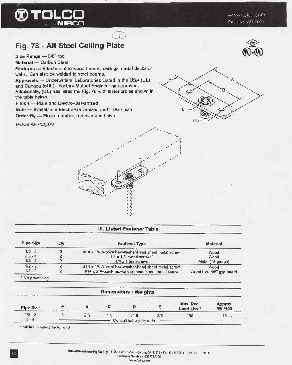
97 13-97
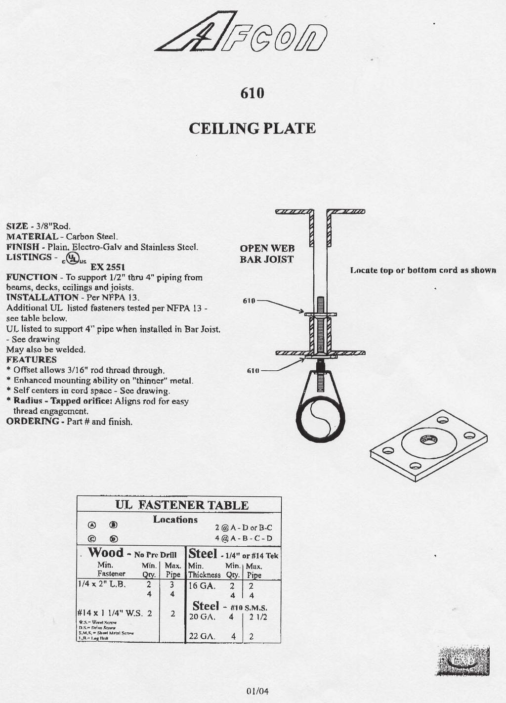
98 13-98
99 the finished ceiling. The submitter is encouraged to provide substantiation supporting the proposed changes. NUMBER ELIGIBLE TO VOTE: 26 BALLOT RESULTS: Affirmative: 23 BALLOT NOT RETURNED: 3 BIGGINS, KING, MADDEN Log #207 AUT-HBS Final Action: Accept in Principle ( ) SUBMITTER: James Everitt, Western Regional Fire Code Development Committee RECOMMENDATION: Revise to read: The unsupported length between the end sprinkler to a drop nipple supplying a pendent sprinkler and the last hanger on the branch line shall not be greater than 12 in. (305 mm) for steel pipe or 6 in. (152 mm) for copper pipe. SUBSTANTIATION: As written contradicts for pendent sprinklers. The hanger within 1 foot of a drop is intended when sprinklers are installed below a suspended ceiling and subject to damage or movement from vertical thrust. The reference to any, end sprinkler in a pendent position should be removed or clarified as intended to apply when sprinklers are installed below a suspended ceiling. An example of a pendent sprinklers without a hanger within 12 would be almost any ESFR pendent sprinkler. It is doubtful that it is the intent of to require a hanger within 12 of every pendent sprinkler. in Principle See Proposal (Log# 649) COMMITTEE STATEMENT: See Proposal (Log# 649) NUMBER ELIGIBLE TO VOTE: 26 BALLOT RESULTS: Affirmative: 23 BALLOT NOT RETURNED: 3 BIGGINS, KING, MADDEN Log #438 AUT-HBS Final Action: Accept in Principle ( ) SUBMITTER: Kraig Kirschner, AFCON RECOMMENDATION: Add second sentence after existing...copper tube. Piping with less wall strength is not allowed to have an unsupported armover. SUBSTANTIATION: Manufacturers of flexible drops are promoting their use as unsupported armovers. in Principle Insert a new Section and A as follows: * Flexible Sprinkler Hose Fittings. Listed flexible sprinkler hose fittings and its anchoring components, intended for use in installations connecting the sprinkler system piping to sprinklers shall be installed in accordance with the requirements of the listing including any installation instructions. A Examples of areas of use include clean rooms, suspended ceilings, and exhaust ducts. COMMITTEE STATEMENT: The committee has concerns with equivalency as a hanger and the relationship and quality control of the support of the ceiling grid. The committee seeks additional information from manufacturers and listing agencies to document the equivalency of these products meeting or exceeding the current level of hanging requirements of NFPA 13 in accordance with the requirements of the equivalency and new technology requirements of NFPA 13. NUMBER ELIGIBLE TO VOTE: 26 BALLOT RESULTS: Affirmative: 23 BALLOT NOT RETURNED: 3 BIGGINS, KING, MADDEN Log #67 AUT-HBS Final Action: Reject ( , ) SUBMITTER: Larry Keeping, Vipond Automatic Sprinkler Company Limited RECOMMENDATION: Revise to read: The cumulative sprinkler drop, sprig-up sprig shall not exceed Revise to read: Sprig-ups Sprigs 4 ft (1.2 m) or longer SUBSTANTIATION: Editorial, to use the word sprig, which is the common term used in the industry and which is used in the standard slightly more often then sprig-up is used. COMMITTEE STATEMENT: Sprig up more accurately describes the intent and is a common industry term and is defined in Chapter 3. NUMBER ELIGIBLE TO VOTE: 26 BALLOT RESULTS: Affirmative: 23 BALLOT NOT RETURNED: 3 BIGGINS, KING, MADDEN Log #650 AUT-HBS Final Action: Accept in Principle ( ) SUBMITTER: Victoria B. Valentine, National Fire Sprinkler Association RECOMMENDATION: Add a new section as follows: A hanger shall be provided on every armover for steel pipe where the horizontal length exceeds 24 inches or where the total length of the armover and drop exceeds 6 ft. A hanger shall be provided on every armover for copper tube where the horizontal length exceeds 1 ft or where the total length of the armover and drop exceeds 6 ft. SUBSTANTIATION: Right now, if an armover on steel pipe is less than 24 inches horizontally, and then drops down 50 ft, it is not required to have a hanger. Yet the force on the fitting would break the piping apart. Some vertical distance needs to be established that would warrant the installation of a hanger on the horizontal part of the armover to take up the load of the drop to the sprinkler. Guidance is also needed for copper tube. This proposal was developed by the NFSA Engineering and Standards Committee. in Principle COMMITTEE STATEMENT: The committee agreed with the submitter, but wanted to develop more detailed requirements based upon actual field conditions. An arm over task group has been formed to provided comments and specific language to address this issue. NUMBER ELIGIBLE TO VOTE: 26 BALLOT RESULTS: Affirmative: 22 Negative: 1 BALLOT NOT RETURNED: 3 BIGGINS, KING, MADDEN EXPLANATION OF NEGATIVE: THACKER: Fire sprinkler drops have been installed without a length limit and there have not been any bad consequences. The 6 ft-0 in. limitation in drop length is ridiculous causing undue cost to the consumer Log #CP20 AUT-HBS Final Action: Accept ( ) SUBMITTER: Technical Committee on Hanging and Bracing of Water-Based Fire Protection Systems RECOMMENDATION: Reword section as follows: Unless the requirements of , , , or are met, hangers for mains shall be in accordance with 9.2.2, between each branch line, or on each section of pipe, whichever is the lesser dimension SUBSTANTIATION: Currently it is not clear if the hanger requirement of one hanger for each section of pipe applies only to branch lines or to all piping. These proposed changes are intended to clarify the hanger requirements for mains. NUMBER ELIGIBLE TO VOTE: 26 BALLOT RESULTS: Affirmative: 23 BALLOT NOT RETURNED: 3 BIGGINS, KING, MADDEN Log #139 AUT-HBS Final Action: Reject (9.2.5) TCC ACTION: The Technical Correlating Committee directs that AUT-SSI review this log for any correlation issues. SUBMITTER: David M. Schwartz, axiem RECOMMENDATION: Add new text as follows: Support of Risers Risers shall be supported by pipe clamps or by hangers located on the horizontal connections within 24 in. of the centerline of the riser Pipe clamps supporting risers by means of set screws shall not be used Multistory Buildings In multistory buildings, riser supports shall be provided at the lowest level, at each alternate level above, above and below offsets, and at the top of the riser Supports above the lowest level shall also restrain the pipe to prevent movement by an upward thrust where flexible fittings are used Where risers are supported from the ground, the ground support shall constitute the first level of riser support Where risers are offset or do not rise from the ground, the first ceiling level above the offset shall constitute the first level of riser support Distance between supports for risers shall not exceed 25 ft (7.6 m) Sprig-ups Branch lines with multiple sprig-ups in excess of 3 ft 0 in. (1 m) and installed with standard grooved type pipe couplings or similar fittings shall be secured to prevent rotation from one of the following methods: 1) The branch line is to be braced between every set of grooved type pipe couplings or similar fittings. 2) Every third sprig-up is to be braced to a structural member.
100 3) The use of grooved pipe couplings that restrict rotation. COMMENT ON AFFIRMATIVE SUBSTANTIATION: I have witnessed three (3) separate cases where branch GILLENGERTEN: I agree with the general approach, for cases where lines, installed with grooved pipe couplings and long 1 in. sprig-ups, have prescriptive spacing requirements are enforced. The committee should consider rotated over from vibration through the structural members the hangers were criteria for conditions where the reference standard for seismic design (ASCE attached to. 7-05, for example) requires a more rigorous approach. Non-metallic pipe may With the use of lubricant for the installation of the rubber gaskets of standard already be subject to penalties in lateral design, due to reduction in the Rp grooved pipe couplings, the pipe will tend to rotate easily. If multiple long 1 in. factor. In this case, a further reduction in brace spacing may be unwarranted. sprig-ups are not installed perfectly vertical, the offset weight would provide the force needed to roll over the branch line. COMMITTEE STATEMENT: The committee does not believe that bracing is an appropriate level of protection for this application. The committee does not believe that the problem is caused by the hanging of the pipe, but by the joining of the pipe. Additionally, there is no technical support to provide the additional requirements. The submitter is encouraged to submit supporting material to address any proposed requirements. Additionally the hanging and bracing committee requests that the installation committee review this proposal for possible issues with pipe joining methods. NUMBER ELIGIBLE TO VOTE: 26 BALLOT RESULTS: Affirmative: 23 BALLOT NOT RETURNED: 3 BIGGINS, KING, MADDEN Log #173 AUT-HBS Final Action: Reject ( ) SUBMITTER: David Stringfield, University of Minnesota RECOMMENDATION: Revise text to read: Arrangement of... or operational accident that occurs away from the fire pump equipment that interrupts... SUBSTANTIATION: The revision is to clarify that near the transfer switch it is extremely expensive to totally separate the power sources. COMMITTEE STATEMENT: This proposal appears to propose modification to NFPA 20 which is not the responsibility of this Technical Committee. NUMBER ELIGIBLE TO VOTE: 26 BALLOT RESULTS: Affirmative: 23 BALLOT NOT RETURNED: 3 BIGGINS, KING, MADDEN Log #CP200 AUT-HBS Final Action: Accept (New and A.9.2.7) SUBMITTER: Technical Committee on Hanging and Bracing of Water-Based Fire Protection Systems RECOMMENDATION: 9.2.7* Support of Pipe. Where pipe supports are utilized they shall be approved. A Examples include headers and horizontal runs of pipe that need support from the floor. SUBSTANTIATION: The committee wanted to address situations where piping required support, but was not hung from the building structure. It is the intent of the committee that the pipe supports only be approved and not be listed. NUMBER ELIGIBLE TO VOTE: 26 BALLOT RESULTS: Affirmative: 22 Negative: 1 BALLOT NOT RETURNED: 3 BIGGINS, KING, MADDEN EXPLANATION OF NEGATIVE: THACKER: The word approved should be changed to reference section , substituting the word support for the word hanger Log #CP202 AUT-HBS Final Action: Accept ( ) SUBMITTER: Technical Committee on Hanging and Bracing of Water-Based Fire Protection Systems RECOMMENDATION: Non-Metallic Pipe. Non-metallic pipe shall be braced and restrained in accordance with the requirements of NFPA 13, where the allowable spacing shall be reduced by 50 percent or shall be installed in accordance with the pipe listing requirements. SUBSTANTIATION: The reduced bracing and restraint spacing requirements for non-metallic sprinkler pipe are typical in ASHRAE manuals and MSS-SP 127. These reduced spacings are an attempt to develop requirements for nonmetallic pipe. Manufacturers are encouraged to submit comments to NFPA 13 which provide specific recommendations on the proper bracing and restraint of non-metallic pipe. NUMBER ELIGIBLE TO VOTE: 26 BALLOT RESULTS: Affirmative: 23 BALLOT NOT RETURNED: 3 BIGGINS, KING, MADDEN Log #766 AUT-HBS Final Action: Accept in Principle (Figure 9.3.1(a) and (b)) SUBMITTER: J. Scott Mitchell, American Fire Sprinkler Association RECOMMENDATION: Delete these figures from the annex. SUBSTANTIATION: While these figures provide general information about the seismic activity throughout the U.S., the confusion they create justifies their deletion. Some look at the figures and assume that systems installed in Zone 0 do not require earthquake protection. Actually, they provide information that is useless in both determining whether earthquake protection is required and in the design, layout, or installation of earthquake protection. in Principle Accept the deletion of the figures. Additionally, delete the last sentence from Section A which includes the Figure references. COMMITTEE STATEMENT: The committee agreed with the submitter but wanted to also delete the appropriate reference text within the annex. NUMBER ELIGIBLE TO VOTE: 26 BALLOT RESULTS: Affirmative: 23 BALLOT NOT RETURNED: 3 BIGGINS, KING, MADDEN Log #492 AUT-HBS Final Action: Accept in Principle (9.3.2) SUBMITTER: Daniel C. Duggan, Fire Sprinkler Design RECOMMENDATION: Revise as follows: 9.3.2* Couplings Displacement SUBSTANTIATION: It has been asserted by some that technically NFPA 13 could not be used to satisfy the seismic design requirements of ASCE 7-02, and therefore, could not satisfy the requirements of either the NFPA 5000 code, the NEHRP Standard or the International Building Code. The reasoning behind this assertion is the contention that NFPA 13 requirements do not satisfy the displacement requirements of these Codes and Standards and the Code and Standards require satisfaction of both the force and displacement requirements. This contention is incorrect and this proposal would change the title of this section to specifically reference displacement to put the issue to rest. The displacement requirements of these Codes and Standards relate entirely to allowances for story drift, which is provided for in NFA 13 with the requirement for flexible grooved couplings above and below each floor. The amount of deflection provided by these flexible couplings is 2 or more depending on the pipe size, which provides 8 in. or more of deflection in 20 ft. The maximum story drift permitted by ASCE 7-02 by Table is 2 1/2 percent of the story height. This criteria would result in 6 in. of deflection. Further, of ASCE 7-02 indicates that the maximum story drift shall be taken as 1 percent of the story height. In either event, NFPA 13 satisfies the displacement requirements of these Codes and Standards. in Principle Add a new section as follows: Displacement due to story drift is addressed in Sections through COMMITTEE STATEMENT: The proposed new section addresses the submitter concerns. NUMBER ELIGIBLE TO VOTE: 26 BALLOT RESULTS: Affirmative: 22 Negative: 1 BALLOT NOT RETURNED: 3 BIGGINS, KING, MADDEN EXPLANATION OF NEGATIVE: GILLENGERTEN: The seismic design provisions of ASCE 7-02 require more than just a check for story drift. The last paragraph of ASCE 7-02, Section states: Seismic effects that shall be considered in the design of a piping system include the dynamic effects of the piping system, its contents, and, when appropriate, its supports. The interaction between the piping system and the supporting structures, including other mechanical and electrical equipment shall also be considered. Interaction between the piping system and other portions of the structure and non-structural components includes impact of the pipe on adjacent elements, which will require an estimate of pipe displacement. This has been further expanded in ASCE General Design Requirements Consequential Damage. The functional and physical interrelationship of components, their supports and their effect on each other shall be considered
101 so that the failure of an essential or nonessential architectural, mechanical, or electrical component shall not cause the failure of an essential architectural, mechanical, or electrical component Flexibility. The design and evaluation of components, their supports, Log #761 AUT-HBS Final Action: Accept in Principle and their attachments shall consider their flexibility as well as their strength. ( (5)) Therefore, simply complying with story drift requirements is not sufficient to meet the general design requirements of ASCE 7. In fact, many of the failures SUBMITTER: J. Scott Mitchell, American Fire Sprinkler Association of sprinkler systems have been the result of adverse interactions between the sprinkler system and other components in the structure (for example hard ceiling systems). These failures are well documented Log #653 AUT-HBS Final Action: Accept in Principle ( (2)) SUBMITTER: Victoria B. Valentine, National Fire Sprinkler Association RECOMMENDATION: Revise text as follows: (2)* Within 12 in. (305 mm) above and within 24 in. (610 mm) below the floor in multistory buildings. When the flexible coupling below the floor is above the tie-in main to the main supplying that floor, the tie-in main shall have a vertical riser and one or more a flexible coupling s shall be provided on the vertical portion of the tie-in piping. When the flexible coupling below the floor is below the tie-in main and when the main drops below that flexible coupling, the tie-in main shall have a vertical riser and one or more flexible couplings shall be provided on the vertical portion of the tie-in piping. SUBSTANTIATION: The riser is needed to allow the system to accommodate the potential horizontal movement of the main riser in coordination with the rigid bracing to the ceiling assembly. in Principle Reword Section (2) as follows: (2)* Within 12 in. (305 mm) above and within 24 in. (610 mm) below the floor in multistory buildings. When the flexible coupling below the floor is above the tie-in main to the main supplying that floor, a flexible coupling shall be provided either on the horizontal or vertical portion of the tie-in piping. COMMITTEE STATEMENT: The committee agreed with the submitter, but wanted to ensure that flexibility would be provided where the tie-in main is connected below the flexible coupling. NUMBER ELIGIBLE TO VOTE: 26 BALLOT RESULTS: Affirmative: 23 BALLOT NOT RETURNED: 3 BIGGINS, KING, MADDEN RECOMMENDATION: Revise the text as follows: Within 24 in. of the top of and within 24 above the uppermost drop support attachment fo r bottom of drops to hose lines, rack sprinklers, and mezzanines, regardless of pipe size. SUBSTANTIATION: Most drops have multiple support attachments securing the drop to the building structure or rack. When the drop is secured to the structure or rack, it will move with the structural member (column) or rack. Flexible couplings installed below the uppermost attachment is of no value. By installing both flexible couplings between the top of the drop and the uppermost drop attachment, independent movement of the rack, mezzanine, column, and the attached drop is maximized. in Principle Delete current (5). Add a new as follows: * Flexible Couplings for Drops. Flexible Couplings for drops to hose lines, rack sprinklers, and mezzanines, shall be installed regardless of pipe sizes as follows: A. Within 24 in. of the top of the drop. B. Within 24 in. above the uppermost drop support attachment, where drop supports are provided to the structure, rack or mezzanine. C. Within 24 in. above the bottom of the drop where no additional drop support is provided. (See Figure A below.) 24 in. [Section (A)] Flexible couplings In-rack sprinkler drops Flexible couplings 24 in. [Section (C)] 24 in. [Section (B)] Drop supports Figure A Flexible Couplings for Drops
102 COMMITTEE STATEMENT: The committee agreed with the submitter, but side of the penetration. 13: also supports this position by not requiring wanted to ensure the couplings would be located at the proper locations clearance where nonmetallic pipe has been demonstrated to have inherent regardless of the suppport of the drops. flexibility equal to or greater than the minimum provided by flexible couplings NUMBER ELIGIBLE TO VOTE: 26 located within 1 of each side of the penetration. When no clearance is provided BALLOT RESULTS: Affirmative: 23 and the penetration is tight around the circumference of the pipe, differential BALLOT NOT RETURNED: 3 BIGGINS, KING, MADDEN movement will not result in pipe damage if the pipe is flexible. Piping 2 or smaller is pliable enough that clearance around the pipe at penetrations is not necessary Log #507 AUT-HBS Final Action: Accept in Principle (9.3.3 and A.9.3.3) SUBMITTER: Russell P. Fleming, National Fire Sprinkler Association RECOMMENDATION: Revise text to read as follows: Seismic Separation Assembly. A n approved seismic separation assembly with flexible fittings shall be installed where sprinkler piping, regardless of size, crosses building seismic separation joints above ground level. Seismic separation assemblies shall consist of flexible fittings or flexible piping so as to allow movement sufficient to accommodate closing of the separation, opening of the separation to twice its normal size, and movement relative to the separation in the other two dimensions an amount equal to the separation distance. Also, add a new Figure A.9.3.3(b) as Seismic separation assembly incorporating flexible piping. SUBSTANTIATION: There is a need to define the desired movement of a seismic separation assembly within the text of the standard - it currently is contained only indirectly within an annex figure. The wording of the text should also recognize that products are available in the marketplace that can accommodate the desired movement through the use of flexible piping. An illustration of such a product would be helpful to the user of the standard. in Principle Accept the proposed language and reword Section as follows: 9.3.3* Seismic Separation Assembly An approved seismic separation assembly shall be installed where sprinkler piping, regardless of size, crosses building seismic separation joints above ground level Seismic separation assemblies shall consist of flexible fittings or flexible piping so as to allow movement sufficient to accommodate closing of the separation, opening of the separation to twice its normal size, and movement relative to the separation in the other two dimensions in an amount equal to the separation distance. Also, renumber Figure A as Figure A.9.3.3(a) and add a new Figure A.9.3.3(b) as follows: Figure A (b) Seismic Separation Assembly Incorporating Flexible Piping Additionally see (Log #201) for a sample figure. COMMITTEE STATEMENT: The committee agrees with the submitter but wanted to add the proposed figure from Proposal (Log # 201) as the sample figure for the annex. NUMBER ELIGIBLE TO VOTE: 26 BALLOT RESULTS: Affirmative: 23 BALLOT NOT RETURNED: 3 BIGGINS, KING, MADDEN Log #762 AUT-HBS Final Action: Reject ( ) SUBMITTER: J. Scott Mitchell, American Fire Sprinkler Association RECOMMENDATION: Revise the text as follows: Clearance shall be provided around all piping 2-1/2 in. or larger extending through SUBSTANTIATION: This follows the same philosophy established by , where listed flexible couplings are only required for piping 2-1/2 in. or larger. A says Piping 2 in. or smaller in size is pliable enough so that flexible couplings are not usually necessary. If it is pliable enough not to require flexible couplings, it is pliable enough to penetrate through walls, floors, platforms, and foundations. COMMITTEE STATEMENT: The intent of the committee is that clearance be provided for pipe of all sizes to provide not only flexibility, but to prevent damage during movement. NUMBER ELIGIBLE TO VOTE: 26 BALLOT RESULTS: Affirmative: 22 Negative: 1 BALLOT NOT RETURNED: 3 BIGGINS, KING, MADDEN EXPLANATION OF NEGATIVE: MITCHELL: Seismic events damage sprinkler system piping. Increasing flexibility between major parts of the system, such as using listed flexible couplings and providing clearances at walls and floors helps prevent this damage. 13: requires listed flexible couplings, but only on 2-1/2 or larger piping. As indicated in 13:A.9.3.2, piping 2 or smaller is pliable enough so that flexible couplings are not usually necessary. However, 13: requires clearance around all piping regardless of size. If piping 2 or smaller is inherently flexible enough to not require flexible couplings, then it is inherently flexible enough not to require clearance. 13: supports this position by not requiring clearance when flexible couplings are located within 1 of each Log #654 AUT-HBS Final Action: Accept ( ) SUBMITTER: Victoria B. Valentine, National Fire Sprinkler Association RECOMMENDATION: Delete the last sentence of Section Unless the requirements of , , or are met, where pipe passes through holes in platforms, foundations,walls, or floors, the holes shall be sized such that the diameter of the holes is nominally 2 in. (51 mm) larger than the pipe for 1-in. (25.4 mm) nominal to 3 1/2 in. (89 mm) nominal and 4- in. (102 mm) larger than the pipe for pipe 4-in. (102 mm) nominal and larger. Clearance from structural members not penetrated or used collectively or independently to support the pipe shall be at least 2 in. (51 mm). SUBSTANTIATION: The last sentence of this section is Section and is therefore repetitive. NUMBER ELIGIBLE TO VOTE: 26 BALLOT RESULTS: Affirmative: 23 BALLOT NOT RETURNED: 3 BIGGINS, KING, MADDEN Log #769 AUT-HBS Final Action: Accept ( ) SUBMITTER: Randy R. Nelson, VFS Fire Protection Services / Rep. American Fire Sprinkler Association RECOMMENDATION: Revise the text as follows: The structural components to which bracing is attached shall be determined to be capable of carrying resisting the added applied seismic loads. SUBSTANTIATION: The term carrying implies a vertical load only as with hangers. The proposed terminology more accurately describes the dynamics of the arrangement. NUMBER ELIGIBLE TO VOTE: 26 BALLOT RESULTS: Affirmative: 23 BALLOT NOT RETURNED: 3 BIGGINS, KING, MADDEN Log #491 AUT-HBS Final Action: Accept in Principle ( ) SUBMITTER: Daniel C. Duggan, Fire Sprinkler Design RECOMMENDATION: Revise as follows: The distance between the last brace and the end of the pipe shall not exceed 20 ft 5 ft (6.1 m) (1.5 m). SUBSTANTIATION: Prior to the 1996 Edition of NFPA 13 a lateral sway brace was required on the last length of pipe at the end of feed and crossmains. In earlier days the last length of crossmain would have been sch. 40 threaded pipe with screwed fittings and most often about 10 or 12 ft in length, which would have resulted in the last brace being about 5 ft from the end. In the 1996 change cycle a change in this wording was adopted that would permit this lateral brace to be as much as 20 ft from the end of the main. This change was recommended because the use of full lengths of piping had become so common place in today s installations. The 20 ft limitation was selected because it is one half of the maximum allowable lateral brace spacing of 40 ft. Unfortunately, the 20 ft limitation will result in the last lateral brace being within 1 ft to 4 ft of a grooved coupling with the earthqake load on the last 20 ft of crossmain with branch lines cantilevered beyond the brace and allowed to move freely, which would also apply extraordinary prying action on the grooved coupling at the brace. Changing this limitation to 5 ft would ameliorate these concerns and have little or no impact on the cost of compliance. in Principle Accept proposal change but, change 5 to 6 feet. Reword Section as follows: The distance between that last brace and the end of the pipe shall not exceed 6 ft (1.8 m). COMMITTEE STATEMENT: The committee agrees with submitter, but wanted to harmonize NFPA 13 requirements with the FM requirements. NUMBER ELIGIBLE TO VOTE: 26 BALLOT RESULTS: Affirmative: 22 Negative: 1 BALLOT NOT RETURNED: 3 BIGGINS, KING, MADDEN
103 EXPLANATION OF NEGATIVE: VALENTINE: The action taken by the Committee in this proposal appears extreme. The new 6 ft requirement for maximum distance of a lateral brace from the end of the line is very restrictive. There has been no field evidence that has shown significant damage due to the current arrangement that is in the standard. The other difficulty that this proposal creates is reasonable locations to attach the brace. More stability can be achieved by attaching the brace to larger structural members than smaller ones that will be towards the end of a main Log #655 AUT-HBS Final Action: Reject ( ) SUBMITTER: Victoria B. Valentine, National Fire Sprinkler Association RECOMMENDATION: Bring back Note that the TIA took this section away. SUBSTANTIATION: It may be better to have a brace 50 ft apart at the major structural members that can handle the load rather than try and fit some sort of trapeze brace in between structural members. Worse yet would be to attach braces closer together to smaller structural members that cannot handle the load. If the braces 50 ft apart can handle the load of the sprinkler system, they should be permitted. This proposal was developed by the NFSA Engineering and Standards Committee. COMMITTEE STATEMENT: The deletion of the section is correct since it is inappropriate to generically indicate that 50 ft spacing is acceptable without proper evaluation. The committee is aware of many applications where the 50 ft spacing limits would be incorrect and would exceed acceptable design limits. NUMBER ELIGIBLE TO VOTE: 26 BALLOT RESULTS: Affirmative: 22 Negative: 1 BALLOT NOT RETURNED: 3 BIGGINS, KING, MADDEN EXPLANATION OF NEGATIVE: THACKER: The 50 ft- 0 in. earthquake brace spacing was added to NFPA 13 so bracing would provide an exception when 40 ft- 0 in. doesn t work due to the building elements being spaced up to 50 ft- 0 in. on center. Try bracing to a Z purlin greater than 40 ft- 0 in. long. When 50 ft- 0 in. is utilized, the earthquake brace and its components are design to reflect the 50 ft- 0 in. loading. It has worked, is working and was performed well during the Northridge quake Log #490 AUT-HBS Final Action: Accept in Principle ( ) SUBMITTER: Daniel C. Duggan, Fire Sprinkler Design RECOMMENDATION: Revise as follows: Where flexible couplings are installed on mains other than as required in 9.3.2, a lateral brace shall be provided within 24 in. (610 mm) of every other coupling, including couplings at grooved fittings, but not more than 40 ft (12.2 m) on center. SUBSTANTIATION: The present wording is unclear as to whether or not additional lateral bracing is required at grooved fittings or if every other one of those grooved couplings are counted, when flexible grooved couplings are used. For example, on a grooved cross there would be four grooved couplings and a single lateral brace could be located within 24 in. of all of them. in Principle Revise as follows: Where flexible couplings are installed on mains other than as required in 9.3.2, a lateral brace shall be provided within 24 in. (610 mm) of every other flexible coupling, including flexible couplings at grooved fittings, but not more than 40 ft (12.2 m) on center. COMMITTEE STATEMENT: The committee agreed with the submitter but wanted to further clarify the application of flexible couplings NUMBER ELIGIBLE TO VOTE: 26 BALLOT RESULTS: Affirmative: 23 BALLOT NOT RETURNED: 3 BIGGINS, KING, MADDEN COMMENT ON AFFIRMATIVE GILLENGERTEN: I don t have a problem with clarifying and enhancing the prescriptive brace spacing requirements, but, as shown in the analysis done by BSSC TS8 members on sprinkler brace spacing and stresses (attached to the minutes), a reduction of brace spacing in higher seismic zones needs to be considered Log #799 AUT-HBS Final Action: Reject ( ) SUBMITTER: Charles Bamford, Bamford Inc. / Rep. AFSA RECOMMENDATION: Revise the text as follows: The requirements of shall not apply to pipes individually supported by rods less than 6 in. long measured between the top of the pipe and the point of attachment to the building structure, where the hanger rod is screwed down to the top of the pipe or where a surge restraint clip is installed. SUBSTANTIATION: This adds stabilization to pipe that is not provided with sway bracing. COMMITTEE STATEMENT: The committee rejects the proposed changes since the current arrangement in NFPA 13 meets the required criteria. Additionally the proposed new requirements have not been substaintiated. NUMBER ELIGIBLE TO VOTE: 26 BALLOT RESULTS: Affirmative: 23 BALLOT NOT RETURNED: 3 BIGGINS, KING, MADDEN Log #862 AUT-HBS Final Action: Reject ( ) SUBMITTER: Kraig Kirschner, AFCON RECOMMENDATION: Delete in its entirety. SUBSTANTIATION: Does not address pipe size, load per ZOI or horizontal force factor. This blurs the difference between hangers and Sway Braces and even restraint. COMMITTEE STATEMENT: The committee rejects the proposed changes, but asks the submitter to document cases/scenarios where the use of the 6 in. exception is inappropriate and would result in unacceptable conditions. NUMBER ELIGIBLE TO VOTE: 26 BALLOT RESULTS: Affirmative: 23 BALLOT NOT RETURNED: 3 BIGGINS, KING, MADDEN COMMENT ON AFFIRMATIVE KIRSCHNER: The six in. rod rule predates zone of influence load calculations in NFPA 13. In spite of the dampening effect of short hanger assemblies, I have problems with the inclusiveness of this rule. We are saying that this hanger, that evidences none of the component criteria of the sway brace, including the fastener, will always work. Fasteners for sway braces in wood or concrete are becoming very problematic. We also allow this exemption regardless of the following: Pipe size - could be an eight in. feed main The ZOI due to additive line load could exceed the cross main load Horizontal force factors could be very high as in zone D, E, or F If upper hanger component is rigid in nature are we bending the hanger rod In view of the above I have trouble supporting the six in. rod rule exception Log #863 AUT-HBS Final Action: Reject ( ) SUBMITTER: Kraig Kirschner, AFCON RECOMMENDATION: Plssibly delete or alter. SUBSTANTIATION: Mixing hanger methodology and sway brace methodology is problematic. If allows 0 degrees if less than 6 in. then why not this section. COMMITTEE STATEMENT: The committee rejects the proposed changes. The submitter provided no specific recommendations. The submitter is encouraged to submit specific changes with appropriate substantiation. NUMBER ELIGIBLE TO VOTE: 26 BALLOT RESULTS: Affirmative: 23 BALLOT NOT RETURNED: 3 BIGGINS, KING, MADDEN COMMENT ON AFFIRMATIVE KIRSCHNER: When u-hooks are sway braces they must meet fastener, angle of orientation and material criteria. Revising will clarify our intent. Reword to read: The requirements of shall not apply where U-type hooks of the wraparound type or those U-type hooks arranged to keep the pipe tight to the underside of the structural element shall be permitted to be used to satisfy the requirements for lateral sway bracing, provided the legs are bent out at least 30 degrees from the vertical and the maximum length of each leg and the rod size satisfies the conditions of Table (a), Table (b), and Table
104 (c). they satisfy the conditions of and Wraparound u-hooks violate because they are not tight. They can t be sway braces but are acceptable as restraint. Revising (2) will clarify our intent. Reword to read: (2) A wraparound U-hook satisfying the requirements of with legs bent out at least 30 degrees from the vertical per Table (c) Log #763 AUT-HBS Final Action: Accept in Principle ( ) SUBMITTER: J. Scott Mitchell, American Fire Sprinkler Association RECOMMENDATION: Add new text as follows: The requirements of shall not apply to 2-1/2 in. starter pieces. SUBSTANTIATION: As the current requirements are given, a lateral brace would be required on short starter pieces if they are 2-1/2 in. in diameter. in Principle Add new text as follows to the end of current Section : Lateral sway bracing spaced at a maximum interval of 40 ft (12.2 m) on center shall be provided on all feed and cross mains regardless of size and all branch lines and other piping with a diameter of 2-1/2 in. (63.5 mm) and larger. The requirements of shall not apply to 2-1/2 in. starter pieces that do not exceed 12 ft in length. COMMITTEE STATEMENT: The committee agreed with the submitter but wanted to establish a limit to the length of the starter piece. NUMBER ELIGIBLE TO VOTE: 26 BALLOT RESULTS: Affirmative: 23 BALLOT NOT RETURNED: 3 BIGGINS, KING, MADDEN COMMENT ON AFFIRMATIVE GILLENGERTEN: I don t have a problem with clarifying and enhancing the prescriptive brace spacing requirements, but, as shown in the analysis done by BSSC TS8 members on sprinkler brace spacing and stresses (attached to the minutes), a reduction of brace spacing in higher seismic zones needs to be considered Log #656 AUT-HBS Final Action: Reject ( (New) ) SUBMITTER: Victoria B. Valentine, National Fire Sprinkler Association RECOMMENDATION: Add a new section as follows: Holes through solid structural members shall be permitted to serve as lateral braces provided such holes are permitted by applicable building codes and the spacing and bracing provisions of this standard are satisfied. In order to meet this provision, the hole around the pipe shall be no more than 1/2 inch larger than the pipe. SUBSTANTIATION: Section allows holes in structural members to serve as support (hanger) for the piping. Similarly, a hole in a structural member will prevent piping from moving laterally during an earthquake. The objective of getting the sprinkler system moving with the ceiling can be accomplished by this method of installation without additional lateral braces as long as the structure can take the load and the members are close enough together. This proposal was developed by the NFSA Engineering and Standards Committee. COMMITTEE STATEMENT: The committee has concerns with quality control of the holes. Additionally, the proposed change violates the requirements , which requires that the sway bracing be tight. The committee has additional concerns with the pipe moving around within the opening and causing damage to the piping. NUMBER ELIGIBLE TO VOTE: 26 BALLOT RESULTS: Affirmative: 22 Negative: 1 BALLOT NOT RETURNED: 3 BIGGINS, KING, MADDEN EXPLANATION OF NEGATIVE: VALENTINE: Holes in structural members are sufficient to hang sprinkler piping, which is a constant gravitational load. With the knowledge that the floor/ceiling assembly moves as a unit, it should be a reasonable assumption that the piping would be sufficiently braced as well in this type of arrangement. The Committee notes that this would not allow for tight fitting of the holes to the piping, but it is well accepted that some freedom of movement is acceptable as demonstrated by the 6 ft hanger rod exception to lateral bracing. For other mechanical systems, it is standard practice to waive the brace requirements for hangers that have up to 12 in. rods, allowing even more movement Log #657 AUT-HBS Final Action: Accept ( ) SUBMITTER: Victoria B. Valentine, National Fire Sprinkler Association RECOMMENDATION: Revise text as follows: Section should read, Longitudinal braces shall be allowed to act as lateral braces if they are within 24 in. (610 mm) of the centerline of the piping braced laterally. SUBSTANTIATION: The language of this section should be parallel to Section for lateral bracing. Parallel language allows the user to more easily understand the intent of the standard. NUMBER ELIGIBLE TO VOTE: 26 BALLOT RESULTS: Affirmative: 23 BALLOT NOT RETURNED: 3 BIGGINS, KING, MADDEN Log #39 AUT-HBS Final Action: Accept in Principle ( , A and and ) SUBMITTER: Antonio C. M. Braga, Factory Mutual Research Corp. RECOMMENDATION: 1. Reword Sections , , A , and to read as follows: * Horizontal Seismic Loads The horizontal seismic load for the braces shall be determined as required by the authority having jurisdiction. The weight of the system being braced (Wp) shall be taken as 1.15 times the weight of the water-filled piping. [See A ] A The several factors used in the computation of the horizontal seismic load should be available from the project architect or structural engineer. Sprinkler systems are emergency systems and as such should be designed for an Importance Factor (Ip) of 1.5. Seismic load equations allow the reduction of the seismic force by a Component Response Modification Factor (Rp), that reflects the ductility of the system; systems where braced piping are primarily joined by threaded fittings should be considered less ductile than systems where braced piping are joined by welded or mechanical type fittings. While research continues in understanding the performance of sprinkler piping under seismic loads, the good performance of properly braced sprinkler piping in past earthquakes suggests that properly braced systems perform with high ductility, which currently relates to an Rp factor of Where the authority having jurisdiction does not specify the horizontal seismic load, the horizontal seismic force acting on the braces shall be determined based on a horizontal force of Fp= 0.5 Wp, where Fp is the horizontal force factor and Wp is 1.15 times the weight of the water filled piping Where the horizontal seismic loads used exceed 0.5 Wp and the brace angle is less than 45 degrees from vertical or where the horizontal seismic load exceeds 1.0 Wp and the brace angle is less than 60 degrees from vertical, the braces shall be arranged to resist the net vertical reaction produced by the horizontal load. 2. Replace Figure as shown on the following page and its associated Tables and Modify Section A to read as follows:
105 Figure
106 13-L
107 13-L
108 A Current fasteners for anchoring to concrete are referred to as post installed anchors. There are several types of post installed anchors that include expansion anchors, chemical or adhesive anchors and undercut anchors. The criteria in Tables (a), (b) and (c) are based on the use of a wedge expansion anchors and undercut anchors. Use of other anchors in concrete should be in accordance with the listing provisions of the anchor. Anchorage are expected for piping with diameters larger than 2.5 inches. This analysis provides the first indications that for the average spectrum of roof motions the deflection value is consistent with the minimum clearance requirements for sprinkler piping. While additional work is needed, the results of this analysis are considered conservative as the analysis assumed that no pipe hangers were provided between braces designs are usable under ASD methods. Values in tables (a), (b) and (c) are based on an 8 to 1 safety factor in tension and a 4 to 1 in shear for allowable loads. Wedge anchors are torque-controlled expansion anchors that are set by applying a torque to the anchors nut, which causes the anchor to rise while the wedge stays in place. This causes the wedge to be pulled onto a coned section of the anchor and presses the wedge against the wall of the hole. Undercut anchors may or may not be torque-controlled. Typically, the main hole is drilled, a special second drill bit is inserted into the hole and flare is drilled at the base of the main hole. Some anchors are self-drilling and do not require a second drill bit. The anchor is then inserted into the hole and when torque is applied the bottom of the anchor flares out into the flared hole and a With respect to wall stress, the analysis indicate that the average roof motions from the 1994 Northridge, CA earthquake would result is a mid-span bending stress of approximately 11.5 ksi in a 40-foot span of 2.5-inch water filled pipe. This stress level compares very favorably to the yield stress and allowable stresses for pipe steel, Per ASTM A53 and A135 the yield stress for steel is sy = 30 ksi (Grade A) and sy = 35 ksi (Grade B). Hence, the allowable stress is 60 ksi (Grade A) and 70 ksi (Grade B). The allowable stress for threaded pipe is 0.87sy = 26 ksi (Grade A) and 30 ksi (Grade B). Higher deflections and stresses were obtained for the envelop of roof motions; indicating the need for additional research in the area. mechanical lock is obtained. Consideration should be given with respect to the position near the edge of a slab and the spacing of anchors. Typically for full capacity in tables (a), (b), and (c) the edge distance should be 1-1/2 times the embedment and 3 times the embedment for spacing between anchors. 3. Modify section to read as follows, and add a new annex section A to read as follows, Lateral Sway Bracing * Lateral sway bracing shall be provided on all feed and cross mains regardless of size and all branch lines and other piping with a diameter of 21/2 in. (63.5 mm) and larger. Lateral brace assemblies in straight runs of pipe shall capable of resisting the anticipated seismic loads and spaced to a maximum interval not exceeding 40 ft (12.2 m) on center. The load capacity of the brace 4. Finally, NFPA 13 has industry-wide recognition as the standard for design and installation of sprinkler piping, including how the piping needs to be supported and braced. The seismic protection requirements of NFPA 13 should continue to be aligned with governing building codes and national standards covering non-structure components. These issues are of critical importance for the design and performance of the system and if these proposals are not implemented now, language addressing these issues is very likely to be introduced in other codes and standards, such as the NEHRP and ASCE 7. This would confusion in the industry and result in misinterpretations of NFPA 13 requirements. assembly shall be determined by the capacity of its weakest component. A A brace assembly includes the brace member, the attachment components to pipe and building and their fasteners. There are primarily two considerations in determining the spacing of lateral earthquake braces in straight runs of pipe: (1) Deflection, and (2) Stress. Both deflection and stress tend to increase with the spacing of the braces. The larger the mid-span deflection, the greater the chance of impact with adjacent structural/nonstructural components. The higher the stress in the pipe, the greater the chance of rupture in the pipe or coupling. For properly sized braces, the 40 ft maximum spacing between lateral braces in straight runs of pipe result in defections and stresses consistent with the minimum required clearances in this standard and modern building codes. In the longitudinal direction, there is no deflection consideration, but the pipe must transfer the load to the longitudinal In summary, this proposal is of an emergency nature since it will (1) allow new systems to be designed and installed based on updated fastener capacity information, (2) allow new systems to be designed for the seismic loads given by the applicable building code, and (3) avoid conflicting parallel requirements in other documents, codes and standards. in Principle Accept all changes from the TIA except modify Section as follows: * Lateral sway bracing shall be provided on all feed and cross mains regardless of size and all branch lines and other piping with a diameter of 2 1/2 in. (63.5 mm) and larger in accordance with Table The load capacity of the brace assembly shall be determined by the capacity of its weakest component. braces without inducing large axial stresses in the pipe and the couplings. 4. Delete Section Renumber Sections through as Sections through Table Maximum Lateral Brace Spacing Maximum Lateral Brace Spacing Seismic Design Category C Seismic Design Category SUBSTANTIATION: NOTE: This Proposal originates from Tentative Interim Amendment 02-1 issued by the Standards Council on July 17, Pipe Size Fp < 0.5 Wp D, E, F Technical Justification. 0.5 Wp Fp 1.6 Wp These proposed changes were developed by the NFPA 13 Hanging and Bracing Schedule 10 Schedule 40 Schedule Schedule 40 Committee special seismic committee in order to provide clarification and 10 alignment of current NFPA 13 requirements with respect to seismic loads, 1 in. 40 ft. 40 ft. 30 ft. 30 ft. capacity and type of fasteners and brace spacing, with the seismic provisions 1½ in. 40 ft. 40 ft. 30 ft. 30 ft. 2 in. 40 ft. 40 ft. 30 ft. 30 ft. given by building codes, FEMA (NEHRP - National Earthquake Hazard 2½ in. 40 ft. 40 ft. 30 ft. 30 ft. Reduction Program), which have evolved over the past several years. 3 in. 40 ft. 40 ft. 30 ft. 30 ft. The three proposed modifications should be adopted together so that there is 4 in. 40 ft. 40 ft. 30 ft. 30 ft. consistency in how the loads are determined, how the braces are attached to the 6 in. 40 ft. 40 ft. 40 ft. 40 ft. 8 in. 40 ft. 40 ft. 40 ft. 40 ft. structure and how braces are spaced in straight runs of pipe. 10 in. 40 ft. 40 ft. 40 ft. 40 ft. Emergency Justification. 1. The current wood and concrete fasteners capacities in NFPA 13 are too high and outdated per new data on fastener s capacities for both wood and concrete. 2. While it has been the intend of NFPA 13 to have seismic loads determined by the applicable AHJ, the committee has learned that the present wording has been misinterpreted to mean that NFPA 13 requires sprinkler pipe to be braced to a seismic load of 0.5 g. Depending on the geographical area and position of the sprinkler piping in the building, the seismic load can be higher or lower than the 0.5 g. The present proposal further clarifies how the seismic loads should be computed and clearly states that the 0.5g should only be used in those extreme cases where the building code of reference provides no information on how to determine the seismic load. 3. Support information was needed to justify the continuing use of maximum 40 ft spacing for transverse braces in straight runs of pipe as well as clarification that the spacing of the braces needs to be in accordance with the capacity of the brace assembly to resist the anticipated seismic loads. Preliminary sprinkler piping stress and deflection analysis conducted by Factory Mutual Research Corporation indicate that for the average spectrum of roof motions in the 1994 Northridge earthquake, the mid-span pipe deflection of a water filled 2.5 inch pipe braced at 40 ft interval would be approximately 2.3 inches. Since deflection depends on the natural period of the pipe and the motion the pipe is subjected to in a building, deflections lower than 2 inches COMMITTEE STATEMENT: Modifications to the lateral bracing requirements are based upon further calculations conducted to seismic loads in accordance with ASCE 7-05 which showed that for low Seismic Design Catagory (SDC) (e.g., C) which typically have Fp s less than 0.5Wp the current 40 ft maximum lateral brace spacing is adequate for the piping to meet the mid span displacement and allowable stresses in ASCE However, for high SDC s (e.g., D, E, F) which typically have Fp s greater than or equal to 0.5Wp the maximum lateral brace spacing needed to be reduced for pipe sizes less than 6 inches to meet the mid span displacement and allowable stresses in ASCE NUMBER ELIGIBLE TO VOTE: 26 BALLOT RESULTS: Affirmative: 21 Negative: 2 BALLOT NOT RETURNED: 3 BIGGINS, KING, MADDEN EXPLANATION OF NEGATIVE: GILLENGERTEN: While this proposal is an excellent start in harmonizing the provisions of NFPA 13 with ASCE 7-05 and the NEHRP provisions, additional changes should made to bring the documents fully into alignment, while minimizing the overall impacts of the changes. I have the following specific comments (some of an editorial nature): A The R p of 3.5 is no longer appropriate for use with ASCE 7-05 (it will be at least 4.5, maybe higher). Also, the value of a p has been changed from 1.0 to 2.5. A Suggest that the section be revised as follows: A Current fasteners for anchoring to concrete are referred to as post
109 installed anchors. There are several types of post installed anchors that include expansion anchors, chemical or adhesive anchors and undercut anchors. In general, post installed anchors are proprietary, and the capacities vary from manufacturer to manufacturer, even in cases where the dimensions of the Log #774 AUT-HBS ( Exception (New) ) Final Action: Reject anchor are nearly identical. The criteria in Tables (a), (b) and (c) are based on the use of a wedge expansion anchors and undercut anchors. They were developed by reviewing the permissible load capacities of similar fasteners from a range of manufacturers. Use of other anchors in concrete should be in accordance with the listing provisions of the anchor (Remainder of section unchanged) A One can show analytically that the 30 or 40 foot brace spacing results in an overstress situation for schedule 10 and 40 pipe, if the mass of the branch lines smaller than 2 1/2 inch diameter is considered. The proposed change to addresses the issue for installations where the branch lines are 2 1/2 inch or larger, provided lateral sway bracing of the branch line includes longitudinal bracing of the branch. A reduction in transverse brace spacing for installations with smaller diameter branch lines may be required. If adding somewhat to the complexity is acceptable, I recommend that: 1. Table should be modified to consider Seismic Design Category (SDC) D separately. SDC E and SDC F occur only for essential buildings, near-fault. Considering SDC D separately may greatly reduce the impact of this change for the vast majority of installations. SUBMITTER: John Fritz, Craig Fire Protection Inc. RECOMMENDATION: Add an exception to read as follows: Exception: For lateral braces, when the branch lines in the zone of influence are attached to the main by means of a riser nipple, the branch lines are not required to be included in load calculation. SUBSTANTIATION: Reasoning is based on which does not require the branch lines to be included in the load calculation for longitudinal bracing. The branch line piping is perpendicular to the main and provides momentum resistance to the longitudinal force. With the same principle in mind, branch lines that are connected to the main by means of riser nipples would be perpendicular to the lateral force on the main and thus could provide the same momentum resistance. COMMITTEE STATEMENT: See Statement on Proposal (Log# 773). NUMBER ELIGIBLE TO VOTE: 26 BALLOT RESULTS: Affirmative: 23 BALLOT NOT RETURNED: 3 BIGGINS, KING, MADDEN 2. Table should be modified to consider differences in piping connections. Welded piping systems will have half the computed earthquake demand of piping systems using other types of joints. This important difference Log #489 AUT-HBS ( ) Final Action: Reject should be recognized. 3. The contribution of the mass of the branch lines should be considered, since they can be a major contributor to the overall seismic demand. Brace spacing could be a function of branch line diameter (simple, but not terribly desirable) or weight of the branch (much better). If the proposal for bracing branch lines over 2 1/2 inches in diameter is adopted, only the effects of small branch lines need to be considered in the table. The commentary in A is inaccurate, since simple calculations show that schedule 10 mains and cross mains will be overstressed in some circumstances, with a 40 foot brace spacing. VALENTINE: The recommended table that indicates reduced brace spacing where the horizontal loads, F p, are greater than 0.5 has flaws. To start, seismic design categories should not be referenced in NFPA 13. There is no information given to the user of the document of what they are, how to find them, or how to apply them. Also, the seismic design categories do not align in SUBMITTER: Daniel C. Duggan, Fire Sprinkler Design RECOMMENDATION: Add new text to read as follows: Calculation of the horizontal earthquake loads, along with brace details and anchorage to the building structure shall be included with or on shop drawings. These calculations and details may be included on shop drawings prepared using computer programs. SUBSTANTIATION: A Seismic Bracing Calculation form is included in the Appendix of NFPA 13. AHJ s may conclude that that NFPA 13 form is the only acceptable method of providing these calculations. A number of CAD based programs exist or are in development that would include the required bracing information on shop drawings and the required calculations and details, along with the brace locations, are then transmitted to the field as well as submitted for approval to the AHJ. A separate calculation form will not get to the job site. Information included on the shop drawing used to install the system will. a direct fashion to the F p values. In addition to this, the left hand column should be F p 0.5 as it has always been assumed that force loads equal to 0.5 COMMITTEE STATEMENT: The proposed material is already addressed in could be handled by the current requirements found in NFPA 13. Next, the right hand column should be simply labeled F p >0.5, otherwise the user has no indication (via text or table) of how to handle loads greater than the 1.6 value. COMMENT ON AFFIRMATIVE DUGGAN: The concrete anchor values in the Table that is shown in this Log have not been calculated correctly. The actions to be taken by the task force as Chapter 14. Additionally, there is nothing in the standard that prohibits the use of a computer program to complete the required calculations. NUMBER ELIGIBLE TO VOTE: 26 BALLOT RESULTS: Affirmative: 23 BALLOT NOT RETURNED: 3 BIGGINS, KING, MADDEN described in the Committee Meeting Action on Log # 493 describes measures being taken to correct these values Log #764 AUT-HBS Final Action: Reject ( ) SUBMITTER: J. Scott Mitchell, American Fire Sprinkler Association Log #773 AUT-HBS Final Action: Reject ( Exception (New) ) SUBMITTER: John Fritz, Craig Fire Protection Inc. RECOMMENDATION: Add an exception to read as follows: Exception: For lateral braces, sprig ups and drop nipples on the branch lines in the zone of influence are not required to be included in the load calculation. SUBSTANTIATION: Reasoning is based on which does not require the branch lines to be included in the load calculation for longitudinal bracing. The branch line piping is perpendicular to the main and provides momentum resistance to the longitudinal force. With the same principle in mind, sprig ups and drop nipples that are connected to the branch lines in the zone of influence would provide the same momentum resistance to the longitudinal force on the branch line. Sprig ups and drop nipples could thus be excluded from the weight of the branch line load calculation that must be applied to the lateral brace on the main. COMMITTEE STATEMENT: The committee intends that these loads be included in the calculations. NUMBER ELIGIBLE TO VOTE: 26 BALLOT RESULTS: Affirmative: 23 BALLOT NOT RETURNED: 3 BIGGINS, KING, MADDEN RECOMMENDATION: Add the following new text: The boundaries of a zone of influence shall be set at the pipe mid-points between braces or at the pipe mid-point in one direction and the end of the pipe in the other direction for braces nearest the end of a pipe. SUBSTANTIATION: There is no criterion defining the boundary of zones of influence. The proposed clarification would disallow counting 30 in one direction and 10 in the other as the zone of influence for a lateral brace. All figures in the annex show the zones of influence and braces to be symmetrical and centered. COMMITTEE STATEMENT: The zone of influence has been within NFPA 13 for many editions and does not always intend that the zone will be symmetrically based upon brace spacing. It is the intent of the NFPA 13 that the chosen zone of influence be the worst case load scenario. The submitter is encouraged to submit additional information along with specific proposed language to address their proposed issues. NUMBER ELIGIBLE TO VOTE: 26 BALLOT RESULTS: Affirmative: 23 BALLOT NOT RETURNED: 3 BIGGINS, KING, MADDEN
110 The proposed paragraph allows the use of a Listed sway brace to resist the upward vertical force, if the Klr = 200 and load limitations are Log #CP22 AUT-HBS Final Action: Accept maintained. ( ) The proposed paragraph addresses the downward vertical force SUBMITTER: Technical Committee on Hanging and Bracing of Water-Based Fire Protection Systems RECOMMENDATION: Revise section heading to read Net Vertical Reaction Forces. SUBSTANTIATION: To provide a more descriptive title for the section. NUMBER ELIGIBLE TO VOTE: 26 BALLOT RESULTS: Affirmative: 23 BALLOT NOT RETURNED: 3 BIGGINS, KING, MADDEN resulting from seismic forces as required by ASCE This is a substantial issue for sway braces that resist seismic forces in compression. This proposed Table has been prepared using the Kl/r formulas contained in the AISC ASD as follows, using K =.65 because both ends of the stiffener are Rotation Fixed and Translation Fixed. Note: Supporting material is available for review at NFPA Headquarters. COMMITTEE STATEMENT: The current requirements of NFPA 13 properly address net vertical reaction. NUMBER ELIGIBLE TO VOTE: 26 BALLOT RESULTS: Affirmative: 22 Negative: 1 BALLOT NOT RETURNED: 3 BIGGINS, KING, MADDEN EXPLANATION OF NEGATIVE: DUGGAN: Failure to accept this Proposal results in this paragraph failing to comply with ASCE-7 & NFPA-5000 and accepted engineering practice Log #488 AUT-HBS Final Action: Reject ( ) SUBMITTER: Daniel C. Duggan, Fire Sprinkler Design RECOMMENDATION: Revise as follows: Horizontal Force Factors: Resistance to Vertical Motion Where the horizontal force factors used are equal to or exceed 0.5 Wp and the brace angle is less than 45 degrees from vertical or where the horizontal force factor exceeds Wp and the brace angle is less than 60 degrees from vertical, the braces shall be arranged to resist the net vertical reaction produced by the horizontal load the braces shall be located within 6 in. of a hanger that resists upward vertical movement and satisfies the Kl/r = 200 maximum length and load limitations contained in Table If the rod length exceeds the maximum length and/or load limitations for unbraced rod, a rod stiffener shall be installed with clip spacing that satisfies the length and load limitations contained in Table In lieu of providing compression resistance to the upward vertical force as required by , the compression resistance may be provided by a listed compression sway brace mounted in the vertical position and satisfying the Kl/r = 200 length and compression load limitation of Table (b) For braces that resist horizontal earthquake forces in compression, the hanger nearest the brace shall be capable of supporting the total of the dead load of the pipe supported by the hanger, the downward resultant vertical force produced by the brace and the additional downward vertical force required by the authority having jurisdiction with a safety factor of 5 plus 250 lbs. (See Table on the following page.) SUBSTANTIATION: The NFPA 5000 Code requires resistance to the effects of earthquake motions as prescribed in ASCE 7. Resistance to both upward and downward vertical forces is required by ASCE 7-02 as defined in Eq and Eq Additionally, paragraph of ASCE 7-02 requires steel components that resist seismic forces to conform to the referenced standards. This change is necessary to bring this seismic provisions of NFPA 13 in compliance with the NFPA 5000 Code. The referenced standards that are applicable to the slenderness ratio limitations are: a. American Institute of Steel Construction (AISC) Load and Resistance Factor Design Specification for Steel Buildings (LRFD) b. American Institute of Steel Construction (AISC) Allowable Stress Design and Plastic Design Specification for Structural Steel Buildings (ASD) c. American Institute of Steel Construction (AISC) Seismic Provisions for Structural Steel Buildings, Part I, 1997, including Supplement 2, November 10, Both the LRFD and ASD state that Kl/r preferably should not exceed 200. The use of rod stiffeners to brace hanger rods to resist buckling while providing compression resistance to upward vertical forces resulting from seismic loads is a well established long existing accepted engineering practice, when the length of hanger rods exceeds the Kl/r limitation of 200. This rod stiffener methodology is included in Standards, such as the SMACNA and ASHRAE seismic restraint manuals, referenced by the Building Codes. Rod stiffeners are required on hanger rods for this purpose by OSHPD for all seismic sway braces. Most of the seismic sway brace manufacturers, such as B-line, ISAT, Loos & Co., Mason NUSIG, Amber-Booth, etc., provide rod stiffeners clips and instructions for their use. My proposal, which resulted in the present wording being adopted during the 1996 change cycle was intended to provide guidance to the user on the proper use of hanger rods and rod stiffeners to resist upward vertical forces resulting from seismic forces. The wording adopted set break off points at which the brace angle could be used to control the upward vertical resultant but did not instruct the user on solutions, when adjustment of the brace angle could not address the problem. Since that time, revisions to the codes have resulted in substantially higher seismic loads, which can dramatically increase the upward resultant force. The proposed paragraph modifies the original wording to adjust for the formulas used in ASCE 7-02 and to direct the user to a table indicating the length and load limitations for unbraced rods and the required clip spacing for braced rods, when longer rods are required for hanging Log #659 AUT-HBS Final Action: Accept in Principle ( ) SUBMITTER: Victoria B. Valentine, National Fire Sprinkler Association RECOMMENDATION: This section should be a subset of and renumbered as as it too deals with horizontal force factors. SUBSTANTIATION: Horizontal force factors is Section , this should be a subset and not a separate section. in Principle See Action on Proposal (Log#CP 22). COMMITTEE STATEMENT: See Statement on Proposal (Log #CP22). NUMBER ELIGIBLE TO VOTE: 26 BALLOT RESULTS: Affirmative: 23 BALLOT NOT RETURNED: 3 BIGGINS, KING, MADDEN Log #487 AUT-HBS Final Action: Reject ( ) SUBMITTER: Daniel C. Duggan, Fire Sprinkler Design RECOMMENDATION: Revised text: For individual braces, the slenderness ratio, l/r Kl/r, shall not exceed , where K is the value representing the buckled shape of the brace, l is the length of the brace and r is the least radius of gyration. SUBSTANTIATION: The NFPA 5000 Code requires resistance to the effects of earthquake motions as prescribed in ASCE 7. Paragraph of ASCE 7-02 requires steel components that resist seismic forces to conform to the referenced Standards. This change is necessary to bring this seismic provisions of NFPA 13 into compliance with the NFPA 5000 code. The referenced Standards that are applicable to the slenderness ratio limitations are: a. American Institute of Steel Construction (AISC) Load and Resistance Factor Design Specification for Steel Buildings (LRFD)1999. b. American Institute of Steel Construction (AISC) Allowable Stress Design and Plastic Design Specification for Structural Steel Buildings (ASD) c. American Institute of Steel Construction (AISC) Seismic Provisions for Structural Steel Buildings, Part I, 1997, including Supplement 2, November 10, Both the LRFD and ASD state that Kl/r preferably should not exceed 200. When queried on the issue of the slenderness limit as applied to seismic braces, the AISC responded: a. The older mandatory stipulation was based on engineering judgment. It is still preferable to keep this limitation for compression members, but it is recognized that a higher Kl/r is feasible and therefore no absolute limit is set. b. If your structure falls under the auspices of the Seismic Provisions for Structural Steel Buildings you must follow the provisions of that document. Note that these requirements may result in a limiting Kl/r much less than even the preferred 200 in the AISC Specification. c. The AISC Seismic Provisions for Structural Steel Buildings does not determine the category of the Basic Seismic-Force-Resisting System. This determination is made by the Engineer of Record based on the applicable Building Code. Model Building Codes, such as the IBC, stipulate factors to be used in the design based on the vertical seismic resisting system used. If the AISC Seismic Provisions are applicable to the design of the vertical seismicresisting system, and the members in question are part of that seismic resisting system, then the AISC Seismic Provisions provides design requirements for that part of the vertical seismic-resisting system. Whether the hanging components and sway bracing are part of the lateral seismic-resisting system, and if the AISC Seismic Provisions apply to these members is a determination that will have to be made by the EOR and Building Official
111 Table Maximum Hanger Rod Lengths, Clip Spacing and Horizontal Loads Fp = 0.50 Brace Angle From Vertical Rod Length Or Stiffener Clip Spacing Maximum Horizontal Loads (lbs.) According to Rod Diameter 30 to to to to TO Horizontal Loads at Klr = 200 are in Bold Type 3/8 1/2 5/ Fp >.50 to <= Fp >.75 to _
112 The Table for Kl/r = 300 was introduced in 1996 Edition of NFPA 13. Prior system, then the AISC Seismic Provisions provides design requirements for to that time, the Kl/r = 200 slenderness limitation, which is the long standing that part of the vertical seismic-resisting system. Whether the hanging accepted engineering practice, was maintained. No code nor any other code components and sway bracing are part of the lateral seismic-resisting system, referenced standard indicates acceptability of a Kl/r limitation in excess of 200 and if the AISC Seismic Provisions apply to these members is a determination for steel compression members used to resist seismic forces. that will have to be made by the EOR and Building Official. All of the above, in particular the fact that the AISC Seismic Provisions Further, the Listed tension/compression sway brace assemblies attach the impose lower slenderness ratios for seismic applications, argue in favor of a Kl/ compression member to the side of the pipe being braced. This method of r = 200 limitation for steel members used to resist seismic forces in attachment results in eccentric loading and induces bending on the compression compression, in order to maintain compliance with the NFPA 5000 Code and member. its referenced Standards. Since the AISC formula includes the variable K, it The table for Kl/r = 300 was introduced in 1996 Edition of NFPA 13. Prior to should also be included in NFPA 13 reference. that time, the Kl/r = 200 slenderness limitation, which is the long standing Note: Supporting material is available for review at NFPA Headquarters. accepted engineering practice, was maintained. No code nor any other code referenced standard indicates acceptability of a Kl/r limitation in excess of 200 COMMITTEE STATEMENT: The committee has previous discussed this for steel compression members used to resist seismic forces. during the Annual 96 revision cycle and continues to support the position of the All of the above, in particular the fact that the AISC Seismic Provisions committee from that cycle. The committee intends that the current requirements impose lower slenderness ratios for seismic applications, argue in favor of a Kl/ accurately reflect the conditions that seismic braces will see and reflect the r = 200 limitation for steel members used to resist seismic forces in actual field condition where the braces are not continuously loaded elements. compression in order to maintain compliance with the NFPA 5000 Code and its Additionally, in addressing the Kl/r equation the committee agrees that it is referenced Standards. Since the AISC formula includes the variable K, it the correct equation. However, the requirements of NFPA 13 are based upon should also be included in NFPA 13 reference. the assumption that K is equal to 1, therefore NFPA 13 utilizes l/r as the Note: Supporting material is available for review at NFPA Headquarters. appropriate equation. NUMBER ELIGIBLE TO VOTE: 26 See Action on Proposal (Log# 487) BALLOT RESULTS: Affirmative: 22 Negative: 1 COMMITTEE STATEMENT: See Statement on Proposal (Log # BALLOT NOT RETURNED: 3 BIGGINS, KING, MADDEN 487) EXPLANATION OF NEGATIVE: NUMBER ELIGIBLE TO VOTE: 26 DUGGAN: See My Explanation of Negative on (Log #488). BALLOT RESULTS: Affirmative: 22 Negative: 1 BALLOT NOT RETURNED: 3 BIGGINS, KING, MADDEN EXPLANATION OF NEGATIVE: DUGGAN: See My Explanation of Negative on (Log #488) Log #660 AUT-HBS Final Action: Accept ( ) SUBMITTER: Victoria B. Valentine, National Fire Sprinkler Association RECOMMENDATION: Delete Section : For individual braces, the slenderness ratio, l/r, shall not exceed 300 where l is the length of the brace and r is the least radius of gyration. SUBSTANTIATION: Section is a duplicate of Section and should therefore be removed. NUMBER ELIGIBLE TO VOTE: 26 BALLOT RESULTS: Affirmative: 23 BALLOT NOT RETURNED: 3 BIGGINS, KING, MADDEN Log #486 AUT-HBS Final Action: Reject ( ) SUBMITTER: Daniel C. Duggan, Fire Sprinkler Design RECOMMENDATION: Revised text:... maximum allowable loads provided in Table (a), and Table (b), and Table (c) or the manufacturers certified maximum allowable... SUBSTANTIATION: The NFPA 5000 Code requires resistance to the effects of earthquake motions as prescribed in ASCE 7. Paragraph of ASCE 7-02 requires steel components that resist seismic forces to conform to the referenced Standards. This change is necessary to bring this seismic provisions of NFPA 13 into compliance with the NFPA 5000 code. The referenced Standards that are applicable to the slenderness ratio limitations are: a. American Institute of Steel Construction (AISC) Load and Resistance Factor Design Specification for Steel Buildings (LRFD)1999. b. American Institute of Steel Construction (AISC) Allowable Stress Design and Plastic Design Specification for Structural Steel Buildings (ASD) c. American Institute of Steel Construction (AISC) Seismic Provisions for Structural Steel Buildings, Part I, 1997, including Supplement 2, November 10, Both the LRFD and ASD state that Kl/r preferably should not exceed 200. When queried on the issue of the slenderness limit as applied to seismic braces, the AISC responded: a. The older mandatory stipulation was based on engineering judgment. It is still preferable to keep this limitation for compression members, but it is recognized that a higher Kl/r is feasible and therefore no absolute limit is set. b. If your structure falls under the auspices of the Seismic Provisions for Structural Steel Buildings you must follow the provisions of that document. Note that these requirements may result in a limiting Kl/r much less than even the preferred 200 in the AISC Specification. c. The AISC Seismic Provisions for Structural Steel Buildings does not determine the category of the Basic Seismic-Force-Resisting System. This determination is made by the Engineer of Record based on the applicable Building Code. Model Building Codes, such as the IBC, stipulate factors to be used in the design based on the vertical seismic resisting system used. If the AISC Seismic Provisions are applicable to the design of the vertical seismicresisting system, and the members in question are part of that seismic resisting Log #794 AUT-HBS Final Action: Accept in Principle (Table ) SUBMITTER: Christopher I. Deneff, FM Global RECOMMENDATION: Revise the allowable horizontal loads in Table (a) by dividing them by Revise the allowable horizontal loads in Tables (b) and (c) by dividing them by 1.5. SUBSTANTIATION: The allowable loads in the Tables (b) and (c) are based on the buckling capacity of the member with no factor of safety. The allowable loads in Table (a) are beyond the buckling capacity. For allowable stress design, a factor of safety is required. From the American Institute of Steel Construction Manual of Steel Construction, Allowable Stress Design (9th edition), for allowable stress design, Equations E2-1 and E2-2 are used to determine the capacity of members in compression. Based on those equations: C c = [2π 2 E/F y ] 0.5 = for F y = 36 ksi and E = 29,000 ksi When K1/r exceeds C c, Equation E-2 is used to determine the allowable stress: Fa = 12π 2 E/[23(K1/r) 2 ] In this equation, π 2 E/(K1/r) 2 is the stress at which buckling of the compression member occurs and 12/23 is a factor of safety (i.e., the buckling stress is divided by 23/12 or to arrive at an allowable stress under normal conditions). Also in allowable stress design, there is typically a 1/3 stress increase when considering earthquake forces. Therefore under earthquake conditions, the buckling stress would be divided by 1.917/1.33 or This compares very favorably with the requirement in NFPA 13 Section that requires ultimate break strength (analogous to buckling strength when forces are in compression) to be divided by a 1.5 factor of safety (and then to be further reduced according to the brace angles). When Kl/r is less than C c, Equation E2-1 is used to determine the allowable stress: Fa = [1 (Kl/r) 2 /2C c2 ]F y / F.S. Where F.S. = factor of safety = {5/3 + 3(Kl/r)8C c (Kl/r) 3 /8C c3 } Table (a), (b), (c) give maximum horizontal loads for sway braces with l/r=100, 200 and 300, respectively. NFPA 13 forces are based on allowable stress design, therefore, the stress levels should correspond to: l/r = 100 use {[1-(100 2 )/2( )]*36000psi}/1.5 = 24,680 psi / 1.5 = psi l/r = 200 use {π 2 * /(200) 2 }/1.5 = psi / 1.5 = psi l/r = 300 use {π 2 * /(300) 2 }/1.5 = psi / 1.5 = psi The brace stresses corresponding to the horizontal force allowables in Tables (a), (b), (c) can be determined by: (Allowable horizontal force at 60 to 90 degrees) / (Area*sin 60) or = * (Allowable horizontal force at 60 to 90 degrees) / A (Allowable horizontal force at 45 to 59 degrees) / (Area*sin 45) or
113 = * (Allowable horizontal force at 45 to 59 degrees) / A (Allowable horizontal force at 30 to 44 degrees) / (Area*sin 30) or = 2 * (Allowable horizontal force at 30 to 44 degrees) / A For example, in Table (a) for 1-1/4 inch Schedule 40 pipe (area = sq in.), at degrees from vertical the allowable load is given as lbs. This translates into a stress of 13530*1.414/0.669 = 28,597 psi. The values in Table (a) should be divided by 1.5 * (28597/24680) = 1.74 to bring them into alignment with the correct allowable stress design values. For example, in Table (b) for an angle 3 3 1/4 (area = 1.44 sq in.) at degrees from vertical the allowable load is given as 8923 lbs.. This translates into a stress of 8923*1.155/1.44=7157 psi. The values in Table (b) should be divided by 1.5 to bring them into alignment with the correct allowable stress design values. For example, in Table (c) for 1-1/4 inch Schedule 40 pipe (area = sq in.), at degrees from vertical the allowable load is given as 1063 lbs. This translates into a stress of 1063*2/0.669 = 3178 psi. The values in Table (c) should be divided by 1.5 to bring them into alignment with the correct allowable stress design values. in Principle Revise Tables (a), (b) and (c) as shown on the following pages. Also, add Annex material to read as follows: A Maximum allowable horizontal loads for steel sway braces shown in Table (a), Table (b) and Table (c) are applicable when the system is designed using allowable stress design methods. The maximum allowable loads have been derived for the controlling condition (braces in compression) using American Institute of Steel Construction Manual of Steel Construction, Allowable Stress Design (9th Edition) Equations E2-1 and E2-2 and taking a 1/3 increase in design stresses as allowed for seismic loads per Section A.5.2 of that document. In determining allowable horizontal loads in the tables, a modulus of elasticity (E) of 29,000 ksi, a yield stress (Fy) of 36 ksi and an effective length factor (K) of 1.0 were assumed since these are common. If these values are different in a specific situation, table values may need to be adjusted. Gross section properties are used for all shapes except for all-thread rods. For all-thread rods, area and radius of gyration are based on the minimum area of the threaded rod based on the radius at the root of the threads. COMMITTEE STATEMENT: The committee agreeded with the submitter but wanted to recalculate all of the table values with appropriate safety factors instead of only adjusting the current table values. NUMBER ELIGIBLE TO VOTE: 26 BALLOT RESULTS: Affirmative: 23 BALLOT NOT RETURNED: 3 BIGGINS, KING, MADDEN COMMENT ON AFFIRMATIVE VALENTINE: To begin, there is a typo in the heading row of Table (c), the l/r ratio should read 300. The information in the new tables is based on the allowable stress design. If this standard is truly being based on the allowable stress design, then the standard should also explain the adjustments appropriate for the loads coming from the building codes, which are based on a strength design Log #494 AUT-HBS Final Action: Accept in Principle (Table (a)) SUBMITTER: Daniel C. Duggan, Fire Sprinkler Design RECOMMENDATION: See Table (a) below). SUBSTANTIATION: The NFPA 5000 code requires resistance to the effects of earthquake motions as prescribed in ASCE 7. Paragraph of ASCE 7-02 Note: Supporting material is available for review at NFPA Headquarters. in Principle See Action on Proposal (Log# 794) COMMITTEE STATEMENT: See Statement on Proposal (Log# 794) NUMBER ELIGIBLE TO VOTE: 26 BALLOT RESULTS: Affirmative: 22 Negative: 1 BALLOT NOT RETURNED: 3 BIGGINS, KING, MADDEN EXPLANATION OF NEGATIVE: DUGGAN: See My Explanation of Negative on (Log #488)
114 Pipe Schedule 40 Brace Shape and Size Table (a) Maximum Horizontal Loads for Sway Braces with l/r = 100 For Steel braces with Fy = 36 ksi Maximum Length for: l/r = 100 Area (sq. in.) Least Radius of Gyration r (in.) ft ft in. 30 to 44 Angle from Vertical Max. Horizontal Load (lbs) Brace Angle 45 to 59 Angle from Vertical 60 to 90 Angle from Vertical 1 in ft 6 in. 4,263 6,029 7, /4 in ft 6 in. 5,774 8,165 10, /2 in ft 2 in. 6,896 9,752 11,943 2 in ft 6 in. 9,234 13,059 15, /2 1-1/2 1/4 in ft 5 in. 5,938 8,397 10,284 Angles 2 2 1/4 in ft 3 in. 8,095 11,448 14, /2 2 1/4 in ft 6 in. 9,148 12,937 15, /2 2-1/2 1/4 in ft 1 in. 10,270 14,524 17, /2 1/4 in ft 4 in. 11,306 15, Rods (All Thread) Rods (Threaded at Ends Only) 3 3 1/4 in ft 11 12,428 17,575 21,525 in. 3/8 in ft 7 in ,046 ½ in ft 10 1,113 1,574 1,928 in. 5/8 in ft 1,786 2,526 3,094 3/4 in ft 3 in. 0 in. 2,667 3,771 4,619 7/8 in ft 6 in. 3,702 5,236 6,413 3/8 in ft 9 in ,343 1,644 1/2 in ft 0 in. 1,692 2,392 2,930 5/8 in ft 3 in. 2,649 3,747 4,589 3/4 in ft 6 in. 3,815 5,395 6,607 7/8 in ft 9 in. 5,187 7,335 8,984 Flats 1-1/2 1/4 in ft 7 in. 3,236 4,577 5, /4 in ft 7 in. 4,315 6,102 7, /8 in ft 10 in ,154 11,211 Proposal (Log #
115 Table (b) Maximum Horizontal Loads for Sway Braces with l/r = 200 For Steel braces with Fy = 36 ksi Maximum Length for: l/r = 200 Pipe Schedule 40 Brace Shape and Size Area (sq. in.) Least Radius of Gyration r (in.) ft ft in. 30 to 44 Angle from Vertical Max. Horizontal Load (lbs) Brace Angle 45 to 59 Angle from Vertical 60 to 90 Angle from Vertical 1 in ft 0 in. 1,227 1,735 2, /4 in ft 0 in. 1,661 2,349 2, /2 in ft 4 in. 1,984 2,805 3,436 2 in ft 1 in. 2,657 3,757 4, /2 1-1/2 1/4 in ft 10 in. 1,708 2,416 2,959 Angles 2 2 1/4 in ft 6 in. 2,329 3,294 4, /2 2 1/4 in ft 0 in. 2,632 3,722 4, /2 2-1/2 1/4 in ft 2 in. 2,955 4,178 5, /2 1/4 in ft 9 in. 3,252 4,600 5, /4 in ft 10 in. 3,575 5,056 6,193 3/8 in ft 2 in Rods (All Thread) 1/2 in ft 8 in /8 in ft 1 in /4 in ft 7 in ,085 1,329 7/8 in ft 0 in. 1,065 1,506 1,845 Rods (Threaded at Ends Only) 3/8 in ft 6 in /2 in ft 0 in /8 in ft 7 in ,078 1,320 3/4 in ft 1 in. 1,097 1,552 1,901 7/8 in ft 7 in. 1,492 2,110 2,585 Flats 1-1/2 1/4 in ft 2 in ,317 1, /4 in ft 2 in. 1,241 1,756 2, /8 in ft 9 in. 1,862 2,633 3,225 Proposal (Log #794)
116 Table (c) Maximum Horizontal Loads for Sway Braces with l/r = 300 For Steel braces with Fy = 36 ksi Maximum Length for: l/r = 200 Pipe Schedule 40 Brace Shape and Size Area (sq. in.) Least Radius of Gyration r (in.) ft ft in. 30 to 44 Angle from Vertical Max. Horizontal Load (lbs) Brace Angle 45 to 59 Angle from Vertical 60 to 90 Angle from Vertical 1 in ft 6 in /4 in ft 6 in ,044 1, /2 in ft 6 in ,247 1,527 2 in ft 8 in. 1,181 1,670 2, /2 1-1/2 1/4 in ft 3 in ,074 1,315 Angles 2 2 1/4 in ft 9 in. 1,035 1,464 1, /2 2 1/4 in ft 7 in. 1,170 1,654 2, /2 2-1/2 1/4 in ft 3 in. 1,313 1,857 2, /2 1/4 in ft 2 in. 1,446 2,044 2, /4 in ft 9 in. 1,589 2,247 2,752 3/8 in ft 10 in Rods (All Thread) 1/2 in ft 6 in /8 in ft 2 in /4 in ft 11 in /8 in ft 7 in Rods (Threaded at Ends Only) 3/8 in ft 4 in /2 in ft 1 in /8 in ft 10 in /4 in ft 8 in /8 in ft 5 in ,149 Flats 1-1/2 1/4 in ft 9 in /4 in ft 9 in /8 in ft 8 in ,170 1,433 Proposal (Log #794)
117 Log #495 AUT-HBS Final Action: Accept in Principle (Table (b)) SUBMITTER: Daniel C. Duggan, Fire Sprinkler Design RECOMMENDATION: (See Table (b) below.) SUBSTANTIATION: The NFPA 5000 Code requires resistance to the effects of earthquake motions asprescribed in ASCE 7. Paragraph of ASCE 7-02 requires steel components that resistseismic forces to conform to the referenced Standards. The formula used to prepare the currenttable (a), which has been shown in the NFPA-13 Handbook, is nether the AISC LRFDnor the AISC ASD formula. In addition, the radius of gyration for rods in the present Table isincorrectly based on the outside diameter of the rod rather than the root properties of all threadrod. There are also several typographical errors. These changes to this Table are necessary tobring these seismic provisions of NFPA- 13 into compliance with the NFPA 5000 Code.The referenced Standards that are applicable to the slenderness ratio limitations and the resulting allowable compression loads are: a. American Institute of Steel Construction (AISC) Load and Resistance Factor DesignSpecification for Steel Buildings (LRFD)1999. b. American Institute of Steel Construction (AISC) Allowable Stress Design and PlasticDesign Specification for Structural Steel Buildings (ASD) c. American Institute of Steel Construction (AISC) Seismic Provisions for StructuralSteel Buildings, Part I, 1997, including Supplement 2, November 10, This Proposed Table (a) has been prepared using the Kl/r formulas contained in Note: Supporting material is available for review at NFPA Headquarters. in Principle See Action on Proposal (Log# 794). COMMITTEE STATEMENT: See Statement on Proposal (Log# 794). NUMBER ELIGIBLE TO VOTE: 26 BALLOT RESULTS: Affirmative: 22 Negative: 1 BALLOT NOT RETURNED: 3 BIGGINS, KING, MADDEN EXPLANATION OF NEGATIVE: DUGGAN: See My Explanation of Negative on (Log #488) Log #496 AUT-HBS Final Action: Reject ( (c)) SUBMITTER: Daniel C. Duggan, Fire Sprinkler Design RECOMMENDATION: Delete Table (c). SUBSTANTIATION: The NFPA 5000 Code requires resistance to the effects of earthquake motions as prescribed in ASCE 7. Paragraph of ASCE 7-02 requires steel components that resist seismic forces to conform to the referenced standards. This change is necessary to bring this seismic provisions of NFPA 13 into compliance with the NFPA 5000 Code. The referenced Standards that are applicable to the slenderness ratio limitations are: a. American Institute of Steel Construction (AISC) Load and Resistance Factor Design Specification for Steel Buildings (LRFD)1999. b. American Institute of Steel Construction (AISC) Allowable Stress Design and Plastic Design Specification for Structural Steel Buildings (ASD) c. American Institute of Steel Construction (AISC) Seismic Provisions for Structural Steel Buildings, Part I, 1997, including Supplement 2, November 10, Both the LRFD and ASD state that Kl/r preferably should not exceed 200. When queried on the issue of the slenderness limit as applied to seismic braces, the AISC responded: a. The older mandatory stipulation was based on engineering judgment. It is still preferable to keep this limitation for compression members, but it is recognized that a higher Kl/r is feasible and therefore no absolute limit is set. b. If your structure falls under the auspices of the Seismic Provisions for Structural Steel Buildings you must follow the provisions of that document. Note that these requirements may result in a limiting Kl/r much less than even the preferred 200 in the AISC Specification. c. The AISC Seismic Provisions for Structural Steel Buildings does not determine the category of the Basic Seismic-Force-Resisting System. This determination is made by the Engineer of Record based on the applicable Building Code. Model Building Codes, such as the IBC, stipulate factors to be used in the design based on the vertical seismic resisting system used. If the AISC Seismic Provisions are applicable to the design of the vertical seismicresisting system, and the members in question are part of that seismic resisting system, then the AISC Seismic Provisions provides design requirements for that part of the vertical seismic-resisting system. Whether the hanging
118 components and sway bracing are part of the lateral seismic-resisting system, and if the AISC Seismic Provisions apply to these members is a determination that will have to be made by the EOR and Building Official. Further, the Listed tension/compression sway brace assemblies attach the compression member to the side of the pipe being brace. This method of attachment results in eccentric loading and induces bending on the compression member. The table for Kl/r = 300 was introduced in 1996 Edition of NFPA 13. Prior to that time, the Kl/r = 200 slenderness limitation, which is the long standing accepted engineering practice, was maintained. No code nor any other code referenced standard indicates acceptability of a kl/r limitation in excess of 200 for steel compression members used to resist seismic forces. All of the above, in particular the fact that the AISC Seismic Provisions impose lower slenderness ratios for seismic applications, argue in favor of a kl/ r = 200 limitation for steel members used to resist seismic forces in compression and removal of Table (c), in order to maintain compliance with the NFPA 5000 Code and its referenced Standards. See Action on Proposal (Log# 487). COMMITTEE STATEMENT: See Statement on Proposal (Log # 487) NUMBER ELIGIBLE TO VOTE: 26 BALLOT RESULTS: Affirmative: 22 Negative: 1 BALLOT NOT RETURNED: 3 BIGGINS, KING, MADDEN EXPLANATION OF NEGATIVE: DUGGAN: See My Explanation of Negative on (Log #488) Log #661 AUT-HBS Final Action: Accept (Table (c)) SUBMITTER: Victoria B. Valentine, National Fire Sprinkler Association RECOMMENDATION: Revise text as follows: Amend the last row of information under Rods as follows: The last row of values currently listed is for a 7/8 in rod. 3/4 in. should be added with least radius of gyration = 0.188, maximum length = 4 ft 8 in., maximum horizontal load for 30 o - 44 o = 702 lb, 45 o - 59 o = 993 lb, 60 o - 90 o = 1217 lb. SUBSTANTIATION: The editorial error occurred between the 1996 and the 1999 Editions of NFPA 13. This proposal simply puts back the missing information. NUMBER ELIGIBLE TO VOTE: 26 BALLOT RESULTS: Affirmative: 22 Negative: 1 BALLOT NOT RETURNED: 3 BIGGINS, KING, MADDEN EXPLANATION OF NEGATIVE: DUGGAN: See My Explanation of Negative on (Log #488) Log #662 AUT-HBS Final Action: Accept ( ) SUBMITTER: Victoria B. Valentine, National Fire Sprinkler Association RECOMMENDATION: Revise text as follows: Move current to the annex referencing section SUBSTANTIATION: This safety factor is applied at the laboratories as part of the listing process. It is useful information to the user, but not a requirement for the installation of sprinklers. With the safety factor currently in the body of the standard, AHJ s are asking that the factor be applied by sprinkler contractors to the values provided by the listing labs. This reduces the usefulness of the brace by applying a double safety factor. Since the intent of the paragraph is to provide guidance to the labs, it should be in the annex. This proposal was developed by the NFSA Engineering and Standards Committee. NUMBER ELIGIBLE TO VOTE: 26 BALLOT RESULTS: Affirmative: 23 BALLOT NOT RETURNED: 3 BIGGINS, KING, MADDEN Log #493 AUT-HBS Final Action: Reject (Figure ) SUBMITTER: Daniel C. Duggan, Fire Sprinkler Design RECOMMENDATION: Replace the concrete anchor tables in Figure with the following concrete anchor tables: (See Figure and tables on the following pages.) SUBSTANTIATION: The NFPA 5000 Code requires resistance to the effects of earthquake motions as prescribed in ASCE 7. Both the NFPA 5000 Code and ASCE 7 reference the American Concrete Institute (ACI) 318 for issues relating to concrete components that resist seismic forces. The concrete anchor values contained in the Figure do not comply with the Code nor its referenced standard nor other requirements of ASCE 7 and the anchor values contained in TIA 02-1 do not comply either. These proposed changes to the concrete anchor tables in Figure are necessary to bring these seismic provisions of NFPA 13 into compliance with the NFPA 5000 code. Since it would be unrealistic to provide table in NFPA 13 for the multitude of possible concrete anchor conditions, these tables were prepared using the apparent most severe prying effects of the Listed Structure Attachment Fittings and HILTI Kwik Bolt II wedge type stud expansion anchors, which have published shear and tension values for seismic applications. Additionally, the embedment depths indicted in the proposed tables maintain the 8:1 embedment length-todiameter ratios, which obviate the need to increase the horizontal earthquake load when shallow anchors are used of ASCE 7-02 requires that the determination of forces in concrete anchors include eccentricities and prying effects requires that, when shallow expansion anchors, shallow chemical anchors or shallow cast-in-place anchors are used, a value of Rp = 1.5 shall be used. Since the normal Rp value = 3.5, the penalty for using shallow anchors would result in a 2.33 increase in the horizontal earthquake load. Shallow Anchor is defined on page 101 of ASCE 7-02 as Anchors with embedment length-to-diameter ratios of less than 8. The proposed A includes the combined loading formula that is either printed in or included by reference to ACI 318 in NFPA 5000, ASCE 7-02, NEHRP, ICC, UBC, etc. and is recommended by m The proposed minimum safety factor of 4 against the ultimate shear and tension values for the anchors is consistent with the anchor manufacturer s recommendations and the requirements of certain Codes and Standards. Neither NFPA 5000 nor ASCE 7-02 address the issue. The ICBO Reports for concrete anchors, which are used by OSHPD, use a safety factor of 4 with an increase to 8 against the tension values, when each installed anchor is not inspected. There is no need to impose the safety factor of 8 against the tension value on all instances of concrete anchors used seismic applications, when this is a requirement for California hospitals, however the proposed wording does not preclude the use of higher safety factors, when required by the AHJ. The calculations to support the allowable horizontal earthquake loads contained in the proposed tables. Note: Supporting material is available for review at NFPA Headquarters. COMMITTEE STATEMENT: The committee does not believe that the tables are correct for inclusion in NFPA 13. At this time the committee does not have proposed tables that accurately reflect the intent of the committee. The submitter is encouraged to submit new tables in conjunction with the work of the Seismic Anchor Task Group recommendations. The Seismic Anchor Task Group was formed to specifically address this issue. NUMBER ELIGIBLE TO VOTE: 26 BALLOT RESULTS: Affirmative: 23 BALLOT NOT RETURNED: 3 BIGGINS, KING, MADDEN Log #797 AUT-HBS Final Action: Accept in Principle ( ) SUBMITTER: Charles Bamford, Bamford Inc. / Rep. AFSA RECOMMENDATION: After text add or listed or approved devices. SUBSTANTIATION: New products should be encouraged. in Principle Reword Section to read as follows: The type of fasteners used to secure the bracing assembly to the structure shall be limited to those shown in Figure or listed devices. COMMITTEE STATEMENT: The committee agreed with the submitter but editorially reworded the proposed material. Additionally the committee wanted to ensure Listing for other devices. NUMBER ELIGIBLE TO VOTE: 26 BALLOT RESULTS: Affirmative: 23 BALLOT NOT RETURNED: 3 BIGGINS, KING, MADDEN Log #CP25 AUT-HBS Final Action: Accept ( ) SUBMITTER: Technical Committee on Hanging and Bracing of Water-Based Fire Protection Systems RECOMMENDATION: Change second cross reference from to SUBSTANTIATION: The loads are determined in accordance with the requirements of not NUMBER ELIGIBLE TO VOTE: 26 BALLOT RESULTS: Affirmative: 23 BALLOT NOT RETURNED: 3 BIGGINS, KING, MADDEN
119 Proposal (Log #493)
120 Proposal (Log #493)
121 Proposal (Log #493)
122 The proposed A includes the combined loading formula that is either printed in or included by reference to ACI 318 in NFPA 5000, ASCE 7-02, Log #485 AUT-HBS Final Action: Accept in Principle NEHRP, ICC, UBC, etc. and is recommended by most anchor manufacturers ( ) and is accepted engineering practice. SUBMITTER: Daniel C. Duggan, Fire Sprinkler Design RECOMMENDATION: Add new text to read as follows: Concrete anchors other than those shown in Figure shall be acceptable for use if the allowable horizontal load carrying capacities are calculated based on combined loading. The concrete anchors shall have published shear and tension values for seismic applications. The calculations shall include the effects of prying due to the geometry of the structure attachment fitting, be certified by a registered engineer and be submitted where required to the authority having jurisdiction. If the ratio of length to embedment depth of the concrete anchor is less than 8:1, the horizontal earthquake load shall be multiplied by A The combine loading formula contained in ASCE 7-02, by reference to AISC 318, as referenced by the NFPA 5000 Code, the International Building Code and the FEMA Standard and contained in the ICBO Uniform Building Code is: The proposed minimum safety factor of 4 against the ultimate shear and tension values for the anchors is consistent with the anchor manufacturer s recommendations and the requirements of certain Codes and Standards. Neither NFPA 5000 nor ASCE 7-02 address the issue. The ICBO Reports for concrete anchors, which are used by OSHPD, use a safety factor of 4 with an increase to 8 against the tension values, when each installed anchor is not inspected. There is no need to impose the safety factor of 8 against the tension value on all instances of concrete anchors used seismic applications, when this is a requirement for California hospitals, however the proposed wording does not preclude the use of higher safety factors, when required by the AHJ. The proposed Table A is needed to insure that the user is directed to the formulas that address all of the criteria required by NFPA 5000 and its referenced Standard ASCE 7-02, because it would be impractical to include Tables for the multitude of combinations for anchor types, embedments, concrete strength, structure attachment fittings, etc., and the allowable load carrying will have to be calculated. in Principle 5/ 3 Ps Vs + 5/ * Concrete anchors other than those shown in Figure shall Pt be acceptable for use where designed in accordance with the requirements of 1 the building code and certified by a registered professional engineer. Vt A Some of the items to be considered are: A. The load carrying capacities are calculated and based on combined loading. Where: Ps = Applied service tension load Pt = Allowable service tension load (Ultimate Strength with a Minimum Safety Factor of 4) Vs = applied service shear load Vt = Allowable service shear load (Ultimate Strength with a Minimum Safety Factor of 4) B. The concrete anchors should have published shear and tension values for seismic applications. C. The calculations should include the effects of prying due to the geometry of the structural attachment fitting. D. The impact of the ratio of length to embedment depth of the concrete anchor should be evaluated for its impact of loading. See A for additional information. Ps or Vs must be adjusted according to the brace angle, anchor orientation and effects of prying as shown below (Fps = the horizontal earthquake load) COMMITTEE STATEMENT: The committee agreed with the submitter, but wanted to clarify that the requirements should be based upon the local building code. NUMBER ELIGIBLE TO VOTE: 26 See TABLE A on the following page. BALLOT RESULTS: Affirmative: 23 BALLOT NOT RETURNED: 3 BIGGINS, KING, MADDEN SUBSTANTIATION: The NFPA 5000 Code requires resistance to the effects of earthquake motions as prescribed in ASCE 7. Both the NFPA 5000 code and ASCE 7 reference the American Concrete Institute (ACI) 318 for issues relating to concrete components that resist seismic forces. The concrete anchor values contained in the Figure do not comply with the code nor its referenced Standard nor other requirements of ASCE 7 and the anchor values contained in TIA 02-1 do not comply either. These proposed changes are necessary to bring these seismic provisions of NFPA 13 into compliance with the NFPA 5000 Code of ASCE 7-02 requires that the determination of forces in concrete anchors include eccentricities and prying effects requires that, when shallow expansion anchors, shallow chemical anchors or shallow cast-in-place anchors are used, a value of Rp = 1.5 shall be used. Since the normal Rp value = 3.5, the penalty for using shallow anchors would result in a 2.33 increase in the horizontal earthquake load. Shallow Anchor is defined on page 101 of ASCE 7-02 as anchors with embedment length-to-diameter ratios of less than 8 in Log #765 AUT-HBS Final Action: Reject ( (1)) SUBMITTER: J. Scott Mitchell, American Fire Sprinkler Association RECOMMENDATION: Revise the text as follows: A listed lateral sway brace assembly. SUBSTANTIATION: Without the proposed change a longitudinal brace could be installed and comply with NFPA 13, but not provide the intended protection. COMMITTEE STATEMENT: The committee does not want to limit the type of sway brace assembly utilized to restrain the sprinklers. NUMBER ELIGIBLE TO VOTE: 26 BALLOT RESULTS: Affirmative: 23 BALLOT NOT RETURNED: 3 BIGGINS, KING, MADDEN
123 13-Log #
124 Log #CP201 AUT-HBS Final Action: Accept (new (5) and new figures A (5)a and A (5)b) SUBMITTER: Technical Committee on Hanging and Bracing of Water-Based Fire Protection Systems RECOMMENDATION: Add a new (5) to as follows: (5) A hanger not less than 45 degrees from vertical installed within 6 inches of the vertical hanger arranged for restraint against upward movement, provided it is utilized such that l/r does not exceed 300, the rod shall extend to the pipe or have a surge clip installed. Fasteners (as required) Fasteners (as required) Hanger rod Surge restrainer Swivel attachment Restraint rod L/R 300 Hanger rod Band hanger Restraint rod L/R 300 Surge restrainer Surge restrainer Band hanger Figure A (5)a Band hanger 6 in. max. Fasteners (as required) Fasteners (as required) Hanger rod Swivel attachment Band hanger Restraint rod L/R 300 Swivel attachment Restraint rod L/R 300 Hanger rod Band hanger Figure A (5)b Band hanger 6 in. max. SUBSTANTIATION: The committee wanted to address an acceptable means that is also common in the field. The proposed annex figures are intended to illustrate the application where this arrangment woudl be acceptable for branchline restraint. NUMBER ELIGIBLE TO VOTE: 26 BALLOT RESULTS: Affirmative: 23 BALLOT NOT RETURNED: 3 BIGGINS, KING, MADDEN COMMENT ON AFFIRMATIVE KIRSCHNER: 30 is sufficient for a sway brace assembly and should be appropriate here. I see no reason to show annex figures as the text provides adequate guidance. If we must provide annex figures they should be generic
125 The requirements for fasteners for earthquake braces ( and ) should be located in the section on fasteners or they may be overlooked. This Log #CP26 AUT-HBS Final Action: Reject proposal was developed by the NFSA engineering and Standards Committee. ( ) SUBMITTER: Technical Committee on Hanging and Bracing of Water-Based Fire Protection Systems RECOMMENDATION: Add a new Section to read as follows: Where the branch lines are supported by rods less than 6 in. long measured between the top of the pipe and the point of attachment to the COMMITTEE STATEMENT: The proposed recommendations are met with the current requirements of Section NUMBER ELIGIBLE TO VOTE: 26 BALLOT RESULTS: Affirmative: 23 BALLOT NOT RETURNED: 3 BIGGINS, KING, MADDEN building structure the requirements of Section through shall not apply and additional restraint shall not be required for the branch lines. Renumber existing Section as SUBSTANTIATION: The committee seeks to clarify if it is appropriate to permit restraint of branchlines to be eliminated where 6 inch rods are utilized. Comments are encouraged to address this specific issue. COMMITTEE STATEMENT: The committee seeks to clarify if it is appropriate to permit restraint of branchlines to be eliminated where 6 inch rods are utilized. Comments are encouraged to address this specific issue. NUMBER ELIGIBLE TO VOTE: 26 BALLOT RESULTS: Affirmative: 21 Negative: 2 BALLOT NOT RETURNED: 3 BIGGINS, KING, MADDEN EXPLANATION OF NEGATIVE: MITCHELL: Restraint is a way of holding piping components in place but to a lesser degree than bracing. If using rods less than 6 long on a pipe allows lateral braces to be omitted (13: ), using rods less than 6 long on branch lines would surely allow restraint to be omitted. THACKER: We agree with our original committee action and do not agree on Rejection. The wording as proposed is very clear and serves the users of NFPA 13 very well. COMMENT ON AFFIRMATIVE GILLENGERTEN: There is evidence that for piping installed on short hangers, lateral bracing may be omitted without degrading performance. I support the exclusion, if it was limited to small (less than 2 1/2 in. diameter) pipes Log #663 AUT-HBS Final Action: Accept in Principle ( (New) ) SUBMITTER: Victoria B. Valentine, National Fire Sprinkler Association RECOMMENDATION: Add a new section as follows: The distance between a restraint device and the centerline of an upright sprinkler shall not be less than 3 inches. SUBSTANTIATION: Similar to hangers, restraint wires and rods can be an obstruction to the spray pattern of an upright sprinkler and should be required to maintain the same 3 inches of clear space. This proposal was developed by the NFSA Engineering and Standards Committee. in Principle Add a new section as follows: Obstructions to Sprinklers. Braces and restraints shall not obstruct sprinklers and shall comply with the obstruction rules of Chapter 8. COMMITTEE STATEMENT: The Committee Action meets the submitter s intent. NUMBER ELIGIBLE TO VOTE: 26 BALLOT RESULTS: Affirmative: 23 BALLOT NOT RETURNED: 3 BIGGINS, KING, MADDEN Log #664 AUT-HBS Final Action: Reject (9.3.7) SUBMITTER: Victoria B. Valentine, National Fire Sprinkler Association RECOMMENDATION: Create new section Hangers in Earthquake Areas and move all of the paragraphs of as follows: becomes becomes becomes becomes becomes becomes becomes becomes becomes SUBSTANTIATION: Current mixes requirements for fastening hangers with requirements for fastening braces. The requirements that apply to hangers should go in the hanger section of the standard. People looking for requirements for hangers rarely go to the earthquake bracing section to find out what kind of hangers to use Log #CP401 AUT-PRI Final Action: Accept (Chapter 10) SUBMITTER: Technical Committee on Private Water Supply Piping Systems RECOMMENDATION: Extract Chapter 10 and its associated annex material from NFPA 24 and replace the current Chapter 10 and annex material in NFPA 13. SUBSTANTIATION: The committee wants to ensure that the requirements of Chapter 10 in NFPA 13 and Chapter 10 of NFPA 24 are identical. NUMBER ELIGIBLE TO VOTE: 23 BALLOT RESULTS: Affirmative: 20 BALLOT NOT RETURNED: 3 GAGNON, PANERO, SALWAN Log #466 AUT-PRI Final Action: Reject (10.1.1, ) SUBMITTER: Jack A. Gruber, Wheatland Tube Co. RECOMMENDATION: None SUBSTANTIATION: Sprinkler piping as detailed in Table , comprises the greatest amount of material utilized in a sprinkler system. However, there is no third party inspection, at the manufacturing site, mandated to insure compliance with the requirements outlined in the ASTM standards. Adherence to ASTM standards is completely voluntary. Requiring the sprinkler piping products to be listed will ensure that a routine audit by a third party inspector, e.g. UL and/or FM will take place. While there have been no substantial problems reported with a mal-functioning piping system, we however, not only dealing with a life-safety issue, but also, property conservation and the potential event of a serious business interruption due to unknown supplier quality, repeatability and predictability of performance. We should take a proactive stand and require the piping products to be listed rather than wait for a catastrophic failure to take place and then have to create a reactive position and explain why the piping system was not required to be listed and subjected to a third party audit. COMMITTEE STATEMENT: The submitter provide no technical recommendations. NUMBER ELIGIBLE TO VOTE: 23 BALLOT RESULTS: Affirmative: 20 BALLOT NOT RETURNED: 3 GAGNON, PANERO, SALWAN Log #77 AUT-PRI Final Action: Accept in Principle (10.6.8) SUBMITTER: David Stringfield, University of Minnesota RECOMMENDATION: Delete the following text: In no... electrical services. SUBSTANTIATION: This section needs to be deleted because NFPA 70 allows using fire protection services as grounds. in Principle See Committee Action on Proposal (Log# CP1) on NFPA 24 Chapter 10. COMMITTEE STATEMENT: See Committee Statement on Proposal (Log# CP1) on NFPA 24 Chapter 10. NUMBER ELIGIBLE TO VOTE: 23 BALLOT RESULTS: Affirmative: 20 BALLOT NOT RETURNED: 3 GAGNON, PANERO, SALWAN Log #107 AUT-PRI Final Action: Accept in Principle (10.6.8) SUBMITTER: David Stringfield, University of Minnesota RECOMMENDATION: Delete text as follows: In no...electrical services. SUBSTANTIATION: This section needs to be deleted because NFPA 70 allows using fire protection services as grounds. in Principle See Committee Action on Proposal (Log# CP1) on NFPA 24 Chapter 10. COMMITTEE STATEMENT: See Committee Statement on Proposal 24-16
126 (Log# CP1) on NFPA 24 Chapter 10. NUMBER ELIGIBLE TO VOTE: 23 BALLOT RESULTS: Affirmative: 20 BALLOT NOT RETURNED: 3 GAGNON, PANERO, SALWAN Log #598 AUT-PRI Final Action: Accept in Principle ( ) SUBMITTER: Cecil Bilbo, National Fire Sprinkler Association RECOMMENDATION: Move , , , and to Chapter 10 and place them in SUBSTANTIATION: These requirements are for the acceptance testing associated with the Underground pipe. All such sections were supposed to be moved in the 2002 edition, but these were missed. This proposal was created by the NFSA Engineering and Standards Committee. in Principle See Committee Action on Proposal (Log# CP5) on NFPA 24 Chapter 10. COMMITTEE STATEMENT: See Committee Statement on Proposal (Log# CP5) on NFPA 24 Chapter 10. NUMBER ELIGIBLE TO VOTE: 23 BALLOT RESULTS: Affirmative: 20 BALLOT NOT RETURNED: 3 GAGNON, PANERO, SALWAN Log #CP313 AUT-SSD Final Action: Accept (Chapter 11) SUBMITTER: Technical Committee on Sprinkler System Discharge Criteria RECOMMENDATION: Rewrite Chapter 11 as follows: Chapter 11 Design Approaches 11.1 General. The requirements of Section 11.1 apply to all sprinkler systems unless modified by a specific section of Chapters 11 or A building or portion thereof can be protected in accordance with any applicable design basis at the discretion of the designer For areas with two or more adjacent design basis that are not physically separated by a barrier or partition capable of delaying heat from a fire in one area from fusing sprinklers in the adjacent area, the required sprinkler protection for the more demanding design basis shall extend 15 ft (4.6 m) beyond its perimeter For hydraulically calculated systems, the total system water supply requirements for each design basis shall be determined in accordance with the procedures of Section 14.4 unless modified by a section of Chapter 11 or Water Demand The water demand requirements shall be determined from the following: (1) Occupancy hazard fire control approach and special design approaches of Chapter 11 (2) Storage design approaches of Chapter 12 (3) Special design approaches of Chapter * The minimum water supply requirements for a sprinkler system shall be determined by adding the hose stream demand to the water supply for sprinklers. A (Copy old A ) The minimum water supply durations shall be provided as specified in Hose Demand An allowance for inside and outside hose shall not be required where tanks supply sprinklers only * For systems with multiple design basis, the hose stream demand shall be in accordance with one of the following: (1) Add the greatest hose demand for any design basis within the system, or (2) Add the hose demand for each individual design basis to the calculations for the design area for that portion of the building Where inside hose stations are planned or are required, the following shall apply: (a) A total water allowance of 50 gpm (189 L/min) for a single hose station installation shall be added to the sprinkler requirements. (b) A total water allowance of 100 gpm (378 L/min) for a multiple hose station installation shall be added to the sprinkler requirements. (c) The water allowance shall be added in 50-gpm (189-L/min) increments beginning at the most remote hose station, with each increment added at the pressure required by the sprinkler system design at that point When hose valves for fire department use are attached to wet pipe sprinkler system risers in accordance with the following shall apply: (a) The water supply shall not be required to be added to standpipe demand as determined from NFPA 14, Standard for the Installation of Standpipe, Private Hydrant, and Hose Systems. (b) Where the combined sprinkler system demand and hose stream allowance of Table exceeds the requirements of NFPA 14, Standard for the Installation of Standpipe, Private Hydrant, and Hose Systems, this higher demand shall be used. (c) For partially sprinklered buildings, the sprinkler demand, not including hose stream allowance, as indicated in Table shall be added to the requirements given in NFPA 14, Standard for the Installation of Standpipe, Private Hydrant, and Hose Systems Occupancy Hazard Fire Control Approach General The water demand requirements shall be determined by either the pipe schedule method in accordance with or the hydraulic calculation method in accordance with This approach is based on a general occupancy classification applied to the building or a portion of the building Occupancy Classifications Occupancy classifications for this standard relate to sprinkler installations and their water supplies only Occupancy classifications shall not be used as a general classification of occupancy hazards Occupancies or portions of occupancies shall be classified according to the quantity and combustibility of contents, the expected rates of heat release, the total potential for energy release, the heights of stockpiles, and the presence of flammable and combustible liquids, using the definitions contained in Sections 5.2 through 5.5. Classifications are as follows: (1) Light hazard (2) Ordinary hazard (Groups 1 and 2) (3) Extra hazard (Groups 1 and 2) (4) Special occupancy hazard (see Chapter 13) Water Demand Requirements Pipe Schedule Method Table shall be used in determining the minimum water supply requirements for light and ordinary hazard occupancies protected by systems with pipe sized according to the pipe schedules of Section Table Water Supply Requirements for Pipe Schedule Sprinkler Systems Occupancy Classification Minimum Residual Pressure Required (psi) Acceptable Flow at Base of Riser (Including Hose Stream Allowance) (gpm) Duration (minutes) Light hazard Ordinary hazard Note: For SI units, 1 gpm = L/min; 1 psi = bar Pressure and flow requirements for extra hazard occupancies shall be based on the hydraulic calculation methods of The pipe schedule method shall be permitted only for new installations of 5000 ft2 (465 m2) or less or for additions or modifications to existing pipe schedule systems sized according to the pipe schedules of Section Table shall be used in determining the minimum water supply requirements The pipe schedule method shall be permitted for use in systems exceeding 5000 ft2 (465 m2) where the flows required in Table are available at a minimum residual pressure of 50 psi (3.4 bar) at the highest elevation of sprinkler The pipe schedule method shall be permitted for additions or modifications to existing extra hazard pipe schedule systems The lower duration value of Table shall be acceptable only where remote station or central station waterflow alarm service is provided * Residual Pressure The residual pressure requirement of Table shall be met at the elevation of the highest sprinkler When backflow prevention valves are installed on pipe schedule systems, the friction losses of the device shall be accounted for when determining acceptable residual pressure at the top level of sprinklers. The friction loss of this device [in psi (bar)] shall be added to the elevation loss and the residual pressure at the top row of sprinklers to determine the total pressure needed at the water supply The lower flow figure of Table shall be permitted only where the building is of noncombustible construction or the potential areas of fire are limited by building size or compartmentation such that no open areas exceed 3000 ft2 (279 m2) for light hazard or 4000 ft2 (372 m2) for ordinary hazard Water Demand Requirements Hydraulic Calculation Methods General.
127 Table Hose Stream Demand and Water Supply Duration Requirements for Hydraulically Calculated Systems Occupancy Inside Hose (gpm) Total Combined Inside Duration (minutes) Light hazard 0, 50, or 100 and Outside Hose (gpm) Ordinary hazard 0, 50, or Extra hazard 0, 50, or For SI units, 1 gpm = L/min The minimum water supply shall be available for the minimum duration specified in Table The lower duration values in Table shall be permitted where remote station or central station waterflow alarm service is provided The water supply for sprinklers only shall be determined using the density /area curves of Figure by the density/area method in accordance with , the room design method in accordance with , or the special design areas in accordance with system having the same hydraulic design basis, the system area of operation shall be permitted to be reduced without revising the density as indicated in Figure when all of the following conditions are satisfied: (1) Wet pipe system (2) Light hazard or ordinary hazard occupancy (3) 20-ft (6.1-m) maximum ceiling height (4) There are no unprotected ceiling pockets as allowed by and exceeding 32 ft2 FIGURE Density/Area Curves. [Existing Figure ] FIGURE Design Area Reduction for Quick-Response Sprinklers. [Existing Figure ] For systems with multiple hazard classifications where the higher classification only lies within single rooms less than or equal to 400 ft2 in area with no such rooms adjacent, the hose demand for the principal occupancy for the remainder of the system can be used Restrictions. Regardless of which of the two methods is used, the following restrictions shall apply: (1) For areas of sprinkler operation less than 1500 ft2 (139 m2) used for light and ordinary hazard occupancies, the density for 1500 ft2 (139 m2) shall be used. (2) For areas of sprinkler operation less than 2500 ft2 (232 m2) for extra hazard occupancies, the density for 2500 ft2 (232 m2) shall be used. (3)* For buildings having unsprinklered combustible concealed spaces, as described in and , the minimum area of sprinkler operation shall be 3000 ft2 (279 m2). (4) The following unsprinklered combustible concealed spaces shall not require a minimum area of sprinkler operation of 3000 ft2 (279 m2): (a) Combustible concealed spaces filled entirely with noncombustible insulation. (b)* Light or ordinary hazard occupancies where noncombustible or limited combustible ceilings are directly attached to the bottom of solid wood joists so as to create enclosed joist spaces 160 ft3 (4.5 m3) or less in volume, including space below insulation that is laid directly on top or within the ceiling joists in an otherwise sprinklered attic. (c)* Concealed spaces where the exposed surfaces have a flame spread rating of 25 or less and the materials have been demonstrated to not propagate fire in the form in which they are installed in the space. (d) Concealed spaces over isolated small rooms not exceeding 55 ft2 (5.1 m2) in area. (e) Vertical pipe chases under 10 ft2 (0.93 m2), provided that in multifloor buildings the chases are firestopped at each floor using materials equivalent to the floor construction. Such pipe chases shall contain no sources of ignition, piping shall be noncombustible, and pipe penetrations at each floor shall be properly sealed Density/Area Method Water Supply * The water supply requirement for sprinklers only shall be calculated from the density/area curves of Figure or from Chapter 13 where density/area criteria are specified for special occupancy hazards When using Figure , the calculations shall satisfy any single point on the appropriate density/area curve When using Figure , it shall not be necessary to meet all points on the selected curve Sprinklers The densities and areas provided in Figure are for use only with spray sprinklers * Quick-response sprinklers shall not be permitted for use in extra hazard occupancies Sidewall spray sprinklers shall be permitted for use in light hazard occupancies and where specifically listed for use in ordinary hazard Group 1 and 2 occupancies For extended coverage sprinklers, the minimum design area shall be that corresponding to the maximum density for the hazard in Figure or the area protected by five sprinklers, whichever is greater Extended coverage sprinklers shall be listed with and designed for the minimum flow corresponding to the density for the smallest area of operation for the hazard as specified in Figure Quick-Response Sprinklers Where listed quick-response sprinklers, including extended coverage quick-response sprinklers, are used throughout a system or portion of a The number of sprinklers in the design area shall never be less than five Where quick-response sprinklers are used on a sloped ceiling, the maximum ceiling height shall be used for determining the percent reduction in design area Where quick-response sprinklers are installed, all sprinklers within a compartment shall be of the quick-response type Where circumstances require the use of other than ordinary temperature rated sprinklers, standard-response sprinklers shall be permitted to be used Sloped Ceilings. The system area of operation shall be increased by 30 percent without revising the density when the following types of sprinklers are used on sloped ceilings with a pitch exceeding one in six (a rise of two units in a run of 12 units, a roof slope of 16.7 percent) in non-storage applications: (1) Spray sprinklers, including extended coverage sprinklers listed in accordance with 8.4.3(4), and quick-response sprinklers (2) Large drop sprinklers Dry Pipe and Double Interlock Preaction Systems. For dry pipe systems and double interlock preaction systems, the area of sprinkler operation shall be increased by 30 percent without revising the density High-Temperature Sprinklers. Where high-temperature sprinklers are used for extra hazard occupancies, the area of sprinkler operation shall be permitted to be reduced by 25 percent without revising the density, but not to less than 2000 ft2 (186 m2) * Multiple Adjustments Where multiple adjustments to the area of operation are required to be made in accordance with , , , or , these adjustments shall be compounded based on the area of operation originally selected from Figure If the building has unsprinklered combustible concealed spaces, the rules of shall be applied after all other modifications have been made Room Design Method * The water supply requirements for sprinklers only shall be based upon the room that creates the greatest demand The density selected shall be that from Figure corresponding to the room size To utilize the room design method, all rooms shall be enclosed with walls having a fire-resistance rating equal to the water supply duration indicated in Table If the room is smaller than the smallest area shown in the applicable curve in Figure , the provisions of (1) and (2) shall apply Minimum protection of openings shall be as follows: (1) Light hazard Non-rated automatic or self-closing doors (2) Light hazard with no opening protection Where openings are not protected, calculations shall include the sprinklers in the room plus two sprinklers in the communicating space nearest each such unprotected opening unless the communicating space has only one sprinkler, in which case calculations shall be extended to the operation of that sprinkler. The selection of the room and communicating space sprinklers to be calculated shall be that which produces the greatest hydraulic demand. (3) Ordinary and extra hazard Automatic or self-closing doors with appropriate fire-resistance ratings for the enclosure Where the room design method is used and the area under consideration is a corridor protected by one row of sprinklers with protected openings in accordance with , the maximum number of sprinklers that needs to be calculated is five.
128 Where the area under consideration is a corridor protected by a single row of sprinklers in a light hazard occupancy, the design area shall include all sprinklers in the corridor to a maximum of five Where the area under consideration is a corridor protected by a single row of sprinklers and the openings are not protected, the design area shall include all sprinklers in the corridor to a maximum of seven Special Design Areas Where the design area consists of a building service chute supplied by a separate riser, the maximum number of sprinklers that needs to be calculated Log #CP317 AUT-SSD Final Action: Accept (Chapter 11) SUBMITTER: Technical Committee on Sprinkler System Discharge Criteria RECOMMENDATION: Restore the single point criteria for Chapter 11. Also for consistency make the equations applicable to new and existing systems. is three * Where an area is to be protected by a single line of sprinklers, the design area shall include all sprinklers on the line up to a maximum of seven Special Design Approaches Residential Sprinklers * The design area shall be the area that includes the four hydraulically most demanding sprinklers * Unless the requirements of are met, the minimum The water supply for sprinklers only shall be determined either from the area/density specified in Table in accordance with the method of or be based upon the room design method in accordance with , at the discretion of the designer. required discharge from each of the four hydraulically most demanding sprinklers shall be the greater of the following: Relocate Figure to the Annex Table Area/density (1) In accordance with minimum flow rates indicated in individual listings Light 0.1/1500 or.07/3000* Hazard Density/Area (2) Calculated based on delivering a minimum of 0.1 gpm/ft2 (4.1 mm/ Ordinary Group /1500 or.12/3000* min) over the design area in accordance with the provisions of Ordinary Group 2 0.2/1500 or.17/3000* For modifications or additions to existing systems equipped with Extra Group 1 0.3/2500 or.28/3000* residential sprinklers, the listed discharge criteria less than 0.1 gpm/ft2 (4.1 mm/min) shall be permitted to be used. Extra Group 2 0.4/2500 or.38/3000* Where areas such as attics, basements, or other types of occupancies are outside of dwelling units but within the same structure, these areas shall be *Only when required by Section (3) protected as a separate design basis in accordance with The area/density determined in accordance with Table Hose stream demand and water supply duration requirements shall be shall be permitted to be used for evaluations of or in accordance with those for light hazard occupancies in Table modifications to existing systems Exposure Protection * Piping shall be hydraulically calculated in accordance with Section 14.4 to furnish a minimum of 7 psi (0.5 bar) at any sprinkler with all sprinklers facing the exposure operating Where the water supply feeds other fire protection systems, it shall be capable of furnishing total demand for such systems as well as the exposure Where, D N = New adjusted density in mm/min (gpm/ft 2 ) A N = New area of operation in m 2 (ft 2 ) system demand. Table Area/Density Equations Water Curtains Sprinklers in a water curtain such as described in shall be Classification Equation 1 Equation 2 hydraulically designed to provide a discharge of 3 gpm per lineal foot (37 L/ Light Hazard A N =-50,000D N D N =( A N -6500)/-50,000 min per lineal meter) of water curtain, with no sprinklers discharging less than Ordinary A N =-50,000 D N D N =( A N -9000)/-50, gpm (56.8 L/min). Hazard For water curtains employing automatic sprinklers, the number of Ordinary A N =-50,000 D N D N =( A N -11,500)/-50,000 sprinklers calculated in this water curtain shall be the number in the length corresponding to the length parallel to the branch lines in the area determined by N Hazard 2 +11,500 Extra Hazard 1 A =-25,000 D N D N =( A N -10,000)/-25, , Extra Hazard 2 A N =-25,000 D N D N =( A N -12,500)/-25, If a single fire can be expected to operate sprinklers within the water +12,500 curtain and within the design area of a hydraulically calculated system, the water supply to the water curtain shall be added to the water demand of the The water supply requirement for sprinklers only shall be calculated from the area/density specified in Table or from Chapters 12 or hydraulic calculations and shall be balanced to the calculated area demand Hydraulic design calculations shall include a design area selected to 13 where area/density criteria is specified for special occupancy hazards. include ceiling sprinklers adjacent to the water curtain. Staff to editorially incorporate other accepted changes to Chpater 11 as well The densities and areas provided in Table are for as the single point criteria proposed in (Log #CP317). use only with spray sprinklers. SUBSTANTIATION: The committee wanted to continue to clarify the separation of Chapter 11 and Chapter 12. Additionally, the committee wanted to shall be that corresponding to the hazard in Table For extended coverage sprinklers, the minimum design area ensure that requirements with each design approach are located together as or the area protected by five sprinklers, whichever is greater. appropriate Extended coverage sprinklers shall be listed with and designed for the minimum flow corresponding to the density for the hazard as specified in Table BALLOT RESULTS: Affirmative: 22 Negative: Where high-temperature sprinklers are used for extra hazard occupancies, the area of sprinkler operation shall be permitted EXPLANATION OF NEGATIVE: to be reduced by 20 percent without revising the density, but BUDNICK: I agree with Mr. Fleming s argument that elimination of the area/ not to less than 2000 ft2 (186 m2). density curves provide for unnecessary confusion. His alternative approach, i.e., to reinstate the curves and identify the baseline points in an accompanying table, would minimize the potential for confusion. to be made in accordance with , , , or , * Where multiple adjustments to the area of operation are required FLEMING: These three accepted proposals would replace the existing density/area curves with single point density/area specifications, accompanied by nally selected from Table these adjustments shall be compounded based on the area of operation origi- formulae intended to allow the range of options presently permitted by use of the curves. The end result is confusing and prone to errors within the next edition of the standard. As an example, it appears that there is a lack of correlation responding to the occupancy hazard The density selected shall be that from Table cor- with the action on (log 615). The intent of the committee is to improve If the room is smaller than the area specified in Table , the user friendliness of the document through the clarification of the baseline point provisions of (1) and (2) shall apply. for each curve, which usually leads to the most economical system design. This could be more readily accomplished by retaining the curves with separate A This Table can be used to determine the design density for an tables or labels clarifying the baseline points. area of sprinkler operation not given in Table for evaluating existing PEHRSON: Negative vote is in consideration of the membership wide floor systems that may have been designed to different areas or densities. The equations reproduce the area density curves that existed in previous editions of the vote taken at the May meeting in Minneapolis for the 2002 edition against the idea of a single point density. standard. Editorially, incorporate these changes into the rewrite of Chapter 11 as shown in (Log #CP313). SUBSTANTIATION: The committee wanted to return the single point criteria to Chapter
129 BALLOT RESULTS: Affirmative: 22 Negative: 3 EXPLANATION OF NEGATIVE: BUDNICK: I agree with Mr. Fleming s argument that elimination of the area/ density curves provide for unnecessary confusion. His alternative approach, i.e., to reinstate the curves and identify the baseline points in an accompanying table, would minimize the potential for confusion. FLEMING: See My Explanation of Negative on PEHRSON: Negative vote is in consideration of the membership wide floor vote taken at the May meeting in Minneapolis for the 2002 edition against the idea of a single point density Log #176 AUT-SSD Final Action: Reject (11.2.2) SUBMITTER: David Stringfield, University of Minnesota RECOMMENDATION: Add new text: x Pipe schedule designs are permitted only for wet pipe sprinkler systems. SUBSTANTIATION: If Table is ok for dry systems with pitched roofs greater than 1:12 and steel pipe with c=100, then it is overkill for wet systems. If it is only ok for wet systems, then add the exclusion to the standard. COMMITTEE STATEMENT: Pipe schedule is applicable to all system types. Insufficient substantiation for change Log #177 AUT-SSD Final Action: Accept in Principle ( ) SUBMITTER: David Stringfield, University of Minnesota RECOMMENDATION: Revise text to read: The lower... only where remote station or central station waterflow alarm service is provided the sprinkler system is supervised by a protected premise fire alarm system connected to an approved constantly attended location. SUBSTANTIATION: NFPA 13 s scope is not to judge the character and quality of supervising stations. Besides, there are significant differences between remote station, central station and central station service. What is waterflow alarm service? in Principle The lower duration value of Table shall be acceptable only where remote station or central station waterflow alarm service is provided. the sprinkler system water flow detector and valve supervisory switches are electrically supervised and such supervision is monitored at an approved, constantly attended location (10) The lower duration value of Table shall be acceptable only where remote station or central station waterflow alarm service is provided. the sprinkler system water flow detector and valve supervisory switches are electrically supervised and such supervision is monitored at an approved, constantly attended location. COMMITTEE STATEMENT: These are the minimum acceptable levels of electrical supervision for sprinkler systems that must be provided in order to use the lower water supply duration. The term approved, constantly attended location allows the AHJ to accept the variety of monitoring methods available, including proprietary, central, or remote station service Log #79 AUT-SSD Final Action: Reject ( ) SUBMITTER: David Stringfield, University of Minnesota RECOMMENDATION: Add new text to read as follows: Where piping supplies fire and non-fire use, the non-fire flow shall be added to the total fire demand unless the non-fire flow is stopped upon sprinkler water flow. SUBSTANTIATION: The proposal provides enforceable code language so than non-fire flow is added to fire flow in the calculations. The proposal will prevent non-fire flow from robbing needed pressure. COMMITTEE STATEMENT: Non-fire flow demands on water supplies is adequately addressed in and A Additionally, see proposed changes to Chapter 15 proposals (Log #757) Log #572 AUT-SSD Final Action: Accept in Principle ( ) SUBMITTER: Cecil Bilbo, National Fire Sprinkler Association RECOMMENDATION: Revise to include the same rules for system duration as hose streams Systems with Multiple Hazard Classifications. For systems with multiple hazard classifications, the hose stream demand and water supply duration shall be in accordance with one of the following: (1) Add the hose demand The requirements for the highest hazard classification within the system, or; (2) Add the hose demand The requirements for each individual hazard classification shall be used in to the calculations for the design area for that hazard, or (3) For systems with multiple hazard classifications where the higher classification only lies within single rooms less than or equal to 400 ft2 in area with no such rooms adjacent, add the hose demand use the requirements for the principal occupancy for the remainder of the system. In the annex note, add the words and water supply duration after hose stream demand so that the annex note reads: A When a light hazard occupancy, such as a school, contains separate ordinary hazard rooms no more than 400 sq ft, the hose stream demand and water supply duration would be that required for a light hazard occupancy. SUBSTANTIATION: For the 2002 edition, the allowance for use of lower hazard classification hose stream demand when incidental rooms were of a higher hazard was an excellent solution for problems encountered in situations such as schools. This solution needs to be extended to include water supply demands in rural situations where one or two rooms are forcing the storage of a great deal of water. This proposal was created by the NFSA Engineering and Standards Committee. in Principle Systems with Multiple Hazard Classifications. For systems with multiple hazard classifications, the hose stream demand and water supply duration shall be in accordance with one of the following: (1) Add the hose demand The water supply requirements for the highest hazard classification within the system, or; (2) Add the hose demand The water supply requirements for each individual hazard classification shall be used in to the calculations for the design area for that hazard, or (3) For systems with multiple hazard classifications where the higher classification only lies within single rooms less than or equal to 400 ft 2 in area with no such rooms adjacent, add the hose demand use the water supply requirements for the principal occupancy for the remainder of the system. A When a light hazard occupancy, such as a school, contains separate ordinary hazard rooms no more than 400 sq ft, the hose stream demand and water supply duration would be that required for a light hazard occupancy. COMMITTEE STATEMENT: The term requirement alone is too general Log #446 AUT-SSD Final Action: Accept ( ) SUBMITTER: Marcelo M. Hirschler, GBH International RECOMMENDATION: Revise text to read as follows: Restrictions. Regardless of which of the two methods is used, the following restrictions shall apply: (1) For areas of sprinkler operation less than 1500 ft 2 (139 m 2 ) used for light and ordinary hazard occupancies, the density for 1500 ft 2 (139 m 2 ) shall be used. (2) For areas of sprinkler operation less than 2500 ft 2 (232 m 2 ) for extra hazard occupancies, the density for 2500 ft 2 (232 m 2 ) shall be used. (3)* For buildings having unsprinklered combustible concealed spaces, as described in and , the minimum area of sprinkler operation shall be 3000 ft 2 (279 m 2 ). (4) The following unsprinklered combustible concealed spaces shall not require a minimum area of sprinkler operation of 3000 ft 2 (279 m 2 ): (a) Combustible concealed spaces filled entirely with noncombustible insulation. (b)* Light or ordinary hazard occupancies where noncombustible or limited combustible ceilings are directly attached to the bottom of solid wood joists so as to create enclosed joist spaces 160 ft 3 (4.5 m 3 ) or less in volume, including space below insulation that is laid directly on top or within the ceiling joists in an otherwise sprinklered attic. (c)* Concealed spaces where the exposed surfaces have a flame spread rating index of 25 or less and the materials have been demonstrated to not propagate
130 fire in the form in which they are installed in the space. (d) Concealed spaces over isolated small rooms not exceeding 55 ft 2 (5.1 m 2 ) in area Log #574 AUT-SSD Final Action: Accept (e) Vertical pipe chases under 10 ft 2 (0.93 m 2 ), provided that in multifloor ( (10)) buildings the chases are firestopped at each floor using materials equiva- lent to the floor construction. Such pipe chases shall contain no sources of ignition, piping shall be noncombustible, and pipe penetrations at each floor shall be properly sealed. No change to (5) through (12). SUBSTANTIATION: This proposal simply changes the terminology to the correct usage of flame spread index, without making any technical changes. Only accept changes to the term index, do no other action or rewording. SUBMITTER: Cecil Bilbo, National Fire Sprinkler Association RECOMMENDATION: Move Section (10) to Section SUBSTANTIATION: Everyone misses this important guidance on how to use Table Putting this in the standard two pages after the table is not at all user friendly. This proposal was created by the NFSA Engineering and Standards Committee Log #125 AUT-SSD Final Action: Accept in Principle ( (8) a,b,c (9) & ) SUBMITTER: David Stringfield, University of Minnesota RECOMMENDATION: Revise text to read as follows: (8)(a) The sprinkler and hose demand in Table shall not... (b) Where...demand and hose demand stream allowance of Table... (c) For partially..., not including hose demand stream allowance, as... (9) Water allowance for o O utside hose demand shall be added Adding An allowance for inside and outside demand shall... SUBSTANTIATION: Clarity and consistency with title of Table in Principle Retain water supply in opening sentence since it is defined by Retain Hose stream allowance. Change title in Table from demand to allowance as well as COMMITTEE STATEMENT: Consistency with the title of Table is needed. The use of the term hose stream allowance is more accurate. See committee action on 13-3(Log #CP303) for changes to other chapters. Existing section (9) is clear and consistent as is Log #CP65 AUT-SSD Final Action: Accept in Principle ( (1) and ) SUBMITTER: Technical Committee on Sprinkler System Discharge Criteria RECOMMENDATION: Clarify the text that was the subject of the following Formal Interpretation. Question No. 1: Is it the intent of Section to permit the system area of operation to be reduced below the limits of Figure (e.g., less than 1500 sq ft)? Question No. 2: If the Answer to Question No. 1 is yes, is the intent to allow the density to be less than the limits of Figure (e.g., less than 0.1 gpm/sq ft for Light Hazard) as long as the point was legitimately picked from the density/area curve and appropriately reduced per ? Question No. 3: Is it the intent of Section (1) to require the densities for 1500 sq ft for all applications, including when Section is applied, when the final area of sprinkler operation is less than 1500 sq ft? SUBSTANTIATION: The Regulations Governing Committee Projects require that a Proposal be processed to Clarify the text of a document on which a Formal Interpretation has been issued. in Principle See committee action on (Log #623) for Chapter 12 and (Log # CP317) for Chapter 11. COMMITTEE STATEMENT: See committee action on (Log #623) for Chapter 12 and (CP317) for Chapter Log #80 AUT-SSD Final Action: Accept ( (11)) SUBMITTER: David Stringfield, University of Minnesota RECOMMENDATION: Delete text as follows: (11) Where pumps, gravity tanks...or tanks. SUBSTANTIATION: The section should be deleted because it is covered by and Log #130 AUT-SSD Final Action: Accept in Principle ( (12)) SUBMITTER: David Stringfield, University of Minnesota RECOMMENDATION: Revise text to read as follows: (12) For all occupancies except extra hazard occupancies consisting of... SUBSTANTIATION: The section doesn t belong in the design restriction section. The section was revised so it doesn t conflict with Note the conflict between for all occupancies and Table (1)a is only for light hazards. in Principle Recommend that the words For all occupancies be changed to reflect the existing text of ch 8 for attics in COMMITTEE STATEMENT: Agree text belongs in Ch 8. COMMENT ON AFFIRMATIVE KEEPING: I believe it was decided that the text of (12) is to be moved to Chapter 8 (presumably somewhere in Section ) and that the verbiage For all occupancies of combustible is to be changed to Sprinklers under a roof or ceiling in combustible concealed spaces of, but the Committee Action and Committee Statements are not clear to me Log #573 AUT-SSD Final Action: Accept in Principle ( (3)) SUBMITTER: Cecil Bilbo, National Fire Sprinkler Association RECOMMENDATION: Limit the 3000 sq ft rule to the portion of the sprinkler system that is adjacent to, or above, the unsprinklered concealed space by adding a sentence to the end of Section (3) as follows: Restrictions. Regardless of which of the two methods is used, the following restrictions shall apply: (1) For areas of sprinkler operation less than 1500 ft 2 (139 m 2 ) used for light and ordinary hazard occupancies, the density for 1500 ft 2 (139 m 2 ) shall be used. (2) For areas of sprinkler operation less than 2500 ft 2 (232 m 2 ) for extra hazard occupancies, the density for 2500 ft 2 (232 m 2 ) shall be used. (3)* For buildings having unsprinklered combustible concealed spaces, as described in and , the minimum area of sprinkler operation shall be 3000 ft 2 (279 m 2 ). The design area of 3000 sq ft shall only be applied to the sprinkler system or portions of the sprinkler system that are adjacent to, or above, the qualifying combustible concealed space
131 SUBSTANTIATION: The purpose of the 3000 sq ft design rule is to account for the extra sprinklers that might open as a fire travels through a combustible concealed space and exits at multiple points. In a large building with the applicable concealed space close to the water supply, it is unfair to penalize the portion Log #124 AUT-SSD ( (B)) Final Action: Reject of the system remote from the water supply. In buildings with multiple systems, it is necessary to distinguish which system the rule applies to. This proposal was created by the NFSA Engineering and Standards Committee. in Principle See committee action on (Log #739). COMMITTEE STATEMENT: The intent of the committee is that the 3,000 sq.ft. design area apply to portions of the building as shown in (Log #739) including areas being calculated. SUBMITTER: David Stringfield, University of Minnesota RECOMMENDATION: Add new text as follows: (B) The higher demand of the standpipe system based upon NFPA 13 and NFPA 14 shall be used to determine the necessary water supply and pipe sizes. SUBSTANTIATION: Rewritten for clarity. COMMITTEE STATEMENT: Current text better describes intent Log #739 AUT-SSD Final Action: Accept in Principle ( (3)) SUBMITTER: Roland J. Huggins, American Fire Sprinkler Assn. RECOMMENDATION: Revise text as follows: Unless the requirements of (4) are met for portions of buildings having unsprinklered combustible concealed spaces, as described in and , the minimum area of sprinkler operation shall be 3000 ft2 SUBSTANTIATION: The larger area is provided to account for fires breaking out of a concealed space in multiple locations. If only the first floor has unprotected concealed spaces, the third floor is not at risk of multiple fires. The broad use of buildings implies it is applicable throughout the building. in Principle Reword Section (3) to read as follows: (3) Unless the requirements of (4) are met, where portions of buildings having have unsprinkered combustible concealed spaces, as described in and , the minimum area of sprinkler operation for that portion of the building shall be 3000 ft 2. COMMITTEE STATEMENT: The committee agreed with submitter but wanted to clarify the text to reflect the position of the TC Log #CP306 AUT-SSD Final Action: Accept ( (5), (6), & (9)) SUBMITTER: Technical Committee on Sprinkler System Discharge Criteria RECOMMENDATION: (5), (6), & (9) Relocate these criteria to section SUBSTANTIATION: These criteria are procedural and do not define the water requirement. Additionally, (6) is already addressed by though in a less clear manner. Recommend clearly indicating the sprinkler below the obstruction is not included in the calculation instead of just saying one of the levels may be omitted Log #133 AUT-SSD Final Action: Reject ( (6)) SUBMITTER: David Stringfield, University of Minnesota RECOMMENDATION: Revise text to read as follows: (6) Water demand...ceiling demand unless required by the sprinkler listing. SUBSTANTIATION: ESFR designs require adding the flow for heads under ducts to the demand. See and other ESFR sections. COMMITTEE STATEMENT: This requirement is not a condition of the listing but is addressed by Log #CP305 AUT-SSD Final Action: Accept ( (3) & (4)) SUBMITTER: Technical Committee on Sprinkler System Discharge Criteria RECOMMENDATION: Revise text as follows: Restrictions. Regardless of which of the two methods is used, the following restrictions shall apply: (3)* For buildings having unsprinklered combustible concealed spaces, as described in and , the minimum area of sprinkler operation shall be 3000 ft 2 (279 m 2 ). (4) The following unsprinklered combustible concealed spaces shall not require a minimum area of sprinkler operation of 3000 ft 2 (279 m 2 ): (a) Noncombustible and limited combustible concealed spaces with no combustible loading having no access shall not require sprinkler protection. The space shall be considered a concealed space even with small openings such as those used as return air for a plenum. (b) Noncombustible and limited combustible concealed spaces with limited access and not permitting occupancy or storage of combustibles shall not require sprinkler protection. The space shall be considered a concealed space even with small openings such as those used as return air for a plenum. (a) (c) Combustible concealed spaces filled entirely with noncombustible insulation. (b) (d)* Light or ordinary hazard occupancies where noncombustible or limited combustible ceilings are directly attached to the bottom of solid wood joists so as to create enclosed joist spaces 160 ft 3 (4.5 m 3 ) or less in volume, including space below insulation that is laid directly on top or within the ceiling joists in an otherwise sprinklered attic. (c) (e)* Concealed spaces where the exposed surfaces have a flame spread rating of 25 or less and the materials have been demonstrated to not propagate fire in the form in which they are installed in the space. (f) Concealed spaces in which the exposed materials are constructed entirely of fire-retardant treated wood as defined by NFPA 703, Standard for Fire Retardant Impregnated Wood and Fire Retardant Coatings for Building Materials. (d) (g) Concealed spaces over isolated small rooms not exceeding 55 ft 2 (5.1 m 2 ) in area. (e) (h) Vertical pipe chases under 10 ft 2 (0.93 m 2 ), provided that in multifloor buildings the chases are firestopped at each floor using materials equivalent to the floor construction. Such pipe chases shall contain no sources of ignition, piping shall be noncombustible, and pipe penetrations at each floor shall be properly sealed. (i) Exterior columns under 10 ft 2 in area formed by studs or wood joist, supporting exterior canopies that are fully protected with a sprinkler system. SUBSTANTIATION: To coordinate the requirements of , Concealed Spaces Not Requiring Sprinkler Protection, with (3) & (4) regarding unsprinklered combustible concealed spaces not requiring a minimum area of sprinkler operation of 3000 sq ft. Paragraph (3) references combustible concealed spaces as well as Paragraph , which deals with non-combustible, limited combustible and combustible concealed spaces. To coordinate, the word combustible is deleted from (3) & (4) and references to non-combustible and limited combustible spaces not requiring a 3000 sq ft minimum area of operation are added to (4). Other spaces described in that should not require a minimum 3000 sq ft area of operation are also added to (4)
132 BALLOT RESULTS: Affirmative: 24 Negative: Log #129 AUT-SSD Final Action: Reject ( (8)(d)) EXPLANATION OF NEGATIVE: SUBMITTER: David Stringfield, University of Minnesota RECOMMENDATION: Add text to read as follows: (8)(d) For fully sprinklered buildings, the inside hose demand shall be added to the sprinkler demand where the sprinkler piping connects to the standpipe. Outside hose demand shall be added according to (9). SUBSTANTIATION: Need a fully sprinklered section to go along with partially sprinklered section. COMMITTEE STATEMENT: Already addressed by (7)(c). COMMENT ON AFFIRMATIVE KEEPING: By making this material a general statement as part of Section 12.1, it would be expected to apply to all storage conditions, such as those encountered at an Ordinary Hazard loading dock area in a high warehouse building or for Group A plastic on racks, etc., where clearances of more than 20 ft. could be permissible or where lesser clearances are mandatory. With this, I believe that such matters still need to be addressed and that some further development of this proposal may be necessary. PEHRSON: The submitter raises a very good point. It would appear the intention of the area reduction for quick response sprinklers is to allow for a lower water demand, considering that fewer sprinklers will open, or the sprinklers that do open will do so at a smaller fire size. As written however, Section allows the reduction with quick response sprinklers as long as the system is wet, there are no unprotected ceiling pockets, and the ceiling height is not greater than 20 feet. This is based on the assumption that all things being equal, a quick response sprinkler in the same location should activate sooner than a standard response sprinkler. Unfortunately, this logic leads to the following situation: a standard response sprinkler located under a smooth flat horizontal noncombustible ceiling receives no credit, while a quick response sprinkler under a steeply pitched, obstructed, combustible ceiling could have a reduced area. Looking at the first sprinkler activated, one could expect the time to activation to be similar for the two cases. But look to the 2nd and 3rd ring sprinklers necessary for control mode performance, and the standard response sprinklers under the smooth flat horizontal ceiling should activate sooner than quick response sprinklers under the pitched obstructed construction. Full scale fire testing has already been submitted to the committee looking at standard spray sprinklers under sloped obstructed combustible construction (i.e. attics) where it was shown that more sprinklers than expected were opening. Under the current standard, as long as the space was not an attic, but still constructed the same, it would qualify for an area reduction. My thought is that the submitter has not gone far enough. The area reduction for quick response sprinklers should be limited to unobstructed ceiling construction with a slope less than 2 in 12. In light of the attic sprinkler test data, how can the committee support the notion that a reduced design area is acceptable for any type of quick response sprinkler installed under sloped, obstructed, combustible construction? Changing the heads from standard response to quick response isn t going to save the day on this scenario Log #CP315 AUT-SSD Final Action: Accept ( ) SUBMITTER: Technical Committee on Sprinkler System Discharge Criteria RECOMMENDATION: Add to the end of or other occupancies where there are substantial amounts of flammable liquids or combustible dusts to read as follows: Quick-response sprinklers shall not be permitted for use in extra hazard occupancies or other occupancies where there are substantial amounts of flammable liquids or combustible dusts. Delete A SUBSTANTIATION: There is concern that excessive numbers of sprinklers can activate in high heat release fires such as flammable liquids and combustible dusts. Additionally the annex appears to conflict with the body of the standard Log #132 AUT-SSD Final Action: Accept ( ) SUBMITTER: David Stringfield, University of Minnesota RECOMMENDATION: Delete the following text: Sidewall...occupancies. SUBSTANTIATION: Covered by 8.4.2(2) Log #144 AUT-SSD Final Action: Reject ( ) SUBMITTER: David Stringfield, University of Minnesota RECOMMENDATION: Revise text to read as follows: Where listed... (1) Wet pipe (2)... (3)... (4) There are...32 ft 2 (3.08 m 2 ) (5) Unobstructed ceiling construction SUBSTANTIATION: The reduction in area of operation is justified because quick response sprinklers will operate typically sooner. Yet, the basic definition of obstructed construction (3.7.1) says there may be a delay. The reduction in area of operation should not apply. Metric units were added to requirement number 4. COMMITTEE STATEMENT: The impact by obstructed construction is addressed by limits on installation criteria in ch 8. It does not affect the improved operation time for specific installations when compared to standard response sprinklers in like arrangements which is the basis for this allowance Log #CP316 AUT-SSD Final Action: Accept ( ) SUBMITTER: Technical Committee on Sprinkler System Discharge Criteria RECOMMENDATION: Delete allowance for OH from (2) Eliminate area reduction for QR sprinklers in Ordinary Hazard Occupancies. SUBSTANTIATION: The committee is concerned that with some tests the use of QR sprinklers within Ordinary Hazard Occupancies has been shown to have a limited impact on fire size and damage. BALLOT RESULTS: Affirmative: 24 Negative: 1 EXPLANATION OF NEGATIVE: KEEPING: In good faith, I think that Committee may have acted too hastily on this matter. The tests with QR sprinklers within Ordinary Hazard Occupancies that are referenced in the substantiation were discussed briefly at the ROP Meeting and they may have been available to some members of the Chapter 12 Task Group, but copies have not been provided to all of the other Committee members, prior to the ballot, as I believe they were supposed to have been Log #616 AUT-SSD Final Action: Reject ( ) SUBMITTER: Mark E. Fessenden, Tyco Fire & Building Products RECOMMENDATION: Revise text to read as follows: Dry Pipe and Double Interlock Preaction Systems. For dry pipe systems and double interlock preaction systems, the area of sprinkler operation shall be increased by 30 percent without revising the density. SUBSTANTIATION: Due to the presence of trapped air in a single interlock preaction system prior to sprinkler activation, and the fact that water is not immediately available at an activated sprinkler, the 30% increase should be applicable for all preaction systems. COMMITTEE STATEMENT: No change proposed from current text. Regarding the reference to single interlock in the substantiation, there is no data indicating that a single interlock warrants an increase in remote area when applying the occupancy hazard approach.
133 SUBSTANTIATION: The room design method assumes that the fire will basically stay inside the room. Where there are unprotected openings (only allowed for light hazard) there needs to be some boundary to help the sprinklers in the room control the fire before remote sprinklers are activated elsewhere. This proposal was created by the NFSA Engineering and Standards Committee. in Principle Reword proposed (2) to read as follows: (2) Light hazard with no opening protection Where openings are not protected, calculations shall include the sprinklers in the compartment plus two sprinklers in the communicating space nearest each unprotected opening unless the communicating space has only one sprinkler, in which case calculations shall be extended to the operation of that sprinkler. The selection of the compartment and communicating space sprinklers to be calculated shall be that which produces the greatest hydraulic demand. For light hazard occupancies with unprotected openings in walls, a minimum lintel of depth of 8 in. is required for openings and the opening shall not exceed 6 ft in width. It shall be permitted to have a single opening of 36 inches or less without a lintel provided there are no other openings to adjoining spaces. COMMITTEE STATEMENT: The committee agreed with the submitter but wanted to correlate with the accepted material in SSI. BALLOT RESULTS: Affirmative: 24 Negative: 1 EXPLANATION OF NEGATIVE: KEEPING: I do not believe that adequate substantiation was provided for this proposal. No fire experience, test data or fire modeling was offered to justify limiting the size of the openings to the 6 ft dimension Log #752 AUT-SSD Final Action: Accept in Principle ( ) SUBMITTER: J. Scott Mitchell, American Fire Sprinkler Association RECOMMENDATION: Add new text to the existing paragraph as follows: The resulting area of sprinkler operation need not be greater than 1950 ft 2. SUBSTANTIATION: 13: says, the minimum design area shall be that corresponding to the maximum density for the hazard in Figure or the area protected by five sprinklers, whichever is greater. If using EC sprinklers spaced at 20 x 20 or 400 sq.ft. per sprinkler, the resulting design area is 2000 sq.ft. If it is a dry system, increase by 30%. So, is the resulting design area intended to be 2000x1.3=2600? Some contend the max design area for a dry system in any case is 1950 sq.ft. If that is the intent, it should be explicitly stated. See May 2002 ROP , ROC , 207 in Principle Reword Section to read as follows: Dry Pipe and Double Interlock Preaction Systems Unless the requirements of Section apply, dry pipe systems and double interlock preaction systems, the area of sprinkler operation shall be increased by 30 percent without revising the density Where extended coverage sprinklers are utilized and where 5 sprinklers cover at least 1950 sq. ft., the requirements of Section shall not apply and no additional increase shall be required. COMMITTEE STATEMENT: Simply identifying a maximum of 1950 ft 2 does not properly address the option for using standard spray sprinklers at other points of the density/area curves. BALLOT RESULTS: Affirmative: 24 Negative: 1 EXPLANATION OF NEGATIVE: KEEPING: I believe that the acceptance of this material could do as much harm as good. As written the text would adequately deal with many situations in Light or Ordinary Hazard Occupancies using EC sprinklers, but does not address the variations that require a minimum 3000 sq.ft. application area due to combustible concealed spaces, Extra Hazard Occupancies using the new EC- 25 sprinklers, etc Log #519 AUT-SSD Final Action: Accept in Principle ( (New) ) SUBMITTER: William P. Thomas, Jr., TVA Fire and Life Safety, Inc. RECOMMENDATION: Add new text as follows: High Temperature Sprinklers. Where high temperature sprinklers are used for curves 4 and 5, the area of sprinkler operation shall be permitted to be reduced by 25 percent without revising the density, but to not less than 2000 ft 2 (186 m 2 ). SUBSTANTIATION: In the 1999 standard, paragraph allowed a 25 percent reduction on area for high-temperature rated sprinklers for extra hazard occupancies. This paragraph was repeated in the 2002 edition but in Chapter 11 ( ). The miscellaneous storage protection table (Table ) now uses the terms curve 4 and curve 5 for extra hazard Group 1 and 2 curves and is in Chapter 12. In order to use the 25 percent reduction for high temperature rated sprinklers when using the miscellaneous storage table, another paragraph is needed in Chapter 12 using the curve 4 and 5 terminology. in Principle See Committee Action on (Log #615). COMMITTEE STATEMENT: Meets the intent of the submitter Log #145 AUT-SSD Final Action: Reject ( (4)) SUBMITTER: David Stringfield, University of Minnesota RECOMMENDATION: Add new text as follows: (4) For purposes of compliance with the room design methods, self closing doors are permitted to be held open but shall close upon sprinkler waterflow. SUBSTANTIATION: The intent of the new proposal is clarification on whether doors that have closures only to comply with NFPA 13 are permitted to be held open, and what activation releases the doors. COMMITTEE STATEMENT: This allowance is already addressed under automatic closing door in (1)&(3) Log #143 AUT-SSD Final Action: Reject ( ) SUBMITTER: David Stringfield, University of Minnesota RECOMMENDATION: Delete SUBSTANTIATION: and appear to address as situations, does overrule if there are unprotected openings? COMMITTEE STATEMENT: Clarified by deleting Additionally, see committee action on (Log #576) Log #575 AUT-SSD Final Action: Accept in Principle ( (2)) SUBMITTER: Cecil Bilbo, National Fire Sprinkler Association RECOMMENDATION: Add a new sentence to (2) as follows: Minimum protection of openings shall be as follows: (1) Light hazard Non-rated automatic or self-closing doors (2) Light hazard with no opening protection Where openings are not protected, calculations shall include the sprinklers in the room plus two sprinklers in the communicating space nearest each unprotected opening unless the communicating space has only one sprinkler, in which case calculations shall be extended to the operation of that sprinkler. The selection of the room and communicating space sprinklers to be calculated shall be that which produces the greatest hydraulic demand. For light hazard occupancies with unprotected openings, a minimum lintel of depth of 8 in. is required above doors and the opening shall not exceed 6 ft in width. (3) Ordinary and extra hazard Automatic or self-closing doors with appropriate fire-resistance ratings for the enclosure Log #CP308 AUT-SSD Final Action: Accept ( ) SUBMITTER: Technical Committee on Sprinkler System Discharge Criteria RECOMMENDATION: Reword as follows: Where the area under consideration is a corridor protected by a single row of sprinklers with protected openings in accordance with , in a light hazard occupancy, the design area shall include all sprinklers in the corridor to a maximum of five or when extended coverage sprinklers are installed, all sprinklers within 75 linear feet of the corridor. SUBSTANTIATION: Minimal fuel load. Five standard coverage sidewall sprinklers can protect 70 feet of corridor. Five standard coverage pendent sprinklers protect 75 feet of corridor. Under current rules the water demand for a corridor can be much higher than that of the adjacent rooms
134 Log #576 AUT-SSD Final Action: Accept ( ) SUBMITTER: Cecil Bilbo, National Fire Sprinkler Association RECOMMENDATION: Delete Section SUBSTANTIATION: This section can never apply to any occupancy. Section requires all openings in any occupancy to be protected except in light hazard. Section applies to light hazard. Section applies to light hazard, so this section will only ever be used for ordinary and extra hazard systems with no protection for openings, which is not allowed. This proposal was created by the NFSA Engineering and Standards Committee Log #456 AUT-SSD Final Action: Accept in Principle ( ) SUBMITTER: Thomas A. Noble, Henderson City, Building and Fire Safety RECOMMENDATION: Add new text to read as follows: Sprinklers in grease ducts such as described in shall be hydraulically designed to provide a discharge rate of not less than 15 gpm. SUBSTANTIATION: The design criteria set in the standard, these types systems will have a basis for design. Right now there is no requirement for the design or flow rate. As an AHJ I have seen these systems designed using various flow rates this should be standardized. in Principle Add a new section to as follows: Sprinklers in ducts as described in section 7.9 and shall be hydraulically designed to provide a discharge pressure of not less than 7 psi at each sprinkler with all sprinklers within the duct flowing. COMMITTEE STATEMENT: The committee agreed with the submitter, but wanted to further clarify the proposed text. Additionally, the committee wanted to ensure that all sprinklers were included in the duct design area. For additional information see committee action on (Log #CP330) Log #553 AUT-SSD Final Action: Accept in Principle ( ) SUBMITTER: Cecil Bilbo, National Fire Sprinkler Association RECOMMENDATION: Add a new Section as follows: Proscenium opening deluge systems shall be designed to deliver 3 gpm per linear ft of proscenium opening. SUBSTANTIATION: Deluge systems in other areas of NFPA have minimum discharge requirements. The deluge systems protecting proscenium openings have no design criteria and this proposal should alleviate the lack of guidance. This proposal was created by the NFSA Engineering and Standards Committee. in Principle Change references in section to read or COMMITTEE STATEMENT: The proposed changes to section meets the submitter s intent without adding a new section Log #CP310 AUT-SSD Final Action: Accept ( ) SUBMITTER: Technical Committee on Sprinkler System Discharge Criteria RECOMMENDATION: the maximum number of sprinklers that needs to be calculated is three each with a minimum discharge of 15 gpm. SUBSTANTIATION: No criteria has been available. Discharge is based on a k-5.6 at 7 psi (rounded up) Log #509 AUT-SSD Final Action: Accept in Principle ( ) SUBMITTER: Kenneth E. Isman, National Fire Sprinkler Association RECOMMENDATION: Clarify that the 4 sprinklers are adjacent and not in remote corners of the building. SUBSTANTIATION: AHJ s are forcing the design to consider multiple ignition points remote within a building. This is not the intent of the standard, which only considers a single fire ignition. in Principle COMMITTEE STATEMENT: Although no suggested text provided see committee action on (Log #633) Log #633 AUT-SSD Final Action: Accept in Principle ( ) SUBMITTER: Mark E. Fessenden, Tyco Fire & Building Products RECOMMENDATION: The design area shall be the area that includes the four hydraulically most demanding contiguous sprinklers. SUBSTANTIATION: There have been situations where AHJ s have required that a calculation include the single most demanding sprinkler in a compartment, calculating four separate compartments. Clarification is required that the four most demanding sprinklers are not necessarily all in the same compartment but are sprinklers having adjacent areas. in Principle Reword Section to read as follows: The design area shall be the area that includes the four adjacent sprinklers that produce the greatest hydraulic demand. Retain the current annex material. COMMITTEE STATEMENT: The committee agreed with the submitter, but believes that the sprinklers are adjacent is better description, but may not be in the same compartment or room Log #4 AUT-SSD Final Action: Accept (Table [1999: Table 7.9.6]) NOTE: This Proposal appeared as Comment (Log # 121) which was held from the A02 ROC on Proposal SUBMITTER: James M. Feld, Feld Engineering RECOMMENDATION: Complete Table and delete the reference to NFPA The last three lines do not include a distance from the window. The table is not clear as to whether the Distance from Window is a minimum or maximum. The range of widths should reflect a minimum and maximum. For example, does a 7 ft wide window require a 5/8 in. sprinkler or a 3/4 in. sprinkler? SUBSTANTIATION: Editorial. See committee action on (Log #CP322) and (Log #CP323). COMMITTEE STATEMENT: See committee action on (Log #CP322) and (Log #CP323) Log #437 AUT-SSD Final Action: Accept in Part ( ) SUBMITTER: Craig L. Beyler, Hughes Associates, Inc. RECOMMENDATION: Revise , move to , limit water flow time to 60 seconds, and require field test of water delivery time * Size of Systems - Volume Limitations * Unless the requirements of or are met, not more than 750 gal (2839 L) system capacity shall be controlled by one dry pipe valve Piping volume shall be permitted to exceed the requirements of where the system design is such that water is delivered to the system test connection in not more than 60 seconds, starting at the normal air pressure on the system and at the time of fully opened inspection test connection Piping volume shall be permitted to exceed the requirements of where dry system water delivery times are calculated for water delivery in accordance with using a program and method listed by a nationally recognized laboratory The calculated water delivery time for a single sprinkler operating shall not be more than 60 seconds, starting at the normal air pressure on the
135 system and at the time of fully opened inspection test connection The calculated water delivery time for a single sprinkler operating shall be verified by field test, starting at the normal air pressure on the system and at the time of fully opened inspection test connection Check valves shall not be used to subdivide the dry pipe system Gridded dry pipe systems shall not be installed Dry System Water Delivery Calculations for dry system water delivery shall be based on the hazard shown in Table Table Dry System Water Delivery Number of Most Hazard Remote Sprinklers Maximum Time of Water Delivery Residential Initially Open 1 15 seconds Light 1 60 seconds Ordinary I 2 50 seconds Ordinary II 2 50 seconds Extra I 4 45 seconds Extra II 4 45 seconds High piled 4 40 seconds The calculation program and method shall be listed by a nationally recognized laboratory. SUBSTANTIATION: Table was introduced into the standard in the last cycle with no technical substantiation. This table relaxes the preexisting one sprinkler, 60 second time limit on water flow that has existed in the standard for many years. While the times are less than 60 seconds, the use of two to four sprinklers makes the total requirement more liberal than the historical one sprinkler, 60 second requirement. The table includes values of up to 180 sprinkler-seconds, compared to the historical 60 sprinkler-seconds. At the same time, removes the requirement to demonstrate that the flow time is achieved in the actual installation. No technical basis for reliance on any listed software was provided to the committee nor has it been published in the open technical literature. Thus, we are left with undocumented and reduced performance. While the use of listed software for water flow calculations is of value, there is no reason to include the requirements in a separate chapter from the other dry pipe volume, flow time requirements. As such the modified requirements are proposed to be moved to 7.2.3, with the other requirements. It is of note that the re are no appendix notes for , no technical information in the NFPA 13 Handbook (other than its based on unspecified industry research), and staff was unable to identify any technical basis documents provided to the committee to substantiate the requirements of Table , or that listed software calculation times are sufficiently robust that field verification is not needed. Sounds like a recipe for failure, and a process not consistent with general NFPA requirements for sound, documented bases for requirements. in Part Agree that the Table belongs in Ch 7. Also relocate entire to ch 7 COMMITTEE STATEMENT: The committee agreed with the submitter that the table belongs in Chapter 7. See action on Proposal (Log #710) and Proposal (Log #716) for Chapter 7 that was taken for this material relating to dry pipe and preaction systems. The changes for the 2002 edition of NFPA 13 were addressed on ROC Log #153 which included as supporting material two separate technical publications: 1) Dry Pipe Sprinkler Systems - Effect of Geometric Parameters on Expected Number of Sprinkler Operations. Published 9/21/2001 by TYCO. 2) Theoretical Prediction of Water Delivery Time of Dry-Pipe Sprinkler Systems in the Event of a Fire. Published October 1993 by FM. BALLOT RESULTS: Affirmative: 24 Negative: 1 EXPLANATION OF NEGATIVE: PEHRSON: As given in the draft substantiation on Log#CP46, NFPA standards development does not permit two minimum levels of safety for the same thing. The standard must clearly indicate which arrangement is the minimum and why one option should be selected over the other. The submitter is correct in questioning the introduction of dry pipe system water delivery time calculations into the standard with performance criteria that is different from that required when delivery time calculations are not used. Given that full scale fire testing for dry systems appears to be based upon a 60 second delay with 1 sprinkler opened, and which has formed the basis for dry system sizing for years, the use of calculations should be based upon meeting or matching the existing performance and not establishing a new minimum performance applicable only if calculations are performed From a system performance standpoint, a fire is not going to behave differently if the dry system water delivery calculations were or were not done. Yet if the designer based the system on water delivery calculations, a different (unknown) level of performance would be designed into the system, without a benchmark back to the 60 second delay with 1 sprinkler every being made. The 60 second delay with 1 sprinkler is assumed to be the code minimum. Imagine the following very realistic scenario. A contractor designs and installs a very large dry system to protect high piled storage. At the time of acceptance testing with an AHJ present, the system takes longer than 60 seconds to discharge water, thus fails. The contractor returns to the office, obtains a listed water delivery time calculation program and following the criteria in Table (4 heads open and water delivery in 40 seconds) shows with the program that the system is acceptable and submits this to the AHJ, without returning to the job to repeat the failed field test. The AHJ reviews the paperwork solution to the problem and astutely asks the contractor to repeat the delivery time calculation, but now with 1 head open to match the original test. The calculations confirm what was found in the field, the system takes longer than 60 seconds to flow water with a single sprinkler open - now what do they do? There is no one minimum specified by the code. Even if water delivery time calculations are performed, flow testing should be required to match the calculations, including the one sprinkler 60 second limit that has been in the code for years Log #723 AUT-SSD Final Action: Accept in Principle ( ) SUBMITTER: Roger Wilkins, Tyco Fire Products RECOMMENDATION: Revise as follows: Dry and Double Interlock Preaction System Water Delivery Calculations for dry system water delivery or water delivery for double interlock preaction system types described in (3) shall be based on the hazard shown in Table Table Dry and Double Interlock Preaction System Water Delivery. SUBSTANTIATION: The proposed changes will continue to bring the requirements for double interlock preaction systems in line with dry pipe systems with respect to volume limitations. in Principle COMMITTEE STATEMENT: For Final Actions on the text and proposed final text see changes proposed in Chapter 7. See action on Proposal (Log #710) and Proposal (Log #716) for Chapter 7 that was taken for this material relating to dry pipe and preaction systems BALLOT RESULTS: Affirmative: 24 Negative: 1 EXPLANATION OF NEGATIVE: PEHRSON: Substantiation was not provided to indicate that the UL Listing process for these programs is applicable to preaction systems or that the original test report(s) submitted during the 2002 cycle apply to preaction systems Log #427 AUT-SSD Final Action: Accept in Principle ( (New) ) SUBMITTER: Larry Keeping, Vipond Automatic Sprinkler Company Limited RECOMMENDATION: Add a new to read: Sprinklers Under a Roof or Ceiling in Combustible Concealed Spaces of Wood Joist or Wood Truss Construction with Members 3 ft or Less on Center and a Slope Having a Pitch of Four in 12 or Greater The design area shall consist of a rectangular area, beginning at the hydraulically most demanding sprinkler, which encompasses a row of sprinklers that incorporates every sprinkler between the peak and the eave by 4 rows of sprinklers perpendicular to the slope Where sprinkler spacing is 15 ft maximum parallel with the slope by 8 ft. maximum perpendicular to the slope, the minimum sprinkler discharge pressure shall be 7 psi Where sprinkler spacing is 12 ft maximum parallel with the slope by 10 ft. maximum perpendicular to the slope, the minimum sprinkler discharge pressure shall be 20 psi. Renumber the existing as accordingly SUBSTANTIATION: Sprinkler discharge criteria for sprinklers under a roof or ceiling in combustible concealed spaces of wood joist or wood truss construction with members 3 ft or less on center and a slope having a pitch of four in 12 or greater belongs in Chapter 11, along with all of the other such material. Currently, in NFPA , this information has to be gleaned from the text of and Table (a) in Chapter 8 and there is no direction regarding the size or the shape for the design area. The design area criteria offered here for the new is based on the findings of the UL Special Services Investigation of Spray Sprinklers Installed in Combustible Concealed Spaces issued on 21 September 2001, where it was observed that fires originating at the eaves spread to the peak and that target sprinklers beyond the two rows of active sprinklers also operated.
136 Note: Supporting material is available for review at NFPA Headquarters. and use UL pressure for the K25.2 ESFR for 45 ft ceiling (40 psi) in Principle Accept proposed edits to tables. Add a new to read: COMMITTEE STATEMENT: Should meet the intent of the submitter, the Sprinklers Under a Roof or Ceiling in Combustible Concealed Spaces manufacturer of the only K11 Upright ESFR has notified the committee that of Wood Joist or Wood Truss Construction with Members 3 ft or Less on the product no longer exists. Addition of the K16.8 ESFR and revision to the Center and a Slope Having a Pitch of Four in 12 or Greater. K25 are consistent to accepting ESFR in this Table For piping in a combustible concealed space in accordance with the design area shall consist of the hydraulically most demanding rectangular area which encompasses every sprinkler between the peak and the eave for 4 rows of sprinklers perpendicular to the slope Where sprinkler spacing is 15 ft maximum parallel with the slope by 8 ft. maximum perpendicular to the slope, the minimum sprinkler discharge pressure shall be 7 psi Where sprinkler spacing is 12 ft maximum parallel with the slope by 10 ft. maximum perpendicular to the slope, the minimum sprinkler discharge pressure shall be 20 psi. Renumber the existing as accordingly COMMITTEE STATEMENT: The committee wanted to clarify the proposed design criteria Log #127 AUT-SSD Final Action: Accept in Principle ( ) SUBMITTER: David Stringfield, University of Minnesota RECOMMENDATION: Revise text to read as follows: Dry System Calculations The calculations Table Dry system... SUBSTANTIATION: Dry system water delivery is not a water demand requirement as part of in Principle See committee action on (Log #437). COMMITTEE STATEMENT: See committee action on (Log #437) Log #578 AUT-SSD Final Action: Accept (Chapter 12) SUBMITTER: Cecil Bilbo, National Fire Sprinkler Association RECOMMENDATION: Show metric k-factors in all ESFR tables and place them in as secondary units. SUBSTANTIATION: Guidance is needed on the metric equivalencies. This proposal was created by the NFSA Engineering and Standards Committee. COMMITTEE STATEMENT: Staff to edit throughout to incorporate Metric K factors Log #861 AUT-SSD Final Action: Accept in Principle (Chapter 12) SUBMITTER: Salvatore Izzo, The Reliable Automatic Sprinkler Co., Inc. RECOMMENDATION: Add the culus Reliable SIN R6611 pressure and building height listing data to the 2006 edition of NFPA 13, as an equivalent and option to K-25 ESFR protection. The SIN R6611 data is to be added in applicable tables where the K-25 ESFR is listed for protection. SUBSTANTIATION: The Reliable K-22 ESFR data was not available at the time of publication of NFPA 13, 2002 edition. To provide the industry with alternative ESFR technology, especially flow advantages for buildings over 40 ft, we propose that the provided data be published. Note: Supporting material is available for review at NFPA Headquarters. in Principle See Tables on the following pages. 1. Eliminate all K11.2 Upright ESFR references in all ESFR Tables and the remainder of the standard. (product does not exist any longer) 2. Revise the rolled paper Table to include K16.8 Upright and Pendent ESFR as follows: Upright and Pendent - Wet for 30 ft ceiling (follow K25) Upright and Pendent - Wet for 35 ft ceiling (follow K25) Log #CP329 AUT-SSD Final Action: Accept (Chapter 12) TCC ACTION: The TCC directs staff to ensure that the design area remains consistent throughout NFPA 13 at 12 sprinklers and deletes the requirements for a minimum area of 960 sq. ft. SUBMITTER: Technical Committee on Sprinkler System Discharge Criteria RECOMMENDATION: Eliminate the 960 sq.ft. requirement from the ESFR design criteria associated with the 12 sprinkler ESFR design area. Add text to indicate a minimum of 12 sprinkler design unless other numbers of design sprinklers are specified by Chapter 12. Modify the following sections: , , , , , For the TCC to act on: From Proposal (Log #416) Delete the proposed text from the committee action as follows: The design shall include a minimum of 960 ft 2 (89 m 2 ). Additionally, from Proposal (Log #416) do not delete the sections, but update them as shown above deleting the references to 960 sq.ft.. SUBSTANTIATION: The correct minimum design area for ESFR sprinklers is 12 sprinklers and the additional requirement to ensure 960 sq. ft. is not needed. This also correlates with Proposal (Log #612) BALLOT RESULTS: Affirmative: 24 Negative: 1 EXPLANATION OF NEGATIVE: PEHRSON: The committee did not fully consider the impact of Log#612 which reduces the minimum coverage area per ESFR sprinkler from 80 ft 2 to 64 ft 2 when deciding to remove the requirement for a minimum design area of 960 ft 2 for ESFR sprinklers. The logic given for the 960 ft 2 was that it was a backup way to make sure a system had at least 12 sprinklers in the design area, each with a minimum area of 80 ft 2. By reducing the minimum area per ESFR sprinkler to 64 ft 2 in Log #612, 12 heads now only cover 768 ft 2, much less than the 960 ft 2. If a designer is going to space the sprinklers this closely, the committee should consider requiring more than 12 sprinklers to be included to get to a design area of 960 ft 2. The 960 ft 2 design area minimum should stay to address ESFR sprinklers at the minimum 64 ft 2 spacing and to prevent more sprinklers from opening than can be supplied by the system Log #580 AUT-SSD Final Action: Accept (12.1.2) SUBMITTER: Cecil Bilbo, National Fire Sprinkler Association RECOMMENDATION: Revise the title of to Building and Storage Height and add new sections as follows: The sprinkler system design shall be based on the storage height and ceiling clearance that routinely or periodically exist in the building that create the greatest water demand. Where storage is placed above doors, the storage height shall be calculated form the base of storage above the door. SUBSTANTIATION: It is common practice to use the area above doors in storage occupancies for additional storage. The standard is not clear on how to deal with this situation. Ten ft of storage above a 10 ft high door could be treated as 20 ft storage or 10 ft storage. Guidance is needed. This proposal was created by the NFSA Engineering and Standards Committee. Editorial change form to from.
137 Table ESFR Protection of Palletized and Solid-Pile Storage of Class I through IV Commodities Commodity Maximum Storage Height Maximum Ceiling/Roof Height Minimum Operating Pressure Hose Stream Demand ft m ft m Nominal K-Factor Orientation psi bar gpm L/min Water Supply Duration (hours) 14.0 Upright or pendent Pendent Pendent Pendent Upright or pendent Pendent Pendent Pendent Class I, II, III, or IV, encapsulated (no open-top containers or solid shelves) Upright or pendent Pendent Upright or pendent Pendent Pendent Pendent Pendent Pendent Pendent Pendent Pendent Pendent Pendent Pendent
138 Table ESFR Protection of Palletized and Solid-Pile Storage of Plastic and Rubber Commodities Storage Arrangement Palletized and solid pile storage (no open-top containers or solid shelves) Commodity Cartoned unexpanded plastic Maximum Storage Height Maximum Ceiling/ Roof Height Nominal Minimum Operating Pressure Hose Stream Demand ft m ft m K-Factor Orientation psi bar gpm L/min Upright Upright or pendent Pendent Pendent Pendent Upright or pendent Pendent Pendent Pendent Pendent Pendent Pendent Pendent Pendent Pendent Pendent Pendent Pendent Pendent Upright or pendent Pendent Pendent Pendent Upright or pendent Pendent Upright or pendent Pendent Pendent Pendent Upright or pendent Pendent Pendent Pendent Pendent Pendent Water Supply Duration (hours)
139 Table Continued Storage Arrangement Commodity Maximum Storage Height Maximum Ceiling/ Roof Height Nominal Minimum Operating Pressure Hose Stream Demand ft m ft m K-Factor Orientation psi bar gpm L/min Water Supply Duration (hours) 14.0 Upright or pendent Pendent Pendent Pendent Pendent Pendent Pendent Pendent Pendent Pendent Pendent Cartoned unexpanded plastic (continued) Pendent Pendent Pendent Pendent Pendent Palletized and solid pile storage (no open-top containers or solid shelves) Pendent Pendent Pendent Pendent Pendent Pendent Pendent Pendent Pendent Pendent Exposed unexpanded plastic Pendent Pendent Pendent Pendent Pendent Pendent Pendent Pendent Pendent Pendent Pendent Pendent Pendent Pendent
140 Table Continued Storage Arrangement Commodity Maximum Storage Height Maximum Ceiling/ Roof Height Nominal Minimum Operating Pressure Hose Stream Demand ft m ft m K-Factor Orientation psi bar gpm L/min Water Supply Duration (hours) Palletized and solid pile storage (no open-top containers or solid shelves) Cartoned expanded plastic Upright or pendent Pendent Upright or pendent Pendent Upright or pendent Pendent Pendent Pendent
141 Table ESFR Protection of Rack Storage without Solid Shelves of Class I through Class IV Commodities Stored Up to and Including 25 ft (7.6 m) in Height Storage Arrangement Single-row, double-row, and multiple-row rack (no open-top containers) Commodity Class I, II, III, or IV, encapsulated or unencapsulated Maximum Maximum Minimum Storage Ceiling/ Roof Operating Hose Stream In-Rack Height Height Pressure Demand Nominal Sprinkler ft m ft m K-Factor Orientation psi bar Requirements gpm L/min Upright No 14.0 Upright or pendent No 16.8 Pendent No 22.4 Pendent No 25.2 Pendent No 14.0 Upright or pendent No 16.8 Pendent No 22.4 Pendent No 25.2 Pendent No 14.0 Upright or pendent No 16.8 Pendent No 22.4 Pendent No 25.2 Pendent No 14.0 Pendent No 16.8 Pendent No 22.4 Pendent No 25.2 Pendent No 14.0 Pendent Yes 16.8 Pendent Yes 22.4 Pendent No 25.2 Pendent No 14.0 Upright or pendent No 16.8 Pendent No 22.4 Pendent No 25.2 Pendent No 14.0 Upright or pendent No 16.8 Pendent No 14.0 Upright or pendent No 16.8 Pendent No 22.4 Pendent No 25.2 Pendent No 14.0 Pendent No 16.8 Pendent No 22.4 Pendent No 25.2 Pendent No 14.0 Pendent Yes 16.8 Pendent Yes 22.4 Pendent No 25.2 Pendent No Water Supply Duration (hours)
142 Table ESFR Protection of Rack Storage without Solid Shelves of Plastics Commodities Stored Up to and Including 25 ft (7.6 m) in Height Storage Arrangement Single-row, double-row and multiple-row rack (no open-top containers) Commodity Cartoned unexpanded Maximum Minimum Maximum Ceiling/ Roof Operating Hose Stream In-Rack Storage Height Height Pressure Demand Nominal Sprinkler ft m ft m K-Factor Orientation psi bar Requirements gpm L/min Upright No 14.0 Upright or pendent No 16.8 Pendent No 22.4 Pendent No 25.2 Pendent No 14.0 Upright or pendent No 16.8 Pendent No 22.4 Pendent No 25.2 Pendent No 14.0 Upright or pendent No 16.8 Pendent No 22.4 Pendent No 25.2 Pendent No 14.0 Pendent No 16.8 Pendent No 22.4 Pendent No 25.2 Pendent No 14.0 Pendent Yes 16.8 Pendent Yes 22.4 Pendent No 25.2 Pendent No 14.0 Upright or pendent No 16.8 Pendent No 22.4 Pendent No 25.2 Pendent No 14.0 Upright or pendent No 16.8 Pendent No 14.0 Upright or pendent No 16.8 Pendent No 22.4 Pendent No 25.2 Pendent No 14.0 Pendent No 16.8 Pendent No 22.4 Pendent No 25.2 Pendent No 14.0 Pendent Yes 16.8 Pendent Yes 22.4 Pendent No 25.2 Pendent No Water Supply Duration (hours)
143 Table Continued Storage Arrangement Commodity Maximum Minimum Maximum Ceiling/ Roof Operating Hose Stream In-Rack Storage Height Height Pressure Demand Nominal Sprinkler ft m ft m K-Factor Orientation psi bar Requirements gpm L/min Water Supply Duration (hours) Pendent No 16.8 Pendent No Pendent No 16.8 Pendent No Exposed unexpanded Pendent No 16.8 Pendent No Pendent No 16.8 Pendent No Pendent Yes 16.8 Pendent Yes Pendent No 16.8 Pendent No Single-row, double-row and multiple-row rack (no open-top containers) Pendent No 16.8 Pendent No 14.0 Pendent No 16.8 Pendent No 14.0 Pendent No 16.8 Pendent No Pendent Yes 16.8 Pendent Yes Cartoned expanded Upright or pendent No 16.8 Pendent No 14.0 Upright or pendent No 16.8 Pendent No Upright or pendent No 16.8 Pendent No 14.0 Pendent No 16.8 Pendent No
144 Table ESFR Protection of Rack Storage without Solid Shelves of Class I through Class IV Commodities Stored Over 25 ft (7.6 m) in Height Storage Arrangement Single-row, double-row, and multiple-row rack (no open-top containers) Commodity Class I, II, III, or IV, encapsulated or unencapsulated Maximum Maximum Ceiling/ Minimum Storage Roof Operating Hose Stream Height Height Pressure In-Rack Demand Nominal Sprinkler ft m ft m K-Factor Orientation psi bar Requirements gpm L/min Upright or pendent No 16.8 Pendent No 22.4 Pendent No 25.2 Pendent No 14.0 Pendent No 16.8 Pendent No 22.4 Pendent No 25.2 Pendent No 14.0 Pendent Yes 16.8 Pendent Yes 22.4 Pendent No 25.2 Pendent No 14.0 Pendent No 16.8 Pendent No 22.4 Pendent No 25.2 Pendent No 14.0 Pendent Yes 16.8 Pendent Yes 22.4 Pendent No 25.2 Pendent No 14.0 Pendent Yes 16.8 Pendent Yes 22.4 Pendent No 25.2 Pendent No Water Supply Duration (hours)
145 Table ESFR Protection of Rack Storage without Solid Shelves of Plastics Commodities Stored Over 25 ft (7.6 m) in Height Storage Arrangement Commodity Maximum Storage Height Maximum Ceiling/ Roof Height Minimum Operating Pressure In-Rack Hose Stream Demand ft m ft m Nominal K-Factor Orientation psi bar Sprinkler Requirements gpm L/min Water Supply Duration (hours) 14.0 Upright or pendent No Pendent No 22.4 Pendent No Pendent No 14.0 Pendent No 16.8 Pendent No 22.4 Pendent No 25.2 Pendent No 14.0 Pendent Yes Cartoned unexpanded Pendent Yes 22.4 Pendent No 25.2 Pendent No 14.0 Pendent No 16.8 Pendent No 25.2 Pendent No Single-row, Double-row and Multiple-row Rack (No open-top containers) Pendent Yes 16.8 Pendent Yes 22.4 Pendent No 25.2 Pendent No 14.0 Pendent Yes Pendent Yes 22.4 Pendent No 25.2 Pendent No Pendent No 16.8 Pendent No Pendent No 16.8 Pendent No Exposed unexpanded Pendent Yes 16.8 Pendent Yes 14.0 Pendent No 16.8 Pendent No 14.0 Pendent Yes 16.8 Pendent Yes Pendent Yes 16.8 Pendent Yes
146 Table (d) Early Suppression Fast-Response (ESFR) Sprinklers for Protection of Rubber Tires (see Note 1) Piling Method Pile Height Minimum Maximum Building Height Number of Operating Pressure (see Note 2) Hose Demand ft m Nominal K-factor Orientation Sprinklers (see Note 2) psi bar Duration (hours) gpm L/min 14.0 Upright or pendent 12 (see Note 3) Rubber tire storage, on-side or on-tread, in palletized portable racks, open portable racks, or fixed racks without solid shelves Up to 25 ft (7.6 m) Pendent 12 (see Note 3) 22.4 Pendent 12 (see Note 3) Pendent 12 (see Note 3) Upright or pendent 12 (see Note 3) Rubber tire storage, on-side, in palletized portable racks, open portable racks, or fixed racks without solid shelves Up to 25 ft(7.6 m) Pendent 12 (see Note 3) 22.4 Pendent 12 (see Note 3) Pendent 12 (see Note 3) Laced tires in open portable steel racks Up to 25 ft(7.6 m) Pendent 20 (see Notes 4 and 5) Rubber tire storage, on-side, in palletized portable racks Up to 25 ft(7.6 m) Pendent Notes: 1. Wet systems only. 2. Sprinkler operating pressures and number of sprinklers in the design are based on tests in which the clearance was 5 ft to 7 ft (1.5 m to 2.1 m) between the sprinkler deflector and the maximum height of storage. 3. The shape of the design area shall be in accordance with and Where used in this application, ESFR protection is expected to control rather than to suppress the fire. 5. The design area shall consist of the most hydraulically demanding area of 20 sprinklers, consisting of five sprinklers on each of four branch lines. The design shall include a minimum operating area of 1600 ft 2 (149 m 2 )
147 Table (d) Early Suppression Fast-Response (ESFR) Sprinklers for Protection of Rubber Tires (see Note 1) Piling Method Pile Height Minimum Maximum Building Height Number of Operating Pressure (see Note 2) Hose Demand ft m Nominal K-factor Orientation Sprinklers (see Note 2) psi bar Duration (hours) gpm L/min 14.0 Upright or pendent 12 (see Note 3) Rubber tire storage, on-side or on-tread, in palletized portable racks, open portable racks, or fixed racks without solid shelves Up to 25 ft (7.6 m) Pendent 12 (see Note 3) 22.4 Pendent 12 (see Note 3) Pendent 12 (see Note 3) Upright or pendent 12 (see Note 3) Rubber tire storage, on-side, in palletized portable racks, open portable racks, or fixed racks without solid shelves Up to 25 ft(7.6 m) Pendent 12 (see Note 3) 22.4 Pendent 12 (see Note 3) Pendent 12 (see Note 3) Laced tires in open portable steel racks Up to 25 ft(7.6 m) Pendent 20 (see Notes 4 and 5) Rubber tire storage, on-side, in palletized portable racks Up to 25 ft(7.6 m) Pendent Notes: 1. Wet systems only. 2. Sprinkler operating pressures and number of sprinklers in the design are based on tests in which the clearance was 5 ft to 7 ft (1.5 m to 2.1 m) between the sprinkler deflector and the maximum height of storage. 3. The shape of the design area shall be in accordance with and Where used in this application, ESFR protection is expected to control rather than to suppress the fire. 5. The design area shall consist of the most hydraulically demanding area of 20 sprinklers, consisting of five sprinklers on each of four branch lines. The design shall include a minimum operating area of 1600 ft 2 (149 m 2 ). Table ESFR Sprinklers for the Protection of Roll Paper Storage (Maximum Height of Storage Permitted) ESFR K-Factor Orientation System Type Pressure Building Height Heavyweight Mediumweight Closed Standard Open Closed Standard Open psi bar ft m ft m ft m ft m ft m ft m ft m Tissue All Arrays 11.2 Upright Wet NA 14.0 Upright or pendent Wet NA 14.0 Pendent Wet NA NA NA NA 22.4 Pendent Wet Pendent Wet Pendent Wet Pendent Wet Pendent Wet Pendent Wet NA NA NA NA NA NA NA NA NA
148 COMMITTEE STATEMENT: For ceiling heights at or below 30 ft, excessive clearance has not been shown to be a concern. For ceiling heights above 30 ft the assumption of a greater fire challenge is intended to address the excessive clearance. The committee action should meet the intent of the submitter Log #429 AUT-SSD Final Action: Accept in Principle ( ) SUBMITTER: Craig L. Beyler, Hughes Associates, Inc. RECOMMENDATION: Add Section as follows: The clearance between the deflector and the maximum height of storage shall not exceed 20 ft Where other sections of this standard or sprinkler listings specify smaller maximums, they shall be followed A maximum clearance of greater than 20 ft (3.05 m) between the maximum height of storage and ceiling sprinkler deflectors shall be permitted for special sprinklers where the maximum is proven by successful large-scale fire test for the particular hazard as part of the listing process. SUBSTANTIATION: The current allowed clearances for storage are not rationale. Generally the current text imposes limitations on maximum clearance of 10 ft for advanced sprinklers like ESFR and Large Drop and has no similar limit for ordinary spray sprinklers. There are also limits on maximum clearance for Group A plastics, and for all commodities in racks at for maximum storage heights of more than 25 ft. The single unifying feature of the imposition of maximum clearance limits is the chronological, i.e., new sprinkler types and new commodity classifications were tested and evaluated at 10 ft maximum clearance and this limitation was recognized by the standard as they were added. Older text generally lacks any limit on maximum clearance. This has created the odd situation that modern, more capable sprinkler technologies that have been best tested to have limitations that older, less capable sprinklers that had less fire test basis for performance. It is and has been recognized for decades that excessive clearance can significantly slow sprinkler response and perhaps more significantly will reduce the ADD to the fuel due to the strong updraft velocities associated with large clearances. Limitations on clearances have been a part of the FM data sheets for a long time (see supporting material). The maximum clearance limitation is based upon the maximum height of storage as used in the design. This recognizes that in practice the actual clearances will exceed the limit when the storage height is less than the design storage height. Here the reduction in actual heat release rate compensates for the increased actual clearance. This avoids the standard preventing the removal of stored goods that could lead to actual clearances in excess of the design value. This is consistent with current maximum clearance limits where they exist. It is recognized that clearance issues are important for non-storage configurations also, but for lack of a firm foundation, these are not addressed in the proposal. The following is a summary of the existing maximum ceiling clearance limits and the impact of the proposed change. In short, where no limit exists, a 20 ft limit is imposed. Essentially all limits currently in place require smaller clearances. 20 ft is proposed in lieu of no limit to not effect decisions previously made by the committee while implementing some limit on all storage situations. The allowed clearances in excess of 10 ft are few and a case could be made for the use of 10 ft as a maximum throughout. Note: Supporting material is available for review at NFPA Headquarters. in Principle Add new section by moving current section to new Add new sentence at the beginning as follows: For ceiling heights that exceed 30 ft, where the distance between ceiling heights and top... Change last reference from roof/ceiling to ceiling. The new is to read as follows: * For ceiling heights that exceed 30 ft, where the distance between the ceiling height and top of storage exceeds 20 ft (6.1 m), protection shall be provided for the storage height that would result in a 20-ft (6.1-m) distance between the ceiling height and top of storage. Add appendix section A to read as follows: A Almost all of the older testing that much of the original protection schemes are based on were conducted with a maximum clearance from top of storage to ceiling sprinklers of 10 ft. They were also conducted with 1/2 in. and/or 17/32 in. orifice sprinklers. However, even though the test data was published, few limits for clearance were ever put into the body of the storage standards and it was left up to the AHJ s to handle as best they could with little test data or loss data available when clearances exceeded 10 ft. Clearance limitations were within the body of the standard for large drop and larger orifices as well as for ESFR sprinklers when they were developed and tested. The clearance limits suggested for smaller orifice sprinklers are mostly based on some limited loss experience and a few proprietary tests. Testing has shown that when greater than 10 ft. clearance is inevitable, larger orifice sprinklers (5/8 in. and larger) will produce better results than smaller orifice sprinklers due to larger droplets penetrating the fire plume and/or more water discharging thereby creating more cooling of atmosphere and building and more water penetration to the burning surfaces. Therefore, using larger orifice sprinklers is normally better not only as density requirements go higher but also as clearances exceed 10 ft Log #175 AUT-SSD Final Action: Reject (12.1.3) SUBMITTER: David Stringfield, University of Minnesota RECOMMENDATION: Delete: Hose Connections. Small hose... overheat operations. SUBSTANTIATION: NFPA 1 determines whether hose connections are required, not NFPA 13. Besides, NFPA 13 doesn t have a minimum area when this applies. COMMITTEE STATEMENT: Hose stations required by NFPA 13 are not standpipe systems, they are for first-aid and overhaul operations Log #782 AUT-SSD Final Action: Reject ( ) SUBMITTER: Wayne A. Williams, Tyco Thermal Controls RECOMMENDATION: Revise as follows: * In areas that are subject to freezing or where special conditions exist, dry-pipe systems, and preaction systems or listed heat tracing systems shall be permitted to protect storage occupancies. SUBSTANTIATION: While electrical heat tracing systems ( heat tape ) have been discouraged in the past editions of NFPA 13, improvements in technology in heater design as well as monitoring and control offer solutions to many concerns in these critical installations. The protection of wet piping systems from freezing has long been a concern of the fire protection services and the insurance industry as well. Many system failures have been noted when freezing conditions present themselves in temperate climate states for example. These failures result in burst pipes and flooded buildings with losses sometimes in the millions of dollars. These can be prevented by today s heating cable systems. Electrical heating systems have been used for decades to protect critical systems from failure. These systems are used in everything from chocolate factories to nuclear power plants to gas and oil facilities on the North Slope of Alaska. Outside of the United States electrical heating systems protect critical fire water and sprinkler systems in Europe and on many offshore oil production and exploration ships, platforms, and drillings. When properly designed and installed these systems offer durable and reliable protection. The International Electrical and Electronic Engineers (IEEE) have just completed the latest revision to IEEE which includes a testing program for freeze protection of sprinkler systems. This program insures that heating cables installed on these systems will protect the pipes from freezing and will not overheat resulting in activation of the sprinkler heads. This ANSI/ IEEE document when published will allow the National Recognized Testing laboratories to list these systems specifically for this use in the United States. These systems are intended for use with monitoring and control systems which can be connected to a fire alarm system in the case of power loss, and may be powered by auxiliary generators if required. The use of these systems can address many of the issues related to freeze protecting these vital systems. Provided are the sections of the new IEEE relating to sprinkler systems. These sections include specific temperature testing for both high and low temperature situations and requirements for installation of these systems. In addition the standard requires significant testing of these heating cables for durability and performance. This standard is in the final stages of adoption and is expected to be issued in the next few months. Note: Supporting material is available for review at NFPA Headquarters. COMMITTEE STATEMENT: The IEEE document has not been finalized. Information from this reference is necessary
149 COMMITTEE STATEMENT: The submitter is encouraged to submit criteria for ceiling designs that meet the intent of the proposal. Additionally, non combustible ceilings are not required Log #625 AUT-SSD Final Action: Reject (12.1.5) SUBMITTER: Mark E. Fessenden, Tyco Fire & Building Products RECOMMENDATION: Revise text as follows: * Adjacent Occupancies. For buildings with two or more adjacent occupancies the following shall apply: (1) Where areas are not physically separated by a barrier or partition capable of delaying heat from a fire in one area from fusing sprinklers in the adjacent area, the required sprinkler protection for the more demanding occupancy shall extend 15 ft (4.6 m) beyond its perimeter. (2) The requirements of (1) shall not apply where the areas are separated by a barrier partition that is capable of preventing heat from a fire in the storage area from fusing sprinklers in the non-storage area. SUBSTANTIATION: The National Research Foundation Investigation on Heat & Smoke Vents & Draft Curtains indicated that there are situation where the presence of such devices can adversely affect the fire protection performance of an automatic sprinkler. Subsequently the allowance for draft curtains should be removed COMMITTEE STATEMENT: The National Fire Protection Research Foundation s Smoke and Heat Vent Report does not substantiate the proposed change Log #412 AUT-SSD Final Action: Accept in Part (12.1.6, ) SUBMITTER: Larry Keeping, Vipond Automatic Sprinkler Company Limited RECOMMENDATION: Add a second sentence to the end of to read: Sprinkler system criteria for buildings with ceiling slopes exceeding 2 in 12 (16.7 percent) is beyond the scope of this chapter. Delete SUBSTANTIATION: The new sentence for is necessary to clarify that NFPA 13 does not provide guidance for storage facilities with ceiling slopes that are greater than 2 on 12. The deletion of is desirable, because the verbiage is redundant; the issue is already addressed in in Part Accept the deletion of Reject the addition of the second sentence to COMMITTEE STATEMENT: The current is clear with the scope. BALLOT RESULTS: Affirmative: 24 Negative: 1 EXPLANATION OF NEGATIVE: KEEPING: I believe that this proposal should be accepted as it was originally submitted and I disagree with the Committee Statement that the current is clear (entirely) with the scope. As written, does define that the criteria of Chapter 12 is intended to apply to buildings with slopes of 2 on 12 or less, but the standard is completely silent concerning the protection of buildings with steeper slopes. To avoid confusion, I believe that a clear statement, such as the one proposed is necessary Log #855 AUT-SSD Final Action: Reject (12.1.7) SUBMITTER: Donald Hopkins, Jr., Hughes Associates, Inc. RECOMMENDATION: Add new text to read as follows: Where ceilings are installed to reduce the roof/ceiling slope to less than 2 in. 12 or to reduce clearance height, the ceiling shall be constructed of noncombustible material that will stay in place before and during sprinkler operation. SUBSTANTIATION: The current provisions in NFPA 13 do not provide any guidance to address existing buildings with sloped ceilings but simply claim the scenario is not within the scope of NFPA 13. Therefore, the only remedy is to install a ceiling. However, there are no provisions within NFPA 13 that dictate the properties of the suspended ceiling. Given that the ceiling is relied upon to ensure proper sprinkler actuation and performance, minimum requirements for the ceiling need to be established. The ceiling must be capable of resisting anticipated uplift forces from the fire plume and need be designed to remain in place long enough for the sprinklers to actuate. Therefore, typical lightweight suspended ceilings are not appropriate for large storage occupancies and should not be utilized to resolve sloped ceiling or clearance height problems Log #577 AUT-SSD Final Action: Accept (12.1.8) SUBMITTER: Cecil Bilbo, National Fire Sprinkler Association RECOMMENDATION: Revise to take into account the situations from Chapter 11 that apply to Chapter 12, by replacing with the following: Discharge Considerations The water supply for sprinklers only shall be determined either from the density/area requirements of Chapter 12 or shall be based upon the room design method in accordance with , at the discretion of the designer The calculations shall satisfy any single point on appropriate density/area curves Where the room design method is used, the density shall correspond to that required for the smallest area acceptable under the density/area method The minimum water supply requirements shall be determined by adding the hose stream demand from Chapter 12 to the water supply for sprinklers as determined by Chapter The minimum water supply shall be available for the minimum duration specified in Chapter An allowance for inside and outside hose shall not be required where tanks supply sprinklers only Where pumps taking suction from a private fire service main supply sprinklers only, the pump need not be sized to accommodate inside and outside hose. Such hose allowance shall be considered in evaluating the available water supplies For systems with multiple hazard classifications, the hose stream and water supply duration demand shall be in accordance with one of the following: 1) The requirements for the highest hazard classification in the system. 2) The requirements for each individual hazard classification applied to the portion of the system applicable to that hazard. 3) For systems with multiple hazard classifications where the higher classification only lies within single rooms less than or equal to 400 sq ft in area with no such rooms adjacent, use the requirements for the principle occupancy for the remainder of the system Unless the requirements of are met for buildings having unsprinklered combustible concealed spaces as described in and , the minimum area of operation shall be 3000 sq ft. The design area of 3000 sq ft shall only be applied to the sprinkler system or portions of the sprinkler system that are adjacent to, or above, the qualifying combustible concealed space The following unsprinklered combustible concealed spaces shall not require a minimum design area of sprinkler operation of 3000 sq ft: a) Combustible concealed spaces filled entirely with noncombustible insulation. b) Concealed spaces where the exposed surfaces have a flame spread rating 25 or less and the materials have been demonstrated to not propagate fire in the form in which they are installed in the space. c) Concealed spaces over isolated rooms not exceeding 55 sq ft in area. d) Vertical pipe chases under 10 sq ft, provided that in multifloor buildings the chases are firestopped at each floor using materials equivalent to floor construction. Such pipe chases shall contain no sources of ignition, piping shall be noncombustible, and pipe penetrations at each floor shall be properly sealed Water demand of sprinklers installed in racks or water curtains shall be added to the ceiling sprinkler water demand at the point of connection. Demands shall be balanced to the higher pressure Water demand of sprinklers installed in concealed spaces or under obstructions such as ducts or cutting tables need not be added to the ceiling demand except for situations involving ESFR sprinklers where two additional sprinklers from under the obstruction shall be added to the ceiling demand For inside hose station demand, see (7) For hose valves for fire department use, see (8) Water allowance for outside hose shall be added to the sprinkler requirement at the connection to the city main or a yard hydrant, whichever is closer to the system riser Total system water supply requirements shall be determined in accordance with the hydraulic calculation procedures of Section Where multiple adjustments to the area of operation are required to be made, these adjustments shall be compounded based on the area of operation originally selected. If the building has unsprinklered combustible concealed spaces, the rule of shall be applied after all other modifications are made
150 SUBSTANTIATION: The current statement of is now found in When the break was made between Chapter 11 and Chapter 12, the committee was not clear on what rules from Chapter 11 were supposed to apply to storage. The standard needs to be explicit in what requirements apply to storage. The implication in the 2002 edition is that the items in Chapter 11 do not apply to storage and the items in Chapter 12 are the only ones that apply to storage. However, clarification is needed to make this assumption work. For example, Sections and in the 2002 edition repeat requirements from Chapter 11 ( and ) implying that they need to be repeated since Chapter 11 does not apply to storage. But many other rules in Chapter 11 are intended to apply to storage, so they should be placed in the storage chapter. This proposal was created by the NFSA Engineering and Standards Committee Log #846 AUT-SSD Final Action: Reject (12.1.9) SUBMITTER: Jesse J. Beitel, Hughes Assoc., Inc. RECOMMENDATION: Revise to read: Protection of Idle Pallets Wooden Pallets * Wooden P p allets shall be permitted to be stored in the following arrangements: (1) Stored outside (2) Stored in a detached structure (3) Stored indoors where arranged and protected in accordance with * Wooden P p allets, where stored indoors, shall be protected as indicated in Table (a) using standard spray sprinklers, Table (b) using control mode specific application sprinklers, or Table (c) using ESFR sprinklers, unless the following conditions are met: (1) Wooden P p allets shall be stored no higher than 6 ft (1.8 m). (2) Each wooden pallet pile of no more than four stacks shall be separated from other wooden pallet piles by at least 8 ft (1.4 m) of clear space or 25 ft (7.6 m) of commodity Idle wood en pallets shall not be stored in racks unless they are protected in accordance with the appropriate provisions of Table (c). (See Section C.7.) Table (a) Control Mode Density-Area Protection of Indoor of Idle Wood en Pallets No change to table Table (b) Control Mode Specific Application Protection of Indoor Storage of Idle Wood en Pallets No change to table Table (c) ESFR Protection of Indoor Storage of Idle Wood en pallets No change to table Plastic Non-Wooden Pallets Plastic Non-Wooden pallets shall be permitted to be stored in the following manners: (1) Plastic Non-Wooden pallets shall be permitted to be stored outside. (2) Plastic Non-Wooden pallets shall be permitted to be stored in a detached structure. (3) Plastic Non-Wooden pallets shall be permitted to be stored indoors where arranged and protected in accordance with the requirements of (4) Indoor storage of plastic non-wooden pallets shall be permitted to be protected in accordance with the requirements of Table (5) Indoor storage of plastic non-wooden pallets shall be permitted to be protected in accordance with the following arrangement: (a) Maximum storage height of 10 ft (b) Maximum ceiling height of 30 ft (c) Sprinkler density 0.6 gpm/ft 2 over 2000 ft 2 (d) Minimum sprinkler K-factor of 16.8 (6) Indoor storage of non-wood en pallets having a demonstrated fire hazard that is equal to or less than idle wooden pallets and is listed for such equivalency shall be permitted to be protected in accordance with (7) When specific test data is available, the data shall take precedence in determining the required protection of idle plastic non-wooden pallets Plastic Non-wooden pallets where stored indoors shall be protected as follows: (1) Where stored in cutoff rooms the following shall apply: (a) The cutoff rooms shall have at least one exterior wall. (b) The plastic non-wooden pallet storage shall be separated from the remainder of the building by 3 hour-rated fire walls. (c) Sprinkler protection by one of the following: i. The storage shall be protected by sprinklers designed to deliver 0.6 gpm/ft 2 (24.5 mm/mm) for the entire room or by high-expansion foam and sprinklers as indicated in ii. K-14 ESFR upright sprinklers when the storage is on floor and the system is designed to supply all sprinklers in the room at 50 psi (3.4 bar) for a maximum of 30 ft (9.1 m) ceiling or 75 psi (5.2 bar) for a maximum 35 ft (10.7 m) ceiling. (d) The storage shall be piled no higher than 12 ft (3.7 m). (e) Any steel columns shall be protected by 1-hour fire-proofing or a sidewall sprinkler directed to one side of the column at the top or at the 15-ft (4.6 m) level, whichever is lower. Flow from these sprinklers shall be permitted to be omitted from the sprinkler system demand for hydraulic calculations. (2) Where stored without cutoffs from other storage the following shall apply: (a) Plastic non-wooden pallet storage shall be piled no higher than 4 ft (1.2 m). (b) Sprinkler protection shall employ high temperature-rated sprinklers. (c) Each non-wooden pallet pile of no more than two stacks shall be separated form other pallet piles by at least 8 ft (2.4 m) of clear space or 25 ft (7.6 m) of stored commodity Idle plastic non-wooden pallets shall only be stored in racks where protected in accordance with the requirements of Table Table ESFR Protection of Indoor Storage of Idle Plastic Nonwooden Pallets No change to table. SUBSTANTIATION: Over the last several years, issues with respect to the commodity classification and the protection of idle pallets have arisen. In the last several cycles of NFPA 13 many of these issues have been addressed but several still remain. Full-scale fire testing has demonstrated that the fire performance of the standard wooden pallet (hardwood, stringer type) is better than that exhibited by other types of wood pallets, such as 9-block, 4-way, softwood pallets. The data provided in the Table below, illustrates this: Wood Pallet Comparison Test Pallet Type Array Sprinklers Sprinkler Type No. 1 2-way Stringer 2 2, 8 ft Activated F, K8, 0.30 gpm/ft way 9-block 2 3, 8 ft F, K8, 0.30 gpm/ft way 9-block 2 3, 12 ft F, K8, 0.60 gpm/ft way Stringer 2 3, 8 ft F, K8, 0.30 gpm/ft way Stringer 2 3, 8 ft F, K8, 0.60 gpm/ft way 9-block 2 2, 12 ft F, K11, 060 gpm/ft 2 7 Softwood Stringer FM F, K11, 038 gpm/ft 2 8** Hardwood ft F, K11, 060 gpm/ft 2 9** Stringer Hardwood ft F, K11, 030 gpm/ft 2 Stringer Notes: Fire Tests on Wood Pallets, Test Report NC ND312904, May National Institute of Standards and Technology, Building and Fire Research Laboratory Sponsored by HSB Industrial Risk Insurers (GE GAPS) and CHEP USA. **Sponsored by HSB Industrial Risk Insurers (GE GAPS)
151 Another current development is the hybrid pallet. This pallet has wood components and plastic components in various amounts and geometries based on specific needs. Thus, it is unclear as to its type Wood or Plastic? In order to address these issues, this proposal has been submitted to NFPA Log #525 AUT-SSD (Table (a)) Final Action: Accept in Principle 13. The proposal consists of three parts and they are: Item 1 Provides a definition of a wooden pallet. This definition is based on accepted industry practices. Thus, any pallet that does not meet this definition, is considered a non-wood pallet. SUBMITTER: Craig L. Beyler, Hughes Associates, Inc. RECOMMENDATION: Add new text and a new column labeled Maximum Ceiling Height to Table (a) as follows: Item 2 This portion addresses the use of non-wooden pallets with respect to commodity classifications. These pallets are thus treated in a manner as plastic pallets Height of Pallet Storage Maximum Ceiling Height Item 3 This portion of the proposal addresses the protection of idle pallets In this section, the word Wooden has replaced Wood and the word Nonwooden has replaced Plastic. Thus, any type of non-wooden pallet must meet criteria as previously applied to plastic pallets. Please note that the criteria has not changed just the applicability of the section Where other sections of this standard or sprinkler listings specify This package of changes will adequately address the issues of different performance by various types of wood pallets, as well as newer hybrid pallets A maximum clearance of greater than 20 ft (3.05 m) between the smaller maximums, they shall be followed. Criteria has not changed, just a clarification of the applicability of the requirements. for special sprinklers where the maximum is proven by successful large-scale maximum height of storage and ceiling sprinkler deflectors shall be permitted fire test for the particular hazard as part of the listing process. COMMITTEE STATEMENT: Recently, fire test data for 4-way softwood SUBSTANTIATION: This change implements maximum limits on clearance pallets has been used to establish the sprinkler design criteria for idle wood pallet sprinkler protection. New definitions for wood and plastic pallets have been elsewhere in the standard. It is known that excessive clearances can prevent sat- of 20 ft for pallet storage. This is consistent with clearance limits used widely introduced to describe the general type of pallets addressed by the standard. isfactory sprinkler performance. The use of the term non-wooden is not considered appropriate since this in Principle would inappropriately apply more stringent sprinkler protection requirements See committee action on (Log #429). to pallets constructed of noncombustible materials such as steel or aluminum. COMMITTEE STATEMENT: The committee action on (Log #429) should meet the submitters intent Log #13 AUT-SSD Final Action: Accept in Principle ( [1999: ]) SUBMITTER: Bruce A. Edwards, Liberty Mutual Property RECOMMENDATION: Revise text as follows: Wood p P allets shall be stored outside or in a detached structure. SUBSTANTIATION: Including Wood at the beginning of the sentence makes the wording of this paragraph consistent with and clarifies the applicability of the paragraph (and Annex text). in Principle Add the word wood in front of pallet in both and COMMITTEE STATEMENT: Although the title of this section is wood pallets, the additional use of the word wood will further clarify the requirements Log #498 AUT-SSD Final Action: Accept (Table (a)) SUBMITTER: Peter J. Willse, GE Global Asset Protection Services RECOMMENDATION: In the K8 or larger row, replace the 0.2 gpm/ft 2 (8.2 mm/min) with 0.30 gpm/ft 2 (12.3 mm/min) for storage of idle pallets up to 6 ft. SUBSTANTIATION: GE Global Asset Protection Services recently conducted a series of tests to see if the design densities were adequate for 4-way, soft wood pallets using the densities in Table (a). We conducted a test using a density of 0.21 and 54 sprinklers operated before the test was terminated due to temperatures of the steel beam and at the ceiling were above the pass/ fail criteria. Note: Supporting material is available for review at NFPA Headquarters Log #CP31 AUT-SSD Final Action: Accept (Table (b)) SUBMITTER: Technical Committee on Sprinkler System Discharge Criteria RECOMMENDATION: Change Title of (b) to reference Large Drop Protection of Indoor Storage of Idle Wood Pallets. Add new Table entitled Specific Application Control Mode (16.8 K-Factor) Sprinkler Protection of Indoor Storage of Indoor Idle Wood Pallets which references a 20 ft. storage limitation and 30 ft. ceiling height, wet system, 22 psi design pressure, 15 design sprinklers, and the same Hose Stream and Water Supply Duration as Table (b). SUBSTANTIATION: New table added to address K=16.8 specific application control mode sprinklers. This format and criteria is consistent with other Tables in referenced in Chapter Log #CP301 AUT-SSD Final Action: Accept (Table (c)) SUBMITTER: Technical Committee on Sprinkler System Discharge Criteria RECOMMENDATION: Add K=22.4 and K=25.2 ESFR pendent sprinklers to Table (c) using the protection criteria for rack stored Cartoned Group A plastic commodity up to 35 ft and ceiling heights up to 40 ft. SUBSTANTIATION: Requirements needed for the protection of idle wood pallets using K=22.4 and K=25.4 ESFR sprinklers
152 Table A includes recommended clearances between outside idle wood pallet storage and a building. If plastic pallets are stored outdoors, consideration should be given to the anticipated radiated heat produced by the materials used to construct the pallet to establish the appropriate separation distance. COMMITTEE STATEMENT: Table A is intended to apply to wood pallets. Additional text is being added to A to provide guidance on separation of plastic pallets from buildings Log #477 AUT-SSD Final Action: Reject ( (New) ) SUBMITTER: Robert E. Duke, Fire Control, Inc. RECOMMENDATION: Add new text as follows: Where pallets are stored on a rack or shelf one level high above the floor with sprinklers underneath, pallets shall be treated as stored on floor. SUBSTANTIATION: This common storage arrangement should not be treated as pallets stored at a height from top of storage to floor. COMMITTEE STATEMENT: The intent of the submitter is not clear. No test data has been submitted to support storing idle wood pallets in racks using area/density sprinkler protection Log #479 AUT-SSD Final Action: Reject ( (New) ) SUBMITTER: Robert E. Duke, Fire Control, Inc. RECOMMENDATION: Add new text as follows: Where pallets are stored on a rack or shelf one level high above the floor with sprinklers underneath, pallets shall be treated as stored on floor. SUBSTANTIATION: This common storage arrangement should not be treated as pallets stored at a height from top of storage to floor. See committee action on (Log #477). COMMITTEE STATEMENT: See committee action on (Log #477) Log #CP30 AUT-SSD Final Action: Accept ( ) SUBMITTER: Technical Committee on Sprinkler System Discharge Criteria RECOMMENDATION: Add new text as follows: New Idle Pallets Stored on Racks, Shelves and Above Doors New Idle pallets shall not be stored on racks or shelves, except where permitted in , , Table and New Idle wood pallets shall be permitted to be stored on the lowest level of storage only where no storage or shelves are located above the stored pallets and the applicable protection criteria referenced in is applied. New Where idle pallet storage is above a door, the idle pallet storage height shall be calculated from the base of storage above the door using the applicable protection criteria referenced in or Table SUBSTANTIATION: Additional clarification and guidance are needed for the protection of idle pallets stored on shelves, racks and above doors Log #12 AUT-SSD Final Action: Accept in Principle ( and A [1999: ]) SUBMITTER: Bruce A. Edwards, Liberty Mutual Property RECOMMENDATION: Revise text to read as follows: * Plastic pallets shall be stored outside or in a detached structure. A See Table A Table A Recommended Clearance Between Outside Wood or Plastic Pallet Storage and Building. SUBSTANTIATION: Annex table A is title Recommended Clearance Between Outside Idle Pallet Storage and Building. As such, the table may be construed and interpreted to apply to all (wood and plastic) outside pallet storage, as no other clearance guidelines for outside idle plastic storage exist. Renaming the table would further clarify its applicability. The Annex table should apply to plastic pallets as a fire involving this material would be expected to generate an equivalent intensity and heat release rate that the radiant heat transfer to the exposed building would be similar, therefore, recommended clearances for wood and plastic pallets would similar. in Principle Insert Wood before Pallet in the Title of Table A Revise existing text for A to read as follows: Log #403 AUT-SSD Final Action: Accept in Principle ( (6)) SUBMITTER: Jim Favaron, Orbis Corporation RECOMMENDATION:...protected in accordance e with should be changed to...protected in accordance with SUBSTANTIATION: Present wording refers to the wrong section. in Principle Change reference to COMMITTEE STATEMENT: Reference is being changed to indicate idle wood pallet protection Log #440 AUT-SSD Final Action: Accept in Principle ( ) SUBMITTER: John Krech, 3M RECOMMENDATION: Add new text to read as follows: When specific test data is available, the data shall take precedence in determining the required protection of idle plastic pallets stored in racks. SUBSTANTIATION: UL tests conducted on 3M s plastic pallet have demonstrated superior flame retardant materials and pallet design. 3M intends to substantiate this proposal to permit storage of idle plastic pallets in racks without ESFR sprinklers when specifc test data is available through continued research. (See Figure on the following page.) in Principle Add the following sentence to the end of the current section as follows: When specific test data and a product listing is available, the data shall take precedence in determining the required protection of idle plastic pallets stored in racks. COMMITTEE STATEMENT: Product listing needs to be specified to confirm that the characteristics of the pallet subjected to the large scale fire tests have not changed substantially over time Log #454 AUT-SSD Final Action: Accept in Principle ( ) SUBMITTER: John Krech, 3M RECOMMENDATION: Add new text to read as follows: When specific test data is available, the data shall take precedence in determining the required protection of idle plastic pallets stored in racks. SUBSTANTIATION: UL tests conducted on 3M s plastic pallet have demonstrated superior flame retardant materials and pallet design. 3M intends to substantiate this proposal to permit storage of idle plastic pallets in racks without ESFR sprinklers when specific test data is available through continued research. Note: Supporting material is available for review at NFPA Headquarters. in Principle See committee action on (Log #440). COMMITTEE STATEMENT: See committee action on (Log #440).
153 Proposal (Log #
154 Log #837 AUT-SSD Final Action: Accept in Principle ( ) SUBMITTER: Kenneth E. Isman, National Fire Sprinkler Association RECOMMENDATION: Move the rules for Miscellaneous Storage back to Chapter 11 and restore the Ordinary Hazard and Extra Hazard designations. SUBSTANTIATION: This proposal is an alternative to the one submitted by the NFSA Engineering and Standards Committee to give the NFPA Sprinkler Discharge committee options for dealing with Miscellaneous Storage. When the committee made the decision to make Miscellaneous Storage separate from ordinary or extra hazard occupancies, they created a number of huge holes in the standard. Many of the installation rules in Chapter 8 are written for light hazard, ordinary hazard, extra hazard or high-piled storage. Since Miscellaneous Storage does not fit into any of these categories, there are no requirements in NFPA 13 to handle Miscellaneous Storage. For example, there are no requirements for sprinkler spacing for Miscellaneous Storage. Section has 4 tables of spacing requirements, but none of them apply to Miscellaneous Storage. Likewise, the system protection area limitations of Section 8.2 do not apply to Miscellaneous Storage. Is the intent to hold Miscellaneous Storage protection to 40,000 sq ft per riser or 52,000 sq ft, or is it the intent not to have any requirement at all? For almost 100 years, the rules for ordinary hazard and extra hazard were sufficient for protecting storage under 12 ft in height. The committee was not able to show any fire losses to warrant the increase in protection mandated by the current Chapter 12. The use of retail space under ordinary hazard rules is very close to miscellaneous storage making the distinction between Chapter 11 and Chapter 12 difficult to justify. Perhaps the most drastic change in the 2002 edition is the prohibition on using the quick response sprinkler reduction for miscellaneous storage that used to be treated as ordinary hazard. There was no justification for this change. The fire test series that was performed regarding the quick response reduction were done on a storage commodity that would have been treated as curve 5 under Table , but during the tests a density of 0.19 gpm per sq ft was applied (48 percent of the density that NFPA 13 would have required) from the sprinklers. At a ceiling height of 20 ft, 40 percent fewer sprinklers opened. The quick response reduction has been justified time and again. There was no reason to delete it in the 2002 edition. in Principle See committee action on (Log #615). COMMITTEE STATEMENT: Meets the intent of the submitter. BALLOT RESULTS: Affirmative: 24 Negative: 1 EXPLANATION OF NEGATIVE: KEEPING: I believe that this proposal should be accepted. Additionally, I also think that the rules for Class I through IV Storage 12 ft or less in height should also be moved to Chapter 11. Further to my comments concerning Proposal , Log #615, I do not believe that we have followed the most straight forward expedient to resolving the problems relating to Miscellaneous Storage and for Class I through IV Storage 12 ft or less in height. Instead of the unwieldy solution illustrated in the Committee Action for Log #615, I believe that Chapter 12 should be reconfigured and titled to address only High Piled Storage. With this the criteria for Miscellaneous Storage and for Class I through IV Storage 12 ft or less in height should be moved to Chapter 11 and treated as Ordinary and Extra Hazard Occupancies, as they were prior to the development of the 2002 edition of the standard Log #421 AUT-SSD Final Action: Accept in Principle ( , , Figure & Table ) SUBMITTER: Larry Keeping, Vipond Automatic Sprinkler Company Limited RECOMMENDATION: Revise and to read: For protection of miscellaneous storage up to 12 ft (3.7 m) in height of Group A plastic, rubber tires, rolled paper, and storage of idle pallets up to 6 ft (1.4 m) in height, the discharge criteria in Table and Figure shall apply For the protection of storage of Class I through IV commodities up to 12 ft (3.7 m) in height, the discharge criteria in Table and Figure shall apply. Delete Figure In Table , change the Column Heading to read: Design Curve Figure and in the column below: Change each reference to Curve 2 to Ordinary Hazard Group 1. Change each reference to Curve 3 to Ordinary Hazard Group 2. Change each reference to Curve 4 to Extra Hazard Group 1. Change each reference to Curve 5 to Extra Hazard Group 2. SUBSTANTIATION: This proposal is essentially to return the criteria for Miscellaneous Storage back to the way it was in the 1999 edition of the standard. This is what should have happened when the Standards Council Decision D#02-44 was determined, to reinstate the area density curves. Since the amendment carried at the May 2002 Technical Committee Report Session did not pass the subsequent ballot of the Technical and Technical Correlating Committees, the NFPA rules require that the matter be returned to the previous edition text, so the previous references to OH-1, OH-2, EH-1, EH-2 and Figure should have been maintained. Instead of this, a new Figure was created. The new Figure was never subject to public comment, and there no technical justification provided for it and with its advent, a conflict was introduced into the standard, whereby storage to 12 ft. or less of Class I through IV commodities is no longer recognized as an ordinary hazard occupancy, even though identifies ordinary hazard group 1 as having stockpiles of combustibles that do not exceed 8 ft. and similarly describes ordinary hazard group 2 occupancies with stockpiles that do not exceed 12 ft. This conflict has led to confusion in the application of NFPA 13. For example, are retail store still considered to be ordinary hazard group 2 mercantile occupancies as per A.5.3.2, as they have historically considered, or are they now storage facilities since they have product stacked on their store shelves? Other questions arise as well, for example what sprinkler temperature ratings are to be used in conjunction with Figure ? Assuming ordinary temperature rated sprinklers are intended, can the calculation areas selected from Curve 4 or Curve 5 be reduced if high temperature sprinklers are used, in the same way that is allowed for high piled storage? With the adoption of this proposal the standard will revert to the way it should have stayed and the conflict and the questions will be eliminated. in Principle See committee action on (Log #615). COMMITTEE STATEMENT: Meets the intent of the submitter. BALLOT RESULTS: Affirmative: 24 Negative: 1 EXPLANATION OF NEGATIVE: KEEPING: Further to my comments concerning Proposals 13-68, and , I believe that this proposal to delete Figure and revert to the Ordinary Hazard and Extra Hazard designations has a lot of merit and that it should be given serious reconsideration Log #40 AUT-SSD Final Action: Accept in Principle ( ) SUBMITTER: William P. Thomas, Jr., TVA Fire and Life Safety, Inc. RECOMMENDATION: 1. Modify last two columns Total Combined Inside and Outside Hose (gpm) and Duration (minutes), of section Miscellaneous Tire Storage of Table, and Miscellaneous Group A Plastic Storage as follows: See Table on the following page. SUBSTANTIATION: NOTE: This Proposal originates from Tentative Interim Amendment 02-1 issued by the Standards Council on July 17, Substantiation: When the new miscellaneous storage table was developed for the 2002 edition an error was made in the entries for Hose Stream and Duration for Miscellaneous Tire Storage where they were all required to 750 gpm for 180 minutes. The attached edits are based on the required Hose Stream and Durations for the original hazards as required by the 1999 edition of NFPA 13. in Principle See committee action on (Log #68). COMMITTEE STATEMENT: Meets the intent of the submitter
155 Table Tires Cartoned Exposed On floor, on side >5 to <12 Miscellaneous Tire Storage >1.5 to Curve 4 0, 50, On floor, on tread or on <5 <3.7 <1.5 Curve 3 or 100 0, 50, side Single-, double-, or multiple-row <5 <1.5 Curve 3 or 100 0, 50, racks on tread or or 100 on side Single-row rack, portable, on tread or on side >5 to <12 >5 to <12 >1.5 to <3.7 >1.5 to Single-row rack, fixed, on tread or on side >5 to <12 <3.7 >1.5 to <3.7 Solid and expanded Solid and Expanded Palletizied, bin box, shelf, and rack Palletized, bin box, and shelf Curve 4 Curve 4 0, 50, or 100 0, 50, Curve 3 + level or 100 0, 50, of inrack or 100 <5 Miscellaneous Group A Plastic Storage <1.5 Curve 3 0, 50, >5 to > Curve 4 or 100 0, 50, <10 to or 100 >5 to <10 >10 to <12 >10 to <12 >10 to <12 Rack >10 to <12 Palletizied, bin box, shelf, and rack Palletized, bin box, and shelf Palletized, bin box, shelf, and rack <3.05 >1.5 to <3.05 >3.05 to <3.7 >3.05 to <3.7 >3.05 to <3.7 >3.05 to < Curve 5 0, 50, or Curve 5 0, 50, or Curve level of inrack 0, 50, or Curve 5 0, 50, or 100 Curve level of inrack 0, 50, or 100 <5 <1.5 Curve 3 0, 50, or 100 >5 to <8 >5 to <10 >1.5 to <2.4 >1.5 to <3.05 Curve 5 0, 50, or Curve 5 0, 50, or
156 have been a part of the FM data sheets for a long time (see supporting material) Log #430 AUT-SSD Final Action: Accept in Principle The maximum clearance limitation is based upon the maximum height of storage as used in the design. This recognizes that in practice the actual clearances ( ) will exceed the limit when the storage height is less than the design stor- SUBMITTER: Craig L. Beyler, Hughes Associates, Inc. RECOMMENDATION: The intent of this proposal with parts (a) through (e) is to implement 20 ft clearance limits for storage. See Table below. SUBSTANTIATION: The current allowed clearances for storage are not rationale. Generally the current text imposes limitations on maximum clearance of 10 ft for advanced sprinklers like ESFR and Large Drop and has no similar limit for ordinary spray sprinklers. There are also limits on maximum clearance for Group A plastics, and for all commodities in racks at for maximum storage heights of more than 25 ft. The single unifying feature of the imposition of maximum clearance limits is the chronological, i.e., new sprinkler types and new commodity classifications were tested and evaluated at 10 ft maximum clearance and this limitation was recognized by the standard as they were added. Older text generally lacks any limit on maximum clearance. This has created the odd situation that modern, more capable sprinkler technologies that have been best tested to have limitations that older, less capable sprinklers that had less fire test basis for performance. It is and has been recognized for decades that excessive clearance can significantly slow sprinkler response and perhaps more significantly will reduce the ADD to the fuel due to the strong age height. Here the reduction in actual heat release rate compensates for the increased actual clearance. This avoids the standard preventing the removal of stored goods that could lead to actual clearances in excess of the design value. This is consistent with current maximum clearance limits where they exist. It is recognized that clearance issues are important for non-storage configurations also, but for lack of a firm foundation, these are not addressed in the proposal. The following is a summary of the existing maximum ceiling clearance limits and the impact of the proposed change. In short, where no limit exists, a 20 ft limit is imposed. Essentially all limits currently in place require smaller clearances. 20 ft is proposed in lieu of no limit to not effect decisions previously made by the committee while implementing some limit on all storage situations. The allowed clearances in excess of 10 ft are few and a case could be made for the use of 10 ft as a maximum throughout. in Principle See committee action on (Log #429). COMMITTEE STATEMENT: Should meet the intent of the submitter. updraft velocities associated with large clearances. Limitations on clearances Summary of Existing Clearance Limits and the Effect of the Proposed Change Storage Arrangement Existing Proposed Change General Storage Class I to IV under 12 ft high no clearance limit 20 ft (a) Storage Group A up to 5 ft high storage no clearance limit 20 ft (a) Group A over 5 ft high storage up to 17 ft allowed NC Piles Group A 5 to 12 ft high racks up to 10 ft allowed NC Group A 10 to 12 ft high racks no limit 20 ft (a) Tires, paper and pallets no limit 20 ft (a) High Piled Pile above 12 ft less than 30 ft, Class I to IV Pile above 12 ft less than 25 ft, Group A Racks Racks 12 ft to 25 ft, Class I to IV no limit up to 20 ft clearance no limit 20 ft (b) NC 20 ft (c) Racks higher than 25 ft, Class I 10 ft clearance NC to IV Racks over 5 ft, Group A 10 ft clearance NC Other Idle pallets no limit 20 ft (d) Tires, spray sprinklers no limit 20 ft (e) Tires, large drop and ESFR 10 ft or less NC Rolled paper, std spray 5 ft NC Rolled paper, large drop less than 10 ft NC Rolled paper, ESFR 10 ft or less NC +Oxidizers no limits 20 ft (f) Advanced Sprinklers Large Drop, Class I to IV, Group A 10 ft or less NC ESFR, all commodities 10 ft or less NC (a-e) refer to the proposal part that implements the indicated change
157 1999 edition of NFPA Log #522 AUT-SSD Final Action: Accept in Part in Principle ( ) Accept Hose Stream modifications in table. SUBMITTER: Craig L. Beyler, Hughes Associates, Inc. RECOMMENDATION: In Table , add maximum building heights to entries that are currently blank and add and Revise Group A exposed solid and expanded rack plastic 10 to 12 ft by eliminating the line - 17 ft max ceiling curve 3 with 1 level of inrack. COMMITTEE STATEMENT: Meets the intent of the submitter - editorial See Table on pages 159 and 160. COMMENT ON AFFIRMATIVE KEEPING: I believe that as written the Committee Action to accept the hose stream modifications is incomplete. I believe that it was voted to also accept the water supply duration modifications as well Where other sections of this standard or sprinkler listings specify smaller maximums, they shall be followed A maximum clearance of greater than 20 ft (3.05 m) between the maximum height of storage and ceiling sprinkler deflectors shall be permitted for special sprinklers where the maximum is proven by successful largescale fire test for the particular hazard as part of the listing process. SUBSTANTIATION: This change implements maximum limits on clearance of 20 ft for storage up to 12 ft. This is consistent with clearance limits used widely elsewhere in the standard. It is known that excessive clearances can prevent satisfactory sprinkler performance. in Part Accept revisions to Table Reject proposed and COMMITTEE STATEMENT: No further restrictions are necessary for Misc storage as proposed in and Log #68 AUT-SSD Final Action: Accept in Principle (Table ) SUBMITTER: Larry Keeping, Vipond Automatic Sprinkler Company Limited RECOMMENDATION: Revise the last two columns of Table as below: See Table on pages 161 and Log #520 AUT-SSD Final Action: Accept in Principle (Table ) SUBMITTER: William P. Thomas, Jr., TVA Fire and Life Safety, Inc. RECOMMENDATION: Revise Table as follows: See Table on pages 163 and 164. SUBSTANTIATION: A mistake was made when the miscellaneous storage hose demands were put into one table in the 2002 edition from two tables in the 1999 edition. in Principle See committee action on (Log #68). COMMITTEE STATEMENT: Meets the intent of the submitter. SUBSTANTIATION: When the current miscellaneous storage table was developed for the 2002 edition errors were made in the entries for Hose Stream and Duration throughout Table These errors were addressed via TIA 02-2 for Miscellaneous Tire Storage and some of the Miscellaneous Group A Plastic Storage configurations, but other parts of the table for the miscellaneous storage of Class I through IV commodities, Group A plastics and roll paper storage were not corrected. The attached edits are based on the Hose Stream Allowances and Durations for the original hazards as required by the
158 Proposal 13-L
159 Proposal 13=L
160 Proposal 13-L
161 Proposal 13-Log
162 Proposal 13-L
163 (Proposal 13-L520)
164 Discharge Criteria Log #615 AUT-SSD Final Action: Accept in Principle (Table ) SUBMITTER: Mark E. Fessenden, Tyco Fire & Building Products RECOMMENDATION: Move Table Discharge Criteria for Miscellaneous Storage and Commodity Classes I through IV Storage 12 ft (3.7 m) or Less in Height to Chapter 11 and rename Discharge Criteria for Miscellaneous Storage. Copy portion of table formally identified as Commodity Classes I through IV Storage 12 ft (3.7 m) or Less in Height and move to applicable section of 12.2 & SUBSTANTIATION: This change clarifies that small amounts of miscellaneous storage can be protected as LH, OH & EH and should subsequently be found in CH. 11. Additionally the specific section of the table dealing with Classes I through IV Storage 12 ft (3.7 m) or Less in Height should be in the same section as other storage configurations of the same type. in Principle Eliminate Idle pallet storage from misc. table. Additionally, further separate the misc. storage requirements into a stand alone section Miscellaneous Storageup to 12 ft in Height. See Table starting on the page below For protection of miscellaneous storage up to 12 ft (3.7 m) in height of Class I through Class IV commodities, Group A plastic, rubber tires, and rolled paper, the discharge criteria in Table and Figure shall apply Water Demand Requirements General The water supply for sprinklers only shall be determined using the density /area curves of Figure The hose stream demand and water supply duration shall be in accordance with the requirements of Table The following restrictions shall apply: See Table below. (1) For areas of sprinkler operation less than 1500 ft2 (139 m2) used for curves 1 and 2, the density for 1500 ft2 (139 m2) shall be used. (2) For areas of sprinkler operation less than 2500 ft2 (232 m2) for curves 3 and 4, the density for 2500 ft2 (232 m2) shall be used Hose connections shall not be required for the protection of Miscellaneous Storage Water Supply The water supply requirement for sprinklers only shall be calculated from the density/area curves of Figure When using Figure , the calculations shall satisfy any single point on the appropriate density/area curve When using Figure , it shall not be necessary to meet all points on the selected curve. FIGURE Miscellaneous Storage 12 ft (3.7 m) or Less in Height Design Curves (see Table ). (eliminate curve 1 and renumber curve 2 to 5 as 1 to 4) Sprinklers The densities and areas provided in Figure are for use only with spray sprinklers. For sprinkler spacing and type selection, reference Chapter 8 Ordinary Hazard Group I and II for Curve 1 and 2 and Extra
165 Proposal 13-L
166 Proposal 13-L
167 Hazard Group 1 and 2 for Curve 3 and , these adjustments shall be compounded based on the area of operation originally selected from Figure Sidewall spray sprinklers shall be permitted for use for curves 1 and 2 where specifically listed for use in ordinary hazard Group 1 and 2 occupancies For extended coverage sprinklers, the minimum design area shall be that corresponding to the maximum density of the design curves in Figure or the area protected by five sprinklers, whichever is greater Extended coverage sprinklers shall be listed with and designed for the minimum flow corresponding to the density for the smallest area of operation of the design curves as specified in Figure Quick-Response Sprinklers Where listed quick-response sprinklers, including extended coverage quick-response sprinklers, are used throughout a system or portion of a system having the same hydraulic design basis, the system area of operation shall be permitted to be reduced without revising the density as indicated in Figure when all of the following conditions are satisfied: (1) Wet pipe system (2) Design curves 1 or 2 is applied (3) 20-ft (6.1-m) maximum ceiling height FIGURE Design Area Reduction for Quick-Response Sprinklers The number of sprinklers in the design area shall never be less than five Where quick-response sprinklers are used on a sloped ceiling, the maximum ceiling height shall be used for determining the percent reduction in design area Where quick-response sprinklers are installed, all sprinklers within a compartment shall be of the quick-response type Where circumstances require the use of other than ordinary temperature rated sprinklers, standard-response sprinklers shall be permitted to be used Quick-response sprinklers shall not be permitted for use with curves 3 and 4 unless specifically listed for such use High-Temperature Sprinklers. Where high-temperature sprinklers are used for Curve 3 & 4, the area of sprinkler operation shall be permitted to be reduced by 25 percent without revising the density, but not to less than 2000 ft2 (186 m2) Sloped Ceilings. For Miscellaneous Storage, sloped ceilings with a rise of two units in a run of 12 units, a roof slope of 16.7 percent, or greater shall be acceptable. The system area of operation shall be increased by 30 percent without revising the density when the following types of sprinklers are used on sloped ceilings with a pitch exceeding one in six (a rise of two units in a run of 12 units, a roof slope of 16.7 percent): (1) Spray sprinklers, including extended coverage sprinklers listed in accordance with 8.4.3(4), and quick-response sprinklers (2) Control Mode Specific Application and Large drop sprinklers Dry Pipe and Double Interlock Preaction Systems. For dry pipe systems and double interlock preaction systems, the area of sprinkler operation shall be increased by 30 percent without revising the density Special Design Area - Where an area is to be protected by a single line of sprinklers, the design area shall include all sprinklers on the line up to a maximum of seven High-Expansion Foam Systems High-expansion foam systems that are installed in addition to automatic sprinklers shall be installed in accordance with NFPA 11A, Standard for Medium- and High-Expansion Foam High-expansion foam systems shall be automatic in operation A reduction in ceiling density to one-half that required for Class I through Class IV commodities, idle pallets, or plastics shall be permitted without revising the design area, but the density shall be no less than 0.15 gpm/ft 2 (6.1 mm/min) High-expansion foam used to protect the idle pallet shall have a maximum fill time of 4 minutes (relocate) In-Rack Sprinklers. In-rack sprinklers mandated by this standard shall meet the requirements of this section and the applicable storage protection and arrangement sections of this chapter (relocate) Operating Pressure. In-rack sprinklers shall have a K-factor of 5.6 or larger and operate at a minimum of 15 psi (1 bar) (relocate) Water Demand. Where one level of in-rack sprinklers is installed for miscellaneous storage, water demand shall be based on simultaneous operation of the hydraulically most demanding four adjacent sprinklers * Storage Applications For storage applications with densities of 0.20 gpm/ft 2 (8.2 mm/ min) or less, standard response sprinklers with a K-factor of 5.6 or larger shall be permitted For general storage applications, rack storage, rubber tire storage, roll paper storage, and baled cotton storage being protected with standard upright and pendent spray sprinklers with required densities of greater than 0.20 gpm/ft 2 (8.2 mm/min) to 0.34 gpm/ft 2 (13.9 mm/min), standard response sprinklers with a nominal K-factor of 8.0 or larger shall be used For general storage applications, rack storage, rubber tire storage, roll paper storage, and baled cotton storage being protected with standard upright and pendent spray sprinklers with required densities greater than 0.34 gpm/ft 2 (13.9 mm/min), standard response spray sprinklers with a K-factor of 11.2 or larger that are listed for storage applications shall be used The requirements of and shall not apply to modifications to existing storage application systems, using sprinklers with K-factors of 8.0 or less The use of quick-response spray sprinklers for storage applications shall be permitted when listed for such use Fire Control Approach for the Protection of Commodities That are Stored Palletized, Solid Piled, Bin Boxes, or Shelf Storage General This section shall apply to a broad range of combustibles, including plastics that are stored palletized, solid piled, bin boxes, or shelf storage using standard spray sprinklers * The minimum water supply requirements for a hydraulically designed occupancy hazard fire control sprinkler system shall be determined by adding the hose stream demand from Table to the water supply for sprinklers. This supply shall be available for the minimum duration specified in Table (See Section C.8.) Multiple Adjustments Where multiple adjustments to the area of operation are required to be made in accordance with , , , or Table Hose Stream Demand and Water Supply Duration Requirements An allowance for inside and outside hose shall not be required where tanks supply sprinklers only.
168 Where pumps taking suction from a private fire service main supply sprinklers only, the pump need not be sized to accommodate inside and outside hose. Such hose allowance shall be considered in evaluating the available water supplies. (2) (3)* Nonencapsulated commodities on shelf storage up to 15 ft (4.6 m) in height Encapsulated commodities that are solid pile, palletized, bin box, or shelf storage up to 15 ft (4.6 m) in height High-Expansion Foam Systems A reduction in ceiling density to one-half that required for Class I through Class IV commodities, idle pallets, or plastics shall be permitted without revising the design area, but the density shall be no less than 0.15 gpm/ft 2 (6.1 mm/min) Detectors for high-expansion foam systems shall be listed and shall be installed at no more than one-half the listed spacing Detection systems, concentrate pumps, generators, and other system components that are essential to the operation of the system shall have an approved standby power source Protection Criteria for Palletized, Solid Piled, Bin Box, or Shelf Storage of Class I through IV Commodities * Control Mode Density-Area Sprinkler Protection Criteria for Palletized, Solid Piled, Bin Box, or Shelf Storage of Class I through IV Commodities Protection for Class I through Class IV commodities in the following configurations shall be provided in accordance with this chapter: (1) Nonencapsulated commodities that are solid pile, palletized, or bin box storage up to 30 ft (9.1 m) in height The area and density for the hydraulically remote area and the water supply shall be determined as specified in in Section for storage up to and including 12 ft (3.7m) and Section for storage over 12 ft (3.7 m) Protection Criteria for Palletized, Solid Piled, Bin Box, or Shelf Storage of Class I through IV Commodities stored up to 12 ft (3.7m) in height The discharge criteria for storage up to and including 12 ft (3.7 m), shall be selected from Table A single point shall be selected from the appropriate curve on Figure , the hose stream allowance and duration shall be in accordance with Table Hose connections shall not be required for the protection of Class I, II, III, and IV commodities stored 12 ft (3.7 m) or less in height
169 Insert new figure based on Figure Sprinkler System Design Curves, Storage up to and including 12 ft eliminate curve 1, renumber curve 2,3,4 and5 to 1,2,3 and 4 respectively For storage of 12 ft (3.7m) or less, Section to ,9 shall be acceptable for density or area modifications with the following restrictions: (1) For areas of sprinkler operation less than 1500 ft2 (139 m2) used for curves 1 and 2, the density for 1500 ft2 (139 m2) shall be used. (2) For areas of sprinkler operation less than 2500 ft2 (232 m2) for curves 3 and 4, the density for 2500 ft2 (232 m2) shall be used Sprinklers The densities and areas provided in Figure are for use only with spray sprinklers. For sprinkler spacing and type selection, reference Chapter 8 Ordinary Hazard Group I and II for Curve 1 and 2 and Extra Hazard Group 1 and 2 for Curve 3 and Sidewall spray sprinklers shall be permitted for use for curves 1 and 2 where specifically listed for use in ordinary hazard Group 1 and 2 occupancies For extended coverage sprinklers, the minimum design area shall be that corresponding to the maximum density of the design curves in Figure or the area protected by five sprinklers, whichever is greater Extended coverage sprinklers shall be listed with and designed for the minimum flow corresponding to the density for the smallest area of operation of the design curves as specified in Figure Quick-Response Sprinklers Where listed quick-response sprinklers are used throughout a system or portion of a system having the same hydraulic design basis, the system area of operation shall be permitted to be reduced without revising the density as indicated in Figure when all of the following conditions are satisfied: (1) Wet pipe system (2) Design curves 1 or 2 is applied (3) 20-ft (6.1-m) maximum ceiling height FIGURE Design Area Reduction for Quick-Response Sprinklers. within a compartment shall be of the quick-response type Where circumstances require the use of other than ordinary temperature rated sprinklers, standard-response sprinklers shall be permitted to be used Quick-response sprinklers shall not be permitted for use with curves 3 and 4 unless specifically listed for such use High-Temperature Sprinklers. Where high-temperature sprinklers are used for extra hazard occupancies, the area of sprinkler operation shall be permitted to be reduced by 25 percent without revising the density, but not to less than 2000 ft2 (186 m2) Sloped Ceilings. For Class I, II, III and IV commodities stored 12 ft (3.7m) or less in height, sloped ceilings with a rise of two units in a run of 12 units, a roof slope of 16.7 percent, or greater shall be acceptable. The system area of operation shall be increased by 30 percent without revising the density when the following types of sprinklers are used on sloped ceilings with a pitch exceeding one in six (a rise of two units in a run of 12 units, a roof slope of 16.7 percent): (1) Spray sprinklers, including extended coverage sprinklers listed in accordance with 8.4.3(4), and quick-response sprinklers (2) Control Mode Specific Application and Large drop sprinklers Dry Pipe and Double Interlock Preaction Systems. For dry pipe systems and double interlock preaction systems, the area of sprinkler operation shall be increased by 30 percent without revising the density Where multiple adjustments to the area of operation are required to be made in accordance with , , , or , these adjustments shall be compounded based on the area of operation originally selected from Figure Special Design Area - Where an area is to be protected by a single line of sprinklers, the design area shall include all sprinklers on the line up to a maximum of seven The number of sprinklers in the design area shall never be less than five Where quick-response sprinklers are used on a sloped ceiling, the maximum ceiling height shall be used for determining the percent reduction in design area Where quick-response sprinklers are installed, all sprinklers Protection Criteria for Palletized, Solid Piled, Bin Box, or Shelf Storage of Class I through IV Commodities stored over 12 ft (3.7m) in height Where using ordinary temperature rated sprinklers, a single point shall be selected from the appropriate commodity curve on Figure
170 the corresponding area of operation for ordinary hazard Group 2. FIGURE Sprinkler System Design Curves, 20-ft (6.1-m) High Storage Ordinary Temperature Rated Sprinklers Where using high temperature rated sprinklers, a single point shall be selected from the appropriate commodity curve on Figure FIGURE Sprinkler System Design Curves, 20-ft (6.1-m) High Storage High Temperature Rated Sprinklers The densities selected in accordance with or shall be modified in accordance with Figure without revising the design area. FIGURE Ceiling Sprinkler Density vs. Storage Height In the case of metal bin boxes with face areas not exceeding 16 ft 2 (1.5 m 2 ) and metal closed shelves with face areas not exceeding 16 ft 2 (1.5 m 2 ), the area of application shall be permitted to be reduced by 50 percent, provided the minimum requirements of and are met Ordinary- and intermediate-temperature sprinklers with K- factors of 11.2 or larger, where listed for storage, shall be permitted to use the densities from the high temperature curves of Figure For storage greater than 12 ft (3.7 m), the design density shall not be less than 0.15 gpm/ft 2 (6.1 mm/min), and the design area shall not be less than 2000 ft 2 (186 m 2 ) for wet systems or 2600 ft 2 (242 m 2 ) for dry systems for any commodity, class, or group For storage greater than 12 ft (3.7 m), the sprinkler design density for any given area of operation for a Class III or Class IV commodity, calculated in accordance with , shall not be less than the density for Protection Criteria for Rack Storage of Class I through Class IV Commodities Stored Up to and Including 25 ft (7.6 m) in Height Control Mode Density-Area Sprinkler Protection Criteria for Rack Storage of Class I through Class IV Commodities Stored Up to and Including 25 ft (7.6 m) in Height The area and density for the hydraulically remote area and the water supply shall be determined as specified in section for storage up to 12 ft (3.7 m) and section to for storage over 12 ft (3.7 m) Protection Criteria for Rack Storage of Class I through IV Commodities stored up to 12 ft (3.7m) in height The discharge criteria for storage up to and including 12 ft (3.7 m), shall be selected from Table A single point shall be selected from the appropriate curve on Figure , the hose stream allowance and duration shall be in accordance with Table Insert table here
171 Where quick-response sprinklers are used on a sloped ceiling, the maximum ceiling height shall be used for determining the percent reduction in design area Where quick-response sprinklers are installed, all sprinklers within a compartment shall be of the quick-response type Where circumstances require the use of other than ordinary temperature rated sprinklers, standard-response sprinklers shall be permitted to be used Quick-response sprinklers shall not be permitted for use with curves 3 and 4 unless specifically listed for such use High-Temperature Sprinklers. Where high-temperature sprinklers are used for extra hazard occupancies, the area of sprinkler operation shall be permitted to be reduced by 25 percent without revising the density, but not to less than 2000 ft2 (186 m2). Figure Sprinkler System Design Curves, Storage up to and including 12 ft eliminate curve 1 and renumber curve 2, 3,4and 5 to 1, 2,3 and 4 respectively For storage of 12 ft (3.7m) or less, Section to shall be acceptable for density or area modifications with the following restrictions: (1) For areas of sprinkler operation less than 1500 ft2 (139 m2) used for curves 1 and 2, the density for 1500 ft2 (139 m2) shall be used. (2) For areas of sprinkler operation less than 2500 ft2 (232 m2) for curves 3 and 4, the density for 2500 ft2 (232 m2) shall be used Sprinklers The densities and areas provided in Figure are for use only with spray sprinklers. For sprinkler spacing and type selection, reference Chapter 8 Ordinary Hazard Group I and II for Curve 1 and 2 and Extra Hazard Group 1 and 2 for Curve 3 and Sidewall spray sprinklers shall be permitted for use for curves 1 and 2 where specifically listed for use in ordinary hazard Group 1 and 2 occupancies For extended coverage sprinklers, the minimum design area shall be that corresponding to the maximum density of the design curves in Figure or the area protected by five sprinklers, whichever is greater Extended coverage sprinklers shall be listed with and designed for the minimum flow corresponding to the density for the smallest area of operation of the design curves as specified in Figure Quick-Response Sprinklers Where listed quick-response sprinklers are used throughout a system or portion of a system having the same hydraulic design basis, the system area of operation shall be permitted to be reduced without revising the density as indicated in Figure when all of the following conditions are satisfied: (1) Wet pipe system (2) Design curves 1 or 2 is applied (3) 20-ft (6.1-m) maximum ceiling height FIGURE Design Area Reduction for Quick-Response Sprinklers The number of sprinklers in the design area shall never be less than five Sloped Ceilings. For Class I, II, III and IV commodities stored 12 ft (3.7m) or less in height, sloped ceilings with a rise of two units in a run of 12 units, a roof slope of 16.7 percent, or greater shall be acceptable. The system area of operation shall be increased by 30 percent without revising the density when the following types of sprinklers are used on sloped ceilings with a pitch exceeding one in six (a rise of two units in a run of 12 units, a roof slope of 16.7 percent): (1) Spray sprinklers, including extended coverage sprinklers listed in accordance with 8.4.3(4), and quick-response sprinklers (2) Large drop sprinklers Dry Pipe and Double Interlock Preaction Systems. For dry pipe systems and double interlock preaction systems, the area of sprinkler operation shall be increased by 30 percent without revising the density Where multiple adjustments to the area of operation are required to be made in accordance with , , , or , these adjustments shall be compounded based on the area of operation originally selected from Figure Special Design Area - Where an area is to be protected by a single line of sprinklers, the design area shall include all sprinklers on the line up to a maximum of seven Protection Criteria for Rack Storage of Class I through IV Commodities stored over 12 ft (3.7m) in height * Ceiling sprinkler water demand shall be determined in accordance with for single- and double-row racks or for multiple-row racks. (See Section C.14.) * Single- or double-row racks for Class I, Class II, Class III, or Class IV commodities, encapsulated or nonencapsulated in single- or doublerow racks, ceiling sprinkler water demand in terms of density (gpm/ft 2 ) (mm/min) and area of sprinkler operation [ft 2 (m 2 ) of ceiling or roof] shall be selected from the density/area curves of Figure (a) through Figure (g) that are appropriate for each commodity and configuration as shown in Table and shall be modified as appropriate by These requirements shall apply to portable racks arranged in the same manner as single- or double-row racks. Table Single- or Double-Row Racks Storage Height Over 12 ft (3.7m) Up to and Including 25 ft (7.6 m) Without Solid Shelves FIGURE (a) Sprinkler System Design Curves 20-ft (6.1-m) High Rack Storage Class I Nonencapsulated Commodities Conventional Pallets. FIGURE (b) Sprinkler System Design Curves 20-ft (6.1-m) High Rack Storage Class II Nonencapsulated Commodities Conventional Pallets. FIGURE (c) Sprinkler System Design Curves 20-ft (6.1-m) High Rack Storage Class III Nonencapsulated Commodities Conventional Pallets. FIGURE (d) Sprinkler System Design Curves 20-ft (6.1-m) High Rack Storage Class IV Nonencapsulated Commodities
172 Conventional Pallets for storage height For storage height over 12 ft (3.7m) up to and including 20 ft FIGURE (e) Single- or Double-Row Racks 20-ft (6.1-m) (6.1 m) protected with ceiling sprinklers and in-rack sprinklers at each tier, High Rack Storage Sprinkler System Design Curves Class I and II densities obtained from design curves and adjusted in accordance with Figure Encapsulated Commodities Conventional Pallets shall be permitted to be reduced an additional 40 percent, as indicated in Table FIGURE (f) Single- or Double-Row Racks 20-ft (6.1-m) For storage height over 20 ft (6.1 m) up to and including 25 ft High Rack Storage Sprinkler System Design Curves Class III (7.6 m) protected with ceiling sprinklers and in-rack sprinklers at each tier, Encapsulated Commodities Conventional Pallets. densities obtained from design curves shall be permitted to be reduced 40 percent, as indicated in Table Densities shall not be adjusted in FIGURE (g) Single- or Double-Row Racks 20-ft (6.1- accordance with Figure for storage height. m) High Rack Storage Sprinkler System Design Curves Class IV Where clearance from ceiling to top of storage is less than 4½ Encapsulated Commodities Conventional Pallets. ft (1.37 m), the sprinkler operating area indicated in curves E, F, G, and H in Figure (a) through Figure (e) shall be permitted to be reduced as indicated in Figure but shall not be reduced to less than 2000 ft 2 (185.8 m 2 ) * Design densities for single- and double-row racks shall be selected to correspond to aisle width. For aisle widths between 4 ft (1.2 m) and 8 ft (2.4 m), a direct linear interpolation between densities shall be made. The density given for 8-ft (2.4-m) wide aisles shall be applied to aisles wider than 8 ft (2.4 m). The density given for 4-ft (1.2-m) wide aisles shall be applied to aisles narrower than 4 ft (1.2 m) down to 3½ ft (1.07 m). Where aisles are narrower than 3½ ft (1.07 m), racks shall be considered to be multiple-row racks. (See Section C.15.) Multiple Row Racks Storage Height over 12 ft (3.7m) Up to and Including 25 ft (7.6 m) Without Solid Shelves Multiple-Row Racks Rack Depth Up to and Including 16 ft (4.9 m) with Aisles 8 ft (2.4 m) or Wider. For Class I, Class II, Class III, or Class IV commodities, encapsulated or nonencapsulated, ceiling sprinkler water demand in terms of density (gpm/ft 2 ) (mm/min) and area of sprinkler operation [ft 2 (m 2 ) of ceiling or roof] shall be selected from the density/area curves of Figure (a) through Figure (g) that are appropriate for each commodity and configuration as shown in Table and shall be modified as appropriate by The protection criteria shall apply to portable racks arranged in the same manner as single- or double-row racks. Table Multiple-Row Racks Rack Depth Up to and Including 16 ft (4.9 m), Aisles 8 ft (2.4 m) or Wider, Storage Height Over 12 ft (3.7m) Up to 25 ft (7.6 m) Multiple-Row Racks Rack Depth Over 16 ft (4.9 m) or Aisles Narrower than 8 ft (2.4 m). For Class I, Class II, Class III, or Class IV commodities, encapsulated or nonencapsulated, ceiling sprinkler water demand in terms of density (gpm/ft 2 ) (mm/min) and area of sprinkler operation [ft 2 (m 2 ) of ceiling or roof] shall be selected from the density/ area curves of Figure (a) through Figure (g) that are appropriate for each commodity and configuration as shown in Table and shall be modified as appropriate by The protection criteria shall apply to portable racks arranged in the same manner as single-, double-, or multiple-row racks. Table Multiple-Row Racks Rack Depth Over 16 ft (4.9 m) or Aisles Narrower than 8 ft (2.4 m), Storage Height Over 12 ft (3.7m) Up to and Including 25 ft (7.6 m) Ceiling Sprinkler Density Adjustments For storage height over 12 ft (3.7m) up to and including 25 ft (7.6 m) protected with ceiling sprinklers only and for storage height over 12 ft (3.7m) up to and including 20 ft (6.1 m) protected with ceiling sprinklers and minimum required in-rack sprinklers, densities obtained from design curves shall be adjusted in accordance with Figure FIGURE Ceiling Sprinkler Density vs. Storage Height For storage height over 20 ft (6.1 m) up to and including 25 ft (7.6 m) protected with ceiling sprinklers and minimum required in-rack sprinklers, densities obtained from design curves shall be used. Densities shall not be adjusted in accordance with Figure For storage height over 12 ft (3.7m) up to and including 20 ft (6.1 m) protected with ceiling sprinklers and with more than one level of inrack sprinklers, but not in every tier, densities obtained from design curves and adjusted in accordance with Figure shall be permitted to be reduced an additional 20 percent, as indicated in Table Table Adjustment to Ceiling Sprinkler Density for Storage Height and In-Rack Sprinklers For storage height over 20 ft (6.1 m) up to and including 25 ft (7.6 m) protected with ceiling sprinklers and with more than the minimum required level of in-rack sprinklers, but not in every tier, densities obtrained from design curves shall be permitted to be reduced 20 percent as indicated in Table Densities shall not be adjusted in accordance with Figure FIGURE Adjustment of Design Area of Sprinkler Operation for Clearance from Top of Storage to Ceiling Where clearance from ceiling to top of Class I or Class I encapsulated storage is 1½ ft to 3 ft (0.46 m to 0.91 m), the sprinkler operating area indicated in curve F only of Figure (e) shall be permitted to be reduced by 50 percent but shall not be reduced to less than 2000 ft 2 (186 m 2 ) Where solid, flat-botton, combustible pallets are used with storage height over 12 ft (3.7m) up to and including 25 ft (7.6 m), the densities that are indicated in the design curves shown in Figure (a) through Figure (g), based on conventional pallets, shall be increased 20 percent for the given area. The percentage shall be applied to the density determined in accordance with Figure The increase in density shall not apply where in-rack sprinklers are installed * The minimum water supply requirements for a hydraulically designed occupancy hazard fire control sprinkler system shall be determined by adding the hose stream demand from Table to the water supply for sprinklers determined in This supply shall be available for the minimum duration specified in Table (See Section C.8.) Table Hose Stream Demand and Water Supply Duration Requirements for Rack Storage of Class I through Class IV Commodities Stored Up to and Including 25 ft (7.6 m) in Height An allowance for inside and outside hose shall not be required where tanks supply sprinklers only Where pumps taking suction from a private fire service main supply sprinklers only, the pump need not be sized to accommodate inside and outside hose. Such hose allowance shall be considered in evaluating the available water supplies. COMMITTEE STATEMENT: Meets the intent of the submitter. Idle pallet storage is handled in general as section 12.1 Additionally, the committee has incorporated several additional logs as referenced. BALLOT RESULTS: Affirmative: 24 Negative: 1 EXPLANATION OF NEGATIVE: KEEPING: While I appreciate the Committee s desire to place all of the criteria that relates to storage within Chapter 12, I believe that with the treatment accorded to this Proposal the effort has produced an unwieldy solution, whereby the criteria for Miscellaneous Storage and for Class I through IV Storage 12 ft or less in height has been broken into three different sections and the same requirements and curves have been written for each section. Thus along with the same criteria for Ordinary and Extra Hazard protection in Chapter 11, it is proposed to write the same requirements into the standard a total of four times, simply for procedural rather than for any valid technical reasons. It seems that we have fallen into the trap of following a pre-existing format and forgot the philosophy to trying to keep things simple. Additionally, it appears that the size of the systems for the above referenced storage types has been forgotten. Ordinary Hazard systems can be up to sq.ft. in size and Extra Hazard Occupancies and High Piled Storage systems can be up to sq.ft., but as it is currently proposed the standard will not address the size of systems for the storage of Class I through IV Commodities 12 ft or less in height. I submit that all this makes for a more complicated document than it really needs to be and it unnecessarily blurs the lines between questions of storage vs. mercantiles/retail, which was not much of a factor previously, when the high piled criteria was in 231 Series standards and the above referenced storage configurations were addressed within NFPA 13. Therefore, I believe that Chapter 12 should be reconfigured and titled to address only High Piled Storage. With this the criteria for Miscellaneous Storage and for Class I through IV Storage 12 ft or less in height should be moved to Chapter 11 and treated as Ordinary and Extra Hazard Occupancies, as they were prior to the development of the 2002 edition of the standard. COMMENT ON AFFIRMATIVE PEHRSON: Water supply/demand for storage now appears to be addressed in
173 Section 11.1 through the action on Log #CP313, in Section by Log 0.6gpm/sft.over 4000 sq. ft. Where one utilizes 5/8 inch orifice sprinklers or #577, and in 4 different Sections of 12.2 though 12.3 with this proposed larger, the protection can be 0.6gpm/sq. ft. over 2000 sq. ft.. change. We have clearly lost any benefit to separating out water supply/design criteria for storage into Chapter 12. The committee should really return to the issue and find a better way. Even with all of these changes, it still appears necessary to return to Chapter 11 for issues like concealed spaces, dry system water delivery, inside hose station calculations etc Log #CP34 AUT-SSD Final Action: Accept ( , , ) SUBMITTER: Technical Committee on Sprinkler System Discharge Criteria RECOMMENDATION: Relocate to ensure that these requirements only apply to in-rack sprinklers utilized in the protection of miscellaneous storage or the protection of Class I through IV commodities less than or equal to 12 ft. in height. Relocate to section SUBSTANTIATION: Based upon the location it appears that the requirements apply to all storage applications. But the text indicates links to the requirements of the material addressed in Log #740 AUT-SSD Final Action: Accept in Principle ( ) SUBMITTER: Roland J. Huggins, American Fire Sprinkler Assn. RECOMMENDATION: Move to Add: Standard spray sprinklers can be used for storage for densities less than 0.34 gpm/sf. With densities greater than 0.34 gpm/sf only sprinklers listed for storage application shall be used. SUBSTANTIATION: The guidance for what sprinklers are allowed in storage is scattered in several places does not address building heights but some of the allowed type of sprinklers is the only place that identifies extended coverage sprinklers as being required to be listed for storage. Since we are not treating it as a specific application device, we need to address it in Chap provides the majority of criteria on the allowed types of sprinklers but and.3 address only standard upright and pendent sprinklers. What about the extended coverage sprinklers and required densities? in Principle Move to Remove Standard from standard upright... in section and COMMITTEE STATEMENT: Proposed committee action should meet the submitter s intent Log #41 AUT-SSD Final Action: Accept ( & & ) SUBMITTER: William P. Thomas, Jr., TVA Fire and Life Safety, Inc. RECOMMENDATION: 1. Revise Section to read as follows: Unless the requirements of are met, the requirements of and shall not apply to modifications to existing storage application systems, using sprinklers with K-factors of 8.0 or less. 2. Add a new section to read as follows Where applying the requirements of Figure (b) and Figure (c) utilizing the design criteria of 0.6 gpm/ft2 per 2000 sq. ft. (186m2) to existing storage applications, the requirements of shall apply. 3. Renumber as follows: The use of quick-response spray sprinklers for storage applications shall be permitted when listed for such use. SUBSTANTIATION: NOTE: This Proposal originates from Tentative Interim Amendment 02-3 issued by the Standards Council on July 17, Substantiation: The 1999 edition of NFPA 13 indicated that the proper protection for 15 ft. high storage of plastics, with up to 10 ft. of clearance to sprinklers should be The new 2002 edition of NFPA 13 requires a density of 0.6gpm/sq. ft. over 2000 sq. ft. using 5/8 inch orifice sprinklers or larger but allows retrofitting with 1/2 inch or 17/32 inch orifice sprinklers via paragraph using the 2000 sq. ft. operating area. This will not be proper protection as indicated in FMs Test No. RSP 7 which opened sprinklers over a 2900 sq. ft. area using 17/32 inch orifice sprinklers. I believe that this was an editorial error in producing the new Chapter 12 on storage and must be corrected to ensure that this design arrangement will have proper protection Log #579 AUT-SSD Final Action: Reject ( ) SUBMITTER: Cecil Bilbo, National Fire Sprinkler Association RECOMMENDATION: Add a new section as follows: Where storage is placed above doors, sprinklers shall be placed below such storage. SUBSTANTIATION: It is common practice to use the area above doors in storage occupancies for additional storage. The standard is not clear on how to deal with this situation. This proposal was created by the NFSA Engineering and Standards Committee. COMMITTEE STATEMENT: Obstruction rules in the standard provide adequate guidance Log #581 AUT-SSD Final Action: Accept (12.2) SUBMITTER: Cecil Bilbo, National Fire Sprinkler Association RECOMMENDATION: Delete Fire Control Approach for the from the title of the section as follows: 12.2 Fire Control Approach for the Protection of Commodities That are Stored Palletized, Solid Piled, Bin Boxes, or Shelf Storage. Also, delete the reference to standard spray sprinklers in Section as follows: This section shall apply to a broad range of combustibles, including plastics that are stored palletized, solid piled, bin boxes, or shelf storage using standard spray sprinklers. SUBSTANTIATION: This section includes rules for ESFR sprinklers, which are neither control oriented nor standard spray. This proposal was created by the NFSA Engineering and Standards Committee Log #623 AUT-SSD Final Action: Accept (12.2 & 12.3) SUBMITTER: Mark E. Fessenden, Tyco Fire & Building Products RECOMMENDATION: Replace Density/Area curves with single point density as accepted in NFPA 13 May 2002 ROP PROPOSAL NO: SUBSTANTIATION: The committee previously approved this proposal but was over turned by standards council. RECOMMENDATION: Eliminate all of the area density curves and associated text and replace with the proposed single point density design tables and modified text. Chapter 12 Storage * Multiple Adjustments. these adjustments shall be compounded. If the building For protection of miscellaneous storage up to 12 ft (3.7 m) in height of Group A plastic, rubber tires, rolled paper, and storage of idle pallets up to 6 ft (1.4 m) in height, the discharge criteria in Table
174 and Table shall apply. Cartoned Cartoned Exposed Exposed Commodity Type of Storage Palletized, bin box, shelf, and rack Table Discharge Criteria for Miscellaneous Storage and Commodity Classes I through IV Storage 12 ft (3.7 m) or Less in Height 1 Storage Height Maximum Ceiling Height Design Curve Figure Occupancy Hazard Table ft m ft m Class I to IV Curve 2 Ordinary Class I Group 1 Curve 2 Ordinary Class II Group 1 Class II >10 to 12 >3.05 to Class III Class IV Class IV Class IV Solid and expanded Solid and expanded Solid and expanded Solid Expanded Solid and expanded Palletized, bin box, and shelf Rack Palletized, bin box, shelf, and rack Palletized, bin box, and shelf Rack Palletized, bin box, shelf, and rack Palletized, bin box, and shelf Palletized, bin box, shelf and rack Palletized, bin box, shelf, and rack Rack Palletized, bin box, and shelf Rack >10 to 12 >10 to 12 >3.05 to 3.7 >3.05 to Curve 3 Ordinary Group 2 Curve 3 Ordinary Group 2 Curve 3 Ordinary Group 2 Curve 3 Ordinary Group 2 Curve 4 Extra Group 1 Miscellaneous Group A Plastic Storage Curve 3 Ordinary Group 2 >5 to 10 >5 to 10 >10 to 12 >10 to 12 >10 to 12 >10 to 12 >1.5 to 3.05 >1.5 to 3.05 >3.05 to 3.7 >3.05 to 3.7 >3.05 to 3.7 >3.05 to >5 to 8 >5 to 10 >5 to 10 >5 to 10 >10 to 12 >10 to 12 >10 to 12 >10 to 12 >1.5 to 2.4 >1.5 to 3.05 >1.5 to 3.05 >1.5 to 3.05 >3.05 to 3.7 >3.05 to 3.7 >3.05 to 3.7 >3.05 to Curve 4 Extra Group 1 Curve 5 Extra Group 2 Curve 5 Extra Group 2 Curve 3 Ordinary Group 2 Curve 5 Extra Group 2 Curve 3 Ordinary Group 2 Curve 3 Ordinary Group 2 Curve 5 Extra Group 2 Curve 5 Extra Group 2 Miscellaneous Group A Plastic Storage Curve 5 Extra Group 2 Curve 3 Ordinary Group 2 Curve 5 Extra Group 2 Curve 5 Extra Group 2 Curve 3 Ordinary Group 2 Curve 3 Ordinary Group 2 Miscellaneous Tire Storage Note +1 level of in-rack +1 level of in-rack +1 level of in-rack +1 level of in-rack +1 level of in-rack Inside Hose (gpm) 0, 50, or 100 0, 50, or 100 0, 50, or 100 0, 50, or 100 0, 50, or 100 0, 50, or 100 0, 50, or 100 0, 50, or 100 0, 50, or 100 0, 50, or 100 0, 50, or 100 0, 50, or 100 0, 50, or 100 0, 50, or 100 0, 50, or 100 0, 50, or 100 0, 50, or 100 0, 50, or 100 0, 50, or 100 0, 50, or 100 0, 50, or 100 0, 50, or 100 0, 50, or 100 Total Combined Inside and Outside Hose (gpm) Duration (minutes)
175 Table Discharge Criteria for Miscellaneous Storage and Commodity Classes I through IV Storage 12 ft (3.7 m) or Less in Height 1 Commodity Tires Type of Storage On floor, on side On floor, on tread or on side Single-, double-, or multiple-row racks on tread or on side Single-row rack, portable, on tread or on side Single-row rack, fixed, on tread or on side Storage Height Maximum Ceiling Height ft m ft m >5 to 12 >1.5 to >5 to 12 >5 to 12 >5 to 12 >1.5 to 3.7 >1.5 to 3.7 >1.5 to Design Curve Figure Occupancy Hazard Table Curve 4 Extra Group 1 Curve 3 Ordinary Group 2 Curve 3 Ordinary Group 2 Curve 4 Extra Group 1 Curve 4 Extra Group 1 Curve 3 Ordinary Group 2 Miscellaneous Rolled Paper Storage Heavy and medium Curve 3 Ordinary On end weight Group 2 Curve 4 Extra Tissue and light weight On end Group 1 Idle Pallet Storage Single-row Curve 3 Ordinary Wooden pallets rack, fixed Group 2 Single-row Curve 3 Ordinary Plastic pallets rack, fixed Group For the protection of storage of Class I through IV commodities up to 12 ft (3.7 m) in height, the discharge criteria in Table and Table shall apply Note +1 level of in-rack Where using ordinary or high temperature rated sprinklers the design density shall be selected from Table The area of operation shall not be less than 2,000 ft 2 (186 m 2 ) Table Sprinkler System Design Density, Storage 12-ft. to 30-ft (6.1 m) High Storage Height Commodity Class Sprinkler Temp High Temp Ordinary Temp 12-ft. to 15-ft. I II III >15-ft. to 18-ft. IV I II III >18-ft. to 20-ft. IV I II III >20-ft. to 22-ft. IV I II III >22-ft. to 25-ft. IV I II III >25-ft. to 28-ft. IV I II III >28-ft. to 30-ft. IV I II III IV Inside Hose (gpm) 0, 50, or 100 0, 50, or 100 0, 50, or 100 0, 50, or 100 0, 50, or 100 0, 50, or 100 0, 50, or 100 0, 50, or 100 0, 50, or 100 0, 50, or 100 Total Combined Inside and Outside Hose (gpm) Duration (minutes)
176 Ordinary- and intermediate-temperature sprinklers with K- factors of 11.2 or larger, where listed for storage, shall be permitted to use the densities from the high temperature column of Table For Table the design areas shall be as follows: (1) The area shall be a minimum of 2500 ft 2 (232 m 2 ). (2) Where a specific occupancy hazard is referenced, the design density and area of operation shall be in accordance with Table (3) For closed arrays, the area shall be permitted to be reduced to 2000 ft 2 (186 m 2 ). Table Design Densities for Palletized, Solid Piled, Bin Box, or Shelf Storage of Plastic and Rubber Commodities Storage Height Roof/Ceiling Height Density A B C D E gpm/ mm/ mm/ mm/ gpm/ ft m ft m mm/min gpm/ft ft 2 gpm/ft 2 min 2 gpm/ft min 2 min ft up to 25 up to 7.62 Curve 3 OH2 Curve 3 OH2 up to 15 up to Curve 3 OH2 Curve 5 EH2 Curve 3 OH2 Curve 5 EH2 Curve 3 OH2 Curve 3 OH >15 to 20 >4.57 to Curve 3 OH2 Curve 4 EH1 Curve Curve 3 OH2 Curve 4 EH1 Curve Curve 3 OH2 Curve 5 EH2 Curve mm/ min Curve 3 OH2 Curve 5 EH2 Curve 5 EH2 5 EH2 5 EH2 5 EH2 >20 to 32 >6.1 to up to 20 up to >20 to 25 >6.1 to >25 to 35 >7.62 to up to 25 up to >25 to 30 >7.62 to >30 to 35 >9.14 to up to 30 up to >30 to 35 >9.14 to Notes: 1. Minimum clearance between sprinkler deflector and top of storage shall be maintained as required. 2. Column designations correspond to the configuration of plastics storage as follows: A: (1) Nonexpanded, unstable (2) Nonexpanded, stable, solid unit load B: Expanded, exposed, stable C: (1) Expanded, exposed, unstable (2) Nonexpanded, stable, cartoned D: Expanded, cartoned, unstable E: (1) Expanded, cartoned, stable (2) Nonexpanded, stable, exposed 3. Curve 3 OH2 = Density and area required by Table for Ordinary Group 2 Figure for Curve 3 Curve 4 EH1= Density and area required by Figure for Curve 4 Table for Extra Group 1 Curve 5 EH2 = Density and area required by Figure for Curve 5 Table for Extra Group 2 4. Hose streams and durations shall be as follows: 5 ft 250 gpm and 90 minutes; >5 ft to 20 ft 500 gpm and 120 minutes, >20 ft to 25 ft 500 gpm and 150 minutes The design tables indicate water demands for ordinary temperature-rated *Single- or double-row racks for Class I, Class II, Class III, or Class IV commodities, encapsulated or nonencapsulated in single- or double-row racks, ceiling sprinkler water demand in terms of density (gpm/ ft 2 ) (mm/min) and area of sprinkler operation [ft 2 (m 2 ) of ceiling or roof] shall be selected from Table (a) through Table (e) and shall be modified as appropriate by These requirements shall apply to portable racks arranged in the same manner as single- or doublerow racks
177 Table (a) Single- or Double-Row Racks Storage Height up to and Including 15 ft (4.6 m) Without Solid Shelves Commodity Class I II III IV *Design Area = 2,400 sf **Design Area = 4,000 sf *** Design Area = 3,000 sf Encapsulated NO YES NO YES NO YES NO YES Sprinklers Mandatory In- Racks NO NO NO NO NO 1 LEVEL NO 1 LEVEL Up to and including 15 ft (.6) W/IN-RACK W/O IN-RACK High Ordinary High Ordinary Aisles Temp Temp Temp Temp * 0.33** * 0.33** *** Table (b) Single- or Double-Row Racks Storage Height Greater Than15 ft (4.6 m) Up to and Including 18 ft (xx m) Without Solid Shelves Commodity Class I II III IV Encapsulated NO YES NO YES NO YES NO YES Sprinklers Mandatory In- Racks NO NO NO NO NO 1 LEVEL NO 1 LEVEL >15 ft to 18 ft (.8) W/IN-RACK W/O IN-RACK High Ordinary High Ordinary Aisles Temp Temp Temp Temp * 0.44** * 0.44** *** *Design Area = 2,400 sf **Design Area = 4,000 sf *** Design Area = 3,000 sf Table (c) Single- or Double-Row Racks Storage Height Greater than 18 ft (xx m) Up to and Including 20 ft (xx m) Without Solid Shelves Commodity Class I II III IV *Design Area = 2,400 sf **Design Area = 4,000 sf *** Design Area = 3,000 sf Encapsulated NO YES NO YES NO YES NO YES Sprinklers Mandatory In- Racks NO NO NO NO NO 1 LEVEL NO 1 LEVEL >18 ft to 20 ft W/IN-RACK W/O IN-RACK High Ordinary High Ordinary Aisles Temp Temp Temp Temp * 0.55** * 0.55** ***
178 Table (d) Single- and Double-Row Racks Storage Height Greater than 20 ft (xx m) up to and Including 22 ft (xx m) Without Solid Shelves Commodity Class I II III IV *Design Area = 2,400 sf **Design Area = 4,000 sf *** Design Area = 3,000 sf Encapsulated NO YES NO YES NO YES NO YES Sprinklers Mandatory In- Racks NO NO NO NO NO 1 LEVEL NO 1 LEVEL >20 ft to 22 ft (1.3 w/o rack) W/IN-RACK W/O IN-RACK Aisles High Temp Ordinary Temp High Temp Ordinary Temp *** Table (e) Single- and Double-Row Racks Storage Height Greater than 22 ft (xx m) up to and including 25 ft (xx m) Without Solid Shelves Commodity Class I II III IV Encapsulated NO YES NO YES NO YES NO YES Sprinklers Mandatory In- Racks NO 1 LEVEL NO 1 LEVEL NO 1 LEVEL 1 LEVEL 1 LEVEL >22 ft to 25 ft (1.75 w/o rack) W/IN-RACK W/O IN-RACK High Ordinary High Ordinary Aisles Temp Temp Temp Temp The densities shown in Tables (a) through (e) shall be permitted to be adjusted by area f operation for new systems as well as evaluating existing systems by the following formula: D N = D 1 (AREA 1 /AREA N ) 0.26 Where D N = New adjusted density D 1 = Density from table A 1 = Area of operation from Table A N = New area of operation Multiple-Row Racks Rack Depth Up to and Including 16 ft (4.9 m) with Aisles 8 ft (2.4 m) or Wider. For Class I, Class II, Class III, or Class IV commodities, encapsulated or nonencapsulated, ceiling sprinkler water demand in terms of density (gpm/ft 2 ) (mm/min) and area of sprinkler operation [ft 2 (m 2 ) of ceiling or roof] shall be selected from Tables (a) through (e)that are appropriate for each commodity and configuration and shall be modified as appropriate by The protection criteria shall apply to portable racks arranged in the same manner as single- or double-row racks
179 Table (a) Multiple Row Racks Rack Depth Up to and Including 16 ft (4.9 m), Aisles 8 ft (2.4 m) or Wider, Storage Height up to and Including 15 ft (xx m) Commodity Class Encapsulated Sprinklers Mandatory In- Racks High Temp Ordinary Temp Up to and including 15 ft (.6) W/IN-RACK W/O IN-RACK High Temp Ordinary Temp NO NO I YES NO NO NO II YES NO NO NO III YES 1 LEVEL NO NO IV YES 1 LEVEL Table (b) Multiple Row Racks Rack Depth Up to and Including 16 ft (4.9 m), Aisles 8 ft (2.4 m) or Wider, Storage Height Above 15 ft (xx m) up to and Including 18 ft (xx m) Commodity Class Encapsulated Sprinklers Mandatory In- Racks High Temp Ordinary Temp > 15 ft Up to and including 18 ft. (.8) W/IN-RACK W/O IN-RACK High Temp Ordinary Temp NO NO I YES NO NO NO II YES NO NO NO III YES 1 LEVEL NO 1 LEVEL IV YES 1 LEVEL
180 Table (c) Multiple Row Racks Rack Depth Up to and Including 16 ft (4.9 m), Aisles 8 ft (2.4 m) or Wider, Storage Height Above 18 ft (xx m) up to and Including 20 ft (xx m) Commodity Class Encapsulated Sprinklers Mandatory In- Racks High Temp Ordinary Temp >18 ft Up to and including 20 ft W/IN-RACK W/O IN-RACK High Temp Ordinary Temp NO NO I YES NO NO NO II YES NO NO NO III YES 1 LEVEL NO 1 LEVEL IV YES 1 LEVEL Table (d) Multiple Row Racks Rack Depth Up to and Including 16 ft (4.9 m), Aisles 8 ft (2.4 m) or Wider, Storage Height Above 20 ft (xx m) up to and Including 22 ft (xx m) Commodity Class Encapsulated Sprinklers Mandatory In- Racks High Temp Ordinary Temp >20 ft Up to including 22 ft W/IN-RACK W/O IN-RACK(1.3) High Temp Ordinary Temp NO NO I YES 1 LEVEL NO 1 LEVEL II YES 1 LEVEL NO 1 LEVEL III YES 1 LEVEL NO 2 LEVELS IV YES 2 LEVELS
181 Table (e) Multiple Row Racks Rack Depth Up to and Including 16 ft (4.9 m), Aisles 8 ft (2.4 m) or Wider, Storage Height Above 22 ft (xx m) up to and Including 25 ft (xx m) Commodity Class Encapsulated Sprinklers Mandatory In- Racks High Temp Ordinary Temp >22 ft Up to including 25 ft W/IN-RACK W/O IN-RACK (1.75) High Temp Ordinary Temp NO NO I YES 1 LEVEL NO 1 LEVEL II YES 1 LEVEL NO 1 LEVEL III YES 1 LEVEL NO 2 LEVELS IV YES 2 LEVELS Multiple-Row Racks Rack Depth Over 16 ft (4.9 m) or Aisles Narrower than 8 ft (2.4 m). For Class I, Class II, Class III, or Class IV commodities, encapsulated or nonencapsulated, ceiling sprinkler water demand in terms of density (gpm/ft 2 ) (mm/min) and area of sprinkler operation [ft 2 (m 2 ) of ceiling or roof] shall be selected from Tables (a) through (e) that are appropriate for each commodity and configuration and shall be modified as appropriate by The protection criteria shall apply to portable racks arranged in the same manner as single-, double-, or multiple-row racks. Table (a) Multiple Row Racks Rack Depth Over 16 ft (4.9 m) or Aisles Narrower than 8 ft (2.4 m), Storage Height up to and Including 15 ft (xx m) Commodity Class Encapsulated Sprinklers Mandatory In- Racks High Temp Ordinary Temp Up to and including 15 ft (.6) W/IN-RACK W/O IN-RACK High Temp Ordinary Temp NO NO I YES NO NO NO II YES NO NO NO III YES 1 LEVEL NO NO IV YES 1 LEVEL
182 Table (b) Multiple Row Racks Rack Depth Over 16 ft (4.9 m) or Aisles Narrower than 8 ft (2.4 m), Storage Height Above 15 ft (xx m) up to and Including 18 ft (xx m) Commodity Class Encapsulated Sprinklers Mandatory In- Racks High Temp Ordinary Temp >15 ft Up to and including 18 ft (.8) W/IN-RACK W/O IN-RACK High Temp Ordinary Temp NO 1 LEVEL I YES 1 LEVEL NO 1 LEVEL II YES 1 LEVEL NO 1 LEVEL III YES 1 LEVEL NO 1 LEVEL IV YES 1 LEVEL Table (c) Multiple Row Racks Rack Depth Over 16 ft (4.9 m) or Aisles Narrower than 8 ft (2.4 m), Storage Height Above 18 ft (xx m) up to and Including 20 ft (xx m) Commodity Class Encapsulated Sprinklers Mandatory In- Racks High Temp Ordinary Temp >18 ft Up to and including 20 ft W/IN-RACK W/O IN-RACK High Temp Ordinary Temp NO NO I YES NO NO NO II YES NO NO NO III YES 1 LEVEL NO 1 LEVEL IV YES 1 LEVEL
183 Table (d) Multiple Row Racks Rack Depth Over 16 ft (4.9 m) or Aisles Narrower than 8 ft (2.4 m), Storage Height Above 20 ft (xx m) up to and Including 22 ft (xx m) Commodity Class Encapsulated Sprinklers Mandatory In- Racks High Temp Ordinary Temp >20 ft Up to and including 22 ft W/IN-RACK W/O IN-RACK (1.3) High Temp Ordinary Temp NO 1 LEVEL I YES 1 LEVEL NO 1 LEVEL II YES 1 LEVEL NO 1 LEVEL III YES 1 LEVEL NO 2 LEVELS IV YES 2 LEVELS Table (e) Multiple Row Racks Rack Depth Over 16 ft (4.9 m) or Aisles Narrower than 8 ft (2.4 m), Storage Height Above 22 ft (xx m) up to and Including 25 ft (xx m) Commodity Class Encapsulated Sprinklers Mandatory In- Racks High Temp Ordinary Temp >22 ft Up to and including 25 ft W/IN-RACK W/O IN-RACK (1.75) High Temp Ordinary Temp NO 1 LEVEL I YES 1 LEVEL NO 1 LEVEL II YES 1 LEVEL NO 1 LEVEL III YES 1 LEVEL NO 2 LEVELS IV YES 2 LEVELS The densities shown in Tables (a) through (e) or Tables (a) through (e) shall be permitted to be adjusted by area of operation for new systems as well as evaluating existing systems by the following formula: D N = D 1 (AREA 1 /AREA N ) 0.26 Where D N = New adjusted density D 1 = Density from table
184 A 1 = Area of operation from Table A N = New area of operation Renumber subsequent sections For storage height up to and including 20 ft (6.1 m) protected with ceiling sprinklers and with more than one level of in-rack sprinklers, but not in every tier, densities shall be permitted to be reduced by 20 percent, as indicated in Table Table Adjustment to Ceiling Sprinkler Density In-Rack Sprinklers. (ELIMINATE COLUMN TITLED APPLY FIGURE FOR STORAGE HEIGHT ADJUSTMENT) For storage height over 20 ft (6.1 m) up to and including 25 ft (7.6 m) protected with ceiling sprinklers and with more than the minimum required level of in-rack sprinklers, but not in every tier, densities shall be permitted to be reduced by 20 percent as indicated in Table For storage height up to and including 20 ft (6.1 m) protected with ceiling sprinklers and in-rack sprinklers at each tier, densities shall be permitted to be reduced by 40 percent, as indicated in Table For storage height over 20 ft (6.1 m) up to and including 25 ft (7.6 m) protected with ceiling sprinklers and in-rack sprinklers at each tier, densities shall be permitted to be reduced by 40 percent, as indicated in Table Where solid, flat-bottom, combustible pallets are used with storage height up to and including 25 ft (7.6 m), the densities that are indicated in design Tables xxx through xxx, based on conventional pallets, shall be increased 20 percent for the given area. The increase in density shall not apply where in-rack sprinklers are installed. Substantiation: In accordance with NFPA regulations, this proposal was written by the AUT-SSD TC to address the proposed change approved by the TC during the 2002 code cycle. (Renumber charts and figures accordingly) BALLOT RESULTS: Affirmative: 21 Negative: 4 EXPLANATION OF NEGATIVE: BUDNICK: I agree with Mr. Fleming s argument that elimination of the area/ density curves provide for unnecessary confusion. His alternative approach, i.e., to reinstate the curves and identify the baseline points in an accompanying table, would minimize the potential for confusion. FLEMING: See My Explanation of Negative on GALLUP: I have voted negatively on because the Standards Council soundly rejected this same item during the 2002 cycle based on a lack of technical justification. Nothing has changed (please note that I agree with the single point concept). PEHRSON: Negative vote is in consideration of the membership wide floor vote taken at the May meeting in Minneapolis for the 2002 edition against the idea of a single point density Log #128 AUT-SSD Final Action: Accept ( , ) SUBMITTER: David Stringfield, University of Minnesota RECOMMENDATION: Delete the following text: Detection system...source Detection systems SUBSTANTIATION: Requiring standby power for foam pumps is beyond the scope of 13. If desired, the 13 Technical Committee needs to submit proposal to 1, 101, and Log #69 AUT-SSD Final Action: Reject ( , , , , , , , and Table (a), (a), (b), (a), (b)) SUBMITTER: Larry Keeping, Vipond Automatic Sprinkler Company Limited RECOMMENDATION: Revise , , , , , , , and plus Table (a), Table (a), Table (b), Table (a) and Table (b) to delete the words Control Mode, as illustrated below: Control Mode Density-Area Sprinkler SUBSTANTIATION: The term Control Mode in these titles is redundant, because all density-area sprinkler protection utilizes the Fire Control Approach and a larger proportion of the density-area design curves and tables throughout the standard do not use the phrase. Additionally, the term causes confusion because it is not defined anywhere in the standard and it therefore inhibits an understanding of what is meant when referring to Specific Application Control Mode protection schemes. COMMITTEE STATEMENT: Control Mode is an accurate description of the stated references. BALLOT RESULTS: Affirmative: 24 Negative: 1 EXPLANATION OF NEGATIVE: KEEPING: I believe that this proposal should be accepted. While I do not disagree with the Committee Statement that control mode is an accurate description, I still contend that the term leads to some confusion and is not absolutely needed in the referenced sections. In Chapter 11, we do not reference control mode density/area protection; we simply use the term density/area. Similarly in Chapter 12 we no not talk about suppression mode ESFR sprinklers, we just reference ESFR sprinklers. Therefore, for consistency with the rest of the standard and for better clarity, I believe the term control mode should be deleted a Log #CP327 AUT-SSD Final Action: Reject ( ) SUBMITTER: Technical Committee on Sprinkler System Discharge Criteria RECOMMENDATION: In , revise subsection (2) by adding the words or up to 30 ft in height for Class I, II, and III commodities protected in accordance with SUBSTANTIATION: Several fire test programs have demonstrated the effectiveness of the special protection criteria of for shelf storage of Class III commodity up to 30 ft in height. The current wording of the standard limits all shelf storage to 15 ft. COMMITTEE STATEMENT: Several fire test programs have demonstrated the effectiveness of the special protection criteria of for shelf storage of Class III commodity up to 30 ft in height. The current wording of the standard limits all shelf storage to 15 ft. BALLOT RESULTS: Affirmative: 23 Negative: 1 Abstain: 1 EXPLANATION OF NEGATIVE: SCHIRMER: Action on this item should be changed to Accept. Note that the Committee Meeting Action and the Substantiation are identical. Reject is not a consistent action. EXPLANATION OF ABSTENTION: KEEPING: The Committee Statement is just a reiteration of the original substantiation, which appears to be a typographical error. Therefore the reasons for the rejection of this proposal are not clear, so at this time, I do not feel that I have enough information to cast a meaningful vote on this matter Log #523 AUT-SSD Final Action: Accept in Principle ( ) SUBMITTER: Craig L. Beyler, Hughes Associates, Inc. RECOMMENDATION: Add new text as follows: The clearance between the deflector and the maximum height of storage shall not exceed 20 ft Where other sections of this standard or sprinkler listings specify smaller maximums, they shall be followed A maximum clearance of greater than 20 ft (3.05 m) between the maximum height of storage and ceiling sprinkler deflectors shall be permitted for special sprinklers where the maximum is proven by successful large-scale
185 fire test for the particular hazard as part of the listing process. SUBSTANTIATION: This change implements maximum limits on clearance of 20 ft for palletized, solid piled storage. This is consistent with clearance limits used widely elsewhere in the standard. It is known that excessive clearances can prevent satisfactory sprinkler performance. in Principle See committee action on (Log #429). COMMITTEE STATEMENT: See committee action on (Log #429) Log #424 AUT-SSD Final Action: Accept in Principle ( ) SUBMITTER: Larry Keeping, Vipond Automatic Sprinkler Company Limited RECOMMENDATION: Revise to read: The minimum number of design sprinklers for ordinary hazard and miscellaneous storage in accordance with this standard shall be 15 for wet pipe, single interlocked and non-interlocked preaction systems and 25 for double interlock preaction systems and dry pipe systems. SUBSTANTIATION: During the ROC process, in preparation for the 2002 edition of NFPA 13, the Technical Committee elected to delete the words and preaction from this requirement, to correct a supposed oversight. With this, instruction is currently provided as to how many sprinklers should be calculated for wet systems, dry systems and double interlocked preaction systems, but guidance is no longer available when dealing with single interlocked and non-interlocked preaction systems. Such guidance needs to be reinserted into the text. in Principle Revise section to read as follows: The minimum number of design sprinklers for ordinary hazard and miscellaneous storage in accordance with this standard shall be 15 for wet pipe systems and 25 for double interlock preaction systems and dry pipe systems. COMMITTEE STATEMENT: The delay of water to Control Mode Specific Application Sprinklers due to preaction systems is not considered for storage protection in the wet system design criteria. BALLOT RESULTS: Affirmative: 24 Negative: 1 EXPLANATION OF NEGATIVE: KEEPING: I believe that this proposal should be accepted as it was originally submitted. The Committee Action that is currently being considered requires 25 sprinklers for all preaction systems, the same as for dry-pipe systems. This decision is contrary to the current requirement in as well as Committee Statement offered regarding the rejection of Proposal , Log #616, which states that there is no data indicating that a single interlock system warrants an increase in the size of a Large Drop sprinkler calculation area Log #CP36 AUT-SSD Final Action: Accept (Table (a)) SUBMITTER: Technical Committee on Sprinkler System Discharge Criteria RECOMMENDATION: Revise Table (a) as follows: Palletized under Commodity Class add IV in the blank row entry. Solid Pile, Class I, II, III, Dry Criteria change the 3 N/A s to read 500 gpm, 1900 L/min, and 2 hours. SUBSTANTIATION: Appears that these values were left out for the row of dry system requirements for solid pile of Class I, II, or III commodities Log #630 AUT-SSD Final Action: Accept in Principle (Table (a)) SUBMITTER: Mark E. Fessenden, Tyco Fire & Building Products RECOMMENDATION: Delete line in palletized Class IV (see enclosure). (See Table (a) below.) SUBSTANTIATION: This modification will clarify that the Class IV criteria is applicable to both sections. in Principle See comittee action on (Log #CP36). COMMITTEE STATEMENT: See comittee action on (Log #CP36)
186 Log #624 AUT-SSD Final Action: Accept ( , , , , , , , , & ) SUBMITTER: Mark E. Fessenden, Tyco Fire & Building Products RECOMMENDATION: Revise , , , & For large drop K-11.2 sprinkler design purposes, 95 psi (6.6 bar) shall be the maximum discharge pressure at the hydraulically most remote sprinkler. Delete , , , & SUBSTANTIATION: Section , , , & requires clarification that this is only a limitation for 11.2 K Large drop sprinklers and , , , & is already addressed in Log #464 AUT-SSD Final Action: Reject ( ) SUBMITTER: Paul Bohres Boynton Beach, FL RECOMMENDATION: Early suppression fast-response (ESFR) sprinklers for palletized or solid piled storage of Class I through IV and plastic commodities. SUBSTANTIATION: This attempts to resolve the issue of omission of plastic commodities for ESFR protection. COMMITTEE STATEMENT: See section for ESFR protection of plastics Log #629 AUT-SSD Final Action: Accept (Table ) SUBMITTER: Mark E. Fessenden, Tyco Fire & Building Products RECOMMENDATION: Revise Table as shown below. SUBSTANTIATION: The pressure requirement for the 35 bldg, 30 storage 25.2 K pendent and the metric equivalent to the 35 building height was misprinted Log #411 AUT-SSD Final Action: Accept (Table ) SUBMITTER: Larry Keeping, Vipond Automatic Sprinkler Company Limited RECOMMENDATION: Revise the second from last line of Note 2 to read: E: (1) Expanded, cartooned, stable. SUBSTANTIATION: Editorial, to replace E:, which was originally present in the 1999 edition of NFPA 13 and in the 1998 edition of NFPA 231 previous to that, but was mistakenly omitted from NFPA
187 Log #854 AUT-SSD Final Action: Reject (Table ) SUBMITTER: Donald Hopkins, Jr., Hughes Associates, Inc. RECOMMENDATION: Modify Table as follows: Storage Height Roof/Ceiling Density Height A B C D E ft ft gpm/ft 2 gpm/ft 2 gpm/ft 2 gpm/ft 2 gpm/ft Up to 25 Up to 15 Curve Curve 3 Curve 5 Curve Curve 3 Curve 4 Curve 3 Curve 5 >15 to Curve 5 Curve 5 >20 to Up to 20 >20 to 25 >35 to Up to 25 >25 to 30 >30 to Up to 30 >30 to SUBSTANTIATION: There are several instances in Table where the required design density for a given ceiling height is greater for lower storage heights. For example, for a storage height of 15 feet and a roof height of 20 feet, a sprinkler density of 0.25 gpm/ft 2 is required from Column A of Table However, the required density is increased to 0.30 gpm/ft 2 for a storage height of 12 feet in the same building. Since it is unlikely that a warehouse will be maintained completely full to the maximum design storage height, the standard should require that the sprinkler system be designed for the worst case scenario. Although it is recommended in the appendix that the worst case clearance and storage relationships be used for the design, it is not currently a code requirement and can be misapplied. To avoid a situation where a partially filled warehouse creates a great hazard than can be controlled by the sprinkler system, it is proposed that the table be modified such that the worstcase clearance and storage relationships are required. COMMITTEE STATEMENT: The figures in this table are based on test data that takes ceiling/commodity clearance into consideration Log #521 AUT-SSD Final Action: Accept in Principle ( (New) ) SUBMITTER: William P. Thomas, Jr., TVA Fire and Life Safety, Inc. RECOMMENDATION: Add new text as follows: The ceiling only protection criteria in this chapter for rack storage of the same commodity, height, and clearance shall be permitted to be used instead of the protection criteria in Table Editorial - The E just below D has been left off in Note 2 of Table SUBSTANTIATION: Figure (b) Note 2 allows Group A storage in racks to be protected up to 15 ft (4.6 m) in a 22 ft (6.9 m) high ceiling with a 0.45 density over 2000 ft 2. The requirement for palletized storage of Group A plastics 15 ft high in a 22 ft high ceiling via Table (column E) is 0.7 density over 2500 ft 2. This does not make sense and adding the above paragraph should rectify this. in Principle Add new text as follows: The ceiling only protection criteria specified in this chapter for rack storage shall be permitted to be used for solid piled palletized storage of the same commodity, at the same height, and clearance. Accept revision to note 2 COMMITTEE STATEMENT: Meets the intent of the submitter. BALLOT RESULTS: Affirmative: 24 Negative: 1 EXPLANATION OF NEGATIVE: PEHRSON: The committee rejected a change on this table in Log #854 and gave as the reason The figures in this table are based on test data that takes ceiling/commodity clearance into consideration. Now in this Log the committee is making significant changes (i.e. reductions in sprinkler density) to the table without technical substantiation. First this sends the wrong message to the submitter in Log #854. Second, if the table is based on test data, then the numbers should not be changed simply because a rack test unrelated to this storage gave a different result. If the committee is going to change the table, it should not be through a foot note, but instead make the actual changes to the table as appropriate. The committee can do the research once and for all and save users the time and potential for error every time they use it Log #CP38 AUT-SSD Final Action: Accept ( ) SUBMITTER: Technical Committee on Sprinkler System Discharge Criteria RECOMMENDATION: Reword the first sentence of as follows: Interpolation of densities between storage heights shall be required. Remaining text remains. SUBSTANTIATION: In some case interpolation requires a higher density than choosing the next storage arrangement. Example: Storage 16 feet high in a 25-ft high building. Using storage of 20 ft in a 25-ft building, the required density from column B is If we interpolate between (1) storage 15 feet in height in a 25-ft high building and (2) storage 20 feet in height in a 25-ft building the required density is 0.76 (0.8-( )/5). Then end result is 0.6 vs 0.79?
188 Log #606 AUT-SSD Final Action: Accept in Principle (Table ) SUBMITTER: Kevin D. Maughan, Tyco Fire and Building Products RECOMMENDATION: Revise Tables to add criteria for K25.2 ESFR Pendent for Exposed Expanded Plastics for a maximum of 40 ft building height and 25 ft storage height with a minimum pressure of 60 psi. Storage Arrangement Palletized and solid pile storage (no open-top containers or solid shelves Commodity Exposed Expanded Plastic Maximum Storage Height Maximum Ceiling/ Roof Height Nominal K-Factor Orientation Minimum Operating Pressure Hose Stream Demand Water Supply Duration ft m ft m psi bar gpm L/min Pendent SUBSTANTIATION: As a result of full scale fire testing at FM, this would bring the mentioned Table in line with the Factory Mutual Approvals for the ESFR-25 for this storage configuration. See FM Loss Prevention Data Sheet 8-9, Section , Table c. Note: Supporting material is available for review at NFPA Headquarters. in Principle Accept the proposed changes and add a note to the proposed criteria as follows: Applies to closed array storage only. COMMITTEE STATEMENT: Meets the intent of the submitter Log #609 AUT-SSD Final Action: Accept (Table , , ) SUBMITTER: Kevin D. Maughan, Tyco Fire and Building Products RECOMMENDATION: Revise tables to include ESFR 25.2 K-Factor pendent sprinkler in the appropriate rows for maximum 35 ft storage height in a maximum of 40 ft. ceiling height at a minimum pressure requirement of 50 psi (3.4 bar) in the exposed unexpanded plastic category. SUBSTANTIATION: As a result of full scale fire testing at FM, this would bring the mentioned Tables in line with the Factory Mutual Approvals for the ESFR-25 for this storage configuration. See FM Loss Prevention Data Sheet 8-9, Section , Table b. Note: Supporting material is available for review at NFPA Headquarters. BALLOT RESULTS: Affirmative: 24 Negative: 1 EXPLANATION OF NEGATIVE: PEHRSON: Table is only for storage not exceeding 25 feet in height, yet the information provided by the submitter is for 35 foot high storage. The submitter needs to indicate what values are to go into Table since 35 feet will not work. Is the protection adequate for a 30 foot ceiling based on the 5 foot of clearance or a 40 foot ceiling with 15 feet of clearance? Log #611 AUT-SSD Final Action: Accept (Table and Table ) SUBMITTER: Kevin D. Maughan, Tyco Fire and Building Products RECOMMENDATION: Revise tables to include ESFR 16.8 K-Factor upright sprinklers as shown. Delete upright from Table as shown. Revise K25.2 ESFR pressure in Table for 30 ft storage in a 35 ft ceiling from 25 psi (1.7 bar) to 20 psi (1.4 bar) Add K14 ESFR upright in Table for 20 ft storage/35 ft ceiling as shown. Revise pressure for the K16.8 ESFR pendent in Table from 64 psi to 63 psi. (See Tables on the following pages. SUBSTANTIATION: The K16.8 upright ESFR sprinklers have been approved by Factory Mutual for use in all scenarios shown in the attached revised tables. See FM Loss Prevention data sheet 8-9 Section The K14 upright ESFR is shown in the 40 in. ceiling height row in Table This may have been a typographical error as upright ESFR sprinklers have not been Listed/approved for ceiling heights over 35 ft maximum. This was an error in the 2002 edition as the K25 ESFR is Listed for use in this configuration at 20 psi. This appears to have been inadvertently omitted from 2002 edition. This brings the pressure in line with the K16.8 ESFR Listings and remainder of ESFR Tables for this ceiling height Log #582 AUT-SSD Final Action: Accept in Principle (12.3) SUBMITTER: Cecil Bilbo, National Fire Sprinkler Association RECOMMENDATION: In Sections , , , and , clarify whether or not maximum distance between sprinklers is the defining rule or if locating the sprinklers at intersections of the transverse and longitudinal flues is the requirement. SUBSTANTIATION: Sections , , , and all approach the in-rack sprinkler horizontal distance rules differently. Sections and give explicit distances (8 or 12 ft) for maximum horizontal spacing. The rest of the chapter shows diagrams where the in-rack sprinklers are placed at the intersection of the flue spaces. But in the diagrams, the boxes are a maximum of 5 ft long. What is a person supposed to do with 6 ft long loads? Are sprinklers supposed to be spaced 6 ft apart at the transverse flues, or 5 ft apart in the middle of the loads? For the sections where finite distances are specified ( and ) are the in-rack sprinklers supposed to be placed at the intersection of flue spaces or wherever they fall based on their spacing. What happens with racks that are 9 ft between rack uprights (extremely common design for racks) and a requirement to place sprinklers on a maximum of 8 ft apart? Should sprinklers to be placed at the rack uprights or in the middle of the loads? Fire tends to move to the flue spaces. Placing a sprinkler at the intersection of the flue spaces appears to be the correct thing to do. The committee needs to clarify which situation it wants. This proposal was created by the NFSA Engineering and Standards Committee. in Principle Add a * In-rack sprinklers shall be located at an intersection of transverse and longitudinal flues while not exceeding the maximum spacing rules. Where no transverse flues exist, in-rack sprinklers shall not exceed the maximum spacing rules. Additionally in Table modify the 3 values of in-rack spacing 8 and change them to read 10 and add Maximum to the title of the table. Add appendix A In-rack sprinklers have proven to be the most effective way to fight fires in rack storage. To accomplish this, however, in-rack sprinklers must be located where they will operate early in a fire as well as direct water where it will do the most good. Simply maintaining a minimum horizontal spacing between sprinklers does not achieve this goal. This is because fires in rack storage develop and grow in transverse and longitudinal flues, and in-rack sprinklers do not operate until flames actually impinge on them. To assure early operation and effective discharge, in-rack sprinklers in the longitudinal flue of open-frame racks must be located at transverse flue intersections. (See remainder of Proposal on page 198)
189 13-189
190 13-190
191 13-191
192 13-192
193 13-193
194 13-194
195 13-195
196 13-196
197 COMMITTEE STATEMENT: In-rack sprinklers should be located at the sprinklers are not required when in-rack sprinkler protection is provided for intersection of transverse and longitudinal flues while not exceeding the maximum spacing rules in order to assure prompt effective operation. in the remote , which relates to rubber tire protection. Class I through IV and plastic commodities. This provision is currently located The revision to is editorial, so that the verbiage then deals exclusively with columns within rubber tire storage. BALLOT RESULTS: Affirmative: 24 Negative: 1 EXPLANATION OF NEGATIVE: in Principle SCHIRMER: Change to read: In-rack sprinklers shall be located at the intersections of longitudinal and transverse flues wherever possible without exceed- For additional actions See committee action on (Log #583). Accept the deletion of the reference of from ing maximum spacing rules. Where transverse flue spacing and allowable COMMITTEE STATEMENT: See comittee action on (Log #583). sprinkler spacing differ, sprinklers shall be so spaced as to cover the maximum number of transverse flue spaces without exceeding maximum or minimum allowable spacing between sprinklers. Substantiation: Some transverse flues will always exist within a rack. Locating sprinklers in transverse flue spaces helps to limit fire spread longitudinally down a rack. COMMENT ON AFFIRMATIVE KEEPING: As well as modifying Table , I believe that the corresponding text in and also needs revision Log #583 AUT-SSD Final Action: Accept in Principle ( ) SUBMITTER: Cecil Bilbo, National Fire Sprinkler Association RECOMMENDATION: Add item (4) to as follows: Where sprinkler protection of building columns within the rack structure or vertical rack members supporting the building are required in lieu of fireproofing, sprinkler protection in accordance with one of the following shall be provided: (1) Sidewall sprinklers at the 15-ft (4.6-m) elevation, pointed toward one side of the steel column (2) Provision of ceiling sprinkler density for a minimum of 2000 ft2 (186 m2) with ordinary 165 F (74 C) or high temperature 286 F (141 C) rated sprinklers as shown in Table for storage heights above 15 ft (4.6 m), up to and including 20 ft (6.1 m). (3) Provision of large drop, specific application control mode or ESFR ceiling sprinkler protection (4) This protection shall not be required where storage in fixed racks is protected by in-rack sprinklers. SUBSTANTIATION: Protection of columns with sprinklers was never required by NFPA 13 where in-rack sprinklers were installed (see in the 1999 edition). This proposal was created by the NFSA Engineering and Standards Committee. in Principle Add item (4) to as follows: Where sprinkler protection of building columns within the rack structure or vertical rack members supporting the building are i nstalled in lieu of fireproofing, sprinkler protection in accordance with one of the following shall be provided: (1) Sidewall sprinklers at the 15-ft (4.6-m) elevation, pointed toward one side of the steel column (2) Provision of ceiling sprinkler density for a minimum of 2000 ft 2 (186 m 2 ) with ordinary 165 F (74 C) or high temperature 286 F (141 C) rated sprinklers as shown in Table for storage heights above 15 ft (4.6 m), up to and including 20 ft (6.1 m). (3) Provision of large drop, specific application control mode or ESFR ceiling sprinkler protection (4) This protection shall not be required where storage in fixed racks is protected by in-rack sprinklers. COMMITTEE STATEMENT: The committee action meets the intent of the submitter Log #413 AUT-SSD Final Action: Accept in Principle ( (new) and ) SUBMITTER: Larry Keeping, Vipond Automatic Sprinkler Company Limited RECOMMENDATION: Add a new to read: The protection specified in (1), (2), and (3) shall not be required where storage in fixed racks is protected by in-rack sprinklers. Revise to read: The protection specified in , (1), and (2) shall not be required where storage in fixed racks is protected by in-rack sprinklers Log #584 AUT-SSD Final Action: Accept in Principle ( ) SUBMITTER: Cecil Bilbo, National Fire Sprinkler Association RECOMMENDATION: Add new Section as follows: For calculating the area of the solid shelves in applying Sections and , the shelf area shall be the area between flue spaces required by the standard; nominal 3 in. for transverse flues and 6 in. for longitudinal flues with variations allowed for piling of stock. SUBSTANTIATION: Are two 4 x 5 sheets of plywood separated by a 1 in. gap to be considered 20 sq ft each or one shelf of 40 sq ft? This proposal was created by the NFSA Engineering and Standards Committee. in Principle See committee action on (Log #3). COMMITTEE STATEMENT: See committee action on (Log #3) Log #506 AUT-SSD Final Action: Reject ( , , ) SUBMITTER: J. William Sheppard, General Motors Corporation RECOMMENDATION: Delete Section in its entirety. Insert new Wire Mesh Shelves. Insert new paragraph , copy existing deleting the phrase slated shelf and insert the phrase wire mesh shelving. Following new paragraph , insert existing subparagraphs (1), (2), (5), (6) as now written as new (1), (2), (4), and (5). Insert existing subparagraph (3) revised as follows: Wire mesh shelving shall be provided such that the open area of the wire mesh is at least 75 percent of the shelf area between rack uprights. Insert existing subparagraphs (8) and (9) as new (6) and (7) and revise as follows: (6) The maximum roof height shall be as per the listing for the sprinkler K factor chosen. (7) The maximum storage height shall be as per the listing for the sprinkler K factor chosen. This results in a new section for Wire Mesh Shelving and provides seven new subparagraphs for the new Renumber succeeding paragraphs. SUBSTANTIATION: Section Solid Shelving is inappropriate in that there is no differentiation between the use of standard sprinklers versus large orifice ESFR sprinklers. Further the use of wire mesh shelving is utilized in many warehouse arrangements, and the standard is not clear as to its use with respect to both transverse and longitudinal flue spaces. The present does not attempt to correlate with the present wording of which makes brief reference to the use of wire mesh and tends to lump the use of both slatted shelves and wire mesh shelving together. Further existing (5) permits transverse flues at 10 ft intervals, and this is in conflict with the 20 ft 2 requirement in Further, in reviewing the May 2002 ROP for Log #13-18 the comments attached to Mr. Schirmer s negative ballot seem appropriate in that Test 147 has no relationship to ESFR sprinkler design. The revisions suggested by the public comment appear to have no basis in fact without loss experience or test data to support the action taken. COMMITTEE STATEMENT: Solid shelving is not permitted for use with ESFR sprinklers. Committee proposed changes to definitions sections will address the submitter s other concerns. SUBSTANTIATION: The new is necessary to clarify that column
198 Log #CP39 AUT-SSD Final Action: Accept ( ) SUBMITTER: Technical Committee on Sprinkler System Discharge Criteria RECOMMENDATION: Add a new Section as follows: Design criteria for combined ceiling and in rack sprinklers shall be used for the storage configurations in Section and SUBSTANTIATION: This sentence was left out of the rewrite for the 2002 edition. Need to confirm that the criteria applies to both and Log #3 AUT-SSD Final Action: Accept in Principle ( [1999: (New) ] (New) ) NOTE: This Proposal appeared as Comment (Log # 105) which was held from the A02 ROC on Proposal SUBMITTER: Kevin Kelly, National Fire Sprinkler Association RECOMMENDATION: Add a new section right after the two created by about solid shelves as follows: The solid shelf areas of 20 ft 2 and 64 ft 2 addressed in sections and shall be separated by flues spaces of at least 3 in. in width. Minor variations up through the rack structure shall be permitted, including vertical supports. SUBSTANTIATION: There needs to be a minimum separation stated. The question has already risen. The standard calls for a 6 inch nominal width, but is a 3 inch flue space acceptable? The committee needs to clarify this. This comment was developed by the NFSA Engineering and Standards Committee. in Principle COMMITTEE STATEMENT: The intent of the committee is that the flue space dimensions not change for all rack arrangements. Additionally, the committee has further defined solid shelf rack storage and Rack Shelf Area to address a 3 in. clear width for determining the rack shelf area. See committee action on (Log #843) Log #CP100 AUT-SSI Final Action: Accept ( , A ) SUBMITTER: Technical Committee on Sprinkler System Installation Criteria RECOMMENDATION: 1. In [page 118], delete the hyphen from at-rack 2. In A Rack, Item (3) [page 204], change reference Figure A (k) to Figure A (i) SUBSTANTIATION: Editorial corrections to the current edition Log #628 AUT-SSD Final Action: Accept (Table ) SUBMITTER: Mark E. Fessenden, Tyco Fire & Building Products RECOMMENDATION: Revise Curve References as shown below. SUBSTANTIATION: The referenced curves are not accurate and should be revised to reference the correct curves
199 Log #415 AUT-SSD Final Action: Accept in Principle ( (d)) SUBMITTER: Larry Keeping, Vipond Automatic Sprinkler Company Limited RECOMMENDATION: Add a note at the bottom of Figure (d): Note: Curves C and D also apply to sprinklers only for multiple row racks up to and including 15 ft (4.2 m) high, and Figure shall not be applied. SUBSTANTIATION: This note, which was found in the 1991 and earlier editions of NFPA 231C, but which was inexplicably omitted from subsequent issues of that standard and the 1999 and 2002 editions of NFPA 13, needs to be added back in, to explain the apparent contradiction in Table which specifies that Curves C and D apply to Class IV Commodities without in-rack sprinklers, whereas Figure (d) indicates that Curves C and D are protection schemes that include in-rack sprinklers. in Principle Add a note at the bottom of Figure (d): Note: Curves C and D also apply to ceiling sprinklers only for multiple row rack storage up to and including 15 ft (4.2 m) high, and Figure shall not be applied. COMMITTEE STATEMENT: Editorial Log #622 AUT-SSD Final Action: Reject ( & ) SUBMITTER: Mark E. Fessenden, Tyco Fire & Building Products RECOMMENDATION: Delete Sections & SUBSTANTIATION: Full scale fire testing indicates that low clearance can adversely effect sprinkler performance. Subsequently these section dealing with sprinkler operating area should not be permitted to be reduced. COMMITTEE STATEMENT: The submitter provided no supporting data. The submitter is encouraged to submit the full scale data. Additionally, a task group has been formed to address issues with low clearance Log #CP72 AUT-SSD Final Action: Accept ( ) SUBMITTER: Technical Committee on Sprinkler System Discharge Criteria RECOMMENDATION: Revise text to read as follows: Clarify if the requirements of Section should read Class I or Class II encapsulated storage. Figures (a) - (g) change high temp and 165 to ordinary. SUBSTANTIATION: The 1999 edition of NFPA 13 and the 1998 edition of NFPA 231C reads as shown above Log #586 AUT-SSD Final Action: Accept ( ) SUBMITTER: Cecil Bilbo, National Fire Sprinkler Association RECOMMENDATION: Revise the start of to add slave pallets as follows: Where solid, flat-bottom, combustible pallets ( slave pallets ) are used... SUBSTANTIATION: The term slave pallet is defined in and applicable to this section in Chapter 12. Although the use of the term slave pallet is common in the storage industry, many people miss applying to these systems because they don t recognize the terminology. This proposal was created by the NFSA Engineering and Standards Committee Log #CP325 AUT-SSD Final Action: Accept ( ) SUBMITTER: Technical Committee on Sprinkler System Discharge Criteria RECOMMENDATION: Add to the end of Section as follows:...where in-rack sprinklers are installed in accordance with table SUBSTANTIATION: Modification added for clarity Log #524 AUT-SSD Final Action: Accept in Principle ( ) SUBMITTER: Craig L. Beyler, Hughes Associates, Inc. RECOMMENDATION: Add new text as follows: The clearance between the deflector and the maximum height of storage shall not exceed 20 ft Where other sections of this standard or sprinkler listings specify smaller maximums, they shall be followed A maximum clearance of greater than 20 ft (3.05 m) between the maximum height of storage and ceiling sprinkler deflectors shall be permitted for special sprinklers where the maximum is proven by successful largescale fire test for the particular hazard as part of the listing process. SUBSTANTIATION: This change implements maximum limits on clearance of 20 ft for storage up of 12 to 25 ft high rack storage of Class I to IV. This is consistent with clearance limits used widely elsewhere in the standard. It is known that excessive clearances can prevent satisfactory sprinkler performance. in Principle See committee action on (Log #429). COMMITTEE STATEMENT: See committee action on (Log #429) Log #585 AUT-SSD Final Action: Accept ( ) SUBMITTER: Cecil Bilbo, National Fire Sprinkler Association RECOMMENDATION: Delete SUBSTANTIATION: This section applies to high expansion foam, not ESFR systems. Many AHJ s are using this to justify standby power for ESFR systems, which was never the intent of NFPA 13. This proposal was created by the NFSA Engineering and Standards Committee. COMMITTEE STATEMENT: This was an editorial oversight in the development of the 2002 edition and is not appropriate for ESFR systems. It was intended to be applicable to the requirements for foam systems and should not be applied to ESFR systems. Additionally, See committee action on (Log #128) Log #CP324 AUT-SSD Final Action: Accept ( and ) SUBMITTER: Technical Committee on Sprinkler System Discharge Criteria RECOMMENDATION: Revise Sections and to read as follows (both sections will be the same text as shown): */ * Slatted rack shelves shall be considered equivalent to solid rack shelves where the shelving is not considered open rack shelving or where the requirements of are not met. (See Section C.20) / A wet pipe system that is designed to provide a minimum of 0.6 gpm/ft2 (24.5 mm/min) density over a minimum area of 2000 ft2 (186 m2) or K-14.0 ESFR sprinklers operating at a minimum of 50 psi (3.5 bar), K-16.8 sprinklers operating at a minimum of 32 psi (1.7 bar), or K-25.2 ESFR sprinklers operating at a minimum of 15 psi shall be permitted to protect single-row and double-row racks with slatted rack shelving racks where all of the following conditions are met: (1) Sprinklers shall be K-11.2, K-14.0, or K-16.8 orifice spray sprinklers with a temperature rating of ordinary, intermediate, or high and shall be listed for storage occupancies or shall be K-14.0, K-16.8, or K-25.2 ESFR. (2) The protected commodities shall be limited to Class I-IV, Group B plastics, Group C plastics, cartoned (expanded and unexpanded) Group A plastics, and exposed (unexpanded) Group A plastics.
200 (3) Slats in slatted rack shelving shall be a minimum nominal 2-in. (38-mm) thick by maximum nominal 6-in. (140-mm) wide with the slats held in place by spacers that maintain a minimum 2-in. (51-mm) opening between each slat. (4) Where K-11.2, K-14.0, or K-16.8 orifice sprinklers are used, there shall Log #70 AUT-SSD ( (b) Note 2) Final Action: Accept in Principle be no slatted rack shelf levels in the rack above 12 ft (3.7 m). Open rack shelving using wire mesh shall be permitted for shelf levels above 12 ft (3.7 m). (5) Transverse flue spaces at least 3 in. (76 mm) wide shall be provided at least every 10 ft (3.1 m) horizontally. (6) Longitudinal flue spaces at least 6 in. (152 mm) wide shall be provided for double-row racks. Longitudinal flue spaces shall not be required where ESFR sprinklers are used. (7) The aisle widths shall be at least 7 ft (2.3 m). (8) The maximum roof height shall be 27 ft (8.2 m) or 30 ft where ESFR sprinklers are used. (9) The maximum storage height shall be 20 ft (6.1 m). (10) Solid plywood or similar materials shall not be placed on the slatted rack shelving so that they block the 2-in. (51-mm) spaces between slats, nor shall they be placed on the wire mesh shelves SUBSTANTIATION: Approve proposed wording changes as modified consistent with proposed rack shelving, slatted rack shelf, etc. terminology. Slatting sufficiently open to be considered as open racks would not be considered slatted rack shelving. SUBMITTER: Larry Keeping, Vipond Automatic Sprinkler Company Limited RECOMMENDATION: Revise Note 2 of Figure (b) to read: 2. Where sprinklers listed for storage use are installed at the ceiling only and the ceiling height in the protected area does not exceed 22 ft (6.7 m) and a minimum clearance of the ceiling clearance does not exceed 7 ft (2.13 m), the ceiling sprinkler discharge criteria shall be permitted to be reduced to 0.45 gpm/ft 2 per 2000 ft 2 (18.3 mm/min per 186 m 2 ). SUBSTANTIATION: The current wording of Note 2 is in error. As written, the 0.45/2000 design criteria would be allowed for 14 ft storage with 8 ft of ceiling clearance in a 22 ft high building, because this combination would meet the requirement of a minimum clearance of 7 ft, but it would not be allowed in a less hazardous storage arrangement, such as 12 ft storage with 6 ft of ceiling clearance in an 18 ft high building, because the clearance would not conform to the 7 ft minimum. Additionally, the term ceiling clearance is proposed instead of just clearance to clearly indicate that the dimension is to be taken from the ceiling to the top of storage, rather then from the sprinkler deflectors to the storage. in Principle See committee action on (Log #516). COMMITTEE STATEMENT: See committee action on (Log #516) Log #732 AUT-SSD Final Action: Reject ( and Figure ) SUBMITTER: Robert G. Caputo, Consolidated Fireprotection, Inc. / Rep. American Fire Sprinkler Association RECOMMENDATION: Add new text to read: Figure modify Exposed, expanded Group A Plastics from current notation outside the scope of this standard and add new figure(s) in appropriate sequence to provide the FM Global criteria for protection of exposed, expanded Group A Plastics verbatim. SUBSTANTIATION: Exposed, expanded Group A Plastics are present in racks within many facilities but ignored because no guidance is provided by this standard. Simply stating that it is outside the scope of the standard does not provide needed information or alternative direction. By adopting and providing the FM requirements we can solve a common problem and provide some guidance for known conditions. This is the same approach used by the committee for application of ESFR systems for many editions of NFPA 13. While not a perfect solution, something is better than nothing. COMMITTEE STATEMENT: No technical data has been provided Log #516 AUT-SSD Final Action: Accept in Principle ( (b)) SUBMITTER: William P. Thomas, Jr., TVA Fire and Life Safety, Inc. RECOMMENDATION: Revise Number 2 in Notes of Figure (a) as follows: 2. Where sprinklers listed for storage use are installed at the ceiling only and the ceiling height in the protected area does not exceed 22 ft (6.7 m) and a minimum clearance of 7 ft (2.13 m) storage height does not exceed 15 ft (4.6 m), the ceiling sprinkler discharge criteria shall be permitted to be reduced to 0.45 gpm/ft 2 per 2000 ft 2 (18.3 mm/min per 186 m 2 ). SUBSTANTIATION: By stating a minimum of 7 ft clearance is required, it eliminates the possibility of having lower than 22 ft ceiling heights with 15 ft storage heights. This was not our intent! in Principle Revise Number 2 in Notes of Figure (b) as follows: 2. Where sprinklers listed for storage use are installed at the ceiling only and the ceiling height in the protected area does not exceed 22 ft (6.7 m) and a minimum clearance of 5 ft and the storage height does not exceed 15 ft (4.6 m), the ceiling sprinkler discharge criteria shall be permitted to be reduced to 0.45 gpm/ft 2 per 2000 ft 2 (18.3 mm/min per 186 m 2 ). COMMITTEE STATEMENT: The committee agrees with the submitter but wanted to ensure that the clearance not be less than 5 ft Log #517 AUT-SSD Final Action: Accept (Figure (D) & ) SUBMITTER: William P. Thomas, Jr., TVA Fire and Life Safety, Inc. RECOMMENDATION: Revise text in Note Number 5 of Figure (d) as follows: 5. Where K-11.2, K-14, K-18 spray sprinklers listed for storage use are installed at the ceiling, the in-rack sprinklers shall not be required for single and double row racks, provided the ceiling sprinkler discharge criteria is increased to 0.6 gpm/ft 2 [24 (L/min)/m 2 ] over 2000 ft 2 (186 m 2 ) and the ceiling height in the protected area does not exceed 27 ft (8.2 m). Revise title as follows: Multiple-Row Racks - 15-ft (4.6-m) Storage with 10-ft (3.1-m) Clearance, and 20-ft (6.1-m) Storage with Less than 5 ft (1.5 m) up to 10 ft (3.1-m) Clearance. SUBSTANTIATION: The Figure and paragraph did not agree as no mention in the Figure Notes eliminated using ceiling only protection for multiple row racks. I believe that was the intent! COMMITTEE STATEMENT: Editorial change K 18 to K Log #419 AUT-SSD Final Action: Accept in Principle ( (d), (e) & (f)) SUBMITTER: Larry Keeping, Vipond Automatic Sprinkler Company Limited RECOMMENDATION: In Figure (d) combine the existing Note 2 and Note 5 to create a new Note 2 to read: 2. Ceiling-only shall not be permitted for this storage configuration except where K-11.2, K-14. K-16.8 spray sprinklers listed for storage use are installed at the ceiling, the in-rack sprinklers shall not be required, provided the ceiling sprinkler discharge criteria is increased to 0.6 gpm/ft 2 (24 mm/min) over 2000 ft 2 (186 m 2 ) and the ceiling height in the protected area does not exceed 27 ft (8.2 m). Renumber the existing Note 6 in Figure (d) as Note 5 accordingly. Change the note reference above the top left rack storage illustration in Figure (d) to read: See Notes 1, 2, and 5 Change the note reference above the top right rack storage illustration in Figure (d) to read: See Notes 2, 3, and 5 Change the note reference above the bottom left rack storage illustration in Figure (d) to read: See Notes 2, 3, and 5 Change the note reference above the bottom right rack storage illustration in Figure (d) to read: See Notes 2, 4, and 5 In Figure (e) combine the existing Note 2 and Note 4 to create a new Note 2 to read: 2. Ceiling-only shall not be permitted for this storage configuration except where K-16.8 spray sprinklers listed for storage use are installed at the ceiling, the in-rack sprinklers shall not be required, provided the ceiling sprinkler discharge criteria is increased to 0.8 gpm/ft 2 (32.6 mm/min) over 2000 ft 2 (186 m 2 ) for wet systems and 4500 ft 2 _(419 m 2 ) for dry systems and the ceiling height in the protected area does not exceed 30 ft (9.1 m).
201 Renumber the existing Note 5 in Figure (e) as Note 4 accordingly. In Figure (f) combine the existing Note 2 and Note 3 to create a new Note 2 to read: 2. Ceiling-only shall not be permitted for this storage configuration except Log #CP41 AUT-SSD ( ) Final Action: Accept where K-16.8 spray sprinklers listed for storage use are installed at the ceiling, the in-rack sprinklers shall not be required, provided the ceiling sprinkler discharge criteria is increased to 0.8 gpm/ft 2 (32.6 mm/min) over 2000 ft 2 (186 m 2 ) for wet systems and 4500 ft 2 (419 m 2 ) for dry systems and the ceiling height in the protected area does not exceed 30 ft (9.1 m). Renumber the existing Note 4 in Figure (f) as Note 3 accordingly. SUBSTANTIATION: As currently written, in each of the three Figures, the first referenced note contradicts the other. In each case the existing Note 2 is a statement that declares that ceiling-only protection shall not be permitted, whereas the corresponding notes outline schemes where ceiling-only sprinklers are allowed. By combining the two notes in each Figure, these contractions are eliminated. in Principle In Figure (d) combine the existing Note 2 and Note 5 to create a new Note 2 to read as follows: 2. Ceiling only protection shall not be permitted for this storage configuration except where K-11.2, K-14. K-16.8 spray sprinklers listed for storage use are SUBMITTER: Technical Committee on Sprinkler System Discharge Criteria RECOMMENDATION: Revise Section title to read as follows: Single- and Double-Row Rack Storage Greater than 10 ft (3.1 m) Up to 15 ft (4.6 m) with Up to 10 ft (3.1 m) Clearance. Revise title of Figure (a) to add - ;Up to 10-ft Ceiling clearance SUBSTANTIATION: Based upon the section and Figure (b) this appears to be the correct title. BALLOT RESULTS: Affirmative: 24 Negative: 1 EXPLANATION OF NEGATIVE: SCHIRMER: Revise to read: Single...with up to 10 ft clearance. Title of Figure (a) should read 5 ft to 10 ft Storage, less than 5 ft to up to 10 ft clearance. installed. In-rack sprinklers shall not be required, provided the ceiling sprinkler discharge criteria is increased to 0.6 gpm/ft 2 (24 mm/min) over 2000 ft 2 (186 m 2 ) and the ceiling height in the protected area does not exceed 27 ft (8.2 m). Renumber the existing Note 6 in Figure (d) as Note 5 accordingly. Change the note reference above the top left rack storage illustration in Figure (d) to read: See Notes 1, 2, and 5 Change the note reference above the top right rack storage illustration in Figure (d) to read: See Notes 2, 3, and 5 Change the note reference above the bottom left rack storage illustration in Figure (d) to read: See Notes 2, 3, and 5 Change the note reference above the bottom right rack storage illustration in Figure (d) to read: See Notes 2, 4, and 5 In Figure (e) combine the existing Note 2 and Note 4 to create a new Note 2 to read as follows: 2. Ceiling only protection shall not be permitted for this storage configuration except where K-16.8 spray sprinklers listed for storage use are installed. Inrack sprinklers shall not be required, provided the ceiling sprinkler discharge criteria is increased to 0.8 gpm/ft 2 (32.6 mm/min) over 2000 ft 2 (186 m 2 ) for wet systems and 4500 ft 2 _(419 m 2 ) for dry systems and the ceiling height in the protected area does not exceed 30 ft (9.1 m). Renumber the existing Note 5 in Figure (e) as Note 4 accordingly. In Figure (f) combine the existing Note 2 and Note 3 to create a new Note 2 to read as follows: 2. Ceiling only protection shall not be permitted for this storage configuration except where K-16.8 spray sprinklers listed for storage use are installed. Inrack sprinklers shall not be required, provided the ceiling sprinkler discharge criteria is increased to 0.8 gpm/ft 2 (32.6 mm/min) over 2000 ft 2 (186 m 2 ) for wet systems and 4500 ft 2 (419 m 2 ) for dry systems and the ceiling height in the protected area does not exceed 30 ft (9.1 m). Renumber the existing Note 4 in Figure (f) as Note 3 accordingly COMMITTEE STATEMENT: Editorially change language. Revise table general notes Log #CP43 AUT-SSD Final Action: Accept ( ) SUBMITTER: Technical Committee on Sprinkler System Discharge Criteria RECOMMENDATION: Change figure reference from Figure (c) and Figure (d) to read Figures (b) and (c) SUBSTANTIATION: Based upon the title and the requirements the figure reference should be to Figures (b) and (c) Log #CP42 AUT-SSD Final Action: Accept ( , Figure (b)) SUBMITTER: Technical Committee on Sprinkler System Discharge Criteria RECOMMENDATION: Add the multiple row rack criteria of Section to Figure (b). SUBSTANTIATION: When the original figure was deleted in the 2002 edition the multiple row rack criteria at 0.6 gpm/sq.ft. was also deleted. If the intent was to delete the figure and the multiple row criteria then Section should be modified or deleted Log #CP69 AUT-SSD Final Action: Accept ( ) SUBMITTER: Technical Committee on Sprinkler System Discharge Criteria RECOMMENDATION: Reword figure references to read as follows:...in accordance with Figure (a) through Figure (f). SUBSTANTIATION: This appears to be an editorial error and the correct text should refer to all of the figures for in-rack spacing requirements. BALLOT RESULTS: Affirmative: 24 Negative: 1 EXPLANATION OF NEGATIVE: SCHIRMER: Change to refer to Figure (b) through Figure (f). Substantiation: Figure (a) does not include in rack sprinklers
202 Log #614 AUT-SSD Final Action: Reject (Table ) SUBMITTER: Mark E. Fessenden, Tyco Fire & Building Products RECOMMENDATION: Revise Table as follows: SUBSTANTIATION: Large Drop sprinklers have been tested in DI preaction systems protecting Class II commodity with a 30 sec water delivery time. Note: Supporting material is available for review at NFPA Headquarters. COMMITTEE STATEMENT: No data for the K16.8 has been submitted to justify the change. The submitter is encouraged to submit supporting data. Additionally new data has been discussed questioning the proposed data Log #CP44 AUT-SSD Final Action: Accept (12.3.5) SUBMITTER: Technical Committee on Sprinkler System Discharge Criteria RECOMMENDATION: Add Appendix A In this application ordinary, intermediate or high temperature sprinklers can be used. There is no data to support temperature rating restrictions for this section SUBSTANTIATION: See A , last paragraph. The text appears to indicate that the testing and data for Table was based upon high-temperature sprinklers. Only some of the densities require you to utilize a K factor larger than K-8 where the data indicated acceptable results Log #417 AUT-SSD Final Action: Accept ( ) SUBMITTER: Larry Keeping, Vipond Automatic Sprinkler Company Limited RECOMMENDATION: Revise to read: Large Drop Sprinklers and Specific Application Control Mode Sprinklers for Rack Storage of Plastics Commodities Stored Over 25 ft (7.6 m) in Height. (Reserved). SUBSTANTIATION: The text (reserved) needs to be added to the end of to clarify that there is currently no protection schemes in the standard for rack storage over 25 ft in height, when large drop or specific application control mode sprinklers are utilized Log #418 AUT-SSD Final Action: Accept ( ) SUBMITTER: Larry Keeping, Vipond Automatic Sprinkler Company Limited RECOMMENDATION: Revise to read: Protection of single-, double-, and multiple-row rack storage of cartoned or uncartoned unexpanded plastic and cartoned expanded plastic shall be in accordance with Table SUBSTANTIATION: The text and cartoned expanded plastic needs to be deleted, because Table does not address a protection scheme for those materials Log #820 AUT-SSD Final Action: Accept ( ) SUBMITTER: Richard Pehrson, Futrell Fire Consult & Design / Rep. Fire Marshal s Association of Minnesota RECOMMENDATION: Revise text to read as follows: Protection of single-, double-, and multiple-row rack storage of cartoned or uncartoned unexpanded plastic and cartoned expanded plastics shall be in accordance with Table SUBSTANTIATION: Table doesn t contain provisions for expanded plastic protected with ESFR sprinklers for storage heights greater than 25 feet
203 Log #840 AUT-SSD Final Action: Accept ( ) SUBMITTER: Kenneth E. Isman, National Fire Sprinkler Association RECOMMENDATION: Delete and cartooned expanded plastics from the sentence so that it reads as follows: Protection of single-, double-, and multiple-row rack storage of cartoned or uncartoned unexpanded plastic and cartoned expanded plastic shall be in accordance with Table SUBSTANTIATION: The Table does not cover cartooned expanded plastics, so the user should not be sent there for protection criteria Log #CP45 AUT-SSD Final Action: Accept (Figure (a)) SUBMITTER: Technical Committee on Sprinkler System Discharge Criteria RECOMMENDATION: Figure (a)...Top left value should read: 18 in. (0.46 m) SUBSTANTIATION: Printing error Log #CP47 AUT-SSD Final Action: Accept ( , Figure ) SUBMITTER: Technical Committee on Sprinkler System Discharge Criteria RECOMMENDATION: Replace current Figure (k) with new proposed Figure Maximum rack depth 9 ft (2.7 m) SUBSTANTIATION: The current figure was incorrectly inserted in the 2002 edition of NFPA 13 and the proposed new figure illustrates the proper design requirements. BALLOT RESULTS: Affirmative: 24 Abstain: 1 EXPLANATION OF ABSTENTION: KEEPING: I have not received a copy of the proposed illustration and therefore have not been able to review it, so at this time, I do not feel that I have enough information to cast a meaningful vote on this matter Log #CP46 AUT-SSD Final Action: Accept (Figures (a) thru (f)) SUBMITTER: Technical Committee on Sprinkler System Discharge Criteria RECOMMENDATION: Eliminate the barrier from (c) and (d). SUBSTANTIATION: Barrier was not required in the original NFPA 231C 1995 edition. BALLOT RESULTS: Affirmative: 24 Abstain: 1 EXPLANATION OF ABSTENTION: KEEPING: According to my records, the referenced illustrations were not part of the 1995 edition of NFPA 231C. At that time protection criteria of Group A Plastic Commodities on multiple row racks was only available for storage to 15 ft or less. The first time that I saw this material was in the 1998 edition and the barriers were shown therein. With this, it occurs to me that I am not familiar with the history of the figures and/or the testing and deliberations that went into their development, so at this time, I do not feel that I have enough information to cast a meaningful vote on this matter Log #587 AUT-SSD Final Action: Reject ( (New) ) SUBMITTER: Cecil Bilbo, National Fire Sprinkler Association RECOMMENDATION: Add new Section as follows: Computer programs that perform hydraulic calculations shall print out the information in a standardized format Standard Format for the Hydraulic Calculations of Sprinkler Systems. X X 10 ft (3 m) SUBSTANTIATION: Guidance is needed. Current programs print out information in different formats, making review of the calculations extremely difficult. Many times the critical information is buried in a list of unimportant information. A standardized format will make plan review faster and insure better quality control as correct information can be verified. This proposal was created by the NFSA Engineering and Standards Committee. COMMITTEE STATEMENT: Chapter 12 does not address Hydraulic calculation formats. This log should be referred to SSI at the TCC meeting. It was incorrectly submitted for Chapter 12. X X X X X X = Sprinkler locations END VIEW 10 ft (3 m) X 5 ft (1.5 m) max. PLAN VIEW X Max. rack depth 9 ft (2.7 m) Log #458 AUT-SSD Final Action: Reject ( ) SUBMITTER: Thomas A. Noble, Henderson City, Building and Fire Safety RECOMMENDATION: Add back in the Piling Procedures (3-1) from NFPA-231D, 3.1.1, Piles shall not be more than 50 ft in width The width of the main aisles between piles shall not be less than 8 ft. 3.2 Clearances... SUBSTANTIATION: The section on Piling Procedures was not transferred over from NFPA 231D and should have been added. COMMITTEE STATEMENT: This information is currently covered by NFPA
204 SUBSTANTIATION: This proposal is essentially to return the criteria for Rubber Tire Storage back to the way it was in the 1999 edition of the standard Log #CP300 AUT-SSD Final Action: Accept This is what should have happened when the Standards Council Decision (12.4.2, (a)) D#02-44 was determined, to reinstate the area density curves. Since the amendment carried at the May 2002 Technical Committee Report Session did not SUBMITTER: Technical Committee on Sprinkler System Discharge Criteria pass the subsequent ballot of the Technical and Technical Correlating RECOMMENDATION: Eliminate the reference to Table (b) in Section Committees, the NFPA rules require that the matter be returned to the previous , in Table (a) add over to item 4 before 20 to 25 edition text, so the previous Figure should have been maintained. SUBSTANTIATION: Table (b) is referenced from Table (a) and Instead of this, Table (b) that was created to provide a single design point should not be referenced in general from section , editorial was mistakenly retained. COMMITTEE STATEMENT: Table (b) allows for similar densities to those allowed in the original curves. This was not part of the single point decision. Multiple densities are given to follow the original curves Log #422 AUT-SSD Final Action: Reject (12.4.2, Table (a), Table (b) & Figure (new)) SUBMITTER: Larry Keeping, Vipond Automatic Sprinkler Company Limited RECOMMENDATION: Revise to read: Ceiling Systems. Sprinkler discharge and area of application shall be in accordance with Table (a) and Table (b) Figure for standard spray sprinklers. Large drop and ESFR sprinklers shall be in accordance with Table (c) (b) and Table (d) (c), respectively. In Table (a) change each of the references from Table (b) to Figure Delete Table (b) and renumber the following Tables (c) and (d) as Table (b) and (c) accordingly. Add a new Figure , which is identical to Figure from NFPA , as per the attached illustration. Figure Sprinkler system design curves for palletized portable rack storage and fixed rack storgage with pallets over 5 ft to 20 ft (1.5 m to 6.1 m) in height Log #CP49 AUT-SSD Final Action: Accept (12.4.2, Table (c)) SUBMITTER: Technical Committee on Sprinkler System Discharge Criteria RECOMMENDATION: Delete Control Mode Specific Application from title. SUBSTANTIATION: To be consistent with the rest of Chapter Log #526 AUT-SSD Final Action: Accept in Principle ( ) SUBMITTER: Craig L. Beyler, Hughes Associates, Inc. RECOMMENDATION: Add new text as follows: The clearance between the deflector and the maximum height of storage shall not exceed 20 ft Where other sections of this standard or sprinkler listings specify smaller maximums, they shall be followed A maximum clearance of greater than 20 ft (3.05 m) between the maximum height of storage and ceiling sprinkler deflectors shall be permitted for special sprinklers where the maximum is proven by successful large-scale fire test for the particular hazard as part of the listing process. SUBSTANTIATION: This change implements maximum limits on clearance of 20 ft for tire storage. This is consistent with clearance limits used widely elsewhere in the standard. It is known that excessive clearances can prevent satisfactory sprinkler performance. in Principle See committee action on (Log #429). COMMITTEE STATEMENT: Meets the intent of the submitter. Figure shall be used as follows: (1) Note the example indicated by the broken line. (2) Read across the graph to the storage height of 14 ft (4.3 m) until the storage height intersects the storage height curve at a sprinkler density of 0.45 gpm/ft 2 (18.3 mm/min). (3) Read down until the sprinkler density intersects the sprinkler operating area curves at 3200 ft 2 (397 m 2 ) for ordinary-temperature sprinklers and 2000 ft 2 (186 m 2 ) for high-temperature sprinklers Log #CP48 AUT-SSD Final Action: Accept (Table (a), Table (c)) SUBMITTER: Technical Committee on Sprinkler System Discharge Criteria RECOMMENDATION: Add the phrase without shelves to option 6 Add additional note 4: Shelf storage of rubber tires shall be protected as solid rack shelving. SUBSTANTIATION: Based upon the original fire test data we need some type of statement that these requirements do not apply to any type of shelf storage and they shall only be applied to open rack. This has become a common design occurrence to allow a large rack to be covered with molded sheet metal to permit multiple size tires to be stored on each level
205 Curve Legend A - Wet-pipe system for tiered storage to 15 ft (4.6 m) Log #610 AUT-SSD Final Action: Accept B - Dry-pipe system for tiered storage to 15 ft (4.6 m) (Table (d)) C - Wet-pipe system for rack storage to 15 ft (4.6 m) SUBMITTER: Kevin D. Maughan, Tyco Fire and Building Products RECOMMENDATION: Revise Table to include ESFR 16.8 K-Factor upright sprinkler as shown. Revise Table to include ESFR 16.8 K-Factor pendent sprinkler as shown. (See Table (d) on the following page.) SUBSTANTIATION: Based on successful Large Drop testing, upright and pendent K-14 ESFR sprinklers as well as the pendent K16.8 ESFR sprinklers have already been allowed for this storage configuration. The 16.8 K-factor upright sprinkler is now Factory Mutual Approved for use with on-side or ontread storage of rubber tires in accordance with FM Loss Prevention data sheet 8-9, Section and FM LPDS 8-3, Table 6. Based on equivalency of the K-17 ESFR pendent to the K-14 ESFR pendents, the K16.8 ESFR sprinklers should be allowed in these applications at the same flow rates. D - Dry-pipe system for rack storage to 15 ft (4.6 m) E - Wet-pipe system for untiered storage F - Dry-pipe system for untiered storage SUBSTANTIATION: This proposal is essentially to return the criteria for Baled Cotton Storage similar to the way it was in the 1999 edition of the standard. This is what should have happened when the Standards Council Decision D#02-44 was determined, to reinstate the density-area curves. Since the amendment carried at the May 2002 Technical Committee Report Session did not pass the subsequent ballot of the Technical and Technical Correlating Committees, the NFPA rules require that the matter be returned to the previous edition text, so the previous Figure should have been maintained. Instead of this, Table that was created to provide a single design point was mistakenly retained. COMMITTEE STATEMENT: This was not part of the Standards council action. For baled cotton, Table is a better option Log #423 AUT-SSD Final Action: Reject ( , , Table & Figure (new)) SUBMITTER: Larry Keeping, Vipond Automatic Sprinkler Company Limited RECOMMENDATION: Revise and to read: For tiered or rack baled cotton storage up to a nominal 15 ft (4.6 m) in height, sprinkler discharge densities and areas of application shall be in accordance with Table Figure Where roof or ceiling heights would prohibit storage above a nominal 10 ft (3.1 m), the sprinkler discharge density shall be permitted to be reduced by 20 percent of that indicated in Table Figure but shall not be reduced to less than 0.15 gpm/ft2 (6.1 mm/min). Delete Table Add a new Figure , entitled Baled Cotton Storage Up to and Including 15 ft (4.6 m), which is otherwise identical to Figure from NFPA , as per the attached illustration Baled Cotton Storage Up to and Including 15 ft (4.6 m) Log #CP51 AUT-SSD Final Action: Accept (12.7.2, , through ) SUBMITTER: Technical Committee on Sprinkler System Discharge Criteria RECOMMENDATION: Add appropriate hose stream and duration requirements for these design options. Utilize 500 gpm for 2 hours. SUBSTANTIATION: Currently when these options are utilized there are no hose stream requirements or duration times. It appears that this was an oversight during the last cycle when these options were added Log #636 AUT-SSD Final Action: Accept ( (1), (1), (1), (1), (1) & (1)) SUBMITTER: Mark E. Fessenden, Tyco Fire & Building Products RECOMMENDATION: An extended coverage upright sprinkler with a nominal K-factor of 25.2 listed for storage occupancies shall be provided. SUBSTANTIATION: All testing as referenced in the appendix was conducted using upright style sprinklers. These are the only sprinklers that should be permitted for use with this design criteria Log #776 AUT-SSD Final Action: Accept ( ) SUBMITTER: Ray Getsug, Target Corporation RECOMMENDATION: Change part (7) to read as follows: Shelving (rack) length shall be a maximum of 70 feet. SUBSTANTIATION: Some code officials are misinterpreting this section. When they see the word rack they immediately think of pallet racking and are trying to apply the restrictions of this paragraph to areas that have pallet racking storage. The UL test that was performed for Target on November 15, 2000 that resulted in the creation of paragraph was done for commodities displayed in single-row or double-row upright-style solid shelving. It was not done for product stored in pallet racking areas, and it is incorrect to apply the restrictions of this particular paragraph to commodities in pallet racking areas. (See UL Test Executive Summary Sheet) Note: Supporting material is available for review at NFPA Headquarters Log #126 AUT-SSD Final Action: Accept in Principle (Chapter 13) SUBMITTER: David Stringfield, University of Minnesota RECOMMENDATION: Add new text as follows: 13.X Commercial-Type Cooking Equipment and Ventilation. 13.X.1 Where sprinklers protect both the kitchen area and exhaust system,
206 Proposal (Log #610)
207 the demand for sprinklers in the exhaust system shall be added and balanced with the kitchen ceiling system, up to 7 sprinklers. 13.X.2 The flow from each sprinkler in the exhaust system shall be at least NFPA Solvent Extraction Plants 158 pm (XL/min). A Ordinary Hazard (Group 2), in accordance with NFPA 13. [36: SUBSTANTIATION: NFPA 13 needs some code language for how to add the A.4.8] hood sprinklers to the ceiling system. in Principle See committee action on (Log #456). COMMITTEE STATEMENT: See committee action on (Log #456). No other changes to current text in NFPA 13. NFPA 37 Not currently in Chapter 13 add new section Log #CP312 AUT-SSD Final Action: Accept (Chapter 13) SUBMITTER: Technical Committee on Sprinkler System Discharge Criteria RECOMMENDATION: Rewrite chapter 13 as follows: Chapter 13 Task Group NFPA No Changes NFPA 30B 13.3 No Changes NFPA Standard for Spray Application Using Flammable or Combustible Materials Design Criteria The automatic sprinkler system shall be a wet pipe system, a dry pipe system, a preaction system, or an open-head deluge system, whichever is most appropriate for the spray operation being protected. [33: 9.4.1] The automatic sprinkler system shall be designed for Extra Hazard (Group 2) occupancies. Exception: For spray application of styrene cross-link thermoset resins, Section 17.3 shall apply. [33: 9.4.2] The water supply shall be sufficient to supply all sprinklers likely to open in any one fire incident without depleting the available water for use in hose streams. [33:9.4.3] Where sprinklers are installed to protect spray areas and mixing rooms only, water shall be permitted to be supplied from the domestic water system, subject to the approval of the authority having jurisdiction and provided the domestic supply can meet the design criteria for Extra Hazard (Group 2) occupancies. [33: 9.4.4] The sprinklers for each spray area and mixing room shall be controlled by a separate, accessible, listed indicating valve. [33: 9.4.5] Sprinklers in stacks or ducts outside the building shall be permitted to be of a type not subject to freezing or shall be manually operated open heads. [33: 9.4.6] Automated liquid electrostatic spray application equipment that is unlisted shall be protected by a wet pipe sprinkler system provided throughout the spray booth. This system shall meet all the applicable requirements of NFPA 13 for Extra Hazard (Group 2) occupancies. [33:9.8.2 (3)] Resin application areas shall be protected by an automatic sprinkler system that is designed for at least Ordinary Hazard, Group 2 occupancies. [33:17.3] Installation Requirements Sprinklers protecting spray areas and mixing rooms shall be protected against overspray residue so that they will operate quickly in event of fire. [33: 9.4.7] Sprinklers shall be permitted to be covered by cellophane bags having a thickness of 0.08 mm (0.003 in.) or less or by thin paper bags. These coverings shall be replaced frequently so that heavy deposits of residue do not accumulate. [33: ] Installation and Use of Stationary Combustion Engines and Gas Turbines * Design Requirements. Automatic sprinkler systems shall be designed to provide for a density of 12.2 L/min/m2 (0.3 gpm/ft2) over the most remote 232 m2 (2500 ft2). [37: ] Installation Requirements Sprinklers shall be spaced at a 9 m2 (100 ft2) maximum. [37: ] System coverage shall be provided to all areas within the enclosure located within 6 m (20 ft) of the engine, lubricating oil system, or fuel system. [37: ] Sprinklers and water spray nozzles shall not be directed at engine components that are susceptible to thermal shock or deformation. [37: ] ANNEX A Automatic sprinkler systems are considered to be effective in controlling lubricating oil fires. Sprinkler densities provided in this standard are based on Extra Hazard, Group 1 occupancy as defined in NFPA 13, Standard for the Installation of Sprinkler Systems. Automatic sprinkler protection designed as local protection for the engine in many cases provides better protection than sprinkler protection installed only at the ceiling level. Consideration should be given to providing local protection when the protected engine equipment is located in a high bay area. Delayed activation time or lack of water penetration could delay fire suppression from a ceiling system. Local protection for engines can be accomplished using either a wet system or a single interlock pre-action system with heat detection. The system piping should loop the diesel at the height of the engine cylinder heads. Detectors should be located above the engine and around the system piping. Because of the tight radial clearances on combustion gas turbines and the potential for rubbing of rotating parts and increased damage, it is advisable to use great care if using a sprinkler or water spray suppression system. Water from a ceiling or spot protection system could effectively control a fire; however, gaseous suppression agents could be just as effective without the potential for equipment damage when the system activates. [37:A ] NFPA Nitrate Film Change Numbering NFPA Storage of Pyroxylin Plastic Design Requirements The water supply for automatic sprinklers shall be based on the number of sprinklers liable to be affected in any fire section between fire walls or fire-resistive partitions. It shall be assumed that any one of the following numbers of sprinklers can be affected and the condition giving maximum flow used as a basis: (1) All sprinklers in a vault (2) All sprinklers in a tote box storeroom (3) Three-fourths of the sprinklers in a finished-stock storeroom (4) All sprinklers in a section of an isolated storage building [42: ] The water supply for an automatic sprinkler system shall be based on a flow of 20 gpm (76 Lpm) per sprinkler for 20 minutes, with a minimum rate of flow of 500 gpm (1900 Lpm). Such flow shall be with an effective pressure at the top line of sprinklers of not less than 40 psi (2.8 bar). [42: ] Installation Requirements. See Figure (a) and Figure (b). FIGURE (a) Raw Stock Storage Vault Showing General Arrangement of Sprinklers, Racks, and Baffles. [42:Figure (a)] FIGURE (b) Details of Storage Racks in Raw Stock Storage Vault. [42: Figure (b)]
208 hazard (Group 1) open or closed head sprinkler system. [51A: 9.2.2] Where sprinkler systems are provided for isolated storage buildings Installation Requirements. Reserved. per of NFPA 42, Code for the Storage of Pyroxylin Plastic, sprinklers shall be spaced so that there is one sprinkler per 32 ft2 (3 m2). [42:5.4.3] NFPA Sprinklers in buildings used for storage of loose scrap shall be installed in the ratio of one sprinkler for each 1000 lb (454 kg) of storage. Exception: The ratio in shall not apply if the scrap is in tanks or other receptacles kept filled with water. [42:5.4.4] Where cabinets are required to be sprinklered, they shall have at least one automatic sprinkler in each compartment. [42:6.2.10] Vaults Containing Pyroxylin Plastic Vaults shall be equipped with automatic sprinklers in a ratio of one sprinkler to each 834 lb (378 kg) of pyroxylin plastic or one sprinkler to each 125 ft3 (3.5 m3) of total vault space. [42:6.4.1] A vault that is divided into two or more sections shall have at least one automatic sprinkler in each section. [42:6.4.2] Sprinkler systems for vaults shall be equipped with a 1-in. (2.5-cm) drip line with a ½-in. (13-mm) outlet valve. [42:6.4.5] Tote-Box Storeroom for Pyroxylin Plastic. Sprinkler protection provided for the tote box storeroom shall consist of one sprinkler in the center of the aisle immediately in front of the dividing partition between each pair of sections. Proper baffles shall be provided between heads. [42:6.7.9] (See Figure (a) and Figure (b).) FIGURE (a) Tote Box Storeroom Showing General Arrangement of Racks and Sprinklers. [42:Figure 6.7] FIGURE (b) Tote Box Storeroom Showing Arrangement of Sprinklers and Baffles and Section of Tote Box Storage Rack. [42:Figure 6.7.7] Finished Stock Storeroom for Pyroxylin Plastic. See Figure FIGURE Finished-Stock Storeroom Showing General Arrangement of Racks. [42:Figure 6.8] Automatic sprinklers shall be installed with proper baffles between sprinklers in the center of the aisle opposite each section. [42:6.8.7] Special Rooms for Stock in Shipping Cases. The special room shall be protected by automatic sprinklers, with at least one sprinkler for each 64 ft2 (6 m2). [42:6.9.4] Storage, Use, and Handling of Compressed Gases and Cryogenic Fluids in Portable and Stationary Containers, Cylinders, and Tanks Design Criteria When sprinkler protection is provided for areas in which compressed gases or cryogenic fluids are stored or used, the system shall be designed for Ordinary Hazard Group 2 with a minimum design area of m2 (3000 ft2). [55:6.11.2] When sprinkler protection is provided for areas in which the flammable or pyrophoric compressed gases or cryogenic fluids are stored or used, the system shall be designed for Extra Hazard Group 1 with a minimum design area of m2 (2500 ft2). [55: ] Installation Requirements Reserved. NFPA Utility LP-Gas Plants Design Criteria The design of fire water supply and distribution systems, if required by NFPA 59, Utility LP-Gas Code, shall provide for the simultaneous supply of those fixed fire protection systems, involved in the maximum single incident expected in the plant, including monitor nozzles, at their design flow and pressure. An additional supply of 1000 gal/min (63 L/sec) shall be available for hand hose streams for a period of not less than 2 hours. Manually actuated monitors shall be permitted to be used to augment hand hose streams. [59:13.4.2] Installation Requirements Reserved. NFPA 59A Production, Storage, and Handling of LNG Change Numbering NFPA 75 NFPA Laboratories Using Chemicals Design Requirements Automatic sprinkler system protection shall be required for all new laboratories in accordance with the following: (1) Automatic sprinkler system protection for Class A and Class B laboratories shall be in accordance with ordinary hazard, Group 2 occupancies. (2) Automatic sprinkler system protection for Class C and Class D laboratories shall be in accordance with ordinary hazard, Group 1 occupancies. [45: ] Installation Requirements. Reserved Protection of Information Technology Equipment Design Criteria reserved Installation Requirements Sprinkler systems protecting information technology equipment areas shall be valved separately. [75:8.1.3] NFPA 82 Update reference in 2.2 to the 2004 edition NFPA Oxygen-Fuel Gas Systems for Welding, Cutting, and Allied Processes Design Requirements Where sprinkler systems are required per Section of NFPA 51, Standard for the Design and Installation of Oxygen Fuel Gas Systems for Welding, Cutting, and Allied Processes, they shall provide a sprinkler discharge density of at least 0.25 gpm/ft2 (10 mm/min) over a minimum operating area of at least 3000 ft2 (279 m2). [51:4.3.2] Installation Requirements Where sprinkler systems are provided per NFPA 51, Section 4.3.2, sprinklers shall be located not more than 20 ft (6 m) above the floor where the cylinders are stored. [51:4.3.2] NFPA 51A Acetylene Cylinder Charging Plants Design Requirements Where an automatic sprinkler system is required per NFPA 51A, Standard for Acetylene Cylinder Charging Plants, it is permitted to be an extra Standard on Incinerators and Waste and Linen Handling Systems and Equipment Design Requirements (Reserved) Installation Requirements Waste and Linen Chutes and Transport Systems [82:5] Gravity Waste or Linen Chutes [82: ] Gravity chutes shall be protected internally by automatic sprinklers. [82: ] This protection requires that a sprinkler be installed at or above the top service opening of the chute. [82: ] Chute Sprinkler Protection. Automatic sprinklers installed in gravity chute service openings shall be recessed out of the chute area through which the material travels. [82: ] In addition, a sprinkler shall be installed within the chute at alternate floor levels in buildings over two stories in height, with a mandatory sprinkler located at the lowest service level. [82: ] Chute Room Automatic Sprinklers. Automatic sprinklers shall be installed in chute terminal rooms. [82: ] Gravity Pneumatic Trash or Linen Conveying Systems [82:5.4]
209 Chute Automatic Sprinklers. Where material is to be stored at the Atriums. Glass walls and inoperable windows shall be bottom of the chute and above the riser discharge damper (above the transport permitted in lieu of the fire barriers where all the following are met: tee), automatic sprinklers shall be installed below the last service door on the chute. [82: ] o i. Automatic sprinklers are spaced along both sides of the glass Automatic sprinklers shall be installed in chute discharge rooms. wall and the inoperable window at intervals not to exceed 1830 mm (72 in.). [82: ] o ii. The automatic sprinklers specified in (i) are located at a distance Waste Compactors [82:7] All chute-fed compactors shall have an automatic special fine-water from the glass wall not to exceed 305 mm (12 in.) and arranged so that the entire surface of the glass is wet upon operation of the sprinklers. spray sprinkler with a minimum 13 mm (1/2-inch) orifice installed in the hopper o iii. The glass wall is of tempered, wired, or laminated glass held in of the compactor. [82:7.2.1] Sprinklers shall be ordinary temperature-rated sprinklers. place by a gasket system that allows the glass framing system to deflect without breaking (loading) the glass before the sprinklers operate. [82: ] o iv. The automatic sprinklers required by (i) are not required on Sprinklers shall be supplied by a minimum 25.4 mm (1 in.) ferrous piping or 19 mm (3/4 in.) copper tubing line from the domestic cold water supply. (82: ) The sprinkler shall provide a suitable spray into the hopper. (82: ) A cycling (on-off), self-actuating, snap-action, heat-actuated sprinkler shall be permitted to be used, or the sprinkler shall be permitted to be controlled by a temperature sensor operating a solenoid valve (82: Sprinkler water piping shall be protected from freezing in outdoor installations. (82: ) Hand-fed compactors located within a building and not operated in conjunction with a chute shall not require installation of an automatic sprinkler in the hopper. [82:7.2.2] Move current NFPA 13 Figures and to the appendix since they have become Figures A.5.2, A.5.2 (b), A.5.3 (a), A.5.3 (b). Figures A.5.3(c), A.5.3 (d), A.5.3 (e) and A.5.4 also show sprinkler locations, some of which are based on fire damper engineering alternatives. NFPA 86 Not currently in Chapter 13. Add new section Standard for Ovens and Furnaces Design Requirements Reserved Installation Requirements Where automatic sprinklers are provided, they shall be installed in accordance with NFPA 13, Standard for the Installation of Sprinkler Systems. Exception: Where sprinklers that protect ovens only are installed and connection to a reliable fire protection water supply is not feasible, a domestic water supply connection shall be permitted to supply these sprinklers subject to the approval of the authority having jurisdiction. [86: ] Where sprinklers are selected for the protection of ovens, furnaces, or related equipment, closed-head sprinkler systems shall not be used in equipment where temperatures can exceed 625 F (329 C) or where flash fire conditions can occur. In these cases, a deluge sprinkler system shall be used. [86: ] NFPA 86A Industrial Furnaces Using a Special Process Atmosphere Change Numbering NFPA Ventilation Control and Fire Protection of Commercial Cooking Operations Delete this section (it is all reserved) NFPA Class A Hyperbaric Chambers Change Numbering NFPA 101 Currently in Annex D move to Chapter 13, add new section Life Safety Code Features of Fire Protection Design Criteria. Reserved Installation Requirements the atrium side of the glass wall and the inoperable windows where there is no walkway or other floor area on the atrium side above the main floor level. [101:8.6.7(1)(c)] Special Structures and High Rise Buildings Design Criteria High-rise buildings shall be protected throughout by an approved, supervised automatic sprinkler system in accordance with NFPA 101, Section 9.7. A sprinkler control valve and a waterflow device shall be provided for each floor. [101: ] New Assembly Occupancies. Reserved Existing Assembly Occupancies. Reserved New Educational Occupancies. Reserved Existing Educational Occupancies. Reserved New Day-Care Occupancies. Reserved Existing Day-Care Occupancies. Reserved New Health Care Occupancies. Reserved Existing Health Care Occupancies. Reserved New Ambulatory Health Care Occupancies. Reserved Existing Ambulatory Health Care Occupancies. Reserved New Detention and Correctional Occupancies. Reserved Existing Detention and Correctional Occupancies. Reserved One-and Two-Family Dwellings. Reserved Lodging or Rooming Houses Design Criteria In buildings three or fewer stories in height that are protected throughout by an approved automatic sprinkler system in accordance with NFPA 101 Section , unprotected vertical openings shall be permitted, provided that a primary means of escape from each sleeping area is provided that does not pass through a portion of a lower floor unless such portion is separated from all spaces on that floor by construction having a ½-hour fire resistance rating. [101: ] In buildings sprinklered in accordance with NFPA 13, closets that contain equipment such as washers, dryers, furnaces, or water heaters shall be sprinklered regardless of size. [101: ] In existing lodging or rooming houses, sprinkler installations shall not be required in closets not exceeding 2.2 m2 (24 ft2) and in bathrooms not exceeding 5.1 m2 (55 ft2). [101: ] New Hotels and Dormitories Design Criteria The provisions for draft stops and closely spaced sprinklers in NFPA 13, Standard for the Installation of Sprinkler Systems, shall not be required for openings complying with NFPA 101, Section where the opening is within the guest room or guest suite. [101: ] Listed quick-response or listed residential sprinklers shall be used throughout guest rooms and guest room suites. [101: ] Existing Hotels and Dormitories Design Criteria In guest rooms and in guest room suites, sprinkler installations shall not be required in closets not exceeding 2.2 m2 (24 ft2) and in bathrooms not exceeding 5.1 m2 (55 ft2). [101: ] New Apartment Buildings Design Criteria In buildings sprinklered in accordance with NFPA 13, Standard for the Installation of Sprinkler Systems, closets less than 1.1 m2 (12 ft2) in area in individual dwelling units shall not be required to be sprinklered. Closets that contain equipment such as washers, dryers, furnaces, or water heaters shall be sprinklered regardless of size. [101: ] Listed quick-response or listed residential sprinklers shall be used throughout all dwelling units. [101: ] Installation Requirements The draft stop and closely spaced sprinkler requirements of NFPA 13, Standard for the Installation of Sprinkler Systems, shall not be required for convenience openings complying with NFPA 101, Section where the convenience opening is within the dwelling unit. [101: ] Existing Apartment Buildings
210 Design Criteria accordance with NFPA 101, Section (1); however, In individual dwelling units, sprinkler installation shall not the exceptions in NFPA 13, Standard for the Installation be required in closets not exceeding 2.2 m2 (24 ft2) and in bathrooms not of Sprinkler Systems, that permit the omission of exceeding 5.1 m2 (55 ft2). Closets that contain equipment such as washers, dryers, furnaces, or water heaters shall be sprinklered regardless of size. [101: ] sprinklers from such rooms shall not be permitted. [101: ] The draft stop and closely spaced sprinkler requirements of NFPA New Business Occupancies 13, Standard for the Installation of Sprinkler Systems, shall not be required for Design Criteria convenience openings complying with NFPA 101, Section where the For purposes of automatic sprinkler system design, a business convenience opening is within the dwelling unit. [101: ] occupancy shall be classified as a light hazard occupancy in accordance with NFPA 13, Standard for the Installation of Sprinkler Systems. [101: ] New Residential Board and Care Occupancies. Reserved Existing Residential Board and Care Occupancies Design Criteria Standard response sprinklers shall be permitted for use in hazardous areas in accordance with NFPA 101, Section [101: ] In prompt and slow evacuation facilities, where an automatic sprinkler system is in accordance with NFPA 13, Standard for the Installation of Sprinkler Systems, sprinklers shall not be required in closets not exceeding 2.2 m2 (24 ft2) and in bathrooms not exceeding 5.1 m2 (55 ft2), provided that such spaces are finished with lath and plaster or materials providing a 15-minute thermal barrier. [101: ] New Mercantile Occupancies Design Criteria Protection of Vertical Openings. Any vertical opening shall be protected in accordance with NFPA 101, Section 8.6, except under the following conditions: (1) In Class A or Class B mercantile occupancies protected throughout by an approved, supervised automatic sprinkler system in accordance with NFPA 101, Section (1), unprotected vertical openings shall be permitted at one of the following locations: o (a) Between any two floors o (b) Among the street floor, the first adjacent floor below, and adjacent floor (or mezzanine) above (2) In Class C mercantile occupancies, unprotected openings shall be permitted between the street floor and the mezzanine. (3) The draft stop and closely spaced sprinkler requirements of NFPA 13, Standard for the Installation of Sprinkler Systems, shall not be required for unenclosed vertical openings permitted in (1) and (2) above. [101:36.3.1] Rooms housing building service equipment, janitor closets, and service elevators shall be permitted to open directly onto exit passageways, provided that the following criteria are met: o (1) The required fire resistance rating between such rooms or areas and the exit passageway shall be maintained in accordance with NFPA 101, Section o (2) Such rooms or areas shall be protected by an approved, supervised automatic sprinkler system in accordance with NFPA 101, Section (1); however, the exceptions in NFPA 13, Standard for the Installation of Sprinkler Systems, that permit the omission of sprinklers from such rooms shall not be permitted. [101: ] Existing Mercantile Occupancies Design Criteria Protection of Vertical Openings. Any vertical opening shall be protected in accordance with NFPA 101, Section 8.6, except under the following conditions: (1) In Class A or Class B mercantile occupancies protected throughout by an approved, supervised automatic sprinkler system in accordance with NFPA 101, Section (1), unprotected vertical openings shall be permitted at one of the following locations: o (a) Between any two floors o (b) Among the street floor, the first adjacent floor below, and adjacent floor (or mezzanine) above (2) In Class C mercantile occupancies, unprotected openings shall be permitted between the street floor and the mezzanine. (3) The draft stop and closely spaced sprinkler requirements of NFPA 13, Standard for the Installation of Sprinkler Systems, shall not be required for unenclosed vertical openings permitted in (1) and (2) above. [101:37.3.1] Rooms housing building service equipment, janitor closets, and service elevators shall be permitted to open directly onto exit passageways, provided that the following criteria are met: o (1) The required fire resistance rating between such rooms or areas and the exit passageway shall be maintained in accordance with NFPA 101, Section o (2) Such rooms or areas shall be protected by an approved, supervised automatic sprinkler system in Existing Business Occupancies Design Criteria For purposes of automatic sprinkler system design, a business occupancy shall be classified as a light hazard occupancy in accordance with NFPA 13, Standard for the Installation of Sprinkler Systems. [101: ] Industrial Occupancies Design Criteria Special Provisions: High-Rise Buildings. Automatic sprinkler requirements of NFPA 101, Section shall be required for new high-rise industrial occupancies, except for general low hazard or special purpose industrial occupancies. [101:40.4] Storage Occupancies. Reserved. NFPA Fixed Guideway Transit Systems Change Numbering NFPA 140 Not currently referenced in NFPA 13, add new section; Current edition is Motion Picture and Television Production Studio Soundstages and Approved Production Facilities Design Requirements The requirements of NFPA 13 prohibiting obstruction to sprinkler discharge shall not be applicable if approved mitigation techniques are employed. [140: ] The requirements of NFPA 13 prohibiting obstruction to sprinkler discharge shall not be applicable if the building sprinkler system meets the design criteria for Extra Hazard Group 2 [140: ] Installation Requirements - Reserved NFPA Animal Housing Facilities Design Requirements. Animal housing facilities shall have sprinkler systems designed to meet the hazard, with a minimum Ordinary Hazard Group 2 classification. [150:9.2.1] Installation Requirements. Reserved NFPA Water Cooling Towers Change Numbering NFPA Piers, Terminals, and Wharves Change Numbering NFPA Cleanrooms Change Numbering NFPA Aircraft Hangars Change Numbering NFPA 415 Reference should be added to Section 2.2 of NFPA 13. Current edition is 2002 edition Standard on Airport Terminal Buildings, Fueling Ramp Drainage, and Loading Walkways
211 Design Requirements Dry-pipe and DIPA sprinkler systems shall be permitted in mercantile occupancies when the oxidizers are stored in open air environments, such Passenger handling areas shall be classified as Ordinary Hazard Group 1 Occupancy for the purpose of sprinkler system design. [ 415: ] as retail garden centers and buildings without exterior walls. For Class 3 oxidizers, the location shall be approved by the fire chief. [430: ] Baggage, package, and mail handling areas shall be classified as Ordinary Hazard Group 2 Occupancy for the purpose of sprinkler system design. [415: ] Fire Protection Water Supplies * Other areas of the airport terminal building shall be classified based The water system supply shall be capable of providing not less than on the occupancy of the area. [415: ] 1890 L/min (500 gpm) in excess of the automatic sprinkler system demand. [430: ] Retain A and renumber extract reference to [415: A ] Duration of the water supply shall be a minimum of 2 hours [430: ] Installation Requirements Reserved NFPA Aircraft Engine Test Facilities Change Numbering NFPA 430 Reference in Section 2.2 should be updated to current 2004 edition Code for the Storage of Liquid and Solid Oxidizers Design Requirements * Sprinkler Protection for Class 1 Oxidizers For the purpose of applying the requirements of NFPA 13, Standard for the Installation of Sprinkler Systems, Class 1 oxidizers shall be designated as follows: (1) Class 1 oxidizers in noncombustible or combustible containers (paper bags or noncombustible containers with removable combustible liners) shall be designated as a Class I commodity. (2) Class 1 oxidizers contained in fiber drums, wooden or fiber boxes or barrels, or noncombustible containers in combustible packaging shall be designated as a Class II commodity. (3) Class 1 oxidizers contained in plastic containers shall be designated as a Class III commodity. [NFPA 430:5.3.2] Sprinkler Protection for Class 2 Oxidizers Sprinkler protection for Class 2 oxidizers shall be designed in accordance with Table [430: 6.4.1] Ceiling sprinklers shall be high-temperature sprinklers. [430:6.4.3] Storage Protection with In-Rack Sprinklers In-rack sprinklers shall be quick response with an ordinary temperature rating and have a K-factor of not less than K = 8.0. [430:6.4.4] In-rack sprinklers shall be designed to provide 172 kpa (25 psi) for the six most hydraulically remote sprinklers on each level. [430: ] The in-rack sprinklers shall be 2.4 m to 3.0 m (8 ft toc10 ft) spacing in the longitudinal flue space at the intersection of the transverse flue spaces. [430: ] Insert Table [430:Table 6.4.1] Sprinkler Protection for Class 3 Oxidizers Class 3 Oxidizers Less Than 1043 kg (2300 lb). Sprinkler design criteria for buildings that require sprinkler protection having total quantities of Class 3 oxidizers less than the 1043 kg (2300 lb) shall be in accordance with the requirements of [430:7.4.1] Facilities that require sprinkler protection having total quantities of Class 3 oxidizers greater than 91 kg (200 lb) but less than 1043 kg (2300 lb) shall follow the sprinkler design criteria in accordance with Table [430: ] Sprinkler protection required by shall be in accordance with the requirements of Table [430: ] Insert Table [430:Table ] Insert Table [430:Table ] Sprinkler Protection for Class 4 Oxidizers. Sprinkler protection for Class 4 oxidizers shall be installed on a deluge sprinkler system to provide water density of 14.4 L/min/m 2 (0.35 gpm/ft 2 ) over the entire storage area. [NFPA 430:8.4.1] Installation Requirements * Dry Pipe and Preaction Sprinkler Systems Dry-pipe and double-interlock preaction (DIPA) sprinkler systems shall not be permitted for protection of buildings or areas containing oxidizers. [430: ] Dry-pipe and DIPA systems shall be permitted for protection of Class 1 oxidizers in Type I through Type IV building construction and Class 2 and 3 oxidizers in detached storage in Type I and Type II construction as specified in NFPA 5000, Building Construction and Safety Code. [430: ] Special In-Rack Sprinkler Protection for Class 3 Oxidizers. Inrack automatic sprinklers shall be provided under each horizontal barrier and arranged in accordance with through [430: ] Where required by Table , special in-rack sprinkler protection shall be as shown in Figure [430: ] For double-row racks, two lines of in-rack sprinklers shall be provided between the face of the rack and the longitudinal vertical barrier located in the center of the rack. [430: ] For single-row racks, two lines of in-rack sprinklers shall be provided between each rack face. [430: ] Three in-rack sprinklers shall be provided on each in-rack sprinkler line. [430: ] (A) Two sprinklers on each line shall be spaced approximately 38.1 mm (1 1.2 in.) from each transverse vertical barrier. (B) One in-rack sprinkler on each in-rack sprinkler line shall be located approximately equidistant between the transverse vertical barriers In-rack sprinklers shall be upright or pendent type with the fusible element located no more than mm (6 in.) from the horizontal barrier. [430: ] The stock shall be maintained at least mm (6 in.) below the sprinkler deflector. [430: ] In-rack sprinklers shall be K = 8.0, quick response, ordinary temperature rated. [430: ] The in-rack sprinkler system shall be designed to supply six sprinklers on each line with a total of 12 sprinklers operating at gauge pressure of 172 kpa (25 psi). [430: ] The design of the in-rack sprinkler system shall be independent of, and is not required to be balanced with, ceiling sprinkler systems. [430: ] Insert Figure [430:Figure ] ANNEX A Commodity refers to the definition in NFPA 13, Standard for the Installation of Sprinkler Systems. [430:A.5.3.2] A Dry-pipe and double-interlock preaction (DIPA) sprinkler systems are generally prohibited by for use with oxidizers. In mercantile occupancies with open air environments that are already protected by these types of systems as prescribed by other codes, it is considered acceptable to store quantities defined by this code, with the recognition that these commodities may not be adequately protected. Outside storage in this manner is preferred to inside storage. [430:A ] NFPA Storage of Organic Peroxide Formulations Design Requirements Where automatic sprinkler systems are required per NFPA 432, Code for the Storage of Organic Peroxide Formulations, they shall provide the following discharge densities: Class I [organic peroxides] 0.5 gpm/ft2 (20. 4 mm/min) Class II [organic peroxides] 0.4 gpm/ft2 (16.3 mm/min) Class III [organic peroxides] 0.3 gpm/ft2 (12.2 mm/min) Class IV [organic peroxides] 0.25 gpm/ft2 (10.2 mm/min) [432:4.8.2] The system shall be designed to provide the required density over a 3000-ft2 (280-m2) area for areas protected by a wet pipe sprinkler system or 3900 ft2 (360 m2) for areas protected by a dry pipe sprinkler system. The entire area of any building of less than 3000 ft2 (280 m2) shall be used as the area of application. [432: ] Sprinkler System Water Supply. Water supplies for automatic sprinkler systems, fire hydrants, and so forth, shall be capable of supplying the anticipated demand for at least 90 minutes. [432:4.8.3] Detached Storage of Class I Organic Peroxide Formulations.
212 Sprinkler protection for Class I organic peroxide formulations in quantities exceeding 2000 lb (907 kg) in detached storage shall be of the deluge type. [432:7.5.2] Installation Requirements. Reserved NFPA Advanced Light Water Reactor Electric Generating Plant Change Numbering NFPA Light Water Nuclear Power Plants Change Numbering NFPA Electric Generating Plants and High Voltage Direct Current Converter Stations Change Numbering NFPA Hydroelectric Generating Plants Change Numbering NFPA Fire Protection In Places of Worship Change Numbering SUBSTANTIATION: To update the extracted materials from the other NFPA documents Log #92 AUT-SSD Final Action: Reject (13.4) SUBMITTER: David Stringfield, University of Minnesota RECOMMENDATION: Revise text to read as follows: Automtic... and mixing areas shall be Water suply... in hose streams. Where sprinklers... and mixing rooms only, water shall... A Spray application...will open. Even when... A Automatic...adequate protection. All sprinklers...os & y valve. SUBSTANTIATION: * Was revised because mixing rooms are under NFPA 30 and could be beyond ext. haz. 2. * First sentence was deleted since this is a fundamental design issue and mixing rooms are NFPA 30 *The first paragraph of A was deleted because promoting sprinklers beyond the booth and draft contains issues are too much non-required material. *The last sentence in A was deleted since a butterfly valve is just fine. COMMITTEE STATEMENT: These proposals should be submitted to the extract document that has been utilized in NFPA 13. NFPA 13 is not responsible for this material Log #32 AUT-SSD Final Action: Reject ( ) SUBMITTER: Jim Everitt, Western Regional Fire Code Dev. Committee RECOMMENDATION: Revise to read: All chute-fed compactors shall have an automatic special fine water spray sprinkler with a minimum 1/2-in. (13-mm) orifice installed in the hopper of the compactor. This sprinkler shall be an ordinary temperature-rated sprinkler. The sprinklers shall be supplied by a minimum 1-in. (25.4-mm) ferrous piping or 3/4-in. (19-mm) copper tubing line from the domestic cold water supply, or by the fire sprinkler system, if building is so equipped. The sprinkler shall provide a suitable spray into the hopper. A cycling (onoff), self-actuating, snap-action, heat-actuated sprinkler shall be permitted to be used, or the sprinkler shall be permitted to be controlled by a temperature sensor operating a solenoid valve. Sprinkler water piping shall be protected from freezing in outdoor installations. (82: 5.2, 5.2.1) SUBSTANTIATION: Current language would require that the domestic cold water supply be utilized for fire protection, regardless if a fire sprinkler system protects the occupancy. Change has been submitted for NFPA 82 for extracted text. COMMITTEE STATEMENT: These proposals should be submitted to the extract document that has been utilized in NFPA 13. NFPA 13 is not responsible for this material Log #83 AUT-SSD Final Action: Reject (13.21) SUBMITTER: David Stringfield, University of Minnesota RECOMMENDATION: Revise text to read as follows: Types of Systems * Because... A A deluge system * The open head... A A The cross flow Sprinkler System Water Supply Design Area * Where all cells... A Where Where two... the water supply shall be adequate to supply all discharge outlets in, the design area shall be the two most hydraulically demanding adjacent systems * Where cooling towers are divided into fire-resistant partitions, the design area shall be the hydraulically most remote system. Where two or more...demanding systems Wet * Where each cell...partition, the water supply shall be adequate to supply all discharge outlets in the remote area shall be the hydraulically most demanding cell Where fire...tower, the water supply...in the remote area shall be the two most...cells Water Supply. Hose Streams Hose Streams. Water supplies...for hose streams demand in addition Duration. An adequate water supply of at least A 2-hour duration Fire Resistant Partitions. Fire resistant partitions to divide cooling towers into remote areas shall be 2-hour construction. Fire partitions shall extend from the fan deck structure to the distribution basin divider Manual Release Valve. Remote Strainers. Strainers Where deluge...alarm code or in accordance with the sprinkler listing Where heat...zone Heat Detectors * Special Care. A Otherwise... SUBSTANTIATION: was deleted with annex because it isn t informational was deleted because was deleted and was moved. Section was renamed because the section is for design areas and annex were deleted because this is a fundamental deluge design issue and 3 were revised to correctly indicate design area and revised water supply to remote areas and 4 was revised because water supply is sprinkler, hose demand and duration is a new section to quantify the cooling tower division rating. The 2 hour matches the water supply duration was deleted because the release is covered by preaction and deluge section was deleted because strainers are covered elsewhere in Left out pilot sprinklers was deleted because of section of and new was deleted as non-revelant. Pilot detection systems have an inspector s test. NFPA 72 requires fire alarm detectors to be accessible. If they can t be, use linear heat detection was deleted because the issue is covered by NFPA 72 for electric detectors or other NFPA 13 sections for pilot sprinklers and annex were deleted since this is covered by section 6.2. COMMITTEE STATEMENT: These proposals should be submitted to the extract document that has been utilized in NFPA 13. NFPA 13 is not responsible for this material.
213 Log #122 AUT-SSD Final Action: Reject ( ) SUBMITTER: David Stringfield, University of Minnesota RECOMMENDATION: Revise text to read as follows: 13.X Standby... over 3000 ft 2 or the entire area. 13.Y Fire Pump... over 3000 ft 2 or the entire area. 13.Z Oil-Fired Boilers... over 3000 ft 2 o r the entire area. SUBSTANTIATION: The protection for generators, fire pumps and boilers don t apply only to light water reactors. They need their own section. I don t think a 20,000 ft 2 boiler house needs 0.25 over the entire. COMMITTEE STATEMENT: These proposals should be submitted to the extract document that has been utilized in NFPA 13. NFPA 13 is not responsible for this material Log #219 AUT-SSI Final Action: Reject (Chapter 14) SUBMITTER: Keith Leppanen, Gorham-Oien Mechanical / Rep. L.U. 669 RECOMMENDATION: Working blueprints for sprinkler installation shall have a legend detailing the specific usage, application, and limitations of the use of sprinkler heads regarding their use on that particular job. SUBSTANTIATION: Due to the large and increasing number and types of sprinkler heads, this will ensure the proper usage and type of head. COMMITTEE STATEMENT: This requirement already exists in section and item Log #121 AUT-SSD Final Action: Reject ( ) SUBMITTER: David Stringfield, University of Minnesota RECOMMENDATION: Revise text to read as follows: 13.X Fire Pump Room/House. If provided for engine driven fire pump houses or rooms, they shall...area. Electric motor driven fire pump houses or rooms shall be protected by ordinary hazard I design. SUBSTANTIATION: A room with a fire pump, controller and electric motor or steam turbine is not an extra hazard fire issue. I think this is a general requirement, not specific to light water, so it should be moved to a different section. COMMITTEE STATEMENT: These proposals should be submitted to the extract document that has been utilized in NFPA 13. NFPA 13 is not responsible for this material Log #815 AUT-SSD Final Action: Reject (13.34 (New) ) SUBMITTER: Richard Pehrson, Futrell Fire Consult & Design / Rep. Fire Marshal s Association of Minnesota RECOMMENDATION: Add new text to read as follows: Loading Docks. Protection for loading docks shall be based upon the actual materials handled on the dock, along with arrangement and height, as if the materials were actually stored in that configuration. SUBSTANTIATION: Loading docks are often designed as an Ordinary Hazard Group II occupancy, without regard for what is actually stored and the arrangement. It is false to assume that just because something is stored on a dock for only a day that it will burn differently. There is currently no guidance in NFPA 13 for loading docks. COMMITTEE STATEMENT: It is the intent of the committee that loading dock be protected based upon the commodity and hazard that is appropriate for the particular building the loading dock is serving Log #817 AUT-SSD Final Action: Reject (13.34, (New) ) SUBMITTER: Richard Pehrson, Futrell Fire Consult & Design / Rep. Fire Marshal s Association of Minnesota RECOMMENDATION: Add new text to read as follows: Performance Based Design involving Fire Sprinkler systems Design Requirements (Reserved) Installation Requirements (Reserved). SUBSTANTIATION: AHJ s are being asked to review and approve portions of sprinkler system design that could be considered performance based, without the benefit of any guidance from the standard. The technical committees should consider providing guidance that can be used by both designers and AHJ s to assure safety. COMMITTEE STATEMENT: The submitter is encouraged to submit proposed actions for committee consideration Log #208 AUT-SSI Final Action: Reject ( and ) SUBMITTER: Jon Nisja, Northcentral Regional Fire Code Development Committee RECOMMENDATION: Revise to read: * Working plans shall be submitted for approval to the authority having jurisdiction and the fire department before any equipment is installed or remodeled Deviation from approved plans shall require permission of the authority having jurisdiction and the fire department. SUBSTANTIATION: The fire department should be involved in the review process. COMMITTEE STATEMENT: Definition of AHJ is already identified by NFPA Log #818 AUT-SSI Final Action: Accept in Part (14.1.3) SUBMITTER: Richard Pehrson, Futrell Fire Consult & Design / Rep. Fire Marshal s Association of Minnesota RECOMMENDATION: Add new text to read as follows: (45) Owner s Certificate; (46) Ceiling/roof heights and slopes not shown in the full height cross section; (47) Dimensions, including distance between branch lines and sprinklers. SUBSTANTIATION: (45) An owner s certificate must be provided to the contractor, but there is nothing about this information being passed down to others such as the AHJ. (46) Area reductions for QR sprinklers require the ceiling height to be known. (47) Necessary to minimize scaling - also when drawings are plotted at different size. in Part Add new text to read as follows: (45) Ceiling/roof heights and slopes not shown in the full height cross section COMMITTEE STATEMENT: TG agrees with submitter on first two items however the 3rd (dimensions) are already required by the standard. See committee action on (Log #CP53) Log #433 AUT-SSI Final Action: Reject (14.1.3(35)) SUBMITTER: Craig L. Beyler, Hughes Associates, Inc. RECOMMENDATION: Revise text to read as follows: (35) The minimum rate of water application (density), the design area of water application, in-rack sprinkler demand, and the water required for hose streams both inside and outside as well as a complete definition of the hazard used as a basis for the design. For storage applications, the commodity classification, storage height, and rack configuration shall also be included. SUBSTANTIATION: It is important that the design basis for the sprinkler system be identified to allow the owner, inspector, AHJ or later redesigner to understand the hazard assumed in the design of the system. Without this infor-
214 mation, it is more likely that the building will be misused and that a subsequent fire will overwhelm the sprinkler system. COMMITTEE STATEMENT: Currently required in submittal under item Log #588 AUT-SSI Final Action: Accept (14.1.3(35)) SUBMITTER: Cecil Bilbo, National Fire Sprinkler Association RECOMMENDATION: Revise the item 35 as follow: (35) The minimum rate of water application (density or flow ), the design area of water application, in-rack sprinkler demand, and the water required for hose streams both inside and outside. SUBSTANTIATION: Some sprinklers do not operate on a density principle. The working plans need to indicate the flow that will be discharged from these sprinklers. This proposal was created by the NFSA Engineering and Standards Committee. COMMENT ON AFFIRMATIVE KEEPING: This proposal should be revised to reference pressure, as well as density or flow, to coordinate with the Committee Action for Proposals (Log #589) and (Log #590) Log #33 AUT-SSI Final Action: Reject (14.1.3(45) (New) ) SUBMITTER: Jim Everitt, Western Regional Fire Code Dev. Committee RECOMMENDATION: Add a new (45) to read: (45) Owner s Certificate as required by section 4.3. SUBSTANTIATION: AHJ will have additional information intended of the building use and any known problems with the water supply for the fire sprinkler system. COMMITTEE STATEMENT: See committee action on (Log #CP53) and (Log #818) Log #CP53 AUT-SSI Final Action: Accept (14.1.4) SUBMITTER: Technical Committee on Sprinkler System Installation Criteria RECOMMENDATION: Add requirements to include a copy of the Owners Certificate with the working plan submittal. Insert A signed copy of the Owners Certificate and... Add a new A as follows: A It is the intent to provide the owners certificate for all new systems and where there is a change of occupancy and/or building use. Add a new A.4.3 as follows: A.4.3 It is the intent to provide the owners certificate for all new systems and where there is a change of occupancy and/or building use. SUBSTANTIATION: The Owners Certificate is now required for all systems, but there is no indication as to when to provide it Log #833 AUT-SSI Final Action: Accept in Principle (14.1.4) SUBMITTER: Russell B. Leavitt, TVA Fire and Life Safety, Inc. RECOMMENDATION: Revise text to read as follows: The working plans submittal shall include the owner s certificate (4.3) and the manufacturer s installation SUBSTANTIATION: Contractors are having trouble getting the document. If it is requested to be submitted to the AHJ, it will get done. By including this document in the submittal to the AHJ, a level of assurance is provided that the building owner is informed as to the usage limitations for the building. in Principle See committee action on (Log #CP53). COMMITTEE STATEMENT: See committee action on (Log #CP53) Log #591 AUT-SSI Final Action: Accept (14.2.2) SUBMITTER: Cecil Bilbo, National Fire Sprinkler Association RECOMMENDATION: Change the reference from to SUBSTANTIATION: This is the correct reference for the MIC section. This proposal was created by the NFSA Engineering and Standards Committee Log #828 AUT-SSI Final Action: Reject (14.2.2) SUBMITTER: Michael D. Kirn, Code Consultants, Inc. RECOMMENDATION: Revise text to read as follows: Water Supply Treatment Information. The following information shall be included where required by : (1) Type of condition that requires treatment. (2) Type of treatment needed to address the problem. (3) Details of treatment plan Water Supply Treatment Information. The following information shall be included with submittals when water treatment is used for corrosion control in accordance with : (1) Water quality (chemistry and microbiology) information influencing decision to treat water in the sprinkler system for purposes of corrosion control including MIC. (2) Environmental conditions during fabrication or construction; frequency of operation, testing and modification; and system topography that influenced decision to treat water in the sprinkler system for purposes of corrosion control including MIC. (3) Details of treatment method or process used, how it is to be implemented, and how is it to be monitored. (4) Compatibility with system components. SUBSTANTIATION: The purpose of this proposed change is to more specifically outline the important information to be documented when water treatment is used for corrosion and microbial control. COMMITTEE STATEMENT: The proposed changes are highly specialized information beyond the scope sprinkler contractor or design professional purview Log #434 AUT-SSI Final Action: Reject (14.3.2) SUBMITTER: Craig L. Beyler, Hughes Associates, Inc. RECOMMENDATION: In , Add the following text to Item (8): (d) Hazard used as a basis for the design used to determine (a) and (b). SUBSTANTIATION: It is important that the design basis for the sprinkler system be identified to allow the owner, inspector, AHJ or later redesigner to understand the hazard assumed in the design of the system. Without this information, it is more likely that the building will be misused and that a subsequent fire will overwhelm the sprinkler system. COMMITTEE STATEMENT: Currently required by item 5.
215 even though the values in the table are correct. This proposal was created by the NFSA Engineering and Standards Committee. in Principle Revise as follows: For internal pipe diameters different from schedule #40 steel pipe (schedule 30 for pipe diameters 8 in. and larger)... COMMITTEE STATEMENT: Meets the submitter s intent Log #589 AUT-SSI Final Action: Accept in Principle (14.3.2(8)(b)) SUBMITTER: Cecil Bilbo, National Fire Sprinkler Association RECOMMENDATION: Revise Item b as follows: (b) Minimum rate of water application (density), gpm/ft 2 (mm/min). Where sprinklers are listed with minimum water application in gpm (lpm), the minimum rate of water application shall be indicated in gpm (lpm). SUBSTANTIATION: Some sprinklers do not operate on a density principle. The summary sheet needs to indicate the flow that will be discharged from these sprinklers. This proposal was created by the NFSA Engineering and Standards Committee. in Principle Revise Item b as follows: (b) Minimum rate of water application (density), gpm/ft 2 (mm/min). Where sprinklers are listed with minimum water application in gpm (lpm) or pressure (psi), the minimum rate of water application shall be indicated in gpm (lpm) or pressure (psi). COMMITTEE STATEMENT: Changes meets submitter s intent Log #209 AUT-SSI Final Action: Accept in Principle ( ) SUBMITTER: Jon Nisja, Northcentral Regional Fire Code Development Committee RECOMMENDATION: Add a new section to read: Hydraulic calculations shall be made back to the water supply. SUBSTANTIATION: Nothing in the existing NFPA 13 requires that the hydraulic calculations continue back to a known water supply or a water supply test outlined in NFPA 13, Section Normal hydraulic calculation practices accomplish this but NFPA 13 does not appear to specifically require it. in Principle Reword proposed section to read as follows: Hydraulic calculations shall extend to the effective point of the water supply where the characteristics of the water supply are known. COMMITTEE STATEMENT: Meets the intent of the submitter Log #210 AUT-SSI Final Action: Reject ( ) SUBMITTER: Jon Nisja, Northcentral Regional Fire Code Development Committee RECOMMENDATION: Hydraulic calculations shall include a minimum of 5 psi safety margin between the system demand and the known water supply. SUBSTANTIATION: There are great variances in water supplies based on the time of day and season. In addition, water supplies tend to decline over time as more users are added to the water system. This proposal adds a 5 psi safety factor between the calculated system demand and the water supply to ensure that sprinkler systems will have an adequate water supply. COMMITTEE STATEMENT: Specific safety factors or additional safety factors beyond those addressed in Section are up to the AHJ Log #592 AUT-SSI Final Action: Accept in Principle ( ) SUBMITTER: Cecil Bilbo, National Fire Sprinkler Association RECOMMENDATION: Clarify that the values in the table for 8, 10 and 12 in. pipe are for schedule 30 and do not need to be revised by the formula in SUBSTANTIATION: The values in this table were always for schedule 40 pipe up to 6 in. and then for schedule 30 for larger sizes. When the formula was added to the standard to revise the equivalent lengths for other pipe diameters, the schedule 30 got caught up in the rules. Under the 2002 edition, the equivalent length for the larger size pipes need to be revised by the formula Log #104 AUT-SSI Final Action: Accept ( ) SUBMITTER: David Stringfield, University of Minnesota RECOMMENDATION: Revise text to read as follows: Equivalent Feet Length Modifier For internal..., the equivalent feet length shown... SUBSTANTIATION: The issue is not only for feet, but any length and NFPA has the metric issue Log #593 AUT-SSI Final Action: Reject ( ) SUBMITTER: Cecil Bilbo, National Fire Sprinkler Association RECOMMENDATION: Revise as follows: Where the design is based on the density area method, the design area shall be a rectangular area having a dimension parallel to the branch lines at least 1.2 times the square root of the area of sprinkler operation (A) used, which shall permit the inclusion of sprinklers on both sides of the cross main. Add new Section as follows: Where the design is based on the density/area method, the design area shall be a multi-sided polygon encompassing at least the area required by Chapter 11, Chapter 12 or Chapter 13. The length of the polygon parallel and adjacent to the most remote branch line shall be at least 1.2 times the square root of the area of sprinkler operation (A) used, which shall permit the inclusion of sprinklers on both sides of the cross main. The polygon shall include the sprinklers on adjacent branch lines that are next to the sprinkles on the remote branch line until the minimum area requirement has been met. For the branch line closest to the water supply, if fewer sprinklers are required than on previous branch lines, the sprinklers that are most demanding that are adjacent to the sprinklers on the previous branch line (that satisfy the design area) shall be selected. SUBSTANTIATION: The design area is not always a rectangle. In fact, the design area is only a rectangle in the in the unusual circumstance where the number of sprinkles on every branch line is exactly the same. More common are the types of sprinkler systems like those shown in Figure A (a), System B, which is a six sided polygon. With the way that the 2002 (and previous editions) are written, AHJ s are requiring contractors to add sprinklers to the design area to make a rectangle, although that is not the intent of the standard. Also, the design area needs to be tied back to Chapters 11 and 12. This proposal was created by the NFSA Engineering and Standards Committee. COMMITTEE STATEMENT: Standard already provides adequate direction in determination of remote area size and shape Log #416 AUT-SSI Final Action: Accept in Part ( , (new) & , , & ) SUBMITTER: Larry Keeping, Vipond Automatic Sprinkler Company Limited RECOMMENDATION: Add a new and a new to read: Large Drop Sprinkler and Specific Application Control Mode Sprinkler Method For large drop sprinklers and specific application control mode sprinklers the design area shall be a rectangular area having a dimension parallel to the branch lines at least 1.2 times the square root of the area protected by the number of sprinklers to be included in the design area Any fractional sprinkler shall be carried to the next higher whole sprinkler ESFR Sprinkler Method
216 For ESFR sprinklers the design area shall consist of the most hydraulically demanding area of 12 sprinklers, consisting of four sprinklers on each of three branch lines. The design shall include a minimum of 960 ft2 (89 m2) Log #621 AUT-SSI ( ) Final Action: Reject Delete , , and Renumber , , and accordingly. SUBSTANTIATION: The proposed new text, which was essentially copied from portions of Chapter 12 that are proposed to be deleted, belongs in Chapter 14, so that the methods of determining design areas for large drop sprinklers, special application control mode sprinklers and ESFR sprinklers can be found adjacent to the method of finding the design areas for the other protection schemes. With the adoption of the proposed new text, the corresponding text in Chapter 12 is then redundant and should be deleted. in Part Accept the changes Reject changes and reword as follows: ESFR Sprinkler Method For ESFR sprinklers the design area shall consist of the most hydraulically demanding area of 12 sprinklers, consisting of four sprinklers on each of three branch lines. The design shall include a minimum of 960 ft 2 (89 m 2 ). Unless other specific number of design sprinklers are required in Chapter 12. SUBMITTER: Mark E. Fessenden, Tyco Fire & Building Products RECOMMENDATION: Delete * The density shall be calculated on the basis of floor area of sprinkler operation. Revise The density shall be calculated on the basis of horizontal distances measured between the sprinklers on the branch line and between the branch lines in accordance with Insert New The design area shall be calculated on the basis of floor area of sprinkler operation. SUBSTANTIATION: Currently wording suggests the for sloped ceiling, sprinkler design requirements are based on floor area not the distance between sprinklers on the slope. These change correct this issue. See committee action on (Log #594). COMMITTEE STATEMENT: See committee action on (Log #594). COMMITTEE STATEMENT: The design area should remain a function of the manufacturer s listing of the sprinkler. Additionally, refer to discharge committee for additional comment on 960 sq.ft. design area. It is the intent of the committee to delete the 960 sq. ft. requirements. See action on Proposal (Log #CP329) from the Discharge Technical Committee Log #414 AUT-SSI Final Action: Accept ( , and ) SUBMITTER: Larry Keeping, Vipond Automatic Sprinkler Company Limited RECOMMENDATION: Revise to read: The requirements of to include every sprinkler in the design area to be included in the system discharge shall not apply and where the area of application is Revise to read: The requirements of to include every sprinkler in the design area to be included in the system discharge shall not apply and where spray sprinklers Revise to read: The requirements of to include every sprinkler in the design area to be included in the system discharge shall not apply, and where ESFR sprinklers SUBSTANTIATION: Editorial, to delete the word and from each of the three sentences Log #594 AUT-SSI Final Action: Accept ( ) SUBMITTER: Cecil Bilbo, National Fire Sprinkler Association RECOMMENDATION: Add at the end of a new sentence as follows: * The density shall be calculated on the basis of floor area of sprinkler operation. Where sprinklers are installed under a sloped ceiling, the area used for this calculation shall be the horizontal plane below the sprinklers. SUBSTANTIATION: Confusion exists because of the way that Chapter 8 tells people to calculate area along the slope. Although Section has been in the standard a long time, people still question what to do under sloped ceilings. This proposal was created by the NFSA Engineering and Standards Committee Log #590 AUT-SSI Final Action: Accept in Principle ( ) SUBMITTER: Cecil Bilbo, National Fire Sprinkler Association RECOMMENDATION: Add an additional sentence at the end of as follows: Each sprinkler in the design area and the remainder of the hydraulically designed system shall discharge at a flow rate at least equal to the stipulated minimum water application rate (density) multiplied by the area of sprinkler operation. Where sprinklers are required to discharge a specific flow rather than a density, each sprinkler in the design area shall discharge at a flow at least equal to the minimum required. SUBSTANTIATION: Some sprinklers don t work on a density/area design principle. These sprinklers still need to be required to discharge their minimum flow. This proposal was created by the NFSA Engineering and Standards Committee. in Principle Add an additional sentence at the end of as follows: Each sprinkler in the design area and the remainder of the hydraulically designed system shall discharge at a flow rate at least equal to the stipulated minimum water application rate (density) multiplied by the area of sprinkler operation. Where sprinklers are required to discharge a specific flow or pressure rather than a density, each sprinkler in the design area shall discharge at a flow or pressure at least equal to the minimum required. COMMITTEE STATEMENT: Edits meet the submitter s intent Log #151 AUT-SSI Final Action: Reject ( ) SUBMITTER: Lindsay J. Smith, Wayne Automatic Fire Sprinklers, Inc. RECOMMENDATION: Revise text to read as follows: The requirements of to include every sprinkler in the design area to be included in the system discharge shall not apply and where the area of application is equal to or greater than the minimum allowable adjusted area of Figure allowed by this standard for the appropriate hazard classification (including a 30 percent increase for dry pipe systems), sprinkler discharge in closets, washrooms, and similar small compartments requiring only one sprinkler shall be permitted to be omitted from hydraulic calculations within the area of application. Sprinklers in these small compartments shall, however, be capable of discharging minimum densities in accordance with Figure In no case shall the total number of discharging sprinklers in a design area calculation be less than five. SUBSTANTIATION: Per the current standard, reduction of the size of a Density/Area Method design area to anything less than the minimum indicated in Figure , precludes omission of discharging sprinklers in closets from the hydraulic calculations. This is stated directly in the commentary following in the 2002 edition. The original allowance to omit discharge in closets, washrooms, and similar small compartments requiring only one sprinkler from hydraulic calculations was offered as recognition that floor plans with numerous (small) rooms tended to naturally create design areas containing more flowing sprinklers than equivalent wide open design areas. This introduced one of those built-in safety factor of sorts that the standard is famous for. Others see it as over design. Additionally, it has been noted that busy or congested floor plans with lots of rooms tend to isolate fires and to slow their progress, allowing the sprinkler
217 system to perform with optimum results. to virtually all fluids, and is much more accurate for determination of friction The original allowance to omit from the hydraulic calculations discharge in loss in fire sprinkler piping systems. Good for all Newtonian fluids, the formula closets, washrooms, and similar small compartments requiring only one sprinkler has been a part of the standard at least since the 1987 edition. The option The Darcy-Weisbach formula is superior to the H-W formula. It has since at can handle varying temperatures, viscosities and any realistic water velocity. to omit these specific flows predates more recently implemented manipulations least 1996 been optional in NFPA 750 for water mist systems. It is also in of basic area/density design area minimums by many years. NFPA 16 where it is required to be used for sizing foam concentrate piping. While ever shrinking design areas and omission of sprinklers may be unsettling to some, it may not actually be as detrimental to good fire protection as it lations. The time is now. There should be no question as to allowing the use of D-W for NFPA 13 calcu- seems. The same basic practical mechanism would remain in operation. The five sprinkler absolute minimum design as it appears in the nonresidential sections of the code would be maintained. The five sprinkler requirements of ation, but does not have a standardized method of adjusting for the age of the COMMITTEE STATEMENT: D-W can take aging of pipe into consider , , and would all remain intact. pipe. H-W accounts for aged pipe with an appropriate C-Factor. COMMITTEE STATEMENT: It is the intent of the committee that the closet must be included when area is less than required by Fig Log #741 AUT-SSI Final Action: Reject ( ) SUBMITTER: Roland J. Huggins, American Fire Sprinkler Assn. RECOMMENDATION: Revise text as follows: The requirements of to include every sprinkler in the design area to be included in the system discharge shall not apply and where the area of application is equal to or greater than the minimum allowed area of Figure Section SUBSTANTIATION: By referencing the Figure, it literally dictates a minimum remote area of 1500 sf. The allowance for reduction of remote area with quick response sprinklers does not change the merit for excluding the sprinkler in small separate compartments from the hydraulic calculation. See committee action on (Log #151). COMMITTEE STATEMENT: See committee action on (Log #151) Log #595 AUT-SSI Final Action: Accept ( (New) ) SUBMITTER: Cecil Bilbo, National Fire Sprinkler Association RECOMMENDATION: Add a new Section as follows: Where sprinklers are installed under a sloped ceiling, the area shall be calculated on a horizontal plane below the sprinklers. SUBSTANTIATION: Clarification is needed on the whole design area. While Section states that the floor area is to be used, this only applies to individual sprinklers for the purpose of calculating flow does not apply to the whole design area. This proposal was created by the NFSA Engineering and Standards Committee Log #632 AUT-SSI Final Action: Accept ( ) SUBMITTER: Mark E. Fessenden, Tyco Fire & Building Products RECOMMENDATION: Revise text as follows: Extended-coverage or residential sprinklers with a different orifice size shall be acceptable for part of the protection area where installed in accordance with their listing. SUBSTANTIATION: Clarification is required that use of varying orifice sizes of residential sprinklers (i.e. 4.2 K Sidewall & 4.9 K Pendent) is equally acceptable as extended coverage sprinklers Log #596 AUT-SSI Final Action: Accept (14.5) SUBMITTER: Cecil Bilbo, National Fire Sprinkler Association RECOMMENDATION: Revise the paragraph reference of to SUBSTANTIATION: This is correct section reference. This proposal was created by the NFSA Engineering and Standards Committee Log #71 AUT-SSI Final Action: Accept (Figure (b) and (c)) SUBMITTER: Larry Keeping, Vipond Automatic Sprinkler Company Limited RECOMMENDATION: Revise Figure (b) and Figure (c) as illustrated below: Upright sprinkler in concealed space Log #152 AUT-SSI Final Action: Reject ( ) SUBMITTER: Lindsay J. Smith, Wayne Automatic Fire Sprinklers, Inc. RECOMMENDATION: Allow on hydraulically calculated jobs the option of using the Darcy-Weisbach formula OR the Hazen-Williams formula. Current code says Friction Loss. Pipe friction loss shall be calculated in accordance with the Hazen-Williams formula with C values from Table , as follows: Change to read as follows: Friction Loss. Pipe friction losses shall be determined by one of the following methods: (1) Hazen-Williams Formula with C values from Table (2) Darcy-Weisbach Formulas from Table XX.X.X.X.X [Provide approved data for D-W formulas, similar to Table 9.2.1, Figure 9.2.2, Tables 9.2.2(a) and 9.2.2(b) as found in the 2003 edition of NFPA 750, Water Mist Fire Protection Systems.] SUBSTANTIATION: The committee has reportedly been moving ahead toward the standardization of the option to use D-W for several years. The commentary at the bottom of page 676 of the 2002 edition Handbook implies that D-W can be used as an alternative to Hazen-Williams right now! As everyone in the technical community knows, the D-W formula is derived from universal physics, incorporates parameters of physical science applicable Upright sprinkler A Tee A 3D Figure (b) Reducer Ceiling Plate Nipple, diameter D
218 Upright sprinkler in concealed space Reducer Upright sprinkler A Plate Ceiling (upper) 90 ell Nipple, diameter D Tee Ceiling (lower) Plate Pendant sprinkler A 3D Figure (c) SUBSTANTIATION: The figures need to be revised to bring them into closer compliance with other obstruction criteria in the standard, such as (the Three Times Rule) and Based on the other obstruction rules, the requirement to locate riser nipples 1 foot away from adjacent upright sprinklers, for above and below pipe schedule protection schemes, is excessive. There is no corresponding requirement for exposed piping or for hydraulically calculated systems Log #768 AUT-SSI Final Action: Accept in Principle in Part (14.7) TCC ACTION: The Technical Correlating Committee directs that AUT-SSD review this log for any correlation issues. SUBMITTER: Roland Lafontaine, The Viking Corp. RECOMMENDATION: Add new paragraph as follows: A level of Widow Sprinklers is defined as a floor level of the building being protected Window sprinklers may cover more than 25 sq. ft. of window area per level, howevver, the starting pressure shall be caluculated based on the Application Rate over 25 sq. ft. of Window Area as indicated in Table The maximum spacing between window sprinklers shall not exceed 8 feet. SUBSTANTIATION: As currently written, there is no actual definition of what a Level of Window Sprinklers consists of. This proposal will clarify the definition of what that terminology means. It also further explains that window sprinklers are not held to only 25 sq. ft. of exposure protection per window sprinkler. Window sprinklers are allowed to cover more square footage of window area, as long as they are calculated to provide the Application Rate as required in Table New Paragraph allows the spacing of window sprinklers to cover up to approx. 100 sq. ft. if the distance between the floors (Levels) in today s buildings are between 10 feet and 12 feet, it holds the area per window sprinkler to no more than 100 sq. ft in Principle in Part Add new paragraph as follows: A level of Window Sprinklers as described in Table 14.7 shall be defined as a floor level of the building being protected Window sprinklers shall be permitted to cover more than 25 sq. ft. of window area per level, however, the starting pressure shall be calculated based on the Application Rate over 25 sq. ft. of Window Area as indicated in Table The maximum spacing between window sprinklers shall not exceed 8 feet unless listed for a greater distance. COMMITTEE STATEMENT: The committee agreed with the submitter but further clarified the proposed changes Log #CP323 AUT-SSD Final Action: Accept (14.7) TCC ACTION: The Technical Correlating Committee directs that AUT-SSI review this log for any correlation issues. SUBMITTER: Technical Committee on Sprinkler System Discharge Criteria RECOMMENDATION: Revise Section 14.7 as follows: 14.7 Exposure Protection Sprinkler Systems Exposure protection sprinkler systems shall be hydraulically calculated using Table 14.7 based on severity of exposure as indicated by a relative classification of guide number or other approved source. Use existing Table 14.7 but with the following changes: 1.) Section A is to be retitled Wall and Window Sprinklers 2.) Add new first column entitled Exposure Severity with Light, Moderate and Severe aligned with the three ranges of guide numbers. 3.) Revise higher ranges of guide numbers to >1.5 to 2.20 and > ) Revise title of current second column to Level of Wall or Window Sprinklers 5.) Combine orifice size columns into Minimum Nominal K-factor and replace orifice sizes with appropriate K-factors. 6.) Eliminate current Flow Rate column 7.) Revise title of last column to Minimum Average Application Rate Over Protected Surface and change to the following values:0.20, 0.15, 0.10, 0.30, 0.25, 0.20, 0.40, 0.35, In no case shall compliance with Table 14.7 result in a sprinkler dis-
219 charge pressure below 7 psi Only half of the flow from upright, pendent and other nondirectional sprinklers shall be used in determining the minimum average application rate over the protected surface The water supply shall be capable of simultaneously supplying the total demand of sprinklers along an exposure to a maximum length of 300 ft. Where systems of open sprinklers are used, the water supply shall be capable of simultaneously flowing all sprinklers that would flow as part of all systems that could be actuated within any 300 ft length The water supply duration for an exposure protection sprinkler systems shall be a minimum of 60 minutes. SUBSTANTIATION: Revised exposure protection criteria are proposed to better correlate with that used with NFPA 15 for water spray systems. Use of rundown has been limited to two stories instead of three. Minimum densities have been reduced toward those of NFPA 15, which range from 0.10 to 0.30 gpm/sq. ft. Credit is given to special types of exposure protection sprinklers with directed discharge. The Committee invites comments on the proposed criteria, especially that relative to fire experience Log #841 AUT-SSI Final Action: Accept (Table 14.7) SUBMITTER: Kenneth E. Isman, National Fire Sprinkler Association RECOMMENDATION: In the title for the last column of the Table, change 25 ft to 25 sq ft SUBSTANTIATION: The correct dimension is an area, not a linear measurement Log #316 AUT-SSI Final Action: Reject (15.1.5) SUBMITTER: Joe Hanson, Fireline Sprinkler Corp. / Rep. Local 669 RECOMMENDATION: Include more information about MIC. List the causes of MIC and the multiple ways in which the pipe corrodes all the way from thin wall dynaflo to schedule 40 pipe. SUBSTANTIATION: MIC is somewhat of a problem in these areas and further testing and more information on this problem would help us to possibly control it. COMMITTEE STATEMENT: Submitter provided no proposed changes Log #829 AUT-SSI Final Action: Reject (15.1.5) SUBMITTER: Michael D. Kirn, Code Consultants, Inc. RECOMMENDATION: Revise text to read as follows: Water Supply Treatment. Water supply and environmetnal conditions shall be evaluated for hte existence of microbes and conditions that contribute to microbiologically influenced corrosion (MIC). Wher econditions are found that contribute to MIC, the owner(s) shall notify the sprinkler system installer and a plan shall be developed to treat the system using one of hte following method: (1) Instzll a water pipe that will not be affected by the MIC microbes. (2) Treat all water that enters the system using an approved biocide. (3) Implement an approved plan for monitoring the interior conditions of the pipe at established time intervals and locations Water Supply Evaluation and Corrosion Control. The water supply, environmental conditions during fabrication and construction, frequency of testing and modification, fire sprinkler system topography, and corrosion history in the area shall be evaluated to determine the potential for internal corrosion including microbiologically influenced corrosion (MIC). Where conditions exist that may cause premature failure of system components or premature corrosion failures have been documented, a plan shall be developed for corrosion control including MIC using the following techniques: (1) Use materials (piping, fittings, valves, etc.) that will not be affected by corrosion including MIC or treat all water intended to remain in the sprinkler system to minimize corrosion and microbial activity. Corrosion rate shall not exceed those listed in Table Treatment chemicals or processes shall be compatible with all system components. Water that does not remain in the system for more than a few hours and will be replaced with treated water need not be treated. Appendix note: Galvanized pipe is generally ineffective against under deposit pitting corrosion often found in sprinkler systems. Simply adding wall thickness is no substitute for corrosion control. (2) Minimize trapped air in wet pipe sprinkler systems. Use both piping design considerations and air release valve(s) or device(s) to eliminate trapped air. (3) Install a compatible dryer on the air compressor used to pressurize dry pipe and preaction sprinkler systems to eliminate the introduction of moisture or use nitrogen. Appendix note: The presence of condensate films and puddles will create preferred corrosion sites and cause considerable corrosion activity in dry pipe systems. Consider avoiding the use of roll grooved piping for dry pipe systems. (4) Implement a corrosion and microbial activity monitoring plan that will demonstrate that corrosion including MIC is not occurring in the sprinkler system at a rate in excess of Table Monitor locations most susceptible to corrosion (e.g., air water interfaces and where sedimentaiton will accumulate). Table Allowable Corrosion Rate at any Single Pipe Schedule Point Maximum Allowable Annual Schedule 40 Pipe Wall Loss 1.88% Schedule % Schedule % Schedule % Hybrid Schedule 0.625% Note: Based on 40 year life expectancy. SUBSTANTIATION: The purpose of this code change is to maintain and possibly improve the reliability and performance record of fire sprinkler systems. In 1998 it was estimated that the direct cost of corrosion in the United States was $276 billion. Approximately 34.7 percent was the direct cost of corrosion in the category of Utilities that included drinking water and sewer systems. Fire protection systems are not even included in these numbers. During the period of 1982 to 2002 FM Global indicates that Sprinkler systems with internal piping obstructions played a role in 138 losses reported to FM Global. Total estimated gross loss: more than $224 million. From 1958 through 1997, properties insured by FM Global averaged a gross $20.2 million in losses per year from fires involving obstructed fire sprinkler systems. While not all of these losses can be attributed to internal piping corrosion, even a small portion would involve millions of dollars in losses that are fully preventable. Corrosion is silently compromising the manner in which these critical systems will perform if ever called to action. Many more losses are waiting to happen. There has already been a loss of life documented by the Iowa State Fire Marshal s office. There, the sprinkler fused, but, because the fire sprinkler system was so clogged with produces of corrosion, no water flowed from the open sprinkler. Due to the heavy reliance on the automatic fire sprinkler system protection, including construction trade-offs, it is critically important that we protect this one system that is likely more susceptible to the degrading affects of corrosion than arguably any other building system. Many in the fire protection industry have placed the entire fire protection system s corrosion problem in the often misused and largely misunderstood category of MIC (Microbiologically Influenced Corrosion). Microbes do not eat pipe. The National Association of Corrosion Engineers (NACE) debates and continues to study the magnitude of influence that microorganisms may have on corrosion mechanisms. While NACE attempts to quantify MIC and others suggest it is the whole problem, the fire protection industry must begin dealing with the serious issues of corrosion. Left unchecked, corrosion could threaten the impeccable record of fire sprinklers. The National Fire Protection Associations Design Standard, NFPA 13, Installation of Sprinkler Systems, Section , as previously worded, only dealt with MIC, not other potential corrosion mechanisms. The proposed code change does not suggest what mechanism(s) of corrosion is the problem, but outlines performance oriented criteria that should be used to control or monitor the degrading affects of corrosion including MIC in fire protection systems. COMMITTEE STATEMENT: The submitter is encouraged to submit additional supporting data for the ROC Log #165 AUT-SSI Final Action: Reject (16.1) SUBMITTER: Jon Nisja, Northcentral Regional Fire Code Development Committee RECOMMENDATION: Revise to read: 16.1 Approval of Sprinkler Systems and Private Fire Service Mains. The
220 installing contractor shall do the following: (1) Notify the authority having jurisdiction and owner s representative of the time and date testing will be performed at least 24 hours in advance (2) Perform all required acceptance tests (see Section 16.2) (3) Complete and sign the appropriate contractor s material and test certificate(s) (see Figure 16.1) SUBSTANTIATION: There needs to be a minimum time frame for notification. The notification cannot take place minutes before the test. The AHJ needs time to schedule someone to witness tests. COMMITTEE STATEMENT: Local AHJ establishes inspection schedules Log #211 AUT-SSI Final Action: Reject (16.1) SUBMITTER: Jon Nisja, Northcentral Regional Fire Code Development Committee RECOMMENDATION: Revise to read: 16.1 Approval of Sprinkler Systems and Private Fire Service Mains. The installing contractor shall do the following: (1) Notify the authority having jurisdiction, fire department and owner s representative of the time and date testing will be performed (2) Perform all required acceptance tests (see Section 16.2) (3) Complete and sign the appropriate contractor s material and test certificate(s) (see Figure 16.1) SUBSTANTIATION: The fire department should be involved with the acceptance test as they are the users of the systems. COMMITTEE STATEMENT: Local Fire Department is considered an AHJ Log #734 AUT-SSI Final Action: Accept (Figure 16.1 and Figure 18.1) SUBMITTER: Roland J. Huggins, American Fire Sprinkler Assn. RECOMMENDATION: Fig 16.1 Under procedure: shall be made by the contractor s representative and witnessed the property owner or their authorized agent owner s representative. All defects. Add to 18.1: shall be properly inspected, tested, and maintained by the property owner or their authorized representative in accordance with NFPA 25 SUBSTANTIATION: In litigation, NFPA 13 is the final link between the contractor and the owner of the property. When the owner s negligence has resulted in damage, their responsibility has been removed whenever the signature on the Contractor s Material and Test Certificate has turned out not to be a representative of the owner in regards to maintaining or operating the building. Although NFPA 25 defines the owner as being responsible for maintenance, many areas have not adopted NFPA 25. Again since NFPA 13 is the final link between the owner and the sprinkler contractor (which being referenced by the building codes), is a critical step in the transfer of liability. This may seem like a small item but in the misrepresentation that takes place in the court room, intent is less important than the literal wording Log #CP54 AUT-SSI Final Action: Accept ( ) SUBMITTER: Technical Committee on Sprinkler System Installation Criteria RECOMMENDATION: Change cross reference from to SUBSTANTIATION: Text should reference as this is the hydrostatic test requirements. Section is incorrect as it is the air test requirements Log #35 AUT-SSI Final Action: Accept ( ) SUBMITTER: Jon Nisja, Northcentral Regional Fire Code Development Committee RECOMMENDATION: Revise to read: Where cold weather will not permit testing with water, an interim air test shall be permitted to be conducted as described in This provision shall not remove or replace the requirement for conducting the hydrostatic test as described in SUBSTANTIATION: Corrects an incorrect reference. Also provides language stating that the air test still has to be conducted Log #842 AUT-SSI Final Action: Accept ( ) SUBMITTER: Kenneth E. Isman, National Fire Sprinkler Association RECOMMENDATION: Add another sentence at the end of as follows: After repair or replacement work affecting the fire department connection, the piping between the exterior and the check valve in the fire department inlet pipe shall be isolated and hydrostatically tested at 150 psi. SUBSTANTIATION: Clarification is needed as to the pressure necessary for the hydrostatic test on an old system where repair or replacement work has been done. If the language tested in the same manner as the balance of the system is left by itself, one could imply that the test pressure should be at atmospheric pressure since this is the normal pressure under which the system will sit. The pressure of 200 psi is required by some AHJ s. While this has some merit of including a safety factor, there is some concern over pumping up the pressure to 200 psi in some old systems. This proposal was developed by the NFSA Engineering and Standards Committee. BALLOT RESULTS: Affirmative: 28 Negative: 1 EXPLANATION OF NEGATIVE: KEEPING: I cannot support this proposal. As I understand it, the purpose of the 200 psi hydrostatic test is to demonstrate that during a fire, when increased pressures are introduced into a system, via the FPC, that the system will stay together. Therefore, after making repairs or alterations, this same 200 psi capability should be reconfirmed for the FDC. The 200 psi only represents the standard 50 psi above the 150 psi FDC operating pressure, which is what NFPA 13E recommends for fireground operations in sprinklered properties Log #CP402 AUT-PRI Final Action: Accept ( , , , , ) SUBMITTER: Technical Committee on Private Water Supply Piping Systems RECOMMENDATION: Delete Sections , A and Delete Sections and Reword Section as follows: Operating Test for Control Valves. Renumber current as SUBSTANTIATION: To coordinate the requirements between Chapter 10 in NFPA 13 and NFPA 24 as well as the requirements for underground piping. NUMBER ELIGIBLE TO VOTE: 23 BALLOT RESULTS: Affirmative: 20 BALLOT NOT RETURNED: 3 GAGNON, PANERO, SALWAN Log #72 AUT-SSI Final Action: Accept (16.2.2, , , ) SUBMITTER: Larry Keeping, Vipond Automatic Sprinkler Company Limited RECOMMENDATION: Revise to read: Dry Pipe and Double Interlock Preaction System(s) Air Test. Revise to read: Dry Pipe Systems. Revise : Deluge and Preaction System s.
221 Revise to read: Main Drain Valves. SUBSTANTIATION: Editorial Log #34 AUT-SSI Final Action: Reject ( ) SUBMITTER: Jim Everitt, Western Regional Fire Code Dev. Committee RECOMMENDATION: Revise to read: Waterflow detecting devices including the associated alarm circuits shall be flow tested through the inspector s test connection and shall result in an audible alarm on the premises within 3 5 minutes after such flow begins and until such flow stops. SUBSTANTIATION: Correlates with a change submitted to The allowance of 5 minutes before a waterflow alarm is activated leaves considerable time before someone (occupants or Central Station) is notified that a waterflow has occurred, greatly increasing the amount of water/fire damage possible. See committee action on (Log #26). COMMITTEE STATEMENT: See committee action on (Log #26) Log #157 AUT-SSI Final Action: Accept ( ) SUBMITTER: Peter T. Schwab, Wayne Automatic Fire Sprinklers, Inc RECOMMENDATION: Revise new code to clarify that a system based on the delivery time calculation method must be tested and recorded, but cannot in effect fail any time related performance criteria because in 13 there is no such criteria that applies to a system so designed. Add new entry after : Dry systems calculated for water delivery in accordance with shall be exempt from any specific delivery time requirement. SUBSTANTIATION: The current language may be misconstrued to mean that the committee s intent is to require that a dry system be subject to BOTH the calculation AND making the 60 second delivery time cutoff. Commentary following is good, but this information should be made an official part of the body of the standard, or confusion will certainly ensue. Please see related proposal (Log #156) Log #459 AUT-SSI Final Action: Accept in Principle ( ) SUBMITTER: Thomas A. Noble, Henderson City, Building and Fire Safety RECOMMENDATION: Revise text to read as follows: The test shall measure the time to trip the valve and the time for a steady stream of water to be discharged from the inspector s test connection. SUBSTANTIATION: This area is left for interpretation of the standard, in testing you ll receive water discharge, then air, then more water and until there is a steady stream this is not an accurate test and trip time of the system. in Principle Add a new annex to read as follows: The test criteria is based upon the first evidence of water flow to the inspectors test. Air may be mixed with the water for several minutes until the air is completely flushed from the system. COMMITTEE STATEMENT: The committee agreed with the submitter, but wanted to further clarify the proposed changes Log #73 AUT-SSI Final Action: Accept in Principle ( , , ) SUBMITTER: Larry Keeping, Vipond Automatic Sprinkler Company Limited RECOMMENDATION: Revise to read: Operating Test Control Valves. Delete and : Each hydrant shall be fully opened and closed under system water pressure, and dry barrel hydrants shall be checked for proper drainage Where fire pumps are available, this check shall be done with the pumps running. Renumber as SUBSTANTIATION: The proposal to delete and is because this text concerns the operational testing of hydrants, which is not applicable to NFPA 13 and is correctly addressed in 14.1 of NFPA 24. The proposal to change the title of is mainly editorial, to be consistent with the titles of through in Principle COMMITTEE STATEMENT: See action on Proposal (Log #CP401) which correlates with NFPA 24 and NFPA 13 Chapter Log #212 AUT-SSI Final Action: Reject ( and New) SUBMITTER: Jon Nisja, Northcentral Regional Fire Code Development Committee RECOMMENDATION: Add a new section to read: Hose connection(s) must be tested to ensure compatibility with the local fire department. SUBSTANTIATION: There is no language in the standards requiring that the connections be tested to ensure they are compatible with the local fire department connections. COMMITTEE STATEMENT: Hose compatibility is required by and Log #435 AUT-SSI Final Action: Accept in Principle (16.4) SUBMITTER: Craig L. Beyler, Hughes Associates, Inc. RECOMMENDATION: In 16.4, add a new Item (3): (3) A complete definition of the hazard used as a basis for the design and all limitations on the use of the building that arise from assumptions and bases utilized in the design. SUBSTANTIATION: It is important that the design basis for the sprinkler system be identified to allow the owner, inspector, AHJ or later redesigner to understand the hazard assumed in the design of the system. Without this information, it is more likely that the building will be misused and that a subsequent fire will overwhelm the sprinkler system. in Principle COMMITTEE STATEMENT: Additionally addressed in the owners certificate. See committee action on (Log #CP107) addressing informational riser placard Log #43 AUT-SSI Final Action: Accept in Principle (16.5.2) SUBMITTER: Roger B. Tate, Unified Investigations & Sciences, Inc. RECOMMENDATION: Add new text as follows: (6) Number of auxiliary drains if the system is exposed to potential freezing. SUBSTANTIATION: I have encountered several instances of freeze damage shortly after a trip of a dry pipe valve has been dealt with. Contractors performing repair work were not aware of the existence of auxiliary drains and neglected to drain them. A simple notation on the placard would point the repair contractor in the right direction to prevent double-dip freeze damage. in Principle COMMITTEE STATEMENT: This information, while valuable is not relevant to Hydraulic Data Placard. See committee action on (Log #CP107) addressing informational riser placard.
222 3) Maximum height of storage planned. 4) Aisle width planned Log #138 AUT-SSI Final Action: Accept 5) Commodity classification (16.5.2) 6) Encapsulation of pallet loads SUBMITTER: David M. Schwartz, axiem RECOMMENDATION: Revise text to read as follows: The sign shall include the following information: (1) Location of the design area or areas (2) Discharge densities over the design area or areas (3) Required flow and residual pressure demand at the base of the riser (4) Occupancy classification or commodity classification and maximum permitted storage height and configuration (5) Hose stream demand included in addition to the sprinkler demand (6) The name of the installing contractor SUBSTANTIATION: I have worked on a number of projects, which were to add on to existing fire protection systems. It has been my experience that in attempting to obtain a copy of the record drawings, the owner does not know who the installing contractor was and does not have any documentation. The name of the installing contractor on the hydraulic calculation sign would solve this problem. 7) Presence of solid shelving 8) Flow test data 9) Presence of flammable/combustible liquids 10) Presence of hazardous materials 11) Presence of other special storage 12) Location of auxiliary drains and low point drains 13) Original results of main drain flow test 14) Name of installing contractor or designer 15) Indicate presence and location of antifreeze or other auxiliary systems (See Figure A.16.6 Sprinkler System General Information on the following page.) SUBSTANTIATION: This information is useful and important for future inspection, testing and maintenance of fire sprinkler systems. It also provides critical information for municipal inspectors, designers and insurers when reviewing system criteria for changes in occupancy or storage array. While this is data required to be included on shop drawings, time has proven that building plans are often unavailable or difficult to find in a timely manner. BALLOT RESULTS: Affirmative: 28 Negative: 1 EXPLANATION OF NEGATIVE: MCWILLIAMS: I recommend that the committee reject or revise its proposal Log #436 AUT-SSI Final Action: Reject for this log. (16.5.2) Concern: SUBMITTER: Craig L. Beyler, Hughes Associates, Inc. RECOMMENDATION: Revise text to read as follows: (2) Discharge densities over the design area or areas and the hazard used as a basis for the design. SUBSTANTIATION: It is important that the design basis for the sprinkler system be identified to allow the owner, inspector, AHJ or later redesigner to understand the hazard assumed in the design of the system. Without this information, it is more likely that the building will be misused and that a subsequent fire will overwhelm the sprinkler system. COMMITTEE STATEMENT: Currently addressed by This signage (both the existing requirement and the new additional proposal) provides both fixed design and variable storage/commodity information. Fixed Information Examples: 1) Name and location of facility protected 2) Flow Test Data by which system was designed 3) Location of auxiliary drains and low point drains 4) Original results of main drain flow test 5) Name of installing contractor or designer 6) Presence and location of antifreeze or auxiliary systems Surprisingly missing from signage is hydraulic design (area/density) information. Variable Information Examples: 1) Presence of high-piled and/or rack storage 2) Maximum height of storage planned 3) Aisle width planned 4) Commodity classification 5) Encapsulation of pallet loads Log #821 AUT-SSI Final Action: Accept in Principle 6) Presence of solid shelving (16.5.2(6) (New) ) 7) Presence of flammable/combustible liquids SUBMITTER: Richard Pehrson, Futrell Fire Consult & Design / Rep. Fire Marshal s Association of Minnesota RECOMMENDATION: Add new text to read as follows: (6) Location of auxiliary drains on dry and preaction systems in areas subject to freezing. SUBSTANTIATION: Information about the location of auxiliary drains is not making it to sprinkler service personnel, especially if they are not familiar with the building. We have observed an increase in the number of system failures due to one or more auxiliary drains not being drained after water enters a system. in Principle COMMITTEE STATEMENT: See committee action on (Log #CP107) addressing informational riser placard. 8) Presence of hazardous materials 9) Presence of other special storage A fire protection professional, insurance engineer, and many AHJ s can readily determine from the fixed information whether the storage and commodity is appropriately protected (which is the key point!). To maintain up-to-date signage that reflects constantly changing storage arrangement and commodity changes is doomed to either inaccuracy and noncompliance or complacency. This is the reality with the existing NFPA 13 requirements and will be made more so by this log. Alternative Proposals: 1) A riser sign with fixed information as exampled above be required by NFPA 13 2) A riser sign with fixed information as exampled above be required by NFPA 13. An annex item suggesting a separate sign with the variable information as example above also be required by NFPA 13. (this would allow for more ready alteration) 3) A riser sign with fixed information as exampled above be required by NFPA 13, and a separate sign with the variable information as example above also be required by NFPA 13. (this would allow for more ready alteration) Log #CP107 AUT-SSI Final Action: Accept ((new) 16.6* General Information Sign.) SUBMITTER: Technical Committee on Sprinkler System Installation Criteria RECOMMENDATION: Add new text to read as follows: 16.6 General Information Sign The installing contractor shall provide a general information sign used to determine system design basis and information relevant to the Inspection, Testing and Maintenance requirements required by NFPA 25. Such general information shall be provided with a permanently marked weather proof metal or rigid plastic sign, secured with corrosion resistant wire, chain or other acceptable means. Such signs shall be placed at each system control riser, antifreeze loop and auxiliary system control valve The sign shall include the following information: 1) Name and location of the facility protected. 2) Presence of high-piled and/or rack storage Log #CP114 AUT-SSI Final Action: Accept (17.1.1) SUBMITTER: Technical Committee on Sprinkler System Installation Criteria RECOMMENDATION: Reword Section as follows: Chapter 17 outlines the deletions, modifications, and additions that shall be required for marine applications. The applicability of Chapter 17 shall be determined by the authority having jurisdiction.
223 SPRINKLER SYSTEM GENERAL INFORMATION for High-piled storage Yes No Rack storage: Yes No Commodity class: Max. storage ht ft Aisle width (min.) ft Encapsulation Yes No Solid shelving: Yes No Flammable/ combustible liquids: Yes No Other storage: Yes No Hazardous materials: Yes No Idle pallets: Yes No Antifreeze systems Yes No Location: Dry or aux systems Yes No Location: Date: Flow test data: Static: psi Resid: psi Flow: gpm Pitot: psi Date: Location: Location of aux/low point drains: Original main drain test results: Static: psi Residual: psi Name of contractor or designer: Address: Phone: Figure A.16.6 Sprinkler System General Information Proposal (Log #CP107) SUBSTANTIATION: There has been confusion over the applicability of Chapter 17 for facilities that appear to be vessels but may actually be floating buildings. The footnote to the definition of marine systems in A (8) helps to clarify the issue and indicates judgment should be used in applying Chapter 17. However since it is a definition it cannot include requirements per the NFPA MOS. The proposed change would put a clear requirement in section instead of the definition to give the AHJ the power to make the final decision Log #CP55 AUT-SSI Final Action: Accept (17.2.1) SUBMITTER: Technical Committee on Sprinkler System Installation Criteria RECOMMENDATION: Reword Section as follows: Sprinklers shall have a K-factor of 2.8 or greater. SUBSTANTIATION: Current wording is confusing as K=1.9 is not permitted and the next K-factor is Log #170 AUT-SSI Final Action: Accept ( ) SUBMITTER: Robert Bourke, Northeastern Regional Fire Code Dev. RECOMMENDATION: Revise to read: Drains shall discharge outside or to a drain connection capable of handling the flow of the main drain. [See Figure A (b).] SUBSTANTIATION: The current wording does not specifically state that the drain must be able to handle a main drain test. Many times the drains are put into floor drains or sinks that cannot handle the flow from the main drain test. The best way to drain the water from a main drain test is by piping directly to the outside. Revise to read: Drains shall discharge outside or to a drain connection capable of handling the flow of the drain. [See Figure A (b).]
224 COMMITTEE STATEMENT: Meets the submitter s intent Log #74 AUT-SSD Final Action: Accept (A ) SUBMITTER: Larry Keeping, Vipond Automatic Sprinkler Company Limited RECOMMENDATION: Delete A : A Specific Application Control Mode Sprinkler (for Storage Use). Examples include large drop sprinklers or listed at a minimum operating pressure or density with a specific number of operating sprinklers for example, specific application sprinklers. SUBSTANTIATION: This text contains two errors. First, as defined in Specific Application Control Mode Sprinkler (for Storage Use) utilize only a minimum operating pressure, not any minimum densities. Secondly, while FM classifies in-rack sprinklers and extended coverage sprinklers as Control Mode (Specific Application) currently, other then Large Drop Sprinklers, there is only one specific application sprinkler listed by either FM or UL that meets the NFPA 13 definition of a Specific Application Control Mode Sprinkler (for Storage Use). All other specific application sprinklers are listed as density-area sprinklers and do not qualify. After taking the above referenced factors into account, all of the remaining explanatory material in A is already covered in and , so the paragraph becomes redundant Log #468 AUT-SSD Final Action: Reject (A.5.1) SUBMITTER: James Burns, National Association of State Fire Marshals RECOMMENDATION: Revise A.5.1 as follows: A.5.1 Occupancy examples in the listings as shown in the various hazard classifications are intended to represent the norm for those occupancy types and are subject to the approval of the Authority Having Jurisdiction. Unusual or abnormal fuel loadings or combustible characteristics and susceptibility for changes in these characteristics, for a particular occupancy, are considerations that should be weighed in the selection and classification. The light hazard classification is intended to may encompass residential occupancies; however, this is not intended to preclude the use of listed residential sprinklers in residential occupancies or residential portions of other occupancies, where permitted by provisions of applicable code. SUBSTANTIATION: The National Association of State Fire Marshals (NASFM) is submitting this proposed amendment to give Authorities Having Jurisdiction (AHJ s) the ability to consider abnormal fuel loading and combustible characteristics when determining the hazard classification of an occupancy and to remove the automatic hazard classifications as indicated in the Annex. In addition, it must be stipulated that the use of listed residential sprinkler systems is acceptable only as permitted by applicable code and not simply a result of a residential occupancy classification. Both anecdotal evidence and more than a decade s worth of scientific research indicate that the contents in many modern buildings are ordinary hazards, which require the level of automatic fire sprinkler coverage defined for that purpose. As an example, the science supports the fact that, for most of the past decade, the fuel load in office workstations should not be characterized as a light hazard - especially in open-plan configurations. The National Institute of Standards Technology (NIST) has a body of work that analyzes the rate of heat release generated by office furnishings. 1 In 1992, at the request of the General Services Administration (GSA), NIST s Building and Fire Research laboratory conducted several studies related to the use of sprinkler systems in occupancies of interest to GSA. This work is significant in that it demonstrates that the rate of heat release in typical workstations is moderate as opposed to low as now identified in the Annex of NFPA 13. The active fire protection currently required by the code is not consistent with these findings. 2 While this finding is troubling, it is logical given the trends in the design and contents of workstations. According to the Occupational Safety and Health Administration (OSHA), In 1984 only 25 percent of the U.S. population used computers at work; in 1993, this increase to 45 percent. 3 In the late 1980 s, private offices with rated interior walls and external secretarial stations were the model. Today, we are seeing far greater fuel density in open-plan offices. 4 Many of the same products found in open-plan offices and college dormitories- -for example, the upholstered furniture, computer equipment, partitions and paper - would be regarded as ordinary hazards if stored in comparable density in a warehouse. As a matter of life safety, offices populated by workers should have at least as much protection as largely unpopulated warehouses. Since 1992, NIST has continued to examine this issue. As part of its investigations of the World Trade Center (WTC) fires in 2001 and the Cooke County Administration Building Fire in 2003, NIST examined the contribution of building contents to the fire. In its most recent report, Key Findings of NIST s June 2004 Progress Report on the Federal Building and Fire Safety Investigation of the World Trade Center Disaster, NIST reported that, The typical WTC office workstation furnishings were able to sustain intense fires for at least one hour on a given WTC floor. 5 Again, this finding supports earlier studies, which demonstrated that the fuel load in an average office workstation no longer represents anything that can or should be characterized as a light hazard. 6 Today, typical workstations, dorm rooms, and other occupancies are defined by their contents: movable partitions filled with foam insulation fitted with shelves and bulletin boards; upholstered furniture; information technology equipment, which often includes a CPU, monitor, keyboard, printer and mouse; volumes of paper on shelves, walls and in wastebaskets; a radio or other entertainment device; and floor coverings. The net effect has been the ability of occupants to house more employees per square foot, students to over furnish dorm rooms, and other occupancies to exceed normal fuel loads. Even if they had the resources to regularly inspect all buildings. AHJ s have no legal basis to monitor or regulate the contents of many occupancies. We must assume that the contents of workstations are as NIST has characterized them, and that the fuel loads in other settings exceed normal limits, as such, they are not light hazards Sprinkler Fire Suppression Algorithm for the GSA Engineering Fire Assessment System. (1663 K) Madrzykowski, D.; Vettori, R.L., NISTIR 4833; 41 p. May Cook County Administration Building Fire, 69 W Washington, Chicago, IL. October 17th, 2003: Heat Release Rate Experiments and FDS Simulations. September 2004 (NIST-SP 1021) Progress Report on the Federal Building and Fire Safety Investigation of the World Trade Center, NIST-SP , June 2004, Appendix J-Interim Report on Experiments to Support Fire Dynamics and Thermal Response Modeling 2 Sprinkler Fire Suppression Algorithm of the GSA Engineering Fire Assessment System. (1663 K) Madrzykowski, D.; Vettori, R.L., NISTIR 4833; 41 p. May Similar findings were also presented in the study Office Work Station Heat Release Study: Full Scale vs. Bench Scale, in Interflam 96. 7th International Interflam Conference, March 26-28, 1996, Cambridge, England. Proceedings. Sponsored by Interscience Communications Ltd.; National Institute of Standards and Technology; Building Research Establishment; and Society of Fire Protection Engineers; Swedish National Testing and Research Institute. Interflam 96. International Interflam Conference, 7th Proceedings. March 26-28, 1996, Cambridge, England, Interscience Communications Ltd., London, England, Franks, C.A.; Grayson, S., Editors, pp, Commercial real estate firms commonly promote partitioned open space of 80 to 100 square feet for supervisory and managerial personnel, and 60 to 110 square feet for clerical and secretarial support. 5 Fact Sheet: Key Findings of NIST s June 2004 Progress Report on the Federal Buildings and Fire Safety Investigation of the World Trade Center Disaster, Available at 6 The absence of quantitative descriptions of light in the Annex A.5.2 leaves these determinations to common sense. COMMITTEE STATEMENT: A already addresses this responsibility as the authority of the AHJ. Advisory information on unusual or abnormal fuel loads needs to be retained in the Annex. It is the intent to recognize residential occupancies within the light hazard occupancy classification. BALLOT RESULTS: Affirmative: 23 Negative: 2 EXPLANATION OF NEGATIVE: MIRKHAH: See My Explanation of Negative on (Log #467). PEHRSON: The submitter raises a very good point. Most users simply follow the appendix definitions blindly without considering the characteristics of the fuels and the impact on the sprinkler system design. One must also consider the likelihood for a given occupancy that the fuel loading will change over the life of the building Log #469 AUT-SSD Final Action: Reject (A.5.2) SUBMITTER: James Burns, National Association of State Fire Marshals RECOMMENDATION: Revise A.5.2 as follows: A.5.2 Light hazard occupancies may include occupancies having uses and conditions similar to the following, subject to the approval of the Authority Having Jurisdiction: SUBSTANTIATION: The National Association of State Fire Marshals (NASFM) is submitting this proposed amendment to give Authorities Having
225 Jurisdiction (AHJ s) the ability to consider abnormal fuel loading and combustible characteristics when determining the hazard classification of an occupancy and to remove the automatic hazard classifications as indicated in the Annex. In addition, it must be stipulated that the use of listed residential sprinkler systems is acceptable only as permitted by applicable code and not simply a result of a residential occupancy classification. Both anecdotal evidence and more than a decade s worth of scientific research indicate that the contents in many modern buildings are ordinary hazards, which require the level of automatic fire sprinkler coverage defined for that purpose. As an example, the science supports the fact that, for most of the past decade, the fuel load in office workstations should not be characterized as a light hazard - especially in open-plan configurations. The National Institute of Standards Technology (NIST) has a body of work that analyzes the rate of heat release generated by office furnishings. 1 In 1992, at the request of the General Services Administration (GSA), NIST s Building and Fire Research laboratory conducted several studies related to the use of sprinkler systems in occupancies of interest to GSA. This work is significant in that it demonstrates that the rate of heat release in typical workstations is moderate as opposed to low as now identified in the Annex of NFPA 13. Federal Buildings and Fire Safety Investigation of the World Trade Center Disaster, Available at 6 The absence of quantitative descriptions of light in the Annex A.5.2 leaves these determinations to common sense. COMMITTEE STATEMENT: The definitions of ch 5 must be used in conjunction with these examples in assigning occupancy classification. A already addresses this as the authority of the AHJ. BALLOT RESULTS: Affirmative: 23 Negative: 2 EXPLANATION OF NEGATIVE: MIRKHAH: See My Explanation of Negative on (Log #467). PEHRSON: The submitter raises a very good point. Most users simply follow the appendix definitions blindly without considering the characteristics of the fuels and the impact on the sprinkler system design. One must also consider the likelihood for a given occupancy that the fuel loading will change over the life of the building. The active fire protection currently required by the code is not consistent with these findings. 2 While this finding is troubling, it is logical given the trends in the design and contents of workstations. According to the Occupational Safety and Health Log #147 AUT-SSD Final Action: Accept in Principle Administration (OSHA), In 1984 only 25 percent of the U.S. population used (A.5.2 [1999: A.2.1.1]) computers at work; in 1993, this increase to 45 percent. 3 In the late 1980 s, private offices with rated interior walls and external secretarial stations were the model. Today, we are seeing far greater fuel density in open-plan offices. 4 Many of the same products found in open-plan offices and college dormitories- -for example, the upholstered furniture, computer equipment, partitions and paper - would be regarded as ordinary hazards if stored in comparable density in a warehouse. As a matter of life safety, offices populated by workers should have at least as much protection as largely unpopulated warehouses. Since 1992, NIST has continued to examine this issue. As part of its investigations of the World Trade Center (WTC) fires in 2001 and the Cooke County Administration Building Fire in 2003, NIST examined the contribution of building contents to the fire. In its most recent report, Key Findings of NIST s June 2004 Progress Report on the Federal Building and Fire Safety Investigation of the World Trade Center Disaster, NIST reported that, The typical WTC office workstation furnishings were able to sustain intense fires for at least one hour on a given WTC floor. 5 Again, this finding supports earlier studies, which demonstrated that the fuel load in an average office workstation no longer represents anything that can or should be characterized as a light hazard. 6 Today, typical workstations, dorm rooms, and other occupancies are defined by their contents: movable partitions filled with foam insulation fitted with shelves and bulletin boards; upholstered furniture; information technology equipment, which often includes a CPU, monitor, keyboard, printer and mouse; volumes of paper on shelves, walls and in wastebaskets; a radio or other entertainment device; and floor coverings. The net effect has been the ability of TCC ACTION: The Technical Correlating Committee directs that AUT-SSI review this log for any correlation issues. SUBMITTER: Luis A. Rodriguez, CSA Engineers RECOMMENDATION: Revise text to read as follows: Libraries, except large stack ing rooms areas. SUBSTANTIATION: NFPA does not define large stack rooms. in Principle Libraries, except large library stack rooms areas (See A ) A Library stacks are high density book storage areas and should not be confused with the typical library bookshelves and aisles in the general browsing areas. COMMITTEE STATEMENT: This verbiage better coordinates with the existing criteria in Ch 8. It also clarifies that it is not the committee s intent to automatically equate library bookshelves with ordinary hazard occupancies or with library stacks. Typical library bookshelves of approximately 6 ft. in height, containing books stored vertically on end, held in place in close association with each other, with aisles wider than 30 in. can be considered to be light hazard occupancies. Similarly, library stack areas, which are more akin to shelf storage or record storage, as defined in NFPA 232, can be considered to be ordinary hazard occupancies. occupants to house more employees per square foot, students to over furnish dorm rooms, and other occupancies to exceed normal fuel loads Log #470 AUT-SSD Final Action: Reject Even if they had the resources to regularly inspect all buildings. AHJ s have (A.5.3.1) no legal basis to monitor or regulate the contents of many occupancies. We must assume that the contents of workstations are as NIST has characterized them, and that the fuel loads in other settings exceed normal limits, as such, they are not light hazards Sprinkler Fire Suppression Algorithm for the GSA Engineering Fire Assessment System. (1663 K) Madrzykowski, D.; Vettori, R.L., NISTIR 4833; 41 p. May Cook County Administration Building Fire, 69 W Washington, Chicago, IL. October 17th, 2003: Heat Release Rate Experiments and FDS Simulations. September 2004 (NIST-SP 1021) Progress Report on the Federal Building and Fire Safety Investigation of the World Trade Center, NIST-SP , June 2004, Appendix J-Interim Report on Experiments to Support Fire Dynamics and Thermal Response Modeling 2 Sprinkler Fire Suppression Algorithm of the GSA Engineering Fire Assessment System. (1663 K) Madrzykowski, D.; Vettori, R.L., NISTIR 4833; 41 p. May Similar findings were also presented in the study Office Work Station Heat Release Study: Full Scale vs. Bench Scale, in Interflam 96. 7th International Interflam Conference, March 26-28, 1996, Cambridge, England. Proceedings. Sponsored by Interscience Communications Ltd.; National Institute of Standards and Technology; Building Research Establishment; and Society of Fire Protection Engineers; Swedish National Testing and Research Institute. Interflam 96. International Interflam Conference, 7th Proceedings. March 26-28, 1996, Cambridge, England, Interscience Communications Ltd., London, England, Franks, C.A.; Grayson, S., Editors, pp, Commercial real estate firms commonly promote partitioned open space of 80 to 100 square feet for supervisory and managerial personnel, and 60 to 110 square feet for clerical and secretarial support. 5 Fact Sheet: Key Findings of NIST s June 2004 Progress Report on the SUBMITTER: James Burns, National Association of State Fire Marshals RECOMMENDATION: Revise A as follows: A Ordinary hazard occupancies (Group 1) may include occupancies having uses and conditions similar to the following, subject to the approval of the Authority Having Jurisdiction: SUBSTANTIATION: The National Association of State Fire Marshals (NASFM) is submitting this proposed amendment to give Authorities Having Jurisdiction (AHJ s) the ability to consider abnormal fuel loading and combustible characteristics when determining the hazard classification of an occupancy and to remove the automatic hazard classifications as indicated in the Annex. In addition, it must be stipulated that the use of listed residential sprinkler systems is acceptable only as permitted by applicable code and not simply a result of a residential occupancy classification. Both anecdotal evidence and more than a decade s worth of scientific research indicate that the contents in many modern buildings are ordinary hazards, which require the level of automatic fire sprinkler coverage defined for that purpose. As an example, the science supports the fact that, for most of the past decade, the fuel load in office workstations should not be characterized as a light hazard - especially in open-plan configurations. The National Institute of Standards Technology (NIST) has a body of work that analyzes the rate of heat release generated by office furnishings. 1 In 1992, at the request of the General Services Administration (GSA), NIST s Building and Fire Research laboratory conducted several studies related to the use of sprinkler systems in occupancies of interest to GSA. This work is significant in that it demonstrates that the rate of heat release in typical workstations is moderate as opposed to low as now identified in the Annex of NFPA 13. The active fire protection currently required by the code is not consistent with these findings. 2 While this finding is troubling, it is logical given the trends in the design and contents of workstations. According to the Occupational Safety and Health Administration (OSHA), In 1984 only 25 percent of the U.S. population used
226 computers at work; in 1993, this increase to 45 percent. 3 In the late 1980 s, private offices with rated interior walls and external secretarial stations were the model. Today, we are seeing far greater fuel density in open-plan offices Log #471 AUT-SSD Final Action: Reject Many of the same products found in open-plan offices and college dormitories- (A.5.3.2) -for example, the upholstered furniture, computer equipment, partitions and paper - would be regarded as ordinary hazards if stored in comparable density in a warehouse. As a matter of life safety, offices populated by workers should have at least as much protection as largely unpopulated warehouses. Since 1992, NIST has continued to examine this issue. As part of its investigations of the World Trade Center (WTC) fires in 2001 and the Cooke County Administration Building Fire in 2003, NIST examined the contribution of building contents to the fire. In its most recent report, Key Findings of NIST s June 2004 Progress Report on the Federal Building and Fire Safety Investigation of the World Trade Center Disaster, NIST reported that, The typical WTC office workstation furnishings were able to sustain intense fires for at least one hour on a given WTC floor. 5 Again, this finding supports earlier studies, which demonstrated that the fuel load in an average office workstation no longer represents anything that can or should be characterized as a light hazard. 6 Today, typical workstations, dorm rooms, and other occupancies are defined by their contents: movable partitions filled with foam insulation fitted with shelves and bulletin boards; upholstered furniture; information technology equipment, which often includes a CPU, monitor, keyboard, printer and mouse; volumes of paper on shelves, walls and in wastebaskets; a radio or other entertainment device; and floor coverings. The net effect has been the ability of occupants to house more employees per square foot, students to over furnish dorm rooms, and other occupancies to exceed normal fuel loads. Even if they had the resources to regularly inspect all buildings. AHJ s have no legal basis to monitor or regulate the contents of many occupancies. We must assume that the contents of workstations are as NIST has characterized them, and that the fuel loads in other settings exceed normal limits, as such, they are not light hazards Sprinkler Fire Suppression Algorithm for the GSA Engineering Fire Assessment System. (1663 K) Madrzykowski, D.; Vettori, R.L., NISTIR 4833; 41 p. May Cook County Administration Building Fire, 69 W Washington, Chicago, IL. October 17th, 2003: Heat Release Rate Experiments and FDS Simulations. September 2004 (NIST-SP 1021) Progress Report on the Federal Building and Fire Safety Investigation of the World Trade Center, NIST-SP , June 2004, Appendix J-Interim Report on Experiments to Support Fire Dynamics and Thermal Response Modeling 2 Sprinkler Fire Suppression Algorithm of the GSA Engineering Fire Assessment System. (1663 K) Madrzykowski, D.; Vettori, R.L., NISTIR 4833; 41 p. May Similar findings were also presented in the study Office Work Station Heat Release Study: Full Scale vs. Bench Scale, in Interflam 96. 7th International Interflam Conference, March 26-28, 1996, Cambridge, England. Proceedings. Sponsored by Interscience Communications Ltd.; National Institute of Standards and Technology; Building Research Establishment; and Society of Fire Protection Engineers; Swedish National Testing and Research Institute. Interflam 96. International Interflam Conference, 7th Proceedings. March 26-28, 1996, Cambridge, England, Interscience Communications Ltd., London, England, Franks, C.A.; Grayson, S., Editors, pp, Commercial real estate firms commonly promote partitioned open space of 80 to 100 square feet for supervisory and managerial personnel, and 60 to 110 square feet for clerical and secretarial support. 5 Fact Sheet: Key Findings of NIST s June 2004 Progress Report on the Federal Buildings and Fire Safety Investigation of the World Trade Center Disaster, Available at 6 The absence of quantitative descriptions of light in the Annex A.5.2 leaves these determinations to common sense. COMMITTEE STATEMENT: The definitions of ch 5 must be used in conjunction with these examples in assigning occupancy classification. A already addresses this as the authority of the AHJ. BALLOT RESULTS: Affirmative: 23 Negative: 2 EXPLANATION OF NEGATIVE: MIRKHAH: See My Explanation of Negative on (Log #467). PEHRSON: The submitter raises a very good point. Most users simply follow the appendix definitions blindly without considering the characteristics of the fuels and the impact on the sprinkler system design. One must also consider the likelihood for a given occupancy that the fuel loading will change over the life of the building. SUBMITTER: James Burns, National Association of State Fire Marshals RECOMMENDATION: Revise A as follows: A Ordinary hazard occupancies (Group 2) may include occupancies having uses and conditions similar to the following, subject to the approval of the Authority Having Jurisdiction: SUBSTANTIATION: The National Association of State Fire Marshals (NASFM) is submitting this proposed amendment to give Authorities Having Jurisdiction (AHJ s) the ability to consider abnormal fuel loading and combustible characteristics when determining the hazard classification of an occupancy and to remove the automatic hazard classifications as indicated in the Annex. In addition, it must be stipulated that the use of listed residential sprinkler systems is acceptable only as permitted by applicable code and not simply a result of a residential occupancy classification. Both anecdotal evidence and more than a decade s worth of scientific research indicate that the contents in many modern buildings are ordinary hazards, which require the level of automatic fire sprinkler coverage defined for that purpose. As an example, the science supports the fact that, for most of the past decade, the fuel load in office workstations should not be characterized as a light hazard - especially in open-plan configurations. The National Institute of Standards Technology (NIST) has a body of work that analyzes the rate of heat release generated by office furnishings. 1 In 1992, at the request of the General Services Administration (GSA), NIST s Building and Fire Research laboratory conducted several studies related to the use of sprinkler systems in occupancies of interest to GSA. This work is significant in that it demonstrates that the rate of heat release in typical workstations is moderate as opposed to low as now identified in the Annex of NFPA 13. The active fire protection currently required by the code is not consistent with these findings. 2 While this finding is troubling, it is logical given the trends in the design and contents of workstations. According to the Occupational Safety and Health Administration (OSHA), In 1984 only 25 percent of the U.S. population used computers at work; in 1993, this increase to 45 percent. 3 In the late 1980 s, private offices with rated interior walls and external secretarial stations were the model. Today, we are seeing far greater fuel density in open-plan offices. 4 Many of the same products found in open-plan offices and college dormitories- -for example, the upholstered furniture, computer equipment, partitions and paper - would be regarded as ordinary hazards if stored in comparable density in a warehouse. As a matter of life safety, offices populated by workers should have at least as much protection as largely unpopulated warehouses. Since 1992, NIST has continued to examine this issue. As part of its investigations of the World Trade Center (WTC) fires in 2001 and the Cooke County Administration Building Fire in 2003, NIST examined the contribution of building contents to the fire. In its most recent report, Key Findings of NIST s June 2004 Progress Report on the Federal Building and Fire Safety Investigation of the World Trade Center Disaster, NIST reported that, The typical WTC office workstation furnishings were able to sustain intense fires for at least one hour on a given WTC floor. 5 Again, this finding supports earlier studies, which demonstrated that the fuel load in an average office workstation no longer represents anything that can or should be characterized as a light hazard. 6 Today, typical workstations, dorm rooms, and other occupancies are defined by their contents: movable partitions filled with foam insulation fitted with shelves and bulletin boards; upholstered furniture; information technology equipment, which often includes a CPU, monitor, keyboard, printer and mouse; volumes of paper on shelves, walls and in wastebaskets; a radio or other entertainment device; and floor coverings. The net effect has been the ability of occupants to house more employees per square foot, students to over furnish dorm rooms, and other occupancies to exceed normal fuel loads. Even if they had the resources to regularly inspect all buildings. AHJ s have no legal basis to monitor or regulate the contents of many occupancies. We must assume that the contents of workstations are as NIST has characterized them, and that the fuel loads in other settings exceed normal limits, as such, they are not light hazards Sprinkler Fire Suppression Algorithm for the GSA Engineering Fire Assessment System. (1663 K) Madrzykowski, D.; Vettori, R.L., NISTIR 4833; 41 p. May Cook County Administration Building Fire, 69 W Washington, Chicago, IL. October 17th, 2003: Heat Release Rate Experiments and FDS Simulations. September 2004 (NIST-SP 1021) Progress Report on the Federal Building and Fire Safety Investigation of the World Trade Center, NIST-SP , June 2004, Appendix J-Interim Report on Experiments to Support Fire Dynamics and Thermal Response Modeling
227 2 Sprinkler Fire Suppression Algorithm of the GSA Engineering Fire Assessment System. (1663 K) Madrzykowski, D.; Vettori, R.L., NISTIR 4833; 41 p. May Similar findings were also presented in the study Office Work Station Heat Release Study: Full Scale vs. Bench Scale, in Interflam 96. 7th International Interflam Conference, March 26-28, 1996, Cambridge, England. Proceedings. Sponsored by Interscience Communications Ltd.; National Institute of Standards and Technology; Building Research Establishment; and Society of Fire Protection Engineers; Swedish National Testing and Research Institute. Interflam 96. International Interflam Conference, 7th Proceedings. March 26-28, 1996, Cambridge, England, Interscience Communications Ltd., London, England, Franks, C.A.; Grayson, S., Editors, pp, Commercial real estate firms commonly promote partitioned open space of 80 to 100 square feet for supervisory and managerial personnel, and 60 to 110 square feet for clerical and secretarial support. 5 Fact Sheet: Key Findings of NIST s June 2004 Progress Report on the Federal Buildings and Fire Safety Investigation of the World Trade Center Disaster, Available at 6 The absence of quantitative descriptions of light in the Annex A.5.2 leaves these determinations to common sense. COMMITTEE STATEMENT: The definitions of Chapter 5 must be used in conjunction with these examples in assigning occupancy classification. A already addresses this as the authority of the AHJ. BALLOT RESULTS: Affirmative: 23 Negative: 2 EXPLANATION OF NEGATIVE: MIRKHAH: See My Explanation of Negative on (Log #467). PEHRSON: The submitter raises a very good point. Most users simply follow the appendix definitions blindly without considering the characteristics of the fuels and the impact on the sprinkler system design. One must also consider the likelihood for a given occupancy that the fuel loading will change over the life of the building Log #CP314 AUT-SSD Final Action: Accept (A.5.3.2) SUBMITTER: Technical Committee on Sprinkler System Discharge Criteria RECOMMENDATION: Add the following to A as follows: Agricultural facilities Barnes and stables Racetrack stable/kennel areas, including those stable/kennel areas, barns, and associated buildings at state, county, and local fairgrounds. SUBSTANTIATION: The proposed additions were recommended by the Animal Housing Technical Committee to NFPA 13. The following occupancies were also recommended for Ordinary Hazard Group 2 Occupancies, but it is the position of the Technical Committee on Discharge Criteria that they are properly defined as Light Hazard. Animal hospitals and veterinary facilities Animal shelters Kennels Laboratories Zoos and special amusement parks The Animal Housing Technical Committee is encouraged to submit public comments to further address this issue Log #472 AUT-SSD Final Action: Reject (A.5.4.1) SUBMITTER: James Burns, National Association of State Fire Marshals RECOMMENDATION: Revise A A Extra hazard occupancies (Group 1) may include occupancies having uses and conditions similar to the following, subject to the approval of the Authority Having Jurisdiction: SUBSTANTIATION: The National Association of State Fire Marshals (NASFM) is submitting this proposed amendment to give Authorities Having Jurisdiction (AHJ s) the ability to consider abnormal fuel loading and combustible characteristics when determining the hazard classification of an occupancy and to remove the automatic hazard classifications as indicated in the Annex. In addition, it must be stipulated that the use of listed residential sprinkler systems is acceptable only as permitted by applicable code and not simply a result of a residential occupancy classification. Both anecdotal evidence and more than a decade s worth of scientific research indicate that the contents in many modern buildings are ordinary hazards, which require the level of automatic fire sprinkler coverage defined for that purpose. As an example, the science supports the fact that, for most of the past decade, the fuel load in office workstations should not be characterized as a light hazard - especially in open-plan configurations. The National Institute of Standards Technology (NIST) has a body of work that analyzes the rate of heat release generated by office furnishings. 1 In 1992, at the request of the General Services Administration (GSA), NIST s Building and Fire Research laboratory conducted several studies related to the use of sprinkler systems in occupancies of interest to GSA. This work is significant in that it demonstrates that the rate of heat release in typical workstations is moderate as opposed to low as now identified in the Annex of NFPA 13. The active fire protection currently required by the code is not consistent with these findings. 2 While this finding is troubling, it is logical given the trends in the design and contents of workstations. According to the Occupational Safety and Health Administration (OSHA), In 1984 only 25 percent of the U.S. population used computers at work; in 1993, this increase to 45 percent. 3 In the late 1980 s, private offices with rated interior walls and external secretarial stations were the model. Today, we are seeing far greater fuel density in open-plan offices. 4 Many of the same products found in open-plan offices and college dormitories- -for example, the upholstered furniture, computer equipment, partitions and paper - would be regarded as ordinary hazards if stored in comparable density in a warehouse. As a matter of life safety, offices populated by workers should have at least as much protection as largely unpopulated warehouses. Since 1992, NIST has continued to examine this issue. As part of its investigations of the World Trade Center (WTC) fires in 2001 and the Cooke County Administration Building Fire in 2003, NIST examined the contribution of building contents to the fire. In its most recent report, Key Findings of NIST s June 2004 Progress Report on the Federal Building and Fire Safety Investigation of the World Trade Center Disaster, NIST reported that, The typical WTC office workstation furnishings were able to sustain intense fires for at least one hour on a given WTC floor. 5 Again, this finding supports earlier studies, which demonstrated that the fuel load in an average office workstation no longer represents anything that can or should be characterized as a light hazard. 6 Today, typical workstations, dorm rooms, and other occupancies are defined by their contents: movable partitions filled with foam insulation fitted with shelves and bulletin boards; upholstered furniture; information technology equipment, which often includes a CPU, monitor, keyboard, printer and mouse; volumes of paper on shelves, walls and in wastebaskets; a radio or other entertainment device; and floor coverings. The net effect has been the ability of occupants to house more employees per square foot, students to over furnish dorm rooms, and other occupancies to exceed normal fuel loads. Even if they had the resources to regularly inspect all buildings. AHJ s have no legal basis to monitor or regulate the contents of many occupancies. We must assume that the contents of workstations are as NIST has characterized them, and that the fuel loads in other settings exceed normal limits, as such, they are not light hazards Sprinkler Fire Suppression Algorithm for the GSA Engineering Fire Assessment System. (1663 K) Madrzykowski, D.; Vettori, R.L., NISTIR 4833; 41 p. May Cook County Administration Building Fire, 69 W Washington, Chicago, IL. October 17th, 2003: Heat Release Rate Experiments and FDS Simulations. September 2004 (NIST-SP 1021) Progress Report on the Federal Building and Fire Safety Investigation of the World Trade Center, NIST-SP , June 2004, Appendix J-Interim Report on Experiments to Support Fire Dynamics and Thermal Response Modeling 2 Sprinkler Fire Suppression Algorithm of the GSA Engineering Fire Assessment System. (1663 K) Madrzykowski, D.; Vettori, R.L., NISTIR 4833; 41 p. May Similar findings were also presented in the study Office Work Station Heat Release Study: Full Scale vs. Bench Scale, in Interflam 96. 7th International Interflam Conference, March 26-28, 1996, Cambridge, England. Proceedings. Sponsored by Interscience Communications Ltd.; National Institute of Standards and Technology; Building Research Establishment; and Society of Fire Protection Engineers; Swedish National Testing and Research Institute. Interflam 96. International Interflam Conference, 7th Proceedings. March 26-28, 1996, Cambridge, England, Interscience Communications Ltd., London, England, Franks, C.A.; Grayson, S., Editors, pp, Commercial real estate firms commonly promote partitioned open space of 80 to 100 square feet for supervisory and managerial personnel, and 60 to 110 square feet for clerical and secretarial support. 5 Fact Sheet: Key Findings of NIST s June 2004 Progress Report on the Federal Buildings and Fire Safety Investigation of the World Trade Center Disaster, Available at 6 The absence of quantitative descriptions of light in the Annex A.5.2 leaves these determinations to common sense. COMMITTEE STATEMENT: The definitions of Chapter 5 must be used in conjunction with these examples in assigning occupancy classification.
228 A already addresses this as the authority of the AHJ. BALLOT RESULTS: Affirmative: 23 Negative: 2 EXPLANATION OF NEGATIVE: MIRKHAH: See My Explanation of Negative on (Log #467). PEHRSON: The submitter raises a very good point. Most users simply follow the appendix definitions blindly without considering the characteristics of the fuels and the impact on the sprinkler system design. One must also consider the likelihood for a given occupancy that the fuel loading will change over the life of the building Log #473 AUT-SSD Final Action: Reject (A.5.4.2) SUBMITTER: James Burns, National Association of State Fire Marshals RECOMMENDATION: Revise A as follows: A Extra hazard occupancies (Group 2) may include occupancies having uses and conditions similar to the following, subject to the approval of the Authority Having Jurisdiction: SUBSTANTIATION: The National Association of State Fire Marshals (NASFM) is submitting this proposed amendment to give Authorities Having Jurisdiction (AHJ s) the ability to consider abnormal fuel loading and combustible characteristics when determining the hazard classification of an occupancy and to remove the automatic hazard classifications as indicated in the Annex. In addition, it must be stipulated that the use of listed residential sprinkler systems is acceptable only as permitted by applicable code and not simply a result of a residential occupancy classification. Both anecdotal evidence and more than a decade s worth of scientific research indicate that the contents in many modern buildings are ordinary hazards, which require the level of automatic fire sprinkler coverage defined for that purpose. As an example, the science supports the fact that, for most of the past decade, the fuel load in office workstations should not be characterized as a light hazard - especially in open-plan configurations. The National Institute of Standards Technology (NIST) has a body of work that analyzes the rate of heat release generated by office furnishings. 1 In 1992, at the request of the General Services Administration (GSA), NIST s Building and Fire Research laboratory conducted several studies related to the use of sprinkler systems in occupancies of interest to GSA. This work is significant in that it demonstrates that the rate of heat release in typical workstations is moderate as opposed to low as now identified in the Annex of NFPA 13. The active fire protection currently required by the code is not consistent with these findings. 2 While this finding is troubling, it is logical given the trends in the design and contents of workstations. According to the Occupational Safety and Health Administration (OSHA), In 1984 only 25 percent of the U.S. population used computers at work; in 1993, this increase to 45 percent. 3 In the late 1980 s, private offices with rated interior walls and external secretarial stations were the model. Today, we are seeing far greater fuel density in open-plan offices. 4 Many of the same products found in open-plan offices and college dormitories- -for example, the upholstered furniture, computer equipment, partitions and paper - would be regarded as ordinary hazards if stored in comparable density in a warehouse. As a matter of life safety, offices populated by workers should have at least as much protection as largely unpopulated warehouses. Since 1992, NIST has continued to examine this issue. As part of its investigations of the World Trade Center (WTC) fires in 2001 and the Cooke County Administration Building Fire in 2003, NIST examined the contribution of building contents to the fire. In its most recent report, Key Findings of NIST s June 2004 Progress Report on the Federal Building and Fire Safety Investigation of the World Trade Center Disaster, NIST reported that, The typical WTC office workstation furnishings were able to sustain intense fires for at least one hour on a given WTC floor. 5 Again, this finding supports earlier studies, which demonstrated that the fuel load in an average office workstation no longer represents anything that can or should be characterized as a light hazard. 6 Today, typical workstations, dorm rooms, and other occupancies are defined by their contents: movable partitions filled with foam insulation fitted with shelves and bulletin boards; upholstered furniture; information technology equipment, which often includes a CPU, monitor, keyboard, printer and mouse; volumes of paper on shelves, walls and in wastebaskets; a radio or other entertainment device; and floor coverings. The net effect has been the ability of occupants to house more employees per square foot, students to over furnish dorm rooms, and other occupancies to exceed normal fuel loads. Even if they had the resources to regularly inspect all buildings. AHJ s have no legal basis to monitor or regulate the contents of many occupancies. We must assume that the contents of workstations are as NIST has characterized them, and that the fuel loads in other settings exceed normal limits, as such, they are not light hazards Sprinkler Fire Suppression Algorithm for the GSA Engineering Fire Assessment System. (1663 K) Madrzykowski, D.; Vettori, R.L., NISTIR 4833; 41 p. May Cook County Administration Building Fire, 69 W Washington, Chicago, IL. October 17th, 2003: Heat Release Rate Experiments and FDS Simulations. September 2004 (NIST-SP 1021) Progress Report on the Federal Building and Fire Safety Investigation of the World Trade Center, NIST-SP , June 2004, Appendix J-Interim Report on Experiments to Support Fire Dynamics and Thermal Response Modeling 2 Sprinkler Fire Suppression Algorithm of the GSA Engineering Fire Assessment System. (1663 K) Madrzykowski, D.; Vettori, R.L., NISTIR 4833; 41 p. May Similar findings were also presented in the study Office Work Station Heat Release Study: Full Scale vs. Bench Scale, in Interflam 96. 7th International Interflam Conference, March 26-28, 1996, Cambridge, England. Proceedings. Sponsored by Interscience Communications Ltd.; National Institute of Standards and Technology; Building Research Establishment; and Society of Fire Protection Engineers; Swedish National Testing and Research Institute. Interflam 96. International Interflam Conference, 7th Proceedings. March 26-28, 1996, Cambridge, England, Interscience Communications Ltd., London, England, Franks, C.A.; Grayson, S., Editors, pp, Commercial real estate firms commonly promote partitioned open space of 80 to 100 square feet for supervisory and managerial personnel, and 60 to 110 square feet for clerical and secretarial support. 5 Fact Sheet: Key Findings of NIST s June 2004 Progress Report on the Federal Buildings and Fire Safety Investigation of the World Trade Center Disaster, Available at 6 The absence of quantitative descriptions of light in the Annex A.5.2 leaves these determinations to common sense. COMMITTEE STATEMENT: The definitions of ch 5 must be used in conjunction with these examples in assigning occupancy classification. A already addresses this as the authority of the AHJ. BALLOT RESULTS: Affirmative: 23 Negative: 2 EXPLANATION OF NEGATIVE: MIRKHAH: See My Explanation of Negative on (Log #467). PEHRSON: The submitter raises a very good point. Most users simply follow the appendix definitions blindly without considering the characteristics of the fuels and the impact on the sprinkler system design. One must also consider the likelihood for a given occupancy that the fuel loading will change over the life of the building Log #451 AUT-SSD Final Action: Reject (A.5.6.3) SUBMITTER: Marcelo M. Hirschler, GBH International RECOMMENDATION: Revise table as follows: Table A Alphabetized Listing of Commodity Classes Commodity Commodity Class No change until: Cotton Class III packaged, cartoned as densely-packed baled cotton SUBSTANTIATION: This proposal is one of a series of proposals and comments that have been made, in the recent cycles of NFPA 1, NFPA 230, NFPA 5000, NFPA 101, IFC and IBC, to correct errors and improve language associated with a better understanding of the fire performance of baled cotton. The critical issue is the fact that (as explained later) the vast majority (>99 percent) of all baled cotton is found as densely packed baled cotton a product that was demonstrated not to be a flammable solid or a hazardous material (by the US Department of Transportation, the United Nations, the US Coast Guard and the International Maritime Organization, as well as the NFPA 1 technical committee). The proposals made to NFPA 13 address, as well as this proposal, the section on definitions (including the annex table of cotton bale dimensions), Table A (which clarifies in what class of combustible densely-packed baled cotton corresponds), annex section A (to discuss the fire performance of densely-packed baled cotton) and new sections A and A (which clarify the maximum height to which baled cotton is stored). This proposal is just simple clarification, to utilize the term that corresponds to the way over 99 percent of all cotton is stored and shipped. This would make it consistent with the terminology approved by the UFC/NFPA 1 technical committee at their ROP meeting. Moreover, cotton bales are never stored as cartoned commodities. Further details and explanation are included in the proposal to Chapter 3.
229 COMMITTEE STATEMENT: The storage of baled cotton is not considered to be a Class III commodity. The protection required for baled cotton storage is in Section Log #450 AUT-SSD Final Action: Reject (A ) SUBMITTER: Marcelo M. Hirschler, GBH International RECOMMENDATION: Revise table as follows: Table A Examples of Class III Commodities No change until: Cotton Class III packaged, cartoned as densely-packed baled cotton SUBSTANTIATION: This proposal is one of a series of proposals and comments that have been made, in the recent cycles of NFPA 1, NFPA 230, NFPA 5000, NFPA 101, IFC and IBC, to correct errors and improve language associated with a better understanding of the fire performance of baled cotton. The critical issue is the fact that (as explained later) the vast majority (>99 percent) of all baled cotton is found as densely packed baled cotton a product that was demonstrated not to be a flammable solid or a hazardous material (by the US Department of Transportation, the United Nations, the US Coast Guard and the International Maritime Organization, as well as the NFPA 1 technical committee). The proposals made to NFPA 13 address, as well as this proposal, the section on definitions (including the annex table of cotton bale dimensions), Table A (which clarifies in what class of combustible densely-packed baled cotton corresponds), annex section A (to discuss the fire performance of densely-packed baled cotton) and new sections A and A (which clarify the maximum height to which baled cotton is stored). This proposal is just simple clarification, to utilize the term that corresponds to the way over 99 percent of all cotton is stored and shipped. This would make it consistent with the terminology approved by the UFC/NFPA 1 technical committee at their ROP meeting. Moreover, cotton bales are never stored as cartoned commodities. Further details and explanation are included in the proposal to chapter 3. COMMITTEE STATEMENT: The storage of baled cotton is not considered to be a Class III commodity. The protection required for baled cotton storage is in Section Log #688 AUT-SSI Final Action: Accept in Principle (A.6.1.1) SUBMITTER: Jack A. Medovich, East Coast Fire Protection, Inc. RECOMMENDATION: Revise as follows: valve tamper switches, preaction release components, and gauges. SUBSTANTIATION: As a contractor, I see the installation of releasing components on preaction systems (such as solenoid valves) that are not listed. The commentary of the Handbook addresses this concern and I feel it should be added in the Annex to clarify the committees intent. in Principle Add the following to A.6.1.1:...valve tamper switches, electrically operated solenoid valves, and gauges. COMMITTEE STATEMENT: Addresses concerns for listed solenoid valves Log #693 AUT-SSI Final Action: Accept (A ) SUBMITTER: John August Denhardt, Strickland Fire Protection Inc. RECOMMENDATION: Add text to read: (22) Area over and around swimming pools, chlorine storage rooms and pool pump rooms SUBSTANTIATION: Sprinklers in these types of areas can corrode quickly if not protected. Corrosion is a common problem in these areas and the sprinkler needs to be a protected type Log #694 AUT-SSI Final Action: Accept in Principle (A.6.2.8) SUBMITTER: John August Denhardt, Strickland Fire Protection Inc. RECOMMENDATION: Move the intent of A to the body of the standard, Sprinklers under open grating should shall be provided with shields. Shields over automatic sprinkler should shall not be less, in least dimension, than four times the distance between the shield and fusible element, except special sprinklers incorporating a built-in shield need not comply with recommendation requirement if listed for the particular application. SUBSTANTIATION: Shields shall be installed on all sprinklers under open grating to ensure that they will not be delayed from discharging water from above sprinklers. Moving this information to the body of standard will make this a requirement on all systems. Presently, many contractors only provide shields if it is required by a specification. in Principle See committee action on (Log #115). COMMITTEE STATEMENT: The requirement is included in Section Log #475 AUT-SSI Final Action: Accept in Principle (A ) SUBMITTER: James R. Myers, S & S Sprinkler Company, LLC RECOMMENDATION: Add new text as follows: A sprinkler pilot line that actuates a preaction valve is not considered a detection system that must independently actuate an alarm. SUBSTANTIATION: This requirement is intended to address a supplemental detection that can independently actuate an alarm. Since the sprinkler pilot line is acting as a detection system, this requirement needs to be clarified. in Principle Add a new section as follows: Deluge and Preaction systems activated by pilot sprinklers shall not require an independent detection system alarm. COMMITTEE STATEMENT: The committee agrees with the submitter but the requirement belongs in the body of the standard. For additional proposed changes on Pilot Lines see Committee Actions and Committee Statements on Proposal (Log #CP113), Proposal (Log #82), Proposal (Log #475), Proposal (Log #665) and Proposal (Log #780) Log #780 AUT-SSI Final Action: Accept in Principle (A ) SUBMITTER: James R. Myers, S & S Sprinkler Company, LLC RECOMMENDATION: Add new text to read as follows: A sprinkler pilot line that actuates a preaction valve is not considered a detection system that must independently actuate an alarm. SUBSTANTIATION: This requirement is intended to address a supplemental detection that can independently actuate an alarm. Since the sprinkler pilot line is acting as a detection system, this requirement needs to be clarified. in Principle See Committee Action on Proposal (Log #CP113) which addresses the concerns raised in Proposal (Log #82), Proposal (Log #475), Proposal (Log #665) and Proposal (Log #780). COMMITTEE STATEMENT: See Committee Statement on Proposal (Log #CP113) which addresses the concerns raised in Proposal (Log #82), Proposal (Log #475), Proposal (Log #665) and Proposal (Log #780)
230 which can be connected to a fire alarm system in the case of power loss, and may be powered by auxiliary generators if required Log #689 AUT-SSI Final Action: Accept in Principle The use of these systems can address many of the issues related to freeze (A ) protecting these vital systems. SUBMITTER: Jack A. Medovich, East Coast Fire Protection, Inc. RECOMMENDATION: Add text to read: Paddle-type waterflow devices are also permitted to be installed on wet systems that supply auxiliary dry pipe systems downstream of the riser. SUBSTANTIATION: In the Handbook commentary, there is a statement that is interpreted by some to prohibit the use of paddle-type waterflow devices on wet systems that act as the supply for auxiliary dry systems downstream (ie.,loading docks or attics). If it is the intent of the committee to not allow this type of system arrangement, then it needs to be added to the body of the standard for clarification. in Principle Add a second sentence to current Section A to read as follows: Paddle-type waterflow devices are also permitted to be installed on wet systems that supply auxiliary dry pipe and/or preaction systems. COMMITTEE STATEMENT: The committee agreed with the submitter but wanted to further clarify the location of the paddle-type water-flow device. Provided are the sections of the new IEEE relating to sprinkler systems. These sections include specific temperature testing for both high and low temperature situations and requirements for installation of these systems. In addition the standard requires significant testing of these heating cables for durability and performance. This standard is in the final stages of adoption and is expected to be issued in the next few months. Note: Supporting material is available for review at NFPA Headquarters. COMMITTEE STATEMENT: The committee encourages the submitter to provide proposed changes or additional supporting material for listed heat tracing on fire sprinkler systems and this application. Currently there are listings addressing the requirements of Section Where the proposer desires to expand the acceptable applications of heat tracing beyond the limits of Section , they should submit specific listing applications. BALLOT RESULTS: Affirmative: 27 Negative: 2 EXPLANATION OF NEGATIVE: MCPHEE: I want to change my vote to negative on Proposal (Log #781), as I agree with Mr. Meehan. MEEHAN: See my Explanation of Negative for Proposal (Log #787) Log #27 AUT-SSI Final Action: Reject (A ) SUBMITTER: Jim Everitt, Western Regional Fire Code Dev. Committee RECOMMENDATION: Revise to read: A Audible alarms are normally located on the outside of the building. Listed electric gongs, bells, horns, or sirens inside the building, or a combination of such used inside and outside, are sometimes advisable. Outside alarms can be omitted where the sprinkler system is used as part of a central station, auxiliary, remote station, or proprietary signaling fire alarm system utilizing listed audible inside alarm devices. SUBSTANTIATION: This is new wording in the 1999 & 2002 edition. Allowing the elimination of the exterior alarm could significantly delay fire dept notification, and delay the fire dept s ability to locate the FDC, as the exterior alarm can currently be located above the FDC connection. COMMITTEE STATEMENT: Currently the standard does not require the alarm to be located in the vicinity of the FDC Log #781 AUT-SSI Final Action: Reject (A.7.2.5) SUBMITTER: Wayne A. Williams, Tyco Thermal Controls RECOMMENDATION: Revise as follows: A The dry pipe valve should be located in an accessible place near the sprinkler system it controls. Where exposed to cold, the dry pipe valve should be located in a valve room or enclosure of adequate size to properly service equipment or heated by a listed electrical heat tracing system. SUBSTANTIATION: While electrical heat tracing systems ( heat tape ) have been discouraged in the past editions of NFPA 13, improvements in technology in heater design as well as monitoring and control offer solutions to many concerns in these critical installations. The protection of wet piping systems from freezing has long been a concern of the fire protection services and the insurance industry as well. Many system failures have been noted when freezing conditions present themselves in temperate climate states for example. These failures result in burst pipes and flooded buildings with losses sometimes in the millions of dollars. These can be prevented by today s heating cable systems. Electrical heating systems have been used for decades to protect critical systems from failure. These systems are used in everything from chocolate factories to nuclear power plants to gas and oil facilities on the North Slope of Alaska. Outside of the United States electrical heating systems protect critical fire water and sprinkler systems in Europe and on many offshore oil production and exploration ships, platforms, and drillings. When properly designed and installed these systems offer durable and reliable protection. The International Electrical and Electronic Engineers (IEEE) have just completed the latest revision to IEEE which includes a testing program for freeze protection of sprinkler systems. This program insures that heating cables installed on these systems will protect the pipes from freezing and will not overheat resulting in activation of the sprinkler heads. This ANSI/ IEEE document when published will allow the National Recognized Testing laboratories to list these systems specifically for this use in the United States. These systems are intended for use with monitoring and control systems Log #742 AUT-SSI Final Action: Accept (A ) SUBMITTER: Roland J. Huggins, American Fire Sprinkler Assn. RECOMMENDATION: Add new text to read as follows: When a single compressor serves multiples dry pipe systems, the 30 minute fill time is based upon the single largest system. SUBSTANTIATION: This requirement is not being consistently applied. The need for a greater capacity is mainly an issue when one is performing maintenance with multiple systems being filled simultaneously. During these activities a supplemental air supply is commonly used to fill the systems Log #600 AUT-SSI Final Action: Accept in Principle (A ) SUBMITTER: Cecil Bilbo, National Fire Sprinkler Association RECOMMENDATION: Add a note to the Figure that states: Note: Some dehydrator and regenerative dryer manufacturers do not want the air to come from the freezer. Check the manufacturer s requirements prior to installation. SUBSTANTIATION: To clarify that the air does not have to come from the freezer as shown in the picture if the manufacturer does not want it. This proposal was created by the NFSA Engineering and Standards Committee. in Principle Add a note to the Figure that states: Note: Some dehydrator and regenerative dryer manufacturers do not recommend the air to come from the freezer. Check the manufacturer s requirements prior to installation. COMMITTEE STATEMENT: The committee editorial modified the proposed text Log #452 AUT-SSI Final Action: Accept in Part (A ) SUBMITTER: Marcelo M. Hirschler, GBH International RECOMMENDATION: Revise text to read as follows: A For protection of baled cotton, limited fire tests and actual fire experience indicate a low propensity for ignition of densely-packed baled cotton (which resists an open flame ignition source of 20 kw), and an initial low heat release; thus, sprinklers in the ordinary temperature range should offer some advantage by opening faster than those of intermediate- or high-temperature classifications under similar conditions. NFPA 1/UFC (Uniform Fire Code) contains information, in Annex L, on extensive fire test experience with baled
231 cotton, and especially densely-packed baled cotton. The work demonstrated that fire-packed baled cotton can be generated only with baled cotton with a density of less than 14 lb/ft 3 (224 kg/m 3 ) If the density exceeds 22 lb/ft 3 (360 kg/m 3 ), and the dimensions comply with those required by ISO 8115, the Log #691 AUT-SSI (A ) Final Action: Accept in Principle bale of cotton will be designated densely-packed baled cotton and it is not a hazardous material. See also A Also add to the section on informational references references to the following: (a) NFPA 1/UFC, Uniform Fire Code. (b) ISO 8115 (1986), Cotton Bales - Dimensions and Density. SUBSTANTIATION: This proposal is one of a series of proposals and comments that have been made, in the recent cycles of NFPA 1, NFPA 230, NFPA 5000, NFPA 101, IFC and IBC, to correct errors and improve language associated with a better understanding of the fire performance of baled cotton. The critical issue is the fact that (as explained later) the vast majority (>99%) of all baled cotton is found as densely packed baled cotton a product that was demonstrated not to be a flammable solid or a hazardous material (by the US Department of Transportation, the United Nations, the US Coast Guard and the International Maritime Organization, as well as the NFPA 1 technical committee). The proposals made to NFPA 13 address, as well as this proposal, the section on definitions (including the annex table of cotton bale dimensions), Tables A and A (which clarify in what class of combustible denselypacked SUBMITTER: Jack A. Medovich, East Coast Fire Protection, Inc. RECOMMENDATION: Add text to read: The 18 clearance does not apply for concrete parking structures. SUBSTANTIATION: Building codes classify parking garages as a storage occupancy. With the advent of SUV s, it is nearly impossible to maintain the 18 clearance in these parking garages. AHJ s are looking for direction on this particular situation and have asked for this to be addressed by the committee in Principle Change the proposed language to read: The 18 in. clearance does not apply to vehicles in concrete parking structures. COMMITTEE STATEMENT: The task group did not want storage within 18 in. in a parking structure, so the task group had limited the 18 in. to vehicles. baled cotton corresponds) and new sections A and A (which clarify the maximum height to which baled cotton is stored). This proposal explains that, in view of the demonstrated fire performance of densely-packed baled cotton, the annex note requires some changes in language. Further details are discussed only in the proposal for the definitions. in Part Accept in part, only make the change as follows: A For protection of baled cotton, limited fire tests... Do not make any other changes. COMMITTEE STATEMENT: The remainder of the requested change is not applicable to this section Log #816 AUT-SSI Final Action: Reject (A ) SUBMITTER: Richard Pehrson, Futrell Fire Consult & Design / Rep. Fire Marshal s Association of Minnesota RECOMMENDATION: Add additional text to the end of A : Fire test reports submitted for Listing or inclusion in this standard shall include all tests conducted (successes, failures and inconclusive results). Technical reports of sprinkler performance shall not include only a limited data set representing only successful tests. SUBSTANTIATION: The American Medical Association has forced the medical drug companies to report both successes and failures during research because we know reporting only positive findings skews results. Such information is critical to designers and AHJ s when evaluating deviations from the prescriptive standard. COMMITTEE STATEMENT: For the purposes of listing, the laboratories will determine appropriate documentation. For the purposes of the recognition by this standard the appropriate technical committees will decide what appropriate documentation is Log #690 AUT-SSI Final Action: Accept in Principle (A ) SUBMITTER: Jack A. Medovich, East Coast Fire Protection, Inc. RECOMMENDATION: Add text to read: The distance between the ceiling and the sprinkler for corrugated, metal pan construction shall be measured from the bottom channel. SUBSTANTIATION: Direction is needed for this construction type. Certain AHJ s require measurement from the top channel, others from the bottom and even some measure to the average of them both. This needs to be addressed somewhere in the standard if not in this section. in Principle See committee action on (Log #1). COMMITTEE STATEMENT: See committee action on (Log #1) Log #141 AUT-SSI Final Action: Reject (A ) SUBMITTER: David M. Schwartz, axiem RECOMMENDATION: Revise text to read as follows: A An example of sprinklers in small rooms for hydraulically designed and pipe schedule systems is shown in Figure A (a), and examples for hydraulically designed systems only are shown in Figure A (b), Figure A (c), and Figure A (d). Revise Figure A (a) as shown on the following page. SUBSTANTIATION: The example does not indicate possibility of the single sprinkler being centered in the vertical dimension. COMMITTEE STATEMENT: You can only be 9 ft. off of one wall and a maximum of 7 ft. 6 in. off of any other wall. You can not exceed the maximum (As) of the sprinkler Log #75 AUT-SSI Final Action: Accept (A ) SUBMITTER: Larry Keeping, Vipond Automatic Sprinkler Company Limited RECOMMENDATION: Delete A : A On sprinkler lines larger than 2 in. (51 mm), consideration should be given to the distribution interference caused by the pipe, which can be minimized by installing sprinklers on riser nipples or installing sprinklers in the pendent position. SUBSTANTIATION: This advice was put into the standard for the 1985 edition, but it should now be deleted, because it is in conflict Additionally, the advice offered in A does not have any real bearing on deflector orientation, which is the subject of requirement Log #706 AUT-SSI Final Action: Accept (A and 1.4) SUBMITTER: David Dupree, Strickland Fire Protection Incorporated RECOMMENDATION: Revise as follows: The exception requirement should be applied in accordance with the performance objectives in SUBSTANTIATION: The word Exception is no longer used in the standard
232 Figure A (a) Proposal (Log #141)
233 COMMITTEE STATEMENT: Unclear intent and no technical substaintiation. When the testing was completed for composite wood joists there were openings permitted in the composite wood joists Log #806 AUT-SSI Final Action: Accept (A ) SUBMITTER: David Dupree, Strickland Fire Protection Incorporated RECOMMENDATION: Revise text as follows: The exception requirement should be applied in accordance with the performance objectives in SUBSTANTIATION: The word exception is no longer used in the standard Log #443 AUT-SSI Final Action: Accept in Principle (A (New) ) SUBMITTER: Jane E. Helfant, Tana-Tex, Inc. RECOMMENDATION: Revise text to read as follows: A The use of mesh can improve the discharge pattern of the sprinkler. Top mesh should be used with a minimum vertical distance of 20 in. below the sprinkler deflector with mesh openings having a minimum percent opening of 70 percent or larger (mesh shape configurations available: partial square, rectangular, octagonal). SUBSTANTIATION: The new proposal will reincorporate mesh tops on privacy curtains and lengthen the top area so that sprinkler water will reach over solid portion of a privacy curtain. The use of top mesh on privacy curtains has proved to be necessary and practical in the healthcare environment for safety (allows greater water delivery) is cost effective and for the esthetic value. To prevent fire departments, state and local health departments Inspector s confusion when viewing the various mesh shape configurations - these shapes need to be stated in code paragraph. Proposal is based on The Effect of Privacy Curtains on Sprinkler Spray by Jason Averill - Fire Engineer - National Institute of Standards and Technology - US Dept. of Commerce US Government July 2004 and Measurement of Room Conditions and Response of Sprinklers and Smoke Detectors During a Simulated Two Bed Hospital Patient Room Fire Kathy Notarianni NISTIR Gaithersburg MD in Principle A Testing has shown that privacy curtains supported from the ceiling by mesh fabric does not obstruct the distribution pattern in a negative way as long as the mesh is 70% or more open and extends from the ceiling a minimum of 22 inches. Editorial staff to add the proposed annex section to all of the proposed sections from (Log #442). COMMITTEE STATEMENT: Should meet the submitter s intent. For specific sections see committee action on (Log #442) Log #CP104 AUT-SSI Final Action: Accept (Figure A ) SUBMITTER: Technical Committee on Sprinkler System Installation Criteria RECOMMENDATION: Replace Figure A with the following figures as shown on the following page. SUBSTANTIATION: The committee believes that the old figure led to confusion and the new figures will clear up any confusion. The old figure A was not clear when showing the distance from the ESFR sprinkler head to the bar joist. Many people think that the measurement is from the centerline of the bar joist to the centerline of the ESFR sprinkler head, when in fact the dimension is from the near edge of the structural member ( bar joist) to the centerline of the ESFR sprinkler Log #474 AUT-SSI Final Action: Reject (A [1999: A ]) SUBMITTER: Ryan McAvoy, Jacksonville Beach Fire Department RECOMMENDATION: Add new text as Exception No. 4 as follows: Composite wood joist construction opened for building systems such as duct work and piping should be considered in the total volume for all channels equaling 160 ft 3. SUBSTANTIATION: This issue is occurring a lot with composite wood joist construction and the standard doesn t provide any direction Log #819 AUT-SSI Final Action: Reject (A ) SUBMITTER: Richard Pehrson, Futrell Fire Consult & Design / Rep. Fire Marshal s Association of Minnesota RECOMMENDATION: Add new text to read as follows: Vertical openings are more than just stairways without a door at the top and/ or bottom. The openings addressed by may include an escalator or stairs that pass through the opening, but when viewed in elevation view, such openings have additional open space not occupied by the escalator or stairs. SUBSTANTIATION: A formal definition of vertical opening is necessary. Too often, a simple stairway without a door is treated as a vertical opening with draft curtains and closely spaced sprinklers. Due to the lack of formal definition, this section of the code has historically resulted in confusion. COMMITTEE STATEMENT: The intent of NFPA 13 is to apply to vertical openings. It is the intent of NFPA 13 to apply to vertical openings in general and not to only one specific type Log #447 AUT-SSI Final Action: Accept (A ) SUBMITTER: Marcelo M. Hirschler, GBH International RECOMMENDATION: Revise text to read as follows: A Passenger elevator cars that have been constructed in accordance with ASME A17.1, Safety Code for Elevators and Escalators, Rule 204.2a (under A17.1a-1985 and later editions of the code) have limited combustibility. Materials exposed to the interior of the car and the hoistway, in their end-use composition, are limited to a flame spread rating index of 0 to 75 and a smoke development rating index of 0 to 450. SUBSTANTIATION: This proposal simply changes the terminology to the correct usage of flame spread index and smoke developed index, without making any technical changes Log #36 AUT-SSI Final Action: Reject (A ) SUBMITTER: Terrill Flikke Ada, MN RECOMMENDATION: Dry pendent heads should not be installed in wet systems. The drain requirements on main auxiliary inspectors test and water motors is 4 ft dry pipe in warm area to prevent cold and FD connections from following pipe and freezing valve. SUBSTANTIATION: Dry pendent heads on wet systems in freezers, usually are only 12 in. long. Freezers normally stay frozen 24 hours 7 days a week. Being short, less than 4 in. warm area, the seat freezes slowly and is pressed open. Upon shutdown of freezer they leak. They should not be used on wet systems. At one time I installed one in a freezer. We had water on for about a week. We needed to drain system and I wanted to investigate, so I removed dry head and a cute little ice cube was above sprinkler in pipe. I also did a remodel job with abut 6 sprinklers in freezers we disconnected system and started to demo other areas when we got to freezer they had all leaked and were dry, links still in place. I removed them for salvage, and they fell apart on the way home. COMMITTEE STATEMENT: The submitter gave the committee no language to work with. And, dry pendent sprinklers can be used in wet sprinkler systems when installed correctly.
234 10 ft 18 in. 18 in. 18 in. 5 ft-6 in. Wall 4 ft 10 ft 10 ft 10 ft-6 in. 8 ft 10 ft Example 1 of ESFR Shift Rule (Bar Joists or Trusses 5-6 o.c.) Measurement shown is from centerline for ease of illustration, actual measurement to obstruction is to near edge of structural member. 10 ft 16 in. 16 in. 16 in. 16 in. Wall 5 ft-10 in. 3 ft 8 in. 10 ft 11 ft 9 ft 10 ft 10 ft-2 in. 9 ft 10 ft Example 2 of ESFR Shift Rule (Bar Joists or Trusses 5-10 o.c.) Measurement shown is from centerline for ease of illustration, actual measurement to obstruction is to near edge of structural member. Proposal (Log #CP104)
235 risers supplied by a manifold, the fire department connection shall be a minimum of 4 in. (102 mm). SUBSTANTIATION: A statement is needed to clarify that fire department connection are for supplemental pressure and not primary sources of water for automatic sprinkler systems. in Principle Reword the proposed Section A to read as follows: A Size. The purpose of a fire department connection is to supplement the pressure to an automatic fire sprinkler system. It is not the intent to size the FDC piping based on system demand. For multiple system risers supplied by a manifold, the fire department connection need not be larger than that for an individual system. COMMITTEE STATEMENT: The task group felt that the change met the intent of the submitter Log #756 AUT-SSI Final Action: Accept in Principle (A ) SUBMITTER: J. Scott Mitchell, American Fire Sprinkler Association RECOMMENDATION: Add new text as follows: A Where check valves are buried, they must be made accessible for maintenance. This can be accomplished by a meter box, or any means that renders the valve accessible. SUBSTANTIATION: There is no criteria on burying check valves. In the field check valves are commonly directly buried. Then when inspection, testing, or maintenance is due, the valve cannot be located. This recommendation intends to make the valve location obvious and to make the valve accessible for inspection, testing, and maintenance. in Principle Change language to read: A Where check valves are buried, they should be made accessible for maintenance. This can be accomplished by a valve pit, or any means that renders the valve accessible. See figure A COMMITTEE STATEMENT: The committee made only editorial corrections to this proposal Log #601 AUT-SSI Final Action: Accept in Principle (Figure A ) SUBMITTER: Cecil Bilbo, National Fire Sprinkler Association RECOMMENDATION: In the Figure, add an indicating valve on the water supply side of the check valve. Could be a PIV in the yard or an indicating valve in the pit. Add a note that the city supply valve may be a non-indicating valve. SUBSTANTIATION: Section requires indicating valves on both sides of the check valve, but the Figure only has a non-indicating valve at the main connection. The Figure needs to match the requirements in the standard. This proposal was created by the NFSA Engineering and Standards Committee. in Principle Add a sentence to the end of to read as follows: The city services control valve (non-indicting control valve) shall be permitted to serve as the supply side control valve. COMMITTEE STATEMENT: This will bring section in compliance with the figure A Log #568 AUT-SSI Final Action: Accept (A ) SUBMITTER: Cecil Bilbo, National Fire Sprinkler Association RECOMMENDATION: Add an Annex note about venting drains in a building more than six stories in height. A Provisions should include vents at top of drain risers in buildings more than six stories in height. An elbow near the top of the drain riser with a horizontal check valve facing in towards the system would be one acceptable arrangement. A check valve at the top of the drain riser would allow air into the drain riser and break any vacuum created by a standing column. SUBSTANTIATION: Adding guidance about venting very tall drain risers would prevent excessive vacuum pressures from damaging system components and would provide guidance so that back pressure on a PRV would not create problems in certain high rise buildings. This proposal was created by the NFSA Engineering and Standards Committee Log #858 AUT-SSI Final Action: Accept in Principle (A ) SUBMITTER: Phillip A. Brown, American Fire Sprinkler Corporation RECOMMENDATION: Add new text to read as follows: A Size. The purpose of a fire department connection is to supplement the pressure to an automatic fire sprinkler system. It is not the intent to size the FDC piping based on system demand. For multiple system Log #743 AUT-SSI Final Action: Accept (A ) SUBMITTER: Roland J. Huggins, American Fire Sprinkler Assn. RECOMMENDATION: Delete entire sentence. SUBSTANTIATION: This restriction was changed in the last edition of NFPA 14 that now allows standpipes to be interconnected by sprinkler system piping Log #770 AUT-HBS Final Action: Accept in Principle (A.9.1.1) SUBMITTER: Randy R. Nelson, VFS Fire Protection Services / Rep. American Fire Sprinkler Association RECOMMENDATION: Add new text as follows: As an alternative to the conventional method of hanging pipe from the structure using attachments and rod, the piping may be simply laid on the structural member provided the structure can adequately support the added load. To prevent lateral pipe movement, it should be permanently secured to the structure. The securing device need not be listed since it is not supporting the weight of the pipe. SUBSTANTIATION: There is no guidance on this frequently occurring scenario, which creates confusion for both the contractor and AHJ. in Principle Add new text as follows: As an alternative to the conventional method of hanging pipe from the structure using attachments and rod, the piping may be simply laid on the structural member provided the structure can adequately support the added load in accordance with Section and the maximum distance between supports as required by Chapter 9 are not exceeded. Listed pipe should still be installed and supported in accordance with its listing limitations. To prevent pipe movement, it should be secured to the structure and located to ensure that the system piping remains in it original location and position. COMMITTEE STATEMENT: The committee agreed with the submitter but wanted to further expand the annex material to ensure that this conforms to the limits of NFPA 13 and any listing limits would not be exceeded. NUMBER ELIGIBLE TO VOTE: 26 BALLOT RESULTS: Affirmative: 23 BALLOT NOT RETURNED: 3 BIGGINS, KING, MADDEN COMMENT ON AFFIRMATIVE GILLENGERTEN: I support the concept, but feel the language is too permissive. Instead of saying the piping should be secured to the structure, I would prefer that we say it must be secured.
236 Log #795 AUT-HBS Final Action: Accept in Principle (Figure A.9.1.1) SUBMITTER: Charles Bamford, Bamford Inc. / Rep. AFSA RECOMMENDATION: Add an Undercut anchor to figure and concrete insert. (See figures on the following pages. SUBSTANTIATION: New product that will help solve some issues in concrete construction. in Principle In Figure A Change the current heading of Expansion Shields to read: Post Installed Anchors COMMITTEE STATEMENT: The proposed action meets the intent of the submitter without inserting the new figure. NUMBER ELIGIBLE TO VOTE: 26 BALLOT RESULTS: Affirmative: 23 BALLOT NOT RETURNED: 3 BIGGINS, KING, MADDEN Log #94 AUT-HBS Final Action: Reject (A ) SUBMITTER: David Stringfield, University of Minnesota RECOMMENDATION: Revise text to read as follows: A The rules...are met. Detection, raceway and wiring for preaction and deluge systems can be supported from the sprinkler piping. SUBSTANTIATION: The wiring and detectors are an insignificant load and really are part of the system. COMMITTEE STATEMENT: The committee does not want to permit any auxiliary systems or components to be supported from the sprinkler system. Additionally, these items could obstruct the sprinkler system and its components for inspection, testing and maintenance. NUMBER ELIGIBLE TO VOTE: 26 BALLOT RESULTS: Affirmative: 23 BALLOT NOT RETURNED: 3 BIGGINS, KING, MADDEN Log #645 AUT-HBS Final Action: Accept in Principle (A (New) ) SUBMITTER: Victoria B. Valentine, National Fire Sprinkler Association RECOMMENDATION: Add a new annex note as follows: A The building structure is only required to handle the weight of the water filled pipe and components while the hangers are required to handle 5 times the weight of the water filled pipe. In addition, a safety factor load of 250 lbs is added in both cases. This is not a typographical error. Instead, the difference in requirements has to do with the different ways that loads are calculated and safety factors applied. When sprinkler system loads are given to structural engineers for calculation of the structural elements in the building, they apply their own safety factors in order to determine what structural members and hanging locations will be acceptable. In contrast, when sprinkler system loads are calculated for the hangers themselves, there is no explicit safety factor, so NFPA 13 mandates a safety factor of 5 times the weight of the pipe. SUBSTANTIATION: Clarification of this difference in loads needs to be given. People frequently ask why the hangers appear to need to carry more load than the structure. An explanation of the intent of the committee is in order. This proposal was developed by the NFSA Engineering and Standards Committee. in Principle Add the proposed text to the end of the current A The building structure is only required to handle the weight of the water filled pipe and components while the hangers are required to handle 5 times the weight of the water filled pipe. In addition, a safety factor load of 250 lbs is added in both cases. The difference in requirements has to do with the different ways that loads are calculated and safety factors applied. When sprinkler system loads are given to structural engineers for calculation of the structural elements in the building, they apply their own safety factors in order to determine what structural members and hanging locations will be acceptable. In contrast, when sprinkler system loads are calculated for the hangers themselves, there is no explicit safety factor, so NFPA 13 mandates a safety factor of 5 times the weight of the pipe. COMMITTEE STATEMENT: Editorially add this text to the current annex material. NUMBER ELIGIBLE TO VOTE: 26 BALLOT RESULTS: Affirmative: 23 BALLOT NOT RETURNED: 3 BIGGINS, KING, MADDEN Log #5 AUT-HBS Final Action: Reject (A [1999: A ]) NOTE: This Proposal appeared as Comment (Log # 68) which was held from the A02 ROC on Proposal N/A. SUBMITTER: J. Scott Mitchell, American Fire Sprinkler Association RECOMMENDATION: Revise annex material by adding the following sentence: Hangers should never be attached to the bottom chord of a bar joist, unless specifically approved by a structural engineer. SUBSTANTIATION: Bar joists are designed to support loading on the top chord. While it can be more convenient to attach hangers to the bottom chord, this method is not recommended unless approval is obtained from a structural engineer. Hanging from the bottom chord of a bar joist occurs frequently and is a significant source of increased cost when the problem is discovered after the fact. Providing additional guidance in this area can help contractors and designers improve their product. COMMITTEE STATEMENT: The current criteria in NFPA 13 requires that the pipe be supported by the building structure. The attachment to the building structure must be in accordance with acceptable attachment methods in acceptable locations on the structural elements. It is not the intent of NFPA 13 to address all possible incorrect hanging methods. NUMBER ELIGIBLE TO VOTE: 26 BALLOT RESULTS: Affirmative: 23 BALLOT NOT RETURNED: 3 BIGGINS, KING, MADDEN Log #647 AUT-HBS Final Action: Accept (A (New) ) SUBMITTER: Victoria B. Valentine, National Fire Sprinkler Association RECOMMENDATION: Add a new annex as follows: A The starter length is the first piece of pipe on a branch line between the main, riser nipple or drop and the first sprinkler. Starter pieces that are less than 6 ft in length do not need a hanger of their own because they are supported by the main. However, if the intermediate hanger on the main is omitted, the starter piece needs to have a hanger because the main is going to be supported from the branch lines. SUBSTANTIATION: Clarification of what is a starter piece is needed as well as why the hanger can be omitted in some circumstances but not all. This proposal was developed by the NFSA Engineering and Standards Committee. NUMBER ELIGIBLE TO VOTE: 26 BALLOT RESULTS: Affirmative: 23 BALLOT NOT RETURNED: 3 BIGGINS, KING, MADDEN Log #651 AUT-HBS Final Action: Accept in Principle (A (New) ) SUBMITTER: Victoria B. Valentine, National Fire Sprinkler Association RECOMMENDATION: Add a new Annex material as follows: The restraint required here is needed to prevent accumulated movement from causing problems when the riser is pressurized. Restraint is generally provided by use of a riser clamp at the underside of a floor slab. SUBSTANTIATION: Restraint is a common term used for a lesser form of bracing and is not discussed in the hanger segment of the chapter. This annex language offers guidance to the user of the document on the Committee s intent. in Principle Add a new Section A as follows: A The restraint required by Section is needed to prevent accumulated vertical movement when the riser is pressurized. Restraint is generally provided by use of a riser clamp at the underside of a floor slab. COMMITTEE STATEMENT: The committee agreed with the submitter, but further wanted to clarify the intent of the annex material in addressing vertical movement. NUMBER ELIGIBLE TO VOTE: 26 BALLOT RESULTS: Affirmative: 23 BALLOT NOT RETURNED: 3 BIGGINS, KING, MADDEN Log #602 AUT-HBS Final Action: Accept in Principle (Figure A (a) and (b)) SUBMITTER: Cecil Bilbo, National Fire Sprinkler Association RECOMMENDATION: Delete both of these maps. SUBSTANTIATION: NFPA 13 does not determine where earthquake protection is required. Building codes and engineering specifications should be clear on this. Many people think that since the maps are here, NFPA 13 is
")
237 Proposal (Log #795)
Report on Proposals A2006 Copyright, NFPA Report of the Committee on
 Report of the Committee on Automatic Sprinkler Systems (AUT-AAC) Technical Correlating Committee John G. O Neill, Chair The Protection Engineering Group, PC, VA [SE] Christian Dubay, Nonvoting Secretary
Report on Comments A2006 Copyright, NFPA Report of the Committee on
 Report of the Committee on Report of the Committee on Automatic Sprinkler Systems (AUT-AAC) Technical Correlating Committee John G. O Neill, Chair The Protection Engineering Group, PC, VA [SE] Christian
Correlating Committee on Automatic Sprinklers
 Correlating Committee on Automatic Sprinklers First Draft Correlating Committee Meeting December 6, 2016 MEETING MINUTES 1. Call to Order. CC Chair Ken Linder called the meeting to order at 8AM. 2. Self-Introductions
Dave Hague NFPA Staff Liaison 12 21,
 Technical Committee on Sprinkler System Installation First Draft Meeting Marriott Gas Lamp Hotel San Diego, CA August 9-11, 2016 1. Ray Grill TC Chair called the meeting to order at 8:00am and self-introductions
Correlating Committee on Automatic Sprinkler Systems
 Correlating Committee on Automatic Sprinkler Systems M E M O R A N D U M DATE: June 19, 2013 TO: FROM: and Alternate Members of the Correlating Committee on Automatic Sprinkler Systems Matt Klaus, Fire
Technical Correlating Committee on Automatic Sprinklers
 Technical Correlating Committee on Automatic Sprinklers ROC Meeting December 6, 2011 Windows Live Meeting and Conference Call AGENDA 1. Call to Order (1:00 PM) (Acting TCC Chair Ken Linder). 2. Self-Introductions
National Fire Protection Association. 1 Batterymarch Park, Quincy, MA Phone: Fax:
 National Fire Protection Association 1 Batterymarch Park, Quincy, MA 02169-7471 Phone: 617-770-3000 Fax: 617-770-0700 www.nfpa.org M E M O R A N D U M TO: FROM: NFPA Technical Committee on Sprinkler System
Technical Committee on Sprinkler System Installation Criteria
 Technical Committee on Sprinkler System Installation Criteria M E M O R A N D U M DATE: January 17, 2010 TO: FROM: Principal and Alternate Members of the Technical Committee on Sprinkler System Installation
2016 Annual Revision Cycle Consent Document NFPA 75
 2016 Annual Revision Cycle Consent Document NFPA 75 The Committee on Electronic Computer Systems produced a Technical Committee Report that received at least one Notice of Intent to Make a Motion (NITMAM)
NFPA Technical Committee on Hybrid (Water and Inert Gas) Fire Extinguishing Systems
 Fire Extinguishing Systems") San Antonio, TX October 12-14, 2016 The following are the meeting minutes from the third meeting of the Technical Committee on Hybrid (Water and Inert Gas) Fire Extinguishing Systems held in San Antonio,
San Antonio, TX October 12-14, 2016 The following are the meeting minutes from the third meeting of the Technical Committee on Hybrid (Water and Inert Gas) Fire Extinguishing Systems held in San Antonio,
National Fire Protection Association. 1 Batterymarch Park, Quincy, MA Phone: Fax:
 National Fire Protection Association 1 Batterymarch Park, Quincy, MA 02169-7471 Phone: 617-770-3000 Fax: 617-770-0700 www.nfpa.org M E M O R A N D U M TO: FROM: NFPA Technical Correlating Committee on
Technical Committee on Water Mist Fire Suppression Systems
 Date: January 29, 2013 1. Call to Order. Meeting was called to order by Chair Larry Owen at 8:00 AM. 2. Building Safety Message. Building safety was discussed and exits identified by Chair Larry Owen.
1. Welcome. Robert Smith, Chair. 2. Introductions and Update of Committee Roster. (attached)
") TECHNICAL COMMITTEE ON WATER-COOLING TOWERS NFPA 214 (F2015) Second Draft Meeting Agenda February 17, 2014 10:00 AM - 1:00 PM EST Web/Teleconference Meeting 1. Welcome. Robert Smith, Chair 2. Introductions
TECHNICAL COMMITTEE ON WATER-COOLING TOWERS NFPA 214 (F2015) Second Draft Meeting Agenda February 17, 2014 10:00 AM - 1:00 PM EST Web/Teleconference Meeting 1. Welcome. Robert Smith, Chair 2. Introductions
Correlating Committee on Automatic Sprinkler Systems
 Correlating Committee on Automatic Sprinkler Systems M E M O R A N D U M DATE: May 14, 2014 TO: FROM: Principal and Alternate Members of the Correlating Committee on Automatic Sprinkler Systems Matt Klaus,
NFPA Edition Update
 NFPA 13 2013 Edition Update Session Agenda A2012 Code Cycle NFPA 13 Code Development Changes to NFPA 13 (NFPA 24) What Didn t Happen Next Steps 2 A2012 Code Cycle 800+ Proposal 500+ Comments TCC Meeting
National Fire Protection Association M E M O R A N D U M. NFPA Technical Committee on Residential Sprinkler Systems
 National Fire Protection Association 1 Batterymarch Park, Quincy, MA 02169-7471 Phone: 617-770-3000 Fax: 617-770-0700 www.nfpa.org M E M O R A N D U M TO: FROM: NFPA Technical Committee on Residential
NFPA Technical Committee on Fire Tests FALL 2010 ROC MEETING MINUTES April 15-16, 2010 Southwest Research Institute San Antonio, TX
 NFPA Technical Committee on Fire Tests FALL 2010 ROC MEETING MINUTES April 15-16, 2010 Southwest Research Institute San Antonio, TX 1. Call to Order. The meeting of the Technical Committee on Fire Tests
Protection of Rack Stored Exposed Expanded Group A Plastics with ESFR Sprinklers and Vertical Barriers
 Protection of Rack Stored Exposed Expanded Group A Plastics with ESFR Sprinklers and Vertical Barriers Suppression, Detection and Signaling Research and Applications Conference SupDet 2015 March 5, 2015
Report of the Committee on. Hazardous Chemicals
 Report of the Committee on Hazardous Chemicals Samuel Vanover, Chair Jefferson Parish Fire Department, LA [E] Rep. International Fire Marshals Association Anthony Andrews, Crompton Corporation, TX [M]
Obstructions and ESFR Sprinklers Phase 2 FINAL REPORT
 Obstructions and ESFR Sprinklers Phase 2 FINAL REPORT PREPARED BY: Garner A. Palenske, P.E., and William N. Fletcher, P.E. Aon Fire Protection Engineering San Diego, CA, USA September 2015 Fire Protection
National Fire Protection Association. 1 Batterymarch Park, Quincy, MA Phone: Fax:
 National Fire Protection Association 1 Batterymarch Park, Quincy, MA 02169-7471 Phone: 617-770-3000 Fax: 617-770-0700 www.nfpa.org M E M O R A N D U M TO: FROM: NFPA Technical Committee on Sprinkler System
Montgomery County Government Building and Codes Department 350 Pageant Lane, Suite 309 Clarksville, TN 37040
 Montgomery County Government Building and Codes Department 350 Pageant Lane, Suite 309 Clarksville, TN 37040 SPRINKLER SHOP DRAWINGS 2007 NFPA 13 and 2007 NFPA 24 Project: Listed items require sprinkler
National Fire Protection Association. 1 Batterymarch Park, Quincy, MA Phone: Fax:
 National Fire Protection Association 1 Batterymarch Park, Quincy, MA 02169-7471 Phone: 617-770-3000 Fax: 617-770-0700 www.nfpa.org M E M O R A N D U M TO: FROM: Technical Committee on Standpipes Elena
Resolution: FR-2-NFPA Statement: The new language requires the action completed by NFPA 557 be prepared by a person that is approved.
 Public Input No. 1-NFPA 557-2012 [ New Section after 1.5.3 ] 1.6 Approved Qualifications The design shall be prepared by a person with qualifications acceptable to the AHJ. The term designer is used in
NFPA 25. Standard for the. Inspection, Testing, and Maintenance of Water Based Fire. Protection Systems Edition
 NFPA 25 Standard for the Inspection, Testing, and Maintenance of Water Based Fire Protection Systems 2002 Edition Copyright 2002, National Fire Protection Association, All Rights Reserved This edition
Significant Advancements in Water Based Fire Suppression for Storage Occupancies
 Significant Advancements in Water Based Fire Suppression for Storage Occupancies Presented by: James Golinveaux Sr. Fellow Tyco Fire Protection Products Higher Faster - Further How high can we go? Ceiling
Report on Proposals F2007 Copyright, NFPA NFPA 499 Report of the Committee on
 Report on Proposals F2007 Copyright, NFPA NFPA 499 Report of the Committee on This list represents the membership at the time the Committee was balloted on the text of this edition. Since that time, changes
Sprinkler Standards Proposed Technical Changes
 Sprinkler Standards 2002-2007 Proposed Technical Changes Featuring Speaker Bob Caputo Consolidated FireProtection, Inc August 9, 2006 1 1 SPEAKER Bob Caputo Consolidated FireProtection, Inc Bob Caputo
National Fire Protection Association. 1 Batterymarch Park, Quincy, MA Phone: Fax:
 National Fire Protection Association 1 Batterymarch Park, Quincy, MA 02169-7471 Phone: 617-770-3000 Fax: 617-770-0700 www.nfpa.org M E M O R A N D U M TO: FROM: Technical Committee on Residential Sprinkler
Correlating Committee on Automatic Sprinkler Systems
 Correlating Committee on Automatic Sprinkler Systems First Draft Meeting December 6-7, 2016 Buena Vista Palace 1900 E. Buena Vista Drive Lake Buena Vista, FL 32830 AGENDA day, December 6, 2016 1. Call
NFPA Technical Committee on Fire Tests FALL 2011 ROC MEETING MINUTES
 National Fire Protection Association 1 Batterymarch Park, Quincy, MA 02169-7471 Phone: 617-770-3000 Fax: 617-770-0700 www.nfpa.org NFPA Technical Committee on Fire Tests FALL 2011 ROC MEETING MINUTES 1.
TECHNICAL COMMITTEE ON WATER-COOLING TOWERS. First Draft Meeting Agenda. February 7, :00 AM - 5:00 PM EST Web/Teleconference Meeting
 TECHNICAL COMMITTEE ON WATER-COOLING TOWERS First Draft Meeting Agenda February 7, 2014 10:00 AM - 5:00 PM EST Web/Teleconference Meeting 1. Welcome. Robert Smith, Chair 2. Introductions and Update of
2015 Fall Revision Cycle Notice of a Consent Standard NFPA 102
 2015 Fall Revision Cycle Notice of a Consent Standard NFPA 102 The Committee on Assembly Occupancies produced a First Revision Report for NFPA 102, Standard for Grandstands, Folding and Telescopic Seating,
FINAL* REPORT OF THE MOTIONS COMMITTEE
 FINAL* REPORT OF THE MOTIONS COMMITTEE ON CERTIFIED AMENDING MOTIONS FOR PRESENTATION AT THE 2012 ASSOCIATION TECHNICAL MEETING JUNE 13-14, 2012 LAS VEGAS, NEVADA I. Introduction. This is the second and
NFPA 291. Recommended Practice for Fire Flow Testing and Marking of Hydrants Edition
 Copyright 2009 by National Fire Protection Association (NFPA). Licensed, by agreement, for individual use and single download on March 19.2009 to Harry Nelson of WCPHOA. No other reproduction or transmission
1 Batterymarch Park, Quincy, MA Phone: Fax: M E M O R A N D U M
 National Fire Protection Association 1 Batterymarch Park, Quincy, MA 02169-7471 Phone: 617-770-3000 Fax: 617-770-0700 www.nfpa.org M E M O R A N D U M TO: FROM: NFPA Technical Committee on Sprinkler System
Module 3. Water-Based Suppression Systems (WBSS) Part II: Highlights of Code Requirements
 Part II: Highlights of Code Requirements") Module 3 Water-Based Suppression Systems (WBSS) Part II: Highlights of Code Requirements 1 WATER-BASED SUPPRESSION SYSTEMS-PART TWO This module covers: 1. Ohio Building Code requirements and when and why
Module 3 Water-Based Suppression Systems (WBSS) Part II: Highlights of Code Requirements 1 WATER-BASED SUPPRESSION SYSTEMS-PART TWO This module covers: 1. Ohio Building Code requirements and when and why
Report of the Committee on Makhoul (Mike) T. Kadri, Automotive and Marine Service Stations Patrick A. McLaughlin, John S. Robison, Robert L.
 T. Kadri, Automotive and Marine Service Stations Patrick A. McLaughlin, John S. Robison, Robert L.") Report of the Committee on Automotive and Marine Service Stations John S. Robison, Chair Alabama State Fire Marshal s Office, AL [E] Rep. International Fire Marshals Association E. Joseph Bocci, US Department
Report of the Committee on Automotive and Marine Service Stations John S. Robison, Chair Alabama State Fire Marshal s Office, AL [E] Rep. International Fire Marshals Association E. Joseph Bocci, US Department
- Residential Fire Sprinkler -
 - Residential Fire Sprinkler - Update as of September 15, 2014 The information provided is a state-by-state status of the 2009 IRC adoption and legislation activities as reported by HBA s. NAHB staff monitors
MEMORANDUM. NFPA Technical Committee on Fire Code (FCC-AAA) Subject: NFPA 1 Proposed Tentative Interim Amendment (TIA) No.1045
 Subject: NFPA 1 Proposed Tentative Interim Amendment (TIA) No.1045") National Fire Protection Association 1 Batterymarch Park, Quincy, MA 02169-7471 Phone: 617-770-3000 Fax: 617-770-0700 www.nfpa.org MEMORANDUM To: From: NFPA Technical Committee on Fire Code (FCC-AAA) Gregory
National Fire Protection Association 1 Batterymarch Park, Quincy, MA 02169-7471 Phone: 617-770-3000 Fax: 617-770-0700 www.nfpa.org MEMORANDUM To: From: NFPA Technical Committee on Fire Code (FCC-AAA) Gregory
Requirements for the protection of High-Piled Combustible Storage (HPCS) Effective Date: January 2011
 Effective Date: January 2011") 1.0 GENERAL: Requirements for the protection of High-Piled Combustible Storage (HPCS) Effective Date: January 2011 1.1 PURPOSE -The intent of this guideline is to provide the requirements for the protection
1.0 GENERAL: Requirements for the protection of High-Piled Combustible Storage (HPCS) Effective Date: January 2011 1.1 PURPOSE -The intent of this guideline is to provide the requirements for the protection
ROP MEETING MINUTES. 2. Introduction of Attendees. The following committee members and guests were in attendance. TECHNICAL COMMITTEE MEMBERS PRESENT
 BLD/SAF-FIR 24-25 September 2009 ROP Meeting Minutes ROP MEETING MINUTES Building Code Life Safety Technical Committee on Fire Protection Features Thursday-Friday, September 24-25, 2009 Meeting Embassy
2016 Fall Revision Cycle Consent Document NFPA 1000
 2016 Fall Revision Cycle Consent Document NFPA 1000 The Committee on Accreditation and Certification for Fire Service, Public Safety, and Related Personnel to Professional Qualifications Standards, produced
FIRE PROTECTION DESIGN REQUIREMENTS FOR TENANTS (Revised 1/15/2019)
") FIRE PROTECTION DESIGN REQUIREMENTS FOR TENANTS (Revised 1/15/2019) Simon Property Group requires all tenants to employ the respective mall or shopping center s current sprinkler contractor. This particular
FIRE PROTECTION DESIGN REQUIREMENTS FOR TENANTS (Revised 1/15/2019) Simon Property Group requires all tenants to employ the respective mall or shopping center s current sprinkler contractor. This particular
NFPA Technical Committee on Fire Tests
 National Fire Protection Association 1 Batterymarch Park, Quincy, MA 02169-7471 Phone: 617-770-3000 Fax: 617-770-0700 www.nfpa.org M E M O R A N D U M TO: FROM: NFPA Technical Committee on Fire Tests Tracy
1. The meeting was called to order by Chair James Lathrop at 8:00 AM (CDT) on Wednesday, August 26, 2015.
 on Wednesday, August 26, 2015.") MINUTES NFPA Technical Committee on Residential Occupancies NFPA 101 and NFPA 5000 First Draft Meeting Wednesday, August 26, 2015 InterContinental Milwaukee Milwaukee, WI 1. The meeting was called to order
MINUTES NFPA Technical Committee on Residential Occupancies NFPA 101 and NFPA 5000 First Draft Meeting Wednesday, August 26, 2015 InterContinental Milwaukee Milwaukee, WI 1. The meeting was called to order
M E M O R A N D U M. NFPA Technical Committee on Building Services and Fire Protection Equipment
 M E M O R A N D U M TO: FROM: NFPA Technical Committee on Building Services and Fire Protection Equipment Linda MacKay DATE: November 10, 2009 SUBJECT: NFPA 5000 A2011 ROP Letter Ballot Final Results The
1. Call to Order. The meeting was called to order at 1:05 PM. (See Enclosure A [Agenda])
![1. Call to Order. The meeting was called to order at 1:05 PM. (See Enclosure A [Agenda])](/thumbs/92/110818065.jpg "1. Call to Order. The meeting was called to order at 1:05 PM. (See Enclosure A [Agenda])") FINAL MINUTES Healthcare Interpretations Task Force Tuesday, June 15, 2016 Mandalay Bay Convention Center South Convention Center, Level 2 Room Surf F Las Vegas, NV 1. Call to Order. The meeting was called
FINAL MINUTES Healthcare Interpretations Task Force Tuesday, June 15, 2016 Mandalay Bay Convention Center South Convention Center, Level 2 Room Surf F Las Vegas, NV 1. Call to Order. The meeting was called
Standard Procedure s for Tenant Fire Sprinkler Work
 Standard Procedure s for Tenant Fire Sprinkler Work 1. Provide tenant a copy of Simon Property Group Standards for Fire Protection Systems, Section 15400, requesting they in turn would give the standards
Technical Committee on Hanging and Bracing of Water-Based Fire Protection Systems
 Technical Committee on Hanging and Bracing of Water-Based Fire Protection Systems M E M O R A N D U M DATE: May 26, 2016 TO: Members of the Technical Committee on Hanging and Bracing of Water-Based Fire
National Fire Protection Association. 1 Batterymarch Park, Quincy, MA Phone: Fax:
 National Fire Protection Association 1 Batterymarch Park, Quincy, MA 02169-7471 Phone: 617-770-3000 Fax: 617-770-0700 www.nfpa.org M E M O R A N D U M TO: FROM: NFPA Technical Committee on Mercantile and
"Spray area" is the term that is used throughout the document. This change is for consistency.
 of 78 5/30/2014 2:08 PM Public Comment No. 39-NFPA 33-2013 [ Global Input ] For Chapter 18, replace "spray paint area" with "spray area". "Spray area" is the term that is used throughout the document.
M E M O R A N D U M. NFPA 5000 A2011 ROP Letter Ballot
 M E M O R A N D U M TO: FROM: NFPA Technical Committee on Building Service and Fire Protection Equipment Gregory Harrington, P.E., Staff Liaison DATE: October 1, 2009 SUBJECT: NFPA 5000 A2011 ROP Letter
National Fire Protection Association. 1 Batterymarch Park, Quincy, MA Phone: Fax:
 National Fire Protection Association 1 Batterymarch Park, Quincy, MA 02169-7471 Phone: 617-770-3000 Fax: 617-770-0700 www.nfpa.org M E M O R A N D U M TO: FROM: NFPA Technical Committee on Merchant Vessels
SPRINKLER PROTECTION OF COMBUSTIBLE CONCEALLED SPACES WITH LESS THAN 6 BETWEEN OPPOSITE FACES IN CAVITY.
 STATE OF LOUISIANA DEPARTMENT OF PUBLIC SAFETY AND CORRECTIONS OFFICE OF STATE FIRE MARSHAL CODE ENFORCEMENT AND BUILDING SAFETY 8181 INDEPENDENCE BOULEVARD, BATON ROUGE, LA 70806 800-256-5452 225-925-4920
National Fire Protection Association. 1 Batterymarch Park, Quincy, MA Phone: Fax:
 National Fire Protection Association 1 Batterymarch Park, Quincy, MA 02169-7471 Phone: 617-770-3000 Fax: 617-770-0700 www.nfpa.org M E M O R A N D U M TO: FROM: NFPA Technical Committee on Hot Work Operations
Public Comment No. 2-NFPA [ Section No ]
![Public Comment No. 2-NFPA [ Section No ]](/thumbs/89/98636858.jpg "Public Comment No. 2-NFPA [ Section No ]") Public Comment No. 2-NFPA 16-2013 [ Section No. 3.3.6 ] 3.3.6* Foam-Water Sprinkler System. A piping network connected to a source of foam concentrate and to a water supply. The piping network is equipped
Public Comment No. 2-NFPA 16-2013 [ Section No. 3.3.6 ] 3.3.6* Foam-Water Sprinkler System. A piping network connected to a source of foam concentrate and to a water supply. The piping network is equipped
NFPA 14. Standard for the. Installation of Standpipe and Hose Systems Edition
 NFPA 14 Standard for the Installation of Standpipe and Hose Systems 2003 Edition Copyright 2003, National Fire Protection Association, All Rights Reserved This edition of NFPA 14, Standard for the Installation
MEMORANDUM. NFPA 51 First Draft Technical Committee FINAL Ballot Results (A2017 Cycle)
") National Fire Protection Association 1 Batterymarch Park, Quincy, MA 02169-7471 Phone: 617-770-3000 Fax: 617-770-0700 www.nfpa.org MEMORANDUM TO: FROM: Technical Committee on Industrial and Medical Gases
National Fire Protection Association 1 Batterymarch Park, Quincy, MA 02169-7471 Phone: 617-770-3000 Fax: 617-770-0700 www.nfpa.org MEMORANDUM TO: FROM: Technical Committee on Industrial and Medical Gases
National Fire Protection Association. 1 Batterymarch Park, Quincy, MA Phone: Fax:
 National Fire Protection Association 1 Batterymarch Park, Quincy, MA 02169-7471 Phone: 617-770-3000 Fax: 617-770-0700 www.nfpa.org MEMORANDUM TO: FROM: Technical Committee on Residential Occupancies Kelly
1. Revise and A to read as follows:
 NFPA 13D-2010 Standard for the Installation of Sprinkler Systems in One- and Two-Family Dwellings and Manufactured Homes TIA Log No.: 1028R Reference: 8.1.2, 8.1.3, A.8.1.2, and A.8.1.3 Comment Closing
Public Comment No. 16-NFPA 13D-2014 [ Section No ]
![Public Comment No. 16-NFPA 13D-2014 [ Section No ]](/thumbs/90/103297636.jpg "Public Comment No. 16-NFPA 13D-2014 [ Section No ]") of 52 9/22/2014 9:20 AM Public Comment No. 16-NFPA 13D-2014 [ Section No. 2.3.3 ] 2.3.3 ASTM Publications. ASTM International, 100 Barr Harbor Drive, P.O. Box C700, West Conshohocken, PA 19428-2959. ASTM
of 52 9/22/2014 9:20 AM Public Comment No. 16-NFPA 13D-2014 [ Section No. 2.3.3 ] 2.3.3 ASTM Publications. ASTM International, 100 Barr Harbor Drive, P.O. Box C700, West Conshohocken, PA 19428-2959. ASTM
Tire Storage. Michigan Fire Inspectors Society Fall Conference
 Tire Storage Michigan Fire Inspectors Society Fall Conference September 15, 2016 This material, including the illustrations, represent the opinion of the author and instructor. This material is not designed,
MEETING MINUTES NFPA Technical Correlating Committee on Safety to Life January 6, 2011 ROC Meeting The Wyndham Phoenix, Phoenix, AZ
 MEETING MINUTES NFPA Technical Correlating Committee on Safety to Life January 6, 2011 ROC Meeting The Wyndham Phoenix, Phoenix, AZ 1. Call to Order. The meeting was called to order by Chair William Koffel
NFPA 550 ROP Meeting Minutes
 NFPA 550 ROP Meeting Minutes NFPA Technical Committee on Fire Risk Assessment Methods (FIR-AAA) June 24, 2010 Microsoft Live Meeting 1. Call to order. The meeting was called to order at 1:00 PM on Monday,
M E M O R A N D U M. Diane Matthews, Administrator, Technical Projects. NFPA 101 First Draft Letter Ballot (A2014)
") National Fire Protection Association 1 Batterymarch Park, Quincy, MA 02169 7471 Phone: 617 770 3000 Fax: 617 770 0700 www.nfpa.org M E M O R A N D U M TO: FROM: NFPA Technical Committee on Furnishings
National Fire Protection Association 1 Batterymarch Park, Quincy, MA 02169 7471 Phone: 617 770 3000 Fax: 617 770 0700 www.nfpa.org M E M O R A N D U M TO: FROM: NFPA Technical Committee on Furnishings
National Fire Protection Association M E M O R A N D U M. NFPA Technical Committee on Construction and Demolition
 National Fire Protection Association 1 Batterymarch Park, Quincy, MA 02169-7471 Phone: 617-770-3000 Fax: 617-770-0700 www.nfpa.org M E M O R A N D U M TO: FROM: NFPA Technical Committee on Construction
TECHNICAL DATA OBSOLETE
 November 2, 2007 Sprinkler 113a 1. DESCRIPTION The Viking Standard Response High Challenge Upright Large-Drop Sprinkler VK540 is a thermosensitive, glass-bulb sprinkler intended for use in protecting high
A. Hydraulic calculations shall be prepared in accordance with Chapter 23 of NFPA 13 with the following exceptions:
 SECTION 21 13 13 WET-PIPE FIRE SPRINKLER SYSTEM PART 1 - GENERAL 1.1 RELATED DOCUMENTS: A. The Conditions of the Contract and applicable requirements of Division 1, "General Requirements", and Section
SECTION DRY PIPE SPRINKLER SYSTEMS MODEL F SERIES DRY VALVE
 SECTION 21 1316 DRY PIPE SPRINKLER SYSTEMS MODEL F SERIES DRY VALVE PART 1 GENERAL 1.01 SECTION INCLUDES A. Dry-pipe sprinkler system. B. System design, installation, and certification. C. Fire department
Public Input No. 1-NFPA 99B-2015 [ Section No. 2.3 ] Statement of Problem and Substantiation for Public Input. Related Public Inputs for This Document
![Public Input No. 1-NFPA 99B-2015 [ Section No. 2.3 ] Statement of Problem and Substantiation for Public Input. Related Public Inputs for This Document](/thumbs/72/66518590.jpg "Public Input No. 1-NFPA 99B-2015 [ Section No. 2.3 ] Statement of Problem and Substantiation for Public Input. Related Public Inputs for This Document") 1 of 19 10/21/2015 1:20 PM Public Input No. 1-NFPA 99B-2015 [ Section No. 2.3 ] 2.3 Other Publications. 2.3.1 ASME Publications. American Society of Mechanical Engineers, Three ASME International, Two
1 of 19 10/21/2015 1:20 PM Public Input No. 1-NFPA 99B-2015 [ Section No. 2.3 ] 2.3 Other Publications. 2.3.1 ASME Publications. American Society of Mechanical Engineers, Three ASME International, Two
Report of the Committee on. Airport Facilities. Gene E. Benzenberg, Chair Alison Control Incorporated, NJ [M]
![Report of the Committee on. Airport Facilities. Gene E. Benzenberg, Chair Alison Control Incorporated, NJ [M]](/thumbs/82/86002711.jpg "Report of the Committee on. Airport Facilities. Gene E. Benzenberg, Chair Alison Control Incorporated, NJ [M]") Report of the Committee on Airport Facilities Gene E. Benzenberg, Chair Alison Control Incorporated, NJ [M] Dennis C. Kennedy, Secretary Tyco Suppression Systems, WI [M] (Alt. to C. J. Marsolo) Michael
Report of the Committee on Airport Facilities Gene E. Benzenberg, Chair Alison Control Incorporated, NJ [M] Dennis C. Kennedy, Secretary Tyco Suppression Systems, WI [M] (Alt. to C. J. Marsolo) Michael
FLAMMABLE AND COMBUSTIBLE LIQUIDS CODE COMMITTEE
 FLAMMABLE AND COMBUSTIBLE LIQUIDS CODE COMMITTEE MEMORANDUM TO: FROM: NFPA 30 Technical Committee on Storage and Warehousing of Containers and Portable Tanks R. P. Benedetti DATE: September 16, 2010 SUBJECT:
Committee on NFPA 51A
 Committee on M E M O R A N D U M TO: FROM: NFPA Technical Committee on Industrial and Medical Gases Patti Mucci, Administrative Assistant DATE: May 6, 2010 SUBJECT: ROC Letter Ballot The ROC letter ballot
Committee Comment No. 212-NFPA [ Section No [Excluding
 of 27 12/12/2016 12:23 PM Committee Comment No. 212-NFPA 30-2016 [ Section No. 16.4.1 [Excluding any Sub-Sections] ] This was a Second Revision that has been modified or deleted as the result of Second
2018 IFC Update. Based on the 2018 International Fire Code, (IFC ) Goal. Objectives. Content
 Goal. Objectives. Content") Based on the 2018 International Fire Code, (IFC ) The International Fire Code (IFC ), establishes minimum regulations for fire safety. This handout will identify important changes in the IFC from 2015
Based on the 2018 International Fire Code, (IFC ) The International Fire Code (IFC ), establishes minimum regulations for fire safety. This handout will identify important changes in the IFC from 2015
TECHNICAL COMMITTEE ON MANUFACTURE OF ORGANIC COATINGS First Draft Meeting Agenda March 19, :00 AM - 5:00 PM EST Web/Teleconference Meeting
 TECHNICAL COMMITTEE ON MANUFACTURE OF ORGANIC COATINGS First Draft Meeting Agenda March 19, 2014 9:00 AM - 5:00 PM EST Web/Teleconference Meeting 1. Welcome. George Seuss, Chair 2. Introductions and Update
CHAPTER 61G15-32 RESPONSIBILITY RULES OF PROFESSIONAL ENGINEERS CONCERNING THE DESIGN OF FIRE PROTECTION SYSTEMS
 CHAPTER 61G15-32 RESPONSIBILITY RULES OF PROFESSIONAL ENGINEERS CONCERNING THE DESIGN OF FIRE PROTECTION SYSTEMS 61G15-32.001 61G15-32.002 61G15-32.003 61G15-32.004 61G15-32.005 61G15-32.006 61G15-32.007
SECTION DRY PIPE SPRINKLER SYSTEMS MODEL G SERIES DRY VALVE
 SECTION 21 1316 DRY PIPE SPRINKLER SYSTEMS MODEL G SERIES DRY VALVE PART 1 GENERAL 1.01 SECTION INCLUDES A. Dry-pipe sprinkler system. B. System design, installation, and certification. C. Fire department
National Fire Protection Association. 1 Batterymarch Park, Quincy, MA Phone: Fax:
 National Fire Protection Association 1 Batterymarch Park, Quincy, MA 02169-7471 Phone: 617-770-3000 Fax: 617-770-0700 www.nfpa.org MEMORANDUM TO: FROM: Correlating Committee on Combustible Dusts Susan
REPORT OF THE NFPA MOTIONS COMMITTEE* ON FALL 2013 REVISION CYCLE STANDARDS
 REPORT OF THE NFPA MOTIONS COMMITTEE* ON FALL 2013 REVISION CYCLE STANDARDS I. Introduction. This is the Motions Committee Report on Standards in the Fall 2013 Revision Cycle. The report identifies Certified
Model ESFR K-factor Pendent Sprinkler Early Suppression, Fast Response General Description. Sprinkler Identification Number (SIN)
") Worldwide Contacts www.tyco-fire.com Model ESFR-25 25.2 K-factor Pendent Sprinkler Early Suppression, Fast Response General Description TYCO Model ESFR-25 Pendent Sprinklers are Early Suppression, Fast
Worldwide Contacts www.tyco-fire.com Model ESFR-25 25.2 K-factor Pendent Sprinkler Early Suppression, Fast Response General Description TYCO Model ESFR-25 Pendent Sprinklers are Early Suppression, Fast
First Revision No. 2-NFPA [ Global Input ] Submitter Information Verification. Committee Statement. 1 of 11 1/18/2016 5:43 PM
![First Revision No. 2-NFPA [ Global Input ] Submitter Information Verification. Committee Statement. 1 of 11 1/18/2016 5:43 PM](/thumbs/95/122743458.jpg "First Revision No. 2-NFPA [ Global Input ] Submitter Information Verification. Committee Statement. 1 of 11 1/18/2016 5:43 PM") 1 of 11 1/18/2016 5:43 PM First Revision No. 2-NFPA 51-2015 [ Global Input ] Throughout standard remove references to the following and replace with the following: (1) CGA C-7 Guide to Precautionary Labelling
1 of 11 1/18/2016 5:43 PM First Revision No. 2-NFPA 51-2015 [ Global Input ] Throughout standard remove references to the following and replace with the following: (1) CGA C-7 Guide to Precautionary Labelling
TECHNICAL COMMITTEE MEMBERS WHO PARTICIPATED
 MEETING MINUTES NFPA Correlating Committee on Safety to Life (SAF-AAC) November 7, 2013 Second Draft Meeting Embassy Suites Atlanta Hartsfield Airport Hotel Atlanta, GA 1. Call to Order. The meeting was
NFPA Technical Meeting (Tech Session) June 24-25, 2015 Agenda*
 June 24-25, 2015 Agenda*") NFPA Technical Meeting (Tech Session) June 24-25, 2015 Agenda* NFPA Standards presented for Action Wednesday, June 24, 2015 starting @ 2:00pm: NFPA 33, Standard for Spray Application Using Flammable or
NFPA Technical Meeting (Tech Session) June 24-25, 2015 Agenda* NFPA Standards presented for Action Wednesday, June 24, 2015 starting @ 2:00pm: NFPA 33, Standard for Spray Application Using Flammable or
SECTION WET-PIPE SPRINKLER SYSTEMS EASY RISER CHECK VALVE
 SECTION 21 1313 WET-PIPE SPRINKLER SYSTEMS PART 1 GENERAL 1.01 SECTION INCLUDES A. Wet-pipe sprinkler system. B. System design, installation, and certification. C. Fire department connections. 1.02 RELATED
NFPA 230 November 2002 ROP
 Report of the Committee on General Storage Christopher T. Lummus, Chair Insurance Services Office, Inc., TX [I] Kerry M. Bell, Underwriters Laboratories Inc., IL [RT] Michael H. Blumenthal, Rubber Manufacturers
PLAN REVIEW CHECKLIST
 PLAN REVIEW CHECKLIST Date Documents Submitted: Log No.: File No.: Property Information Building Name: Building Address: Owner s Name: Owner s Address: Owner s Phone: Fax: E-mail: System Designer/Contractor
M E M O R A N D U M. NFPA Technical Committee on Alternative Approaches to Life Safety. SUBJECT: NFPA 101A ROP TC Letter Ballot (A2012 Cycle)
") M E M O R A N D U M TO: FROM: NFPA Technical Committee on Alternative Approaches to Life Safety Linda MacKay DATE: December 28, 2010 SUBJECT: NFPA 101A ROP TC Letter Ballot (A2012 Cycle) The ROP letter
M E M O R A N D U M TO: FROM: NFPA Technical Committee on Alternative Approaches to Life Safety Linda MacKay DATE: December 28, 2010 SUBJECT: NFPA 101A ROP TC Letter Ballot (A2012 Cycle) The ROP letter
SECTION WET-PIPE SPRINKLER SYSTEMS
 SECTION 21 13 13 WET-PIPE SPRINKLER SYSTEMS PART 1 - GENERAL 1.1 SCOPE OF WORK A. Design, installation and testing shall be in accordance with NFPA 13 except for specified exceptions. B. The demolition
First Revision No. 6-NFPA 90A-2012 [ Chapter NFPA ] Submitter Information Verification. Committee Statement and Meeting Notes
![First Revision No. 6-NFPA 90A-2012 [ Chapter NFPA ] Submitter Information Verification. Committee Statement and Meeting Notes](/thumbs/74/70429273.jpg "First Revision No. 6-NFPA 90A-2012 [ Chapter NFPA ] Submitter Information Verification. Committee Statement and Meeting Notes") First Revision No. 6-NFPA 90A-2012 [ Chapter NFPA ] 4.3.11.5.5 Materials within a raised floor plenum exposed to the airflow shall be (a) noncombustible or (b) exhibit a maximum flame spread index of 25
First Revision No. 6-NFPA 90A-2012 [ Chapter NFPA ] 4.3.11.5.5 Materials within a raised floor plenum exposed to the airflow shall be (a) noncombustible or (b) exhibit a maximum flame spread index of 25
NFPA 14. Standard for the. Installation of Standpipe and Hose Systems Edition
 NFPA 14 Standard for the Installation of Standpipe and Hose Systems 2007 Edition Copyright 2006 National Fire Protection Association. All Rights Reserved. This edition of NFPA 14, Standard for the Installation
Agenda. If you are participating via Microsoft Live Meeting, here is the web address to join the Live Meeting:
 Agenda NFPA Technical Committee on Manufactured Housing Fall 2012 Report on Comments Tuesday, April 10, 2012 from Noon to 5:00 PM Wednesday, April 11, 2012 from 8:00 AM to 5:00 PM (CDT) Hilton Garden Inn
NFPA Edition. NFPA 13 (2016 Edition) Hot Topics and NFPA 13 FAQ s. Highlights of 2016 Changes. Storage Commodity Classification 4/29/2014
 Hot Topics and NFPA 13 FAQ s. Highlights of 2016 Changes. Storage Commodity Classification 4/29/2014") NFPA 13 2016 Edition NFPA 13 (2016 Edition) Hot Topics and NFPA 13 FAQ s Committees created the First Draft at meetings between July 2013 and December 2013 Balloting ended in early 2014 First Draft decisions
NFPA 13 2016 Edition NFPA 13 (2016 Edition) Hot Topics and NFPA 13 FAQ s Committees created the First Draft at meetings between July 2013 and December 2013 Balloting ended in early 2014 First Draft decisions
M E M O R A N D U M. According to the final ballot results, all ballot items received the necessary affirmative votes to pass ballot.
 National Fire Protection Association 1 Batterymarch Park, Quincy, MA 02169-7471 Phone: 617-770-3000 Fax: 617-770-0700 www.nfpa.org M E M O R A N D U M To: From: NFPA Technical Committee on Helicopter Facilities
1 Batterymarch Park, Quincy, MA Phone: Fax: M E M O R A N D U M
 National Fire Protection Association 1 Batterymarch Park, Quincy, MA 02169-7471 Phone: 617-770-3000 Fax: 617-770-0700 www.nfpa.org M E M O R A N D U M TO: FROM: NFPA Technical Committee on Residential
MEMORANDUM. Technical Committee on Mercantile and Business Occupancies. NFPA 101 Second Draft Technical Committee FINAL Ballot Results (A2017)
") National Fire Protection Association 1 Batterymarch Park, Quincy, MA 02169-7471 Phone: 617-770-3000 Fax: 617-770-0700 www.nfpa.org MEMORANDUM TO: FROM: Technical Committee on Mercantile and Business Occupancies
National Fire Protection Association 1 Batterymarch Park, Quincy, MA 02169-7471 Phone: 617-770-3000 Fax: 617-770-0700 www.nfpa.org MEMORANDUM TO: FROM: Technical Committee on Mercantile and Business Occupancies
Gas Station & C Store SECTION CWM Job No
 SECTION 21 1300 - PART 1 - GENERAL 1.1 WORK INCLUDED A. Provide labor, materials, equipment and services to perform operations required for the complete installation and related Work as required in Contract