Contents. Glossary Introduction to the IDS Notes Understanding the Keypad Indicators Operation of the Keypad...
|
|
|
- Benjamin Sherman
- 6 years ago
- Views:
Transcription
1
2 2
3 Contents Glossary Introduction to the IDS Notes Understanding the Keypad Indicators Operation of the Keypad System Information Programmed Functions User Codes Zone Information Arming the System Away Arming Quick Away Arming Stay Arming To Enter a Stay Profile To Stay Arm Quick Stay Arming Stay Arm and Go Arming from a Key-switch or Remote Control Auto Arming Arming with Entry/Exit or Follower Zones Violated Forced Arming Zone Bypassing To Bypass a Zone To Un-bypass a Zone Disarming the System Disarming with a User Code To Disarm with a Key-switch or Remote Control Emergency Situations Fire Alarm Panic Alarm Medical Alarm Duress Code Emergency Evacuation Plan System Memory Alarm Memory Zone Bypassed Memory Zone Tamper Memory User Codes Entering New and Changing Existing User Codes Deleting User Codes
4 11.3 Maid s Code Stay Zones To Program Stay Zones To Cancel the Stay Zones Buzz Zones To Program Buzz Zones To Cancel Buzz Zones Chime Zones To Program the Chime Zones To Cancel the Chime Zones Troubleshooting Trouble Conditions Viewing the Trouble Conditions Problems when Arming the System Problems when Disarming the System For Service
5 5
6 6
7 Glossary Alarm Memory This is the history of the most recent violations that occurred the last time the system was armed. Arm To set the system into the ARMED mode. In this mode, violating a zone will activate an alarm condition. If the system is programmed accordingly, it will cause a reporting code to be sent to the monitoring company. Bypass To deactivate a zone. When the panel is ARMED, violation of a bypassed zone will be ignored. Disarm To deactivate the system. Fire, medical and panic functions remain active while the system is disarmed. Entry/Exit Zone A zone with a programmable time delay, which allows the user to exit the premises after arming the system and time to get to the keypad after entering the armed premises. This zone is generally the last exit point of the building and the first entry point i.e. the front door of a home. Follower Zone A zone that may be temporarily violated during the exit delay period or after violation of an Entry/Exit zone. This allows the user access to disarm the system. A Follower zone will behave as per an Instant zone if violated prior to the violation of an Entry/Exit zone. Instant Zone When the system is armed, violation of an Instant zone will immediately cause an alarm condition to be registered. Stay Arm Arming that allows for certain preprogrammed, STAY zones to be violated while the system is armed. Stay Arm and Go Arming that allows the user to STAY ARM and leave the premises. Stay Zone Zones which are bypassed automatically when the system is STAY ARMED. Zone A specific area of your premises guarded by sensors which detect violations of that area. 7
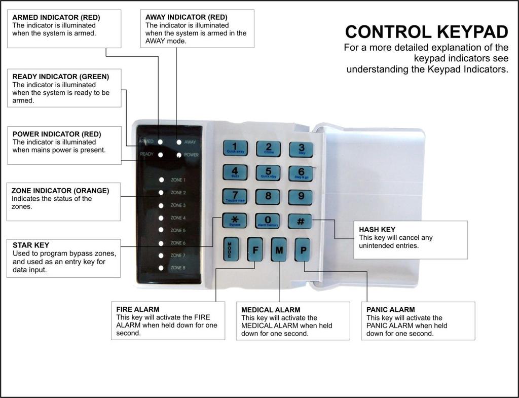
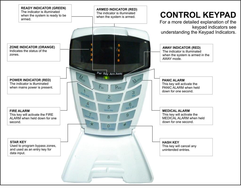
8 1. Introduction to the IDS805 The IDS805 Control Panel is manufactured to the highest specification and will provide many years of service if correctly installed and maintained. The unit is designed for simple operation yet provides the maximum protection for you, your family, or business. For trouble free operation, please follow the instructions contained in this User Manual. Your security system consists of a control panel, one or more keypads and various sensors and detectors. An enclosure will contain the control panel which includes the system electronics, fuses, and standby battery. There is normally no reason for anyone other than the installer or service professional to have access to the control panel. 1.1 Notes Read the entire manual carefully and keep it in an accessible place. Your security system should be installed and serviced by a qualified security professional who should instruct you regarding the level of protection provided and the operation of the system. Should you have any questions regarding the operation of the system, contact your security company representative. Your system should be tested on a regular basis. Before testing the system, please notify your security company of your intention to do so. NEVER disconnect the mains power, as the back-up battery will eventually discharge thereby causing the control panel to shutdown. A security system cannot prevent emergencies. It is only intended to alert you and - if included - your central station of an emergency situation. Smoke and heat detectors may not detect all fire situations. 2. Understanding the Keypad Indicators Refer to the labelled pictures of the keypads. 1. ARMED Indicator (Red) On Off Flashing System Armed System Disarmed Alarm Condition (Check Alarm Memory zone details BEFORE re-arming) 2. AWAY Indicator (Red) On Off Flashing System Armed in Away Mode System Disarmed / Armed in Stay Mode User Programming (Chime/Buzz/Stay zones) 8
9 3. POWER Indicator (Red) On Flashing Mains Power is Present Trouble Condition 4. READY Indicator (Green) On System is Ready to be Armed 5. ZONE Indicators (Yellow) On Off Flashing Zone Bypassed Zone Clear Zone Violated or Tampered 3. Operation of the Keypad To ensure correct operation of your security system it is essential to familiarize yourself with the use of the keypad. The keypad has a buzzer, command entry keys, zone and system status LED's. The keypad is used to send commands to the system and to display the current system status. The keypad(s) will be mounted in a convenient location within the protected premises generally close to the Entry/Exit zones. After a preprogrammed period of inactivity, the keypad will automatically enter into a power-save mode by turning off all the indicators. The keypad "wakes up" or comes on when any key is pressed or any zones are violated. The power save feature is programmable and may be disabled. A sensor which has registered an alarm condition will be indicated on the keypad by the corresponding zone light flashing. The keypad buzzer will sound under the following conditions. When any key is pressed during the entry of codes. Three times if one or more of the zones are violated when attempting to arm the system. To indicate a trouble condition. During the entry/exit delay. Will sound 5 times when a chime zone is violated. 9
10 4. System Information 4.1 Programmed Functions Check with your installer which of the following functions has been enabled. Quick Away Arm Quick Stay Arm Arm with Entry/Exit or Follower Zones Violated Stay Arm Stay Arm and Go Forced Arming Push to Arm Siren Sound on Arm/Disarm (single toot - arm/ double2 toot - disarm) Panic Alarm Fire Alarm Chime Zones Buzz Zones Zone Tamper Monitoring Arm with Key-switch or Remote Control Exit Delay with Key-switch or Remote Control Installers Reset after Alarm 4.2 User Codes User No. User Code User Name 01 Default Master Code: 1234 NEW Code: Maid s Code: 15 Duress Code: 10
11 4.3 Zone Information Zone Zone Type e.g. Entry/Exit Zone Name e.g. Kitchen Door The Primary Entry Delay is The Secondary Entry Delay is The Exit Delay Is Seconds Seconds Seconds 5. Arming the System There are various options for arming the system 5.1 Away Arming [#] + [USER CODE] (Leave via Entry/Exit Zone) 1. Ensure that the READY indicator is on; if not, check that all protected doors and windows are closed and that motion has ceased in areas covered by motion detectors. 2. If necessary, close the front door. 3. Press the [#] key to cancel any unintended key entries. 4. Enter a valid 4 digit [USER CODE]. If you make a mistake, press the [#] key and re-enter the code. 5. The ARMED indicator will come on and the keypad's buzzer will sound on and off for the duration of the exit delay. A steadily lit zone indicator will show any bypassed zones. 6. The arming process has begun. Leave only via the Follower and Entry/Exit zones. 7. The panel will arm at the end of the exit delay. OR If the panel is so programmed, violating the Push to Arm zone will arm the panel immediately. 5.2 Quick Away Arming Hold down the [1] key until the beep If this function is enabled, it is possible to AWAY arm by simply holding down the [1] key until the keypad buzzer sounds and the arming process begins. 11
12 5.3 Stay Arming This allows the user to arm the perimeter zones while disabling the interior zones so that it is possible to remain on the premises. If zones are likely to be violated accidentally, they should be programmed as BUZZ zones (refer to page 19). The panel can be programmed with two different STAY PROFILES to be used as required. Following is an example of where this may be used. Assume a property has perimeter sensors to secure a garden fence and a number of internal sensors within each room of the house. The first STAY PROFILE would function as follows: At night while you are within the house going about your normal evening activities it may be desirable to activate the alarm such that any violation of the perimeter sensors will cause an alarm. Therefore, this profile would have all internal sensors programmed as STAY zones (bypassed) and perimeter sensors would be normal alarm zones. A second STAY PROFILE would then be utilised once the family retires to their bedrooms. All bedrooms would therefore be STAY zones (bypassed) while unused zones i.e. a lounge and TV room, together with perimeter zones would be normal alarm zones. NOTE: Once a particular stay profile is selected, the system will use the selected profile each time the system is armed into the STAY MODE. If the alternate profile is required, it is necessary to select the alternate profile before the system is armed. The arming procedures and quick keys will have effect on the selected profile. STAY and BUZZ zones can be programmed for each profile once the profile has been entered To Enter a Stay Profile [#] + [MODE] + [9] + [PROFILE NUMBER] + [*] 1. Press the [#] key to clear any previous entries. 2. Press [MODE]. 3. Press [9] then press [1] or [2] for the required profile. 4. Press [*] to enter. A long beep should be heard. 5. Program STAY and BUZZ zones for the profile or ARM the profile (See sections 12 and 13) To Stay Arm [#] + [USER CODE] (Do not leave premises) 1. Select the required STAY PROFILE. 2. Ensure that the READY indicator is on; if not, check that all protected doors and windows are closed and that motion has ceased in the areas covered by motion detectors. 3. If necessary, close the front door. 4. Press the [#] key to cancel any unintended entries. 5. Enter a valid [USER CODE]. 6. The ARMED indicator will come on and the keypad buzzer will sound on and off for the duration of the exit delay. 7. DO NOT open the front door. If the front door is opened, the system will arm in AWAY mode. 8. The AWAY indicator will remain off. 9. Any STAY zones (shown by a steadily lit indicator) will be automatically bypassed. 10. Ensure that you enter only those zones that are bypassed. 12
13 5.4 Quick Stay Arming Hold down the [5] key until the beep It is possible to STAY arm by holding down the [5] key until the keypad beeps. There is no exit delay. 5.5 Stay Arm and Go Hold down the [6] key until the beep This is a quick function that allows the user to STAY arm and leave the premises. 1. Hold down the [6] key until the keypad buzzer sounds. The keypad buzzer will now sound on and off for the duration of the exit delay 2. At the end of the exit delay, the ARMED indicator will come on and the AWAY indicator will remain off. Any stay zones will be bypassed. 3. Be sure to leave only via the Follower and Entry/Exit zones. 5.6 Arming from a Key-switch or Remote Control There are several option related to this function. Verify with your installer which of the following have been installed: Key-switch or Remote Control installed Exit Delay with Key-switch or Remote Control Single toot on Arm Double toot on Disarm 1. Ensure that the READY indicator is on before leaving. 2. Leave and close the door (remembering to lock!). 3. Press the remote button or twist and release the key-switch. 4. The alarm will arm immediately and the remote ARM indicator will come on. OR If an exit delay has been enabled, the exit delay will begin. 5. If programmed to do so, the siren will sound briefly - verify with your installer. NOTE: If a remote control is used, it is advisable to have the siren sound on arm and disarm function enabled. 5.7 Auto Arming Your system can be programmed to automatically arm itself daily at a preprogrammed time. Ask your installer to program this function if required. Should the premises be occupied at the auto arming time, a valid [USER CODE] entered during the 3 minute arming cycle will cancel the process. 5.8 Arming with Entry/Exit or Follower Zones Violated The system can be programmed to arm even if the Entry/Exit or Follower zones are violated. Follow the normal arming procedures i.e. Enter a valid [USER CODE], but it is not necessary to close the front door. 13
14 5.9 Forced Arming If so programmed, the panel can be armed even if there are violated zones. This means that a monitored window can be left open or other zones can be violated and the panel will still arm. If the violated zone is then cleared, the panel will resume monitoring the zone, hence causing an alarm condition or initiation of entry delay, as appropriate, if violated. 6. Zone Bypassing The term BYPASS is used to describe a zone that has been deactivated; i.e. violation of a bypassed zone will not cause an alarm. It is used when access is needed to part of the protected area while the system is armed. Zones cannot be bypassed once the system is armed. Bypassed zones are automatically cancelled each time the system is disarmed and must be rebypassed before the next arming. 6.1 To Bypass a Zone [*] + [ZONE NUMBER] 1. Press the [*] key (while bypassing zones, violated zones will be flashing). 2. Press the number corresponding to the zone you need to bypass e.g. the [2] key if you wish to bypass zone The relevant zone indicator will come on to indicate that the zone is now bypassed. 4. Repeat steps 1 and 2 to bypass any other zones. 6.2 To Un-bypass a Zone [*] + [ZONE NUMBER] 1. Press the [*] key. 2. Press the number corresponding to the currently bypassed zone 3. The zone indicator will turn off - the zone is now active. 7. Disarming the System 7.1 Disarming with a User Code [#] + [USER CODE] To disarm the system, enter a valid [USER CODE] before the expiry of the entry delay. Although not essential, it is recommended that the [#] key be pressed before entering a user code as this clears any unintended key entries. Enter the premises through a designated Entry/Exit door. Entering via any other route will cause an alarm. As soon as the Entry/Exit zone is violated i.e. the door has been opened, the entry delay begins. The keypad buzzer will sound for the duration of the entry period to indicate that a valid user code is required. 14
15 If the ARMED indicator remains lit, an error was made while entering the user code, press the [#] key, and re-enter the code. Once the system disarms, the ARMED indicator will turn off and the keypad buzzer will stop sounding. If no valid user code has been entered by the end of the entry delay period, an alarm condition will be registered. If the entry period is too short, have your installer change the entry delay period. If four incorrect user codes are entered consecutively while either arming or disarming the system, the keypad will be non-responsive for 30 seconds. Your monitoring company will also be notified on a keypad tamper. NOTE: If the ARMED indicator is flashing upon entry, there has been a violation. The intruder may still be inside! Call for assistance. NOTE: If a strobe (or flashing light) has been installed and an alarm condition is registered, the light will continue flashing after the siren has stopped sounding. Entering a valid [USER CODE] will cancel the strobe. 7.2 To Disarm with a Key-switch or Remote Control 1. Press the remote button or twist and release the key-switch. 2. The system will disarm and the remote indicator (if installed) will turn off. 3. If programmed to do so, the siren will sound briefly - verify with your installer. 8. Emergency Situations 8.1 Fire Alarm Hold down the [F] key until the beep If the [F] key is pressed until the keypad beeps (approximately 1 second) a FIRE ALARM condition will be activated. The FIRE ALARM CONDITION can also be triggered by a smoke detector connected to an appropriately programmed zone. The siren will sound (1 second on, 1 second off) and the FIRE REPORTING CODE will be transmitted to the monitoring company. To silence the siren enter a 4 digit [USER CODE]. The siren will stop sounding after 10 minutes if no user code is entered. 8.2 Panic Alarm Hold down the [P] key until the beep If the [P] key is pressed until the keypad beeps (approximately 1 second) a PANIC ALARM condition will be activated. Any FIXED PANIC or REMOTE PANIC buttons which may have been installed can also activate a PANIC ALARM. If audible panic option has been selected, the siren will sound. A PANIC REPORTING CODE will be transmitted to the monitoring company. To silence the siren, enter a valid 4 digit [USER CODE]. If the siren is not cancelled, it will stop 15
16 automatically after the programmed SIREN TIME OUT period. Ensure that your installer has enabled this function if it is required. Press this key only in an emergency situation that requires response by emergency personnel. 8.3 Medical Alarm Hold down the [M] key until the beep If the [M] key is pressed until the keypad beeps (approximately 1 second) a MEDICAL ALARM condition will be activated. The keypad's buzzer will sound rapidly for 5 seconds to indicate that a medical alarm has been initiated. 8.4 Duress Code [#] + [DURESS CODE] This special 4 digit user code should only used in the unique situation where an intruder forces one to disarm the system "under duress". When the [DURESS CODE] is entered, the control panel disarms normally - however a DURESS REPORTING CODE is trans mitted to the monitoring company to inform them that you have been forced to disarm the control panel by an intruder. It is advisable to choose a code that can be easily remembered by all family (or staff) members. 9. Emergency Evacuation Plan An emergency evacuation plan should be established in case of a fire: Draw up a floor plan of your premises showing windows, doors, stairs, and rooftops that can be used for escape. Indicate a suitable escape route for each room. Always keep these routes free of obstruction. Establish a meeting place outdoors for a headcount of the building's occupants. Practice escape procedures. 10. System Memory 10.1 Alarm Memory The Alarm Memory displays any zones which were violated the last time the system was armed. If the ARMED indicator is flashing before you disarm the system, a violation has occurred. To view which zone was violated, disarm the panel, and continue as indicated below. To Display Alarm Memory: Hold down the [0] key until the beep 1. Hold down [0] until the keypad buzzer sounds. 2. The READY indicator will turn off and the keypad buzzer will sound briefly. 3. Flashing zone indicators show which zones were violated during the last armed period. 4. The memory status will be displayed for five seconds, or until the [#] is pressed. 16
17 5. The alarm memory will be erased the next time the system is armed Zone Bypassed Memory The Zone Bypassed Memory displays any zones which were bypassed during the most recent arming cycle. To Display Zone Bypassed Memory: [0] then [1] 1. Hold down [0] until the keypad buzzer sounds. 2. The READY indicator will turn off and the keypad buzzer will sound briefly. 3. Flashing zone indicators show which zones were violated during the last armed cycle. 4. To view any bypassed zones, press the [1] key once. 5. Zones that have been bypassed will have flashing indicators. 6. The memory status will be displayed for five seconds Zone Tamper Memory The Zone Tamper Memory displays any zones where a tamper condition has occurred. To Display Zone Tamper Memory: [0] then [2] 1. Hold down [0] until the keypad buzzer sounds. 2. The READY indicator will turn off and the keypad buzzer will sound briefly. 3. Flashing zone indicators show which zones were violated during the last armed cycle. 4. To view any tampered zones, press the [2] key once. 5. Zones that have registered a tamper condition will have flashing indicators. 6. The memory status will be displayed for five seconds. 11. User Codes The IDS805 Alarm Panel has 15 programmable user codes. Code 1: Master User Code Code 2 13: General User Codes Code 14: Maid s Code Code 15: Duress Code 11.1 Entering New and Changing Existing User Codes [*] + [MASTER USER CODE] + [*] + [CODE NUMBER] + [*] + [NEW CODE] + [*] 1. Hold down the [*] key until the keypad buzzer sounds. 2. The ARMED and READY indicators will flash alternately, indicating that the system is in the mode which allows programming of user codes. 3. Enter the [MASTER USER CODE] (the factory default is 1234) followed by the [*] key. 17
18 4. The ARMED and READY indicators will begin to flash simultaneously indicating that the correct master code was entered. If an invalid code was entered, the keypad buzzer will beep three times, and exit the programming mode. 5. Enter the [USER CODE NUMBER] you wish to change (1-15) followed by the [*] key. 6. Enter the new 4 digit [USER CODE] and press the [*] key. 7. Repeat steps 5-6 to enter or change other user codes. 8. Once all the codes are programmed, press the [#] key to exit Deleting User Codes Follow steps 1-5 of the previous procedure but only press the [*] key in step 6. That particular code will be deleted Maid s Code The maid s code (user 14) may be used to limit access to the premises. The maid s code will only disarm the system if the same code was used for arming. If armed with a code other than a maid s code, the system will view an attempt to disarm with the maid s code as an invalid entry. Any valid user code will disarm the system if it has been armed with the maid s code. EXAMPLE: If a maid is expected on a Monday, arming the system on a Monday morning using the maid s code will allow the maid to disarm the system. On days that any other user code (i.e. not a maid s code) has been used to arm the system entering the maid s code will not disarm the system. 12. Stay Zones Stay zones are those zones which are bypassed automatically when the system is STAY ARMED. To avoid triggering the alarm, zones such as bedrooms, or other areas which require access, must be bypassed. Stay zones need only be programmed once. Each time the system is armed in the stay mode the preselected stay zones will be bypassed automatically. This also depends on which stay prifle is active (5.3.1). NOTE: Instant zones, such as panic zones, cannot be selected To Program Stay Zones [3] + [ZONE NUMBER] + [*] + [#] 1. Hold down the [3] key until the keypad buzzer sounds. The AWAY indicator will flash to show that the panel is in the Stay Zone programming mode. 2. Press the [NUMBER] corresponding to the zone you wish to be a STAY zone. 3. The relevant zone indicator will come on. (Buzz zones will be shown by flashing indicators. See Section 13. A Buzz zone cannot be selected as a Stay zone; the Buzz status must be cleared first.) 4. Repeat step 2 until all stay zones are selected. 5. Press the [#] key to exit the Stay zone programming mode. 18
19 12.2 To Cancel the Stay Zones [3] + [ZONE NUMBER] + [*] + [#] If an area programmed as a STAY zone will no longer be violated during STAY arming, then the STAY status of such a zone should be cancelled. This will allow the system to protect that area during a stay arm cycle. 1. Hold down the [3] key until the keypad buzzer sounds. The AWAY indicator will flash to show that the panel is in the Stay zone programming mode. 2. Press the [NUMBER] corresponding to the STAY zone you wish to cancel. 3. The relevant zone indicator will turn off. 4. Repeat step 2 until all stay zones are selected. 5. Press the [#] key to exit the Stay zone programming mode. NOTE: The system will automatically exit this mode after 60 seconds. 13. Buzz Zones Buzz zones are used when Stay arming. When triggered, buzz zones will cause the keypad buzzer to sound for a period of 30 seconds during which time a valid user code must be entered. If a valid user code is not entered during this period, the system will register an alarm condition. It is advisable to program Buzz zones if you are likely to accidentally trigger these zones or if you have pets. This feature helps prevent unnecessary false alarms. NOTE: Instant zones, such as panic zones, cannot be selected To Program Buzz Zones [4] + [ZONE NUMBER] + [*] + [#] 1. Hold down the [4] key until the keypad buzzer sounds. The AWAY indicator will flash to show that the panel is armed in the Buzz zone programming mode. 2. Press the [NUMBER] corresponding to the zone you wish to be a Buzz zone. 3. The lit zone indicator will show the relevant Buzz zone. (Stay zones will be shown by flashing indicators. See Section 12. A Stay zone cannot be selected as a Buzz zone; the Stay status must be cleared first). 4. Repeat steps 2 until all the required Buzz zones are programmed. 5. Press the [#] key to exit the buzz programming mode. 19
20 13.2 To Cancel Buzz Zones [4] + [ZONE NUMBER] + [*] + [#] 1. Hold down the [4] key until the keypad buzzer sounds. The AWAY indicator will flash to show that the panel is armed in the Buzz zone programming mode. 2. Press the [NUMBER] corresponding to the BUZZ zone you wish to cancel. 3. The relevant zone indicator will turn off. 4. Repeat step 2 until all buzz zones are cancelled. 5. Press the [#] key to exit the buzz zone programming mode. NOTE: The system will automatically exit this mode after 60 seconds. 14. Chime Zones The chime mode allows the user to monitor nominated zones while the system is disarmed. The keypad buzzer will sound 5 times when the nominated zone is violated - the siren will NOT sound and no alarm condition will be reported. EXAMPLE: You wish to know when someone enters or exits the front door; the keypad will beep each time the door is opened if that zone is programmed as a chime zone To Program the Chime Zones [2] + [ZONE NUMBER] + [*] + [#] 1. Hold down the [2] key until the keypad buzzer sounds. 2. The AWAY indicator will flash to show that the panel is in the chime zone programming mode. 3. To program a zone as a chime zone, press the key corresponding to that zone. The zone indicator will come on. 4. Program any other zones you wish to select as chime zones as per step Press the [#] key to exit the chime programming mode To Cancel the Chime Zones [2] + [ZONE NUMBER] + [*] + [#] 1. Hold down the [2] key until the keypad buzzer sounds. 2. The AWAY indicator will flash to show that the panel is on the chime programming mode. 3. To cancel any chime zones, press the key corresponding to that zone. The zone indicator will turn off. 4. Repeat step 3 until all the chime zones are cancelled. 5. Press the [#] key to exit the chime programming mode. NOTE: The system will automatically exit this mode after 60 seconds. 20
21 15. Troubleshooting 15.1 Trouble Conditions In the event of a trouble condition the power indicator will flash. Trouble Condition refers to Low Battery power and/or AC Mains Failure. Check that the plug is in place and switched on. If the power indicator is still flashing once these checks have been done, contact your installer who will then check the battery power Viewing Trouble Conditions Hold down the [7] until the beep If the POWER LED is flashing (or if so programmed, the keypad is beeping) hold down the [7] key for one second. The ARMED, AWAY, and READY indicators will start flashing to show that the keypad is in the TROUBLE viewing mode. Refer to the table below to find the significance of each lit zone LED. The system will automatically exit the TROUBLE mode after ten seconds. To clear the trouble condition press [#] within 5 seconds of viewing. To simply cancel the beeping without viewing the trouble conditions, press [#]. Indicator Trouble Condition 2 Failure to communicate to monitoring company 3 Mains power failure 4 Low battery 5 The Telephone line has been cut or is not present 6 The siren wire has been cut or the fuse has blown 7 Keypad has experienced a tamper 8 Installers code must be entered to clear an alarm condition 15.2 Problems when Arming the System If you enter the wrong user code, the keypad will beep three times and the system will not arm. Is the READY Indicator on? If this indicator is not on, one or more zones are violated. A flashing zone indicator shows a violation. Ensure that all monitored doors and windows are closed. Bypassing a violated zone will also create a READY condition. Does the siren sound before you exit? The exit delay may be too short - ask your installer to adjust the exit delay. OR You have not left via a Follower and Entry/Exit zone or have strayed into an Instant zone. Either avoid these zones or ask your installer to change the zone type. 21
22 15.3 Problems when Disarming the System Does the siren sound immediately upon entry? You have not entered via the Entry/Exit zone or have strayed into an Instant zone. Does the siren sound before you get to the keypad? You have strayed into a non-follower zone OR You have taken too long to get to the keypad. The panel will not disarm. You may have entered an incorrect code. Press the [#] key first, then re-enter your user code For Service Central Station Information: Account #: Installer Information Account #: Telephone Telephone 22
23 Index Alarm Memory...7, 8, 16, 17, 27 Arm...7, 8, 10, 11, 21, 27 Away...11 Quick Away...10, 11, 27 Quick Stay...10, 13, 27 Quick Stay & Go...10, 13, 27 Stay...7, 10, 12, 18, 19, 27 Stay & Go... 7, 10 Away Mode...8, 12 Auto Arming13 Battery...,8, 21 Buzz Zone...10, 12, 18, 19, 20 Bypass...7, 9, 11, 12, 13, 14, 16, 17, 18, 21, 27 A B C Control Panel...8, 16 Chime...8, 9, 10, 20, 27 Disarm...7, 8, 10, 13, 14, 15, 16, 18, 20, 22, 27 Duress...10, 16, 17, 27 Emergency Evacuation...16 Entry Delay...8, 13, 14, 15 Primary...11 Secondary...11 Entry/ Exit Zone...see "Zone" Exit Delay...7, 8, 10, 11, 12, 13, 21 Fire...7, 8, 10, 15, 16, 27 Follower Zone...see "Zone" Forced Arming...10, 14 Installer Code...21 Instant Zone...see "Zone" D E F I Key-switch...10, 13, 15 K 23
24 Maid s Code...10, 17, 18 Master User Code...17, 18 Medical...7, 16, 27 Panic...7, 10, 14, 15, 16, 27 Problems...21, 22 Push to Arm Zone...see "Zone" Quick Away Arming...see "Arm" Quick Stay Arming...see "Arm" Quick Stay Arm & Go...see "Arm" Remote Control...see "Key-switch" Reporting Code...7 Siren...10, 13, 15, 16, 20, 21, 22 Stay Arm...see "Arm" Stay Arm & Go...see "Arm" Stay Mode...8, 12, 18 Stay Profile...12, 27 Strobe...15 Tamper...9, 10, 15, 17, 21 Testing...8 Trouble Condition...9, 21 Trouble Mode...21 Trouble Status...27 User Codes...10, 15, 17, 18 Zones Entry/ Exit...7, 9, 10, 11, 13, 15, 22 Follower...7, 10, 11, 13, 22 Instant...7, 22 Push to Arm...10, 11 Stay...7, 8, 12, 13, 18, 19, 27 M P Q R S T U Z 24
25 25
26 26
27 Quick Reference User Guide Arm/Disarm [#] + [USER CODE] Quick Away Arm Hold down [1] for 1 second Quick Stay Arm Hold down [5] for 1 second Quick Stay Arm & Go Hold down [6] for 1 second Panic Hold down [P] for 1 second Fire Hold down [F] for 1 second Medical Emergency Hold down [M] for 1 second Alarm Memory Hold down [0] for 1 second Change Stay Profile [MODE] + [9] + [PROFILE NUMBER] + [*] Bypass a zone [*] + [ZONE NUMBER] Program chime zone Hold down [2] for 1 second + [ZONE NUMBER] + [*] Program stay zone Hold down [3] for 1 second + [ZONE NUMBER] + [*] Program buzz zone Hold down [4] for 1 second + [ZONE NUMBER] + [*] View Trouble Status Hold down [7] for 1 second Duress [#] + [DURESS CODE] 27
28 28
IDS800 USER MANUAL. Summary of Operation. + [ ] 2 IDS800 USER MANUAL NO K ISSUED APR 2003 VER 1.44
![IDS800 USER MANUAL. Summary of Operation. + [ ] 2 IDS800 USER MANUAL NO K ISSUED APR 2003 VER 1.44](/thumbs/89/98095999.jpg "IDS800 USER MANUAL. Summary of Operation. + [ ] 2 IDS800 USER MANUAL NO K ISSUED APR 2003 VER 1.44") Summary of Operation A rm/ disarm [#] + [USER CODE] Quick Quick Quick Away Arm Stay Arm Stay Arm & Go H old down [ 1] for 1 second H old down [ 5] for 1 second H old down [ 6] for 1 second Panic Fire Medical
Summary of Operation A rm/ disarm [#] + [USER CODE] Quick Quick Quick Away Arm Stay Arm Stay Arm & Go H old down [ 1] for 1 second H old down [ 5] for 1 second H old down [ 6] for 1 second Panic Fire Medical
IDS816 User Manual H Issued January 2009
 1 Contents Glossary-------------------------------------------------------------------------------------------------------------------6 1. Introduction to the IDS 816---------------------------------------------------------------------------7
Contents. Glossary
 Contents Glossary ------------------------------------------------------------------------------------------------------ 6 1. Introduction to the IDS 1632 -------------------------------------------------------------
IDS S E C U R I T Y IDS816. User Manual. MANUAL NO A ISSUED November 2004 VERSION 1.00
 INHEP DIGITAL IDS S E C U R I T Y IDS816 User Manual MANUAL NO. 700-283-02A ISSUED November 2004 VERSION 1.00 Contents 1. Introduction to the IDS816... 4 2. Understanding the Keypad Indicators... 4 3.
Watchguard WGAP864 User Manual
 Watchguard WGAP864 User Manual v1.0 Issued September 2016 1 2 Table of Contents Glossary... 5 1. Introduction to your Watchguard WGAP864... 6 2. Before Operating your Alarm System... 6 3. Understanding
IDS S E C U R I T Y IDS816. User Manual MANUAL NO B ISSUED DEC 2004 VERSION 2.00
 INHEP DIGITAL IDS S E C U R I T Y IDS816 User Manual MANUAL NO. 700-283-01 B ISSUED DEC 2004 VERSION 2.00 Contents 1. Introduction to the IDS816... 4 2. Understanding the Keypad Indicators... 4 3. Programmable
L900 series USER MANUAL
 INTRODUCTION The BLUGUARD Control Panel is designed for simple operation yet provides the maximum protection for you. Please read this manual carefully and follow the instructions contained in this book.
IDS S E C U R I T Y IDS816. User Manual MANUAL NO C ISSUED APRIL 2005 VERSION 2.00
 INHEP DIGITAL IDS S E C U R I T Y IDS816 User Manual MANUAL NO. 700-283-01C ISSUED APRIL 2005 VERSION 2.00 Contents 1. Introduction to the IDS816... 4 2. Understanding the Keypad Indicators... 4 3. Programmable
HILLS Series LED Code Pad User Manual
 HILLS Series LED Code Pad User Manual Not all features may be available on your system Check with your installer to find out which features are programmed Page 2 TABLE OF CONTENTS Code Pad Diagrams...2
SPECIAL CODES AUXILIARY CODES SYSTEM NOTES
 Installing/Service Company For Service Call SPECIAL CODES Master Code Duress Code AUXILIARY CODES "Quick Arm" " Chime" 08 02 09 03 10 04 11 05 12 06 13 07 14 SYSTEM NOTES Exit Delay Time Entry Delay Time
SECURITY SYSTEM NOTES SPECIAL CODES ENTRY / EXIT DELAY TIMES ARM / DISARM CODES ZONE DESCRIPTIONS
 SECURITY SYSTEM NOTES Installing/Service Company For Service Call SPECIAL CODES "Chime" Digit 1 "Partial Arm" Digit 2 "Quick Arm" Digit 3 ENTRY / EXIT DELAY TIMES Exit Delay Time Entry Delay Time Secondary
User s Information Guide R2A
 Pi HSC505 Home Security Controller User s Information Guide R2A Page 1 of 15 of its development program. 1This document and product are copyrighted and all rights are reserved. Introduction Convention
NX-148 LCD CODE PAD TABLE OF CONTENTS
 NX-148 LCD CODE PAD TABLE OF CONTENTS Glossary Of Terms... 4 Understanding The Lights... 5 Code Pad Functions Arming In The ON Mode... 6 Making The System Ready To Arm... 7 Using Quick Arm... 7 Arming
SPECIAL CODES AUXILIARY CODES SYSTEM NOTES
 Installing / Service Company Monitoring Station SPECIAL CODES Master Code Duress Code AUXILIARY CODES "Quick Arm" "Chime" 08 02 09 03 10 04 11 05 12 06 13 07 14 SYSTEM NOTES Exit Delay Time Entry Delay
SECURITY SYSTEM NOTES
 SECURITY SYSTEM NOTES Installing/Service Company For Service Call Central Station Duress Code FUNCTION CODES Function Code Controls Function EMERGENCY ACTIVATION KEYS (check if enabled) Fire Auxiliary
NetworX NX-8V2. LED Keypad User Manual
 NetworX NX-8V2 LED Keypad User Manual POWER Light is on when AC power is present; flashes to indicate a low battery condition. ARMED Light is on when armed; off when disarmed; flashes to indicate a previous
NETWORX TM. User manual NX-4
 NETWORX TM User manual NX-4 POWER Light is on when AC power is present; flashes to indicate a low battery condition. ARMED Light is on when armed; off when disarmed; flashes to indicate a previous alarm.
PROGRAMMING PROCEDURES (Table 3)
") CONDOPLEX 2600/2600A/2700 Suite Panel User Manual Document Version 8.4 Oct 19, 1998 Condoplex 1998 PROGRAMMING PROCEDURES (Table 3) FUNCTION PRESS KEYPAD DISPLAY Delete user code or duress code. 0 (hold)
CONDOPLEX 2600/2600A/2700 Suite Panel User Manual Document Version 8.4 Oct 19, 1998 Condoplex 1998 PROGRAMMING PROCEDURES (Table 3) FUNCTION PRESS KEYPAD DISPLAY Delete user code or duress code. 0 (hold)
NetworX Series NX-1500E LED Keypad
 NetworX Series NX-1500E LED Keypad User Manual SECURITY SYSTEM NOTES Installing/Service Company For Service Call Central Station Duress Code FUNCTION CODES Function Code Controls Function This system
ABORT Light flashes during an abort delay time; is on during or after an alarm report to the central station. EMERGENCY ACTIVATION KEYS
 POWER Light is on when AC power is present; flashes to indicate a low battery condition. CHIME Light is on when the chime feature is active. ABORT Light flashes during an abort delay time; is on during
Master Code Arming Auto-Bypass Option - Home-Away Arming Entry Delay Off Arming
 Master Code The 4 digit Master Code is used for arming and disarming the system, for programming additional access codes, and for changing other features. The Master Code will be supplied to you by your
AXI LED USER MANUAL (REV. 1.0)
") Security & Home Automation System AXI LED USER MANUAL (REV. 1.0) CONTENTS PREFACE FEATURES LED KEYPAD OUTLOOK 1.0 LIGHT INDICATION 1 2 4 6 CHAPTER 1: ALARM SYSTEM CONTROL 1.0 USING LED KEYPAD 1.0.1 ARMING
Security & Home Automation System AXI LED USER MANUAL (REV. 1.0) CONTENTS PREFACE FEATURES LED KEYPAD OUTLOOK 1.0 LIGHT INDICATION 1 2 4 6 CHAPTER 1: ALARM SYSTEM CONTROL 1.0 USING LED KEYPAD 1.0.1 ARMING
Understanding the Code Pad lights...4. Code Pad tones...5. Fully arming the system On MODE...6. Fully arming the system - Quick Arm MODE...
 TABLE OF CONTENTS...Glossary of terms...2...code Pad Diagram...3 Understanding the Code Pad lights...4 Code Pad tones...5 Fully arming the system On MODE...6 Fully arming the system - Quick Arm MODE...6
Using Your. Security System With LED Keypad S5030, S5031, S5032
 Using Your Security System With LED Keypad S5030, S5031, S5032 Contents 1 Overview Your Security System... 1 How Your Security System Works... 2 Your System's Programming... 3 Getting Used to Your System...
LED Keypads D720 Series User s Guide
 LED Keypads D720 Series User s Guide D720 D720W D720B Table of Contents Fire Safety 3 The D720/D720W/D720B Keypad 4 Security System Basics 5 Turning the System On and Off 7 Silencing and Reporting Alarms
OPERATING GUIDE FOR YOUR RP1054D KEYPAD
 OPERATING GUIDE FOR YOUR RP1054D KEYPAD Napco 1992 DESIGN PATS. PENDING Technical Manuals Online! - http://www.tech-man.com CONGRATULATIONS!...on your purchase of a NAPCO Magnum Alert security system.
Destiny Destiny Owners Manual
 Destiny 4100 Destiny 4100 Owners Manual TABLE OF CONTENTS INTRODUCTION Control Panel...3 Detection Devices...3 Telephone Keypads...3 GLOSSARY... 4-5 LOCAL PHONE ACCESS Using Your Telephones As Keypads...6
Condominium Security Management System
 User Access Codes The CONDOPLEX series panels can be programmed with nine (9) different user codes and one (1) duress code. User codes are normally used for arming and disarming the panel. The duress code
Solution Ultima 862 Operators Manual ISSUE 1.10
 Solution Ultima 862 Operators Manual ISSUE 1.10 Solution Ultima 862 Operators Manual Copyright 2001 by, SYDNEY, AUSTRALIA Document Part Number MA486O DOCUMENT ISSUE 1.10 Printed 24 April 2001 This documentation
User s Guide. SUB-MA7240O-0001.OG.Solution doc. Created: 6/05/03. Last Updated: 23/09/03. MA7240AO-0001 Version 1.0
 User s Guide SUB-MA7240O-0001.OG.Solution40-111.doc Created: 6/05/03 Last Updated: 23/09/03 MA7240AO-0001 Version 1.0 2 Table Of Contents User List...6 Quick Reference..7 Features...7 Keypad User's Guide...8
Security System. User Guide for the LED Command Center
 Security System User Guide for the LED Command Center National Security Systems Inc (800)457-1999 MY SECURITY COMPANY IS: CALL BEFORE TEST: THIS SECURITY SYSTEM IS CONNECTED TO TELEPHONE NUMBER: THE SECURITY
Elite 16D Version 16 Zone Controller Arrowhead Alarm Products Ltd. Operating Guide. Proudly Designed and Manufactured in New Zealand
 6 Elite 16D Version 16 Zone Controller Arrowhead Alarm Products Ltd Operating Guide 1 Proudly Designed and Manufactured in New Zealand CONTENTS Page No. INTRODUCTION 3 About your Alarm 3 OPERATING YOUR
DESTINY OWNER S MANUAL
 DESTINY OWNER S MANUAL DESTINY You have made a wise decision to protect your family and property with the DESTINY Security System. The DESTINY has been designed to provide you with a maximum level of security
INSTRUCTION MANUAL PC255O
 INSTRUCTION MANUAL PC255O Canadian Department of Communications Notice NOTICE: The Canadian Department of Communications label identifies certified equipment. This certification means that the equipment
INSTRUCTION MANUAL PC255O
 INSTRUCTION MANUAL PC255O Canadian Department of Communications Notice NOTICE: The Canadian Department of Communications label identifies certified equipment. This certification means that the equipment
Digiplex LED Keypads User s Manual
 KLEDEU03.fm Page -1 Friday, May 4, 2001 11:25 AM Digiplex LED Keypads User s Manual KLEDEU03.fm Page 0 Friday, May 4, 2001 11:25 AM KLEDEU03.fm Page 1 Friday, May 4, 2001 11:25 AM TABLE OF CONTENTS 1.0
DESTINY 6100 SERIES SECURITY SYSTEM OWNER S MANUAL V1 12/01
 DESTINY 6100 SERIES SECURITY SYSTEM OWNER S MANUAL 800-6006V1 12/01 System Overview General Information Control Panel Detection Devices You have made a wise decision to protect your family and property
Alarm Control Panel WIC-16Z4P WIC-5Z2P. User Instructions
 WIC-16Z4P WIC-5Z2P User Instructions Page : 2/14 INDEX # Function Page 1 Add a New User Code 11 2 Arm or Disarm All Areas or Disarm Selected Areas (Partitioned System) 8 3 Arming the System (Away Mode)
Solution 844 Operators Manual ISSUE 1.10
 Solution 844 Operators Manual ISSUE 1.10 Solution 844 Operators Manual Copyright 2001 by, SYDNEY, AUSTRALIA Document Part Number MA406O DOCUMENT ISSUE 1.10 Printed 24 April 2001 This documentation is provided
Solution Ultima Series Operators Manual ISSUE 1.00
 Solution Ultima Series Operators Manual ISSUE 1.00 Solution Ultima Series Operators Manual Copyright 1998 by, SYDNEY, AUSTRALIA Document Part Number MA488O DOCUMENT ISSUE 1.00 Printed 16 February 1999
D1265. User's Guide. Touchscreen Keypad
 D1265 EN User's Guide Touchscreen Keypad D1265 User's Guide Contents This system includes a telephone line seizure feature. The system can be programmed to communicate with a central monitoring station
636 and 646 Keypads. User s Manual
 636 and 646 Keypads 636 646 User s Manual Table Of Contents Basic Operation... 2 Access Codes... 4 Arming & Disarming... 5 Panic Zones... 11 Key Access Programming... 12 Additional Features... 13 Trouble
Table of Contents. Appendix A Special Characters 31
 Table of Contents Introduction 2 Section 1: General System Operation 3 1.1 Getting to Know Your System... 3 1.2 How to Arm... 4 1.3 Alternate Arming Methods... 5 1.4 Disarming... 6 1.5 Alarm Memory...
0 4 / 0 4 / 1 4. GE Concord 4 Quick User Guide. GE Concord 4 Quick User Guide Page 1
 0 4 / 0 4 / 1 4 GE Concord 4 Quick User Guide GE Concord 4 Quick User Guide Page 1 Before Calling Is the keypad beeping? Press *. This will silence the beeping and let you know where the trouble is. Is
TS400 & TS410. Intruder Alarm Control Panels. Operating Instructions
 TS400 & TS410 Intruder Alarm Control Panels Operating Instructions Zone Location Home Set Chime 1 Armed / Omitted 2 Armed / Omitted 3 Armed / Omitted 4 Armed / Omitted 5 Armed / Omitted F. Exit Always
Security System. User s Guide for the Text Command Center
 User s Guide for the Text Command Center MY ALARM COMPANY IS: CALL BEFORE TEST: THIS SECURITY SYSTEM IS CONNECTED TO TELEPHONE NUMBER: THE SECURITY CONTROL PANEL IS CONNECTED TO THE PHONE JACK LOCATED:
Solution 880 Operators Manual. Issue 1.00
 Solution 880 Operators Manual Issue 1.00 Solution 880 Operators Manual Copyright 1998 by, SYDNEY, AUSTRALIA Document Part Number MA408O Document ISSUE 1.00 Printed 15 June 1998 This documentation is provided
U ser's Guide PC6010
 User's Guide PC6010 Quick Reference Guide This manual is for Basic and Advanced users. Each of these types of user can access a different set of functions. The and symbols next to the title of each procedure
Power864. User s Guide. Now classified in accordance with ANSI/SIA CP (SIA-FAR)
") WARNING This manual contains information on limitations regarding product use and function and information on the limitations as to liability of the manufacturer. The entire manual should be carefully
WARNING This manual contains information on limitations regarding product use and function and information on the limitations as to liability of the manufacturer. The entire manual should be carefully
Digiplex LED Keypads. User s Manual
 Digiplex LED Keypads User s Manual TABLE OF CONTENTS INTRODUCTION... 6 1.1 Legend...6 BASIC OPERATION... 7 2.1 Auditory Feedback (Beep Tones)...8 2.2 Keypad Indicator Lights...8 2.3 LED Keypads...8 2.4
Ultra-8D. ControlPanel. Operators Manual. Advanced DigitalControls CP108-0M-V1
 Ultra-8D ControlPanel Operators Manual Advanced DigitalControls CP108-0M-V1 ULTRA-8D CONTROL PANEL AS108 OPERATORS MANUAL Copyright 2001 by Advanced Digital Controls NZ Ltd Auckland, New Zealand Document
Table of Contents. Page Code
 Table of Contents Introduction Command Center Function Keys Security System Basics Your Custom Display View Faulted or Bypassed Points Warning Displays and Tones Fire Alarms Burglary Alarms Fire Trouble
Protégé Eclipse LED Keypad User Manual PRT-KLES
 Protégé Eclipse LED Keypad User Manual PRT-KLES The specifications and descriptions of products and services contained in this manual were correct at the time of printing. Integrated Control Technology
Elite 64 Version 64 Zone Controller Arrowhead Alarm Products Ltd. Operating Guide. Proudly Designed and Manufactured in New Zealand
 2 Elite 64 Version 64 Zone Controller Arrowhead Alarm Products Ltd Operating Guide Proudly Designed and Manufactured in New Zealand 1 CONTENTS Page No. INTRODUCTION 3 About your Alarm 3 OPERATING YOUR
Wireless Keypads LKP(E)S8M Series
S8M Series") Wireless Keypads LKP(E)S8M Series User manual Contents Congratulations on your purchase of this Honeywell wireless keypad. To make the best out of your equipment we advise you to read this manual carefully.
Wireless Keypads LKP(E)S8M Series User manual Contents Congratulations on your purchase of this Honeywell wireless keypad. To make the best out of your equipment we advise you to read this manual carefully.
Power Wave LCD Keypads. Users Operating and Programming Guide Version 2.00
 Power Wave LCD Keypads CR-16S CR-16M Users Operating and Programming Guide Version 2.00 P/N 7102265 Rev. C N.A May 2003 Contents Introduction...4 Meet the PowerWave Alarm Control System... 4 Typical Alarm
HARDWIRED CONTROL PANELS
 USER GUIDE 9651 HARDWIRED CONTROL PANELS Contents 1. Introduction...3 The Alarm System...3 The Keypad...3 About This Guide...5 2. Everyday Operation...6 How Do I Know if the System is Working?...6 Setting
About Your Security System. General System Operation. Fire Detection. Testing. Monitoring
 About Your Security System Your DSC security equipment has been designed to provide you with the greatest possible flexibility and convenience. Read this manual carefully and have your installer instruct
Tomorrow s technology for today s security needs.
 Tomorrow s technology for today s security needs. The Security Command Keypad Welcome Congratulations on your decision to purchase a Security Command system. The new Security Command keypad, from one of
Version 1.03 January-2002 USER S MANUAL
 Version 1.03 January-2002 1 USER S MANUAL 2 Version 1.03 January-2002 System Details CUSTOMER:...... PHONE:... FAX:... INSTALLED BY:...... PHONE:... FAX:... MAINTENANCE & SERVICE:...... PHONE:... FAX:...
10-Zone Spectra LED Keypads
 10-Zone Spectra LED Keypads User s Guide TABLE OF CONTENTS Introduction... 5 Basic Operation... 6 Auditory Feedback... 6 Keypad Indicator Lights... 8 Zone Display... 8 Alarm Memory Display... 8 Trouble
 Solution-6 Operators Manual Page 1 Preface Congratulations on selecting the Solution-6 security control system for your installation. So that you can obtain the most from your unit, we suggest that you
8 plus and16 plus. User s Guide * # ent. esc GALAXY 16+ V2.XX TUE 30 JUN. IU ZST 962 Issue 2. A u B u
 8 plus and16 plus User s Guide GALAXY 16+ V2.XX 06.22 TUE 30 JUN 1 2 3 4 5 6 7 8 9 0 * # A u B u ent esc IU1-0018 ZST 962 Issue 2 Contents INTRODUCTION... 1 Glossary of Terms... 3 KEYPAD INFORMATION...
PowerWave-16. Users Operating and Programming Guide Version P/N Rev. B N.A July 2002
 ELECTRONIC ENGINEERING LTD. PowerWave-16 16 zone Control panel Communicator Users Operating and Programming Guide Version 6.20 P/N 7121240 Rev. B N.A July 2002 Contents Introduction...4 Meet the Crow Alarm
OPERATING GUIDE for your GEM-RP1CAe2 KEYPAD
 OPERATING GUIDE for your GEM-RP1CAe2 KEYPAD GEMINI SYSTEM READY 09/01/05 12:09 AM ARMED STATUS A 1 2 3 B 4 5 6 J C 7 8 9 0 NEXT / YES E PRIOR / NO F AREA G COMPUTERIZED SECURITY SYSTEM Simplified instructions
USER GUIDE HARDWIRED CONTROL PANELS
 USER GUIDE HARDWIRED CONTROL PANELS Scantronic Contents 1. Introduction... 3 The Alarm System... 3 The Keypads... 3 The 725r Remote Setting Device... 6 About This Guide... 6 2. Everyday Operation... 7
SPECTRA 1727 USER S GUIDE
 SPECTRA 1727 USER S GUIDE TABLE OF CONTENTS 1.0 INTRODUCTION... 3 2.0 BASIC OPERATION... 4 2.1 Auditory Feedback...4 2.2 Keypad Indicator Lights...6 2.3 Zone Display...6 2.4 Alarm Memory Display...6 3.0
Total Connect Box. User manual
 Total Connect Box User manual 1 Congratulations on your purchase of the Honeywell Total Connect Box security system. To make the best out of your system we advise you to read this manual carefully. This
Paradox Security System Graphic Dept - PRINTED IN CANADA. keypad entries in memory. arming permits movement in pre-selected,
 970213-0001 ESPRIT 727 U LISTED User Manual VERSION 3.3 P R D O X S E C U R I T Y S Y S T E M S Paradox Security System Graphic Dept - PRINTED IN CANADA READY The green LED must be " on", indicating all
ESPRIT 616/626 KEYPADS. User Manual P R D O X S E C U R I T Y S Y S T E M S. Model 626 READY UM ESPRIT PRINTED IN CANADA 2ND TRBL
 ESPRIT 616/626 KEYPADS LISTED U User Manual READY ARMED Model616 2ND TRBL MEM BYP 1 2 4 7 0 3 5 6 8 9 11 10 AWAY STAY CLEAR ENTER 12 Model 626 READY ARMED ESPRIT P R D O X S E C U R I T Y S Y S T E M S
Quick Reference Guide
 WARNING This manual contains information on limitations regarding product use and function and information on the limitations as to liability of the manufacturer. The entire manual should be carefully
LCD and 16-Zone LED Keypads. User s Manual
 LCD and 16-Zone LED Keypads 1689 1641 16-Zone LED Keypad LCD Keypad User s Manual TABLE OF CONTENTS 1.0 INTRODUCTION...3 2.0 BASIC OPERATION...4 2.1 Keypad Indicator Lights... 4 2.2 Visual Feedback...
The most user friendly Security Alarm System L S Section 1 Overview of System Section 2 Planning your Installation
 The most user friendly Contents Section 1 Overview of System 1.1 Kit Contents 1.2 Tools Required 1.3 System Features Security Alarm System L S 4 0 0 Section 2 Planning your Installation 2.1 Location of
HA-263K HA-263D. OWNER'S MANUAL Installation And Operation 8-ZONE ALARM CONTROL PANEL FOR HOME AND OFFICE PROTECTIONS OPEN THE CABINET FOR SERVICE
 D (OPERATION) INITIATE A DYNAMIC BATTERY TEST The system tests the back-up battery once every 24 hours. The owner can initiate a dynamic battery test at any time with the following codes while the system
EasyLoader. End User Manual
 EasyLoader End User Manual Table of Contents Table of Contents... 1 System Configuration... 3 Introduction... 4 SAFETY AND MAINTENANCE INSTRUCTIONS... 4 GLOSSARY... 4 Basic Operations... 8 ARMING YOUR
3 User s settings. 3.3 Internal clock setting
 2.9 Subsystem arming In a large building a sub control panel can be enrolled to the JA-63. The subsystem reports all alarms and failures to the main system. The installer can program if the systems will
RANGER 7600 DOWNLOADABLE CONTROL COMMUNICATOR INSTALLATION MANUAL
 RANGER 7600 DOWNLOADABLE CONTROL COMMUNICATOR INSTALLATION MANUAL TABLE OF CONTENTS 1. TABLE OF CONTENTS... P.1 2. GENERAL DESCRIPTION... P.2... 3. STANDARD AND OPTIONAL PARTS LIST... P.2... 4. FEATURE
Elite 16D Version 16 Zone Controller Arrowhead Alarm Products Ltd. Operating Guide. Proudly Designed and Manufactured in New Zealand
 5 Elite 16D Version 16 Zone Controller Arrowhead Alarm Products Ltd Operating Guide Proudly Designed and Manufactured in New Zealand About your Alarm Controller Thank you for choosing to protect your premises
HILLS Series LCD Code Pad User Manual
 HILLS Series LCD Code Pad User Manual THIS MANUAL IS FURNISHED TO HELP YOU UNDERSTAND YOUR SECURITY SYSTEM AND BECOME PROFICIENT IN ITS OPERATION. ALL USERS OF YOUR SECURITY SYSTEM SHOULD READ AND FOLLOW
ESPRIT. 616/626 KEYPADS. User Manual P R D O X. Model 626 READY S E C U R I T Y S Y S T E M S UM ESPRIT
 ESPRIT 616/626 KEYPADS BYP 1 2 4 7 0 3 5 6 8 9 11 10 AWAY CLEAR ENTER 2ND TRBL MEM STAY READY ARMED 12 User Manual Model616 ESPRIT LISTED Model 626 READY ARMED LISTED U P R D O X S E C U R I T Y S Y S
Control Panel. Operators Manual TO SUIT AS216 KEYPAD. AS216-OM-6.2. Advanced Digital Controls
 Control Panel Operators Manual TO SUIT AS216 KEYPAD AS216-OM-6.2 Ultra-16 Control Panel AS216 OPERATORS MANUAL Copyright 2002 by NZ Ltd Auckland, New Zealand Document Part Number: This document is provided
NextGen Home Security. Quick Reference Guide
 TM NextGen Home Security Quick Reference Guide Fire Auxiliary Panic (not active) Stay Away Chime Reset Bypass To view the full user manual, go to www.bellaliant.net/homesecurity and select Support. Arming
Panic. Part Number SYSTEMS, Inc.
 1 2 3 4 5 6 0 7 8 Panic 9 # Part Number 5-051-264-01 Rev C SYSTEMS, Inc Thank you for purchasing this C&K alarm system Your system is one of the most powerful and advanced alarm systems on the market today,
Content. 1. Introduction to the IDS Features Installation and Wiring End-of-Line Resistors/Tamper per Zone...
 1 2 Content 1. Introduction to the IDS 805... 7 1.1 Features...7 2. Installation and Wiring...8 3. End-of-Line Resistors/Tamper per Zone...9 4. Connecting the Telephone Communicator...10 5. Programmable
&RPPHUFLDO)LUHDQG%XUJODU\ 3DUWLWLRQHG6HFXULW\6\VWHP ZLWK6FKHGXOLQJ
LUHDQG%XUJODU\ 3DUWLWLRQHG6HFXULW\6\VWHP ZLWK6FKHGXOLQJ") 9,67$)% &RPPHUFLDO)LUHDQG%XUJODU\ 3DUWLWLRQHG6HFXULW\6\VWHP ZLWK6FKHGXOLQJ 8VHU*XLGH FIRE FIRE * PULL K3522 3/99 TABLE OF CONTENTS SYSTEM OVERVIEW...4 General...4 A Partitioned System...4 Zones...5 Fire
9,67$)% &RPPHUFLDO)LUHDQG%XUJODU\ 3DUWLWLRQHG6HFXULW\6\VWHP ZLWK6FKHGXOLQJ 8VHU*XLGH FIRE FIRE * PULL K3522 3/99 TABLE OF CONTENTS SYSTEM OVERVIEW...4 General...4 A Partitioned System...4 Zones...5 Fire
DS7446KP. User Guide. Keypad
 DS7446KP EN User Guide Keypad DS7446KP User Guide Command Quick Reference Command Quick Reference Command Type Basic Arming Commands Advanced Arming Commands System Disarming Commands Command Turn the
TABLE OF CONTENTS TABLE OF CONTENTS 1
 TABLE OF CONTENTS TABLE OF CONTENTS 1 FEATURES 2 Keypad Programmable... 2 EEPROM Memory... 2 Static/Lightning Protection... 2 Supervision... 2 Operation... 2 SPECIFICATIONS 2 PC1550 Control Panel... 2
Wireless Security System
 Wireless Security System 2GIG-CNTRL2 Operation & User s Guide WARNING: Owner s Instruction Notice Not to be removed by anyone except occupant Technical Support 866-670-1591 www.2gig.com The GO!control
USER GUIDE HARDWIRED CONTROL PANELS
 USER GUIDE HARDWIRED CONTROL PANELS Contents 1. Introduction... 3 The Alarm System... 3 The Keypads... 3 The 725r Telecommand (Remote Setting Device)... 5 About This Guide... 5 2. Everyday Operation...
Interactive Technologies Inc North 2nd Street North St. Paul, MN Technical Manuals Online! -
 Security System Owner s Manual Interactive Technologies Inc. 2266 North 2nd Street North St. Paul, MN 55109 FCC Notices FCC Part 15 Information to the User Changes or modifications not expressly approved
XRSuper6. User s Guide
 XRSuper6 User s Guide Silencing an Alarm All/Perimeter and Home/Away Systems While the alarm bell or siren is sounding, enter your user code. DISARM SILENCE. Select SILENCE to stop the bell or siren. This
&RPPHUFLDO%XUJODU\ 3DUWLWLRQHG6HFXULW\6\VWHP ZLWK6FKHGXOLQJ
 READY ARMED READY 1 OFF 7 INSTANT READY 2 AWAY 8 CODE 6BYPASS 9 CHIME 9,67$% &RPPHUFLDO%XUJODU\ 3DUWLWLRQHG6HFXULW\6\VWHP ZLWK6FKHGXOLQJ 8VHU*XLGH ARMED READY 1 OFF 2 AWAY 3 STAY 4 MAX 5 TEST 6 BYPASS
Control/Communicator Installation Manual
 DAS NETWORX NX-12 Control/Communicator Installation Manual General Description...2 Ordering Information...2 Option Definitions...3 Programming the LED Code Pads...5 Programming the NX-12...9 Types of Programming
USING DEVICE COMMANDS
 TABLE OF CONTENTS SYSTEM OVERVIEW... 3 General... 3 A Partitioned System... 3 Zones... 3 Burglary Protection... 4 Security Codes... 4 Fire Protection... 5 Alarms... 5 Memory of Alarm... 5 Phone Access
CC880/LP880, SC8016. Operators Guide Solution-16, Solution-16 Safecom
 CC880/LP880, SC8016 EN Operators Guide Solution-16, Solution-16 Safecom CC880/LP880, SC8016 Operators Guide EN 2 Copyright Notice Unless otherwise indicated, this publication is the copyright of Bosch
Area Systems While the alarm bell or siren is sounding, enter your user code. The system silences the alarm bell or siren.
 XR20 User s Guide Silencing an Alarm All/Perimeter and Home/Away Systems While the alarm bell or siren is sounding, enter your user code. The keypad displays DISARM SILENCE. Press the Select key under
LYNX Touch L5210 Series Security System
 LYNX Touch L5210 Series Security System User Guide 800-19975 12/14 Rev. B LYNX Touch L5210 Series Your Honeywell security system is designed for use with devices manufactured or approved by Honeywell for
Fire Command Keypad. XR5 User s Guide
 Fire Command Keypad XR5 User s Guide Silencing an Alarm While the fire alarm horns, strobes, or sirens are sounding use one of the following methods to silence the alarm depending on which type of keypad
Table of Contents About This User s Guide... 2 Introduction... 2 Security System Basics... 3 What is a Point?... 3 What is a Faulted Point?...
 Table of Contents About This User s Guide... 2 Introduction... 2 Security System Basics... 3 What is a Point?... 3 What is a Faulted Point?... 3 Are All Points the Same?... 3 Controlled Points... 4 24-Hour
NX148-E LCD KEYPAD TABLE OF CONTENTS
 NX148-E LCD KEYPAD TABLE OF CONTENTS GLOSSARY OF TERMS... 3 UNDERSTANDING THE LIGHTS... 4 KEYPAD FUNCTIONS... 5 ARMING YOUR SYSTEM IN THE AWAY MODE... 5 MAKING YOUR SYSTEM READY TO ARM... 5 ARMING YOUR