BA338C Intrinsically safe Externally powered pulse input panel mounting rate totaliser issue 13
|
|
|
- Diana Preston
- 5 years ago
- Views:
Transcription
1 BA338C Intrinsically safe Externally powered pulse input panel mounting rate totaliser issue 13 Certification information label Total display Rate display Rotating flow indicator Annunciators for optional alarms Issue: 13 3 rd February 2011
2 2 CONTENTS 1. Description 2. Operation 2.1 Initialisation 2.2 Controls 2.3 Displays 3. Intrinsic Safety Certification 3.1 ATEX certificate 3.2 Power supply 3.3 Pulse input terminals Voltage pulse input Contact, proximity detector or open collector input 3.4 Remote reset terminals 3.5 Zones, gas groups and T rating 3.6 Certification label information 4.System Design for Hazardous Area 4.1System certificates 4.2 Use with Zener barriers Power supply Pulse input Switch contact input wire proximity detector input Voltage pulse input Remote reset 4.3 Use with galvanic isolators Power supply Pulse input Switch contact input wire proximity detector input Voltage pulse input Remote reset 5. Installation 5.1 Location 5.2 Installation procedure 5.3 EMC 6. Programming and Calibration 6.1 Calibration structure 6.2 Accessing programme functions 6.3 Summary of programmable functions. 6.4 Display update interval 6.5 Type of input 6.6 Position of the decimal points 6.7 Lower display 6.8 Rate scale factor 6.9 Timebase 6.10 Rate filter 6.11 Total scale factor 6.12 Clip-off 6.13 Local reset 6.14 Resetting grand total 6.15 Security code 7. Calibration Example 7.1 Calibration procedure 8. Maintenance 8.1 Fault finding during commissioning 8.2 Fault finding after commissioning 8.3 Servicing 8.4 Routine maintenance 8.5 Guarantee 8.6 Customer comments 9. Accessories 9.1 Scale card 9.2 Tag number 9.3 Alarms Solid state output Intrinsic safety Programming and adjustment Alarm enable Type of alarm Setpoint adjustment Alarm function Alarm output status Hysteresis Alarm delay Alarm silence time Access setpoint Adjusting alarm setpoints from display mode. 9.4 Display backlight 9.5 Pulse Output Intrinsic safety 9.6 4/20mA output Intrinsic safety Programming & adjustment 10. Index Appendix 1 FM Approval for use in the USA The BA338C is CE marked to show compliance with the European Explosive Atmospheres Directive 94/9/EC and the European EMC Directive 2004/108/EC
3 3 1. DESCRIPTION The BA338C is an intrinsically safe, externally powered pulse input rate totaliser primarily intended for use with flowmeters. The instrument simultaneously displays the rate of flow and the total flow in engineering units on two separate displays. The BA338C has been certified intrinsically safe by European Notified Body Intertek Testing Services (ITS) to the ATEX Directive 94/9/EC. For use in the USA the instrument also has intrinsic safety and nonincendive FM approval see Appendix 1. Housed in a robust 72 x 144 panel mounting DIN enclosure, the BA338C has an IP65 static dissipative front panel and is supplied with a gasket to seal the joint between the instrument and the panel. 2. OPERATION Fig 1 shows a simplified block diagram of a BA338C. The instrument accepts pulses from a single source and after scaling displays the total number of pulses received and their rate on separate displays. When connected to a pulse output flowmeter the BA338C will provide an accurate display of total flow and the rate of flow. The BA338C has two sets of input terminals for connection to high or low level voltage pulses, a switch contact, an open collector output or to a two wire proximity detector. The instrument may therefore be used with almost any pulse output flowmeter. The total display may be reset to zero by a remote switch contact or from the front panel push-buttons. Optional accessories enable the flow rate to be transmitted to other equipment as an isolated 4/20mA analogue signal and the total flow to be transmitted as a pulse signal. Optional alarms, which may be programmed to function on the rate or total displays, further extend the instrument s applications. Fig 1 Simplified block diagram of BA338C 2.1 Initialisation Each time power is applied to the instrument initialisation is performed. After a short delay the following display sequence occurs: All segments of the display are activated for 2 seconds. The product firmware part number and version number are displayed for 2 seconds. Rate display and totaliser start to function using calibration information stored in the instrument's permanent memory. 2.2 Controls The BA338C is controlled and calibrated via four front panel push-button switches. In the display mode i.e. when the instrument is displaying rate and total flow the switch functions are: Description of Switch Functions E+ Down While these buttons are pushed the total display will show the least significant eight digits of the grand total, and the grand total annunciator will be activated. E+Up While these two buttons are pushed the total display will show the most significant eight digits of the grand total and the grand total annunciator will be activated.
4 4 Down +Up Resets the total display to zero when these two push-buttons are operated simultaneously for two seconds. Selectable function from programme menu. See section 6.12 Down While these buttons are pushed the +P instrument will display the firmware part number and version number. Note: When optional alarms are fitted, the BA338C may be programmed to provide direct access to the alarm setpoints from the display mode when the P + Up push-buttons are operated. see section Displays The BA338C has two digital displays and associated annunciators, plus a flow indicator as shown on page 1. Rate Display Total display Shows the flow rate on the smaller six digit display. Shows the total flow on the larger eight digit display. Set to zero when local or remote reset switch is operated. Flow This disc in the lower left indicator hand corner of the display 'rotates' for two seconds each time an input pulse is received. Therefore when the pulse input frequency exceeds 0.5Hz the disc appears to rotate continuously Hold Annunciator Reset Annunciator Activated when input frequency is below the clip-off threshold. Activated while instrument is being reset. 3. INTRINSIC SAFETY CERTIFICATION 3.1 ATEX certificate The BA338C has been issued with an EC-Type Examination Certificate by Notified Body Intertek Testing Services (ITS) confirming compliance with the European ATEX Directive 94/9/EC for Group II, Category 1, gas atmospheres, EEx ia IIC T5. The instrument bears the Community Mark and subject to local codes of practice, may be installed in any of the EU member countries. i.e. Austria, Belgium, Denmark, Finland, France, Germany, Greece, Ireland, Italy, Luxembourg, The Netherlands, Portugal, Spain, Sweden and the United Kingdom. ATEX certificates are also accepted in Norway, Iceland, Liechtenstein and in Switzerland. This manual describes installations which conform with BS EN60079:Part14 Electrical Installation in Hazardous Areas. When designing systems for installation outside the UK, the local Code of Practice should be consulted. 3.2 Power supply When installed in a hazardous area the BA338C must be powered via a Zener barrier or galvanic isolator from a dc supply located in the safe area. The input safety parameters of terminals 1 and 2 are: Ui = 28V dc Ii = 100mA dc Pi = 0.7W Any certified Zener barrier or galvanic isolator with output safety parameters within these limits may be used. The two system certificates provide guidance to help selection of suitable devices. The maximum equivalent capacitance and inductance between terminals 1 and 2 is: Ci = 20nF Li = 20µH To determine the maximum permissible cable parameters the above figures should be subtracted from the maximum permitted cable parameters specified for the Zener barrier or galvanic isolator powering the BA338C.
5 5 3.3 Pulse input terminals The BA338C rate totaliser has two alternative pairs of input terminals enabling the instrument to count pulses from a wide variety of sources. Note: Only one pair of input terminals may be used at one time Voltage pulse inputs Terminals 3 and 4 comply with the requirements for simple apparatus. In Europe, sources of energy which do not generate more than 1.5V; 100mA and 25mW are, for intrinsic safety purposes, considered to be simple apparatus (Clause 5.4 of EN50 020:1994). Although the BA338C indicator does not itself comply with the requirements for simple apparatus, the EC-Type Examination Certificate specifies that under fault conditions the voltage, current and power at terminals 3 & 4 will not exceed those specified for simple apparatus in Clause 5.4 of EN50020:1994. This allows these input terminals to be connected to any certified intrinsically safe apparatus or circuit providing that the output parameters of the apparatus or circuit do not exceed: Uo = 28V dc Io = 100mA dc Po = 0.7W Therefore the certified intrinsically safe voltage pulse output of a flowmeter, or the output of a certified magnetic pick-off may be connected directly to these terminals providing: The output parameters of the device do not exceed the figures shown above. The device can withstand a 500V rms insulation test to earth. The BA338C EC-Type Examination Certificate specifies that the maximum equivalent capacitance and inductance between the two pulse input terminals 3 and 4 is: Ci = 20nF Li = 20µH To determine the maximum permissible cable parameters these figures must be subtracted from the maximum permitted cable parameters specified for the Zener barrier or galvanic isolator connected to terminals 3 and 4. The two system certificates specify maximum permitted cable parameters when 28V 300Ω devices are used Contact, 2-wire proximity detector or open collector input Terminals 5 and 6 are intended for connection to a switch contact, a certified open collector output or a certified intrinsically safe 2-wire NAMUR proximity detector. The output safety parameters are: Uo = 10.5V dc Io = 9.2mA dc Po = 24mW and the maximum permitted external capacitance and inductance is: Co = 2.0µF Lo = 248mH Mechanically operated switch contacts comply with the requirements for simple apparatus. Providing the switch and the BA338C are both located in the same hazardous area, the switch may be connected directly to terminals 5 & 6. This also applies to most magnetically operated reed switches used in turbine flowmeters. Similarly, certified intrinsically safe open collector outputs may be directly connected to terminals 5 and 6 A certified intrinsically safe 2-wire proximity detector may also be connected directly to terminals 5 & 6 providing the input safety parameters of the detector are less than the output parameters of terminals 5 & 6. For guidance the BA338C system certificates specify some of the intrinsically safe 2-wire proximity detectors that may be used. In all cases the device and circuit connected to terminals 5 & 6 must be capable of withstanding a 500V rms insulation test to earth for one minute. The maximum input safety parameters for terminals 5 & 6 are: Ui = 28V dc Ii = 100mA dc Pi = 0.7W and the internal capacitance and inductance is: Ci = 20nF Li = 20µH which allows Zener barriers and galvanic isolators to be connected to these terminals. The BA338C system certificates specify the maximum permitted cable parameters when a 28V 300Ω Zener barrier or galvanic isolator is used to transfer a pulse from the safe area to the BA338C in a hazardous area.

6 6 3.4 Remote reset terminals The BA338C total display may be reset to zero by connecting the reset terminals 7 and 8 together for more than one second. These two terminals have the following input and output safety parameters: Uo = 3.8V dc Io = 1.6mA dc Po = 2.0mW Ui = 28V dc Ii = 100mA dc Pi = 0.7W The maximum equivalent capacitance and inductance between them is: Ci = 1nF Li = 0µH The total display may be reset to zero from within the hazardous area by any mechanically operated switch connected directly to terminals 7 and 8. Alternatively, the BA338C may be programmed so that the total display is reset to zero when the Up and Down push-buttons are operated simultaneously for more than two seconds. See 6.12 To reset the total display from the safe area a Zener barrier or intrinsically safe relay is required to transfer the contact closure into the hazardous area. Almost any intrinsically safe relay with certification permitting the contacts to be connected to equipment in the hazardous area may be used. A positive diode return Zener barrier may also be used as shown in Fig 2. The system certificates list suitable devices and define the maximum cable parameters. Be used with gases in groups: Group A propane Group B ethylene Group C hydrogen Having a temperature classification of: T1 450 C T2 300 C T3 200 C T4 135 C T5 100 C At an ambient temperature between 40 and +60 C. Note: the guaranteed operating temperature range is 20 to +60 C This allows the BA338C to be installed in all Zones and to be used with most common industrial gases. WARNING installation in Zone 0 When installed in a Zone 0 potentially explosive atmosphere requiring apparatus of Category 1G, the rate totaliser shall be installed such that even in the event of rare incidents, an ignition source due to impact or friction between the aluminium enclosure at the rear of the instrument mounting panel and iron/steel is excluded. 3.6 Certification Label Information The certification label is fitted in a recess on the top outer surface of the enclosure. It shows the ATEX certification information plus BEKA associates name and location and the instrument serial number. Non European certification information may also be included. 3.5 Zones, gas groups and T rating The BA338C has been issued with an EC Type Examination certificate confirming that it complies with the requirements for Group II Category 1 G EEx ia IIC T5 (Tamb 40 to 60 o C) specified in the ATEX Directive. When connected to a suitable system the BA338C may be installed in: Zone 0 Zone 1 Zone 2 explosive gas air mixture continuously present. explosive gas air mixture likely to occur in normal operation. explosive gas air mixture not likely to occur, and if it does will only exist for a short time.
7 7 4. SYSTEM DESIGN FOR HAZARDOUS AREA 4.1 System certificates In addition to the ATEX EC-Type Examination Certificate, ITS have issued two system certificates. One defines how the BA338C may be used with Zener barriers and the other with galvanic isolators. Both are divided into two sections to cover input signal sources in the hazardous and in the safe area. Interface Zener barriers Galvanic isolators Certificate No Ex01E2005 Ex01E2006 This section interprets these system certificates and illustrates how to design systems with Zener barriers and galvanic isolators. System certificates are Certificates of Conformity which are primarily issued for guidance in the UK. They do not form part of certification to the European ATEX Directive. 4.2 Use with Zener barriers Zener barriers are the least expensive intrinsically safe interface between a safe and hazardous area. However they do not provide isolation and require a high integrity earth connection that may be expensive to install. For a single BA338C it may be less expensive and complicated to use galvanic isolators when a high integrity earth connection is not already available. Any certified Zener barriers may be used with the BA338C providing their output parameters do not exceed the input parameters of the terminals to which they are connected. Only one polarity of Zener barrier i.e. positive or negative, may be used with an instrument. To assist with system design, the Zener barrier system certificate specifies the maximum cable parameters for popular barriers and lists some of the diode return barriers that may be used. Fig 2 illustrates the basic circuit that is used for all BA338C installations protected by Zener barriers. For simplicity, connections for the optional pulse output, 4/20mA output and backlight are included in the appendix to this manual. Fig 2 BA338C used with Zener barriers Alternatively the pulse source may be located in the safe area. Fig 3 shows how an additional Zener barrier is used to transfer the signal to the rate totaliser in the hazardous area. When more than one Zener barrier is used in a system all must have the same polarity. i.e. all positive or all negative barriers. When designing a system it is important to remember that terminals 2, 4, 6 and 8 are interconnected within the BA338C - see Fig Power supply Usually a BA338C rate totaliser is powered from the safe area via a positive polarity 28V 300Ω Zener barrier, which has an end-to-end resistance of about 340Ω. When used with a proximity detector input the BA338C consumes approximately 25mA and requires a minimum voltage of 10V between terminals 1 and 2. The supply voltage in the safe area must therefore be between 18.5V and the maximum working voltage of the Zener barrier usually about 26V Pulse input As shown in Fig 2 the BA338C will count pulses from a wide variety of sources in the hazardous area, or from the safe area as shown in Fig 3. Terminals 5 and 6 are for pulse sources that need powering e.g. a switch contact, an open collector or a 2-wire NAMUR proximity detector. Terminals 3 and 4 are for voltage pulse inputs. Note: Only one input may be used at a time. i.e pulses can not be counted at terminals 3 & 4 and at 5 & 6 at the same time. No Zener barrier is required in series with the input if the intrinsically safe pulse source is located within the hazardous area. The following table shows the switching thresholds for the various transducers, plus the maximum
8 8 operating frequency and the input terminal numbers. For reliable counting the input signal must fall below the lower threshold and rise above the upper threshold. Switching thresholds Freq max Input terminals Switch 100Ω 1000Ω 100Hz 5 & 6 Proximity 1.2mA 2.1mA 5 khz 5 & 6 detector Open 2kΩ 10kΩ 5kHz 5 & 6 collector Magnetic 0mV 20mV 5kHz 3 & 4 pick-off peak Voltage pulse 1.0V 3.0V 5kHz 3 & 4 pulse output. The BA338C has two programme selectable voltage switching thresholds, COIL for magnetic pick-offs and UOLtS for higher voltage pulses. Maximum voltage pulse counting frequency is 5kHz Switch contact input Any mechanically activated switch contact located in the hazardous area may be directly connected to terminals 5 & 6 providing it can withstand a 500V rms insulation test to earth. This includes most magnetically activated reed relays used in turbine flowmeters. The BA338C contains filtering to prevent contact bounce being counted, this limits the maximum operating frequency for a switch contact to 100Hz wire proximity detector input Any certified intrinsically safe 2-wire proximity detector complying with NAMUR switching thresholds may be used, providing the input safety parameters are greater than the output safety parameters of terminals 5 & 6. The system certificates list some of the acceptable devices. When programmed to operate with a proximity detector, the BA338C maximum input frequency is 5kHz Voltage pulse input Voltage pulse sources should be connected to terminals 3 and 4. These terminals comply with the requirements for simple apparatus and may be directly connected to any certified intrinsically safe voltage source within the hazardous area which can withstand a 500V rms insulation test to earth for one minute and has output parameters equal to or less than: Uo = 28V dc Io = 100mA dc Po = 0.7W This enables the BA338C to be connected directly to most flowmeters incorporating a certified intrinsically safe magnetic pick-off, or a certified intrinsically safe amplifier producing a high level Fig 3 Pulse source in safe area Remote reset The BA338C total display is reset to zero when terminals 7 & 8 are connected together for more than one second. Permanent interconnection inhibits totalisation. Remote resetting may be accomplished by any mechanically operated switch located in the hazardous area providing it can withstand a 500V rms insulation test to earth. No Zener barrier is required. The BA338C may be reset to zero from the safe area. Any switch may be used but a Zener barrier is required to transfer the contact closure into the hazardous area. Any one of the diode return barriers specified on the system certificate can be used for this application, it may be combined with the supply barrier so that only one package is required. Fig 2 illustrates how the BA338C may be reset from both the safe and the hazardous area. Note: The BA338C can be programmed to reset the total display to zero when the Up and Down push-buttons are operated simultaneously for more than two seconds see 6.12.
9 9 4.3 Use with Galvanic Isolators Galvanic isolators are probably the simplest intrinsically safe interface as they provide isolation and do not require a high integrity earth connection. Any certified galvanic isolator with output parameters less than the input parameters of the BA338C may be used. The BA338C system certificates list some of the suitable devices together with the maximum permitted cable parameters Fig 5 Pulse source in safe area Fig 4 BA338C used with galvanic isolators Fig 4 illustrates the basic circuit that is used for all BA338C installations protected by galvanic isolators. For simplicity, connections for the optional pulse output, 4/20mA output and backlight are included in the appendix to this manual. Alternatively the pulse source may be located in the safe area. Fig 5 shows how an additional galvanic isolator is used to transfer the signal to the rate totaliser in the hazardous area Power supply Any certified galvanic isolator may be used to power the BA338C providing the output safety parameters are less than the maximum input parameters of terminals 1 & 2. In addition to matching the safety parameters, the isolator must be capable of supplying at least 25mA at 10Vdc to the BA338C. The BA338C system certificates list some of the suitable devices together with the maximum permitted cable parameters Pulse input As shown in Fig 4 the BA338C will count pulses from a wide variety of sources. Terminals 5 and 6 are for sources that need powering e.g. a switch contact or a 2-wire NAMUR proximity detector. Terminals 3 and 4 are for voltage inputs. Only one input may be used at a time, i.e pulses can not be counted at terminals 3 & 4 and at 5 & 6 at the same time. No galvanic isolator is required in series with the input if the pulse source is located within the hazardous area.
10 10 The following table shows the switching thresholds for the various transducers, plus the maximum operating frequency and the input terminal numbers. For reliable counting the input signal must fall below the lower threshold and rise above the upper threshold. Switching thresholds Freq max Input terminals Switch 100Ω 1000Ω 100Hz 5 & 6 Proximity 1.2mA 2.1mA 5 khz 5 & 6 detector Open 2kΩ 10kΩ 5kHz 5 & 6 collector Magnetic 0mV 20mV 5kHz 3 & 4 pick-off peak Voltage pulse 1.0V 3.0V 5kHz 3 & Switch contact input Any mechanically activated switch contact located in the hazardous area may be directly connected to terminals 5 & 6 providing it can withstand a 500V rms insulation test to earth for one minute. This includes most magnetically activated reed relays used in turbine flowmeters. The BA338C contains filtering to prevent contact bounce being counted which limits the maximum operating frequency for a switch contact to 100Hz wire proximity detector input Any certified intrinsically safe 2-wire proximity detector complying with NAMUR switching thresholds may be used, providing the input safety parameters are greater than the output safety parameters of terminals 5 & 6. The system certificates list some of the acceptable devices. This enables the BA338C to be connected directly to most flowmeters incorporating a certified intrinsically safe magnetic pick-off, or a certified intrinsically safe amplifier producing a high level pulse output. The BA338C has two programme selectable voltage switching thresholds, COIL for magnetic pick-offs and UOLtS for higher voltage pulses. Maximum voltage pulse counting frequency is 5kHz Remote reset The BA338C total display is reset to zero when terminals 7 & 8 are connected together for more than one second. Permanent interconnection inhibits totalisation. Remote resetting may be accomplished by any mechanically operated switch located in the hazardous area providing it can withstand a 500Vrms insulation test to earth for one minute. No galvanic isolator is required. The BA338C may be reset to zero from the safe area. Any switch may be used but a galvanic isolator is required to transfer the contact closure into the hazardous area. Fig 4 illustrates how the BA338C may be reset from both the safe and the hazardous area. Note: The BA338C can be programmed to reset the total display to zero when the Up and Down push-buttons are operated simultaneously for more than two seconds see When programmed to operate with a proximity detector, the BA338C maximum input frequency is 5kHz Voltage pulse input Voltage pulse sources should be connected to terminals 3 and 4. These terminals comply with the requirements for simple apparatus. They may be directly connected to any certified intrinsically safe voltage source within the hazardous area, providing it can withstand a 500Vrms insulation test to earth for one minute and has output parameters equal to or less than: Uo = 28V dc Io = 100mA dc Po = 0.7W
11 11 5. INSTALLATION 5.1 Location The BA338C is housed in a robust aluminium enclosure with a polyester membrane front panel surrounded by a Noryl bezel. The front of the instrument provides IP65 protection, and a gasket seals the joint between the instrument enclosure and the panel. The instrument may be installed in any panel providing the environmental limits shown in the specification are not exceeded. Although the front panel of the instrument has IP65 protection, the BA338C is not intended for external mounting. Please refer to BEKA associates if external mounting is required. 5.2 Installation Procedure a. Insert the BA338C into the instrument panel cut-out from the front of the panel. b. Fix panel mounting clips to opposite sides of the instrument and tighten until the instrument is secure as shown in Fig 7. Four clips are required to achieve an IP65 seal between the instrument enclosure and the panel. c. Connect the panel wiring to the rear terminal block(s) as shown in Fig 7. To simplify installation, the terminals are removable so that panel wiring can be completed before the instrument is installed. Fig 6 shows the overall dimensions of the BA338C and the panel cut-out. To achieve an IP65 seal between the instrument enclosure and the panel the smaller cut-out must be used and the instrument secured with four panel mounting clips. The BA338C liquid crystal display has maximum contrast when viewed from directly ahead and slightly below the centre line of the instrument. For reflective displays there is little degradation of contrast when viewed from above the centre line, but slight degradation may be noticeable when the instrument is fitted with a backlight. Fig 6 BA338C dimensions Fig 7 Installation and terminal connections
12 EMC The BA338C complies with the requirements of the European EMC Directive 2004/108/EEC. For specified immunity all wiring should be in screened twisted pairs. To prevent circulating currents, cable screens should only be earthed at one point in the safe area.
13 13 6. PROGRAMMING & CALIBRATION The BA338C is programmed and calibrated via four front panel push-buttons. All the programming functions are contained in an easy to use menu that is shown diagramatically in Fig 9. Each function is summarised in section 6.3 and includes references to more detailed information. Although this simple menu driven system enables most adjustments to be made without repeated reference to this manual, it is recommended that at least the summary of the programmable functions in section 6.3 is read before attempting programming or recalibration. When the BA338C is fitted with alarms, 4/20mA output or a pulse output, the basic menu is expanded to include the option(s). Section 9 of this manual explains how to programme these additional functions. Note: While the instrument is being programmed or calibrated, totalisation continues so that any flow occurring during this time is recorded. 6.1 Calibration structure Fig 8 shows the BA338C calibration structure. The rate and total display calibration functions are totally independent allowing the displays to have different engineering units. For the rate display the pulse input is scaled by SCALE-r to represent engineering units and multiplied by the timebase t-base to calculate and display the rate of flow per second, minute or hour. Similarly, to calculate the total flow in engineering units the number of input pulses is divided by the total scale factor SCALE-t. Total flow is continuously added to the grand total. The BA338C displays real decimal points. Moving the position of a decimal point in a scale factor will therefore affect the instrument calibration. The BA338C updates its total flow calculation twice per second. If the instrument is used for batching applications, this resolution may define the accuracy of the system. Note: The total and rate displays may be updated less frequently depending upon the display update time selected. Fig 8 Calibration structure 6.2 Accessing programming functions Throughout this manual push-buttons are shown in italics e.g. P or Up push-button, and legends displayed by the instrument are shown within inverted commas e.g. 'CAL' and ' ALr2'. Access to the programme menu is obtained by operating the P and E push-buttons simultaneously. If the instrument is not protected by a security code the first parameter 'UPdAtE' will be displayed. If a security code other than the default code 0000 has already been entered, the instrument will display 'COdE'. Press P to clear this prompt and enter the security code for the instrument using the Up or Down push-buttons to adjust each digit, and the P push-button to move control to the next digit. If the correct code has been entered pressing E will cause the first parameter 'UPdAtE' to be displayed. If an incorrect code is entered, or a push-button is not operated within ten seconds, the instrument will automatically return to the display mode. Apart from defining the position of the decimal point in the rate display all programme functions and prompts are shown on the large eight digit display. Once within the main programme menu the required parameter can be reached by scrolling through the menu using the Up and Down pushbuttons as shown by the programme structure in Fig 9.
14 14
15 15 All new BA338C rate totalisers are supplied calibrated as requested at the time of ordering. If calibration information is not supplied, the instrument will be conditioned for an open collector input, with SCALE-r and SCALE-t set to 1 and a timebase of seconds. 6.3 Summary of programmable functions This section summarises all the programmable functions. When read in conjunction with Fig 9 it provides a quick aid for programming the instrument. If more detail is required, each section contains a reference to a full description of the function. Display Description of function 'SCALE-r' Rate Scale Factor Defines the arithmetic relationship between the pulse input frequency and the rate display. May be adjusted between and When used with a flowmeter, SCALEr should be set to the flowmeter K factor (pulses per unit of measurement) if the display is required in the same flow units as the K factor. See section 6.8 Display UpdAtE SUMMARY Description of function Display update time Allows the interval between display updates to be selected. See section 6.4 't-base' Timebase Selectable multiplier to display flow rate in units per second, per minute or per hour.. Select: tb-1 for flow / second tb-60 for flow / minute tb-3600 for flow / hour See section 6.9 'InPut' 'd.p.' Type of input Enables one of five types of input to be selected: UOLtS Voltage pulse COIL Magnetic pick-off Pr.dEt NAMUR proximity detector. COntACt Switch contact OP.COL Open collector See section 6.5 Decimal points Defines the position of the decimal point in both the rate and total displays and enables the rate and total displays to be interchanged. See section 6.6 'FILtEr' Rate filter Adjustable digital filter to reduce noise on the rate display. Two parameters each adjustable between 0 and 9. See section 6.10 'SCALE-t' Total Scale Factor Defines the arithmetic relationship between the number of input pulses and the total display. May be adjusted between and When used with a flowmeter SCALE-t should be set to the flowmeter K factor (pulses per unit of measurement). See section 6.11 display.2 Lower display Turns the loweer display, which normally shows rate, on or off. See section 6.7 'CLIP-OFF' Clip off To prevent the totalisation of very low flow rates, clip-off enables the user to select a flow rate below which totalisation is inhibited. See section 6.12
16 16 Display Description of function 'LOC.rSEt'Local reset of total display When turned 'On' the total display may be reset to zero from the display mode by simultaneously operating the Up and Down push-buttons for two seconds. See section 6.13 'CLr. Gtot' Clears grand total This function resets the grand total to zero when 'CLr YES' is selected, and 'SurE' is entered to confirm the instruction. Note: Once cleared, a grand total can not be recovered. See section 6.14 UOLts COIL Pr.dEt COntACt Voltage pulse input Threshold 1V and 3V 5kHz max. Input terminals 3 and 4 Low voltage pulse Threshold 20mV peak. 5kHz max. Input terminals 3 and 4 NAMUR proximity detector Threshold 1.2 and 2.1mA 5kHz max. Input terminals 5 and 6 Switch contact Threshold 100 and 1000Ω 100Hz max Input terminals 5 and 6 'COdE' Security code Defines a four digit numeric code which must be entered to gain access to the programmable functions. Default code 0000 disables the security function and allows unrestricted access to all programmable functions. See section 6.15 OP.COL Open collector Threshold 2kΩ and 10kΩ 5kHz max. Input terminals 5 and 6 When the required type of input has been selected press E to return to the main menu. Note: To count correctly, the input signal must fall below the lower switching threshold and rise above the higher switching threshold. 6.4 Display update interval: UpdAtE Six different intervals between display updates varying between 0.5 and 5 seconds may be selected. If either the rate or the total displays are likely to change rapidly, a longer interval between updates may simplify reading the instrument display. The selected update interval does not affect the update time of any other instrument function such as the optional 4/20mA output. To define the update interval select UpdAtE from the main menu and press P to reveal the current time. Pressing the Up or Down button will scroll through the six times. When the required interval has been selected press E to return to the main menu. 6.5 Type of input: InPut The BA338C may be programmed to accept pulse inputs from a wide variety of sensors. To define an input type select InPut from the menu and press P which will reveal the current input type. Pressing Up or Down will scroll through the five options: 6.6 Position of the decimal points: d.p. The rate display can have up to six digits and the decimal point may be positioned between any of them, or omitted. Similarly, the total display has eight digits and the decimal point may be positioned between any of them, or may be omitted. To adjust the position of either decimal point select 'd.p.' from the main menu and press P. This will activate both displays with one digit plus the following decimal point of the total display flashing. If only the least significant digit is flashing, this indicates that the decimal point is omitted. The position of the decimal point can be moved by pressing the Up or Down push-button. Operating the P push-button will toggle control between the two displays. When both decimal points have been correctly positioned press E to return to the main menu. If the application requires flow rate to be the primary display i.e. shown on the large display, the d.p. function enables the rate and total displays to be interchanged. The rate display will continue to have six digits but the total display will be reduced from eight to six digits.
17 17 The rate and total annunciators will also be interchanged. Pressing the Up and Down buttons simultaneously will interchange the displays. Note: Both decimal points must be repositioned after the displays have been interchanged. 6.7 Lower display: display.2 This function turns the lower display on or off. When turned off, the BA338C will only have one eight digit display which may be programmed to show total flow or rate of flow. To check the status of the lower display, select display.2 from the menu and press P which will reveal if the function is On or OFF. The setting can be changed by pressing the Up or Down button followed by the E button to return to the main menu. 6.8 Rate scale factor: SCALE-r Together with the instrument timebase, this function defines the arithmetic relationship between the pulse input frequency and the rate display. When used with a flowmeter SCALE-r should be set to the K-factor of the flowmeter i.e. the number of pulses the flowmeter produces for a unit of flow. e.g pulses per litre. See section 7 for a worked example. SCALE-r is a dividing factor that may be adjusted between and To check or change the rate scale factor select 'SCALE-r' from the main menu and press P to reveal the existing setting, one digit will be flashing. The value of the flashing digit can be changed by pressing the Up or Down buttons. When this digit is correct pressing P will transfer control to the next digit. To position the decimal point in the rate scale factor, move the flashing digit to the left hand side of the required decimal point position and simultaneously press the Up and Down buttons. When the required rate scale factor has been entered, press E to store the number and return to the main menu. 6.9 Timebase: t-base The timebase multiplies the rate display by 1, 60 or 3,600 depending upon whether the BA338C is required to display rate per second, per minute or per hour. See Fig 8. To check or change the timebase, select 'tbase' from the main menu and press P which will reveal the current setting. Pressing the Up or Down button will index through the three options: tb-1 for flow / second tb-60 for flow / minute tb-3600 for flow / hour Select the required multiplier and press E to return to the main menu Rate filter: FILtEr This digital filter has two independent adjustable parameters enabling the rate display frequency response to be tailored for optimum performance. The filter parameters are controlled by a two digit number. The first digit defines the amount of filtering applied to the display as shown below. First digit Filter time constant seconds 0X 0 1X 1.3 2X 4.3 3X 6.5 4X 8.7 5X X X X X 31.5 The second digit defines the deviation from the displayed rate at which the filter will be overridden and the rate display will move rapidly to the new value. Second digit Magnitude of step change which will produce a rapid response X0 Off X1 1% X2 2% X3 4% X4 8% X5 12% X6 16% X7 24% X8 32% X9 64% By careful adjustment of the two parameters a stable display with an acceptable step input response can be obtained for most applications.
18 18 During commissioning it is recommend that initially the second digit is set to 0 (off) and the first digit is adjusted to provide acceptable rate display stability. The second digit should then be increased until the selected step size is greater than the noise on the display signal, at which setting the rate display will again become stable. These will be the optimum filter parameters for acceptable rate display stability and a fast response to a large rate signal change. To check or change the filter select 'FILtEr' from the main menu and press P to reveal the current settings. Pressing the Up or Down button will change the flashing digit and P will transfer control to the second digit. While making adjustments the filtered rate display is shown on the lower display so that stability can be assessed. When set as required, press the E button to enter the revised parameters and return to the main menu Total scale factor: SCALE-t This factor defines the arithmetic relationship between the number of input pulses and the total display. SCALE-t is a dividing factor that may be adjusted between and See Fig 8. When used with a flowmeter SCALE-t should be set to the K-factor of the flowmeter i.e. the number of pulses the flowmeter produces for a unit of flow. If the BA338C total display is required in units different from those in which the flowmeter K factor is specified, a conversion factor will be required. e.g. If the flowmeter has a K factor of 45.6 pulses per litre and the BA338C total display is required in units of 1,000 gallons, then SCALE-t should be set to number of pulses produced by the flowmeter per 1,000 gallons: x x ,301.7 pulses per 1000 gallons (there are litres in a UK gallon) To check or change the total scale factor select 'SCALE-t' from the main menu and press P to reveal the existing setting, one digit will be flashing. The value of the flashing digit can be changed by pressing the Up or Down buttons. When this digit is correct pressing P will transfer control to the next digit. When the required total scale factor has been entered, press E to store the number and return to the main menu Clip-off: CLIP-OFF To prevent totalisation of very low flow rates that over long periods may result in significant totalisation errors, the BA338C may be programmed to stop totalising when the flow rate falls below an adjustable threshold. To check or change the clip-off threshold select 'CLIP-OFF' from the main menu and press P which will reveal the current setting. The threshold is shown in the units already selected for the flow rate display. One digit will be flashing. The value of the flashing digit may be changed by pressing the Up or Down buttons. When this digit is correct pressing P will transfer control to the next digit. When clip-off is set as required, press the E button to enter the revised figure and return to the main programme menu. If the flow rate falls below the entered threshold, the rate display will show zero flow, totalisation will stop and the HOLD annunciator will be activated. The flow indicator will rotate for 2 seconds each time an input pulse is received i.e. at input frequencies above 0.5Hz it will appear to rotate continuously. Note: When the rate scale factor SCALE-r, the timebase t-base, or the position of the rate display decimal point are changed, clip-off will automatically be reset to zero. If required, a new clip-off threshold may then be entered Local reset of total display: LOC. rset When activated this function enables the operator to reset the BA338C total display to zero in the display mode by operating the Up and Down pushbuttons simultaneously for more than two seconds. To check the status of the local reset function select 'LOC.rSEt' from the menu and press P which will reveal if the function is 'On' or 'OFF'. If necessary press the Up or Down button to change the setting, followed by the E button to return to the main menu. The total display may also be remotely reset by connecting terminals 7 and 8 together for more than one second. See sections and of this manual. To position the decimal point in the scaling factor, move the flashing digit to the left hand side of the required decimal point position and simultaneously press the Up and Down buttons.

19 Resetting grand total: CLr. Gtot The grand total is a separate sixteen digit counter which duplicates the total display but is not zeroed when the total display is reset to zero. The grand total may be viewed in the display mode in two eight digit sections as described in section 2.2 of this manual. The grand total counter can only be reset to zero from the 'CLr. Gtot' function in the main programme menu. To zero the grand total counter select 'CLr. Gtot' and press P which will cause the instrument to display 'Clr. no' with 'no' flashing. Continuously press the Up or Down push-buttons until 'CLr. YES' is displayed and then press P which will result in a 'CLr 0000' prompt with one digit flashing. Using the Up, and Down buttons and the P button to move to the next digit, confirm the request by entering the password 'SurE'. Note 'S' is entered as '5'. Pressing E will then reset the grand total counter to zero and return the instrument to the 'CLr. Gtot' prompt in the main menu. Fig 10 Location of security override link WARNING After resetting the grand total counter to zero the old grand total can not be recovered Security code: CodE The calibration and conditioning of the instrument may be protected by a four digit security code which must be entered before access to the programme menu is granted. New instruments are programmed with the default security code 0000 which allows unrestricted access to all programming functions without entering a security code. To enter a new security code select 'COdE' from the menu and press P which will cause the instrument to display the current security code. Each digit of the code can be changed using the Up and Down push-buttons, and the P button to move to the next digit. When the required code has been entered press E to return to the main menu. The revised security code will be activated when the indicator is returned to the display mode. If the security code is lost, access to the programmable functions can be obtained by moving the internal security link to the override position. The original security code can then be viewed by selecting 'CodE' from the main menu and pressing P. To gain access to the security code link, remove the instrument terminal block(s) by gently pulling. Remove the five screws securing the rear panel and lift off the panel to reveal the link see Fig 10.
20 20 7. CALIBRATION EXAMPLE In this example a BA338C rate totaliser is connected to a turbine flowmeter having a K-factor of pulses per litre. The flowmeter has a magnetic pick-off with an output greater than 20mV peak at 5 litres per minute and a usable range of 5 to 60 litres per minute. The BA338C is required to display rate of flow in litres per hour with a resolution of one litre and total flow in cubic metres with a resolution of 0.01 cubic metres. Totalisation is to stop when the flow rate falls below 300 litres per hour. The display is to be updated twice per second and filtering is required. In this application the operator needs to reset the total display to zero by simultaneously pushing the Up and Down push-buttons. To prevent tampering the instrument programme menu is to be protected by security code Calibration procedure The BA338C rate totaliser may be calibrated onsite without disconnection from the power supply or from the flowmeter. Step 4 Note: The BA338C has two pairs of input terminals. 3 & 4 for voltage inputs and 5 & 6 for switch contact, proximity detector or open collector inputs. Ensure that the magnetic pick-off that has a voltage output is connected to terminals 3 & 4. Position rate & total decimal points Select d.p. from the main menu and press P. The rate and total displays will be activated with one digit of the total display flashing. Press the Up or Down push-button until the third least significant digit of the total display and following decimal point are flashing. This gives the required total display resolution of 0.01 Press P to move control to the rate display. Using the Up or Down pushbutton move the flashing digit to the least significant position (right hand side) which will result in no decimal point being displayed. Step 1 Step 2 Step 3 Enter the programming mode Put the BA338C in the programming mode by simultaneously pressing P and E. Assuming a security code has not already been entered the instrument will respond by displaying 'UPdAtE' which is the first function in the main menu. See Fig 9. Select the interval between display updates With 'UPdAtE' displayed, press P to reveal the existing interval between display updates. If this is not as required, press the Up or Down button until 0.5 is displayed. (0.5 seconds i.e. 2 display updates per second). Enter the revised time and return to the 'UPdAtE' prompt in the main menu by pressing E. Select the type of input Using the Up or Down button scroll through the main menu until InPut is displayed, then press P to reveal the existing setting. Select COIL, the input for a magnetic pick-off, using the Up or Down button and return to the 'InPut' prompt in the main menu by pressing E. Step 5 Finally press E to return to the 'd.p. prompt in the main menu. Enter the rate scaling factor Select SCALE-r from the main menu and press P to show the current figure. The K factor of the flowmeter in this example is pulses per litre which should be entered as the rate scaling factor. Firstly to position the decimal point, operate the P push-button to move the flashing digit to second least significant position. Pressing the Up and Down buttons simultaneously will then position the decimal point in front of the least significant digit. Using the Up and Down buttons to adjust each digit in turn and the P button to transfer control between digits, enter Finally return to the 'SCALE-r' prompt in the main menu by pressing E.
21 21 Step 6 Step 7 Enter the rate timebase Select t-base from the main menu and press P to show the current setting. In this example the rate display is required in litres per hour. Using the Up or Down button scroll through the three options and select tb-3600 which will multiply the rate display by Return to the t-base prompt in the main menu by pressing E. Adjust the rate filter The rate display filter parameters should be adjusted experimentally after installation to provide a stable rate display with an acceptable step response. During commissioning it is recommend that initially the second digit of the rate parameters is set to 0 (step response off) and the first digit (amount of filtering) is adjusted to provide acceptable rate display stability. The second digit should them be increased until acceptable rate display stability is once again achieved. To adjust the filter parameters select FILtEr from the main menu and press P to reveal the current setting. The first digit will be flashing and may be adjusted using the Up or Down button. The P button will transfer control to the second digit. When both are set as required, return to the FILtEr prompt in the main menu by pressing E. Note: While adjusting the filter, the rate is shown on the lower display so that stability can be assessed. Step 8 Enter the total scaling factor The K factor of the flowmeter in this example is pulses per litre and the total display is required in cubic metres. There are 1000 litres in a cubic metre so the BA338C is required to display 1 cubic metre for every 1,050 x 1,000 pulses received. SCALE-t should therefore be set to 1,050,000 Step 9. Step 10 Select SCALE-t from the main menu and press P which will reveal the current setting with one digit flashing. To position the decimal point, operate the P push-button to move the flashing digit to the least significant position. Pressing the Up and Down buttons simultaneously will then remove the decimal point. Using the Up and Down buttons to adjust each digit in turn and the P button to transfer control between digits, enter Finally return to the 'SCALE-t' prompt in the main menu by pressing E. Define clip-off In this example totalisation is to be inhibited at flow rates below 300 litres per hour. Select CLIP-OFF from the main menu and press P which will reveal the clipoff threshold in litres per hour i.e. the same units already selected for the rate display. The most significant digit of the display will be flashing, indicating that this digit may be adjusted. Pressing P five times will move the flashing digit to the third lease significant digit. Using the Up and Down buttons set the third least significant digit to 3 i.e. a clip-off threshold of 300. Finally return to the 'CLIP-OFF' prompt in the main menu by pressing E. Turn local reset on In this example the operator needs to reset the total display to zero by pressing the Up and Down buttons simultaneously. To activate the local reset function select LOC.rSEt from the main menu and press P to display the current setting. Pressing the Up or Down button will toggle the display between On and OFF. Select On and press E to return to the LOCrSEt prompt in the main menu.
22 22 Step 11 Reset the grand total to zero Before completing commissioning the grand total counter should be reset to zero. Select 'CLr. Gtot' from the main menu and press P which will cause the instrument to display 'Clr. no'. Toggle this to 'CLr. YES' using the Up or Down push-buttons and press P which will result in a '0000' prompt. Using the Up, and Down buttons and the P button to move to the next digit, confirm the request by entering the password 'SurE'. Note: S is entered as 5. Pressing E will then reset the grand total counter to zero and return the instrument to the 'CLr. Gtot' prompt in the main menu. Step 12 Define the security code Defining a security code prevents unauthorised access to the programme functions. Select 'COdE' from the main menu and press P which will reveal the existing security code. Using the Up and Down buttons enter the new code 1209 digit by digit. The P button will transfer control between digits. When the new code has been entered, press E to return to the main programme menu. Step 13 Return to the display mode Following completion of programming and calibration, return the BA338C to the operating mode by pressing E. All the programming functions will now be stored in permanent memory and will be protected from accidental or unauthorised adjustment by the security code.
23 23 8. MAINTENANCE 8.1 Fault finding during commissioning If a BA338C fails to function during commissioning the following procedure should be followed: Symptom Cause Check: No display Flow indicator not rotating Flow indicator rotating but incorrect rate display Unstable rate display Correct rate display but incorrect total display Unable to enter programme mode Clip-off does not function and 4/20mA output is constantly 3.5mA Alarms do not function Incorrect wiring Note: Terminals 2, 4, 6 & 8 are interconnected within the BA338C No input pulses, incorrect input terminals used, or incorrect type of input selected Incorrect calibration Input below clip-off threshold Noisy pulse input signal Incorrect calibration Remote reset switch contacts closed Incorrect security code Clip-off & 4/20mA have been automatically reset to zero following change of rate display calibration Alarms have been disabled following calibration change That there is between 10 and 28V on terminals 1 & 2 with terminal 1 positive. That BA338C has been calibrated for the correct input. That input signal polarity is correct. That rate scale factor and timebase are correctly programmed. Clip-off threshold is set correctly. Source of electrical noise and try to eliminate or increase rate filter. That total scale factor is correctly programmed. That RESET annunciator is not activated. If it is, check reset wiring and switch. That the correct security code is being used, or fit security link in override position. See Fig 10 Re-enter required clip-off and 4/20mA output calibration. Re-enable both alarms. 8.2 Fault finding after commissioning ENSURE PLANT SAFETY BEFORE STARTING MAINTENANCE Live maintenance is permitted on intrinsically safe equipment installed in a hazardous area, but only certified test equipment should be used unless a gas clearance certificate is available. If a BA338C fails after it has been functioning correctly, the following table may help to identify the cause of the failure. Symptom Cause Check: No display Flow indicator not rotating Flow indicator rotating, but rate display indicates zero and there is no totalsiation Unstable rate display No power supply. No input pulses Input below clip-off threshold Noisy pulse input signal That there is between 10 and 28Von terminals 1 & 2. Output from flowmeter Wiring between flowmeter and BA338C Clip-off threshold and if necessary adjust. Source of electrical noise and try to eliminate, or Increase rate filter. If this procedure does not reveal the cause of the fault, it is recommended that the instrument is replaced. 8.3 Servicing We recommend that faulty BA338C rate totalisers are returned to BEKA associates or to our local agent for repair. 8.4 Routine maintenance The mechanical and electrical condition of the instrument should be regularly checked. Initially annual inspections are recommended, but the inspection frequency should be adjusted to suit the environmental conditions. 8.5 Guarantee Instruments which fail within the guarantee period should be returned to BEKA associates or our local agent. It is helpful if a brief description of the fault symptoms is provided. 8.6 Customer comments BEKA associates is always pleased to receive comments from customers about our products and services. All communications are acknowledged and whenever possible, suggestions are implemented.
24 24 9. ACCESSORIES 9.1 Scale card The BA338C has a window on the right hand side of the display to hold a card showing the units of measurement e.g. Litres, Gallons, M 3. Instruments can be supplied with a printed scale card showing any units specified at the time of ordering. If a printed card is not requested, a blank card will be supplied. Scale cards can easily be marked on-site as follows: a. Remove the rear terminal block(s) and the rear panel as shown in Fig 10. b. Carefully pull the rate totaliser assembly from the enclosure. c. Gently pull and then slide the blank scale card towards the display window until the card is free. Mark the card with the required legend and replace in the slot. d. Reassemble the instrument. Programmable functions for each alarm include adjustable setpoint, alarm delay time and alarm silence time. Hysteresis may be applied to rate alarms. The BA338C total display is up-dated and compared with the programmed alarm setpoint twice per second, irrespective of the display update time selected. This may result in the total alarm being delayed for up to half a second after the total has exceeded the setpoint Solid state output Each alarm has a galvanically isolated single pole solid state switch output as shown in Fig 11. The outputs are polarised and current will only flow in one direction. Terminals A1 and A3 should be connected to the positive side of the supply. Ron = 5Ω + 0.6V Roff = greater than 180k Note: Because of the series protection diode some test meters may not detect a closed alarm output 9.2 Tag number The BA338C can be supplied with a thermally printed tag number on the rear panel. This tag number is not visible from the front of the instrument after installation. 9.3 Alarms The BA338C can be supplied with two solid state single pole outputs which may be independently programmed as high or low, rate or total alarms with normally open or normally closed outputs. WARNING These alarm outputs should not be used for critical safety applications such as a shut down system. When the BA338C power supply is turned off or disconnected, both BA338C alarm outputs will open irrespective of whether normally open or normally closed outputs have been selected. When designing a system an open output should therefore be the alarm condition. Alarm annunciators on the instrument display indicate the status of both alarms. If an alarm delay or silence time has been selected the annunciator will flash during the delay or silence period. Fig 11 Equivalent circuit of each alarm output Intrinsic safety Each of the two alarm outputs is a separate galvanically isolated solid state switch. The EC- Type Examination Certificate specifies that under fault conditions the voltage, current and power at each alarm output will not exceed those specified for simple apparatus in Clause 5.4 of EN50020:1994. This allows each of the BA338C alarm outputs to be connected to any intrinsically safe circuit protected by a certified Zener barrier or galvanic isolator providing that the output parameters of each circuit do not exceed: Uo 28V dc Io 200mA Po 0.85W No system certificate has been issued for the BA338C alarm outputs, as the system certificate for the circuit to which the alarms are connected remains valid.
25 25 The maximum equivalent capacitance and inductance of each BA338C alarm output is: C = 40nF L = 30µH To determine the maximum permissible cable parameters, the equivalent alarm output parameters must be subtracted from the maximum cable capacitance and inductance specified by the system certificate of the circuit connected to each alarm. Summary of programmable alarm functions Display 'EnbL' 'type' Description of function Alarm enable Enables or disables the alarm function without changing the alarm parameters. See section Type of alarm Defines whether the alarm operates on the rate or total display. See section 'SPr1' Alarm setpoint 1 or Adjusts the alarm setpoint. The SPt1 alarm is activated when the rate or total display equals the setpoint. Note: SPr1 is displayed for a rate alarm and SPt1 for a total alarm. See section Fig 12 Typical alarm application Programming and adjustment When a BA338C is supplied with alarms the main programme menu is extended as shown in Fig 13. The two alarm functions appear between the 'LOCrSEt' and the 'CLr.Gtot' functions, and each alarm may be programmed as a rate or a total alarm. For simplicity Fig 13 only shows the programmable functions on the rate option of alarm AL1. Alarm 2 and the total options are identical except that the total alarms do not have hysteresis. The following table summarises each of the alarm programme functions and includes a cross reference to more detailed information. Again only the functions on alarm AL1 are listed. 'HI.LO' 'no.nc' 'HStr' 'dela' 'SIL' 'AcSP' Alarm function Defines whether the alarm has a high or low function See section Normally open or normally closed output Determines whether the single pole alarm output is open or closed in the non-alarm condition. See section Hysteresis Adjusts the alarm hysteresis. Only available on rate alarms. See section Alarm delay time Adjusts the delay between the display equalling the setpoint and the alarm output being activated. See section Alarm silence time Defines the time that the alarm output remains in the non-alarm condition following acceptance of an alarm. See section Access setpoint Sub-menu that enables direct access to the alarm setpoints from the display mode and defines a separate security code. See section
26 26 Fig 13 Alarm menu structure Alarm enable: EnbL This function allows the alarm to be enabled or disabled without altering any of the alarm parameters. To check or change the function select 'EnbL' from the alarm menu and press P which will reveal the current setting. The function can be changed by pressing the Up or Down button followed by the E button to return to the alarm menu. Note: The alarms will be automatically disabled after the rate or total displays have been recalibrated, or the alarm type has been changed. Both alarms must therefore be enabled after calibration changes Type of alarm: type Alarm 1 and Alarm 2 may both be rate or total alarms, or one may be conditioned for rate and the other for total. To check or change the type of alarm, select 'type' from the alarm menu and press P which will reveal the current setting. The function can be changed by pressing the Up or Down button followed by the E button to return to the alarm menu. Note: When type is changed, the alarm parameters are automatically set to the default values and the alarm is disabled. It must therefore be reprogrammed before use.
27 Setpoint adjustment: SPx1 and SPx2 The rate alarm setpoints SPr1 and SPr2 may be positioned anywhere between 0 and , and the total alarm setpoint SPt1 and SPt2 anywhere between and To adjust the setpoint of alarm 1 select 'SPr1' or SPt1, depending upon how it has been programmed, from the alarm menu. Press P which will reveal the existing value with one digit flashing. Each digit of the setpoint can be adjusted using the Up and Down push-buttons, and the P button to move to the next digit. The position of the decimal point is defined by the d.p. function which should be set first. When the required value has been entered press E to return to the alarm menu. Note: SPr1 is displayed when alarm 1 has been programmed as a rate alarm and SPt1 when programmed as a total alarm Alarm function: HI.LO Each alarm must be conditioned as a high or low alarm. To check or change the alarm function select 'HI.LO' from the alarm menu and press P to reveal the current setting. The function can be changed by pressing the Up or Down buttons followed by the E button to return to the alarm menu Alarm output status: no.nc The two alarm outputs may be open or closed in the non-alarm condition. When the BA338C power supply is turned off or disconnected, both the alarm outputs will open irrespective of whether normally open or normally closed outputs have been selected. Therefore, when designing an alarm system normally closed nc should be selected so that the output opens when an alarm occurs or if the power supply fails. To check the alarm output status select 'no.nc' from the alarm menu and press P to reveal the current setting. The function can be changed by pressing the Up or Down button followed by the E button to return to the alarm menu Hysteresis: HStr Hysteresis is only available on rate alarms. During programming hysteresis is shown in the units of rate the BA338C has been calibrated to display. To adjust the hysteresis, select 'HStr' from the alarm menu and press P which will reveal the existing figure. Each digit can be adjusted using the Up and Down push-buttons, and the P button to move to the next digit. When the required hysteresis has been entered, press E to return to the alarm menu. e.g. A BA338C calibrated to display a flow of 0 to 5000, with a high alarm set at 4000 and hysteresis of 100 will perform as follows: High alarm will be activated when flow equals or exceeds 4000, but will not reset until the flow falls below Alarm delay: dela This function enables activation of the alarm output to be delayed for a fixed time following the alarm condition occurring. The delay can be programmed in 1 second increments up to 3600 seconds. If a delay is not required zero should be entered. To adjust the delay select 'dela' from the alarm menu and press P which will reveal the existing delay time. Each digit of the delay can be adjusted using the Up and Down push-buttons, and the P button to move to the next digit. When the required delay has been entered, press E to return to the alarm menu. The alarm annunciator will start flashing immediately an alarm occurs and continue for the delay time after which the alarm output will be activated Alarm silence time: SIL The alarm silence function is primarily intended for use in small installations where the alarm output directly operates an annunciator such as a sounder. When the alarm silence time is set to any figure other than zero, the P push-button becomes an alarm accept button. After an alarm has occurred, operating the P button will cause the alarm output to revert to the non-alarm condition for the programmed alarm silence time. When an alarm is silenced the alarm annunciator will flash until the silence time expires. To adjust the silence time select 'SIL' from the alarm menu and press P which will reveal the existing time. The time may be adjusted to between 0 and 3600 seconds in 1 second increments. Each digit can be adjusted using the Up and Down push-buttons, and the P button transfers control to the next digit. When the required time has been entered press E to return to the alarm menu.
28 Access Setpoint: AcSP This function activates a separate menu that provides direct access to the alarm setpoints when the instrument is in the display mode. See section for a full description. An operator may therefore adjust the alarm setpoints without having access to the programme and alarm menus. Further protection is provided by a separate security code. This direct access menu may be enabled and a separate security code entered from the 'AcSP' function in the main programme menu as shown in Fig 13. To change the menu parameters select 'AcSP' from the programme menu and press P. This will display the enable prompt 'EnbL'. flashing digit and the P push-button to move control to the next digit. If the correct code is entered pressing E will then cause alarm setpoint prompt 'SPx1' to be displayed. If an incorrect security code is entered, or a button is not pressed within ten seconds, the instrument will automatically return to the display mode. Once within the menu pressing the Up or Down buttons will toggle the display between the two alarm setpoint prompts 'SPx1' and 'SPx2'. Press P again to reveal if the direct access menu is 'On' or 'OFF'. The Up or Down buttons will toggle the display between the two conditions. If 'OFF' is selected, the operator will not have access to the setpoints from the display mode. Return to the 'AcSP' prompt in the main menu by pressing E twice. If 'On' is selected, the operator will have direct access to the alarm setpoints from the display mode via a separate optional security code. To define this four digit numeric code press E to return to the 'EnbL' prompt followed by the Up or Down button to select the access code prompt 'AcCd'. Pressing P will then reveal the current security code. The flashing digit of the code may be changed by operating the Up or Down pushbuttons and pressing the P button will transfer control to the next digit. When the required code has been entered, press E twice to return to the 'AcSP' prompt in the programme menu. Entering code 0000 will disable the security code allowing direct access to the setpoints in the display mode by pressing the P and Up buttons simultaneously. New instruments with alarms are supplied with the security code set to Adjusting alarm setpoints from the display mode Access to the two alarm setpoints from the indicator display mode is obtained by operating the P and Up push-buttons simultaneously as shown in Fig 14. If the setpoints are not protected by a security code the alarm setpoint prompt 'SPr1' or 'SPt1' will be displayed depending upon whether a rate or total alarm has been programmed. If the setpoints are protected by a security code, 'COde' will be displayed first. Pressing P again will enable the alarm security code to be entered digit by digit using the Up and Down buttons to change the Fig 14 Setpoint adjustment from the display mode To adjust an alarm setpoint select 'SPx1' or 'SPx2' and press P which will reveal the current setting. Each digit of the setpoint may be adjusted using the Up and Down push-buttons, and the P button to move control to the next digit. When the required setpoint has been entered, pressing E will return the display to the 'SPx1' or 'SPx2' prompt from which the other setpoint may be selected, or the indicator may be returned to the display mode by pressing E again.
29 29 Note: Direct access to the alarm setpoints is only available when the menu is enabled - see section Display backlight The BA338C can be supplied with LED backlighting to improve display contrast when the instrument is installed in a poorly illuminated area. The backlight is segregated from the measuring circuit and has been certified as a separate intrinsically safe circuit. System certificates for use with Zener barriers and galvanic isolators have therefore been issued. The backlight must be powered from the safe area via a Zener barrier or a galvanic isolator as shown in Fig 15. Any certified Zener barrier may be used, providing the output parameters do not exceed: Uo = 28V dc Io = 159mA Po = 0.8W Ci = 40nF Li = 30µH Alternatively a galvanic isolator may be used In place of the barrier. For UK installations only the galvanic isolators specified on the system certificate should be used. The display brilliance depends upon the current flowing through the backlight. This is determined by the supply voltage and the end-to-end resistance of the Zener barrier or output resistance of the galvanic isolator. Brilliance will not be significantly reduced until the current falls below 20mA. Backlight current = Vsupply -18 End-to-end resistance of barrier# # or output resistance of galvanic isolator 9.5 Pulse output The BA338C may be supplied with an optoisolated solid state pulse output. The output is a polarised current sink that closes for a programmable duration each time the least significant digit of the BA338C display changes. A programmable divider enables the pulse output frequency to be reduced by 10, 100, 1,000 or 10,000. See Fig 17. Ron = 60Ω + 3V Roff = 1M Isink max = 10mA The output pulse is non-synchronous and the maximum pulse frequency is determined by the programmed pulse width. Max frequency = 1 Hz 2 x (pulse duration) If the instrument power supply fails or is disconnected, any untransmitted output pulses will be lost. Fig 15 Backlight powered by Zener barrier Fig 16 Application of pulse output
30 30 The pulse output will sink up to 10mA. When closed the voltage between the pulse output terminals P1 & P2 will be less than 3V when switching 5mA. To determine the maximum permissible cable parameters, these figures should be subtracted from the maximum cable capacitance and inductance specified by the system certificate of the circuit connected to the BA338C. Fig 16 shows how the pulse output circuit may be powered from the BA338C supply to drive a counter in the safe area via a diode return barrier /20mA output The optional 4/20mA output may be programmed to produce an analogue output proportional to the whole or part of the rate display. The output is a current sink which requires between 5 and 28V to function as shown in Fig Intrinsic safety The 4/20mA output has been certified as a separate intrinsically safe circuit complying with the requirements for simple apparatus. This allows terminals C1 and C2 to be connected to any intrinsically safe circuit protected by a certified Zener barrier or galvanic isolator providing the output parameters do not exceed: Uo = 28V dc Io = 100mA Po = 0.7W No system certificate has been issued for this output as the system certificate for the circuit to which it is connected remains valid. Fig 17 Pulse output menu Intrinsic safety The pulse output is an optically isolated separate intrinsically safe circuit that has zero output safety parameters. The output therefore complies with the requirements for simple apparatus. This allows terminals P1 and P2 to be connected to any intrinsically safe circuit protected by a certified Zener barrier or galvanic isolator providing the output parameters do not exceed: Uo = 28V dc Io = 100mA Po = 0.7W The maximum equivalent capacitance and inductance of the BA338C pulse output is: Ci = 20nF Li = 20µH Fig 18 Application of 4/20mA output
31 31 The maximum equivalent capacitance and inductance of the optional 4/20mA output is: Ci = 2nF Li = 8µH The 4/20mA output may be calibrated to increase or decrease as the rate display increases, and most instruments will produce a linear output between 3.5 and 22mA. To determine the maximum permissible cable parameters, these figures must be subtracted from the maximum cable capacitance and inductance specified by the system certificate of the circuit connected to the BA338C 4/20mA output usually a Zener barrier or galvanic isolator Programming and adjustment The main programme menu is extended as shown in Fig 19 to accommodate the 4/20mA calibration functions. The 4-20 OP programme function allows the 4/20mA output current to correspond to any rate display. e.g. 4mA could represent 10 litres/minute and 20mA 100 litres/minute. To calibrate the 4/20mA output current, enter the programme mode by operating the P and E pushbuttons simultaneously. If the instrument is not protected by a security code the first parameter UPdAtE will be displayed. Enter the security code if the instrument is protected. Using the Up or Down push button select the function 4-20 OP and press P which will result in the BA338C displaying which is the prompt for setting the rate display corresponding to an output current of 4.000mA. Pressing P will reveal the existing setting with the most significant digit flashing. The decimal point will be fixed in the position already defined for the rate display by the d.p function. The value of the flashing digit may be changed by pressing the Up or Down buttons. When this digit is set as required, pressing P will transfer control to the next digit. When the flow rate corresponding to an output current will be 4mA has been entered, press the E button to return to the prompt. To enter the rate display corresponding to an output current will be mA, press the Up or Down button to select the prompt followed by P to reveal the current setting. This may be changed in the same way as the 4mA setting. When set as required, press E three times to return to the display mode via the and 4-20 OP prompts. Fig 19 4/20mA output programme structure Note 1: If the rate display calibration is changed by adjusting the rate scale factor SCALE-r, the timebase t-base, or the position of the rate display decimal point, the 4/20mA output will automatically be set to give a constant 3.5mA output irrespective of the rate display. The 4/20mA output must therefore always be recalibrated following recalibration of the rate display. Note 2: If the BA338C and the 4/20mA current sink output are powered from separate supplies, the 4/20mA output current will continue to flow when the BA338C supply fails or is turned off. Powering both from a common supply as shown in Fig 18 eliminates this effect.
32 INDEX Subject Section AcSP 9.3.3; Alarms optional 9.3 access 9.3.3; contacts 9.3.3; delay time 9.3.3; enable 9.3.3; function 9.3.3; hysteresis 9.3.3; programming setpoint 9.3.3; silence time 9.3.3; solid state output type 9.3.3; ATEX Directive 3.1; 3.5; 3.6 Backlight optional 9.4 Calibration structure 6.1; Fig 9 programme access 6.2 example 7 Certificates EC-Type Examination 3.1 system 4.1 CLIP-OFF 6.12 Clipoff 6.12 CodE 6.15 Decimal points 6.6 dela 9.3.3; Display 2.3 backlight 9.4 exchange rate & total 6.6 lower 6.7 update time 6.4 display d.p. 6.6 EnbL 9.3.3; Fault finding during commissioning 8.1 after commissioning 8.2 FILtEr 6.10 Flow indicator 2.3 FM Approval Appendix 1 Galvanic isolators 4.3 Gas groups 3.5 Grand total 2.2 clear 6.14 Guarantee 8.5 HI.LO 9.3.3; HStr 9.3.3; Subject Section InPut 6.5 Installation 5.2 Intrinsic safety 1; 3; LOC.rSEt 6.13 Local reset 6.13 Location 5.1 Maintenance 8 routine 8.4 no.nc 9.3.3; Notified Body 1 Output Pulse 9.5 4/20mA 9.6 Push-buttons Down 2.2 E 2.2 P 2.2; Up 2.2 Rate display 2.3 scale factor 6.8 filter 6.9 Reset 3.4 local 6.13 remote 3.4; Scale card 9.1 SCALE-r 6.8 SCALE-t 6.11 Security code 6.15 Servicing 8.3 SIL 9.3.3; SPxx 9.3.3; t-base 6.9 T rating 3.5 Terminal numbers Fig 7 Timebase 6.9 Total display 2.3 scale factor 6.11 type 9.3.3; Type of input 6.5 UpdAtE 6.4 Zener barriers 4.2 Zones 3.5
33 33 Appendix 1 FM approval for use in USA A1.0 Factory Mutual Approval For installations in the USA, the BA338C and accessories have also been approved intrinsically safe and nonincendive by FM Approvals, project identification Copies of the Certificate of Compliance are available from the BEKA associates sales office and from the BEKA web site A1.1 Intrinsic safey approval The BA338C is approved to the FM Class 3610 intrinsic safety standard. Installations must comply with BEKA associates Control Drawing CI330-32, which is attached to this Appendix, ANSI/ISA RP Installation of Intrinsically Safe Systems for Hazardous (Classified) Locations and with the National Electrical Code ANSI/NFPA70. The BA338C has a T4 rating at ambient temperatures between 20 o C and +60 o C and may be used with the following gases: Intrinsic Safety Division 1 or 2 Class I Group A & B Group C Group D The FM entity parameters are similar to the ATEX parameters. The intrinsically safe circuits shown in this manual may therefore be used for installations in the USA, providing the Zener barriers and galvanic isolators are FM Approved and comply with BEKA associates Control Drawing CI A1.2 Nonincendive approval The BA338C is Class 3611 nonincendive approved by Factory Mutual allowing it to be installed in Division 2 Classified Areas without the need for Zener barriers or galvanic isolators. Installations must comply with the BEKA associates Control Drawing CI330-34, which is attached to this Appendix, and with the National Electrical Code ANSI/NFPA70. The BA338C has a T4 rating at ambient temperatures up to +60 o C and may be used with the following gases: Nonincendive Division 2 Class I Group A & B Group C Group D Zone 2 Class I Group IIC Group IIB Group IIA Zone 0, 1 or 2 Class 1 Group IIC Group IIB Group IIA
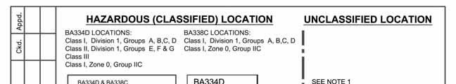
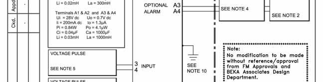
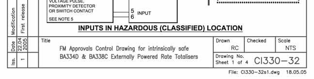
34 34
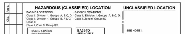
35 35
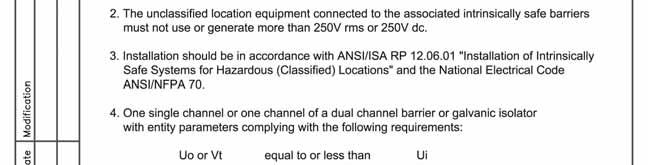
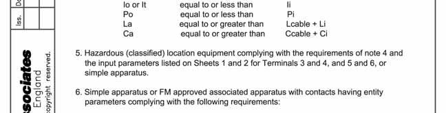
36 36
37 37
38 38
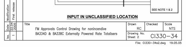
39 39
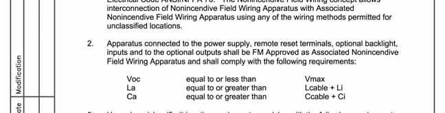
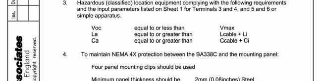
40 40
BA334D Intrinsically safe Externally powered pulse input field mounting rate totaliser Issue 13
 TR Automatyka Sp. z o. o. Tel. (+48 022) 886 10 16 www.trautomatyka.pl ul. Lechicka 14 ; 02-156 Warszawa Fax. (+48 022) 846 50 37 biuro@trautomatyka.pl BA334D Intrinsically safe Externally powered pulse
BA374C Intrinsically safe field mounting indicating temperature transmitter
 BA374C Intrinsically safe field mounting indicating temperature transmitter Issue: 5 3rd December 2003 CONTENTS 1. Description 2. Operation 2.1 Controls 3. Intrinsic Safety Certification 3.1 ATEX certificate
BA554D 4/20mA loop-powered field mounting rate totaliser
 BA554D 4/20mA loop-powered field mounting rate totaliser Issue: 1 September 2000 2 CONTNTS 1. Description 2. Operation 2.1 Controls 2.2 Displays 3. System Design 3.1 Flow transmitter loops 3.2 Remote indication
BA307E, BA327E, BA308E & BA328E intrinsically safe loop-powered panel mounting indicators Issue 6
 BA307E, BA327E, BA308E & BA328E intrinsically safe loop-powered panel mounting indicators Issue 6 Issue: 6 23 rd September 2013 2 CONTENTS 1. Description 2. Operation 2.1 Controls 3. Intrinsic safety certification
BA488CF Intrinsically safe Panel mounting Fieldbus Display
 BA488CF Intrinsically safe Panel mounting Fieldbus Display Issue: 8 Issue: 8 8 th May 2006 2 CONTENTS 1. Description 1.1 Documentation 1.2 Version 2.0 firmware 2. Operation 2.1 Controls 3. Intrinsic Safety
4) Intrinsic Safety Certification
 Intrinsic Safety Certification") INSTRUCTION MANUAL Minialert Intrinsically Safe Round Combined Unit Section Volume Control Tone Generator S2 S3 Tone Selection Switches Fig 1 Simplified block diagram The combined unit is CE marked for
INSTRUCTION MANUAL Minialert Intrinsically Safe Round Combined Unit Section Volume Control Tone Generator S2 S3 Tone Selection Switches Fig 1 Simplified block diagram The combined unit is CE marked for
INSTRUCTION MANUAL IS-mB1 Minialite Intrinsically Safe Round LED Beacon
 INSTRUCTION MANUAL Minialite Intrinsically Safe Round LED This instruction sheet describes installations which conform to EN60079:Part14:2008 Electrical Installation in Hazardous Areas. When designing
INSTRUCTION MANUAL (ATEX)
") INSTRUCTION MANUAL (ATEX) ISmA1M Minialarm Intrinsically Safe Round ISmA1M Volume Control Tone Generator S3 Tone Selection Switches Fig 1 Simplified block diagram The ISmA1M sounder is CE marked for compliance
INSTRUCTION MANUAL (ATEX) ISmA1M Minialarm Intrinsically Safe Round ISmA1M Volume Control Tone Generator S3 Tone Selection Switches Fig 1 Simplified block diagram The ISmA1M sounder is CE marked for compliance
DB5 Intrinsically Safe Sounder Type DB-5
 Operating Instructions RTK Instruments Limited DB5 Intrinsically Safe Sounder Type DB-5 Description The DB5 Sounder is a strong, lightweight warning sounder, CENELEC certified to Ex II 1G EExia IIC T4
Software Version 2.01 LEVEL MONITOR MODEL 220
 Software Version 2.01 LEVEL MONITOR MODEL 220 19 April 2000 CONTENTS 1. Introduction 1 1.1 Model Number Designation 2 1.2 Intrinsic Safety Considerations 3 2. Specification 4 3. Operation 6 3.1 Display
E2S Datasheet v10a. The IS-mA1 is suitable for all intrinsically safe signalling applications including fire, security and process control.
 E2S Datasheet 1.2.1 v10a ISmA1 ISminialarm The ISmA1 is a compact, 100dB(A) alarm sounder. Approvals include ATEX, IECEx and GOSTR for Zone 0 applications and FM approval for Class I Division 1 and Class
RTK Instruments Limited St James Business Park, Knaresborough, North Yorkshire, England. HG5 8PJ
 Operating Instructions RTK Instruments Limited Telephone: 44 (0)1423 580500 Facsimile: 44 (0)1423 580501 DA135 Intrinsically Safe LED Beacon Introduction This manual provides the information necessary
Model 144H. Product Data Sheet , Rev DB February Content
 Rosemount 144 PC-Programmable Temperature Transmitter Provides an installation-ready solution for temperature monitoring applications using Complete Point Solutions (CPS) Increases measurement accuracy
Model 144H. Product Data Sheet , Rev DB February Content
 Rosemount 144 PC-Programmable Temperature Transmitter Provides an installation-ready solution for temperature monitoring applications using Complete Point Solutions (CPS) Increases measurement accuracy
OilSET Installation and Operating Instructions. Oil Separator Alarm Device with SET/DM3AL sensor
 Labkotec UK Ltd Adminicle House 1 Lumb Lane Audenshaw Manchester M34 5WH GREAT BRITAIN Tel: 0844 3350 477 Fax: 0161 4281 179 E-mail: info@labkotec.co.uk 10.8.2012 Internet: www.labkotec.co.uk 1/13 OilSET-1000
SET Installation and Operating Instructions. Level switch for one sensor
 Labkotec Oy Myllyhaantie 6 FI-33960 PIRKKALA FINLAND Tel.: +358 29 006 260 Fax: +358 29 006 1260 7.11.2013 Internet: www.labkotec.fi 1/14 SET-1000 Level switch for one sensor Copyright 2013 Labkotec Oy
SBEx-4 BISTATE SEPARATOR 1, 2, 3 or 4 channels in rail housing (TS35, 22,5mm width)
") SBEx-4 BISTATE SEPARATOR,, 3 or 4 channels in rail housing (TS3,,mm width) - group I category (M), group II and III category () accompanying device, - intrinsically safe input circuits with ia protection
SBEx-4 BISTATE SEPARATOR,, 3 or 4 channels in rail housing (TS3,,mm width) - group I category (M), group II and III category () accompanying device, - intrinsically safe input circuits with ia protection
Technical Data. Dimensions
 0102 Model Number Features 8 mm non-flush Stainless steel housing Usable up to SIL2 acc. to IEC 61508 Technical Data specifications Switching element function NAMUR, NC Rated operating distance s n 8 mm
L+T GASETECHNIK. Klöpper-Waldmann GmbH & Co. K G. Alarm unit LSG4
 Areas of application The LSG4 alarm unit is used for monitoring industrial systems, e.g. in the following areas: Alarm and hazard stati in production e.g. for monitoring temperature and pressure in reactors
E2S Datasheet v10a
 E2S Datasheet 1.2.3 v10a ISmC1 ISminialert The ISmC1 is a compact combined 100dB(A) alarm sounder and L.E.D. beacon only one Zener barrier or galvanic isolator required to run both sounder & beacon or
Operating Instructions Edition 02/2007
 Operating Instructions Edition 02/2007 Temperature Transmitter 7NG3214 with PROFIBUS PA 7NG3215 with FOUNDATION Fieldbus sitrans Introduction 1 General safety notes 2 SITRANS T Temperature transmitter
INSTRUCTION MANUAL. SIL 3 - SIL 2 IIB Group Power Supply for Hazardous Area Equipment DIN-Rail Model PSD1001C PSD1001C
 PSD1001C INSTRUCTION MANUAL SIL 3 SIL 2 IIB Group Power Supply for Hazardous Area Equipment DINRail Model PSD1001C PSD1001C SIL 3 SIL 2 IIB Group Power Supply for hazardous Area Equipment ISM006510 General
Technical Data. General specifications. Rated operating distance s n 5 mm
 0102 Model Number Features 5 mm non-flush Usable up to SIL 2 acc. to IEC 61508 Technical Data specifications Switching function Normally closed (NC) Output type NAMUR Rated operating distance s n 5 mm
RT FLOW RATE TOTALISER
 Universal Mount Series RT FLOW RATE TOTALISER I N S T R U C T I O N M A N U A L S U P P L E M E N T for I N T R I N S I C A L L Y S A F E F L O W R A T E T O T A L I S E R ATEX & IECEx approvals The name
AM54. Armored Variable Area Flowmeter Series AM54331/32 Series AM54371/72/73/74 Series AM54431/32 Series AM54471/72/73/74
 AM54 Instruction Bulletin North American Installation Addendum Document Number PN25016 Armored Variable Area Flowmeter Series AM54331/32 Series AM54371/72/73/74 Series AM54431/32 Series AM54471/72/73/74
Inductive slot sensor
 0102 Model Number Features 2 mm slot width Technical Data specifications Switching function Normally closed (NC) Output type NAMUR Slot width 2 mm Depth of immersion (lateral) 5... 7 mm, typ. 6 mm Output
SET-2000 Oil/Sludge 12 VDC
 Labkotec Oy Myllyhaantie 6 FI-33960 PIRKKALA FINLAND Tel: + 358 29 006 260 Fax: + 358 29 006 1260 12.2.2015 Internet: www.labkotec.fi 1/14 SET-2000 Oil/Sludge 12 VDC Alarm Device for Oil Separators with
Intrinsically Safe Flame Detector Installation Guide
 This document is IS Installation Guide/00/Issue 3 Intrinsically Safe Installation Guide General This Installation Guide gives information on the intrinsically safe (I.S.) version of the flame detectors
EU DECLARATION OF CONFORMITY
 The Low Voltage Directive (LVD) 2014/35/EU and Electromagnetic Compatibility (EMC) Directive 2014/30/EU. Capacitive level sensor DLS 27N(T) Capacitive level sensor type DLS 27N(T) is designed to bistable
Technical Data. General specifications Switching element function DC Dual NC Rated operating distance s n 3 mm
 0102 Model Number Features Direct mounting on standard actuators EC-Type Examination Certificate TÜV99 ATEX 1479X Accessories BT32 BT32XS BT32XAS BT33 BT34 V1-G-N4-5M-PUR Female cordset, M12, 4-pin, NAMUR,
PEPPERL+FUCHS GmbH
 Comfort series 1.5 mm embeddable M8x1 4 25 16 13 LED Switching element function NAMUR NC Rated operating distance s n 1,5 mm Installation embeddable Assured operating distance s a 0... 1,215 mm Reduction
SET-2000 Hi Level/Oil
 Labkotec Oy Labkotie 1 FI-36240 KANGASALA FINLAND Tel: + 358 29 006 260 Fax: + 358 29 006 1260 13.03.2008 Internet: www.labkotec.fi Alarm Device for Oil Separators Copyright 2008 Labkotec Oy We reserve
Technical Data. General specifications Switching element function Rated operating distance s n 5 mm
 0102 Model Number Features 5 mm non-flush Usable up to SIL2 acc. to IEC 61508 Technical Data specifications Switching element function NAMUR, NC Rated operating distance s n 5 mm Installation non-flush
OilSET-1000 (12 VDC)
") Labkotec Oy Myllyhaantie 6 FI-33960 PIRKKALA FINLAND Tel: +358 29 006 260 Fax: +358 29 006 1260 Internet: www.labkotec.fi 20.03.2009 1/11 OilSET-1000 (12 VDC) Oil Separator Alarm Device Copyright 2009
Labkotec Oy Myllyhaantie 6 FI-33960 PIRKKALA FINLAND Tel: +358 29 006 260 Fax: +358 29 006 1260 Internet: www.labkotec.fi 20.03.2009 1/11 OilSET-1000 (12 VDC) Oil Separator Alarm Device Copyright 2009
U L T R A S O N I C G A S L E A K D E T E C T O R
 U L T R A S O N I C G A S L E A K D E T E C T O R GasSonic Surveyor ultrasonic gas leak detector APPLICATIONS (EXAMPLES) Offshore and Onshore Oil and Gas Installations Petrochemical Processing Plants Gas
Sierra Model 951 Digital Flo-Box. Instruction Manual Part Number IM-951 Revision A 09-05
 Sierra Model 951 Digital Flo-Box Instruction Manual Part Number IM-951 Revision A 09-05 5 Harris Court, Building L Monterey, CA 93940 (831) 373-0200 (800) 866-0200 Fax (831) 373-4402 www.sierrainstruments.com
Fisher LCP100 Local Control Panel
 Instruction Manual LCP100 Local Control Panel Fisher LCP100 Local Control Panel Contents Introduction... 1 Scope of Manual... 1 Description... 2 Specifications... 2 Installation... 3 Hazardous Area Classifications
Ex Long & Short stroke LPI POSITION TRANSMITTER MKII For linear position measurement in compressors
 Instructions manual Ex Long & Short stroke LPI POSITION TRANSMITTER MKII For linear position measurement in compressors HB Products A/S Bøgekildevej 21 DK8361 Hasselager support@hbproducts.dk www.hbproducts.dk
INSTRUCTION MANUAL (ATEX/IECEx/SIL2) BExBG05D-SIL Flameproof Xenon SIL 2 Beacons For use in Flammable Gas and Dust Atmospheres
 BExBG05D-SIL Flameproof Xenon SIL 2 Beacons For use in Flammable Gas and Dust Atmospheres") INSTRUCTION MANUAL (ATEX/IECEx/SIL2) BExBG05D-SIL Flameproof Xenon SIL 2 Beacons For use in Flammable Gas and Dust Atmospheres 1) Introduction The BExBG05D-SIL is a flameproof beacon which is certified
INSTRUCTION MANUAL (ATEX/IECEx/SIL2) BExBG05D-SIL Flameproof Xenon SIL 2 Beacons For use in Flammable Gas and Dust Atmospheres 1) Introduction The BExBG05D-SIL is a flameproof beacon which is certified
INSTRUCTION MANUAL. Frequency-Pulse Converter, Repeater and Trip Amplifiers Din-Rail Model D1060S D1060S
 D1060S INSTRUCTION MANUAL FrequencyPulse Converter, Repeater and Trip Amplifiers DinRail Model D1060S D1060 Frequency Pulse Converter, Repeater and Trip Amplifiers ISM005411 Characteristics General Description:
Fire & Security Products. Siemens Building Technologies Group
 Fire & Security Products Siemens Building Technologies Group . 1 Brief overview.................................................... 1 1.1 Characteristics....................................................
SET-2000 Oil/Sludge. Alarm Device for Oil Separators. Installation and Operating Instructions
 SET-000 Oil/Sludge Alarm Device for Oil Separators Copyright 007 Labkotec Oy We reserve the right for changes without notice TABLE OF CONTENTS GENERAL... INSTALLATION... 4. SET-000 Oil/Sludge Control Unit...
DP-500. Target Flowmeter. Flow measurement of Gases and Liquids. Instrumentation for fluids
 UK / Europe Office Tel: +44 (0)8700 434040 Fax: +44 (0)8700 434045 info@omniinstruments.co.uk www.omniinstruments.co.uk Australia / Asia Pacific Office Tel +61 (0)282 442 363 Fax +61 (0)294 751 278 info@omniinstruments.com.au
OilSET Installation and Operating Instructions. Oil Separator Alarm Device
 Labkotec Oy Myllyhaantie 6 FI-33960 PIRKKALA FINLAND Tel: +358 29 006 260 Fax: +358 29 006 1260 18.11.2010 Internet: www.labkotec.fi 1/10 OilSET-1000 Oil Separator Alarm Device Copyright 2010 Labkotec
Technical Data. Dimensions
 0102 Model Number Features 5 mm flush Usable up to SIL2 acc. to IEC 61508 Accessories EXG-18 Quick mounting bracket with dead stop BF 18 Mounting flange, 18 mm Technical Data specifications Switching element
REGARD. REGARD 4-20 AND Ex CHANNEL CARDS INSTALLATION AND OPERATING MANUAL (FOR ATEX VERSION CARDS)
") REGARD REGARD 4-20 AND Ex CHANNEL CARDS INSTALLATION AND OPERATING MANUAL (FOR ATEX VERSION CARDS) Part No. 4206712 For use with Regard 4-20 and Ex cards software version 3.0 or later. Draeger Safety UK
REGARD REGARD 4-20 AND Ex CHANNEL CARDS INSTALLATION AND OPERATING MANUAL (FOR ATEX VERSION CARDS) Part No. 4206712 For use with Regard 4-20 and Ex cards software version 3.0 or later. Draeger Safety UK
DSF xx15.xx xhv Ex-Atex Ex-Atex Certified Two wire Hall Effect Speed Sensor
 DSF xx15.xx xhv Ex-Atex Product ID Type # Product # Drawing # DSF 1215.01 SHV Ex-atex (5m) 304Z-05197 113216 DSF 1415.01 AHV Ex-atex S148 304Z-05256 113351 DSF 1615.01 SHV Ex-atex (5m) 304Z-05196 113214
Annubar Flowmeter Series
 Reference Manual Appendix B Approvals Annubar Flowmeter Series Hazardous Locations Installations.................. page B-1 Rosemount 3051SFA Product Certifications.......... page B-1 Rosemount 3095MFA
VERSAFLOW VORTEX Supplementary instructions
 VERSAFLOW VORTEX Supplementary instructions Vortex flowmeter Equipment category II 2G CONTENTS VERSAFLOW VORTEX 1 Safety instructions 3 1.1 General notes... 3 1.2 EC conformity... 3 1.3 Approval according
RS Pro Infrared Temperature Sensor
 Instruction Manual RS Pro Infrared Temperature Sensor Stock Number: 161-8103 Introduction The RS Pro Infrared Temperature Sensor is a device for measuring the temperature of the surface of a solid or liquid
Technical Data. General specifications Switching element function Rated operating distance s n 5 mm
 0102 Model Number Features 5 mm flush Usable up to SIL 3 acc. to IEC 61508 Application Danger! In safety-related applications the sensor must be operated with a qualified fail safe interface from Pepperl+Fuchs,
OSA 3. Level alarm for oil separator. Afriso Ema AB. Kilvägen 2 SE Arlöv Sweden T +46-(0) F +46-(0)
 F +46-(0)") Level alarm for oil separator CONTENTS: Functional description... 2 Component parts... 3 Spare parts... 5 Safety regulations... 6 Checklist... 7 Installation... 8 Commissioning... 11 Operation... 14 Maintenance...
Level alarm for oil separator CONTENTS: Functional description... 2 Component parts... 3 Spare parts... 5 Safety regulations... 6 Checklist... 7 Installation... 8 Commissioning... 11 Operation... 14 Maintenance...
INSTRUCTION MANUAL. SIL 2 Load Cell/Strain Gauge Bridge Isolating Converter DIN-Rail Power Bus and Termination Board Model D5264S D5264S
 D5264S INSTRUCTION MANUAL SIL 2 Load Cell/Strain Gauge Bridge Isolating Converter DIN-Rail Power Bus and Termination Board Model D5264S Characteristics General Description: The single channel DIN Rail
Air Sensor. SAC Ex FCS Ex. Manual ATEX. AQ M-Tech AB
 Air Sensor SAC Ex FCS Ex Manual AQ M-Tech AB ATEX Air Sensor SAC Ex FCS Ex ATEX Certified AQ M-Tech AB Manual version 2.2 February 2017 2 Air Sensor Manual for SAC Ex and FCS Ex Table of contents 1. Manufacturer
This document is a preview generated by EVS
 EESTI STANDARD EVS-EN 12261:2002 Gas meters -Turbine gas meters Gas meters -Turbine gas meters EESTI STANDARDIKESKUS EESTI STANDARDI EESSÕNA NATIONAL FOREWORD Käesolev Eesti standard EVS-EN 12261:2002
SITRANS T. SITRANS T Explosion protected temperature sensor. General information. Marking of the degree of protection. Range of uses.
 General information 1 Marking of the degree of protection 2 SITRANS T SITRANS T Explosion protected temperature sensor Operating Instructions Range of uses 3 Installation 4 Assembly and disassembly 5 Commissioning
AO Annunciator Module
 General Specifications GS48C43Z01-00E-N AO-543-01 Annunciator Module GENERAL Figure 1 This module has two independent annunciator circuits. The circuits handle fault signals and operator actions (acknowledge,
Analog Room Pressure Monitor RPC Series
 Description The Room Pressure Monitor is used to measure differential pressure in the range of 0.125 to 1"wc or 30 to 250 Pa. It combines precision high sensitivity silicon sensing capabilities and the
1X-F Series Installation Manual
 1X-F Series Installation Manual P/N 501-415003-1-31 REV 03.10 ISS 13NOV13 Copyright Trademarks and patents Manufacturer Version Certification European Union directives Contact information 2013 UTC Fire
Intrinsically Safe Solutions
 Intrinsically Safe Solutions INSTALLATION MANUAL 04/12/14 Rev D DOC-01-029 Documentation Feedback Your feedback helps us keep our documentation up to date and accurate. If you have any comments or suggestions
DP-500. Target Flowmeter. Flow measurement of Gases and Liquids. Instrumentation for fluids
 Instrumentation for fluids Target Flowmeter Series DP-65 DP-500 Flow measurement of Gases and Liquids Metallic construction. Operates horizontally or vertically DN-80 to DN-500 Flow rate: - Water: 1.5
Additional Operating Instructions SITRANS F. Vortex flowmeters. SITRANS FX330 Ex-i.
 Additional Operating Instructions SITRANS F Vortex flowmeters Ex-i Edition 09/2018 CONTENTS 1 Safety instructions 3 1.1 General notes... 3 1.2 EU conformity... 3 1.3 Approval according to the IECEx scheme...
Gas cylinder scale Model GCS-1
 Electronic pressure measurement Gas cylinder scale Model GCS-1 WIKA data sheet PE 87.19 Applications Level measurement of liquid gases in gas cabinets and gas distribution systems Level measurement in
PRODUCT CONFORMITY CERTIFICATE
 PRODUCT CONFORMITY CERTIFICATE HydroRanger 200 Controller (segmented display or HMI display) with Echomax XRS-5 ultrasonic level transducer manufactured by: Siemens Canada Ltd. Siemens Milltronics Process
MAINS KLARGESTER SEPARATOR ALARM INSTALLATION & OPERATIONS MANUAL
 MAINS KLARGESTER SEPARATOR ALARM INSTALLATION & OPERATIONS MANUAL Contents IMPORTANT... 3 General Description... 4 General Operation... 4 Changing Factory Settings... 4 Alarm Type... 4 Check Interval...
LC2200 Level Controller Installation and Maintenance Instructions
 4025250/9 IM-P402-77 AB Issue 9 LC2200 Level Controller Installation and Maintenance Instructions LC2200 ALARM TEST >50% >100%
RADAR LEVEL GAUGE SPECIAL SAFETY INSTRUCTION
 Special Safety Instruction en RADAR LEVEL GAUGE SPECIAL SAFETY INSTRUCTION Contents TankRadar Pro European ATEX Directive Information............................... 2 ATEX marking and Ex Certification
Analox 1000 Series. User Manual. Analox Sensor Technology Ltd. 15 Ellerbeck Court, Stokesley Business Park North Yorkshire, TS9 5PT, UK
 Analox 1000 Series User Manual Analox Sensor Technology Ltd. 15 Ellerbeck Court, Stokesley Business Park North Yorkshire, TS9 5PT, UK T: +44 (0)1642 711400 F: +44 (0)1642 713900 W: www.analox.net E: info@analox.net
Technical Data. General specifications Switching element function Rated operating distance s n 8 mm
 0102 Model Number Features 8 mm non-flush Usable up to SIL 3 acc. to IEC 61508 Application Danger! In safety-related applications the sensor must be operated with a qualified fail safe interface from Pepperl+Fuchs,
DSF xx10.xx xhv Ex-Atex Hall Effect Single Channel Speed Sensor
 Product ID Type # Product # Drawing # DSF 1210.00 SHV Ex-atex (2m) 374Z-05066 110428F1 DSF 1210.00 SHV Ex-atex (5m) 374Z-05176 110428F1 DSF 1210.00 SHV Ex-atex (10m) 374Z-05590 110428F1 DSF 1410.00 SHV
Technical Data. General specifications Switching element function Rated operating distance s n 4 mm
 0102 Model Number Features 4 mm non-flush Accessories BF 12 Mounting flange, 12 mm Technical Data specifications Switching element function NAMUR, NO Rated operating distance s n 4 mm Installation non-flush
IECEx Certificate of Conformity
 Page 1 of 10 IECEx Certificate of Conformity INTERNATIONAL ELECTROTECHNICAL COMMISSION IEC Certification Scheme for Explosive Atmospheres for rules and details of the IECEx Scheme visit www.iecex.com Certificate
Speed and Frequency Seite 1 von 7
 Speed and Frequency Seite 1 von 7 E16 Systems for High Safety Speed ing, all with Triple Modular Redundancy. A choice of versions to meet various demands. Compliant with SIL3 / IEC 61508 and/or API 670.
YTA Series Temperature Transmitters [Style: S3] EN :2006, -11:2007, -26:2007. Supply circuit: Ui=30 V, Ii=165 ma,
![YTA Series Temperature Transmitters [Style: S3] EN :2006, -11:2007, -26:2007. Supply circuit: Ui=30 V, Ii=165 ma,](/thumbs/89/98785336.jpg "YTA Series Temperature Transmitters [Style: S3] EN :2006, -11:2007, -26:2007. Supply circuit: Ui=30 V, Ii=165 ma,") User s Manual YTA Series Temperature Transmitters [Style: S3] Manual Change No. 10-008 Please use the attached sheets in the following manuals when the product is with /KU2 option and EN60000 Series based
User s Manual YTA Series Temperature Transmitters [Style: S3] Manual Change No. 10-008 Please use the attached sheets in the following manuals when the product is with /KU2 option and EN60000 Series based
Supplementary Installation and Operating Instructions. Category II2G
 Supplementary Installation and Operating Instructions Flap-type Flow Meter Category II2G 2 Contents 1. General safety directions...3 2. Main safety-relevant characteristics...4 2.1. Category / Zone...4
Declaration of conformity
 File: ATEX Manoswitch DoC 2017-10-20 Rev: 2017-10-20 id: mk Declaration of conformity The products listed in Appendix B, meet the requirements for a simple apparatus given by the standards listed below.
Battery Powered Separator Alarm Type Standalone Unit. Installation, Operation & Maintenance
 Battery Powered Separator Alarm Type 17200 Standalone Unit Installation, Operation & Maintenance Battery Powered Separator Alarm Type 17200 Contents Declaration of Conformity 3 IMPORTANT 3 General Description
EC3-X33 Stand-alone Superheat Controller
 is a stand-alone universal superheat controller for air conditioning, refrigeration and industrial applications such as chillers, industrial process cooling, rooftops, heat pumps, package unit, close control,
Process Alarm Module RTA 421
 Technical Information TI 074R/24/ae Process Alarm Module RTA 421 Alarm module and power supply for monitoring current or voltage signals Application Areas Plant and machine construction Panel builders
SCHMIDT LED Measured Value Display MD Instructions for Use
 SCHMIDT LED Measured Value Display MD 10.010 Instructions for Use Table of Contents 1 Important Information... 3 2 Application range... 4 3 Mounting instructions... 4 4 Electrical connection... 6 5 Signalizations...
14300 MAINS SEPARATOR ALARM MANUAL
 Conder Environmental Solutions 14300 MAINS SEPARATOR ALARM MANUAL Separator and Alarm provided by: Alarm Installation, Commissioning & Servicing Support Please contact: www.envirotank.com.au www.envirotank.co.nz
DIESEL ENGINE CONTROL UNIT DCU USER S MANUAL - N-2000 Lillestrøm, Norway Tel: (+47) Fax: (+47)
 Fax: (+47)") DIESEL ENGINE CONTROL UNIT DCU 205 - USER S MANUAL - N-2000 Lillestrøm, Norway Tel: (+47) 64 84 52 00 Fax: (+47) 64 84 52 12 office@auto-maskin.no - 1 - TABLE OF CONTENTS 1. INTRODUCTION TO THE DCU 205...4
DIESEL ENGINE CONTROL UNIT DCU 205 - USER S MANUAL - N-2000 Lillestrøm, Norway Tel: (+47) 64 84 52 00 Fax: (+47) 64 84 52 12 office@auto-maskin.no - 1 - TABLE OF CONTENTS 1. INTRODUCTION TO THE DCU 205...4
Two-Channel Gas Controller
 Two-Channel Gas Controller Specifications subject to change without notice. USA 09 Page of DESCRIPTION Highly configurable, UL 0 performance-tested and -certified, and wall-mounted gas monitor; continuously
ST Wiring diagram. Product description. Standard temperature controller. Order number
 ST64-31.10 Standard temperature controller Order number 900197.007 Old Id.Nr.: 386169 Wiring diagram Product description The controller ST64-31.10 was developed for simple thermostatic controls. The round
Intrinsically Safe, NEMA 4, Type 4X, IP67 Loop-Powered Meter
 PD685 Intrinsically Safe, NEMA 4, Type 4X, IP67 Loop-Powered Meter Actual Size Digits C US Intrinsically Safe 3½ Digits LARGE DISPLAY NEMA 4, Type 4X, IP67 Loop-Powered Field-Mount Process Meter 4-20 ma
Installation, Operating and Maintenance Manual
 STATUS ZONES CONTROLS FIRE FAULT DISABLED FIRE 1 2 3 4 5 6 7 8 TEST FAULT DISABLED 1 5 BUZZER SILENCE RESET 1 2 TEST 2 6 LAMP TEST 3 SUPPLY 3 7 SYSTEM FAULT 4 8 SOUNDERS ACTIVATE/ SILENCE 4 FAULTS INSTRUCTIONS
Technical Data. Dimensions
 0102 Model Number Features 15 mm non-flush Technical Data specifications Switching element function NAMUR, NC Rated operating distance s n 15 mm Installation non-flush Assured operating distance s a 0...
Technical Data. Dimensions
 0102 Model Number Features Comfort series 50 mm non-flush Technical Data specifications Switching element function NAMUR, NC Rated operating distance s n 50 mm Installation non-flush Output polarity NAMUR
PROFIBUS-PA Display RID 261 PROFIBUS-PA
 Technical Information TI 071R/09/en Mat.-Nr.: 510 01194 PROFIBUS-PA Display RID 261 PROFIBUS-PA Display of process values and set point alarms on PROFIBUS-PA systems R Applications Direct connection to
USER GUIDE FOR GASSONIC SURVEYOR ULTRASONIC GAS LEAK DETECTOR
 T E C H N I C A L D O C U M E N T A T I O N USER GUIDE FOR GASSONIC SURVEYOR ULTRASONIC GAS LEAK DETECTOR CONTENTS 1.0 The Gassonic Surveyor....................................... 3 1.1 Application..............................................
ED820-24V MODEL INSTRUCTION MANUAL. fire DETECTOR
 ED820 24V MODEL fire DETECTOR INSTRUCTION MANUAL Address: Enigma House, Enigma Business Park, Malvern, Worcestershire, WR14 1GD Tel: 44 (0)1684 891500 Fax: 44 (0)1684 891600 Email: sales@electronicdevices.co.uk
DIGITAL METERS Large Display Temperature Meters Instruction Manual
 DIGITAL METERS Large Display Temperature Meters PD755 PD756 PD757 Handles Thermocouple & RTD Inputs with Simplicity J, K, T, E, R, & S Thermocouples 100 Ω Platinum RTD (0.00385 or 0.00392 curve) Large
Ramsey Series Motion Monitoring Systems Accurate Sensing of Speed Conditions on Rotating Shafts and Machinery
 Ramsey Series 60-200 Motion Monitoring Systems Accurate Sensing of Speed Conditions on Rotating Shafts and Machinery Ramsey Series 60-200 Motion Monitoring Systems offer versatile and reliable packages
Tachometer/Hourmeter/Trip. Installation and Operation Manual
 3211 Fruitland Ave Los Angeles, CA 90058 MTH-103E Tachometer/Hourmeter/Trip Installation and Operation Manual Rev. G P/N 145F-13048 PCO - 00010525 Copyright 2014-2017, Barksdale Inc. All Rights Reserved
5.1 Safety instructions for system configuration and explosion protection. Zone-specific conditions for system configuration
 Planning and configuration of the I.S. 1 system 5 ENGINEERING 5.1 Safety instructions for system configuration and explosion protection During engineering, comply with the guidelines set out in EN 60 079-14.
Nitrogen Dioxide (NO2) Single-Point Gas Detection System
 Single-Point Gas Detection System") Nitrogen Dioxide (NO) Single-Point Gas Detection System DESCRIPTION Wall-mounted gas monitor with built-in nitrogen dioxide (NO)/diesel fume gas sensor, accepts one analog remote device such as a secondary
Nitrogen Dioxide (NO) Single-Point Gas Detection System DESCRIPTION Wall-mounted gas monitor with built-in nitrogen dioxide (NO)/diesel fume gas sensor, accepts one analog remote device such as a secondary
Optical Smoke Detector Heat Detector Manual Call Point Output Unit Isolator
 TECHNICAL GUIDE Optical Smoke Detector Heat Detector Manual Call Point Output Unit Isolator The XPlorer Range XPlorer is a new range of analogue addressable detectors and interfaces developed for all who
DICTATOR Hold-Open Systems for Hazardous Areas
 DICTATOR for Hazardous Areas Products to be used in hazardous areas obviously have to meet special demands. The European ATEX directives (first the EN 94/9/EG and then the directive 2014/34/ EU) brought
PREMIER PLATINUM INFRARED GAS SENSOR
 PREMIER PLATINUM INFRARED GAS SENSOR LOW POWER VERSION DUAL HYDROCARBONS AND CARBON DIOXIDE SENSOR Exd Certified VERSIONS *** Available in EN50271 / SIL1 Certified versions *** Technical data sheet TDS0150
ANALOX SENSOR TECHNOLOGY LTD ANALOX DD1101 INSTALLATION & OPERATION MANUAL
 ANALOX SENSOR TECHNOLOGY LTD ANALOX DD1101 INSTALLATION & OPERATION MANUAL SAFETY WARNING Please Refer to the Safety Warning in Section 7.1 regarding the chemicals in the oxygen sensor Analox Sensor Technology