Temperature-Relay TR210
|
|
|
- Deborah Black
- 5 years ago
- Views:
Transcription


1 Operating instructions Temperature-Relay TR210 Page 1 of 24
2 Table of contents 1. Application and Short description Overview of functions Connection Plan Display and operation parts Programs Important Information Installation Putting into operation Display mode Menu mode (Decimal point behind the last digit ON) Parameter setting mode (Decimal point behind the last digit FLASHES) Operation Program Program Program Program Program Program Program Program Program Action chart Factory setting Error search and measures Technical data Housing Design V Page 2 of 24
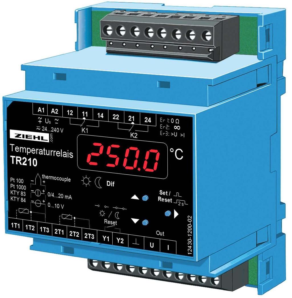
3 1. Application and Short description Control units type TR210 control up to 2 limit values. The TR210 is used as: General temperature protection of machines and installations Temperature control unit, also for cooling applications Difference temperature controller unit for air-conditioning technology 2. Overview of functions 2 Sensor inputs: Pt 100, Pt 1000, KTY 83 or KTY 84 in 2- or 3-wire configuration Thermocouples Type B, E, J, K, L, N, R, S, T Input signal DC 0-10 V; DC 0/4-20 ma 0.1 C resolution between C 2 Relay outputs (each 1 change-over contact) 1 Analogue output DC 0-10 V or 0/4-20 ma for parameterizing (not potentially separated from the inputs) Universal power supply AC/DC V Several selectable programs Storage and indication of the measured MIN- und MAX-values pluggable terminals 3. Connection Plan Page 3 of 24
4 4. Display and operation parts 1, 3 LEDs state of relay 2 Digital display, 4 digits 4, 5 LEDs day/night switching 6 LED measuring of differences 7 Up pushbutton 8 Pushbutton set/reset 9 Down pushbutton 10, 11 LEDs sensor 5. Programs 9 programs (Pr ) with factory default settings can be selected. Due to these programs, the device can be adapted very easily to the application. Choose the program, which fits to your application and after that change the parameters! In case of changing the program, each parameter is being reset to "factory setting". (see chart " factory setting") Choosing the programs: When applying the power supply hold the pushbutton Set for 10 s. Then the program (Pr 1... Pr 9) can be selected with the pushbuttons up/down and confirmed with Set. Pr Input Limit value 1* 1 temperature sensor temperature sensors 1 per sensor 3 1 temperature sensor 2 day and 2 night 4 2 temperature sensors 1 day and 1 night per sensor 5 2 temperature sensors 2 difference temperature 6 1x 0-10 V or 0/ 4-20 ma 2 7 2x 0-10 V or 0/ 4-20 ma 1 per input 8 2x 0-10 V or 0/4-20 ma 2 difference 9 2 temperature sensors 2 MIN/MAX * factory setting Please note: Pr 1, 2, 5-9: Y1 / Y2 = remote reset (external) Pr 3+4: Y1 / Y2 = switching day / night 6. Important Information To use the equipment flawless and safe, transport and store properly, install and start professionally and operate as directed. Only let persons work with the equipment who are familiar with installation, start and use and who have appropriate qualification corresponding to their function. They must observe the contents of the instructions manual, the information which are written on the equipment and the relevant security instructions for the setting up and the use of electrical units. The equipment is built according to DIN / EN and checked and leave the plant according to Page 4 of 24
5 security in perfect condition. To keep this condition, observe the security instructions with the headline Attention in the instructions manual. Ignoring of the security instructions may lead to death, physical injury or damage of the equipment itself and of other apparatus and equipment. If, in any case the information in the instructions manual is not sufficient, please contact our company or the responsible representative. Instead of the industrial norms and regulations written in this instructions manual valid for Europe, you must observe out of their geographical scope the valid and relevant regulations of the corresponding country. DANGER! Hazardous voltage! Will cause death or serious injury. Turn off and lock out all power supplying this device before working on this device. Observe the maximum temperature permissible when installing in switching cabinet. Make sure sufficient space to other equipment or heat sources. If the cooling becomes more difficult e.g. through close proximity of apparatus with elevated surface temperature or hindrance of the cooling air, the tolerable environmental temperature is diminishing. Attention! Connecting the temperature sensors The temperature sensors are connected to the clamps 1T1, 1T2 and 1T3 and so on. These pluggable terminals have a special contact material and may only be used for the connection of the sensors. When connecting 2 thermocouples they must be isolated from each other. Attention! Universal power supply The unit is equipped with a universal power supply, that is suitable for DC- and AC-voltages. Before connecting the unit to the current, make sure that the allowed scope of voltage of the control voltage Us, written on the lateral type plate, corresponds to the supply voltage of the unit.! Attention! When all relays are programmed in operation current mode (=pick up at alarm), a loss of the supply voltage or an instrument failure can remain unidentified. When the relay is applied as control instrument, the operator must ensure, that this error is recognized by regular examinations. We recommend to program and accordingly evaluate at least one relay in the closed-circuit current mode. 7. Installation The unit can be installed as follows: Installation in switchgear cabinet on 35 mm mounting rail according to EN With screws M4 for installation on walls or panel. (additional latch included in delivery) Connection according to connection plan or type plate. Page 5 of 24
6 ! A circuit-breaker or switch must be situated within easy reach of the unit and fused. Installation excess current protection should be 10 A. 8. Putting into operation Decimal point behind the last digit: Off = display mode, displays values of measuring inputs On = menu mode, select the menu items blinking = parameter setting mode 8.1 Display mode Indication of the current sensor temperature. The temperature is shown in degrees centigrade. The indication for voltage (0-10 V) and current (0/4-20 ma) can be scaled. LED relay (K1, K2) ON = relay picked up LED sensor ON = appropriate value in the display flashes = sensor error Function of buttons UP/DOWN Push short change into menu mode Push for > 2 s Function button SET/RESET Push short two sensors Display of the stored MIN- or MAXvalues of the chosen sensor Display sensor 1 / sensor 2 (/ difference) one sensor Display sensor / alarm limit 1 / alarm limit 2 Push for 2 s Reset restart interlock Push for 4 s Display of chosen program Push for 10 s Display of software version 8.2 Menu mode (Decimal point behind the last digit ON) Selection of the menu items for changing the parameters. In the menu items for sensorand alarm parameterizing the LEDs indicate the special classification sensor-alarmday/night - difference. Function button UP/DOWN Push short Selection of menu item; Change into display mode Function button SET/RESET Push short Change into parameter setting mode 8.3 Parameter setting mode (Decimal point behind the last digit FLASHES) LEDs indicate sensors and relays concerned by the selected parameter setting point as well as day/night-switching and differentiation measurement. Function button UP/DOWN Press short/long Function button SET/RESET Press short Adjustment of parameter value (slow/fast) Storage of setting and choice of next parameter. Change into menu mode after the last parameter Page 6 of 24
7 8.3.1 Parameterizing the sensors (S 1 / S 2): Dependent on the chosen program: temperature (Pr 1-5, 9) or current/voltage (Pr 6-8) Choose menu item with up/down until in indication S 1 and type of sensor alternate. Here it can be read clearly, which type of sensor is selected and on which alarm the sensor works (corresponding LEDs alarm on). Enter with Set in parameterizing sensor e.g. S 1 / 100 for Pt 100. Choose sensor type with up/down Set cable resistance or 3-wire configuration (3- L). 2-wire configuration, cable resistance compensation: Short-circuit the wires nearby the sensor and measure the cable resistance. Set parameter LA on this value. With 2-wire connection and a common wire for all sensors, all sensor measuring currents will be added on the common wire. The compensation value LA to be set is calculated as follows: LA = 3 x RL/2 (RL = resistance of two wires) We recommend 3-wire connection for each sensor Parameterizing of the alarms (AL 1 / AL 2): Choose menu item with up/down until AL 1 and limit (limit value) alternate in display, e.g. AL 1 und 130 for 130 C. Here it can be read clearly, which limit value is parameterized and to which sensor works on the alarm (yellow LEDs sensor on). Begin to parameterize with Set. Adjust limit with up/down. Adjust hysteresis. Negative hysteresis = MAX-switching point, the relay switches when the adjusted limit is reached and switches back when the signal is fallen by the hysteresis. E.g. limit 130 C and hysteresis -5 C: Relay switches at 130 C and switches back at 125 C. Positive hysteresis vice versa = MIN-switching point. Alarm delay time dal: An alarm is suppressed for the adjusted time, short-timed exceeding of the limit does not cause an alarm. Switch-back delay dof: An alarm is only switched off after the signal is below the limit and after delay of this time, e.g. a cooling ventilator can cool further on for this time to avoid, that it has to switch be switched on again after a short time. Function of relay: r -Closed-current circuit mode, relay is picked up in GOOD-state (=limit not reached) and releases when the limit is exceeded. Advantage: errors and faults normally cause an alarm. Disadvantage: alarm also when supply-voltage is switched off and after switching on until the relay has picked up. Unfavorable e.g. with transformers, particularly, when the supply-voltage of the TR210 comes from the monitored transformer. A-Operating-current mode: relay is released in GOOD state and picks up when the limit is exceeded. No alarm at errors and when supply-voltage switched off. Used normally switch ventilators or heatings or for tripping of transformers. r - L / A- L: alarm switches locked. Set back with reset only after fall short of the limit (with hysteresis) and end of the switch-back delay. Ready for Reset is indicated with A12L in the display mode. Error report: With Er r it can be selected, if the relay switches in the alarm state in case of sensor-error Er 1-9 (short circuit or break). (on / off) Page 7 of 24
8 8.3.3 Test relay (t St ): Here it can be programmed, that a relay switches into the alarm state after a certain time don, e.g. 1 weeks (= 168 hours) for the time dof, e.g. 10 s, to make a ventilator or a pump run for a short time, to make them move and protect the bearings from damage through long standstill. Choice of the alarm with up/down. Set switches to don and dof. don = off = test not active Sensor simulation (Si ): A sensor can be selected, and a measured temperature can be simulated with the buttons up/down. All functions of the unit work as if this temperature was really measured. If there is no button pushed for 15 minutes, the device automatically switches back into the display mode Sensor (CodE): After setting all parameters they can be protected by activating the code lock. After pushing Set, the display indicates Pi n. Adjust with buttons up/down Pi n 504 (factory setting). After pushing Set, code lock can be activated or switched off. After pushing Set again, an individual Pi n can be selected (write down). When code lock is activated all parameters can be seen but not be changed anymore. In case of problems with the code lock (forgotten Pi n) the lock can be switched off and the Pi n can be set back to 504, by pushing button set while connecting the device to supplyvoltage until Code / of F is indicated in the display Tips: - With the pre-set programs Pr 1 to Pr 9 the most important parameters can be set in advance, so that only little modifications are necessary, e.g. setting of the limits (limit values) for each alarm. - After finishing one menu item it is switched automatically on the next one. E.g. after programming the line resistance of sensor 1 and pushing Set, the devices switches on to sensor 2. - When the right decimal point in the 7 segment display is on, the display mode has been left, and the menu items can be chosen with up/down (menu mode). - When the right decimal point blinks, you are in the parameter setting mode and can change the setting with up/down. - Long pushing on up/down speeds up the changes in the display. - Pushing button up and down at the same time sets values to zero. - With reset (press set/reset for 2s) the display mode can be reached from every position (exception: simulation) of the parameter setting mode (the last selected value in is being stored). Page 8 of 24
9 8.3.7 Indication of the digital display: Pr 1... Pr 9 = program number A1, A2 = alarm 1 or alarm 2 active A12 = alarm 1 and alarm 2 active additional L = alarm locked, for setting back reset is necessary. S = sensor 100, 1000 = Pt 100, Pt , 84 = KTY-sensor 83, 84 LA = 2-wire cable resistance 3- L = 3-wire configuration Thermocouples (th..) Display t hb t he t hj t hk t hl t hn t hr t hs t ht Type B E J K L N R S T CoMP = compensation of the reference temperature of thermocouples i nt = internal reference temperature or fix reference temperature 0-10 = 0-10 V voltage input 0/4-20 = 0/4-20 ma current input SCAL = scaling of display for voltage- and current input Aut o = to adopt zero point, full scale and decimal point from the chosen type USEr = free scaling of zero point, full scale and decimal point = zero point value for 0 V, 0/4 ma,,,, = full scale value for 10 V, 20 ma dp = decimal point AL 1, AL 2 = alarm limit ALd = alarm limit day Al n = alarm night H = hysteresis dal = alarm delay (time delay until alarm) dof = switch back delay (time delay until alarm switches back to good) r EL = function of relay r, A = closed-circuit current mode, operating current mode r - L, A- L = closed-circuit- / operating current with interlocked switching (Locked) t st = relay test periodically in hours after the time don for the duration dof don = periodical time in hours for testing alarm/relay (off = no test) dof = duration of test E = exit (leave loop) ovt = analogue output: off, 0-10 V, 0-20 ma, 4-20mA SEn = sensor select for analogue output S12, = maximum value of sensor 1 or sensor 2 is put out S12_ = minimum value of sensor 1 or sensor 2 is put out = value, at which 0 V, 0/4 ma is put out,,,, = value, at which 10 V, 20 ma is put out di F = difference sensor 2 minus sensor 1 on, off = on/off Si = simulation CodE = code (pin) Pi n = factory setting of Pin: 504 Page 9 of 24
10
Operating Manual TR600
 ZIEHL industrie elektronik GmbH + Co KG Daimlerstraße 13, D 74523 Schwäbisch Hall + 49 791 504-0, info@ziehl.de, www.ziehl.de Temperature Relays and MINIKA Mains Monitoring Digital Panelmeters MINIPAN
Cimco Series 21. Series 21 - Operator Instruction Manual INDEX. Description. Standard Instructions 2 to 4. Operating Control Panel 5
 Series 21 - Operator Instruction Manual INDEX Description Page Standard Instructions 2 to 4 Operating Control Panel 5 Monitoring Features 6 to 7 Page 1 of 7 Series 21 with Microprocessor STANDARD INSTRUCTIONS
Operating Manual MS220DA
 ZIEHL industrie elektronik GmbH + Co KG Daimlerstraße 13, D 74523 Schwäbisch Hall + 49 791 504-0, info@ziehl.de, www.ziehl.de Temperature Relays and MINIKA Mains Monitoring Digital Panel Meters MINIPAN
DIGITAL TEMPERATURE RELAY TR-100
 LTD Research-and-Manufacture Company DIGITAL TEMPERATURE RELAY USER S MANUAL www.novatek-electro.com - 2 - Service manual is intended for getting acquaints with hardware, operation principals, modes of
Electronic Temperature Controller 70304,
 Electronic Temperature Controller 70304, 70304.2 Instruction Manual Version 1.00.01 List of content 1 General information... 4 2 Declaration of conformity... 4 3 Safety instructions... 5 4 Warranty...
DS 96/48 P. Digital indicator. Short manual 41/33-89 EN Rev. 00 DIM
 DS 96/48 P Digital indicator Short manual 41/33-89 EN Rev. 00 A1 A2 DIM E 1 Safety instructions Correct and safe operation of the apparatus calls for expert installation and meticulous maintenance. This
eed quality electronic design USER s MANUAL
 eed quality electronic design www.dem-it.com eed www.qeed.it info@qeed.it ANALOG SIGNAL DISPLAY Q-DISP-T USER s MANUAL The displays Q-DISP-T, prepared for mounting on the back panel, 96x48mm, will allow
Safety Temperature Limiter STL 50 Certified to DIN EN (replaces DIN 3440)
") Safety Temperature Limiter STL 50 Certified to DIN EN 14597 (replaces DIN 3440) Features M For use as: STB Protection - temperature limiter ASTB Exhaust gas - protection - temperature limiter STW Protection
Safety Temperature Limiter STL 50 Certified to DIN EN 14597 (replaces DIN 3440) Features M For use as: STB Protection - temperature limiter ASTB Exhaust gas - protection - temperature limiter STW Protection
ENERGY LIGHT USER S GUIDE ENERGY LIGHT USER S GUIDE
 ENERGY LIGHT USER S GUIDE Release January 2001 CONTENTS 1.0 GENERAL CHARACTERISTICS... 4 1.1 MAIN CHARACTERIS TICS... 4 2.0 USER INTERFACE (CODE C5121230)... 5 2.1 DISPLAY... 5 2.2 MEANING OF THE LEDS...
GMA4100-DP. Control Panel. Operation Manual. Worldwide Supplier of Gas Detection Solutions
 Worldwide upplier of Gas Detection olutions GfG Instrumentation 1194 Oak Valley Drive, uite 20 Ann Arbor, MI 48108 800-959-0329 tel 734-769-1888 fax email: info@gfg-inc.com GMA4100-DP Control Panel Operation
SCHMIDT LED Measured Value Display MD Instructions for Use
 SCHMIDT LED Measured Value Display MD 10.010 Instructions for Use Table of Contents 1 Important Information... 3 2 Application range... 4 3 Mounting instructions... 4 4 Electrical connection... 6 5 Signalizations...
Programmable Outlet Thermostat. User Manual. Version 1.5s. Inkbird Tech. Co., Ltd.
 Programmable Outlet Thermostat ITC-310T User Manual Version 1.5s Copyright Copyright 2016 All rights reserved. No part of this document may be reproduced without prior written permission. Disclaimer Inkbird
Operating Manual MS220KA and MSR220KA
 Temperature Relays and MINIKA, Mains Monitoring, Digital Panel meters MINIPAN, Switching Relays and Controls Operating Manual MS220KA and MSR220KA ZIEHL industrie elektronik GmbH + Co KG Daimlerstraße
Universal-Relay TR 800 Web
 MINIPAN digital panel meters, temperature- and mains controlling, special purpose instruments for customer requirements www.ziehl.com Operating Manual Universal-Relay TR 800 Web Page 1 of 24 Table of contents
DC VOLTMETER DCV-10 / 10A / 10C / 10S / 10CS / 11 / 11A / 11C / 11S / 11CS. A4741 / Rev.1
 DC VOLTMETER DCV-10 / 10A / 10C / 10S / 10CS / 11 / 11A / 11C / 11S / 11CS User Manual and Menu Map A4741 / Rev.1 www.entes.com.tr ATTENTION -Disconnect all power before connecting the device. -Don t remove
GM420. Digital Ground Continuity Relay For AC Systems. Technical Bulletin NAE /
 3 GM20 Digital Ground Continuity Relay For AC Systems Technical Bulletin NAE03230 / 0.20 GM20 Ground continuity monitor For AC systems Description The GM20 monitors the loop resistance of ground conductors
Gasflag. Single Channel Control Panel Alarm Only Apparatus. Installation, operating and maintenance instructions, M07225.
 Gasflag Single Channel Control Panel Alarm Only Apparatus Installation, operating and maintenance instructions, M07225 Issue 2 1/07/05 Crowcon Detection Instruments Ltd 2 Blacklands Way Abingdon Business
Operating Manual RCM420
 Operating Manual RCM420 Residual current monitor for AC current monitoring in TN and TT systems Software version: D240 V1.2x TGH1410en/03.2012 Bender GmbH & Co. KG Londorfer Str. 65 35305 Grünberg Germany
User s Guide CN616A. Universal 6 Channel ¼ DIN Process Controller. Shop online at omega.com
 TM User s Guide Shop online at omega.com e-mail: info@omega.com For latest product manuals: www.omegamanual.info CN616A Universal 6 Channel ¼ DIN Process Controller omega.com info@omega.com U.S.A. Headquarters:
WH7016E Thermostat Product Manual
 WH7016E Thermostat Product Manual Shenzhen Willhi Electronics Co., Ltd. Tel :0755-29539385 Fax :86-0755 -2953 9395 Technical support: Engineer Tian 1 Installation opening size: 2 Wiring diagram: 1 2 3L
ST Wiring diagram. Product description. Four-stage controller. Order number
 ST96-35.16 Four-stage controller Order number 99.2 Wiring diagram Product description The four-stage controller with 4-digit setpoint and actual value display, 3 keys and 4 relays was developed for the
Universal controller for panel mounting Models CS6S, CS6H, CS6L
 Accessories Universal controller for panel mounting Models CS6S, CS6H, CS6L WIKA data sheet AC 85.08 Applications Plant and industrial furnace construction Process engineering Plastics technology and processing
Engineering Guideline. pac-carriers Type for Yokogawa ProSafe-RS
 Engineering Guideline pac-carriers Type 9195 for Yokogawa ProSafe-RS 2 Engineering Guideline / Yokogawa ProSafe-RS 06.06.2017 Integrated solutions for Yokogawa R. STAHL offers a wide range of customized
FUNCTIONAL SAFETY OF ELECTRICAL INSTALLATIONS IN INDUSTRIAL PLANTS BY OTTO WALCH
 FUNCTIONAL SAFETY OF ELECTRICAL INSTALLATIONS IN INDUSTRIAL PLANTS BY OTTO WALCH Troublefree and safe operation of industrial systems is of great importance, not only for the safety of the systems and
Micro-controller X C C1 C2 AL1 AL2 AL3. Model: PXR4/5/9. Operation Manual SEL PXR. ECNO:406e
 C C1 C2 AL1 AL2 AL3 Micro-controller X Model: PXR4/5/9 PXR SEL Operation Manual ECNO:46e Table of Contents Part Names and Functions... 6 Operations... 7 2-1 Parameter list... 7 2-2 Basic operations...
I/A Series 716C 1/16 DIN Temperature Controller
 Product Specifications I/A Series 716C 1/16 DIN Temperature Controller PSS 2C-1B5 A The Foxboro 716C is a powerful compact, 1/16 DIN, microprocessor-based temperature controller that offers a variety of
BA374C Intrinsically safe field mounting indicating temperature transmitter
 BA374C Intrinsically safe field mounting indicating temperature transmitter Issue: 5 3rd December 2003 CONTENTS 1. Description 2. Operation 2.1 Controls 3. Intrinsic Safety Certification 3.1 ATEX certificate
ST Wiring diagram. Product description. Standard temperature controller. Order number
 ST64-31.10 Standard temperature controller Order number 900197.007 Old Id.Nr.: 386169 Wiring diagram Product description The controller ST64-31.10 was developed for simple thermostatic controls. The round
M-Sens 2. Online-Moisture Meter for Solids. Operating Instructions. SWR engineering Messtechnik GmbH
 EN M-Sens 2 Operating Instructions Online-Moisture Meter for Solids SWR engineering Messtechnik GmbH CONTENTS Page 1. System Overview......................................................................
VERTEX VT10 SERIES PID OPERATION MANUAL MICROPROCESSOR BASED PID CONTROLLER
 1 VERTEX VT10 SERIES PID OPERATION MANUAL MICROPROCESSOR BASED PID CONTROLLER 1. INTRODUCTION This manual contains information for the installation and operation and tuning of our Vertex VT10 series self-tuning
GMA 301. Operation Manual. Worldwide Supplier of Safety Solutions. Part Number
 Worldwide Supplier of Safety Solutions GfG Instrumentation 1194 Oak Valley Drive #20 Phone: 734-769-0573 Fax: 734-769-1888 E-Mail: info@gfg-inc.com Internet: www.gfg-inc.com GMA 301 Operation Manual Part
AutomationDirect PM24. Microprocessor - Based Process/Temperature Limit Controller. Operator s Manual. Technical Support.
 AutomationDirect 1/16 DIN Series Technical Support We strive to make our manuals the best in the industry. We rely on your feedback to let us know if we are reaching our goal. If you cannot find the solution
MO n : 12JMC rév A
 CTT8 MO n : rév A Page 2 / 18 MODIFICATIONS Rev. Description Date Checked by Approuved by Z Creation 2012/02/12 JMC LA A First issue 2012/02/14 JMC LA INDEX Page 3 / 18 GENERALITY 4 INTRODUCTION 4 ACCESSORIES
Dipl.-Ing. W. Bender GmbH & Co. KG Londorfer Str Grünberg Tel.: Fax:
 Dipl.-Ing. W. Bender GmbH & Co. KG Londorfer Str. 5 505 Grünberg Tel.: 00 807-0 Fax: 00 807-259 Insulation monitoring device for unearthed AC/DC systems (IT systems for the supply of operating theatre
Pump-Down Controller MODEL 4052
 Pump-Down Controller 4-20mA Input/Scalable Output Seal Fail Monitoring Duplex Pump Alternation Hand-Off-Auto Controls Dual Run-time Meters RS-485/Modbus Communications DESCRIPTION The Model 4052 Pump-Down
DPC-1 Programmable digital thermostat with communication Versión 2.0. Technical Information. Ref: N
 DPC-1 Programmable digital thermostat with communication Versión 2.0 Ref: N-27360 1108 Technical Information I S O 9 0 0 1 ER-0028/1991 Johnson Controls Manufacturing España, S.L. is participating in the
WATER HEATER ELECTRONIC CONTROLLER USER MANUAL
 WATER HEATER ELECTRONIC CONTROLLER USER MANUAL UPPER LED READOUT LED ICONS LOWER LED READOUT PVI INDUSTRIES, LLC - Fort Worth, Texas 76111 - Web www.pvi.com - Phone 1-800-433-5654 Page 1 / 7 PV500-40 03/17
M-Sens 2. Online moisture measurement for solids. Operating Instructions. SWR engineering Messtechnik GmbH PART OF THE ENVEA GROUP
 EN M-Sens 2 Operating Instructions Online moisture measurement for solids SWR engineering Messtechnik GmbH PART OF THE ENVEA GROUP CONTENTS Page 1. System overview.............................................
DIMENS. MIN TYPICAL MAX A 71.0 (2.795) 71.0 (2.795) 71.8 (2.826) B 29.0 (1.141) 29.0 (1.141) 29.8 (1.173)
 71.0 (2.795) 71.8 (2.826) B 29.0 (1.141) 29.0 (1.141) 29.8 (1.173)") Evco S.p.A. Code 104K204E05 page 1/5 EVK204 Digital controller for ventilated refrigerating units, with HACCP and Energy Saving functions version 1.05 GB ENGLISH 1 PREPARATIONS 1.1 Important Please read
Evco S.p.A. Code 104K204E05 page 1/5 EVK204 Digital controller for ventilated refrigerating units, with HACCP and Energy Saving functions version 1.05 GB ENGLISH 1 PREPARATIONS 1.1 Important Please read
XWA11V-KIT Walk-In Temp / Door /Alarm / Light Module with Mounting Box and Wiring
 XWA11V-KIT Walk-In Temp / Door /Alarm / Light Module with Mounting Box and Wiring 1. GENERAL DESCRIPTION Model XWA11V-KIT, 100x64 mm format, is a microprocessor based light and alarm management controller,
Mounting and Operating Instructions EB 5610 EN. TROVIS 5600 Automation System TROVIS 5610 Heating and District Heating Controller
 TROVIS 5600 Automation System TROVIS 5610 Heating and District Heating Controller Mounting and Operating Instructions Electronics from SAMSON EB 5610 EN Firmware version 1.40 Edition December 2014 Controller
SAPCON SMART-SSI. Continuous Speed Indicator. Users Manual. . Introduction. . General Description. . Principle of Operation. .
 CALIB CONTINUOUS SPEED INDICATOR EVALUATION UNIT ALRM 1 ALRM 2 ALRM 3 PULSE DISPLAY MESSAGES INSTRUMENT START/RESTART OVERSPEED OCCURED > UNDERSPEED OCCURED < SPEED IS
EKC 347 Liquid Level Controller REFRIGERATION AND AIR CONDITIONING. Manual
 EKC 347 Liquid Level Controller REFRIGERATION AND AIR CONDITIONING Manual Contents Introduction...3 Valve compatibility...3 Features...3 Application examples...3 Ordering...3 Operating the EKC 347...4-5
TEMPERATURE CONTROL MODULE MODEL R3-TC2
 INSTRUCTION MANUAL R3-TC2 TEMPERATURE CONTROL MODULE MODEL R3-TC2 CONTENTS BEFORE USE... 2 POINTS OF CAUTION... 2 COMPONENT IDENTIFICATION... 2 INSTALLATION... 2 EXTERNAL DIMENSIONS unit: mm (inch)...
CTT8 TEMPERATURE MONITOR DEVICE
 INSTRUCTION MANUAL IM302-U v2.3 CTT8 TEMPERATURE MONITOR DEVICE GENERALITY The device of control temperatures CTT8 is used in the control of electric machine, transformer, motor, etc. where it s possible
UDC100 Universal Digital Controller Specifications
 UDC100 Universal Digital Controller Specifications 51-52-03-29 November 1999 Overview The UDC100 Universal Digital Controller is a microprocessor-based 1/4 DIN low cost temperature controller. It combines
Rectifier RC-series. Manual RC-series English MA doc. Manual Wall and 19 English
 Rectifier RC-series Manual RC-series English Manual Wall and 19 English Presentation The RC-series is a rectifier for either directly powering the load or for use together with batteries. It is designed
VT4810 SINGLE / DUAL ZONE CONTROLLER INSTALLATION MANUAL
 Thermocouple Type BS4937 (IEC584-3): Outer / + / - BS1843 (Old UK Standard) Outer / + / - US Outer / + / - J : Iron / Copper-Nickel Black / Black / White Black / Yellow / Blue Black / White / Red VT4810
User Manual. Dryer Controller M720
 User Manual Dryer Controller M720 Hardware version 1.00 Software version 1.00 Preliminary version Manual M720 Dryer controller Page 1 of 42 Document history Preliminary version: - Created in April, 2009
Pump-Up Controller MODEL 4062
 Pump-Up Controller 4-20mA Input/Scalable Output Seal Fail Monitoring Duplex Pump Alternation Hand-Off-Auto Controls Dual Run-time Meters RS-485/Modbus Communications DESCRIPTION The Model 4062 Pump-Up
TC515 and TC600 Installation Manual. a Winters company
 THERMOLINE TEMPERATURE CONTROLLERS TC515 and TC600 Installation Manual a Winters company Guarantee 12 months Congratulations on the purchase of this new product. Special care with the design, workmanship
Refrigerated air dryers
 Refrigerated air dryers OPERATING AND MAINTENANCE MANUAL Original instructions 38178800319 OPERATING AND MAINTENANCE MANUAL - Contents 1 CONTENTS CONTENTS... 1 Chapter 1 IDRY ELECTRONIC CONTROLLER...
Operating Manual VMD420
 Operating Manual VMD420 Voltage and frequency monitor for monitoring of 3(N)AC systems up to 0...500 V for undervoltage and overvoltage and under and overfrequency Software version: D238 V2.2x Power in
RCMA423-DM RCMA423-DM1C RCMA423-DM2C RCMA423-DM3C. Operating Manual
 Operating Manual RCMA423-DM RCMA423-DM1C RCMA423-DM2C RCMA423-DM3C Residual current monitor with one analogue output signal for monitoring AC-, DC- and pulsed DC currents in TN- and TT systems Software
GMH 285 / GMH 285-BNC
 GMH 285 GMH 285-BNC H69.0.01.6C-02 Operating Manual Pt1000 Precision Thermometer For exchangeable probes, with alarm as of version V1.0 GMH 285 / GMH 285-BNC GMH-GREISINGER GMH-GREISINGER WEEE-Reg.-Nr.
Operating Instructions XWA11V. XWA11V-KIT Walk-In Temp / Door /Alarm / Light Module with Mounting Box and Wiring
 XWA11V-KIT Walk-In Temp / Door /Alarm / Light Module with Mounting Box and Wiring 1. GENERAL DESCRIPTION Model XWA11V-KIT, 100x64 mm format, is a microprocessor based light and alarm management controller,
Oxygen (O2) Single-Point Gas Detection System
 Single-Point Gas Detection System") Oxygen (O) Single-Point Gas Detection System DESCRIPTION Wall-mounted gas monitor with built-in oxygen (O) sensor, accepts one analog remote device such as a secondary gas sensor, temperature or humidity
Oxygen (O) Single-Point Gas Detection System DESCRIPTION Wall-mounted gas monitor with built-in oxygen (O) sensor, accepts one analog remote device such as a secondary gas sensor, temperature or humidity
XWA11V. Walk-In Temp / Door /Alarm / Light Module
 XWA11V Walk-In Temp / Door /Alarm / Light Module 1. GENERAL DESCRIPTION Model XWA11V, 100x64 mm format, is a microprocessor-based controller, suitable for temperature monitoring and alarming in a walk-in
Table of Contents SECTION PAGE
 Table of Contents SECTION PAGE SECTION 1 INTRODUCTION................... 1.1 Description.............................. 1.2 Features................................ 1.3 Models.................................
LD5-TMR and LE5-TMR Large Digit Timer Display Operation and Instruction Manual
 LD5-TMR and LE5-TMR Large Digit Timer Display Operation and Instruction Manual AMALGAMATED INSTRUMENT CO ABN: 80 619 963 692 Unit 5, 28 Leighton Place Hornsby Telephone: +61 2 9476 2244 e-mail: sales@aicpl.com.au
02/11/2015
 MIC48 With RS 485 link Part number 89422418 Heating and / or cooling function 2 independent alarms Load break detection 2 setpoint which can be selected remotely Manual / automatic power adjustment RS
Nitrogen Dioxide (NO2) Single-Point Gas Detection System
 Single-Point Gas Detection System") Nitrogen Dioxide (NO) Single-Point Gas Detection System DESCRIPTION Wall-mounted gas monitor with built-in nitrogen dioxide (NO)/diesel fume gas sensor, accepts one analog remote device such as a secondary
Nitrogen Dioxide (NO) Single-Point Gas Detection System DESCRIPTION Wall-mounted gas monitor with built-in nitrogen dioxide (NO)/diesel fume gas sensor, accepts one analog remote device such as a secondary
Plug-n-Play Humidity Controller. IHC-200 User Manual. Version 1.3s. Inkbird Tech. Co., Ltd.
 Plug-n-Play Humidity Controller IHC-200 User Manual Version 1.3s Copyright Copyright 2016 All rights reserved. No part of this document may be reproduced without prior written permission. Disclaimer Inkbird
CO2 & Oxygen Monitor Operating Instructions Model: RAD
 CO2 & Oxygen Monitor Operating Instructions Model: RAD-0200-2 Table of Contents 1. Overview 2. Package Contents and Description 3. Strobes (Optional) 4. LCD Display Symbols 5. SEU (Main Sensor Unit) 6.
EBC20. Instructions for fitting, installation and operation. Read and save these instructions!
 EBC20 UK Instructions for fitting, installation and operation Read and save these instructions! 2 3002878 EBC20 UK 290415 1. Product information............................................... 4 1.1 Delivery.............................................................
Installation and operation manual DPC200 - DIFFERENTIAL PRESSURE CONTROLLER. Low pressure with PI-control-mode
 Installation and operation manual DPC200 - DIFFERENTIAL PRESSURE CONTROLLER Low pressure with PI-control-mode Manufacturer: Phone: Fax: E-Mail: Website: Issue: Doc.-no.: Arthur Grillo GmbH Am Sandbach
End To End Optical Beam Smoke Detector. Additional Information
 End To End Optical Beam Smoke Detector Additional Information EN 1. Multiple Zone Wiring When using more than one System Controller on a single zone of a conventional Fire Control Panel (FCP), it is important
ST710-KHJV.03. Wiring diagram. Product description. Temperature controller. Order number
 ST71-KHJV.3 Temperature controller Order number 921.8 Wiring diagram Product description The switching outputs of the thermal controller can be programmed as -two-point controller with alarm -three-point
Regulation EASY CLIMA VERSION 1.6 TECHNICAL MANUAL
 Regulation EASY CLIMA VERSION 1.6 TECHNICAL MANUAL WARNINGS SAFETY WARNINGS Read this manual carefully before installation and/or use of the equipment and keep it in an accessible place. The Manufacturer
ISOMETER IR425. Insulation monitoring device for unearthed AC/DC control circuits (IT systems)
") ISOMETER IR425 Insulation monitoring device for unearthed AC/DC control circuits (IT systems) IR425-D4_D00039_04_D_XXEN/05.2017 ISOMETER IR425 Insulation monitoring device for unearthed AC/DC control circuits
ISOMETER IR425 Insulation monitoring device for unearthed AC/DC control circuits (IT systems) IR425-D4_D00039_04_D_XXEN/05.2017 ISOMETER IR425 Insulation monitoring device for unearthed AC/DC control circuits
ZIOU/230 - MAINS IO INSTRUCTION MANUAL
 Description ZIOU/230 - MAINS IO INSTRUCTION MANUAL The Mains IO Modules are fully monitored loop powered devices which permit the interfacing of third party equipment with the Fire Alarm Control panel
Installer Manual KNX Touchscreen Thermostat
 Installer Manual 02952 KNX Touchscreen Thermostat Index GENERAL FEATURES AND FUNCTIONALITY from page 5 ETS PARAMETERS AND COMMUNICATION OBJECTS from page 7 COMMUNICATION OBJECTS GENERAL FEATURES AND FUNCTIONALITY
Model 9010 and 9020 Monitoring Systems
 Model 9010 and 9020 Monitoring Systems Instruction Manual " WARNING THIS MANUAL MUST BE CAREFULLY READ BY ALL INDIVIDUALS WHO HAVE OR WILL HAVE THE RESPONSIBILITY FOR USING OR SERVICING THE PRODUCT. Like
LINETRAXX RCMA420. Residual current monitor for monitoring AC, DC and pulsed DC currents in TN and TT systems
 LINETRAXX RCMA420 Residual current monitor for monitoring AC, DC and pulsed DC currents in TN and TT systems RCMA420_D00059_01_D_XXEN/06.2016 LINETRAXX RCMA420 Residual current monitor for monitoring AC,
INSTALLATION & USER MANUAL
 INSTALLATION & USER MANUAL HC Digital Automatic Humidistat (Y3760) CONTROLS 506808-01 3/2016 Supersedes 6/2011 picture goes here THIS MANUAL MUST BE LEFT WITH THE HOMEOWNER FOR FUTURE REFERENCE NOTICE
CO2 Monitor Operating Instructions
 1. Product Overview CO2 Monitor Operating Instructions Model: RAD-0102-6 Remote CO2 Storage Safety System Thank you for selecting the RAD-0102-6 CO2 Storage Safety Alarm. This monitor is designed to detect
VMB1TSW Temperature sensor module for the Velbus system
 VMB1TSW Temperature sensor module for the Velbus system CONTENTS DESCRIPTION... 3 CHARACTERISTICS... 3 VELBUS CHARACTERISTICS... 5 OVERVIEW SENSOR MODULE... 7 EMBEDDING THE TEMPERATURE SENSOR... 8 EMBEDDING
OPERATING INSTRUCTIONS
 COMFORT CONTROL CENTER 2 THERMOSTAT OPERATING INSTRUCTIONS PROGRAMMABLE THERMOSTAT MODEL 3314080.000 BLACK 3314080.015 WHITE USA SERVICE OFFICE Dometic Corporation 1120 North Main Street Elkhart, IN 46514
LINETRAXX VME420. Multi-functional relay for overvoltage, undervoltage and frequency monitoring in AC/DC systems with external supply voltage
 LINETRAXX VME420 Multi-functional monitoring relay for undervoltage, overvoltage and frequency monitoring in AC/DC systems with separate supply voltage VME420_D00026_01_D_XXEN/06.2016 LINETRAXX VME420
G2484. Installation. - Control panel (in the panel front, on the inner wall, or on a DIN rail)
") 74 319 0400 0 G2484 en Installation Instructions Solar Energy Manager RVP502 Installation Place of installation In a dry room, e.g. in the boiler room Installation choices: - Control panel (in the panel
74 319 0400 0 G2484 en Installation Instructions Solar Energy Manager RVP502 Installation Place of installation In a dry room, e.g. in the boiler room Installation choices: - Control panel (in the panel
SACE PR021/K SIGNALLING UNIT
 SACE PR021/K SIGNALLING UNIT 1SDH000559R0002 L3016 1/52 EN CONTENTS 1. GENERAL INFORMATION...4 1.1. FOREWORD...4 1.2. APPLICABLE SCENARIOS...5 2. TECHNICAL SPECIFICATIONS...6 2.1. ELECTRICAL CHARACTERISTICS...6
Sierra Model 951 Digital Flo-Box. Instruction Manual Part Number IM-951 Revision A 09-05
 Sierra Model 951 Digital Flo-Box Instruction Manual Part Number IM-951 Revision A 09-05 5 Harris Court, Building L Monterey, CA 93940 (831) 373-0200 (800) 866-0200 Fax (831) 373-4402 www.sierrainstruments.com
Operating Instructions XWA11V XWA11V. Walk-In Temp / Door /Alarm / Light Module
 XWA11V Walk-In Temp / Door /Alarm / Light Module 1. GENERAL DESCRIPTION Model XWA11V, 100x64 mm format, is a microprocessor-based controller, suitable for temperature monitoring and alarming in a walk-in
Table of Contents 1. OVERVIEW SYSTEM LAYOUT SPECIFICATIONS FUNCTION... 11
 Table of Contents 1. OVERVIEW... 3 2. SYSTEM LAYOUT... 4 3. SPECIFICATIONS... 8 3.1 SYSTEM COMPONENTS...9 3.2 PLC INPUTS AND OUTPUTS...9 3.3 FUNCTION KEYS...10 3.4 DEFAULT SET POINTS AND TIMERS...10 4.
Model 9010 and 9020 Monitoring Systems
 Model 9010 and 9020 Monitoring Systems Instruction Manual "! WARNING THIS MANUAL MUST BE CAREFULLY READ BY ALL INDIVIDUALS WHO HAVE OR WILL HAVE THE RESPONSIBILITY FOR USING OR SERVICING THE PRODUCT. Like
FRUIT RIPENING CONTROLLER USER MANUAL SZ-FR INDIA
 FRUIT RIPENING CONTROLLER USER MANUAL INDIA www.subzero.co Introduction Get to Know Your Controller The is a panel/wall mounted controller dedicated to control fruit ripening process. Features: Key Introduction
ZM2 OPERATING AND MAINTENANCE INSTRUCTIONS
 ZM2 OPERATING AND MAINTENANCE INSTRUCTIONS CONTENTS 1. System Overview 2. User responsibilities 3. First Line controls and indications 3.1 Logging on to the fire alarm system 3.2 Checking system status
Updated: 17/03/2010 ELECTROLUX. CAREL ir33. Quick reference Handbook. Ver. 1.1 Eng. Pag.1/12
 CAREL ir33 Quick reference Handbook Pag.1/12 MAIN FEATURES OF THE INSTRUMENT USER INTERFACE 1. ON/OFF switch button UP button to increase temperature values 2. DOWN button to decrease values - Activates/deactivates
PL-1 Thermostat User s Guide
 Table of Contents Introduction... 1 PL-1 Thermostat User s Guide Version 2.0 Firmware Version 2.0 Conventions... 2 Front Panel Layout... 3 Thermostat Modes... 4 Thermostat Mode Programming... 5 Set Point
TIREE FAN COIL CONTROLLER - T6580
 TIREE FAN COIL CONTROLLER - T6580 PRODUCT SPECIFICATION SHEET 20 DESCRIPTION A pleasing and modern appearance makes the TIREE ideal for living quarter applications, in particular offices and hotels. In
Stand Alone DYNAGARD SP Operation Manual
 Stand Alone DYNAGARD SP Operation Manual Contents Page General Description 1 Detection Principle 1 For Your Safety 1 Design 2 Mounting 2 Mounting Position of DYNAGARD SP 2 Installation of Electrical Connections
OPERATION AND MAINTENANCE MANUAL
 OPERATION AND MAINTENANCE MANUAL Prg Sel line alarm on on/off alarm enter Clear EMIpro MICROPROCESSOR CONTENTS 1 GENERAL CHARACTERISTICS Page 2 1.1 General description Page 2 2 EMIPRO USER INTERFACE Page
isopv425 and AGH420 Ground Fault Detector for Ungrounded Solar Arrays < 100 kw And Isolation Tester Prior to Array Startup (Grounded and Ungrounded)
") T M 1 isopv425 and AGH420 Ground Fault Detector for Ungrounded Solar Arrays < 100 kw And Isolation Tester Prior to Array Startup (Grounded and Ungrounded) Technical Bulletin NAE1012670 / 08.2013 isopv425
T M 1 isopv425 and AGH420 Ground Fault Detector for Ungrounded Solar Arrays < 100 kw And Isolation Tester Prior to Array Startup (Grounded and Ungrounded) Technical Bulletin NAE1012670 / 08.2013 isopv425
Constant voltage 3-phase rectifier.
 11750a Constant voltage 3-phase rectifier. Page 1 of 11 11750a Mechanical assembly The rectifier is assembled in a cabinet intended for indoor wall mounting. The cabinet has ventilation holes on both sides
Operating Instructions
 Operating Instructions System 57 5701 CONTROL SYSTEM OPERATING INSTRUCTIONS Helping to make a safer world Ensure that you read and understand these instructions BEFORE operating the equipment. Please pay
Process Alarm Module RTA 421
 Technical Information TI 074R/24/ae Process Alarm Module RTA 421 Alarm module and power supply for monitoring current or voltage signals Application Areas Plant and machine construction Panel builders
Beacon 200 Gas Monitor Operator s Manual. Part Number: RK Released: 6/6/08
 Beacon 200 Gas Monitor Operator s Manual Part Number: 71-2102RK Released: 6/6/08 Table of Contents Chapter 1: Introduction.................................................3 Overview.............................................................3
Electronic Controls Handbook Programming Flow Charts & Parameter Lists for
 Electronic Controls Handbook Programming Flow Charts & Parameter Lists for EWPC Series Controllers A Specialists in electronic refrigeration control www.thermofrostcryo.co.uk London Tel. 020 8655 7600
Key-Operated Switch GMA 41 / GMA 44 SW. Operation Manual
 Key-Operated witch GMA 41 / GMA 44 W Operation Manual Table of contents Page Introduction... 4 Key function... 4 Distinction of GMA 41/44 W models... 4 Relays... 5 P.C. boards of GMA 41/44 W... 7 Terminal
SD2. Differential Controller. Operating and Installation Instructions F2 72.3
 SD2 Differential Controller Operating and Installation Instructions F2 72.3 i Please follow the safety information and read these Instructions carefully before putting the system into operation. Safety