OPERATION & INSTALLATION MANUAL FOR ALARM PANEL M2AP01
|
|
|
- Lee Black
- 5 years ago
- Views:
Transcription


1 OPERATION & INSTALLATION MANUAL FOR ALARM PANEL M2AP01
2 Table of Contents Safety Instructions 4 Owner/Operator Responsibility 4 Specifications 5 Introduction 6 Installation Instructions 7 Setup 7 Wiring 9 Wiring Diagram for MusterWire LHD Installations 11 Wiring Diagram for LOP Installations 12 Battery 13 Expansion 14 Data Port 14 Operation 15 Isolated Mode 16 Standby Mode (OK Mode) 16 Fault Mode 17 Fire Mode: LHD Installations 18 Fire Mode: LOP Installations 19 Page 2
3 SAFETY INSTRUCTIONS Read and carefully observe these operation and installation instructions before unpacking and operating the Muster II Fire Suppression Systems. The valve must be operated, maintained and repaired exclusively by persons familiar with the operating instructions. Local safety regulations regarding installation, operation and maintenance must be followed. IMPORTANT Operate this equipment only after the safety instructions and this service manual are fully understood. DO NOT alter or modify any part of the fire suppression components as this may cause a malfunction and result in serious bodily injury. OWNER/OPERATOR RESPONSIBILITY It is the owner/operators responsibility to properly use and maintain the components. The instructions and warnings contained in this manual shall be read and understood by the owner/operator prior to operating the fire suppression system. It is the owner/operators responsibility to maintain the legibility of all warning and instruction labels. The owner/operator shall retain this manual for future reference to important warnings, operating and maintenance instructions. Page 3
4 SPECIFICATIONS Specifications Ingress Protection Battery Battery Life Operating Temperature Dimensions Cable Buzzer Outputs Detection Input Activation Output Fuse Response Time IP66 15V 1.5Ah Lithium Manganese Dioxide with internal fuse Min 2 years + 6 months warning -40 C to + 70 C (Celsius) DIA 97mm depth 55mm (housing only) 1.1meter 10 core x 0.75mm 1 meter in free air 3 x relay 30V 1 Amp Max Max 50 meters LHD wire with 4K7 EOL resistor 12V 1 Amp 5 internal fuses - LittleFuse Nano2A Max 1 second Failure to heed the following warnings including misuse, modifying parts, or using worn or damaged parts may result in equipment damage and/or serious personal injury, fire or property damage. Do not alter or modify any part of this equipment. Do not attempt to repair or disassemble the fire suppression system while the system is pressurised. Always use recommended protective clothing and equipment. Check components regularly and replace worn or damaged parts immediately. Always check equipment for proper operation before each use, making sure safety devices are in place and operating properly. Page 4
5 INTRODUCTION The Muster II Alarm Panel (M2AP01) is an advanced integrated control for the monitoring, control and activation of Muster II Fire Suppression Systems. Used in conjunction with the various Muster II pressure transducers, actuators and detectors this provides a flexible and complete solution to fire protection. Features: Integrated battery provides a minimum of 2 years operation no external power connection required Allows precise measurement of cylinder pressures to 0.1 bar Integrated manual activation button with tamper seal (MusterWire LHD installations only) Universal - can be used on both LOP and electrical detection installations Solid anodised aluminum construction with IP66 protection Extended operating range of -40 to +70 C (Celsius) Circular design in conjunction with the universal stainless steel bracket allows easy orientation at any angle as well as in-dash mounting Loud 98 db buzzer Ultra bright LED indicators with dim function for low light conditions Data logging of events with time and date stamps Data port allows firmware upgrades in the field ALARM, FAULT and SHUTDOWN relay outputs with selectable N/O or N/C contacts Two-wire system allows for easy wiring of all circuits using the two core silicone cable and the tool-less IP68 splices ISOLATED mode allows safe maintenance and provides advanced test functions for easy maintenance and fault finding Advanced circuit design combines pressure reading and cylinder activation on a single pair of wires Expandable addressable circuit design allows the system to be expanded to include functions such as hydraulic pressure relief or advanced GSM telemetry Page 5
 and automatically activates the discharge of the system as well as providing alarm, monitoring")
6 INSTALLATION INSTRUCTIONS The M2AP01 fire detection Alarm Panel can be used on two distinct types of installation: MusterWire LHD Installations In MusterWire LHD (Linear Heat Detection) installations; the Alarm Panel electrically monitors for fire using MusterWire LHD (heat detection wire) and automatically activates the discharge of the system as well as providing alarm, monitoring and shutdown functions. This system works in conjunction with the Muster II Cylinder Valve (M2VA01) with integrated pressure transducer and release solenoid. The system must be connected to MusterWire LHD (heat detection wire) and an EOL Resistor Plug (M2RP01) to function. Alarm, Fault and Shutdown relays are used optionally as required. LOP Installations In LOP (Loss of Pressure) installations; the system is activated automatically and independently of the Alarm Panel which only provides alarm, monitoring and shutdown functions. LOP installations work in conjunction with the Pressure Transducer (M2TA02) to detect a fire condition. The detection circuit is not used in this system. Alarm, Fault and Shutdown relays are used optionally as required. SETUP Two banks of five DIP switches each are used to set up the operating parameters of the Alarm Panel. LEFT BANK Relay Contacts: DIP switches 1, 2 and 3 control the contact types of the SHUTDOWN, ALARM and FAULT relay outputs. The options are contacts normally open (N/O) and contacts normally closed (N/C). The factory setting is N/O as this is the most common application. However it is recommend where possible to use the N/C setting as this allows immediate indication of breaks (open circuits) in the external wiring to these circuits. LOP / LHD (MusterWire): Dip switch 4 controls the type of fire detection system being installed. Select LOP for an automatic Loss Of Pressure system. Select LHD for an electrical monitoring system using MusterWire LHD. Isolated / Active: Dip switch 5 is used to ISOLATE the Alarm Panel. In ISOLATED mode the Alarm Panel releases any relay outputs and will not go into FIRE mode or discharge the system. When changing from ISOLATED to ACTIVE mode any fire that is detected within the first 4 seconds will be treated as a fault and not a fire. Furthermore, in ISOLATED mode the Pressure, Fault and Fire indicators on the Alarm Panel will reflect the status of those circuits thus allowing a technician to safely fault-find without any risk of the system being discharged. This setting is disabled for LOP systems. Page 6


7 RIGHT BANK Shutdown Delay: DIP switches 1, 2 and 3 are used to select the delay between detection of a fire and the activation of the Shutdown Circuit. The times indicated on the individual switches are added together giving a total of 8 possible settings from 0 to 36 seconds in 6 second steps. Note: In order to accommodate a request for a 20 second option the 42 second setting has been internally programmed to 20 seconds. Extended Functions: DIP switches 4 and 5 are reserved for future functions or custom applications and should be left disabled consult your dealer to see what functions are available. TAMPER EVIDENT SEALS & LOP BLANKING SEALS There are two seal kits supplied with each Alarm Panel. An LOP blanking seal and a FIRE tamper seal. The blanking seal and disk is to be used on an LOP installation only. In an LOP system the Alarm Panel cannot activate the system and so the manual FIRE! Button must be blanked off to avoid confusion. Place the disk over the FIRE button and secure with the blanking seal. In MusterWire LHD installations the FIRE tamper seal is used to discourage tampering with the manual activation button. Place the metal toggle over the FIRE button and secure with the FIRE tamper seal. Any attempt to remove the seal causes it to de-laminate as evidence that it has been tampered with. In high traffic areas insert toggle facing downwards to avoid it being accidentally dislodged. MusterWire Tag LOP Tag Tamper evident seal location Page 7


8 WIRING Wiring of the Muster fire detection system and associated peripherals is simple with a maximum of five circuits, each requiring only a single pair of wires. Wires from the Alarm Panel are pre-paired, colour coded and marked. Only the pressure transducer circuit is polarised, the remaining four circuits having no polarity. Wiring for all circuits is done with the two core silicone cable provided and joints are made with the two way splice kits supplied. The splice kits are IP68 rated, however it is important that exposed splices are protected with the red glue-lined heat shrink supplied. IMPORTANT Care must be taken when using the heat shrink over the MusterWire LHD as excessive heat could activate the wire. Apply heat only to the heat shrink and not directly to the wire and only use a suitable heat gun. Do not use a lighter or flame. PRESSURE TRANSDUCER CIRCUIT: (Mandatory for both MusterWire LHD and LOP systems) This circuit connects the Alarm Panel to the M2TA02 pressure transducer for LOP systems and to the Cylinder Valve (M2VA01) for MusterWire LHD systems. In MusterWire LHD installations this circuit performs a dual function of monitoring pressure and activating the release solenoid. This circuit is polarity sensitive. Use the two core silicone cable with blue and brown cores as provided to assist in maintaining the correct polarity when wiring. Note that should this circuit be wired reverse polarity no damage will be done and the Alarm Panel will indicate a SYSTEM FAULT. BROWN = (+) VE positive BLUE = (-) VE negative MUSTERWIRE DETECTOR CIRCUIT: (Mandatory for MusterWire LHD systems. Not used on LOP systems) This circuit connects the Alarm Panel to the MusterWire LHD (Linear Heat Detector wire) and to any manual actuation stations required. All devices must be wired in series, with a Resistor Plug (M2RP01) used to terminate the very end of the line. If the Resistor Plug (M2RP01) termination is not present or if the circuit is broken at any point (open circuit) the Alarm Panel will indicate a SYSTEM FAULT. The MusterWire LHD and the manual remote actuators can be wired in any order and any number of manual remote actuators can be used. WHITE & GREEN no polarity Page 8
9 Page 9
10 Page 10
 This circuit connects to voltage free relay terminals inside the Alarm Panel.")
.")


11 IMPORTANT Use of proper safety wear and tools is highly recommended to help prevent injury to self and damage to the equipment. ALARM RELAY CIRCUIT: (Optional for both MusterWire LHD and LOP systems) This circuit connects to voltage free relay terminals inside the Alarm Panel. This relay is energised when a fire is detected and the contacts can be used for connecting to other systems such as telemetry or external fire alarms. This circuit can be set to Normally Open or Normally Closed (see SETUP). PURPLE & GREY no polarity max 1 Amp, 30V DC SHUTDOWN RELAY CIRCUIT: (Optional for both MusterWire LHD and LOP systems) This circuit connects to voltage free relay terminals inside the Alarm Panel. This relay is energised after the required delay on detection of a fire and can be used in conjunction with a suitable contactor to shut down the machine or vehicle. This circuit can be set to Normally Open or Normally Closed (see SETUP). ORANGE & RED no polarity max 1 Amp, 30V DC (For reliable operation especially on normally open circuits it is advisable to test that these limits are not exceeded) FUSES There are five fuses located on the mezzanine board in the base of the Alarm Panel. These fuses are all rated 2 Amps and serve to protect the Alarm Panel from incorrect wiring or overloading of the relay circuits. It is advisable to test all circuits connected to the relays after installation to ensure they are correctly wired and do not exceed the ratings of the contacts or fuses. The relay circuits are not monitored for faults. Fuse Pack of 10 (M2FP01) Page 11


12 BATTERY This Alarm Panel operates independently of any external power supply and uses an advanced non-rechargeable lithium battery pack to drive all functions including energising the release solenoids. The pack has built-in circuitry that allows it to accurately keep track of its charge state and will notify the Alarm Panel that it needs replacement once 60% of its capacity has been used up. This ensures that it will always have enough capacity to handle activation even if the battery is not replaced for 6 months after notification. The Alarm Panel regularly tests the battery under a full simulated load to ensure that any premature cell failures are picked up. If both the REPLACE BATTERY indicator and the OK indicator are lit the battery must be replaced at the next convenient opportunity. If only the REPLACE BATTERY indicator is lit the battery is critical and must be replaced immediately. Battery life is very much dependent on the conditions the Alarm Panel operates in. STANDBY MODE places the least load on the battery and FIRE MODE places the highest load. Battery capacity is significantly reduced in sub zero temperatures. In most applications the battery should last for at least 2 years and in ideal conditions over 4 years. Once the Alarm Panel indicates "REPLACE BATTERY" the battery needs replacement it can still operate reliably for at least a further 6 months. The battery incorporates a built in fuse for safety purposes. This fuse is rated at 3 amps which is far above the requirements of the Alarm Panel so will never fuse in normal use. Care should be taken when handling the battery not to short out any of the terminals. If this fuse is blown it cannot be replaced and the battery pack will be rendered useless. Observe the INSTALL BY date printed on the battery. IMPORTANT Dispose of used batteries in an environmentally responsible manner or preferably return to your dealer for correct disposal. Page 12

13 EXPANSION The Pressure transducer circuit uses an addressing protocol that will allow for the attachment of other devices on the same line such as hydraulic pressure relief valves or advanced telemetry systems such as GSM modems. Consult your dealer to find out what accessories are available. DATA PORT The Alarm Panel incorporates a data port on the back to accommodate extended functions. The following options are under development: Reset Key - Resets the Alarm panel from a FIRE condition without requiring the panel to be opened. Isolate Key - Allows the system to be isolated without requiring the panel to be opened. Data Logging - This function allows a history of all events with time stamps to be downloaded. Firmware Update - Allows the firmware of the panel and attached peripherals (eg pressure transducers) to be uploaded as updates become available or necessary. Advanced Functions - By connecting to a PC more advanced setup parameters will be available to handle extended functions such as driving hydraulic pressure relief valves etc. Page 13
 Standby Mode - system is functioning correctly Fault Mode - a fault has been detected Fire Mode - a FIRE has been detected LED INDICATORS For")

14 OPERATION MusterWire LHD Alarm Panel Configuration LOP Alarm Panel Configuration The panel operates in a number of possible states depending on the conditions and settings: Isolated Mode - system is isolated (only available on MusterWire LHD installations) Standby Mode - system is functioning correctly Fault Mode - a fault has been detected Fire Mode - a FIRE has been detected LED INDICATORS For the majority of the time the Alarm Panel is in a low power state and will only blink the appropriate indicator briefly every three seconds. This is essential to keep the battery life to a maximum. On detection of a fire however the appropriate LED s will flash brightly for maximum effect. Note that even in fire mode the panel will revert to a low power state after 15 minutes. DIM FUNCTION: The SHUTDOWN DELAY button serves an additional non-conflicting function of dimming the led indicators should they prove to be a nuisance in low light conditions this dim mode is automatically exited after two hours or on request by re-pressing the button. AUDIBLE BUZZER The built in buzzer gives a brief pip every three seconds if there are any system faults and a loud alarm in event of a fire. At most stages the buzzer can be toggled on and off with the MUTE button. Note that the MUTE function is disabled if there is no fault or alarm and automatically resets itself on any new event. This ensures that no event can go unnoticed. TEST FUNCTION: The TEST button serves various functions depending what state the panel is in. Refer to the various modes below for detailed behavior. Page 14

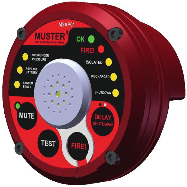
15 ISOLATED MODE This mode is selected using the DIP switch located inside the lid of the panel and is generally used to isolate the system during maintenance. Since the panel has no control of the discharge function in LOP systems this function is not enabled on LOP installations to avoid possible confusion. When a MusterWire LHD installation is isolated the panel will not discharge the system on detection of a fire, nor will it activate the Alarm, Fault or Shutdown relays. It will however continuously monitor all circuits for faults or fire and the appropriate indicator will light (non latching) enabling a technician to do fault-finding. When exiting this mode the panel will treat any fire detected within the first 4 seconds as a fault to avoid unintentional discharge. TEST FUNCTION: Press and hold this button for 5 seconds to enter a latched relay test mode, the button can be released at this point. In this mode the three relays will be energised in the following sequence with each successive press of the test button: FAULT relay - ALARM (fire) relay SHUTDOWN relay FAULT relay and so on. When a relay is activated the appropriate LED (FAULT, FIRE or SHUTDOWN) will blink continuously. To exit this relay test mode press and hold the TEST button for 2 seconds. The relay test mode will automatically exit if the TEST button is not pressed for 60 seconds. This mode is useful to test the integrity of the wiring of an installation. STANDBY MODE (OK MODE) The OK LED indicates that all systems are functioning correctly and monitoring for fire conditions. TEST FUNCTION: Briefly pressing the TEST button will activate (test) the buzzer and all LEDs. Low Cylinder Pressure (ORANGE) System OK (GREEN) Fire Alert (RED) Low Battery (ORANGE) System Fault (ORANGE) Isolated Indicator (ORANGE) Discharge in Process (ORANGE) Shutdown Initiated (ORANGE) Mute Buzzer (GREEN) Test Buzzer Remote Fire (LHD Only) Dual function: LHD or LOP Page 15
16 FAULT MODE The Alarm Panel is able to detect a number of faults conditions. Most fault conditions are latched and can only be cleared by pressing the TEST button. This ensures that intermittent faults do not go unnoticed. Once a fault is latched the appropriate indicator will blink and the audible alarm will give a short pip every 3 seconds and the OK indicator will be off. Should the fault clear by itself (for example an intermittent open circuit) the OK led will indicate that the panel is now functioning correctly but the appropriate red indicator will remain lit until cleared by pressing the TEST button. REPLACE BATTERY Indicates the battery is due for replacement. Note that if the OK indicator remains lit the battery still has enough charge for the Alarm Panel to function correctly but should be replaced at the first opportunity. If the OK indicator is off then the battery is critical and the panel can no longer function correctly, the battery must be replaced immediately. OVER/UNDER PRESSURE Indicates that the pressure in the system is either below 9 bar or above 16 bar. SYSTEM FAULT Indicates there is an electrical fault. On the pressure transducer circuit the Alarm Panel will detect a short or open circuit as well as incorrectly wired or faulty pressure transducers. In MusterWire LHD installations the panel will also detect if there is a fault with the release solenoid. On the detection circuit the panel will detect an open circuit and a missing or faulty Resistor Plug (M2RP01). TEST FUNCTION: Briefly pressing the TEST button will activate (test) the buzzer and all LEDs. All latched faults will be cleared and all circuits will be tested any faults still detected will be latched and indicated. Use this button to clear any faults after they have been corrected. FIRE MODE The Alarm Panel will behave differently depending on the type of installation: MUTE FUNCTION: In FIRE MODE once the panel has completed the SHUTDOWN sequence will the MUTE function be enabled to allow the alarm to be silenced. Page 16
17 FIRE MODE: MUSTERWIRE LHD INSTALLATIONS In MusterWire LHD installations the Alarm Panel will detect a fire if any of the following conditions are met: Automatic activation of the MusterWire Linear Heat Detection as a result of excessive heat. Manual activation of a Remote Actuator (M2RA01) attached to the detector circuit. Manual activation of the FIRE button on the panel itself. Once activated the Alarm Panel goes through a strict sequence of events as follows: 1. The release solenoid is activated and remains activated for a period of 4 seconds. This triggers the release of the Cylinder Valve (M2VA01) which will continue to discharge without further action from the Alarm Panel. The DISCHARGED LED will flash during the four seconds that the solenoid is activated. 2. The ALARM relay contacts are activated. 3. The buzzer and FIRE indicator goes into a ½ second on ½ second off cycle. 4. If the SHUTDOWN delay is set to 0 seconds the SHUTDOWN relay will activate immediately, otherwise the SHUTDOWN delay timer starts to count down from its set value (see SETUP). 5. After the 4 second activation of the release solenoid the Alarm Panel will continue to monitor the pressure in the system and the DISCHARGED led will only be lit once the pressure drops below 3 bar. 6. Step 6 is skipped if the SHUTDOWN delay is set to 0 seconds: 5 seconds before actual SHUTDOWN the buzzer and FIRE indicator change to a ¼ second on ¼ second off cycle to indicate the impending shutdown. At any stage during the SHUTDOWN delay the operator can press the DELAY SHUTDOWN button to extend the delay by a further 6 seconds. This can be done a maximum of twice. After the SHUTDOWN delay is over the SHUTDOWN relay is energized and if this circuit is used the machine will shut down permanently. The buzzer and FIRE indicator will revert to a ½ second on ½ second off cycle seconds after shutdown the delay button can be held down and the machine can be started and relocated. Once the button is released the machine will shutdown instantly. Repairs to the fire suppression system should be completed first before the use of this function minutes after detection of a FIRE the Alarm Panel will go into a low power mode where the buzzer and FIRE led will only flash briefly every three seconds. EXITING FIRE MODE & RELEASING THE SHUTDOWN RELAY (MusterWire LHD systems) After a fire event the Alarm Panel remains in FIRE mode and the SHUTDOWN relay remains energized. The TEST button serves no purpose. To exit FIRE mode the following procedure must be followed: 1. Using a Hex Key, remove (for a minimum of 5 seconds) and then re-install the Alarm Panel face. This will release the SHUTDOWN relay. 2. Any manual call points that have been activated must be reset and any activated Linear Heat Detection wire (MusterWire) must be replaced to ensure there is no signal (closed circuit) on the detection circuit. 3. Press the TEST button to reset the Alarm Panel. If the Alarm Panel still detects a signal (closed circuit) on the detection circuit it will not reset see step 2 above. Page 17
18 FIRE MODE : LOP INSTALLATIONS In LOP installations the Alarm Panel monitors the pressure in the system and assumes a fire condition if the pressure drops rapidly. Once activated the Alarm Panel goes through a strict sequence of events as follows: 1. The ALARM relay contacts are activated. 2. The buzzer and FIRE indicator goes into a ½ second on ½ second off cycle. 3. The DISCHARGED indicator is lit. 4. If the SHUTDOWN delay is set to 0 seconds the SHUTDOWN relay will activate immediately, otherwise the SHUTDOWN delay timer starts to count down from its set value (see SETUP). 5. Step 5 is skipped if the SHUTDOWN delay is set to 0 seconds: 5 seconds before actual SHUTDOWN the buzzer and FIRE indicator change to a ¼ second on ¼ second off cycle to indicate the impending shutdown. At any stage during the SHUTDOWN delay the operator can press the DELAY SHUTDOWN button to extend the delay by a further 6 seconds. This can be done a maximum of twice. After the SHUTDOWN delay is over the SHUTDOWN relay is energized and if this circuit is used the machine will shut down permanently. The buzzer and FIRE indicator will revert to a ½ second on ½ second off cycle seconds after shutdown the delay button can be held down and the machine can be started and relocated. Once the button is released the machine will shutdown instantly. Repairs to the fire suppression system should be completed first before the use of this function minutes after detection of a FIRE the panel will go into a low power mode where the buzzer and FIRE led will only flash briefly every three seconds. EXITING FIRE MODE & RELEASING THE SHUTDOWN RELAY (LOP SYSTEMS): After a fire event the Alarm Panel remains in FIRE mode and the SHUTDOWN relay remains energized. The TEST button serves no purpose. To exit FIRE mode the following procedure must be followed: 1. Using a Hex Key, remove (for a minimum of 5 seconds) and then re-install the panel face. This will release the SHUTDOWN relay. 2. Press the TEST button to reset the Alarm Panel. Page 18
19 Notes Page 19

20 Cylinder Filling Manual, M2CM01 June 2013
Installation and user manual for the FX range of fire panels. 1, 2, 4 and 8 zone panels
 Installation and user manual for the FX range of fire panels 1, 2, 4 and 8 zone panels Contents Panel installation 3 Panel connections 3 Wiring connection drawings 4 Panel facilities 6 Installation check
Installation and user manual for the CF5000, MF5000 and FXP5000 range of fire panels
 CF5000, MF5000 and FXP5000 Installation and user manual for the CF5000, MF5000 and FXP5000 range of fire panels 16 zone panels Contents PANEL INSTALLATION...3 Installation...3 PANEL WIRING... 3 Mains power
SIMPLICITY CO CARBON MONOXIDE DETECTION & VENTILATION PANEL
 SIMPLICITY CO CARBON MONOXIDE DETECTION & VENTILATION PANEL USER MANUAL 1 Table of Contents 1 SAFETY INFORMATION...3 1.1 SAFETY PRECAUTIONS DURING NORMAL OPERATION OF PANEL...3 1.3 BATTERY INFORMATION...3
Saffire User & Installation Manual. IMPORTANT This manual should be left with the panel after installation.
 Saffire+ 8-12 User & Installation Manual IMPORTANT This manual should be left with the panel after installation. We reserve the right to change product specifications without prior notice. Copyright VRC
EG-400 Fire Detection Monitor
 EG-400 Fire Detection Monitor For Engine and Generator compartments Owner s manual with installation instructions Revision 2.3 (10/1/07) Our Business is Your Safety and Peace of Mind! Jim Shepherd Toll
MAG2/4. AL MAG2 Soft. Version 2.1 MAG4 Soft.Version 2.0 USER MANUAL
 FIRE CONTROL PANEL MAG2/4 USER MANUAL AL MAG2 Soft. Version 2.1 MAG4 Soft.Version 2.0 READ THIS MANUAL BEFORE CONNECTING THE EQUIPMENT AND KEEP IT SAFE FOR FUTURE REFERENCE. To call our technical support
Installation, Operating and Maintenance Manual
 STATUS ZONES CONTROLS FIRE FAULT DISABLED FIRE 1 2 3 4 5 6 7 8 TEST FAULT DISABLED 1 5 BUZZER SILENCE RESET 1 2 TEST 2 6 LAMP TEST 3 SUPPLY 3 7 SYSTEM FAULT 4 8 SOUNDERS ACTIVATE/ SILENCE 4 FAULTS INSTRUCTIONS
1200-HCM DIN RAIL MOUNTING FIRE SYSTEM MODULE Fire Detection & Extinguishant Control A R T PATOL LIMITED SUPPLY FAULT SOUNDER
 Application The unit is primarily intended for use where there is a requirement to integrate a limited fire protection function into a larger control equipment scheme, or in specialist applications where
PAT E N T System 88. COMPLIES WITH Singapore Standard : SS CP10 : 2005 British Standard : BS EN54-2 : 1998 BS EN54-4 : 1998 REV.00
 PAT E N T System 88 COMPLIES WITH Singapore Standard : SS CP10 : 2005 British Standard : BS EN54-2 : 1998 BS EN54-4 : 1998 REV.00 Pg 1 of 12 CONTENTS 1. GENERAL 1.1 Introduction 2 1.2 System Description
ANALOX 5001 Carbon Dioxide Monitor. User Manual ANALOX Analox 5001 Carbon Dioxide Monitor User Manual
 ANALOX 5001 ANALOX 5001 Carbon Dioxide Monitor User Manual Analox Sensor Technology Ltd 15 Ellerbeck Court, Stokesley Business Park North Yorkshire, TS9 5PT T: +44 (0)1642 711400 F: +44 (0)1642 713900
Beacon 200 Gas Monitor Operator s Manual. Part Number: RK Released: 6/6/08
 Beacon 200 Gas Monitor Operator s Manual Part Number: 71-2102RK Released: 6/6/08 Table of Contents Chapter 1: Introduction.................................................3 Overview.............................................................3
Models NFPA 1221-A, NFPA 1221-B Public Safety DAS Annunciator Panel. Revision E 61117
 Models NFPA 1221-A, NFPA 1221-B Public Safety DAS Annunciator Panel Revision E 61117 CAUTION: (Read This First) This panel has been designed to make it nearly bullet proof to mistakes made when wiring
GS100M Gas Detector. Technical Specification
 GS00M Detector Application Duomo is recognised within the Gas industry for providing a comprehensive range of low cost, high reliability gas detection for many applications. We have installed and commissioned
Fire Control Panel. Installation & Programming Manual TABLE OF CONTENTS
 Fire Control Panel Installation & Programming Manual TBLE OF CONTENTS Page Getting Started 2 Power Supply Unit 3 Inputs 4 Outputs 4 LED Indications 4 User Keypad Functions 5 Engineer Keypad Functions 6
Door Release Power Supply
 www.protectingpeople.co.uk Door Release Power Supply Engineer / Installation Manual Document: VI55.1 Protecting People Printed : 04/03/2004-1 - Ventcroft Ltd Door Release Power Supply Engineer / Installation
Flopurge TS. Operation Manual
 Flopurge TS Operation Manual Part Number 079-0204 Spectron Gas Control Systems United Kingdom Unit 4, Herald Court, University of Warwick Science Park, Coventry, CV4 7EZ +44 (0)24 7641 6234 sales@spectron-gcs.com
Flostop TS D7E and A8E. Operation Manual
 Flostop TS D7E and A8E Operation Manual United Kingdom Spectron Gas Control Systems Ltd, Unit 4, ATU1, University of Warwick science Park, Coventry, +44 (0) 24 7641 6234 sales@spectron-gcs.com Germany
INTELLIGENT FIRE TECHNOLOGY. Twinflex and Multipoint V3. User Guide (TO BE RETAINED BY USER) Issue 3
 Issue 3") INTELLIGENT FIRE TECHNOLOGY Twinflex and Multipoint V3 User Guide (TO BE RETAINED BY USER) 26-0340 Issue 3 Rafiki Protection Limited Rafiki policy is one of continual improvement and the right to change
INTELLIGENT FIRE TECHNOLOGY Twinflex and Multipoint V3 User Guide (TO BE RETAINED BY USER) 26-0340 Issue 3 Rafiki Protection Limited Rafiki policy is one of continual improvement and the right to change
QA16 Addressable System
 QA16 Addressable System Operating Manual HORING LIH INDUSTRIAL CO., LTD. www.horinglih.com QA16 System Characteristics Each loop can connect with 250 devices. Easy system programming through PC to panel.
Application, Installation, Operation & Maintenance Manual
 APPROVED BY:JBJ PRESCIENT III FIRE ALARM & GAS EXTINGUISHING CONTROL PANEL Application, Installation, Operation & Maintenance Manual PAGE 1 of 43 CONTENTS 1. INTRODUCTION... 3 2. GENERAL DESCRIPTION...
ZX1e ZX2e ZX5e. Document No Issue 01 user manual
 ZX1e ZX2e ZX5e Document No. 996-130 Issue 01 user manual MORLEY-IAS ZX2E/ZX5E Fire Alarm Control Panels Table of Contents 1 INTRODUCTION... 4 1.1 NOTICE... 4 1.2 WARNINGS AND CAUTIONS... 4 1.3 NATIONAL
FTEN1, FTEN2, & FTEN4 1, 2 & 4 ZONE FIRE DETECTION AND ALARM CONTROL PANELS
 QUICK USER GUIDE FOR, 2 & 4 ZONE PANELS INDICATORS COLOUR INDICATION MON FAULT Yellow On when a fault condition has occurred, or if no other fault Led is on, this indicates 24v auxiliary fuse failure.
OPERATION AND INSTALLATION MANUAL
 EX+Plus 2 ZONE, 1AREA EXTINGUISHANT CONTROL PANEL OPERATION AND INSTALLATION MANUAL INTRODUCTION The Premier EX Plus is a 2 zone, single area panel for controlling the release of extinguishing gases in
HRX Technical Manual. Version 1.2
 HRX 5000 Technical Manual Version 1.2 Contents: Specification...2 Connectors...5 RS-485 Network Connectors (J6 and J7)...5 RS-232 to Printer (J19)...6 RS-232 to PC (J8)...7 TCP/IP...8 Power (J21)...9 Fire
PNC 1000 SERIES 2, 4, 8 Zone Fire Alarm Control Panel
 PNC 1000 SERIES 2, 4, 8 Zone Fire Alarm Control Panel INSTALLATION, OPERATION AND MAINTENANCE MANUAL Version: CN-PM-1000.VER1.1-12/2012 EN54 INFORMATION In accordance with EN 54-2 clause 13.7, the maximum
EXTINGUISHING AGENT RELEASE MODULE
 EXTINGUISHING AGENT RELEASE MODULE Operation, Installation & Programming Manual Revision 3.00 Distributors For: 18-20 Brookhollow Ave telephone 02 8850 2888 www.firesense.com.au Baulkham Hills NSW 2153
GS100M Gas Detection Controller
 GS100M Gas Detection Controller GS100M 1 Zone Gas Detection Controller 1 Zone / Sensor Conventional Positive Safety IP44 EN61010-1 EN50270 FEATURES Single Zone Protection Positive Safety Option Detection
LEAKMONITOR MULTIZONE WATER LEAK DETECTION ALARM PANEL INSTALLATION AND USER OPERATION MANUAL
 LEAKMONITOR MULTIZONE WATER LEAK DETECTION ALARM PANEL INSTALLATION AND USER OPERATION MANUAL The LeakMonitor alarm panel is a microprocessor controlled fully adjustable alarm system suitable for multizone
Centaur TM II Cube Slave Alarm Signalling Equipment INSTALLATION GUIDE
 Centaur TM II Cube Slave Alarm Signalling Equipment INSTALLATION GUIDE General Description This guide provides a summary for installing and configuring the Centaur TM Cube Slave Alarm Signalling Equipment
HA-263K HA-263D. OWNER'S MANUAL Installation And Operation 8-ZONE ALARM CONTROL PANEL FOR HOME AND OFFICE PROTECTIONS OPEN THE CABINET FOR SERVICE
 D (OPERATION) INITIATE A DYNAMIC BATTERY TEST The system tests the back-up battery once every 24 hours. The owner can initiate a dynamic battery test at any time with the following codes while the system
Excel-EN Conventional Fire Control Panel
 Available as 2, 4, 6, 8,10 or 12 zones Approved to EN54-2 & 4 Modular expansion zone cards Programmable relays and outputs Optional additional sounder circuits Optional additional programmable outputs
BX444-Mc Gas Detector
 Installation and User Guide Rev.01. BX444-Mc Gas Detector Application Duomo is recognised within the gas industry for providing a comprehensive range of low cost, high reliability gas detection for many
Matrix2000. User Guide - CPD Advanced Analog Fire Alarm Control Panel 4 24 Zones. Version: 2.0 Revision: 1
 Matrix2000 User Guide - CPD Advanced Analog Fire Alarm Control Panel 4 24 s Version: 2.0 Revision: 1 IMPORTANT INFORMATION Limitation of liability It is mandatory, Matrix2000 panel to be installed in accordance
FEC400 Series. Installation Manual
 FEC400 Series Conventional microprocessor controlled fire detection and alarm panels with extinguishing control Installation Manual Version 2.3 / August 2004 Aritech is a GE Interlogix brand. http://www.geindustrial.com/ge-interlogix/emea
NZ 400 AUTOMATIC FIRE ALARM SYSTEM OPERATORS MANUAL
 NZ 400 AUTOMATIC FIRE ALARM SYSTEM OPERATORS MANUAL Document No...G108WO1.DOC Serial No... Issue Date...17 th SEPTEMBER 1999 Software Version...1.4 APPROVED TO: NZS 4512:1997 AS/NZS 3548:1992 Fire Alarm
Noby-448 User Operating Manual & Log Book Page 1 of 12. Fire Control Panel. User Operating Manual & Log Book
 Noby-448 User Operating Manual & Log Book Page 1 of 12 Fire Control Panel User Operating Manual & Log Book TABLE OF CONTENTS Page Introduction 1 Keypad Operation 2 LED Indications 3 What to do in the event
Installation and user manual for the BiWire / Conventional Repeater Panel
 Panel EFBWCV-REPEATER Contents Introduction.... 3 Purpose... 3 The Panel.... 3 Indication Equipment (IE).... 3 Power Supply Equipment (PSE).... 4 System Wiring.... 5 Status Indications.... 5 Repeater I/O....
F PC and AO OUTPUT BOARDS INSTRUCTION MANUAL. Blue-White. Industries, Ltd.
 F-2000 PC and AO OUTPUT BOARDS INSTRUCTION MANUAL Blue-White R Industries, Ltd. 500 Business Drive Huntington Beach, CA 92649 USA Phone: 714-89-8529 FAX: 714-894-9492 E mail: sales@blue-white.com or techsupport@blue-white.com
Fire Control Panel. Installation & Programming Manual TABLE OF CONTENTS
 Fire Control Panel Installation & Programming Manual TABLE OF CONTENTS Page Getting Started 2 Power Supply Unit 3 Remote Keypad Bus 3 Inputs & Outputs 4 User Keypad Functions 5 Engineer Keypad Functions
Watchguard WGAP864 User Manual
 Watchguard WGAP864 User Manual v1.0 Issued September 2016 1 2 Table of Contents Glossary... 5 1. Introduction to your Watchguard WGAP864... 6 2. Before Operating your Alarm System... 6 3. Understanding
INSTALLATION AND INSTRUCTION MANUAL
 INSTALLATION AND INSTRUCTION MANUAL SS650-013 013 SIREN LCS652-013 SIREN and Light Controller PLITSTR247 REV. F 12/9/13 NOTICE Due to continuous product improvements, we must reserve the right to change
CA5000 Liquid CO 2 Freezer Backup System
 CA5000 Liquid CO 2 Freezer Backup System OPERATING INSTRUCTIONS MANUAL HAMPSHIRE CONTROLS CORPORATION ONE GROVE STREET / P.O. BOX 516, DOVER, NEW HAMPSHIRE USA 03821 TEL. (603) 749-9424 FAX (603) 749-9433
SYSTEM MANUAL FT1-SB. Single Zone Fire Alarm System
 SYSTEM MANUAL FT1-SB Single Zone Fire Alarm System DOCUMENT HISTORY Issue Date Description Written By Checked By Draft 0 2/9/2008 Original Document. A. Shenouda C. Orr Issue 1 4/11/2011 Update drawing
LC1 & 2. Fire Alarm Panel 6\VWHPLQVWDOODWLRQRSHUDWLQJ PDLQWHQDQFH LQVWUXFWLRQV
 LC1 & 2 Fire Alarm Panel 6\VWHPLQVWDOODWLRQRSHUDWLQJ PDLQWHQDQFH LQVWUXFWLRQV ZIRCONLC1 One Zone Conventional Fire Panel ZIRCONLC2 Two Zone Conventional Fire Panel Compliant with EN54-2:1998 & EN54-4:1998
Specification/ Data Sheet
 Specification/ Data Sheet TRITON RP Agent Release Control Panel FEATURES Agent Release Control Panel designed specifically for suppression release operation with: Four initiating device circuits (IDCs)
IDS X-Series Installer Manual H Issued July 2013
 1 2 Contents 1. Keypads... 5 2. Introduction to the IDS X-Series... 9 Features of the IDS X-Series... 9 3. Installation and Wiring... 10 Installation Requirements... 11 End-of-Line Resistors... 11 Box
La Marche Manufacturing Company Option 16 Series. Digital Combined Accessory Package. Installation and Operation Manual
 La Marche Manufacturing Company www.lamarchemfg.com Option 16 Series Digital Combined Accessory Package Installation and Operation Manual This manual is subject to change without notice. You may obtain
GAS SUPRESSION CONTROL PANEL:
 GAS SUPRESSION CONTROL PANEL: MODEL NAME: COMPANY: DELTA 437/2, Main Road, Mandwali Fazalpur, Delhi-110092 Page 1 ABOUT THE PRODUCT ASES is very proud of to introduce DELTA the completely digital microprocessor
Intelligent Security & Fire Ltd
 full installation, commissioning and operating manuals can be downloaded from www.haes-systems.co.uk combined addressable / conventional fire alarm control panel User Guide Approved Document No. MFBU-04
TOTAL SOLUTIONS. Liquid Level Control Product Guide. MATELEC AUSTRALIA innovative by design
 TOTAL SOLUTIONS Liquid Level Control Product Guide MATELEC innovative by design Liquid Level Control Contents Dual Pump Controllers Section 1 The Range Common Features Operating Data Control Logic Setup
Syncro AS. Analogue Addressable Fire Control Panel. User Manual
 Syncro AS Analogue Addressable Fire Control Panel User Manual Man-1100 Issue 02 Nov. 2008 Index Section Page 1. Introduction...3 2. Safety...3 3. Panel Controls...4 3.1 Access Level 1...4 3.2 Access Level
Operating & Maintenance Manual. Alert-4 Ethernet LCD Master Alarm
 Operating & Maintenance Manual Alert-4 Ethernet LCD Master Alarm w w w. a m i c o. c o m Contents User Responsibility 4 Introduction 4 Features 5 Description of the Alarm 5 Shipment Details 5 The Alarm
Conventional Fire Control Panel (FKEP2, FKEP4, FKEP8) Operation and Maintenance Manual. Man-1078EL Issue 01 February 2014
 Operation and Maintenance Manual. Man-1078EL Issue 01 February 2014") Conventional Fire Control Panel (FKEP2, FKEP4, FKEP8) Operation and Maintenance Manual Man-1078EL Issue 01 February 2014 B Index Page 1. Introduction... 3 1B2. Safety and mounting... 3 2B3. Technical specification...
Conventional Fire Control Panel (FKEP2, FKEP4, FKEP8) Operation and Maintenance Manual Man-1078EL Issue 01 February 2014 B Index Page 1. Introduction... 3 1B2. Safety and mounting... 3 2B3. Technical specification...
Conventional Fire Alarm System 2014 V1.2
 Conventional Fire Alarm System 2014 V1.2 Product Overview Control Panel 2 Conventional Fire Panel GST102A 2 zone Fire panel GST104A 4 zone Fire panel GST108A 8 zone Fire panel GST116A 16 zone Fire Panel
Gas Safety Products. Installation, operating and maintenance 11/18/2015. Merlin 1000S+ Gas Utility & Electrical Isolation Controller
 Gas Safety Products Installation, operating and maintenance 11/18/2015 American Gas Safety LLC 1 Table of contents 1 General information... 3 2 Installation... 3 2.1 Panel Mounting.... 3 2.2 Power Supply....
FPX103C Auto DUAL LOOP AUTO/MANUAL FIRE CONTROL PANEL Iss 1.0
 FPX103C Auto DUAL LOOP AUTO/MANUAL FIRE CONTROL PANEL Iss 1.0 SUMMARY: Dual detection loops with full fault monitoring. Automatic extinguisher operation after shutdown. Double knock automatic activation
5000 INSTALLATION GUIDE
 5000 INSTALLATION GUIDE Table of Contents Section Page No 1. INTRODUCTION... 3 2. WARNINGS AND CAUTIONS... 3 3. UNPACKING... 3 4. INSTALLATION... 4 5. CONTROL PANEL - REMOVING ITEMS BEFORE MOUNTING...
Operation and Maintenance Manual
 (FKER Series) Repeater Panel (FKER, FKER, FKER8) Operation and Maintenance Manual Man-9EL Issue June Index Section Page. Introduction.... Safety and mounting.... Technical specification.... Control panel
Analox 1000 Series. User Manual. Analox Sensor Technology Ltd. 15 Ellerbeck Court, Stokesley Business Park North Yorkshire, TS9 5PT, UK
 Analox 1000 Series User Manual Analox Sensor Technology Ltd. 15 Ellerbeck Court, Stokesley Business Park North Yorkshire, TS9 5PT, UK T: +44 (0)1642 711400 F: +44 (0)1642 713900 W: www.analox.net E: info@analox.net
Smoke Vent Control Panel PCB4 V4 Installation Manual
 Smoke Vent Control Panel PCB4 V4 Installation Manual 10A PCB4 Control Panel Do Not Remove From PCB4 Control Panel www.besafedirect.com Page 1 Contents Page 3) Important Regulations, Safety, Maintenance,
Beacon 800 Gas Monitor Operator s Manual
 Beacon 800 Gas Monitor Operator s Manual Part Number: 71-0037RK Revision: F Released: 4/18/17 www.rkiinstruments.com Product Warranty RKI Instruments, Inc. warrants gas alarm equipment sold by us to be
Manual# User s Manual. DCU 410/408 Engine Control Unit RP 410 Remote Panel FW 2.3
 Manual# 1100268 User s Manual DCU 410/408 Engine Control Unit RP 410 Remote Panel FW 2.3 Table of Content GENERAL INFORMATION... 3 ABOUT THIS MANUAL... 3 400 SERIES OVERVIEW... 3 Available Modules...
THANK YOU FOR VOTING TEXECOM INSTALLATION MANUAL. Security Control Panel with Communicator Interface
 THANK YOU FOR VOTING TEXECOM INSTALLATION MANUAL Security Control Panel with Communicator Interface Table of Contents Table of Contents Section Page 1 Programming Summary 4 1.1 Programming Menu 4 1.1.1
Sigma. K1000 Series 1, 2, 4 & 6 Zone Fire Control Panels. Operation and Maintenance Manual. Man-1048 Issue 05 October 2009
 Sigma K1000 Series 1, 2, 4 & 6 Zone Fire Control Panels Operation and Maintenance Manual Man-1048 Issue 05 October 2009 CONTENTS Contents... Page Safety & Installation...2 Installation - continued...3
Pioneer-R16 Gas Monitor Operator s Manual
 Pioneer-R16 Gas Monitor Operator s Manual Edition 7/2/97 RKI INSTRUMENTS, INC RKI Instruments, Inc. 33248 Central Ave, Union City, CA 94587 (510) 441-5656 Chapter 1: Description About the Pioneer-R16 Gas
Electric Release Panel Wiring Tips
 R IPS CARBO STEEL PIPE FIRE PROTECTIO PRODUCTS Electric Release Panel Wiring Tips 30.4 VICTAULIC IS A ISO 900 CERTIFIED COMPAY Model PDRP-00 Releasing Panels are compact single enclosure units containing
MULTIGUARD MULTIGUARD USERS MANUAL TYPE S3/240W 26/01/2010
 195,00 mm N MAIN CONNECTION Description Type S3 240W Uninterruptable Power Supply is an industrial grade unit for stationary and indoor use only. ACCESS HOLE FOR OUTPUT VOLTAGE ADJUSTMENT PROTECTION UNIT
Intelligent Security & Fire Ltd
 OPERATIONAL NOTES FOR CONCEPT FIRE PANEL. NOTE ON NEW FIRE PANELS, POSITION 1 ON THE SIX WAY INTERNAL OPTION SWITCH IS TURNED ON, DISABLING THE ZONAL SOUNDERS. TO ENABLE ZONAL SOUNDERS TURN OFF. Operation
MO144. Operators Guide. Universal Timer Module
 EN Operators Guide Universal Timer Module Operators Guide Notices EN Copyright Notice Unless otherwise indicated, this publication is the copyright of Bosch Security Systems, Inc. ( Bosch ). All rights
FIREPRO INSTALLATION MANUAL FIRE ALARM CONTROL PANEL INSTALLATION MANUAL. Approved Document No. GLT Issue: 1. 8 Author: NRPJ Date: 7/ 3/201 4
 FIRE ALARM CONTROL PANEL INSTALLATION MANUAL Approved Document No. GLT -201-7-3 Issue: 1. 8 Author: NRPJ Date: 7/ 3/201 4 CONTENTS 1. INTRODUCTION... 1.1 HANDLING THE PCBS... 1.2 USING THIS MANUAL... 1.3
Intruder - Fire - Water Combined Alarm
 65 Intruder - Fire - Water Combined Alarm Installation Manual and User Operating Instructions TALE OF CONTENTS Page First Power-Up 2 Power Supply Unit 3 Input & Detection Circuits 3 Output & Alarm Circuits
BiWire Flexi. BiWire Flexi Fire Panel EFBW8ZONE-FLEXI / EFBW4ZONE-FLEXI / EFBW2ZONEFLEXI Installation Manual
 BiWire Flexi BiWire Flexi Fire Panel EFBW8ZONE-FLEXI / EFBW4ZONE-FLEXI / EFBW2ZONEFLEXI Installation Manual Contents Contents 1. INTRODUCTION... 4 1.1 Purpose...4 2. THE BIWIRE FLEXI FIRE DETECTION & ALARM
THX-DL Data Logger USER & INSTALLATION MANUAL V
 THX-DL Data Logger USER & INSTALLATION MANUAL V1.2012 www.thermomax-refrigeration.com Contents PRESENTATION Summary of Features 2 INSTALLATION Safety Precautions 4 THX Unit 4 Sensors 4 Alarm Relay 4 Power
ANALOX 3000 Carbon Monoxide Monitor
 ANALOX 3000 Carbon Monoxide Monitor User Manual Analox Sensor Technology Ltd 15 Ellerbeck Court, Stokesley Business Park North Yorkshire, TS9 5PT T: +44 (0)1642 711400 F: +44 (0)1642 713900 W: www.analox.net
Refrigeration Controller Operator s Manual (HRC) PO Box 6183 Kennewick, WA
 PO Box 6183 Kennewick, WA") Refrigeration Controller Operator s Manual (HRC) PO Box 6183 Kennewick, WA 99336 www.jmcvr.com 1-509-586-9893 Table of Contents TABLE OF FIGURES...1 OVERVIEW OF THE HRC CAPABILITIES...2 INSTALLATION AND
Refrigeration Controller Operator s Manual (HRC) PO Box 6183 Kennewick, WA 99336 www.jmcvr.com 1-509-586-9893 Table of Contents TABLE OF FIGURES...1 OVERVIEW OF THE HRC CAPABILITIES...2 INSTALLATION AND
ViewMatrix. Software for Online Monitoring & Control of Matrix2000 Conventional Fire Alarm Panels. Version: 2.0 Revision: 0.1
 ViewMatrix Software for Online Monitoring & Control of Matrix2000 Conventional Fire Alarm Panels Version: 2.0 Revision: 0.1 CONTENTS 1. Introduction...3 2. Keyboard...5 2.1 POWER indication - Normal Operation...5
Installation Manual Premier 412/816/832. Issue 10
 Installation Manual Premier // Issue 0 Premier // Installation Manual 5. Operating the System Introduction Before attempting to operate the alarm system ensure you have familiarised yourself with all the
GasScanner 8C. Eight Channel Monitor. Operator s Manual. MINT-0281-XX Rev. A 01/29/08
 GasScanner 8C Eight Channel Monitor Operator s Manual MINT-0281-XX Rev. A 01/29/08 Product Warranty Matheson Tri-Gas, Inc., warrants gas alarm equipment sold by us to be free from defects in materials,
Control Panel Engineering and Commissioning Instructions
 Twinflex - V3 Fire Detection & Alarm System Control Panel Engineering and Commissioning Instructions (TO BE RETAINED BY THE COMMISSIONING ENGINEER) 26-0338 Issue 9 Fike s policy is one of continual improvement
4 & 8-POINT ANNUNCIATORS Instruction Manual
 4 & 8-POINT ANNUNCIATORS Instruction Manual 8 Field Selectable Sequences All Common ISA Sequences 4 or 8-Point (Channel) Monitoring Free Replaceable Message Labels Type 4X, NEMA 4X, IP65 Front Universal
IMR IX176 Portable Gas Detector User Manual
 IMR Portable Gas Detector User Manual Read this manual carefully before using this device. (727) 328-2818 / (800) RING-IMR Fax: (727) 328-2826 www.imrusa.com Ver. 1.0A4 CONTENTS SERVICE GUIDELINES... 3
D-TEK O P E R A T I N G I N S T R U C T I O N S V E HI C L E L O O P DETECTOR Johnston Parkway, Cleveland, Ohio 44128
 O P E R A T I N G I N S T R U C T I O N S D-TEK V E HI C L E L O O P DETECTOR 4564 Johnston Parkway, Cleveland, Ohio 44128 P. 800 426 9912 F. 216 518 9884 Sales Inquiries: salessupport@emxinc.com Technical
Operating manual and Log book for the range of 1,2,4 and 8 zone fire Control and Repeat panels
 Operating manual and Log book for the range of 1,2,4 and 8 zone fire Control and Repeat panels The panels are designed in accordance with the requirements of EN54 Part 2:1997 (and include optional clauses
10yr O2NE & Safe-Ox. User Manual
 Analox Ltd. 15 Ellerbeck Court, Stokesley Business Park North Yorkshire, TS9 5PT, UK T: +44 (0)1642 711400 F: +44 (0)1642 713900 W: www.analox.net E: info@analox.net This support line is closed on UK public
CONTROL DEVICE SLIDETRONIC HD
 CONTROL DEVICE SLIDETRONIC HD to control gravity self-closing fire gates Producer: Somati system s.r.o. Jihlavská 510/2c 664 41 Troubsko, okr.brno - venkov Tel.: 547 427 011 Fax: 547 427 013 E-mail: export@somati-system.cz
CHECKFIRE 210 Detection and Actuation System
 DATA SHEET CHECKFIRE 210 Detection and Actuation System Features Supervised power, detection, release, and communication circuits Display module with LED system status indicators Adjustable mounting bracket
GL-CO-RFG Channel Gas Leak Alarm System
 Four Elms Road Edenbridge Kent TN8 6AB UK Features & Benefits Remote sensors for natural gas, LPG and CO 1 x SPST relay outputs DIN-rail as standard, panel mounting kit available Adjustable alarm thresholds
3500 CONVENTIONAL FIRE ALARM CONTROL PANEL
 3500 CONVENTIONAL FIRE ALARM CONTROL PANEL INSTALLATION AND COMMISSIONING MANUAL Protec Fire Detection PLC, Protec House, Churchill Way, Nelson, Lancashire, BB9 6RT. Telephone: +44 (0) 1282 717171 Fax:
Introduction... 1 System Overview... 1 System Diagram... 2
 TABLE OF CONTENTS Introduction... 1 System Overview... 1 System Diagram... 2 Installation... 3 Console Mounting... 3 Monitor And Power Connections... 3 ASM II Console Main Harness... 4 Module Mounting...
DUAL MONITORED INPUT/OUTPUT UNIT BN-305
 DUAL MONITORED INPUT/OUTPUT UNIT BN-30 Interactive fire detection systems Product Datasheet Features Interactive For interfacing and controlling external units to Autronica s interactive fire detection
OPERATING AND MAINTENANCE MANUAL. for the G30 CARBON DIOXIDE MONITOR
 OM117 OPERATING AND MAINTENANCE MANUAL for the G30 CARBON DIOXIDE MONITOR (Part No: G30) (Intentionally Blank) APPROVAL SHEET DIVEX MANUAL NUMBER: ADVITIUM NUMBER: DOCUMENT TITLE: OM117 GA-OM-5715 G30
ZSC100 Gas Detection and Alarm System Controller
 ZSC100 Gas Detection and Alarm System Controller User Guide 1- Introduction... 3 1.1- General description... 3 1.2- Cautions and warnings... 3 2- Control panel... 4 2.1 Control panel overview... 4 2.2
LEAKSTOPPER MULTIZONE WATER LEAK DETECTION ALARM PANEL INSTALLATION AND OPERATION MANUAL
 LEAKSTOPPER MULTIZONE WATER LEAK DETECTION ALARM PANEL INSTALLATION AND OPERATION MANUAL The LeakStopper Multizone detects the presence of water in environments where it is not supposed to be. Should water
Installation Instructions. PS902 Power Supply. These instructions cover the following parts: PS902 Power Supply Specifi cations:
 F1! 44487023 These instructions cover the following parts: PS902 Power Supply Installation Instructions! DANGER: To avoid risk of electric shock, turn off AC power before installing or servicing PS902
Public Safety DAS Annunciator Panel
 Public Safety DAS Annunciator Panel 120 VAC Models: 1221-A, 1221-B, 1221-C Revision D 91117 48 VDC Models: 1221-A-48, 1221-B-48, 1221-C-48 24 VDC Models: 1221A-24, 1221-B-24, 1221-C-24 CAUTION: (Read This
INSTRUCTION MANUAL T119 1MN0110 REV. 0. operates with ISO9001 certified quality system
 INSTRUCTION MANUAL 1MN0110 REV. 0 operates with ISO9001 certified quality system TECSYSTEM S.r.l. 20094 Corsico (MI) Tel.: +39-024581861 Fax: +39-0248600783 http://www.tecsystem.it R. 1.1 25/08/16 ENGLISH
E N G L I S H FIRE ALARM ASPIRATION SENSING TECHNOLOGY QUICK INSTALLATION GUIDE STAND-ALONE FAAST LT MODELS FL0111E FL0112E FL0122E. 367 mm.
 E N G L I S H FIRE ALARM ASPIRATION SENSING TECHNOLOGY QUICK INSTALLATION GUIDE STAND-ALONE FAAST LT MODELS FL0E FL0E FL0E mm mm 0 mm DESCRIPTION The LT FL0 Series is part of the Fire Alarm Aspiration
User manual and installation instruction Control for Fire Ventilation RV / RV 24-32
 User manual and installation instruction Control for Fire Ventilation RV 24-24 / RV 24-32 Fire ventilation Comfort ventilation 24VDC max. 24/32A 2 Actuator outputs 1 Fire ventilation group, 2 comfort groups
IDM4 CARAVAN ALARM. Operating instructions
 IDM4 CARAVAN ALARM Operating instructions Factory Settings Entry Delay - 0:00 (0 secs) Exit Delay - 0:20 (20secs) Siren On Time - 1:00 (1 minute) Manufacturers Personal Code - 1234 Operation Alarm Keypad
Introduction... 1 System Overview... 1 System Diagram... 2
 Introduction... 1 System Overview... 1 System Diagram... 2 Installation... 3 Mounting... 3 Monitor And Power Connections... 3 Harness Connection... 4 Monitor Connection... 5 System Configuration... 7 Powering