Model 685B1001A10. Electronic Vibration Switch. Installation and Operating Manual
|
|
|
- Tyrone Preston
- 5 years ago
- Views:
Transcription


1 Model 685B1001A10 Electronic Vibration Switch Installation and Operating Manual For assistance with the operation of this product, contact PCB Piezotronics, Inc. Toll-free: hour SensorLine: Fax: Web:
2 Service, Repair, and Return Policies and Instructions The information contained in this document supersedes all similar information that may be found elsewhere in this manual. Service Due to the sophisticated nature of the sensors and associated instrumentation provided by PCB Piezotronics, user servicing or repair is not recommended and, if attempted, may void the factory warranty. Routine maintenance, such as the cleaning of electrical connectors, housings, and mounting surfaces with solutions and techniques that will not harm the physical material of construction, is acceptable. Caution should be observed to ensure that liquids are not permitted to migrate into devices that are not hermetically sealed. Such devices should only be wiped with a dampened cloth and never submerged or have liquids poured upon them. Repair In the event that equipment becomes damaged or ceases to operate, arrangements should be made to return the equipment to PCB Piezotronics for repair. User servicing or repair is not recommended and, if attempted, may void the factory warranty. Calibration Routine calibration of sensors and associated instrumentation is recommended as this helps build confidence in measurement accuracy and acquired data. Equipment calibration cycles are typically established by the users own quality regimen. When in doubt about a calibration cycle, a good rule of thumb is to recalibrate on an annual basis. It is also good practice to recalibrate after exposure to any severe temperature extreme, shock, load, or other environmental influence, or prior to any critical test. PCB Piezotronics maintains an ISO certified metrology laboratory and offers calibration services, which are accredited by A2LA to ISO/IEC 17025, with full traceability to SI through N.I.S.T. In addition to the normally supplied calibration, special testing is also available, such as: sensitivity at elevated or cryogenic temperatures, phase response, extended high or low frequency response, extended range, leak testing, hydrostatic pressure testing, and others. For information on standard recalibration services or special testing, contact your local PCB Piezotronics distributor, sales representative, or factory customer service representative. Returning Equipment Following these procedures will ensure that your returned materials are handled in the most expedient manner. Before returning any equipment to PCB Piezotronics, contact your local distributor, sales representative, or factory customer service representative to obtain a Return Warranty, Service, Repair, and Return Policies and Instructions Materials Authorization (RMA) Number. This RMA number should be clearly marked on the outside of all package(s) and on the packing
3 list(s) accompanying the shipment. A detailed account of the nature of the problem(s) being experienced with the equipment should also be included inside the package(s) containing any returned materials. A Purchase Order, included with the returned materials, will expedite the turn-around of serviced equipment. It is recommended to include authorization on the Purchase Order for PCB to proceed with any repairs, as long as they do not exceed 50% of the replacement cost of the returned item(s). PCB will provide a price quotation or replacement recommendation for any item whose repair costs would exceed 50% of replacement cost, or any item that is not economically feasible to repair. For routine calibration services, the Purchase Order should include authorization to proceed and return at current pricing, which can be obtained from a factory customer service representative. complete list of distributors and offices can be found at Customers within the United States may contact their local sales representative or a factory customer service representative. A complete list of sales representatives can be found at Toll-free telephone numbers for a factory customer service representative, in the division responsible for this product, can be found on the title page at the front of this manual. Our ship to address and general contact numbers are: PCB Piezotronics, Inc Walden Ave. Depew, NY14043 USA Toll-free: (800) hour SensorLine SM : (716) Website: info@pcb.com Contact Information International customers should direct all inquiries to their local distributor or sales office. A

4 PCB 工业监视和测量设备 - 中国 RoHS2 公布表 PCB Industrial Monitoring and Measuring Equipment - China RoHS 2 Disclosure Table 有害物质 部件名称 铅 (Pb) 汞 (Hg) 镉 (Cd) 六价铬 (Cr(VI)) 多溴联苯 (PBB) 多溴二苯醚 (PBDE) 住房 O O O O O O PCB 板 X O O O O O 电气连接器 O O O O O O 压电晶体 X O O O O O 环氧 O O O O O O 铁氟龙 O O O O O O 电子 O O O O O O 厚膜基板 O O X O O O 电线 O O O O O O 电缆 X O O O O O 塑料 O O O O O O 焊接 X O O O O O 铜合金 / 黄铜 X O O O O O 本表格依据 SJ/T 的规定编制 O: 表示该有害物质在该部件所有均质材料中的含量均在 GB/T 规定的限量要求以下 X: 表示该有害物质至少在该部件的某一均质材料中的含量超出 GB/T 规定的限量要求 铅是欧洲 RoHS 指令 2011/65/ EU 附件三和附件四目前由于允许的豁免 CHINA RoHS COMPLIANCE
5 Component Name Lead (Pb) Mercury (Hg) Cadmium (Cd) Hazardous Substances Chromium VI Compounds (Cr(VI)) Polybrominated Biphenyls (PBB) Polybrominated Diphenyl Ethers (PBDE) Housing O O O O O O PCB Board X O O O O O Electrical O O O O O O Connectors Piezoelectric X O O O O O Crystals Epoxy O O O O O O Teflon O O O O O O Electronics O O O O O O Thick Film O O X O O O Substrate Wires O O O O O O Cables X O O O O O Plastic O O O O O O Solder X O O O O O Copper Alloy/Brass X O O O O O This table is prepared in accordance with the provisions of SJ/T O: Indicates that said hazardous substance contained in all of the homogeneous materials for this part is below the limit requirement of GB/T X: Indicates that said hazardous substance contained in at least one of the homogeneous materials for this part is above the limit requirement of GB/T Lead is present due to allowed exemption in Annex III or Annex IV of the European RoHS Directive 2011/65/EU. DOCUMENT NUMBER: DOCUMENT REVISION: D ECN: 46162
 684-0003 Fax (716) 684-3823 Toll Free Line 1-800-959-4IMI MANUAL NUMBER: 34181 MANUAL REVISION: H ECO#")
6 685B-Series Electronic Vibration Switch Operating Guide with Enclosed Warranty Information 3425 Walden Avenue, Depew, New York Phone (716) Fax (716) Toll Free Line IMI MANUAL NUMBER: MANUAL REVISION: H ECO# 47640
7 Table of Contents Introduction... Page 3 General Features Specifications... Page 4 Installation and Wiring... Page 5 Installation & Dimensional Drawings Pin Location Diagram- Models with Internal Accelerometer and Triac Relays Pin Location Diagram- Models with Internal Accelerometer and Electromechanical Relays Pin Location Diagram- Models with External Accelerometer and Triac Relays Pin Location Diagram- Models with External Accelerometer and Electromechanical Relays Configuring the 685B... Page 11 Internal Diagram- Models with Triac Relays Internal Diagram- Models with Electromechanical Relays Using Calibration Mode Connecting the Remote Reset Connecting the Raw Vibration Output Optional Accessories... Page A209 Adapter Plate 699A05 Portable 4-20 ma Calibrator ESD Sensitivity... Page 16 Ordering Information/ Model Matrix... Page 17 PAGE 2
8 Introduction The 685B-Series is an electronic vibration switch designed to monitor vibration levels and trip an alert when a specified limit is exceeded. A second onboard relay trips an alarm that can be used to shut down a piece of equipment or act as a secondary alert level. An onboard accelerometer with precision electronics insures reliability and accuracy. General Features Embedded or external piezoelectric accelerometer for improved accuracy and frequency response. Vibration range can be measured in acceleration, velocity or displacement (factory set). Provides dual 5 Amp Triac (SPST) or 10 Amp Form C (SPDT) relay outputs. Adjustable trip limits and time delay via single turn potentiometers. Accommodates normally open (NO) and normally closed (NC) wiring schemes. Continuous or latching switch action. Local reset button and remote reset capability. LED indicators for power, alert and alarm. Screw terminal blocks for easy wiring. Mounts directly to the equipment being monitored via four bolt pattern. Flexible design allows for various custom requirements ma field calibration feature for improved accuracy. Raw vibration & 4-20 ma outputs as standard. PAGE 3
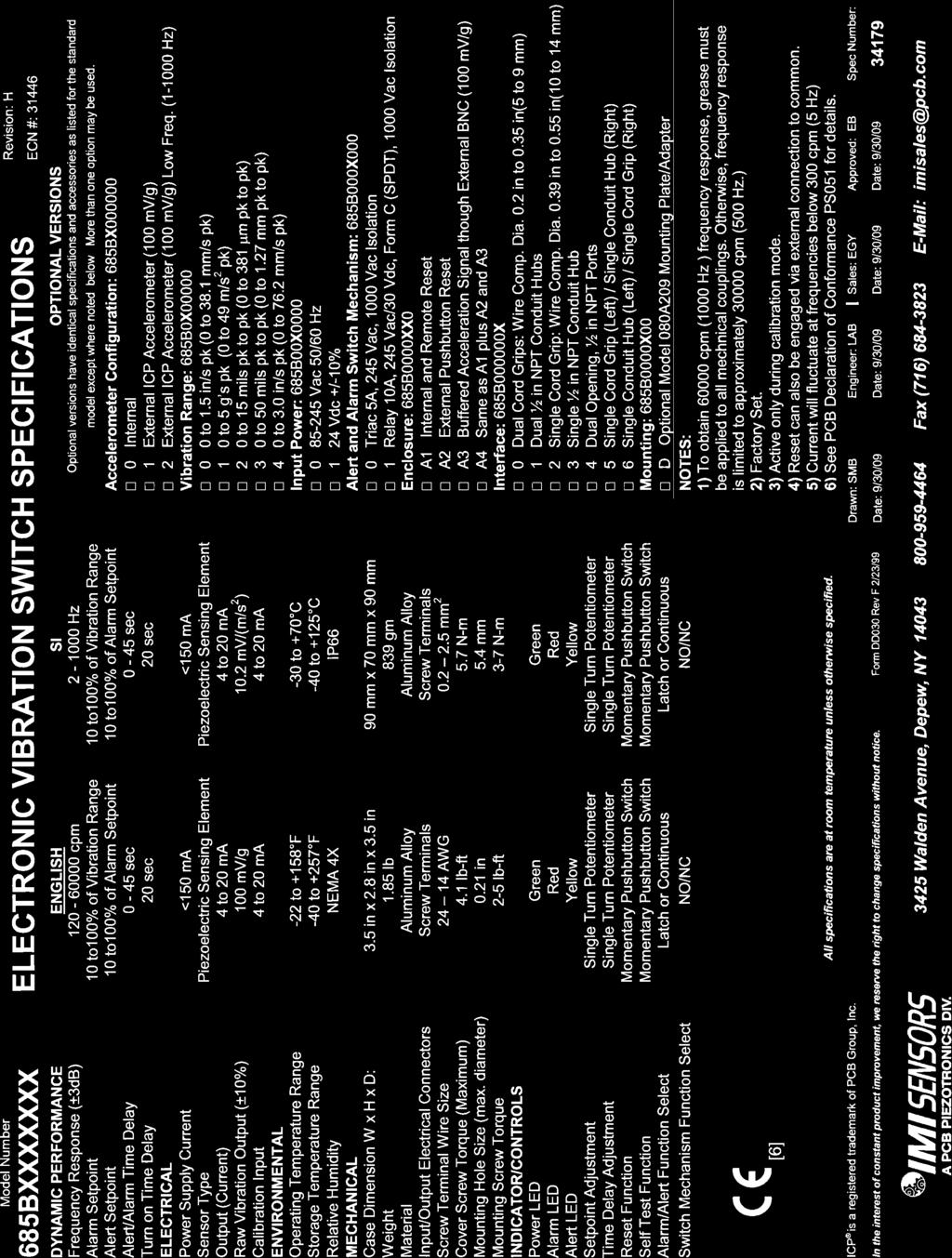
9 Specifications Power Supply Voltage: VAC, VDC (factory set) Power Supply Current: 150 ma max Sensor Type: Piezoelectric Sensing Element Standard Vibration Ranges: 0-5g pk, ips pk, 0-3 ips pk, 0-50 mils pk-pk, 0-15 mils pk-pk (factory set) Frequency Response +/-3dB: 2Hz to 1Khz (120 60,000cpm) Turn on Time Delay: 20 seconds Alert/Alarm Time Delay: 0-45 seconds Alert/Alarm Function Select: Latch or Continuous Alert/Alarm Switches: 5A/245Vac Triac (SPST) or 10A/245Vac 5A/30Vdc Form C Relay (SPDT) Operating Temperature Range: -22 to 158 F (-30 to 70 C) Storage Temperature Range: -40 to 257 F (-40 to 125 C) Relative Humidity:... NEMA 4X Rating Case Dimension W x H x D: 3.5 x 2.8 x 3.5in. (90 x 70 x 90mm) Weight: 1.85 lbs. (839 grams) Case Material: Aluminum Alloy Input/Output Electrical Connectors: Screw Terminals Screw Terminal Wire Size: AWG ( mm 2 ) Wiring Interface: Cord Grips (wire comp. dia ) or ½ NPT Conduit Hubs Mounting Hole Size: 0.21 inches Mounting Screw Torque: 2-5 ft. lbs. (3-7Nm) LED Indicators: Power: Alarm: Alert: - Green - Red - Yellow Alert/ Alarm Setpoint: Single Turn Potentiometer (10-100% Full Scale Range) Reset Function: Momentary Pushbutton Switch and/or Remote to Common. PAGE 4
10 Installation and Wiring Installation The 685B-Series is designed to be mounted directly on the equipment to be monitored using a four-bolt pattern. There are also options to retrofit existing 3 bolt pattern installations. (Model 080A209 mounting plate requiredsee optional accessories on page 13). Use grease between all surfaces to insure specified frequency response, otherwise performance will be degraded. The axis of vibration measured by models with internal accelerometers is perpendicular to the mounting orientation of the unit. Standard Model Dimension Drawing with Cord Grips Inch (mm) PAGE 5
11 Standard Model Dimension Drawing with ½ NPT Conduit Hubs Inch (mm) PAGE 6
12 Explosion Proof Model Dimension Drawing Inch (mm) WARNING AC and DC input signals and power supply voltages could be hazardous. DO NOT connect live wires to screw terminal plugs, and DO NOT insert, remove, or handle screw terminal plugs with live wires connected. PAGE 7
13 Connector and Pinout Diagram The 685B-Series uses screw terminal connectors for all input and output connections. Strip off 0.3 (8mm) of insulation from the connection wire ends. Feed the wire through the access ports, and terminate the wire in the correct location. Once connected, tug lightly on the wire to confirm connection is secure. Pin Location Diagram- Models with Internal Accelerometer and Triac Relays Pin Category Description 1 + Power 2 AC Power - Power/Common 3 Earth Ground (Also connect to enclosure safety lug) 4 Main Terminal 1 Alarm Output 5 Main Terminal 2 6 Main Terminal 1 Alert Output 7 Main Terminal 2 8 N/A N/A 9 N/A 10 Common Raw Vibration Output 11 +Signal 12 Remote Reset Connection (Do not apply power) 13 Control Configurations Common Connection 14 Calibration Connection ma Current Output ma PAGE 8
14 Pin Location Diagram- Models with Internal Accelerometer and Electromechanical Relays Pin Category Description 1 + Power 2 AC Power - Power/Common 3 Earth Ground (Also connect to enclosure safety lug) 4 Normally Closed (when dipswitch is in de-energized position) 5 Alarm Output Common connection 6 Normally Open (when dipswitch is in de-energized position) 7 Normally Closed (when dipswitch is in de-energized position) 8 Alert Output Common connection 9 Normally Open (when dipswitch is in de-energized position) 10 Common Raw Vibration Output 11 +Signal 12 Remote Reset Connection (Do not apply power) 13 Control Configurations Common Connection 14 Calibration Connection ma Current Output ma PAGE 9
15 Pin Location Diagram- Models with External Accelerometer and Triac Relays When the external 100mV/g ICP sensor option is specified, an additional terminal block location is added to the 685B-Series. The external accelerometer is connected to +Sensor and Sensor positions as indicated in the above figure and on the product label locate inside the top cover. The cable shield to the accelerometer should be grounded as required by local codes as well as to limit RFI/EMI interference. Pin Category Description 1 + Power 2 AC Power - Power/Common 3 Earth Ground (Also connect to enclosure safety lug) 4 Main Terminal 1 Alarm Output 5 Main Terminal 2 6 Main Terminal 1 Alert Output 7 Main Terminal 2 8 N/A N/A 9 N/A 10 + Sensor Sensor Input & 11 - Sensor/Common Raw Vibration Output 12 +Signal 13 Remote Reset Connection (Do not apply power) 14 Control Configurations Common Connection 15 Calibration Connection ma Current Output ma PAGE 10
16 Pin Location Diagram- Models with External Accelerometer and Electromechanical Relays When the external 100mV/g ICP Sensor option is specified, an additional terminal block location is added to the 685B-Series. The external accelerometer is connected to +Sensor and Sensor positions as indicated in the above figure and on the product label locate inside the top cover. The cable shield to the accelerometer should be grounded as required by local codes as well as to limit RFI/EMI interference. Pin Category Description 1 + Power 2 AC Power - Power/Common 3 Earth Ground (Also connect to enclosure safety lug) 4 Normally Closed (when dipswitch is in de-energized position) 5 Alarm Output Common connection 6 Normally Open (when dipswitch is in de-energized position) 7 Normally Closed (when dipswitch is in de-energized position) 8 Alert Output Common connection 9 Normally Open (when dipswitch is in de-energized position) 10 + Sensor Sensor Input & 11 - Sensor/Common Raw Vibration Output 12 +Signal 13 Remote Reset Connection (Do not apply power) 14 Control Configurations Common Connection 15 Calibration Connection ma Current Output ma PAGE 11
17 Configuring the 685B-Series Internal Diagram- Models with Triac Relays The internal diagram displays the location of the control features for the triac versions of the 685B-Series. The alert and alarm set points are adjusted via the single turn potentiometers. The alarm relay is set using the first potentiometer, and the alert relay is set using the third. The alert relay trips when the set percentage of the alarm value is reached. Time delays for both functions are controlled using the second and fourth potentiometers. Alert and alarm relays can be reset remotely by using the RESET and COMM pins or by using the internal reset switch as seen on the upper right hand corner of the diagram. Using the dipswitches beneath the terminal connectors, relay operation can be selected to be either latch or continuous, and each relay can be separately configured to be normally open (de-energized) or normally closed (energized). There is also a dipswitch to activate the calibration mode for condition simulation during the setup process. This is explained in detail on page 13. PAGE 12
18 Internal Diagram- Models with Electromechanical Relays The internal diagram displays the location of the control features for the relay versions of the 685B-Series. The alert and alarm set points are adjusted via the single turn potentiometers. The alarm relay is set using the first potentiometer, and the alert relay is set using the third. The alert relay trips when the set percentage of the alarm value is reached. Time delays for both functions are controlled using the second and fourth potentiometers. Alert and alarm relays can be reset remotely by using the RESET and COMM pins or by using the internal reset switch as seen on the upper right hand corner of the diagram. Using the first dipswitch beneath the terminal connectors, relay operation can be selected to be either latch or continuous. The second and third dipswitches set the alert and alarm relay configuration to be energized or deenergized. The diagram above indicates the contacts that are normally open and normally closed when the dip switch is set to de-energized. When the dipswitch is changed to energized, the normally open and normally closed contacts would be reversed. The fourth dipswitch is used to activate the calibration mode for condition simulation during the setup process. This is explained in detail on page 12. PAGE 13
19 Using Calibration Mode The 685B-Series has the unique ability to be calibrated using a 4-20 ma simulator. (IMI Sensors model 699A05, see Accessories page) This allows for a much more accurate and quantifiable calibration versus manually attuning the switch. The following steps allow for simple calibration using this configuration. 1) Connect the 4-20 ma simulator signal across the COMM and CAL pins. 2) Turn the calibration dipswitch to on. This will disable the switch s ability to measure physical vibration. 3) Turn both time delay potentiometers to zero for calibration purposes. This can be adjusted to desired delay after calibration. 4) Assume that 4 ma equals zero vibration and 20 ma equals full scale vibration. Then calculate, in ma, the vibration level for which the alert and alarm switches should trip. 5) Using the 4-20 ma simulator, send the appropriate alarm signal based on the calculation in the previous step for the alarm signal. 6) Adjust the SP Alarm set point potentiometer to the point when the red Alarm LED illuminates. 7) Using the 4-20 ma simulator, repeat step 5 for the Alert signal. 8) Adjust the SP Alert set point potentiometer to the point where the yellow Alert LED illuminates. It is important to set the Alarm potentiometer first because the Alert signal acts as a percentage of the value set for Alarm. 9) Disconnect the 4-20 ma simulator. 10) Turn off the calibration dipswitch. ** Warning: To avoid damage, insure 685B-Series is under power prior to applying the 4-20mA signal from the simulator. ** Testing the Calibration Pushing the Test button inside the housing simulates full scale vibration and should illuminate both the alert and alarm LED s. This feature can be used to adjust time delays to the desired values. This can be accurately calculated using the Test button and a stopwatch. Connecting the Remote Reset The 685B-Series allows for remote reset when the switch is in latch mode via a short between the RESET and COMM pins. Connecting the Raw Vibration Output All models in the 685B-Series offer the option for obtaining accelerometer s raw vibration signal. Models with internal accelerometers output 100 mv/g. To obtain this signal using digital analyzer, turn the ICP power OFF at the digital analyzer input. Connect the analyzer to the RV OUTPUT and COMM pins with the common connection on the COMM pin and the signal connection on the RV OUTPUT pin. PAGE 14

20 Optional Accessories Model 080A209 Adapter Plate To retrofit old style vibration switch bolt patterns PAGE 15

21 Model 699A05 Portable 4-20 ma Calibrator Provides current output for 685B-Series testing, read-out and calibration purposes. Also receives and displays current signal from 4-20 ma proportional output from the 685B-Series. PAGE 16
22 Warning 1 ESD sensitivity The power supply/signal conditioner should not be opened by anyone other than qualified service personnel. This product is intended for use by qualified personnel who recognize shock hazards and are familiar with the safety precautions required to avoid injury. Warning 2 ESD sensitivity This equipment is designed with user safety in mind; however, the protection provided by the equipment may be impaired if the equipment is used in a manner not specified by PCB Piezotronics, Inc. Caution 1 ESD sensitivity Cables can kill your equipment. High voltage electrostatic discharge (ESD) can damage electrical devices. Similar to a capacitor, a cable can hold a charge caused by triboelectric transfer, such as that which occurs in the following: Laying on and moving across a rug, Any movement through air, The action of rolling out a cable, and/or Contact with a non-grounded person. The PCB solution for product safety: Connect the cables only with the AC power off. Temporarily short the end of the cable before attaching it to any signal input or output. Caution 2 ESD sensitivity ESD considerations should be made prior to performing any internal adjustments on the equipment. Any piece of electronic equipment is vulnerable to ESD when opened for adjustments. Internal adjustments should therefore be done ONLY at an ESD-safe work area. Many products have ESD protection, but the level of protection may be exceeded by extremely high voltage. PAGE 17
23 Ordering Information/ Model Matrix IMI Part Number: 685B A1 0 Basic Model Series 685B Sensor Option 0 Internal 100 mv/g ICP Sensor 1 External 100mV/g ICP Sensor 2 External 100 mv/g ICP Sensor (Low Frequency) 3 Internal 100 mv/g ICP Sensor (Low Frequency) 4 External 100mV/g ICP Sensor (Sensor Fault Detection) 5 External 100mV/g ICP Sensor (Sensor Fault Detection) Scale Factor in/sec peak g peak mils peak to peak displacement mils peak to peak displacement in/sec peak Power Required VAC, 50/60 Hz 1 24 VDC ±10% Relay Type (two provided) 0 Triac, 5A/245vac 1 Form C Relay (SPDT) 10A/245Vac 5A/30Vdc Enclosure Type/ Hazardous Area Approval A1 Basic enclosure, internal pushbutton for remote reset A2 Same as A1, plus external pushbutton for remote reset A3 Same as A1, plus acceleration signal through external BNC A4 Same as A1, plus A2 & A3 C1 Explosion Proof Enclosure (must select option 4 connection) Connection Interface 0 Dual openings, cord grips 1 Dual openings, ½ NPT conduit hubs 2 Single opening, cord grip 3 Single opening, ½ NPT conduit hub 4 Dual openings, ½ NPT conduit hubs (for C1 enclosures only) 5 Dual openings, cord grip on left, ½ NPT conduit hub on right 6 Dual openings, cord grip on right, ½ NPT conduit hub on left CSA Class I, Division 2 approval is supplied as standard for switches that are NOT using the C1 enclosure but are using all italicized options. PAGE 18
24
25
Model 685B0001C14. Electronic Vibration Switch. Installation and Operating Manual
 Model 685B0001C14 Electronic Vibration Switch Installation and Operating Manual For assistance with the operation of this product, contact PCB Piezotronics, Inc. Toll-free: 800-959-4464 24-hour SensorLine:
Premium Desoldering station with Electric Pump Ref. DIS-D
 www.jbctools.com Premium Desoldering station with Electric Pump Ref. DIS-D Packing List The following items should be included: DI Control Unit... 1 unit Ref. DI-1D (120V) DI-2D (230V) DI-9D (100V) Electric
TECHNICAL PRODUCT DATASHEET
 ISO 9001 CERTIFIED Phone: (352) 629-5020 or 800-533-3569 Fax: (352)-629-2902 SUITABLE FOR EXTERNAL DISTRIBUTION ENFO IV P/N 108661 P/N 112600 (metric) P/N 112600-03 (metric, Chinese) PAGE 1 of 12 1. REVISION
Hot Air Station without Extractor desk Ref. JTSE-QA
 www.jbctools.com Hot Air Station without Extractor desk Ref. JTSE-QA Packing List The following items should be included: JTSE Control Unit...1 unit Ref. JTSE-1A (100V / 120V) JTSE-2A (230V) Stand...1
Living Space Sensor Touchscreen Covers SXWSCDXSELXX (Touchscreen Display) SXWSCDPSELXX (Touchscreen Display with Occupancy Sensor)
 SXWSCDPSELXX (Touchscreen Display with Occupancy Sensor)") schneider-electric.com 1 SmartX TM Living Space Sensor screen Covers SXWSCDXSELXX (screen Display) SXWSCDPSELXX (screen Display with Occupancy Sensor) Product Description SmartX sensors are a family of
schneider-electric.com 1 SmartX TM Living Space Sensor screen Covers SXWSCDXSELXX (screen Display) SXWSCDPSELXX (screen Display with Occupancy Sensor) Product Description SmartX sensors are a family of
MicroCoat Flow Guard Operating Manual
 A NORDSON COMPANY MicroCoat Flow Guard Operating Manual MC480M Series Electronic pdf files of EFD manuals are also available at www.efd-inc.com/manuals.html Contents Introduction...3 Specifications...4
EJX-A and EJA-E Series Differential Pressure and Pressure Transmitters
 EJX-A and EJA-E Series Differential Pressure and Pressure Transmitters Change No. 15-015 The following explosion protected types and marine certificate types are added for EJX-A and EJA-E series. Please
EJX-A and EJA-E Series Differential Pressure and Pressure Transmitters
 User s EJX-A and EJA-E Series Differential Pressure and Pressure Transmitters Change No. 15-015 The following explosion protected types and marine certificate types are added for EJX-A and EJA-E series.
EJX / EJA-E series. For the description on the applicable page of users manual as shown in the item 1, please use revised information as shown in 2.
 EJX / EJA-E series Change No. 15-013 For the description on the applicable page of users manual as shown in the item 1, please use revised information as shown in 2. 1. Applicable Users and Page IM No.
YVP110 Advanced Valve Positioner. Please use the attached sheets for the pages listed below in the following manuals. IM 21B04C01-01E (10th)
") User s Advanced Valve Positioner Change No. 15-006 Please use the attached sheets for the pages listed below in the following manuals. IM 21B04C01-01E (10th) Page and Item Page 1-3 1.8 EMC Conformity Standards
User s Advanced Valve Positioner Change No. 15-006 Please use the attached sheets for the pages listed below in the following manuals. IM 21B04C01-01E (10th) Page and Item Page 1-3 1.8 EMC Conformity Standards
MicroCoat Flow Guard. MC480M Series. Operating Manual. IMPORTANT! Save this Sheet. Forward to Maintenance or Tool Crib Supervisors
 MicroCoat Flow Guard Operating Manual MC480M Series IMPORTANT! Save this Sheet. Forward to Maintenance or Tool Crib Supervisors Electronic pdf files of EFD manuals are also available at www.nordsonefd.com
Micro800 Programmable Controller External AC Power Supply
 Installation Instructions Original Instructions Micro800 Programmable Controller External AC Power Supply Catalog Numbers 2080-PSAC-12W Topic Page Important User Information 2 Overview 7 Connect the Power
CWDM-18. User manual. 18 channel CWDM mux/demux. Rev. B. Nevion Nordre Kullerød Sandefjord Norway Tel: nevion.
 18 channel CWDM mux/demux User manual Nevion Nordre Kullerød 1 3241 Sandefjord Norway Tel: +47 33 48 99 99 nevion.com Nevion Support Nevion Europe P.O. Box 1020 3204 Sandefjord, Norway Support phone 1:
CWDM-1-8 / 9-16 CWDM-1-8-M / 9-16-M CWDM-1-8-L / CWDM-9-16-L
 CWDM-1-8 / 9-16 CWDM-1-8-M / 9-16-M CWDM-1-8-L / CWDM-9-16-L 9-channel CWDM multiplexer and demultiplexer / multi mode (-M) / -low-loss (-L) User manual Nevion Nordre Kullerød 1 3241 Sandefjord Norway
Q-SERIES DI WATER HEATER
 Phone: 800-669-1303 or 801-561-0303 Fax: 801-255-2312 e-mail: treborservice@idexcorp.com Q-SERIES DI WATER HEATER Operation / Maintenance Manual SERIAL NUMBER: PATENTS: U.S. 5971402, U.S. 6433319, U.S.
Wideband Optical Couplers
 Flashlink User Manual WOC-2-50-50 WOC-2-90-10 WOC-2-95-05 WOC-4-25 Wideband Optical Couplers network-electronics.com Rev. 3 Network Electronics ASA Thorøya P.O. Box 1020 N-3204 Sandefjord, Norway Phone:
MultiTemp IV Thermostatic Circulator
 GE Healthcare Life Sciences MultiTemp IV Thermostatic Circulator Operating Instructions Original instructions Table of Contents Table of Contents 1 Introduction... 1.1 About this operating instructions...
vibration switch
 user manual 440-450 vibration switch INSTALLATION - OPERATION - MAINTENANCE Z0592822_A ISSUED 06/2017 READ AND UNDERSTAND THIS MANUAL PRIOR TO OPERATING OR SERVICING THIS PRODUCT. contents Section 1 -
Dual SDI Optical to Electrical Converter
 Flashlink User Manual SDI-OE-2 Dual SDI Optical to Electrical Converter network-electronics.com Rev. 3 Network Electronics ASA Thorøya P.O. Box 1020 Sandefjord, Norway Phone: +47 33 48 99 99 Fax: +47 33
DTM Distributed Transmitter-Monitor
 DTM Distributed Transmitter-Monitor DTM10 Proximity Distributed Transmitter-Monitor (Shaft Vibration, Thrust Position and Speed) The DTM10 distributed vibration transmitter-monitor is ideal for monitoring
Tokyo Gas Engineering Solutions Corporation
 Laser Methane mini SA3C32A Operation Manual Read this manual before using the equipment. Keep this manual with the equipment. Tokyo Gas Engineering Solutions Corporation For Safety Prior to using this
Iron Man Plus Workstation Monitor, Installation, Operation and Maintenance USER GUIDE TB Features and Components. Description.
 USER GUIDE TB-9022 Iron Man Plus Workstation Monitor Installation, Operation and Maintenance Features and Components Made in the United States of America A B C D Figure 1. Iron Man Plus Workstation Monitor
ETH1000-MKII. User manual
 ETH1000-MKII Gigabit Ethernet Media Converter User manual Rev. 1 1 Nevion Support Nevion Europe P.O. Box 1020 3204 Sandefjord, Norway Support phone 1: +47 33 48 99 97 Support phone 2: +47 90 60 99 99 Nevion
User Manual. OCTAVIUS Detector 729 (T10040) and Detector Interface 4000 (T16039)
 and Detector Interface 4000 (T16039)") User Manual OCTAVIUS Detector 729 (T10040) and Contents Operating Manual Technical Manual Service Manual D913.131.00/04 en 2015-03 Sa General Information General Information The product bears the CE-mark
User Manual OCTAVIUS Detector 729 (T10040) and Contents Operating Manual Technical Manual Service Manual D913.131.00/04 en 2015-03 Sa General Information General Information The product bears the CE-mark
Explosion Proof Push Button Momentary Switch - C1D1, C2D1 - Adjustable Timer - 10 sec-170 Minutes
 Explosion Proof Push Button Momentary Switch - C1D1, C2D1 - Adjustable Timer - 10 sec-170 Minutes Part #: EPS-PB10-MS-AT-V3 Made in the USA The Larson Electronics EPS-PB10-MS-AT-V2 Explosion Proof Push
GETTING STARTED GUIDE NI NI-XNET Hardware Selectable Interface. Français Deutsch 日本語한국어简体中文. ni.com/manuals
 GETTING STARTED GUIDE NI 9860 NI-XNET Hardware Selectable Interface Français Deutsch 日本語한국어简体中文 ni.com/manuals This document explains how to connect to the NI 9860. Note Before you begin, complete the
Model OEM-2 INSTRUCTIONS FOR USE
 ECO SENSORS, INC. 3-03.2 OEM OZONE CONTROLLER Model OEM-2 INSTRUCTIONS FOR USE GENERAL The model OEM-2 is a system to control ozone generators and alarms based on an adjustable ozone concentration set
GG-EM ENTRANCE MONITOR. Installation and Operation Manual
 GG-EM ENTRANCE MONITOR Installation and Operation Manual 2 GG-EM Warning Use this product only in the manner described in this manual. If the equipment is used in a manner not specified by Calibration
ETH1000-D. User manual
 ETH1000-D Gigabit Ethernet Media Converter with DWDM laser User manual Rev. 2 Nevion Europe P.O. Box 1020, 3204 Sandefjord, Norway Tel: +47 33 48 99 99 Fax: +47 33 48 99 98 www. Nevion Support Nevion Europe
Rosemount 0085 Pipe Clamp Sensor Assembly. Quick Start Guide , Rev CA June 2016
 Rosemount 0085 Pipe Clamp Sensor Assembly 00825-0100-4952, Rev CA NOTICE This guide provides basic guidelines for Rosemount 0085 Pipe Clamp Sensor. It does not provide instructions for configuration, diagnostics,
Installation Guide (English) for other languages see
 for other languages see") Installation Guide (English) for other languages see www.axis.com Liability Every care has been taken in the preparation of this document. Please inform your local Axis office of any inaccuracies or omissions.
Installation Guide (English) for other languages see www.axis.com Liability Every care has been taken in the preparation of this document. Please inform your local Axis office of any inaccuracies or omissions.
MODEL FPT-130 SINGLE POINT FREEZE PROTECTION HEAT TRACE CONTROL
 TRACON MODEL FPT-130 SINGLE POINT FREEZE PROTECTION HEAT TRACE CONTROL TABLE OF CONTENTS FPT 130 Overview... 2 Installation... 3 Power Source and Load Connections... 4 Temperature Sensor... 5 External
Controllers. Instruction Manual WARNING
 Controllers Instruction Manual WARNING THIS MANUAL MUST BE CAREFULLY READ BY ALL INDIVIDUALS WHO HAVE OR WILL HAVE THE RESPONSIBILITY FOR INSTALLING, USING OR SERVICING THIS PRODUCT. Like any piece of
MODEL GPT-130 SINGLE POINT HEAT TRACE CONTROL THERMOSTAT
 TRACON MODEL GPT-130 SINGLE POINT HEAT TRACE CONTROL THERMOSTAT TABLE OF CONTENTS GPT 130 Overview... 2 Installation... 3 Power Source and Load Connection... 4 Temperature Sensor Installation... 5 Panel
Analog Room Pressure Monitor RPC Series
 Description The Room Pressure Monitor is used to measure differential pressure in the range of 0.125 to 1"wc or 30 to 250 Pa. It combines precision high sensitivity silicon sensing capabilities and the
Ultrasonic Point Level Switches
 see more at SORInc.com Request Quote Ultrasonic Point Level Switches Ultrasonic point level switches are a cost-effective solution for your applications. Installation requires mounting the sensor (threaded
Oxygen (O2) Single-Point Gas Detection System
 Single-Point Gas Detection System") Oxygen (O) Single-Point Gas Detection System DESCRIPTION Wall-mounted gas monitor with built-in oxygen (O) sensor, accepts one analog remote device such as a secondary gas sensor, temperature or humidity
Oxygen (O) Single-Point Gas Detection System DESCRIPTION Wall-mounted gas monitor with built-in oxygen (O) sensor, accepts one analog remote device such as a secondary gas sensor, temperature or humidity
Instruction Manual WARNING
 Controllers Instruction Manual WARNING THIS MANAUL MUST BE CAREFULLY READ BY ALL INDIVIDUALS WHO HAVE OR WILL HAVE THE RESPONSIBILITY FOR INSTALLING, USING OR SERVICING THIS PRODUCT. Like any piece of
Contents. Precision Lead-free Reflow Oven. Model: AT-R3028
 深圳市安泰信电子有限公司 使用手册 User 无铅回焊炉 一 功能简介 2 二 主要技术参数.... 3 三 各部分名称及功能简介............................................................................ 4 四 功能按键说明.... 4-5 五 温度曲线的作用与功能 5-7 六 : 常用合金钎料的温度曲线调整参数....
Ultimus I II High Precision Fluid Dispensers
 Ultimus I II High Precision Fluid Dispensers Operating Manual Electronic pdf files of Nordson EFD manuals are also available at nordsonefd.com You have selected a reliable, high-quality dispensing system
Operating Instructions
 Operating Instructions ProVicom MT-65, MT-125 R. STAHL HMI Systems GMBH Im Gewerbegebiet Pesch 14 50767 Köln Version 1.7 Issue: 21.07.2008 R. STAHL HMI Systems GmbH / OperatingInstruction_Provicom_Falcon_en_1_7.doc
DIGITAL METERS Large Display Temperature Meters Instruction Manual
 DIGITAL METERS Large Display Temperature Meters PD755 PD756 PD757 Handles Thermocouple & RTD Inputs with Simplicity J, K, T, E, R, & S Thermocouples 100 Ω Platinum RTD (0.00385 or 0.00392 curve) Large
Michael J. Caron, Test Engineer. Lee R. Senne, Test Technician. Kent L. Erickson, Dynamics Division Manager
 Engineering Report 49820-1 Vibration Test for Crystal Group Inc. Prepared by Michael J. Caron, Test Engineer Lee R. Senne, Test Technician Approved by Kent L. Erickson, Dynamics Division Manager This document
6600 SERIES 8-Pin DIP, Subminiature Bimetal Disc Thermostat
 6600 SERIES 8-Pin DIP, Subminiature Bimetal Disc Thermostat Introduction The Airpax 6600 series is a RoHS compliant, positive snap action, single pole / single throw, sub-miniature bimetallic thermostat
Nitrogen Dioxide (NO2) Single-Point Gas Detection System
 Single-Point Gas Detection System") Nitrogen Dioxide (NO) Single-Point Gas Detection System DESCRIPTION Wall-mounted gas monitor with built-in nitrogen dioxide (NO)/diesel fume gas sensor, accepts one analog remote device such as a secondary
Nitrogen Dioxide (NO) Single-Point Gas Detection System DESCRIPTION Wall-mounted gas monitor with built-in nitrogen dioxide (NO)/diesel fume gas sensor, accepts one analog remote device such as a secondary
Ultrasonic Switches. Features & Benefits
 Why use an ultrasonic switch over other level technologies? Depending upon your application, there may be three or four technologies equally suited for your application; however; only one will be the best
DEB71. Earth Leakage Monitoring Relay. Benefits. Description
 Earth Leakage Monitoring Relay Benefits Adjustable trip level. Adjustable leakage threshold from 30mA to 5A or from 300mA to 30A. 2 outputs. Two relay outputs provide, besides the alarm signal an additional
User's Manual: Series 260A Model 260A Process Current Loop-Powered Alarm
 User's Manual: Series 260A Model 260A Process Current Loop-Powered Alarm Table of Contents Page Introduction 1 Description 1 Specifications 2 Installation 3 Calibration 4 General Maintenance 5 List of
Single Point Freeze Protection Heat Trace Control TRACON MODEL FPT 130 Installation and Operation Manual
 We manage heat MANUAL Single Point Freeze Protection Heat Trace Control TRACON MODEL FPT 130 Installation and Operation Manual 1850 N Sheridan Street South Bend, Indiana 46628 (574) 233-1202 or (800) 234-4239
Beacon 800 Gas Monitor Operator s Manual
 Beacon 800 Gas Monitor Operator s Manual Part Number: 71-0037RK Revision: F Released: 4/18/17 www.rkiinstruments.com Product Warranty RKI Instruments, Inc. warrants gas alarm equipment sold by us to be
VIBRATION TRANSMITTER MODEL 140T INSTALLATION The mounting orientation can be in any position. This position should be in an area for the best vibrati
 VIBRATION TRANSMITTER MODEL 140T A lowcost, yet highly accurate and rugged vibration transmitter, the Model 140T is ideal for use with all machines, even those which previously may have been considered
Intrinsically Safe, NEMA 4, Type 4X, IP67 Loop-Powered Meter
 PD685 Intrinsically Safe, NEMA 4, Type 4X, IP67 Loop-Powered Meter Actual Size Digits C US Intrinsically Safe 3½ Digits LARGE DISPLAY NEMA 4, Type 4X, IP67 Loop-Powered Field-Mount Process Meter 4-20 ma
Beacon 110 Gas Monitor Operator s Manual
 Beacon 110 Gas Monitor Operator s Manual Part Number: 71-0110RK Revision: H Released: 12/5/17 RKI Instruments, Inc. www.rkiinstruments.com Product Warranty RKI Instruments, Inc., warrants gas alarm equipment
Two-Channel Gas Controller
 Two-Channel Gas Controller Specifications subject to change without notice. USA 09 Page of DESCRIPTION Highly configurable, UL 0 performance-tested and -certified, and wall-mounted gas monitor; continuously
Pioneer-R16 Gas Monitor Operator s Manual
 Pioneer-R16 Gas Monitor Operator s Manual Edition 7/2/97 RKI INSTRUMENTS, INC RKI Instruments, Inc. 33248 Central Ave, Union City, CA 94587 (510) 441-5656 Chapter 1: Description About the Pioneer-R16 Gas
Ramsey Motion Monitoring Systems
 Ramsey Motion Monitoring Systems 60-200 Motion Monitoring Accurate Sensing of Underspeed, Overspeed and Zero Speed Conditions on Rotating Shafts and Machinery The Ramsey Series 60-200 Motion Monitoring
Pump-Down Controller MODEL 4052
 Pump-Down Controller 4-20mA Input/Scalable Output Seal Fail Monitoring Duplex Pump Alternation Hand-Off-Auto Controls Dual Run-time Meters RS-485/Modbus Communications DESCRIPTION The Model 4052 Pump-Down
1040 Gas Monitor INSTALLATION AND OPERATING INSTRUCTIONS AMC-1040 WITH INTEGRAL ELECTROCHEMICAL SENSOR
 1040 Gas Monitor INSTALLATION AND OPERATING INSTRUCTIONS AMC-1040 WITH INTEGRAL ELECTROCHEMICAL SENSOR IMPORTANT: Please read these installation and operating instructions completely and carefully before
Gas Monitor 1A1 with DSI
 Gas Monitor 1A1 with DSI One Channel Gas Monitor with Optional Display Installation and Operation Instructions IMPORTANT: Please read these installation and operating instructions completely and carefully
Dual Input ph/orp Analyzer
 Instruction Sheet PN 51A-1055pH/rev.I February 2006 Model 1055 SOLU COMP II Dual Input ph/orp Analyzer Model Option 1055-22-32 For additional information, please refer to the Instruction Manuals CD shipped
Pipe Freeze Protection Control SCFP-CO-F130 Installation and Operation Manual
 MANUAL Pipe Freeze Protection Control SCFP-CO-F130 Installation and Operation Manual Model FPT 130 Single Point Freeze Protection Heat Trace Control Table of Contents SCFP-CO-F130 Overview... 3 Installation...
GG-2 2-CHANNEL GAS DETECTION CONTROL PANEL. Installation and Operation Manual
 GG-2 2-CHANNEL GAS DETECTION CONTROL PANEL Installation and Operation Manual 2 GG-2 Warning Use this product only in the manner described in this manual. If the equipment is used in a manner not specified
Mobrey MCU900 Series 4 20 ma + HART Compatible Controller
 IP2030/QS, Rev AB Mobrey MCU900 Series 4 20 ma + HART Compatible Controller Quick Start Guide for Installation Failure to follow safe installation guidelines could result in death or serious injury The
GASGUARDIAN Channel Controller OPERATING & INSTALLATION MANUAL
 GASGUARDIAN 2 3 2-Channel Controller OPERATING & INSTALLATION MANUAL GasGuardian 2 3 Operating and Installation Manual Table of Contents General description.... 3 Installation. 3 Locating the GasGuardian-2..
Installation and Operating Instructions
 The Leader of RF and Sonic Level For Assistance Call 1-800-527-6297 Outside North America 1-215-674-1234 Installation and Operating Instructions Series 504-1200 Ultrasonic VeriGAP Switch using 404-1200
Guidance on the Restriction of the Use of Certain Hazardous Substances in Electrical and Electronic Equipment (RoHS) Regulations 2012
 Regulations 2012") Guidance on the Restriction of the Use of Certain Hazardous Substances in Electrical and Electronic Equipment (RoHS) Regulations 2012 Two Parts: 1. Products first placed on the market between 1 July 2006
Guidance on the Restriction of the Use of Certain Hazardous Substances in Electrical and Electronic Equipment (RoHS) Regulations 2012 Two Parts: 1. Products first placed on the market between 1 July 2006
Pump-Up Controller MODEL 4062
 Pump-Up Controller 4-20mA Input/Scalable Output Seal Fail Monitoring Duplex Pump Alternation Hand-Off-Auto Controls Dual Run-time Meters RS-485/Modbus Communications DESCRIPTION The Model 4062 Pump-Up
Instruction Manual Model A
 706 Bostwick Avenue, Bridgeport, CT 06605 TEL: 203-368-6751 FAX: 203-368-3747 1-800-566-6822 www.devarinc.com Instruction Manual Model 18-232A LOOP POWERED ALARM MANUAL NO. 990029 MODEL 18-232A LOOP POWERED
OG5000 Ozone Generator Model OG5000B-A. User Manual
 OG5000 Ozone Generator Model OG5000B-A Copyright 2017 610-0082-01H DCN7785 Teledyne API 25 September 2017 Contents CONTENTS... 1 FIGURES... 2 TABLES... 2 1. GENERAL PRECAUTIONS... 3 Safety... 5 Safety
Dual Point General Purpose Heat Trace Control TRACON MODEL GPT 230 Installation and Operation Manual
 We manage heat MANUAL Dual Point General Purpose Heat Trace Control TRACON MODEL GPT 230 Installation and Operation Manual 1850 N Sheridan Street South Bend, Indiana 46628 (574) 233-1202 or (800) 234-4239
Engineering Report Vibration Test for Intertek Testing Services Prepared by Approved by 9725 Girard Avenue South Minneapolis, MN 55431
 Engineering Report 47566-1 Vibration Test for Intertek Testing Services Prepared by Michael J. Caron, Test Engineer Lee R. Senne, Test Technician Approved by Kent L. Erickson, Dynamics Division Manager
HALOGUARD TM IR MONITOR (OPTIONAL) FOUR or EIGHT POINT SCANNER INSTRUCTION MANUAL
 FOUR or EIGHT POINT SCANNER INSTRUCTION MANUAL") HALOGUARD TM IR MONITOR (OPTIONAL) FOUR or EIGHT POINT SCANNER INSTRUCTION MANUAL SE R IA L N O. M O D E L N O. Tem p. Range 1 - = > 60 o F 2 - = 40-60 o F 3 - = < 40 o F G as Type 1 - R-11 2 - R-12 3
HALOGUARD TM IR MONITOR (OPTIONAL) FOUR or EIGHT POINT SCANNER INSTRUCTION MANUAL SE R IA L N O. M O D E L N O. Tem p. Range 1 - = > 60 o F 2 - = 40-60 o F 3 - = < 40 o F G as Type 1 - R-11 2 - R-12 3
Model D12-IR. Digital Gas Transmitter...
 Model D12-IR Digital Gas Transmitter... ATI s Series D12 gas transmitter line now includes a versatile Infrared system that can be configured for LEL or select toxic gases. The D12-IR utilizes a compact
Rosemount 214C Sensor. Quick Start Guide , Rev AF August 2017
 Rosemount 214C Sensor 00825-0400-2654, Rev AF NOTICE This guide provides basic guidelines for Rosemount 214C Sensor models. If the sensor was ordered assembled to a temperature thermowell or transmitter,
FLT93 Installation, Operation and Troubleshooting Guide
 FLT93 Installation, Operation and Troubleshooting Guide Pre-Installation A. To get the best results from the instrument, the instrument should be mounted 20 pipe diameters downstream from any valve, pipe
L100 Classic. Iconic 3-Way Bookshelf Loudspeaker OWNER S MANUAL
 L100 Classic Iconic 3-Way Bookshelf Loudspeaker OWNER S MANUAL INTRODUCTION Thank you for purchasing the JBL L100 Classic 3-Way Loudspeaker For more than 70 years, JBL has been providing audio equipment
Dual Input Toroidal Analyzer
 Instruction Sheet PN 51A-1055T/rev.H February 2006 Model 1055 SOLU COMP II Dual Input Toroidal Analyzer Model Option 1055-21-31 For additional information, please refer to the Instruction Manuals CD shipped
Ramsey Series Motion Monitoring Systems Accurate Sensing of Speed Conditions on Rotating Shafts and Machinery
 Ramsey Series 60-200 Motion Monitoring Systems Accurate Sensing of Speed Conditions on Rotating Shafts and Machinery Ramsey Series 60-200 Motion Monitoring Systems offer versatile and reliable packages
PQS performance specification
 PQS performance specification WHO/PQS/E006/TH06.2 Original: English Distribution: General TITLE: Integrated electronic thermometer, with or without alarm function, for vaccine refrigerators and freezers
Fisher LCP100 Local Control Panel
 Instruction Manual LCP100 Local Control Panel Fisher LCP100 Local Control Panel Contents Introduction... 1 Scope of Manual... 1 Description... 2 Specifications... 2 Installation... 3 Hazardous Area Classifications
High Pressure Conductivity Monitor
 Product Data Sheet PDS 71-EDS880/1/rev.A August 2006 Model EDS880/1 High Pressure Conductivity Monitor COMPLETE SYSTEM FOR THE DETERMINATION OF CONDUCTIVITY IN HIGH PRESSURE SYSTEMS SENSOR INSTALLS DIRECTLY
GAS MONITOR Model Model
 Sierra Monitor Corporation 1991 Tarob Court, Milpitas, CA 95035 (408) 262-6611 (800) 727-4377 (408) 262-9042 - Fax E-mail: sierra@sierramonitor.com Web Site: www.sierramonitor.com GAS MONITOR Model 2350-00
Model 4001 Series Single Channel Controller
 Model 4001 Series Single Channel Controller Sierra Monitor Corporation 1991 Tarob Court, Milpitas, CA 95035 (408) 262-6611 (800) 727-4377 (408) 262-9042 - Fax E-Mail: sales@sierramonitor.com Web site:
Model Gas Alarm Panel APPLICABILITY & EFFECTIVITY. This manual provides instructions for the following Sierra Monitor products:
 Model 2102 Gas Alarm Panel APPLICABILITY & EFFECTIVITY This manual provides instructions for the following Sierra Monitor products: Model Description 2102-00 Alarm Panel 2 Channel 2102-01 Alarm Panel 2
Carbon Monoxide Transmitter
 Introduction The CO Transmitter uses an electrochemical sensor to monitor the carbon monoxide level and outputs a field-selectable 4-20 ma or voltage signal. The voltage signal may also be set to 0-5 or
MODEL A-316 CARBON MONOXIDE (CO) MONITOR AND ALARM FOR COMPRESSED AIR TESTING
 MONITOR AND ALARM FOR COMPRESSED AIR TESTING") MODEL A-316 CARBON MONOXIDE (CO) MONITOR AND ALARM FOR COMPRESSED AIR TESTING FOR OPERATION FROM 115 AC POWER Andersen Medical Gas 12 Place Lafitte Madisonville, LA 70447 http://www.themedicalgas.com 1-866-288-3783
MODEL A-316 CARBON MONOXIDE (CO) MONITOR AND ALARM FOR COMPRESSED AIR TESTING FOR OPERATION FROM 115 AC POWER Andersen Medical Gas 12 Place Lafitte Madisonville, LA 70447 http://www.themedicalgas.com 1-866-288-3783
Beacon 200 Gas Monitor Operator s Manual. Part Number: RK Released: 6/6/08
 Beacon 200 Gas Monitor Operator s Manual Part Number: 71-2102RK Released: 6/6/08 Table of Contents Chapter 1: Introduction.................................................3 Overview.............................................................3
INTRODUCTION / TABLE OF CONTENTS
 1 2 INTRODUCTION / TABLE OF CONTENTS Step One The LVCN 20 and LVCN 100 Series are general purpose level controllers offered in two configurations for pump and valve control. The LVCN 100 Series features
Temperature Controllers
 Model TEC-4100 1/4 DIN Model TEC-4100 1/4 DIN Temperature Controller Ordering Code: Power Input BOX 1 4 = 90-250 VAC 5 = 11-26 VAC / VDC TEC-4100- Configurable for 4 Programmable Outputs and NEMA 4X/IP65
Certificate of Compliance
 FF0 001 Certificate of Compliance Certificate: 70116279 (LR 025993_0_000) Issued to: General Monitors, Incorporated 26776 Simpatica Circle Lake Forest, California 92630 USA Attention: Larry Vlagea The
Sapphire. Ultrasonic Point Level System User Guide P/N Part of Thermo Fisher Scientific. Revision C
 Sapphire Ultrasonic Point Level System User Guide P/N 900-000068 Revision C Part of Thermo Fisher Scientific Sapphire Ultrasonic Point Level System User Guide P/N 900-000068 Revision C 1992 Thermo Fisher
Gas Monitor 1A2 Series
 Gas Monitor 1A2 Series Two-Channel Monitor with optional display/s Installation and Operation Instructions IMPORTANT: Please read these installation and operating instructions completely and carefully
1022 R/T Remote Monitor
 1022 R/T Remote Monitor INSTRUCTIONS AMC-1022R/T WITH REMOTE SENSOR OR TRANSMITTER INSTALLATION AND OPERATING INSTRUCTIONS FOR THE AMC-1022R/T UNIT IMPORTANT: Please read these installation and operating
INSTRUCTION MANUAL. D1xB2XH2 Xenon Beacon For use in Hazardous Locations. 2) Rating & Marking Information
 Rating & Marking Information") INSTRUCTION MANUAL D1xB2XH2 Xenon Beacon For use in Hazardous Locations 2) Rating & Marking Information 2.1 Public Mode Fire Alarm Ratings The D1xB2XH2 is certified for use as public mode visual alarm
INSTRUCTION MANUAL D1xB2XH2 Xenon Beacon For use in Hazardous Locations 2) Rating & Marking Information 2.1 Public Mode Fire Alarm Ratings The D1xB2XH2 is certified for use as public mode visual alarm
Event Monitoring Device (EMD)
") Event Monitoring Device (EMD) DRK-S701 INSTALLATION AND OPERATION MANUAL VERSION 2.2 - NOVEMBER 2015 PART NUMBER DRAM-BOOK DO NOT DISCARD! Contents Description Page Introduction/Features 2 Controls and
Event Monitoring Device (EMD) DRK-S701 INSTALLATION AND OPERATION MANUAL VERSION 2.2 - NOVEMBER 2015 PART NUMBER DRAM-BOOK DO NOT DISCARD! Contents Description Page Introduction/Features 2 Controls and
INSTRUCTION MANUAL. D1xB2XH1 Xenon Beacon For use in Hazardous Locations. 2) Rating & Marking Information
 Rating & Marking Information") INSTRUCTION MANUAL D1xB2XH1 Xenon Beacon For use in Hazardous Locations 2) Rating & Marking Information 2.1 Public Mode Fire Alarm Ratings The D1xB2XH1 is certified for use as public mode visual alarm
INSTRUCTION MANUAL D1xB2XH1 Xenon Beacon For use in Hazardous Locations 2) Rating & Marking Information 2.1 Public Mode Fire Alarm Ratings The D1xB2XH1 is certified for use as public mode visual alarm
Rosemount 148 Temperature Transmitter. Quick Start Guide , Rev GA September 2016
 Rosemount 148 Temperature Transmitter 00825-0100-4148, Rev GA NOTICE This guide provides basic guidelines for the Rosemount 148. It does not provide instructions for detailed configuration, diagnostics,
STATUS ALARM ALARM HISTORY POWER HISTORY RESET
 Instruction Manual Model 1582-70L2 RF Switch June 2011, Rev. D CH1 AUTO CH2 SWITCH 1 2 1 2 STATUS 1 2 MODEL 1582 SWITCH CROSS TECHNOLOGIES INC. CH1 ONLINE MANUAL SELECT CH2 SWITCH MANUAL REMOTE ONLINE
Capital Controls SERIES 70CV3000 CHLOROMATIC VALVE
 Capital Controls SERIES 70CV3000 CHLOROMATIC VALVE Integrated Gas Control Valve with Integral Controller The Series 70CV3000 Chloromatic Intelligent Gas Flow Control Valve is designed to control chemical
GasScanner 1C. Single Channel Monitor. Operator s Manual. MINT-0278-XX Rev A
 GasScanner 1C Single Channel Monitor Operator s Manual MINT-0278-XX Rev A Product Warranty Matheson Tri-Gas, Inc., warrants gas alarm equipment sold by us to be free from defects in materials, workmanship,