Please record your equipment s model and serial number(s) and the date you received it in the spaces provided.
|
|
|
- Alaina Day
- 5 years ago
- Views:
Transcription
1
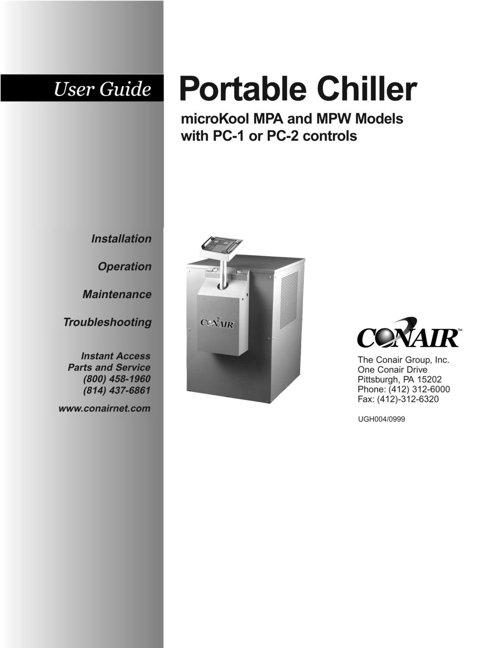
2 Please record your equipment s model and serial number(s) and the date you received it in the spaces provided. It s a good idea to record the model and serial number(s) of your equipment and the date you received it in the User Guide. Our service department uses this information, along with the manual number, to provide help for the specific equipment you installed. Please keep this User Guide and all manuals, engineering prints and parts lists together for documentation of your equipment. Date: Manual Number: UGH00/0999 Serial number(s): Model number(s): DISCLAIMER: The Conair Group, Inc., shall not be liable for errors contained in this User Guide or for incidental, consequential damages in connection with the furnishing, performance or use of this information. Conair makes no warranty of any kind with regard to this information, including, but not limited to the implied warranties of merchantability and fitness for a particular purpose. Copyright 999 THE CONAIR GROUP, INC. All rights reserved
3 INTRODUCTION Purpose of the User Guide How the guide is organized Your responsibility as a user ATTENTION: Read this so no one gets hurt DESCRIPTION What is the microkool chiller? Typical applications How it works: Water-Cooled How it works: Air-Cooled Features Specifications: Water-Cooled Specifications: Air Cooled Freeze protection requirements INSTALLATION Unpacking the boxes Preparing for installation Connecting the proces and water supply lines Connecting the main power Testing the installation Entering setpoint deviation parameters Initial setup Changing temperature units Enabling and disabling passcode protection Selecting the temperature control point (PC- control) Enabling the Auto Start feature (PC- control) Activating SPI communication OPERATION PC- control features PC- control features Positioning the control panel Starting the chiller Entering passcodes Stopping the chiller Using the pumpdown feature (PC- control) Performing an Auto Tune MAINTENANCE Preventative maintenance schedule Cleaning evaporators Cleaning condensers Refilling the tank Checking refrigerant charge TABLE OF CONTENTS UGH00/0999 microkool Portable Chillers i
4 TABLE OF CONTENTS MAINTENANCE (continued) Performing System Tests The Key/Display Test Input Test Output Test Disabling and Enabling Outputs Calibrating Temperature Sensors Logging Operating Hours TROUBLESHOOTING Before Beginning A Few Words of Caution How to Identify the Cause of a Problem DIAGNOSTICS Shut Down Alarms Warning Alarms System Alarms Chiller Will Not Power Up REPAIR Checking and Replacing Fuses Resetting and Replacing Overloads Replacing the Motherboard Replacing the compressor contactor Checking the unloader valve Replacing the freezestat APPENDIX Customer Service Information A- Warranty/Guarantee Information A- microkool SPI commands b- PARTS/DIAGRAMS PC- Wiring Diagram PD- PC- Circuit Board PD- PC- Wiring Diagram PD- PC- Circuit Board PD- Parts Lists ii microkool Portable Chillers UGH00/0999
5 INTRODUCTION Purpose of the User Guide....- How the guide is organized....- Your responsibilities as a user.- ATTENTION: Read this so no one gets hurt UGH00/0999 microkool Portable Chillers -
6 PURPOSE OF THE USER GUIDE This User Guide describes the Conair microkool water-cooled and air-cooled portable chillers and explains step-by-step how to install, operate, maintain and repair this equipment. Before installing this product, please take a few moments to read the User Guide and review the diagrams and safety information in the instruction packet. You also should review manuals covering associated equipment in your system. This review won t take long, and it could save you valuable installation and operating time later. HOW THE GUIDE IS ORGANIZED Symbols have been used to help organize the User Guide and call your attention to important information regarding safe installation and operation. Symbols within triangles warn of conditions that could be hazardous to users or could damage equipment. Read and take precautions before proceeding. Numbers within shaded squares indicate tasks or steps to be performed by the user. A diamond indicates the equipment s response to an action performed by the user. An open box marks items in a checklist. A shaded circle marks items in a list. YOUR RESPONSIBILITY AS AUSER You must be familiar with all safety procedures concerning installation, operation and maintenance of this equipment. Responsible safety procedures include: Thorough review of this User Guide, paying particular attention to hazard warnings, appendices and related diagrams. Thorough review of the equipment itself, with careful attention to voltage requirements, intended uses and warning labels. Thorough review of instruction manuals for associated equipment. Step-by-step adherence to instructions outlined in this User Guide. - INTRODUCTION microkool Portable Chillers UGH00/0999
7 We design equipment with the user s safety in mind. You can avoid the potential hazards identified on this machine by following the procedures outlined below and elsewhere in the User Guide. WARNING: Improper installation, operation or servicing may result in equipment damage or personal injury. This equipment should be installed, adjusted, and serviced by qualified technical personnel who are familiar with the construction, operation and potential hazards of this type of equipment. ATTENTION: READ THIS SO NO ONE GETS HURT All wiring, disconnects and fuses should be installed by qualified electrical technicians in accordance with electrical codes in your region. Always maintain a safe ground. A properly sized conductive ground wire from the incoming power supply must be connected to the chassis ground terminal inside the electrical enclosure. Improper grounding can result in personal injury and erratic machine operation. Do not operate the equipment at power levels other than what is specified on the the equipment serial tag and data plate. Only certified refrigerant technicians should recharge the refrigerant used in this system. WARNING: Electrical shock hazard This equipment is powered by three-phase main voltage, as specified on the machine serial tag and data plate. Always disconnect and lock out the incoming main power source before opening the electrical enclosure or performing non-standard operating procedures, such as troubleshooting or maintenance. Only qualified personnel should perform procedures that require access to the electrical enclosure while power is on. UGH00/0999 microkool Portable Chillers INTRODUCTION -
8
9 DESCRIPTION What is the microkool chiller?.- Typical applications How it works: Water-cooled models How it works: Air-cooled models Features Specifications: Water-cooled...-6 Specifications: Air-cooled Freeze protection requirements UGH00/0999 microkool Portable Chillers -
10 WHAT IS THE MICROKOOL CHILLER? The microkool portable chillers are designed to provide chilled water for industrial applications requiring -hour-aday performance. Operation of air-cooled and water-cooled units differ only in the medium used to remove heat from the refrigerant in the condensers. Water-cooled models use 8 F (9 C) cooling tower water, and are equipped with high efficiency tube-in-tube condensers with water regulating valves. Air-cooled models use 9 F ( C) ambient air and aluminum-fin, copper-tube condensers. Units above. Hp include automatic fan cycling controls. Units are totally self-contained for easy, economical installation. To operate, simply connect the power source, process piping and fill with water or an industrial antifreeze mixture. The standard PC- microprocessor control displays setpoint and actual temperature of the process fluid, and provides SPI communication. Nine operating and fault indicator lights display the status of the chiller components. The enhanced PC- control offers the same features as the standard control plus autostart capabilities, which enables the chiller to start automatically with a timing device or the starting of the primary process machine. TYPICAL APPLICATIONS These chillers are ideal for cooling to maintain process temperatures in an injection molding machine or extruder and wherever you need a small, moveable cooling unit. Capacities range from. to 0. tons. Standard operating setpoints are between 0 F (-7 C) and 6 F (9 C) LWT. Adequate freeze protection is required. Choose water-cooled portable chillers: for maximum capacity and minimal maintenance. when maintaining ambient air temperature is important, such as an air-conditioned environment. when tower water or another inexpensive water source is available. Choose air-cooled portable chillers. when plant water supply is inadequate or limited. when process heat must be extracted and used for space heating. - DESCRIPTION microkool Portable Chillers UGH00/0999
11 Water-cooled models use tube-in-tube heat exchangers to condense the hot, compressed, refrigerant gas from the compressor to a cool liquid. The cool liquid refrigerant passes through a filter/dryer, which protects the system from moisture or other contaminants. An in-line sight glass gives a visual indication of proper refrigerant charge and any dangerous moisture present in the system. The refrigerant passes through a thermal expansion valve, where it expands, cools and is precisely metered into the refrigerant heat exchanger (evaporator). The evaporator removes the heat from the process fluid. HOW IT WORKS: WATER COOLED Typical water-cooled plumbing diagram UGH00/0999 microkool Portable Chillers DESCRIPTION -
12 HOW IT WORKS: AIR COOLED Air-cooled models use aluminum-finned, copper tube condensers to condense the hot, compressed, refrigerant gas from the compressor to a cool liquid. The cool liquid refrigerant passes through a filter/dryer, which protects the system from moisture or other contaminants. An in-line sight glass gives a visual indication of proper refrigerant charge and any dangerous moisture present in the system. The refrigerant passes through a thermal expansion valve, where it expands, cools and is precisely metered into the refrigerant heat exchanger (evaporator). The evaporator removes the heat from the process fluid. Typical air-cooled plumbing diagram - DESCRIPTION microkool Portable Chillers UGH00/0999
13 High Efficiency Compressors All microkool chillers are equipped with quiet Copeland hermetically sealed compressors. Hotgas bypass capacity control is standard, permitting efficient operation with cooling loads as low as % of rated chiller capacities. Molded Plastic Reservoirs Large,thick-walled, insulated polyethylene reservoirs provide corrosion-free operation. Low-water level sensors, external fill ports and level indicators are standard. Control Extension Controls can be extended approximately inches from the control base. FEATURES Water Connections All chilled water and condenser water connections are welded to the structure. Every unit includes bronze chilled water supply and return valves. Corrosion-Free Evaporators On models through 7. Hp, chilled water flows through heavy gauge tube-in-tube evaporators. The water comes in contact with only copper surfaces, eliminating corrosion and scale build-up that can severely reduce chiller efficiency. Low pressure drops, averaging less than psi, result in more flow to the process. Water-cooled unit shown Performance-engineered condensers Water-cooled models are equipped with high efficiency, non-ferrous tube-in-tube condensers and water regulating valves. Air-cooled models have aluminum fin, copper tube condensers. MPA models with compressors above. Hp have automatic fan cycling controls. UGH00/0999 microkool Portable Chillers DESCRIPTION -
14 Pressure (psi) SPECIFICATIONS: MPW (WATER COOLED) 60 HZ PUMP PERFORMANCE CURVES Flow Rate (gpm) MODEL MPW-. MPW- MPW- MPW- MPW- MPW-7. MPW-0 Performance characteristics Capacity {tons} * Compressor Hp {kw}. {.} {.9} {.} {.98} {.7} 7. {.9} 0 {7.} Pump Hp {kw} 0. {0.6} 0.0 {0.7} 0.7 {0.9}. {.}. {.}. {.}. {.} Chilled water flow gpm {l/min}. {.9}. {7.0} 7. {8.} 9.9 {7.}. {.} 8. {68.9}. {8.0} Chilled water pressure psi {bar} 0 {.} 6 {.8} {.} 8 {.6} 8 {.6} 7. {.6} 7 {.} Reservoir capacity gal (l) 0 {7.9} 0 {7.9} 0 {7.9} 0 {} 0 {} 0 {} 0 {} Condenser water flow gpm {l/min}. {6.}.6 {.} 9. {.6}. {7.0}. {.}.8 {86.} 0.6 {6.0} Dimensions inches {mm} A - Height ** {} {} {} 6 {} 6 {} 70 {778} 70 {778} B - Depth (8} {8} {8} 8 {8} 8 {8} 8 {8} 8 {8} C - Width 9 {77} 9 {77} 9 {77} {77} {77} {77} {77} Weight lb {kg} Shipping weight 0 {9} 7 {} 7 {} 00 {8} 00 {8} 0 {67} 0 {67} Installed weight 0 {90} 8 {6} 8 {6} 80 {8} 80 {8} 080 {90} 080 {90} Utility requirements Water connections NPT (female) inches.... Process and condenser water inches.... Voltages running and full load amps run full run full run full run full run full run full run full 08V/ phase/60hz V/ phase/60hz V/ phase/60hz V/ phase/60hz SPECIFICATION NOTES * Based on 0 F (0 C) water temperature (00% water) leaving the chiller, standard pump selections, 8 F (7 C) condenser water psi minimum. Consult factory for other conditions. Standard pump selection. Larger pumps available as options. Based on 0 F water temperature leaving the chiller and 60 F ( C) water temperature returning to the chiller. Pressure at pump discharge. ** Control can be extended upward approximately inches, which may or may not increase the overall height of the unit. Specifications may change without notice. Check with a Conair representative for the most current information. -6 DESCRIPTION microkool Portable Chillers UGH00/0999
15 Pressure (psi) SPECIFICATIONS: MPA (AIR COOLED) 60 HZ PUMP PERFORMANCE CURVES MODEL MPA-. MPA- MPA- MPA- MPA- MPA-7. MPA- Performance characteristics Capacity {tons} * Compressor Hp {kw}. {.}. {.0}. { 79.7} {.98} {.7} 9 {6.7} {8.9} Pump Hp (kw) 0. {0.6} 0.0 {0.7} 0.7 {0.9}. {.}. {.}. {.}. {.} Chilled water flow gpm {l/min}.8 {0.6}. {.9} 6. {.} 8.{.} 9.9 {7.} 6.6 {6.8}. {9.7} Chilled water pressure psi {bar} 0 {.} 6 {.8} {.} 8 {.6} 8 {.6} 7. {.6} 7 {.} Reservoir capacity gal {l} 0 {7.9} 0 {} 0 {} 0{ } 0 {} 0 {} 0. {} Number of condenser fans Condenser fan power Hp {kw} 0.06 {0.07} 0.06 {0.07} 0.06 {0.07} 0.06 {0.07} 0.06 {0.07} 0.0 {0.07} 0.0 {0.07} Condenser air flow ft /min {l/min} 00 {96} 70 {80} 0 {} 7 {000} 7 {000} 00 {0} 800 {96} Dimensions inches {mm} A - Height ** {} 8 {9} 8 {9} 6 {} 6 {} 70 {778} 76 {90} B - Depth {8} {8} {8} 8 {9} 8 {9} 8 {9} 8 {9} C - Width 9 {77} 9 {77} 9 {77} {77} {77} {77} 0{06} Weight lb {kg} Shipping weight 70 {0} 000 {} 000 {} 00 {} 00 {} 00 {6} 600 {76} Installed weight 60 {77} 80 {76} 80 {76} 00 {67} 00 {67} 0 {8} 0 {69} Utility Requirements Water connections NPT (female) inches.... Process water inches.... Voltages running and full load amps run full run full run full run full run full run full run full 08V/ phase/60hz V/ phase/60hz V/ phase/60hz V/ phase/60hz SPECIFICATION NOTES Flow Rate (gpm) * Based on 0 F (0 C) water temperature (00% water) leaving the chiller, standard pump selections, 9 F ( C) ambient air conditions. Consult factory for other conditions. Standard pump selection. Larger pumps available as options. Based on 0 F water temperature leaving the chiller 60 F ( C) water temperature returning to the chiller. Pressure at pump discharge. ** Control can be extended upward approximately inches, which may or may not increase the overall height of the unit. Specifications may change without notice. Check with a Conair representative for the most current information. UGH00/0999 microkool Portable Chillers DESCRIPTION -7
16 FREEZE PROTECTION REQUIREMENTS Temperature, degrees F to Process Set Temperature, degrees F Freeze Protection Requirements by Unit Set Temperature Ethylene Glycol, % by weight Freezing Points of Aqueous Ethylene Glycol Solutions Ethylene Glycol, % by weight -8 DESCRIPTION microkool Portable Chillers UGH00/0999
17 INSTALLATION Unpacking the boxes Preparing for installation Connecting the water supply..- Connecting the main power...- Testing the installation Entering setpoint deviation parameters Initial setup Changing temperature units...-9 Enabling and disabling passcode protection Selecting the temperature control point (PC- Control) Installing the Auto Start feature Activating SPI communication UGH00/0999 microkool Portable Chiller -

18 UNPACKING THE BOXES MicroKool Portable Chillers come fully assembled. Carefully remove the chiller and components from their shipping containers, and set upright. Remove all packing material, protective paper, tape, and plastic. Check inside the electrical enclosure and behind the side panels for accessories or hardware that may have been placed there for shipping. Carefully inspect all components to make sure no damage occurred during shipping, and that you have all the necessary hardware. If damage is found, notify the freight company immediately. Take a moment to record serial numbers and specifications in the blanks provided on the back of the User Guide s title page. The information will be helpful if you ever need service or parts. You are now ready to begin installation. Complete the preparation steps on the next page. - INSTALLATION microkool Portable Chillers UGH00/0999
19 The microkool chiller is easy to install, if you plan the location and prepare the area properly. Position the chiller as close to the process machine as possible. PREPARING FOR INSTALLATION Chiller Process machine Alternate locations Make sure the installation area provides: A three-phase power source supplying the correct current for your chiller model. Check the serial tag on the side of the electrical enclosure for the required voltage, phase, frequency, full load amps, disconnect fuse size and minimum wire connection size. Field wiring should be completed by qualified personnel to the planned location for the chiller. All electrical wiring should comply with your region s electrical codes. A clean, well-ventilated environment. The room temperature should not exceed 0 F ( C) with 9% non-condensing humidity and should not fall below F ( C). Minimum clearance for safe operation and maintenance. Nothing should be placed on top of the unit while the unit is operating. All models require a minimum clearance of ft. around the perimeter for servicing. Models equipped with fans also require unrestricted outlet air flow. A source of water for cooling on water-cooled units. City, tower or chiller water may be used, as long as the supply pressure is at least psi and not more than 8 psi. Install plumbing for process and cooling lines. See the specification tables for the correct line and fitting sizes. Larger line sizes are acceptable as long as they are reduced at the chiller connections. Smaller line sizes are not recommended. UGH00/0999 microkool Portable Chillers INSTALLATION -
20 CONNECTING PROCESS AND WATER SUPPLY LINES Tools for installation: Pipe wrench large enough for a -inch pipe Premium quality Teflon thread sealant The chiller process inlets and outlets must be connected to the plumbing that will circulate the temperature-controlled water or fluid through the process. Cooling water inlets and outlets are connected to the cooling water supply. Remove the shipping pipe plug from the female connections on the back of the chiller. Install pipe to the rear of the chiller. Use appropriately sized male NPT piping for the process connections and the MPW condenser water connections. Process connections (NPT): MPW-. MPW- MPW- MPW- MPW- MPW-7. MPW-0 MPA-. MPA- MPA- MPA- MPA- MPA-7. MPA- in. in. in.. in.. in.. in.. in. Tank level sight glass Condenser water connections (NPT): MPW-. MPW- MPW- MPW- MPW- MPW-7. MPW-0 in. in. in.. in.. in.. in.. in. Pipe and pipe threads must be clean and new. Clean threads with solvent, removing all oil, grease and dirt. Allow the threads to dry before proceeding. Coat the pipe threads with thread sealant. Follow the sealant manufacturer s directions. Connect the male pipe to the appropriate female connection on the back of the unit. Connections are labeled on the chiller. Start by hand until the threads engage, then use a pipe wrench to tighten the connection only enough to prevent leaks. Do not over-tighten! Condenser water connections on MPW models only Condenser water in Condenser water out From Process Tank fill port To Process NOTE: Make sure the chiller tank is full of process fluid before you begin operating. Use a glycol mixture if operating temperatures are below F. See FREEZE PROTECTION REQUIREMENTS. - INSTALLATION microkool Portable Chillers UGH00/0999
21 Before beginning, note the electrical specifications on the nameplate mounted to the side of the unit. The electrical hookup must match these specifications with +/- 0% maximum voltage variance. An improper power supply could damage the unit as well as seriously injure an operator. The electrical hookup also should run through a fused disconnect sized for the nameplate amperage and conforming to Article 0 of the National Electrical Code. WARNING: Electrical shock hazard This equipment is powered by three-phase main voltage. Always disconnect and lock out the main power source before performing any work involving electrical connections. All wiring, disconnects and fusing should conform to your region s electrical codes and should be installed only by qualified personnel. Open the unit s electrical enclosure. Insert the main power wire through the knockout hole in the right side of the enclosure. Secure the power wire with a rubber compression fitting or strain relief. Connect the power wires to the terminals. Connect the three hot wires to L, L, and L on the terminal block. Connect the ground wire to the copper grounding mount. If you have installed a disconnect device, follow the manufacturer s wiring instructions. IMPORTANT! Before initiating power to the unit: Check the system for leaks. Verify that the voltage, phase, frequency, amperage, disconnect fuse and minimum wire size meet the specifications stated on the nameplate mounted on the side of the unit. Verify that resistance to ground on each phase is at least meg ohm. CONNECTING THE MAIN POWER SUPPLY IMPORTANT: Always refer to the wiring diagrams that came with your unit before making electrical connections. The diagrams show the most accurate electrical component information. UGH00/0999 microkool Portable Chillers INSTALLATION -
22 TESTING THE INSTALLATION NOTE: Make sure the chiller tank is full of process fluid before you begin operating. WARNING: Only qualified personnel should perform this procedure. Parts of this test require opening the unit while it is energized. Only qualified personnel who have been trained in the use of electrical testing devices and in avoiding the safety hazards involved in safely troubleshooting this type of equipment should perform this test procedure. Turn on the condenser water supply (MPW units) and check for leaks. If any leaks appear, stop the test and fix the problem before continuing. The water pressure must be at least must be at least PSI at the condenser inlet. Apply power to the unit. Indicator lights on the control panel blink green, then red, to test operation of the LEDs. Setpoint and actual windows will display for three seconds, followed by the software version. The windows then display the factory default setpoint of 0 F (0 C) and the actual temperature. Check the rotation of the pump. Remove the access panel and verify that the pump rotation matches the direction indicated on the rotation stamp on the pump. NOTE: If the rotation is incorrect, stop the test and disconnect power to the unit. Open the electrical enclosure and switch any two of the three power source wires on the terminal block. Return to Step and check rotation again. Replace the access panel. Press the RUN key to start the unit. If everything is working correctly: The RUN/STOP light turns green. The pump begins operating. The compressor turns on after seconds, if the actual temperature is above the setpoint. Normal operation begins. The unloader valves turn on, if the actual temperature is below setpoint. The compressor remains active until the actual temperature is 6 F below the setpoint. The test is over. Proceed to initial setup if the unit operated normally; refer to the TROUBLESHOOTING section if it did not. -6 INSTALLATION microkool Portable Chillers UGH00/0999
23 You can establish a normal operating range around the process temperature setpoint using the high and low deviation parameters. If the process temperature exceeds the high deviation limit, or falls below the low deviation limit for longer than minutes, the chiller will alert you to the unacceptable temperature variation with an alarm light. These temperature deviation limits will adjust automatically relative to the process temperature setpoint. The factory default setting is the process temperature setpoint ± 0 F (6 C). This parameter is adjustable to establish a narrower or wider acceptable temperature range for normal operation. You cannot set the Low Deviation below the factory-set Low Safety temperature. The High Deviation cannot be set to exceed the factory-set High Safety temperature. ENTERING SETPOINT DEVIATION PARAMETERS FACTORY DEFAULT SETTINGS Model MPW MPA Process Setpoint 0 F (0 C) 0 F (0 C) High Safety 7 F ( C) 7 F ( C) Low Safety 0 F (- C) 0 F (- C) To change the temperature deviation settings: Press the Setpoint Select button to select the deviation parameter you want to change. Use the and setpoint buttons to enter the deviation temperature. The setting is stored in memory even when the power is turned off. The recommended setting is ± -0 F. NOTE: If you enabled passcode protection, you must enter the passcode to change this parameter. See ENABLING AND DISABLING PASSCODE PROTECTION. Too enter the passcode: Hold down the Setpoint Select button for seconds. When the control displays PaS, use the setpoint adjustment buttons to enter the passcode. Press the Setpoint Select button again. If the correct passcode was entered the controller will display ACC PAS for seconds. If the passcode was incorrect, the controller will display rej PAS (rejected passcode). Access to system parameters remain until power is cycled or the RUN or STOP button is pressed. UGH00/0999 microkool Portable Chillers INSTALLATION -7
24 INITIAL SETUP WARNING: Electric shock hazard This equipment is powered by high voltage. Always disconnect and lock out the main power source before opening the unit or the electrical enclosure to modify factory settings. Failure to disconnect and lock out the main power source can result in severe personal injury. The factory-set parameters and operating modes will satisfy most applications. But you can change some settings and enable or disable features as needed. You can modify the parameters for high and low process temperature deviation warnings from the control panel. See SETTING SETPOINT DEVIATION PARAMETERS. Dip switches on the motherboard inside the PC- and PC- electrical enclosure allow you to: Select the units of measure for temperature displays. Enable password protection. Enable the Auto Tune. Enable the Auto Start feature. Enable the Test Mode. Select the source point of temperature control NOTE: Dip switch 7 must be ON and dip switch 8 must be OFF for the chiller to work. Do not change the factory setting of these two dip switches. Dip switch Configuration No. OFF ON Display units in F Display units C Auto Tune disabled Auto Tune enabled Passcode protect Password reset/modify * Auto Start disabled Auto Start enabled * Control point protect Control point source select 6 Test Mode disabled Test mode enabled 7 Controller type selection Controller type selection 8 Controller type selection Controller type selection * Available only on PC- control models. Switch 7 must be ON, and switch 8 must be OFF. Do not change the settings of these two switches. To change the dip switch settings, see the appropriate topic on the following pages. -8 INSTALLATION microkool Portable Chillers UGH00/0999
25 WARNING: Electric shock hazard This equipment is powered by high voltage. Always disconnect and lock out the main power source before opening the unit or the electrical enclosure to modify factory settings. Failure to disconnect and lock out the main power source can result in severe personal injury. CHANGING TEMPERATURE UNITS The temperature units are factory-set as degrees Celsius or degrees Fahrenheit, as specified when the unit was ordered. When the chiller is on, the indicator lights to the right of the Actual temperature display on the control panel will show which temperature unit has been set. To change this setting, move Dip Switch on the control circuit board. Disconnect and lock out main power to the chiller. Open the electrical enclosure. Change Dip Switch to: OFF for F ON for C Close the electrical enclosure and restore main power to begin operating. UGH00/0999 microkool Portable Chillers INSTALLATION -9
26 ENABLING AND DISABLING PASSCODE PROTECTION WARNING: Electric shock hazard This equipment is powered by high voltage. Always disconnect and lock out the main power source before opening the unit or the electrical enclosure to modify factory settings. Failure to disconnect and lock out the main power source can result in severe personal injury. The PC- and PC- controls provide the ability to protect system parameters from unauthorized changes during normal operating mode. When system passcode protection is enabled, the following parameters cannot be changed unless you enter the correct passcode: The Process Setpoint High Deviation Alarm Setpoint Low Deviation Alarm Setpoint Baud Rate selection for serial communications Address selection for serial communications When the unit is turned on for the first time, passcode protection is disabled. To enable passcode protection: Disconnect and lock out main power to the unit. Open the electrical enclosure. Set dip switch to ON and switches and 6 to OFF Close the electrical enclosure and restore power to the unit. Press any button when the control displays Pas rst (Passcode Reset). The control will display the last passcode used. Select a new passcode using the and setpoint adjustment buttons. Stop pressing the setpoint buttons when the passcode you want appears in the setpoint display window. Selecting OFF as the passcode will disable the passcode feature. -0 INSTALLATION microkool Portable Chillers UGH00/0999
27 ENABLING AND DISABLING PASSCODE PROTECTION 7 Press the RUN button to save the passcode. The control will display Pr OFF to prompt you to remove power to the unit IMPORTANT: If RUN is not pressed, the new passcode will not be saved. Turn off power to the unit. Disconnect and lock out the main power supply. Open the electrical enclosure. Set dip switch to OFF. Close the electrical enclosure and restore power to the unit. A passcode now is required to change system parameters. Disabling Passcode Protection To disable passcode protection and allow universal access to system parameters: Follow Steps through in the previous section on enabling passcode protection. Hold down the setpoint adjustment button to select OFF as the new passcode. Follow steps 7 through in the previous section UGH00/0999 microkool Portable Chillers INSTALLATION -
28 SELECTING THE TEMPERATURE CONTROL POINT (PC- CONTROL ONLY) WARNING: Electric shock hazard This equipment is powered by high voltage. Always disconnect and lock out the main power source before opening the unit or the electrical enclosure to modify factory settings. Failure to disconnect and lock out the main power source can result in severe personal injury. PC- microprocessors control the process temperature based upon the average of the temperatures recorded at the supply (to process) and return (from process) thermocouples. The PC- microprocessor allows you to select how the unit will measure and control the process temperature. The control point can be selected as the supply, the return or the average of the the two temperatures. To select the control point source on units with PC- control: 6 Disconnect and lockout power to the unit. Open the electrical enclosure. Set dip switches and 6 to the OFF position. Set dip switch to the ON position. Close the electrical enclosure and restore power to the unit. Press any button when the control displays Cnt Pt. The controller will display Sel CnP and flashes the LED for the current control point Select a new control point using the Display button. Stop pressing the select button until the indicator light next to the control point you want illuminates. - INSTALLATION microkool Portable Chillers UGH00/0999
29 SELECTING THE TEMPERATURE CONTROL POINT (PC- CONTROL ONLY) 8 Press the RUN button to save the control point. The control will display Pr OFF to prompt you to remove power to the unit. 9 0 IMPORTANT: If RUN is not pressed, the new control point source will not be saved. Turn off power to the unit. Disconnect and lock out the main power supply. Open the electrical enclosure. Set dip switch to OFF. Close the electrical enclosure and restore power to the unit. The chiller will now control the process temperature based on actual temperatures recorded at the new control point source UGH00/0999 microkool Portable Chillers INSTALLATION -
30 INSTALLING THE AUTO START FEATURE (PC- CONTROL ONLY) WARNING: Electric shock hazard This equipment is powered by high voltage. Always disconnect and lock out the main power source before opening the unit or the electrical enclosure to modify factory settings. Failure to disconnect and lock out the main power source can result in severe personal injury. If you have a PC- microprocessor control, you can automatically start and stop the chiller from a remote switching or timing device that has power contacts rated 0VAC, such as the process machine control. Wiring the device to the chiller is accomplished through a dry contact to the appropriate terminals on the motherboard. After wiring the device to the unit, Auto Start must be enabled by configuring a dip switch on the motherboard. Disconnect and lockout power to the unit. Open the electrical enclosure. Punch a small hole in the left side of the electrical enclosure. The hole must be large enough to accommodate conduit for the power contact wires from your switching or timing device. Insert the two power leads from the device through the conduit into the electrical enclosure. Device contacts AC IN AC IN + AC OUT AC OUT + 6 IMPORTANT: Always refer to the wiring diagrams that came with your unit before making electrical connections. The diagrams show the most accurate electrical component information. Connect the 0VAC device contact wires to the Auto Start terminals. Make sure terminals are screwed tight. F LLS/WPS LLS/WPS AUTOSTART AUTOSTART HPS/LPS HPS/LPS OPS OPS FSTAT FSTAT - INSTALLATION microkool Portable Chillers UGH00/0999
31 Set dip switch to the ON position. Close the electrical enclosure and restore power to the unit. INSTALLING THE AUTO START FEATURE (PC- CONTROL ONLY) When Auto Start is enabled: The Auto Start indicator light flashes to indicate that the Chiller can start at any time. The chiller will start whenever the remote switching or timing device sends a signal to start processing. The Auto Start indicator light is on whenever the chiller is under the control of the remote device. To disable Auto Start: Repeat steps, and 7, setting dip switch to the OFF instead of the ON position. UGH00/0999 microkool Portable Chillers INSTALLATION -
32 ACTIVATING SPI COMMUNICATION NOTE: To disable SPI, use the setpoint or arrow to select Address. Press the arrow until OFF is displayed in the setpoint window. See the APPENDIX for additional SPI programming information. MicroKool portable chillers provide SPI compatible support for RS-8 serial communications with a host machine. You can use SPI communication to change or monitor the: Process temperature setpoint High and low temperature deviation alarms Process status (run and alarm conditions) Machine status Machine status Actual temperature to process Actual temperature from process To use the SPI communication option, you must connect the chiller to the host machine and set the communication baud rate and node address using the setpoint select and adjustment buttons on the control panel. Connect the host machine to the chiller. Plug the male DB9 connector into the serial communications port on the chiller. Apply power to the chiller. Enter the passcode, if necessary. Hold the Setpoint Select button for seconds. When the control displays PaS, use the setpoint adjustment buttons to enter the passcode. Enter the node address. Press the Setpoint Select button to choose Address. Then press the setpoint or arrow until the address you want appears in the setpoint display. The address may be set to any number from to (a hexadecimal integer between 0 and FE), as long as that number has not been assigned to another machine connected to the same network. Set the baud rate to,, 8 or 96. The chiller must be set to send and receive data at the same baud rate as the host machine. Press the setpoint or arrow until the baud rate you want appears in the setpoint display window. = 00 bps 8 = 800 bps = 00 bps 96 = 9600 bps The green SPI status light on the control panel should flash when the unit is communicating. The LED will turn red, indicating an alarm, if SPI communication is not properly set up. -6 INSTALLATION microkool Portable Chillers UGH00/0999
33 OPERATION PC- control features PC- control features Positioning the control panel..- Entering a passcode Starting the chiller Stopping the chiller Using the PC- pumpdown feature Performing an Auto Tune UGH00/0999 microkool Portable Chiller -
34 PC- CONTROL FEATURES All normal operating functions can be controlled from the microkool PC- control panel. Setpoint display The Setpoint display shows the setpoints entered for fluid temperature, high and low temperature deviation alarms, the SPI baud rate, and the SPI address. Setpoint and Actual value display windows also display some alarm codes and setup instructions. Run/Stop Press the RUN button to start normal operation. Press STOP to stop the unit. = Running (green) = Stopped (red) = Alarm (red, flashing) Actual values display The green window displays the temperature at the middle of the process. This is calculated as an average of the process fluid temperatures at the chiller inlet and outlet. The lights indicate whether the temperature is in degrees Fahrenheit or Celsius. See the INSTALLATION section for instructions on how to change the temperature units. Status lights The lights indicate the operating status of the listed components. Except in Test Mode, the lights indicate: = Off or inactive = On or active (green) = Alarm condition (red) Test Mode is used for testing displays, keys and input/output functions. When test mode is enabled, normal operation is disabled. Setpoint Select button Press repeatedly until a green light appears next to the parameter you want to program or view. NOTE: Default settings for the deviation setpoints are: High = setpoint + 0 F Low = setpoint - 0 F A warning alarm occurs (indicator light red) whenever the actual temperature is outside this setpoint range for more than minutes. Recommended setting: ± -0 F. Alarm Press to acknowledge the alarm light and silence the optional audible alarm. The alarm light will flash until the cause of the alarm condition is fixed. See Troubleshooting for alarm descriptions and remedies. = Test Mode off = Test Mode on (red); unit disabled Setpoint adjustment buttons Press or to enter the process temperature setpoint, SPI parameters and passcodes. Press to increase a value. Press to decrease a value. TIP: Press and hold the button for faster scrolling speed. NOTE: Passcode protection prevents accidental or unauthorized changes to all operating parameters. If passcode protection has been enabled, you must enter the correct passcode to change the process temperature setpoint. - OPERATION microkool Portable Chillers UGH00/0999
35 All normal operating functions can be controlled from the microkool PC- control panel, including the optional pumpdown feature. Setpoint display The Setpoint display shows the setpoints entered for fluid temperature, high and low temperature deviation alarms, the SPI baud rate, and the SPI address. Setpoint and Actual value display windows also display some alarm codes and setup instructions. Run/Stop Press the RUN button to start normal operation. Press STOP to stop the unit. = Running (green) = Stopped (red) = Alarm (red, flashing) PC- CONTROL FEATURES Actual values display The green window displays the temperature at the middle of the process. The control point for this temperature is selectable as the temperature at the supply outlet, return inlet or the average of the two temperatures. The lights indicate whether the temperature is in degrees Fahrenheit or Celsius. See the INSTALLATION section for instructions on how to change the temperature units. Status lights The lights indicate the operating status of the listed components. Except in Test Mode and Auto Start, the lights indicate: = Off or inactive = On or active (green) = Alarm condition (red) Test Mode is used for testing displays, keys and input/output functions. When test mode is enabled, normal operation is disabled. Setpoint Select button Press repeatedly until a green light appears next to the parameter you want to program or view. NOTE: Default settings for the deviation setpoints are: High = setpoint + 0 F Low = setpoint - 0 F A warning alarm occurs (indicator light red) whenever the actual temperature is outside this setpoint range for more than minutes. Recommended setting: ± -0 F. Setpoint adjustment buttons Press or to enter the process temperature setpoint, SPI parameters and passcodes. Press to increase a value. Press to decrease a value. TIP: Press and hold the button for faster scrolling speed. Alarm Press to acknowledge the alarm light and silence the optional audible alarm. The alarm light will flash until the cause of the alarm condition is fixed. See Troubleshooting for alarm descriptions and remedies. Pumpdown On/Off The Pumpdown feature prevents refrigerant migration. The compressor turns on and off as needed to store refrigerant in the condenser. Display Select button Press repeatedly until a green light appears next to the parameter you want to program or view. = Test Mode off = Test Mode on (red); unit disabled Auto Start allows you to start and stop the chiller from a remote switching or timing device, such as the processing machine control. This feature can only ben enabled by configuring a dip switch on the control motherboard. = Disabled; Auto Start not available = Enabled (flashing green); unit can start any time = On and under control of the remote device UGH00/0999 microkool Portable Chillers OPERATION -
36 POSITIONING THE CONTROL PANEL CAUTION: Improper use of the swiveling control panel can damage the unit. Do not rotate the control panel 60 degrees. This will twist and possibly damage the control wiring and connections to the motherboard in the electrical enclosure. Do not use the control panel handles or control cables to move the chiller. The handles are designed only for orientation of the control panel. Do not mount the detachable PC- control panel to a hot surface. The control panel on microkool chillers can be swiveled, raised and lowered to provide easy viewing and access. The PC- control panel also can be mounted up to 0 feet from the unit, using a remote control cable and the magnetic back on the back of the panel. To raise and swivel the control panel: Grasp the black control panel handles, and pull upward. Use the handles to rotate the control panel. Do not rotate the panel 60 degrees. To lower the control panel: Grasp the black control panel handles, and rotate the control until it is aligned with the unit. Do not rotate the panel 60 degrees. Gently push down on the handles until the control panel is flush with the unit. To detach the PC- control panel: The PC- control panel may be removed and mounted up to 0 feet from the unit. Do not stretch the cable. The cable is available in various lengths so that you can order the appropriate cable for your installation. Grasp the black control panel handles and pull upward. Use the magnetic back to mount the control panel in the remote location. Connect the remote-mounted control to the unit with the cable provided. - OPERATION microkool Portable Chillers UGH00/0999
37 ENTERING A PASSCODE PC- and PC- controls have a security feature that prevents accidental or unauthorized changes to the setpoint temperature, high and low deviation limits, SPI address, and baud rate. If passcode protection is enabled, you must enter the correct passcode to change these parameters. To enter the passcode: Press and hold the Setpoint Select button for seconds. The control will display PaS to indicate a passcode is needed. Press the Select button until the correct passcode appears in the display. Press again to enter the passcode. If the passcode is correct, the control displays ACC PAS for seconds. If the passcode is incorrect, the control displays rej PAS (rejected passcode). Press Setpoint want to change. to select the parameter you You will have access to the system parameters until: The power is cycled off and on. The RUN or STOP button is pressed. No key has been pressed for 0 seconds. NOTE: Pressing the STOP or RUN key while you are entering a passcode will abort the passcode entry sequence UGH00/0999 microkool Portable Chillers OPERATION -
38 STARTING THE CHILLER IMPORTANT: If you are operating the chiller for the first time since installation, you should perform an Auto Tune after two hours of normal operation. You should perform the Auto Tune periodically to ensure that the control correctly calculates how much heat and cooling should be applied to maintain the process setpoint. See PERFORMING AN AUTO TUNE. Before starting the chiller, verify that the system has been installed correctly for your application. See the INSTALLATION section. If Passcode Protection has been enabled, you must enter the correct passcode before you can change or enter any of the operating parameters, including the setpoint. Turn on main power to the chiller at least hours before you want to begin processing. This allows time for crankcase heater to evaporate liquid refrigerant migrating in the compressor. When power is turned on: The compressor crankcase heater turns on. Indicator lights blink green, then red. Setpoint and actual windows will display for three seconds, followed by the software version. The windows then display the previously entered setpoint and the actual temperature. 6 Make sure the chiller tank is full of fluid. Turn on the water supply to the chiller (MPW). The supply must be at least psi. Check for leaks in the condenser water and process fluid lines before continuing. Enter the passcode, if necessary. Hold the Setpoint Select button for seconds. When the control displays PaS, use the setpoint adjustment buttons to enter the passcode. Press the Setpoint Select button again. Enter the temperature setpoint. Press the Setpoint Select button until the green light appears next to Temperature. Press to increase or to decrease the temperature setting. Run Press to start normal operation. The RUN/STOP light turns green. The pump begins operating. The compressor turns on after seconds, if the actual temperature is above the setpoint. Normal operation begins. The unloader valves turn on if the actual temperature is below setpoint. The compressor remains active until the actual temperature is 6 F below the setpoint. If the Alarm light turns on, press to silence the optional audible alarm. Then see the TROUBLESHOOTING section. -6 OPERATION microkool Portable Chillers UGH00/0999
39 WARNING: Electrical shock hazard Before attempting maintenance of any kind on the chiller, you must stop the unit; disconnect and lockout the main power supply. STOPPING THE CHILLER You must shut down the chiller whenever you: Change water or process hookups. Shut down the process machine. Run the unit s diagnostic tests. Perform routine or preventative maintenance. See an alarm condition that requires troubleshooting. Relocate, ship or store the unit. To shut down the unit: Press Stop. Disconnect the power supply if you have shut down to service or repair the chiller. If you have shut down the chiller for relocation or storage, drain all fluid from the unit; disconnect the power supply; and disconnect all process and water connections. In shipment or storage, the chiller can withstand an environment between -0 F (-0 C) and 0 F (6 C) with 9% relative humidity non-condensing. The microkool must be running to use this feature. Press the button to turn on Pumpdown. The green Pumpdown light will flash, indicating the feature is ready to start when needed. When Pumpdown is needed, the compressor runs occasionally to pump refrigerant to the condenser. When Pumpdown is running, the green light remains on but does not flash. Press the Pumpdown. button again to turn off USING THE PUMPDOWN FEATURE (PC- CONTROL ONLY) UGH00/0999 microkool Portable Chillers OPERATION -7
40 PERFORMING AN AUTO TUNE WARNING: Electric shock hazard This equipment is powered by high voltage. Always disconnect and lock out the main power source before opening the unit or the electrical enclosure to modify factory settings. Failure to disconnect and lock out the main power source can result in severe personal injury. You should perform an Auto Tune after the first two hours of operation and whenever process variables change (changes in condenser water pressure, piping or molds; large ambient swings; new setpoint temperature) to ensure that the control continues to obtain good approximations of the PID constants used to compensate for the thermal lag of the system. To ensure a successful Auto Tune, verify that: The Auto Tune feature has been enabled. Auto Tune is enabled or disabled via dip switch on the motherboard. The process value is stable. A fluctuating process value will fool the software into making inaccurate tuning decisions. The software waits minutes for the process value to stabilize before it starts the Auto Tune process. If the process value still fluctuates after minutes, the Auto Tune terminates and the control displays the At ti error. The control is in STOP mode and the process value is in ambient temperature. This allows the software to obtain good approximations of process parameters, which are critical for performing an accurate tune. If this requirement is not met, then a good tune cannot be guaranteed. The setpoint/process deviation is at least F. If the absolute value of setpoint - process temperature is not greater than or equal to F, the Auto Tune will terminate. The control will display an At dev error. Press Stop to shut down the chiller. Disconnect and lock out main power to the unit. Enable Auto Tune. Open the electrical enclosure. Set dip switch to ON. Close the electrical enclosure and restore power to the unit Restore power to the unit. -8 OPERATION microkool Portable Chillers UGH00/0999
41 PERFORMING AN AUTO TUNE Run Press and (the Setpoint Select button) simultaneously to begin the Auto Tune. The Actual display will flash At and the current process temperature to indicate that an Auto Tune is underway. If Auto Tune is successful, the controller automatically starts controlling using the new PID parameters. If you press the STOP button or a fault occurs during the Auto Tune, the control enters stop mode and Auto Tuning immediately terminates. The actual display stops flashing At. If a fault occurred, the control will display the appropriate error message. ERROR MESSAGE At dev ERROR DESCRIPTION Insufficient setpoint/process deviation. If the absolute value of (setpoint - process value) is less than F. The Auto Tune cannot be started until the temperature difference is at least F. At At ti bad Auto Tune timed out. Auto Tune will time out if a stable process value cannot be obtained minutes into the tune, or if the tuning process takes longer than 0 minutes. If this error occurs, verify that you followed every requirement under To ensure a successful Auto Tune and perform a second tune. Invalid PID constants were generated. The most likely causes of this error is a tune started inappropriately or an external element (i.e., loose thermocouple) that upset the process while tuning was in progress. Verify that you followed every requirement under To ensure a successful Auto Tune and perform a second tune. UGH00/0999 microkool Portable Chillers OPERATION -9
42
43 MAINTENANCE Maintenance schedule Cleaning evaporators Cleaning condensers Filling the tank Checking refrigerant charge...-6 Performing system tests Key/Display Test Input Test Output Test Disabling or enabling output monitors Calibrating temperature sensors Logging operating hours UGH00/999 microkool Portable Chillers -
44 PREVENTATIVE MAINTENANCE SCHEDULE To maintain the best performance, we recommend the following maintenance schedule. Whenever process variables change Perform an Auto Tune. The Auto Tune ensures that the control continues to obtain good approximations of the PID constants used to compensate for the thermal lag of the system.. You should perform an Auto Tune after the first two hours of operation and whenever the process changes, such as after a mold change; installation of different pipe sizes; or change in process setpoint. See PERFORMING AN AUTO TUNE in the OPERATION section. Weekly, or as often as needed Check for leaks in condenser and process lines. Before and during operation, you should inspect the unit and all plumbing lines for leaks. If a leak develops, stop the chiller and repair it. Keep the unit and the area around it clean. Check for and remove lint, dust or other obstructions on the unit, especially around air intake areas. Keep the floor around the unit dry. If you notice a decrease in efficiency over time, check all heat transfer surfaces of the evaporator and condenser for fouling. See CLEANING EVAPORATORS AND CONDENSERS. Check the process fluid level. Check the level indicator on the back of the unit to make sure the tank contains an adequate amount of process fluid. Refill as needed. See REFILLING THE TANK. Monthly, or as often as needed. Check the refrigerant charge. A sight glass located between the condenser and evaporator indicates refrigerant pressure. See CHECKING REFRIGERANT CHARGE. Clean all external surfaces. Surfaces fouled by dust, dirt, slime, minerals and other contaminants will decrease performance. Wipe all external surfaces, paying particular attention to heat transfer surfaces. Clean the air-cooled condenser surfaces if you find dirt or clogging. Check the water treatment system. If you use a water treatment system for the water-cooled condenser or the process fluid circuit, maintain the proper chemical levels and follow the recommendations of your water treatment specialist. - MAINTENANCE microkool Portable Chillers UGH00/0999
45 Quarterly (every months) Inspect power cords, wires and electrical connections. Check for loose or frayed wires, burned contacts, and signs of overheated wires. Check exterior power cords to the main power source and from the electrical box to the pump and heating elements. Check the ground wire and thermocouple connections. Replace any wire that appears damaged or has worn or cracked insulation. PREVENTATIVE MAINTENANCE SCHEDULE Annually (every months) Test and calibrate the unit s control systems. The chiller s Test Mode checks the operation of displays, control buttons, inputs and outputs. You can also calibrate the supply and return thermocouples. See PERFORMING SYSTEM TESTS in this section. Clean all surfaces that come in contact with water. Minerals and other water contaminants cause heattransfer surface fouling and decrease performance, especially in the water-cooled chiller s condenser. Clean all water-cooled condenser surfaces. The refrigerant side does not foul because the refrigerant acts as a solvent and operates in a closed filter cycle. See CLEANING EVAPORATORS AND CONDENSERS in this section. WARNING: Improper servicing may result in equipment damage or personal injury. This equipment should be installed, adjusted, and serviced by qualified technical personnel who are familiar with the construction, operation and potential hazards of this type of equipment. All wiring, disconnects and fuses should be installed by qualified electrical technicians in accordance with electrical codes in your region. Only certified refrigerant technicians should recharge the refrigerant used in this system. Always disconnect and lock out the incoming main power source before opening the electrical enclosure or performing non-standard operating procedures, such as troubleshooting or maintenance. Only qualified personnel should perform procedures that require access to the electrical enclosure while power is on. UGH00/0999 microkool Portable Chillers MAINTENANCE -


46 CLEANING EVAPORATORS Minerals and other water system contaminants produce deposits, scales, slime, or algae on the heat-transfer surfaces exposed to water. Fouled surfaces decrease cooling capacity. We recommend that you consult a water treatment specialist to develop a treatment program that will minimize fouling. To clean the evaporator: Consult a water treatment specialist for recommendations on the best chemicals to use to remove contaminants from the evaporator and process fluid circuit surfaces that come in contact with water. Thoroughly flush cleaning chemicals from the evaporator and all water-contact surfaces in the process fluid circuit. Fluid tank Evaporator CLEANING CONDENSERS For water-cooled condensers: You should consult a water treatment specialist for recommendations on the best chemicals to use to remove contaminants from the condenser. Thoroughly flush chemicals from the condenser before resuming operation. For air-cooled condensers: The air-cooled condensers can accumulate dirt and clog quickly if it is run in a dusty or dirty environment. A clogged condenser increases refrigerant pressure, lowers performance and may cause the fan motors and compressor to overheat. Clean dirty coil surfaces with a soft brush. Brush and rinse in the direction of the fins to prevent bending the fins. Rinse with cool water or a commercial coil cleaner. Condenser coils - MAINTENANCE microkool Portable Chillers UGH00/0999
47 The process fluid, which can be water or a glycol mixture, is held in a tank inside the unit. This tank should be kept at least three-quarters full of the process fluid. You can check the fluid level in the tank using the sight glass on the back of the chiller. To fill the reservoir: Locate the fill port at the back of the chiller. Refill the tank. Monitor the level using the sight glass on the back of the unit. Because chillers can use pure water or glycol mixtures, make sure you are adding the correct fluid for your application. Tank level sight glass Tank fill port REFILLING THE TANK IMPORTANT: Do not use deionized water or glycol mixtures containing additives in a this chiller. Softened water or glycol mixtures with additives, such as automotive fluids, can damage the chiller. Glycol/water process loop mixtures should use industrial-grade ethylene glycol only. Use a glycol mixture if operating temperatures are below F See FREEZE PROTECTION REQUIREMENTS in the DESCRIPTION section for information on glycol mixtures. UGH00/0999 microkool Portable Chillers MAINTENANCE -


48 CHECKING REFRIGERANT CHARGE All chillers are fully charged with refrigerant at the factory. Your chiller mode s nameplate identifies the type and amount of total refrigerant charge required. While the unit is running, check the refrigerant charge through the sight glass located between the evaporator and the condenser. Use a flashlight to look at the liquid-line sight glass. Under full-load conditions, the sight glass should be clear. Under low-load conditions, when the hot-gas bypass valves are operating, bubbles may be visible in the sight glass. This is normal. If the charge is low, recharge the system. Contact a certified refrigerant technician to recharge or replace refrigerant. This procedure should be performed only be a qualified technician. -6 MAINTENANCE microkool Portable Chillers UGH00/0999
49 The microkool portable chillers provide a Test Mode that tests displays and keys on the control panel, as well as inputs and outputs. The Test Mode also allows calibration of the supply and return line thermocouples. PERFORMING SYSTEM TESTS System tests and calibration should be performed annually. To enable Test Mode: Press Stop to shut down the chiller. Disconnect and lock out main power to the unit, then open the electrical enclosure. Set dip switches and to OFF. Set dip switch 6 to ON. Close the electrical enclosure and restore power to the unit. The control displays tst. The Test Mode LED lights Press any button to display the first test menu. Test mode provides the following menus: Key/Display Test Input Test Output Test Calibration Total Operating Hours Output Monitor Enable/Disable After performing each test, hold the Setpoint for seconds to index to the next test menu. The procedure for each test is described on the following pages. IMPORTANT: All normal operating functions are disabled while Test Mode is enabled. To return to normal operation, you must disable Test Mode. To disable Test Mode, repeat steps through, setting dip switch 6 to OFF instead of ON. UGH00/0999 microkool Portable Chillers MAINTENANCE -7
50 KEY/DISPLAY TEST The Key/Display Test verifies the function of displays, LEDs and buttons on the control panel. Enable Test Mode. Press any key. If necessary, index to the Key/Display menu. 6 Press and hold the Setpoint key for seconds to index to each test menu until the controller displays dsp. Press any key to clear all displays. Repeatedly press any key to test displays. With each key press, a new segment of all six 8-segment LEDs and a select group of LED indicator lights will illuminate. Exit the test and enter the next test. Press and hold the Setpoint key for seconds to exit and index to the next test. -8 MAINTENANCE microkool Portable Chillers UGH00/0999
51 The Input Test verifies the function of inputs available on the various models of the microkool chiller. Not all inputs are used on all models. The performance evaluation of the inputs is based on the voltage sensing device (VSD). Connect all inputs to the system. Press any key to display the first test menus. Select the Input Test menu. Press and hold the Setpoint key for seconds to index to each test menu until the controller displays InP. INPUT TEST Repeatedly press and release any key to test. With each key press and release, the left display will indicate the number of the input being tested (v, v, v, etc.). The right display indicates either for voltage present or O for an absence of voltage. Only inputs that are actually used by the particular model will be tested. Exit the test and enter the next test. Press and hold the Setpoint key for seconds to exit and index to the next test. UGH00/0999 microkool Portable Chillers MAINTENANCE -9
52 OUTPUT TEST The Output Test verifies the function of outputs available on the various models of microkool chillers. Not all outputs are used on all models. The performance evaluation of the inputs is based on the output monitors (OM). Connect all outputs to the system. IMPORTANT: Testing each output requires the firing of the associated solid state relay. Make sure an output device is connected to the controller, otherwise the test result will be erroneous. Enable Test Mode. Press any key to display the first test menus. Select the Output Test menu. Press and hold the Setpoint key for seconds to index to each test menu until the controller displays out. Repeatedly press and release any key to test. With each key press and release, the left display will indicate the number of the output being tested (os= OM; os = OM; etc.). The right display indicates either for a good output or O for a failed output. 6 Only outputs that are actually used by the particular model will be tested. Exit the test and enter the next test. Press and hold the Setpoint key for seconds to exit and index to the next test. -0 MAINTENANCE microkool Portable Chillers UGH00/0999
53 All output monitors on the microkool chiller can be enabled or disabled permanently through the OM Enable/Disable Menu in Test Mode. You need to use this feature if you have replaced the motherboard, or if dip switches 7 and 8 have been changed erroneously. This will enable any required output monitors that were disabled and give fuse failures. Enable Test Mode. Press any key to display the first test menus. DISABLING OR ENABLING OUTPUT MONITORS 6 Select the OM Enable/Disable menu. Press and hold the Setpoint key for seconds to index to each test menu until the controller indicates os in the actual display and the status of the selected output in the Select display. Press the Setpoint or key to change the status. Each press of the key changes the output status from ON to OFF or OFF to ON. Press the Setpoint to select the next output. Repeat Step to change the status of the output, or press any key to continue indexing through the outputs. Save changes and exit the output menu. Press and hold the Select key for seconds to save the changes and exit. UGH00/0999 microkool Portable Chillers MAINTENANCE -
54 CALIBRATING TEMPERATURE SENSORS Special Tools Needed: thermocouple calibrator The microkool chillers use thermocouples to sense the temperature in the return and supply process lines. These thermocouples should be calibrated annually, or when a new thermocouple is installed, to ensure correct operation. The chiller s Calibration Mode provides zero and span calibration of both the supply and return line thermocouples. You access the Calibration Mode while in Test Mode. Enable Test Mode. See PERFORMING SYSTEM TESTS. Press any button to display the first test menu. Select the Calibration Mode menu. Press and hold the Setpoint key for seconds to index to each test menu until the controller indicates SC.L in the Actual display. Release the Setpoint key. You are now in calibration mode. Each press and release of this key will exit the current calibration and start the next calibration. The table below lists the calibrations that will be performed. SETPOINT ACTUAL CALIBRATION DISPLAY DISPLAY Zero Calibrate Supply Sensor F (0 C) SC.L Zero Calibrate Return Sensor F (0 C) rc.l Span Calibrate Supply Sensor 0 F (66 C) SC.H Span Calibrate Return Sensor 0 F (66 C) rc.h Using the thermocouple calibrator, apply the appropriate temperature to the control input. - MAINTENANCE microkool Portable Chillers UGH00/0999
55 6 Press the up key to begin calibrating. The controller displays the name of the current calibration (examples: SC.L; rc.l; 0 SC.H; or 0 rc.h). CALIBRATING TEMPERATURE SENSORS Wait until the control displays don or bad. A don message in the Setpoint display indicates the calibration was successful. A bad message in the Setpoint display indicates a bad calibration. NOTE: The original calibration value stored in EEProm can be restored for the current calibration by pressing the STOP key at any time. Press Select to start the next calibration. Pressing and releasing the Select key at the end of a calibration tells the controller to perform the next calibration. Exit Calibration Mode. Press and hold the Select key for seconds to exit the Calibration Mode. You can now proceed to the next test in Test Mode, or disable Test Mode and resume normal operation. TO DISABLE TEST MODE, complete steps through in PERFORMING SYSTEM TESTS, setting dip switch 6 to OFF instead of ON. UGH00/0999 microkool Portable Chillers MAINTENANCE -
56 LOGGING OPERATING HOURS You can see the total numbers of operation by accessing the Total Operating Hours Log in Test Mode. Enable Test Mode. Press any key to display the first test menus. Index through test menus to the operating log. Press and hold the Setpoint key for seconds to index to each test menu until the Actual display indicates Log. The Setpoint display indicates the total number of operating hours in 00-hour units. Exit the Operating Hours Log. Press and hold the Select key for seconds to exit and index to the next test. You can now proceed to another menu in Test Mode, or disable Test Mode and resume normal operation. TO DISABLE TEST MODE, complete steps through in Performing System Tests, setting dip switch 6 to OFF instead of ON. - MAINTENANCE microkool Portable Chillers UGH00/0999
57 TROUBLESHOOTING Before beginning A few words of caution How to identify the cause of a problem DIAGNOSTICS Shut down alarms Warning alarms System alarms Chiller will not power up REPAIR Checking and replacing fuses.6- Resetting overloads Replacing the pump overload.6- Replacing the motherboard...6- Replacing the compressor contactor Checking the unloader valve..6-7 Replacing the freezestat UGH009/0999 microkool Portable Chillers 6-
58 BEFORE BEGINNING You can avoid most problems by following the recommended installation, operation and maintenance procedures outlined in this User Guide. If you do have a problem, this section will help you determine what caused it and tell you how to fix it. Before you begin troubleshooting: Find the wiring, plumbing and other diagrams that were shipped with your equipment. These diagrams are the best reference for correcting a problem. The diagrams also will note any custom features, such as special wiring, control or plumbing options, not covered in this User Guide. Verify that you have manuals for other equipment in the process line. Solving problems may require troubleshooting malfunctions or incorrect operating procedures on other pieces of equipment. If an alarm is present, note any indicator lights and messages shown on the control panel. These indicators will help you discover the cause of the problem more quickly. A FEW WORDS OF CAUTION The chiller is equipped with many safety devices. Do not remove or defeat them. Improper corrective action can lead to hazardous conditions, and should never be attempted to sustain production. WARNING: This machines should be adjusted and serviced only by qualified technical personnel who are familiar with construction and operation of this type of equipment. DANGER: Voltage hazard. Troubleshooting the electrical system of this equipment requires use of precision electronic measuring equipment, and may require access to the electrical enclosure while power is on. Exposure to potentially fatal voltage levels may be unavoidable. These troubleshooting procedures should be performed only by qualified electrical technicians who know how to use this precision electronic equipment and who understand the hazards involved. 6- TROUBLESHOOTING microkool Portable Chillers UGH00/0999
59 Most chiller malfunctions are indicated by an illuminated alarm light and error codes displayed on the control panel. A problem can trigger three types of alarms: Shut Down Alarms: The chiller detected a problem that caused it to shut down automatically to prevent equipment damage or personal injury. Warning Alarms: The chiller continues to operate, but warns of a problem that could lead to a condition that will shut down the unit. System Errors: The system error codes indicate a nonrecoverable problem with the microprocessor control. HOW TO IDENTIFY THE CAUSE OF A PROBLEM When the chiller control detects a problem, the red Alarm light is activated and the RUN/STOP light changes from green to flashing red. A status light that turns from green to red indicates an alarm condition. When an Alarm condition occurs: Press to silence any optional audible alarm. The RUN/STOP light changes from flashing red to steady red. Note any indicator lights or error messages to help determine the cause of the problem. Find the alarm or error code in the diagnostics tables in the TROUBLESHOOTING section of this manual. Press Stop to clear the alarm and shut down the chiller to correct the problem. Press Run to resume normal operation after the problem is corrected. WARNING: Disconnect and lock out the main power source before opening the chiller or its electrical enclosure for servicing. Disconnect water supply lines as needed. UGH00/0999 microkool Portable Chillers TROUBLESHOOTING 6-
60 SHUT DOWN ALARMS Alarm The chiller has detected a problem that could lead to equipment damage or personal injury if it is not corrected. The Alarm LED lights and the STOP/RUN LED flashes red. The chiller automatically shuts down. The control displays a red LED or alarm code indicating the source of the problem. Possible cause Solution Pump The pump motor overload has tripped. The contact is open. WARNING: Only qualified electrical service personnel should examine and correct problems that require opening the unit's electrical enclosure or checking electrical current to diagnose the cause of a problem. Hi SAF The actual temperature of water supplied to the process is 00 F, or has exceeded 7 F for more than 0 minutes. Is the correct voltage supplied to the pump motor? Is the required water flow greater than the pump s capacity? Is the motor overload faulty or set incorrectly? Is the pump working properly? Is the refrigerant charge low? Is the unloader valve stuck open? Did the compressor fail? Supply voltage should match the rating on the pump name plate. If voltage is correct, check wiring connections. Review pump sizing for the application. Decrease the water flow from the process. Disconnect the power and open the electrical enclosure. Verify that the overload is set to trip at the proper amperage, which should not exceed the FLA. Manually trip and reset the overload. If the problem continues, replace the overload. See RESETTING AND REPLACING OVERLOADS. Replace the pump if supply voltage, wiring and overload settings are correct, but the pump continues to draw excessive current. See CHECKING REFRIGERANT CHARGE. If the charge is low, contact a certified refrigeration technician to recharge. See CHECKING THE UNLOADER VALVE. If the valve is stuck open, contact a certified refrigeration technician to repair. Check compressor electrical connections. Replace the compressor, if it has failed. 6- TROUBLESHOOTING microkool Portable Chillers UGH00/0999
61 The chiller has detected a problem that could lead to equipment damage or personal injury if it is not corrected. The Alarm LED lights and the STOP/RUN LED flashes red. The chiller automatically shuts down. The control displays a red LED or alarm code indicating the source of the problem. SHUT DOWN ALARMS Alarm Lo Actual temperature of water supplied to the process is below the programmed 0 F safety limit. Pbr The thermocouple in the process return line failed. PbS SAF Err Err The thermocouple in the process supply line failed. Possible cause Has the compressor contactor failed closed? Has the unloader valve failed? Has the freezestat failed? Is the thermocouple loose? Has the thermocouple failed? Is the thermocouple loose? Has the thermocouple failed? Solution Check phase continuity through the compressor contactor. If the contactor has failed, replace it. See REPLACING THE COMPRESSOR CONTACTOR. See CHECKING THE UNLOADER VALVE. Check the freezestat setting. It should be set to cut out at F above the freeze point of the process fluid solution. Check for improper freezestat installation. Verify the freezestat sensor bulb is well insulated and inserted into the piping well. If the freezestat is properly installed and set, it may have failed See REPLACING THE FREEZESTAT. Check for a loose thermocouple or loose wire connections to the thermocouple. Check the thermocouple and replace if necessary. Check for a loose thermocouple or loose wire connections to the thermocouple. Check the thermocouple and replace if necessary. UGH00/0999 microkool Portable Chiller TROUBLESHOOTING 6-
62 SHUT DOWN ALARMS The chiller has detected a problem that could lead to equipment damage or personal injury if it is not corrected. The Alarm LED lights and the STOP/RUN LED flashes red. The chiller automatically shuts down. The control displays a red LED or alarm code indicating the source of the problem. Alarm PHS Err The incoming power is out of phase. A leg may have failed or is disconnected. NOTE: This alarm is available only on PC- models. Possible cause Is the pump rotating in the wrong direction? Has one of the main supply wire leads become disconnected? Solution Check pump rotation against the arrow stamped on the pump. If the pump is rotating in the wrong direction, disconnect and lockout the main power source. Open the electrical enclosure, and reverse any two leads on the power connection. Disconnect power and open the electrical enclosure. Check for loose connections in main supply and on motherboard. FUS 00 Pump fuse. FUS 00 Compressor fuse. FUS 00 Unloader valve fuse. FUS 00 Unloader valve fuse. FUS 006 Level Switch fuse. Has the indicated device blown a fuse? Is the correct device being used for this fuse location? Has the motherboard output channel at the designated fuse failed? Disconnect and lockout the main power. Open the electrical enclosure. Check for loose wires and incorrectly installed jumpers or terminal blocks associated with the fuse error. Replace the fuse, if necessary. See CHECKING AND REPLACING FUSES. Replace the fuse, then enter Test Mode. Turn off the Output Monitor associated with the fuse location and test outputs. See PERFORMING SYSTEM TESTS and DISABLING OR ENABLING OUTPUT MONITORS in the MAINTENANCE section. Replace the motherboard. See REPLACING THE MOTHERBOARD. 6-6 TROUBLESHOOTING microkool Portable Chiller UGH00/0999
63 The chiller has detected a problem that could lead to equipment damage or personal injury if it is not corrected. The Alarm LED lights and the STOP/RUN LED flashes red. The chiller turns off the compressor, but normal operation resumes after you clear the alarm or the problem corrects itself. The control displays a red LED or alarm code indicating the source of the problem. Alarm Possible cause Solution SHUT DOWN ALARMS Compressor The compressor overload has tripped. NOTE: This alarm is available only on models with semihermetic compressor sizes Hp and above. Is the correct voltage supplied to the motor on the compressor? Is the overload faulty or set incorrectly? Is the compressor faulty? Supply voltage should match the rating on the motor name plate. If voltage is correct, check wiring connections. Disconnect the power and open the electrical enclosure for the compressor. Verify that the overload is set to trip at the proper amperage, which should not exceed the FLA. Manually trip and reset the overload. If the problem continues, replace the overload. Replace the compressor if supply voltage, wiring and overload settings are correct, but the pump continues to draw excessive current. Oil Safety Alarm The Oil Safety input is open. NOTE: This alarm can be present only on models with compressor sizes Hp and above. Oil level in the compressor is low, or the input has failed. See PERFORMING SYSTEM TESTS and perform an INPUT TEST. If the input is OK, call Conair service. UGH00/0999 microkool Portable Chiller TROUBLESHOOTING 6-7
64 SHUT DOWN ALARMS Alarm The chiller has detected a problem that could lead to equipment damage or personal injury if it is not corrected. The Alarm LED lights and the STOP/RUN LED flashes red. The chiller turns off the compressor, but normal operation resumes after you clear the alarm or the problem corrects itself. The control displays a red LED or alarm code indicating the source of the problem. Possible cause Solution Refrigerant Pressure Refrigerant pressure is either too low or too high. WARNING: The microkool should be tested and repaired only by qualified technicians equipped with the correct tools and trained in the maintenance and repair of electrical and refrigerant systems used in industrial applications. Low refrigerant pressure: Is the refrigerant charge low? Is the liquid refrigerant line restricted? High refrigerant pressure Has the water or air flow through the condenser become restricted? (Continued on next page) See CHECKING REFRIGERANT CHARGE. Check for leaks in the refrigerant circuit. Contact a certified refrigerant technician to repair and recharge the system. Check for closed valves or a plugged refrigerant line. Verify that the liquid line shut-off valve is open. Verify that the suction valve at the compressor is open. Verify that the expansion valve is working properly. Check for closed valves and obstructions, contaminants or dirt that may have blocked or restricted condenser efficiency. All models: Clean the condenser coils. See CLEANING CONDENSERS. Air-cooled units: Remove any obstructions to air flow at the condenser air inlet and outlet. Verify that the condenser fans are working. Confirm proper rotation and check for an electrical overload. Water-cooled units: Check for closed valves or plugged water supply lines. Verify that the condenser water supply is working and that incoming water pressure is at least psi. 6-8 TROUBLESHOOTING microkool Portable Chillers UGH00/0999
65 The chiller has detected a problem that could lead to equipment damage or personal injury if it is not corrected. The Alarm LED lights and the STOP/RUN LED flashes red. The chiller turns off the compressor, but normal operation resumes after you clear the alarm or the problem corrects itself. The control displays a red LED or alarm code indicating the source of the problem. Alarm Possible cause Solution SHUT DOWN ALARMS Refrigerant Pressure Refrigerant pressure is either too low or too high. Low Water Alarm Process fluid in the chiller tank is at the minimum level. Freeze Stat Alarm The Freeze Stat Input is open. High refrigerant pressure Is the temperature of the condenser supply air or water too high? Is the refrigerant overcharged? Is there enough fluid in the tank? Is there sufficient fluid flow through he evaporator? Is the freezestat setting too high? Is the freezestat sensor installed correctly? Load conditions may be too high for proper operation. Air-cooled chillers will not work properly if the ambient air temperature is above 00 F (8 C). Water-cooled chillers will not work properly if the condenser water supply temperature is above 8 F (9 C). Check cooling tower operation, if a tower supplies the water. Contact a certified refrigerant technician for servicing. Check the fluid level by looking at the tank level sight glass at the rear of the chiller. Add fluid, if necessary. See FILLING THE TANK. Check for incorrect pump rotation and closed valves in the process circuit. Verify required GPM rating for the chiller: (GPM=. x chiller ton capacity) Setting should be 0 F ( C) below the operating temperature, and at least F ( C) above the freezing point of the process fluid. Check that the sensor bulb is well insulated and inserted completely into piping well. UGH00/0999 microkool Portable Chillers TROUBLESHOOTING 6-9
66 WARNING ALARMS The chiller has detected a problem that could lead to a shut down condition if it is not corrected. The Alarm LED lights. The chiller continues operating. The control displays a red LED or alarm code indicating the source of the problem. Alarm Low Deviation The actual temperature of fluid supplied to the process is lower than the setpoint deviation limit allows. High Deviation The actual temperature of fluid supplied to the process is higher than the setpoint deviation allows. SPI Communication The SPI communication link has failed. Possible cause Is the low deviation temperature set too low? Is the low deviation temperature set too high? Has the process fluid stopped flowing between outlet and inlet? Is the unloader valve stuck open? Is the unit connected to a host machine? Are the network address and baud rate correct? Is something wrong with the cable? Solution Increase the low deviation limit setting. The recommended setting is F to 0 F below the process setpoint. Increase the high deviation limit setting. The recommended setting is F to 0 F above the process setpoint. Check for plugged pipes and closed valves. Clear any obstructions and open valves. See CHECKING THE UNLOADER VALVE. If the chiller is not connected to a host device, set the SPI address to OFF. Check the network address. The address may be set to any number from to (a hexadecimal integer between 0 and FE), as long as that number has not been assigned to another machine on the same network. Make sure the baud rate (9600, 800, 00, or 00) matches the host machine. Check the communication cable condition and connections. The cable must conform to SPI standards. 6-0 TROUBLESHOOTING microkool Portable Chillers UGH00/0999
67 The chiller has detected a non-recoverable error involving he microprocessor control. The Alarm LED lights and the STOP/RUN LED flashes red. The chiller shuts down or will not start. The control displays an error code indicating the source of the problem. Alarm Cause Solution SYSTEM ALARMS ERR RAM hardware failure. ERR ROM, checksum failure. ERR ERR COP failures. ERR Illegal Opcode. ERR ERR through Electrical noise or failed CPU on the motherboard caused system write tests do fail during power up. The CPU and/or PROM chip (U or U) is not making good contact with its socket, or the PROM chip has failed. A failed CPU, failed motherboard, software bug or electrical noise caused an internal software error. The CPU tried to execute an illegal software instruction due to electrical noise or a failed motherboard. A failed CPU, failed motherboard, software bug or electrical noise caused an internal software error. Make sure all connections on the motherboard are solid. Operate unit in a noise free environment. If error persists, contact Conair service. Make sure the CPU and PROM chips are seated correctly in the sockets. If error persists, contact Conair service. Cycle power to the unit. If the problem persists, contact Conair service technicians. You may need to replace the motherboard. Make sure all connections to the motherboard are solid and that the unit is operating in a noise free environment. If error persists, contact Conair service. Cycle power to the unit. If the problem persists, contact Conair service technicians. You may need to replace the motherboard. ERR ERR 0 06 Software cannot write to CPU nonvolatile memory. The memory has exceeded its usable life or there is a software bug. This error occurs only after changes have been made to nonvolatile memory either through the operator panel or SPI. Cycle power to the unit. Contact Conair service if an operating parameter such as the setpoint is not being saved or if this error persists. UGH00/0999 microkool Portable Chillers TROUBLESHOOTING 6-
68 CHILLER WILL NOT POWER UP Symptom If you apply power to the chiller and the control panel does not light, you have a problem with the main power circuit or the unit s microprocessor board. WARNING: Electrical Shock Hazard Disconnect and lockout the main power supply before proceeding. Possible cause Solution Applying power does not turn on the chiller or light the control panel. Is power reaching the chiller? Has the unit blown a fuse? Is the correct voltage reaching the chiller? Verify that the main power supply and any customerinstalled electrical disconnect or emergency stop devices are in the ON position. Verify correct electrical connections between the unit and the control, and between the unit and the power supply. Replace any damaged wires or cables. Check Fuse on the motherboard and any fuses or breakers associated with customerinstalled disconnect devices. Replace or reset as required. Identify the cause of the ground fault and correct it. See CHECK- ING AND REPLACING FUSES. Check the electrical requirements on the unit nameplate. Verify correct main supply voltage to the unit and the secondary voltage supply from the transformer to unit components. Replace the transformer, if necessary. The control panel is lit, but the chiller will not operate when RUN is pressed. Is the unit in Test Mode? If the Test Mode LED is lit, you must disable Test Mode on the motherboard before resuming operation. See PERFORMING SYSTEM TESTS in the MAINTENANCE section. 6- TROUBLESHOOTING microkool Portable Chillers UGH00/0999
69 6 This procedure covers the factory-installed fuses on the unit s motherboard. If you have installed an electrical disconnect or emergency stop switch, additional fuses and/or breakers may have been used elsewhere in the in the main power circuit. To replace a blown fuse: Disconnect and lockout the main power. Open the electrical enclosure door. Turn the screw on the front panel counterclockwise to open. Replace the fuse. The fuses are located on the motherboard and are labeled and identified on the orange shield. Close the electrical enclosure and restart the unit. If fuses continue to fail: Verify that the unit is receiving the correct voltage. Check the voltage, phasing and amperage ratings on the unit s nameplate. Verify that the unit s transformer is operating correctly. Check for proper voltage (0V 0%) to the voltage sensing device for the fuse location. Check all wiring referencing the fusing location for loose connections, damage or improper grounding. Verify that the correct device is being used for this fuse location. See DISABLING OR ENABLING OUTPUT MONITORS in the MAINTENANCE section. CHECKING AND REPLACING FUSES WARNING: Shock Hazard Only qualified service personnel familiar with electrical testing and industrial equipment should examine and correct problems that require opening the unit with power on to diagnose the cause of a problem. Fuse Control power AC IN AC IN + AC OUT AC OUT + F LLS/WPS LLS/WPS AUTOSTART AUTOSTART HPS/LPS HPS/LPS OPS OPS FSTAT FSTAT L L L PHASE INPUT OFF ON CONFIGURATION DIP SWITCH + 0 Ohm + TR TR GND GND + TR TR 0 Ohm (-) CONTROL OPER PNL CABLE F UNLDR / VENT SOL + UNLDR / VENT SOL UNLDR / COOL SOL + UNLDR / COOL SOL F PUMP PUMP PUMP OL PUMP OL F PMP AUX PMP AUX FS/ PURGE/ COMP AUX FS/ COMP AUX PUMPDOWN PUMPDOWN HEAT/COMP HEAT/COMP HTS/COMP OL HTS/COMP OL F N C NC ALARM NO C 0V LLS/PURGE SOL LLS/PURGE SOL + PURGE SOL PURGE SOL + TCPL'S F6 SUP RET Y R R Y 6 6 Fuse Unloader valve Fuse Unloader valve Fuse Pump Fuse Compressor Fuse 6 Level switch IMPORTANT: Always refer to the wiring diagrams that came with your chiller to locate specific electrical components. Illustrations in the User Guide are intended to be representative only UGH00/0999 microkool Portable Chillers TROUBLESHOOTING 6-
70 RESETTING OVERLOADS The pump motor overload is located inside the unit s electrical enclosure. Disconnect and lockout the main power. REPLACING THE PUMP OVERLOAD Open the electrical enclosure door. Turn the screw on the front panel counterclockwise to open. Check the overload. If the yellow button is out, the overload has tripped. Press the blue button to reset the overload. Verify that the overload trip point does not exceed the FLA for the pump. Disconnect and lockout the main power. Open the electrical enclosure door. Turn the screw on the front panel counterclockwise to open. Locate the pump overload module attached to the pump motor starter. Disconnect the three power leads from the overload module to the pump motor. Note the placement of each lead and label as needed. MOTOR CON- Motor overload Disconnect auxiliary wiring on the overload module. Remove the overload module. Loosen the three screws that connect the overload module to the motor contactor. Pull the overload module down to release it from the starter. Reverse these steps to install the new overload module. Set the module reset mode to M for manual. Set the proper FLA trip point. Do not exceed the FLA for the pump motor. 6- TROUBLESHOOTING microkool Portable Chillers UGH00/0999
71 Y R R Y Disconnect and lockout the main power supply. Open the electrical enclosure door. Turn the screw on the front panel counterclockwise to open. Mark or label each wire connected to the motherboard. The orange shield is labeled with the connection information. You must label the wires to ensure they are connected to the correct terminals on the new motherboard. Disconnect the wires from the motherboard by pulling the terminal blocks up. Loosen the screws holding the orange shield. Remove the motherboard and shield from the electrical enclosure as a unit. Remove the motherboard from the shield and replace with the new motherboard. Reattach the shield and new motherboard in the electrical enclosure. Tighten the screws. AC IN AC IN + AC OUT AC OUT + F LLS/WPS LLS/WPS AUTOSTART AUTOSTART HPS/LPS HPS/LPS OPS OPS FSTAT FSTAT CONFIGURATION DIP SWITCH TCPL'S SUP RET Reconnect the terminal blocks and wires to the new board. Make sure you align the terminal blocks with the correct pins on the board. Push the terminal blocks onto the pins, taking care not to bend any pins. Set dip switches 7 and 8 to the correct unit type. Set switch 7 to ON and switch 8 to OFF for chillers. Program output monitors on the new board. See DISABLING OR ENABLING OUTPUT MONITORS in the MAINTENANCE section. OFF ON + 0 Ohm + TR TR GND GND + TR TR 0 Ohm (-) CONTROL OPER PNL CABLE UNLDR / VENT SOL + UNLDR / VENT SOL UNLDR / COOL SOL + UNLDR / COOL SOL REPLACING THE MOTHERBOARD IMPORTANT: Always refer to the wiring diagrams that came with your chiller to locate specific electrical components. Illustrations in the User Guide are intended to be representative only. UGH00/0999 microkool Portable Chillers TROUBLESHOOTING 6- L L PHASE INPUT F F F L PUMP PUMP PUMP OL PUMP OL PMP AUX PMP AUX FS/ PURGE/ COMP AUX FS/ COMP AUX PUMPDOWN PUMPDOWN HEAT/COMP HEAT/COMP HTS/COMP OL HTS/COMP OL F N C NC ALARM NO C 0V LLS/PURGE SOL LLS/PURGE SOL + PURGE SOL PURGE SOL + TCPL'S F6 SUP RET AC IN AC IN + AC OUT AC OUT + F AC LLS/WPS IN AC LLS/WPS IN + AC AUTOSTART OUT AC AUTOSTART OUT + HPS/LPS F HPS/LPS LLS/WPS LLS/WPS OPS AUTOSTART OPS AUTOSTART FSTAT HPS/LPS FSTAT HPS/LPS OPS OPS FSTAT FSTAT OFF ON OFF ON CONFIGURATION CONFIGURATIONDIP SWITCH DIP SWITCH + 0 Ohm + TR TR GND GND + TR + TR 0 Ohm + 0 TR Ohm TR GND GND (-) CONTROL + TR OPER PNL CABLE TR 0 Ohm (-) CONTROL OPER PNL CABLE 6 6 PHASE INPUT PHASE INPUT F UNLDR / VENT SOL + UNLDR / VENT SOL UNLDR / COOL SOL + UNLDR / COOL SOL F F LLS/PURGE SOL LLS/PURGE SOL + PURGE SOL PURGE SOL + TCPL'S F6 SUP RET Y R R Y L L L L L L F Y R R Y F F PUMP PUMP PUMP OL PUMP OL PMP AUX PMP AUX FS/ COMP AUX FS/ COMP AUX PUMPDOWN PUMPDOWN HEAT/COMP HEAT/COMP HTS/COMP OL HTS/COMP OL ALARM N C NC NO C 0V F F 6 6
72 REPLACING THE COMPRESSOR CONTACTOR IMPORTANT: Always refer to the wiring diagrams that came with your chiller to locate specific electrical components. Illustrations in the User Guide are intended to be representative only. WARNING: Electrical Shock Hazard Only qualified service personnel who have been trained on electrical testing and the procedures for avoiding the hazards should diagnose or correct problems that require opening the unit with power on. The compressor may be located in the compressor electrical enclosure or in the main chiller electrical enclosure, depending on the model of your chiller. The compressor contactor should be replaced if: You have checked the amp draw on each of the three-phase legs and discovered a voltage imbalance greater than 0%. You have checked the continuity and found that ohms at the coil equal zero. To replace the compressor contactor: Disconnect and lockout the main power. Open the electrical enclosure. Turn the screw on the front panel counterclockwise to open. Disconnect the wires from the compressor contactor contactor. Label the wires to ensure you can connect them correctly to the new contactor. Remove and discard the old contactor. Reverse this procedure to install the new contactor. Make sure the wires are connected correctly. 6-6 TROUBLESHOOTING microkool Portable Chillers UGH00/0999
73 The unloader valve is located between the compressor and the condenser on both air-cooled and water-cooled chillers. It works only during low demand conditions, when loads are up to % below normal. During low-load conditions, the compressor cycles off. To decrease the frequency of cycling, which is harmful to the compressor, the microkool uses an unloader valve to channel some of the hot refrigerant gas from the compressor directly back into the condenser. This increases the temperature within the condenser, simulating an increased load and keeping the compressor running at full capacity. You can check whether the unloader valve is working properly by observing its behavior while the microkool is running. CHECKING THE UNLOADER VALVE Clear any alarms and restart the chiller. Watch for the following: The unloader valve light should turn on for seconds when the compressor starts. You should hear the solenoid activate when the unloader valve light turns on. If the process fluid temperature is below the setpoint, the unloader valve should stay lit until the temperature of the process fluid exceeds the setpoint. If the process fluid temperature is above the setpoint, the unloader valve light should turn off after seconds. You can verify that the unloader valve is inactive by checking the refrigerant line from the solenoid valve to the expansion valve. The line should be cool. If the line is hot all the way to the expansion valve, then the unloader valve is active. The solenoid valve may be leaking, or the unloader valve may be stuck open with power still supplied to the solenoid. NOTE: Units with the enhanced PC- control have two unloader valves that work together. UGH00/0999 microkool Portable Chillers TROUBLESHOOTING 6-7

74 REPLACING THE FREEZESTAT WARNING: Electrical shock hazard Before attempting maintenance of any kind, stop the unit and disconnect and lock out the main power supply. The freezestat unit is a bulb and capillary thermostat. To replace the unit: Shut down the chiller and disconnect the process fluid lines Disconnect and lockout the power supply. Drain the tank of all fluid through the drain valve in the base of the tank. Locate the freezestat bulb. The bulb sensor is located on the process piping just after the evaporator. Drain valve Evaporator Remove the insulation around the bulb. Detach the bulb from the process line. Open the chiller electrical enclosure and locate the freezestat unit. Disconnect freezestat unit wires from their terminals. Mark the wires so that you can easily reconnect the new unit to the appropriate terminals.. Loosen the screws holding the freezestat unit to the electrical panel. Remove the entire freezestat unit. Threat the bulb and capillary through the raceway. Reverse the process to install the new unit. Be sure to insert the bulb sensor completely into the process piping well and replace the insulation around the bulb. 6-8 TROUBLESHOOTING microkool Portable Chillers UGH00/0999
Thermolator TW Series
 USER GUIDE UGH07-006 www.conairgroup.com Thermolator TW Series Water Temperature Control Units TW plus, TW- and TW- Corporate Office: 7.58.5500 l Instant Access /7 (Parts and Service): 800.58.960 l Parts
Thermolator vacutrac. Positive/Negative Pressure Water Temperature Controller with TW-1 or TW2 Microprocessor. Installation. Operation.
 Thermolator vacutrac Positive/Negative Pressure Water Temperature Controller with TW- or TW Microprocessor Installation Operation Maintenance Troubleshooting Instant Access Parts and Service (800) 58-960
Level Alarm Control. Blender Accessories U S E R G U I D E UGB
 www.conairgroup.com U S E R G U I D E UGB015-1007 Level Alarm Control Blender Accessories Corporate Office: 724.584.5500 Instant Access 24/7 (Parts and Service): 800.458.1960 Parts and Service: 814.437.6861
Carousel Plus Dryer. W Series Models 15, 25, 50, 75 and 100 with DC-1 Controls
 USER GUIDE UGD032-0407 www.conairnet.com Carousel Plus Dryer W Series Models 15, 25, 50, 75 and 100 with DC-1 Controls INTRODUCTION Purpose of the User Guide How the guide is organized Using the Carousel
D Carousel Dryer - DC-1
 www.conairnet.com USER GUIDE UGD024/0304 D Carousel Dryer - DC-1 Models 15, 25, 50, 75, and 100 with DC-1 Controls INTRODUCTION Purpose of the User Guide How the guide is organized Your responsibilities
TITAN SERIES Complete Central Chiller & Pump Tank Package 20 to 70 Tons 20 F to 70 F
 Temperature Control Units Water & Oil - F Portable Chillers Air & Water-Cooled - 7 F Central Chillers Air & Water-Cooled Packages & Modules - 7 F Pump Tank Stations Chilled or Tower Water - gallons Cooling
Portable Chillers. Water-cooled models PCW-1.5 to PCW-30 and Air-cooled models PCA1.5 to PCA-30. Installation. Operation. Maintenance.
 Portable Chillers Water-cooled models PCW-1.5 to PCW-30 and Air-cooled models PCA1.5 to PCA-30 Installation Operation Maintenance Troubleshooting Instant Access Parts and Service (800) 458-1960 (814) 437-6861
Precise Temperature Control; Compact Footprint
 Precise Temperature Control; Compact Footprint The Conair EP1 Series Portable Chillers are designed for 1 to 3 ton applications. Available as air-cooled or water-cooled, with pump sizes from 1/4 to 3 Hp
Dust Collector. Sizes DC1 and DC2 U S E R G U I D E UGC
 U S E R G U I D E UGC033-0194 www.conairgroup.com Dust Collector Sizes DC1 and DC2 Corporate Office: 724.584.5500 l Instant Access 24/7 (Parts and Service): 800.458.1960 l Parts and Service: 814.437.6861
Rev B, 9/2/2009. Kodiak Chiller Overview
 930-0001 Rev B, 9/2/2009 Kodiak Chiller Overview Presentation Outline Phone: 781-933-7300 Lytron Technical Support Contact Information 3 Introduction 4 Part I: Unpacking 5 Part II: Installation 7 Part
OWNER S MANUAL. Vintage Classic HEAT COOL models. Proudly Made in the USA
 OWNER S MANUAL Vintage Classic HEAT COOL models Proudly Made in the USA support@aquacomfort.com www.aquacomfort.com/service-and-support 888-475-7443 Manufacturing High Quality, High Efficiency Heat Pump
LXG-300 Series. Models with LXG-300 Series Instruments
 I.O.M. #147 updated : 08/16/2018 INSTRUCTION MANUAL INSTALLATION OPERATION MAINTENANCE LXG-300 Series Models with LXG-300 Series Instruments Model: Serial Number : 525 East Stop 18 Road Greenwood, IN 46142
CM Carousel Dryer. Standard Models CM100, 150, 200, 300 and 400. Installation. Maintenance. Operation. Troubleshooting
 Power Running Alarm/Fault Start Dryer Stop Dryer Standard Models CM00, 50, 00, 00 and 400 CM Carousel Dryer Installation Maintenance Operation CM Carousel Dryer Troubleshooting CM-00 Set Temperature Dryer
CHILLER. Operator s & Installation Manual
 CHILLER MODELS: CH1001-A Operator s & Installation Manual Release Date: August 9, 2002 Publication Number: 620914301 Revision Date: May 6, 2010 Revision: E Visit the IMI Cornelius web site at www.cornelius.com
OWNER S MANUAL. Models: AC110, AC125, AC150 made from 2003 through Proudly Made in the USA
 OWNER S MANUAL Models: AC110, AC125, AC150 made from 2003 through 2010 Proudly Made in the USA support@aquacomfort.com www.aquacomfort.com/service-and-support/ (888) 475-7443 Manufacturing High Quality,
MAXIMUM SERIES. Maximum Series portable chillers can be used on a variety of process applications that require 20 F to 70 F chilled water.
 Temperature Control Units Water & Oil 30-500 F Portable Chillers Air & Water-Cooled 20-70 F Central Chillers Air & Water-Cooled Packages & Modules 20-70 F Pump Tank Stations Chilled or Tower Water 200-3600
INSTALLATION, OPERATION & MAINTENANCE MANUAL BERG TEMPERATURE CONTROL UNIT
 INSTALLATION, OPERATION & MAINTENANCE MANUAL BERG TEMPERATURE CONTROL UNIT TABLE OF CONTENTS Description Page # Introduction 3 Customer Support 3 Model Number Nomenclature 4 Control Panel 5 Display Panel
Installation, Operation and Maintenance Manual. RQ Series. Mold Temperature Control Units 0.75 to 7.5 hp and 0 to 24 kw
 Installation, Operation and Maintenance Manual RQ Series Mold Temperature Control Units 0.75 to 7.5 hp and 0 to 24 kw Copyright 2010 Thermal Care Inc. Table of Contents Foreward... 3 Safety Guidelines...
Surna 25-Ton Chiller Operating & Maintenance Manual
 www.surna.com 303.993.5271 Surna 25-Ton Chiller Operating & Maintenance Manual Models: 300F3-3. 300F4-3, 300FW-3 Revised: July 2015 Table of Contents Warranty Information 4 Limited Warranty 4 Limitation
MT Vacuum Sizing Tanks with manual control, optional potentiometer control, or optional PAVC control
 www.conairgroup.com USER GUIDE MT Vacuum Sizing Tanks with manual control, optional potentiometer control, or optional PAVC control Corporate Office: 724.584.5500 Instant Access 24/7 (Parts and Service):
EP1 Series Portable Chillers
 USER GUIDE UGH036-0613 www.conairgroup.com EP1 Series Portable Chillers Air-Cooled Models EP1A-01, EP1A-02, EP1A-03 Water-Cooled Models EP1W-02, EP1W-03 Remote Condenser Model EP1R-03 Thank you for purchasing
DM-1 Drying Monitor U S E R G U I D E UGD
 www.conairgroup.com U S E R G U I D E UGD010-0696 Corporate Office: 724.584.5500 l Instant Access 24/7 (Parts and Service): 800.458.1960 l Parts and Service: 814.437.6861 Please record your equipment s
CH750, CH751 & CH951 CHILLERS
 CH750, CH751 & CH951 CHILLERS Operator s & Installation Manual Release Date: April 19, 2002 Publication Number: 91256 Revision Date: March 25, 2014 Revision: F Visit the Cornelius web site at www.cornelius.com
YOUR PROCESS DEMANDS THE MOST DEPENDABLE TEMPERATURE CONTROL UNIT AVAILABLE.
 Temperature Control Units Water & Oil 0-00 F Portable Chillers 0 - F Central Chillers Packages & Modules 0 - F Pump Tank Stations Chilled or Tower Water 00-0 gallons Cooling Tower Cells 4-40 tons Filters
Outstanding Performance; Application Flexibility
 PORTLE HILLER4EP2 SERIES Outstanding Performance; pplication Flexibility EP2 Series Portable hillers are designed for 4 to 43 ton applications. Units are available in air-cooled, water-cooled and remote
INSTALLATION AND OPERATING INSTRUCTIONS (2 Through 10-ton Air Cooled Single Stage Chillers)
") INSTALLATION AND OPERATING INSTRUCTIONS (2 Through 10-ton Air Cooled Single Stage Chillers) PORTABLE WATER CHILLERS COLD SHOT CHILLERS MARRONE & CO., INC. 14020 INTERDRIVE WEST HOUSTON, TEXAS 77032 TEL:
INSTALLATION AND OPERATING INSTRUCTIONS (2 Through 10-ton Air Cooled Single Stage Chillers) PORTABLE WATER CHILLERS COLD SHOT CHILLERS MARRONE & CO., INC. 14020 INTERDRIVE WEST HOUSTON, TEXAS 77032 TEL:
GP SERIES Packaged Chillers
 Material Handling Process Cooling Temperature Control Size Reduction Temperature Control Process Cooling Material Handling Size Reduction GP SERIES Packaged Chillers Precision Comprehensive Engineered
All Models INSTRUCTION MANUAL INSTALLATION OPERATION MAINTENANCE CENTRAL CHILLER
 I.O.M. #103 10/07 INSTRUCTION MANUAL INSTALLATION OPERATION MAINTENANCE CENTRAL CHILLER All Models 525 East Stop 18 Road Greenwood, IN 46142 317-887-0729 fax: 317-881-1277 Service Department fax: 317-885-8683
CHILLERS. Operator s & Installation Manual
 CHILLERS MODELS: CH750, CH751 & CH951 Operator s & Installation Manual Release Date: April 19, 2002 Publication Number: 91256 Revision Date: May 5, 2010 Revision: D Visit the IMI Cornelius web site at
HP727S. Single speed swimming pool heat pump controller Operation manual TABLE OF CONTENTS
 HP727S Single speed swimming pool heat pump controller Operation manual TABLE OF CONTENTS 1. General Description 2. Specifications 3. Installation Instructions 4. Electrical Wiring 5. Instrument Wiring
CH250 AND CH251 CHILLERS
 CH250 AND CH251 CHILLERS Operator s & Installation Manual Release Date: April 19, 2004 Publication Number: 620914801 Revision Date: May 15, 2015 Revision: G Visit the Cornelius web site at www.cornelius.com
Liebert CRV Warranty Inspection Check Sheet
 The following information must be fully completed and forwarded to your local Liebert sales office to establish your equipment warranty. Installer Address Owner Address Owner e-mail address Date of Installation
EQ Series Portable Chillers
 EQ Series Portable Chillers Installation, Operation and Maintenance Manual Copyright Thermal Care Inc. 2010 Table of Contents Foreword... 1 Installation... 1 Receiving Inspection... 1 Rigging, Handling,
MEDICAL CHILLER SYSTEMS
 Mission Critical Chilled Water Systems Engineered to Exacting Standards Magnetic Resonance Imaging Systems CT Scanners Oncology Linear Accelerators Blood Cooling Systems Precise Laboratory Applications
Model DM3-i Drying Monitor
 U S E R G U I D E UGD045-0713 www.conairgroup.com Model DM3-i Drying Monitor Corporate Office: 724.584.5500 l Instant Access 24/7 (Parts and Service): 800.458.1960 l Parts and Service: 814.437.6861 Please
THE PRODUCTS YOU NEED. THE QUALITY YOU WANT. THE INNOVATION YOU DESERVE.
 THE PRODUCTS YOU NEED. THE QUALITY YOU WANT. THE INNOVATION YOU DESERVE. Portable Chillers s P O RTA B L E C H I L L E R S SMC Series 1/2 to 3-1/2 HP Portable Chiller SMC ½ to 1½ HP Features: Environmentally
CHILLER. Model CH3000. Operator s & Installation Manual
 CHILLER Model CH3000 Operator s & Installation Manual Release Date: February 14, 2011 Publication Number: 620054173OPR Revision Date: May 08, 2014 Revision: B Visit the Cornelius web site at www.cornelius.com
SA Series Startup Form
 SA Series Startup Form Job Name: Date: Address: Model Number: Serial Number: Tag: Startup Contractor: Address: Phone: Pre Startup Checklist Installing contractor should verify the following items.. Is
SC Carousel Dryer. Models 7.5 and 15, with PLC controls. Installation. Maintenance. Operation. Troubleshooting
 SC Carousel Dryer Models 7.5 and 15, with PLC controls Installation Maintenance Operation Troubleshooting 180 180 Instant Access Parts and Service (800) 458-1960 (814) 437-6861 www.conairnet.com The Conair
Circulating Oil Temperature Control System
 Installation & Operation Manual Circulating Oil Temperature Control System i PQ451 161-123417-037 February 2019 Table of Contents Contents Page Number Section 1 Getting Started... 1 Section 2 Installation...
Series: MBC1-TC Mini Benchtop Temperature Controller
 User s Guide Series: MBC1-TC Mini Benchtop Temperature Controller Imagine Instruments LLC:: 4500 Williams Drive, Ste 212-318 :: Georgetown, TX 78633 :: p. 855.574.6243 e-mail: info@imagineinstruments.com
Installation, Operation and Maintenance Manual. LQ Series Portable Chillers
 Installation, Operation and Maintenance Manual LQ Series Portable Chillers Table of Contents Foreword... 1 Installation... 1 Receiving Inspection... 1 Rigging, Handling, and Locating Equipment... 1 Electrical
INSTALLATION AND OPERATING INSTRUCTIONS (2 Through 10-ton Air Cooled Single Stage Chillers)
") INSTALLATION AND OPERATING INSTRUCTIONS (2 Through 10-ton Air Cooled Single Stage Chillers) PORTABLE WATER CHILLERS COLD SHOT CHILLERS MARRONE & CO., INC. 14020 INTERDRIVE WEST HOUSTON, TEXAS 77032 TEL:
INSTALLATION AND OPERATING INSTRUCTIONS (2 Through 10-ton Air Cooled Single Stage Chillers) PORTABLE WATER CHILLERS COLD SHOT CHILLERS MARRONE & CO., INC. 14020 INTERDRIVE WEST HOUSTON, TEXAS 77032 TEL:
INSTRUCTION MANUAL INSTALLATION OPERATION MAINTENANCE
 I.O.M. #023 10/96 updated 10/19/2017 INSTRUCTION MANUAL INSTALLATION OPERATION MAINTENANCE Covering Models From 20-180 Tons Air & Water Cooled Model: Serial Number : 525 East Stop 18 Road Greenwood, IN
NQ Series Portable Chillers
 NQ Series Portable Chillers Electrical Components Mounted and Wired All electrical components and sensors are mounted, wired, and fully tested at the factory to reduce installation time and ensure the
Operator: Save these instructions for future use!
 WHITE-RODGERS 1F83-51 Non-Programmable Electronic Digital Multi-Stage Thermostat INSTALLATION AND OPERATION INSTRUCTIONS Operator: Save these instructions for future use! FAILURE TO READ AND FOLLOW ALL
Liebert CSU3000 Chiller
 CSI 15620 - Packaged Water Chillers Liebert CSU3000 Chiller Guide Specifications for 7.5-37 Ton CS/CD/CT Models 1.0 GENERAL 1.1 CS/CD MODELS The main-frame coolant supply unit shall be a Liebert Model,
Flow Factor ~
 Flow Factor ~ 216-765-4231 The DHC-E series is tested and certified by WQA against NSF/ANSI 372 for lead free compliance. STIEBEL ELTRON Inc. 17 West Street West Hatfield MA 01088 Tel. 413-247-3380 Fax
INSTRUCTION MANUAL INSTALLATION OPERATION MAINTENANCE
 I.O.M. #058 1/03 INSTRUCTION MANUAL INSTALLATION OPERATION MAINTENANCE Covering Air-Cooled models from 5 to 30 tons with HE Instruments 525 East Stop 18 Road Greenwood, IN 46142 317-887-0729 fax: 317-881-1277
OWNER S MANUAL. Vintage Signature Series models: AC750, AC1050, AC1100, AC1250, AC1500, AC1750. Proudly Made in the USA.
 OWNER S MANUAL Vintage Signature Series models: AC750, AC1050, AC1100, AC1250, AC1500, AC1750 Proudly Made in the USA support@aquacomfort.com 888-475-7443 Manufacturing High Quality, High Efficiency Heat
1025, BOUL. MARCEL-LAURIN INSTRUCTION MANUAL FOR WATER COOLED ENVIROCHILL CHILLER. Prepared par Claude Gadoury, P. Eng MTL TECHNOLOGIES INC.
 WYETH-AYERST CANADA INC. 1025, BOUL. MARCEL-LAURIN S T - L A U R E N T, Q U É B E C INSTRUCTION MANUAL FOR WATER COOLED ENVIROCHILL CHILLER MODEL P448800LT--55WC--22C66S Prepared par Claude Gadoury, P.
Low Water Cutoff (LWCO) IQ Option Card p/n , for Hot Water Boilers
 IQ Option Card p/n , for Hot Water Boilers") Low Water Cutoff (LWCO) IQ Option Card p/n 102711-01, 102714-01 for Hot Water Boilers Instruction Sheet 102-360 APPLICATION The Low Water Cutoff (LWCO) IQ Option Cards are advanced, microprocessor based
Low Water Cutoff (LWCO) IQ Option Card p/n 102711-01, 102714-01 for Hot Water Boilers Instruction Sheet 102-360 APPLICATION The Low Water Cutoff (LWCO) IQ Option Cards are advanced, microprocessor based
30 F to 300 F Process Temperatures* 1/2 to 7.5 HP Centrifugal Pumps ( GPM) 3/8-1 Solenoid Cooling Valves (VE & 300 F models)
 3/8-1 Solenoid Cooling Valves (VE & 300 F models)") Temperature Control Units Water & Oil - 00 F Portable Chillers Air & Water-Cooled 0-70 F Central Chillers Air & Water-Cooled Packages & Modules 0-70 F Pump Tank Stations Chilled or Tower Water 00-00 gallons
Temperature Control Units Water & Oil - 00 F Portable Chillers Air & Water-Cooled 0-70 F Central Chillers Air & Water-Cooled Packages & Modules 0-70 F Pump Tank Stations Chilled or Tower Water 00-00 gallons
60Hz. R134a HXWC SERIES. 205 to 560 Tons. Products That Perform...By People Who Care WATER-COOLED SEMI-HERMETIC SCREW COMPRESSOR WATER CHILLERS
 R Products That Perform...By People Who Care FORM NO: MS0455A WATER-COOLED SEMI-HERMETIC SCREW COMPRESSOR WATER CHILLERS R134a HXWC SERIES 205 to 560 Tons 60Hz INTRODUCTION Dunham-Bush's HXWC water cooled
OACS Outdoor Air-Cooled Central Chillers
 OACS Outdoor Air-Cooled Central Chillers Proudly Made In The USA since 1977 A Complete Central Chiller System Complete Central Chiller system with Integrated Reservoir and Pump all mounted on a single
INSTALLATION, OPERATING & MAINTENANCE INSTRUCTIONS FOR 350 SERIES CIRCULATION HEATERS
 INDEECO Circulation Heaters are designed to provide years of trouble free operation if properly installed and maintained. Please read and follow these instructions for installing and maintaining the heater.
MAC N-407 Air-Cooled Chiller
 MAC036-01-N-407 Air-Cooled Chiller Air-Cooled Chillers for Global Residential and Light Commercial MicroClimates MAC036 NOMENCLATURE BREAKDOWN MAC036-01 - N - 407 Refrigerant Type Air-Cooled Chiller 036=
Inline Heater for Solvent or Gas. Installation and Operation Manual
 SH Series Inline Heater for Solvent or Gas Installation and Operation Manual This instruction manual explains the basic operation of the Process Technology inline solvent or gas heater. We recommend reading
B. Unit construction shall comply with ASHRAE 15 Safety Code, NEC, and ASME applicable codes (U.S.A. codes).
.") Guide Specifications PART 1 GENERAL 1.01 SYSTEM DESCRIPTION Microprocessor controlled, air-cooled liquid chiller utilizing scroll compressors, low sound fans, hydronic pump system and optional fluid storage
Guide Specifications PART 1 GENERAL 1.01 SYSTEM DESCRIPTION Microprocessor controlled, air-cooled liquid chiller utilizing scroll compressors, low sound fans, hydronic pump system and optional fluid storage
Digi-Sense TC9000 Advanced PID and On/Off Temperature Controller with Thermocouple Input
 User Manual 99 Washington Street Melrose, MA 02176 Phone 781-665-1400 Toll Free 1-800-517-8431 Visit us at www.testequipmentdepot.com Digi-Sense TC9000 Advanced PID and On/Off Temperature Controller with
D Carousel Dryer - DC
 www.conairnet.com USER GUIDE UGD022/0304 D Carousel Dryer - DC Models 15, 25, 50, 75, and 100 with DC Controls INTRODUCTION Purpose of the User Guide How the guide is organized Your responsibilities as
STEAMPRO. Steam Generator Troubleshooting and Service Guide
 STEAMPRO Steam Generator Troubleshooting and Service Guide TABLE OF CONTENTS Page PREFACE... 1 I. STEAMPRO STEAM GENERATOR SYSTEM...2 II. PLUMBING AND ELECTRICAL...3-4 III. SYSTEM OVERVIEW... 5-10 IV.
RC-90 / RC-90B Single Stage Heat/Cool Thermostat for Zone Control Systems Installation Instructions
 RC-90 / RC-90B Single Stage Heat/Cool Thermostat for Zone Control Systems Installation Instructions DESCRIPTION The RC-90 is a precision digital thermostat designed for 24 VAC single stage heating and
precision controlled industrial process chillers cooling capacity: ,255,668 BTU /hr ( tons) improved productivity & reduced costs
 improved productivity & reduced costs") next generation C precision controlled industrial process chillers cooling capacity: 6824 -,255,668 BTU /hr (0.6-04.6 tons) cooling capacity: 6,824 -,254,303 BTU/hr (0.6-04.5 tons) precision controlled
next generation C precision controlled industrial process chillers cooling capacity: 6824 -,255,668 BTU /hr (0.6-04.6 tons) cooling capacity: 6,824 -,254,303 BTU/hr (0.6-04.5 tons) precision controlled
RC-112 Two Speed Heat Pump 3 Stage Heat / 2 Stage Cool With Energy Efficient Control
 O M N I S T A T ELECTRONIC COMMUNICATING THERMOSTAT Installation Manual RC-112 Two Speed Heat Pump 3 Stage Heat / 2 Stage Cool With Energy Efficient Control Document Number 13I00-5 November, 1997 CONTENTS
Mark 25 Ultrapure Water Conductivity Analyzer
 Martek Instruments, Inc. Mark 25 Ultrapure Water Conductivity Analyzer Instruction Manual WARRANTY POLICY Unless otherwise stated, MARTEK INSTRUMENTS, INC. warrants this equipment to be free from defects
CHILLER. Operator s & Installation Manual
 CHILLER MODEL: CFF-500 Operator s & Installation Manual Release Date: November 3, 1996 Publication Number: 90667 Revision Date: May 10, 2010 Revision: E Visit the IMI Cornelius web site at www.cornelius.com
EQUIPMENT PRE-STARTUP AND STARTUP CHECKLIST TEL NO: ORDER NO: CONTRACT NO:
 Supersedes: (316) Form QTC4-CL2 (617) MODEL QTC4 EQUIPMENT PRE-STARTUP AND STARTUP CHECKLIST CUSTOMER: ADDRESS: PHONE: JOB NAME: LOCATION: CUSTOMER ORDER NO: TEL NO: ORDER NO: CONTRACT NO: CHILLER MODEL
Central Distribution System
 U SER GUIDE UGS001-0798 www.conairgroup.com Central Distribution System Corporate Office: 724.584.5500 l Instant Access 24/7 (Parts and Service): 800.458.1960 l Parts and Service: 814.437.6861 Please record
INSTALLATION INSTRUCTIONS and OPERATING MANUAL. *Aquastat is a registered trademark of Honeywell International, Inc.
 MODEL 3200-Plus Temp Limit / LWCO Control with Thermal Targeting for Water Boilers 120 VAC Input / 24 VAC Burner Circuit PATENT. 8,931,708; 8,844,834; 7,891,572; others pending INSTALLATION INSTRUCTIONS
Oakton TEMP 9500 Advanced Multiparameter Controller
 Oakton TEMP 9500 Advanced Multiparameter Controller Models: 89800-03 & 89800-04 Oakton Instruments 625 E Bunker Ct. Vernon Hills, IL 60061, USA 1-888-4OAKTON (1-888-462-5866) info@4oakton.com Contents
PDF Created with deskpdf PDF Writer - Trial ::
 Instruction Manual Index Introduction Uncrating and Checking for Damage Locating Your Unit Installation Fill Tank Process Connections Pre Startup Startup Sequence Trouble Shooting Chart Operating Lights
INSTALLATION INSTRUCTIONS and OPERATING MANUAL. *Aquastat is a registered trademark of Honeywell International, Inc.
 MODEL 3150 Combination Low Water Cut-Off & Universal Temperature Limit Control for Oil-Fired Boilers 120 VAC Operating Voltage PATENT S. 7,891,572; 8,931,708 INSTALLATION INSTRUCTIONS and OPERATING MANUAL
MODEL YVAA EQUIPMENT PRE-STARTUP AND STARTUP CHECKLIST CUSTOMER: LOCATION: ADDRESS: CUSTOMER ORDER NO: PHONE: JCI CONTRACT NO: JOB NAME:
 Supersedes: 201.28-CL2 (817) Form 201.28-CL2 (1017) MODEL YVAA EQUIPMENT PRE-STARTUP AND STARTUP CHECKLIST CUSTOMER: LOCATION: ADDRESS: PHONE: JOB NAME: CUSTOMER ORDER NO: JCI CONTRACT NO: CHILLER MODEL
THE PRODUCTS YOU NEED. THE QUALITY YOU WANT. THE INNOVATION YOU DESERVE.
 THE PRODUCTS YOU NEED. THE QUALITY YOU WANT. THE INNOVATION YOU DESERVE. Central Chillers & Pump Tanks C E N T R A L C H I L L E R S 30RAP Series Central Chillers 10-60 Tons 30RAP Series air-cooled central
TWLC - Tempered Water Logic Controller. The Intelligent Control
 TWLC - Tempered Water Logic Controller The Intelligent Control Chiller Controls Features: Up to six (6) stages: individual board for each stage maximizes redundancy. Menu driven access and programming.
ЭКСПЛУАТАЦИЯ И МОНТАЖ ПРОТОЧНЫЕ ВОДОНАГРЕВАТЕЛИ С ЭЛЕКТРОННЫМ УПРАВЛЕНИЕМ
 ЭКСПЛУАТАЦИЯ И МОНТАЖ ПРОТОЧНЫЕ ВОДОНАГРЕВАТЕЛИ С ЭЛЕКТРОННЫМ УПРАВЛЕНИЕМ OPERATION 1. General information 2 1.1 Safety information 2 1.2 Other symbols in this document 3 2. Safety 3 2.1 Intended use 3
INSTALLATION INSTRUCTIONS and OPERATING MANUAL. *Aquastat is a registered trademark of Honeywell International, Inc.
 MODEL 3200-Plus Temp Limit / LWCO Control with Thermal Targeting for Water Boilers 120 VAC Input / 24 VAC Burner Circuit PATENT. 7,891,572 INSTALLATION INSTRUCTIONS and OPERATING MANUAL Saves Fuel Features
Installation, Operation and Maintenance Manual. LQ Series. Portable Chillers 7 to 40 Tons
 Installation, Operation and Maintenance Manual LQ Series Portable Chillers 7 to 40 Tons Copyright Thermal Care Inc. 2011 Page intentionally blank Table of Contents Foreword... 1 Installation... 1 Receiving
LQ AQ SQ. Air-cooled and water-cooled portable chillers
 LQ AQ SQ Air-cooled and water-cooled portable chillers Choose from a complete line of dependable Accuchiller portable chillers LQ Series AQ Series SQ Series No other manufacturer can offer you a larger
Ultimate energy saving technology
 Ultimate energy saving technology CWT Chiller Series CWt purestream series water chillers The new CWT Purestream chiller range is specifically designed to meet the stringent cooling requirements of today
ModSync Sequencing System Installation & Operation Manual. For use with Fulton Steam Boilers.
 ModSync Sequencing System Installation & Operation Manual For use with Fulton Steam Boilers. Revision 3.0 8/21/2008 - 2 - Table of Contents Introduction Page 4 Features Page 4 Sequence of Operation Page
WATLOW IND. WATROD Circulation Heater Installation & Maintenance Manual I&M NUMBER: Page: 1 Date: 6/11/2008 Rev: 2.00
 I&M NUMBER: 316-42-5-1 Page: 1 Pre Installation Check to make sure that heater received is the same as that ordered. Watlow heaters are built to comply with UL and CSA dielectric requirements, it may be
INSTALLATION, OPERATING & MAINTENANCE INSTRUCTIONS FOR 870 SERIES INDUSTRIAL CONTROL PANELS
 INSTALLATION, OPERATING & MAINTENANCE INSTRUCTIONS FOR 870 SERIES INDUSTRIAL CONTROL PANELS GENERAL INDEECO Industrial Control Panels are designed to provide years of trouble free operation if properly
HP50HA ABG Heat Pump
 HP50HA ABG Heat Pump Troubleshooting Guide Residential TSG-ABGHPa Copyright 2017 Hayward Industries Inc. Safety Precautions Warning! High Voltage Electrocution Hazard Hazardous voltage can shock, burn,
Prime Chiller Modular Upgradable Chiller
 Prime Chiller Modular Upgradable Chiller Instructions for Models Single Stage Thermostat #2604, 2606 Dual Stage Thermostat #2614, 2616 Single Stage Thermostat w/ TXV #2626, 2627 Warning and Safety Instructions...
INSTRUCTION MANUAL INSTALLATION OPERATION MAINTENANCE
 I.O.M. #058 1/03 INSTRUCTION MANUAL INSTALLATION OPERATION MAINTENANCE Covering Air-Cooled models from 5 to 30 tons with LE Instruments 525 East Stop 18 Road Greenwood, IN 46142 317-887-0729 fax: 317-881-1277
LQ AQ SQ. Air-cooled and water-cooled portable chillers
 LQ AQ SQ Air-cooled and water-cooled portable chillers Choose from a complete line of dependable Accuchiller portable chillers LQ Series AQ Series SQ Series No other manufacturer can offer you a larger
SERVICE MANUAL FOR 6795B,C,D SERIES PACKAGED AIR CONDITIONERS
 SERVICE MANUAL FOR 6795B,C,D SERIES PACKAGED AIR CONDITIONERS TABLE OF CONTENTS 1. Warnings.................................................................. 2 2. Unit Dimensions And Specifications............................................
Please record your equipment s model and serial number(s) and the date you received it in the spaces provided.
 and the date you received it in the spaces provided.") Please record your equipment s model and serial number(s) and the date you received it in the spaces provided. It s a good idea to record the model and serial number(s) of your equipment and the date you
Please record your equipment s model and serial number(s) and the date you received it in the spaces provided. It s a good idea to record the model and serial number(s) of your equipment and the date you
Duct and Rough Service Carbon Monoxide Sensor
 Product Identification and Overview Duct and Rough Service Carbon Monoxide Sensor BAPI s Carbon Monoxide Sensor offers enhanced electrochemical sensing with outstanding accuracy at low concentrations.
Owner s Manual. Model AC375C Refrigerant Recovery, Recycle, and Recharge Unit
 Owner s Manual Model AC375C Refrigerant Recovery, Recycle, and Recharge Unit Model AC375C Recover, Recycle, and Recharge Unit for R-12 or R-134a Refrigerant Voltage: 220 230; 50 60 Hz SAFETY DEFINITIONS:
P4200PM / P5000PM Remote Air Dryer User s Guide
 P4200PM / P5000PM Remote Air Dryer User s Guide 1. Welcome & Congratulations Congratulations on your purchase of a new PUREGAS P4200PM / P5000PM Air Dryer! We here at PUREGAS are very proud of our products
Dual Point General Purpose Heat Trace Control TRACON MODEL GPT 230 Installation and Operation Manual
 We manage heat MANUAL Dual Point General Purpose Heat Trace Control TRACON MODEL GPT 230 Installation and Operation Manual 1850 N Sheridan Street South Bend, Indiana 46628 (574) 233-1202 or (800) 234-4239
Comfort System T-21-P Touchscreen Thermostat Installation Manual
 Comfort System T-21-P Touchscreen Thermostat Installation Manual Version 1.40 INTRODUCTION The Comfort System T-21-P is a feature-rich touchscreen thermostat that can be battery powered or hardwired to
RTD TEMPERATURE SENSING SYSTEM
 General Overview RTD TEMPERATURE SENSING SYSTEM The Prime Technology RTD Temperature System 9219-00-0002 is a three-channel temperature measuring system that utilizes two RTD Temperature Sensor inputs
Single Phase Simplex SXL21=3, SXL24=3, SXH21=3, and SXH24=3
 Single Phase Simplex SXL21=3, SXL24=3, SXH21=3, and SXH24=3 Manufactured by SJE-Rhombus Installation Instructions and Operation/Troubleshooting Manual 7000 Apple Tree Avenue Bergen, New York 14416 Phone:
SERVICE MANUAL FOR 6636A & 6636B SERIES TWO TON HIGH EFFICIENCY PACKAGED AIR CONDITIONERS
 SERVICE MANUAL FOR 6636A & 6636B SERIES TWO TON HIGH EFFICIENCY PACKAGED AIR CONDITIONERS TABLE OF CONTENTS 1. Warnings & Component Match-Up............................................ 2 2. Unit Specifications..........................................................
P6500W Air Dryer User s Guide
 P6500W Air Dryer User s Guide 1. Welcome & Congratulations Congratulations on your purchase of a new PUREGAS P6500W Air Dryer! We here at PUREGAS are very proud of our products and we are committed to
MODEL GPT-130 SINGLE POINT HEAT TRACE CONTROL THERMOSTAT
 TRACON MODEL GPT-130 SINGLE POINT HEAT TRACE CONTROL THERMOSTAT TABLE OF CONTENTS GPT 130 Overview... 2 Installation... 3 Power Source and Load Connection... 4 Temperature Sensor Installation... 5 Panel