HILLS Series LED Code Pad User Manual
|
|
|
- Luke Page
- 5 years ago
- Views:
Transcription


1 HILLS Series LED Code Pad User Manual

2 Not all features may be available on your system Check with your installer to find out which features are programmed Page 2
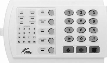
3 TABLE OF CONTENTS Code Pad Diagrams...2 Glossary of Terms...4 Understanding the Code Pad Lights...5 Code Pad Control Tones...6 Fully arming the system On Mode...7 Fully arming the system Quick Arm Mode...7 Partially arming the system Partial Mode...8 Disarming from the On or Partial Mode...8 Bypassing Individual Zones...9 Group Bypass...10 Changing & Adding User Codes...11 Deleting User Code...12 Walk Test...12 User Code Authorisation...13 Setting the Door Chime...13 Exit Mode Extend Exit Timer...14 Code Pad Emergency Keys...14 Viewing Alarm Memory...14 Reset Latched Alarms...15 Setting System Date...15 Setting System Time...16 Set Code Pad Tones...16 Program Telephone Number...17 Viewing Telephone Numbers...18 Cancelling Alarm Calls...18 Deleting Telephone Numbers...19 Communicator, Battery & Siren Test...19 Service Light...20 Emergency Evacuation Plans...21 Zone List...Back Page Page 3
4 GLOSSARY OF TERMS Authority Level: The level of access an individual has when using an alarm panel. Central Station: Location where alarm data is sent during an alarm report. Chime Feature: An option that allows the code pad to sound a ding-dong whenever an entry/exit door is opened. Codes: Can be either User Codes (relating to a person) or Function Codes (a toggle switch to turn specific functions on/off). NOTE: A system may have either 99 four (4) digit codes or 66 six (6) digit codes, but not a mixture of the two. Dialer Delay: An option that allows a delay in reporting to the central station. Duress Code: An option that allows a special code to be sent to the central station that indicates the alarm system is being operated under duress. Forced Arming: An option that allows the system to be turned on (ARMED) with one or more zones open. A system that is ready to be force armed will flash the ready light. (Note: Those zones that are not ready will not create an alarm.) Function Code: A Function Code is either a four (4) or six (6) digit code that has been programmed by the installer to operate a device. Group Bypass: An option that allows the user to bypass multiple zones with a single operation. Master Code: A master PIN code that can arm & disarm the alarm system, and can add and delete user PIN codes. Partial Arm: A mode used to arm the perimeter and unused areas of an occupied premises. Perimeter: The outer edge of the protected area, typically the windows and doors fitted with alarm sensors. Quick Arm: An option that allows you to turn on (ARM) the security system by pressing either the [ON] or [PARTIAL] key on the code pad control (for ARMING only) as programmed by the installing company. Universal Arming (Uni Arm): When enabled, your alarm system can automatically determine whether to arm in the Full mode or in the pre-set Partial mode by looking to see if you exit your premises or stay inside after arming your system. NOTE: This feature can be used in conjunction with Quick Arm. User Code: A four (4) or six (6) digit entry used to arm or disarm the system. Page 4
5 UNDERSTANDING THE LIGHTS Armed Light The armed light is on when the system is armed. The armed light is off when it is disarmed. The armed light will flash when there has been an alarm during the previous arm cycle. Bypass Light The bypass light is on when any zone in this code pad s area is bypassed. The zone(s) that is bypassed will also be illuminated. If the bypass light is off, no zones are bypassed. Chime Light The chime light is on when the chime feature is on ; off otherwise. Exit Light The exit light is on during the exit delay. Please note that the light will flash during the last 10 seconds of the exit delay as a warning that the time is running out. (The user may want to restart the exit delay if the exit light is flashing in order to prevent an alarm. The user may then press the [Exit] key to restart the exit delay before the delay expires.) Fire Light A steady fire light means a fire zone has been faulted. A rapidly flashing fire light means that a fire zone is in a trouble condition. On Light The on light is on when the system is armed. The on light is off when it is disarmed. Partial Light The partial light is lit when the system is armed in the Partial Mode. All non bypassed zones will be delayed and follow the Partial delay time. When armed in Partial Mode, the Arm, On, and Bypass lights will also be lit. Power Light The power light is lit if the primary power is on. The power light will flash if the system detects a low battery condition. Ready Light The ready light is lit when the system is ready to arm and flashes if ready to force arm. The ready light is off when the system is not ready to arm because of a zone(s) being faulted. Zone Light The zone lights are off when everything is normal. A zone light will be lit if the zone has been bypassed. If a zone light is flashing, that zone is in alarm or has been faulted. If a zone light is flashing rapidly, it means that the zone is in a trouble condition. Trouble conditions are: Hardwire Zone Tamper; Wireless Zone Tamper, Sensor Low Battery and Sensor Loss of Supervision (A combination of Alarm/Fault and Tamper/Trouble will produce a rapid flashing light for a short period of time, followed by a slow flashing light.) Page 5
6 CODE PAD CONTROL TONES Beeps for all key presses Sounds a continuous tone during the entry delay time. Pulses when a day zone is violated while the system is disarmed. Pulses when a fire zone has a trouble condition. Beeps 3 times for trying to arm with the Ready light off, if Force Arming has not been selected. Beeps for 1 second or emits a ding-dong sound for the Chime feature. Beeps during an exit delay; beeps rapidly for the last 10 seconds of an exit delay; and beeps 1 second at the end of the exit delay. Pulses when the armed status changes and the AC power is off. Pulses when the armed status changes and any zone(s) is bypassed. Pulses when the armed status changes and a low battery is detected. Pulses when the armed status changes and a tamper condition is detected. Beeps to indicate telephone line cut, if selected. Pulses when one or more of the following conditions are detected: zone or box tamper, low battery, AC power fail, or expander trouble. Entering a valid code will silence the code pad sounder when it is pulsing. Please contact your installer if a trouble condition exists. Page 6
7 FULLY ARMING THE SYSTEM ON MODE ON is used when the user is away from the premise and wants the interior protected. To arm in the ON Mode: Close all protected doors and windows. Ready light will light when all protected zones and sensors are secure. NOTE: If any zones are bypassed, a sensor in that zone can be violated without affecting the ready light. The security system will not arm if the ready light is not on. If the power light is off, you have no AC power. Restore power if possible. If not, contact your installation company. Enter your 4 digit user code to arm the system. The armed and exit lights will illuminate. You may now leave the building via the designated exit path. Note: The exit light will flash rapidly for the last 10 seconds of the exit delay as a warning to the user that the exit time is about to expire. Example shows a User code of 1234 being used to set the system to the ON Mode. FULLY ARMING THE SYSTEM QUICK ARM MODE Quick Arm is used when the person arming the alarm system does not have a user code, is leaving the premises and wants the interior protected. To arm in the Quick Arm Mode: Close all protected doors and windows. Ready light will light when all protected zones and sensors are secure. NOTE: If any zones are bypassed, a sensor in that zone can be violated without affecting the ready light. The security system will not arm if the ready light is not on. If the power light is off, you have no AC power. Restore power if possible. If not, contact your installation company. The [ON] key to arm the system. The armed and exit lights will illuminate. You may now leave the building via the designated exit path. Note: The exit light will flash rapidly for the last 10 seconds of the exit delay as a warning to the user that the exit time is about to expire. Example shows ON key being used to set the system to the Quick Arm Mode. Page 7
8 PARTIALLY ARMING THE SYSTEM PARTIAL MODE Partial arming allows you to temporarily exclude some rooms from security arming. For example, you may wish to exclude bedrooms at night when they are in use. Partial mode is also used for protecting exterior doors and windows (the home perimeter) when the user is inside. Partial is used when the user is inside the premise and wants protection around the perimeter. Listed below are the steps to arm in the Partial mode: Close all protected doors and windows. Ready light will light when all protected zones and sensors are secure. NOTE: If any zones are bypassed, a sensor in that zone can be violated without affecting the ready light. The security system will not arm if the ready light is not on. If the power light is off, you have no AC power. Restore power if possible. If not, contact your installation company. Press the [PARTIAL] key. The bypass light will illuminate if any zone(s) is bypassed. The light(s) corresponding to the bypassed zone(s) will illuminate, alerting the user that a zone(s) may be unprotected and can be faulted without an alarm. PARTIAL Press the Partial key to partially arm your premises DISARMING FROM THE ON OR Partial MODE When you enter the protected area through one of the designated Entry/Exit doors, the code pad control will sound a solid continuous tone for the duration of the entry delay time, or until you enter a valid code. After entering a valid code the red armed light will go off and the tone will stop. The security system is now DISARMED. If a valid code is not entered before the end of the entry delay, an alarm will occur. (NOTE: If the red armed light is flashing during the entry delay, the alarm system has been activated in your absence. Leave the building immediately and call your alarm company and/or the police from a safe location.) Enter your user code to disarm the system from the On or Partial mode. Page 8
9 BYPASSING INDIVIDUAL ZONES Bypassing is used to temporarily exclude one or more zones that would normally be protected. For instance, a pet may need to be left in a part of the house that is usually protected. If you wish to bypass one or more zones, this must be done while the system is in the disarmed state. The following steps are used for bypassing zones. Once you have Bypassed the zone(s) you may Arm the system via the ON or PARTIAL Mode. When your security system is disarmed, any zones that has been temporarily isolated or bypassed will be reset, and will therefore be protected when the system is armed again. To manually unbypass zones, perform the bypassing procedure on a zone that is already bypassed. The corresponding light for that zone will go off when un-bypassed. BYPASS This example shows a user bypassing zones 4 and Press the [BYPASS] key. (The bypass light flashes.) 0 4 Tick box if User code required 0 BYPASS 5 2. Enter a 2-digit zone indicating the zone you wish to bypass. (Example: Press the [0][4] keys for zone 4, press [0][5] keys for zone 5.) The corresponding light for that zone will turn on when bypassed. 3. Press the [BYPASS] key again. NB: Pleased check with your security installation company to determine if a user code is required to bypass zones. If this feature has been enabled you will be required to enter a valid user code after step 1., and before step 2. Page 9
10 GROUP BYPASS By pressing the [BYPASS] key, followed by the [0][0] key, then the [BYPASS] key again, all zones that are designated as group bypass zones will be bypassed. Now you can arm your system in either the [ON] or [PARTIAL] mode. Once armed pressing the [BYPASS] key again will toggle the bypassed zones on and off. 1. Press the [BYPASS] key. (The bypass light flashes.) Tick box if User code required 2. Press [0][0] keys. The group bypass zone lights will turn on when bypassed. 3. Press the [BYPASS] key again. NB: Pleased check with your security installation company to determine if a user code is required to group bypass. If this feature has been enabled you will be required to enter a valid user code after step 1., and before step 2. Page 10
11 CHANGING & ADDING USER CODES On occasion you may need to change your arm & disarm codes, either as a security measure or for your own convenience. User Codes are 4 digits long and must all be different to each other. A master Code must be used to Change and Add user codes. The default master code is user code one [01] with a code of [1234]. Any user code can be assigned as a master code (See User Code Authorisation). Note the system must be disarmed before user codes can be changed or added. 1. Press [*] [5]. 2. Enter an existing master code. 3. Enter the user code to add or change. (e.g. user code 01) 4. Enter the new four-digit user code. 5. Repeat steps 3 and 4 for additional user codes. 5. Press [#] when completed. Page 11
12 DELETING A USER CODE You may be required to delete a user code, for example, when a member of the household leaves home, or the home is purchased from another family. * CHIME CHIME CHIME 3 CHIME 4 1. Press [*] [5]. 2. Enter an existing master code. 3. Enter the user code to be deleted (e.g. user code 03) 4. Press the [Chime] key four (4) times to delete the user code. # 5. Repeat steps 3 and 4 for additional user codes. 6. Press [#] when completed. WALK TEST Walk test is used to test the functionality and should be performed regularly. When in walk test mode the code pad transmits the chime sound each time a zone is activated, and will light the activated zone number in the code pad for the duration of the walk test period. You must exit the walk test mode when you have completed testing or are satisfied the zones function correctly. Note: the alarm system will not report to the control room during the walk test. 1. Press [*] [CHIME]. 2. Enter a master code. The system is now in walk test mode. 3. Walk past each motion sensor and return to the code pad to check each zone light to validate the sensors are working correctly. 4. Enter a master code to exit walk test. If no master code is entered, walk test mode will automatically exit in 15 minutes. Page 12
13 USER CODE AUTHORISATION Any user code can be assigned the master code status to allow that user to change or add other codes and provide access to other system functions. Example shows enabling user two [02] as a master code. 1. Press [*] [6]. * # # 2. Enter an existing master code. 3. Enter the user code to have changed to a master code. (e.g. User code 02) 4. Press [4] key. LED 4 will light up to indicate the user is now a master code. If LED 4 is not lit then it is a normal user code. 5. Repeat steps 3 and 4 for additional user codes. 6. Enter [*] 7. Enter [#][#] when completed. SETTING THE DOOR CHIME Chime Mode provides only an audio warning at the premises. A ding-dong is sounded from the code pad when the protected area is entered, for example, when an infant opens the door. The door chime is turned on or off by pressing the [CHIME] key while the system is in the disarmed state. If the chime is on, the chime light will be lit. If the chime is off, the chime light will be off. Each press of the [CHIME] key will toggle the chime feature on/off. Chime mode must be programmed by your security Installation Company. Tell the installer if Chime mode is required for any areas. Press the [CHIME] key to turn on or turn off the chime feature. Page 13
14 EXIT MODE EXTEND EXIT TIMER Exit mode is used when you have already armed your Security System, but need to extend your exit time. Pressing the exit button will re-start your exit time, but you may only press Exit button twice. The code pad will beep faster in the last ten (10) seconds as a warning. EXIT Press [Exit] key to extend the exit time. Code Pad Emergency Keys Three (3) emergency features are available to be programmed into your code pad to provide support in the areas of personal safety: Medical, Police (duress) and Fire arm. You must hold these keys for two (2) seconds to activate these functions. You should press these keys only in an emergency situation that requires response by emergency personnel. Check with your security installation company to find out if your system is programmed for these activation keys. Press this key and hold for two (2) seconds to activate the fire alarm. VIEWING ALARM MEMORY Press this key and hold for two (2) seconds to activate the medical/auxiliary alarm. Press this key and hold for two (2) seconds to activate the police/duress (panic/hold-up) alarm. Whenever an alarm activation occurs on your system all zones that were in alarm during that activation will be held in memory. The last alarm activation can be reviewed via the function listed below. I.e. You can see which area has activated the alarm. The alarm memory feature will flash those zone/s that created alarms and will light steady the zones that were bypassed during the last alarm. Page 14
15 RESET LATCHED ALARMS Reset Latched Alarms function resets smoke detectors, zone troubles and zone tampers alarms. Note: If the code pad begins beeping, the reset did not execute properly. Enter your code to silence the code pad. Wait a few minutes and repeat the reset function to attempt another reset. If the code pad still beeps after repeated attempts, please contact your installer. 1. Enter you code to silence the code pad sounder. 2. Press [*] [7] to activate the reset function. SETTING SYSTEM DATE * Example shows setting date as Monday, June 11, Press [*] [9] [6] keys. 2. Enter the master code. 3. Enter the day of the week (1=Sunday, 7=Saturday). 4. Enter the month code. Must be two (2) digits. E.g. [0][6] for June # 5. Enter the day code. Must be two (2) digits. E.g. [1][1] for the 11 th day. 6. Enter the last two (2) digits of the year code. E.g. [0][7] for Press [#] to exit. Your date is now set. Page 15
16 SETTING SYSTEM TIME * # Example shows setting time at 9.30am. 1. Press [*] [9][7] keys. 2. Enter the master code. 3. Enter the hour code. Must be two (2) digits. E.g. [0][9] for 9am. 4. Enter the minutes code. Must be two (2) digits. E.g. [3][0] for 30 minutes. 5. Press [#] to exit. Your time is now set. SET CODE PAD TONES Each code pad can have its sounder tone frequency adjusted to your individual requirements. Follow the steps bellow to adjust the code pad sounder. 1. Enter [*] [0] to start the code pad tone adjustment. The code pad sounder will sound at the current set frequency. 2. Enter the one [1] key to raise the tone or the two [2] key to lower the tone. 3. Enter [#] to exit and save the selected code pad tone. Page 16
17 PROGRAM PHONE NUMBERS * You may have a requirement where, in the instance of alarm activation, you want the panel to dial a particular phone number. E.G. Your mobile phone. There are three (3) numbers that can be viewed, entered/changed or deleted. Only numbers set to pager or siren tone telephone formats can be modified by you. One of these formats must have been programmed by the alarm panel installer for you to access this feature. Contact your security installation company to ask if the pager or siren tone format was programmed for your use. When confirmed use the following: Phone number 1 is [*][4][1] Phone number 2 is [*][4][2] Phone number 3 is [*][4][3] To program a new phone number you must do the following 4 2 Example shows programming phone number Press [*] and [4] [2] for phone number # 2. Enter the master code. 3. Enter the phone number, not exceeding twenty (20) digits. (Use the table below to determine the key values). 4. Press [#] to end and exit. Key Phone Digit Key Phone Digit [1] 1 [On] Star (*) [2] 2 [Partial] Hash (#) [3] 3 [Exit] 4 Sec delay [4] 4 [Bypass] Disable [5] 5 [Chime] Pulse Dialling [6] 6 [7] 7 [8] 8 [9] 9 [0] 0 Page 17
18 VIEWING TELEPHONE NUMBERS You may wish to check the phone numbers that have been programmed for your security system. * * # Example shows viewing phone number Press [*] and [4] [1] for phone number Enter the master code. You are now in the view mode, and the first phone digit will be displayed. (Use the following table to read the code pad lights). 3. Press the [*] key to move to the next digit(s). 4. Press [#] to end and exit. Zone Light Phone Digit Light Phone Digit Zone 1 1 [Fire] 9 Zone 2 2 [Service] 0 Zone 3 3 [On] Star (*) Zone 4 4 [Partial] Hash (#) Zone 5 5 [Exit] 4 Sec Delay Zone 6 6 [Bypass] Disable Zone 7 7 [Chime] Pulse Dialling Zone 8 8 Zone 9 9 Zone 10 0 Cancelling Alarm Calls Note: Alarm calls will be heard as siren tone pause - siren tone, this will repeat several times. You can stop the alarm system calling you, or any further programmed numbers, by pressing the star key for 2 seconds during the pause period of the call. This will also end the current call. Page 18
19 DELETING TELEPHONE NUMBERS You may need to delete a phone number you have previously chosen. For example, if you cancelled a mobile phone account. * BYPASS # Example shows deleting phone number Press [*] and [4] [3] for phone number Enter the master code. 3. Press the [Bypass] key to delete the saved number. 4. Press [#] to end and exit. COMMUNICATOR, BATTERY & SIREN TEST This test will only be performed if the installer has programmed this option on. The test conducts a communicator test (once), a battery test and siren test. The communicator, battery and sirens should be tested regularly. Contact your security installation company to find out if this test is available. 1. Enter keys [*] [4] [4] to initiate the test. Note: Sirens will sound during this test. 2. Enter a user code to end the test. Page 19
20 SERVICE LIGHT The service light will be lit if the security system requires service. If the service light is lit, press the [*] key followed by the [2] key to determine the service condition. One or more zone lights will illuminate indicating what service(s) is required. Call your local security installation company immediately for these problems. Below is a listing of what each light means in a service condition. 1. Enter keys [*] [2] and use the table below to identify the service condition. LIGHT 1 Condition SYSTEM FAULT - Press the [1] key. The zone light(s) that is illuminated corresponds to the system fault(s) below: 1 Over Current Fault 5 Expander Low Battery 2 Siren Trouble 6 Expander Box Tamper 3 Box Tamper 7 Expander Trouble 4 Expander Power 8 Reserved Note: Faults 1 & 2 are global in nature and will affect all areas of a multi-area system. Press the [#] key to return to the 1 of 8 service lights. 2 ZONE TAMPER - Press the [2] key and the zone light(s) will illuminate showing the zone(s) that is tampered. Press the [#] key to return to the 1 of 8 service lights. 3 ZONE LOW BATTERY - Press the [3] key. The zone light(s) will illuminate showing which zone(s) has a low battery. This only applies to wireless zones. Press the [#] key to return to the 1 of 8 service lights. 4 ZONE LOSS OF SUPERVISION - Press the [4] key and the zone light(s) will illuminate showing which zone(s) has loss of supervision. This only applies to wireless zones. Press [#] key to return to the 1 of 8 service lights. 5 ZONE TROUBLE - Press the [5] key and the zone light(s) will illuminate showing which zone(s) has a trouble condition. Press the [#] key to return to the 1 of 8 service lights. 6 TELEPHONE LINE TROUBLE/LINE CUT - There is telephone line trouble or the telephone line has been cut. The service light will remain lit until the telephone trouble clears and a user code is entered. Note: This fault is global in nature and will affect all areas of a multi-area system. 7 FAILURE TO COMMUNICATE There is a failure to communicate between your system and the central station. Note: This fault is global in nature and will affect all areas of a multi-area system. 8 LOSS OF SYSTEM TIME - There has been a loss of power and your system clock needs to be reset. Instructions are on page 15. Note: This fault is global in nature and will affect all areas of a multi-area system. Exit To exit the Service Light Mode - press the [#] key. Page 20
21 EMERGENCY EVACUATION PLANS An emergency evacuation plan should be established for an actual fire alarm condition. For example, the following steps are recommended by the National Fire Protection Association and can be used as a guide in establishing an evacuation plan for your building. Draw up a floor plan of your home. Show windows, doors, stairs, and rooftops that can be used for escape. Indicate each occupant's escape routes. Always keep these routes free from obstruction. Determine two means of escape from each room. One will be the normal exit from the building. The other may be a window that opens easily. An escape ladder may have to be located near the window if there is a long drop to the ground below. Set a meeting place outdoors for a headcount of the building occupants. Practice escape procedures. In a home, sleep with bedroom door closed; this will increase your escape time. If you suspect fire, test the door for heat. If you think it is safe, brace your shoulder against the door and open it cautiously. Be ready to slam the door if smoke or heat rush in. Practice escaping to the outdoors and meeting in an assigned spot. Call the Fire Department from a neighbour s phone. NOTE: After the installation of your Security System has been completed, notify your local Fire and Police Departments to give them your name and address for their records. Early warning fire detection is best achieved by the installation of fire detection equipment in all rooms. also have other rights which vary from State to State. Page 21
22 Page 22
23 WARNING NOTICES This product is to be installed by qualified SERVICE PERSONNEL only The equipment should only be operated with an approved power adapter with insulated live pins. CAUTION RISK OF EXPLOSION IF BATTERY IS REPLACED BY AN INCORRECT TYPE. DISPOSE OF BATTERIES ACCORDING TO THE INSTRUCTIONS. CONTACT YOUR INSTALLER FOR REPLACEMENT BATTERIES When installed as directed, this product conforms to the standards set by Standards Australia on behalf of the Australian Communications Authority (ACA). Hills LED Keypad User Manual
24 Programmed Phone Number 1: Programmed Phone Number 2: Programmed Phone Number 3: 1 ZONE LIST ENTRY / EXIT 24 STAY MODE 24 HOUR For Service Contact
Understanding the Code Pad lights...4. Code Pad tones...5. Fully arming the system On MODE...6. Fully arming the system - Quick Arm MODE...
 TABLE OF CONTENTS...Glossary of terms...2...code Pad Diagram...3 Understanding the Code Pad lights...4 Code Pad tones...5 Fully arming the system On MODE...6 Fully arming the system - Quick Arm MODE...6
SECURITY SYSTEM NOTES
 SECURITY SYSTEM NOTES Installing/Service Company For Service Call Central Station Duress Code FUNCTION CODES Function Code Controls Function EMERGENCY ACTIVATION KEYS (check if enabled) Fire Auxiliary
NetworX NX-8V2. LED Keypad User Manual
 NetworX NX-8V2 LED Keypad User Manual POWER Light is on when AC power is present; flashes to indicate a low battery condition. ARMED Light is on when armed; off when disarmed; flashes to indicate a previous
NETWORX TM. User manual NX-4
 NETWORX TM User manual NX-4 POWER Light is on when AC power is present; flashes to indicate a low battery condition. ARMED Light is on when armed; off when disarmed; flashes to indicate a previous alarm.
ABORT Light flashes during an abort delay time; is on during or after an alarm report to the central station. EMERGENCY ACTIVATION KEYS
 POWER Light is on when AC power is present; flashes to indicate a low battery condition. CHIME Light is on when the chime feature is active. ABORT Light flashes during an abort delay time; is on during
NetworX Series NX-1500E LED Keypad
 NetworX Series NX-1500E LED Keypad User Manual SECURITY SYSTEM NOTES Installing/Service Company For Service Call Central Station Duress Code FUNCTION CODES Function Code Controls Function This system
NX-148 LCD CODE PAD TABLE OF CONTENTS
 NX-148 LCD CODE PAD TABLE OF CONTENTS Glossary Of Terms... 4 Understanding The Lights... 5 Code Pad Functions Arming In The ON Mode... 6 Making The System Ready To Arm... 7 Using Quick Arm... 7 Arming
SECURITY SYSTEM NOTES SPECIAL CODES ENTRY / EXIT DELAY TIMES ARM / DISARM CODES ZONE DESCRIPTIONS
 SECURITY SYSTEM NOTES Installing/Service Company For Service Call SPECIAL CODES "Chime" Digit 1 "Partial Arm" Digit 2 "Quick Arm" Digit 3 ENTRY / EXIT DELAY TIMES Exit Delay Time Entry Delay Time Secondary
SPECIAL CODES AUXILIARY CODES SYSTEM NOTES
 Installing/Service Company For Service Call SPECIAL CODES Master Code Duress Code AUXILIARY CODES "Quick Arm" " Chime" 08 02 09 03 10 04 11 05 12 06 13 07 14 SYSTEM NOTES Exit Delay Time Entry Delay Time
SPECIAL CODES AUXILIARY CODES SYSTEM NOTES
 Installing / Service Company Monitoring Station SPECIAL CODES Master Code Duress Code AUXILIARY CODES "Quick Arm" "Chime" 08 02 09 03 10 04 11 05 12 06 13 07 14 SYSTEM NOTES Exit Delay Time Entry Delay
HILLS Series LCD Code Pad User Manual
 HILLS Series LCD Code Pad User Manual THIS MANUAL IS FURNISHED TO HELP YOU UNDERSTAND YOUR SECURITY SYSTEM AND BECOME PROFICIENT IN ITS OPERATION. ALL USERS OF YOUR SECURITY SYSTEM SHOULD READ AND FOLLOW
Contents. Glossary Introduction to the IDS Notes Understanding the Keypad Indicators Operation of the Keypad...
 2 Contents Glossary...7 1. Introduction to the IDS805...8 1.1 Notes...8 2. Understanding the Keypad Indicators...8 3. Operation of the Keypad...9 4. System Information...10 4.1 Programmed Functions...10
IDS800 USER MANUAL. Summary of Operation. + [ ] 2 IDS800 USER MANUAL NO K ISSUED APR 2003 VER 1.44
![IDS800 USER MANUAL. Summary of Operation. + [ ] 2 IDS800 USER MANUAL NO K ISSUED APR 2003 VER 1.44](/thumbs/89/98095999.jpg "IDS800 USER MANUAL. Summary of Operation. + [ ] 2 IDS800 USER MANUAL NO K ISSUED APR 2003 VER 1.44") Summary of Operation A rm/ disarm [#] + [USER CODE] Quick Quick Quick Away Arm Stay Arm Stay Arm & Go H old down [ 1] for 1 second H old down [ 5] for 1 second H old down [ 6] for 1 second Panic Fire Medical
Summary of Operation A rm/ disarm [#] + [USER CODE] Quick Quick Quick Away Arm Stay Arm Stay Arm & Go H old down [ 1] for 1 second H old down [ 5] for 1 second H old down [ 6] for 1 second Panic Fire Medical
NX148-E LCD KEYPAD TABLE OF CONTENTS
 NX148-E LCD KEYPAD TABLE OF CONTENTS GLOSSARY OF TERMS... 3 UNDERSTANDING THE LIGHTS... 4 KEYPAD FUNCTIONS... 5 ARMING YOUR SYSTEM IN THE AWAY MODE... 5 MAKING YOUR SYSTEM READY TO ARM... 5 ARMING YOUR
User s Guide. SUB-MA7240O-0001.OG.Solution doc. Created: 6/05/03. Last Updated: 23/09/03. MA7240AO-0001 Version 1.0
 User s Guide SUB-MA7240O-0001.OG.Solution40-111.doc Created: 6/05/03 Last Updated: 23/09/03 MA7240AO-0001 Version 1.0 2 Table Of Contents User List...6 Quick Reference..7 Features...7 Keypad User's Guide...8
Tomorrow s technology for today s security needs.
 Tomorrow s technology for today s security needs. The Security Command Keypad Welcome Congratulations on your decision to purchase a Security Command system. The new Security Command keypad, from one of
Contents. Glossary
 Contents Glossary ------------------------------------------------------------------------------------------------------ 6 1. Introduction to the IDS 1632 -------------------------------------------------------------
Control/Communicator Installation Manual
 DAS NETWORX NX-12 Control/Communicator Installation Manual General Description...2 Ordering Information...2 Option Definitions...3 Programming the LED Code Pads...5 Programming the NX-12...9 Types of Programming
L900 series USER MANUAL
 INTRODUCTION The BLUGUARD Control Panel is designed for simple operation yet provides the maximum protection for you. Please read this manual carefully and follow the instructions contained in this book.
Condominium Security Management System
 User Access Codes The CONDOPLEX series panels can be programmed with nine (9) different user codes and one (1) duress code. User codes are normally used for arming and disarming the panel. The duress code
Security System. User s Guide for the Text Command Center
 User s Guide for the Text Command Center MY ALARM COMPANY IS: CALL BEFORE TEST: THIS SECURITY SYSTEM IS CONNECTED TO TELEPHONE NUMBER: THE SECURITY CONTROL PANEL IS CONNECTED TO THE PHONE JACK LOCATED:
IDS S E C U R I T Y IDS816. User Manual MANUAL NO B ISSUED DEC 2004 VERSION 2.00
 INHEP DIGITAL IDS S E C U R I T Y IDS816 User Manual MANUAL NO. 700-283-01 B ISSUED DEC 2004 VERSION 2.00 Contents 1. Introduction to the IDS816... 4 2. Understanding the Keypad Indicators... 4 3. Programmable
636 and 646 Keypads. User s Manual
 636 and 646 Keypads 636 646 User s Manual Table Of Contents Basic Operation... 2 Access Codes... 4 Arming & Disarming... 5 Panic Zones... 11 Key Access Programming... 12 Additional Features... 13 Trouble
Security System. User Guide for the LED Command Center
 Security System User Guide for the LED Command Center National Security Systems Inc (800)457-1999 MY SECURITY COMPANY IS: CALL BEFORE TEST: THIS SECURITY SYSTEM IS CONNECTED TO TELEPHONE NUMBER: THE SECURITY
Watchguard WGAP864 User Manual
 Watchguard WGAP864 User Manual v1.0 Issued September 2016 1 2 Table of Contents Glossary... 5 1. Introduction to your Watchguard WGAP864... 6 2. Before Operating your Alarm System... 6 3. Understanding
IDS816 User Manual H Issued January 2009
 1 Contents Glossary-------------------------------------------------------------------------------------------------------------------6 1. Introduction to the IDS 816---------------------------------------------------------------------------7
D1265. User's Guide. Touchscreen Keypad
 D1265 EN User's Guide Touchscreen Keypad D1265 User's Guide Contents This system includes a telephone line seizure feature. The system can be programmed to communicate with a central monitoring station
AXI LED USER MANUAL (REV. 1.0)
") Security & Home Automation System AXI LED USER MANUAL (REV. 1.0) CONTENTS PREFACE FEATURES LED KEYPAD OUTLOOK 1.0 LIGHT INDICATION 1 2 4 6 CHAPTER 1: ALARM SYSTEM CONTROL 1.0 USING LED KEYPAD 1.0.1 ARMING
Security & Home Automation System AXI LED USER MANUAL (REV. 1.0) CONTENTS PREFACE FEATURES LED KEYPAD OUTLOOK 1.0 LIGHT INDICATION 1 2 4 6 CHAPTER 1: ALARM SYSTEM CONTROL 1.0 USING LED KEYPAD 1.0.1 ARMING
PROGRAMMING PROCEDURES (Table 3)
") CONDOPLEX 2600/2600A/2700 Suite Panel User Manual Document Version 8.4 Oct 19, 1998 Condoplex 1998 PROGRAMMING PROCEDURES (Table 3) FUNCTION PRESS KEYPAD DISPLAY Delete user code or duress code. 0 (hold)
CONDOPLEX 2600/2600A/2700 Suite Panel User Manual Document Version 8.4 Oct 19, 1998 Condoplex 1998 PROGRAMMING PROCEDURES (Table 3) FUNCTION PRESS KEYPAD DISPLAY Delete user code or duress code. 0 (hold)
User s Information Guide R2A
 Pi HSC505 Home Security Controller User s Information Guide R2A Page 1 of 15 of its development program. 1This document and product are copyrighted and all rights are reserved. Introduction Convention
Table of Contents About This User s Guide... 2 Introduction... 2 Security System Basics... 3 What is a Point?... 3 What is a Faulted Point?...
 Table of Contents About This User s Guide... 2 Introduction... 2 Security System Basics... 3 What is a Point?... 3 What is a Faulted Point?... 3 Are All Points the Same?... 3 Controlled Points... 4 24-Hour
Alarm Control Panel WIC-16Z4P WIC-5Z2P. User Instructions
 WIC-16Z4P WIC-5Z2P User Instructions Page : 2/14 INDEX # Function Page 1 Add a New User Code 11 2 Arm or Disarm All Areas or Disarm Selected Areas (Partitioned System) 8 3 Arming the System (Away Mode)
DS7446KP. User Guide. Keypad
 DS7446KP EN User Guide Keypad DS7446KP User Guide Command Quick Reference Command Quick Reference Command Type Basic Arming Commands Advanced Arming Commands System Disarming Commands Command Turn the
IDS S E C U R I T Y IDS816. User Manual MANUAL NO C ISSUED APRIL 2005 VERSION 2.00
 INHEP DIGITAL IDS S E C U R I T Y IDS816 User Manual MANUAL NO. 700-283-01C ISSUED APRIL 2005 VERSION 2.00 Contents 1. Introduction to the IDS816... 4 2. Understanding the Keypad Indicators... 4 3. Programmable
Using Your. Security System With LED Keypad S5030, S5031, S5032
 Using Your Security System With LED Keypad S5030, S5031, S5032 Contents 1 Overview Your Security System... 1 How Your Security System Works... 2 Your System's Programming... 3 Getting Used to Your System...
IDS S E C U R I T Y IDS816. User Manual. MANUAL NO A ISSUED November 2004 VERSION 1.00
 INHEP DIGITAL IDS S E C U R I T Y IDS816 User Manual MANUAL NO. 700-283-02A ISSUED November 2004 VERSION 1.00 Contents 1. Introduction to the IDS816... 4 2. Understanding the Keypad Indicators... 4 3.
Master Code Arming Auto-Bypass Option - Home-Away Arming Entry Delay Off Arming
 Master Code The 4 digit Master Code is used for arming and disarming the system, for programming additional access codes, and for changing other features. The Master Code will be supplied to you by your
Destiny Destiny Owners Manual
 Destiny 4100 Destiny 4100 Owners Manual TABLE OF CONTENTS INTRODUCTION Control Panel...3 Detection Devices...3 Telephone Keypads...3 GLOSSARY... 4-5 LOCAL PHONE ACCESS Using Your Telephones As Keypads...6
0 4 / 0 4 / 1 4. GE Concord 4 Quick User Guide. GE Concord 4 Quick User Guide Page 1
 0 4 / 0 4 / 1 4 GE Concord 4 Quick User Guide GE Concord 4 Quick User Guide Page 1 Before Calling Is the keypad beeping? Press *. This will silence the beeping and let you know where the trouble is. Is
DESTINY 6100 SERIES SECURITY SYSTEM OWNER S MANUAL V1 12/01
 DESTINY 6100 SERIES SECURITY SYSTEM OWNER S MANUAL 800-6006V1 12/01 System Overview General Information Control Panel Detection Devices You have made a wise decision to protect your family and property
Version 1.03 January-2002 USER S MANUAL
 Version 1.03 January-2002 1 USER S MANUAL 2 Version 1.03 January-2002 System Details CUSTOMER:...... PHONE:... FAX:... INSTALLED BY:...... PHONE:... FAX:... MAINTENANCE & SERVICE:...... PHONE:... FAX:...
Intruder alarm system Operating Instructions
 Intruder alarm system Operating Instructions 0 2 3 4 5 6 7 8 9 CHIME OMIT RESET PROG SET S Power 0 2 3 5 6 7 8 Chime Omit Prog 4 9 Set AccentaG3 mini Servicing organisation details Servicing organisation
Safewatch Pro 3000 System Manual
 «Help Center Select System System Arm & Panic Alarms Trouble User Access System Other System Overview Keywords Disarm the Conditions Codes Testing Information System System Overview Overview The Safewatch
LED Keypads D720 Series User s Guide
 LED Keypads D720 Series User s Guide D720 D720W D720B Table of Contents Fire Safety 3 The D720/D720W/D720B Keypad 4 Security System Basics 5 Turning the System On and Off 7 Silencing and Reporting Alarms
Digiplex LED Keypads User s Manual
 KLEDEU03.fm Page -1 Friday, May 4, 2001 11:25 AM Digiplex LED Keypads User s Manual KLEDEU03.fm Page 0 Friday, May 4, 2001 11:25 AM KLEDEU03.fm Page 1 Friday, May 4, 2001 11:25 AM TABLE OF CONTENTS 1.0
Solution Ultima Series Operators Manual ISSUE 1.00
 Solution Ultima Series Operators Manual ISSUE 1.00 Solution Ultima Series Operators Manual Copyright 1998 by, SYDNEY, AUSTRALIA Document Part Number MA488O DOCUMENT ISSUE 1.00 Printed 16 February 1999
Installation Manual Premier 412/816/832. Issue 10
 Installation Manual Premier // Issue 0 Premier // Installation Manual 5. Operating the System Introduction Before attempting to operate the alarm system ensure you have familiarised yourself with all the
&RPPHUFLDO%XUJODU\ 3DUWLWLRQHG6HFXULW\6\VWHP ZLWK6FKHGXOLQJ
 READY ARMED READY 1 OFF 7 INSTANT READY 2 AWAY 8 CODE 6BYPASS 9 CHIME 9,67$% &RPPHUFLDO%XUJODU\ 3DUWLWLRQHG6HFXULW\6\VWHP ZLWK6FKHGXOLQJ 8VHU*XLGH ARMED READY 1 OFF 2 AWAY 3 STAY 4 MAX 5 TEST 6 BYPASS
Total Connect Box. User manual
 Total Connect Box User manual 1 Congratulations on your purchase of the Honeywell Total Connect Box security system. To make the best out of your system we advise you to read this manual carefully. This
TS400 & TS410. Intruder Alarm Control Panels. Operating Instructions
 TS400 & TS410 Intruder Alarm Control Panels Operating Instructions Zone Location Home Set Chime 1 Armed / Omitted 2 Armed / Omitted 3 Armed / Omitted 4 Armed / Omitted 5 Armed / Omitted F. Exit Always
CC880/LP880, SC8016. Operators Guide Solution-16, Solution-16 Safecom
 CC880/LP880, SC8016 EN Operators Guide Solution-16, Solution-16 Safecom CC880/LP880, SC8016 Operators Guide EN 2 Copyright Notice Unless otherwise indicated, this publication is the copyright of Bosch
ICP-CC488 ICP-CC488 EN. Control Panel. User s Guide
 ICP-CC488 EN User s Guide ICP-CC488 Control Panel ICP-CC488 User's Guide Notices EN 2 Copyright Notice Unless otherwise indicated, this publication is the copyright of Bosch Security Systems, Inc. ( Bosch
Power864. User s Guide. Now classified in accordance with ANSI/SIA CP (SIA-FAR)
") WARNING This manual contains information on limitations regarding product use and function and information on the limitations as to liability of the manufacturer. The entire manual should be carefully
WARNING This manual contains information on limitations regarding product use and function and information on the limitations as to liability of the manufacturer. The entire manual should be carefully
DESTINY OWNER S MANUAL
 DESTINY OWNER S MANUAL DESTINY You have made a wise decision to protect your family and property with the DESTINY Security System. The DESTINY has been designed to provide you with a maximum level of security
Area Systems While the alarm bell or siren is sounding, enter your user code. The system silences the alarm bell or siren.
 XR20 User s Guide Silencing an Alarm All/Perimeter and Home/Away Systems While the alarm bell or siren is sounding, enter your user code. The keypad displays DISARM SILENCE. Press the Select key under
&RPPHUFLDO)LUHDQG%XUJODU\ 3DUWLWLRQHG6HFXULW\6\VWHP ZLWK6FKHGXOLQJ
LUHDQG%XUJODU\ 3DUWLWLRQHG6HFXULW\6\VWHP ZLWK6FKHGXOLQJ") 9,67$)% &RPPHUFLDO)LUHDQG%XUJODU\ 3DUWLWLRQHG6HFXULW\6\VWHP ZLWK6FKHGXOLQJ 8VHU*XLGH FIRE FIRE * PULL K3522 3/99 TABLE OF CONTENTS SYSTEM OVERVIEW...4 General...4 A Partitioned System...4 Zones...5 Fire
9,67$)% &RPPHUFLDO)LUHDQG%XUJODU\ 3DUWLWLRQHG6HFXULW\6\VWHP ZLWK6FKHGXOLQJ 8VHU*XLGH FIRE FIRE * PULL K3522 3/99 TABLE OF CONTENTS SYSTEM OVERVIEW...4 General...4 A Partitioned System...4 Zones...5 Fire
XRSuper6. User s Guide
 XRSuper6 User s Guide Silencing an Alarm All/Perimeter and Home/Away Systems While the alarm bell or siren is sounding, enter your user code. DISARM SILENCE. Select SILENCE to stop the bell or siren. This
NX-1192E LCD Keypad. User s Manual
 NX-1192E LCD Keypad User s Manual READY Light is on when the system is ready to arm. Flashes if ready to force arm. ARMED Light is on when armed, off when disarmed. Flashes to indicate a previous alarm.
Solution Ultima 862 Operators Manual ISSUE 1.10
 Solution Ultima 862 Operators Manual ISSUE 1.10 Solution Ultima 862 Operators Manual Copyright 2001 by, SYDNEY, AUSTRALIA Document Part Number MA486O DOCUMENT ISSUE 1.10 Printed 24 April 2001 This documentation
$'(0&2 9,67$ 3DUWLWLRQHG 6HFXULW\ 6\VWHP 8VHU *XLGH N7003V3 5/04 Rev A
 $'(0&29,67$ 3DUWLWLRQHG6HFXULW\6\VWHP 8VHU*XLGH N7003V3 5/04 Rev A 2 TABLE OF CONTENTS SYSTEM OVERVIEW...5 General...5 A Partitioned System...5 Zones...5 Fire Protection...6 Burglary Protection...6 Alarms...6
USER'S GUIDE FA1220CV. 2-Partition Security System N7003-1V2 7/98
 USER'S GUIDE FA1220CV 2-Partition Security System N7003-1V2 7/98 SYSTEM OVERVIEW... 3 General... 3 A Partitioned System... 3 Zones... 3 Burglary Protection... 4 Fire Protection... 4 Alarms... 5 Emergency
**** **** A B ARMED FIRE FIRE C D READY OFF AWAY STAY 2 3 MAXIMUM TEST BYPASS PULL INSTANT CODE CHIME. First Alert READY. * 0 # Professional
 ARMED READY READY )$&&$&% )LUHDQG%XUJODU\ 3DUWLWLRQHG6HFXULW\6\VWHPV ZLWK6FKHGXOLQJ **** **** A B C D FIRE FIRE First Alert OFF AWAY STAY 2 3 1 4 5 6 7 8 9 MAXIMUM TEST BYPASS INSTANT CODE CHIME * 0 #
Wireless Keypad GKP-S8M
 Wireless Keypad GKP-S8M User manual Contents Congratulations on your purchase of this Honeywell wireless keypad. To make the best out of your equipment we advise you to read this manual carefully. This
Table of Contents. Appendix A Special Characters 31
 Table of Contents Introduction 2 Section 1: General System Operation 3 1.1 Getting to Know Your System... 3 1.2 How to Arm... 4 1.3 Alternate Arming Methods... 5 1.4 Disarming... 6 1.5 Alarm Memory...
Wireless Keypads LKP(E)S8M Series
S8M Series") Wireless Keypads LKP(E)S8M Series User manual Contents Congratulations on your purchase of this Honeywell wireless keypad. To make the best out of your equipment we advise you to read this manual carefully.
Wireless Keypads LKP(E)S8M Series User manual Contents Congratulations on your purchase of this Honeywell wireless keypad. To make the best out of your equipment we advise you to read this manual carefully.
Power Wave LCD Keypads. Users Operating and Programming Guide Version 2.00
 Power Wave LCD Keypads CR-16S CR-16M Users Operating and Programming Guide Version 2.00 P/N 7102265 Rev. C N.A May 2003 Contents Introduction...4 Meet the PowerWave Alarm Control System... 4 Typical Alarm
Table of Contents. Page Code
 Table of Contents Introduction Command Center Function Keys Security System Basics Your Custom Display View Faulted or Bypassed Points Warning Displays and Tones Fire Alarms Burglary Alarms Fire Trouble
 Solution-6 Operators Manual Page 1 Preface Congratulations on selecting the Solution-6 security control system for your installation. So that you can obtain the most from your unit, we suggest that you
Accenta/Optima. User Guide. UK Security Panels. Servicing Organisation (Installer) name: Telephone Number: Date of Installation: Account Number:
 name: Telephone Number: Date of Installation: Account Number:") Accenta/Optima User Guide ZONE 1 2 3 4 5 6 7 8 9 Chime Omit Prog PA 0 1 2 3 4 5 6 7 8 9 CHIME OMIT RESET PROG SET Accenta + TA PA DAY POWER PA! " # $ % & 0 1 2 3 5 6 7 8 Chime Omit Reset Prog 4 9 Set PA
Accenta/Optima User Guide ZONE 1 2 3 4 5 6 7 8 9 Chime Omit Prog PA 0 1 2 3 4 5 6 7 8 9 CHIME OMIT RESET PROG SET Accenta + TA PA DAY POWER PA! " # $ % & 0 1 2 3 5 6 7 8 Chime Omit Reset Prog 4 9 Set PA
VISTA-20PMT. Security. Systems. User s Guide. Monitronics
 VISTA-15PMT VISTA-20PMT Security Systems User s Guide Monitronics R I N T E R N A T I O N A L, I N C. K5309-1MTV2 7/04 Rev. A Reference: MTV15P, MTV20P IMPORTANT! PROPER INTRUSION PROTECTION For proper
VISTA-50P VISTA-50PUL
 Security System User's Manual VISTA-50P VISTA-50PUL N5943-6V1 Rev B 4/99 TABLE OF CONTENTS SYSTEM OVERVIEW...4 General...4 A Partitioned System...4 Zones...4 Fire Protection...5 Burglary Protection...5
INSTRUCTION MANUAL PC255O
 INSTRUCTION MANUAL PC255O Canadian Department of Communications Notice NOTICE: The Canadian Department of Communications label identifies certified equipment. This certification means that the equipment
ADEMCO VISTA-12A ADEMCO VISTA-12E Security Systems
 ADEMCO VISTA-12A ADEMCO VISTA-12E Security Systems User Guide K10021-1V1 10/05 Rev. A SYSTEM COMPATIBILITY NOTICE Your Honeywell security system is designed for use with devices manufactured or approved
Silencing an Alarm All/Perimeter and Home/Away Systems. Area Systems. What to do when a trouble tone is sounding
 XR40 User s Guide Silencing an Alarm All/Perimeter and Home/Away Systems 1. While the alarm bell or siren is sounding, enter your user code. The keypad displays DISARM SILENCE. 2. Press the SELECT key
How to Use Your Sentrol Security System
 How to Use Your Sentrol Security System ZXLCD/ZXVFD Control Station OFF CANCEL D AWAY STAY VIEW INFO ALM MEM EVENT LOG 1 2 3 BYPASS DELAY ARM CHIME 4 5 6 RST SMOKE TEST PROGRAM 7 8 9 QUIT ACCESS INSTANT
ADEMCO VISTA SERIES User Guide
 ADEMCO VISTA SERIES VISTA-15P VISTA-15PSIA VISTA-20P VISTA-20PSIA User Guide K5309-1V7 3/15 Rev B IMPORTANT! PROPER INTRUSION PROTECTION For proper intrusion coverage, sensors should be located at every
PowerWave-16. Users Operating and Programming Guide Version P/N Rev. B N.A July 2002
 ELECTRONIC ENGINEERING LTD. PowerWave-16 16 zone Control panel Communicator Users Operating and Programming Guide Version 6.20 P/N 7121240 Rev. B N.A July 2002 Contents Introduction...4 Meet the Crow Alarm
User s Guide FA168CPS / FA168CPSSIA FA148CP / FA148CPSIA. K5309-5V5 11/08 Rev. A OFF 3 STAY 2 AWAY 1 OFF A B C D 5 TEST 8 CODE 9 CHIME FA260 # FA560
 MAX INSTANT READY R BYPASS AWAY STAY PAGE ARMED READY 1 OFF MAX INSTANT READY R 2 AWAY 3 STAY BYPASS 9 CHIME FA168CPS / FA168CPSSIA FA148CP / FA148CPSIA Security Systems ARMED READY A B C D 7 4 1 2 3 OFF
 /
/ INSTRUCTION MANUAL PC255O
 INSTRUCTION MANUAL PC255O Canadian Department of Communications Notice NOTICE: The Canadian Department of Communications label identifies certified equipment. This certification means that the equipment
Elite 16D Version 16 Zone Controller Arrowhead Alarm Products Ltd. Operating Guide. Proudly Designed and Manufactured in New Zealand
 6 Elite 16D Version 16 Zone Controller Arrowhead Alarm Products Ltd Operating Guide 1 Proudly Designed and Manufactured in New Zealand CONTENTS Page No. INTRODUCTION 3 About your Alarm 3 OPERATING YOUR
Alarm Control Panel WIC-16Z4P WIC-5Z2P. Installation & Operation User Manual
 WIC-16Z4P WIC-5Z2P Installation & Operation User Manual Page : 1/34 INDEX # Function Page 1 Abort Current Communication and Clear Reporting Queue (*59) 13 2 Abort Current Communications (*59) 10 3 Account
8 plus and16 plus. User s Guide * # ent. esc GALAXY 16+ V2.XX TUE 30 JUN. IU ZST 962 Issue 2. A u B u
 8 plus and16 plus User s Guide GALAXY 16+ V2.XX 06.22 TUE 30 JUN 1 2 3 4 5 6 7 8 9 0 * # A u B u ent esc IU1-0018 ZST 962 Issue 2 Contents INTRODUCTION... 1 Glossary of Terms... 3 KEYPAD INFORMATION...
SPECTRA 1727 USER S GUIDE
 SPECTRA 1727 USER S GUIDE TABLE OF CONTENTS 1.0 INTRODUCTION... 3 2.0 BASIC OPERATION... 4 2.1 Auditory Feedback...4 2.2 Keypad Indicator Lights...6 2.3 Zone Display...6 2.4 Alarm Memory Display...6 3.0
ADEMCO VISTA SERIES VISTA-20P / VISTA-20PSIA VISTA-15P / VISTA-15PSIA Security Systems
 ADEMCO VISTA SERIES VISTA-20P / VISTA-20PSIA VISTA-15P / VISTA-15PSIA Security Systems User Guide K5309-1V4 10/04 Rev. A IMPORTANT! PROPER INTRUSION PROTECTION For proper intrusion coverage, sensors should
16 and 16 plus User s Guide
 16 and 16 plus User s Guide GALAXY 16+ V2.XX 06.22 TUE 30 JUN 1 2 3 4 5 6 7 8 9 * 0 # A u B u ent esc Contents INTRODUCTION... v QUICK OPERATION GUIDE...vii GLOSSARY OF TERMS... ix KEYPAD INFORMATION...
Summit 3208GLD USER MANUAL. Electronics Line
 Summit 3208GLD USER MANUAL Electronics Line Table of Contents 1: Introduction... 2 2: Overview... 3 3: Keypad Functions... 4 3.1: Keypads... 4 3.2: 3108 LCD Keypad Layout... 4 4: Basic System Operation...
Wireless Security System
 Wireless Security System 2GIG-CNTRL2 Operation & User s Guide WARNING: Owner s Instruction Notice Not to be removed by anyone except occupant Technical Support 866-670-1591 www.2gig.com The GO!control
DS7080i Version 2+ Security System User s Guide An instruction guide For your alarm system when used with a DS7447, DS7443S or DS7445 keypad
 DS7080i Version 2+ Security System User s Guide An instruction guide For your alarm system when used with a DS7447, DS7443S or DS7445 keypad Armed Status Power Fire Ready To Arm 1 2 3 4 5 6 7 8 9 * 0 #
Protégé Eclipse LED Keypad User Manual PRT-KLES
 Protégé Eclipse LED Keypad User Manual PRT-KLES The specifications and descriptions of products and services contained in this manual were correct at the time of printing. Integrated Control Technology
Panic. Part Number SYSTEMS, Inc.
 1 2 3 4 5 6 0 7 8 Panic 9 # Part Number 5-051-264-01 Rev C SYSTEMS, Inc Thank you for purchasing this C&K alarm system Your system is one of the most powerful and advanced alarm systems on the market today,
The most user friendly Security Alarm System L S Section 1 Overview of System Section 2 Planning your Installation
 The most user friendly Contents Section 1 Overview of System 1.1 Kit Contents 1.2 Tools Required 1.3 System Features Security Alarm System L S 4 0 0 Section 2 Planning your Installation 2.1 Location of
VISTA-32FBPT. Commercial Fire and Burglary Partitioned Security Systems with Scheduling. User Guide /12 Rev. B
 VISTA-32FBPT Commercial Fire and Burglary Partitioned Security Systems with Scheduling User Guide 800-11045 2/12 Rev. B 2 TABLE OF CONTENTS SYSTEM OVERVIEW...5 General...5 A Partitioned System...5 Zones...6
WLS900 Wireless Security System. Table of Contents. Your installing company is, Name: Address: Phone: Your monitoring station is, Name: Phone:
 Table of Contents WLS900 Wireless Security System 1 Introduction 2 2 Using the Keypad 3 3 Arming the System 4 3A - Arming Levels; 4 3B - Arming the System in the Away Mode 4 3C - Improper Arming Warning
ADEMCO VISTA-12A ADEMCO VISTA-12E
 ADEMCO VISTA-12A ADEMCO VISTA-12E Security Systems User Guide K10021-1 9/04 Rev. A Table of Contents Burglary System Features... 3 Basic Features... 3 Exit/Entry Delays... 3 Before Arming (Ready [ ] Key)...
Using your LED Plus keypad
 Part Number 5-051-372-00 Rev B Using your LED Plus keypad System 238 System 2316 System 238i System 2316i Thank you for purchasing this C&K alarm system Your system is one of the most powerful and advanced
User's Manual VISTA-40 N7003V1 6/97
 S e c u r i t y S y s t e m User's Manual VISTA-40 N7003V1 6/97 SYSTEM OVERVIEW...3 General...3 A Partitioned System...3 Zones...3 Burglary Protection...4 Fire Protection...4 Alarms...5 Emergency (Panic)
ADEMCO VISTA-10P ADEMCO VISTA-10PSIA Security Systems
 ADEMCO VISTA-10P ADEMCO VISTA-10PSIA Security Systems User Guide K0736V4 10/08 Rev. B IMPORTANT! PROPER INTRUSION PROTECTION For proper intrusion coverage, sensors should be located at every possible point
3 User s settings. 3.3 Internal clock setting
 2.9 Subsystem arming In a large building a sub control panel can be enrolled to the JA-63. The subsystem reports all alarms and failures to the main system. The installer can program if the systems will
RE6100 Series Helix Security and Automation Platform
 CONFIGURATION Resolution Compatibles RE6100 Series Helix Security and Automation Platform C G UI D E Configuration Settings Table 1 - Panel Settings Table 2 - Zone Settings Table 3 - Device Settings Table