BM3VET User Manual Code Veterinary Monitor Rev. 2.4
|
|
|
- Amy Warner
- 5 years ago
- Views:
Transcription

1 BM3VET User Manual Code Veterinary Monitor Rev. 2.4 Rev. 2.4
2 BM3Vet User s Manual Table of Contents BM3VET User Manual...0 Table of Contents BASIC CE Standard Information Read before Use...9 How to Contact Us...Errore. Il segnalibro non è definito. Warranty Period Warning, Caution, Note...11 General Precaution on Environment General Precaution on Electric Safety Cleaning Applied Parts Product Components...21 Product Outline Principal Characters of Product Product Configuration Option Product Product Body Configuration Accessories Equipment Sign Function and Key...29 External Function Operation Key Standard Power Supply Application...31 DC Power Battery Power Supply Application...32 Operation The Impact of Lithium-Ion Battery Technology on the Battery Conditioning Guideline Rev
3 Storage Guideline How to Recycle the Battery General Manu Operation...35 Screen Composition Menu Selection Menu Composition ANIMAL/DATA MANAGEMENT ADMIT...42 ANIMAL TYPE CHANGE ANIMAL INFORMATION DEFAULTS SETTING HEIGHT WEIGHT Alarm for the Product ALL LIMITS PRINT VOLUME LEVEL PARAMETER LEVEL ARRHYTH LEVEL REVIEW LIST SAVING CONDITION NURSE CALL SETUP SETUP...55 DISPLAY SET PARA WAVE SELECT SET DATE & TIME SET TIME SET DATE Rev
4 HR SOURCE SWEEP SPEED KEY SOUND DEMO USER SERVICE SET UNIT NAME SET BED NUMBER AC FILTER SYSTEM MAKER SERVICE TREND TREND...64 GRAPHIC TREND TIME PERIOD TABULAR TREND TIME INTERVAL TREND WINDOW SETUP TIME PERIOD SET TREND PARA TREND PRINT ECG Introduction...72 Colors and Standards of Cables Position of ECG Connector and Measuring Cable Attaching Electrodes to the Animal Choosing an ECG lead for Arrhythmia Monitoring Information on the ECG waveform Position of 3-Lead Wire Electrode Position of 5-Lead Wire Electrode ECG Data Window ECG Data Setup...82 TRACE 1 LEAD SELECT LIMIT Rev
5 SOUND QRS VOLUME DISPLAY ECG SPEED ECG SIZE HR SOURCE ANALYSIS SETTING SpO Outline...99 SpO2 Connector Location and Measuring Cable SpO2 Data Window Signal and Data Validity SpO 2 Data Setup RATE VOLUME LIMIT SOUND LEAD FAULT Condition SPO2 Messages RESPIRATION Outline Respiration Data Window Respiration Data Setup RESPIRATION SPEED RESPIRATION APNEA DETECT LIMIT SOUND NIBP Outline NIBP Data Window Rev
6 8.3 NIBP Data Setup LIMIT SOUND CUFF SIZE UNIT SELECT INTERVAL INFLATION TEMPERATURE Outline Temperature Data Window Temperature Data Setup LIMIT SOUND UNIT SELECT PRINT Print Printer and Heat Sensitivity Paper Function and Setup Menu Paper Change MESSAGE LIST DEFAULT SETTING VALUE HORSE Mode DOG Mode PUPPY Mode CAT Mode TROUBLE SHOOTING Noise in ECG SpO2 malfunction Rev
7 3. Temp malfunction NIBP malfunction Abnormality in NIBP measurements Failure in battery recharge Power failure Periodic noises Print failure SPECIFICATION Ease of use Additional Function Monitor Environmental Specifications Power Monitor Performance Specifications Graphical and Tabular Trends ECG capacity SpO 2 capacity Respiration Performance Specifications NIBP capacity Temperature Unit Performance Specifications Accessories Included: Option Abbreviations and Symbols PRODUCT WARRANTY...Errore. Il segnalibro non è definito. Rev
8 BM3Vet User s Manual 1. BASIC 1.1 CE Standard Information 1.2 Read before Use Warranty Period Warning, Caution, Note General Precaution on Environment General Precaution on Electric Safety Equipment Connection, Maintenance & Washing Equipment Connection 1.3 Product Components Product Outline Principal Characteristics of Product Product Configuration and Option Product Product Body Configuration 1.4 Function and Key External Function Operation Key 1.5 Standard Power Supply Application 1.6 Battery Power Supply Application 1.7 General Menu Operation Screen Composition Menu Selection Menu Composition Rev BASIC 7
9 1.1 CE Standard Information Electromechanical safety standards met: - EN : A1: A2: 1995 Medical Electrical Equipment, Part 1, General Requirements for Safety. - IEC/EN :2001 Electromagnetic compatibility -Requirements and tests. - EN :1995 Non-invasive sphygmomanometers - Part 1: General requirements - EN :1997 Non-invasive sphygmomanometers - Part 3: Supplementary requirements for electro-mechanical blood pressure measuring systems - EN ISO 9919:2005 Medical electrical equipment - Particular requirements for the basic safety and essential performance of pulse oximeter equipment for medical use (ISO 9919:2005) - EN :2006 Medical electrical equipment - Part 2-27: Particular requirements for the safety, including essential performance, of electrocardiographic monitoring equipment - EN :2000 Medical electrical equipment - Part 2-30: Particular requirements for the safety, including essential performance, of automatic cycling non-invasive blood pressure monitoring equipment - EN :2000 Clinical thermometers - Part 4: Performance of electrical thermometers for continuous measurement - EN :2001 Medical electrical equipment - Part 2-49: Particular requirements for the safety of multifunction animal monitoring equipment Rev BASIC 8
10 1.2 Read before Use GIMA services are always available to you. In the event of malfunction or failure, contact us along with the model name, serial number, and product name of the equipment. Rev BASIC 9
11 Warranty Period This product is manufactured and passed through strict quality control and thorough inspection. We provide a 1-year warranty period. We will repair or replace any part of the BM3Vet found to be defective in usual operating circumstance at no cost to you. This warranty does not apply to any defect caused by improper use, abuse, misuse or improper handling. Rev BASIC 10
12 Warning, Caution, Note For special emphasis on agreement, terms are defined as listed below in user manual. Users should operate the equipment according to all the warnings and cautions. Warning To inform that it may cause serious injury or death to the animal, property damage, material losses Caution To inform that it may cause no harm in life but lead to injury Note To inform that it is not dangerous but important note sign for proper installation, operation, and maintenance of the equipment. Rev BASIC 11


13 General Precaution on Environment - Do not keep or operate the equipment in the environment listed below. Avoid placing in an area exposed to moisture. Do not touch the equipment Avoid exposure to direct sunlight with wet hands. Avoid placing in an area where there is a high variation of temperature. Operating temperature ranges from 10(C to Do not use or store in the vicinity of an Electric heater 40(C. Operating humidity ranges from 30% to 85%. Avoid placing in an area where there is an excessive humidity or poor ventilation. Avoid placing in an area where there is an excessive shocks or vibration. Avoid placing in an area where chemicals are stored or where there is danger of gas leakage. Avoid inserting dust and especially metal material into the equipment Do not open or disassemble the equipment. Bionet accepts no responsibility for unauthorized tampering service or repair. Power off when the equipment is not fully installed. Otherwise, equipment could be damaged. Rev BASIC 12

14 CAUTIONS Before Installation Compatibility is critical to safe and effective use of this device. Please contact your local sales or service representative prior to installation to verify equipment compatibility. Defibrillator Precaution Animal signal inputs labeled with the CF and BF symbols with paddles are protected against damage resulting from defibrillation voltages. To ensure proper defibrillator protection, use only the recommended cables and lead wires. Proper placement of defibrillator paddles in relation to the electrodes is required to ensure successful defibrillation. Disposables Disposable devices are intended for single use only. They should not be reused as performance could degrade or contamination could occur. Disposal of your old appliance 1. When this crossed out wheeled bin symbol is attached to a product it means the product is covered by the European Directive 2002/96/EC. 2. All electrical and electronic products should be disposed of separately from the municipal waste stream via designated collection facilities appointed by the government or the local authorities. 3. The correct disposal of your old appliance will help prevent potential negative consequences for the environment and human health. 4. For more detailed information about disposal of your old appliance, please contact your city office, waste disposal service or the shop where you purchased the product. Electrocute Precautions To prevent skin burns, apply electrocute electrodes as far as possible from all other electrodes, a distance of at least 15 cm/6 in. is recommended. EMC Magnetic and electrical fields are capable of interfering with the proper performance of the device. Rev BASIC 13
15 For this reason make sure that all external devices operated in the vicinity of the monitor comply with the relevant EMC requirements. X-ray equipment or MRI devices are possible sources of interference as they may emit higher levels of electromagnetic radiation. Also, keep cellular phones and other telecommunication equipment away from the monitor. Rev BASIC 14
16 CAUTIONS Instruction for Use For continued safe use of this equipment, it is necessary that the instructions are followed. However, instructions listed in this in no way supersede established medical practices concerning animal care. Loss of Data Should the monitor at any time temporarily lose animal data, the potential exists that active monitoring is not being done. Close animal observation or alternate monitoring devices should be used until monitor function is restored. If the monitor does not automatically resume operation within 60 seconds, power cycle the monitor using the power on/off switch. Once monitoring is restored, you should verify correct monitoring state and alarm function. Maintenance Regular preventive maintenance should be carried out annually (Technical inspections). You are responsible for any requirements specific to your country. MPSO The use of a multiple portable socket outlet (MPSO) for a system will result in an enclosure leakage current equal to the sum of all individual earth leakage currents of the system if there is an interruption of the MPSO protective earth conductor. Do not use an additional extension cable with the MPSO as it will increase the chance of the single protective earth conductor interruption. Negligence BIONET does not assume responsibility for damage to the equipment caused by improperly vented cabinets, improper or faulty power, or insufficient wall strength to support equipment mounted on such walls. Rev BASIC 15
17 NOTES Power Requirements Before connecting the device to the power line, check that the voltage and frequency ratings of the power line are the same as those indicated on the unit s label. If this is not the case, do not connect the system to the power line until you adjust the unit to match the power source. In U.S.A, if the installation of this equipment will use 240V rather than 120V, the source must be a center-tapped, 240V, single-phase circuit. Restricted Sale U.S.A federal law restricts this device to sale by or on the order of a physician. Supervised Use This equipment is intended for use under the direct supervision of a licensed health care practitioner. Ventilation Requirements Set up the device in a location which affords sufficient ventilation. The ventilation openings of the device must not be obstructed. The ambient conditions specified in the technical specifications must be ensured at all times. Put the monitor in a location where you can easily see the screen and access the operating controls. This product is protected against the effects of cardiac defibrillator discharges to ensure proper recovery, as required by test standards. (the screen may blank during a defibrillator discharge but recovers within second as required by test standards.) Reference Literature Medical Device Directive 93/42/EEC EN /1990 +A1: A2 : 1995 : Medical electrical equipment. General requirements for safety EN / A : General requirements for safety. Rev BASIC 16
18 General Precaution on Electric Safety Warning BM3VET OPERATION MANUAL Check the items listed below before operating the equipment. NOT 1. Be sure that AC power supply line is appropriate to use. (AC V) 2. Be sure that the power adapter is the one supplied from Bionet. (DC18V, 2.5A) 3. Be sure that all cables are properly and firmly fixed. 4. Be sure that the equipment is properly grounded. (If not, this might cause a malfunction to occur in the product.) 5. The equipment should not be placed in the vicinity of electric generators, X-rays, broadcasting apparatus to eliminate the risk of electric noise during operation. This may cause incorrect results. Note The Equipment should be placed far from generator, X-ray equipment, broadcasting equipment or transmitting wires, so as to prevent the electrical noises from being generated during the operation, When these devices are near the Equipment, it can produce inaccurate measurements. For BM3Vet, both independent circuit and stable grounding are essentially required. In the event that the same power source is shared with other electronic equipment, it can also produce inaccurate output. Warning Do not operate the machine while in contact with the animal. It may cause serious danger to the user. Use only the provided patient cable. Warning In case the Equipment does not operate as usual or is damaged, do not use on animal, and immediately refer to the medical equipment technician of the hospital or the equipment supply division. Rev BASIC 17
19 Note BM3Vet is classified as follows: - BM3Vet classifies as Class I, BF & CF concerning electric shock. It is not proper to operate this Equipment around combustible anesthetic or dissolvent. - Noise level is B class regarding IEC/EN and the subject of Nose is B level concerning IEC/EN Equipment Connection Caution In the hospital, doctors and animals are exposed to dangerous, uncontrollable compensating currents. These currents are due to the potential differences between connected equipment. The safety solution to the problem is accomplished with EN ;1993. Biocompatibility When used as intended, the parts of the product described in this operator manual, including accessories that come in contact with the animal during the intended use, fulfill the biocompatibility requirements of the applicable standards. If you have questions about this matter, please contact BIONET or its representatives. Maintenance and Washing Equipment Connection Various methods can be used to clean BM3Vet and its accessories. Please follow the methods mentioned below to avoid unnecessary damage or contamination to the Equipment. We do not repair free of charge regardless of warranty period if it is contaminated or damaged due to use of dangerous materials not designated for washing. Rev BASIC 18
20 Cleaning Applied Parts Cables and Leadwires CAUTION Do not use acetone or ketone solvents for cleaning; do not use an autoclave or steam cleaner. Cables and leadwires can be cleaned with a warm, damp cloth and mild soap, or isopropyl alcohol wipes. For more intensive disinfecting (near sterile) Ethylene Oxide (ETO) is acceptable but will reduce the useful lifetime of the cable or leadwire. CAUTION The decision to sterilize must be made per your institution s requirements with an awareness of the effect on the integrity of the cable or leadwire. Note The Equipment needs safety inspection once a year. Please refer to user s guide or service manual for the specifications. Please check carefully both frame and sensor, after cleaning the Equipment, Do not use any equipment that is worn out or damaged. At least once a month, clean and wipe off the frame by using the soft cloth after wetting it with water and alcohol. Do not use lacquer thinner, ethylene, or oxidizers which may lead to damage to the equipment. Make sure both cables and accessories are free of dust or contaminants, and wipe them off with soft cloth wetted with warm water (40 ), and at least once a week, clean them by using clinical alcohol. Do not submerge the accessories under any liquid or detergent. Also, make sure any liquids do not Rev BASIC 19
21 penetrate into the Equipment or probe. Caution Do not dispose of single use probe improperly. Always think about environmental contamination. Caution There is back-up battery on board inside system. When users dispose this battery, Please follow local laws for waste disposal. Warning Check the electrodes of batteries before changing them. Operate BM3Vet with internal electric power supply when unsure of external ground connection or installation occur. Remove the 1st Battery when not using equipment for an extended period of time. For other applied parts such as temperature sensors, pulse oximetry probes, and NiBP cuffs, you must consult the manufacturer for cleaning, sterilization, or disinfecting methods. Rev BASIC 20
22 1.3 Product Components BM3VET OPERATION MANUAL Product Outline BM3Vet monitor is a product used for monitoring the biological vital signs of an animal. Main functions of the product include displaying information such as ECG, respiration, SpO2, NIBP and temperature on its LCD screen and monitoring parameter, and alarming. It also prints out waves and parameters via a printer. Principal Characters of Product BM3Vet is a compact, multifunctional monitoring equipment for an animal designed for portability. It features devices for auto power supply (DC 10V-16V) and DC power supply (DC 18V). The equipment also measures major parameters such as ECG, SpO2, NIBP, temperature and pulse, displaying it on a 7-inch color LCD screen. It also enables users to check waves and parameters and other vital signs of a animal via the 58mm thermal printer and monitor the animal by the remotecontrolled alarm system. It also enables to build a central monitoring system by linking devices used for separate animals so that one can monitor several animals at a time. Warning Use only the supplement accessories provided by us. Otherwise, animal and user may be exposed to danger. Warning BEFORE USE Before putting the system into operation visually inspect all connecting cables for signs of damage. Damaged cables and connectors must be replaced immediately. Before using the system, the operator must verify that it is in correct working order and operating condition. Periodically, and whenever the integrity of the product is in doubt, test all functions. Rev BASIC 21
23 Product Configuration 1. Main body of BM3 Vet Monitor 1 EA 2. 3-Lead Animal Cable 1EA (3CBL-400, 3WIRE-400) 3. Disposable electrodes 10 EA (ECGSENS-400) 4. NIBP tubing (3M long) 1EA (NBPCBL-400) 5. Adult cuff (25-35 Cm) 1EA (ACUFF-400) 6. SpO2 sensor extension cable (2M) 1EA (SPCBL-400) 7. SpO2 Probe 1 EA (SPASENS-400) 8. DC Adaptor (MW160 made in AULT Co., Ltd.) 1 EA 9. Chart Paper (PAPER-400) 2ROLL Option Product 1. Temperature (TEMPSENS-400) Warning In order to avoid electrical shock, do not open the cover. Disassembling of the equipment should be done only by the service personnel authorized by BIONET Warning Users must pay attention on connection any auxiliary device via LAN port or nurse calling. Always consider about summation of leakage current, please check if the auxiliary device is qualified by IEC , or consult your hospital biomedical engineer. Rev BASIC 22
24 Product Body Configuration Rev BASIC 23
25 Rev BASIC 24

 Rev. 2.")
26 Accessories ECG Cable + Extension Cable SpO 2 Cable + Extension Cable NIBP Cuff+ Extension cable Temperature sensor (Option) Rev BASIC 25
27 Equipment Sign ATTENTION : Consult accompanying documents TYPE CF APPLIED PART : Insulated (floating) applied part suitable for intentional external and internal application to the animal including direct cardiac application. "Paddles" outside the box indicate the applied part is defibrillator proof. Medical Standard Definition : F-type applied part(floating/insulated) complying with the specified requirements of IEC /UL /CSA Medical Standards to provide a higher degree of protection against electric shock tan that provided by type CF applied parts. TYPE BF APPLIED PART : Insulated (floating) applied part suitable for intentional external and internal application to the animal excluding direct cardiac application. "Paddles" outside the box indicate the applied part is defibrillator proof. Medical Standard Definition : F-type applied part (floating/insulated) complying with the specified requirements of IEC /UL /CSA Medical Standards to provide a higher degree of protection against electric shock than that provided by type BF applied parts. Rev BASIC 26
28 External Ground Printer Serial Port LAN Port AUX Connector Port DC Input Indicator Battery Operation Indicator DC Input Connector Rev BASIC 27
29 NIBP Temperature Function Power on Power off Respiration ECG Heart Pulse Rev BASIC 28

30 1.4 Function and Key External Function The front panel of this product consists of an LCD screen and five function keys and one trim knob. Parameter windows Alarm Printer Measure Blood Pressure Function Trim Knob Power ON/OFF Battery Power LED Screen DC Power LED Operation Key 1. Power : Switches on and off the Power. 2. Function Key : Change Display mode. 3. Blood Pressure:Manually completes measuring blood pressure when this key is pressed with the cuff placed on the patient. 4. Printer: Prints out the waves selected from the menu until the key is pressed to stop. 5. Alarm: Stop alarm sound. First press stops the current alarm for one minute Second press stops the current alarm for five minutes. Third press resets the alarm back to the original setting. 6. Trim Knob: This key is used to select menu options by turning it clockwise or counterclockwise to move cursors. Rev BASIC 29

31 Rev BASIC 30


32 1.5 Standard Power Supply Application DC Power DC Power LED is lighted on when the DC Power is plugged into the inlet at the back of the product. A press of the power key makes the machine ready for use. Warning This equipment must only be connected to a grounded main. Rev BASIC 31

 The Lithium-Ion battery is a rechargeable battery containing Lithium-Ion cells. Each battery contains an integrated electronic fuel gauge and a safety protection circuit. 5.")
33 1.6 Battery Power Supply Application Battery power can be supplied for enabling portable use or use during AC power failure. Operation 1. Battery Power LED is lit when the machine is in use. 2. The DC/battery power is only sustainable for 1 hour. 3. Battery is automatically charged when the machine is connected to DC Power Supply. Battery LED is lit on after blinking. 4. The charging status of the batteries is displayed with 5 green boxes, each indicating a different charging. ( 0% -> 25% -> 50% -> 75% -> 100%) Battery: LS1865L2203S1PMXZ(11.1V mA, Li-ion) The Lithium-Ion battery is a rechargeable battery containing Lithium-Ion cells. Each battery contains an integrated electronic fuel gauge and a safety protection circuit. 5. The discharge condition of battery is indicated with one of 5 yellow boxes, each box showing a different level of charge available.. (100% -> 75% -> 50% -> 25% -> 0%) Rev BASIC 32
34 When the battery power remains 25%, the message of Low Battery is displayed. The power is automatically cut off after 5 minutes from the appearance of the message. The machine will no longer operate when the Low Battery indication is on. Charge the batteries with the power adaptor, which BIONET provided. -Battery charging time: More than 6 hours -Continuous battery use time: Lowest 1 hour to highest 2 hours continuous use (buffering) Warning Check the electrodes of batteries before charging them. 6. Battery status indication: When battery is not installed or out of order, it is shown by a red `X' as shown below. 7. Power from an automobile power adapter: CAR appears rather than the battery symbols when an automobile power(12v~15v) is used. Display of automobile power Note Battery is not charged when the automobile power is used. Rev BASIC 33
35 The Impact of Lithium-Ion Battery Technology on the Battery The following are the key points you should know about Lithium-Ion battery technology: The battery will discharge on its own, even when it is not installed in a monitor. This discharge is the result of the Lithium-Ion cells and the bias current required for the integrated electronics. By the nature of Lithium-Ion cells, the battery will self-discharge. The self-discharge rate doubles for every 10 C (18 F) rise in temperature. The capacity of the battery degrades significantly at higher temperatures. As the battery ages, the full-charge capacity of the battery will degrade and be permanently lost. As a result, the amount of charge that is stored and available for use is reduced. Conditioning Guideline The battery in the monitor should be fully charged and discharged every six months. Storage Guideline Store the battery outside of the monitor at a temperature between 20 C to 25 C (68 F to 77 F). When the battery is stored inside a monitor that is powered by an AC power source, the battery cell temperature increases by 15 C to 20 C (59 F to 68 F) above the room s ambient temperature. This reduces the life of the battery. When the battery is stored inside a monitor that is continuously powered by an AC power source and is not powered by battery on a regular basis, the life of the battery may be less than 12 months. BIONET recommends that you remove the battery and store it near the monitor until it is needed for transport. How to Recycle the Battery When the battery no longer holds a charge, it should be replaced. The battery is recyclable. Remove the old battery from the monitor and follow your local recycling guidelines. EXPLOSION HAZARD WARNING DO NOT incinerate the battery or store at high temperatures. Serious injury or death could result. Rev BASIC 34
36 1.7 General Manu Operation Screen Composition Real Time Wave Window Parameter Windows II 10-JAN :23 x2 DOG PVC (0/min): 0, ST(mm): 0.0 PVC 99/min BPM P mmhg II SpO2 RR II Prev MMMMMMMMMMM MMMMMMMMMMM MMMMMMMMMMM MEDI. 09:30 1 HR 0:54 %SpO RPM CHANGE ANIMAL ANIMAL Menu 2 Menu TYPE: 3 30 INFO DOG 10 C HEIGHT WEIGHT Menu 4 Menyu 5 DEFAULTS UNIT: UNIT: Menu 6 X1 SETTING 37.0 CM KG Ver.4.00BHCDDC 35.0 (93) 30S 36.7 Menu Select Window Real Time Wave Window:Displays measured results by up to three waves. Menu Select Window:Menus appear when they are activated.. Parameter Window:Measured and setup data are displayed in five windows. Rev BASIC 35

37 Menu Selection Turn or press the knob. When the Trim Knob Key is turned, menus are selected in the order indicated above. The above screen shows that the MORE menus is selected. The menus move to the right in the order of MORE ECG NIBP SpO2 RESP TEMP. Menu Composition More Menu Window When the additional menu is selected it will set and cancel the functions. DISPLAY USER SERVICE KEY SOUND: ON DEMO: ON MAKER SERVICE Rev BASIC 36
38 Numerical value sign widow This window displays a measured parameter, function setup, and the boundary of parameter values. RPM 30S Parameter value Breathing rate Menu selection by using Trim Knob key As the key is turned to the right, the menu selection moves clockwise. As the key is turned to the left, the menu selection moves counterclockwise. The menu selection is activated when you depress Trim Knob key. DISPLAY USER SERVICE KEY SOUND: ON DEMO : ON MAKER SERVICE Menu selection with arrows Upward Movement: Turns the Trim Knob key to the left. Downward Movement: Turns the Trim Knob key to the right. Selection is made by pressing the Trim Knob key. One comes out of the menu after the selection. Rev BASIC 37
39 When moving within the quadrilateral, the letter reverses, and the numeric value reflects immediately. QRS VOLUME : OFF > OFF 60% 10% 70% 20% 80% 30% 90% 40% 100% 50% Word feature menu The following figure shows the screen where the word sequence menu is activated within the word sequence correction menu. Here, the cursor moves over the words when the Trim Knob key is turned in the clockwise direction. SET UNIT NAME The above figure shows how the cursor moves on the screen. The cursor moves according to the direction the Trim Knob Key is turned. Press the Trim Knob key if you want to change a letter currently on the screen. SET UNIT NAME A The above figure shows how the cursor is selected to change a letter. Right-hand turning of the Trim Knob Key makes it possible to select in the order of 0-9,A-Z, and a blank, while left-hand turning makes the movement in the opposite direction. Once a letter or a number is selected, the screen comes back to the condition where the same process of selection can be made. One may move to Rev BASIC 38
40 the menu item in the left of the screen to end the process, which is completed by pressing Trim Knob Key. After completion, the screen comes back to the earlier picture. Operation menu The setup value changes without a selection when the menu is moved. ADMIT TYPE : ADT CHANGE ADMIT INFO ADMIT HEIGHT UNIT: CM WEIGHT UNIT: KG ADMIT TYPE CHANGE ADMIT INFO ADMIT HEIGHT UNIT: INCH WEIGHT UNIT: KG Rev BASIC 39
41 BM3Vet User s Manual 2. ANIMAL/DATA MANAGEMENT 2.1 ADMIT CHANGE ANIMAL INFO ANIMAL TYPE HEIGHT WEIGHT 2.2 ALL LIMITS PRINT VOLUME LEVEL ARRHYTH LEVEL REVIEW LIST SAVE LEVEL NURSE CALL Rev ANIMAL/DATA MANAGEMENT 40
42 Additional setups are made for each parameter function. One can make an overall setup for the entire monitor system. Rev ANIMAL/DATA MANAGEMENT 41
43 2.1 ADMIT CHANGE ANIMAL INFO ANIMAL TYPE HEIGHT UNIT WEIGHT UNIT DEFAULTS SETTING HEIGHT UNIT: CM CHANGE ANIMAL INFO WEIGHT UNIT: KG ANIMAL TYPE: DOG ANIMAL TYPE You can select animal type as follow. HORSE : LARGE ANIMAL // DOG: MEDIUM ANIMAL PUPPY : SMALL ANIMAL // CAT : TINY ANIMAL Rev ANIMAL/DATA MANAGEMENT 42
44 CHANGE ANIMAL INFORMATION Hospital ID(11 letters for each), animal name (11 letters for each), sex (male or female), date of birth, weight, height, and animal ID (11 characters) DEFAULTS SETTING Animal information and all Alarm limits change to standard. Rev ANIMAL/DATA MANAGEMENT 43
45 HEIGHT Unit of height is set as Cm / Inch. WEIGHT Unit of weight is set as Kg / LBS. Rev ANIMAL/DATA MANAGEMENT 44
46 2.2 Alarm is divided into two, alarm for the animal s condition and for the product s condition. The animal s alarm sounds when the diagnostic functions (ASYSTOLE, VTAC/VFIB, and VTAC) are detected. Each alarm sound differs in order and volume according to the severity of HIGH, MEDIUM, LOW and MESSAGE. HIGH MEDIUM LOW MESSAGE 300 : Alarm sounds 300 : Number flashes : Waves are printed out : Alarm lamp flashes Rev ANIMAL/DATA MANAGEMENT 45
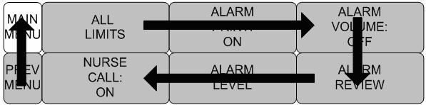
47 Alarm for the Product The machine gives alarm sounds for its system with a related message flashing. LOW -1 Alarm Text LIMITS:The machine enables one to see and change the limits of alarm for all parameter functions. PRINT:with an ON/OFF setup, the related information is printed out whenever an alarm is given. VOLUME:volume of each alarm can be adjusted in 10 step. LEVEL:Priority of each parameter alarm can be set up. REVIEW: Shows the priority order information for all alarms of each measurement. NURSE CALL: Set the ON/OFF feature of the NURSE CALL. ALL LIMITS PRINT: ON VOLUME: OFF NURSE CALL: ON LEVEL REVIEW It is able to see all the alarm range and change of measurement function. Rev ANIMAL/DATA MANAGEMENT 46
48 ALL LIMITS PRINT Set ON/OFF functions automatically. When the alarm is activated the corresponding information is printed on heat sensitive paper. Alarm level must be set to MEDIUM Level or above to print. But, LEAD FAULT AND LOW BATTERY Alarm do not trigger alarm print function. Rev ANIMAL/DATA MANAGEMENT 47
49 VOLUME Set the alarm volume to be set at 10 grades. ALL LIMITS PRINT: OFF VOLUME: OFF NURSE CALL: ON LEVEL REVIEW VOLUME: OFF > OFF 60% 10% 70% 20% 80% 30% 90% 40% 100% 50% LEVEL Set the order of priority in each alarm. ALL LIMITS PRINT: ON VOLUME: OFF NURSE CALL: ON LEVEL REVIEW PARAMETER LEVEL ARRHYTH LEVEL Rev ANIMAL/DATA MANAGEMENT 48
50 PARAMETER LEVEL ARRHYTH LEVEL One can set up priorities when he or she uses the alarm for the diagnostic function. Rev ANIMAL/DATA MANAGEMENT 49
51 REVIEW After an alarm is triggered the alarms and data wave pattern can be reviewed. Set up for priority of each parameter alarm. ALL LIMITS PRINT: ON VOLUME: OFF NURSE CALL: ON LEVEL REVIEW LIST SAVING CONDITION: HIGH Rev ANIMAL/DATA MANAGEMENT 50
52 LIST When an alarm activates, this shows the order of the alarms. LIST SAVING CONDITION: HIGH Rev ANIMAL/DATA MANAGEMENT 51
53 SAVING CONDITION This determines the order in which triggered alarms are saved. LIST SAVING CONDITION: HIGH SAVE CONDITION: LIST > MESSAGE HIGH LOW MEDIUM HIGH Rev ANIMAL/DATA MANAGEMENT 52
54 NURSE CALL When an alarm is triggered, this activated the NURSE CALL function. ALL LIMITS PRINT: ON VOLUME: OFF NURSE CALL: ON LEVEL REVIEW ALL LIMITS PRINT: ON VOLUME: OFF NURSE CALL: OFF LEVEL REVIEW Rev ANIMAL/DATA MANAGEMENT 53
55 BM3Vet User s Manual 3. SETUP 3.1 SETUP DISPLAY DEMO USER SERVICE MAKER SERVICE Rev SETUP 54
56 BM3Vet User s Manual 3.1 SETUP DISPLAY : screen set menu USER SERVICE : This is the menu to set the connection used to interface with an external computer MAKER SERVICE : This is the basic adjustment menu used to adjust the features of this product. DISPLAY USER SERVICE KEY SOUND: ON DEMO: ON MAKER SERVICE DISPLAY SET PARA:Measurement function selected. WAVE SELECT:Set wave pattern source at the bottom of the WINDOW with LARGE PARAMETER MODE. SET DATE & TIME: Set and change date and time. HR SOURCE:Set and select HR/PR source. COLOR SELECT: Set screen display color. SET SWEEP: Set speed of ECG, RESP WAVE DISPLAY Commento [s1]: Wrong picture SET PARA WAVE SELECT: ECG SET DATE & TIME 수정완료. SET SWEEP: 25mm/s HR/PR SELECT: ECG Rev SETUP 55
57 SET PARA Select measurement function to use SET PARA WAVE SELECT: ECG SET DATE & TIME SWEEP SPEED: 25mm/s HR SOURCE: ECG WAVE SELECT Select waveform to display in large parameter display. SET PARA WAVE SELECT: ECG SET DATE & TIME SWEEP SPEED: 25mm/s HR SOURCE: ECG Rev SETUP 56
58 SET PARA SWEEP SPEED: 25mm/s WAVE SELECT: ECG > ECG SPO2 RESP SET DATE & TIME It has sub menu to set date and time. SET PARA WAVE SELECT: ECG SET DATE & TIME SWEEP SPEED: 25mm/s HR SOURCE: ECG SET TIME Set time of equipment. SET TIME SET DATE SET TIME: 10 : 58 : 01 Rev SETUP 57
59 SET DATE Set date of equipment SET TIME SET DATE SET DATE: 06-DEC-2007 HR SOURCE This menu is used to set the source that detects heart and pulse rate. The source can select among ECG and SPO2. Rev SETUP 58
60 SWEEP SPEED Set speed of drawing wave signal pattern in this widow. KEY SOUND Set ON/OFF Key sound of equipment. DEMO Set ON/OFF DEMONSTRATION of equipment. DISPLAY USER SERVICE KEY SOUND: ON DEMO: ON MAKER SERVICE Rev SETUP 59
61 USER SERVICE The user is able to set the communication parameters, power supply filter, and bed number. SET UNIT NAME SYSTEM SET BED NUMBER : 00A AC FILTER: 50HZ SET UNIT NAME Set up for Equipment name. SET UNIT NAME SYSTEM SET BED NUMBER : 00A AC FILTER: 50HZ SET UNIT NAME: Rev SETUP 60
62 SET BED NUMBER Set up for animal bed number. Allowable setters are from 0 to 9 and A to Z. SET UNIT NAME SYSTEM SET BED NUMBER : 00A AC FILTER: 50HZ AC FILTER AC FILTER is function where you can set power supply frequency. This feature is required because power supply frequency can be different from one country to another.. (The selectable frequencies are 50Hz and 60Hz.) SET UNIT NAME SYSTEM SET BED NUMBER : 00A AC FILTER: 50HZ SET UNIT NAME SYSTEM SET BED NUMBER : 00A AC FILTER: 60HZ Rev SETUP 61
63 SYSTEM System able to change and verify Equipment version information and system information MAKER SERVICE Maker service is a menu is used by manufacturers. DISPLAY USER SERVICE KEY SOUND: ON DEMO : ON MAKER SERVICE Rev SETUP 62
64 BM3Vet User s Manual 4. TREND 4.1 TREND GRAPHIC TREND TABLE TREND TREND WINDOW SETUP Rev TREND 63
65 4.1 TREND TREND shows saved data graphically displayed with numeric values. Real-time data recording duration is 1 minute. Amount of saving time is for this data will be saving for 128hours. GRAPHIC TREND TABULAR TREND TREND WINDOW SETUP : Move to main screen : Move within the tables : Move up to other analysis function : Move down to other analysis function : Time(HOURS) period set menu at Graphic Trend : Time(MIN) period set menu at Tabular Trend Rev TREND 64
66 GRAPHIC TREND Wave Data can be stored and seen according to section. GRAPHIC TREND TABULAR TREND TREND WINDOW SETUP 10-SEP :23 II x2 PVC (/min): 0, DOG ST(mm): 0.0 BPM P mmhg GRAPHIC TREND 10-SEP :00 HR(80) III ST( 0.0 ) PVC ( 0 ) RR(20) 300BPM 20.0mm 100/min 150RPM SpO RR II :00 12:30 X X2 Ver.4.00BHCDDC MEDI. 09:30 1 hr 0:57 %SpO RPM C (93) 30S 36.7 Rev TREND 65
67 TIME PERIOD One can set up and store data and time that one can see in a screen. Rev TREND 66
68 TABULAR TREND One can see the stored data at the time previously set up. GRAPHIC TREND TABULAR TREND TREND WINDOW SETUP 10-SEP :30 II x2 PVC (0/min): 0 DOG ST(mm): 0.0 BPM P mmhg III HR SPO2-% SPO2-R SpO2 RESP NIBP-S NIBP-M NIBP-D RR II TEMP II ST PVC 10-SEP 12: SEP 12: SEP 12: SEP 12: SEP 12: X X1 Ver.4.00BHCDDC MEDI. 09:30 1 hr 0:53 %SpO RPM C (93) 30S 36.7 / Rev TREND 67
69 TIME INTERVAL One can store data and set up time. 10-SEP :30 II x2 PVC (0/min): 0 DOG ST(mm): 0.0 BPM P mmhg III HR SPO2-% SPO2-R SpO2 RESP NIBP-S NIBP-M NIBP-D RR II TEMP II ST PVC 10-SEP 12: SEP 12: SEP 12: SEP 12: SEP 12: X X1 Ver.4.00BHCDDC MEDI. 09:30 1 hr 0:53 %SpO RPM C (93) 30S 36.7 TREND WINDOW SETUP Set the trend display window that will show the real time wave window. GRAPHIC TREND TABULAR TREND TREND WINDOW SETUP Rev TREND 68
70 TIME PERIOD Set visible time period in a screen. TIME PERIOD: 30MINS SET TREND PARA TIME PERIOD: 30MINS > 30MINS 60MINS 90MINS 3HOUR 6HOUR 12HOUR Rev TREND 69
71 SET TREND PARA Set parameter for display in a screen. TIME PERIOD: 30MINS SET TREND PARA TREND PRINT Graphic: After display a Graphic Trend on screen and press print to prints the selected trend. Table: After display a Tabular Trend on screen and press print to receive print all the data in the selected animal admit (Admit) table. Rev TREND 70
72 BM3Vet User s Manual 5. ECG 5.1 Outline Color and Name for Each Cable Size ECG Connector Location and Measurement Cable 5 Lead Electrode Attached Location 3 Lead Electrode Attached Location Method to Attach Electrode to Baby 5.2 ECG Data Window 5.3 ECG Data Setup TRACE 1 LEAD SELECT LIMIT QRS VOLUME ECG SIZE HEART RATE SOURCE ECG SPEED ANALYSIS SETTING Rev ECG 71

73 5.1 Introduction It calculates the heart rate with 3 or 5 leads ECG signal acquisition and perform the alarm according to the setting value. Colors and Standards of Cables Leadwire AHA Color code AHA Label IEC Color code IEC Label Right arm White RA Red R Left arm Black LA Yellow L Right leg Green RL Black N Left leg Red LL Green F V1(precordial) Brown V1 White C1 AHA:American Heart Association (U.S.A. standard) IEC:International Electro technical Commission (Europe standard) Position of ECG Connector and Measuring Cable ECG connecter +detect cable Rev ECG 72
74 IEC 3LEAD CABLE AHA 3LEAD CABLE IEC 5LEAD CABLE AHA 5LEAD CABLE Rev ECG 73
75 IEC 3LEAD AHA 3LEAD IEC 5LEAD AHA 5LEAD Rev ECG 74
76 Attaching Electrodes to the Animal 1. Shave excess hair. With a piece of cotton pad moistened with alcohol, clean the animal s skin where the electrodes should be mounted. Avoid wrinkled or uneven skin areas. Wipe off the alcohol with a dry cotton pad. 2. Open the electrode package and take out the electrode. 3. Remove the backing paper from the electrode. Be careful not to touch the adhesive side. 4. Attach the disposable electrode to the previously cleaned skin. Avoid wrinkled and uneven skin areas. 5. The electrode lead which is connected to the monitor onto the electrode. 6. Fasten the electrode lead to the skin with surgical tape with an extra length of wire between the tape and the electrode. This prevents body movement from moving the electrode lead. Note To maintain good contact between the electrode and skin, check that the paste of the disposable electrode is not dry. When contact of the disposable electrode becomes poor, replace the electrode with a new one immediately. Otherwise, contact impedance between the skin and electrode increase and the correct ECG cannot be obtained. If the contact is bed before the expiration date on the package, replace the electrode with a new one. To obtain a stable ECG waveform rub the skin with skin Pure skin preparation gel or tincture of Benzion. Shall use only the CE certified disposable electrode. Rev ECG 75
77 Choosing an ECG lead for Arrhythmia Monitoring It is very important to select a suitable lead for arrhythmia monitoring. Guidelines for non-paced animals: QRS should be tall and narrow(recommended amplitude > 0.5mV) R wave should be above or below the baseline (but not bi-phasic) T wave should be smaller than 1/3 R-wave height. The P-wave should be smaller than 1/5 R-wave height. To prevent detection of P-waves or baseline noises as QRS complexes, the minimum detection level for QRS complexes is set at 0.15mV. Adjusting the ECG wave size on the monitor display(gain adjustment)does not affect the ECG signal which is used for arrhythmia analysis. If the ECG signal is too small, you may get false alarms for asystole. Information on the ECG waveform When ECG signal is 80bpm T-wave duration is 180ms, and the QT interval is 350ms. Rev ECG 76
78 Position of 3-Lead Wire Electrode RA LA LL Rev ECG 77
79 Position of 5-Lead Wire Electrode RA LA V RL LL Rev ECG 78
80 5.2 ECG Data Window BPM P QRS: Detects QRS, and flashes when QRS is detected. 80 Pace Detector Indicators: Detects and displays the animal s pace maker and flashes. Heart Rate Alarm Limit: Decides the QRS limits, and gives an alarm if a value is over the limits. Heart Rate: Displays heart rate per minute. Note ECG Wave Display is always on when the cable is connected. The heart rate is calculated by a moving average. The monitor detects 8 consecutive beats, averages the R-R intervals of the latest 8 beats and uses this average to calculate the current heart rate. When a new beat is detected, the heart rate is recalculated using the latest 8beats. The heart rate display is updated every 3 seconds. Heart rate meter updates a new heart rate for a step increase or decrease in 10 seconds maximum. When ventricular tachycardia is detected, the alarm set in 5 seconds maximum. Check that the delay time of the output signal (alarm trigger 80ms maximum) is within the range of the connected equipment. Rev ECG 79
81 Safety Precautions Warning CABLES Route all cables away from animal's throat to avoid possible strangulation. CONDUCTIVE CONNECTIONS Extreme care must be exercised when applying medical electrical equipment. Many parts of the animal/machine circuit are conductive, such as the animal, connectors, electrodes, transducers. It is very important that these conductive parts do not come into contact with other grounded, conductive parts when connected to the isolated animal input of the device. Such contact would bridge the animal's isolation and cancel the protection provided by the isolated input. In particular, there must be no contact of the neutral electrode and ground. DEFIBRILLATION Do not come into contact with animals during defibrillation. Otherwise serious injury or death could result. To avoid the risk of serious electrical burn, shock, or other injury during defibrillation, all persons must keep clear of the bed and must not touch the animal or any equipment connected to the animal. After defibrillation, the screen display recovers within 10seconds if the correct electrodes are used and applied in accordance with the manufacturer s instructions. ECG cables can be damaged when connected to a animal during defibrillation. Check cables for functionality before using them again. The peak of the synchronized defibrillator discharge should be delivered within 60ms of the peak of the R wave. The signal at the ECG output on the animal monitors is delayed by a maximum of 30ms. If the ECG waveform on the screen is too unstable to synchronize with the animal s heart beat because of the following reason, remove the cause of an alarm, message, or unstable ECG, and then use a stable ECG lead for synchronization. ECG electrode is detached or broken. Lead wire is detached or broken. Lead wire moves. AC interference, EMG noise or noise from ESU is superimposed. Connection cable is broken or has a short circuit. Connector has poor contact. Rev ECG 80
82 INTERFACING OTHER EQUIPMENT Devices may only be interconnected with each other or to parts of the system when it has been determined by qualified biomedical engineering personnel that there is no danger to the animal, the operator, or the environment as a result. In those instances where there is any element of doubt concerning the safety of connected devices, the user must contact the manufacturers concerned (or other informed experts) for proper use. In all cases, safe and proper operation should be verified with the applicable Manufacturer s instructions for use, and system standards IEC /EN must be complied with. Electrosurgery Unit Electrosurgical units(esu) emit a lot of RF interference. If the monitor is used with an ESU,RF interference may affect the monitor operation. Locate the monitor as far as possible from the ESU. Locate them on opposite sides of the operating table, if possible. Connect the monitor and ESU to different AC outlets located as far as possible from each other. When using this monitor with an electrosurgical unit, its return plate and the electrodes for monitoring must be firmly attached to the animal. If the return plate is not attached correctly, it may burn the animal s skin where the electrodes are attached. Rev ECG 81
83 5.3 ECG Data Setup A setup window appears at lower part of the screen when the Trim Knob Key is pressed in the ECG Parameter Window. Selection is made by pressing the Trim Knob Key, while movement across the menu is performed by turning the key either clock or anticlockwise. LEAD SELECT : II DISPLAY ANALYSIS SETTING QRS VOLUME : OFF TRACE 1 LEAD SELECT Selection for display is made from channels I to V by moving the key left or right. LEAD SELECT : II DISPLAY ANALYSIS SETTING QRS VOLUME : OFF LEAD SELECT : II > I avr II avl III avf V Rev ECG 82
84 LIMIT Alarm Limit is 0 ~ Move the mark to select RETURN or HR, and press. 2. If pressed at HR, move to LOW, and press. 3. Checking the color changing, move right or left to select the value to set up, and press. 4. Press at HIGH. Checking the color changing, move again to select the value to set up, and press. Move to HR, and press again. (You may decide to perform in the LOW HIGH order, which produces same result.) 5. Select RETURN to get out of the window. Rev ECG 83
85 SOUND Set ON/OFF of ECG alarm sound. LEAD SELECT : II DISPLAY ANALYSIS SETTING QRS VOLUME : OFF LIMIT SOUND Rev ECG 84
86 QRS VOLUME Move the Key to select a volume rate from OFF, 10% to 100%. QRS VOLUME : OFF > OFF 60% 10% 70% 20% 80% 30% 90% 40% 100% 50% DISPLAY Set the sweep speed and waveform size. LEAD SELECT : II DISPLAY ANALYSIS SETTING QRS VOLUME : OFF Rev ECG 85
87 ECG SPEED ECG speed is 25 mm/s. Speed is changeable to 6.25, 12.5, 25, 50mm/s. ECG SIZE The size is changeable to X0.5, X1, X2, X4. SWEEP SPEED : 25 mm/s ECG SIZE : X1 x 0.25 x 0.5 > x 1 x 2 x 4 Rev ECG 86
88 HR SOURCE SWEEP SPEED : 25 mm/s ECG SIZE : X1 HR SOURCE: ECG SWEEP SPEED : 25 mm/s HR SOURCE: ECG > ECG SPO2 ANALYSIS SETTING Analysis setting divided to 3 menus. ECG FILTER:One may select from three frequency types for WAVE FILTER. MONITOR 0.5Hz ~ 40Hz MODERATE 0.5Hz ~ 25Hz MAXIMUM 5Hz ~ 25Hz DIAGNOSIS 0.5Hz ~ 150Hz LEAD SELECT : II DISPLAY ANALYSIS SETTING QRS VOLUME : OFF Rev ECG 87
89 ECG FILTER : MONITOR PACE : OFF ARRHYTHM : OFF PVC SETTING ST SETTING ECG FILTER : MONITOR > MONITOR MODERATE MAXIMUM DIAGONOSIS PACE:Sets up ON/OFF to indicate that the animal has PACE. The PACE menu option enables/disables the pacemaker detection program. ECG FILTER : MONITOR PACE : OFF ARRHYTHM : OFF PVC SETTING ST SETTING Be aware of the following when monitoring a animal with a pacemaker. ARRHYTH:Sets up ON/OFF to indicate detection of diagnosis (ASYS, VTAC/VFIB, VTAC). The Analysis algorithm simultaneously uses leads I, II, III, and the V lead for ECG and arrhythmia analysis. Rev ECG 88
90 ECG FILTER : MONITOR PACE : OFF ARRHYTHM : OFF PVC SETTING ST SETTING ASYSTOLE: Ventricular asystole occurs whenever the displayed heart rate drops to zero. VTAC/VFIB: Ventricular fibrillation occurs when the ECG waveform indicates a chaotic ventricular rhythm with an average heart rate greater than or equal to 200beats per minute. VTAC: Ventricular tachycardia occurs when a run of six or more ventricular beats is detected With an average heart rate greater than or equal to 150beats per minute. ST SETTING : ST signal and settings related to ST menu. ECG FILTER : MONITOR PACE : OFF ARRHYTHM : OFF PVC SETTING ST SETTING ST ANALYSIS: ON/OFF ST analysis signal. ST ANALYSIS : ON MEASUREMENT CONDITION ST LIMIT ST LEVEL Rev ECG 89
91 MEASUREMENT CONDITION: ST measurement condition setting ST ANALYSIS : ON MEASUREMENT CONDITION ST LIMIT ST LEVEL ST LIMIT: ST alarm limit range setting Rev ECG 90
92 ST LEVEL: LEVEL setting Rev ECG 91
93 PVC SETTING: PVC ON/OFF and limit range setting ECG FILTER : MONITOR PACE : OFF ARRHYTHM : OFF PVC SETTING ST SETTING PVC ANALYSIS: Decision maker to display PVC value sign with ON/OFF PVC ANALYSIS : ON PVC LIMIT PVC LEVEL PVC LIMIT: Set alarm indicate to PVC Rev ECG 92
94 PVC LEVEL: Set PVC LEVEL Warning Display Heart Beat Equipment Signal Heart Beat equipment signal displays when the PACE mode is on. The signal size or form are meaningless clinically. Number Of Heart Beats When using PACE mode, be sure to use an alternative method to monitor the heart rate. The heart beat equipment can show heart beat even during arrhythmia continuously. Therefore, do not depend on heart beat alarm excessively. Rev ECG 93
95 BM3Vet User s Manual CAUTION FDA POSTMARKET SAFETY ALERT The United States FDA Center for Device and Radiological Health issued a safety bulletin October 14, this bulletin states that minute ventilation rate-adaptive implantable pacemakers can occasionally interact with certain cardiac monitoring and diagnostic programmed rate. The FDA further recommends precautions to take into consideration for animals with these types of pacemakers. These precautions include disabling the rate responsive mode and enabling an alternate pace mode. For more information contact: Office of Surveillance and Biometrics, CDRH, FDA 1350 Packard Drive, Mail Stop HFZ-510 Rockville, MD U.S.A NOTE ECG monitoring with animals in non-invasive trans coetaneous pacemakers may not be possible due to large amounts of energy produced by these devices. Monitoring ECG with an external device may be needed. Rev ECG 94
96 WARNINGS VENTRICULAR ARRHYTHMISAS The arrhythmia analysis program is intended to detect ventricular arrhythmias. It is not designed to detect a trial or supra ventricular arrhythmias. Occasionally it may incorrect identify the presence or absence of an arrhythmia. Therefore, a physician must analyze the arrhythmia information in conjunction with other clinical findings. SUSPENDED ANALYSIS Certain conditions suspend arrhythmia analysis. When suspended, arrhythmia conditions are not detected and alarms associated with arrhythmias do not occur. The messages which alert you to the conditions causing suspended arrhythmia analysis are : ARR OFF, ARRHYSUSPEND, LEADS FAIL, PAUSE, ALL S OFF, and DISCHARGED. FALSE CALLS False low heart rate indicators or false asystole calls may result with certain pacemakers because of electrical overshoots. MONITERING PACEMAKER PATIENTS Monitoring of pacemaker patients can only occur with the pace program activated. PACEMAKER SPIKE An artificial pacemaker spike is displayed in place of the actual pacemaker spike. All pacemaker spikes appear uniform. Do not diagnostically interpret pacemaker spike size and shape. PATIENT HAZARD A pacemaker pulse can be counted as a QRS during a systole in either pace mode. Keep pacemaker patients under close observation. RATE METERS Keep pacemaker patients under close observation. Rate meters may continue to count the pacemaker rate during cardiac arrest and some arrhythmias. Therefore, do not rely entirely on rate meter alarms. Rev ECG 95
97 Trouble shooting Problem : Inaccurate heart rate and/or false asystole. Solution : Check ECG signal from animal: 1. Check/adjust lead placement. 2. Check/perform skin preparation. 3. Check/replace electrodes. Check amplitude of ECG waveform: 1. Select ECG parameter label. 2. Select DISPLAY LEAD, 3. Scroll through all ECG leads and check for 0.5mV amplitude at normal (1X) size. (at least 0.5mV amplitude is required for QRS detection.) for borderline signals, validate on a graph. 4. If amplitudes are low, electrodes may need to be repositioned or replaced. Problem : False ventricular calls. Solution : Check ECG signal from animal: (the chest lead may exhibit polarity changes which may occasionally cause an inaccurate call.) 1. Check/adjust lead placement. 2. Check/perform skin preparation. 3. Check/replace electrodes. (if chest lead is a problem, move the chest lead to another chest position or leg position.) Rev ECG 96
98 Problem : Inaccurate pacemaker detection Solution : Use pacemaker processing: 1. Select ECG parameter label. 2. Display the lead of ECG with the greatest amplitude in the top waveform position. 3. Select ANALYSIS SETTINGS. 4. SELECT DETECT PACE. Rev ECG 97
99 BM3Vet User s Manual 6. SpO Outline SpO2 Connector Location and Measuring Cable 6.2 SpO2 Data Window 6.3 SpO2 Data Setup SWEEP SPEED RATE VOLUME LIMIT Rev SpO2 98

100 6.1 Outline SPO2 monitoring is a noninvasive technique used to measure the amount of oxygenated hemoglobin and pulse rate by measuring the absorption of selected wavelengths of light. The light generated in the probe passes through the tissue and is converted into an electrical signal by the photodetector in the probe. The monitor processes the electrical signal and displays on the screen a waveform and digital values for SpO2 and pulse rate. It detects SpO2 in the way of transmitting the red and infrared rays into the capillary vessel to take the pulsation. Also performs the alarm function according to the setting values. SpO2 Connector Location and Measuring Cable SpO 2 connector Rev SpO2 99
101 Position of SpO 2 Probe Note The signal input is a high-insulation port and it is defibrillator proof ( ) The insulated input ensures animal safety and protects the device during defibrillation and electrosurgery. Rev SpO2 100
102 BM3Vet User s Manual 6.2 SpO2 Data Window SpO 2 Alarm Limit: Indicates an SpO 2 alarm limit SpO 2 Strength indicators: Oxygen Concentration in the Indicates SpO 2 Strength in a bar Blood(SpO2 value) graph. : Indicates %SpO 2 in numbers. The current SPO2 value and the derived pulse rate (RATE) are displayed. The block sets indicate the strength of the signal (twenty block bars indicate the strongest signal). The SPO2 measurements are averaged over a 6-second period of time. The monitor display is updated every second. The SPO2 monitoring features are found in the SPO2 menu. These features include alarm limit adjustment, display of RATE, and RATE volume. Note SpO 2 WAVE SIZE is changed automatically. Rev SpO2 101
103 Signal and Data Validity It is extremely important to determine that the probe is attached to the animal correctly and the data is verifiable. To make this determination, three indications from the monitor are of assistance signal strength bar, quality of the SPO2 waveform, and the stability of the SPO2 values. It is critical to observe all three indications simultaneously when ascertaining signal and data validity. Signal Strength Bar The signal strength bar is displayed within the SPO2 values window. This bar consists of 20 blocks set depending on the strength of the signal. Proper environmental conditions and probe attachment will help to ensure a strong signal. Quality of SPO2 Waveform Under normal conditions, the SPO2 waveform corresponds to (but is not proportional to) the arterial pressure waveform. The typical SPO2 waveform indicates not only a good waveform, but helps the user find a probe placement with the least noise spikes present. The figure below represents an SPO2 waveform of good quality. Good Quality SPO2 Waveform If noise (artifact) is seen on the waveform because of poor probe placement, the photodetector may not be flush with the tissue. Check that the probe is secured and the tissue sample is not too thick. Pulse rate is determined from the SPO2 waveform which can be disrupted by a cough or other hemodynamic pressure disturbances. Motion at the probe site is indicated by noise spikes in the normal waveform. (See the figure below.) SPO2 Waveform with Artifact Rev SpO2 102
104 Stability of SPO2 Values The stability of the displayed SPO2 values can also be used as an indication of signal validity. Although stability is a relative term, with a small amount of practice one can get a good feeling for changes that are artifactual or physiological and the speed of each. Messages are provided in the SPO2 values window to aid you in successful SPO2 monitoring. WARNING In the monitoring of animals the coincidence of adverse conditions may lead to a disturbed signal going unnoticed. In this situation artifacts are capable of simulating a plausible parameter reading, so that the monitor fails to sound an alarm. In order to ensure reliable animal monitoring, the proper application of the probe and the signal quality must be checked at regular intervals. Rev SpO2 103
105 6.3 SpO 2 Data Setup : Menu in which SpO 2 Alarm are set up. RATE VOLUME:Menu in which RATE VOLUME is set up RATE VOLUME: OFF RATE VOLUME Move the KEY to select the volume from OFF to 100%. When the ECG volume rate is set, it turns OFF automatically. RATE VOLUME: OFF RATE VOLUME: OFF > OFF 60% 10% 70% 20% 80% 30% 90% 40% 100% 50% Rev SpO2 104
106 Two menus: LIMIT, SOUND provided in the alarm menu RATE VOLUME: OFF LIMIT Number setting of alarm value of %SpO2 is 0 ~ Move the mark to select from RETURN, SpO2 or SpO2-R, and press. 2. After pressing at SpO2, move the cursor right or left to LOW, and press. 3. Once the color is changed, move the cursor again to the selected value and press. 4. Place the cursor to HIGH and press, when the color changes, move the cursor again to select the targeted value, and press. Finally move to SpO2 and press. (You may decide to perform the process in the opposite order, LOW to HIGH, to have the same result.) 5. After pressing at SpO2-R, move the cursor right or left to LOW, and press. 6. Once the color is changed, move the cursor again to the selected value and press. 7. Place the cursor to HIGH and press, when the color changes, move the cursor again to select the targeted value, and press. Finally move to SpO2-R and press. 8. With the selection of RETURN the user gets out of the menu. LIMIT SOUND: ON Rev SpO2 105
107 SOUND Warning sound or message displays configuration menu when an alarm is triggered. LEAD FAULT Condition When using a reusable lingual probe, there is a system alarm to alert you when the probe is off the Monitor. The monitor defaults this LEAD FAULT condition as a System Warning alarm. however, You can set it as a System LEVEL in Monitor Defaults. Rev SpO2 106
108 SPO2 Messages Below is a list of system status alarm messages which may be displayed in the SPO2 parameter window during monitoring. CHECK PROBE Reusable lingual probe is off the animal. Check the probe. The factory default for this alarm is MESSAGE. PULSE SEARCH Detection by the monitor of a repeatable pulse has ceased. Check the animal and the probe site. POOR SIGNAL The SPO2 signal is too low. No SPO2 data is displayed. This can be due to a low animal pulse, animal motion, or some other interference. Check the animal and the probe. LOST SIGNAL SPO2 data continues to be displayed, but the quality of the signal is questionable. Check the animal and the probe. ARTIFACT The SPO2 signal is patient's motion artifact and noise Rev SpO2 107
109 BM3Vet User s Manual 7. RESPIRATION 7.1 Outline Respiration Connector and Measuring Cable 7.2 RESPIRATION Data Window 7.3 RESPIRATION Data Setup Respiration Size Alarm Limit Rev RESPIRATION 108

110 7.1 Outline Respiration via ECG Lead II electrode makes the skin area of the chest enlarged, causing changes in the resistance of skin. Through this it calculates respiration value per minute and performs the alarm function according to limit value. Respiration Connector and Measuring Cable Respiration Connecter Respiration Measuring Cable Rev RESPIRATION 109
111 IEC 3LEAD CABLE AHA 3LEAD CABLE IEC 5LEAD CABLE AHA 5LEAD CABLE Rev RESPIRATION 110
112 IEC 3LEAD AHA 3LEAD IEC 5LEAD AHA 5LEAD Rev RESPIRATION 111
113 7.2 Respiration Data Window Breathe indicator: Indicates the detected breath Apnea Limit Setting: Apnea limit sign RPM 30S 20 Respiration alarm limit: Indicates respiration limits. Breathing Number: Displays the number of respiration per minute. Rev RESPIRATION 112
114 7.3 Respiration Data Setup : Respiration alarm setting menu RESP SIZE: A menu to setup Wave Display SWEEP SPEED: A menu to setup Wave Display of speed APNEA DETECT: A menu to setup APNEA alarm display APNEA DETECT : ON SWEEP SPEED : 25mm/s RESP SIZE : X 2 RESPIRATION SPEED Wave pattern speed is 25 mm/s. SWEEP SPEED : 12.5mm/s RESP SIZE : X 2 APNEA DETECT : ON APNEA DETECT : ON SWEEP SPEED: 12.5mm/s 6.25 mm/s > 12.5 mm/s 25 mm/s Rev RESPIRATION 113
115 RESPIRATION Set wave pattern size X2~ X10. APNEA DETECT : ON SWEEP SPEED : 12.5mm/s RESP SIZE : X 2 APNEA DETECT Deciding function of activating Apnea Alarm APNEA DETECT : ON SWEEP SPEED : 12.5mm/s RESP SIZE : X 2 APNEA DETECT : OFF SWEEP SPEED : 12.5mm/s RESP SIZE : X 2 Rev RESPIRATION 114
116 Alarm menu provide LIMIT and. APNEA DETECT : ON SWEEP SPEED : 12.5mm/s RESP SIZE : X 2 LIMIT Alarm Limit of Respiration Numeric Value is 5 ~ 150bpm Alarm Limit of RESPIRATION APNEA Numeric Value is 3 ~ 30sec. LIMIT SOUND : ON 1. Move the mark to select RETURN, RESP or RESP-A, and press. 2. After a press in RESP, move the cursor right or left to LOW, and press. 3. After the color changed, move the cursor right or left to the selected value, and press. 4. Place the cursor to HIGH, and press. When the color has changed, move the cursor again to select the value and press. Move to the RESP and press again. (You may decide to perform the process in the opposite order, LOW to HIGH, to have the same result.) 5. Once RESP-A is pressed, move to LOW and press. 6. When the color has changed, move the cursor to select the value, and press. 7. A press in the HIGH position, the color changes. Then move the cursor to select the value and press. Move again to RESP-A, and press. 8. Select RETURN to get out of the window. Rev RESPIRATION 115
117 SOUND Warning sound or message displays activation setting when Respiration ALRAM occurs. LIMIT SOUND : ON LIMIT SOUND : OFF Rev RESPIRATION 116
118 BM3Vet User s Manual 8. NIBP 8.1 Outline NIBP Connector Location and Cuff 8.2 NIBP Data Window 8.3 NIBP Data Setup LIMIT CUFF SIZE UNIT SELECT INTERVAL INFLATION Rev NIBP 117

119 8.1 Outline This function is to measure minimum, Maximum and average blood pressure by using Oscillometric method Position of NIBP Connecter and cuff NIBP Connector LARGE CUFF Note As the value of NIBP can vary according to the age and sex of an animal, the user needs to set up correct data in Parameter Menu before measurement. WARNING Noninvasive blood pressure monitoring is not recommended for animals with hypotension, hypertension, arrhythmias or extremely high or low heart rate. The software algorithm cannot accurately compute NIBP or animals with these conditions. Rev NIBP 118
120 CAT CUFF Placement DOG CUFF Placement Note As the value of NIBP can vary according to the age and sex of a animal, the user needs to set up right data in parameter Menu before measurement. Tubes between the cuff and the monitor are not kinked or blocked. The air pad should be exactly over the branchial artery. Tubing is immediately to the right or left of the branchial artery to prevent kinking when elbow is bent. Rev NIBP 119
121 The routine maintenance is performed every 2 years. Check the following list to ensure device operates properly and safety at all times. 1. Check for proper cuff size. 2. Check for residual air left in the cuff from a previous measurement. 3. Make sure cuff is not too tight or too loose. 4. Make sure cuff and heart are at same level, otherwise hydrostatic pressure will offset the NIBP value. 5. Minimize animal movement during measurement. 6. Check for leak in cuff or tubing. 7. Animal may have a weak pulse. Rev NIBP 120
 Systolic pressure: Indicates the maximum limit of blood pressure Diastolic blood")
122 8.2 NIBP Data Window Alarm Limit:Indicates alarm limit of blood pressure. Measurement time Indicates the completion time of measuring mmhg ADT 09:30 1 HR 0: (93) Systolic pressure: Indicates the maximum limit of blood pressure Diastolic blood pressure:indicates the minimum limit of blood pressure Interval Time: Indicates Interval time when measures the blood pressure periodically Measure time: Indicates the schedule counter time of measuring Mean Value: Indicates mean blood pressure Rev NIBP 121
123 8.3 NIBP Data Setup : A menu to set the Alarm CUFF SIZE:A menu to select cuff size UNIT SELECT: A menu to select the pressure unit INTERVAL :A menu to set Interval time when measures the blood pressure periodically INFLATION: Initial Pressurization setting menu UNIT SELECT: mmhg INFLATION: 170mmHg CUFF SIZE: ADT INTERVAL: OFF The alarm provides LIMIT and. UNIT SELECT: mmhg INFLATION: 170mmHg CUFF SIZE: ADT INTERVAL: OFF LIMIT SOUND: ON Rev NIBP 122
124 LIMIT Alarm setting Numeric Value of Systolic, Diastolic, and mean pressure is 10 ~ 360mmHg. 1. Move the mark to select one from RETURN, NIBP-S, NIBP-M, or NIBP-D, and press. 2. Press the key at NIBP-S, and move to LOW, and press again.(the user gets the same result regardless of the LOW-HIGH, or HIGH-LOW order.) 3. When the color has changed, move it again to select a target value, and press. 4. Press the key at HIGH. When the color has changed, move to the right to select a target value, and press. 5. Set up or revise the values of NIBP-M and NIBP in the same way as above. 6. With the selection of RETURN, the user can get out of the window. LIMIT SOUND: ON Rev NIBP 123
125 SOUND The menu which decides activation of warning signs and message displays when the respiration alarm is on. LIMIT SOUND: ON CUFF SIZE The user can select a CUFF between LARGE and SMALL. Rev NIBP 124
126 UNIT SELECT It is a function to set blood pressure measurement unit. The blood pressure measurement unit provides mmhg and kpa. INTERVAL This menu is used for selecting intervals when measures the blood pressure automatically. Select a target interval from 1min, 2, 3, 4, 5, 10, 15, 20, 30, 1hour, 2, 4, 8. Rev NIBP 125
127 INFLATION It is a function for pressurization pressure. Numeric value is 80 ~ 240 (10mmHg / step) CUFF SIZE: MEDIUM UNIT SELECT: kpa INFLATION: 140mmHg INTERVAL: OFF CUFF SIZE: MEDIUM UNIT SELECT: mmhg INFLATION: 80mmHg INTERVAL: OFF CUFF SIZE: MEDIUM UNIT SELECT: mmhg INFLATION: 240mmHg INTERVAL: OFF Warning Pay attention to not to block connecting hose when you put cuff on animal. Rev NIBP 126
128 BM3Vet User s Manual 9. TEMPERATURE 9.1 Outline Temperature Connector and Measuring Cable 9.2 Temperature Data Window 9.3 Temperature Data Setup LIMIT UNIT SELECT Rev TEMPERATURE 127

129 BM3Vet User s Manual 9.1 Outline This function is used to indicate the changes of resistance generated by the changes of temperature in numbers. The function involves the process of transferring the changes into electric signals. Temperature Connector and Measuring Cable Temperature Connector Temperature Measuring Cable Rev TEMPERATURE 128
130 9.2 Temperature Data Window Unit: Displays temperature unit. Temperature: Displays temperature. Alarm limit on the least low temperature : Indicates temperature limits Note The minimum measuring time required to obtain accurate readings at the specific animal site is at least 3 minutes. Rev TEMPERATURE 129
131 9.3 Temperature Data Setup : Temperature measurement alarm set UNIT: Temperature measurement unit set UNIT SELECT: C Alarm menu provide LIMIT and. LIMIT SOUND : ON LIMIT Setting numeric value is 15.0 ~ Move the mark to select either RETURN or TEMP, and press. 2. After pressing the cursor at TEMP, move it to LOW, and press. 3. When the color has changed, move the cursor again to select a target value, and press. 4. Move the cursor to HIGH and press. After the color has changed, move the cursor again to select a target value, and press. (One may choose HIGH first to get the same result.) 5. Select RETURN to get out of the menu. Rev TEMPERATURE 130
132 LIMIT SOUND : ON SOUND The menu which decides activation of warning signs and message displays when the respiration alarm is on. LIMIT SOUND : ON Rev TEMPERATURE 131
133 LIMIT SOUND : OFF UNIT SELECT Able to select unit with C, F. UNIT SELECT: C UNIT SELECT: F Rev TEMPERATURE 132
134 BM3Vet User s Manual 10. PRINT 10.1 Print Printer and Heat Sensitivity Paper Function and Setup Menu 10.2 Paper Change Rev PRINT 133

135 10.1 Print Printer and Heat Sensitivity Paper A printer used to print data onto thermal paper. Size of the thermal paper roll: 580mm wide x 380mm in diameter any thermal paper of same size can be used for the printer. Side View of Printer Rev PRINT 134
136 Function and Setup Menu PRINTER SPEED: 25mm/s WAVE FORM3: SPO2 WAVE FORM2: RESP WAVE FORM1: ECG 1. Press the PRINT Key for continuous printing. 2. Select Printing Speed 25, 50 mm/s. PRINTER SPEED: 25mm/s WAVE FORM3: SPO2 WAVE FORM2: RESP WAVE FORM1: ECG PRINTER SPEED: 50mm/s WAVE FORM3: SPO2 WAVE FORM2: RESP WAVE FORM1: ECG 3. Set up PRINT in the MORE menu to activate during printing. PRINT ON 4. Data is printed in a selected wave form along with personal information of the animal. 3 channels select 3 parameters to print. PRINTER ECG, RESP, SPO2 Rev PRINT 135
137 PRINTER SPEED: 50mm/s WAVE FORM3: SPO2 WAVE FORM2: RESP WAVE FORM1: ECG PRINTER SPEED: 50mm/s WAVE FORM3: SPO2 WAVE FORM2: RESP WAVE FORM1: ECG Rev PRINT 136
138 PRINTER SPEED: 50mm/s WAVE FORM3: SPO2 WAVE FORM2: RESP WAVE FORM1: ECG Rev PRINT 137


139 10.2 Paper Change 1 Open the window of the printer. 2 Insert the paper roll offered with the product into the printing unit. Place the roll in a proper way so that the printed paper can roll out upwards. 3 Press the printer window until it is properly shut. Inaccurate shutting may cause failure in printing. Rev PRINT 138
1 Appendix - Product Specifications
 1 Appendix - Product Specifications WARNING The patient monitor may not meet its performance specification if stored or used outside the manufacturer s specified temperature and humidity range. 1.1 Safety
BM3 User s Manual. Patient Monitor. Rev. 2.61
 Patient Monitor Rev. 2.61 Table of Contents Table of Contents... 1 1. BASIC... 11 1.1 CE Standard Information... 12 1.2 Read before Use... 13 How to Contact Us... 13 Warranty Period... 14 Warning, Caution,
Atlas Monitor Outline Train the Trainer
 Atlas Monitor Outline Train the Trainer A. ATLAS Monitor 1. Atlas Monitor is not designed for use on children younger than 3 years old. 2. Weight: 9.5lbs to 13.2 lbs, depending on configuration 3. Variable
Propaq LT Outline Train the Trainer
 Train the Trainer A. Propaq LT and LTR Propaq LT Standalone monitor Propaq LTR Monitor that has the wireless Acuity feature enabled 1. Lightweight (Less than 2 pounds) 2. Uses rechargeable lithium ion
ANGELUS (Ver 2.03) Patient Monitoring System
 Patient Monitoring System") ANGELUS (Ver 2.03) Patient Monitoring System CONTENT Contents of Manual 1 Meaning of Symbols used in this manual 2 Section 1. GENERAL 3 1.1 Introduction 4 1.2 Composition of unit 8 1.3 Panel Description
ANGELUS (Ver 2.03) Patient Monitoring System CONTENT Contents of Manual 1 Meaning of Symbols used in this manual 2 Section 1. GENERAL 3 1.1 Introduction 4 1.2 Composition of unit 8 1.3 Panel Description
DPM Summary of Features and Benefits
 Summary of Features and Benefits PAT I E N T M O N I TO R 12.1" TFT display, configurable up to 8 waveforms, enables maximum data analysis of your most critical parameters Standard features include 3/5-lead
Vitalmax 4000 CL Product Specifications
 Page 1 of 5 Vitalmax 4000 CL 510 Garden Avenue North, Clearwater, FL 33755 Phone: (727) 442-8118 Fax: (727) 443-7257 A. Mechanical Description Size 10" H x 13" W x 8"D (25 cm x 33 cm x 20 cm) Weight 18
Transport Pro Patient Monitor Operator s Manual Software Version 2.1
 GE Healthcare Transport Pro Patient Monitor Operator s Manual Software Version 2.1 Transport Pro English 2024598-003 (CD) 2024579-020A (paper) 2007 General Electric Company. All rights reserved. The information
User s Guide. Cardell Touch Veterinary Vital Signs Monitor. For Models:
 Cardell Touch Veterinary Vital Signs Monitor For Models: 8013-001 8013-002 8013-003 8013-004 User s Guide TP200 Rev. A 003-2840-00 Rev. AA2 (6/20/18) Software Version V4.0.X Product Information Dealer:
Omni (K) PATIENT MONITOR
 PATIENT MONITOR") Omni (K) PATIENT MONITOR Omni (K) Intuitive Designed for a fast paced work environment, the Infinium Omni (K) patient monitor offers an extremely simple and adaptable user interface. Patient information
Omni (K) PATIENT MONITOR Omni (K) Intuitive Designed for a fast paced work environment, the Infinium Omni (K) patient monitor offers an extremely simple and adaptable user interface. Patient information
T1 BEDSIDE MONITOR GUIDELINE
 APPENDIX A T1 BEDSIDE MONITOR GUIDELINE 5.23 Software Version This document is a guideline only to be used as an aid to comprehensive Inservice training. NAME: HOSPITAL: DATE: VALIDATOR: A. OVERVIEW 1.
OMNI TOUCH SCREEN PATIENT MONITOR
 OMNI TOUCH SCREEN PATIENT MONITOR OMNI Intuitive Designed for a fast paced work environment, the Infinium Omni patient monitor offers an extremely simple and adaptable user interface. Patient information
M9500 Patient Monitor User s Manual
 M9500 Patient Monitor User s Manual Guangdong Biolight Meditech Co., Ltd. Address: Innovation First Road, Technology Innovation Coast, Jinding, Zhuhai, P.R.CHINA Tel: +86-756-3399900 Fax: +86-756-3399989
FC1400 Operation Manual
 FC1400 Operation Manual Ver. 2.03 2016.08.23 www.ebionet.com Warranty Period This product is manufactured and passed through strict quality control and through inspection. Compensation standard concerning
Passport 12m and Passport 17m BEDSIDE MONITOR GUIDELINE 5.21 Software Version NAME: HOSPITAL: DATE: VALIDATOR: Performed
 Passport 12m and Passport 17m BEDSIDE MONITOR GUIDELINE 5.21 Software Version This document is a guideline only to be used as an aid to comprehensive Inservice training. NAME: HOSPITAL: DATE: VALIDATOR:
Manufacturer s Responsibility Only under the following circumstances will manufacturer be responsible for the safety, reliability and performance of t
 Preface Thank you for using M9500 patient monitor. In order to enable you to skillfully operate Monitor as soon as possible, we provide this user s manual with delivery. When you install and use this instrument
PATIENT MONITORING SYSTEMS
 PATIENT MONITORING SYSTEMS PATIENT MONITORING SYSTEMS The benefits of HEYER Scalis to meet the market situation HEYER Scalis function & features make it fit to match the requirement of standard applications
OPERATOR S MANUAL. Patient Monitor M20. EU representative TECNOMED 2000 S.L. Valencia, Madrid Spain
 OPERATOR S MANUAL Patient Monitor M20 EU representative TECNOMED 2000 S.L. Valencia, 25-28012 Madrid Spain Manufacturer Mediana Co., Ltd. Wonju Medical Industry Park, 1650-1 Donghwa-ri, Munmak-eup, Wonju-si,
Multi-Parameter Patient Monitor
 KIZLON Multi-Parameter Patient Monitor Email: info@kizlonmedical.com Website: www.kizlonmedical.com Multi-Parameter Patient Monitor KPM-A1 Series s of Portable Patient Monitor KPM-A1 Series has color TFT
PATIENT MONITORING SYSTEMS
 PATIENT MONITORING SYSTEMS Patient Monitoring Systems DESIGN FEATURES HEYER VizOR is our premium solution for sophisticated patient monitoring applications. VizOR comes in its standard configuration with
PATIENT MONITORING SYSTEMS
 PATIENT MONITORING SYSTEMS Patient Monitoring Systems DESIGN FEATURES HEYER VizOR is our premium solution for sophisticated patient monitoring applications. VizOR comes in its standard configuration with
PM-9000 Express Portable Patient Monitor
 FEATURES 12.1" color TFT with maximum 8 waveforms Rich in ECG software OxyCRG software available 40 seconds full-disclosure waveforms review Drug dose calculation Bed to bed view Networking capacity Multi-Gas/O2
General Skills. yes. Device controls, buttons, indicators, and connectors
 HeartStart MRx Skills Checklist This checklist assesses qualified medical personnel s understanding of MRx operation after instructor-based training. Perform a quick skills assessment using the General
OPERATOR S MANUAL. NPB-4000/4000C Patient Monitor
 OPERATOR S MANUAL NPB-4000/4000C Patient Monitor Nellcor Puritan Bennett Inc. is an affiliate of Tyco Healthcare. Nellcor, Nellcor Puritan Bennett, Durasensor, C-LOCK, Oxisensor II, Dura-Y, and the Nellcor
SpotOn Temperature Monitoring System. SpotOn. Temperature Monitoring System. Model 370 Installation and Service Manual
 3 SpotOn Temperature Monitoring System Model 370 Installation and Service Manual Please forward to the Biomedical Engineering Department 3M SpotOn Temperature Monitoring System Revision History Revision
Patient Monitoring System YM5500. Service Manual
 Patient Monitoring System YM5500 Service Manual SERVICE MANUAL For YM5500 Patient Monitor Mediana Co.,Ltd. 231-6 Nonhyun-Dong, Kangnam-Ku, Seoul, Korea Tel: (82) 2 542 3375 Fax: (82) 2 542 7447 YM5500
T1 Monitor/Module Default Settings
 Hospital, City, ST Department Clinical/Sales/Service Representatives Date Software Version Signature,Title Maintenance System time Date format: Time format: 12 24 Manage Config Department: General Select
End-Tidal CO2 User Guide CAPNO3 T NIBP. SpO2. Ver Charmcare Co., Ltd.
 End-Tidal CO2 User Guide CAPNO3 T NIBP EtCO2 ECG SpO2 Ver 2.00 Charmcare Co., Ltd. -1- Table of Contents Indications for use statement 4 Warranty 4 Battery Replacement 4 Contact Us 5 Definition of Terms
BeneVision TM80 Telemetry Monitor
 Telemetry Monitor Note: The TM80 is not intended as a replacement to the Operating Instructions. Prior to operating equipment, the user must be familiar with the Operating Instructions Manual contents.
Checkout Procedure Manual
 Checkout Procedure Manual A-1020818 REV1 SmartMonitor2 Checkout Procedure 2015 Circadiance LLC. All rights reserved. Table of Contents Introduction... 2 Required Equipment... 2 Important Notes Read Carefully...
VS2000V Veterinary Vital Signs Monitor Operation Manual
 VS2000V Veterinary Vital Signs Monitor Operation Manual - English Version 1.0, July 2011 2011 UTECH Co., Ltd. All rights reserved. Table of Contents Table of Contents Warranty and Service Information...
Veterinary Portable Multi-parameter Patient Monitor. Operation Manual
 Veterinary Portable Multi-parameter Patient Monitor Operation Manual Content Chapter 1 Introduction... 1-1 1.1 General Information... 1-3 1.2 Screen Display... 1-4 1.3 Button Functions and Basic Operation...
Product Specifications
 1.Safety Specifications 1.1Product Classification Class Type of protection against electric shock Specification Class I, with internal power supply Degree of protection against electric shock Anti-defibrillation:
M8000VET /M9000VET Veterinary Monitor User s Manual
 M8000VET /M9000VET Veterinary Monitor User s Manual Guangdong Biolight Meditech Co., Ltd. Address: Innovation First Road, Technology Innovation Coast, Jinding, Zhuhai, P.R.CHINA Tel: +86-756-3399900 Fax:
CLEO VERSATILITY IN VITAL SIGNS
 CLEO VERSATILITY IN VITAL SIGNS CLEO PORTABLE weighs less than 3 lbs TOUCHSCREEN easy and intuitive to use MOBILE backup battery powered The Cleo is a new and intuitive approach to patient vital signs
MODEL 7000 SUCTION UNIT
 MODEL 7000 SUCTION UNIT OPERATOR S MANUAL Caution Federal law restricts this device to sale by or on order of a physician, or any other practitioner licensed by the law of the State in which he practices
qube mini Overview
 D a t a S h e e t qube mini Overview The 91389 qube mini is a compact, robust, and light-weight patient monitor with extensive clinical usability. Key features of the qube mini monitor include: Eye-level
MRI Patient Monitoring System (Model )
") MRI Patient Monitoring System (Model 865214) INSTRUCTIONS FOR USE Revision C English A Specifications Specifications PATIENT SAFETY GENERAL Conforms to UL STD 60601-1. Certified to CAN/CSA STD C22.2 No.
MRI Patient Monitoring System (Model 865214) INSTRUCTIONS FOR USE Revision C English A Specifications Specifications PATIENT SAFETY GENERAL Conforms to UL STD 60601-1. Certified to CAN/CSA STD C22.2 No.
5/ 5i/ 5c/ 7/ 7i/ 7c/ 5 elite/ 5i elite/ 5c elite/ 7 elite/ 7i elite/ 7c elite
 Summary The élance 5 / 5i / 5c / 7 / 7i / 7c /5 elite/ 5i elite / 5c elite / 7 elite / 7i elite /7c elite are integrated vital signs monitors with widescreen resistive touchscreen display. The monitors
SPECIFICATION FOR MULTIPARAMETER MONITOR
 SPECIFICATION FOR MULTIPARAMETER MONITOR Eight channel high resolution colour TFT display with 12.1" screen size and auto spacing User Selectable Display formats and waveform colours. ECG monitoring -
HeartStart XL+ Configuration Worksheet
 HeartStart XL+ Configuration Worksheet The following pages show the available configuration options for the HeartStart XL+. Please enter your configuration choices and save this worksheet for your records.
User Guide. Cardell Insight Veterinary Monitor. For Models: 8014 Blood Pressure Blood Pressure, Pulse Oximetry
 Cardell Insight Veterinary Monitor For Models: 8014 Blood Pressure 8015 Blood Pressure, Pulse Oximetry User Guide 003-2981-00 Rev. B (2/21/17) Software Version 1.2V Product Information Dealer: Date of
QAM.L L550 series. Patient Monitor Manual QAM.L
 QAM.L550.1112.2 L550 series Patient Monitor Manual QAM.L550.0915.3 Preface This manual has been provided to give detailed descriptions on DARAY s L550 patient monitor, covering the performance, operation
OMNI Express VS VERSATILITY IN VITAL SIGNS
 OMNI Express VS VERSATILITY IN VITAL SIGNS OMNI Express VS TOUCHSCREEN easy and intuitive to use PORTABLE weighs less than 6lbs MOBILE backup battery powered The Omni Express VS is a new intuitive approach
Instructions for Use Vista 120
 Instructions for Use Vista 120 To properly use this medical device, read and comply with these Instructions for Use. Patient Monitor Software 1.n Release date April 25 2011 Screen images Schematic renderings
Multiparameter. er Monitor DM
 d e n t a l a n d m e d i c a l e q u i p m e n t User manual Multiparameter er Monitor DM ENGLISH Contents 1 Introduction...1 1.1 General Information...1 1.2 Screen Display...2 1.3 Button Functions...5
SharperImage.com T.E.N.S. Massager with Handheld Control Operating Manual
 SharperImagecom TENS Massager with Handheld Control Operating Manual Contents Introduction 3 Safety warnings 4-5 Set up 6 Operating the product 7-8 Cleaning and maintenance 9 Trouble shooting 10 Positions
GE Healthcare. Quick Guide. Dash 2500 Patient Monitor
 GE Healthcare Quick Guide Dash 2500 Patient Monitor Hardkeys Main Menu Hide menu and view entire waveform screen Display the large numeric vital signs Review or change alarm limits for all operating parameters
Infinity M300 Patient Worn Monitoring
 Infinity M300 Patient Worn Monitoring Managing the care of ambulatory patients is challenging because you need to balance mobility with patient safety. The innovative Infinity M300 patientworn monitor
Operator s Guide. Autoclavable Internal Handles with Integrated Paddles Rev. M
 Operator s Guide Autoclavable Internal Handles with Integrated Paddles 9650-0550 Rev. M The issue date for the Autoclavable Internal Handles with Integrated Paddles Operator s Guide (REF 9650-0550 Rev.
Non-Touch Thermometer. User Manual. ARC Devices Ltd.
 Non-Touch Thermometer User Manual ARC Devices Ltd. Copyright ARC Devices Ltd. 2016 Welcome to your new state of the art ARC InstaTemp digital infrared non-touch thermometer! The ARC InstaTemp is a digital
SERVICE MANUAL YM6000 Patient Monitor
 SERVICE MANUAL YM6000 Patient Monitor EU representative TECNOMED 2000 S.L. Valencia, 25 28012 Madrid Spain Manufacturer Mediana Co., Ltd. Wonju Medical Industry Park, 1650 1 Donghwa ri, Munmak eup, Wonju
L505. Patient monitor user manual. Technology that doesn t miss a beat. Tel:
 L505 Patient monitor user manual Technology that doesn t miss a beat www.daray.com Tel: 0844 375 9000 Email: info@daray.co.uk Preface Thank you for using our Multi-parameter Monitor. In order to enable
Instructions for Use. Infinity Vista. Infinity Patient Monitoring Series
 Instructions for Use Infinity Vista Infinity Patient Monitoring Series Infinity Configured Monitoring Series Infinity Vista Instructions for Use WARNING: For a full understanding of the performance characteristics
T1 Patient Monitor. Operator s Manual
 T1 Patient Monitor Operator s Manual Copyright 2014 Shenzhen Mindray Bio-Medical Electronics Co., Ltd. All rights reserved. For this Operator s Manual, the issue date is November 2014. WARNING Federal
GE Healthcare Healthcare Systems 9900 Innovation Drive Wauwatosa, WI USA
 URGENT Field Safety Notice GE Healthcare Healthcare Systems 9900 Innovation Drive Wauwatosa, WI 53226 USA 22 nd January 2014 GEHC Ref 36092 To: Healthcare Administrator / Risk Manager Chief of Nursing
Installation Guide. Home Network System Motion Sensor KX-HNS102HM. Model No.
 Installation Guide Model No. Home Network System Motion Sensor KX-HNS102HM Thank you for purchasing a Panasonic product. This document explains how to install the motion sensor properly. For details about
Operation Manual. (Version 1.5.1)
") VWR symphony TM Gravity Convection General Incubator Operation Manual (Version 1.5.1) VWR symphony Gravity Convection General Incubator 414004-610, 414004-612, 414004-614, 414004-616 414004-611, 414004-613,
VWR symphony TM Gravity Convection General Incubator Operation Manual (Version 1.5.1) VWR symphony Gravity Convection General Incubator 414004-610, 414004-612, 414004-614, 414004-616 414004-611, 414004-613,
Operating instructions Page 12
 Operating instructions Page 12 Refrigerator with explosion-proof interior container Read the operating instructions before switching on for the first time 7082 271-00 LKEXv 910 Disposal notes The appliance
cpm 12/cPM 8 Patient Monitor Operator s Manual
 cpm 12/cPM 8 Patient Monitor Operator s Manual Copyright 2017 Shenzhen Mindray Bio-Medical Electronics Co., Ltd. All rights reserved. Release time: 2017-10 Revision: 1.0 WARNING Federal Law (USA) restricts
Multi-parameter Patient Monitor Operator s Manual
 Multi-parameter Patient Monitor Operator s Manual Contents Disclaimer Statement...4 Chapter One General Introduction to Product...6 1.1 General introduction to patient monitor...7 1.2 Display Interface...12
Dual Channels - TENS Electronic Pulse Massager Unit Model No.: MT-5180
 Please carefully read through this manual before first use, and store it in safe place. If you pass the product to another person, hand over this manual along with it! EXPLANATION SYMBOLS DANGER: Warning
The information in this document is subject to change without notice.
 Operator s Manual NOTICE The information in this document is subject to change without notice. Welch Allyn makes no warranty of any kind on this material, including but not limited to, the implied warranties
Forehead Thermometer Instruction Manual
 11/440/3 0088 Forehead Thermometer Instruction Manual Brannan Thermometers & Instrumentation Page 1 Contents Introduction 3 Advantages of the Forehead Thermometer 3 Operating Conditions 4 Storage and Shipping
275HVD NON-CONTACT, HIGH VOLTAGE DETECTOR DETECTOR DE ALTA TENSIÓN SIN CONTACTO
 99 Washington Street Melrose, MA 02176 Phone 781-665-1400 Toll Free 1-800-517-8431 Visit us at www.testequipmentdepot.com 275HVD NON-CONTACT, HIGH VOLTAGE DETECTOR DETECTOR DE ALTA TENSIÓN SIN CONTACTO
Health Frequency Therapy Device. Instruction Manual
 Health Frequency Therapy Device Instruction Manual Precautions before use Make sure to follow the product instruction manual before opening or using Confirm whether the voltage is consistent Use the power
Table of Contents. English
 OM-E0799E 000 English Thank you for purchasing VIVA ace Motor Kit. Please read this Operation Manual and the VIVA ace Basic Set Operation Manual carefully before use for operating instructions and care
(Place Logo from Lab here)
") Rad-5 & Rad-5v Signal Extraction Pulse Oximeter Service Manual (Place Logo from Lab- 1874 here) Rad-5 & Rad-5v Signal Extraction Pulse Oximeter Service Manual The Rad-5/5v Service Manual is intended to
Rad-5 & Rad-5v Signal Extraction Pulse Oximeter Service Manual (Place Logo from Lab- 1874 here) Rad-5 & Rad-5v Signal Extraction Pulse Oximeter Service Manual The Rad-5/5v Service Manual is intended to
Schuco byallied MEDICAL ASPIRATOR. USER'S MANUAL A Caution
 S168-544-OO1E REV.A Schuco byallied MEDICAL ASPIRATOR MnrInI -33OA USER'S MANUAL A Caution Federal law restricts this device to sale by or on order of a physician, or any other practitioner licensed by
Dyna-Form Air. Alternating Pressure Relief Overlay System
 Dyna-Form Air Alternating Pressure Relief Overlay System 1 Contents Introduction 3 Cleaning 10 General Warnings 4 Control Unit 10 Unpacking / Setting Up 5 Air Filter 10 Setting Up 6 Mattress Cover 11 Connect
INSTRUCTION MANUAL. Laboratory Equipment Pty Ltd Ph: Fax:
 INSTRUCTION MANUAL Laboratory Equipment Pty Ltd email: sales@labec.com.au Ph: 02 9560 2811 Fax: 02 9560 6131 www.labec.com.au 2014 Shaking Water Bath Instruction Manual Model : J-SWB19, J-SWB35, J-SWB60
Tesla M3. MRI Patient Monitoring System. Instructions for Use. Version 4.0
 Instructions for Use Version 4.0 Tesla M3 MRI Patient Monitoring System 0120 1 MIPM Mammendorfer Institut für Physik und Medizin GmbH, herein after called MIPM. Printed in Germany Subject to change without
PS /2 Inch Angle Grinder Assembly & Operating Instructions READ ALL INSTRUCTIONS AND WARNINGS BEFORE USING THIS PRODUCT.
 PS07214 4 1/2 Inch Angle Grinder Assembly & Operating Instructions READ ALL INSTRUCTIONS AND WARNINGS BEFORE USING THIS PRODUCT. This manual provides important information on proper operation & maintenance.
Installation and Operating Manual
 Installation and Operating Manual SR868C6 System Regulator for Solar Thermal Systems Display Panel Illustration Pos. Button on display panel Button description 1 Green lamp Power indication lamp 2 On/Off
UL U TR LTRASONIC S ONIC SCALE ALER PIEZO MINI
 ULTRASONIC SCALER PIEZO MINI CONTENTS XI - SYMBOLS 1. INTRODUCTION 1 Alternating current Type BF device 2. WARNINGS 1 3. PRESENTATION 1 3.1 Presentation 1 3.2 Technical description 2! Warning, please refer
Infinity M300+ Telemetry
 Infinity M300+ Telemetry The Infinity M300+ provides continuous surveillance of telemetry patients using the hospital s existing WiFi network The compact size supports patient mobility while the integrated
INSTRUCTION MANUAL MNBX14
 INSTRUCTION MANUAL MNBX14 Safety information Important - Please read these instructions fully before installing or operating Power source The appliance can be connected to a 220-240 volt 50Hz AC supply
WIRELESS WATER CONTROLLER. MC-503RC Installation and Operation Manual
 WIRELESS WATER CONTROLLER MC-503RC Installation and Operation Manual Suitability Suitable for the following Rinnai continuous flow water heaters with Quick Connect cable connector and controllers: Water
INSTRUCTION MANUAL T119 1MN0110 REV. 0. operates with ISO9001 certified quality system
 INSTRUCTION MANUAL 1MN0110 REV. 0 operates with ISO9001 certified quality system TECSYSTEM S.r.l. 20094 Corsico (MI) Tel.: +39-024581861 Fax: +39-0248600783 http://www.tecsystem.it R. 1.1 25/08/16 ENGLISH
Quick Reference Guide STAN S31 fetal heart monitor. Power ON/OFF. ST Analysis (Fetal ECG analysis)
") Quick Reference Guide STAN S31 fetal heart monitor Important! Read the STAN S31 User Manual. 1. 2. 3. 1 2 3 4 5 6 Transducer connectors 4. Function buttons Power switch 5. Information panel Fetal ECG (FECG)
Quick Reference Guide STAN S31 fetal heart monitor Important! Read the STAN S31 User Manual. 1. 2. 3. 1 2 3 4 5 6 Transducer connectors 4. Function buttons Power switch 5. Information panel Fetal ECG (FECG)
Original operating instructions Safety switch with guard locking AC901S AC902S
 Original operating instructions Safety switch with guard locking AC901S AC902S 7390914/03 01/2017 Contents 1 Preliminary note...4 1.1 Explanation of symbols...4 2 Safety instructions...4 3 Items supplied...5
Undercounter Refrigerator Operation Manual i.series and Horizon Series
 Undercounter Refrigerator Operation Manual i.series and Horizon Series Blood Bank Models i.series: ib105 (Version B) Horizon Series: HB105 (Version B) Laboratory/Pharmacy Models i.series: ilr105 (Version
Instruction Manual. Head & Eye Massager with Acupressure and Heat Compression.
 Instruction Manual Head & Eye Massager with Acupressure and Heat Compression www.pure-therapy.com 1 WARNING: To reduce the risk of burns, fire, electric shock or injury to persons: Read the entire manual
Mobile Air Conditioner Use and Care Manual. Part Number: 048-GM-48265
 Mobile Air Conditioner Use and Care Manual Part Number: 048-GM-48265 Thank you very much for selecting this new model of Portable Air Conditioner, please read this Use and Care Manual carefully before
ELIMINOSTAT DC-ESR-CL-S2
 Static Clean Instruction Manual DC Voltage Application Method Static Eliminators Static Eliminator with Integral Power Supply ELIMINOSTAT DC-ESR-CL-S2 Thank you for purchasing the Static Eliminator ELMINOATAT
HBP Patient Monitor. Operator s Manual. EU representative OBELIS S.A Bd. Général Wahis, Brussels, Belgium.
 Patient Monitor HBP-2070 Operator s Manual EU representative OBELIS S.A Bd. Général Wahis, 53 1030 Brussels, Belgium Local distributor Manufacturer Mediana Co., Ltd. Wonju Medical Industry Park, 1650-1
NON-TOUCH THERMOMETER User Manual
 PAGE OF NON-TOUCH THERMOMETER User Manual ARC Devices USA Inc. Copyright 201 4-2017 ARC Devices USA Inc. For use in Canada PAGE 2 OF 24 INTRODUCTION Welcome to your new state of the art ARC InstaTemp digital
Warmette Blanket Cabinet Warmette Dual Cabinet. User Manual
 Warmette Blanket Cabinet Warmette Dual Cabinet User Manual Natus and Warmette are registered trademarks of Natus Medical Incorporated. 2013 Natus Medical Incorporated. All rights reserved. This manual
5580 S. Nogales Highway Tucson, AZ Phone: (800) Fax: (520) ANAPOD Instructions For Use
 Fax: (520) ANAPOD Instructions For Use") 5580 S. Nogales Highway Tucson, AZ 85706 Phone: (800) 975-7987 Fax: (520) 294-6061 www.westmedinc.com TM ANAPOD Instructions For Use PN 75054, Rev 02 ii TABLE OF CONTENTS Servicing: Beyond the replacement
5580 S. Nogales Highway Tucson, AZ 85706 Phone: (800) 975-7987 Fax: (520) 294-6061 www.westmedinc.com TM ANAPOD Instructions For Use PN 75054, Rev 02 ii TABLE OF CONTENTS Servicing: Beyond the replacement
Operator s Manual. LifeSense LS1-9R. Vital Signs Monitor. Capnography/Pulse Oximeter
 Operator s Manual Vital Signs Monitor Capnography/Pulse Oximeter LifeSense LS1-9R CAUTION: Federal law (USA) restricts this device to sale by or on the order of a licensed practitioner. Consult Instructions
Multi-parameter Patient Monitor STAR8000H. User Manual
 Multi-parameter Patient Monitor STAR8000H User Manual Shenzhen Comen Medical Instruments Co., Ltd. Copyright Version: 1.0 Issued Date: 2010/01/28 Statements Our company makes no warranty of any kind with
Tesla M3. MRI Patient Monitoring System. Instructions for Use. Version 3.1
 Instructions for Use Version 3.1 Tesla M3 MRI Patient Monitoring System 0120 1 MIPM Mammendorfer Institut für Physik und Medizin GmbH, herein after called MIPM. Printed in Germany Subject to change without
Connex Integrated Wall System 2.2 Software Version
 Connex Integrated Wall System 2.2 Software Version Clinical Inservice Presentation MC12931 1 Table of Contents Device Overview & Intended Use Power ON Power OFF Home Screen Navigation Spot Profile Intervals
HeartStart XL+ User Training Workbook. Model No
 HeartStart XL+ User Training Workbook Model No. 861290 Notice About This Edition Publication number 453564091531 Edition 1; Printed in the USA To determine the product level version to which this Instructor
STATIC ELIMINATOR I443A INSTRUCTION MANUAL
 STATIC ELIMINATOR I443A INSTRUCTION MANUAL Thank you for purchasing a Static Eliminator. It is designed to eliminate the static charge from a charged object. Please read this manual before operating the
INSTRUCTION MANUAL FOR
 INSTRUCTION MANUAL FOR Cool Block The 1st Edition Yamato Scientific Co.,, Ltd. 2-1-6, Nihonbashi Honcho, Chuo-ku Tokyo 103-8432 JAPAN Congratulations on your selection of Yamato Scientific s Cool Block
Operation Manual (Version 1.5.1)
") VWR symphony TM Low-Temp./BOD Incubator Operation Manual (Version 1.5.1) VWR symphony Low-Temp./BOD Incubator 414004-626, 414004-628, 414004-630, 414004-632 414004-627, 414004-629, 414004-631, 414004-633
VWR symphony TM Low-Temp./BOD Incubator Operation Manual (Version 1.5.1) VWR symphony Low-Temp./BOD Incubator 414004-626, 414004-628, 414004-630, 414004-632 414004-627, 414004-629, 414004-631, 414004-633
PERSONAL COOL MIST ULTRASONIC HUMIDIFIER
 PERSONAL COOL MIST ULTRASONIC HUMIDIFIER MODEL # EE-5949 PLEASE READ AND SAVE ALL INSTRUCTIONS TO ENSURE THE SAFE AND EFFCTIVE USE OF THIS APPLIANCE. TABLE OF CONTENTS Table of Contents P. 1 Safety Instructions
Intelligent Lead Free Soldering Station OPERATION and MAINTENANCE MANUAL
 Intelligent Lead Free Soldering Station Sensor in front High frequency heating Digital Calibration Rapid recovery of temperature OPERATION and MAINTENANCE MANUAL Thank you for purchasing a lead free soldering
5.1.1 Manufacturer The date of manufacture, as well as the name and address of the manufacturer, can be combined in one symbol.
 BS EN ISO 15223-1: 2012 Medical devices s to be used with medical device labels, labeling and information to be supplied. Part 1: General requirements Title 5.1.1 Manufacturer The date of manufacture,