NFPA TECHNICAL COMMITTEE ON ELECTRONIC SAFETY EQUIPMENT. March 10-12, 2016 Dallas, TX AGENDA
|
|
|
- Kelly Rose
- 5 years ago
- Views:
Transcription
1 Tuesday, March 10, 2016 NFPA TECHNICAL COMMITTEE ON ELECTRONIC SAFETY EQUIPMENT March 10-12, 2016 Dallas, TX AGENDA 1. 9:00 a.m. Call to Order - Chairman Bob Athanas 2. Introduction of Members and Guests 3. NFPA Staff Liaison Report - Dave Trebisacci 4. Approval of Minutes Oct , 2015 TC meeting, Colorado Springs, CO (attached) 5. Chairman s Remarks 6. NFPA 1982 Public Input (attached), TC First Revisions 7. Review of NFPA 1802 Draft (version attached) Chapter 1 Jose Velo Chapter 2 Jose Velo Chapter 3 Tim Wolfe, Beverly Gulledge Chapter 4 Gordon Sletmoe Chapter 5 Gerry Tarver Chapter 6 Mike McKenna, Mike Worrell Chapter 7 Mike McKenna, Mike Worrell, Steve Townsend Chapter 8 John Morris, Chris Spoons 8. New Business Upcoming meetings July Indianapolis- NFPA 1801 Second Draft December 6-8 San Diego NFPA 1982 Second Draft 10. Adjourn at close of business on Saturday, March 12, 2016.
2 Technical Committee on Electronic Safety Equipment Minutes of the Meeting October 27-29, 2015 Colorado Springs, CO 1. Members present Robert Athanas, Chairman Chris Spoons, Secretary Dave Trebisacci, Staff Liaison Kamil Agi Joel Berger Todd Bianchi Matt Bowyer Lou Chavez Michelle Donnelly John Facella William Forsyth Beverly Gulledge Zachary Haase Jeff Helvin Michael Hussey Jack Jarboe Richard Katz Santiago Lasa David Little Steven Makky Brian Martens Chad Morey Jorge Piovesan Michael McKenna Tim Rehak Kate Remley James Rose Matthew Shannon Gordon Sletmoe Gerry Tarver Steve Townsend Bruce Varner Jose Velo Gregory Vrablik Steven Weinstein Tim Wolfe Guests present: Christian Barker Jeffrey Cook Scott Glazer Like Hollmann Chuck Jaris Joel Johnson Bob Keys Galen Koepke Barry Leitch Kevin Lentz Clint Mayhue Judge Morgan Dennis Mull Joe Namm Jacob Norrby Todd Perdieu E. F. Johnson Houston Fire Department Icom America UltraElectronics USSId Motorola Solutions Savox Communications FDNY Consulting NIST Firstnet Grace Industries Avon Protection Systems Scott Safety UltraElectronics USSI Motorola Interspiro Harris Corp. 1
3 Audrey Puls John Rehayem Marcus Romba Christopher Sampl Bob Sell Mike Swofford Marco Tekelenburg Mark Tesh Darin Thompson Mike Worrell Bill Young Chris Yttri NIST OTTO Draeger Safety Fairfax County FD Draeger Safety Interspiro MSA Safety Harris Corp. Scott Safety FirstNet NIST OTTO 1. Chairman Athanas called the Committee to order at 9 a.m. on October 27, Chairman Athanas welcomed Committee members and guests and asked them to introduce themselves. 3. Staff Liaison David Trebisacci provided the SL report and asked attendees to sign in on the appropriate Member or Guest sign-in sheet. 4. The minutes of the July 21-23, 2015 meeting in Sacramento were approved. 5. Chairman Athanas welcomed all members and guests to Colorado Springs. He then reminded committee members of the importance of attending meetings and returning ballots, the goal of having an alternated for each principal member, task group work remaining to be done and the scheduling of task group meetings. 6. Chairman Athanas provided Information on the upcoming revision to the PASS standard, NFPA Chairman Athanas reviewed the NFPA 1802 land-mobile radio standard task group assignments as follows: RF PASS TG Kate Remley and Bill Young Intrinsic Safety Steve Townsend Speech Intelligibility PESQ Testing Mike McKenna, Brian Martens Ambassadors Steve Townsend (IAB) Mike Worrell (IAFF, FirstNet) John Oblak (TIA) John Facella (IAFC, NFPA 1221) Steve Makky (APCO) Updates and presentations were provided as follows: ESMCP and hand held radios in the UK FRS (Note: Mike Worrell for Julian Hilditch) 2
4 8. NFPA 1802 task groups met in break-out sessions, then provided summary reports on their assigned chapters as follows: Chapter 1 Jose Velo Chapter 2 Jose Velo Chapter 3 Tim Wolfe, Beverly Gulledge Chapter 4 Gordon Sletmoe Chapter 5 Gerry Tarver Chapter 6 Mike McKenna, Mike Worrell i wired platform connector ii wireless platform Chapter 7 Mike McKenna, Mike Worrell, Steve Townsend Chapter 8 John Morris, Chris Spoons Staff Liaison Dave Trebisacci asked that the task groups forward any final edits to him by December 1, A revised up-to-date draft will then be forwarded to the technical committee by mid-december and distributed for final comments. 9. Under new business, a task group was appointed to look into possible audibility issues with NFPA 1982 compliant PASS devices. This task group includes the following representatives from all the PASS manufacturers who were present at the meeting and may also include additional technical personnel as necessary. The task group will conduct research, meet by conference call and provide Public Input to NFPA 1982 for the technical committee s review at the March meeting. Task Group on PASS Audibility Bob Athanas, Craig Gestler (co-chairs) Michelle Donnelly Steve Sanders Chad Morey John Morris Mike Swofford Judge Morgan Matt Shannon Jack Jarboe Jim Rose Rick Katz Clint Mayhue Steve Weinstein Kevin Lentz Simon Hogg Bob Campman Jack Campman Bob Sell A recap of the work remaining to be done on NFPA 1802 was reviewed. The next meeting (NFPA 1982 First Draft) was tentatively scheduled for March 10-12, [Note: a meeting notice was distributed for Dallas, TX on November 24. Please see for complete details]. Future meeting sites were discussed, including June or July 12-14, 2016 in Indianapolis, and December 6-8, 2016 in San Diego, CA. 10. The meeting was adjourned at the close of business on Thursday, October 29,
5 1 of 210 2/11/2016 1:39 PM Public Input No. 99-NFPA [ Section No ] This standard shall not specify requirements for any manufactured to previous editions of this standard To enable servicing, repair and updating of PASS and RF-PASS certified to earlier editions of this standard with parts, components and software certified to this edition of the standard, this edition of the standard may also be used to the specify the minimum requirements for the design, performance, testing and certification of those replacement parts, components, and software as part of an earlier PASS and RF-PASS certification. It is often desired by end users and owners of PASS and RF-PASS certified to earlier editions of this standard to receive updated parts, components and software that have been certified to the latest edition of this standard. To allow this in an open manner and to optimize the approval application process, this clause has been added such that the latest revision of the standard will be used for the certification of the new parts to certify their use on earlier edition PASS devices. Example: New firmware for sound to be installed into the processor of earlier PASS devices so that they can be updated accordingly. For this to occur, the latest edition of the standard is to be used for the testing and modification to the previous certification. Related Public Inputs for This Document Related Input Public Input No. 101-NFPA [Section No ] Public Input No. 100-NFPA [Section No ] Public Input No. 103-NFPA [New Section after A.1.1.2] Relationship Submitter Full Name: Simon Hogg Organization: Draeger Safety UK Ltd. Submittal Date: Wed Jan 06 16:10:55 EST 2016
6 2 of 210 2/11/2016 1:39 PM Public Input No. 100-NFPA [ Section No ] This standard shall not apply to any PASS manufactured to previous editions of this standard This standard shall also apply to the specification of the minimum requirements for the design, performance, testing and certification of replacement parts, components, and software as part of an earlier PASS and RF-PASS certification. It is often desired by end users and owners of PASS and RF-PASS certified to earlier editions of this standard to receive updated parts, components and software that have been certified to the latest edition of this standard. To allow this in an open manner and to optimize the approval application process, this clause has been added such that the latest revision of the standard will be used for the certification of the new parts to certify their use on earlier edition PASS devices. Example: New firmware for sound to be installed into the processor of earlier PASS devices so that they can be updated accordingly. For this to occur, the latest edition of the standard is to be used for the testing and modification to the previous certification. Related Public Inputs for This Document Related Input Public Input No. 99-NFPA [Section No ] Public Input No. 101-NFPA [Section No ] Relationship Submitter Full Name: Simon Hogg Organization: Draeger Safety UK Ltd. Submittal Date: Wed Jan 06 16:19:17 EST 2016
7 3 of 210 2/11/2016 1:39 PM Public Input No. 1-NFPA [ Chapter 2 ] Chapter 2 Referenced Publications 2.1 General. The documents or portions thereof listed in this chapter are referenced within this standard and shall be considered part of the requirements of this document. 2.2 NFPA Publications. National Fire Protection Association, 1 Batterymarch Park, Quincy, MA NFPA 1500, Standard on Fire Department Occupational Safety and Health Program, 2013 edition. NFPA 1971, Standard on Protective Ensembles for Structural Fire Fighting and Proximity Fire Fighting, 2013 edition. NFPA 1981, Standard on Open-Circuit Self-Contained Breathing Apparatus (SCBA) for Emergency Services, 2013 edition. 2.3 Other Publications ANSI Publications. American National Standards Institute, Inc., 25 West 43rd Street, 4th Floor, New York, NY ANSI/ UL 913, Standard for Intrinsically Safe Apparatus and Associated Apparatus for Use in Class I, II, III, Division 1, Hazardous (Classified) Locations, Sixth 8th edition, 2013, revised ANSI B46.1, Surface Texture, (Superseded by ASME B46.1, Surface Texture (Surface Roughness, Waviness & Lay), 2009). ANSI/ASA S1.13, Methods for Measurement of Sound Pressure Level In Air, 2005, reaffirmed ANSI Y1.1, Abbreviations for Use on Drawings and Text, (Superseded by ASME Y14.38, Abbreviations And Acronyms For Use On Drawings And Related Documents, 2007, reaffirmed 2013). ANSI Y14.SM, Dimensioning and Tolerancing, (Superseded by ASME Y14.5) ASTM Publication. ASTM International, 100 Barr Harbor Drive, P.O. Box C700, West Conshohocken, PA ASTM B 117 B117, Standard Practice for Operating Salt Spray (Fog) Apparatus,
8 4 of 210 2/11/2016 1:39 PM ISO Publications. International Organization for Standardization, 1, rue de Varembé, Case postale 56, CH-1211 Geneve 20, ISO Central Secretariat, BIBC II, 8, Chemin de Blandonnet, CP 401, 1214 Vernier, Geneva, Switzerland. ISO 9001, Quality management systems Requirements, ISO/IEC 17011, Conformity assessment General requirements for accreditation bodies accrediting conformity assessment bodies, ISO/IEC , Conformity assessment Requirements for bodies providing audit and certification of management systems, ISO/IEC 17025, General requirements for the competence of testing and calibration laboratories, 2005, Technical Corrigendum 1, ISO 17493, Clothing and equipment for protection against heat Test method for convective heat resistance using a hot air circulating oven, ISO Guide 27, Guidelines for corrective action to be taken by a certification body in the event of misuse of its mark of conformity, ISO Guide 62, General requirements for bodies operating assessment and certification/registration of quality systems, (Superseded by ISO/IEC ) ISO/IEC Guide 65, General requirements for bodies operating product certification systems, (Superseded by ISO/IEC 17065) ISO/IEC 17065, Conformity Assessment - Requirements for Bodies Certifiying Products, Processes, and Services, U.S. Government Publications. U.S. Government Printing Government Publishing Office, 732 North Capitol Street, NW, Washington DC, DC Title 47, Code of Federal Regulations, Subchapter A, General, Telecommunications, Chapter I, Federal Communications Commission, Part 15, Radio Frequency Devices Other Publications. Merriam-Webster s Collegiate Dictionary, 11th edition, Merriam-Webster, Inc., Springfield, MA, References for Extracts in Mandatory Sections. (Reserved) Referenced current SDO names, addresses, standard names, numbers, and editions. Related Public Inputs for This Document Related Input Public Input No. 2-NFPA [Chapter D] Relationship Submitter Full Name: Aaron Adamczyk Organization: [ Not Specified ] Submittal Date: Fri Jun 19 04:21:08 EDT 2015
9 5 of 210 2/11/2016 1:39 PM Public Input No. 9-NFPA [ Section No ] ISO Publications. International Organization for Standardization, 1, rue de Varembé, Case postale 56, CH-1211 Geneve 20, Switzerland. ISO 9001, Quality management systems Requirements, ISO/IEC 17011, Conformity assessment General requirements for accreditation bodies accrediting conformity assessment bodies, ISO/IEC 17021, Conformity assessment Requirements for bodies providing audit and certification of management systems, ISO/IEC 17025, General requirements for the competence of testing and calibration laboratories, ISO 17493, Clothing and equipment for protection against heat Test method for convective heat resistance using a hot air circulating oven, ISO Guide 27, Guidelines for corrective action to be taken by a certification body in the event of misuse of its mark of conformity, ISO Guide 62, General requirements for bodies operating assessment and certification/registration of quality systems, ISO/IEC Guide , General requirements for bodies operating product certification systems, Update reference document to current document number Submitter Full Name: James Rose Organization: Safety Equipment Institute Submittal Date: Tue Jul 14 22:29:47 EDT 2015
10 6 of 210 2/11/2016 1:39 PM Public Input No. 5-NFPA [ Section No ] Loss-of-Signal Alarm. An audible or A visual signal that is initiated automatically when the RF communication between a base station and RF PASS is lost. The loss-of-signal alarm warns emergency services personnel that their RF PASS is no longer in radio communication with the base station. Firefighters advised that having an audible alarm for out of range would be a distraction from the other "more urgent" alarms, and hence requested to change the wording to indicate a visual alarm only for out of range. There was discussion about an optional audible out of range alarm that could be muted, but that was also struck as indicated by log #20 ( Log #20 FAE-ELS) The log was accepted in principal and implemented for and (the audible requirement was removed). The reference to the audible alarm should have also been removed from the definition in (this comment) and corrected in (another comment submitted). Submitter Full Name: Craig Gestler Organization: MSA Safety Affilliation: MSA Safety Submittal Date: Thu Jul 02 15:21:46 EDT 2015
11 7 of 210 2/11/2016 1:39 PM Public Input No. 12-NFPA [ Section No ] Base Station. An RF transceiver used in conjunction with an RF PASS that monitors for an alarm signal and emits an audible and a visual signal when this alarm is received. The base station is capable of sending an evacuation alarm to the RF PASS. It was our understanding that the committee intended to delete the audible alarm requirement for base stations. See committee action to logs 20 &21 of the ROC Submitter Full Name: James Rose Organization: Safety Equipment Institute Submittal Date: Tue Jul 14 22:42:15 EDT 2015
12 8 of 210 2/11/2016 1:39 PM Public Input No. 10-NFPA [ Section No ] All certification shall be performed by a certification organization that meets at least the requirements specified (PPE) in Section 4.2, Certification Program, and that is accredited for personal protective equipment (PPE) in accordance with ISO/IEC Guide , General requirements for bodies operating product certification systems. The accreditation shall be issued by an accreditation body operating in accordance with ISO/IEC 17011, Conformity assessment General requirements for accreditation bodies accrediting conformity assessment bodies. Updates document number to current document number Submitter Full Name: James Rose Organization: Safety Equipment Institute Submittal Date: Tue Jul 14 22:37:35 EDT 2015
13 9 of 210 2/11/2016 1:39 PM Public Input No. 92-NFPA [ Section No ] The certification organization shall not permit any manufacturer to label any PASS as compliant with the 2007 edition of this standard on or after August 31 February 28, Additional Proposed Changes File Name Description Approved TIA _-_TIA pdf NFPA 1982 TIA Log No Note: This public input originates from Tentative Interim Amendment No , Log 1112 issued by the Standards Councils on August 26, 2013 and per the NFPA Regs., needs to be reconsidered by the Technical Committee for the next edition of the Document. Submitter's Substantiation: This TIA is related to a simila r TIA being submitted to NFPA The testing and certification of an integrated PASS device is directly related to the testing and certification of the SCBA. The submitters emphasize the importance of the two documents continuing to have the same compliance dates. The purpose of this TI A is to update on the National Institute for Occupational Safety and Health (N IOSH) testing ofcbrn SCBAs. Some unanticipated delays have the potential to negatively impact the timeliness of completion ofn IOSH SCBA approvals. These delays could in turn impact approvals and certification ofscbas by the releva nt certification organi zation (SEI) to the NFPA 1981 standard, 2013 edition. That standard states in paragraph that "The certification organizations shall not permit any manufacturer to l abel any SCBA as compliant with the 2007 edition of this standard on or after 31 August 2013, except when replacement labels or replacement components that bear the certification orga nization's label are required." The presumption in the Technical Committee choosing t his date was that it would provide sufficient time for manufacturers' new designs to have successfu lly completed the evaluations for the certification authorities to be able to issue certifications for compl iance to the N IOSH and NFPA standards by that date. Emergency Nature: NI OSH testing to the Statement of Sta ndard for Sel f Contained Breathing Apparatus (SCBA) with Chemical, Biological, Radiological, and Nuclear (CBRN) Protection used to Protect Emergency Responders Against CBRN Agents in Terrorist Attacks in conjunction with the National Fi re Protection Association (NFPA) Standard 1981 for Open-Circuit Sel f-contained Breathing Apparatus for Fi re Fighters contain three interlocked activities. One is NIOSH certification under 42 CFR Part 84, Subpart H; two is compliance with National Fire Protection Association (NFPA) Standard 1981 for Open-Circuit Self-Contained Breathing Appa ratus for Fire Fighters, current edition; and three is special tests under N IOSH 42 CFR 84.63(c): Chemical Agent Permeation and Penetration Resista nce Against Distilled Su lfur Mustard (HD) and Sarin (GB), performed by The U S Army Edgewood Chemical Biological Center (ECBC) Testing Center and Laboratory Respirator Protection Level (LRPL), performed by NPPTL. To minimize the total time for CBRN approvals, NIOSH and SE I have a simu ltaneous test and approval protocol. The National Personal Protective Technology Laboratory (NPPTL) has allocated its resources provide for the completion of all 9 interna lly-conducted tests, evaluations and issuance of approvals for SCBA manufacturer applications submitted prior to I June 2013 by September I '1 SEI has also allocated resources to provide for completion of the NFPA 1981 compliance testing for a pparatus received by the sa me date. However, the availabi lity ofecbc testing resou rces to complete the HD and GB testing has been negatively impacted by the Federal Government Budget Sequestration. Consequently, delays are anticipated. Representatives from NPPTL and ECBC are working closely to develop a projected testing schedule. A delay past the August 31 st date poses a significant impact on fire departments or first responder organizations that planned 4th quarter of 2013 purchases or need an emergency purchase of compliant SCBA with integrated
14 10 of 210 2/11/2016 1:39 PM PASS. These organizations may not have access to the manufacturer of their current inventory SCBA, posing the dilemma of purchasing another manufacturers product or foregoing purchase until compliant product is available. Either of these approaches wi ll impact firefighter safety, by requiring additional training and creating a mixed inventory of SCBA with compromised interoperability of SCBA units. Departments may be faced with either an inadequate number of compliant SCBAs for operations or sending responders into a hazardous situation with safety equipment that is no longer compliant with NFPA Additionally, there is concern that without this compliance date extension, prod ucts compliant to the 2007 edition ofnfpa 1981 will no longer be availabl e after August 3 1, Submitter Full Name: TC on FAE-ELS Organization: NFPA Submittal Date: Tue Jan 05 15:09:02 EST 2016
15 Reference: and TIA 13-1 (SC /TIA Log #1112) Tentative Interim Amendment NFPA 1982 Standard on Personal Alert Safety Systems (PASS) 2013 Edition Pursuant to Section 5 of the NFPA Regulations Governing the Development of NFPA Standards, the National Fire Protection Association has issued the following Tentative Interim Amendment to NFPA 1981, Standard on Personal Alert Safety Systems (PASS), 2013 edition. The TIA was processed by the Technical Committee on Electronic Safety Equipment and the Correlating Committee on Fire and Emergency Services Protective Clothing and Equipment, and was issued by the Standards Council on August 26, 2013, with an effective date of September 15, A Tentative Interim Amendment is tentative because it has not been processed through the entire standards-making procedures. It is interim because it is effective only between editions of the standard. A TIA automatically becomes a public input of the proponent for the next edition of the standard; as such, it then is subject to all of the procedures of the standards-making process. 1. Revise and to read as follows: The certification organization shall not permit any manufacturer to label any PASS as compliant with the 2007 edition of this standard on or after February 28, The certification organization shall require manufacturers to remove all certification labels and product labels indicating compliance with the 2007 edition of this standard from all PASS that are under the control of the manufacturer on February 28, The certification organization shall verify this action is taken. Issue Date: August 26, 2013 Effective Date: September 15, 2013 (Note: For further information on NFPA Codes and Standards, please see Copyright 2013 All Rights Reserved NATIONAL FIRE PROTECTION ASSOCIATION
16 11 of 210 2/11/2016 1:39 PM Public Input No. 93-NFPA [ Section No ] The certification organization shall require manufacturers to remove all certification labels and product labels indicating compliance with the 2007 edition of this standard from all PASS that are under the control of the manufacturer on August 31 February 28, The certification organization shall verify this action is taken. Additional Proposed Changes File Name Description Approved TIA _-_TIA pdf NFPA TIA Log No Note: This public input originates from Tentative Interim Amendment No , Log No issued by the Standards Council on August 26, 2013 and per the NFPA Regs., needs to be reconsidered by the Technical Committee for the next edition of the Document. Submitter's Substantiation: This TIA is related to a simila r TIA being submitted to NFPA The testing and certification of an integrated PASS device is directly related to the testing and certification of the SCBA. The submitters emphasize the importance of the two documents continuing to have the same compliance dates. The purpose of this TI A is to update on the National Institute for Occupational Safety and Health (N IOSH) testing ofcbrn SCBAs. Some unanticipated delays have the potential to negatively impact the timeliness of completion ofn IOSH SCBA approvals. These delays could in turn impact approvals and certification ofscbas by the releva nt certification organi zation (SEI) to the NFPA 1981 standard, 2013 edition. That standard states in paragraph that "The certification organizations shall not permit any manufacturer to l abel any SCBA as compliant with the 2007 edition of this standard on or after 31 August 2013, except when replacement labels or replacement components that bear the certification orga nization's label are required." The presumption in the Technical Committee choosing t his date was that it would provide sufficient time for manufacturers' new designs to have successfu lly completed the evaluations for the certification authorities to be able to issue certifications for compl iance to the N IOSH and NFPA standards by that date. Emergency Nature: NI OSH testing to the Statement of Sta ndard for Sel f Contained Breathing Apparatus (SCBA) with Chemical, Biological, Radiological, and Nuclear (CBRN) Protection used to Protect Emergency Responders Against CBRN Agents in Terrorist Attacks in conjunction with the National Fi re Protection Association (NFPA) Standard 1981 for Open-Circuit Sel f-contained Breathing Apparatus for Fi re Fighters contain three interlocked activities. One is NIOSH certification under 42 CFR Part 84, Subpart H; two is compliance with National Fire Protection Association (NFPA) Standard 1981 for Open-Circuit Self-Contained Breathing Appa ratus for Fire Fighters, current edition; and three is special tests under N IOSH 42 CFR 84.63(c): Chemical Agent Permeation and Penetration Resista nce Against Distilled Su lfur Mustard (HD) and Sarin (GB), performed by The U S Army Edgewood Chemical Biological Center (ECBC) Testing Center and Laboratory Respirator Protection Level (LRPL), performed by NPPTL. To minimize the total time for CBRN approvals, NIOSH and SE I have a simu ltaneous test and approval protocol. The National Personal Protective Technology Laboratory (NPPTL) has allocated its resources provide for the completion of all 9 interna lly-conducted tests, evaluations and issuance of approvals for SCBA manufacturer applications submitted prior to I June 2013 by September I '1 SEI has also allocated resources to provide for completion of the NFPA 1981 compliance testing for a pparatus received by the sa me date. However, the availabi lity ofecbc testing resou rces to complete the HD and GB testing has been negatively impacted by the Federal Government Budget Sequestration. Consequently, delays are anticipated. Representatives from NPPTL and ECBC are working closely to develop a projected testing schedule.
17 12 of 210 2/11/2016 1:39 PM A delay past the August 31 st date poses a significant impact on fire departments or first responder organizations that planned 4th quarter of 2013 purchases or need an emergency purchase of compliant SCBA with integrated PASS. These organizations may not have access to the manufacturer of their current inventory SCBA, posing the dilemma of purchasing another manufacturers product or foregoing purchase until compliant product is available. Either of these approaches wi ll impact firefighter safety, by requiring additional training and creating a mixed inventory of SCBA with compromised interoperability of SCBA units. Departments may be faced with either an inadequate number of compliant SCBAs for operations or sending responders into a hazardous situation with safety equipment that is no longer compliant with NFPA Additionally, there is concern that without this compliance date extension, prod ucts compliant to the 2007 edition ofnfpa 1981 will no longer be availabl e after August 3 1, Submitter Full Name: TC on FAE-ELS Organization: NFPA Submittal Date: Tue Jan 05 15:14:55 EST 2016
18 Reference: and TIA 13-1 (SC /TIA Log #1112) Tentative Interim Amendment NFPA 1982 Standard on Personal Alert Safety Systems (PASS) 2013 Edition Pursuant to Section 5 of the NFPA Regulations Governing the Development of NFPA Standards, the National Fire Protection Association has issued the following Tentative Interim Amendment to NFPA 1981, Standard on Personal Alert Safety Systems (PASS), 2013 edition. The TIA was processed by the Technical Committee on Electronic Safety Equipment and the Correlating Committee on Fire and Emergency Services Protective Clothing and Equipment, and was issued by the Standards Council on August 26, 2013, with an effective date of September 15, A Tentative Interim Amendment is tentative because it has not been processed through the entire standards-making procedures. It is interim because it is effective only between editions of the standard. A TIA automatically becomes a public input of the proponent for the next edition of the standard; as such, it then is subject to all of the procedures of the standards-making process. 1. Revise and to read as follows: The certification organization shall not permit any manufacturer to label any PASS as compliant with the 2007 edition of this standard on or after February 28, The certification organization shall require manufacturers to remove all certification labels and product labels indicating compliance with the 2007 edition of this standard from all PASS that are under the control of the manufacturer on February 28, The certification organization shall verify this action is taken. Issue Date: August 26, 2013 Effective Date: September 15, 2013 (Note: For further information on NFPA Codes and Standards, please see Copyright 2013 All Rights Reserved NATIONAL FIRE PROTECTION ASSOCIATION
19 13 of 210 2/11/2016 1:39 PM Public Input No. 11-NFPA [ Section No ] The certification organization shall be accredited for PPE in accordance with ISO/IEC Guide , General requirements for bodies operating product certification systems. The accreditation shall be issued by an accreditation body operating in accordance with ISO/IEC 17011, Conformity assessment General requirements for accreditation bodies accrediting conformity assessment bodies. Updates document number to current document number Submitter Full Name: James Rose Organization: Safety Equipment Institute Submittal Date: Tue Jul 14 22:39:12 EDT 2015
20 14 of 210 2/11/2016 1:39 PM Public Input No. 101-NFPA [ Section No ] The certification organization and the manufacturers shall evaluate replacement parts, components, and software to determine any changes affecting the form, fit or function for PASS or RF-PASS certified to the 2007 edition of NFPA 1982 to permit revisions to the original certification earlier editions of this standard to permit modifications to the earlier certification to accept replacement parts, components and software certified as compliant to this edition of the standard to be used on these earlier PASS or RF-PASS. It is often desired by end users and owners of PASS and RF-PASS certified to earlier editions of this standard to receive updated parts, components and software that have been certified to the latest edition of this standard. To allow this in an open manner and to optimize the approval application process, this clause has been added such that the latest revision of the standard will be used for the certification of the new parts to certify their use on earlier edition PASS devices. Example: New firmware for sound to be installed into the processor of earlier PASS devices so that they can be updated accordingly. For this to occur, the latest edition of the standard is to be used for the testing and modification to the previous certification. Related Public Inputs for This Document Related Input Public Input No. 99-NFPA [Section No ] Public Input No. 100-NFPA [Section No ] Relationship Submitter Full Name: Simon Hogg Organization: Draeger Safety UK Ltd. Submittal Date: Wed Jan 06 16:22:35 EST 2016
21 15 of 210 2/11/2016 1:39 PM Public Input No. 88-NFPA [ New Section after ] The RF Multipath test shall be performed with the RF PASS and base station connected together as specified in Section 8.22, Radio System Tests for RF PASS RF Multipath Test The RF Multi-Hop test shall be performed with the RF PASS and base station set up as specified in Section 8.23, Radio System Tests for RF PASS RF Multi-Hop Test. This text supports the introduction of new test methods for multipath and multi-hop operation. Currently, no standardized methods exist to test the operation of RF-based PASS systems in highly reflective environments such as factories or refineries. The rationale for developing the Multipath test method is to fill this gap. Currently, no standardized methods exist to test the operation of RF-based PASS systems that utilize repeaters. The rationale for developing the Multi-Hop test method is to fill this gap. Submitter Full Name: Kate Remley Organization: National Institute of Standards and Technology Affilliation: NFPA ESE Committee's Ad Hoc Committee on RF PASS Submittal Date: Tue Jan 05 11:14:41 EST 2016
22 16 of 210 2/11/2016 1:39 PM Public Input No. 13-NFPA [ Section No [Excluding any Sub-Sections] ]
23 17 of 210 2/11/2016 1:39 PM PASS shall be tested for initial certification to this edition of NFPA 1982 and shall meet the performance requirements of the test series specified in the test matrix in Table (a) and Table (b) as applicable, for the type of PASS being certified. Table (a) Test Matrix for Stand-Alone PASS and Removable Integrated PASS Test Order Specimens 1 3 Sound pressure (Section 8.2), 1 3 Alarm signal muffle (Section 8.18), 1 3 Heat/flame test 1 ( ), specimen 1 Heat/flame test 2 ( ), specimen 2 Heat/flame test 3 ( ), specimen 3 Specimens 4 6 Shock sensitivity Specimens 7 9 Electronic temperature stress (Section 8.7), elevated (8.3.5), Impact acceleration ambient (Section 8.8), specimen 4 Impact acceleration cold Electronic temperature stress low (8.3.6), 7 9 Electronic temperature stress shock (8.3.7), (Section 8.8), specimen Impact acceleration elevated (Section 8.8), specimen 6 Product label durability (Section 8.16), 7 9 Heat and immersion leakage (Section 8.5), 7 9 Product label durability (Section 8.16), 7 9 Specimens Water drainage (Section 8.11), Corrosion (Section 8.4), Product label durability (Section 8.16), Table (b) Test Matrix for Nonremovable Integrated PASS Specimens Case integrity (Section 8.6), Retention system (Section 8.10), High temperature functionality (Section 8.12), Specimens Specimens Tumble Vibration test vibration (Section 8.9), (Section 8.17), Point-to-point RF attenuation test (Section 8.19), Loss-of-signal alarm test (Section 8.20), RF interference test (Section 8.21), S f ( & s 2 Test Order 1 Specimens 1 3 Sound pressure (Section 8.2), 1 3 Specimens 4 6 Shock sensitivity Specimens 7 9 Electronic temperature stress (Section 8.7), elevated (8.3.5), Specimens Water drainage (Section 8.11), Specimens Case integrity (Section 8.6), Specimens Tumble vibration (Section 8.17), Specimens Signal frequencies (Section 8.14), 19 21
24 18 of 210 2/11/2016 1:39 PM Test Order Specimens 1 3 Specimens 4 6 Specimens 7 9 Electronic Alarm signal Vibration test temperature muffle (Section 8.9), stress low (Section 8.18), (8.3.6), Heat/flame test 1 ( ), specimen 1 Heat/flame test 2 ( ), specimen 2 Heat/flame test 3 ( ), specimen 3 Electronic temperature stress shock (8.3.7, 7 9 Product label durability (Section 8.16), 7 9 Heat and immersion leakage (Section 8.5), 7 9 Product label durability (Section 8.16), 7 9 Specimens Corrosion (Section 8.4), Product label durability (Section 8.16), Specimens High temperature functionality Specimens Point-to-point RF attenuation test (Section 8.12), (Section 8.19), Loss-of-signal alarm test (Section 8.20), RF interference test (Section 8.21), Specimens There is no reference to Section 8.15 present in Table (a). The corrected wording adds the necessary reference. Submitter Full Name: James Rose Organization: Safety Equipment Institute Submittal Date: Tue Jul 14 22:46:51 EDT 2015
25 19 of 210 2/11/2016 1:39 PM Public Input No. 14-NFPA [ Section No [Excluding any Sub-Sections] ]
26 20 of 210 2/11/2016 1:39 PM PASS shall be tested for initial certification to this edition of NFPA 1982 and shall meet the performance requirements of the test series specified in the test matrix in Table (a) and Table (b) as applicable, for the type of PASS being certified. Table (a) Test Matrix for Stand-Alone PASS and Removable Integrated PASS Test Order Specimens 1 3 Sound pressure (Section 8.2), 1 3 Alarm signal muffle (Section 8.18), 1 3 Heat/flame test 1 ( ), specimen 1 Heat/flame test 2 ( ), specimen 2 Heat/flame test 3 ( ), specimen 3 Specimens 4 6 Shock sensitivity Specimens 7 9 Electronic temperature stress (Section 8.7), elevated (8.3.5), Impact acceleration ambient (Section 8.8), specimen 4 Impact acceleration cold Electronic temperature stress low (8.3.6), 7 9 Electronic temperature stress shock (8.3.7), (Section 8.8), specimen Impact acceleration elevated (Section 8.8), specimen 6 Product label durability (Section 8.16), 7 9 Heat and immersion leakage (Section 8.5), 7 9 Product label durability (Section 8.16), 7 9 Specimens Water drainage (Section 8.11), Corrosion (Section 8.4), Product label durability (Section 8.16), Table (b) Test Matrix for Nonremovable Integrated PASS Specimens Case integrity (Section 8.6), Retention system (Section 8.10), High temperature functionality (Section 8.12), Specimens Specimens Tumble Vibration test vibration (Section 8.9), (Section 8.17), Point-to-point RF attenuation test (Section 8.19), Loss-of-signal alarm test (Section 8.20), RF interference test (Section 8.21), S f ( s 2 Test Order 1 Specimens 1 3 Sound pressure (Section 8.2), 1 3 Specimens 4 6 Shock sensitivity Specimens 7 9 Electronic temperature stress (Section 8.7), elevated (8.3.5), Specimens Water drainage (Section 8.11), Specimens Case integrity (Section 8.6), Specimens Tumble vibration (Section 8.17), Specimens Signal frequencies (Section 8.14 & 8.15 ), 19 21
27 21 of 210 2/11/2016 1:39 PM Test Order Specimens 1 3 Specimens 4 6 Specimens 7 9 Electronic Alarm signal Vibration test temperature muffle (Section 8.9), stress low (Section 8.18), (8.3.6), Heat/flame test 1 ( ), specimen 1 Heat/flame test 2 ( ), specimen 2 Heat/flame test 3 ( ), specimen 3 Electronic temperature stress shock (8.3.7, 7 9 Product label durability (Section 8.16), 7 9 Heat and immersion leakage (Section 8.5), 7 9 Product label durability (Section 8.16), 7 9 Specimens Corrosion (Section 8.4), Product label durability (Section 8.16), Specimens High temperature functionality Specimens Point-to-point RF attenuation test (Section 8.12), (Section 8.19), Loss-of-signal alarm test (Section 8.20), RF interference test (Section 8.21), Specimens There is no reference to Section 8.15 present in Table (b). The corrected wording adds the necessary reference. Submitter Full Name: James Rose Organization: Safety Equipment Institute Submittal Date: Tue Jul 14 22:49:03 EDT 2015
28 22 of 210 2/11/2016 1:39 PM Public Input No. 89-NFPA [ Section No [Excluding any Sub-Sections] ]
29 23 of 210 2/11/2016 1:39 PM PASS shall be tested for initial certification to this edition of NFPA 1982 and shall meet the performance requirements of the test series specified in the test matrix in Table (a) and Table (b) as applicable, for the type of PASS being certified. Table (a) Test Matrix for Stand-Alone PASS and Removable Integrated PASS Test Order Specimens 1 3 Sound pressure (Section 8.2), 1 3 Alarm signal muffle (Section 8.18), 1 3 Heat/flame test 1 ( ), specimen 1 Heat/flame test 2 ( ), specimen 2 Heat/flame test 3 ( ), specimen 3 Specimens 4 6 Shock sensitivity Specimens 7 9 Electronic temperature stress (Section 8.7), elevated (8.3.5), Impact acceleration ambient (Section 8.8), specimen 4 Impact acceleration cold Electronic temperature stress low (8.3.6), 7 9 Electronic temperature stress shock (8.3.7), (Section 8.8), specimen Impact acceleration elevated (Section 8.8), specimen 6 Product label durability (Section 8.16), 7 9 Heat and immersion leakage (Section 8.5), 7 9 Product label durability (Section 8.16), 7 9 Specimens Water drainage (Section 8.11), Corrosion (Section 8.4), Product label durability (Section 8.16), Table (b) Test Matrix for Nonremovable Integrated PASS Specimens Case integrity (Section 8.6), Retention system (Section 8.10), High temperature functionality (Section 8.12), Specimens Specimens Tumble Vibration test vibration (Section 8.9), (Section 8.17), Point-to-point RF attenuation test (Section 8.19), Loss-of-signal alarm test (Section 8.20), RF interference test (Section 8.21), RF Multipath test (Section 8.22), RF Multi-Hop test (Section 8.23), S f ( s 2 Test Order 1 Specimens 1 3 Sound pressure (Section 8.2), 1 3 Specimens 4 6 Shock sensitivity Specimens 7 9 Electronic temperature stress (Section 8.7), elevated (8.3.5), Specimens Water drainage (Section 8.11), Specimens Case integrity (Section 8.6), Specimens Tumble vibration (Section 8.17), Specimens Signal frequencies (Section 8.14), 19 21
30 24 of 210 2/11/2016 1:39 PM Test Order Specimens 1 3 Specimens 4 6 Specimens 7 9 Electronic Alarm signal Vibration test temperature muffle (Section 8.9), stress low (Section 8.18), (8.3.6), Heat/flame test 1 ( ), specimen 1 Heat/flame test 2 ( ), specimen 2 Heat/flame test 3 ( ), specimen 3 Electronic temperature stress shock (8.3.7, 7 9 Product label durability (Section 8.16), 7 9 Heat and immersion leakage (Section 8.5), 7 9 Product label durability (Section 8.16), 7 9 Specimens Corrosion (Section 8.4), Product label durability (Section 8.16), Specimens High temperature functionality Specimens Point-to-point RF attenuation test (Section 8.12), (Section 8.19), Loss-of-signal alarm test (Section 8.20), RF interference test (Section 8.21), RF Multipath test (Section 8.22), RF Multi-Hop test (Section 8.23), Specimens This text supports the introduction of new test methods for multipath and multi-hop operation. Currently, no standardized methods exist to test the operation of RF-based PASS systems in highly reflective environments such as factories or refineries. The rationale for developing the Multipath test method is to fill this gap. Currently, no standardized methods exist to test the operation of RF-based PASS systems that utilize repeaters. The rationale for developing the Multi-Hop test method is to fill this gap. Submitter Full Name: Kate Remley Organization: National Institute of Standards and Technology Affilliation: NFPA ESE Committee's Ad Hoc Committee on RF PASS Submittal Date: Tue Jan 05 11:31:13 EST 2016
31 25 of 210 2/11/2016 1:39 PM Public Input No. 15-NFPA [ Section No ] The PASS manufacturer shall provide at least the following instructions and information with each PASS: (1) Pre-use information as follows: (2) Safety considerations (3) Limitations of PASS (4) Marking recommendations and restrictions (5) Warranty information (6) Preparation for use as follows: (7) Preferred mounting position and orientation for optimal performance (8) Training instructions (9) Recommended storage practices For RF PASS systems that utilize a portable computer as part of the base station, the danger of muting the computer s speaker, in which case, the base station operator would not receive the alarm signal or loss-of-signal alarm from the RF PASS. (a) (10) Inspection frequency and details (11) Proper use (12) Maintenance and cleaning as follows: (13) Cleaning instructions and precautions (14) Power source testing and replacement (15) Adjustments, if applicable (16) Maintenance criteria (17) Painting (18) Decontamination procedures (19) Retirement criteria and considerations (20) Procedure for reporting PASS problems to the manufacturer and to the certification organization Delete subitem d completely. It was our understanding that the committee intended to delete the audible alarm requirement for base stations. See committee action to logs 20 & 21 of the ROC. As a result, this requirement is not needed since the audible alarm requirement for base stations is to be removed. Submitter Full Name: [ Not Specified ] Organization: SEI
32 26 of 210 2/11/2016 1:39 PM Submittal Date: Thu Jul 16 21:55:32 EDT 2015
33 27 of 210 2/11/2016 1:39 PM Public Input No. 16-NFPA [ Section No ] The base station shall be designed to emit an audible and a visual signal alarm when the alarm signal described in is activated by the RF PASS unit, when the evacuation alarm is initiated, and/or when the loss-of-signal alarm is triggered. It was our understanding that the Committee intended to delete the audible alarm requirement for base stations. See Committee Action to Logs 20 & 21 of the ROC. Additionally, as written, section is in direct conflict with sections and which requjre that both the base station and the RF PASS emit a recurrent visual loss of signal alarm. Submitter Full Name: [ Not Specified ] Organization: SIE Submittal Date: Thu Jul 16 22:08:08 EDT 2015
34 28 of 210 2/11/2016 1:39 PM Public Input No. 33-NFPA [ Section No ] All mode selection devices shall be rated for a service life of not fewer than 50,000 cycles. The term "service life" is the proper terminology when dealing with the ratings for switches and knobs. Also, makes 1982 consistent with Submitter Full Name: MICHAEL MCKENNA Organization: MICHAEL MCKENNA ASSOCIATES Submittal Date: Tue Jul 21 14:59:40 EDT 2015
35 29 of 210 2/11/2016 1:39 PM Public Input No. 17-NFPA [ Section No ] Base station units for RF PASS shall sound an audible alarm and indicate on a visual display the presence of all RF PASS units that are in alarm mode. It was our understanding that the Committee intended to delete the audible alarm requirement for base stations. See Committee Action to Logs 20 & 21 of the ROC. Submitter Full Name: [ Not Specified ] Organization: SEI Submittal Date: Thu Jul 16 22:16:00 EDT 2015
36 30 of 210 2/11/2016 1:39 PM Public Input No. 3-NFPA [ Section No ] PASS shall sound the pre-alarm signal(s) 10 seconds 12 plus/minus 2 seconds prior to the sounding of the alarm signal. The current duration of the pre alarm is actually 12 seconds, not 10. There should be a tolerance on the 12 seconds. Note: The tolerance should be written as "+/- 2" but the plus sign will not show in the track changes view Submitter Full Name: Craig Gestler Organization: MSA Safety Affilliation: MSA Safety Submittal Date: Thu Jul 02 14:35:14 EDT 2015
37 31 of 210 2/11/2016 1:39 PM Public Input No. 18-NFPA [ Section No ] The total duration of the three steps shall comply with the time window for the pre-alert alarm specified in The term "pre-alert" should be revised to "pre-alarm" as the term "pre-alert" is not used anywhere else in NFPA Submitter Full Name: James Rose Organization: Safety Equipment Institute Submittal Date: Thu Jul 16 22:21:19 EDT 2015
38 32 of 210 2/11/2016 1:39 PM Public Input No. 37-NFPA [ Section No ] For RF PASS, when loss of RF communication is detected, the base station shall emit a recurrent visual loss-of-signal alarm and the RF PASS unit shall emit a recurrent visual loss-of-signal alarm within 60 seconds of loss of RF communication. The visual alarm shall recur at a period of no more than 20 seconds. Loss of communication could be due to, but not limited to, the portable unit being out of range or the presence of an RF interferer. Section (under Loss-of-Signal Alarm (RF PASS)) is identical to Section (under Alarm Signal). Section should be deleted. Submitter Full Name: Kate Remley Organization: National Institute of Standards and Technology Submittal Date: Thu Nov 05 10:00:24 EST 2015
39 33 of 210 2/11/2016 1:39 PM Public Input No. 57-NFPA [ Section No ] The alarm signal shall have a duration of at least 1 hour at the PASS For RF PASS, the alarm signal shall have a duration of at least 1 hour at the base station. When utilized as apart of an integrated SCBA Electronics platform, the SCBA must shut off other functions if neccesary to retain the 1 hour PASS duration. The movement towards using the SCBA as a platform for electronic interfaces and sensors may cause us to forget that when the wheels come off the bus we need, AIR, and PASS. Submitter Full Name: Steven Townsend Organization: City Of Carrollton Fire Rescue Submittal Date: Thu Dec 03 10:05:49 EST 2015
40 34 of 210 2/11/2016 1:39 PM Public Input No. 30-NFPA [ Section No [Excluding any Sub-Sections] ] The PASS annunciator shall be driven by an alarm sequence consisting of the following six steps: (1) A Type 1 chirp alarm signal (2) A silent interval of ms ± 10 ms (3) A Type 2 chirp alarm signal, repeated a total of 4 times with a gap of 10 ms ± 0.5 ms between each chirp (4) A silent interval of ms ± 10 ms (5) A Type 3 chirp alarm signal, repeated a total of 8 times with a gap of 10 ms ± ms between each chirp (6) A silent interval of ms ± 50 ms The term chirp is not used or defined anywhere in the document. The term alarm signal will be consistent with other sections and descriptions. Submitter Full Name: James Rose Organization: Safety Equipment Institute Submittal Date: Thu Jul 16 23:08:17 EDT 2015
41 35 of 210 2/11/2016 1:39 PM Public Input No. 58-NFPA [ Section No [Excluding any Sub-Sections] ] The PASS annunciator shall be driven by an alarm sequence consisting of the following six following eight steps: (1) A Type 1 chirp (1) Sweep (2) A silent interval of ms ± 10 ms (1) 100 ms ± 5 ms (2) A Type 2 chirp (1) Sweep, repeated a total of 4 times with a gap of (1) a silent inerval of 10 ms ± 0.5 ms between each chirp (1) sweep (2) A silent interval of ms ± 10 ms A Type 3 chirp, repeated a total of 8 times with a gap of 10 ms ± ms between each chirp A silent interval of ms ± 50 ms (1) 50 ms ± 2.5 ms (2) A Type 1 Warble (3) A Type 2 Warble (4) A Type 1 Warble (5) A silent interval of 750 ms ± 37.5 ms New PASS alarm. There has been dissatisfaction with the 2013 PASS alarm. This PASS alarm definition is the "proposed 2018 PASS Alarm" that the PASS alarm Technical Committee has created. All tests have shown that the proposed PASS alarm is much louder and easier to identify. Submitter Full Name: CRAIG GESTLER Organization: MSA Safety Affilliation: PASS Alarm TG
42 36 of 210 2/11/2016 1:39 PM Submittal Date: Wed Dec 23 09:37:44 EST 2015
43 37 of 210 2/11/2016 1:39 PM Public Input No. 59-NFPA [ Section No ] Following Step 6 8, the alarm sound shall repeat beginning immediately with Step 1. The proposed 2018 PASS alarm has 8 steps, not 6 Submitter Full Name: CRAIG GESTLER Organization: MSA Safety Affilliation: PASS Alarm TG Submittal Date: Wed Dec 23 09:50:27 EST 2015
44 38 of 210 2/11/2016 1:39 PM Public Input No. 60-NFPA [ Section No ] Type 1 Chirp 1 Sweep. The Type 1 chirp shall begin with a frequency of khz ± 0.02 khz and shall sweep to a frequency of khz ± 0.01 khz using the following method: The Type 1 chirp shall be a binary (on/off) pulse wave consisting of sequential cycles whose period changes on a cycle-to-cycle basis. The first cycle shall have a period of 250 μs ± 1.25 μs. The second cycle shall have a period of μs ± μs. The period for each succeeding cycle shall continue to be increased by 0.4 μs ± µs until the last cycle, which shall have a period of 500 μs ± 2.50 μs. Sweep is a 1 second /-50ms frequency sweep with a minimum of 100 frequency steps. The start frequency and end frequency shall be in the range of 2000 to 4000Hz and the end frequency must be a minimum of 500Hz greater than the start frequency. Eliminating the definition of the Type 1 Chirp and replacing with the definition of the Type 1 Sweep. The Type 1 Sweep is a component of the proposed 2018 PASS alarm sound Submitter Full Name: CRAIG GESTLER Organization: MSA Safety Affilliation: PASS Alarm TG Submittal Date: Wed Dec 23 09:52:18 EST 2015
45 39 of 210 2/11/2016 1:39 PM Public Input No. 32-NFPA [ Section No ] * Type 2 Chirp 2 Alarm signal. Starting at a lower frequency of 2.0 khz ± 0.1 khz, the frequency shall rise in a sweeping manner, by a minimum number of 100 equal or near equal frequency steps, to an upper frequency of 4.0 khz ± 0.1 khz in 234 ms ± 1.17 ms. The sweeping chirps signals are to be kept close to linear rising frequency steps from the lower to the upper frequency to maintain the consistent audible sound pattern. It shall be permitted to change from linear frequency steps to nonlinear steps to allow a particular frequency or frequencies to be held for up to ms before returning as quickly as practicable to a normal linear rate to finish at the upper frequency. At higher frequencies (e.g., above 3.5 khz) it might be necessary to increase the frequency step rate just before starting to hold a peak frequency. The term chirp is not used or defined anywhere in the document. The term alarm signal will be consistent with other sections and descriptions. Submitter Full Name: James Rose Organization: Safety Equipment Institute Submittal Date: Thu Jul 16 23:13:12 EDT 2015
46 40 of 210 2/11/2016 1:39 PM Public Input No. 61-NFPA [ Section No ] * Type 2 Chirp 2 Sweep. Starting at a lower frequency of 2.0 khz ± 0.1 khz, the frequency shall rise in a sweeping manner, by a minimum number of 100 equal or near equal frequency steps, to an upper frequency of 4.0 khz ± 0.1 khz in 234 ms ± 1.17 ms. The sweeping chirps are to be kept close to linear rising frequency steps from the lower to the upper frequency to maintain the consistent audible sound pattern. It shall be permitted to change from linear frequency steps to nonlinear steps to allow a particular frequency or frequencies to be held for up to 50+5 ms before returning as quickly as practicable to a normal linear rate to finish at the upper frequency. At higher frequencies (e.g., above 3.5 khz) it might be necessary to increase the frequency step rate just before starting to hold a peak The Type 2 Sweep is a 250mS /- 12.5mS frequency sweep with a minimum of 25 frequency steps. The start frequency and end frequency shall be in the range of 2000 to 4000 HZ and the end frequency must a minimum of 500Hz greater than the start frequency. The Type 2 Sweep is a part of the proposed 2018 PASS alarm sound. Submitter Full Name: CRAIG GESTLER Organization: MSA Safety Affilliation: PASS Alarm TG Submittal Date: Wed Dec 23 09:56:31 EST 2015
47 41 of 210 2/11/2016 1:39 PM Public Input No. 63-NFPA [ New Section after ] Type 2 Warble The Type 2 Warble is a 200mS /- 10mS sound that alternates between Tone B and Tone C every 10 /- 0.5mS The Type 2 Warble is a part of the proposed 2018 PASS alarm sound Submitter Full Name: CRAIG GESTLER Organization: MSA Safety Affilliation: PASS Alarm TG Submittal Date: Wed Dec 23 10:05:58 EST 2015
48 42 of 210 2/11/2016 1:39 PM Public Input No. 64-NFPA [ New Section after ] TITLE OF NEW CONTENT Tones A, B and C shall be between 2000 and 4000 Hz Part of the definition for the proposed 2018 PASS alarm Submitter Full Name: CRAIG GESTLER Organization: MSA Safety Affilliation: PASS Alarm TG Submittal Date: Wed Dec 23 10:10:13 EST 2015
49 43 of 210 2/11/2016 1:39 PM Public Input No. 65-NFPA [ New Section after ] Tone A Tone A is a frequency between 2300 and 4000Hz. Tone A is a part of the Proposed 2018 PASS alarm sound Submitter Full Name: CRAIG GESTLER Organization: MSA Safety Affilliation: PASS Alarm TG Submittal Date: Wed Dec 23 10:12:23 EST 2015
50 44 of 210 2/11/2016 1:39 PM Public Input No. 66-NFPA [ New Section after ] Tone B Tone B is a frequency 100 to 200Hz below Tone A. Tone B is a part of the proposed 2018 PASS alarm sound Submitter Full Name: CRAIG GESTLER Organization: MSA Safety Affilliation: PASS Alarm TG Submittal Date: Wed Dec 23 10:16:40 EST 2015
51 45 of 210 2/11/2016 1:39 PM Public Input No. 67-NFPA [ New Section after ] Tone C Tone C is a frequency 200 to 300Hz below Tone B Tone C is a part of the proposed 2018 PASS alarm sound Submitter Full Name: CRAIG GESTLER Organization: MSA Safety Affilliation: PASS Alarm TG Submittal Date: Wed Dec 23 10:18:42 EST 2015
52 46 of 210 2/11/2016 1:39 PM Public Input No. 8-NFPA [ New Section after ] TITLE OF NEW CONTENT Non -Breathing Alarm Type your content here... Sec 6.5 Non-Breathing Alarm Sec PASS shall monitor air movement through the regulator once air begins delivery through the regulator assembly. PASS shall go directly into Full Alarm cycle when seven (7) seconds of a non-breathing mode is detected. A non-breathing mode shall be defined as a situation comprising of a lack of normal air flow either in through an inhalation valve or out through an exhalation valve. Sec Air movement monitoring may be accomplished using either the inhalation valve singularly or the exhalation valve singularly or a combination thereof. Sec PASS shall go directly into Full Alarm cycle after registering seven (7) seconds of air-flow caused by a facepiece becoming dislodged. The current motion-sensing functionality of the PASS alarm accommodates both the Emergency and Non-Emergency possibilities associated with non-movement. In the case of a Non-Breathing user or a Dislodged facepiece, this is Always an Immediate emergency and should be addressed as such. Submitter Full Name: ERIC SACKNOFF Organization: FDNY Submittal Date: Tue Jul 07 22:01:18 EDT 2015
53 47 of 210 2/11/2016 1:39 PM Public Input No. 62-NFPA [ Section No ] Type 3 Chirp 1 Warble. The Type -3 chirp shall begin with a frequency of khz ± 0.01 khz and shall sweep to a frequency of ± 0.02 khz using the following method. The Type 3 chirp shall be a binary (on/off) pulse wave consisting of sequential cycles whose period changes on a cycle-to-cycle basis. The first cycle shall have a period of 500 μs ± 2.50 µs. The second cycle shall have a period of μs ± µs. The period for each succeeding cycle shall continue to be decreased by 0.8 μs ± µs until the last cycle, which shall have a period of μs ± µs. 1 Warble is a 400 ms /- 20mS sound that alternates between Tone A and Tone B every 10 ms /- 0.5mS The Type 1 Warble is a part of the proposed 2018 PASS Alarm sound Submitter Full Name: CRAIG GESTLER Organization: MSA Safety Affilliation: PASS Alarm TG Submittal Date: Wed Dec 23 09:59:54 EST 2015
54 48 of 210 2/11/2016 1:39 PM Public Input No. 19-NFPA [ Section No ] The loss-of-signal alarm shall consist of an audible and a visual alarm distinct from the alarm and the evacuation signal. It was our understanding that the Committee intended to delete the audible alarm requirement for base stations. See Committee Action to Logs 20 & 21 of the ROC. Submitter Full Name: James Rose Organization: Safety Equipment Institute Submittal Date: Thu Jul 16 22:25:00 EDT 2015
55 49 of 210 2/11/2016 1:39 PM Public Input No. 38-NFPA [ Section No ] The loss-of-signal alarm shall consist of an audible and a visual alarm distinct from the alarm and the evacuation signal. Section says that the Loss-of-Signal Alarm is audible and visual. This contradicts , which says it is visual only. Audible should be deleted. The ESE Committee voted for visual-only alarms. ROC , Log #20 (p. 16) shows that the committee replaced audible and visual with visual. Submitter Full Name: Kate Remley Organization: National Institute of Standards and Technology Submittal Date: Thu Nov 05 17:28:48 EST 2015
56 50 of 210 2/11/2016 1:39 PM Public Input No. 6-NFPA [ Section No ] The loss-of-signal alarm shall consist of an audible and a visual alarm distinct from the alarm and the evacuation signal. Firefighters advised that having an audible alarm for out of range would be a distraction from the other "more urgent" alarms, and hence requested to change the working to indicate a visual alarm only for out of range. There was discussion about an optional audible out of range alarm that could be muted, but that was also struck as indicated by log #20 ( Log #20 FAE-ELS) The log was accepted in principal and implemented for and but the audible requirement was not actually removed for The reference to the audible alarm should have also been removed from the definition in (another comment) and (another comment). Submitter Full Name: Craig Gestler Organization: MSA Safety Affilliation: MSA Safety Submittal Date: Thu Jul 02 15:37:12 EDT 2015
57 51 of 210 2/11/2016 1:39 PM Public Input No. 39-NFPA [ Section No ] The loss-of-signal alarm shall have an interval not to exceed 60 seconds. Section says that the Loss-of-Signal alarm interval is 60 seconds. This contradicts Section , which says 20 seconds. Section could be deleted entirely to resolve this. Submitter Full Name: Kate Remley Organization: National Institute of Standards and Technology Submittal Date: Thu Nov 05 17:34:10 EST 2015
58 52 of 210 2/11/2016 1:39 PM Public Input No. 90-NFPA [ Chapter 7 ] Chapter 7 Performance Requirements 7.1 Sound Pressure Levels Audible Primary Pre-Alarm Signal PASS shall be tested for the sound pressure level of the audible primary pre-alarm signal as specified in Section 8.2, Sound Pressure Level Tests. The sound pressure level of the Type 1 tone pair shall be between 80 dba and 95 dba. The sound pressure level of the Type 2 tone pair shall be between 86 dba and 104 dba and shall be at least 6 db greater than the Type 1 tone pair. The sound pressure level of the Type 3 tone pair shall be between 100 dba and 110 dba and shall be at least 6 db greater than the Type 2 tone pair * PASS shall be tested for primary pre-alarm signal frequency as specified in Section 8.14, Signal Frequency Test, shall have at least an audible signal, and shall have the primary pre-alarm as specified in PASS Alarm Signal PASS shall be tested for the sound pressure level of the alarm signal as specified in Section 8.2, Sound Pressure Level Tests, and shall not have the alarm signal, once activated, be deactivated by the motion detector; shall have the alarm signal sound pressure level not be less than 95 dba for an uninterrupted duration of not less than 1 hour, and shall have PASS function properly as specified in PASS shall be tested for frequency content as specified in Section 8.14 and shall have the alarm signal as specified in PASS Low Power Source Warning Signal. PASS shall be tested for the sound pressure level of the low power source warning signal as specified in Section 8.2, Sound Pressure Level Tests, and shall have a sound pressure level between 70 and 100 dba, shall have the low power source warning signal continue to sound for not less than 1 hour, and shall have the PASS function properly as specified in Electronic Temperature Stress. PASS shall be tested for resistance to electronic temperature stress as specified in Section 8.3, Electronic Temperature Stress Test, and shall be evaluated for proper functioning of signals as specified in and , shall meet the proper alarm signal sound pressure level as specified in , and shall have the data logging functions specified in (1) through (6) operating properly. 7.3 Corrosion Resistance. PASS shall be tested for resistance to corrosion as specified in Section 8.4, Corrosion Test, and shall be evaluated for proper functioning of signals as specified in and , shall meet the proper alarm signal sound pressure level as specified in , and shall have the data logging functions specified in (1) through (6) operating properly. 7.4 Immersion Leakage Resistance PASS shall be tested for resistance to leakage as specified in Section 8.5, Heat and Immersion Leakage Test, and for 8.5.5, Test Procedure 1, PASS shall be evaluated for proper functioning of signals as specified in and , shall meet the proper alarm signal sound pressure level as specified in , shall have no water in its power source compartment(s), and shall have the data logging functions specified in (1) through (6) operating properly.
59 53 of 210 2/11/2016 1:39 PM PASS shall be tested for resistance to leakage as specified in Section 8.5, Heat and Immersion Leakage Test; and for 8.5.6, Test Procedure 2, PASS shall have no water in the electronics compartment(s). 7.5 Case Integrity. PASS cases, housings, or enclosures shall be tested for integrity as specified in Section 8.6, Case Integrity Test; shall be evaluated for proper functioning of signals as specified in and ; shall meet the proper alarm signal sound pressure level as specified in ; shall support the test weight without affecting case integrity or causing visible damage; and shall have the data logging functions specified in (1) through (6) operating properly. 7.6 Intrinsic Safety. PASS shall be tested for intrinsic safety as specified in ANSI/UL 913, Standard for Intrinsically Safe Apparatus and Associated Apparatus for Use in Class I, II, and III, Division 1 Hazardous (Classified) Locations, and shall meet the requirements for Class I, Groups C and D, and Class II, Groups E, F, and G, Division 1 hazardous locations. 7.7 Shock Sensitivity. PASS shall be tested for signal cancellation sensitivity as specified in Section 8.7, Shock Sensitivity Test, and the pre-alarm signal shall not cancel. 7.8 Impact and Vibration Resistance PASS shall be tested for resistance to impact as specified in Section 8.8, Impact Acceleration Resistance Test, and shall be evaluated for proper functioning of signals as specified in and ; shall meet the proper alarm signal sound pressure level as specified in ; and shall have the data logging functions specified in (1) through (6) operating properly PASS shall be tested for resistance to vibration as specified in Section 8.9, Vibration Test, and shall be evaluated for proper functioning of signals as specified in and ; shall meet the proper alarm signal sound pressure level as specified in ; and shall have the data logging functions specified in (1) through (6) operating properly PASS shall be tested for resistance to vibration as specified in Section 8.17, Tumble-Vibration Test, and shall be evaluated for proper functioning of signals as specified in and ; shall meet the proper alarm signal sound pressure level as specified in ; and shall have the data logging functions specified in (1) through (6) operating properly. 7.9 Retention System. PASS shall be tested for durability of the retention system as specified in Section 8.10, Retention System Test, and the retention system shall withstand the applied force without separating Water Drainage. PASS shall be tested for water drainage as specified in Section 8.11, Water Drainage Test, and the alarm signal sound pressure level shall be at least 95 dba Heat Resistance. PASS shall be tested for resistance to heat as specified in Section 8.12, High Temperature Functionality Test, and shall be evaluated for proper functioning of signals as specified in and , shall have the sound pressure level not be less than 95 dba, shall have the data logging functions specified in (1) through (5) operating properly, and shall not melt, drip, or ignite Heat and Flame Resistance.
60 54 of 210 2/11/2016 1:39 PM PASS shall be tested for resistance to heat and flame as specified in Section 8.13, Heat and Flame Test, Test Procedure 1, and shall not have the afterflame exceed 2.2 seconds; shall have nothing fall off the PASS; shall not have the PASS fall from its mounted position; and the PASS shall function as follows: (1) The alarm signal shall sound and continue to sound as specified in (2) The alarm signal shall meet the sound pressure levels as specified (3) At least two separate and distinct manual actions shall be required to change the mode selection device from alarm to sensing in order to silence the alarm as specified in (4) The data logging functions specified in (1) through (6) shall operate properly PASS shall be tested for resistance to heat and flame as specified in Section 8.13, Heat and Flame Test, Test Procedure 2, and shall not have the afterflame exceed 2.2 seconds; shall have nothing fall off the PASS; shall not have the PASS fall from its mounted position; and the PASS shall function as follows: (1) PASS shall emit the operational signal as specified in (2) PASS shall cycle from sensing to pre-alarm as specified in Section 6.3, Motion Sensing Design Requirements for PASS. (3) The primary pre-alarm signal shall sound as specified in (4) PASS shall cycle from pre-alarm to alarm as specified in Section 6.3, Motion Sensing Design Requirements for PASS. (5) The alarm signal shall sound as specified in (6) At least two separate and distinct manual actions shall be required to change the mode selection device from alarm to sensing in order to silence the alarm as specified in (7) The primary pre-alarm signal sound pressure level shall be as specified in , and supplementary pre-alarm signals shall function as designed. (8) The alarm signal sound pressure level shall be as specified in (9) The data logging functions specified in (1) through (6) shall operate properly PASS shall be tested for resistance to heat and flame as specified in Section 8.13, Heat and Flame Test, Test Procedure 3, and shall not have the afterflame exceed 2.2 seconds, shall have nothing fall off the PASS; shall not have the PASS fall from its mounted position; and the PASS shall function as follows: (1) PASS shall emit the operational signal as specified in (2) The mode selection device shall be capable of being switched from sensing to alarm as specified in and (3) The alarm signal shall sound as specified in (4) At least two separate and distinct manual actions shall be required to change the mode selection device from alarm to sensing in order to silence the alarm as specified in (5) The primary pre-alarm signal sound pressure level shall be as specified in , and supplementary pre-alarm signals shall function as designed. (6) The alarm signal sound pressure level shall be as specified in (7) The data logging functions specified in (1) through (6) shall operate properly Product Label Durability. PASS with product labels attached shall be tested for durability and legibility as specified in Section 8.16, Product Label Durability Test, and the product labels shall remain attached to the PASS and shall be legible to the unaided eye.
61 55 of 210 2/11/2016 1:39 PM 7.14 Alarm Signal Muffle Test. PASS shall be tested for resistance to sound pressure level deadening or muffling as specified in Section 8.18, PASS Alarm Signal Muffle Test, and shall have the sound pressure level not be less than 95 dba. 7.15* Radio System Tests Point-to-Point RF Attenuation Test. RF PASS shall be tested for reliable wireless transmission and reception of alarm signals under a fixed amount of path loss (attenuation) as specified in Section 8.19, Radio System Tests for RF PASS Pointto-Point RF Attenuation Test The base station shall automatically emit an audible alarm in response to an alarm signal received from the RF PASS within 30 seconds of alarm activation under the radio channel conditions specified in Section 8.19, Radio System Tests for RF PASS Point-to-Point RF Attenuation Test. The RF PASS shall automatically emit an audible alarm within 30 seconds of evacuation alarm transmission by the base station under the radio channel conditions specified in Section The point-to-point RF attenuation test shall be conducted to determine whether the RF PASS will operate in an RF propagation channel having a specified level of path loss Radio System Tests Loss-of-Signal Alarm Test. RF PASS shall be tested for initiation of audible or visual alarm signals when RF communication is lost as specified in Section 8.19, Radio System Tests for RF PASS Loss-of-Signal Alarm Test The base station shall automatically initiate the loss-of-signal alarm in response to loss of RF communication with the RF PASS within 60 seconds under the radio channel conditions specified in Section 8.20, Radio System Tests for RF PASS Loss-of-Signal Alarm Test. The RF PASS shall automatically initiate the loss-of-signal alarm within 60 seconds of loss of RF communication with the base station under the radio channel conditions specified in Section Radio System Tests RF Interference Test. RF PASS shall be tested for wireless transmission and reception of alarm signals under a fixed amount of external in-band RF interference as specified in Section 8.21, Radio System Tests for RF PASS RF Interference Test The base station shall automatically emit an audible alarm in response to an alarm signal received from the RF PASS within 30 seconds of alarm activation under the radio channel conditions specified in Section 8.21, Radio System Tests for RF PASS RF Interference Test The RF PASS shall automatically emit an audible alarm within 30 seconds of evacuation alarm transmission by the base station under the radio channel conditions specified in Section 8.21, Radio System Tests For RF PASS RF Interference Test Radio System Tests Multipath Test. RF PASS shall be tested for reliable wireless transmission and reception of alarm signals under a statistical condition of multipath reflections as specified in Section 8.22, Radio System Tests for RF PASS Multipath Test The base station shall automatically emit an audible alarm in response to an alarm signal received from the RF PASS within the time specified in of alarm activation under the radio channel conditions specified in Section 8.22, Radio System Tests for RF PASS Multipath Test. The RF PASS shall automatically emit an audible alarm within the time specified in of evacuation alarm transmission by the base station under the radio channel conditions specified in Section The multipath test shall be conducted to determine whether the RF PASS system will operate in an RF environment having multipath reflections as characterized in a reverberation chamber.
62 56 of 210 2/11/2016 1:39 PM This text supports the introduction of new test methods for multipath operation. Currently, no standardized methods exist to test the operation of RF-based PASS systems in highly reflective environments such as factories or refineries. The rationale for developing the Multipath test method is to fill this gap. Submitter Full Name: Kate Remley Organization: National Institute of Standards and Technology Affilliation: NFPA ESE Committee's Ad Hoc Committee on RF PASS Submittal Date: Tue Jan 05 11:43:00 EST 2016
63 57 of 210 2/11/2016 1:39 PM Public Input No. 91-NFPA [ Chapter 7 ] Chapter 7 Performance Requirements 7.1 Sound Pressure Levels Audible Primary Pre-Alarm Signal PASS shall be tested for the sound pressure level of the audible primary pre-alarm signal as specified in Section 8.2, Sound Pressure Level Tests. The sound pressure level of the Type 1 tone pair shall be between 80 dba and 95 dba. The sound pressure level of the Type 2 tone pair shall be between 86 dba and 104 dba and shall be at least 6 db greater than the Type 1 tone pair. The sound pressure level of the Type 3 tone pair shall be between 100 dba and 110 dba and shall be at least 6 db greater than the Type 2 tone pair * PASS shall be tested for primary pre-alarm signal frequency as specified in Section 8.14, Signal Frequency Test, shall have at least an audible signal, and shall have the primary pre-alarm as specified in PASS Alarm Signal PASS shall be tested for the sound pressure level of the alarm signal as specified in Section 8.2, Sound Pressure Level Tests, and shall not have the alarm signal, once activated, be deactivated by the motion detector; shall have the alarm signal sound pressure level not be less than 95 dba for an uninterrupted duration of not less than 1 hour, and shall have PASS function properly as specified in PASS shall be tested for frequency content as specified in Section 8.14 and shall have the alarm signal as specified in PASS Low Power Source Warning Signal. PASS shall be tested for the sound pressure level of the low power source warning signal as specified in Section 8.2, Sound Pressure Level Tests, and shall have a sound pressure level between 70 and 100 dba, shall have the low power source warning signal continue to sound for not less than 1 hour, and shall have the PASS function properly as specified in Electronic Temperature Stress. PASS shall be tested for resistance to electronic temperature stress as specified in Section 8.3, Electronic Temperature Stress Test, and shall be evaluated for proper functioning of signals as specified in and , shall meet the proper alarm signal sound pressure level as specified in , and shall have the data logging functions specified in (1) through (6) operating properly. 7.3 Corrosion Resistance. PASS shall be tested for resistance to corrosion as specified in Section 8.4, Corrosion Test, and shall be evaluated for proper functioning of signals as specified in and , shall meet the proper alarm signal sound pressure level as specified in , and shall have the data logging functions specified in (1) through (6) operating properly. 7.4 Immersion Leakage Resistance PASS shall be tested for resistance to leakage as specified in Section 8.5, Heat and Immersion Leakage Test, and for 8.5.5, Test Procedure 1, PASS shall be evaluated for proper functioning of signals as specified in and , shall meet the proper alarm signal sound pressure level as specified in , shall have no water in its power source compartment(s), and shall have the data logging functions specified in (1) through (6) operating properly.
64 58 of 210 2/11/2016 1:39 PM PASS shall be tested for resistance to leakage as specified in Section 8.5, Heat and Immersion Leakage Test; and for 8.5.6, Test Procedure 2, PASS shall have no water in the electronics compartment(s). 7.5 Case Integrity. PASS cases, housings, or enclosures shall be tested for integrity as specified in Section 8.6, Case Integrity Test; shall be evaluated for proper functioning of signals as specified in and ; shall meet the proper alarm signal sound pressure level as specified in ; shall support the test weight without affecting case integrity or causing visible damage; and shall have the data logging functions specified in (1) through (6) operating properly. 7.6 Intrinsic Safety. PASS shall be tested for intrinsic safety as specified in ANSI/UL 913, Standard for Intrinsically Safe Apparatus and Associated Apparatus for Use in Class I, II, and III, Division 1 Hazardous (Classified) Locations, and shall meet the requirements for Class I, Groups C and D, and Class II, Groups E, F, and G, Division 1 hazardous locations. 7.7 Shock Sensitivity. PASS shall be tested for signal cancellation sensitivity as specified in Section 8.7, Shock Sensitivity Test, and the pre-alarm signal shall not cancel. 7.8 Impact and Vibration Resistance PASS shall be tested for resistance to impact as specified in Section 8.8, Impact Acceleration Resistance Test, and shall be evaluated for proper functioning of signals as specified in and ; shall meet the proper alarm signal sound pressure level as specified in ; and shall have the data logging functions specified in (1) through (6) operating properly PASS shall be tested for resistance to vibration as specified in Section 8.9, Vibration Test, and shall be evaluated for proper functioning of signals as specified in and ; shall meet the proper alarm signal sound pressure level as specified in ; and shall have the data logging functions specified in (1) through (6) operating properly PASS shall be tested for resistance to vibration as specified in Section 8.17, Tumble-Vibration Test, and shall be evaluated for proper functioning of signals as specified in and ; shall meet the proper alarm signal sound pressure level as specified in ; and shall have the data logging functions specified in (1) through (6) operating properly. 7.9 Retention System. PASS shall be tested for durability of the retention system as specified in Section 8.10, Retention System Test, and the retention system shall withstand the applied force without separating Water Drainage. PASS shall be tested for water drainage as specified in Section 8.11, Water Drainage Test, and the alarm signal sound pressure level shall be at least 95 dba Heat Resistance. PASS shall be tested for resistance to heat as specified in Section 8.12, High Temperature Functionality Test, and shall be evaluated for proper functioning of signals as specified in and , shall have the sound pressure level not be less than 95 dba, shall have the data logging functions specified in (1) through (5) operating properly, and shall not melt, drip, or ignite Heat and Flame Resistance.
65 59 of 210 2/11/2016 1:39 PM PASS shall be tested for resistance to heat and flame as specified in Section 8.13, Heat and Flame Test, Test Procedure 1, and shall not have the afterflame exceed 2.2 seconds; shall have nothing fall off the PASS; shall not have the PASS fall from its mounted position; and the PASS shall function as follows: (1) The alarm signal shall sound and continue to sound as specified in (2) The alarm signal shall meet the sound pressure levels as specified (3) At least two separate and distinct manual actions shall be required to change the mode selection device from alarm to sensing in order to silence the alarm as specified in (4) The data logging functions specified in (1) through (6) shall operate properly PASS shall be tested for resistance to heat and flame as specified in Section 8.13, Heat and Flame Test, Test Procedure 2, and shall not have the afterflame exceed 2.2 seconds; shall have nothing fall off the PASS; shall not have the PASS fall from its mounted position; and the PASS shall function as follows: (1) PASS shall emit the operational signal as specified in (2) PASS shall cycle from sensing to pre-alarm as specified in Section 6.3, Motion Sensing Design Requirements for PASS. (3) The primary pre-alarm signal shall sound as specified in (4) PASS shall cycle from pre-alarm to alarm as specified in Section 6.3, Motion Sensing Design Requirements for PASS. (5) The alarm signal shall sound as specified in (6) At least two separate and distinct manual actions shall be required to change the mode selection device from alarm to sensing in order to silence the alarm as specified in (7) The primary pre-alarm signal sound pressure level shall be as specified in , and supplementary pre-alarm signals shall function as designed. (8) The alarm signal sound pressure level shall be as specified in (9) The data logging functions specified in (1) through (6) shall operate properly PASS shall be tested for resistance to heat and flame as specified in Section 8.13, Heat and Flame Test, Test Procedure 3, and shall not have the afterflame exceed 2.2 seconds, shall have nothing fall off the PASS; shall not have the PASS fall from its mounted position; and the PASS shall function as follows: (1) PASS shall emit the operational signal as specified in (2) The mode selection device shall be capable of being switched from sensing to alarm as specified in and (3) The alarm signal shall sound as specified in (4) At least two separate and distinct manual actions shall be required to change the mode selection device from alarm to sensing in order to silence the alarm as specified in (5) The primary pre-alarm signal sound pressure level shall be as specified in , and supplementary pre-alarm signals shall function as designed. (6) The alarm signal sound pressure level shall be as specified in (7) The data logging functions specified in (1) through (6) shall operate properly Product Label Durability. PASS with product labels attached shall be tested for durability and legibility as specified in Section 8.16, Product Label Durability Test, and the product labels shall remain attached to the PASS and shall be legible to the unaided eye.
66 60 of 210 2/11/2016 1:39 PM 7.14 Alarm Signal Muffle Test. PASS shall be tested for resistance to sound pressure level deadening or muffling as specified in Section 8.18, PASS Alarm Signal Muffle Test, and shall have the sound pressure level not be less than 95 dba. 7.15* Radio System Tests Point-to-Point RF Attenuation Test. RF PASS shall be tested for reliable wireless transmission and reception of alarm signals under a fixed amount of path loss (attenuation) as specified in Section 8.19, Radio System Tests for RF PASS Pointto-Point RF Attenuation Test The base station shall automatically emit an audible alarm in response to an alarm signal received from the RF PASS within 30 seconds of alarm activation under the radio channel conditions specified in Section 8.19, Radio System Tests for RF PASS Point-to-Point RF Attenuation Test. The RF PASS shall automatically emit an audible alarm within 30 seconds of evacuation alarm transmission by the base station under the radio channel conditions specified in Section The point-to-point RF attenuation test shall be conducted to determine whether the RF PASS will operate in an RF propagation channel having a specified level of path loss Radio System Tests Loss-of-Signal Alarm Test. RF PASS shall be tested for initiation of audible or visual alarm signals when RF communication is lost as specified in Section 8.19, Radio System Tests for RF PASS Loss-of-Signal Alarm Test The base station shall automatically initiate the loss-of-signal alarm in response to loss of RF communication with the RF PASS within 60 seconds under the radio channel conditions specified in Section 8.20, Radio System Tests for RF PASS Loss-of-Signal Alarm Test. The RF PASS shall automatically initiate the loss-of-signal alarm within 60 seconds of loss of RF communication with the base station under the radio channel conditions specified in Section Radio System Tests RF Interference Test. RF PASS shall be tested for wireless transmission and reception of alarm signals under a fixed amount of external in-band RF interference as specified in Section 8.21, Radio System Tests for RF PASS RF Interference Test The base station shall automatically emit an audible alarm in response to an alarm signal received from the RF PASS within 30 seconds of alarm activation under the radio channel conditions specified in Section 8.21, Radio System Tests for RF PASS RF Interference Test The RF PASS shall automatically emit an audible alarm within 30 seconds of evacuation alarm transmission by the base station under the radio channel conditions specified in Section 8.21, Radio System Tests For RF PASS RF Interference Test Radio System Tests for RF PASS Multi-hop RF Test. RF PASS shall be tested for reliable wireless transmission and reception of alarm signals under a fixed amount of path loss (attenuation) as specified in Section 8.23, Radio System Tests for RF PASS Multi-Hop RF Test The RF PASS shall automatically emit an audible alarm within the time specified in of alarm activation under the radio channel conditions specified in Section 8.23, Radio System Tests for RF PASS Multi-Hop RF Test The Multi-Hop test shall be conducted to determine whether the RF PASS system will operate in an RF environment having multipath reflections as characterized in a reverberation chamber as specified in This text supports the introduction of new test methods for multi-hop operation. Currently, no standardized
67 61 of 210 2/11/2016 1:39 PM methods exist to test the operation of RF-based PASS systems that utilize repeaters. The rationale for developing the Multi-Hop test method is to fill this gap. Submitter Full Name: Kate Remley Organization: National Institute of Standards and Technology Affilliation: NFPA ESE Committee's Ad Hoc Committee on RF PASS Submittal Date: Tue Jan 05 11:45:54 EST 2016
68 62 of 210 2/11/2016 1:39 PM Public Input No. 68-NFPA [ Section No ] PASS shall be tested for the sound pressure level of the alarm signal as specified in Section 8.2, Sound Pressure Level Tests, and shall not have the alarm signal, once activated, be deactivated by the motion detector; shall have the alarm signal sound pressure level not be less than 95 dba for an uninterrupted duration of not less than 1 hour than 100 dba, and shall have PASS function properly as specified in Changes to the way the PASS alarm sound pressure is measured will result in different (and likely) higher values. The 100dB value is a placeholder until the verification can be completed. The sound pressure of the PASS is not measured for the entire 1 hour test. We are interested in the PASS sound pressure at the end of the one hour period. Section has been modified to take the measurements at the end of the test. Submitter Full Name: CRAIG GESTLER Organization: MSA Safety Affilliation: MSA Safety Submittal Date: Wed Dec 23 10:21:11 EST 2015
69 63 of 210 2/11/2016 1:39 PM Public Input No. 20-NFPA [ Section No ] PASS shall be tested for frequency content as specified in Section Section , and shall have the alarm signal signals as specified in The reference to 8.14 is for the pre-alarm signal covered by The correct test procedure reference for the alarm signal is section 8.15 Submitter Full Name: James Rose Organization: Safety Equipment Institute Submittal Date: Thu Jul 16 22:26:18 EDT 2015
70 64 of 210 2/11/2016 1:39 PM Public Input No. 69-NFPA [ Section No ] PASS Low Power Source Warning Signal. PASS shall be tested for the sound pressure level of the low power source warning signal as specified in Section 8.2, Sound Pressure Level Tests, and shall have a sound pressure level between 70 and and 95 dba, shall have the low power source warning signal continue to sound for not less than 1 hour, and shall have the PASS function properly as specified in Changes to the way the sound is measured will most likely have an impact on the measurement of the low battery warning. The values have been changed as a place holder until the verification can be completed. Submitter Full Name: CRAIG GESTLER Organization: MSA Safety Affilliation: MSA Safety Submittal Date: Wed Dec 23 10:29:24 EST 2015
71 65 of 210 2/11/2016 1:39 PM Public Input No. 29-NFPA [ Section No. 7.6 ] 7.6 Intrinsic Safety. PASS shall be tested certified for intrinsic safety as specified in ANSI/UL 913, Standard for Intrinsically Safe Apparatus and Associated Apparatus for Use in Class I, II, and III, Division 1 Hazardous (Classified) Locations, and shall meet the requirements for Class I, Groups C and D, and Class II, Groups E, F, and G, Division 1 hazardous locations. The requirement should be changed form "tested" to "certified" (or alternately, "listed") to ensure continued compliance for annual re-certification. Simply stating "tested" could imply a one time initial requirement vs. ongoing compliance. Submitter Full Name: James Rose Organization: Safety Equipment Institute Submittal Date: Thu Jul 16 23:04:36 EDT 2015
72 66 of 210 2/11/2016 1:39 PM Public Input No. 70-NFPA [ Section No ] 7.10 Water Drainage. PASS shall be tested for water drainage as specified in Section 8.11, Water Drainage Test, and the alarm signal sound pressure level shall be at least 95 least 100 dba. Changes to the sound pressure level measurement will likely have an impact on the SPL value recorded for the PASS. The 100dB value is a place holder until verification can be completed. Submitter Full Name: CRAIG GESTLER Organization: MSA Safety Affilliation: MSA Safety Submittal Date: Wed Dec 23 10:33:06 EST 2015
73 67 of 210 2/11/2016 1:39 PM Public Input No. 71-NFPA [ Section No ] 7.11 Heat Resistance. PASS shall be tested for resistance to heat as specified in Section 8.12, High Temperature Functionality Test, and shall be evaluated for proper functioning of signals as specified in and , shall have the sound pressure level not be less than 95 than 100 dba, shall have the data logging functions specified in (1) through (5) operating properly, and shall not melt, drip, or ignite. Changes to the sound pressure level measurement will likely have an impact on the SPL value recorded for the PASS. The 100dB value is a place holder until verification can be completed. Submitter Full Name: CRAIG GESTLER Organization: MSA Safety Affilliation: MSA Safety Submittal Date: Wed Dec 23 10:35:55 EST 2015
74 68 of 210 2/11/2016 1:39 PM Public Input No. 72-NFPA [ Section No ] 7.14 Alarm Signal Muffle Test. PASS shall be tested for resistance to sound pressure level deadening or muffling as specified in Section 8.18, PASS Alarm Signal Muffle Test, and shall have the sound pressure level not be less than 95 than 100 dba. Changes to the sound pressure level measurement will likely have an impact on the SPL value recorded for the PASS. The 100dB value is a place holder until verification can be completed. Submitter Full Name: CRAIG GESTLER Organization: MSA Safety Affilliation: PASS Alarm TG Submittal Date: Wed Dec 23 10:37:34 EST 2015
75 69 of 210 2/11/2016 1:39 PM Public Input No. 42-NFPA [ New Section after ] The RF PASS shall automatically emit an audible alarm within 30 seconds of evacuation alarm transmission by the base station under the radio channel conditions specified in Section Section should be broken into two subsections as is done in Sections (base station alarm) and (RF PASS alarm). Submitter Full Name: Kate Remley Organization: National Institute of Standards and Technology Submittal Date: Thu Nov 05 17:45:52 EST 2015
76 70 of 210 2/11/2016 1:39 PM Public Input No. 21-NFPA [ Section No ] The base station shall automatically emit an audible a visual alarm in response to an alarm signal received from the RF PASS within 30 seconds of alarm activation under the radio channel conditions specified in Section 8.19, Radio System Tests for RF PASS Point-to-Point RF Attenuation Test. The RF PASS shall automatically emit an audible alarm within 30 seconds of evacuation alarm transmission by the base station under the radio channel conditions specified in Section It was our understanding that the Committee intended to delete the audible alarm requirement for base stations. See Committee Action to Logs 20 & 21 of the ROC. Submitter Full Name: James Rose Organization: Safety Equipment Institute Submittal Date: Thu Jul 16 22:40:36 EDT 2015
77 71 of 210 2/11/2016 1:39 PM Public Input No. 41-NFPA [ Section No ] The base station shall automatically emit an audible alarm in response to an alarm signal received from the RF PASS within 30 seconds of alarm activation under the radio channel conditions specified in Section 8.19, Radio System Tests for RF PASS Point-to-Point RF Attenuation Test. The RF PASS shall automatically emit an audible alarm within 30 seconds of evacuation alarm transmission by the base station under the radio channel conditions specified in Section Section should be broken into two subsections as is done in Sections (base station alarm) and (RF PASS alarm). Submitter Full Name: Kate Remley Organization: National Institute of Standards and Technology Submittal Date: Thu Nov 05 17:40:32 EST 2015
78 72 of 210 2/11/2016 1:39 PM Public Input No. 40-NFPA [ Section No ] The point-to-point RF attenuation test shall be conducted to determine whether the RF PASS will operate in an RF propagation channel having a specified level of path loss. Section essentially repeats Section Section should be deleted. Submitter Full Name: Kate Remley Organization: National Institute of Standards and Technology Submittal Date: Thu Nov 05 17:36:56 EST 2015
79 73 of 210 2/11/2016 1:39 PM Public Input No. 22-NFPA [ Section No [Excluding any Sub-Sections] ] RF PASS shall be tested for initiation of audible or a visual alarm signals signal when RF communication is lost as specified in Section 8.19, Radio System Tests for RF PASS Loss-of-Signal Alarm Test. It was our understanding that the Committee intended to delete the audible alarm requirement for base stations. See Committee Action to Logs 20 & 21 of the ROC. As a result section 7.16 is in direct conflict with sections and which require that the RF PASS emit a recurrent loss of signal alarm. Based on the wording requiring that the pass be tested for an audible alarm should be deleted.. Submitter Full Name: James Rose Organization: Safety Equipment Institute Submittal Date: Thu Jul 16 22:42:05 EDT 2015
80 74 of 210 2/11/2016 1:39 PM Public Input No. 43-NFPA [ Section No [Excluding any Sub-Sections] ] RF PASS shall be tested for initiation of audible or visual alarm signals when RF communication is lost as specified in Section , Radio System Tests for RF PASS Loss-of-Signal Alarm Test. Section 7.16: Loss-of-Signal Test refers to Section It should refer to Section Submitter Full Name: Kate Remley Organization: National Institute of Standards and Technology Submittal Date: Thu Nov 05 17:50:30 EST 2015
81 75 of 210 2/11/2016 1:39 PM Public Input No. 45-NFPA [ New Section after ] The RF PASS shall automatically initiate the loss-of-signal alarm within 60 seconds of loss of RF communication with the base station under the radio channel conditions specified in Section Break into two sections as is done in Sections (base station alarm) and (RF PASS alarm). Submitter Full Name: Kate Remley Organization: National Institute of Standards and Technology Submittal Date: Thu Nov 05 17:55:06 EST 2015
82 76 of 210 2/11/2016 1:39 PM Public Input No. 44-NFPA [ Section No ] The base station shall automatically initiate the loss-of-signal alarm in response to loss of RF communication with the RF PASS within 60 seconds under the radio channel conditions specified in Section 8.20, Radio System Tests for RF PASS Loss-of-Signal Alarm Test. The RF PASS shall automatically initiate the loss-of-signal alarm within 60 seconds of loss of RF communication with the base station under the radio channel conditions specified in Section Break into two sections as is done in Sections (base station alarm) and (RF PASS alarm). Submitter Full Name: Kate Remley Organization: National Institute of Standards and Technology Submittal Date: Thu Nov 05 17:52:38 EST 2015
83 77 of 210 2/11/2016 1:39 PM Public Input No. 23-NFPA [ Section No ] The base station shall automatically emit an audible a visual alarm in response to an alarm signal received from the RF PASS within 30 seconds of alarm activation under the radio channel conditions specified in Section 8.21, Radio System Tests for RF PASS RF Interference Test. It was our understanding that the Committee intended to delete the audible alarm requirement for base stations. See Committee Action to Logs 20 & 21 of the ROC. Submitter Full Name: James Rose Organization: Safety Equipment Institute Submittal Date: Thu Jul 16 22:45:38 EDT 2015
84 78 of 210 2/11/2016 1:39 PM Public Input No. 95-NFPA [ Chapter 8 ] Chapter 8 Test Methods 8.1 Sample Preparation Application The sample preparation procedures contained in this section shall apply to each test method in this chapter, as specifically referenced in the sample preparation section of each test method Only the specific sample preparation procedure or procedures referenced in the sample preparation section of each test method shall be applied to that test method Room Temperature Conditioning Procedure Samples shall be conditioned at a temperature of 22 C ± 3 C (72 F ± 5 F) and relative humidity (RH) of 50 percent ± 25 percent for at least 4 hours Samples shall be tested within 5 minutes after removal from conditioning Cold Temperature Conditioning Procedure Specimens shall be exposed to a temperature of -20 C + 0/-3 C (-4 F + 0/-5 F) for at least 4 hours Testing shall begin within 30 seconds of the being removed from the conditioning Elevated Temperature Conditioning Procedure Specimens shall be exposed to a temperature of 71 C + 1/-0 C (160 F + 2/-0 F) for at least 4 hours Testing shall begin within 30 seconds of the being removed from the conditioning. 8.2 Sound Pressure Level Tests Application This test method shall apply to all PASS Modifications to this test method for testing pre-alarm signals shall be as specified in Modifications to this test method for testing alarm signals shall be as specified in Modifications to this test method for testing low power source warning signals shall be as specified in Samples Samples shall be complete PASS.
85 119 of 210 2/11/2016 1:39 PM A wireless link shall be established between the base station and device before closing the chambers doors The chamber doors shall be closed The interferer shall be turned on The duration until the reception of the alarm signal shall be recorded The RF PASS system shall be tested with the RF PASS placed in two orientations (vertically and horizontally) and the base station placed in one orientation (horizontally) Report All quantities shall be reported to the nearest decibel The operator shall record and report the results of all tests and test parameters specified in including the values of: (1) Total attenuation associated with the test environment (2) Maximum difference in field uniformity within an area covering the center 30 cm 30 cm of the test chamber, as specified in (3) Calibrated path loss, 0 db specified in (4) External attenuators used (5) Frequency of operation (the minimum and maximum operating frequencies utilized by the RF PASS system under test) (6) Model, typical loss and isolation of power combiner, from manufacturer s specifications (7) Model of the interferer (8) Interferer parameters, as specified in Table (9) Interference signal path loss, as specified in Interpretation Pass or fail performance shall be determined for each specimen One or more failing this test shall constitute failing performance Radio System Tests for RF PASS Multipath Test Application. This test method shall apply to all RF PASS systems The RF PASS shall be tested in conjunction with the model of base station with which it is intended to be deployed. If a portable computer is utilized in the base station, radio system tests shall be conducted using the manufacturer s supplied portable computer. The portable computer, if used, shall be placed into the test chamber with the base station The base station, base station computer, and any other electronic equipment associated with the RF PASS system shall operate on battery power for the duration of the RF system tests Samples Samples shall be complete RF PASS systems Samples shall be conditioned as specified in
86 120 of 210 2/11/2016 1:39 PM Specimens Specimens for testing shall be complete RF PASS systems consisting of an RF PASS and the base station designed for use with it, provided by the manufacturer A single RF PASS and a single base station shall be used in each test. Three different sets of units (portable base station) shall be tested All multipath tests shall be conducted using in Table (a) if the are stand-alone or removable integrated PASS and in Table (b) if the are non-removable integrated PASS Test Apparatus The multipath test shall be conducted as shown in Figure in the following two configurations: (1) With the base station acting as the receiver and the RF PASS transmitting an alarm signal (2) With the RF PASS acting as a receiver and the base station transmitting an evacuation alarm For both configurations, the total attenuation (including cables, connectors, free-space path loss, antenna loss, and external added attenuation) between the base station and the RF PASS shall correspond to 100 db ± 3dB. The total attenuation shall be calculated using the method specified in NOTE: The two chambers provide shielding between the RF PASS and the base station. The chambers are linked by a known amount of attenuation, representing a specified path loss. FIGURE Setup for the Multipath Test Anechoic Chamber. This test chamber shall be configured as the Base Station chamber shown in Figure The anechoic chamber, antennas, and cables used in the RF Multipath Test are the same as those specified in Reverberation Chamber Overall usable interior dimensions of the reverberation chamber shall be such that the distance between the antenna and the DUT is a minimum of ½ the free space wavelength, and the distance between the DUT and any chamber wall surface is a minimum of ½ the free space wavelength. The free space wavelength shall be computed at the lowest intended frequency of DUT operation. These specifications shall not preclude the use of a larger reverberation chamber To isolate the device and base station from each other, the reverberation chamber shall provide at least 100 db shielding from the test platform tabletop to the outside of the chamber at the frequency of operation of the RF PASS, with the bulkhead ports specified in in place The reverberation chamber shall meet specifications as specified in IEC Performance specifications provided by the manufacturer shall satisfy this requirement Minimum reverberation chamber door size shall be 18 in. (46 cm) 12 in. (30.5 cm) The width and depth of the reverberation chamber shall be large enough to allow insertion, placement, and rotation of complete SCBAs. Usable space shall be a minimum of 24 in. (61 cm) width 24 in. (61 cm) depth 10 in. (30.5 cm) height at the height of the table. Usable interior width and depth shall be permitted to be smaller at other heights within the chamber The reverberation chamber shall include a non-conducting antenna mount that shall ensure the usable interior height specified in The reverberation chamber shall include a non-conducting table top with minimum dimensions of 12 in. (30.5 cm) square, 15 in. (38 cm) high Antennas. The antennas shall be as specified in Cables. The cables shall be as specified in Test Equipment. The test equipment shall be as specified in Procedure Procedure for Field Uniformity Calibration in Anechoic Chamber. The procedure specified in shall be followed to calibrate the field uniformity in the anechoic chamber Procedure for Field Calibration in Reverberation Chamber. The procedure specified in IEC (2011), clause 8 and IEC (2011), annex B shall be followed to calibrate the field
87 121 of 210 2/11/2016 1:39 PM uniformity and verify the loading in the reverberation chamber. The field uniformity shall be ±3 db standard deviation for frequencies above 400 MHz Procedure for Configuring Chambers with the Target Attenuation. This procedure shall be carried out for each set of chambers, antennas, and cables. An average value shall be obtained using independent tuner paddle locations as specified in The chambers shall be configured as shown in Figure The procedure specified in shall be followed to obtain a sample value for the final average. The paddle shall be stationary in the reverberation chamber for each sample measurement. The paddle shall be moved to a unique location for each sample measurement. One hundred (100) samples shall be obtained and averaged to determine the system path loss The procedure specified in shall be used to obtain a total attenuation value of 100 db±3 db for the multipath test. NOTE: Consists of the summation (in db) of the various fixed elements in the propagation path, plus the external attenuators. (In the calibration step, the external attenuator is adjusted until the target path loss is obtained.) FIGURE Configuration for Calibration of System Path Loss Procedure for Multipath Test Alarm Signal Test. The test shall be conducted with the base station acting as the receiver and the RF PASS transmitting an alarm signal upon initiation of the alarm signal The total attenuation, including cables, connectors, free-space path loss, antenna loss, and external added attenuation, between the base station and the RF PASS shall correspond to 100 db ± 3 db using the calibration procedure specified in A wireless link shall be established between the base station and the RF PASS before closing the chambers doors The alarm signal test shall be conducted twice, once in configuration (A) and once in configuration (B). (A) The RF PASS system shall be tested with the RF PASS perpendicular to the surface of the tabletop and the base station antenna parallel to the surface of the tabletop. (B) The RF PASS system shall be tested with the RF PASS parallel to the surface of the tabletop and the base station antenna parallel to the surface of the tabletop The paddle in the reverberation chamber shall continuously spin at 10 RPM For each test, the chamber doors shall be closed and the duration of time between the initiation of the alarm signal and the reception of the alarm signal shall be recorded Evacuation Alarm Test. The test shall be conducted with the RF PASS acting as a receiver and the base station transmitting an evacuation alarm The total attenuation, including cables, connectors, free-space path loss, antenna loss, and external added attenuation, between the base station and the RF PASS shall correspond to 100 db ± 3 db using the calibration procedure specified in A wireless link shall be established between the base station and RF PASS before closing the chambers doors The RF PASS shall be kept in motion so that the motion-sensing device shall not trigger the alarm signal. A mechanism to move the RF PASS shall be permitted to be used. Any mechanism employed to move the RF PASS shall not disturb the field uniformity of the anechoic chamber more than 3 db as specified in The evacuation alarm test shall be conducted twice, once in configuration (A) and once in configuration (B). (A) The RF PASS system shall be tested with the RF PASS placed perpendicular to the surface of the tabletop and the base station antenna placed parallel to the surface of the tabletop. (B) The RF PASS system shall be tested with the RF PASS placed parallel to the surface of the tabletop and the base station antenna placed parallel to the surface of the tabletop The paddle in the reverberation chamber shall continuously spin at 10 RPM.
88 122 of 210 2/11/2016 1:39 PM For each test, the chamber doors shall be closed and the evacuation alarm shall be initiated. A mechanism to initiate the evacuation alarm shall be permitted to be used. Any mechanism employed to initiate the evacuation alarm shall not disturb the field uniformity of the anechoic chamber by more than 3 db as specified in For each test, the duration of time between the initiation of the evacuation alarm and the reception of the alarm RF PASS shall be recorded Report All quantities shall be reported to the nearest decibel The operator shall record and report the results of all the tests and test parameters specified in , including the values of: (1) Total attenuation associated with the test environment (2) Maximum difference in field uniformity within an area covering the center 30 cm 30 cm of the anechoic chamber, as measured in (3) Value of reverberation chamber loss, including the number of samples upon which the estimated loss is based (4) Value of measured path loss when the external attenuator is set to 0 db denoted as calibrated path loss, 0 db, in (5) Value of external attenuators used (6) Frequency of operation (the minimum and maximum operating frequencies utilized) Interpretation Pass or fail performance shall be determined for each specimen One or more failing this test shall constitute failing performance. Additional Proposed Changes File Name Description Approved Figure_ jpg FIGURE Setup for the Multipath Test. Figure_ jpg FIGURE Configuration for Calibration of System Path Loss. This text supports the introduction of new test methods for multipath operation. Currently, no standardized methods exist to test the operation of RF-based PASS systems in highly reflective environments such as factories or refineries. The rationale for developing the Multipath test method is to fill this gap. Submitter Full Name: Kate Remley Organization: National Institute of Standards and Technology Affilliation: NFPA ESE Committee's Ad Hoc Committee on RF PASS Submittal Date: Wed Jan 06 10:27:48 EST 2016
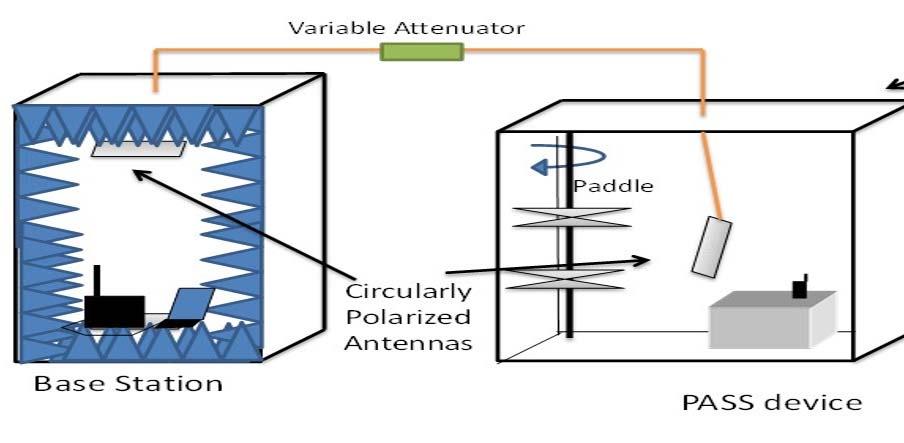
89
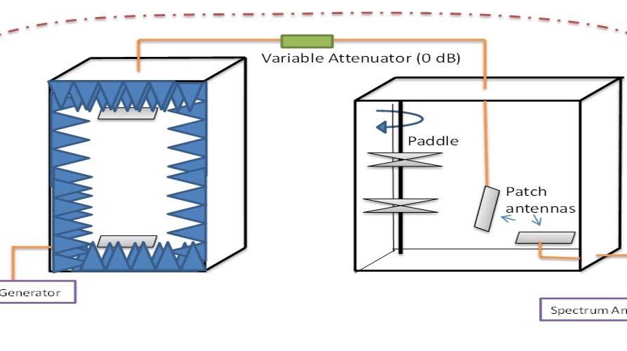
90
91 123 of 210 2/11/2016 1:39 PM Public Input No. 96-NFPA [ Chapter 8 ] Chapter 8 Test Methods 8.1 Sample Preparation Application The sample preparation procedures contained in this section shall apply to each test method in this chapter, as specifically referenced in the sample preparation section of each test method Only the specific sample preparation procedure or procedures referenced in the sample preparation section of each test method shall be applied to that test method Room Temperature Conditioning Procedure Samples shall be conditioned at a temperature of 22 C ± 3 C (72 F ± 5 F) and relative humidity (RH) of 50 percent ± 25 percent for at least 4 hours Samples shall be tested within 5 minutes after removal from conditioning Cold Temperature Conditioning Procedure Specimens shall be exposed to a temperature of -20 C + 0/-3 C (-4 F + 0/-5 F) for at least 4 hours Testing shall begin within 30 seconds of the being removed from the conditioning Elevated Temperature Conditioning Procedure Specimens shall be exposed to a temperature of 71 C + 1/-0 C (160 F + 2/-0 F) for at least 4 hours Testing shall begin within 30 seconds of the being removed from the conditioning. 8.2 Sound Pressure Level Tests Application This test method shall apply to all PASS Modifications to this test method for testing pre-alarm signals shall be as specified in Modifications to this test method for testing alarm signals shall be as specified in Modifications to this test method for testing low power source warning signals shall be as specified in Samples Samples shall be complete PASS.
92 166 of 210 2/11/2016 1:39 PM One or more failing this test shall constitute failing performance Radio System Tests for RF PASS Multi-Hop RF Test Application. The application shall be as specified in Samples. The samples shall be as specified in Specimens Specimens for testing shall be complete RF PASS consisting of one RF PASS device, two repeating devices capable of relaying an RF PASS signal, and a base station designed for use with it, provided by the manufacturer. The repeater device(s) may be an RF PASS One RF PASS, two repeating devices capable of relaying an RF PASS signal, and one base station shall be used in each test. More than one RF PASS may be used if additional devices are being used as repeating devices All multi-hop RF tests shall be conducted using in Table (a) if the are stand-alone or removable integrated PASS and in Table (b) if the are non-removable integrated PASS Test Apparatus The multi-hop RF test shall be conducted as shown in Figure in the following two configurations. (1) With the base station acting as the receiver and the RF PASS under test transmitting an alarm signal (2) With the RF PASS under test acting as a receiver and the base station transmitting an evacuation alarm NOTE: One reverberation chamber and three anechoic chambers provide multi-hop path and shielding between the RF PASS under test and the base station. The chambers are linked by a known amount of attenuation, representing a specified path loss between each hop. FIGURE Apparatus Used for Multi-Hop RF Test For both configurations, the total attenuation (including cables, connectors, free-space path loss, antenna loss, and external added attenuation) between two anechoic chambers shall correspond to 100 db. The total attenuation between the anechoic and reverberation chamber shall correspond to 80 db Anechoic Chambers. The anechoic chambers shall be as specified in Reverberation Chamber. The reverberation chamber shall be as specified in Antennas Circularly polarized antennas shall be used to minimize the dependence of the test on the orientation within the chamber of the RF PASS under test, and base station Five circularly polarized antennas and one linearly polarized horn antenna shall be used during the calibration steps. Five circularly polarized antennas shall be used during the test Cables permanently connected to any antenna shall be no longer than 24 in. (61 cm) to minimize errors in estimating the antennas gain during the calibration step, unless a three-antenna calibration is used to determine the antenna gain, in which case the cable shall be the same as that used during the three-antenna calibration Cables. The cables shall be as specified in Test Equipment. The test equipment shall be as specified in Procedure Procedure for Field Uniformity Calibration in Anechoic Chamber. The procedure for field uniformity calibration shall be as specified in Procedure for Field Calibration in Reverberation Chamber. The procedure for field calibration in the reverberation chamber shall be as specified in Procedure for Configuring one Anechoic Chamber Connected to one Reverberation Chamber with Target Attenuation. This procedure shall be carried out for the connection between an
93 167 of 210 2/11/2016 1:39 PM anechoic chamber and a reverberation chamber, antennas, and cables The chambers shall be configured as shown in Figure Two circularly polarized antennas shall be inserted into the reverberation chamber as shown in Figure One dual ridged horn antenna as shown in Figure shall be inserted into the anechoic chamber on the same table tops where the RF PASS components shall be placed during the attenuation test. The gain of these antennas shall be obtained from the manufacturer s specifications or by use of a technique such as a three-antenna method One calibration antenna shall be connected to the signal generator, and the other to the spectrum analyzer through bulkhead adapters in the body of the test chambers. The cables connecting the antennas to the bulkhead adapters shall be of a length that limits power loss to less than 2 db The power loss in the cables connecting the signal generator and spectrum analyzer to the bulkheads of the chambers shall be determined through measurement The reverberation chamber paddle shall be on and operating at 0.2 revolutions per minute and path loss measurements shall be collected every 3 seconds The path loss measurements shall be averaged. This value shall be regarded as the total path loss between the table top of the anechoic chamber and the reverberation chamber The system path loss shall be measured between the reference plane within the anechoic chamber and the reverberation chamber specified in Figure with the external attenuator set to 0 db. The power loss between the measurement reference planes shall be a positive quantity that is measured and recorded as measured path loss, 0 db. Measurements shall be collected over the frequency of operation of the RF PASS under test. The resolution bandwidth of the spectrum analyzer shall be less than or equal to 1 khz The calibrated path loss, 0 db shall be calculated as measured path loss, 0 db gain of calibration antennas, where gain of calibration antennas is the sum of the specified gain of each calibration antenna in decibels The external attenuator to achieve the total attenuation from table to table shall be calculated as total attenuation calibrated path loss, 0 db, where total attenuation is 80 db between the anechoic chamber and reverberation chamber for the multi-hop RF test. NOTE: Consists of the summation (in db) of the various fixed elements in the propagation path, plus the external attenuators. FIGURE Configuration for Calibration of Target Path Loss between an Anechoic Chamber and a Reverberation Chamber Procedure for Configuring one Reverberation Chamber Connected to one Anechoic Chamber with Target Attenuation. This procedure shall be carried out for the connection between reverberation chamber and anechoic chamber, antennas, and cables The chambers shall be configured as shown in Figure Two circularly polarized antennas shall be inserted into the reverberation chamber as shown in Figure One dual ridged horn antenna as shown in Figure shall be inserted into the anechoic chamber on the same table tops where the RF PASS components shall be placed during the attenuation test. The gain of these antennas shall be obtained from the manufacturer s specifications or by use of a technique such as a three-antenna method One calibration antenna shall be connected to the signal generator, and the other to the spectrum analyzer through bulkhead adapters in the body of the test chambers. The cables connecting the antennas to the bulkhead adapters shall be of a length that limits power loss to less than 2 db The power loss in the cables connecting the signal generator and spectrum analyzer to the bulkheads of the chambers shall be determined through measurement The reverberation chamber paddle shall be on and operating at 0.2 revolutions per minute and path loss measurements shall be collected every 3 seconds The path loss measurements shall be averaged. This value shall be regarded as the total path loss between the reverberation chamber and the table top of the anechoic chamber.
94 168 of 210 2/11/2016 1:39 PM The system path loss shall be measured between the reverberation chamber and the reference plane within the anechoic chamber specified in Figure with the external attenuator set to 0 db. The power loss between the measurement reference planes shall be a positive quantity that is measured and recorded as measured path loss, 0 db. Measurements shall be collected over the frequency of operation of the RF PASS under test. The resolution bandwidth of the spectrum analyzer shall be less than or equal to 1 khz The calibrated path loss, 0 db shall be calculated as measured path loss, 0 db gain of calibration antennas, where gain of calibration antennas is the sum of the specified gain of each calibration antenna in decibels The external attenuator to achieve the total attenuation from table to table shall be calculated as total attenuation calibrated path loss, 0 db, where total attenuation is 80 db between the anechoic chamber and reverberation chamber for the multi-hop RF test. NOTE: Consists of the summation (in db) of the various fixed elements in the propagation path, plus the external attenuators. FIGURE Configuration for Calibration of Target Path Loss between a Reverberation Chamber and an Anechoic Chamber Procedure for Configuring Two Anechoic Chambers with the Target Attenuation. This procedure shall be carried out for the pair of anechoic chambers, antennas, and cables The chambers shall be configured as shown in Figure Two dual ridged horn antennas, as shown in Figure shall be inserted into the anechoic chambers on the same table tops where the RF PASS components shall be placed during the attenuation test. The gain of these antennas shall be obtained from the manufacturer s specifications or by use of a technique such as a three-antenna method One calibration antenna shall be connected to the signal generator, and the other to the spectrum analyzer through bulkhead adapters in the body of the test chambers. The cables connecting the antennas to the bulkhead adapters shall be of a length that limits power loss to less than 2 db The power loss in the cables connecting the signal generator and spectrum analyzer to the bulkheads of the chambers shall be determined through measurement The system path loss shall be measured between the two measurement references planes specified in Figure The power loss between the measurement reference planes shall be a positive quantity that is measured and recorded as measured path loss, 0 db. Measurements shall be collected over the frequency of operation of the RF PASS under test. The resolution bandwidth of the spectrum analyzer shall be less than or equal to 1 khz The calibrated path loss, 0 db shall be calculated as measured path loss, 0 db gain of calibration antennas, where gain of calibration antennas is the sum of the specified gain of each calibration antenna in decibels The external attenuator to achieve the total attenuation from table to table shall be calculated as total attenuation calibrated path loss, 0 db, where total attenuation is 100 db between two anechoic chambers. NOTE: Consists of the summation (in db) of the various fixed elements in the propagation path, plus the external attenuators. FIGURE Configuration for Calibration of Target Path Loss between Two Anechoic Chambers Procedure for Multi-Hop RF Test Alarm Signal Test. The test shall be conducted with the base station acting as the receiver and the RF PASS under test transmitting an alarm signal upon initiation of the alarm signal The total attenuation, including cables, connectors, free-space path loss, antenna loss, and external added attenuation between the two anechoic chambers shall correspond to 100 db. The total attenuation between the reverberation chamber and anechoic chamber shall correspond to 80 db The total attenuation, including cables, connectors, free-space path loss, antenna loss, and
95 169 of 210 2/11/2016 1:39 PM external added attenuation, between the base station and the RF PASS under test shall correspond to 260 db using the calibration procedure specified in The reverberation chamber paddle shall be turned on and shall rotate at 3 ± 2 revolutions per minute A wireless link shall be established between the base station and the RF PASS under test before closing the chambers doors The chambers doors shall be closed for one minute before proceeding The RF PASS with the largest amount of attenuation between it and the base station shall be the device under test. The duration of time between the initiation of the alarm signal until the reception of the alarm signal shall be recorded. This test shall be repeated three times The alarm signal test shall be conducted twice for each of the three trials. (A) The RF PASS system shall be tested with the RF PASS perpendicular to the surface of the tabletop and the base station antenna parallel to the surface of the tabletop. (B) The RF PASS system shall be tested with the RF PASS parallel to the surface of the tabletop and the base station antenna parallel to the surface of the tabletop Evacuation Alarm Test. The test shall be conducted with the RF PASS under test acting as a receiver and the base station transmitting an evacuation alarm The total attenuation, including cables, connectors, free-space path loss, antenna loss, and external added attenuation between the two anechoic chambers shall correspond to 100 db. The total attenuation between the reverberation chamber and anechoic chamber shall correspond to 80 db The total attenuation, including cables, connectors, free-space path loss, antenna loss, and external added attenuation, between the base station and the RF PASS under test shall correspond to 260 db using the calibration procedure specified in The reverberation chamber paddle shall be turned on and shall rotate at 3 ± 2 revolutions per minute A wireless link shall be established between the base station and RF PASS under test before closing the chambers doors An alarm shall be sent from the base station without opening the anechoic doors, using any necessary additional software or method. The alarm shall be sent 1.5 minutes after activating the automated click software The RF PASS under test shall be kept in motion so that the motion-sensing device shall not trigger the alarm signal. A mechanism to move the RF PASS under test shall be permitted to be used. Any mechanism employed to move the RF PASS under test shall not disturb the field uniformity of the chamber more than 3 db as specified in The RF PASS with the highest total attenuation between it and the base station shall be the device under test. The duration of time between the initiation of the evacuation alarm and the reception of the alarm for the RF PASS under test shall be recorded The evacuation alarm test shall be conducted twice. (A) The RF PASS system shall be tested with the RF PASS perpendicular to the surface of the tabletop and the base station antenna parallel to the surface of the tabletop. (B) The RF PASS system shall be tested with the RF PASS parallel to the surface of the tabletop and the base station antenna parallel to the surface of the tabletop Report. The report shall be as specified in Interpretation Pass or fail performance shall be determined for each specimen. A signal which is not received from either test within 30 seconds shall constitute failing performance One or more failing this test shall constitute failing performance Additional Proposed Changes File Name Description Approved Figure_ jpg FIGURE Apparatus Used for Multi-Hop RF Test.
96 170 of 210 2/11/2016 1:39 PM Figure_ jpg Figure_ jpg Figure_ jpg FIGURE Configuration for Calibration of Target Path Loss between an Anechoic Chamber and a Reverberation Chamber. FIGURE Configuration for Calibration of Target Path Loss between a Reverberation Chamber and an Anechoic Chamber. FIGURE Configuration for Calibration of Target Path Loss between Two Anechoic Chambers. This text supports the introduction of new test methods for multi-hop operation. Currently, no standardized methods exist to test the operation of RF-based PASS systems that utilize repeaters. The rationale for developing the Multi-Hop test method is to fill this gap. Submitter Full Name: Kate Remley Organization: National Institute of Standards and Technology Affilliation: NFPA ESE Committee's Ad Hoc Committee on RF PASS Submittal Date: Wed Jan 06 13:37:11 EST 2016
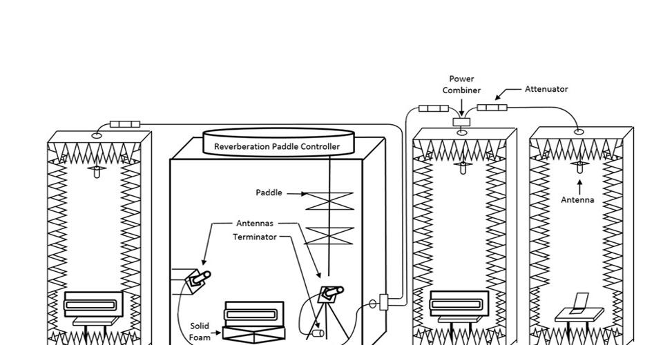
97

98
99
100
101 171 of 210 2/11/2016 1:39 PM Public Input No. 73-NFPA [ Section No ] The audio test mannequin shall have the sound level meter microphone mounted at the left ear, as shown in Figure Figure Audio Test Mannequin. Changing PASS Pre Alarm and PASS Low Battery warning SPL measurements to be made in the same was as the PASS Alarm measurement (1 m spherical distance from the annunciator) would eliminate the need to show where the sound meter microphone should be positioned. Tests that involve placing the microphone around the ear are not repeatable or reproducible due to the acoustics of the room, where the mic is inserted into the ear, the position of the body of the person holding the meter, etc. Moving to the test we have specified for the PASS should prove to be more repeatable. Submitter Full Name: CRAIG GESTLER Organization: MSA Safety Affilliation: MSA Safety Submittal Date: Wed Dec 23 10:47:49 EST 2015
102 172 of 210 2/11/2016 1:39 PM Public Input No. 74-NFPA [ New Section after ] TITLE OF NEW CONTENT The sound level meter shall meet the requirements of ANSI S1.4 Type 1. There were no requirements for the sound meter used for the tests. Submitter Full Name: CRAIG GESTLER Organization: MSA Safety Affilliation: PASS Alarm TG Submittal Date: Wed Dec 23 10:53:55 EST 2015
103 173 of 210 2/11/2016 1:39 PM Public Input No. 75-NFPA [ Section No ] All sound pressure level measurements shall be made with the sound level meter ballistics set to the peak response setting. A weighing with a Fast response time. The max-hold function (if available) may be used to hold the maximum value observed by the meter for the specified period of time. Revised measurement method for the PASS Alarm, PASS Pre Alarm and PASS low battery warning alarms. This method has proven to correlate with the subjective evaluation of the proposed 2018 PASS alarm. The sound pressure level is integrated over a short period of time rather than just an instantaneous peak. Submitter Full Name: CRAIG GESTLER Organization: MSA Safety Affilliation: PASS Alarm TG Submittal Date: Wed Dec 23 10:56:03 EST 2015
104 174 of 210 2/11/2016 1:39 PM Public Input No. 76-NFPA [ New Section after ] TITLE OF NEW CONTENT The specimen shall be mounted on the audio test mannequin in the preferred mounting position and orientation for optimal performance as specified by the manufacturer. There is no direction regarding how the PASS is to be supported/held/mounted for the PASS alarm SPL test. This proposal mounts the SCBA/PASS on the same mannequin used for the PASS Pre Alarm and PASS Low battery alarm tests. Submitter Full Name: CRAIG GESTLER Organization: MSA Safety Affilliation: MSA Safety Submittal Date: Wed Dec 23 11:06:43 EST 2015
105 175 of 210 2/11/2016 1:39 PM Public Input No. 77-NFPA [ Section No ] The sound pressure level for the alarm signal shall be measured in a spherical radius at a distance of 3 m of 1 m 2.5 /-0 m 0 cm (9 3.9 ft + 3 ft /-0 ft) in from the specimen's annunciator. Reducing the SPL measurement sphere from 3m to 1m should help to eliminate some of the variability in the measurements by making the distance from the PASS to the mic significantly smaller than the dimensions of the room. Constructive and destructive wave interference should also be lessened. The SPL targets for all the tests have been adjusted in other comments to take the reduced distance into account. Submitter Full Name: CRAIG GESTLER Organization: MSA Safety Affilliation: MSA Safety Submittal Date: Wed Dec 23 11:11:16 EST 2015
106 176 of 210 2/11/2016 1:39 PM Public Input No. 78-NFPA [ Section No ] The sound pressure level for the alarm signal shall be measured for 60 minutes +5/-0 minutes. 1 minute ( /- 5 seconds), 59 minutes ( 1/-0 minutes) after the start of the test. Five measurements, each a minimum of 6 seconds, shall be taken in the 1 minute period. The maximum sound pressure value shall be recorded for each measurement. The lowest of the five measurements shall be discarded and the remaining four shall be the sound pressure values. We only care about SPL at the end of the test (the last minute) when the batteries are at their lowest point. It does not make sense (nor is it practical) to measure the SPL over the entire one hour period. The measurement method has been revised to be a series of measurements, taken in the last minute, according to the new method described in (comment #75). One of the measurements is discarded in case there is an error in taking the measurement. The process to deplete the batteries and then wait 59 minutes to take the readings is long and tedious. Throwing out one reading will prevent one reading taken in error from ruining the entire test. Submitter Full Name: CRAIG GESTLER Organization: MSA Safety Affilliation: MSA Safety Submittal Date: Wed Dec 23 11:16:03 EST 2015
107 177 of 210 2/11/2016 1:39 PM Public Input No. 79-NFPA [ Section No ] The alarm signal sound pressure level shall sound pressure values for the PASS alarm signal shall be recorded, evaluated, and reported for the entire duration to determine pass or fail performance. Updating the wording to reflect the one minute measurement time as opposed to the "entire duration" that was suggested. Submitter Full Name: CRAIG GESTLER Organization: MSA Safety Affilliation: MSA Safety Submittal Date: Wed Dec 23 13:03:24 EST 2015
108 178 of 210 2/11/2016 1:39 PM Public Input No. 80-NFPA [ Section No ] The sound pressure level for the pre-alarm signal shall be measured at the left ear of the mannequin in a spherical radius at a distance of 1m 2.5cm from the specimen't annunciator for the duration of the pre-alarm. Changing the test method for the PASS Pre alarm to match the test method for the PASS full alarm. Submitter Full Name: CRAIG GESTLER Organization: MSA Safety Affilliation: MSA Safety Submittal Date: Wed Dec 23 13:07:30 EST 2015
109 179 of 210 2/11/2016 1:39 PM Public Input No. 81-NFPA [ Section No ] The sound pressure level for the low power source warning signal shall be measured at the left ear of the mannequin for 60 minutes +5/-0 minutes. in a spherical radius at a distance of 1m 2.5cm from the specimen s annunciator for 1 minute ( /- 5 seconds), 59 minutes ( 1/-0 minutes) after the start of the test. Five measurements, each a minimum of 6 seconds, shall be taken in the 1 minute period. The maximum sound pressure value shall be recorded for each measurement. The lowest of the five measurements shall be discarded and the remaining four shall be the sound pressure values. Modifying the test to measure the PASS Low battery warning alarm to use the same procedure as used for the PASS Alarm. This method is only measuring the SPL in the last minute of the 60 minute test (where the batteries will be at their lowest). The distance has also been reduced to 1m to help minimize test variability. Submitter Full Name: CRAIG GESTLER Organization: MSA Safety Affilliation: MSA Safety Submittal Date: Wed Dec 23 13:09:56 EST 2015
110 180 of 210 2/11/2016 1:39 PM Public Input No. 82-NFPA [ Section No ] The specimen shall remain motionless and be allowed to cycle from sensing mode to alarm mode. When the PASS cycles into the alarm mode, within 30 seconds the sound pressure level pressure value for the alarm signal shall be measured in a spherical radius at a distance of 3 m +1 of 1 m 2.5 /-0 m 0 cm (9.9 ft ft 1.1 /-0 ft) from the specimen s annunciator. Changing the measurement method to be the same as that used for the other PASS alarm measurements (at 1m instead of 3m). This will help to reduce measurement variability. Submitter Full Name: CRAIG GESTLER Organization: MSA Safety Affilliation: MSA Safety Submittal Date: Wed Dec 23 13:17:09 EST 2015
111 181 of 210 2/11/2016 1:39 PM Public Input No. 24-NFPA [ Section No ] A sampling digital oscilloscope connected to a microphone shall be used to measure the frequencies of the alarm signal. Section refers to the alarm signal which is not covered in section Section indicates that this test applies to the pre-alarm signal. Measurement equipment for the pre-alarm signal is already specified previously. Submitter Full Name: James Rose Organization: Safety Equipment Institute Submittal Date: Thu Jul 16 22:48:14 EDT 2015
112 182 of 210 2/11/2016 1:39 PM Public Input No. 25-NFPA [ Section No ] The pre-alarm or alarm signal shall be activated, and the signal frequency shall be measured. A portion of section refers to the alarm signal which is not covered in section Section indicates that this test applies to the pre -alarm signal. Submitter Full Name: James Rose Organization: Safety Equipment Institute Submittal Date: Thu Jul 16 22:51:18 EDT 2015
113 183 of 210 2/11/2016 1:39 PM Public Input No. 26-NFPA [ Section No ] The alarm signal shall be recorded at a minimum of 5 mega-samples/second, verified that it meets the requirements of , and reported. Section refers to the alarm signal which is not covered in section Section indicates that this test applies to the pre-alarm signal. Submitter Full Name: James Rose Organization: Safety Equipment Institute Submittal Date: Thu Jul 16 22:53:37 EDT 2015
114 184 of 210 2/11/2016 1:39 PM Public Input No. 27-NFPA [ Section No ] Pass or fail performance shall be determined for each specimen for both the pre-alarm and the alarm signals. signal, verified that it meets the requirements of , and reported. A portion of Section refers to the alarm signal, which is not covered in Section Section indicates that this test applies to the pre-alarm signal. Submitter Full Name: James Rose Organization: Safety Equipment Institute Submittal Date: Thu Jul 16 22:55:44 EDT 2015
115 185 of 210 2/11/2016 1:39 PM Public Input No. 83-NFPA [ Section No ] All sound pressure level measurements shall be made with the sound level meter ballistics set to the peak response setting, and the A weighing with a Fast response time. The maximum hold function (if available) may be used to hold the maxim value observed by the meter for the specified period of time. The test subject shall don the following: (1) The protective ensemble specified in (2) The specimen PASS per the manufacturers instructions Changing the way that the PASS alarm is measured during the Signal Muffle Test to match the other PASS alarm signal tests. Submitter Full Name: CRAIG GESTLER Organization: MSA Safety Affilliation: MSA Safety Submittal Date: Wed Dec 23 13:21:12 EST 2015
116 186 of 210 2/11/2016 1:39 PM Public Input No. 84-NFPA [ Section No ] The sound pressure level pressure value for the alarm signal shall be measured in a spherical radius at a distance of 3 m +1 of 1 m 0.33 /-0 m (9.9 ft ft 1.1 /-0 ft) in from the waist of the test subject. Changing the measurement process to match that of the other PASS alarm tests. Submitter Full Name: CRAIG GESTLER Organization: MSA Safety Affilliation: MSA Safety Submittal Date: Wed Dec 23 13:30:02 EST 2015
117 187 of 210 2/11/2016 1:39 PM Public Input No. 85-NFPA [ Section No ] The point-to-point RF attenuation test shall be conducted as shown in Figure in the following two configurations: (1) With the base station acting as the receiver and the RF PASS transmitting an alarm signal (2) With the RF PASS acting as a receiver and the base station transmitting an evacuation alarm Figure Apparatus Used for Point-to-Point RF Attenuation Test. Two anechoic chambers provide shielding between the RF PASS and the base station. The chambers are linked by a known amount of attenuation, representing a specified path loss. Additional Proposed Changes File Name Figure_ jpg Description Approved Correction of "SCBU" to "SCBA" in Figure Submitter Full Name: Kate Remley Organization: National Institute of Standards and Technology Submittal Date: Tue Jan 05 11:01:15 EST 2016
118
119 188 of 210 2/11/2016 1:39 PM Public Input No. 98-NFPA [ Section No ] For both configurations, the total attenuation (including cables, connectors, free-space path loss, antenna loss, and external added attenuation) between the base station and the RF PASS shall correspond to 100 db ± 3dB 3 db. The total attenuation shall be calculated using the methods described in Insert space between value and unit in 3 db. Submitter Full Name: Kate Remley Organization: National Institute of Standards and Technology Submittal Date: Wed Jan 06 15:41:26 EST 2016
120 189 of 210 2/11/2016 1:39 PM Public Input No. 47-NFPA [ Section No ] Overall usable interior height of an anechocic anechoic chamber shall be no less than 40 in. (102 cm) between the antenna and tabletop or 55 in. (140 cm) total. 1.0 m = 3 wavelengths at 900 MHz. These specifications shall not preclude the use of a larger anechoic chamber, including one large enough to contain operation personnel if the RF isolation conditions in and field uniformity conditions in are satisfied. Typo. Should be anechoic. Submitter Full Name: Kate Remley Organization: National Institute of Standards and Technology Submittal Date: Thu Nov 05 17:58:46 EST 2015
121 190 of 210 2/11/2016 1:39 PM Public Input No. 48-NFPA [ Section No ] Overall usable interior height of an anechocic chamber shall be no less than 40 in. (102 cm) between the antenna and tabletop or 55 in. (140 cm) total. 1.0 m = 3 wavelengths at 900 MHz. These specifications shall not preclude the use of a larger anechoic chamber, including one large enough to contain operation personnel if the RF isolation conditions in and field uniformity conditions in are satisfied. In the last sentence field uniformity conditions in should read field uniformity conditions in ROC , Log #13 (p. 21) specifies the incorrect section number (it was originally ). Submitter Full Name: Kate Remley Organization: National Institute of Standards and Technology Submittal Date: Thu Nov 05 18:00:18 EST 2015
122 191 of 210 2/11/2016 1:39 PM Public Input No. 49-NFPA [ Section No ] Each chamber shall include an antenna mount. Section is essentially repeated in Section Section should be deleted. Submitter Full Name: Kate Remley Organization: National Institute of Standards and Technology Submittal Date: Thu Nov 05 18:02:46 EST 2015
123 192 of 210 2/11/2016 1:39 PM Public Input No. 50-NFPA [ Section No ] Each chamber shall include a nonconducting antenna mount that shall ensure the usable interior height specified in Incorrect section is specified should be Submitter Full Name: Kate Remley Organization: National Institute of Standards and Technology Submittal Date: Thu Nov 05 18:04:50 EST 2015
124 193 of 210 2/11/2016 1:39 PM Public Input No. 97-NFPA [ Section No ] Procedure for Field Uniformity Calibration Each anechoic chamber shall be calibrated individually, using the same antenna and interior coaxial cables that shall be used in during the RF PASS test. The configuration shall be as shown in Figure Figure Configuration for Testing the Electric Field Uniformity Using a Signal Generator and a Three-Axis Electric Field Probe The antenna used for the point-to-point attenuation RF PASS test shall be mounted to the antenna mount specified in A coaxial cable shall connect the antenna to the interior bulkhead adapter of the chamber A coaxial cable shall connect the exterior side of the bulkhead adapter of the chamber to a signal generator. The signal generator shall be set to the frequency of operation of the RF PASS. The power level setting shall provide a reading on the field probe The field probe shall be connected to its receiver through a chamber bulkhead.
125 The total electric field shall be sequentially measured and recorded at the points specified in Figure Figure The Measurement Pattern for Checking the Electric Field Uniformity on the Table Surface * Contour lines of equal power levels, determined from the measured electric field results, E x, E y, and E z, shall be plotted. These power levels shall be plotted The power level at each of the 25 points shall be calculated relative to the minimum total power measured at one of the points. The minimum total power, P, shall be determined by calculating the total power at each of the measurement points, and then selecting the minimum value of those calculations as follows: where: i = 1, 2, (the measured points), k = x, y, z, or total, and The variation in the total power over the center 30 cm 30 cm portion of the surface shall not exceed 3 db of variation in the received signal strength over the center 30 cm 30 cm of the surface 75% of the measured points in shall not exceed the minimum measured total power results by more than 3 db. Additional Proposed Changes File Name Description Approved Figure_ jpg Figure_ jpg FIGURE Configuration for Testing the Electric Field Uniformity Using a Signal Generator and a Three-Axis Electric Field Probe. FIGURE The Measurement Pattern for Checking The Electric Field Uniformity on the Table Surface. This text supports the introduction of new test methods for multi-hop operation. Updating the field uniformity test in the Point-to-Point Attenuation Test as proposed will allow the same field uniformity test to be used for the existing test methods and for the new Multi-Hop Test. This will save time for the test labs without increasing uncertainty. Currently, no standardized methods exist to test the operation of RF-based PASS systems that utilize repeaters. 194 of 210 2/11/2016 1:39 PM
126 195 of 210 2/11/2016 1:39 PM The rationale for developing the Multi-Hop test method is to fill this gap. Submitter Full Name: Kate Remley Organization: National Institute of Standards and Technology Affilliation: NFPA ESE Committee's Ad Hoc Committee on RF PASS Submittal Date: Wed Jan 06 14:48:49 EST 2016

127
128
129 196 of 210 2/11/2016 1:39 PM Public Input No. 4-NFPA [ Section No ] The RF PASS shall be tested in conjunction with the model of base station with which it is intended to be deployed. If a portable computer is utilized in the base station, radio system tests shall be conducted using the manufacturer's supplied portable computer. The portable computer, if used, The radiating element of the base station (i.e., the antenna) shall be placed into the test chamber with. If the base station is placed outside the test chamber, a coaxial cable shall connect the antenna to the base station through either a bulkhead connector or through the bulkhead pass-through. If the base station is place inside the test chamber, the base station shall connect to the host computer using a data cable via the bulhead pass-through. Conducting these tests as currently written is difficult. Testing with the PC outside of the chamber should be permissible because the isolation requirements for both the chambers and the interconnection coaxial cables are >100dB, which is the same number for the link budget tests. In addition, the base station (and associated computer) are assumed to pass FCC regulations, which implies that any high-power emission is limited to the radiating element (i.e., the antenna),of the base station. Therefore, any signal emanating from the base station has already been attenuated to FCC Part 15 levels, far below the 1W allowed at the antenna. Also, these FCC tests were conducted with the appropriate cables connected to the base station, which ensures that the long range radio signal is not received by any peripheral cables and re-radiated into the environment. Submitter Full Name: Craig Gestler Organization: MSA Safety Affilliation: MSA Safety Submittal Date: Thu Jul 02 15:02:38 EDT 2015
130 197 of 210 2/11/2016 1:39 PM Public Input No. 7-NFPA [ Section No ] Upon closing the second door, the duration until the loss-of-signal alarm sounds from each of the RF PASS and the base station shall be noted. Firefighters advised that having an audible alarm for out of range would be a distraction from the other "more urgent" alarms, and hence requested to change the working to indicate a visual alarm only for out of range. There was discussion about an optional audible out of range alarm that could be muted, but that was also struck as indicated by log #20 ( Log #20 FAE-ELS) The log was accepted in principal and implemented for and (the audible requirement was removed). The reference to the audible alarm should have also been removed from the definition in (another comment) and (but is was not removed) (another comment) Submitter Full Name: Craig Gestler Organization: MSA Safety Affilliation: MSA Safety Submittal Date: Thu Jul 02 15:43:07 EDT 2015
131 198 of 210 2/11/2016 1:39 PM Public Input No. 86-NFPA [ Section No ] The RF interference test shall be conducted with apparatus that meets the guidelines in through , as illustrated in Figure Figure Apparatus Used for RF Interference Test. Two anechoic chambers provide shielding between the RF PASS and the base station. The chambers are linked by a known amount of attenuation, representing a specified path loss. An interfering RF signal is introduced into the test chambers by use of a power combiner. Additional Proposed Changes File Name Figure_ jpg Description Approved Correction of "SCBU" to "SCBA". Submitter Full Name: Kate Remley Organization: National Institute of Standards and Technology Submittal Date: Tue Jan 05 11:07:35 EST 2016
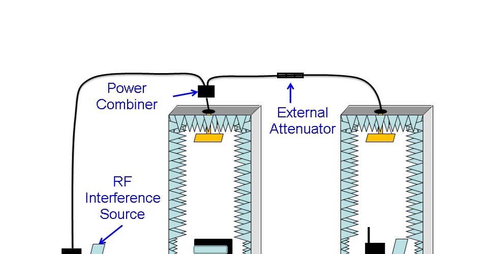
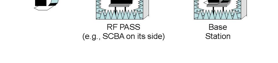
132
133 199 of 210 2/11/2016 1:39 PM Public Input No. 51-NFPA [ Section No ] Power Combiner. A power combiner shall be used to combine the signal from the base station with the interfering signal, as shown in Figure The power combiner shall have two input ports and one output port, shall use Type N or SMA connectors, and shall have a minimum isolation between the input ports of 20 db. The power combiner can also have SMA connectors. Submitter Full Name: Kate Remley Organization: National Institute of Standards and Technology Submittal Date: Thu Nov 05 18:08:46 EST 2015
![200 of 210 2/11/2016 1:39 PM Public Input No. 94-NFPA 1982-2016 [ Section No. 8.21.4.4.1 ] 8.21.4.4.1 The 900 MHz interferer shall be a programmable signal generator or a wireless development board controlled by a computer as illustrated in Figure 8.](/docs-images/82/86086722/images/134-0.jpg "21.4.4.1. The interferer shall be capable of producing the equivalent channel usage requirements in Table 8.21.4.4. The interferer shall hop over 51 channels in the 902 MHz to 928 MHz band, at a hop duration of 40 ms ± 2 ms.")
134 200 of 210 2/11/2016 1:39 PM Public Input No. 94-NFPA [ Section No ] The 900 MHz interferer shall be a programmable signal generator or a wireless development board controlled by a computer as illustrated in Figure The interferer shall be capable of producing the equivalent channel usage requirements in Table The interferer shall hop over 51 channels in the 902 MHz to 928 MHz band, at a hop duration of 40 ms ± 2 ms. The interferer shall utilize an RF data rate of 38 kb/sec ± 2 kb/sec and a serial data rate of 38 kb/sec ± 2 kb/sec. Data are transmitted with filtered non-return-to-zero (NRZ) encoding modulated onto a carrier with binary frequency shift keying (FSK). Figure Apparatus Used for Creating the 900 MHz and 2.46 GHz Band Interference. Additional Proposed Changes File Name Description Approved Figure_ jpg Figure Correct "SCBU" to read "SCBA" Submitter Full Name: Kate Remley Organization: National Institute of Standards and Technology Submittal Date: Wed Jan 06 10:21:03 EST 2016
135
136 201 of 210 2/11/2016 1:39 PM Public Input No. 28-NFPA [ Section No ] The physical distance between the transmit antenna and the center of the testing platform supporting the SCBA PASS shall be 1.25 m ± 0.1 m. Currently, Section references a distance between an antenna and a platform supporting an SCBA, which covers PASS which is integrated with an SCBA. However, since this standard also covers stand alone PASS, the wording in Section also needs to anticipate testing stand alone PASS. As a result, the word "SCBA" should be revised to "PASS". Submitter Full Name: James Rose Organization: Safety Equipment Institute Submittal Date: Thu Jul 16 22:59:17 EDT 2015
137 202 of 210 2/11/2016 1:39 PM Public Input No. 52-NFPA [ Section No ] The interference signal path loss in db shall be calculated as cable losses + power combiner insertion losses + external attenuator losses - interference signal amplification - antenna gain in the test chamber. The value shall be 0 ± 2 db, the interference shall be either attenuated or amplified so that the calculated value equals 0 ± 2 db. Language was not transcribed properly. Section should read: The interference signal path loss in db shall be calculated as cable losses + power combiner insertion losses + external attenuator losses interference signal amplification antenna gain in the test chamber. Note that the minus sign is missing in the second half of the sentence. Submitter Full Name: Kate Remley Organization: National Institute of Standards and Technology Submittal Date: Thu Nov 05 18:11:18 EST 2015
138 203 of 210 2/11/2016 1:39 PM Public Input No. 103-NFPA [ New Section after A ] A It is often desired by end users and owners of PASS and RF-PASS certified to earlier editions of this standard to receive updated parts, components and software that have been certified to the latest edition of this standard. To allow this in an open manner and to optimize the approval application process, this clause has been added such that the latest revision of the standard can used for the certification of the new parts to certify their use on earlier edition PASS devices. Example: New firmware for sound to be installed into the processor of earlier PASS devices so that they can be updated accordingly. For this to occur, the latest edition of the standard is to be used for the testing and modification to the previous certification. Annex material included in the document for proposed changes. Related Public Inputs for This Document Related Input Public Input No. 99-NFPA [Section No ] Relationship Annex material Submitter Full Name: Simon Hogg Organization: Draeger Safety UK Ltd. Submittal Date: Wed Jan 06 16:37:56 EST 2016
139 204 of 210 2/11/2016 1:39 PM Public Input No. 87-NFPA [ Section No. B.3 ] B.3 Measurement System Set-Up. Figure B.3 shows a typical point-to-point RF attenuation test set-up. Two anechoic chambers provide shielding between the portable unit and the base station. The total path loss (or gain) associated with the environmental elements marked in Figure B.3 simulates the path loss experienced by personnel carrying RF PASS within a building or structure when the base station is located outside. The value of the external attenuator is adjusted in a calibration step described below to match the target attenuation. The chambers are shielded so that the RF PASS and base station are isolated from each other. This allows testing of RF attenuation alone. RF interference should be tested in a separate test method. The anechoic material in the chamber simulates a reflection-free environment. Multipath reflections should be tested with a separate test method. Figure B.3 Test Set-Up and Sources of Path Loss (and Gain) in the Point-to-Point RF Attenuation Test. Antennas are mounted in the top of each chamber to receive the signal emitted by the device under test and couple it to the exterior of the chamber. The total system attenuation includes the gain (if any) in these antennas, the free space path loss between the PASS or base station and these antennas, the cables connecting the chambers, and external attenuators that are added to achieve the desired amount of path loss. The point-to-point test method requires that the RF PASS system is able to send and receive alarms when the sum of these components of attenuation corresponds to that specified in the standard. Additional Proposed Changes File Name Figure_B.3.jpg Description Approved Correction of "SCBU" to "SCBA". Submitter Full Name: Kate Remley Organization: National Institute of Standards and Technology Submittal Date: Tue Jan 05 11:10:05 EST 2016
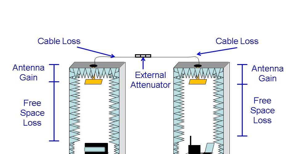

140
Public Input No. 99-NFPA [ Section No ] Statement of Problem and Substantiation for Public Input
![Public Input No. 99-NFPA [ Section No ] Statement of Problem and Substantiation for Public Input](/thumbs/86/93336578.jpg "Public Input No. 99-NFPA [ Section No ] Statement of Problem and Substantiation for Public Input") 1 of 218 5/20/2016 12:24 PM Public Input No. 99-NFPA 1982-2016 [ Section No. 1.1.3 ] 1.1.3 This standard shall not specify requirements for any manufactured to previous editions of this standard To enable
1 of 218 5/20/2016 12:24 PM Public Input No. 99-NFPA 1982-2016 [ Section No. 1.1.3 ] 1.1.3 This standard shall not specify requirements for any manufactured to previous editions of this standard To enable
NFPA TECHNICAL COMMITTEE ON ELECTRONIC SAFETY EQUIPMENT. March 10-12, 2016 Dallas, TX AGENDA
 Tuesday, March 10, 2016 NFPA TECHNICAL COMMITTEE ON ELECTRONIC SAFETY EQUIPMENT March 10-12, 2016 Dallas, TX AGENDA 1. 9:00 a.m. Call to Order - Chairman Bob Athanas 2. Introduction of Members and Guests
TECHNICAL COMMITTEE ON ELECTRONIC SAFETY EQUIPMENT. December 10-12, 2013 San Diego, CA AGENDA
 TECHNICAL COMMITTEE ON ELECTRONIC SAFETY EQUIPMENT December 10-12, 2013 San Diego, CA AGENDA Tuesday, December 10, 2013 1. 9:00 a.m. Call to Order - Chairman Bob Athanas 2. Introduction of Members and
NFPA TECHNICAL COMMITTEE ON ELECTRONIC SAFETY EQUIPMENT. March 18-19, 2014 Fort Lauderdale, FL AGENDA
 NFPA TECHNICAL COMMITTEE ON ELECTRONIC SAFETY EQUIPMENT March 18-19, 2014 Fort Lauderdale, FL AGENDA Tuesday, March 18, 2014 1. 8:00 a.m. Call to Order - Chairman Bob Athanas 2. Introduction of Members
TECHNICAL COMMITTEE ON ELECTRONIC SAFETY EQUIPMENT. Wyndham San Diego Bayside 1335 N. Harbor Drive San Diego, CA NFPA 1982 Second Draft Meeting
 TECHNICAL COMMITTEE ON ELECTRONIC SAFETY EQUIPMENT Wyndham San Diego Bayside 1335 N. Harbor Drive San Diego, CA 92101 NFPA 1982 Second Draft Meeting December 6-8, 2016 AGENDA Meeting Start Time - 9:00
MEETING OF THE TECHNICAL COMMITTEE ON RESPIRATORY PROTECTION EQUIPMENT. NFPA 1981 First Draft Meeting. March 7-9, 2016.
 MEETING OF THE TECHNICAL COMMITTEE ON RESPIRATORY PROTECTION EQUIPMENT NFPA 1981 First Draft Meeting March 7-9, 2016 Dallas, TX AGENDA Monday, March 7, 2016, Start Time 9:00 a.m. 1. Self-introduction of
TECHNICAL COMMITTEE ON SAFETY AT MOTORSPORTS VENUES. NFPA 610 First Draft Meeting. October 17-18, 2016
 TECHNICAL COMMITTEE ON SAFETY AT MOTORSPORTS VENUES NFPA 610 First Draft Meeting October 17-18, 2016 Westin Kansas City at Crown Center 1 East Pershing Road Kansas City, MO, 64108 Conference Call Access:
Adobe Connect - Invitation to NFPA 385 Second Draft Web Conference
 Matthews, Diane Subject: Location: Start: End: Show Time As: Recurrence: Meeting Status: Organizer: Required Attendees: Adobe Connect - Invitation to NFPA 385 Second Draft Web Conference http://nfpa.adobeconnect.com/rpbmeet/
MINUTES OF THE MEETING TECHNICAL COMMITTEE ON RESPIRATORY PROTECTION EQUIPMENT JULY 2015 SACRAMENTO, CA
 MINUTES OF THE MEETING TECHNICAL COMMITTEE ON RESPIRATORY PROTECTION EQUIPMENT 24 25 JULY 2015 SACRAMENTO, CA AGENDA ITEM 1; SELF-INTRODUCTION OF MEMBERS AND GUESTS Chairman Rossos called the Committee
NFPA TECHNICAL COMMITTEE ON ELECTRONIC SAFETY EQUIPMENT. July 21-23, 2015 Sacramento, CA AGENDA
 Tuesday, July 21, 2015 NFPA TECHNICAL COMMITTEE ON ELECTRONIC SAFETY EQUIPMENT July 21-23, 2015 Sacramento, CA AGENDA 1. 9:00 a.m. Call to Order - Chairman Bob Athanas 2. Introduction of Members and Guests
MEETING OF THE TECHNICAL COMMITTEE ON RESPIRATORY PROTECTION EQUIPMENT. NFPA 1989, 1852 First Draft Meeting. August 9-10, 2016.
 MEETING OF THE TECHNICAL COMMITTEE ON RESPIRATORY PROTECTION EQUIPMENT NFPA 1989, 1852 First Draft Meeting August 9-10, 2016 Quincy, MA AGENDA Tuesday, August 9, 2016, Start Time 9:00 a.m. 1. Self-introduction
12/21/2015 National Fire Protection Association Report
 http://submittals.nfpa.org/terraviewweb/viewerpage.jsp?id=232 2012.ditamap&toc=false&draft=true 1/9 Public Comment No. 1 NFPA 232 2015 [ Chapter 2 ] Chapter 2 Referenced Publications 2.1 General. The documents
Page 1 of 6 10/19/2016 9:49 AM. Public Input No. 4-NFPA [ Section No ] Statement of Problem and Substantiation for Public Input
![Page 1 of 6 10/19/2016 9:49 AM. Public Input No. 4-NFPA [ Section No ] Statement of Problem and Substantiation for Public Input](/thumbs/84/89680532.jpg "Page 1 of 6 10/19/2016 9:49 AM. Public Input No. 4-NFPA [ Section No ] Statement of Problem and Substantiation for Public Input") Public Input No. 4-NFPA 111-2016 [ Section No. 1.1.4.1 ] 1.1.4.1 * This standard shall not cover the following: (1) Application of the SEPSS (2) Distribution wiring (3) Systems having total outputs less
Public Input No. 4-NFPA 111-2016 [ Section No. 1.1.4.1 ] 1.1.4.1 * This standard shall not cover the following: (1) Application of the SEPSS (2) Distribution wiring (3) Systems having total outputs less
Technical Committee on Record Protection (REA-AAA)
") Technical Committee on Record Protection (REA-AAA) DATE: September 8, 2015 TO: FROM: M E M O R A N D U M Principal and Alternate Members of the Technical Committee on Record Protection (REA-AAA) Audrey
Technical Committee on Record Protection (REA-AAA) DATE: September 8, 2015 TO: FROM: M E M O R A N D U M Principal and Alternate Members of the Technical Committee on Record Protection (REA-AAA) Audrey
Public Input No. 53-NFPA [ Section No ] Statement of Problem and Substantiation for Public Input. Submitter Information Verification
![Public Input No. 53-NFPA [ Section No ] Statement of Problem and Substantiation for Public Input. Submitter Information Verification](/thumbs/78/78160559.jpg "Public Input No. 53-NFPA [ Section No ] Statement of Problem and Substantiation for Public Input. Submitter Information Verification") of 96 9/25/2015 3:03 PM Public Input No. 53-NFPA 1801-2015 [ Section No. 1.3.5 ] 1.3.5 This standard shall not apply to criteria for the use of thermal imagers by the fire service, the requirements for
of 96 9/25/2015 3:03 PM Public Input No. 53-NFPA 1801-2015 [ Section No. 1.3.5 ] 1.3.5 This standard shall not apply to criteria for the use of thermal imagers by the fire service, the requirements for
NFPA Electronic Safety Equipment Standards What s happening now!
 Precision Indoor Personnel Location and Tracking for Emergency Responders Technology Workshop August 4-5, 2008 Worcester Polytechnic Institute, Worcester, MA NFPA Electronic Safety Equipment Standards
M E M O R A N D U M. Technical Committee on Special Operations Protective Clothing and Equipment
 National Fire Protection Association 1 Batterymarch Park, Quincy, MA 02169-7471 Phone: 617-770-3000 Fax: 617-770-0700 www.nfpa.org M E M O R A N D U M TO: FROM: Technical Committee on Special Operations
Second Revision No. 3-NFPA [ Section No. 2.3 ]
![Second Revision No. 3-NFPA [ Section No. 2.3 ]](/thumbs/96/127511130.jpg "Second Revision No. 3-NFPA [ Section No. 2.3 ]") Second Revision No. 3-NFPA 804-2014 [ Section No. 2.3 ] 2.3 Other Publications. 2.3.1 ASME Publications. American Society of Mechanical Engineers, Three Park Avenue, New York, NY 10016-5990. ASME Boiler
Second Revision No. 3-NFPA 804-2014 [ Section No. 2.3 ] 2.3 Other Publications. 2.3.1 ASME Publications. American Society of Mechanical Engineers, Three Park Avenue, New York, NY 10016-5990. ASME Boiler
Public Input No. 1-NFPA 90B-2015 [ Chapter 2 ]
![Public Input No. 1-NFPA 90B-2015 [ Chapter 2 ]](/thumbs/74/71051808.jpg "Public Input No. 1-NFPA 90B-2015 [ Chapter 2 ]") Public Input No. 1-NFPA 90B-2015 [ Chapter 2 ] Chapter 2 Referenced Publications 2.1 General. The documents or portions thereof listed in this chapter are referenced within this standard and shall be considered
Public Input No. 1-NFPA 90B-2015 [ Chapter 2 ] Chapter 2 Referenced Publications 2.1 General. The documents or portions thereof listed in this chapter are referenced within this standard and shall be considered
IAFF DIVISION OF OCCUPATIONAL HEALTH, SAFETY AND MEDICINE
 IAFF DIVISION OF OCCUPATIONAL HEALTH, SAFETY AND MEDICINE Position on the U.S. Army Soldier & Biological Chemical Command s (SBCCOM), Withdrawn 3/30 Rule and the New Guide: The Risk Assessment of Using
Second Revision No. 1 NFPA [ Chapter 2 ]
![Second Revision No. 1 NFPA [ Chapter 2 ]](/thumbs/95/122521853.jpg "Second Revision No. 1 NFPA [ Chapter 2 ]") Second Revision No. 1 NFPA 232 2015 [ Chapter 2 ] Chapter 2 Referenced Publications 2.1 General. The documents or portions thereof listed in this chapter are referenced within this standard and shall be
Second Revision No. 1 NFPA 232 2015 [ Chapter 2 ] Chapter 2 Referenced Publications 2.1 General. The documents or portions thereof listed in this chapter are referenced within this standard and shall be
Public Input No. 1-NFPA 99B-2015 [ Section No. 2.3 ] Statement of Problem and Substantiation for Public Input. Related Public Inputs for This Document
![Public Input No. 1-NFPA 99B-2015 [ Section No. 2.3 ] Statement of Problem and Substantiation for Public Input. Related Public Inputs for This Document](/thumbs/72/66518590.jpg "Public Input No. 1-NFPA 99B-2015 [ Section No. 2.3 ] Statement of Problem and Substantiation for Public Input. Related Public Inputs for This Document") 1 of 19 10/21/2015 1:20 PM Public Input No. 1-NFPA 99B-2015 [ Section No. 2.3 ] 2.3 Other Publications. 2.3.1 ASME Publications. American Society of Mechanical Engineers, Three ASME International, Two
1 of 19 10/21/2015 1:20 PM Public Input No. 1-NFPA 99B-2015 [ Section No. 2.3 ] 2.3 Other Publications. 2.3.1 ASME Publications. American Society of Mechanical Engineers, Three ASME International, Two
3M Personal Safety Division. Standards Update. NFPA 1981/1982, 2018 Edition. March 30, 2018
 3M Personal Safety Division Standards Update NFPA 1981/1982, 2018 Edition March 30, 2018 Standards Update NFPA 1981/1982, 2018 Edition The purpose of this presentation is to provide an update on the status
National Fire Protection Association. 1 Batterymarch Park, Quincy, MA Phone: Fax:
 National Fire Protection Association 1 Batterymarch Park, Quincy, MA 02169-7471 Phone: 617-770-3000 Fax: 617-770-0700 www.nfpa.org MEMORANDUM TO: FROM: Technical Committee on Electronic Safety Equipment
Public Input No. 1-NFPA [ Global Input ] Statement of Problem and Substantiation for Public Input. Submitter Information Verification
![Public Input No. 1-NFPA [ Global Input ] Statement of Problem and Substantiation for Public Input. Submitter Information Verification](/thumbs/93/113334715.jpg "Public Input No. 1-NFPA [ Global Input ] Statement of Problem and Substantiation for Public Input. Submitter Information Verification") Public Input No. 1-NFPA 36-2013 [ Global Input ] Revise the document to eliminate the use of "Exception" text. The use of "Exception" text is inconsistent with the Manual of Style. Exception text should
Public Input No. 1-NFPA 36-2013 [ Global Input ] Revise the document to eliminate the use of "Exception" text. The use of "Exception" text is inconsistent with the Manual of Style. Exception text should
Public Input No. 3-NFPA [ Chapter 2 ]
![Public Input No. 3-NFPA [ Chapter 2 ]](/thumbs/79/79559885.jpg "Public Input No. 3-NFPA [ Chapter 2 ]") Public Input No. 3-NFPA 655-2014 [ Chapter 2 ] Chapter 2 Referenced Publications 2.1 General. The documents or portions thereof listed in this chapter are referenced within this standard and shall be considered
Public Input No. 3-NFPA 655-2014 [ Chapter 2 ] Chapter 2 Referenced Publications 2.1 General. The documents or portions thereof listed in this chapter are referenced within this standard and shall be considered
First Revision No. 2-NFPA [ Global Input ] Submitter Information Verification. Committee Statement. 1 of 11 1/18/2016 5:43 PM
![First Revision No. 2-NFPA [ Global Input ] Submitter Information Verification. Committee Statement. 1 of 11 1/18/2016 5:43 PM](/thumbs/95/122743458.jpg "First Revision No. 2-NFPA [ Global Input ] Submitter Information Verification. Committee Statement. 1 of 11 1/18/2016 5:43 PM") 1 of 11 1/18/2016 5:43 PM First Revision No. 2-NFPA 51-2015 [ Global Input ] Throughout standard remove references to the following and replace with the following: (1) CGA C-7 Guide to Precautionary Labelling
1 of 11 1/18/2016 5:43 PM First Revision No. 2-NFPA 51-2015 [ Global Input ] Throughout standard remove references to the following and replace with the following: (1) CGA C-7 Guide to Precautionary Labelling
MEMORANDUM. NFPA Technical Committee on Solvent Extraction Plants. NFPA 36 First Draft TC FINAL Ballot Results (F2016)
") National Fire Protection Association 1 Batterymarch Park, Quincy, MA 02169-7471 Phone: 617-770-3000 Fax: 617-770-0700 www.nfpa.org MEMORANDUM To: From: NFPA Technical Committee on Solvent Extraction Plants
National Fire Protection Association 1 Batterymarch Park, Quincy, MA 02169-7471 Phone: 617-770-3000 Fax: 617-770-0700 www.nfpa.org MEMORANDUM To: From: NFPA Technical Committee on Solvent Extraction Plants
MINUTES OF THE MEETING TECHNICAL COMMITTEE ON RESPIRATORY PROTECTION EQUIPMENT JULY 2011 MISSOULA, MT
 MINUTES OF THE MEETING TECHNICAL COMMITTEE ON RESPIRATORY PROTECTION EQUIPMENT 19-21 JULY 2011 MISSOULA, MT AGENDA ITEMS 1-2; SELF-INTRODUCTION OF MEMBERS AND GUESTS, NFPA COMMITTEE PROCEDURAL STATEMENT
M E M O R A N D U M. NFPA 270 First Draft Technical Committee FINAL Ballot Results (F2017)
") National Fire Protection Association 1 Batterymarch Park, Quincy, MA 02169-7471 Phone: 617-770-3000 Fax: 617-770-0700 www.nfpa.org M E M O R A N D U M TO: FROM: Technical Committee on Fire Tests Kelly
National Fire Protection Association 1 Batterymarch Park, Quincy, MA 02169-7471 Phone: 617-770-3000 Fax: 617-770-0700 www.nfpa.org M E M O R A N D U M TO: FROM: Technical Committee on Fire Tests Kelly
Homeland Security Standard Panel (ANSI-HSSP) November 9, Standards Development in Response to Terrorism Threats
 November 9, Standards Development in Response to Terrorism Threats") Homeland Security Standard Panel (ANSI-HSSP) November 9, 2011 Standards Development in Response to Terrorism Threats NIOSH and NFPA CBRN Personal Protective Equipment (PPE) Standards Bill Haskell NIOSH
Homeland Security Standard Panel (ANSI-HSSP) November 9, 2011 Standards Development in Response to Terrorism Threats NIOSH and NFPA CBRN Personal Protective Equipment (PPE) Standards Bill Haskell NIOSH
M E M O R A N D U M. Technical Committee on Flash Fire Protective Garments
 National Fire Protection Association 1 Batterymarch Park, Quincy, MA 02169-7471 Phone: 617-770-3000 Fax: 617-770-0700 www.nfpa.org M E M O R A N D U M TO: FROM: Technical Committee on Flash Fire Protective
Overview of Process for Certification to NFPA Standards for Fire and Emergency Services PPE. IOM Workshop on Certification of PPT April, 13, 2010
 Overview of Process for Certification to NFPA Standards for Fire and Emergency Services PPE IOM Workshop on Certification of PPT April, 13, 2010 NFPA Standards Provides voluntary consensus standards for
First Revision No. 1-NFPA [ Chapter 2 ]
![First Revision No. 1-NFPA [ Chapter 2 ]](/thumbs/71/65939713.jpg "First Revision No. 1-NFPA [ Chapter 2 ]") First Revision No. 1-NFPA 499-2014 [ Chapter 2 ] Chapter 2 Referenced Publications 2.1 General. The documents or portions thereof listed in this chapter are referenced within this recommended practice
First Revision No. 1-NFPA 499-2014 [ Chapter 2 ] Chapter 2 Referenced Publications 2.1 General. The documents or portions thereof listed in this chapter are referenced within this recommended practice
M E M O R A N D U M. NFPA Technical Committee on Alternative Approaches to Life Safety. SUBJECT: NFPA 101A ROP TC Letter Ballot (A2012 Cycle)
") M E M O R A N D U M TO: FROM: NFPA Technical Committee on Alternative Approaches to Life Safety Linda MacKay DATE: December 28, 2010 SUBJECT: NFPA 101A ROP TC Letter Ballot (A2012 Cycle) The ROP letter
M E M O R A N D U M TO: FROM: NFPA Technical Committee on Alternative Approaches to Life Safety Linda MacKay DATE: December 28, 2010 SUBJECT: NFPA 101A ROP TC Letter Ballot (A2012 Cycle) The ROP letter
TECHNICAL COMMITTEE ON FIRE CODE
 TECHNICAL COMMITTEE ON FIRE CODE M E M O R A N D U M TO: FROM: Technical Committee on Fire Code (FCC-AAA) Gregory Harrington, P.E., Staff Liaison DATE: February 3, 2011 SUBJECT: NFPA 1124 Amended CP#2
 Page 1 of 241 Public Input No. 106-NFPA 1991-2014 [ Global Input ] Change title to: "Vapor-Protective Ensembles for Hazardous Materials Emergencies and CBRN Terrorism Agents" Additional Proposed Changes
M E M O R A N D U M. NFPA Technical Committee on Water Additives for Fire Control and Vapor Mitigation
 National Fire Protection Association 1 Batterymarch Park, Quincy, MA 02169-7471 Phone: 617-770-3000 Fax: 617-770-0700 www.nfpa.org M E M O R A N D U M To: From: NFPA Technical Committee on Water Additives
Test Methods for Consideration Into Radio Standard
 Test Methods for Consideration Into Radio Standard Jason Allen March 20,2013 Test Methods for Consideration Into Radio Standard Reviewed many current NFPA standards including: NFPA 1971- Structural and
Resolution: FR-2-NFPA Statement: The new language requires the action completed by NFPA 557 be prepared by a person that is approved.
 Public Input No. 1-NFPA 557-2012 [ New Section after 1.5.3 ] 1.6 Approved Qualifications The design shall be prepared by a person with qualifications acceptable to the AHJ. The term designer is used in
Change all instances of "flame resistant (hypobaric)" to "Limited-Combustible (material)" in all instances in the document.
 to Limited-Combustible (material) in all instances in the document.") 1 of 9 10/21/2015 1:22 PM First Revision No. 3-NFPA 99B-2015 [ Global Input ] Change all instances of "flame resistant (hypobaric)" to "Limited-Combustible (material)" in all instances in the document.
1 of 9 10/21/2015 1:22 PM First Revision No. 3-NFPA 99B-2015 [ Global Input ] Change all instances of "flame resistant (hypobaric)" to "Limited-Combustible (material)" in all instances in the document.
Public Comment No. 23-NFPA [ Section No ] Statement of Problem and Substantiation for Public Comment Related Item
![Public Comment No. 23-NFPA [ Section No ] Statement of Problem and Substantiation for Public Comment Related Item](/thumbs/88/116226748.jpg "Public Comment No. 23-NFPA [ Section No ] Statement of Problem and Substantiation for Public Comment Related Item") Public Comment No. 23-NFPA 96-2015 [ Section No. 2.3.1 ] 2.3.1 ASTM Publications. ASTM International, 100 Barr Harbor Drive, P.O. Box C700, West Conshohocken, PA 19428-2959. ASTM E84, Standard Test Method
Public Comment No. 23-NFPA 96-2015 [ Section No. 2.3.1 ] 2.3.1 ASTM Publications. ASTM International, 100 Barr Harbor Drive, P.O. Box C700, West Conshohocken, PA 19428-2959. ASTM E84, Standard Test Method
First Draft Meeting (F2017) Agenda Friday, March 11 th, :30 AM 4:00 PM ET
 Agenda Friday, March 11 th, :30 AM 4:00 PM ET") NFPA 170 Technical Committee on Fire Safety and Emergency Symbols First Draft Meeting (F2017) Agenda Friday, March 11 th, 2016 9:30 AM 4:00 PM ET 1. Call to Order: 9:30 AM 2. Introductions and Attendance
NFPA 170 Technical Committee on Fire Safety and Emergency Symbols First Draft Meeting (F2017) Agenda Friday, March 11 th, 2016 9:30 AM 4:00 PM ET 1. Call to Order: 9:30 AM 2. Introductions and Attendance
WEB CONFERENCE TECHNICAL COMMITTEE ON MARINE FIRE FIGHTING VESSELS. NFPA 1925 First Draft Meeting. May 3, 2016
 WEB CONFERENCE TECHNICAL COMMITTEE ON MARINE FIRE FIGHTING VESSELS NFPA 1925 First Draft Meeting May 3, 2016 Web Access: http://nfpa.adobeconnect.com/r7brkrdzxuo/ Phone Access: 855-747-8824 Passcode 902034
MEETING OF THE TECHNICAL COMMITTEE ON RESPIRATORY PROTECTION EQUIPMENT. NFPA 1989 and 1852 Second Draft Meeting. May 23-24, Virginia Beach, VA
 MEETING OF THE TECHNICAL COMMITTEE ON RESPIRATORY PROTECTION EQUIPMENT NFPA 1989 and 1852 Second Draft Meeting May 23-24, 2017 Virginia Beach, VA AGENDA Conference call info: Phone: 855-747-8824 Passcode:
First Revision No. 1-NFPA [ Section No ] Submitter Information Verification. Committee Statement 4/15/ :08 AM
![First Revision No. 1-NFPA [ Section No ] Submitter Information Verification. Committee Statement 4/15/ :08 AM](/thumbs/90/103874800.jpg "First Revision No. 1-NFPA [ Section No ] Submitter Information Verification. Committee Statement 4/15/ :08 AM") First Revision No. 1-NFPA 1403-2015 [ Section No. 1.2.1 ] 1.2.1 The purpose of this standard shall be to provide a process for conducting live fire training evolutions to ensure that they are conducted
First Revision No. 1-NFPA 1403-2015 [ Section No. 1.2.1 ] 1.2.1 The purpose of this standard shall be to provide a process for conducting live fire training evolutions to ensure that they are conducted
MEMORANDUM. According to the final ballot results, all ballot items received the necessary affirmative votes to pass ballot.
 National Fire Protection Association 1 Batterymarch Park, Quincy, MA 02169-7471 Phone: 617-770-3000 Fax: 617-770-0700 www.nfpa.org MEMORANDUM To: From: NFPA Technical on Laser Fire Protection Kimberly
MEMORANDUM. Technical Committee on Emergency Power Supplies. NFPA 111 First Draft Technical Committee FINAL Ballot Results (A2018)
") National Fire Protection Association 1 Batterymarch Park, Quincy, MA 02169-7471 Phone: 617-770-3000 Fax: 617-770-0700 www.nfpa.org MEMORANDUM TO: FROM: Technical Committee on Emergency Power Supplies Kelly
National Fire Protection Association 1 Batterymarch Park, Quincy, MA 02169-7471 Phone: 617-770-3000 Fax: 617-770-0700 www.nfpa.org MEMORANDUM TO: FROM: Technical Committee on Emergency Power Supplies Kelly
National Fire Protection Association. 1 Batterymarch Park, Quincy, MA Phone: Fax:
 National Fire Protection Association 1 Batterymarch Park, Quincy, MA 02169-7471 Phone: 617-770-3000 Fax: 617-770-0700 www.nfpa.org M E M O R A N D U M TO: FROM: NFPA Technical Committee on Merchant Vessels
NFPA Technical Committee on Unmanned Aerial Systems
 NFPA Technical Committee on Unmanned Aerial Systems NFPA 2400 DRAFT DEVELOPMENT MEETING (No. 2) AGENDA Renaissance Dallas Hotel 2222 Stemmons Freeway Dallas, TX 75207 May 7 9, 2017 Day One: 8:00 AM 5:00
Second Revision No. 1-NFPA [ Section No. 2.2 ] Submitter Information Verification. Committee Statement
![Second Revision No. 1-NFPA [ Section No. 2.2 ] Submitter Information Verification. Committee Statement](/thumbs/76/73730261.jpg "Second Revision No. 1-NFPA [ Section No. 2.2 ] Submitter Information Verification. Committee Statement") Second Revision No. 1-NFPA 1410-2014 [ Section No. 2.2 ] 2.2 NFPA Publications. National Fire Protection Association, 1 Batterymarch Park, Quincy, MA 02169-7471. NFPA 1500, Standard on Fire Department
Second Revision No. 1-NFPA 1410-2014 [ Section No. 2.2 ] 2.2 NFPA Publications. National Fire Protection Association, 1 Batterymarch Park, Quincy, MA 02169-7471. NFPA 1500, Standard on Fire Department
NFPA Technical Committee on Building Systems. NFPA 900 First Draft Teleconference/Web Meeting AGENDA. Thursday, February 13, :00 a.m.
 1. Call to Order: NFPA Technical Committee on Building Systems NFPA 900 First Draft Teleconference/Web Meeting AGENDA Thursday, February 13, 2014 11:00 a.m. Noon EDT Online meeting link: http://nfpa.adobeconnect.com/r366m2eaxx6/
TECHNICAL COMMITTEE ON MANUFACTURE OF ORGANIC COATINGS First Draft Meeting Agenda March 19, :00 AM - 5:00 PM EST Web/Teleconference Meeting
 TECHNICAL COMMITTEE ON MANUFACTURE OF ORGANIC COATINGS First Draft Meeting Agenda March 19, 2014 9:00 AM - 5:00 PM EST Web/Teleconference Meeting 1. Welcome. George Seuss, Chair 2. Introductions and Update
NFPA s Standards Development Process
 NFPA s Standards Development Process Revision Cycle 104 weeks or 141 weeks Guiding Principles Due process Openness Lack of dominance Seek society s balance between: Acceptable risk Commitment of resources
Remove the "Exception" text to be consistent with direction provided in the MOS.
 of 37 1/11/2017 7:38 AM Public Input No. 9-NFPA 88A-2015 [ Global Input ] Remove the "Exception" text to be consistent with direction provided in the MOS. The current language in 88A has numerous section
National Fire Protection Association (NFPA) Fire Service Occupational Safety and Health Technical Committee Meeting March 14 15, 2012 San Diego, CA
 Fire Service Occupational Safety and Health Technical Committee Meeting March 14 15, 2012 San Diego, CA") National Fire Protection Association (NFPA) Fire Service Occupational Safety and Health Technical Committee Meeting March 14 15, 2012 San Diego, CA The NFPA 1521 Task Group and NFPA 1561 Task Group, established
National Fire Protection Association (NFPA) Fire Service Occupational Safety and Health Technical Committee Meeting March 14 15, 2012 San Diego, CA The NFPA 1521 Task Group and NFPA 1561 Task Group, established
Committee Input No NFPA [ Global Input ] Submitter Information Verification. Committee Statement. 1 of /20/ :02 AM
![Committee Input No NFPA [ Global Input ] Submitter Information Verification. Committee Statement. 1 of /20/ :02 AM](/thumbs/75/72631987.jpg "Committee Input No NFPA [ Global Input ] Submitter Information Verification. Committee Statement. 1 of /20/ :02 AM") 1 of 213 10/20/2016 11:02 AM Committee Input No. 2505-NFPA 72-2016 [ Global Input ] Change the term visible to visual where appropriate Submitter Information Verification Submitter Full Name: SIG-NAS Organization:
1 of 213 10/20/2016 11:02 AM Committee Input No. 2505-NFPA 72-2016 [ Global Input ] Change the term visible to visual where appropriate Submitter Information Verification Submitter Full Name: SIG-NAS Organization:
National Fire Protection Association (NFPA) Fire Service Occupational Safety and Health Technical Committee Meeting. October 10 12, 2011 Baltimore, MD
 Fire Service Occupational Safety and Health Technical Committee Meeting. October 10 12, 2011 Baltimore, MD") National Fire Protection Association (NFPA) Fire Service Occupational Safety and Health Technical Committee Meeting October 10 12, 2011 Baltimore, MD Chairman Glenn Benarick called the meeting to order
National Fire Protection Association (NFPA) Fire Service Occupational Safety and Health Technical Committee Meeting October 10 12, 2011 Baltimore, MD Chairman Glenn Benarick called the meeting to order
M E M O R A N D U M. According to the final ballot results, all ballot items received the necessary affirmative votes to pass ballot.
 National Fire Protection Association 1 Batterymarch Park, Quincy, MA 02169-7471 Phone: 617-770-3000 Fax: 617-770-0700 www.nfpa.org M E M O R A N D U M To: From: NFPA Technical Committee on Helicopter Facilities
First Revision No. 82-NFPA [ Section No ] Submitter Information Verification. Committee Statement. 2 of /21/2013 1:03 PM
![First Revision No. 82-NFPA [ Section No ] Submitter Information Verification. Committee Statement. 2 of /21/2013 1:03 PM](/thumbs/87/96930323.jpg "First Revision No. 82-NFPA [ Section No ] Submitter Information Verification. Committee Statement. 2 of /21/2013 1:03 PM") 2 of 326 11/21/2013 1:03 PM First Revision No. 82-NFPA 72-2013 [ Section No. 2.3.4 ] 2.3.4 ISO Publications. International Organization for Standardization, 1, ch. de la Voie-Creuse, Case postale 56, CH-1211
2 of 326 11/21/2013 1:03 PM First Revision No. 82-NFPA 72-2013 [ Section No. 2.3.4 ] 2.3.4 ISO Publications. International Organization for Standardization, 1, ch. de la Voie-Creuse, Case postale 56, CH-1211
Second Revision No. 5-NFPA [ Section No ] Supplemental Information. Submitter Information Verification. Committee Statement
![Second Revision No. 5-NFPA [ Section No ] Supplemental Information. Submitter Information Verification. Committee Statement](/thumbs/95/124422248.jpg "Second Revision No. 5-NFPA [ Section No ] Supplemental Information. Submitter Information Verification. Committee Statement") 1 of 7 3/4/2016 12:02 PM Second Revision No. 5-NFPA 56-2016 [ Section No. 1.1.2 ] 1.1.2 Nonapplication of Standard. This standard shall not apply to the following items: (1)* Piping systems covered by
1 of 7 3/4/2016 12:02 PM Second Revision No. 5-NFPA 56-2016 [ Section No. 1.1.2 ] 1.1.2 Nonapplication of Standard. This standard shall not apply to the following items: (1)* Piping systems covered by
Second Revision No. 104-NFPA [ Section No ] Submitter Information Verification. Committee Statement
![Second Revision No. 104-NFPA [ Section No ] Submitter Information Verification. Committee Statement](/thumbs/87/97199093.jpg "Second Revision No. 104-NFPA [ Section No ] Submitter Information Verification. Committee Statement") of 1 9/22/2014 1:38 PM Second Revision No. 104-NFPA 72-2014 [ Section No. 3.3.3 ] 3.3.3 Accessible, Readily (Readily Accessible). Capable of being reached quickly for operation, renewal, or inspections
of 1 9/22/2014 1:38 PM Second Revision No. 104-NFPA 72-2014 [ Section No. 3.3.3 ] 3.3.3 Accessible, Readily (Readily Accessible). Capable of being reached quickly for operation, renewal, or inspections
ISO INTERNATIONAL STANDARD. Fire detection and alarm systems Part 16: Sound system control and indicating equipment
 INTERNATIONAL STANDARD ISO 7240-16 First edition 2007-07-01 Fire detection and alarm systems Part 16: Sound system control and indicating equipment Systèmes de détection et d'alarme d'incendie Partie 16:
Public Comment No. 7-NFPA [ Section No. 2.3 ] Statement of Problem and Substantiation for Public Comment. Submitter Information Verification
![Public Comment No. 7-NFPA [ Section No. 2.3 ] Statement of Problem and Substantiation for Public Comment. Submitter Information Verification](/thumbs/87/95035943.jpg "Public Comment No. 7-NFPA [ Section No. 2.3 ] Statement of Problem and Substantiation for Public Comment. Submitter Information Verification") 1 of 6 2/2/2017 1:09 PM Public Comment No. 7-NFPA 1026-2016 [ Section No. 2.3 ] 2.3 Other Publications. Homeland Security Presidential Directive-5 (HSPD-5), National Incident Management System, United
1 of 6 2/2/2017 1:09 PM Public Comment No. 7-NFPA 1026-2016 [ Section No. 2.3 ] 2.3 Other Publications. Homeland Security Presidential Directive-5 (HSPD-5), National Incident Management System, United
ISO INTERNATIONAL STANDARD. Safety identification Escape and evacuation plan signs. Identification de sécurité Plans d'évacuation et de secours
 INTERNATIONAL STANDARD ISO 23601 First edition 2009-02-15 Safety identification Escape and evacuation plan signs Identification de sécurité Plans d'évacuation et de secours Reference number ISO 23601:2009(E)
 Page 1 of 10 Second Revision No. 8-NFPA 600-2014 [ Section No. 3.3.17 ] 3.3.17* Incident Management System (IMS). A system that defines the roles and responsibilities to be assumed by responders and the
 Page 1 of 13 Second Revision No. 1-NFPA 326-2014 [ Section No. 2.3.1 ] 2.3.1 ACGIH Publications. American Conference of Governmental Industrial Hygienists, 1330 Kemper Meadow Drive, Cincinnati, OH 45240-1634.
MEMORANDUM. NFPA 51 First Draft Technical Committee FINAL Ballot Results (A2017 Cycle)
") National Fire Protection Association 1 Batterymarch Park, Quincy, MA 02169-7471 Phone: 617-770-3000 Fax: 617-770-0700 www.nfpa.org MEMORANDUM TO: FROM: Technical Committee on Industrial and Medical Gases
National Fire Protection Association 1 Batterymarch Park, Quincy, MA 02169-7471 Phone: 617-770-3000 Fax: 617-770-0700 www.nfpa.org MEMORANDUM TO: FROM: Technical Committee on Industrial and Medical Gases
Public Input No. 1-NFPA [ Global Input ] Additional Proposed Changes. Statement of Problem and Substantiation for Public Input
![Public Input No. 1-NFPA [ Global Input ] Additional Proposed Changes. Statement of Problem and Substantiation for Public Input](/thumbs/85/92902642.jpg "Public Input No. 1-NFPA [ Global Input ] Additional Proposed Changes. Statement of Problem and Substantiation for Public Input") of 280 2/6/2015 12:06 PM Public Input No. 1-NFPA 58-2013 [ Global Input ] NOTE: This public input originates from Tentative Interim Amendment 58-14-1 (TIA 1079) issued by the Standards Council on August
of 280 2/6/2015 12:06 PM Public Input No. 1-NFPA 58-2013 [ Global Input ] NOTE: This public input originates from Tentative Interim Amendment 58-14-1 (TIA 1079) issued by the Standards Council on August
Introductions made by the Chair, committee members, NFPA Staff Liaison, Jacqueline Wilmot and Dan Gorham of the Fire Protection Research Foundation.
 NFPA Technical Committee On Fire Hose NFPA 1961 Minutes Task Group Update Underwriters Laboratory November 15 th - 16 th 2016 Tuesday, November 15 th, 2016 Meeting called to order at 8:07 AM by Chairman
MEMORANDUM. NFPA Technical Committee on Fire Code (FCC-AAA) Subject: NFPA 1 Proposed Tentative Interim Amendment (TIA) No.1045
 Subject: NFPA 1 Proposed Tentative Interim Amendment (TIA) No.1045") National Fire Protection Association 1 Batterymarch Park, Quincy, MA 02169-7471 Phone: 617-770-3000 Fax: 617-770-0700 www.nfpa.org MEMORANDUM To: From: NFPA Technical Committee on Fire Code (FCC-AAA) Gregory
National Fire Protection Association 1 Batterymarch Park, Quincy, MA 02169-7471 Phone: 617-770-3000 Fax: 617-770-0700 www.nfpa.org MEMORANDUM To: From: NFPA Technical Committee on Fire Code (FCC-AAA) Gregory
Agenda Technical Committee on Initiating Devices for Fire Alarm and Signaling Systems June 24-25, 2013 Saint Louis, MO
 Agenda Technical Committee on Initiating Devices for Fire Alarm and Signaling Systems June 24-25, 2013 Saint Louis, MO Item No. Subject 13-6-1 Call to Order (8:00 A.M) 13-6-2 Roll Call 13-6-3 Approval
First Revision No. 20-NFPA [ Section No ]
![First Revision No. 20-NFPA [ Section No ]](/thumbs/86/94762618.jpg "First Revision No. 20-NFPA [ Section No ]") of 25 7/15/2015 8:30 AM First Revision No. 20-NFPA 56-2015 [ Section No. 1.1.2 ] 1.1.2 Nonapplication of Standard. This standard shall not apply to the following items: (1)* Piping systems covered by NFPA
of 25 7/15/2015 8:30 AM First Revision No. 20-NFPA 56-2015 [ Section No. 1.1.2 ] 1.1.2 Nonapplication of Standard. This standard shall not apply to the following items: (1)* Piping systems covered by NFPA
Public Input No. 1-NFPA [ Global Input ] Statement of Problem and Substantiation for Public Input. Related Public Inputs for This Document
![Public Input No. 1-NFPA [ Global Input ] Statement of Problem and Substantiation for Public Input. Related Public Inputs for This Document](/thumbs/72/67981680.jpg "Public Input No. 1-NFPA [ Global Input ] Statement of Problem and Substantiation for Public Input. Related Public Inputs for This Document") National Fire Protection Association Report of 113 http://submittals.nfpa.org/terraviewweb/contentfetcher?commentpara... 2/9/2016 10:50 AM Public Input No. 1-NFPA 87-2015 [ Global Input ] Throughout standard
National Fire Protection Association Report of 113 http://submittals.nfpa.org/terraviewweb/contentfetcher?commentpara... 2/9/2016 10:50 AM Public Input No. 1-NFPA 87-2015 [ Global Input ] Throughout standard
CHAPTER 6 [CE] REFERENCED STANDARDS
![CHAPTER 6 [CE] REFERENCED STANDARDS](/thumbs/76/74450928.jpg "CHAPTER 6 [CE] REFERENCED STANDARDS") CHAPTER 6 [CE] REFERENCED STANDARDS User note: About this chapter: Chapter 6 lists the full title, edition year and address of the promulgator for all standards that are referenced in the code. The section
CHAPTER 6 [CE] REFERENCED STANDARDS User note: About this chapter: Chapter 6 lists the full title, edition year and address of the promulgator for all standards that are referenced in the code. The section
National Fire Protection Association. 1 Batterymarch Park, Quincy, MA Phone: Fax:
 National Fire Protection Association 1 Batterymarch Park, Quincy, MA 02169-7471 Phone: 617-770-3000 Fax: 617-770-0700 www.nfpa.org M E M O R A N D U M TO: FROM: NFPA Technical Committee on Mercantile and
TECHNICAL COMMITTEE ON STRUCTURAL AND PROXIMITY FIRE FIGHTING PROTECTIVE CLOTHING AND EQUIPMENT AGENDA
 Page 1 of 9 TECHNICAL COMMITTEE ON STRUCTURAL AND PROXIMITY FIRE FIGHTING PROTECTIVE CLOTHING AND EQUIPMENT October 1-2, 2013 St. Louis, MO AGENDA Starting Time 9:00, Tuesday, October 1, 2013 1. Call to
Throughout standard remove references to the following and replace with the following:
 of 35 12/3/2015 7:13 AM Public Input No. 1-NFPA 90A-2015 [ Global Input ] Throughout standard remove references to the following and replace with the following: (1) ANSI/UL and replace with UL. (2) ANSI/ASHRAE
Second Revision No. 1-NFPA 90A-2016 [ Section No ] Submitter Information Verification. Committee Statement
![Second Revision No. 1-NFPA 90A-2016 [ Section No ] Submitter Information Verification. Committee Statement](/thumbs/89/99621071.jpg "Second Revision No. 1-NFPA 90A-2016 [ Section No ] Submitter Information Verification. Committee Statement") Second Revision No. 1-NFPA 90A-2016 [ Section No. 2.3.2 ] 2.3.2 ASTM International Publications. ASTM International, 100 Barr Harbor Drive, P.O. Box C700, West Conshohocken, PA 19428-2959. ASTM C411, Standard
Second Revision No. 1-NFPA 90A-2016 [ Section No. 2.3.2 ] 2.3.2 ASTM International Publications. ASTM International, 100 Barr Harbor Drive, P.O. Box C700, West Conshohocken, PA 19428-2959. ASTM C411, Standard
First Revision No. 2-NFPA 90B-2012 [ Section No. 1.3 ] Submitter Information Verification. Committee Statement and Meeting Notes
![First Revision No. 2-NFPA 90B-2012 [ Section No. 1.3 ] Submitter Information Verification. Committee Statement and Meeting Notes](/thumbs/78/77992447.jpg "First Revision No. 2-NFPA 90B-2012 [ Section No. 1.3 ] Submitter Information Verification. Committee Statement and Meeting Notes") First Revision No. 2-NFPA 90B-2012 [ Section No. 1.3 ] 1.3 Application. 1.3.1 This standard shall apply to all systems for the movement of environmental air in structures that serve the following, except
First Revision No. 2-NFPA 90B-2012 [ Section No. 1.3 ] 1.3 Application. 1.3.1 This standard shall apply to all systems for the movement of environmental air in structures that serve the following, except
Public Input No. 2-NFPA [Chapter F]
![Public Input No. 2-NFPA [Chapter F]](/thumbs/84/91017166.jpg "Public Input No. 2-NFPA [Chapter F]") 1 of 66 1/26/2016 2:02 PM Public Input No. 19-NFPA 403-2015 [ Chapter 2 ] Chapter 2 Referenced Publications 2.1 General. The documents or portions thereof listed in this chapter are referenced within this
1 of 66 1/26/2016 2:02 PM Public Input No. 19-NFPA 403-2015 [ Chapter 2 ] Chapter 2 Referenced Publications 2.1 General. The documents or portions thereof listed in this chapter are referenced within this
A NATIONAL SET OF HYDROGEN CODES AND STANDARDS FOR THE US
 A NATIONAL SET OF HYDROGEN CODES AND STANDARDS FOR THE US Rivkin, C. 1, Blake, C. 1, Burgess, R. 1, Buttner, W. 1, and Post, M. 1 1 Hydrogen Technologies and Systems Center, National Renewable Energy Laboratory,
CHAPTER 05 - OFFICE OF STATE FIRE MARSHAL SUBCHAPTER 05A - FIRE AND RESCUE SECTION.0900 PUBLIC PROTECTION CLASSIFICATIONS FOR FIRE DISTRICTS
 CHAPTER 05 - OFFICE OF STATE FIRE MARSHAL SUBCHAPTER 05A - FIRE AND RESCUE SECTION.0900 PUBLIC PROTECTION CLASSIFICATIONS FOR FIRE DISTRICTS 11 NCAC 05A.0901 DEFINITIONS As used in this Subchapter: (1)
NFPA 77 Public Inputs with Responses Page 1 of 15
 Public Input No. 46-NFPA 77-2016 [ Global Input ] Type your content here... Make universal change from "bonding and grounding" to "bonding or grounding". While "grounding and bonding" is ok in some context
Technical Committee on Portable Fire Extinguishers
 Technical Committee on Portable Fire Extinguishers DATE: February 29, 2016 TO: FROM: M E M O R A N D U M Principal and Alternate Members of the Technical Committee on Portable Fire Extinguishers Barry
Reference to the Smoke Damage Index (SDI) is needed as it is part of the test method.
 is needed as it is part of the test method.") Public Input No. 4-NFPA 287-2014 [ Section No. 1.2.3.2 ] 1.2.3.2 Indices resulting from the test methods include critical heat flux (CHF), thermal response parameter (TRP), fire propagation index (FPI),
Public Input No. 4-NFPA 287-2014 [ Section No. 1.2.3.2 ] 1.2.3.2 Indices resulting from the test methods include critical heat flux (CHF), thermal response parameter (TRP), fire propagation index (FPI),
Public Input No. 4-NFPA [ Section No. 4.2 ] Statement of Problem and Substantiation for Public Input. Submitter Information Verification
![Public Input No. 4-NFPA [ Section No. 4.2 ] Statement of Problem and Substantiation for Public Input. Submitter Information Verification](/thumbs/95/124845028.jpg "Public Input No. 4-NFPA [ Section No. 4.2 ] Statement of Problem and Substantiation for Public Input. Submitter Information Verification") Public Input No. 4-NFPA 214-2013 [ Section No. 4.2 ] 4.2 * Fire Risk Analysis. A fire risk analysis shall be conducted. The following are some of the factors that shall be considered in determining the
Public Input No. 4-NFPA 214-2013 [ Section No. 4.2 ] 4.2 * Fire Risk Analysis. A fire risk analysis shall be conducted. The following are some of the factors that shall be considered in determining the
MEETING AGENDA High Rise Building Safety Advisory Committee
 MEETING AGENDA High Rise Building Safety Advisory Committee Renaissance Blackstone Chicago 636 South Michigan Avenue, Chicago, IL 60605 May 13-14, 2014 Chicago, IL 1. Call to Order. Call the meeting to
Public Input No. 48-NFPA [ Section No ] Additional Proposed Changes. Statement of Problem and Substantiation for Public Input
![Public Input No. 48-NFPA [ Section No ] Additional Proposed Changes. Statement of Problem and Substantiation for Public Input](/thumbs/89/99821842.jpg "Public Input No. 48-NFPA [ Section No ] Additional Proposed Changes. Statement of Problem and Substantiation for Public Input") of 62 8/4/17, 2:42 PM Public Input No. 48-NFPA 45-2017 [ Section No. 1.1.2 ] 1.1.2 This standard shall apply to all educational laboratory units and instructional laboratory units in which any quantity
of 62 8/4/17, 2:42 PM Public Input No. 48-NFPA 45-2017 [ Section No. 1.1.2 ] 1.1.2 This standard shall apply to all educational laboratory units and instructional laboratory units in which any quantity
MEMORANDUM. Technical Committee on Notification Appliances for Fire Alarm and Signaling Systems
 National Fire Protection Association 1 Batterymarch Park, Quincy, MA 02169-7471 Phone: 617-770-3000 Fax: 617-770-0700 www.nfpa.org MEMORANDUM TO: FROM: Technical Committee on Notification Appliances for
NFPA 550 ROP Meeting Minutes
 NFPA 550 ROP Meeting Minutes NFPA Technical Committee on Fire Risk Assessment Methods (FIR-AAA) June 24, 2010 Microsoft Live Meeting 1. Call to order. The meeting was called to order at 1:00 PM on Monday,
MEETING AGENDA High Rise Building Safety Advisory Committee
 MEETING AGENDA High Rise Building Safety Advisory Committee March 4, 2015 Teleconference/Web Meeting 1. Call to Order. Call the meeting to order by Chair, Jim Quiter, at 1:00 pm EST on Wednesday, March
Update and Overview on the NFPA Requirements and Testing for Electronic Safety Equipment
 Update and Overview on the NFPA Requirements and Testing for Electronic Safety Equipment Bruce H. Varner. Chair NFPA Technical Committee on Electronic Safety Equipment Fire Chief (Retired) Santa Rosa,
NFPA Technical Committee on Fire Tests FALL 2011 ROC MEETING MINUTES
 National Fire Protection Association 1 Batterymarch Park, Quincy, MA 02169-7471 Phone: 617-770-3000 Fax: 617-770-0700 www.nfpa.org NFPA Technical Committee on Fire Tests FALL 2011 ROC MEETING MINUTES 1.
1/8/ :02 AM. Public Input No. 2-NFPA [ Section No ] Statement of Problem and Substantiation for Public Input
![1/8/ :02 AM. Public Input No. 2-NFPA [ Section No ] Statement of Problem and Substantiation for Public Input](/thumbs/80/82104306.jpg "1/8/ :02 AM. Public Input No. 2-NFPA [ Section No ] Statement of Problem and Substantiation for Public Input") Public Input No. 2-NFPA 259-2015 [ Section No. 2.3.1 ] 2.3.1 ASTM Publications. ASTM International, 100 Barr Harbor Drive, P.O. Box C700, West Conshohocken, PA 19428-2959. ASTM D 5865, Standard Test Method
Public Input No. 2-NFPA 259-2015 [ Section No. 2.3.1 ] 2.3.1 ASTM Publications. ASTM International, 100 Barr Harbor Drive, P.O. Box C700, West Conshohocken, PA 19428-2959. ASTM D 5865, Standard Test Method
First Revision No. 49-NFPA 17A-2015 [ Detail ] Submitter Information Verification. Committee Statement 7/30/2015 1:35 PM
![First Revision No. 49-NFPA 17A-2015 [ Detail ] Submitter Information Verification. Committee Statement 7/30/2015 1:35 PM](/thumbs/85/92270546.jpg "First Revision No. 49-NFPA 17A-2015 [ Detail ] Submitter Information Verification. Committee Statement 7/30/2015 1:35 PM") of 25 7/30/2015 1:35 PM First Revision No. 49-NFPA 17A-2015 [ Detail ] Make the following change to 5.2.1.10.2: 5.2.1.10.2* The manual actuation device shall clearly identify the hazard protected and provide
of 25 7/30/2015 1:35 PM First Revision No. 49-NFPA 17A-2015 [ Detail ] Make the following change to 5.2.1.10.2: 5.2.1.10.2* The manual actuation device shall clearly identify the hazard protected and provide
Public Comment No. 1-NFPA [ Section No ]
![Public Comment No. 1-NFPA [ Section No ]](/thumbs/89/99795050.jpg "Public Comment No. 1-NFPA [ Section No ]") Page 1 of 7 Public Comment No. 1-NFPA 556-2014 [ Section No. 2.3.1 ] 2.3.1 ASTM Publications. ASTM International, 100 Barr Harbor Drive, P.O. Box C700, West Conshohocken, PA, 19428-2959. ASTM D2859, Standard
Page 1 of 7 Public Comment No. 1-NFPA 556-2014 [ Section No. 2.3.1 ] 2.3.1 ASTM Publications. ASTM International, 100 Barr Harbor Drive, P.O. Box C700, West Conshohocken, PA, 19428-2959. ASTM D2859, Standard
MEETING MINUTES NFPA Technical Correlating Committee on Safety to Life January 6, 2011 ROC Meeting The Wyndham Phoenix, Phoenix, AZ
 MEETING MINUTES NFPA Technical Correlating Committee on Safety to Life January 6, 2011 ROC Meeting The Wyndham Phoenix, Phoenix, AZ 1. Call to Order. The meeting was called to order by Chair William Koffel
1. Welcome. Robert Smith, Chair. 2. Introductions and Update of Committee Roster. (attached)
") TECHNICAL COMMITTEE ON WATER-COOLING TOWERS NFPA 214 (F2015) Second Draft Meeting Agenda February 17, 2014 10:00 AM - 1:00 PM EST Web/Teleconference Meeting 1. Welcome. Robert Smith, Chair 2. Introductions
TECHNICAL COMMITTEE ON WATER-COOLING TOWERS NFPA 214 (F2015) Second Draft Meeting Agenda February 17, 2014 10:00 AM - 1:00 PM EST Web/Teleconference Meeting 1. Welcome. Robert Smith, Chair 2. Introductions
WORKING DRAFT OF COMMITTEE MEETING OUTPUT
 WORKING DRAFT OF COMMITTEE MEETING OUTPUT CONTENT NOT FINAL SUBJECT TO REVISION PRIOR TO LETTER BALLOT AND PUBLICATION OF SECOND DRAFT REPORT Document: NFPA 221 Revision Cycle: A2014 Meeting Date: 5/20/2013