Siemens Spares. Maxum II. PD PA AP Maxum Edition II Detectors. Detector Overview 1. Thermal Conductivity Detector 2. Flame Photometric Detector 3
|
|
|
- Candace Gibson
- 5 years ago
- Views:
Transcription

1 Detector Overview 1 Thermal Conductivity Detector 2 Maxum II PD PA AP Flame Photometric Detector 3 Flame Ionization Detector 4 Valco Pulse Discharge Detector 5 Service Manual Descriptions and maintenance procedures for detectors and related components used in Maxum II Gas Chromatographs. The information in this manual supercedes the applicable topics in previous manuals. May 2018 A5E Siemens Spares
2 Legal information Warning notice system This manual contains notices you have to observe in order to ensure your personal safety, as well as to prevent damage to property. The notices referring to your personal safety are highlighted in the manual by a safety alert symbol, notices referring only to property damage have no safety alert symbol. These notices shown below are graded according to the degree of danger. DANGER indicates that death or severe personal injury will result if proper precautions are not taken. WARNING indicates that death or severe personal injury may result if proper precautions are not taken. CAUTION indicates that minor personal injury can result if proper precautions are not taken. NOTICE indicates that property damage can result if proper precautions are not taken. If more than one degree of danger is present, the warning notice representing the highest degree of danger will be used. A notice warning of injury to persons with a safety alert symbol may also include a warning relating to property damage. Qualified Personnel The product/system described in this documentation may be operated only by personnel qualified for the specific task in accordance with the relevant documentation, in particular its warning notices and safety instructions. Qualified personnel are those who, based on their training and experience, are capable of identifying risks and avoiding potential hazards when working with these products/systems. Proper use of Siemens products Note the following: Trademarks WARNING Siemens products may only be used for the applications described in the catalog and in the relevant technical documentation. If products and components from other manufacturers are used, these must be recommended or approved by Siemens. Proper transport, storage, installation, assembly, commissioning, operation and maintenance are required to ensure that the products operate safely and without any problems. The permissible ambient conditions must be complied with. The information in the relevant documentation must be observed. All names identified by are registered trademarks of Siemens AG. The remaining trademarks in this publication may be trademarks whose use by third parties for their own purposes could violate the rights of the owner. Disclaimer of Liability We have reviewed the contents of this publication to ensure consistency with the hardware and software described. Since variance cannot be precluded entirely, we cannot guarantee full consistency. However, the information in this publication is reviewed regularly and any necessary corrections are included in subsequent editions. Siemens AG Division Process Industries and Drives Postfach NÜRNBERG GERMANY A5E P 05/2018 Subject to change Copyright Siemens AG All rights reserved
3 Table of contents 1 Detector Overview DPM Types Thermal Conductivity Detector Intrinsically Safe Thermal Conductivity DPM Replacing TCD Components Replace TCD Thermistor Beads/Filaments Introduction Procedure to Replace Thermistor Beads Replacing an IS-TCD DPM TCD Specifications Flame Photometric Detector Upgrade Description Intended Users Safety and Certification Information Procedure - Upgrade FPDI to FPDII Base3 Detector Personality Module (DPM) Base3DPM Status Indicator LEDs Replacing a Base3DPM FPD Specifications Flame Ionization Detector FID Maintenance Considerations Intended Users Safety and Certification Information Available FID Repair Kits Purge Coil and Filter Replacing the FID Mesh Filter Procedure to Replace Mesh Filter Replacing the FID Quartz Jet Procedure to Replace Quartz Jet Replacing the FID Igniter Procedure - Parts Procedure - Removing the Detector Procedure - Igniter Replacement Procedure - Reinstalling the Detector FID Specifications Filament Detector Replacing the Filaments...50 Siemens Spares Service Manual, May 2018, A5E
4 Table of contents 4.7 Methanator Methanator Function Purged Methanator Explosion-Proof Methanator Methanator Specifications Methanator Maintenance Considerations Air Treater Air Treater Maintenance Considerations Air Treater Specifications Valco Pulse Discharge Detector PDD Specifications Service Manual, May 2018, A5E
5 Detector Overview 1 Several different types of detector modules are available for the Maxum ll as follows: Thermal Conductivity Detector (TCD) - This is a concentration responsive detector for moderate sensitivity of most components. It is available as an 8 cell version with thermistors or as a 2 cell version with filaments. Flame Ionization Detector (FID) The FID is a very sensitive detector for combustible hydrocarbons. Flame Photometric Detector (FPD) This is a selective detector used to detect substances containing sulfur. Pulsed Discharge Detector (PDD) This detector is manufactured by Valco Instruments Inc. It can be equipped to operate in either the Helium Ionization, Photo Ionization, or Electron Capture modes. All of the detector modules within the Maxum II can be used in conjunction with both air bath and airless ovens. Depending upon the application requirements, a Maxum II can include up to three detector modules in a single air bath oven, or up to 2 detector modules, one for each oven, in an airless oven. Three detectors are used in special configurations. With the exception of the thermal conductivity detectors, the detector modules are mounted in the detector compartment. The detector compartment is located between the electronics enclosure (EC) and the oven. The detector compartment houses the detector modules and provides a safe path for the electrical connections between the detector modules and the detector personality module (DPM). It also allows the detector to easily connect to the analytical components in the oven. The detector specifications given in this section depend on the specific application in which they are installed, and reflect the performance of the component when used in a Maxum II Gas Chromatograph as a system. 1.1 DPM Types Three DPM types are used for temperature control and detector interface: Intrinsically Safe Thermal Conductivity DPM Base3DPM Temperature Control Module (TCM) The interfaces available for each are shown in the table below. Function TCM IS-TCD DPM Base3DPM Temperature control x x Intrinsic safety x Detector inferfaces: RTD x x Siemens Spares Service Manual, May 2018, A5E
6 Detector Overview 1.1 DPM Types Function TCM IS-TCD DPM Base3DPM Thermistor x Filament x FID x FPD x VPD x 6 Service Manual, May 2018, A5E


7 Thermal Conductivity Detector 2 The Thermal Conductivity Detector (TCD) is a concentration-responsive detector of moderate sensitivity. The detector cell, containing the sensing element, is a flameproof/explosion-proof unit located in the chromatograph oven. The TCD is the only Maxum II detector type that is not mounted in the detector compartment. The TCD works on the principle that the thermal conductivity of the carrier gas is different than the thermal conductivity of the sample components. This means that the carrier gas conducts either more or less heat from the heated element than the sample components. The electronic circuits sense the change in heat flow and produce a proportional analog voltage signal. Two types of TCD are used within the Maxum II. Thermistor Model This TCD type uses thermistors. It includes six independent measurement cells and two reference cells. This detector connects to the IS TCD DPM, located in the electronics cabinet. Filament Model For higher temperature requirements a 2-cell TCD is available that uses filaments for thermal conductivity sensing. The 2-Cell Filament TCD is often used as an Inter Column Detector in conjunction with an FPD or FID application. This detector typically connects to a dedicated input channel on the Base DPM. Siemens Spares Service Manual, May 2018, A5E
8 Thermal Conductivity Detector 2.1 Intrinsically Safe Thermal Conductivity DPM 2.1 Intrinsically Safe Thermal Conductivity DPM Overview Output signals from the Thermal Conductivity Detector (TCD) in the oven are wired to the associated Detector Personality Module (DPM). The DPM is mounted inside the Electronics Compartment (EC) on the floor of the compartment. The DPM digitizes the incoming analog signal and then passes the data to the system controller via an I 2 C port. The resulting data is then processed by the Embedded SNE software. Results can then be viewed on the maintenance panel or the workstation. GCP Network SYSCON I 2 C PECM I 2 C IS-TCD DPM (A/D) Analog TCD Beads (thermistor) Color Touch Display Figure 2-1 Thermal Conductivity Detector Signal Path The IS TCD DPM is an enclosed unit that is not field repairable. Opening the case voids the safety protection of the device. Service is limited to replacement of the entire DPM. Part Numbers The IS TCD4 DPM is compatible with the MAXUM Airbath and Airless platforms for Intrinsically Safe and non-intrinsically Safe detectors. Where an Intrinsically Safe TCD is used, the safety certification for the MAXUM Airbath and Airless only allow the IS TCD4 DPM. The IS TCD3 DPM is ONLY certified for use with an Intrinsically Safe detector in the Maxum Modular Oven model. (Both IS TCD3 DPM and IS TCD4 DPM are certified for use in the Maxum Modular Oven model). The Maxum Airbath and Airless models that use an Intrinsically Safe detector are certified only when an IS TCD4 DPM is properly installed. The IS TCD4 DPM (part number A5E ) is installed in current analyzers. The IS TCD3 DPM cannot be used as a replacement for the IS TCD4 DPM. See the note under the Connections heading. The IS TCD3 DPM (part number A5E ) can be used as a replacement part for earlier DPMs in Maxum I analyzers using an adapter, part number A5E See the publication IP-0034: Procedure to Replace Various TCD DPMs with Paired IS TCD DPM and TC DPM in a Maxum or Maxum II Analyzer on the Siemens web site. Intrinsic Safety The intrinsic safety feature of this module was not used in early versions of the Maxum II Airless and Airbath Oven model. The following two paragraphs apply only if this feature is used. The TCD DPM in the Maxum II, as well as the actual detector controlled by the TCD, is protected by intrinsic safety. Intrinsic safety is a method of protection where a circuit is designed such that it will not create a spark or other condition capable of causing ignition of flammable 8 Service Manual, May 2018, A5E


 (https:// support.")


9 Thermal Conductivity Detector 2.1 Intrinsically Safe Thermal Conductivity DPM vapors or gases, even under fault conditions. Various circuits in the Maxum analyzer use this form of protection, including the IS TCD. WARNING Observe Intrinsic Safety practices To preserve the intrinsically safe design protection of the IS TCD, certain measures are required. Failure to adhere to all requirements for use of the IS TCD in the Maxum II could violate the safety protections of the analyzer and cause equipment damage or serious injury. See the Maxum II Explosion Protection Safety Standards Manual (A5E ) ( support.industry.siemens.com/cs/document/ /maxum-edition-ii%3a-explosionprotection-safety-standards?lc=en-ww&pnid=17741) for more information on the safe use of intrinsically safe circuitry in the Maxum II. Connections The connections to the IS TCD DPM are shown below. DPM Cage Intrinsic Safety Ground Connection Lugs I 2 C Connector DPM Mounting Screw DPM Mounting Screw Inputs from Detector Position ID Switch Reference Selector Switches DPM Mounting Rail Figure 2-2 IS TCD DPM Connector Locations (IS TCD3 shown, IS TCD4 similar) Orange connectors to detectors: Each IS TCD DPM has two detector connectors. Each connector can interface to two pairs of TCD elements (four total channels, 1 for reference and 3 for signal). Siemens Spares Service Manual, May 2018, A5E


10 Thermal Conductivity Detector 2.1 Intrinsically Safe Thermal Conductivity DPM Figure 2-3 Detail of Detector Connectors Note While the modules are similar, the detector connectors are not compatible. The IS TCD4 DPM CAN be used as a replacement for the IS TCD3 DPM with an adapter. The IS TCD3 DPM CANNOT be used as a replacement for the IS TCD4 DPM. Intrinsic Safety Grounds: The intrinsically safe design of the IS TCD DPM requires two ground connections to the chassis terminated to two different terminals. The Maxum II is shipped with these grounds connected correctly. See the Maxum II Explosion Protection Safety Standards Manual (A5E ) ( maxum-edition-ii%3a-explosion-protection-safety-standards?lc=en-ww&pnid=17741) for more information on the safe use of intrinsically safe circuitry in the Maxum II. I 2 C Bus Connection: The white connector on the reverse side of the DPM connects to the I 2 C Bus on the PECM. Reference Selector Switches: Selects reference channel Position ID Switch: 1 = Left 2 = Center 3 = Right (Described in Location ID Switch) Figure 2-4 IS TCD DPM Switches 10 Service Manual, May 2018, A5E


.")


11 Thermal Conductivity Detector 2.2 Replacing TCD Components Figure 2-5 TCD Information Path (Airless and Airbath models) Figure 2-6 TCD Information Path (Modular Oven model) 2.2 Replacing TCD Components Replace TCD Thermistor Beads/Filaments Introduction This section provides the procedure to replace the Thermistor Board or Filament Board for the Thermal Conductivity Detector (TCD). Possible configurations for the TCD include the 2-Cell Filament Detector and the 8-Cell Thermistor Detector. The drawings in this section are for the 8-Cell Thermistor Detector. However, replacement of the Filament Board on the Filament Detector follows the same basic procedure. It is possible to replace the Filament/Thermistor Board with the detector installed in the analyzer. TCD parts should be removed or replaced only by a trained Siemens maintenance engineer or by the user s maintenance personnel trained by Siemens. Note Do NOT attempt to open the TCD with the power on. Siemens Spares Service Manual, May 2018, A5E

 that secure the cover to the detector block (4) and remove the cover. 3.")
12 Thermal Conductivity Detector 2.2 Replacing TCD Components Note When removing materials from the analyzer, all items must be placed on a clean, non-abrasive surface. Use a clean lint-free cloth. µ µ Figure Cell TCD Block Exploded View Procedure to Replace Thermistor Beads Within this procedure, the numbers in parenthesis denote parts referenced in the list contained in the Exploded Diagram earlier in this section. Refer back to the figure for locations. 1. Shut off flows and shut down power to the analyzer. Allow the detector to cool down. 2. Remove the 4 screws and lock washers (3) that secure the cover to the detector block (4) and remove the cover. 3. Making note of the connection location for each wire, remove the wiring (8) that is connected to the Thermistor/Filament Board (12) that is to be removed. 12 Service Manual, May 2018, A5E
13 Thermal Conductivity Detector 2.2 Replacing TCD Components 4. Remove the Thermistor/Filament Board (12) by removing the Button Head Hex Screw (9), the Lockwasher (10), and the Flat Washer (11). 5. Discard board (12) and O-rings (13). Do not attempt to reuse old O-rings. 6. Remove the two metal inserts (14). These CAN be reused. 7. Before installing new board, examine the mounting surface and the holes for the Filaments/ Thermistors to verify there is no contamination or scratches on the machined surface. If there is contamination on the surface, clean it using a lint free cloth and a cleaning solvent such as acetone or hexane. If the surface is scratched it may be necessary to replace the complete assembly. Note The elements on the board are exposed and are very delicate. Handle the board only by its edges. Hands and tools must be clean. 8. Install the metal inserts (14) in the detector block (4). These inserts should be installed with the groove perpendicular to the tube holes in the block (so that air cannot flow in a straight path between the holes). Refer to Figure Install the new O-rings (13) in hole in the Detector Block (4). It is also possible to install the O-rings on the Thermistor / Filament board (12) instead of in the hole. If installing the O-rings on the board, be careful not to damage the element. 10.Install the Board (12) into the Detector Block (4). When installing the board, exercise caution not to damage the exposed elements. 11.Reinstall the Flat Washer (11), Lock Washer (10), and Button Head Hex Screw (9). Do not over tighten the screw as this can damage the Board (12). 12.Reconnect wiring (8) to the board (12). Wiring MUST be connected to the same cells as before. Verify all termination points. Note: The color coding information for the wiring should be on the Detector Certification Label (1). Also note that there are two wires of each color. For a specific cell it does not matter which wire is connected to which lead as long as the color is correct. 13.Before installing cover back on the Detector Block (4), turn on carrier air to verify there are no leaks between the Board (12) and the Block (4). Turn off carrier after this check is complete. 14.Set the cover in place and reinstall the 4 screws and lockwashers (3) that secure the cover to the detector block (4) Replacing an IS-TCD DPM Note While the IS TCD DPMs are similar, the detector connectors are not compatible. The IS TCD4 DPM CAN be used as a replacement for the IS TCD3 DPM with an adapter. The IS TCD3 DPM CANNOT be used as a replacement for the IS TCD4 DPM. Siemens Spares Service Manual, May 2018, A5E
14 Thermal Conductivity Detector 2.2 Replacing TCD Components Removing the IS TCD DPM See the illustration IS TCD DPM Connector Locations for connector locations. 1. Back up and shut down the unit using the General Analyzer Shutdown Procedure in the Maxum Edition II Analyzer General Maintenance Manual. 2. Open the electronics enclosure door. 3. Disconnect the detector cables by unplugging the orange connectors. 4. Disconnect the I 2 C/power cable. 5. If present, take out screws holding the IS ground cables. 6. Remove the nut on the bottom-front of DPM bracket. 7. Slide the unit forward to disengage the rear mounting lug. 8. Lift the unit up and out of the enclosure and place on an ESD-safe work surface. 9. Remove the two mounting screws near the upper corners and remove the old unit from the DPM cage. Configuring the New IS TCD DPM Set the location ID switch and reference-selector switches on the replacement unit to match those on the unit being removed. Note For the reference-selector switches, the IS TCD4 DPM uses slide switches in place of the 2- position rotary switches on older units. The function is the same. Installing the Replacement IS TCD DPM 1. Install the new unit into the DPM cage. Insert the bottom edge into the slot in the plastic DPM mounting rail on the DPM cage, and secure with the two screws removed from the old unit. 2. Insert the rear lug into the slot at the rear of the DPM mounting position with the mounting stud at the front inserted through the slot in the DPM bracket. 3. Slide backward to lock the rear mounting lug into the slot. 4. Reinstall the nut on the threaded stud to secure the DPM. 5. Reconnect the I 2 C/power cable. 6. Reconnect the IS ground cables if used. 7. Reconnect the detector cables. 8. Follow the steps in the General Analyzer Startup Procedure in the Maxum Edition II Analyzer General Maintenance Manual. 14 Service Manual, May 2018, A5E
15 Thermal Conductivity Detector 2.3 TCD Specifications 2.3 TCD Specifications Table 2-1 Thermal Conductivity Detector (TCD) Parameter Target Components Measurement Type Value All Concentration Smallest Measuring Range (at 60 C oven temperature) 0 to 20 ppm ±5% Typical Measuring Range (at 60 C oven temperature) Dynamic Range 10 5 Linear Range 10 4 Selectivity 0 to 500 ppm ±2% FS up to 0 to 100% ±0.5% FS None Temperature Range (Thermistor bead detector inside oven compartment) 5 to 120 C Temperature Range (Filament detector inside oven compartment) 5 to 180 C Siemens Spares Service Manual, May 2018, A5E
16 Thermal Conductivity Detector 2.3 TCD Specifications 16 Service Manual, May 2018, A5E

17 Flame Photometric Detector 3 The Flame Photometric Detector (FPD) is a selective detector that can detect sulfur based on the intensity of light during combustion. Two versions of the FPD have been available for the Maxum II. In 2007, enhancements were made to the original FPD that improved the performance. The enhanced FPD is called FPD II. Other than their performance, the original FPD and FPD II are very similar. The FPD is shown at right without cover or insulation. The FPD detects sulfur by combusting the sample components in a hydrogen rich flame. This generates light of specific wavelengths. A filter passes light wavelengths which are characteristic for sulfur. This is converted into an electrical signal using a photomultiplier device. Figure 3-1 FPD basic function Components The FPD comprises: Bottom part contains connections for combustion gas, combustion air, column and exhaust, and a burner nozzle. Top part contains combustion chamber, glow plug and fiber optic interface. Siemens Spares Service Manual, May 2018, A5E

 module in the EC.")
18 Flame Photometric Detector Figure 3-2 Flame Photometric Detector Major Components Combustion Chamber The burner nozzle consists of two annular gaps. The combustion gas H 2 flows out of the outer annular gap and mixes with the combustion air from the inner gap. The carrier gas flows from the nozzle into the dome-shaped flame. The exhaust is taken from the combustion chamber output via a flameproof joint. The glow plug is located above and to the side of the burner. Optics The flame burns in a recessed area shielded from the fiber optic interface. The fiber optic cable connects to the photo multiplier tube (PMT) module in the EC. The optical interference filter is built into the PMT module All connections between the combustion chamber and the photomultiplier are absolutely light-tight. The ignition cable of the FPD is routed through an EEx-e feed through to the EC. Heater The FPD is supplied with an external heater. Condensation would be formed in the FPD at temperatures below 80 C and have a negative influence on the measuring properties. The detector is insulated to prevent moisture from entering it. 18 Service Manual, May 2018, A5E
19 Flame Photometric Detector The detector temperature is factory set depending upon the application. The temperature is normally set equal to or higher than the oven temperature and at minimum 80 C. Detector Gas Supply For information on detector gas-supply requirements. see the Maxum II Official Product Specifications (A5E ) ( /maxum-edition-ii%3A-explosion-protection-safety-standards?lc=en- WW&pnid=17741). This publication gives approximate requirements. Specific requirements depend on the application. Note The FPD is a very sensitive detector. The gases and their supply lines must be extremely clean and sulfur free to achieve a high signal/noise ratio. Selection of Carrier Gas Nitrogen, helium, argon or hydrogen can be used as the carrier gas. If hydrogen carrier is used, the required flow of hydrogen flame fuel will be reduced. For the FPD II, the total hydrogen flow (combined flame fuel and carrier) will be ~ ml/min. Siemens Spares Service Manual, May 2018, A5E
20 Flame Photometric Detector Increasing the Sensitivity The sensitivity of the FPD can be increased by reducing the flow of combustion air. Most of the time, the FPD cannot be ignited with a normal air/hydrogen ratio. If an electronic pressure controller (EPC) is used for the combustion gasses an event will be written at the factory, which will automatically adjust the flows during the ignition sequence. To obtain the recommended flow settings for an analyzer, refer to the custom documentation supplied with that analyzer. Figure 3-3 FPD Exploded View 20 Service Manual, May 2018, A5E
21 Flame Photometric Detector 3.3 Safety and Certification Information 3.1 Upgrade Description This section describes the procedure to replace the original Flame Photometric Detector (FPD) in the Maxum II with a newer version FPD. This involves replacing the FPD assembly, called FPD I, with the new FPD assembly, called FPD II. The existing light pipe and photomultiplier tube from the FPD I will be reused. It will be necessary to power down the analyzer for this procedure. The Flame Photometric Detector (FPD) is a selective detector that can detect sulfur based on the emission of light during combustion. In 2007 a new version of the FPD was released for the Maxum II. The original version is now known as FPD I. The new version is called FPD II. The FPD II is a more sensitive and more consistent detector than the FPD I. 3.2 Intended Users This procedure is intended for either Siemens personnel or for highly skilled users who have been trained by Siemens to perform this type of procedure. Users of this procedure must have strong working knowledge of the safety systems of the Maxum II analyzer and have the knowledge to safely power the analyzer down and back up. Users must also have a good working knowledge of the Maxum II hardware and should be very familiar with the operation and day to day maintenance of the analyzer. This procedure involves replacement of the Flame Photometric Detector which may impact the safety protection of the analyzer. This procedure should only be executed with the approval of applicable local safety personnel and/or the local authority having jurisdiction. 3.3 Safety and Certification Information This retrofit may impact the safety protection of the analyzer. This procedure involves a retrofit of the Flame Photometric Detector (FPD). The FPD is an explosion-proof device that is equipped with required safety systems. It is important that these safety systems not be compromised. All instructions and warnings in this procedure must be followed. Maintenance work on the Maxum II analyzer should only be performed when the area is known to be safe for the work to be done. Note This procedure must only be executed with the consent and approval of all applicable local safety personnel and/or the local authority having jurisdiction. Conditions for Safe Use per ATEX Certificate The FPD shall be protected against mechanical damage by mounting inside another enclosure. The relative maximal pressure existing inside the flameproof enclosure shall not exceed bar. Siemens Spares Service Manual, May 2018, A5E

22 Flame Photometric Detector 3.4 Procedure - Upgrade FPDI to FPDII The grounding of the FPD shall be ensured by mounting to a metallic frame. The external part of the bushing shall be protected by pressurized enclosure p ; not included in the ATEX certificate. Original FPD Label FPD II Label Figure 3-4 FPD Certification Lables For more information see the Maxum II Explosion Protection Safety Standards Manual (A5E ) ( 3.4 Procedure - Upgrade FPDI to FPDII Note The existing light pipe and PMT module are kept and used for the FPD II. Note Because this procedure is intended for expert users, many of the steps have limited detail. 1. Put the analyzer in Hold. 2. Turn off the flame to the FPD by stopping the flow of hydrogen to the detector. Wait at least 15 minutes for the water vapor to clear the detector. 3. Turn off the power to the analyzer. 22 Service Manual, May 2018, A5E
23 Flame Photometric Detector 3.5 Base3 Detector Personality Module (DPM) 4. If the analyzer has mechanical regulators, shut off the hydrogen and air supplies to the detector. CAUTION Potential burn hazard. Handling hot components may result in personal injury. Detector may still be hot during removal. Exercise care when handling detector parts. 5. Remove the cover and insulation from the old detector. Use caution at this point as the detector may still be hot. 6. Disconnect the hydrogen and air lines to the detector and the detector vent line from the back of the detector. 7. Disconnect the column from the detector in the Maxum II oven. NOTICE Sensitive components. Failure to observe proper procedures may damage the equipment. The photomultiplier in the FPD is sensitive to light. Avoid prolonged exposure of the multiplier to excessive light, even when powered down. Never subject the light entry window to a bright light source. 8. Disconnect the light pipe from the side of the analyzer. Remove and discard the brown Viton O-rings on the light pipe. The new FPD does not require O-rings in this location. 9. Remove the screws from the detector mounting plate and the cover plate on the back of the mezzanine. 10.Remove the detector from the Maxum II along with its mounting bracket, heater and cover plate. The heater wiring, glow plug supply wiring and the associated purge tubes need to taken out as well. Note the wiring connections as you remove them from the DPM. 11.Before installing the new detector, the cover and insulation need to be removed. Replacing the insulation and cover will be the last step in the installation. 12.Install the FPD II. As you install the detector feed the wiring through the mezzanine and up to the DPM. Connect the screws on the mounting plate. 13.Attach the mezzanine cover plate. 14.Connect the heater, thermocouple, and glow plug wiring to the DPM. 15.Connect the column inlet, hydrogen and air supplies, detector vent and the light pipe. 16.Replace the insulation and cover on the detector. Restore power to the Maxum II. 17.After the Maxum II has had time to heat up, check the flows and light the flame. 3.5 Base3 Detector Personality Module (DPM) Output signals from any of the detectors connect to each associated Detector Personality Module (DPM) input. The transfer of detector data is based on the database method. The DPM digitizes the signal and then passes the data to the SYSCON via an I 2 C port. Results can then be viewed on the Color Touchscreen or the workstation. Siemens Spares Service Manual, May 2018, A5E


 is")

24 Flame Photometric Detector 3.5 Base3 Detector Personality Module (DPM) The method is the part of the application that contains the parameters for controlling the hardware used by one cycle clock. It provides peak areas and component concentrations and includes all cycle clock timed events. There is one cycle clock per method. Access hole for mounting screw for Temp Setpoint modules RTD Temp Control Input Flame Sense and Filament Detector Input Location ID Switch Status LEDs Mezzanine Module Mounting Location Ignite Signal/ Igniter Power Signal Cable from Detector Figure 3-5 Base3DPM With Mezzanine Module Part Number The Base3 DPM (Part Number A5E ) is shipped with current analyzers. It can be used as a replacement part for earlier DPMs in Maxum I analyzers using an adapter, part number A5E Service Manual, May 2018, A5E
25 Flame Photometric Detector 3.5 Base3 Detector Personality Module (DPM) Overview of DPM Functions The Base 3 Detector Personality Module (DPM) combines these functions in a single module: Including Mezzanine Modules Filament Detector Temperature control System communication FID FPD Analog voltage input Input from detector via mezzanine module Ignite signal / glow-plug output Range-select output 300-V bias output Flame-sense input (used in Maxum I analyzers only) Input from detector via mezzanine module Ignite signal / glow-plug output Range-select output Enable signal output 300V bias output Flame-sense input (used in Maxum I analyzers only) Input from detector via mezzanine module Range-select output Input via connector on right side (as viewed inside analyzer EC) Temperature setpoint module connector Two RTD inputs Two heater-control outputs I 2 C port with ID-select switch Input Signal Paths The input-signal functions are shown below. GCP Network I 2 C I 2 C Analog SYSCON Color Touch Display PECM BaseDPM A/D Mezzanine Module (signal conditioning) Analog Flame Ionization or Flame Photometric Detector Figure 3-6 FID, FPD, or Analog Input Detector Input Signal Path GCP Network SYSCON I 2 C PECM I 2 C BaseDPM A/D Analog Filament Detector Color Touch Display Figure 3-7 Filament Detector Input Signal Path Siemens Spares Service Manual, May 2018, A5E
26 Flame Photometric Detector 3.5 Base3 Detector Personality Module (DPM) Detector Control Paths Several control signals are available to control various detector functions as shown below. GCP Network I 2 C I 2 C SYSCON PECM BaseDPM A/D Digital (Range Select) Mezzanine Module (signal conditioning) Color Touch Display Digital (Ignite) / Power (Glow Plug) 300 V Bias (FID) Enable (FPD) 5 V Power (FPD) FID FPD Analog Output Figure 3-8 Maxum II Detector Control Functions Location ID Switch The Location ID Switch, shown previously in the photograph, selects the DPM location that is incorporated in the address, to be reported in the results. The DPM I 2 C port is connected directly to the system controller via the PECM or a wiring distribution board. In this scenario, the following values are applied: Switch Value Location 1 Left 2 Center 3 Right NOTE: If the DPM I 2 C port is connected to an SNE, the value is always set to 1. The actual location value is determined by the SNE. 26 Service Manual, May 2018, A5E
 DPM-Based Temperature Control The Base3 DPM has two")


.")
27 Flame Photometric Detector 3.5 Base3 Detector Personality Module (DPM) DPM-Based Temperature Control The Base3 DPM has two temperature-control channels. Two RTD inputs feed two comparator circuits to drive two heater-control outputs. The heater-control outputs connect to inputs on the PECM in most analyzers. The control path is shown below. DPM Air Bath Oven Temp Setpoint Modules Compare Analog Temp Control, Temp Limit, Overtemp RTDs SYSCON I 2 C PECM Airflow Loss Shutdown PWM SSR Pair Digital High-Wattage Heater Air Pressure Switch Airflow Loss Shutdown Temperature Control Figure 3-9 AC Line Heater Control Path Using DPM SSRa SSRb Heater A mounting location and connector are provided for two Temperature Setpoint Modules. The modules are installed on the left side (back) of the DPM, shown below. This same position is used in the Temperature Control Module (TCM). RTD Temp Control Inputs Heater Control Outputs to PECM I 2 C Temp Setpoint Module Mounting Screw Access Status LEDs Location ID Switch Temp Setpoint Module Mounting Location Figure 3-10 Temperature Setpoint Modules Installed on Left Side of Base3 DPM (Temperature Control Module shown, Base3 DPM similar) Siemens Spares Service Manual, May 2018, A5E
28 Flame Photometric Detector 3.6 Base3DPM Status Indicator LEDs Mezzanine Modules A mezzanine module conditions the signal from a non-conductivity detector. The mezzanine plugs into the Base3 DPM in order to tailor the DPM for a specific measurement. Three primary types of mezzanine are available to accommodate FID and FPD detectors, and various detectors that produce a scaled analog output (AI) mezzanine. Some of the mezzanines have a dual range function for maximum flexibility. See the table below for details relating to the various mezzanine options. The AI mezzanine can be used for reading a detector voltage signal from a specialized or third party detector, such as the Valco PDD, where the device only supplies a scaled voltage output. The AI signal will be treated like a normal detector signal, with a 50% balance range. Table 3-1 Mezzanine Part Number Descriptions Mezzanine Detector Sub Module Type Usage Normal Range Alternate Range FID Low level FID 0.2nA none Standard FID 1nA 20nA Large Scale FID 100nA 1000nA FPD FPD 100nA none FPD, 0.18 Hz Filter 100nA none Universal Voltage AI ±1V ±10V Dummy Plug When Base DPM is Filament only, and no mezzanine required none none 3.6 Base3DPM Status Indicator LEDs Heater 1 Power Active Temp Limit Overtemp Heater 2 Power Active Temp Limit Overtemp Alternate Range Flameout Ignite Normal Fault Warning Figure 3-11 Base3DPM Status LEDs 28 Service Manual, May 2018, A5E
29 Flame Photometric Detector 3.7 Replacing a Base3DPM 3.7 Replacing a Base3DPM Removing the Base3DPM See the illustration Base3 DPM With Mezzanine Module and Temperature Setpoint Modules Installed on Left Side of Base3DPM for connector and module locations. 1. Back up and shut down the unit using the General Analyzer Shutdown Procedure. 2. Open the electronics enclosure door. 3. Disconnect the detector signal cable from the mezzanine module. FID and FPD mezzanine modules use SMA coaxial cables. Unscrew the nut to unplug the cable. Analog input mezzanine modules use small terminal block connectors that can be unplugged. 4. Disconnect the filament detector cable if present. 5. Disconnect the RTD temperature input cables (top rear of unit, if present). 6. If present, take out screws holding the IS ground cables (typically only installed on modular oven models). 7. Remove the nut on the bottom-front of DPM bracket. 8. Slide the unit forward to disengage the rear mounting lug. 9. Lift the unit up and part way out of the enclosure. 10.Disconnect the I 2 C/power cable and temperature control output cables from the rear edge of the board. 11.Remove the unit from the analyzer and place on ESD-safe work surface. 12.Unscrew the two mounting screws at the top corners of the mezzanine module, and unplug it from the Base3 DPM. 13.Unscrew the mounting screw for the temperature setpoint module stack using the access hole in the metal plate near the filament detector input. 14.Unplug the temperature setpoint module stack from the left side of the board. 15.Remove the two mounting screws near the upper corners and remove the old board from the cage. Configuring the New Base3DPM Set the location ID switch on the replacement unit to match the unit being removed. Installing the Replacement Base3DPM 1. Install the new unit into the DPM cage. Insert the bottom edge into the slot in the plastic DPM mounting rail on the DPM cage, and secure with the two screws removed from the old unit. 2. Plug the temperature setpoint module stack onto its mount on the left side of the unit. Siemens Spares Service Manual, May 2018, A5E
30 Flame Photometric Detector 3.8 FPD Specifications 3. Reinstall the screw to secure the temperature setpoint module stack through the access hole on the right side of the unit. 4. Plug the mezzanine module onto its connector on the right side of the unit, and reinstall the two screws ear the top edge. 5. Insert the rear lug into the slot at the rear of the DPM mounting position with the mounting stud at the front inserted through the slot in the DPM bracket. 6. Slide backward to lock the rear mounting lug into the slot. 7. Reinstall the nut on the threaded stud to secure the DPM. 8. Reconnect the I 2 C/power cable and temperature control output cables from the rear edge of the board. 9. Reconnect the RTD temperature input cables (top rear of unit, if present). 10.Reconnect the filament detector cable if present. 11.Reconnect the detector signal cable from the mezzanine module. 12.Follow the steps in the General Analyzer Startup Procedure. 3.8 FPD Specifications Table 3-2 Flame Photometric Detector (FPD) Parameter Target Components Measurement Type Value Sulfur Mass Smallest Measuring Range (at 60 C oven temperature) 0 to 1 ppm ±5% Typical Measuring Range (at 60 C oven temperature) Dynamic Range 10 2 Linear Range 0 to 10 ppm ±3% FS up to 0 to 500 ppm ±2% FS 70 (70:1) linearized Selectivity 10 4 to 1 Sulfur to Carbon Temperature Range 105 to 150 C Ignition type Electrical Data Glow Plug 2V at 3A (Maximum, only for flame ignition) 30 Service Manual, May 2018, A5E
 and carbon dioxide (CO 2 ). Operation of the FID involves combustion of the sample compounds. This combustion produces ions.")
31 Flame Ionization Detector 4 The Flame Ionization Detector (FID) is a very sensitive detector that is used for measuring hydrocarbons. It responds to most carbon containing compounds. Using a methanator, the FID can also detect carbon monoxide (CO) and carbon dioxide (CO 2 ). Operation of the FID involves combustion of the sample compounds. This combustion produces ions. The ions are captured by an electrode in the FID, creating an electrical signal current. The FID is very sensitive to all types of hydrocarbons and to any contamination in gases or supply lines. For a high signal/noise ratio, ensure that the supply gases (Hydrogen and Air) and carrier gas have a purity of % and hydrocarbon content below 2 ppm*. For special detection sensitivity, filter supply gases using a molecular sieve filter. If plant air is used, a catalytic Air Treater is strongly recommended to reduce the possible hydrocarbon content of the air. The FID is shown at right without cover or insulation. * 2 ppm refers to the total hydrocarbon concentration expressed as methane. Siemens Spares Service Manual, May 2018, A5E
32 Flame Ionization Detector 4.1 FID Maintenance Considerations 4.1 FID Maintenance Considerations Intended Users This procedure is written to be understood by personnel who are trained to perform maintenance and troubleshooting of the Maxum II analyzer. Users of this procedure must have strong working knowledge of the safety systems of the Maxum II analyzer and have the knowledge to safely power the analyzer down and back up. Users must also have a good working knowledge of the Maxum II hardware and should be very familiar with the operation and day to day maintenance of the analyzer. This procedure involves opening and servicing the Flame Ionization Detector which may impact the safety protection of the analyzer. This procedure should only be executed with the approval of applicable local safety personnel and/or the local authority having jurisdiction Safety and Certification Information This retrofit may impact the safety protection of the analyzer. This procedure involves servicing of the Flame Ionization Detector (FID). The FID is an explosion-proof device that is equipped with required safety systems. It is important that these safety systems not be compromised. All instructions and warnings in this procedure must be followed. Maintenance work on the Maxum II analyzer should only be performed when the area is known to be safe for the work to be done. Note This procedure must only be executed with the consent and approval of all applicable local safety personnel and/or the local authority having jurisdiction. For more information see the Maxum II Explosion Protection Safety Standards Manual (A5E ) ( Available FID Repair Kits The following repair kits can be ordered from Siemens for the FID: Repair Kit, FID Seal (Maxum II) May be needed any time the FID must be removed. See the illustration Hotspot-Text. Repair Kit, FID Filter (Maxum II) Used for mesh filter replacement. See Replacing the FID Mesh Filter (Page 33) Repair Kit, FID Quartz jet (Maxum II) Used for quartz jet replacement. See Replacing the FID Quartz Jet (Page 36) Kit, FID Igniter (Maxum II) (115V) (230V) Repair and upgrade igniter and heater blosk assemblies. See Replacing the FID Igniter (Page 37) 32 Service Manual, May 2018, A5E


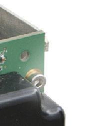
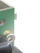
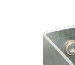
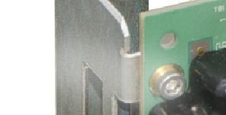
33 Flame Ionization Detector 4.2 Replacing the FID Mesh Filter Purge Coil and Filter Older analyzers had coils of stainless-steel tubing to provide an exhaust path for purged spaces. In newer analyzers this has been replaced by a metal filter or eliminated altogether. The two devices are shown in the photo below. Figure 4-1 Purge Coil compared with Metal Filter 4.2 Replacing the FID Mesh Filter This section describes the procedure to replace the mesh filter inside the FID in the Maxum II. The mesh filter is a small round filter located inside the combustion chamber of the FID. This filter is for the combustion air input. Because of the very small diameter of the air restrictor though which combustion air passes, it is unlikely that the filter will become clogged. Because it is difficult to remove this filter without damaging it, in the event that the filter does become clogged or it should become necessary to remove the filter for some reason, then it should be replaced and not reused. It will be necessary to power down the analyzer for this procedure. When performing this procedure, it should NOT be necessary to remove the FID from the Maxum II. The following figures are intended for use as a reference throughout the procedure. The numbers in the diagrams relating to individual components are referenced in parentheses in the procedure steps Detector Body (Bottom) 4. Filter 5. Retainer Clip - Small 6. Retainer Clip - Large 3 Figure 4-2 FID Mesh Filter and Retaining Clips Siemens Spares Service Manual, May 2018, A5E
34 Flame Ionization Detector 4.2 Replacing the FID Mesh Filter Quartz Jet Assembly Flame Arrestor Insert Assembly 12. Graphite Seal 2. Flat Washer 13. Hammer Drive Screws (for Label) 3. Detector Body (Bottom) 14. Label 4. Filter 15. Socket Heat Cap Screw 5. Retainer Clip - Small 16. Detector Body (Upper) 6. Retainer Clip - Large 17. Teflon Seal 7. Outer Ferrule 18. Collector 8. Graphite Ferrule 19. Socket Heat Cap Screw (M5 x 60) 9. Pressure Ferrule 20. Flame Arrestor Bushing 10. Burner Nut 21. Flat Washer 11. Quartz Jet (with flame tip nozzle) 22. Flame Arrestor Figure 4-3 FID Assembly 34 Service Manual, May 2018, A5E
35 Flame Ionization Detector 4.2 Replacing the FID Mesh Filter Procedure to Replace Mesh Filter 1. Shut off the detector Hydrogen and allow the detector to cool down. Carrier gas should remain on during cool down to prevent condensation. 2. Turn off all supply gasses. WARNING Possible ignition source. Failure to follow proper safety procedures may result in injury or death. If the analyzer is equipped with a purged methanator and explosive gasses are present, it is necessary to wait at least 8 minutes for the methanator to cool after powering down the analyzer before opening the analyzer door. 3. Power off the analyzer. 4. Remove Cap Screws (19) and detach Upper Detector Body (16) from Lower Detector Body (3). CAUTION Possible ignition source. Failure to follow proper safety procedures may result in injury or death. Do not open the FID with the flame burning or with the power on. 5. Unscrew Burner Nut (10) and remove the Quartz Jet and attached hardware (7, 8, 9, 10, and 11). Set these items aside on a clean, lint free cloth. 6. Using a small flat-head screwdriver or similar tool, remove the Small and Large Retainer Clips (5 and 6). 7. Turn on the air supply to the FID in order push the Mesh Filter (4) up so that it can be removed. If turning on the air supply does not dislodge the Mesh Filter (4), use a flat screwdriver to carefully pry up the Filter (be careful not to scratch the surface of the FID body. 8. Turn off the FID combustion air. 9. Discard the old Mesh Filter (4) and install a new one in the FID. 10.Re-install the Small and Large Retainer Clips (5 and 6) 11.Re-insert the Quartz Jet and attached hardware (7, 8, 9, 10, and 11) into the FID Bottom Body (3). Verify that the nozzle tip of the Quartz Jet (11) is still adjusted correctly (there should be 10.5 mm from the nozzle tip to the Lower Body (3). 12.Tighten the Burner Nut (10) with fingers. Then retighten one quarter to one half rotation using a wrench. The nozzle can break if it is tightened more. 13.Replace the graphite seal (12) before reassembling the FID body. 14.Reattach Upper Body (16) and Lower Body (3) and reinstall Cap Screws (19). Tighten Cap screws firmly but do not over tighten (about 1/2 turn past finger tight). 15.Power the analyzer back on. 16.After the oven and FID has had time to heat up, check the flows and light the flame. Siemens Spares Service Manual, May 2018, A5E
36 Flame Ionization Detector 4.3 Replacing the FID Quartz Jet 4.3 Replacing the FID Quartz Jet This section describes the procedure to replace the Quartz Jet inside the FID in the Maxum II. The Quartz Jet is a thin quartz tube that includes the burner nozzle tip for the FID flame. This item rarely needs replaced. It will be necessary to power down the analyzer for this procedure. When performing this procedure, it should NOT be necessary to remove the FID from the Maxum II Procedure to Replace Quartz Jet 1. Shut off the detector Hydrogen and allow the detector to cool down. Carrier gas should remain on during cool down to prevent condensation. 2. Turn off all supply gasses. WARNING Possible ignition source. Failure to follow proper safety procedures may result in injury or death. If the analyzer is equipped with a purged methanator and explosive gasses are present, it is necessary to wait at least 8 minutes for the methanator to cool after powering down the analyzer before opening the analyzer door. 3. Power off the analyzer. 4. Remove Cap Screws (19) and detach Upper Detector Body (16) from Lower Detector Body (3). 5. Unscrew the Burner Nut (10) and remove the Quartz Jet and attached hardware (7, 8, 9, 10, and 11). 6. Detach the Quartz Jet (11) from the Ferrules (7, 8, 9) and the Burner Nut (10). Make note of the way they are assembled. 7. If Quartz Jet (11) is dirty or clogged, it may be possible to clean it using solvent in an ultrasonic cleaner. However, replacement is recommended. If attempting to clean the quartz jet, allow any excess solvent to evaporate before reinstalling. 8. Assemble the replacement (or cleaned) Quartz Jet (11) and associated hardware (7, 8, 9, and 10). 9. Reinsert the Quartz Jet (and other hardware) into the Lower Detector Body (3). Before tightening the Burner Nut (10), adjust the nozzle (flame tip). The distance from nozzle tip to the Lower Body (3) should be 10.5 mm. Tighten the Burner Nut (10) with fingers. Then retighten one quarter to one half rotation using a wrench. The nozzle can break if it is tightened more. 10.Replace graphite seal (12) between the Upper Detector Body (16) and Lower Detector Body (3) before reassembling the FID body. 11.Reattach Upper Body (16) and Lower Body (3) and reinstall Cap Screws (19). Tighten Cap screws firmly but do not over tighten (about 1/2 turn past finger tight). 36 Service Manual, May 2018, A5E
37 Flame Ionization Detector 4.4 Replacing the FID Igniter 12.Power the analyzer back on. 13.After the oven and FID has had time to heat up, check the flows and light the flame. 4.4 Replacing the FID Igniter This section describes the procedure to retrofit the FID igniter in the Maxum II. This involves replacing the original FID igniter module with a new version FID igniter module. The procedure also involves replacing of some of the related hardware, such as the purge tube and heater assembly. It will be necessary to power down the analyzer for this procedure Procedure - Parts A parts kit (Siemens part number for 115V, for 230V) is required for this procedure. This kit contains the following items. Part Number Description Quantity A5E TUBE, FID PURGE 1 A5E GASKET, FID PROTECTIVE PIPE GROMMET, 1-1/32 ID, 1/16 GR, 1-3/4 OD 1 A5E BUSHING, FID PURGE TUBE SCREW, M3X 4, SOCKET HEAD CAP, SST WASHER, M3, HELICAL SPRING LOCK, SST 1 A6X O-RING, SIZE 020, X.O70, KALREZ IGNITER,FID ASSEMBLY, MAXUM II 1 A5E STRAP, GROUND, FID 1 A5E (115V) ASSEMBLY, HEATR, FID/FPD 1 A5E (230V) A5E COVER, DETECTOR, FID 1 A5E PURGE FILTER, 2.0 MICRON, THREAD 1 A5E WASHER,.375"X.190"X.031", 25% GF PTFE 1 The list above is provided for reference only. The official parts list for the kit is included with the kit when it is shipped. Also required is an appropriate tool kit. A lubricant such as Krytox 240 AC or equivalent will be needed in order to lubricate the new grommets. If the EC Cover Plate Gasket (Part Number ) is damaged, a replacement gasket will be required as well. Read this entire procedure before planning the work to make sure that necessary items are on hand. Siemens Spares Service Manual, May 2018, A5E
38 Flame Ionization Detector 4.4 Replacing the FID Igniter Procedure - Removing the Detector Note All figures are located at the end of this procedure. 1. From GCP, create a database backup of the Maxum analyzer that is to be modified (See the Gas Chromatograph Portal User Manual for instructions). 2. From GCP, verify operation of analyzer. Verify that there are no alarms or that all alarms are accounted for. (See the Gas Chromatograph Portal User Manual for instructions). 3. Verify that all parts of the new FID igniter kit are on site prior to starting. Contents of the kit are listed in the inventory list that is shipped with the kit. 4. Extinguish the flame to the FID either by shutting off the air supply to the detector (for hydrogen carrier) or shutting off the hydrogen to the detector (if not using hydrogen carrier). In order to prevent condensation in the detector, allow carrier to flow for several minutes after flame is extinguished. Use a mirror to check for condensation at the FID vent to verify the flame is not lit (no condensation means the flame is not lit). WARNING Possible ignition source. Failure to follow proper safety procedures may result in injury or death. If the analyzer is equipped with a purged methanator and explosive gasses are present, it is necessary to wait at least 8 minutes for the methanator to cool after powering down the analyzer before opening the analyzer door. 5. Power down the analyzer. 38 Service Manual, May 2018, A5E
39 Flame Ionization Detector 4.4 Replacing the FID Igniter 6. Open the electronics enclosure door, mezzanine door, and oven door. Use a 4mm Allen wrench if necessary and be careful not to place tension on the ribbon cable connecting to the Maintenance Panel. Heater Control from DPM Detector Personality Module (DPM) Flame Ionization Detector (FID) FID RTD Leads Igniter Signal FID Bias (300V) FID Output Signal Oven Heater Power from PECM FID Heater Power from PECM Filament Detector Figure 4-4 Typical FID Connections 7. Disconnect the FID heater power cable from the PECM. Note the connector location. 8. Disconnect the FID heater RTD cable from the DPM connector board. Note the connector location. Siemens Spares Service Manual, May 2018, A5E
40 Flame Ionization Detector 4.4 Replacing the FID Igniter 9. Disconnect the FID bias, igniter, and signal cables from the DPM making note of the connector locations. 10.Disconnect tubing from the FID flame arrestor insert tube in the oven. Old Igniter FID Bottom Body Figure 4-5 Flame Arrestor Insert FID Assy Bottom with Original Igniter Tubing Connection 11.Remove the flame arrestor insert from the FID bottom body using a 9/16" open-end wrench. Narrow End of FID Bottom Body Insert Washer FID Flame Arrestor Insert Figure 4-6 FID Flame Arrestor 40 Service Manual, May 2018, A5E
41 Flame Ionization Detector 4.4 Replacing the FID Igniter 12.Remove the ¼ " vent tube from the top of the FID block using a 9/16" open-ended wrench. Vent Tube Figure 4-7 FID Vent Tube Location on FID Assy 13.Using a 3.0mm Allen wrench, remove the FID cover set screw from the front of the FID Assembly. Cable tie (cut and discard) FID body Purge tube screws (4) (reuse) FID purge tube (discard) C Igniter assembly (discard) EC cover plate (discard) FID bottom body B Pipe gasket (discard) Thermal gasket (remains on FID) Setscrew for FID bottom body D Heater purge tube (discard) FID mounting plate Heater assembly (discard) A Cover setscrew Figure 4-8 FID FID Parts (with Old Igniter) Heater assembly screws (4) (reuse) 14.Remove the cover from the FID block by pulling up and out, and then remove the insulation from the FID block. Siemens Spares Service Manual, May 2018, A5E

42 Flame Ionization Detector 4.4 Replacing the FID Igniter 15.Disconnect utility gas lines from the FID at the connecting union using a 5/16" open-end wrench. Temporarily label the gas line leads to make sure they can be reconnected correctly. A Disconnect FID vent tube Disconnect C utility gas at unions on the ends of supply lines (up to 3) D EC cover plate nuts (4) B Cover setscrew hole E FID mounting plate screws (4) Figure 4-9 Removing the FID Assembly (Typical Installation) 16.Remove the four M4 nuts from the FID EC cover plate using a 7mm nut driver. 17.Using a 2.5mm Allen wrench, remove the four M4 screws that secure the FID mounting plate to the mezzanine. 18.Remove the FID assembly from the mezzanine by pulling up and then out when the FID bottom body clears the hole Procedure - Igniter Replacement Note A clean work surface should be used for disassembly of the old igniter and installation of the new igniter. This is to prevent contamination of the detector gas inputs and electrical contacts. 42 Service Manual, May 2018, A5E

 Detector bushing (A5E41666802001) and o-ring (A6X19905099) Utility gas lines (Do not disconnect here.")
43 Flame Ionization Detector 4.4 Replacing the FID Igniter Detector Bushing Ground strap set screw goes here FID cover ula Ins Hole for purge filter n tio Insulation Se Install signal cable so end is aligned with igniter cable ends d groun w for e r c s t strap Igniter rg Pu FID Insulation ub et e Mounting/ground strap FID purge tube grommet FID body EC cover plate (A5E ) Heater purge tube sealing grommet (Heyco) (A5E ) Detector bushing (A5E ) and o-ring (A6X ) Utility gas lines (Do not disconnect here. Disconnect at unions on the ends of supply lines ) Purge filter (A5E ) and washer (A5E ) Pipe gasket (A5E ) Heater purge tube Thermal gasket ( ) Heater assembly Setscrew for FID bottom body FID mounting plate Setscrew for FID cover Figure 4-10 Heater block mounting screws (4) FID Installation Exploded Diagram 1. Remove the four screws that secure the purge tube to the electrodes of the detector. 2. Pull the purge tube about 1 inch away from the detector assembly and carefully remove the wires from the electrodes. 3. The purge tube with its bushing and gasket, EC cover plate, and igniter assembly will not be reused. Set these items aside. However, the screws that were used to connect the tube to the detector will be reused. 4. Remove the setscrew for the FID bottom body to separate the detector heater and mounting plate. 5. Remove the old heater assembly. ( ) This will not be reused. Siemens Spares Service Manual, May 2018, A5E
 on the FID mounting plate using the 4 screws removed from the old heater assembly.")
44 Flame Ionization Detector 4.4 Replacing the FID Igniter 6. Install the new FID heater assembly (A5E for 115V, A5E for 230V) on the FID mounting plate using the 4 screws removed from the old heater assembly. Figure 4-11 Heater Assembly Note Do not disassemble the heater block assembly. Disassembling the heater block voids the hi-pot testing. 7. Install the Kalrez high-temperature O-ring (A6X ) into the groove on the new purge tube bushing. See New Bushing (with Tab for Connecting Strap). 8. Install the new purge tube bushing (A5E ) onto the FID using the 4 screws removed from the purge tube earlier in this procedure. The new pipe gasket (A5E ) should be positioned between the bushing and the FID body. Install the bushing such that the tab (used to attach the igniter fastening strap) is on the bottom. 9. Using a 2.5mm hex wrench, attach the mounting strap to the new igniter board. Use an M3 x 4 socket head cap screw ( ) from the kit for this connection. See New Igniter Attachment to Detector. Note Because the wires from the igniter to the electrodes are stiff, it is best to plug the wires in before attaching the strap to the bushing. 10.Plug both igniter wires into the appropriate detector electrode positions. The wires from the igniter board to the DPM should not be connected yet. 11.Using a 2.5mm Allen wrench, attach the new igniter board to the bushing on the detector assembly using the fastening strap. Use a socket head cap screw (item 6) and lock washer (item 7) from the kit for this connection. Note that the igniter board is installed with the flat side up and the round transformer down. See New Igniter Attachmnment to Detector. 44 Service Manual, May 2018, A5E

 13.")


45 Flame Ionization Detector 4.4 Replacing the FID Igniter 12.Plug the white signal wire (from the DPM) into the appropriate detector electrode position. See Electrode Connections for New Igniter. The wire should not be connected at the DPM end yet. White Signal Wire (from DPM) Figure 4-12 Red Wire (from igniter) FID New Igniter Electrode Connections Note: The black wire appears blue due to a Teflon coating over the wire. Black Wire (from igniter) 13.Place the white signal wire (from the DPM, often covered by black heat-shrinkable tubing) across the top of the new igniter board. Figure 4-13 FID Wiring 14.Insert the unplugged ends of the wires into the new FID purge tube and slide the purge tube over the igniter board and wiring. Make sure that the white signal wire remains positioned against the flat top side of the igniter board. Place the end of the purge tube with the flat area around the hole towards the detector. Detector Bushing Figure 4-14 FID Purge Tube and Bushing Orientation 15.Line up the hole on the new purge tube with the hole on the bushing. The holes will be on the bottom of the purge tube when the assembly is in the upright, operating position. Siemens Spares Service Manual, May 2018, A5E


46 Flame Ionization Detector 4.4 Replacing the FID Igniter 16.Insert the purge filter (A5E ) through the washer (A5E ), and screw into the bushing to secure the purge tube. 17.If the new grommets are not installed in the holes on the new EC cover plate or on the purge tubes, then install them now. 18.Apply a coating of Krytox 240 AC or similar lubricant around the inside diameter of the grommets to allow for easy sliding of the new purge tube. 19.Feed the detector wiring through the appropriate holes on the new EC cover plate and install the cover plate onto the detector assembly Procedure - Reinstalling the Detector 1. Inspect the FID EC cover plate gasket ( ) and replace if worn or damaged. 2. Inspect the FID thermal gasket ( ) and replace if damaged. Retrieve any gasket fragments that may have remained in or on top of the oven. If replacing the gasket, clean the mating surface on the FID, and remove the paper backing to expose the adhesive. Gasket installed on FID lower body Adhesive Figure 4-15 FID Thermal Gasket To oven fitting 3. Route the FID Module Assembly wiring into the EC and install the module into the analyzer. Make sure that the FID bottom body fits into the hole at the bottom of the mezzanine section. 4. Install the 4 M4 screws into the FID mounting plate and tighten using a 2.5mm Allen wrench. 5. Make sure that the EC cover plate gasket is in the correct position and install the 4 M4 nuts. Tighten the nuts using a 7mm nut driver. Verify that the nuts are not over-tightened by making sure that the gasket is not pushed out more than about 1/16" along the edges of the EC cover plate. 6. Connect the utility gas lines to the correct connecting unions and tighten using a 5/16" openend wrench. Remove the temporary labeling that was added earlier in this procedure. 7. Place the insulation and then the FID cover onto the FID block. 46 Service Manual, May 2018, A5E
47 Flame Ionization Detector 4.5 FID Specifications 8. Install the FID cover set screw and tighten using a 3mm Allen wrench. Note The next step is important in order to maintain the explosion proof protection of the FID. The threads of the FID flame arrestor must be clean and lubricant or other substances must NOT be applied to the threads. 9. Place the FID flame arrestor insert and washer into the FID bottom body and tighten using a 9/16" open-end wrench. Make sure the flat washer fits into the recessed cavity at the lower end of the FID bottom body to prevent leaks. See Figures 3-4 and Connect the FID flame arrestor insert tubing to the correct connection union in the oven using either a 1/4" or 5/16" open-end wrench depending on the fitting size. 11.Route the bias cable, the igniter cable, and the signal cable through the EC and connect them to the FID DPM board locations from which they were unplugged earlier in this procedure. 12.Route the FID heater RTD cable through the EC and plug it into the DPM location from which it was unplugged earlier in this procedure. 13.Route the FID heater power cable through the EC and plug it into the PECM location from which it was unplugged earlier in this procedure. 14.Route the FID heater ground braid through the EC and connect to the appropriate ground lug from which the old one was disconnected. 15.Turn on utility gases and check for leaks. 16.Turn on power to the analyzer and switch the valves checking all possible flow paths for leaks. Refer to plumbing diagram provided in the custom documentation package for flow paths. 17.Turn up oven air to the normal setting and allow the oven to come to temperature and stabilize. 18.Set all gas flows after the detector is up to its temperature set point. 19.With the new igniter, it will be necessary to start Real Time Chromatograms on the HMI in order to light the FID flame. On the HMI, choose the Maintenance Menu, and then select option 5 (Detectors & Real Time Chroms). Then highlight the appropriate FID and then press "View Chrom". 20.At this time you can ignite the FID using the HMI. 21.After 15 to 30 minutes the analyzer will be ready for operation. Verify that the FID operates correctly and put analyzer back on line. 4.5 FID Specifications Table 4-1 Flame Ionization Detector (FID) Parameter Target Components Value Carbon Measurement Type Mass Siemens Spares Service Manual, May 2018, A5E

 Dynamic Range 10 7 Linear Range 10 6 Selectivity 0 to 100 ppm")


48 Flame Ionization Detector 4.6 Filament Detector Parameter Value Smallest Measuring Range (at 60 C oven temperature) 0 to 1 ppm ±3% Typical Measuring Range (at 60 C oven temperature) Dynamic Range 10 7 Linear Range 10 6 Selectivity 0 to 100 ppm ±1% FS up to 0 to 100% ±0.5% FS Combustible Components Temperature Range 105 to 260 C 4.6 Filament Detector The Filament Detector is a two-cell device that provides a reference and a sample sense signal, typically used in applications along with the FID. Component Locations Figure 4-16 FID and Filament Detector in Typical Analyzer 48 Service Manual, May 2018, A5E
49 Flame Ionization Detector 4.6 Filament Detector 3(&0 %DVH '30 ),' +HDWHU &RQWURO,Q IURP '30 ),' +HDWHU &RQWURO 57' 6HQVH ),' )LODPHQW 'HWHFWRU,Q ),' +HDWHU &RQWURO 2XW )LODPHQW 'HWHFWRU Figure 4-17 FID with Filament Detector, Typical Application Filament Detector Assembly Details *DV 7XELQJ *DV 7XELQJ 0 +DUGZDUH )LODPHQW 'HWHFWRU %ORFN )ORZ 'LYHUWHU,QVHUWV 2 5LQJV 0 +DUGZDUH )LODPHQW %RDUG 5HIHUHQFH 5HG %ODFN :LUH 3DLU 6HQVH :KLWH %OXH :LUH 3DLU Figure 4-18 : LU H H 6 DOH G ) QJ LW WL & DE V $V O H HP &HOO )LODPHQW &RYHU EO\ 3URSHU RULHQWDWLRQ RI )ORZ 'LYHUWHU,QVHUWV Filament Detector Exploded View Siemens Spares Service Manual, May 2018, A5E
50 Flame Ionization Detector 4.6 Filament Detector Replacing the Filaments 1. Remove the two bolts in the bottom of the detector block. 2. Separate the detector body (bottom) and detector cap (top) to allow access to the filament board. 3. Note location of each wire and disconnect from board. Wires are paired; Sense is White and Blue, and Reference is Red and Black. 4. Remove the screw and both washers holding the board in place. 5. Carefully lift board out of Detector block. 6. Discard the board and O-rings. Do not attempt to reuse old O-rings. 7. Remove the two metal inserts. These CAN be reused. 8. Inspect the metal flow diverter inserts for damage. 9. Before installing new board, examine the mounting surface and the holes for the filaments to verify there is no contamination or scratches on the machined surface. If there is contamination on the surface, clean it using a lint free cloth and a cleaning solvent such as acetone or hexane. If the surface is scratched it may be necessary to replace the complete assembly. Note The elements on the board are exposed and are very delicate. Handle the board only by its edges. Hands and tools must be clean. 10.Install the metal inserts in the detector block. These inserts should be installed with the groove perpendicular to the tube holes in the block (so that air cannot flow in a straight path between the holes). 11.Install the new O-rings in hole in the Detector Block. It is also possible to install the O-rings on the filament board instead of in the hole. If installing the O-rings on the board, be careful not to damage the element. 12.Install the Board into the Detector Block. When installing the board, exercise caution not to damage the exposed elements. 13.Reinstall the Flat Washer, Lock Washer, and Button Head Hex Screw. Do not over tighten the screw as this can damage the Board 14.Reconnect wiring to the board. Wiring MUST be connected to the same cells as before. Verify all termination points. Note The color coding information for the wiring should be on the Detector Certification Label. Also note that there are two wires of each color. For a specific cell it does not matter which wire is connected to which lead as long as the color is correct. 15.Before installing cover back on the Detector Block, turn on carrier air to verify there are no leaks between the Board and the Block. Turn off carrier after this check is complete. 16.Set the cover in place and reinstall the 4 screws and lockwashers that secure the cover to the detector block. 50 Service Manual, May 2018, A5E
51 Flame Ionization Detector 4.7 Methanator 4.7 Methanator Methanator Function The methanator is used with a Flame Ionization Detector (FID) when it is necessary to detect carbon dioxide (CO 2 ) or carbon monoxide (CO). In the methanator CO 2 and CO are chemically changed to methane using excess hydrogen and a catalytic reaction. The concentration of methane, which can be detected using an FID, is proportional to the concentration of CO 2 and CO. In this manner, it is possible to detect CO 2, CO and other types of gases using an FID. The methanator design consists of a stainless steel tube that is filled with a catalyst. The tube is heated using a heater cartridge, and an RTD temperature sensor and control circuit regulates the temperature. The tube is heated to approximately 400 C and the sample with hydrogen carrier is passed through the tube. The CO 2 and/or CO (depending on the exact temperature) are converted into methane for detection by the FID. Two versions of the methanator exist for use in the Maxum edition II. The original is protected by purging/pressurization. The more recent version is protected in an explosion proof enclosure. Both versions are installed in the detector compartment of the Maxum II Airbath/ Airless Oven configuration. Features of Both Methanator Models As protection measure, the gas inlets and outlets that enter and leave the methanator are configured as flame arrestors. In addition, both versions of the methanator assembly are insulated to prevent the surface temperature of the methanator from exceeding 180 C. Surface temperatures for the explosion proof/flameproof methanator are significantly lower than 180 C. NOTICE Installation of a Methanator restricts the temperature range of the analyzer The ambient temperature operating range of a methanator-equipped analyzer is 0 C T a +50 C. Siemens Spares Service Manual, May 2018, A5E

52 Flame Ionization Detector 4.7 Methanator Purged Methanator Although the purged/pressurized methanator assembly is installed in the detector compartment, it is installed inside a protective cover that limits air passage. The interior of the assembly is connected to the EC using a pipe which contains the electrical wiring for the methanator. This pipe and the protective cover over the assembly effectively make the interior assembly part of the pressurized EC. As described in AUTOHOTSPOT of this manual, this higher pressure area prevents flammable vapors and gases from entering the methanator. Figure 4-19 Purged Methanator The purged methanator was replaced by the explosion-proof methanator described in the following section. 52 Service Manual, May 2018, A5E

53 Flame Ionization Detector 4.7 Methanator Explosion-Proof Methanator The more recent version of the methanator is designed with an explosion proof/flameproof enclosure as described in the Safety Protection Principles section of this manual. This design eliminates the need to maintain a pressurized methanator enclosure as well as reducing some of the necessary safety measures required for maintenance of the Maxum II when a methanator is installed. Figure 4-20 Explosion-proof Methanator For more information see the Maxum II Explosion Protection Safety Standards Manual (A5E ) ( Methanator Specifications Table 4-2 Methanator Parameter Value Non-Ex Methanator Ex Methanator Classification n/a Ex d IIB+H2 Maximum Operation Temperature 400 C 400 C Heater 115 or 230 VAC 115 or 230 VAC Gas Supply H 2, ml/minute H 2, ml/minute Ambient operating temperature for Methanator-equipped Maxum II 0-50 C Siemens Spares Service Manual, May 2018, A5E
54 Flame Ionization Detector 4.7 Methanator Methanator Maintenance Considerations Purged Methanator The methanator should be inspected regularly to ensure there is no physical damage affecting the integrity of the protective cover and to verify that the protective cover is fastened securely in place. The conduit pipe should be attached snugly in accordance with local safety practices. Seals for pipe and cover should fit securely to prevent excessive escape of purge air from around the device. All gas connections must be made through the tubing that is supplied from the factory and is part of the methanator assembly. This tubing should never be cut or shortened. If there is any physical damage, remove power from the device and replace it. WARNING Risk of ignition and explosion The purged/pressurized methanator must not be operated without purge/pressurization unless it has been verified that the area is free of explosive gases and vapors. This includes opening the door to the EC for routine maintenance. If the purge air supply of the Maxum II is interrupted during operation, it is imperative that the analyzer be powered down. Once powered down, the electronics-cabinet door must be kept closed for at least 30 minutes. A 30-minute delay is necessary to give the methanator time to cool down sufficiently. If the door to the electronics cabinet is opened prematurely, explosive gas or vapor can ignite by entering the electronics cabinet and then entering the methanator through the conduit tube. Failure to follow proper safety procedures may result in equipment damage, severe injury, or death. Explosion Proof Methanator The methanator should be inspected regularly to ensure there is no physical damage to the enclosure and to verify the screw-on cap is fully tightened. Secure the setscrew sufficiently to require a tool to open the device. The conduit pipe screws into a seal at the methanator housing. Up to that point, it is part of the purged space of the EC. The pipe should be attached securely in accordance with local safety practices. The seals for the pipe entry into the EC should fit securely to prevent excessive escape of purge air. WARNING Risk of ignition and explosion The screw-on cap of the explosion proof/flameproof methanator must not be removed unless it has been verified that the area is free of explosive gases and vapors or unless the methanator has been given sufficient time to cool down (at least 30 minutes without power). Failure to follow proper safety procedures may result in equipment damage, severe injury, or death. 54 Service Manual, May 2018, A5E

55 Flame Ionization Detector 4.8 Air Treater 4.8 Air Treater The FID is an extremely sensitive sensor of hydrocarbons. As part of the sensing system, the FID uses a flame that burns hydrogen fuel mixed with air. Because the FID is so sensitive, the air used in the combustion process must be completely free of hydrocarbons. Otherwise noise appears on the detector signal. To provide clean air for the Flame Ionization Detector (FID), the Maxum II uses a catalytic device known as an Air Treater to remove hy drocarbons from ordinary plant instrument air. The Air Treater is an independent unit moun ted near the Maxum II. It consists of an ex tremely hot combustion chamber and a cata lyst. Instrument air flows through the combus tion chamber and interacts with the catalyst to convert any trace hydrocarbons into CO2 and water. The resulting clean air and any formed water vapor are then delivered to the analyzer detector system. The combustion chamber of the Air Treater is housed in an insulated explosion proof enclo sure. This enclosure prevents hot surfaces from contacting the atmosphere in the area of analyzer installation, and will contain an ex plosion if combustible gases get inside the air treater. The Air Treater is connected to electrical pow er by means of wiring installed in approved conduit. Wiring connections are not supplied by the factory and must be made in the field. Air Treater The instrument air flows into and out of the explosion proof enclosure through specified flame arrestors. These flame arrestors are supplied by the factory and are firmly attached to the Air Treater assembly Air Treater Maintenance Considerations The Air Treater must be inspected regularly for any physical damage. It must be handled carefully and not dropped or damaged in any other way. If it is damaged, remove power and replace the unit. The electrical power connections to the Air Treater must be made with wires installed in conduit or connected through cable glands using practices that conform to local safety requirements. All conduit and wiring connections must be tightened and made according to local practice. The completed installation must be inspected by personnel trained in safety practices. Siemens Spares Service Manual, May 2018, A5E
Installing the assembly SIMATIC. Installing the assembly. Overview 1. Installing the assembly. Getting Started A5E
 Overview 1 2 SIMATIC Getting Started 03/2013 A5E03973659-01 Legal information Warning notice system This manual contains notices you have to observe in order to ensure your personal safety, as well as
FPD - Flame Photometric Detector
 FPD - Flame Photometric Detector FPD Overview - The FPD detector is can be configured for 2 modes of operation, one is highly selective for Sulfur compounds and the other mode highly selective for Phosphorus
Maxum II. PD PA AP Explosion Protection Safety Standards. General Information for the User 1. Safety Systems - Purging 2. Safety Systems - Oven 3
 General Information for the User 1 Safety Systems - Purging 2 Maxum II PD PA AP Explosion Protection Safety Standards Safety Systems - Oven 3 Valves, Detectors, and External Systems 4 Safe Operation 5
Operating Instructions Edition 11/2005. Process monitoring Ex-barrier for Diagnostics Unit SITRANS DA400 7MJ2010-1AA. sitrans
 Operating Instructions Edition 11/2005 Process monitoring Ex-barrier for Diagnostics Unit SITRANS DA400 7MJ2010-1AA sitrans Introduction 1 General safety instructions 2 SITRANS Process monitoring Ex-barrier
Installing a Fast Oven Upgrade Kit
 Agilent 6850 Series II Network GC System Accessory G3350B There are three Fast Oven upgrade kits: 120 V, 200 V, and 230 V. The following table indicates what each kit contains: Description Quantity 120
1320 Detectors. 1 of 30. Jun Illustrated Parts Breakdown Agilent 6890 Gas Chromatograph Service Manual
 20 Detectors This section contains an illustrated parts breakdown for each of the following 6890 GC detectors and related components. Electron Capture Detector (ECD) Flame Ionization Detector (FID) Nitrogen
Safe Operation Manual. Honeywell IQ Force Gas Detector
 Safe Operation Manual Honeywell IQ Force Gas Detector Honeywell Analytics 800-663-4164 403-248-9226 Fax 403-575-3708 03JUN2012 P/N 50105843-047 Version 01 http://www.honeywell.com HONEYWELL IQ Force PERSONAL
TCD-to-FID Series Connection on a 6820 GC, Accessory G4319A
 TCD-to-FID Series Connection on a 6820 GC, Accessory G4319A Installation Guide The TCD-to-FID Series Connector connects output flow from a Thermal Conductivity Detector (TCD) to the column inlet of a Flame
HFID Heated Total Hydrocarbon Analyzer Module
 Product Data Sheet PDS 103-685.A01 October, 2003 NGA 2000 HFID Heated Total Hydrocarbon Analyzer Module Heated analyzer designed to operate from 200 F to 400 F Eliminates loss of hydrocarbons due to condensation
Chemistry Instrumental Analysis Lecture 29. Chem 4631
 Chemistry 4631 Instrumental Analysis Lecture 29 Gas Chromatography Detectors Gas Chromatography Monitors the column effluent and produces an electrical signal that is proportional to the amount of analyte
Multi-Function Cooktop
 INSTALLATION GUIDE Multi-Function Cooktop Contents Wolf Multi-Function Cooktop.................... 3 Multi-Function Cooktop Specifications............ 4 Multi-Function Cooktop Installation...............
SITRANS. Temperature transmitter Functional safety for SITRANS TW. Introduction. General safety instructions 2. Device-specific safety instructions
 Introduction 1 General safety instructions 2 SITRANS Temperature transmitter Device-specific safety instructions 3 Appendix List of Abbreviations/Acronyms A B Product Information Supplement to Operating
RK-05 Combustible Gas Transmitter Operator s Manual
 65-2405RK-05 Combustible Gas Transmitter Operator s Manual Part Number: 71-0180RK Revision: 0 Released: 2/16/11 RKI Instruments, Inc. www.rkiinstruments.com WARNING Read and understand this instruction
RK Multi Point Detector Operator s Manual
 65-2480RK Multi Point Detector Operator s Manual Part Number: 71-0198RK Revision: C Released: 11/26/14 RKI Instruments, Inc. www.rkiinstruments.com WARNING Read and understand this instruction manual before
TECHNICAL INSTRUCTIONS
 TECHNICAL INSTRUCTIONS 24-Month Maintenance Kit P/N 58015-02 For BMK2.0 (Nozzle Mix) Description of Document: This TID provides the procedures to perform recommended 24-Month maintenance on the following
INSTALLATION GUIDE Dual Fuel Ranges
 INSTALLATION GUIDE Dual Fuel Ranges Contents Wolf Dual Fuel Ranges......................... 3 Safety Instructions............................ 4 Dual Fuel Range Specifications.................. 5 Dual Fuel
22 The Flame Ionization Detector
 22 General Information FID pneumatics Special considerations Conditions that prevent the detector from operating Detector shutdown Jets Automatic reignition Lit offset Procedure: Changing the auto-reignite
Process Gas Chromatograph
 A I T Applied Instrument Technologies FXi Series5 PRODUCT SPECIFICATIONS Process Gas Chromatograph PSS FXI-S5 The FXi Series5 Process Gas Chromatograph (PGC) continuously analyzes, measures, and reports
Installation Instructions Part No
 Heat Exchanger Cell Kit Cancels: New Installation Instructions Part No. 326600-751 IIK-310A-45-6 6-02 NOTE: Read the entire instruction manual before starting the installation. SAFETY CONSIDERATIONS Installing
Monitoring Flammable Vapors and Gases in Industrial Processes
 Monitoring Flammable Vapors and Gases in Industrial Processes Flammability Hazards Industrial fires and explosions happen more frequently than most people think. They cause downtime, property damage, injury
Process gas chromatography
 Siemens AG 2018 /2 Introduction / Introduction Overview is one of the most powerful measuring and analysis methods for process engineering. It is a procedure which is both discrete and extractive. This
Title: Standard Operating Procedure for Measurement of Total Hydrocarbon Using a Flame Ionization Detection
 Procedure No: SOP-020 Revision No: 1.0 (January 21, 2011) Page No.: 1 of 7 1. INTRODUCTION AND SCOPE To obtain timely data for the purpose of air quality assessment, air quality trend reporting, and to
Carbon Rack Enclosure
 USER S MANUAL Carbon Rack Enclosure CRxU Series SAVE THESE INSTRUCTIONS Please read this manual and follow the instructions for installation and use. Copyright 07 Cyber Power Systems, Inc. All rights reserved.
INSTALLATION, OPERATING & MAINTENANCE INSTRUCTIONS FOR 350 SERIES CIRCULATION HEATERS
 INDEECO Circulation Heaters are designed to provide years of trouble free operation if properly installed and maintained. Please read and follow these instructions for installing and maintaining the heater.
ACQUITY UPLC HT Column Heater Instructions
 ACQUITY UPLC HT Column Heater Instructions Note: This document is an addendum to Revision C of the ACQUITY UPLC System Operator s Guide. Contents: Topic Page Overview 1 Connecting the cable 4 Installing
Thermo Scientific. TRACE GC Ultra. Gas Chromatograph Maintenance and Troubleshooting Manual. PN , Revision March 2011
 Thermo Scientific TRACE GC Ultra Gas Chromatograph Maintenance and Troubleshooting Manual PN 31709180, Revision March 2011 TRACE GC Ultra Maintenance and Troubleshooting Manual March 2011 Edition Original
Operation and Maintenance Manual
 Operation and Maintenance Manual GDS-48 Remote Bridge Sensor for Combustible Gases AUTHORIZED DISTRIBUTOR: GasDetectorsUSA.com - Houston, Texas USA sales@gasdetectorsusa.com - 832-615-3588 CAUTION: FOR
Thermal Conductivity Detector on a 6820 GC, Accessory G4313A
 Thermal Conductivity Detector on a 6820 GC, Accessory G4313A Installation Guide This installation guide provides procedures for installing a Thermal Conductivity Detector (TCD) on an Agilent 6820 Gas Chromatograph
Model gffoz Process Ozone Sensor (In-Line)
") Date ECO# Rev Description Originator 9/15/97 1.0 First Publication DB 10/8/97 2.0 Miscelaneous corrections DB 10/28/97 3.0 Minor changes BM 5/1/98 3.1 Added CE compliance BM TM IN USA, INCORPORATED 87
Date ECO# Rev Description Originator 9/15/97 1.0 First Publication DB 10/8/97 2.0 Miscelaneous corrections DB 10/28/97 3.0 Minor changes BM 5/1/98 3.1 Added CE compliance BM TM IN USA, INCORPORATED 87
Installation Instructions Part No , Part No Part No
 Torsion-Flex Motor mount for PSC motors and Rigid-Mount for ECM motors Replacement Kit Cancels: New Installation Instructions Part No. 327752-401, Part No. 327753-401 Part No. 327754-401 IIK-310A-45-11
Process Gas Chromatographs MAXUM edition II
 Overview The is a universal process gas chromatograph for flexible process applications with a wide variety of analytical possibilities. The combines various functional modules with a flexible oven concept
RK-02 Multi Point Detector Operator s Manual
 65-2485RK-02 Multi Point Detector Operator s Manual Part Number: 71-0237RK Revision: A Released: 11/26/14 RKI Instruments, Inc. www.rkiinstruments.com WARNING Read and understand this instruction manual
SINAMICS G130. Cabinet design and EMC. Operating Instructions 05/2010 SINAMICS
 SINAMICS G130 Operating Instructions 05/2010 SINAMICS s Safety information 1 General 2 SINAMICS SINAMICS G130 Basic information about EMC 3 EMC-compliant design and control cabinet configuration 4 Cabinet
FIXED GAS ANALYZER (FGA)
") Gas Chromatography FIXED GAS ANALYZER (FGA) Productivity remains the primary goal of most work environments. Utilizing a gas chromatographic system capable of performing multiple analyses on a series of
Gas Chromatography FIXED GAS ANALYZER (FGA) Productivity remains the primary goal of most work environments. Utilizing a gas chromatographic system capable of performing multiple analyses on a series of
GASS Module. User Manual. Gas Analysis Sampling System PERMA PURE
 GASS Module Gas Analysis Sampling System User Manual PERMA PURE 8 Executive Drive Toms River, N.J. 08755 Phone: 800-337-3762 732-244-0010 Fax: 732-244-8140 e-mail: info@permapure.com Web Site: www.permapure.com
TECHNICAL INSTRUCTIONS
 TECHNICAL INSTRUCTIONS 24-Month Maintenance Kit P/N 58025-06 For BMK2.0LN Boilers Description of Document: This TID provides the procedures to perform recommended 24-Month maintenance on the following
SINAMICS G130. Cabinet design and EMC. Operating instructions 03/2011 SINAMICS
 SINAMICS G130 Operating instructions 03/2011 SINAMICS s Safety information 1 General 2 SINAMICS SINAMICS G130 Basic information about EMC 3 EMC-compliant design and control cabinet configuration 4 Cabinet
OPTION CA1, CA2, AND CA3 POWER VENTERS
 R HAZARD INTENSITY LEVELS 1. DANGER: Failure to comply will result in severe personal injury or death and/or property damage. 2. WARNING: Failure to comply could result in severe personal injury or death
Installation Instructions Dual Fuel Ranges
 Installation Instructions Dual Fuel Ranges E30DF74EPS E36DF76EPS E48DF76EPS 5995447082 2 Safety IMPORTANT SAFETY INSTRUCTIONS Safety Precautions Do not attempt to install or operate your unit until you
SITRANS T. SITRANS T Explosion protected temperature sensor. General information. Marking of the degree of protection. Range of uses.
 General information 1 Marking of the degree of protection 2 SITRANS T SITRANS T Explosion protected temperature sensor Operating Instructions Range of uses 3 Installation 4 Assembly and disassembly 5 Commissioning
OPERATORS MANUAL FOR Mi-T-M CORONA DISCHARGE OZONE GENERATORS
 OPERATORS MANUAL FOR Mi-T-M CORONA DISCHARGE OZONE GENERATORS CAUTION RISK OF INJURY! READ MANUAL BEFORE OPERATING! This manual is an important part of the Corona Discharge Ozone Generator and must remain
OPERATING AND MAINTENANCE MANUAL
 OPERATING AND MAINTENANCE MANUAL NVPOM-0104 TABLE OF CONTENTS Section Page 1 SPECIFICATIONS...1 1.1 Nova Plus Specifications...1-1 1.2 Warranty...1-2 2 GENERAL BURNER DESCRIPTION...2 2.1 Burner...2-1 2.2
DESIGN MANUAL MODEL GIR900 INFRARED COMBUSTIBLE GAS SENSOR
 DESIGN MANUAL MODEL GIR900 INFRARED COMBUSTIBLE GAS SENSOR 70086 The information in this doucment is applicable to sensors built in September, 2008 or later (Firmware 3.0) The information and technical
ClearFire. Startup Guide. Model CFH. Horizontal Steam Boiler
 ClearFire Model CFH Horizontal Steam Boiler Startup Guide 750-293 www.cleaverbrooks.com Improper installation, adjustment, service, or maintenance can cause equipment damage, personal injury, or death.
ATM Lighting sp. z o.o
 INSTALLATION AND MAINTENANCE MANUAL FOR EXPLOSIONPROOF LIGHT FITTING EXL390LED Carefully read the instructions before mounting the light fitting. ATM Lighting sp. z o.o., ul. Budowlanych 31, 80-298 Gdańsk,
Combustible Gas Sample-Draw Detector Operator s Manual
 35-3001-01 Combustible Gas Sample-Draw Detector Operator s Manual Part Number: 71-0282RK Revision: A Released: 8/3/17 www.rkiinstruments.com WARNING Read and understand this instruction manual before operating
RK Hydrogen Sulfide Transmitter Operator s Manual
 65-2331RK Hydrogen Sulfide Transmitter Operator s Manual Part Number: 71-0176RK Revision: B Released: 11/26/14 RKI Instruments, Inc. www.rkiinstruments.com WARNING Read and understand this instruction
ATM Lighting sp. z o.o
 INSTALLATION AND MAINTENANCE MANUAL FOR EXPLOSIONPROOF LIGHT FITTING EXL210LED Carefully read the instructions before mounting the light fitting. ATM Lighting sp. z o.o., ul. Budowlanych 31, 80-298 Gdańsk,
LABORATORY ULTRA ZERO AIR GENERATOR. ZAC-ULT Series USER MANUAL
 LABORATORY ULTRA ZERO AIR GENERATOR ZAC-ULT Series USER MANUAL 166 Keystone Drive Montgomeryville, PA 18936 Telephone: 215-641-2700 Fax: 215-641-2714 Email: mtgmmville@matheson-trigas.com INT-0261-XX rev
RK Carbon Monoxide Transmitter Operator s Manual
 65-2335RK Carbon Monoxide Transmitter Operator s Manual Part Number: 71-0177RK Revision: 0 Released: 4/12/11 RKI Instruments, Inc. www.rkiinstruments.com WARNING Read and understand this instruction manual
Installation Instructions
 Coupling Box Kit Cancels: IIK 340M-40-79 IIK 340M-40-88 9-05 Installation Instructions Part No. 320721-765, 330539-751, -752, -753, -754, -755, -756, and -757 NOTE: Read the entire instruction manual before
Advance Optima Continuous Gas Analyzers AO2060-Caldos15, -Caldos17, -Magnos106, -Uras14 Category 2G Analyzer Modules
 Advance Optima Continuous Gas Analyzers AO2060-Caldos15, -Caldos17, -Magnos106, -Uras14 Category 2G Analyzer Modules Operator s Manual 42/24-12 EN Rev. 4 Contents Page Preface 4 Safety Information General
Wide-Bore Heat Exchanger Installation Kit ( )
") 1090 High Performance Liquid Chromatograph Technical Note Wide-Bore Heat Exchanger Installation Kit (01090-68707) General Information 2 What You Will Need 3 4 Preparing the FPD Flow Cell 5 Preparing the
1090 High Performance Liquid Chromatograph Technical Note Wide-Bore Heat Exchanger Installation Kit (01090-68707) General Information 2 What You Will Need 3 4 Preparing the FPD Flow Cell 5 Preparing the
PME. Series Enclosures. Battery Enclosure (BE) Field Upgrade Installation Instructions. Effective: January, Alpha Technologies
 Field Upgrade Installation Instructions. Effective: January, Alpha Technologies") PME Series Enclosures Battery Enclosure (BE) Field Upgrade Installation Instructions Effective: January, 2004 Alpha Technologies Power Alpha Technologies. Protecting The Power in Communications. Preface
PME Series Enclosures Battery Enclosure (BE) Field Upgrade Installation Instructions Effective: January, 2004 Alpha Technologies Power Alpha Technologies. Protecting The Power in Communications. Preface
Outdoor kit. Models: RTG 199HE / RTG 199ME. Installation Instructions
 Installation Instructions Models: RTG 199HE / RTG 199ME Outdoor kit Warning: This kit must be installed by a qualified installer in accordance with these instructions and all applicable codes and requirements
POPULAR CONFIGURATION GCs Cryosulfur GC. System Overview
 System Overview The SRI CryoSulfur GC comes with everything you need to detect low-level sulfur compounds in gas samples. Since some sulfur compounds do not trap well, the CryoSulfur GC uses the CryoCooler
TECHNICAL INSTRUCTIONS
 TECHNICAL INSTRUCTIONS 24-Month Maintenance Kit P/N 58025-04 For BMK3.0LN Boilers Description of Document: This TID provides the procedures to perform recommended 24-Month maintenance on the following
White paper on the Dielectric Barrier Discharge Detectors. Introduction:
 White paper on the Dielectric Barrier Discharge Detectors. Introduction: This paper is a discussion of the dielectric barrier discharge detector. As such, it is intended to provide insight into the operating
TECHNICAL INSTRUCTIONS
 TECHNICAL INSTRUCTIONS Benchmark 3.0LN 24-Month Maintenance Kit# 58015-04 This kit applies to units with an Ignitor and a separate gas injector. For units with an Ignitor-Injector (P/N 58023), see Kit
ACQUITY UPLC H-Class Column Compartments Operator s Overview and Maintenance Information
 ACQUITY UPLC H-Class Column Compartments Operator s Overview and Maintenance Information Revision B Copyright Waters Corporation 2010 All rights reserved Copyright notice 2010 WATERS CORPORATION. PRINTED
Operator s Manual. Wet/Dry Vacuum with Detachable Blower 12 Gallon Model No. VBV1210 FOR YOUR SAFETY
 Wet/Dry Vacuums Operator s Manual Wet/Dry Vacuum with Detachable Blower 12 Gallon Model No. VBV1210 FOR YOUR SAFETY Read and understand this manual before use Keep this manual for future reference www.vacmaster.com
Owner s Information Manual
 48ES---A and 48VL---A Comfort and Performance 13 and 14 SEER Single Packaged Air Conditioner and Gas Furnace System With Puron (R---410A) Refrigerant Single and Three Phase 2---5 Nominal Tons (Sizes 24---60)
RK-05 Carbon Monoxide Detector Operator s Manual
 65-2433RK-05 Carbon Monoxide Detector Operator s Manual Part Number: 71-0189RK Revision: 0 Released: 5/17/11 RKI Instruments, Inc. www.rkiinstruments.com WARNING Read and understand this instruction manual
Safety. Operating instructions Ionization pilot burners ZAI, ZMI, ZKIH DANGER. Contents WARNING CAUTION Edition 12.11
 050560 Edition. D F NL I E DK S N P GR TR CZ PL RUS H www.docuthek.com Operating instructions Ionization pilot burners,, Translation from the German 0 Elster GmbH Contents Checking the usage.....................
Heat Exchanger Block Replacement Instructions
 Series 1-4 Gas-fired water boiler Heat Exchanger Block Replacement Instructions Ultra-80 S1-4 Heat Exchanger Block Replacement Kit, Part No. 383-500-773 Ultra-105 S1-4 Heat Exchanger Block Replacement
Installation Instructions
 ---751,---754,---755,---756 Condensing Heat Exchanger Kit Installation Instructions NOTE: Read the entire instruction manual before starting the installation. SAFETY CONSIDERATIONS Improper installation,
GG-LEL2 COMBUSTIBLE GAS SENSOR. Installation and Operation Manual
 GG-LEL2 COMBUSTIBLE GAS SENSOR Installation and Operation Manual 2 GG-LEL2 Warning Use this product only in the manner described in this manual. If the equipment is used in a manner not specified by Calibration
RK Carbon Monoxide Transmitter Operator s Manual
 65-2432RK Carbon Monoxide Transmitter Operator s Manual Part Number: 71-0070RK Revision: P1 Released: July 8, 2001 RKI Instruments, Inc. 1855 Whipple Road Hayward CA 94544 Phone: 800-754-5165 Fax: 510-441-5650
INSTALLATION GUIDE. Yellow Jacket Misting System. For help, call BIG-FANS or visit
 INSTALLATION GUIDE Yellow Jacket Misting System For help, call 1-877-BIG-FANS or visit www.bigassfans.com READ AND SAVE THESE INSTRUCTIONS WARNING AND CAUTION SYMBOL Indicates a hazard with a medium level
STOP! Read this notice. STOP! Read before proceeding. These instructions are for gas conversion of the Evergreen boiler only.
 Series Identification Read the boiler rating label to determine the size and series number. CONDENSING GAS BOILER 220/299/300/399 Gas Conversion Instruction for Evergreen 220, 299/300 and 399 boilers Natural
RK-05 Carbon Monoxide Transmitter Operator s Manual
 65-2432RK-05 Carbon Monoxide Transmitter Operator s Manual Part Number: 71-0113RK Revision: B Released: 11/26/14 www.rkiinstruments.com WARNING Read and understand this instruction manual before operating
NOZZLE MIX COMBINATION BURNER NMC200 SERIES
 NOZZLE MIX COMBINATION BURNER NMC200 SERIES INSTRUCTIONS WARNING These instructions are intended for use only by experienced, qualified combustion start-up personnel. Adjustment of this equipment and its
INSTANT HOT WATER DISPENSER
 INSTANT HOT WATER DISPENSER Tank Installation Materials required (not provided) 2 mounting bracket screws (and 2 plastic anchors if attaching to drywall) Shut-Off valve and T fitting Components When you
Mechanical seals external, single or double, to DIN EN 12756
 INSTALLATION AND OPERATING MANUAL Translation of the original manual Series SCK Bearing pedestal group: 0 Mechanical seals external, single or Keep for future use! This operating manual must be strictly
Model GD Instruction Manual. Combustible Gas Leak Detector. reedinstruments. www. com
 Model GD-3300 Combustible Gas Leak Detector Instruction Manual reedinstruments com Introduction The Combustible Gas Leak Detector has a 16 gooseneck probe to find leaks in hard-to-reach areas. It s adjustable
Installation Instructions T 9822 Gas Dryer. en - US, CA. To prevent accidents
 Installation Instructions T 9822 Gas Dryer To prevent accidents en - US, CA and appliance damage read these instructions before installation or use. M.-Nr. 07 431 110 2 WARNING For your safety the information
931D Style B Process Gas Chromatograph
 Product Specifications PSS 6-4N1 D 931D Style B Process Gas Chromatograph The new 931D Style B Process Gas Chromatograph continuously analyzes, measures and reports the concentration of components in process
Service Manual For model N260 - a 2.4 cu. ft., 2-way refrigerator. For model N a 2.4 cu. ft., 3-way refrigerator.
 Service Manual For model N260 - a 2.4 cu. ft., 2-way refrigerator. For model N260.3 - a 2.4 cu. ft., 3-way refrigerator. NORCOLD, Inc. P.O. Box 4248 Sidney, OH 45365-4248 Part No. 619260A (4-98) Table
Operate the Mutli-Gas Monitor PID
 TASK: Operate the Multi-Gas Monitor Learning Objective CONDITION: In a classroom environment, given a fully charged Multi-gas Monitor with the manufacturer operator s manual, all monitor components/accessories,
Installation & Service Manual. Models ALF 20, 30, 40, 50, 60, 80
 Installation & Service Manual Models ALF 20, 30, 40, 50, 60, 80 IMPORTANT! Read all safety instructions before installing, using, or servicing the heater. Installation & servicing should only be carried
Mass Sensors, Inc. Profile. Applications. Technology Baur Blvd, St. Louis, MO (314)
") Mass Sensors, Inc. 1350 Baur Blvd, St. Louis, MO 63132 (314) 997-5779 www.mass-sensors.com Innovations in chemical microsensors Profile Mass Sensors is a development stage high-tech company operating in
Mass Sensors, Inc. 1350 Baur Blvd, St. Louis, MO 63132 (314) 997-5779 www.mass-sensors.com Innovations in chemical microsensors Profile Mass Sensors is a development stage high-tech company operating in
CONVERSION TO PROPANE MANUAL M-Series Condensing Boiler. Wall-Mounted, Gas-Fired Boiler
 rinnai.us 1-800-621-9419 CONVERSION TO PROPANE MANUAL M-Series Condensing Boiler Wall-Mounted, Gas-Fired Boiler For the Conversion from Natural Gas (NG) to Liquid Propane Gas (LPG) MODELS M060C M090C M120C
Installation Manual. For Australian refrigerator models: N304M.3 (93 liter 3-way operation with LP gas, 240 volts AC, or 12 volts DC )
") Installation Manual For Australian refrigerator models: N304M.3 (93 liter 3-way operation with LP gas, 240 volts AC, or 12 volts DC ) N404M.3 (128 liter 3-way operation with LP gas, 240 volts AC, or 12
Installation Manual For Australian refrigerator models: N304M.3 (93 liter 3-way operation with LP gas, 240 volts AC, or 12 volts DC ) N404M.3 (128 liter 3-way operation with LP gas, 240 volts AC, or 12
Fig. 1 - Unit PGD4, PGS4, WPG4
 OWNER S MANUAL 14 SEER Single -Package Air Conditioner and Gas Furnace System with R -410A Refrigerant Single Phase 2 to 5 Nominal Tons Three Phase 3 to 5 Nominal Tons PGD4andPGS4SeriesE,WPG4SeriesB Fig.
Flammable gases Detectors. Model DAX 03F DAX 03F- C DAX 03F- H. Note for installation, use and maintenance. Version 1.2
 Flammable gases Detectors Model DAX 03F DAX 03F- C DAX 03F- H Note for installation, use and maintenance Version 1.2 Introduction This handbook must be read carefully by any person who has or will have
Power Flame Incorporated
 Power Flame Incorporated SUGGESTED SPECIFICATION FOR MODEL NVC ULTRA LOW NOx GAS BURNERS SUB 9 PPM NOx THE POWER TO MANAGE ENERGY 2001 South 21st Street, Parsons, Kansas 67357 Telephone: 620-421-0480,
Please read this manual completely before attempting to install, operate or service this equipment.
 Service Manual POWER OVEN OFF COOL DOWN COOK LIGHT OFF OVEN READY TEMPERATURE GAS CONVECTION OVEN TIME GAS SHUTOFF ON OFF MODELS 6/13 THE OVEN E SERIES Please read this manual completely before attempting
Mariner Microspray and Low-Flow Electrospray Fused Silica Spray Tip and Capillary Kit. Operating Instructions. 1 Product Description.
 Mariner Microspray and Low-Flow Electrospray Fused Silica Spray Tip and Capillary Kit Operating Instructions 1 Product Description The Mariner Microspray and Low-Flow Electrospray Fused Silica Spray Tip
Automation & Drives. Technical Support Information No. 91 September 2003
 SIEMENS Automation & Drives Technical Support Information No. 91 September 2003 Process Instrumentation and Analytics - A&D PI 2 - Karlsruhe Page 1 of 1 Information zu / to Maxum II Methanator Spülung
V SERIES HDR GAS RANGES
 SERVICE MANUAL ONE POWERFUL PACKAGE V SERIES HDR GAS RANGES TOPS Open Top Hot Top Griddle Top Work Surface BASES Standard Oven Convection Oven Cabinet Base - NOTICE - This manual is prepared for use by
TK-1001, 1101, 1201, 1301, 1601
 TK-1001, 1101, 1201, 1301, 1601 Pneumatic Room Thermostats General Instructions DEVICE INFORMATION Identification Thermostats of this family may be easily identified by referring to the part number located
For use with models: PGM304-1, versions M-B PGM365-1, versions M-E, M-F & M-G
 PGM-1 Cooktops For use with models: PGM304-1, versions M-B PGM365-1, versions M-E, M-F & M-G Install ation Instructions Part No. 65476 Rev. B Table of Contents Appliance Safety...1 Important Safety Instructions...2
TECHNICAL NOTE. Response Factors for Flame Ionization Detector Operation FLAME IONIZATION DETECTOR OPERATION BASICS
 TECHNICAL NOTE s for Flame Ionization Detector Operation FLAME IONIZATION DETECTOR OPERATION BASICS The DataFID and MicroFID II are portable flame ionization detectors designed to monitor volatile organic
Process Gas Chromatograph
 Product Data Sheet PDS 103-1000.A01 December 2005 Model 1000 Process Gas Chromatograph Emerson Process Management offers a complete line of gas chromatographs specifically designed for process applications.
25M01A-100 to 25M01A-199 HSI Single Stage Combination Gas Valve
 25M01A-100 to 25M01A-199 HSI Single Stage Combination Gas Valve INSTALLATION INSTRUCTIONS Operator: Save these instructions for future use! FAILURE TO READ AND FOLLOW ALL INSTRUCTIONS CAREFULLY BEFORE
Selecting the right generator for your GC system. By Ed Connor, GC Product Specialist, Peak Scientific Instruments Ltd
 Selecting the right generator for your GC system By Ed Connor, GC Product Specialist, Peak Scientific Instruments Ltd Selecting the right generator for your GC system Gas generators offer a guaranteed
Eldex Column Heater. Operator s Manual
 Eldex Eldex Column Heater Operator s Manual Eldex Laboratories, Inc. 30 Executive Court Napa, CA 94558 Tel: (707) 224-8800 Fax: (707) 224-0688 www.eldex.com Rev. B: 081700 2000Eldex Laboratories, Inc.
Process Gas Chromatograph
 Product Data Sheet RAI-PDS-GC-1000A June 2009 Model 1000A Process Gas Chromatograph Emerson Process Management offers a complete line of gas chromatographs specifically designed for process applications.
Operating Instructions
 Operating Instructions BA-003 Read and understand this manual before use. Keep this manual for future reference. CONFORMS TO UL STD.No.1017 Certified to CSA STD C22.2 No.243-10 For questions or concerns
MODELS LFP4218/LFP6018 TOP VENT GAS FIREPLACE
 MODELS LFP4218/LFP6018 TOP VENT GAS FIREPLACE PFS APPROVED FOR NATURAL GAS OR PROPANE GAS Z21.50-2014 If your plans do not allow for the venting system as outlined previously in the installing chimney/vent