Installationsmanual GWSL1100/2100, GWML3100
|
|
|
- Evangeline Quinn
- 5 years ago
- Views:
Transcription


1 GRAIN-WATCH SYSTEM Installationsmanual Grain Watch Sensor Cables GWSL1100/2100, GWML3100
2 Table of contents Safety certification and features 3.1. Certification label information 3.2. Safety approvals 3.3. Variants Variants for GWSL Variants for GWSL Variants for GWML Installation 4.1. Installation diagram 4.2. Components connected to the safe circuit 4.3. Wiring 4.4. Setup 4.5. Checklist before applying power Maintenance and repair 5.1. Periodic maintenance 5.3. Repair Specifications 6.1 GWSL1100/2100 and GWML3100 Specifications General description 2. Before use 2.1. Important safety precautions
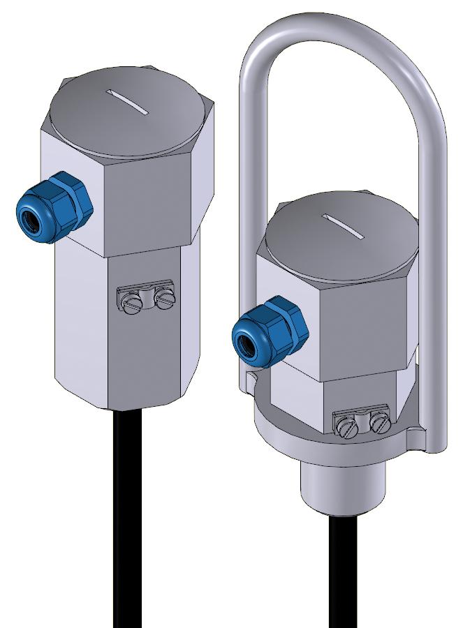
3 GWSL1100/2100, GWML3100 Grain Watch Sensor Cables 1. General description The Grain Watch Temperature Monitoring System is a set of components used to monitor and supervise the temperature in grain storage facilities. The temperature is an instant indicator for all biological activity in the stored grain. Increased temperature reveals biological decomposition, mold, insect hatching and pests. Temperature measurement is done with temperature sensor cables and components that connect the sensor cables into a network with a single point of access. The temperatures can either be sampled manually with hand held portable instruments or be constantly supervised and logged with a stationary computer. The environment, which some of the components of the Grain Watch Temperature Monitoring System are designed to operate in, can be classified as a hazardous area due to the presence of combustible dust. Electrical and mechanical equipment operating in this area has to be explosion and fire protected and separated from equipment in the nonhazardous area in order to be safe. The explosion and fire protection of the Grain Watch Temperature Monitoring System is realized using Intrinsic safety - id and dust ignition protection by enclosure td. The temperature sensor cables GWSL1100/2100 and the humidity sensor cable GWML3100 are the sensors in the Grain Watch Temperature Monitoring System which can contain up to 48 temperature sensors or 26 humidity sensors. The sensor cable has sensors evenly mounted, inside a protective, steel reinforced conduit cable, at intervals of 2-3 meters over the entire length of the cable. It is designed to be suspended in the ceiling of the silo, hanging down into the stored grain and thereby being able to measure the temperature of the grain throughout the entire height of the silo. 2. Before Use 2.1 Important safety precautions The GWSL1100/2100 is intended for operation in the presence of combustible dust. This manual describes important points of caution regarding installation, connection and basic maintenance procedures. Please read this manual carefully before installing and operating the product. o Verify that the operating atmosphere of the GWSL1100/2100 and GWML3100 is consistent with the appropriate hazardous locations certifications. o Verify that the environmental temperature is within the specifications of the GWSL1100/2100 and GWML3100. o Make sure all local legislative requirements regarding electrical installation, authorization, Ex and possibly other requirements comply with the specifications of the Grain Watch Temperature Monitoring System. o Make sure only qualified personnel perform the installation. 1
4 3. Safety certification and features 3.1 Certification label information The certification information is shown on a label placed on the top housing of the sensor cable. GWSL1100-XX Serial No: YYYYWWNNN IECEx TUN X Ex ia IIIC T850C TÜV 10 ATEX X II 1D Ex ia IIIC T85 C -20 C Ta +50 C U:5V I:3mA P:15mW Ui:8V Ii:300mA Pi:500mW Ci:90nF Li:0H Li/Ri:30µH/W AB Liros Electronic, Box 9124, S Malmö, SWEDEN GWSL2100-XX Serial No: YYYYWWNNN IECEx TUN X Ex ia IIIC T850C TÜV 10 ATEX X II 1D EX ia IIIC T85 C -20 C Ta +50 C U:5V I:3mA P:15mW Ui:8V Ii:300mA Pi:500mW Ci:90nF Li:0H Li/Ri:30µH/W AB Liros Electronic, Box 9124, S Malmö, SWEDEN GWML3100-XX Serial No: YYYYWWNNN IECEx TUN X Ex ia IIIC T850C 0044 TÜV 10 ATEX X II 1D Ex ia IIIC T850C -20 C Ta +50 C U:5V I:5mA P:25mW Ui:8V Ii:300mA Pi:500mW Ci:3,0µF Li:0H Li/Ri:30µH/W 3.2 Safety approvals IECEx Type Examination Certificate: TUN X ATEX EC-Type Examination Certificate: TÜV 10 ATEX X o EN :2009 / IEC :2007, Explosive atmospheres Part 0: Equipment General requirements. o EN :2006 / IEC :2005, Electrical apparatus for use in the presence of combustible dust Part 11: Protection by intrinsic safety id. The GWSL1100/2100 and the GWML3100 are designed to meet the following ex protection methods: IECEx marking: Ex ia IIIC T85 C ATEX marking: II 1D Ex ia IIIC T85 C AB Liros Electronic, Box 9124, S Malmö, SWEDEN With the following nominal and safety data for GWSL1100/2100: The manufactured year is identified by the serial number in the form YYYY WWNNN, where YYYY is the year, WW is the week number and NNN is the batch serial number. Serial No means that the unit is no. 10 of the batch manufactured in week 5, year The certification label may not be removed C Ta +50 C U:5V I:3mA P:15mW Ui:8.0V Ii:300mA Pi:500mW Ci:90nF Li:0H Li/Ri:30µH/Ω And the following nominal and safety data for GWML3100: -20 C Ta +50 C U:5V I:5mA P:25mW Ui:8.0V Ii:300mA Pi:500mW Ci:3,0µF Li:0H Li/Ri:30µH/Ω o It is an intrinsically safe component that can be installed in hazardous locations with atmosphere containing combustible dust classified as Zone 20, 21 and 22. It has to be connected to an associated In addition to the Ex certification information, it shows the product model number, variant number, serial number, year of manufacture, intrinsic safety parameters, operating parameters and LIROS Electronic name and location.
5 apparatus compatible with the intrinsic safety parameters: Ui:8.0V, Ii:300mA and Pi:500mW. It adds 90nF (GWSL1100/2100) or 3.0µF (GWML3100) and 0H to the total capacitance and inductance of the intrinsically safe circuit. It has an Li/Ri ratio of 30µH/Ω o The surface of the enclosure can reach a maximum temperature of 85 C when operated in an ambient temperature between -20 C to +50 C. This has not been determined with a dust layer test or dust immersion test. o Nominal values for U, I and P are 5V, 3mA and 15mW (GWSL1100/2100) or 5mA and 25mW (GWML3100). The GWSL1100/2100 and GWML3100 are also tested to meet the Council Directive 2004/108/EC Electromagnetic Compatibility (EMC) by applying the following standards: o EN/IEC :2001, Electromagnetic Compatibility (EMC) Part 6-2: Generic Standards Immunity for Industrial Environments. o EN/IEC :2001, Electromagnetic Compatibility (EMC) Part 6-3: Generic Standards Emission standard for residential, commercial and light-industrial environments. 3.3 Variants The XX after the model number in the labels above identifies the variant for the sensor cable. The difference between the variants is that the top housing is made for different types of suspension methods in the silo. The sensor cables can be mounted with one of the following methods. Suspension in loop: The sensor cable is hanged inside the top of the silo in a loop mounted on the sensor cable housing. Floor well mount: The sensor cable is mounted through a floor well in the top of the silo. This is used for concrete silos. Pipe mount: The sensor cable is mounted through a pipe on top of the silo. This is used for steel bin silos. Pipe mount with loop: This is the same as the pipe mounted sensor cable with a loop mounted on the sensor cable top housing. The sensor cable can then either be suspended in the loop or mounted through a pipe. Short floor well mount: The sensor cable is mounted through a floor well in the top of the silo. This is mainly used for concrete silos where there already are floor wells with limited space Variants for GWSL1100 GWSL Floor well mount GWSL Pipe mount GWSL Short floor well mount The GWSL can be fitted with an external suspension loop which enables it to be hanged inside the silo Variants for GWSL2100 GWSL GWSL GWSL GWSL GWSL Variants for GWML3100 GWML GWML GWML GWML GWML Floor well mount Pipe mount Pipe mount with loop Short floor well mount Suspension loop The GWML has a sensor mounted in a filter in the top housing in order to be able to measure the moisture conditions in the head space above the grain in the silo. Suspension loop Floor well mount Pipe mount Pipe mount with loop Short floor well mount 3
6 4. Installation 4.1 Installation diagram Installation diagram for GWSL1100/2100 and GWML3100 B/+ A/COM Unspecified apparatus (*6) RS485 GWAB11-01: 230V / 50Hz GWAB11-02: 115V / 60Hz Safe - Unclassified Area L COM CN5 A/B/+ CN6 COM N GWAB11 (*5) A/B/+ CN4 SW1 SW2 (*5) Intrinsically safe terminals DNET4 NET4 DNET3 NET3 NET2 DNET2 Intrinsically safe wiring DNET1 NET1 GWNET11 (*5) CN2 SW1 CN1 +5VNET DNET CN6 Hazardous Area Zone 21 or 22 GWSL1100/2100 or GWML3100 (*1) DL DL 4 (*3) Enclosure earth connection (*4) Hazardous Area Zone 20, 21 or 22 GWSL1100/2100 (*2) DL3 CN5 CN4 DL2 DL1 CN3 DL4 +5VNET DNET
7 4.2 Components connected to the safe circuit The installation diagram shows a typical installation using a GWAB11 as the intrinsically safe associated apparatus, i.e. the barrier and a GWNET11 to extend the number of sensor cable inputs in the GWAB11. Notes: *1: A sensor cable which can be any of the types GWSL1100/2100 or GWML3100. *2: A sensor cable which can be of the types GWSL1100 or GWSL2100. The humidity sensor cable GWML3100 can not be connected to a GWNET11. *3: and DL is marked only by the color of the wires. is white or gray. DL is white or gray with a red stripe. *4: In order to prevent an ignition hazard caused by electrostatic build-up and subsequent propagating-brush-discharges, lightning or other electrical faults, the top housing of the sensor cable has to be grounded to earth. The surface of the protective conduit cable is electrically conductive in order to discharge electrostatic charges. It is essential that the sensor cable is connected to a local earthed ground potential with as short wires as possible. *5: Components part of the Grain Watch Temperature Monitoring system. Note that it is only the sensor cables that can be placed in hazardous locations Zone 20. For installation information regarding the other components, see the individual installation manuals for the respective component. *6: Apparatus that is unspecified except that it must not, under normal or abnormal conditions, be supplied from, nor contain, a source of voltage with respect to earth, in excess of 250V r.m.s. This is normally a host computer which communicates with the GWAB11s through the RS485 interface. The sensor cables are intrinsically safe components that can be installed in atmosphere containing combustible dust. In order to not invalidate the safety, the sensor cables must be connected to an associated apparatus, i.e. a safety barrier. The entity parameters of the intrinsically safe components and the wiring connected to the intrinsically safe circuit have to match the parameters of the safety barrier in the associated apparatus, e.g. a GWAB11 or GWAB12. All the intrinsically safe components in the Grain Watch Temperature Monitoring System, including the sensor cables are designed to be compatible with the safety barrier in the GWAB11 and GWAB12. These parameters include Uo/Ui, Io/Ii, Po/Pi and Co/Ci. 4.3 Wiring Wiring has to be done in accordance with intrinsic safety standards. Wiring with nonintrinsically safe circuits must be separated from wiring with intrinsically safe circuits. Wires with separate intrinsically safe circuits must also be separated from each other, e.g. wiring from two separate GWABs. Separate conduits, cable trays etc. can be used to keep the wiring separate. Wiring to separate sensor cable inputs in one GWAB are part of the same intrinsically safe circuit and does not have to be separated. Wiring to all sensor cables connected to all GWNET11s for one GWAB is also part of the same intrinsically safe circuit. Intrinsically safe wiring must be clearly identified, preferably by using a light blue color, as long as no other wiring is light blue. If light blue is used on nonintrinsically safe wiring, the intrinsically 5
8 gland is fully engaged. For extreme conditions there is also a hood available that protects the top housing from the outside weather. For improved EMC performances it is recommended that wiring of the safe circuit is done with a shielded cable. Since current flowing in earth loops in the hazardous area can invalidate the safety, the shields have to be connected in one end of the cable only. Cables connected to the sensor cables, through the plastic cable gland shall NOT have its shield terminated since it already is terminated in the other end in the GWNET or the GWAB. The shield for the connecting cable has to be insulated from the circuits and the metallic top housing in the GWSL1100/2100 and the GWML3100. The insulation must be done with shrink tube or equivalent and be done so that the shield is insulated inside the plastic cable gland. The insert seal in the cable gland shall only cover the cable itself and not the shrink tube. The insulation between the shield and the earthed top housing and the circuits inside the housing has to be capable of withstanding an r.m.s. a.c. test voltage of at least 500V. Cable gland insert seal Shrink tube Shield Cable Plastic cable gland The shield, at any end of the cable, MUST NEVER, under any circumstance, be connected to or any other terminal in the sensor cables, the GWNET11 or the GWAB11/12. For sensor cables that have the top housing located outside, e.g. pipe mounted variants, wiring should be done so that the incoming cable is connected from below in order to minimize risk of rain water flowing into the housing on a cable connected from above. In this case it is also important to make sure that the top blanking element, the lid, and the cable Setup In order for the host system to be able to acquire the data from the sensor cables, each sensor cable has to be uniquely identified with an address in the sensor cable network. This is not done in the sensor cable itself; instead it is done with switches in the GWAB11/12 and the GWNET11. This has the advantage that sensor cables can be swapped or replaced without reconfiguration of the host software. Part of the address for a sensor cable is determined by which input in the GWNET11 or the GWAB11/12 that the sensor cable is connected to which means that it is important to use the correct input and not change inputs once the system is configured and operating. When Liros TMS PC software is used, it is always accompanied with a CD that contains the software pre configured and with a binder containing schematic diagrams and component overviews with information about how the switches in the GWAB11/12s and GWNET11s should be set and at what input in the GWAB11/12s or the GWNET11s the sensor cables should be connected to. For a successful installation these instructions must always be followed exactly. If the sensor cables are not connected according to the instructions in the binder or the switches are not set according to the instructions, the software will not work and the temperatures for a sensor cable may not show up at all or it may be displayed as temperatures for another sensor cable. safe wiring can be marked by other means, such as tagging. This must be visible after installation.
9 4.5 Checklist before applying power Make sure to check that: o The GWSL1100/2100 or GWML3100 and all components in the system operating in the hazardous area are connected to an appropriate earth connection. o All sensor cables are connected to the correct inputs in the GWAB11/12 or GWNET11 in accordance with the connection diagrams. o Wiring is done according to the connection diagrams and intrinsic safety standards. o The shields for all cables in the hazardous locations are connected at one end only and that they are connected to the enclosure or sensor cable housing using the metal EMC cable glands. 5. Maintenance and repair 5.1 Periodic maintenance The unit should periodically be cleaned from excessive layers of dust. Check integrity of earth grounding and electrical connections at periodical intervals. 5.2 Repair The GWSL1100/2100 and the GWML3100 are not field repairable and contains no replaceable parts. Any attempt to modify or repair this unit will void the warranty and the safety certification. If repair is necessary, return the unit to the manufacturer. o The top blanking element in the sensor cable is fully engaged and the cable glands are tightened accordingly, especially in sensor cables where the top housing is located outside the silo. 7
10 6. GWNET11 Specifications 6.1 GWSL1100/2100 and GWML3100 Specifications U - Nominal voltage I - Nominal current P - Nominal power Ui Maximum voltage that can be applied to any terminal without invalidating safety Ii - Maximum current that can be applied to any terminal without invalidating safety Pi - Maximum power that can be applied to any terminal without invalidating safety Ci Maximum unprotected internal capacitance Li/Ri internal inductance to resistance ratio Maximum surface temperature Operating temperature Certifications 300mA 500mW GWSL1100/2100: 90nF GWML3100: 3.0µF 30µH/Ω 85 C -20 C +50 C IECEx: TUN X ATEX: TÜV 10 ATEX X IECEx: Ex ia IIIC T85 C ATEX: II 1D Ex ia IIIC T85 C Marking 5V GWSL1100/2100: 3mA GWML3100: 5mA GWSL1100/2100: 15mW GWNL3100:25mW 8.0V 8
11
12 GRAIN-WATCH Silo Temperature Monitoring AB Liros Electronic, Box 9124, S Malmö, SWEDEN Tel: , Fax: ,
EU DECLARATION OF CONFORMITY
 The Low Voltage Directive (LVD) 2014/35/EU and Electromagnetic Compatibility (EMC) Directive 2014/30/EU. Capacitive level sensor DLS 27N(T) Capacitive level sensor type DLS 27N(T) is designed to bistable
OilSET Installation and Operating Instructions. Oil Separator Alarm Device with SET/DM3AL sensor
 Labkotec UK Ltd Adminicle House 1 Lumb Lane Audenshaw Manchester M34 5WH GREAT BRITAIN Tel: 0844 3350 477 Fax: 0161 4281 179 E-mail: info@labkotec.co.uk 10.8.2012 Internet: www.labkotec.co.uk 1/13 OilSET-1000
SET Installation and Operating Instructions. Level switch for one sensor
 Labkotec Oy Myllyhaantie 6 FI-33960 PIRKKALA FINLAND Tel.: +358 29 006 260 Fax: +358 29 006 1260 7.11.2013 Internet: www.labkotec.fi 1/14 SET-1000 Level switch for one sensor Copyright 2013 Labkotec Oy
INSTRUCTION MANUAL IS-mB1 Minialite Intrinsically Safe Round LED Beacon
 INSTRUCTION MANUAL Minialite Intrinsically Safe Round LED This instruction sheet describes installations which conform to EN60079:Part14:2008 Electrical Installation in Hazardous Areas. When designing
OilSET Installation and Operating Instructions. Oil Separator Alarm Device
 Labkotec Oy Myllyhaantie 6 FI-33960 PIRKKALA FINLAND Tel: +358 29 006 260 Fax: +358 29 006 1260 18.11.2010 Internet: www.labkotec.fi 1/10 OilSET-1000 Oil Separator Alarm Device Copyright 2010 Labkotec
YTA Series Temperature Transmitters [Style: S3] EN :2006, -11:2007, -26:2007. Supply circuit: Ui=30 V, Ii=165 ma,
![YTA Series Temperature Transmitters [Style: S3] EN :2006, -11:2007, -26:2007. Supply circuit: Ui=30 V, Ii=165 ma,](/thumbs/89/98785336.jpg "YTA Series Temperature Transmitters [Style: S3] EN :2006, -11:2007, -26:2007. Supply circuit: Ui=30 V, Ii=165 ma,") User s Manual YTA Series Temperature Transmitters [Style: S3] Manual Change No. 10-008 Please use the attached sheets in the following manuals when the product is with /KU2 option and EN60000 Series based
User s Manual YTA Series Temperature Transmitters [Style: S3] Manual Change No. 10-008 Please use the attached sheets in the following manuals when the product is with /KU2 option and EN60000 Series based
DB5 Intrinsically Safe Sounder Type DB-5
 Operating Instructions RTK Instruments Limited DB5 Intrinsically Safe Sounder Type DB-5 Description The DB5 Sounder is a strong, lightweight warning sounder, CENELEC certified to Ex II 1G EExia IIC T4
AND INSTALLATION MANUAL
 Labkotec Oy Myllyhaantie 6 FI-33960 PIRKKALA FINLAND Tel. +358 29 006 260 Fax +358 29 006 1260 Internet: www.labkotec.fi 10.10.2013 SET/DM3AL Level sensor OPERATION AND INSTALLATION MANUAL 1(5) SYMBOLS
4) Intrinsic Safety Certification
 Intrinsic Safety Certification") INSTRUCTION MANUAL Minialert Intrinsically Safe Round Combined Unit Section Volume Control Tone Generator S2 S3 Tone Selection Switches Fig 1 Simplified block diagram The combined unit is CE marked for
INSTRUCTION MANUAL Minialert Intrinsically Safe Round Combined Unit Section Volume Control Tone Generator S2 S3 Tone Selection Switches Fig 1 Simplified block diagram The combined unit is CE marked for
IECEx Certificate of Conformity
 INTERNATIONAL ELECTROTECHNICAL COMMISSION IEC Certification Scheme for Explosive Atmospheres for rules and details of the IECEx Scheme visit www.iecex.com Certificate No. : Status: Date of Issue: Applicant:
Intrinsically Safe, NEMA 4, Type 4X, IP67 Loop-Powered Meter
 PD685 Intrinsically Safe, NEMA 4, Type 4X, IP67 Loop-Powered Meter Actual Size Digits C US Intrinsically Safe 3½ Digits LARGE DISPLAY NEMA 4, Type 4X, IP67 Loop-Powered Field-Mount Process Meter 4-20 ma
SET-2000 Oil/Sludge 12 VDC
 Labkotec Oy Myllyhaantie 6 FI-33960 PIRKKALA FINLAND Tel: + 358 29 006 260 Fax: + 358 29 006 1260 12.2.2015 Internet: www.labkotec.fi 1/14 SET-2000 Oil/Sludge 12 VDC Alarm Device for Oil Separators with
Inductive slot sensor
 0102 Model Number Features 2 mm slot width Technical Data specifications Switching function Normally closed (NC) Output type NAMUR Slot width 2 mm Depth of immersion (lateral) 5... 7 mm, typ. 6 mm Output
SET-2000 Hi Level/Oil
 Labkotec Oy Labkotie 1 FI-36240 KANGASALA FINLAND Tel: + 358 29 006 260 Fax: + 358 29 006 1260 13.03.2008 Internet: www.labkotec.fi Alarm Device for Oil Separators Copyright 2008 Labkotec Oy We reserve
INSTRUCTION MANUAL. SIL 3 - SIL 2 IIB Group Power Supply for Hazardous Area Equipment DIN-Rail Model PSD1001C PSD1001C
 PSD1001C INSTRUCTION MANUAL SIL 3 SIL 2 IIB Group Power Supply for Hazardous Area Equipment DINRail Model PSD1001C PSD1001C SIL 3 SIL 2 IIB Group Power Supply for hazardous Area Equipment ISM006510 General
Safety instructions VEGADIF DF65.GX*****H/Z/P/F***** IECEx BVS
 Safety instructions VEGADIF DF65.GX*****H/Z/P/F***** IECEx BVS 10.0008 Ex td A20, A20/21, A20/22, A21 IP66 T 0044 37675 Contents 1 Area of applicability 3 2 General information 3 2.1 Zone 20 instruments
OPTIBAR DP 7060 Supplementary Instructions
 OPTIBAR DP 7060 Supplementary Instructions Differential pressure transmitter Category ATEX II 1/2G, 2G Ex db ia IIC T6...T1 Ga/Gb, Gb IECEx Ex db ia IIC T6...T1 Ga/Gb, Gb Housing Aluminium: Single chamber,
INSTRUCTION MANUAL (ATEX)
") INSTRUCTION MANUAL (ATEX) ISmA1M Minialarm Intrinsically Safe Round ISmA1M Volume Control Tone Generator S3 Tone Selection Switches Fig 1 Simplified block diagram The ISmA1M sounder is CE marked for compliance
INSTRUCTION MANUAL (ATEX) ISmA1M Minialarm Intrinsically Safe Round ISmA1M Volume Control Tone Generator S3 Tone Selection Switches Fig 1 Simplified block diagram The ISmA1M sounder is CE marked for compliance
SET-2000 Oil/Sludge. Alarm Device for Oil Separators. Installation and Operating Instructions
 SET-000 Oil/Sludge Alarm Device for Oil Separators Copyright 007 Labkotec Oy We reserve the right for changes without notice TABLE OF CONTENTS GENERAL... INSTALLATION... 4. SET-000 Oil/Sludge Control Unit...
Annubar Flowmeter Series
 Reference Manual Appendix B Approvals Annubar Flowmeter Series Hazardous Locations Installations.................. page B-1 Rosemount 3051SFA Product Certifications.......... page B-1 Rosemount 3095MFA
User s Manual YTA610 and YTA710 NEPSI Certification
 User s Manual YTA60 and YTA70 NEPSI Certification [Option code: /NS, /NS5 and /NF] st Edition . INTRODUCTION Thank you for purchasing the YTA60 and YTA70 Temperature transmitters. This manual contains
Technical Data. Dimensions
 0102 Model Number Features 8 mm non-flush Stainless steel housing Usable up to SIL2 acc. to IEC 61508 Technical Data specifications Switching element function NAMUR, NC Rated operating distance s n 8 mm
Technical Data. General specifications. Rated operating distance s n 5 mm
 0102 Model Number Features 5 mm non-flush Usable up to SIL 2 acc. to IEC 61508 Technical Data specifications Switching function Normally closed (NC) Output type NAMUR Rated operating distance s n 5 mm
OilSET-1000 (12 VDC)
") Labkotec Oy Myllyhaantie 6 FI-33960 PIRKKALA FINLAND Tel: +358 29 006 260 Fax: +358 29 006 1260 Internet: www.labkotec.fi 20.03.2009 1/11 OilSET-1000 (12 VDC) Oil Separator Alarm Device Copyright 2009
Labkotec Oy Myllyhaantie 6 FI-33960 PIRKKALA FINLAND Tel: +358 29 006 260 Fax: +358 29 006 1260 Internet: www.labkotec.fi 20.03.2009 1/11 OilSET-1000 (12 VDC) Oil Separator Alarm Device Copyright 2009
IECEx Certificate. INTERNATIONAL ELECTROTECHNICAL COMMISSION IEC Certification Scheme for Explosive Atmospheres
 INTERNATIONAL ELECTROTECHNICAL COMMISSION IEC Certification Scheme for Explosive Atmospheres for rules and details of the IECEx Scheme visit www.iecex.com Certificate No.: Certificate history: Status:
Technical Data. Dimensions
 0102 Model Number Features 5 mm flush Usable up to SIL2 acc. to IEC 61508 Accessories EXG-18 Quick mounting bracket with dead stop BF 18 Mounting flange, 18 mm Technical Data specifications Switching element
OPTIBAR P 1010/2010 C Supplementary instructions
 OPTIBAR P 1010/2010 C Supplementary instructions Pressure transmitter Equipment category II 1G / Ga, II 1D / Da in protection type intrinsic safety Exi KROHNE CONTENTS OPTIBAR P 1010/2010 C 1 Safety instructions
Technical Data. General specifications Switching element function Rated operating distance s n 4 mm
 0102 Model Number Features 4 mm non-flush Accessories BF 12 Mounting flange, 12 mm Technical Data specifications Switching element function NAMUR, NO Rated operating distance s n 4 mm Installation non-flush
Technical Data. General specifications Switching element function DC Dual NC Rated operating distance s n 3 mm
 0102 Model Number Features Direct mounting on standard actuators EC-Type Examination Certificate TÜV99 ATEX 1479X Accessories BT32 BT32XS BT32XAS BT33 BT34 V1-G-N4-5M-PUR Female cordset, M12, 4-pin, NAMUR,
Technical Data. General specifications Switching element function Rated operating distance s n 8 mm
 0102 Model Number Features 8 mm non-flush Usable up to SIL 3 acc. to IEC 61508 Application Danger! In safety-related applications the sensor must be operated with a qualified fail safe interface from Pepperl+Fuchs,
VERSAFLOW VORTEX Supplementary instructions
 VERSAFLOW VORTEX Supplementary instructions Vortex flowmeter Equipment category II 2G CONTENTS VERSAFLOW VORTEX 1 Safety instructions 3 1.1 General notes... 3 1.2 EC conformity... 3 1.3 Approval according
RADAR LEVEL GAUGE SPECIAL SAFETY INSTRUCTION
 Special Safety Instruction en RADAR LEVEL GAUGE SPECIAL SAFETY INSTRUCTION Contents TankRadar Pro European ATEX Directive Information............................... 2 ATEX marking and Ex Certification
Technical Data. General specifications Switching element function Rated operating distance s n 5 mm
 0102 Model Number Features 5 mm non-flush Usable up to SIL2 acc. to IEC 61508 Technical Data specifications Switching element function NAMUR, NC Rated operating distance s n 5 mm Installation non-flush
MAINS KLARGESTER SEPARATOR ALARM INSTALLATION & OPERATIONS MANUAL
 MAINS KLARGESTER SEPARATOR ALARM INSTALLATION & OPERATIONS MANUAL Contents IMPORTANT... 3 General Description... 4 General Operation... 4 Changing Factory Settings... 4 Alarm Type... 4 Check Interval...
14300 MAINS SEPARATOR ALARM MANUAL
 Conder Environmental Solutions 14300 MAINS SEPARATOR ALARM MANUAL Separator and Alarm provided by: Alarm Installation, Commissioning & Servicing Support Please contact: www.envirotank.com.au www.envirotank.co.nz
Rosemount 3490 Series
 Product Data Sheet July 2014 00813-0100-4841, Rev DA Rosemount 3490 Series 4 20 ma + HART Compatible Controller Field mounted controller with integral multi-function LCD and keypad Tough weatherproof wall
IECEx Certificate of Conformity
 Page 1 of 10 IECEx Certificate of Conformity INTERNATIONAL ELECTROTECHNICAL COMMISSION IEC Certification Scheme for Explosive Atmospheres for rules and details of the IECEx Scheme visit www.iecex.com Certificate
Supplementary Installation and Operating Instructions. Category II2G
 Supplementary Installation and Operating Instructions Flap-type Flow Meter Category II2G 2 Contents 1. General safety directions...3 2. Main safety-relevant characteristics...4 2.1. Category / Zone...4
Rosemount 3490 Series 4 20 ma + HART Compatible Controller
 00825-0200-4841, Rev AB Rosemount 3490 Series 4 20 ma + HART Compatible Controller Failure to follow safe installation guidelines could result in death or serious injury The Rosemount 3490 Series Control
Technical Data. General specifications Switching element function Rated operating distance s n 5 mm
 0102 Model Number Features 5 mm flush Usable up to SIL 3 acc. to IEC 61508 Application Danger! In safety-related applications the sensor must be operated with a qualified fail safe interface from Pepperl+Fuchs,
Ex Long & Short stroke LPI POSITION TRANSMITTER MKII For linear position measurement in compressors
 Instructions manual Ex Long & Short stroke LPI POSITION TRANSMITTER MKII For linear position measurement in compressors HB Products A/S Bøgekildevej 21 DK8361 Hasselager support@hbproducts.dk www.hbproducts.dk
Installation and Operating Instruction
 Installation and Operating Instruction Automatic Fire Detectors Series 900 Ex (i) 9893 0.00 GB Technical changes reserved! 0 Installation and Operating Instruction Automatic Fire Detectors Series 900 Ex
Tank Gauging System Special Safety Instruction
 Tank Gauging System www.rosemount-tg.com Rosemount TankRadar REX Table of Contents Contents SPECIAL SAFETY INSTRUCTION........................ 1-1 1. GENERAL REQUIREMENTS....................... 1-2 1.1
Additional Operating Instructions SITRANS F. Vortex flowmeters. SITRANS FX330 Ex-i.
 Additional Operating Instructions SITRANS F Vortex flowmeters Ex-i Edition 09/2018 CONTENTS 1 Safety instructions 3 1.1 General notes... 3 1.2 EU conformity... 3 1.3 Approval according to the IECEx scheme...
E2S Datasheet v10a. The IS-mA1 is suitable for all intrinsically safe signalling applications including fire, security and process control.
 E2S Datasheet 1.2.1 v10a ISmA1 ISminialarm The ISmA1 is a compact, 100dB(A) alarm sounder. Approvals include ATEX, IECEx and GOSTR for Zone 0 applications and FM approval for Class I Division 1 and Class
Air Sensor. SAC Ex FCS Ex. Manual ATEX. AQ M-Tech AB
 Air Sensor SAC Ex FCS Ex Manual AQ M-Tech AB ATEX Air Sensor SAC Ex FCS Ex ATEX Certified AQ M-Tech AB Manual version 2.2 February 2017 2 Air Sensor Manual for SAC Ex and FCS Ex Table of contents 1. Manufacturer
MANUAL Oil Level Sensor
 PROCESS AUTOMATION MANUAL Oil Level Sensor KVF-104-PF ISO9001 0102 With regard to the supply of products, the current issue of the following document is applicable: The General Terms of Delivery for Products
Safety instructions VEGADIS DIS61.CC/O** VEGADIS DIS81.CC/O******
 Safety instructions VEGADIS DIS61.CC/O** VEGADIS DIS81.CC/O****** CSA 14.2662675 Ex ia IIC T6 Ga, Gb 0044 Document ID: 48924 Contents 1 Area of applicability... 3 2 General information... 3 3 Technical
Fixed Gas Detection System/Meridian CERTIFICATION
 The marking shall include 2 Wire Aluminum Transmitter 3/4 Wire Aluminum Transmitter 2 Wire Stainless Steel Transmitter (PN: 096-3521) (PN: 096-3522) (PN: 096-3525) Ex db [ia Ga] IIC T4 Gb Ex db [ia Ga]
D SYSTEM CONTROL DWG. APPROVED BY. OrCAD 6 ROSEMOUNT 2410
 FIELDBUS INTRINSICALLY SAFE CONCEPT (FISCO) APPROVAL FISCO allows interconnection of intrinsically safe apparatus to associated apparatus not specially examined in such combination. The criteria for interconnection
Earth-Rite II PLUS Static Earthing System
 READ MANUAL BEFORE COMMENCING WITH INSTALLATION EN Earth-Rite II PLUS Static Earthing System P1 PLUS - DC Supply Installation & Operating Instructions The safety of any system incorporating the equipment
Technical Data. Dimensions
 0102 Model Number Features 15 mm non-flush Technical Data specifications Switching element function NAMUR, NC Rated operating distance s n 15 mm Installation non-flush Assured operating distance s a 0...
DSF xx10.xx xhv Ex-Atex Hall Effect Single Channel Speed Sensor
 Product ID Type # Product # Drawing # DSF 1210.00 SHV Ex-atex (2m) 374Z-05066 110428F1 DSF 1210.00 SHV Ex-atex (5m) 374Z-05176 110428F1 DSF 1210.00 SHV Ex-atex (10m) 374Z-05590 110428F1 DSF 1410.00 SHV
A Characteristics for Electrical Equipment integrated Into SLR Enclosure - Intrinsically Safe Reference Document
 A190325 Characteristics for Electrical Equipment integrated Into SLR Enclosure - Intrinsically Safe Reference Document CONTENTS INTRODUCTION 1. DUAL CERTIFIED COMPONENTS 1.1 Simple Apparatus Switches For
INSTRUCTION MANUAL (ATEX / IECEx)
") INSTRUCTION MANUAL (ATEX / IECEx) BExS110D and BExS110D-R Sounder For use in Flammable Gas and Dust Atmospheres BExS110D BExS110D-R 1) Warnings DO NOT OPEN WHEN AN EXPLOSIVE ATMOSPHERE IS PRESENT DO NOT
INSTRUCTION MANUAL (ATEX / IECEx) BExS110D and BExS110D-R Sounder For use in Flammable Gas and Dust Atmospheres BExS110D BExS110D-R 1) Warnings DO NOT OPEN WHEN AN EXPLOSIVE ATMOSPHERE IS PRESENT DO NOT
User s Manual. EJA Series Differential Pressure and Pressure Transmitters Manual Change No Yokogawa Electric Corporation
 User s Manual EJA Series Differential Pressure and Pressure Transmitters Manual Change No. 12-004 For the models EJA and EJA-A series with option code /KF21, /KU21, /KU22 or /KN26, please use this manual
PESO. Temperature sensors with cables Thermocouples and RTD temperature probes ATEX I, e, t For use in areas with an explosion hazard
 Temperature sensors with cables Thermocouples and RTD temperature probes ATEX I, e, t For use in areas with an explosion hazard Persons concerned: Experienced professional electricians as per EU Directive
DSF xx15.xx xhv Ex-Atex Ex-Atex Certified Two wire Hall Effect Speed Sensor
 DSF xx15.xx xhv Ex-Atex Product ID Type # Product # Drawing # DSF 1215.01 SHV Ex-atex (5m) 304Z-05197 113216 DSF 1415.01 AHV Ex-atex S148 304Z-05256 113351 DSF 1615.01 SHV Ex-atex (5m) 304Z-05196 113214
Additional Operating Instructions SITRANS F. Vortex flowmeters. SITRANS FX330 Ex-nA.
 Additional Operating Instructions SITRANS F Vortex flowmeters Ex-nA Edition 08/207 CONTENTS Safety instructions 3. General notes... 3.2 EU conformity... 3.3 Approval according to the IECEx scheme... 3.4
Additional Operating Instructions SITRANS F. Vortex flowmeters. SITRANS FX330 Ex-d.
 Additional Operating Instructions SITRANS F Vortex flowmeters Ex-d Edition 09/208 CONTENTS Safety instructions 3. General notes... 3.2 EU conformity... 3.3 Approval according to the IECEx scheme... 3.4
RT FLOW RATE TOTALISER
 Universal Mount Series RT FLOW RATE TOTALISER I N S T R U C T I O N M A N U A L S U P P L E M E N T for I N T R I N S I C A L L Y S A F E F L O W R A T E T O T A L I S E R ATEX & IECEx approvals The name
PEPPERL+FUCHS GmbH
 Comfort series 1.5 mm embeddable M8x1 4 25 16 13 LED Switching element function NAMUR NC Rated operating distance s n 1,5 mm Installation embeddable Assured operating distance s a 0... 1,215 mm Reduction
Universal Tank Alarm Type Installation, Operation & Maintenance
 Universal Tank Alarm Type 14400 Installation, Operation & Maintenance Universal Tank Alarm Type 14400 Contents Declaration of Conformity 3 IMPORTANT 3 General Description 4 General Operation 4 Installation
Declaration of conformity
 File: ATEX Manoswitch DoC 2017-10-20 Rev: 2017-10-20 id: mk Declaration of conformity The products listed in Appendix B, meet the requirements for a simple apparatus given by the standards listed below.
HAWK SULTAN SERIES Sma rt Universa l Level Tra nsmitter And Network. Equipment types:
 Safety instructions 0359 HAWK SULTAN SERIES Sma rt Universa l Level Tra nsmitter And Network ATEX Category 1 GD (A0) Equipment types: AWRT series Sultan Remote Transducer AWR series Sultan Remote Electronics
OOH740-A9-Ex Multi-sensor fire detector
 OOH740-A9-Ex Multi-sensor fire detector ASAtechnology TM For potentially explosive areas Cerberus PRO Collective Signal processing with ASAtechnology Multiple protocol detector (collective/c-net-ex) Event-controlled
Manual Power relay SR853
 Manual Power relay SR853 Product types SR853.8.x.x, Rev. 1 SR853 manual page2 The symbols WARNING, CAUTION, NOTE This symbol warns of a serious hazard. Failure to observe this warning may result in death
INSTRUCTION MANUAL. SIL 2 Load Cell/Strain Gauge Bridge Isolating Converter DIN-Rail Power Bus and Termination Board Model D5264S D5264S
 D5264S INSTRUCTION MANUAL SIL 2 Load Cell/Strain Gauge Bridge Isolating Converter DIN-Rail Power Bus and Termination Board Model D5264S Characteristics General Description: The single channel DIN Rail
OSA 3. Level alarm for oil separator. Afriso Ema AB. Kilvägen 2 SE Arlöv Sweden T +46-(0) F +46-(0)
 F +46-(0)") Level alarm for oil separator CONTENTS: Functional description... 2 Component parts... 3 Spare parts... 5 Safety regulations... 6 Checklist... 7 Installation... 8 Commissioning... 11 Operation... 14 Maintenance...
Level alarm for oil separator CONTENTS: Functional description... 2 Component parts... 3 Spare parts... 5 Safety regulations... 6 Checklist... 7 Installation... 8 Commissioning... 11 Operation... 14 Maintenance...
OOH740-A9-Ex Multisensor fire detector
 OOH740-A9-Ex Multisensor fire detector ASAtechnology TM For potentially explosive areas Cerberus PRO Collective Signal processing with ASAtechnology Multiple protocol detector (collective/c-net-ex) Event-controlled
Technical Data. Dimensions
 0102 Model Number Features Comfort series 50 mm non-flush Technical Data specifications Switching element function NAMUR, NC Rated operating distance s n 50 mm Installation non-flush Output polarity NAMUR
Solar Separator Alarm Type Installation, Operation & Maintenance
 Solar Separator Alarm Type 14007 Installation, Operation & Maintenance Solar Separator Alarm Type 14007 Contents Declaration of Conformity 3 Important 3 General Description 3 General Operation 3 Changing
E2S Datasheet v10a
 E2S Datasheet 1.2.3 v10a ISmC1 ISminialert The ISmC1 is a compact combined 100dB(A) alarm sounder and L.E.D. beacon only one Zener barrier or galvanic isolator required to run both sounder & beacon or
Operating Instructions
 Important information: These instructions contain safety information, read and follow them carefully. Dialight will not accept any responsibility for injury, damage or loss which may occur due to incorrect
BA334D Intrinsically safe Externally powered pulse input field mounting rate totaliser Issue 13
 TR Automatyka Sp. z o. o. Tel. (+48 022) 886 10 16 www.trautomatyka.pl ul. Lechicka 14 ; 02-156 Warszawa Fax. (+48 022) 846 50 37 biuro@trautomatyka.pl BA334D Intrinsically safe Externally powered pulse
RFM Series RFM-ISR Barrier. Installation Manual
 PSM INSTRUMENTATION LTD RFM Series RFM-ISR Barrier Installation Manual Issue A Burrell Road Industrial Estate Haywards Heath, West Sussex RH16 1TW, UK Tel: +44 (0)1444 410040 Fax: +44 (0)1444 410121 Http://www.psm-sensors.co.uk
Fisher LCP100 Local Control Panel
 Instruction Manual LCP100 Local Control Panel Fisher LCP100 Local Control Panel Contents Introduction... 1 Scope of Manual... 1 Description... 2 Specifications... 2 Installation... 3 Hazardous Area Classifications
OMC Ex interface unit. Manual. Version 1.2 August Author: Observator Instruments
 OMC-158-2 Ex interface unit Manual Version 1.2 August 2017 Author: Observator Instruments Revisions: 0.1 (October 2016) First issue 0.2 (December 2016) Prototype 0.3 (January 2017) Test release 1.0 (March
OPTIWAVE X500 Supplementary Instructions
 OPTIWAVE X500 Supplementary Instructions OPTIWAVE 3500 C OPTIWAVE 6500 C OPTIWAVE 7500 C Supplementary Instructions for ATEX applications KROHNE CONTENTS OPTIWAVE X500 1 General safety information 4 1.1
Sensor module. Operating instructions. Sensor module, Type 17-51P2-... Document No P2-7D0001 Version: 17 May 2011/Rev. 0
 Sensor module Operating instructions Sensor module, Document No. 11-51P2-7D0001 Version: 17 May 2011/Rev. 0 Operating Instructions Sensor-Module Type: 17-51P2-. Document no.: 11-51P2-7D0001 Version: 17.
Operating Instructions Edition 02/2007
 Operating Instructions Edition 02/2007 Temperature Transmitter 7NG3214 with PROFIBUS PA 7NG3215 with FOUNDATION Fieldbus sitrans Introduction 1 General safety notes 2 SITRANS T Temperature transmitter
Quick Start Guide For the
 A Leader in Level Measurement Quick Start Guide For the Universal IV Lite and Universal IV Pro Model Transmitters 2-Wire RF Admittance / Capacitance Level Measurement System with HART Protocol For Assistance
Operating Manual MS220DA
 ZIEHL industrie elektronik GmbH + Co KG Daimlerstraße 13, D 74523 Schwäbisch Hall + 49 791 504-0, info@ziehl.de, www.ziehl.de Temperature Relays and MINIKA Mains Monitoring Digital Panel Meters MINIPAN
INSTRUCTION MANUAL (ATEX/IECEx/SIL2) BExBG05D-SIL Flameproof Xenon SIL 2 Beacons For use in Flammable Gas and Dust Atmospheres
 BExBG05D-SIL Flameproof Xenon SIL 2 Beacons For use in Flammable Gas and Dust Atmospheres") INSTRUCTION MANUAL (ATEX/IECEx/SIL2) BExBG05D-SIL Flameproof Xenon SIL 2 Beacons For use in Flammable Gas and Dust Atmospheres 1) Introduction The BExBG05D-SIL is a flameproof beacon which is certified
INSTRUCTION MANUAL (ATEX/IECEx/SIL2) BExBG05D-SIL Flameproof Xenon SIL 2 Beacons For use in Flammable Gas and Dust Atmospheres 1) Introduction The BExBG05D-SIL is a flameproof beacon which is certified
SOLAR SEPARATOR ALARM
 SOLAR SEPARATOR ALARM INSTALLATION AND OPERATIONS MANUAL Great British Manufacturing For emergency supply, spill cleanup, disposal, contracting, advice and training. Subject Contents Page Important 3 General
INSTRUCTION & SERVICE MANUAL
 INSTRUCTION & SERVICE MANUAL D2xC1 ALARM HORN AND STROBE For Use In Hazardous Locations 3) Ratings and Markings 3.1 ATEX / IECEx certification The D2xC1 Alarm Horn and Strobe complies with the following
ATM Lighting sp. z o.o
 INSTALLATION AND MAINTENANCE MANUAL FOR EXPLOSIONPROOF LIGHT FITTING EXL390LED Carefully read the instructions before mounting the light fitting. ATM Lighting sp. z o.o., ul. Budowlanych 31, 80-298 Gdańsk,
Rosemount 148 Temperature Transmitter. Quick Start Guide , Rev GA September 2016
 Rosemount 148 Temperature Transmitter 00825-0100-4148, Rev GA NOTICE This guide provides basic guidelines for the Rosemount 148. It does not provide instructions for detailed configuration, diagnostics,
SBEx-4 BISTATE SEPARATOR 1, 2, 3 or 4 channels in rail housing (TS35, 22,5mm width)
") SBEx-4 BISTATE SEPARATOR,, 3 or 4 channels in rail housing (TS3,,mm width) - group I category (M), group II and III category () accompanying device, - intrinsically safe input circuits with ia protection
SBEx-4 BISTATE SEPARATOR,, 3 or 4 channels in rail housing (TS3,,mm width) - group I category (M), group II and III category () accompanying device, - intrinsically safe input circuits with ia protection
Fieldbus Non-Incendive Concept takes FISCO into Zone 2 and Division 2 hazardous areas. Phil Saward
 Foundation Fieldbus End Users Council Australia Inc. 9 Corcoran St Duncraig, WA 6023 P.O.Box Z5546 Perth, WA 6831 AUSTRALIA ABN 60 120 236 370 Fieldbus Non-Incendive Concept takes FISCO into Zone 2 and
FDOOT241-A9-Ex Multisensor fire detector
 FDOOT241-A9-Ex Multisensor fire detector ASAtechnology TM For potentially explosive areas Sinteso Collective Signal processing with ASAtechnology Multiple protocol detector (collective/fdnet-ex) Event-controlled
Local Control Panels for VG9000H LCP9H Series. Installation, Maintenance and Operating Instructions
 Local Control Panels for VG9000H LCP9H Series Installation, Maintenance and Operating Instructions 7 LCP9H 70 en 9/2011 2 7 LCP9H 70 en Table of Contents 1 LCP9H Local Control Panels for VG9000H.. 3 1.1
SITRANS T. SITRANS T Explosion protected temperature sensor. General information. Marking of the degree of protection. Range of uses.
 General information 1 Marking of the degree of protection 2 SITRANS T SITRANS T Explosion protected temperature sensor Operating Instructions Range of uses 3 Installation 4 Assembly and disassembly 5 Commissioning
AM54. Armored Variable Area Flowmeter Series AM54331/32 Series AM54371/72/73/74 Series AM54431/32 Series AM54471/72/73/74
 AM54 Instruction Bulletin North American Installation Addendum Document Number PN25016 Armored Variable Area Flowmeter Series AM54331/32 Series AM54371/72/73/74 Series AM54431/32 Series AM54471/72/73/74
ATM Lighting sp. z o.o
 INSTALLATION AND MAINTENANCE MANUAL FOR EXPLOSIONPROOF LIGHT FITTING EXL210LED Carefully read the instructions before mounting the light fitting. ATM Lighting sp. z o.o., ul. Budowlanych 31, 80-298 Gdańsk,
standards: standards:
 INSTRUCTION MANUAL D2xB1LD2 LED Beacons For use in Hazardous Locations 1) Warnings DO NOT OPEN WHEN AN EXPLOSIVE ATMOSPHERE IS PRESENT DO NOT OPEN WHEN ENERGISED POTENTIAL ELECTROSTATIC CHARGING HAZARD
Page 1 Copyright by the Fieldbus Foundation All rights reserved.
 Page 1 Copyright by the Fieldbus Foundation 1996-2004.. FOUNDATION Fieldbus Application Guide 31,25 kbit/s Intrinsically Safe Systems AG-163 Revision 2.0 This application guide has been prepared to aid
Certificate of Compliance
 FF0002 Certificate of Compliance Certificate: 2792948 Issued to: Siemens Canada Limited 1954 Technology Drive Peterborough, ON K9J 7B1 Canada Attention: Mr. Lee Rogers The products listed below are eligible
PROZESSAUTOMATION. Manual SEGMENT PROTECTOR R-SP-!12. Zone 1 Zone 2 / Div 2 FNICO
 PROZESSAUTOMATION Manual SEGMENT PROTECTOR R-SP-!12 FieldConnex TM Segment Protectors with overloaod protection and short-circuit current limitation for the connection of 12 field devices Zone 1 Zone 2
Intrinsically Safe Solutions
 Intrinsically Safe Solutions INSTALLATION MANUAL 04/12/14 Rev D DOC-01-029 Documentation Feedback Your feedback helps us keep our documentation up to date and accurate. If you have any comments or suggestions