Fire-Cryer. Plus Application Guide APPLICATION GUIDE FIRE EXIT VIMPEX. Shaping Alarm Technology
|
|
|
- Edmund Hunter
- 5 years ago
- Views:
Transcription


1 Fire-Cryer Plus Application Guide APPLICATION GUIDE FIRE EXIT VIMPEX Shaping Alarm Technology
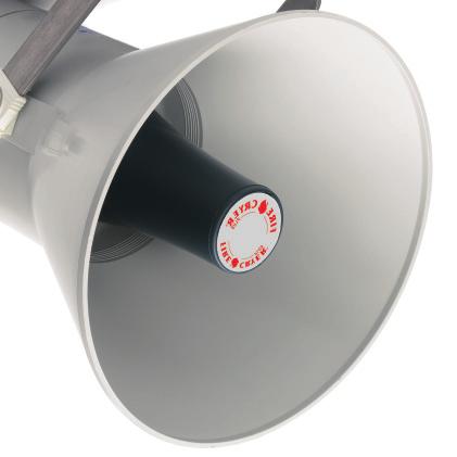
2 Fire-Cryer Plus The Fire-Cryer range of voice sounders was first introduced to the market by Vimpex in The continuing research and development of voice sounders by Vimpex Limited has kept us as the market leader in performance, technical capability and diversity of range and applications. The Fire-Cryer is, in its simplest form, an electronic sounder capable of delivering clear, intelligible and synchronised voice messages and tones. Requiring just 2 wires, a positive and negative, to deliver 24VDC to any one of the Fire- Cryer family of voice sounders it can be retrofitted to existing conventional sounder circuits. The cost savings of using existing wiring can be considerable. With the use of proprietary interfaces the Fire-Cryer can also be easily integrated onto addressable loops and is approved by Hochiki and Apollo. The latest range of Fire-Cryer voice sounders is now capable of holding and broadcasting up to 7 different messages and any number of tones. These messages and tones are programmed into each sounder head. This latest range of Fire-Cryer voice sounders is now known as Fire-Cryer Plus The Fire-Cryer Plus Range of Voice Sounders Mini Fire-Cryer Plus Standard Fire-Cryer Plus Midi Fire-Cryer Plus Maxi Fire-Cryer Plus Animate Fire-Cryer Plus A white base sounder for installation under ceiling mounted detectors. Part Ref. FC3/C A red wall mounted sounder supplied with or without a beacon. Available with a shallow or deep base. Part Ref. FC3/A A high output open area sounder in red. Can be supplied with back box. Part Ref. FC3/B An extra high output industrial sounder, IP67. Part Ref. FC3/D A sounder designed to meet the requirements of low frequency sounders for animals with specific auditory sensitivity levels. Part Ref. FC3/E DIL switches on all sounders can be used to vary the dba output and the beacon output on the FC3/A. Each one of these sounders can be used as a simple single message sounder and any one of the programmed messages can be pre-selected by the user using a DIL switch on the sounder.
.")
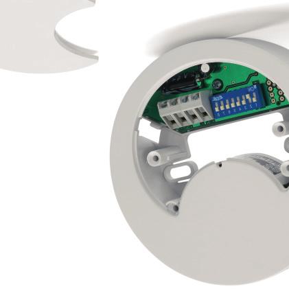
3 Using Multi Message Mode and the Multi Message Switching PCB (MMSP) To use the Fire-Cryer Plus sounders in their multi message mode it is necessary to send commands to the Fire-Cryer Plus sounders to instruct the sounders which of the seven messages they should broadcast. This is achieved by introducing the Multi Message Switching PCB (MMSP). (See Figure 1) Figure 1 The Multi Message Switching PCB (MMSP) has developed into a versatile, expandable and user friendly interface to control up to seven different messages using just two cores. It is capable of handling One out all out scenarios as well as phased evacuation or staged fire alarms. It is as ideally suited to new compact conventional single zone builds, complex networked sites with many zones as well as retrofitting to existing systems. With the addition of interfaces such as the Hochiki CHQ-DSC and the Apollo SCC the Fire-Cryer Plus can be successfully installed on addressable loops. Each MMSP has two 2A sounder circuits which are monitored by the Fire Alarm Control Panel. The MMSP can be supplied separately or within an enclosure, with or without a keypad. The MMSP has six inputs available to trigger the auxiliary messages. These are identified as MA, MB, MC, MD, ME and MF. The primary message, which is known as the DEFAULT message, is usually FIRE or EVACUATE and preceded by an alerting tone chosen by the user. The remaining six messages are know as AUXILLARY messages as any of these will be overridden by the DEFAULT message. Two of the six auxiliary inputs (MA and MB) are monitored providing the opportunity to include panic alarms and terrorist or bomb alerts. These inputs can be triggered by a 470Ω resistor in series with a switch e.g a manual call point. The auxiliary messages MC, MD ME and MF can be activated by introducing a link between their respective inputs and COM. This can be achieved by a relay, key switch, IO unit, call point or similar switch. The MMSP has LED indicators on board for troubleshooting and testing.
 Diagram of FACP MMSP Sounder Circuits or between the loop interface (S/C) and the sounder circuits to the field.")


4 The MMSP is either installed between the sounder circuit outputs of the Fire Alarm Control Panel (FACP) and the sounder circuits to the field. (See Figure 2) Diagram of FACP MMSP Sounder Circuits or between the loop interface (S/C) and the sounder circuits to the field. (See Figure 2) In each of these cases the last device on the sounder circuit should contain an to match the FACP being used. The MMSP in its quiescent state is invisible to the FACP and will monitor the devices on the sounder circuit in its normal manner. Zone Extension PCB (Part Ref. ZEP) A zone extension PCB is also available to seamlessly add an additional 3 zones. Each zone has two sounder circuits rated at 2A each. With the MMSP this provides up to 4 zones or 8 sounder circuits with a total load of 16A. Each ZEP has LED indicators for test and troubleshooting. When the ZEP is attached to the MMSP, all messages, whether fire or auxiliary, are synchronised. If a zone goes to Fire it will change its message immediately, or at the
5 end of the current auxiliary message. If an additional zone goes to Fire then it will broadcast an alarm tone until it synchronises with the zone already in Fire Zone Expansion Many MMSPs can be connected together via an Inter Synch connection to allow for synchronisation for the S1 / S2 message across any number of zones. Each MMSP can support one Zone Extension PCB and any number of MMSPs can be connected together. MMSP Options and Advanced Programming Pulsing Inputs The MMSP can be programmed at time of order to recognise a pulsed input of 1 second on, 1 second off, from the sounder circuit as a pre-alarm or alert signal. The MMSP will then instruct the Fire-Cryer Plus sounder to broadcast the predefined pre-alarm or alert message. Auto All Clear The MMSP can also be programmed at time of order to automatically broadcast an All Clear message if the Alert message is cancelled before progressing to the default message. This All Clear message can also be programmed to repeat a given number of times. Timeout The MMSP can be programmed at time of order to broadcast the Alert message for a specified period of time before broadcasting the default message to allow confirmation of the default signal. The length of this time is user definable, between 30 seconds and eight minutes, using DIL switches 1 to 4.
 The MMSP can be supplied with or without an enclosure and with options to include a ZEP, Key Pad and power")
6 Fire-Cryer Plus Voice Message Controllers (Part Ref. VMC) The MMSP can be supplied with or without an enclosure and with options to include a ZEP, Key Pad and power supply units (PSU) See below (Other bespoke configurations available)


7 Extinguishant PCB (Part Ref EP) This smaller board was developed to satisfy several modes of operation, but small enough to fit into fire and extinguishant panels. It can be mounted on spacers, or in a DIN rail housing. In extinguishing mode the PCB recognises the outputs from the extinguishant panel and enables 1 st Stage, 2 nd Stage, Extinguishant Released and Hold messages to be broadcast without any other interfaces. Used with the FC3/A with integral strobe the installation costs can be substantially reduced. It can be also used as a simple 4 message switching PCB where no monitoring is required on the MA and MB inputs. Intelligent PIC Modules The PIC module is designed to detect the same signals as the Fire-Cryer Plus Plus range of sounders. It has two outputs, one is used to power a device when the Alert signal is detected and the second to power another device when the Alarm signal is detected. This is often used to activate a red or white strobe when in Alarm and an amber strobe when in Alert. When any other signal is detected from any of the other auxiliary inputs none of the devices will activate. A version with two relays that will switch up to 1A strobes or any other device is also available.
8 The Fire-Cryer Plus Multi Message Switching PCB Part Ref: MMSP Features: 2 Sounder Circuits 2A per circuit 7 messages Fully monitored sounder circuits with two additional fully monitored inputs for panic or incident alarm All messages synchronised within a 4 zone (8 Sounder Circuits) system (when used with the Vimpex Zone Extension PCB Part Ref. ZEP) Fully expandable with limitless zones with added MMSP and ZEP Diagnostic LEDs Optional integrated keypad and enable key switch for message selection Optional Metal enclosure designed around the Kentec range of panels. Can be delivered prewired with or without a PSU LED Indicators (Refer to Figure 3) Power healthy and MMSP powered illuminates the GREEN LED under Reset. Processor healthy will be indicated by a blinking GREEN LED marked PROC Transmission of a message illuminates the RED LEDs on both sounder circuits (S1A and S1B) Activation of auxiliary messages (MA through to MF) will illuminate the corresponding RED LEDs,,,, If the input to S1A or S1B is energised and LED or is not illuminated, then the fuses should be checked. If LED or is illuminated and the incorrect message is being broadcast this may indicate excessive volt drop (<20VDC) Terminals (Refer to Figure 3) AUX VDC Input S1A / S1B AUX. The sounder circuits S1A and S1B are provided with auxiliary terminals. Fit the panel manufacturer s recommended Resistor here. This suppresses fault signals when an auxiliary message is broadcast. MA, MB, MC, MD, ME and MF These are 6 additional inputs. MA and MB are fully monitored inputs requiring a 3K3Ω termination resistor which is supplied. To activate MA or MB, a 470Ω resistor is needed in series with the switch. The remaining four inputs when linked to COM will trigger the remaining auxiliary messages. INTERBOARD SYNC This terminal is used to link multiple MMSPs and ensures synchronisation for S1A and S1B across all MMSPs Factory Set Options. The following options can be requested when placing the order Pulsing Input If the sounder inputs are pulsed 1 second on, 1 second off, this will automatically broadcast a pre selected message, usually an ALERT or pre-alarm message. FACTORY DEFAULT IS OFF Auto All Clear Mode If the ALERT or pre-alarm message is cancelled a pre selected ALL CLEAR message will be automatically broadcast. The number of repeats of the ALL CLEAR is also set at this time. FACTORY DEFAULT IS OFF Timeout This allows a message to be broadcast for a time set by DIL switches 1-4 (see Table 1) to allow for investigation prior to evacuation. FACTORY DEFAULT IS OFF Latch Inputs Any or all inputs MA, MB, MC, MD, ME and MF can be latched. FACTORY DEFAULT IS OFF Message Termination - Messages can be set to terminate immediately or at end of message. FACTORY DEFAULT IS END OF MESSAGE User Options 8-way DIL switch SW7 and SW8 are used to disable MA and/or MB indicators respectively on the keypad. SW1-4 are used to set the time in timeout mode as a field adjustable function. (See Table 1) SW5 and SW6 have no function at present.
 LED 7 LED 6 LED 4 LED 3 8-Way DIL Switch SW7 & SW8are used to disable MAand/or MB indicators respectively on the keypad.")
9 Figure 3 470R MCP R1 MD ME MF R2 3K3 R1 NO NC Fire Panel Relay MC MCP R1 3K3 R2 470R AUX 24V DC Supply (Note: Join AUX 24VDC -(ve) to -(ve) of Fire Panel) R2 3K3 R1 NO NC Fire Panel Relay LED 8 LED 5 LED 1 LED 9 R1: 470Ω Resistor R2: 3K3Ω Resistor (Supplied) LED 7 LED 6 LED 4 LED 3 8-Way DIL Switch SW7 & SW8are used to disable MAand/or MB indicators respectively on the keypad. SW1-4 are used to set the time in 'timeout mode' as a field adjustable function Timeout Mode is a factory set option. See Table 1. SW5 & SW6 are not used LED 10 LED 2 To / From additional MMSP To / From additional MMSP 470R Fire Panel Sounder Outputs B A 3K3 R2 470R
10 Table 1
11 The Fire-Cryer Plus Zone Extension PCB Part Ref: ZEP Features: 6 Sounder Circuits rated and independently 2A per circuit Adds 3 zones or 6 Sounder circuits to an MMSP All messages synchronised within a 4 zone (8 Sounder Circuits) system (when used with the Vimpex Multi- Message Switching PCB Part Ref. MMSP) Fully expandable with limitless zones with added MMSP and ZEP Diagnostic LEDs Optional Metal enclosure designed around the Kentec range of panels. Can be delivered prewired with or without a PSU LED Indicators (Please refer to Figure 4) Power healthy and ZEP powered illuminates the GREEN LED POWER Transmission of a message illuminates the RED LEDs,,,,, on all sounder circuits. Terminals (Please refer to Figure 4) Ribbon Cable Link to MMSP S2A, S2B, S3A, S3B, S4A and S4B Sounder inputs from Control Panel S2A, S2B, S3A, S3B, S4A and S4B AUX. The sounder circuits S2A, S2B, S3A, S3B, S4A and S4B are provided with auxiliary terminals. Fit the panel manufacturer s recommended Resistor here. This suppresses fault signals when an auxiliary message is broadcast. S2A, S2B, S3A, S3B, S4A and S4B Sounder Outputs from ZEP AUX VDC - Input (Max load of 12A requires Min. 1.5mm CSA up to 2 metres in length). Negative (ve) of AUX PSU MUST be connected to Negative (ve) of Control Panel and Negative (ve) of AUX PSU if used with MMSP.
12 Figure 4 Fire Panel Sounder Outputs A B AUX 24V DC Supply (Note: Join Aux -(ve) of PSU to Fire Panel -(ve) Fire Panel Sounder Outputs A B Fire Panel Sounder Outputs A B Ribbon cable link to MMSP LED 2 LED 3 LED 6 LED 7 Repeat for circuits S4B, S2A, S2B, S3A and S3B LED 5 LED 4 LED 1 Vimpex Ltd Star Lane Great Wakering Essex SS3 0PJ England Tel: +44 (0) Fax: +44 (0) sales@vimpex.co.uk Quality System Certificate No. 456 Assessed to ISO 9001:2000 Part No: DS/FCGUIDE/Iss 1 We reserve the right to change or amend any design or specification in line with our policy of continuing development and improvement.
Hydrosense. Vimpex Limited. Star Lane. Great Wakering. Essex SS3 0PJ. Tel: +44 (0) Fax +44 (0)
 Fax +44 (0)") Overview of the Water Detection System 2 Components of a System 4 Design & Planning 5 System Installation Notes 7 Control Panel Installation - HSCPI-K3000 8 Control Panel Commissioning HSCPC-K3000 11 Front
Overview of the Water Detection System 2 Components of a System 4 Design & Planning 5 System Installation Notes 7 Control Panel Installation - HSCPI-K3000 8 Control Panel Commissioning HSCPC-K3000 11 Front
The EN54 Part 2 & 4 Fire System
 Scope of work: To design, supply, install and commission an Analogue Addressable Fire Alarm Control System in accordance with the details specified herein and in accordance with supplied drawings The EN54
Conventional Fire Alarm System 2014 V1.2
 Conventional Fire Alarm System 2014 V1.2 Product Overview Control Panel 2 Conventional Fire Panel GST102A 2 zone Fire panel GST104A 4 zone Fire panel GST108A 8 zone Fire panel GST116A 16 zone Fire Panel
The system is expanded via the RCC network with each RCC capable of passing information to and from up to 31 detection or output devices.
 FireCell Radio Hub Fully addressable Wireless activation Third party approved (EN54) 2-way radio communication Loop powered Diagnostics port Range in excess of 150 metres Overview The model FCX-500-001
Excel-EN Conventional Fire Control Panel
 Available as 2, 4, 6, 8,10 or 12 zones Approved to EN54-2 & 4 Modular expansion zone cards Programmable relays and outputs Optional additional sounder circuits Optional additional programmable outputs
OPERATION AND INSTALLATION MANUAL
 EX+Plus 2 ZONE, 1AREA EXTINGUISHANT CONTROL PANEL OPERATION AND INSTALLATION MANUAL INTRODUCTION The Premier EX Plus is a 2 zone, single area panel for controlling the release of extinguishing gases in
1200-HCM DIN RAIL MOUNTING FIRE SYSTEM MODULE Fire Detection & Extinguishant Control A R T PATOL LIMITED SUPPLY FAULT SOUNDER
 Application The unit is primarily intended for use where there is a requirement to integrate a limited fire protection function into a larger control equipment scheme, or in specialist applications where
Conventional Fire Detection
 SECTI 4: page 1 Section 4: Conventional Fire Detection Contents System Architecture Control Panel Automatic & Manual Detection Manual Call Points Smoke Detectors Heat Detectors Beam Smoke Detectors Duct
Control Panel Engineering and Commissioning Instructions
 Twinflex - V3 Fire Detection & Alarm System Control Panel Engineering and Commissioning Instructions (TO BE RETAINED BY THE COMMISSIONING ENGINEER) 26-0338 Issue 9 Fike s policy is one of continual improvement
Installation and user manual for the CF5000, MF5000 and FXP5000 range of fire panels
 CF5000, MF5000 and FXP5000 Installation and user manual for the CF5000, MF5000 and FXP5000 range of fire panels 16 zone panels Contents PANEL INSTALLATION...3 Installation...3 PANEL WIRING... 3 Mains power
Sigma. K1000 Series 1, 2, 4 & 6 Zone Fire Control Panels. Operation and Maintenance Manual. Man-1048 Issue 05 October 2009
 Sigma K1000 Series 1, 2, 4 & 6 Zone Fire Control Panels Operation and Maintenance Manual Man-1048 Issue 05 October 2009 CONTENTS Contents... Page Safety & Installation...2 Installation - continued...3
INSTRUCTION MANUAL A105NAPPX & AL105NAPPX APPELLO Alarm Tone and Voice Annunciation Sounder
 INSTRUCTION MANUAL A105NAPPX & AL105NAPPX APPELLO Alarm Tone and Voice Annunciation Sounder 1) Introduction The Appello tone and speech annunciation sounder has three different styles in AC and DC. A105NAPPX
NZ 400 AUTOMATIC FIRE ALARM SYSTEM OPERATORS MANUAL
 NZ 400 AUTOMATIC FIRE ALARM SYSTEM OPERATORS MANUAL Document No...G108WO1.DOC Serial No... Issue Date...17 th SEPTEMBER 1999 Software Version...1.4 APPROVED TO: NZS 4512:1997 AS/NZS 3548:1992 Fire Alarm
SOUNDER CONTROL MODULE SCM-AS4
 1 of 9 INTRODUCTION DESCRIPTION The forms part of the Nittan (UK)'s SENSORTEC-ANALOGUE range of Analogue Addressable Devices. This module is designed to control a group of bells or sounders from the detection
General Purpose IO Technical Manual
 General Purpose IO Technical Manual Revision 1.06 8 November 2013 Pakton Technologies PAE222 GPIO Manual.docx Page 1 of 21 Revision 1.06 Last updated 8/11/2013 Table of Contents INTRODUCTION...3 Scope
Revision November 2013 JVA Technologies. Ethernet General Purpose IO Technical Manual
 Revision 1.03 8 November 2013 JVA Technologies Ethernet General Purpose IO Technical Manual www.jva-fence.com.au Table of Contents INTRODUCTION...3 Scope and Purpose...3 Glossary...3 SPECIFICATIONS...4
The EN54 Part 2 and 4 Fire System
 Scope of work: To design, supply, install and commission a Fire Alarm Control System in accordance with the details specified herein and in accordance with supplied drawings The EN54 Part 2 and 4 Fire
Application, Installation, Operation & Maintenance Manual
 APPROVED BY:JBJ PRESCIENT III FIRE ALARM & GAS EXTINGUISHING CONTROL PANEL Application, Installation, Operation & Maintenance Manual PAGE 1 of 43 CONTENTS 1. INTRODUCTION... 3 2. GENERAL DESCRIPTION...
Intelligent Security & Fire Ltd
 full installation, commissioning and operating manuals can be downloaded from www.haes-systems.co.uk combined addressable / conventional fire alarm control panel User Guide Approved Document No. MFBU-04
Installation and user manual for the FX range of fire panels. 1, 2, 4 and 8 zone panels
 Installation and user manual for the FX range of fire panels 1, 2, 4 and 8 zone panels Contents Panel installation 3 Panel connections 3 Wiring connection drawings 4 Panel facilities 6 Installation check
Intelligent Security & Fire Ltd
 OPERATIONAL NOTES FOR CONCEPT FIRE PANEL. NOTE ON NEW FIRE PANELS, POSITION 1 ON THE SIX WAY INTERNAL OPTION SWITCH IS TURNED ON, DISABLING THE ZONAL SOUNDERS. TO ENABLE ZONAL SOUNDERS TURN OFF. Operation
ZIOU/230 - MAINS IO INSTRUCTION MANUAL
 Description ZIOU/230 - MAINS IO INSTRUCTION MANUAL The Mains IO Modules are fully monitored loop powered devices which permit the interfacing of third party equipment with the Fire Alarm Control panel
Xenex Conventional Fire Detection & Alarm System
 SECTI 4: page 1 Section 4: Xenex Conventional Fire Detection & Alarm System SECTI 4: page 3 Xenex system architecture Beam Transmitter Beam Receiver End of Line Call Point Smoke Detector Smoke Detector
General Routing Interface
 General Routing Interface Features The General Routing Interface Card is an optional module to provide Fire and Fault Routing Outputs compliant with BSEN54-2: 1998 Clauses 7.9 and 8.9 and BS5839-1: 2002.
System 800 Addressable Fire Detection & Alarm System
 SECTION 5: page 1 Section 5: System 800 Addressable Fire Detection & Alarm System SECTION 5: page 3 10 reasons to specify 800 1 Plug and Play A user friendly panel not requiring special software tools
Ethernet General Purpose
 Ethernet General Purpose Technical Manual Revision 1.03 8 November 2013 Pakton Technologies IO PAE224 Ethernet GPIO Manual.docx Page 1 of 22 Revision 1.03 Last updated 8/11/2013 Table of Contents INTRODUCTION...3
Control Panel User Guide
 Fire Detection & Alarm System Control Panel V4.14 Control Panel User Guide (TO BE RETAINED BY USER) 26-0397 Issue 6 Fike s policy is one of continual improvement and the right to change a specification
CONTENTS. GST102A/104A/108A/116A Conventional Fire Alarm Control Panel Installation and Operation Manual
 CONTENTS Installation Precautions... 1 EN 54 Information... 2 Chapter 1 Product Overview... 3 1.1 Features... 3 1.2 Technical Specifications... 3 1.2.1 Operating Voltage... 3 1.2.2 Batteries... 3 1.2.3
EvacU Emergency Warning Control and Indicating Equipment (Occupant Warning Systems) Technical Manual MAN3072-9
 Technical Manual MAN3072-9") EvacU Emergency Warning Control and Indicating Equipment (Occupant Warning Systems) Technical Manual MAN3072-9 TABLE OF CONTENTS Section Page No. 1 About This Manual... 3 1.1 Introduction... 3 1.2 References...
EvacU Emergency Warning Control and Indicating Equipment (Occupant Warning Systems) Technical Manual MAN3072-9 TABLE OF CONTENTS Section Page No. 1 About This Manual... 3 1.1 Introduction... 3 1.2 References...
An introduction to... Sigma
 An introduction to... Sigma XT+ Sigma XT+ Overview The Sigma XT+ 21000 series are the latest additions to the Sigma family of control equipment from Kentec Electronics Limited. The Sigma XT+ range combines
SYSTEM MANUAL FT1-SB. Single Zone Fire Alarm System
 SYSTEM MANUAL FT1-SB Single Zone Fire Alarm System DOCUMENT HISTORY Issue Date Description Written By Checked By Draft 0 2/9/2008 Original Document. A. Shenouda C. Orr Issue 1 4/11/2011 Update drawing
Fire Alarm Control Panel Installation, Commissioning & Operation MAN
 DH4 ZoneSense Fire Alarm Control Panel Installation, Commissioning & Operation MAN 1531-5 Access Level 1 (Normal Operation) Responding To An Alarm Zone FIRE Alarm Indicator - flashing Common FIRE Alarm
Installation, Operating and Maintenance Manual
 STATUS ZONES CONTROLS FIRE FAULT DISABLED FIRE 1 2 3 4 5 6 7 8 TEST FAULT DISABLED 1 5 BUZZER SILENCE RESET 1 2 TEST 2 6 LAMP TEST 3 SUPPLY 3 7 SYSTEM FAULT 4 8 SOUNDERS ACTIVATE/ SILENCE 4 FAULTS INSTRUCTIONS
Discovery 1-4 Loop 32 Zone, 40 Character Analogue Addressable Control Panel. Application Guide
 Discovery 1-4 Loop 32 Zone, 40 Character Analogue Addressable Control Panel Application Guide Contents Page 1.0 Introduction and Typical System Illustration 2 2.0 Cabinet Specifications 4 3.0 Hardware
APPLICATION NOTE. Document Type. Application Note. Document Title. Date January Version DS0167/Iss 2. ESP Technical Summary
 APPLICATION NOTE Document Type Document Title Application Note ESP Technical Summary Date January 2001 Version DS0167/Iss 2 ESP TECHNICAL SUMMARY ESP the communication solution for today's intelligent
SECURIT 700L PLUS ENGINEERING MANUAL
 SECURIT 700L PLUS ENGINEERING MANUAL C & K Systems Ltd 13/03/97 C031-096-02 NEW ENHANCED FEATURE SET Securit 700L PLUS Engineering instructions INTRODUCTION The Securit 700L is a microprocessor intruder
XP95 Sounder VAD Base
 PP2478/2016/Issue 5 XP95 Sounder VAD Base FUNC TION The XP95 Sounder Visual Alarm Device (VAD) Bases incorporates a standard mouting base with a loop-powered sounder VAD. It is used to signal a fire alarm
Intellia Sounder Bases and Sounder Beacon Bases
 Intellia Bases and Beacon Bases The Base and Beacon Base are a local-area alarm devices designed for indoor use. They can be connected only to detection systems using Intellia detectors and FX control
Conventional & Twin-wire Fire System
 Conventional & Twin-wire Fire System Advanced Customer Service At Advanced we re not just famous for our fire systems. Our Advanced360 customer support, service and technical training are widely acknowledged
INTELLIGENT FIRE TECHNOLOGY. Twinflex and Multipoint V3. User Guide (TO BE RETAINED BY USER) Issue 3
 Issue 3") INTELLIGENT FIRE TECHNOLOGY Twinflex and Multipoint V3 User Guide (TO BE RETAINED BY USER) 26-0340 Issue 3 Rafiki Protection Limited Rafiki policy is one of continual improvement and the right to change
INTELLIGENT FIRE TECHNOLOGY Twinflex and Multipoint V3 User Guide (TO BE RETAINED BY USER) 26-0340 Issue 3 Rafiki Protection Limited Rafiki policy is one of continual improvement and the right to change
VIMPEX BS Evacuation. Fire Alarms EN Banshee. Beacons. FlashDome. Electronic Sounders. Audible Alarm
 VIMPEX Sounder Range Fire Alarms Banshee Electronic Sounders FlashDome EN 54-3 Evacuation Audible Alarm BS 5839-1 Beacons The range of sounders, beacons, sounder beacons and accessories represents the
INSTRUCTION MANUAL A105NAPPX & AL105NAPPX APPELLO Alarm Tone and Voice Annunciation Sounder
 INSTRUCTION MANUAL A105NAPPX & AL105NAPPX APPELLO Alarm Tone and Voice Annunciation Sounder 1) Introduction The Appello tone and speech annunciation sounder has three different styles in AC and DC. A105NAPPX
The EN54 Part 2, 4 and 13 Fire System
 Scope of work: To design, supply, install and commission an Analogue Addressable Fire Alarm Control System in accordance with the details specified herein and in accordance with supplied drawings The EN54
EXTINGUISHING AGENT RELEASE MODULE
 EXTINGUISHING AGENT RELEASE MODULE Operation, Installation & Programming Manual Revision 3.00 Distributors For: 18-20 Brookhollow Ave telephone 02 8850 2888 www.firesense.com.au Baulkham Hills NSW 2153
Interface Modules for SENTRI
 EQUIPMENT INTERFACED Data and Installation Interface s for SENTRI Low voltage (LV) / SEN-INT-INPUT 1- Interface (low voltage) SEN-INT-OUTPUT 1- & 1- Interface (low voltage) SEN-INT-4IO # 4- / Interface
Intelligent addressable fire alarm control panel
 Intelligent addressable fire alarm control panel Input current consumption: Panel rating: Batteries: Networking and Interfaces Panel to panel communication: Number of panels: Interface port: System capacity
Solution F2. Fire Alarm Control Panels one step ahead.
 Solution F2 Fire Alarm Control Panels one step ahead. Sicherheitstechnik Sicherheitstechnik GmbH GmbH The Fire Alarm Control Panel Solution F2 Solution F2 in B2 enclosure (B01090-00) The Concept The Solution
PNC 1000 SERIES 2, 4, 8 Zone Fire Alarm Control Panel
 PNC 1000 SERIES 2, 4, 8 Zone Fire Alarm Control Panel INSTALLATION, OPERATION AND MAINTENANCE MANUAL Version: CN-PM-1000.VER1.1-12/2012 EN54 INFORMATION In accordance with EN 54-2 clause 13.7, the maximum
INSTALLATION MANUAL SECURIT 802 CONTROL PANEL
 INSTALLATION MANUAL SECURIT 802 CONTROL PANEL S802 CONTENTS Warnings 2 Standards 2 Warranty Statement 2 Product Description 2 Available Parts 2 Intended use 2 Specifications 3 Processor Version 3 Power
Unity DAU Voice Alarm System
 Unity DAU Voice Alarm System User Manual & Log Book Site Name Address Contractor Commissioned Introduction Voice Alarm (VA) systems are the quickest way to evacuate the public & staff from a building.
EvacU Emergency Warning Control and Indicating Equipment (Occupant Warning Systems) Technical Manual MAN3072-5
 Technical Manual MAN3072-5") EvacU Emergency Warning Control and Indicating Equipment (Occupant Warning Systems) Technical Manual MAN3072-5 MAN2995-2 05/09/12 TABLE OF CONTENTS Section Page No. 1 About This Manual... 3 1.1 Introduction...
EvacU Emergency Warning Control and Indicating Equipment (Occupant Warning Systems) Technical Manual MAN3072-5 MAN2995-2 05/09/12 TABLE OF CONTENTS Section Page No. 1 About This Manual... 3 1.1 Introduction...
DCA4. Digitally controlled Audio Matrix. Current Thinking. Product Specification March Document Number DDC DCA ACS
 DCA4 Digitally controlled Audio Matrix Product Specification March 2002 Current Thinking Document Number DDC DCA 7001 01 ACS Introduction Voice Alarm (VA) systems are the quickest way to evacuate the public
The Kentec driver connects to the Kentec Syncro range of fire detection panels. Available for Commander and ObSys.
 The Kentec Driver The Kentec driver connects to the Kentec Syncro range of fire detection panels. Available for Commander and ObSys. This document relates to Kentec driver version 1.1 to 1.3 Please read
Gen4 Domestic Intruder Panels RELIABLE AND FLEXIBLE INTRUDER PANELS. Domestic applications
 Gen4 Domestic Intruder Panels RELIABLE AND FLEXIBLE INTRUDER PANELS Domestic applications Overview and features 8 Zones Each one is separately identified on the keypad and provides ample security detection
BT1 SINGLE ZONE FIRE ALARM SYSTEM OPERATORS MANUAL
 BT1 SINGLE ZONE FIRE ALARM SYSTEM OPERATORS MANUAL 26 Aug 2015 V1.8 Page 1 SECTION CONTENTS PAGE NO. 1.0 SYSTEMS DESCRIPTION 1.1 General descriptions 2 1.2 Master Alarm PCB 2 1.3 Zone Display Board 2 1.4
Reflective Optical Beam Smoke Detector User Guide
 Reflective Optical Beam Smoke Detector User Guide 1. Installation IMPORTANT NOTE: The infrared beam path MUST be kept clear of obstructions at all times! Failure to comply may result in the system initiating
Surveyor Excel. Fire Alarm Control Equipment Network version. Programming Manual MASTER MANUAL. VERSION 14.0 and Above
 Surveyor Excel Fire Alarm Control Equipment Network version Programming Manual VERSION 14.0 and Above MASTER MANUAL Drawing S1606. PCB Layout guide for XLK range of control panels FCPXLK-2/4/6/8 & FCPXLK2/4/6/8TW
FIREFORCE 8 NOTIFICATION APPLIANCE CIRCUIT EXPANDER INSTALLATION & OPERATION MANUAL
 FIREFORCE 8 NOTIFICATION APPLIANCE CIRCUIT EXPANDER INSTALLATION & OPERATION MANUAL THE GAMEWELL COMPANY PN: 71981 60 PLEASANT STREET ISSUE A ASHLAND, MA 01721 3/22/2001 This page intentionally blank ii
INSTRUCTION MANUAL A121APPX, AL121APPX & MV121 APPELLO Alarm Tone and Voice Annunciation Sounder
 AUTHORIZED DISTRIBUTOR ControlSystemsUSA.com Houston, Texas USA sales@controlsystemsusa.com 832-615-3588 INSTRUCTION MANUAL A121APPX, AL121APPX & MV121 APPELLO Alarm Tone and Voice Annunciation Sounder
Fire Signalling. Signalling Solutions
 Fire Signalling Signalling Solutions Introduction Introduction Klaxon Signals manufactures the world s largest range of sound signalling equipment and solutions for the European and worldwide market place.
PRODUCT INSTRUCTIONS. Fire Door Control Panel (FDCP) Stock Code Description Doc No: PI-115. Ellard Fire Door Control Panel Ellard Slave Repeater Unit
 Stock Code Description Doc No: PI-115. Ellard Fire Door Control Panel Ellard Slave Repeater Unit") PRODUCT INSTRUCTIONS Fire Door Control Panel (FDCP) Floats Rd, Wythenshawe, Manchester. M23 9WB T: 44 (0)161 945 4561 F: 44 (0)161 945 4566 Stock Code Description Doc No: PI115 00133 00134 Ellard Fire
PRODUCT INSTRUCTIONS Fire Door Control Panel (FDCP) Floats Rd, Wythenshawe, Manchester. M23 9WB T: 44 (0)161 945 4561 F: 44 (0)161 945 4566 Stock Code Description Doc No: PI115 00133 00134 Ellard Fire
Fire Extinguishing Control Panel INSTRUCTION MANUAL. Revision 8/ Instruction Manual Page 1 Revision 8/01.17 of 63
 Fire Extinguishing Control Panel FS5200Е INSTRUCTION MANUAL Revision 8/01.17 Instruction Manual Page 1 1. 2. 3. 4. 4.1. 4.2. 4.2.1. 4.2.2. 4.2.3. 4.2.4. 4.2.5. 4.2.6. 4.2.7. 4.2.8. 4.2.9. 4.2.10. 4.2.11.
CONTENTS Installation Precautions... 1 Chapter 1 Product Introduction... 2 Chapter 2 Technical Specifications... 3
 CONTENTS Installation Precautions... 1 Chapter 1 Product Introduction... 2 Chapter 2 Technical Specifications... 3 2.1 Electrical Specifications... 3 2.2 Communication Loop Parameters... 3 2.3 Dimensions...
Syncro AS. Analogue Addressable Fire Control Panel. User Manual
 Syncro AS Analogue Addressable Fire Control Panel User Manual Man-1100 Issue 02 Nov. 2008 Index Section Page 1. Introduction...3 2. Safety...3 3. Panel Controls...4 3.1 Access Level 1...4 3.2 Access Level
The ID51 & ID52 can be upgraded to 2 loops without the need to change back box. FEATURES. Intelligent Features
 990-052, Issue 6 20 March 2006 ID50 Series Single Loop Intelligent Fire Alarm Panels Section: Intelligent Fire Alarm Panels GENERAL The NOTIFIER ID50 series single loop intelligent fire alarm panels, has
Reliably Advanced Extinguishing Control
 Reliably Advanced Extinguishing Control 14 years. 60 countries. Still Advanced. We re the same people, with the same commitment to excellence and customer satisfaction and now we have a brand that reflects
Door Release Power Supply
 www.protectingpeople.co.uk Door Release Power Supply Engineer / Installation Manual Document: VI55.1 Protecting People Printed : 04/03/2004-1 - Ventcroft Ltd Door Release Power Supply Engineer / Installation
Control/Communicator Installation Manual
 DAS NETWORX NX-12 Control/Communicator Installation Manual General Description...2 Ordering Information...2 Option Definitions...3 Programming the LED Code Pads...5 Programming the NX-12...9 Types of Programming
WD-CS. Water leak detection cable. Technical Overview. Features. Page 1. Data Sheet Ref: Issue: 5.1.
 Data Sheet Ref: 90501085 WD-CS Water leak detection cable Technical Overview The WD-CS range of cable sensors are typically used to detect water leaks usually under floors, and are used in conjunction
SIMPLICITY CO CARBON MONOXIDE DETECTION & VENTILATION PANEL
 SIMPLICITY CO CARBON MONOXIDE DETECTION & VENTILATION PANEL USER MANUAL 1 Table of Contents 1 SAFETY INFORMATION...3 1.1 SAFETY PRECAUTIONS DURING NORMAL OPERATION OF PANEL...3 1.3 BATTERY INFORMATION...3
user manual Document No , Revision 03 November 2015
 user manual Document No. 996-202-600-3, Revision 03 November 2015 Contents 1 Introduction...1 1.1 Notice...1 1.2 Models...1 2 User Control Levels...2 2.1 Level Definition...2 2.2 User Passwords...2 3 Controls
EUROFIRE Fire Control Panel
 EUROFIRE Fire Control Panel User and Engineers Manual Revision 4 5 th January 2000 EMERGI-LITE SAFETY SYSTEMS LTD Bruntcliffe Lane, Morley, Leeds, West Yorkshire, LS27 9LL Tel: 0113 281 0600 Fax: 0113
Menvier Fire System MF9300
 Menvier Fire System MF9300 Eight and sixteen zone control panels Installation and User Instructions and Systems Log IMPORTANT THIS MENVIER FIRE PANEL IS DESIGNED TO BE USED WITH POLARISED AND SUPPRESSED
Fire Control Panel FS5100
 Fire Control Panel FS5100 INSTRUCTION MANUAL Revision 6/02.11 Contents 1. Introduction... 5 2. Terminology... 5 3. Function... 7 4. Technical data... 7 4.1. Modules... 7 4.1.1. Type of modules... 7 4.1.2.
DUAL MONITORED INPUT/OUTPUT UNIT BN-305-2
 DUAL MONITORED INPUT/OUTPUT UNIT BN-305-2 Interactive fire detection systems Product Datasheet Features Interactive For interfacing and controlling external units to Autronica s interactive fire detection
Addressable Loop Modules
 Addressable Loop s Introduction FC10MIM The FC10MIM Mini Input module is designed to monitor fire contacts, such as extinguishing system control, ventilation control, fire door control etc. The module
QA16 Addressable System
 QA16 Addressable System Operating Manual HORING LIH INDUSTRIAL CO., LTD. www.horinglih.com QA16 System Characteristics Each loop can connect with 250 devices. Easy system programming through PC to panel.
IFD-E Flame Detector User Manual
 IFD-E Flame Detector User Manual 2 Hochiki Europe (UK) Ltd General Description The flame detector is designed for use where open flaming fires may be expected. It responds to the light emitted from flames
Installation, Commissioning & Operating Manual
 EN54 APPROVED 2-4 ZONE ALARMSENSE CONTROL PANEL Installation, Commissioning & Operating Manual 810a/05 Approved Document UI-ALS-01 Issue 2.0 0832 Haes Systems Ltd, Columbia House, Packet Boat Lane, Cowley
FEC403EN Installation Manual
 FEC403EN Installation Manual P/N 10-4101-501-2FC1-01 ISS 22JAN15 Copyright Trademarks and patents Manufacturer 2015 UTC Fire & Security. All rights reserved. The FEC403EN name and logo are trademarks of
Version 1.03 January-2002 USER S MANUAL
 Version 1.03 January-2002 1 USER S MANUAL 2 Version 1.03 January-2002 System Details CUSTOMER:...... PHONE:... FAX:... INSTALLED BY:...... PHONE:... FAX:... MAINTENANCE & SERVICE:...... PHONE:... FAX:...
FEC400 Series. Installation Manual
 FEC400 Series Conventional microprocessor controlled fire detection and alarm panels with extinguishing control Installation Manual Version 2.3 / August 2004 Aritech is a GE Interlogix brand. http://www.geindustrial.com/ge-interlogix/emea
USER MANUAL FOR OPERATING SYSTEM
 P2262 ALARM PANEL USER MANUAL FOR OPERATING SYSTEM 21765-07 September 1999 Associated Controls (Aust) PTY. LTD. 29 Smith Street, Hillsdale, NSW, 2036. PH (02) 9311 3255, FAX (02) 9311 3779 Page 1 of 177
SOLO Single Loop Addressable Fire Control Panel
 Solo Single Loop Analogue Addressable Fire Control Panel Apollo Protocol Installation, Commissioning & Operating Manual Issue 03 June 1999 CONTENTS Section... Page 1. Introduction...1 2. Safety...2 3.
DL100 DOWNLOADABLE CONTROL COMMUNICATOR INSTALLATION MANUAL
 DL100 DOWNLOADABLE CONTROL COMMUNICATOR INSTALLATION MANUAL TABLE OF CONTENTS 1. GENERAL DESCRIPTION...P.2 2. STANDARD AND OPTIONAL PARTS LIST...P.2 3. FEATURE DEFINITIONS...P.3 4. TERMINAL DRAWING AND
Saffire User & Installation Manual. IMPORTANT This manual should be left with the panel after installation.
 Saffire+ 8-12 User & Installation Manual IMPORTANT This manual should be left with the panel after installation. We reserve the right to change product specifications without prior notice. Copyright VRC
Gas Safety Products. Installation, operating and maintenance 11/18/2015. Merlin 1000S+ Gas Utility & Electrical Isolation Controller
 Gas Safety Products Installation, operating and maintenance 11/18/2015 American Gas Safety LLC 1 Table of contents 1 General information... 3 2 Installation... 3 2.1 Panel Mounting.... 3 2.2 Power Supply....
FIREBETA EXTINGUISHING CONTROL PANEL (ECP)
") F I R E D E T E C T I O N A N D C O N T R O L FIREBETA EXTINGUISHING CONTROL PANEL (ECP) Three versions: 2 areas of detection and 1 area extinguishing 4 areas of detection and 1 area extinguishing 4 areas
F I R E D E T E C T I O N A N D C O N T R O L FIREBETA EXTINGUISHING CONTROL PANEL (ECP) Three versions: 2 areas of detection and 1 area extinguishing 4 areas of detection and 1 area extinguishing 4 areas
Gas Safety Products. Installation, operating and maintenance. Merlin 1000S+i Gas & Electric Utility Controller. Rev: 03 Date:
 Gas Safety Products Merlin 1000S+i Gas & Electric Utility Controller Installation, operating and maintenance Rev: 03 Date: 14-08-18 1 Table of contents 1 General information... 3 2 Installation... 3 2.1
THANK YOU FOR VOTING TEXECOM INSTALLATION MANUAL. Security Control Panel with Communicator Interface
 THANK YOU FOR VOTING TEXECOM INSTALLATION MANUAL Security Control Panel with Communicator Interface Table of Contents Table of Contents Section Page 1 Programming Summary 4 1.1 Programming Menu 4 1.1.1
TECHNICAL MANUAL EDITION 1.0 VANDAL RESISTANT AUDIO AND VIDEO DOOR ENTRY SYSTEMS
 TECHNICAL MANUAL EDITION 1.0 VANDAL RESISTANT AUDIO AND VIDEO DOOR ENTRY SYSTEMS PAGE 2 of 24 AUDIO/VIDEO VANDAL RESISTANT TECHNICAL MANUAL VER1.0 CONTENTS PAGE Manual introduction 4 System introduction
PREMIER EX8 INSTALLATION MANUAL COMBINED FIRE & EXTINGUISHING CONTROL PANEL COMPLIES WITH BS EN PART 1 & EN54 PARTS 2 & 4 INSTALLATION MANUAL
 PREMIER EX8 INSTALLATION MANUAL COMBINED FIRE & EXTINGUISHING CONTROL PANEL COMPLIES WITH BS EN 12094 PART 1 & EN54 PARTS 2 & 4 INSTALLATION MANUAL Approved Document No: GLT.MAN-124 INDEX Extinguishing
FR-4000 & FR-8000 Fire Alarm Monitor Installation Manual
 FR-4000 & FR-8000 Fire Alarm Monitor Installation Manual Table of Contents Introduction 1 System Components 2 Wiring Block Diagram 3 Connection Diagram for One Sensor 4 Connection Diagram for Multiple
Technical Data Sheet
 Mx-1000 Series Technical Data Sheet Application Guide for Mx-1002, Mx-1004, Mx-1008, Mx-1016 & Mx-1032 Conventional Fire Alarm Control Panels And Mx-1108, Mx-1116 & Mx-1132 Repeater Panels Document Number:
ED820-24V MODEL INSTRUCTION MANUAL. fire DETECTOR
 ED820 24V MODEL fire DETECTOR INSTRUCTION MANUAL Address: Enigma House, Enigma Business Park, Malvern, Worcestershire, WR14 1GD Tel: 44 (0)1684 891500 Fax: 44 (0)1684 891600 Email: sales@electronicdevices.co.uk
Model 17A00 Expansion Enclosure
 HOME AUTOMATION, INC. Model 17A00 Expansion Enclosure Installation Manual Document Number 17I00-1 Rev A March, 2002 Home Automation, Inc. Model 17A00 Expansion Enclosure Installation Manual Document Number
SERIES 3000 INTELLIGENT FIRE ALARM CONTROL PANEL ENGINEERING PROGRAMING MANUAL TABLE OF CONTENTS.. 1 INTRODUCTION.. 3 SYSTEM POWER UP.
 SERIES 3000 INTELLIGENT FIRE ALARM CONTROL PANEL ENGINEERING PROGRAMING MANUAL TABLE OF CONTENTS.. 1 INTRODUCTION.. 3 SYSTEM POWER UP. 3 1 PANEL SWITCHES. 3 FIRE ZONE LAMP 4 OTHER LAMPS 4 MULTIPLEX OUTPUT.
4 wire conventional alarm system
 Scimitar 4 wire conventional alarm system from Channel Safety Systems Scimitar 4 wire conventional alarm system The Scimitar Fire Alarm Control System is a comprehensive range of high specification conventional
Fire detection and alarm system Operating instructions
 Fire detection and alarm system Operating instructions Operating instructions Table of Contents User responsibility - - - - - - - - - - - - 4 Daily - - - - - - - - - - - - - - - - - - - 4 Weekly - - -
Emergi-Lite Orbis detectors
 Emergi-Lite Orbis detectors Emergi-Lite Orbis brings the latest in fire detector microprocessor technology to the Firetec and Eurofire systems. Non-addressable (conventional) smoke and heat sensors respond