Alnor AirGard 410HE Air Flow Monitor for Hazardous Environment Fume Hoods
|
|
|
- Everett Copeland
- 5 years ago
- Views:
Transcription

1 Air Flow Monitors Alnor AirGard 410HE Air Flow Monitor for Hazardous Environment Fume Hoods Owner s Manual
2 LIMITATION OF WARRANTY AND LIABILITY (effective June 2011) Seller warrants the goods sold hereunder, under normal use and service as described in the operator's manual, shall be free from defects in workmanship and material for 24 months, or if less, the length of time specified in the operator's manual, from the date of shipment to the customer. This warranty period is inclusive of any statutory warranty. This limited warranty is subject to the following exclusions and exceptions: a. Hot-wire or hot-film sensors used with research anemometers, and certain other components when indicated in specifications, are warranted for 90 days from the date of shipment. b. Pumps are warranted for hours of operation as set forth in product or operator s manuals. c. Parts repaired or replaced as a result of repair services are warranted to be free from defects in workmanship and material, under normal use, for 90 days from the date of shipment. d. Seller does not provide any warranty on finished goods manufactured by others or on any fuses, batteries or other consumable materials. Only the original manufacturer's warranty applies. e. Unless specifically authorized in a separate writing by Seller, Seller makes no warranty with respect to, and shall have no liability in connection with, goods which are incorporated into other products or equipment, or which are modified by any person other than Seller. The foregoing is IN LIEU OF all other warranties and is subject to the LIMITATIONS stated herein. NO OTHER EXPRESS OR IMPLIED WARRANTY OF FITNESS FOR PARTICULAR PURPOSE OR MERCHANTABILITY IS MADE. WITH RESPECT TO SELLER S BREACH OF THE IMPLIED WARRANTY AGAINST INFRINGEMENT, SAID WARRANTY IS LIMITED TO CLAIMS OF DIRECT INFRINGEMENT AND EXCLUDES CLAIMS OF CONTRIBUTORY OR INDUCED INFRINGEMENTS. BUYER S EXCLUSIVE REMEDY SHALL BE THE RETURN OF THE PURCHASE PRICE DISCOUNTED FOR REASONABLE WEAR AND TEAR OR AT SELLER S OPTION REPLACEMENT OF THE GOODS WITH NON-INFRINGING GOODS. TO THE EXTENT PERMITTED BY LAW, THE EXCLUSIVE REMEDY OF THE USER OR BUYER, AND THE LIMIT OF SELLER'S LIABILITY FOR ANY AND ALL LOSSES, INJURIES, OR DAMAGES CONCERNING THE GOODS (INCLUDING CLAIMS BASED ON CONTRACT, NEGLIGENCE, TORT, STRICT LIABILITY OR OTHERWISE) SHALL BE THE RETURN OF GOODS TO SELLER AND THE REFUND OF THE PURCHASE PRICE, OR, AT THE OPTION OF SELLER, THE REPAIR OR REPLACEMENT OF THE GOODS. IN THE CASE OF SOFTWARE, SELLER WILL REPAIR OR REPLACE DEFECTIVE SOFTWARE OR IF UNABLE TO DO SO, WILL REFUND THE PURCHASE PRICE OF THE SOFTWARE. IN NO EVENT SHALL SELLER BE LIABLE FOR LOST PROFITS OR ANY SPECIAL, CONSEQUENTIAL OR INCIDENTAL DAMAGES. SELLER SHALL NOT BE RESPONSIBLE FOR INSTALLATION, DISMANTLING OR REINSTALLATION COSTS OR CHARGES. No Action, regardless of form, may be brought against Seller more than 12 months after a cause of action has accrued. The goods returned under warranty to Seller's factory shall be at Buyer's risk of loss, and will be returned, if at all, at Seller's risk of loss. Buyer and all users are deemed to have accepted this LIMITATION OF WARRANTY AND LIABILITY, which contains the complete and exclusive limited warranty of Seller. This LIMITATION OF WARRANTY AND LIABILITY may not be amended, modified or its terms waived, except by writing signed by an Officer of Seller. Service Policy Knowing that inoperative or defective instruments are as detrimental to TSI as they are to our customers, our service policy is designed to give prompt attention to any problems. If any malfunction is discovered, please contact your nearest sales office or representative, or call Customer Service department at (800) (USA).
3 .
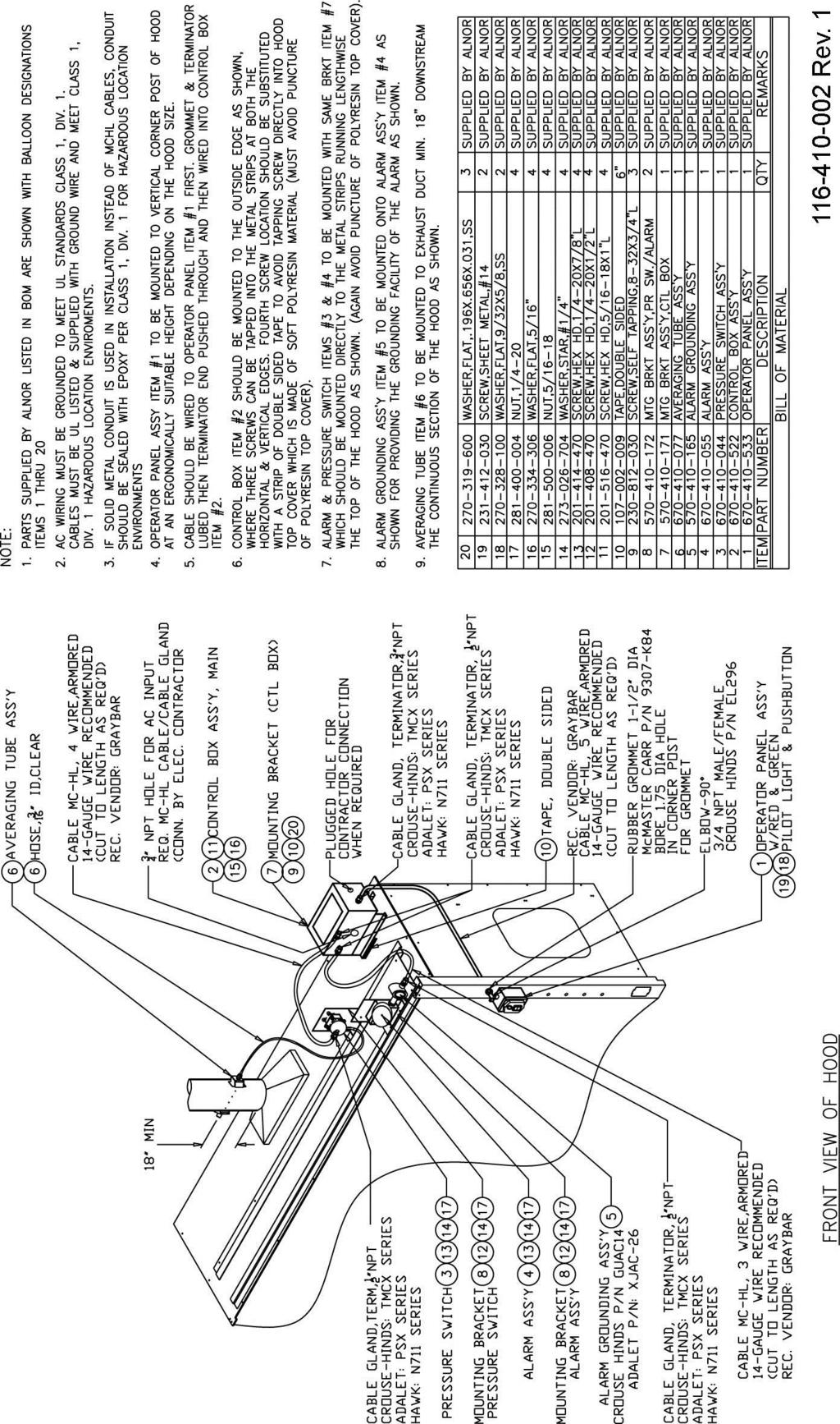
4 TABLE OF CONTENTS Section 1 Introduction... 2 General Description... 2 Component Identification... 2 Section 2 Installation... 4 Warning/Danger... 4 Installing the Pressure Averaging Tube... 4 Installing the Control Box... 5 Installing the Pressure Switch... 5 Installing the Alarm Bell... 6 Installing the Operator Panel... 6 Installing the MCHL Cable/Glands... 6 Electrical Wiring... 7 Section 3 Calibration... 8 Overview... 8 Tools Required... 8 Procedure... 8 Section 4 Normal Operation Normal Conditions Alarm Conditions System Test Section 5 Troubleshooting and Service Troubleshooting Guide Service Requests Section 6 Mounting Template Pressure Averaging Tube Appendix Drawings Installation Drawing Wiring Drawing
5 SECTION 1 Introduction General Description The AirGard 410HE Monitor is designed to continuously monitor airflow/pressurization through fume hoods that are defined as explosion-proof or are used in environments in which all equipment must be explosion-proof or intrinsically safe. The 410HE utilizes a pressure switch as the main sensing component. When pressurization drops below a user-determined level, the monitor activates both audio and visual alarm indicators to alert personnel that the airflow at the face of the hood is inadequate. An alarm relay is also activated. The monitor is supplied with a pressure averaging tube. The pressure averaging tube is designed to span the entire width of the exhaust duct. Read this manual entirely before calibrating, configuring, and using the AirGard 410HE. If you need assistance or any further explanation regarding this instrument, please contact TSI or your TSI distributor. Component Identification Control Box Alarm Relay Output Port Audio Alarm (Bell) Pressure Switch Pressure Averaging Tube AC Power Inlet Port Operator Panel Test/Reset Button Status LEDs Figure 1 Overall Schematic Diagram Pressure Averaging Tube A inch (16 mm) diameter stainless steel tube which extends through the exhaust duct. It is 16.5 inches (419 mm) long and is connected to the pressure switch via a flexible polyurethane hose. Figure 2 Pressure Averaging Tube Pressure Switch A sensitive, pressure-activated switch housed in an explosion-proof enclosure mounted on the top of the fume hood. The switch is activated when the airflow drops, the static pressure 2
6 in the duct will also drop. When the pressure goes below a user-set level, the pressure switch activates the monitor s audio and visual alarms as well as the alarm relay. Control Box This serves as a junction box which links the monitor s pressure switch, audio alarm indicator, and operator control box. This explosion-proof enclosure also houses the instrument s power and alarm relay connections. It is mounted on the top of the fume hood. Operator Panel An explosion-proof box is mounted on the side of the fume hood, the Operator Panel houses the monitor s Test/Reset button and Indicator LEDs. Test/Reset Button Silences the audible alarm. May also be used to manually activate the alarm circuits. Red (Alarm) LED Lights when a low airflow/pressurization condition is detected. Green (Normal) LED Lights when airflow/pressurization is above the pre-set alarm level. Audio Alarm An explosion-proof bell which is activated whenever a low airflow/pressurization condition is detected. 3
7 SECTION 2 Installation WARNING All connections and wiring must conform to U.S. National Electrical Code requirements for Class I, Division 1 hazardous areas. Only licensed/ experienced electricians should perform this installation. Consult local ordinances for any other hazardous location wiring requirements before starting. DANGER Always wear eye protection when using power tools. Observe all necessary precautions when installing or repairing monitors near electrical equipment. Refer to the Installation drawing (see Appendix) for the general layout of the electrical enclosures. Details of mounting each of the individual devices are given here. Installing the Pressure Averaging Tube NOTE: The Pressure Averaging Tube should be located upstream of the duct damper about one exhaust duct diameter above the hood collar, but not more than 36 inches (91.4 cm) above the collar. 1. Using the template at the rear of this manual as a guide, mark the three hole locations in one side of the fume hood exhaust duct and then mark the other three locations directly opposite (180 ) the first three. 2. Drill the two 3/4 inch (19 mm) diameter holes, located in the middle on each side, directly opposite (180 ) the first. 3. Drill the four 3/32 inch (2.4 mm) mounting holes (two on each side, one left and one right of the ¾ inch holes previously drilled), for the foam-backed mounting bracket. 4. Screw the foam-backed mounting brackets to the fume hood exhaust duct. Four #4 sheet metal screws are provided for this purpose. 5. Connect the Pressure Averaging Tube through the foam-backed mounting brackets. Make sure that the small openings along the length of the tube are pointed directly downstream and that the tube is centered in the duct. On smaller ducts, make sure that the tube protrudes equally from each side of the duct. This helps ensure that the pressure sampling holes are exposed only to the duct static pressure and not room pressure. 4
8 Side View Holes in tube face downstream (away from airflow) Top View Figure 3 Pressure Averaging Tube Positioning 6. Attach the flexible hose to the barbed hose fitting on one end of the Pressure Averaging Tube. 7. Connect the opposite end of the flexible tube to the hose fitting on the Pressure Switch enclosure. Installing the Control Box Mount the Control Box on the right rear of the fume hood as shown in the installation drawing (see Appendix). Position the box so that the ¾ NPT hole for the input power is facing the front of the fume hood. Use the available sheet metal mounting strips or any solid metallic component on the roof of the hood to attach the Control Box mounting bracket. (Some hoods may vary slightly in their construction.) Place the mounting bracket on top of the fume hood as a template to mark holes for the screws. ONLY MARK LOCATIONS ON THE SHEET METAL MOUNTING BRACKETS. Drill marked locations with a 1/8 drill. DO NOT DRILL THROUGH THE FUME HOOD WALLS OR CEILING. NOTE: Three #8 sheet metal screws provided should be placed on the two outer edges of the roof to avoid roof puncture and ultimately leakage of gases from the hood (outer edges are solid and are safe for penetrating). A strip of double-sided tape is provided for use at the fourth corner that is further inwards (also to avoid roof puncture). Attach the Control Box mounting plate with the #8 Sheet metal screws. Use the double-sided tape to secure the most inward corner of the mounting bracket. Attach the Control Box to the mounting plate with the mounting hardware supplied per installation drawing provided. Installing the Pressure Switch Mount the Pressure Switch on the second available sheet metal mounting strip on the fume hood as shown in the installation drawing, or to any solid metallic component (again avoid puncture of the roof). Use the mounting bracket as a template to mark the holes. Drill the marked locations with a 9/32 drill. Use the available sheet metal mounting strips to attach the Pressure Switch mounting bracket. Attach the Pressure Switch to the mounting bracket with mounting hardware provided per installation drawing. 5
9 IMPORTANT: NOTE PROPER ORIENTATION OF THE PRESSURE SWITCH. SWITCH SHOULD BE MOUNTED WITH PRESSURE INLET PORT POINTED DOWNWARDS IN SIX O CLOCK POSITION AS SHOWN ON THE INSTALLATION DRAWING. SWITCH FUNCTION MAY BE IMPAIRED IF INVERTED. Attach the 3/16 diameter hose between the Pressure Switch hose barb and the hose barb on the Pressure Averaging Tube. Cut to length as required. Installing the Alarm Bell Mount the Alarm Bell to the first available sheet metal mounting strip, or a solid/metallic component on the fume hood as shown in the installation drawing. Use the mounting bracket as a template to mark the holes. Drill the marked locations with a 1/8 (3mm) drill. Use the available sheet metal mounting strips to attach the Alarm Bell mounting bracket. Attach the grounding assembly to the Alarm Bell, tightening properly for hazardous locations sealing. Tighten properly until grounding box cover faces forward or upward. Attach the Alarm Bell and grounding box assembly to the mounting bracket with the mounting hardware supplied per installation drawing. IMPORTANT: NOTE PROPER ORIENTATION OF THE BELL. BELL SHOULD BE MOUNTED SUCH THAT THE AC WIRING INPUT IS POINTED TO THE RIGHT AT THREE O CLOCK POSITION AS SHOWN ON THE INSTALLATION DRAWING. BELL FUNCTION MAY BE IMPAIRED IF INVERTED. Installing the Operator Panel Attach 90 elbow (part not supplied) to Operator Panel. Tighten properly for hazardous location and align the elbow to point towards the fume hood when fully tightened. Use the Operator Panel as a template to mark two mounting holes and one clearance hole for electrical connection to the right side of the fume hood as shown on the installation drawing. Drill the two marked locations with a 13/64 (5 mm) drill for mounting and an appropriate clearance hole (1.75, 44 mm recommended for use with McMaster Carr rubber grommet 9307-K84 specified on installation drawing) for the electrical connection to the 90 elbow. If using Metal Clad Hazardous Location, MCHL cable (not supplied), cut to length, terminate using proper techniques and attach to the 90 elbow. Feed end of MCHL cable through clearance hole and attach Operator Panel to the fume hood using mounting hardware supplied per installation drawing. If using other approved hazardous location wiring, see installation drawing and configure appropriately. Installing the MCHL Cable/Glands Although the use of Metal Clad Hazardous Location Cable is widely accepted, consult local ordinances for exact requirements. NOTE: SOME ORDINANCES MAY REQUIRE SOLID METAL CONDUIT. The installation drawing is shown for a typical MCHL installation. Since the MCHL cable and cable glands are not provided, details on how to cut and terminate these cables are not provided here. Consult the cable and cable gland manufacturer for these details. 6
10 See below for general wiring instructions. Electrical Wiring Wiring components: For convenience, TSI has provided information on typical flexible hazardous location wiring components. If this is allowed in the location where the installation is being performed, the description of the components found on the installation drawing should be sufficient to get all required materials. If these are not allowed, consult a local expert in hazardous location wiring. NOTE: USE OF SOLID METAL CONDUIT MAY BE REQUIRED BY SOME LOCAL ORDINANCES. IF METAL CONDUIT IS USED, CONDUIT SHOULD BE THOROUGHLY SEALED AT TERMINATION WITH EPOXY SEAL PER CLASS I, DIV. 1 FOR HAZARDOUS LOCATION ENVIRONMENT. All electrical enclosures should be mounted before wiring. See the wiring diagram (see Appendix) for detailed wiring information. Connection tables have been provided to identify proper connections between various alarm system components. All specified flexible cables have a separate uninsulated ground conductor. Use this ground conductor to connect the ground screws (located in the four housings) together. AC Power The 120 VAC, 60 Hz power connection (hot and neutral) is made on the terminal board inside the Control Box. The ground connection is made on the grounding screw fastened to the base of the box. The AC wiring is brought into the box through the Power In port on the side of the box. See installation drawing. Optional Auxiliary Alarm Relay The alarm signal may be output to an auxiliary device such as a light or remote horn via an alarm relay located on the terminal board inside the Control Box. This relay has a nominal switching capacity of 1 amp at 30 VDC and 0.5 amp at 125 VAC. It may be wired for either normally open (N.O.) or normally closed (N.C.) operation. 7
11 Overview SECTION 3 Calibration The AirGard 410HE Airflow Monitor must be calibrated before first use and checked regularly thereafter. Fume hoods vary in design and performance. Because each hood installation and its airflow pattern is unique, this monitor must be calibrated in the field on the fume hood in which it is installed. WARNING Calibration of this instrument should only be performed by qualified personnel. Proper guidelines for monitoring any ventilation apparatus are established on the basis of toxicity or hazards of the materials used, or the operation conducted within the ventilation apparatus. Personnel calibrating the AirGard 410HE must be completely aware of the regulations and guidelines specific to its application. If you need a reference on performing traverses on fume hoods, please consult ANSI/ASHRAE Method of Testing Performance of Laboratory Fume Hoods, section 6.2 Face Velocity Measurements. Tools Required 1. Calibrated thermo-anemometer rated for hazardous environments. Suggested instruments include the Alnor Model 9880 and 9850 which have the following safety rating: UL Listed intrinsically safe for use in hazardous locations for Class I, Groups C and D, Class II, Groups E, F, and G, and Class III, when recommended batteries are used. 2. Small slotted screwdriver. Procedure 1. Double check installation to verify that the 410HE monitor, power supply, and any ancillary equipment are properly installed. 2. Allow at least 10 minutes for the pressure switch to warm up. 3. Determine the alarm set point. This is the condition where the monitor will indicate a low flow condition. The red LED on the Operator Panel will light at this point. Consult the facility s Industrial Hygiene Officer for the proper set point. NOTE: This device senses the duct static pressure. Different hoods may require different duct static pressure to generate the same face velocity. 4. Set the sash at the working height and adjust the fume hood airflow to the low alarm set point (as determined in step 3, above). One method is to close the volume damper (if available) of the ductwork. This damper must be downstream of the pressure tap / pressure averaging tube. WARNING This method is only used as a temporary means of setting the low flow set point. Make certain that airflow is restored to the proper level after calibration. 5. Using a properly calibrated thermo-anemometer, determine the velocity through the face of the hood by taking a detailed velocity traverse. Divide the face area of the hood into equal partitions. One reading per square foot of face area is recommended for an accurate traverse. Compute the average velocity for this area. 8
12 NOTE: The pressure switch response time may be as long as 10 to 25 seconds when the applied pressures are near the set point. 6. If the red LED is initially lit, slowly turn the adjustment screw on the pressure switch clockwise until the green LED lights and then slowly turn the adjustment screw counter-clockwise until the red LED again lights. If the green LED is initially lit, slowly turn the adjustment screw on the pressure switch counterclockwise until the red LED lights. IMPORTANT: To allow for the delayed reaction of the pressure switch, these adjustments must be made in small increments, at intervals up to 25 seconds each. 7. Restore normal airflow to the fume hood. NOTE: Due to the hysteresis of the pressure switch, the sash of the fume hood may need to be nearly closed to generate sufficient duct static pressure to reset the pressure switch to a good flow (green LED lit) condition. Upon restoring the airflow to the normal level, drop the sash down to reset the alarm to a non-alarm status and then return the sash to the working height. The green LED should remain lit. 8. Verify the alarm setting by establishing a low flow condition (as in step 4). If the alarm does not activate, repeat steps 5 through 8. 9
13 SECTION 4 Normal Operation Normal Conditions When proper airflow/pressurization conditions are maintained in the fume hood, the green LED on the Operator Panel will be lit. Alarm Conditions In the event that a low airflow/pressurization condition is detected, the audible alarm (bell) will sound and the red LED on the Operator Panel will light. The alarm relay will also be energized. Due to the response time of the pressure switch, there may be a delay of 10 to 25 seconds from the onset of the low airflow alarm condition to the activation of the alarm indicators. Press the Test/Reset button on the Operator Control Box to acknowledge the alarm. This will silence the bell. The red LED will remain lit and the alarm relay will remain energized until the airflow/pressurization is restored to a normal level. NOTE: Due to the hysteresis of the pressure switch, the sash of the fume hood may need to be nearly closed to generate sufficient duct static pressure to reset the pressure switch to a good flow (green LED lit) condition. Upon restoring the airflow to the normal level, drop the sash down to reset the alarm to a non-alarm status and then return the sash to the working height. The green LED should remain lit. System Test The audible alarm, alarm relay, and status LEDs can be tested by pressing and holding the Test/Reset button for at least 2 seconds when airflow/pressurization is at a normal level (green LED lit). The system will return to normal operation when the Test/Reset button is released. 10
14 SECTION 5 Troubleshooting and Service Troubleshooting Guide Problem Possible Cause / Corrective Action Neither LED lit. Alarm does not activate immediately. Power is off; restore power as required. Pressure sensor response may be delayed 10 to 25 seconds. This is normal. Alarm condition not detected. Frequent or continuous alarm conditions Static pressure in duct too high for the pressure switch. Alarm cannot be set properly. Hose connecting pressure averaging tube and pressure switch not properly attached. Check and correct as required. Pressure switch requires adjustment. Insufficient airflow. Pressure switch requires adjustment. Hood performance may be affected by other hoods or poorly placed air diffusers nearby. Contact TSI for information on higher range pressure switches. Service Requests If you need assistance, please contact TSI. 11
15 D SECTION 6 Mounting Template Pressure Averaging Tube 12
16 APPENDIX Installation and Wiring Drawings 13
17 14
18 15
19 AIRGARD 410HE MONITOR SPECIFICATIONS Operator Control Visual Indicators Audible Indicator Pressure Switch Specifications Operating Range Approximate minimum maximum setpoint Alarm Relay Output Safety Rating Operating Conditions Power Requirement Test/Reset button. Green LED airflow OK; Red LED low airflow. Minimum audible rating 88 db at 10 ft (3.05 m) 0.07 to 0.15 in H 2 O 0.04 in H 2 O 0.06 in H 2 O Nominal switching capacity 1A at 30 VDC, 0.5A at 125 VAC; form C relay. Designed to meet the requirements of the U.S. National Electrical Code (NEC) for use in Class I, Division 1, Group C and D environments. 55 to 86 F (12.8 to 30 C); 5% to 95% non-condensing RH. 120 VAC (±10%), 60 Hz., 0.25 amp maximum. 16
 874-2811 Telephone (651) 490-2811 October")

20 TSI Incorporated Alnor Products 500 Cardigan Road Shoreview, MN USA Toll Free (800) Telephone (651) October 2013 Fax (651) Printed in USA Part No Rev.5 Copyright TSI Incorporated
Static Pressure Alarm For Hazardous Location Fume Hoods
 Static Pressure Alarm For Hazardous Location Fume Hoods Models: XPA1-0715 Class 1, Division 1, Group C, D 120V/15A/60Hz Pressure range 0.07 to 0.15 in-wg XPA1-1550 Class 1, Division 1, Group C, D 120V/15A/60Hz
FUME HOOD MONITOR ALNOR AIRGARD 200
 FUME HOOD MONITOR ALNOR AIRGARD 200 OWNER S MANUAL P/N 116670080, REV 09 SEPTEMBER 2014 LIMITATION OF WARRANTY AND LIABILITY (effective April 2014) (For country-specific terms and conditions outside of
Model 405 AIRGARD Fume Hood Monitor
 INSTALLATION AND MAINTENANCE INSTRUCTIONS Model 405 AIRGARD Fume Hood Monitor A TSI Company Model 405 AIRGARD Fume Hood Monitor Specifications Instrument Dimensions Instrument Weight Shipping Weight Green
AirGard 385 Fume Hood Monitor
 OWNER S MANUAL AirGard 385 Fume Hood Monitor A TSI Company AIRGARD 385 MONITOR SPECIFICATIONS Digital Display Display Units 3 digit, 7-segment liquid crystal display. Feet per minute () or meters per second
FUME HOOD MONITOR ALNOR AIRGARD 335
 FUME HOOD MONITOR ALNOR AIRGARD 335 OWNER S MANUAL P/N 116159255, REV 10 SEPTEMBER 2014 LIMITATION OF WARRANTY AND LIABILITY (effective April 2014) (For country-specific terms and conditions outside of
CRITICAL ENVIRONMENT MONITOR ALNOR AIRGARD 350 CEM
 CRITICAL ENVIRONMENT MONITOR ALNOR AIRGARD 350 CEM OWNER S MANUAL P/N 116159359, REV 06 SEPTEMBER 2014 LIMITATION OF WARRANTY AND LIABILITY (effective April 2014) (For country-specific terms and conditions
AirGard. Air Flow Monitors
 AirGard Air Flow Monitors [AirGard Lab Hood Monitors Models 200/405 Model 335 The AirGard Models 200 & 405 are simple, go/no-go lab hood monitors designed to warn users of unsafe conditions. The flush-mount
AFA 500 FUME HOOD ALARMS
 AFA 500 FUME HOOD ALARMS Operating and Instruction Manual 19/7/03 Model AFA 500 Built-in or Remote sensor 2 Relay inputs 1 Relay output Com port Used for alarm indication and monitoring on Fume Cupboards
HVAC Controls Laboratory. Model EVERWATCH Face Velocity Monitor. Operation and Service Manual. P/N , Revision E October 2002
 HVAC Controls Laboratory Model 8610 EVERWATCH Face Velocity Monitor Operation and Service Manual P/N 1980154, Revision E October 2002 Model 8610 EVERWATCH Face Velocity Monitor Operation and Service Manual
PRESSURA ROOM PRESSURE CONTROLLER MODELS 8630-SC 8630-PC
 PRESSURA ROOM PRESSURE CONTROLLER MODELS 8630-SC 8630-PC OPERATION AND SERVICE MANUAL P/N 1980243, REVISION J DECEMBER 2013 PRESSURA ROOM PRESSURE CONTROLLER MODELS 8630-SC 8630-PC OPERATION AND SERVICE
Duct Mount. Installation Instructions
 Duct Mount Installation Instructions 00809-0600-4975 Legal Notice The Flame Detector described in this document is the property of Rosemount. No part of the hardware, software, or documentation may be
PRESSURA ROOM PRESSURE MONITOR MODEL RPM10 AND RPM20
 PRESSURA ROOM PRESSURE MONITOR MODEL RPM10 AND OPERATION AND SERVICE MANUAL P/N 6006644, REVISION J JULY 018 PRESSURA ROOM PRESSURE CONTROLLER MODEL RPM10 AND OPERATION AND SERVICE MANUAL P/N 6006644,
PRESSURA ROOM PRESSURE MONITOR MODELS 8630-SM 8630-PM
 PRESSURA ROOM PRESSURE MONITOR MODELS 8630-SM 8630-PM OPERATION AND SERVICE MANUAL P/N 1980242, REVISION G JUNE 2013 PRESSURA ROOM PRESSURE MONITOR MODELS 8630-SM 8630-PM OPERATION AND SERVICE MANUAL
PRESSURA ROOM PRESSURE MONITOR MODEL RPM10 AND RPM20
 PRESSURA ROOM PRESSURE MONITOR MODEL RPM10 AND OPERATION AND SERVICE MANUAL P/N 6006644, REVISION A JULY 01 PRESSURA ROOM PRESSURE CONTROLLER MODEL RPM10 AND OPERATION AND SERVICE MANUAL P/N 6006644,
Three Phase Simplex. Installation (937) Installation Instructions and Operation/Troubleshooting Manual. Installation of Floats.
 Installation Instructions and Operation/Troubleshooting Manual. Installation of Floats.") Three Phase Simplex Installation Instructions and Operation/Troubleshooting Manual This control panel must be installed and serviced by a licensed electrician in accordance with the National Electric Code
Three Phase Simplex Installation Instructions and Operation/Troubleshooting Manual This control panel must be installed and serviced by a licensed electrician in accordance with the National Electric Code
PRESSURA ROOM PRESSURE CONTROLLER MODEL RPC30
 PRESSURA ROOM PRESSURE CONTROLLER MODEL RPC30 OPERATION AND SERVICE MANUAL P/N 6006643, REVISION C AUGUST 2015 PRESSURA ROOM PRESSURE CONTROLLER MODEL RPC30 OPERATION AND SERVICE MANUAL P/N 6006643, REVISION
FLCH4R Garage and Utility Electric Heater
 FLCH4R Garage and Utility Electric Heater Installation, Operation & Maintenance Instructions Model No. Volts Amps Watts BTU/HR Phase High Low High Low High Low Min Fuse Size* FLCH4R 208 17.3 8.66 3600
Sentry LIQUID LEVEL GAUGE MODEL 200 or 200C OWNER MANUAL REV 1.7 SEPT08 PAGE 1 OF 12
 PAGE 1 OF 12 TABLE OF CONTENTS PAGE 1. SAFETY PRECAUTIONS 1.1. Electrical shock 3 2. APPLICATION 3 3. INSTALLATION 3.1. Mount indoor alarm display 3.2. Mount the outdoor junction box 3.3. Install interconnecting
POSITIVE AND NEGATIVE DUCT ACCREDITATION (PANDA) SYSTEM MODEL PAN231 SERIES (PANDA LIGHT)
 SYSTEM MODEL PAN231 SERIES (PANDA LIGHT)") POSITIVE AND NEGATIVE DUCT ACCREDITATION (PANDA) SYSTEM MODEL PAN231 SERIES (PANDA LIGHT) OPERATION AND SERVICE MANUAL P/N 6006886, REVISION C JULY 2017 ii Copyright TSI Incorporated / 2013 2017 / All
POSITIVE AND NEGATIVE DUCT ACCREDITATION (PANDA) SYSTEM MODEL PAN231 SERIES (PANDA LIGHT) OPERATION AND SERVICE MANUAL P/N 6006886, REVISION C JULY 2017 ii Copyright TSI Incorporated / 2013 2017 / All
MaxLite LED VAPOR TIGHT LINEAR FIXTURES
 A cost effective LED Vapor Tight Fixture features a full length polycarbonate lens and a one-piece white glass reinforced polyester (GRP) body. Designed to meet or exceed seven to 10 foot-candles at 8
Model Gas Alarm Panel APPLICABILITY & EFFECTIVITY. This manual provides instructions for the following Sierra Monitor products:
 Model 2102 Gas Alarm Panel APPLICABILITY & EFFECTIVITY This manual provides instructions for the following Sierra Monitor products: Model Description 2102-00 Alarm Panel 2 Channel 2102-01 Alarm Panel 2
Hydronic Manometers. Hydronic Manometer. Model HM670. Owner s Manual
 Hydronic Manometers Hydronic Manometer Model HM670 Owner s Manual LIMITATION OF WARRANTY AND LIABILITY Copyright TSI Incorporated / 2007-2008 / All rights reserved. Address TSI Incorporated / Alnor Products
MaxLite LED Vapor Tight Linear Fixture
 General Safety Information To reduce the risk of death, personal injury or property damage from fire, electric shock, falling parts, cuts/abrasions, and other hazards read all warnings and instructions
SC Installation, Operation & Application Guide
 SC 3006 Auto Changeover 7-Day Programmable Hardwired Programmable Electronic Thermostat 7-Day Programmable Single Stage Heat Pump/Non-Heat Pump Systems Backlit Display Single Stage Heat/Cool Systems Field
installation, operation & Maintenance manual Floor-mounted Induction units
 installation, operation & Maintenance manual Floor-mounted Induction units built on innovation induction units- fmfby/ fmlby/ fmtby Floor-mounted induction units FMFBY, FMLBY, & FMTBY are designed for
SC Installation, Operation & Application Guide
 SC 1800 Manual Changeover Non-Programmable Hardwired Non-Programmable Electronic Thermostat Controls Single Stage Heating Systems Millivolt and Hydronic (water or steam) System Compatible Compatible with
Reacti-Therm I and III Heating Modules
 INSTRUCTIONS Reacti-Therm I and III Heating Modules TS-18822 TS-18824 Number TS-18822 TS-18824 Description Reacti-Therm I Heating Module (single block) Reacti-Therm III Heating Module (triple block) 2101.1
Operating Instructions & Parts Manual. Silent Low-Profile Ceiling Fans. Models 3DPE2A, 3DPE3A, 1UBH6B, 1UBH7B, 1UBH8A, 5AE68B, 5AE69A
 Operating Instructions & Parts Manual EN Silent Low-Profile Ceiling Fans Models 3DPE2A, 3DPE3A, 1UBH6B, 1UBH7B, 1UBH8A, 5AE68B, 5AE69A 465933 PLEASE READ AND SAVE THESE INSTRUCTIONS. READ CAREFULLY BEFORE
PRESSURA ROOM PRESSURE CONTROLLER MODEL RPC30
 PRESSURA ROOM PRESSURE CONTROLLER MODEL RPC30 OPERATION AND SERVICE MANUAL P/N 6006643, REVISION G JULY 2018 PRESSURA ROOM PRESSURE CONTROLLER MODEL RPC30 OPERATION AND SERVICE MANUAL P/N 6006643, REVISION
MaxLite LED Round Pendant Highbay Series
 General Safety Information To reduce the risk of death, personal injury or property damage from fire, electric shock, falling parts, cuts/abrasions, and other hazards read all warnings and instructions
RK-03 Hydrogen Detector Operator s Manual
 61-1001RK-03 Hydrogen Detector Operator s Manual Part Number: 71-0371 Revision: P1 Released: 5/26/15 www.rkiinstruments.com WARNING Read and understand this instruction manual before operating detector.
PRESSURA ROOM PRESSURE MONITOR MODEL RPM10 AND RPM20
 PRESSURA ROOM PRESSURE MONITOR MODEL RPM10 AND OPERATION AND SERVICE MANUAL P/N 6006644, REVISION F MAY 017 PRESSURA ROOM PRESSURE CONTROLLER MODEL RPM10 AND OPERATION AND SERVICE MANUAL P/N 6006644,
Sentry LIQUID LEVEL CONTROLLER MODEL 120 OPERATING MANUAL.
 Sentry LIQUID LEVEL CONTROLLER MODEL 120 OPERATING MANUAL www.aquaticsentry.com TABLE OF CONTENTS 1. SAFETY PRECAUTIONS... 3 2. APPLICATION... 3 2.1 HIGH AND LOW LEVEL ALARM 2.2 PUMP DOWN CONTROLLER 2.3
Sentry LIQUID LEVEL ALARM MODEL 100 OPERATING MANUAL.
 Sentry LIQUID LEVEL ALARM MODEL 100 OPERATING MANUAL www.aquaticsentry.com TABLE OF CONTENTS 1. SAFETY PRECAUTIONS... 3 2. APPLICATION... 3 2.1 HIGH Liquid Level Alarm 2.2 LOW Liquid Level Alarm 3. INSTALLATION...
Ion Genesis II Pump Controller Digital Level Control with Pump Alternation and High Water Alarm
 Page 1 of 8 General Overview Thank you for purchasing an Ion Genesis controller. Take the time to read the instructions carefully before using this appliance. We strongly recommend that you keep this instruction
DBF 4XL Dryer Booster Fans
 Installation and Operation Manual Item #: 401315 Rev Date: 050814 DBF 4XL Dryer Booster Fans DBF4XL Kit Includes: Dryer Booster Fan, 1 pc Fan Mounting Bracket and Hardware, 1 pc Wall Label (Mount on wasll
MaxLite LED MICRO-T PANEL
 ` Installation Instructions General Safety Information To reduce the risk of death, personal injury or property damage from fire, electric shock, falling parts, cuts/abrasions, and other hazards read all
SUREFLOW ROOM PRESSURE CONTROLLER MODELS BAC
 SUREFLOW ROOM PRESSURE CONTROLLER MODELS 8636 8636-BAC OPERATION AND SERVICE MANUAL P/N 1980441, REVISION H FEBRUARY 2013 SUREFLOW ROOM PRESSURE CONTROLLER MODELS 8636 8636-BAC OPERATION AND SERVICE MANUAL
Combustible Gas Sample-Draw Detector Operator s Manual
 35-3001-01 Combustible Gas Sample-Draw Detector Operator s Manual Part Number: 71-0282RK Revision: A Released: 8/3/17 www.rkiinstruments.com WARNING Read and understand this instruction manual before operating
Remote Relay Module (RRM)
") Remote Relay Module (RRM) Instruction Manual WARNING THIS MANUAL MUST BE CAREFULLY READ BY ALL INDIVIDUALS WHO HAVE OR WILL HAVE THE RESPONSIBILITY FOR INSTALLING, USING OR SERVICING THIS PRODUCT. Like
Remote Relay Module (RRM) Instruction Manual WARNING THIS MANUAL MUST BE CAREFULLY READ BY ALL INDIVIDUALS WHO HAVE OR WILL HAVE THE RESPONSIBILITY FOR INSTALLING, USING OR SERVICING THIS PRODUCT. Like
Model AV1LED Audio-Visual LED Light Installation and Maintenance Manual
 Model AV1LED Audio-Visual LED Light Installation and Maintenance Manual 2561528A REV. A 810 Printed in U.S.A. Warranty Seller warrants all goods for five years on parts and 2-1/2 years on labor, under
Air Cleaning Equipment, Inc. 303 N. Main St. Broadway, NC iers.com
 Read and Save These Instructions Horizon Galaxy - Installation and Operations Manual Air Cleaning Equipment, Inc. 303 N. Main St. Broadway, NC 27505 www.horizondehumidif iers.com 1 Safety Notes: The Horizon
SYSTEM CONTROL KIT Model: CK-41P
 SYSTEM CONTROL KIT Model: CK-41P READ THE INSTALLATION INSTRUCTIONS CAREFULLY & COMPLETELY BEFORE BEGINNING THE INSTALLATION! Designed for use with the SWG Series Power Venter for controlling Natural Gas
GAS MONITOR Model Model
 Sierra Monitor Corporation 1991 Tarob Court, Milpitas, CA 95035 (408) 262-6611 (800) 727-4377 (408) 262-9042 - Fax E-mail: sierra@sierramonitor.com Web Site: www.sierramonitor.com GAS MONITOR Model 2350-00
RK / RK Methane Detector Operator s Manual
 61-1006RK / 61-0192RK Methane Detector Operator s Manual Part Number: 71-0228RK Revision: 0 Released: 10/29/18 www.rkiinstruments.com WARNING Read and understand this instruction manual before operating
RK Carbon Monoxide Transmitter Operator s Manual
 65-2335RK Carbon Monoxide Transmitter Operator s Manual Part Number: 71-0177RK Revision: 0 Released: 4/12/11 RKI Instruments, Inc. www.rkiinstruments.com WARNING Read and understand this instruction manual
RK Hydrogen Sulfide Transmitter Operator s Manual
 65-2331RK Hydrogen Sulfide Transmitter Operator s Manual Part Number: 71-0176RK Revision: B Released: 11/26/14 RKI Instruments, Inc. www.rkiinstruments.com WARNING Read and understand this instruction
installation, operation & Maintenance manual Floor-mounted Induction units acb 30/35
 installation, operation & Maintenance manual Floor-mounted Induction units acb 30/35 built on innovation acb 30 & 35 Active Chilled Beam Models ACB30 & ACB35 are designed for installation in the ceiling
INSTALLER S & OWNER S MANUAL
 INSTALLER S & OWNER S MANUAL HVAC INSTALLER: PLEASE LEAVE MANUAL FOR HOMEOWNER DEH 3000R Part No. 4028407 Dehumidifier & Ventilation System Controller 4201 Lien Road, Madison, WI 53704 TOLL-FREE (800)-533-7533
24 VAC SYSTEM CONTROL KIT Model: CK-91F and CK-91FG
 24 VAC SYSTEM CONTROL KIT Model: CK-91F and CK-91FG Designed for use with the SWG Series Power Venter for controlling Natural Gas or L.P. Gas draft induced appliances with a 24 VAC Gas Valve and a 30-millivolt
GG-EM ENTRANCE MONITOR. Installation and Operation Manual
 GG-EM ENTRANCE MONITOR Installation and Operation Manual 2 GG-EM Warning Use this product only in the manner described in this manual. If the equipment is used in a manner not specified by Calibration
RK-05 Combustible Gas Transmitter Operator s Manual
 65-2405RK-05 Combustible Gas Transmitter Operator s Manual Part Number: 71-0180RK Revision: 0 Released: 2/16/11 RKI Instruments, Inc. www.rkiinstruments.com WARNING Read and understand this instruction
LV-5 Direct Contact Low Voltage Detector and LV-5/K01 Kit including LV-PT Tester, Holster and Available Accessories
 LV-5 Direct Contact Low Voltage Detector and LV-5/K01 Kit including LV-PT Tester, Holster and Available Accessories Operating & Instruction Manual 1475 Lakeside Drive Waukegan, Illinois 60085 U.S.A. 847.473.4980
SC Installation, Operation & Application Guide
 SC 5211 2-Stage Heat Pump Auto Changeover Hardwire Programmable Electronic Thermostat 7-Day, 5-2-Day or 5-1-1-Day Programmable Configurable 2-Stage Heat Pump Systems Large Display With Backlight Selectable
INSTALLATION AND OPERATING INSTRUCTIONS FOR THE VEHICLE-MOUNTED RADIATION DETECTION SYSTEM
 INSTALLATION AND OPERATING INSTRUCTIONS FOR THE VEHICLE-MOUNTED RADIATION DETECTION SYSTEM D-tect Systems 11814 South Election Road, Suite 200 Draper, UT 84020 www.dtectsystems.com 1 Introduction The mini
RK-02 Multi Point Detector Operator s Manual
 65-2485RK-02 Multi Point Detector Operator s Manual Part Number: 71-0237RK Revision: A Released: 11/26/14 RKI Instruments, Inc. www.rkiinstruments.com WARNING Read and understand this instruction manual
Beacon 800 Gas Monitor Operator s Manual
 Beacon 800 Gas Monitor Operator s Manual Part Number: 71-0037RK Revision: F Released: 4/18/17 www.rkiinstruments.com Product Warranty RKI Instruments, Inc. warrants gas alarm equipment sold by us to be
Ion Endeavor Pump Controller Digital Level Control with Pump Alternation and High Water Alarm
 Ion Endeavor Controller Digital Level Control with Alternation Page 1 of 8 General Overview The Ion Endeavor is a pump controller that senses a water level of up to 72", has a configurable water level/pump
Single Phase Simplex SXL21=3, SXL24=3, SXH21=3, and SXH24=3
 Single Phase Simplex SXL21=3, SXL24=3, SXH21=3, and SXH24=3 Manufactured by SJE-Rhombus Installation Instructions and Operation/Troubleshooting Manual 7000 Apple Tree Avenue Bergen, New York 14416 Phone:
CD6102 / CD6102 OC / CD6102-2
 PreView Display CD6102 / CD6102 OC / CD6102-2 Operating Manual www.previewradar.com PATENTS Patented under one or more of the following U.S. Patents: 5345471, 5523760, 5457394, 5465094, 5512834, 5521600,
Users Manual. LAURUS Systems, Inc. - Ph: Fax:
 Users Manual LAURUS Systems, Inc. - Ph: 410-465-5558 - Fax: 410-465-5257 - www.laurussystems.com Introduction The rad-d is a security and inspection system that detects emissions from radioactive material.
Installation and Operations Manual
 Installation and Operations Manual H-IM-LLC February 2018 Part No. 25092501 Replaces H-IM-LLC (01/2014) Lead Lag Control System Table of Contents General Safety Information 2 Inspection 2 Warranty Statement
e Bath Fan with Light User s Guide
 e Bath Fan with Light User s Guide abfl125rok Item Stock Number(s): BFL125ROK IMPORTANT INSTRUCTIONS - OPERATING MANUAL READ AND SAVE THESE INSTRUCTIONS READ CAREFULLY BEFORE ATTEMPTING TO ASSEMBLE, INSTALL,
RK/ RK Oxygen Detector Operator s Manual
 65-2494RK/65-2497RK Oxygen Detector Operator s Manual Part Number: 71-0179RK Revision: 0 Released: 2/16/11 www.rkiinstruments.com WARNING Read and understand this instruction manual before operating detector.
1040 Gas Monitor INSTALLATION AND OPERATING INSTRUCTIONS AMC-1040 WITH INTEGRAL ELECTROCHEMICAL SENSOR
 1040 Gas Monitor INSTALLATION AND OPERATING INSTRUCTIONS AMC-1040 WITH INTEGRAL ELECTROCHEMICAL SENSOR IMPORTANT: Please read these installation and operating instructions completely and carefully before
Model A Pipe Line Strainer 3, 4, 6, 8 & 10 Inch (DN80, DN100, DN150, DN200 & DN250) 175 psi (12,1 bar) General Description.
 175 psi (12,1 bar) General Description.") Technical Services: Tel: (00) 31-9312 / Fax: (00) 91-5500 Customer Service/Sales: Tel: (1) 50-5000 / (00) 55-523 Fax: (1) 50-5010 / (00) -1295 Model A Pipe Line Strainer 3,,, & 10 Inch (DN0, DN100,, DN200
Technical Services: Tel: (00) 31-9312 / Fax: (00) 91-5500 Customer Service/Sales: Tel: (1) 50-5000 / (00) 55-523 Fax: (1) 50-5010 / (00) -1295 Model A Pipe Line Strainer 3,,, & 10 Inch (DN0, DN100,, DN200
TECHNICAL ASSISTANCE TOLL FREE TELEPHONE NUMBER TECHNICAL ASSISTANCE FAX:
 ACORN SAFETY P.O. BOX 3527 CITY OF INDUSTRY, CA 91744-0527 UNITED STATES OF AMERICA WWW.ACORNSAFETY.COM INSTALLATION, OPERATION AND MAINTENANCE INSTRUCTIONS ELECTRIC ALARM WITH LIGHT AND HORN Models S0000-AL1
Carbon Dioxide Sample-Draw Detector Operator s Manual
 35-3001-05-03 Carbon Dioxide Sample-Draw Detector Operator s Manual Part Number: 71-0413 Revision: 0 Released: 8/4/17 www.rkiinstruments.com WARNING Read and understand this instruction manual before operating
RK/ RK Oxygen Detector Operator s Manual
 65-2502RK/65-2510RK Oxygen Detector Operator s Manual Part Number: 71-0074RK Revision: A Released: 3/1/11 www.rkiinstruments.com WARNING Read and understand this instruction manual before operating detector.
Insulated Ventilators. Operating Instructions & Parts Manual
 Operating Instructions & Parts Manual EN Insulated Ventilators Models 3DPE4B, 3DPE5B, 3DPE6A, 5AE70B, 5AE71B, 5AE72A, 5AE73 thru 5AE81, 6WZN1, 6WZN2, 36WG64 and 36WG65 465932 PLEASE READ AND SAVE THESE
SC Installation, Operation & Application Guide
 SC 3801 2 Heat/2 Cool 7-Day Programmable Hardwired Programmable Electronic Thermostat Programmable and Configurable Single/Dual Stage Heat Pump Systems Single/Dual Stage Heat/Cool Systems Backlit Display
Design Criteria. Installation
 Model G5 Sprinkler Guards for Use with Series DS-1 Sprinklers Standard, Deep, and No Escutcheons General Description The TYCO Model G5 Sprinkler Guards are designed for use with Series DS-1 Sprinklers
e Bath Fan with Light User s Guide
 e Bath Fan with Light User s Guide abfl100rnl, BFL125RNL Item Stock Number(s): BFL100RNL, BFL125RNL IMPORTANT INSTRUCTIONS - OPERATING MANUAL READ AND SAVE THESE INSTRUCTIONS READ CAREFULLY BEFORE ATTEMPTING
SUREFLOW ADAPTIVE OFFSET CONTROLLER MODELS BAC
 SUREFLOW ADAPTIVE OFFSET CONTROLLER MODELS 8681 8681-BAC OPERATION AND SERVICE MANUAL P/N 1980476, REVISION E FEBRUARY 2013 SUREFLOW ADAPTIVE OFFSET CONTROLLER MODELS 8681 8681-BAC OPERATION AND SERVICE
RK-05 Carbon Monoxide Detector Operator s Manual
 65-2433RK-05 Carbon Monoxide Detector Operator s Manual Part Number: 71-0189RK Revision: 0 Released: 5/17/11 RKI Instruments, Inc. www.rkiinstruments.com WARNING Read and understand this instruction manual
Model 9001EXP Alarm. NOTE TO INSTALLER: Please leave this information with the Maintenance Department. LIMITED WARRANTY
 INSTALLATION, OPERATION & MAINTENANCE INSTRUCTIONS 1455 Kleppe Lane Sparks, NV 89431-6467 (775) 359-4712 Fax (775) 359-7424 E-mail: haws@hawsco.com website: www.hawsco.com Model 9001EXP Alarm No. 2080203(24)
6502B RF Distribution
 6502B RF Distribution User Guide Revision A - March 2004 Part Number 15247-201 Table of Contents Table of Contents About this User Guide Purpose...................................................... 1
Controllers. Instruction Manual WARNING
 Controllers Instruction Manual WARNING THIS MANUAL MUST BE CAREFULLY READ BY ALL INDIVIDUALS WHO HAVE OR WILL HAVE THE RESPONSIBILITY FOR INSTALLING, USING OR SERVICING THIS PRODUCT. Like any piece of
RK Combustible Gas Transmitter Operator s Manual
 65-2400RK Combustible Gas Transmitter Operator s Manual Part Number: 71-0060RK Revision: C Released: 1/31/13 www.rkiinstruments.com WARNING Read and understand this instruction manual before operating
Models: SV1 (110V) SV1EU ( V) User s Manual. Register your product and get support at. v
 SV1EU ( V) User s Manual. Register your product and get support at. v") User s Manual Register your product and get support at www.vacmasterfresh.com Models: SV1 (110V) SV1EU (220-240V) v.2015-04.09 SAFEGUARDS Important Safeguards For your safety, always follow these basic
User s Manual Register your product and get support at www.vacmasterfresh.com Models: SV1 (110V) SV1EU (220-240V) v.2015-04.09 SAFEGUARDS Important Safeguards For your safety, always follow these basic
Laing Thermotech. Autocirc The Instant Hot Water Pump Models E1-BCANCT1W-06 and E1-BCANRT1W. Installation & Operating Manual
 Installation & Operating Manual Please read this manual carefully before attempting to install, operate or maintain the product described. Failure to comply with the information provided in this manual
Model # Airflow Monitor Warranty. Installation, Operation, Maintenance Manual. Analog Airfl ow Monitor Model Number #51403
 Model # 51403 Airflow Monitor Warranty 1 Year Limited Warranty (Effective 05.1.2014) Installation, Operation, Maintenance Manual Analog Airfl ow Monitor Model Number #51403 HEMCO warrants UniFlow Laboratory
INSTALLER S & OWNER S MANUAL
 INSTALLER S & OWNER S MANUAL HVAC INSTALLER: PLEASE LEAVE MANUAL FOR HOMEOWNER Part No. 4028539 Dehumidifier & Ventilation System Controller 4201 Lien Rd Madison, WI 53704 TOLL-FREE 1-800-533-7533 www.thermastor.com
GG-NH3-2% AMMONIA GAS SENSOR. Installation and Operation Manual
 GG-NH3-2% AMMONIA GAS SENSOR Installation and Operation Manual 2 GG-NH3-2% Warning Use this product only in the manner described in this manual. If the equipment is used in a manner not specified by Calibration
MN908 No. 282C Replaces 282B LB7013
 No. 282C Replaces 282B LB7013 Instruction Manual For Baldor Dust Control Units Models DC7, DC7 3, DC8, DC8 3, DC10, DC10 3, DC12, DC12 3 and DC14 3. For use on Grinders mounted to GA16 and GA20 pedestals
D2E Duct Smoke Detector
 INSTALLATION AND MAINTENANCE INSTRUCTIONS D2E Duct Smoke Detector Specifications Operating Temperature: 20 to 60 C Storage Temperature: 20 to 60 C Humidity: 0% to 93% Relative Humidity Non-condensing Air
Instruction Manual WARNING
 Controllers Instruction Manual WARNING THIS MANAUL MUST BE CAREFULLY READ BY ALL INDIVIDUALS WHO HAVE OR WILL HAVE THE RESPONSIBILITY FOR INSTALLING, USING OR SERVICING THIS PRODUCT. Like any piece of
EVERWATCH FACE VELOCITY MONITOR MODEL 8610
 EVERWATCH FACE VELOCITY MONITOR MODEL 8610 OPERATION AND SERVICE MANUAL P/N 1980154, REVISION H FEBRUARY 2013 EVERWATCH FACE VELOCITY MONITOR MODEL 8610 OPERATION AND SERVICE MANUAL P/N 1980154, REVISION
WATLOW IND. WATROD Modular Duct Heater Installation & Maintenance Manual I&M NUMBER: Page: 1 Date:6/11/2008 Rev: 2
 I&M NUMBER: 316-42-15-1 Page: 1 _ Pre Installation Check to make sure that heater received is the same as that ordered. Elements may come in contact with each other during shipment. Minor adjustments to
e Heater/Exhaust Fan/Light User s Guide
 e Heater/Exhaust Fan/Light User s Guide abflh70l, BFLH85L Item Stock Number(s): BFLH70L, BFLH85L IMPORTANT INSTRUCTIONS - OPERATING MANUAL READ AND SAVE THESE INSTRUCTIONS READ CAREFULLY BEFORE ATTEMPTING
Figure 1. Figure 2. See notes 1 and 2 below.
 273 Branchport Avenue Long Branch, N.J. 07740 (800) 631-2148 Thank you for using our products. www.wheelockinc. com INSTALLATION INSTRUCTIONS HORN SPEAKER WITH AMPLIFIER Use this product according to this
GASGUARD LEL 3 OPERATING & INSTALLATION MANUAL
 GASGUARD LEL 3 Ammonia Sensor OPERATING & INSTALLATION MANUAL GasGuard LEL 3 Operating and Installation Manual 2 Table of Contents 3GasGuard LEL Operating and Instruction Manual General description. 4
G Series SAVE THESE INSTRUCTIONS. (Model B) Convector Heater for Hazardous Locations GENERAL! INSTALLATION
 Convector Heater for Hazardous Locations GENERAL! INSTALLATION") G Series (Model B) Convector Heater for Hazardous Locations Type G-Series Convection Heaters are designed for use in Class I, Div. I hazardous environments. Units without control options are suitable for
G Series (Model B) Convector Heater for Hazardous Locations Type G-Series Convection Heaters are designed for use in Class I, Div. I hazardous environments. Units without control options are suitable for
Incutrol/2 Regulator
 12216-08 Model 2597A Incutrol/2 Regulator Hach Company, 1986-1996. All rights. reserved. Printed in the U.S.A. 05/95 13ed 09/96 rev2 2 Table of Contents Specifications...1 General Description...2 Setup...2
RK/ RK Combustible Gas Detector Operator s Manual
 61-1003RK/61-0190RK Combustible Gas Detector Operator s Manual Part Number: 71-0120RK Revision: 0 Released: 2/11/11 www.rkiinstruments.com WARNING Read and understand this instruction manual before operating
ion Genesis Pump Controller
 High Water Alarm Document No.: IONG_OM Page 1 of 7 Table of Contents Safety Precautions.......................... 1 General Overview.......................... 1 Installation.................................2
DEDPV-705, DEDPV-705 Hi Alt Dryer Exhaust Duct Power Ventilator (DEDPV)
") Installation and Operation Manual Item #: 483443 Rev Date: 2018-04-23 DEDPV-705, DEDPV-705 Hi Alt Dryer Exhaust Duct Power Ventilator (DEDPV) DEDPV-705 Kit Includes: Inline Fan with Integral Control, 1
Installation and Operation Manual Item #: 483443 Rev Date: 2018-04-23 DEDPV-705, DEDPV-705 Hi Alt Dryer Exhaust Duct Power Ventilator (DEDPV) DEDPV-705 Kit Includes: Inline Fan with Integral Control, 1
Please read and follow all instructions for usage and maintenance before operating the VACMASTER SV1 Immersion Circulator.
 User s Guide SV1 Thank you for purchasing the VACMASTER SV1 Immersion Circulator. The SV1 is one of the most efficient and reliable instruments for sous vide cooking. This machine, with its space-saving,
SC Installation, Operation & Application Guide
 SC 3201 Heat Pump 7-Day Programmable Hardwired Programmable Electronic Thermostat 7-Day Programmable 2-Stage Heat Pump Backlit Display Manual Changeover Simpleset Programming Title 24 Compliant / No Batteries
READ AND SAVE THESE INSTRUCTIONS WARNING! TO REDUCE THE RISK OF FIRE, ELECTRICAL SHOCK, OR INJURY TO PERSONS OBSERVE THE FOLLOWING:
 DANVER INSTALLATION INSTRUCTIONS & USE & CARE GUIDE DANVER DOHC Series Range Hood 1300 CFM DOHC Séries Models: 36 48 60 CONTENTS: Part 1 - Planning The Installation Part 2 - Electrical Connection Part