WebAlert WA500 Series Process Monitor Instruction Manual
|
|
|
- Aldous Payne
- 5 years ago
- Views:
Transcription
1 W A L C H E M IWAKI America Inc. WebAlert WA500 Process Monitor WebAlert WA500 Series Process Monitor Instruction Manual Five Boynton Road Hopping Brook Park Holliston, MA USA TEL: FAX: WEB:
2 Notice 2014 WALCHEM, Iwaki America Inc. (hereinafter Walchem ) 5 Boynton Road, Holliston, MA USA (508) All Rights Reserved Printed in USA Proprietary Material The information and descriptions contained herein are the property of WALCHEM. Such information and descriptions may not be copied or reproduced by any means, or disseminated or distributed without the express prior written permission of WALCHEM, 5 Boynton Road, Holliston, MA This document is for information purposes only and is subject to change without notice. Statement of Limited Warranty WALCHEM warrants equipment of its manufacture, and bearing its identification to be free from defects in workmanship and material for a period of 24 months for electronics and 12 months for mechanical parts and electrodes from date of delivery from the factory or authorized distributor under normal use and service and otherwise when such equipment is used in accordance with instructions furnished by WALCHEM and for the purposes disclosed in writing at the time of purchase, if any. WALCHEM's liability under this warranty shall be limited to replacement or repair, F.O.B. Holliston, MA U.S.A. of any defective equipment or part which, having been returned to WALCHEM, transportation charges prepaid, has been inspected and determined by WALCHEM to be defective. Replaceable elastomeric parts and glass components are expendable and are not covered by any warranty. THIS WARRANTY IS IN LIEU OF ANY OTHER WARRANTY, EITHER EXPRESS OR IMPLIED, AS TO DESCRIPTION, QUALITY, MERCHANTABILITY, FITNESS FOR ANY PARTICULAR PURPOSE OR USE, OR ANY OTHER MATTER Rev L July 2014
3 TABLE OF CONTENTS 1.0 INTRODUCTION SPECIFICATIONS MEASUREMENT PERFORMANCE ELECTRICAL MECHANICAL VARIABLES AND THEIR LIMITS UNPACKING & INSTALLATION UNPACKING THE UNIT MOUNTING THE ELECTRONIC ENCLOSURE INSTALLATION ICON DEFINITIONS ELECTRICAL INSTALLATION FUNCTION OVERVIEW FRONT PANEL INITIAL STARTUP COMMUNICATING WITH THE WEBALERT STARTUP SHUT DOWN OPERATION MENU SELECTION LINKS STARTUP SYSTEM SUMMARY MENU MA INPUTS MA CALIBRATION DIGITAL INPUTS ALARM SYSTEM STATUS AUTO-REPORTING DATALOG AUTO REPORT MANUAL DATALOG GRAPHING/TRENDING COMMUNICATIONS MENU ADVANCED COMMUNICATIONS SETTINGS SOFTWARE UPGRADE CONFIGURATION FILE NOTEPAD ACCESS CODES WALCHEM WEB PAGE SUB-NETWORK MAINTENANCE REPLACING THE BATTERY TROUBLESHOOTING ERROR MESSAGES SERVICE POLICY... 47
4 1.0 INTRODUCTION WebAlert is the first stand- alone remote monitoring device that can web enable your installed equipment without having to replace or upgrade it. Your key system parameters (analog and digital input signals) can now be monitored from any computer anywhere in the world - with a standard web browser. With proprietary on-demand connectivity, the WebAlert is only online when you need it, making it the world s first practical and secure industrial monitoring Internet solution. WebAlert pulls your older equipment into the Internet age with online monitoring, data logging, auto reporting and auto alarming. User defined alarms can be received by or cell phone text message. The solid state alarm relay notifies on-site personnel. Data logs can be delivered by as a spreadsheet attachment. You decide where and when you need the information and WebAlert makes it happen. Since WebAlert supports simultaneous multi-user access and Ethernet, all of its remote monitoring features are also available on local area networks (LAN). For larger installations, which require more than six analog and two digital inputs, WebAlerts can be networked together with Ethernet. In addition, settings and data may be manipulated using a computer connected directly via USB, or modem to modem without requiring an Internet connection. 1
5 2.0 SPECIFICATIONS 2.1 Measurement Performance 4-20 ma Inputs Range ma Resolution 0.03 ma Calibration ± 1 ma 2.2 Electrical Inputs Input power / VAC ±10%, 1A, 50/60 Hz Fuse 1.0A, 5 x 20mm Input signals State-Type Digital Inputs Low Speed Counter-Type Digital Inputs High Speed Counter-Type Digital Inputs Analog Inputs (1-6) Electrical: Non-Isolated 5 VDC with 301 K ohm pull-up Typical response time: < 10 seconds Devices supported: Any isolated dry contact (i.e. relay, reed switch) Support on inputs: 1 through 6 Types: Generic input Electrical: Non-Isolated 5 VDC with 301 K ohm pull-up, 0-10 Hz, 50 msec minimum width Devices supported: Any device with isolated open drain, open collector, transistor or reed switch Support on inputs: 1 through 4 Types: Contacting flowmeter, Generic counter Electrical: Non-Isolated 5 VDC with 301 K ohm pull-up, Hz, 1.25 msec minimum width Devices supported: Any device with isolated open drain, open collector, transistor or reed switch Support on inputs: 1 through 4 Types: Paddlewheel flowmeter, Generic counter 4-20 ma, 2-wire or 3 -wire, internally powered by 24 VDC, 110 ohm input resistance, 1000 ohm maximum load, Typical response time < 10 seconds Outputs Solid State Relay: Digital: Dry Contact, 0 to 40 VDC, NO AC VOLTAGE, 150 ma maximum load USB Ethernet, 10 Base T Agency Approvals Safety UL :2012 3rd Ed. CSA C22.2 No :2012 3rd Ed. IEC :2010 3rd Ed. EN :2010 3rd Ed. EMC IEC :2005 EN :2006 Note: For EN , EN the controller met performance criteria B. *Class A equipment: Equipment suitable for use in establishments other than domestic, and those directly connected to a low voltage ( VAC) power supply network which supplies buildings used for domestic purposes. 2
6 2.3 Mechanical Enclosure Material: Polycarbonate NEMA Rating: NEMA 4X (IP 66) Dimensions: 32.4 cm x 24.4 cm x 8.3 cm (12.75 x 9.60 x 3.25 ) Operating Ambient Temp: 0 to 60 C (32 to140 F) Storage Temp: -29 to 80 C (-20 to 176 F) Weight 2.0 kg. (4.5 lbs) 2.4 Variables and their Limits All menus shown may not be available. The menus that appear on your process monitor will vary with options installed and programmed. Generic 4-20 ma Input Menu 4 ma = -999,999,999 to 999,999,999 (units of measure defined by user) 20 ma = -999,999,999 to 999,999,999 (units of measure defined by user) Low Alarm Limit -999,999,999 to 999,999,999 (units of measure defined by user) High Alarm Limit -999,999,999 to 999,999,999 (units of measure defined by user) Low-Low Alarm Limit -999,999,999 to 999,999,999 (units of measure defined by user) High-High Alarm Limit -999,999,999 to 999,999,999 (units of measure defined by user) Level (4-20 ma) Input Menu ma when Tank Empty ma when Tank Full Full Tank Volume Low Alarm Limit High Alarm Limit Low-Low Alarm Limit High-High Alarm Limit 0 to 20 ma 0 to 20 ma 0 to 999,999,999 (units defined by user) -999,999,999 to 999,999,999 (units of measure defined by user) -999,999,999 to 999,999,999 (units of measure defined by user) -999,999,999 to 999,999,999 (units of measure defined by user) -999,999,999 to 999,999,999 (units of measure defined by user) Flow Meter 4-20 ma Input Menu 4 ma = 0 to 999,999,999 (units of flow rate defined by user) 20 ma = 0 to 999,999,999 (units of flow rate defined by user) Low Alarm Limit 0 to 999,999,999 (units of flow rate defined by user) High Alarm Limit 0 to 999,999,999 (units of flow rate defined by user) Low-Low Alarm Limit -999,999,999 to 999,999,999 (units of measure defined by user) High-High Alarm Limit -999,999,999 to 999,999,999 (units of measure defined by user) Total Limit 0 to 999,999,999 (units of total volume defined by user) Digital Input Menu Paddlewheel Flowmeter Input Menu K Factor (paddlewheel style) to 20,000 (Pulses per Gallon or Liter) Total Alarm Limit 0 = no limit, otherwise >0 Rate High Alarm >0 Rate Low Alarm >0 Rate High-High Alarm >0 Rate Low-Low Alarm >0 3
7 Contact Flowmeter Input Menu Volume per Contact (contact style) 0 to 1000 (units of measure defined by user) Total Alarm Limit 0 = no limit, otherwise >0 Counter Input Menu One Count = >0 Total Alarm Limit 0 =no limit, otherwise >0 Rate High Alarm >0 Rate Low Alarm >0 Rate High-High Alarm >0 Rate Low-Low Alarm >0 Alarm Output Menu Remote Alarm Delay Time Output Time Limit Alarm Hand Time Limit Auto Reporting Menu Logging Frequency Access Code Menu Session Timeout 1 to 1440 minutes 0 to 1440 minutes (0 = no limit) 1 to 1440 minutes 10 to 1440 minutes 0 to 60 minutes (0 = infinity) 3.0 UNPACKING & INSTALLATION 3.1 Unpacking the Unit Inspect the contents of the carton. Please notify the carrier immediately if there are any signs of damage to the process monitor or its parts. Contact your distributor if any of the parts are missing. The carton should contain a WebAlert series process monitor and instruction manual. Any options or accessories will be incorporated as ordered. 3.2 Mounting the Electronic Enclosure The WebAlert series process monitor is supplied with mounting holes on the enclosure. It should be wall mounted with the display at eye level on a vibration-free surface, utilizing all mounting holes for maximum stability. The enclosure is IP66 (NEMA 4X) rated, suitable for outdoor installation. The maximum ambient operating temperature is 60 degrees C (140 degrees F); this should be considered if installation is in a high temperature location. The installation site should be in close proximity to grounded AC power, the devices to be connected, and phone line or Ethernet hub (if applicable). Avoid locations that are in close proximity to sources of electrical noise (motor starters, power transformers, variable speed motor drives, radio transmitters, etc.), corrosive fumes or excessive moisture. 4
8 The enclosure requires the following clearances: Top: 5 cm (2 ) Left: 10 cm (4 ) Right: 10 cm (4 ) Bottom: 10 cm (4 ) 3.3 Installation The WebAlert receives digital and analog input signals, and sends a digital output signal. The maximum distances for these cables, using 24 AWG shielded twisted pair cable, is 1200 meters (4000 feet) for the 4-20 ma input signals and 300 meters (1000 feet) for the digital input and output signals. It is highly recommended that these cables be routed separately from any AC voltage wires, and that the cable shield drain wire is connected to earth ground at the process monitor end only. Note: Using the WebAlert process monitor in any manner other than that specified in this manual could compromise the safety of persons or property. 3.4 Icon Definitions Symbol Publication Description IEC 417, No.5019 IEC 417, No IEC 417, No Protective Conductor Terminal On (Supply) Off (Supply) ISO 3864, No. B.3.6 Caution, risk of electric shock ISO 3864, No. B.3.1 Caution 3.5 Electrical Installation The WebAlert series process monitors require the following voltages: / VAC ± 10%, 50/60 Hz, 1.0 amperes maximum. Your unit is supplied ready to be hardwired. In addition, you will be required to hardwire some or all of the input/output devices. Please refer to Figures 2 through 5 for wiring diagrams. Note: Proper grounding of this product is required. Any attempt to bypass the grounding will compromise the safety of persons and property. CAUTION! There are live circuits beneath the power supply cover! The process monitor must not be operated without this cover properly installed! CAUTION! The electrical installation of the process monitor must be done by trained personnel only and conform to all applicable National and Local codes! 5
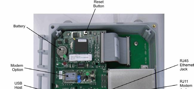
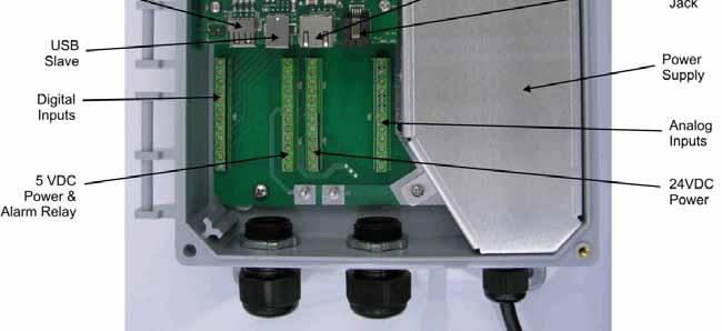
9 Figure 1 Identification of Parts 6

10 Figure 2 Wiring Diagram for AC Power Input 7

11 Figure 3 - Wiring Diagram for Digital Inputs and Outputs 8

12 DEVICES POWERED BY THE WEBALERT Figure 4 - Wiring Diagram for Analog Inputs 9

13 Figure 5 Wiring Diagram for USB Devices and Communications 10

14 4.0 FUNCTION OVERVIEW 4.1 Front Panel Status LED Alarm LED 11
15 4.2 Initial Startup Turn the power on. Be patient, the start up sequence will take about the same time as it takes a computer to boot up, approximately 2 minutes. The Status LED will flash, and when boot up is complete the WebAlert will beep 3 times. Under normal conditions, the Status LED will flash on and off every second. The WebAlert Series process monitors have a wide range of capabilities, so the steps required preparing the site for installation would be different depending upon the capability you will be using. If you want to program the WebAlert using a laptop computer to connect to the serial port on the front panel of the unit, go to the section below called Direct Connection to the USB Port. If you have a unit that is equipped with a modem, then you can take full advantage of the WebAlert. The unit is like a web server. Once you set up an Internet Service Provider (ISP) account for the unit, you can surf to it from any web connected computer to access data or reconfigure the settings. The unit can also contact you, by or cell phone text message, in case of trouble. In this case, a dedicated analog phone line that does not go through a company switchboard for the process monitor must be provided. For details, go to the section below called Remote Modem Access: Shoulder Tap. The ISP information must be entered into the WebAlert via direct connection to the USB port, via Ethernet or via the Direct Modem method before attempting a Shoulder Tap connection. If you have not yet set up an ISP account and wish to program the WebAlert from a remote location, or if you just prefer the old fashioned method of direct modem-to-modem communication, go to the section below called Direct Modem Access: Direct Tap. If you can use the Ethernet connection installed, then the WebAlert becomes like another device on a network. You can use your web browser software, enter the unit s address (assigned by your network administrator) and access data or reconfigure the unit. You will need to have a network node nearby (within 100 meters/330 feet) to connect your WebAlert process monitor. See the section below called Ethernet Connection to LAN. You may also use the Ethernet card in your laptop to communicate with the Ethernet connection in the WebAlert. This requires a special null cable and the laptop network settings must be configured to work with the WebAlert. Refer to the section below called Direct Ethernet (for a WebAlert not connected to the LAN). Uploading Configuration Files You can save all of the set points from a previously programmed unit, and then import the same set points into another unit. If you have already exported a configuration file from a previously programmed unit, you can import that file to this unit in order to make all the set points the same. If you want to save the set points of this unit for use in future units, or want to program this unit using a stored configuration file, refer to section 5.14 for specific instructions. See the appropriate section above, depending upon how you plan on exporting the configuration file; via a laptop connected to the front panel, via modem, or via Ethernet connection. 12
16 4.3 Communicating with the WebAlert Direct Connection to the USB Port Web Browser (Client) USB Hard coded Fixed IP Address: A direct USB connection to the WebAlert can be made in two ways. A temporary connection or a permanent connection can be made between a PC and the USB connector inside the unit. The cable length is limited to 5 meters (15 feet). Equipment Required An A to B USB cable. An Internet-ready computer with the following capabilities: 100 MHz minimum processor speed, 40 MB minimum RAM, Windows 2000 or newer operating system, and Windows Internet Explorer version 5.0 or higher web browser software. Features Required in the WebAlert Any WebAlert process monitor is capable of an USB connection. Utilities you need to set up on your computer An USB driver must be installed on your computer. Refer to the separate detailed instructions for this procedure. A Local Area Connection must be configured in order to establish a communication between the process monitor and your PC. See below for this procedure. Parameters that need to programmed into the WebAlert The WebAlert is capable of this type of communication without any programming by the user prior to attempting the communication. Steps Required to Establish a Connection Connect the USB cable between the WebAlert and your computer. A New Hardware Found wizard will launch. Install the driver on your PC by inserting the disc supplied and following the instructions. This needs to done only once for each PC that will be used to communicate with a WebAlert process monitor. Go to Control Panel, Network Connections, and locate the new Local Area Connection 2 that has been created. Click on the Properties button. Highlight Internet Protocol (TCP/IP) then click Properties. Click Use the following IP address and enter Click OK to exit. Open Internet Explorer and type in the address The sign-on screen of the WebAlert will come up. Type the User Name and Password (Access Code) in the text boxes and click the Submit button. The default user name is "webalert" and the default passwords are "2001" for full access, "2002" for calibration only, and "2003" for read only. These defaults can and should be changed in the Access Code page. 13

17 4.3.2 Remote Modem Access: Shoulder Tap ISP Phone line Embedded Web Server ShoulderTap Connection Utility Equipment Required An Internet-ready computer with the following capabilities: 100 MHz minimum processor speed, 40 MB minimum RAM, Windows operating system, and Windows Internet Explorer version 5.0 or higher web browser software. An active analog phone line, direct to the process monitor (without a PBX system in between) must be connected to the modem of the WebAlert. A dialup account must be established for the WebAlert with an Internet Service Provider (ISP). The connection will only be as reliable as the ISP. You should avoid small mom-and-pop ISPs unless you know that they can provide reliable connection to the Internet. Contact Walchem for recommendations. Features Required in the WebAlert The WebAlert must have the modem option installed in order to communicate via Shoulder Tap. Utilities you need to set up on your computer There are no special drivers, adapters or other software components required on the PC. Parameters that need to be programmed into the WebAlert Prior to attempting a Shoulder Tap connection, the following information needs to be entered into the Communications page of the WebAlert, either via a direct serial connection or direct modem connection (Direct Tap). Some of this information needs to be provided to you by the Internet Service Provider (ISP) that the WebAlert will use to access the Internet. The unit s phone number. The local access phone number for the ISP. More than one access number may be entered. The ISP Username that the unit will use to connect to the ISP. The ISP Password that the unit will use to connect to the ISP. Steps Required to Establish a Connection Connect your PC to the Internet. Enter the address Enter the Connection Utility Username and Password and click the Submit button. Enter the phone number of the unit and click the Connect button. After a few minutes, the sign-on screen for the WebAlert will come up. The sign-on screen of the WebAlert will come up. Type the User Name and Password (Access Code) in the text boxes and click the Submit button. The default user name is "webalert" and the default passwords are "2001" for full access, "2002" for calibration only, and "2003" for read only. These defaults can and should be changed in the Access Code page. 14
18 4.3.3 Ethernet Connection to LAN OR Unsafe Port Ethernet LAN Safe Port ROUTER Web Browser Web Browser Equipment Required An Internet-ready computer with the following capabilities: 100 MHz minimum processor speed, 40 MB minimum RAM, Windows operating system, and Windows Internet Explorer version 5.0 or higher web browser software. A connection between the PC and the local area network (LAN). An Ethernet connection between the WebAlert and the LAN. Features Required in the WebAlert All WebAlert process monitors are capable of Ethernet communications. Utilities you need to set up on your computer There are no special drivers, adapters or other software components required on the PC. Parameters that need to be programmed into the WebAlert Prior to attempting an Ethernet connection, the following information needs to be entered into the Communication page of the WebAlert, either via a direct serial connection or via the Direct Modem option. This information must be provided by the IT Administrator of the LAN. The Ethernet IP address of the WebAlert. If the unit will only be accessed by computers on the LAN then this may be a fake IP address. If the unit needs to be accessible by computers not on the LAN then this must be a real IP address. The Subnet Mask. The Gateway IP address. Steps Required to Establish a Connection Open Internet Explorer. Type in the Ethernet IP address that has been assigned by the IT Administrator. The sign-on screen of the WebAlert will come up. Type the User Name and Password (Access Code) in the text boxes and click the Submit button. The default user name is "webalert" and the default passwords are "2001" for full access, "2002" for calibration only, and "2003" for read only. These defaults can and should be changed in the Access Code page. 15

19 4.3.4 Direct Modem Access: Direct Tap Web Browser (Client) Embedded Web Server modem TELCO modem Hard coded Fixed IP Address: Equipment Required An Internet-ready computer with the following capabilities: 100 MHz minimum processor speed, 40 MB minimum RAM, Windows operating system, modem and Windows Internet Explorer version 5.0 or higher web browser software. An active analog phone line, direct to the process monitor (without a PBX system in between) must be connected to the modem of the WebAlert. Features Required in the WebAlert The WebAlert must have the modem option installed in order to communicate via Direct Tap. Utilities you need to set up on your computer A Windows dialup networking adapter must be created. This dialup networking adapter is similar to but not identical to the one used in a direct serial connection. Refer to the separate detailed instructions for this procedure. Parameters that need to be programmed into the WebAlert The WebAlert is capable of this type of communication without any programming by the user prior to attempting the communication. Steps Required to Establish a Connection Create the dialup networking adapter on your PC. This needs to done only once for each PC that will be used to communicate with a WebAlert process monitor. Use the dialup networking adapter to connect the PC to the WebAlert. Open Internet Explorer. Type in the address The sign-on screen for the WebAlert will come up. The sign-on screen of the WebAlert will come up. Type the User Name and Password (Access Code) in the text boxes and click the Submit button. The default user name is "webalert" and the default passwords are "2001" for full access, "2002" for calibration only, and "2003" for read only. These defaults can and should be changed in the Access Code page. 16
20 4.3.5 Direct Ethernet (for a WebAlert not connected to a LAN) Web Browser (Client) Fixed IP Address User Assigned Ethernet Cross-Over Cable User Assigned Fixed IP Address Gateway + Subnet Mask Equipment Required An Internet-ready computer with the following capabilities: 100 MHz minimum processor speed, 40 MB minimum RAM, Ethernet card, Windows operating system, and Windows Internet Explorer version 5.0 or higher web browser software. A null Ethernet cable connection between the PC and WebAlert. Features Required in the WebAlert All WebAlert process monitors are capable of Ethernet communications. Utilities you need to set up on your computer There are no special drivers, adapters or other software components required on the PC. However if your laptop is used on a LAN it is likely that you will have to change your network TCP/IP properties to use a specific IP address for your PC instead of obtain an IP address automatically. You will have to specify the IP address, as well as the Subnet Mask and Gateway IP address. To set the PC to work with default WebAlert settings, the IP address is , subnet mask is , and the gateway is Parameters that need to be programmed into the WebAlert Prior to attempting an Ethernet connection, the following information needs to be entered into the Communication page of the WebAlert, either via an USB connection or via the Direct Modem option. The Ethernet IP address of the WebAlert. The Subnet Mask. The Gateway IP address. Steps Required to Establish a Connection Open Internet Explorer. Type in the Ethernet IP address that has been assigned to the WebAlert. The sign-on screen of the WebAlert will come up. Type the User Name and Password (Access Code) in the text boxes and click the Submit button. The default user name is "webalert" and the default passwords are "2001" for full access, "2002" for calibration only, and "2003" for read only. These defaults can and should be changed in the Access Code page. 17
21 4.3.6 Networking WebAlert Process monitors via Ethernet Web Browser connected using any of the previous methods Master Slaves Hub Equipment Required An Internet-ready computer with the following capabilities: 100 MHz minimum processor speed, 40 MB minimum RAM, Ethernet card, Windows operating system, and Windows Internet Explorer version 5.0 or higher web browser software. An Ethernet cable connection between each WebAlert using a hub or connection to LAN. Features Required in the WebAlert All WebAlert process monitors are capable of Ethernet communications. Utilities you need to set up on your computer There are no special drivers, adapters or other software components required on the PC to support networking. Refer to the previous sections for connecting to the master process monitor via USB, Ethernet, or modem. Parameters that need to be programmed into the WebAlert Prior to attempting an Ethernet connection, the following information needs to be entered into the Communication page of each WebAlert on the network, either via an USB connection or via the optional modem. The Ethernet IP address of the WebAlert. The Subnet Mask. The Gateway IP address. The master must be selected as the master, and the slaves selected as slaves. Power must be cycled off and back on in order for the Ethernet changes to take affect, and for the master to detect the slaves. Steps Required to Establish a Connection Connect to the master process monitor using one of the methods described in sections through The sign-on screen of the WebAlert will come up. Type the User Name and Password (Access Code) in the text boxes and click the Submit button. The default user name is "webalert" and the default passwords are "2001" for full access, "2002" for calibration only, and "2003" for read only. These defaults can and should be changed in the Access Code page. Once connected to the master, you may connect to the slaves by clicking on the link under the heading of Sub-Network. You must log onto each slave using its user name and password. 18
22 4.4 Startup Once the WebAlert has been set up for your application, start up is a simple process. Simply turn on the power, and it will begin monitoring the process. 4.5 Shut Down To shut down the process monitor, simply turn off the power. All set points will be retained in memory. 5.0 OPERATION When you first access the process monitor, the System Summary page will be displayed in the main frame of the browser, and the Name of the unit and Alarm Status will be displayed in the top frame. Links to each main menu page are located along the left side of the screen. The menu pages are grouped by inputs, outputs, and utilities. Each input has fields for defining the type of input, selecting units of measure, etc. as required. The alarm output has menus for selecting the types of errors that will trigger the relay, cell phone text message or notification. The utilities allow you to set up the data logging, auto-reporting, access codes, communications, etc. 5.1 Menu Selection Links Along the left side of your PC monitor will be links to the various menu pages. Below is a list of all possible Menu selections. Startup System Summary Analog Inputs 4-20 ma Inputs 4-20 ma Calibration Digital Inputs Flowmeter Generic Inputs Generic Counters Digital Inputs Outputs Alarm Utilities System Auto Report Datalog Auto Report Manual Datalog Graphing/Trending Communications Software Upgrade Configuration File Notepad Access Codes WebAlert Help Walchem Home Page 19
23 5.2 Startup Select the option that you want for each of the sections on the page. When you click on the Submit button at the bottom of the page, your changes will take effect. If you move to another page without clicking Submit first, your changes will be lost! Custom Name Time & Date Site Location Date Format Type the name that you want to use to identify the unit, up to 32 characters, in the text box. For example, XYZ Corp, North Tower. Update the date and time by typing in the desired values and clicking the arrow on the AM/PM pulldown list and selecting the correct value. Type the location of the process monitor in the text box. Click on the radio button that corresponds to the desired date format. The choices are Month/Day/Year, Day/Month/Year or Year/Month/Day. Digital Input Assignment Click on the radio button that best describes the devices that you have connected to the digital inputs for each input labeled 1 through 2. Make sure that you select the type of device that is actually wired to that terminal of the card! Not Used should be selected if nothing is attached to that input. Contacting Flow Meter should be selected if a low frequency (10 Hz maximum) contacting-head water meter is connected to that input. These are generally reed switch sensors that give one dry contact closure every gallon or more of volume through the meter.. A sensor of this type must be connected to Digital Input 1-4. Paddlewheel Flow meter should be selected if a high frequency (greater than 10 Hz) Hall Effect paddlewheel flow meter is connected to that input. This option will give you the ability to specify a K Factor to convert contact closures into a flow rate. A sensor of this type must be connected to Digital Input 1-4. Generic Input should be selected if the digital input state (open or closed) will indicate an alarm condition or if the input state needs to be logged. The WebAlert allows you to specify a custom message to be delivered if the contact is open or closed. A sensor of this type can be connected to any Digital Input. Generic Counter should be selected if the contact closure from the sensor will be used to log counts and/or to initiate a relay to activate for a given time after a given number of counts.. A sensor of this type must be connected to Digital Input
24 4-20 ma Input Assignment Click on the radio button which best describes the devices you have attached to the 4-20 ma inputs, for each input labeled 1 through 6. Make sure that you select the type of device that is actually wired to that terminal of the card! Not Used should be selected if nothing is connected to that input. Level should be selected if a continuous level transmitter is attached to that output. Later when you get to the 4-20 ma Input Page, you will be able to name the input, define the Units of Measure, and also set alarm limits. Usage will be calculated and displayed on the System Summary page. Flow Meter should be selected if flow transmitter is connected to that input. Later when you get to the 4-20 ma Input Page, you will be able to name the input, scale it, define the Units of Measure), and also set alarm limits. It will display rate and total. Any other transmitter where it is desired to track rate and total can also be configured as a Flow Meter type. Generic Input should be selected if the 4-20 ma transmitter connected to that input is anything other than the previously mentioned ones. Later when you get to the 4-20 ma Input Page, you will be able to name the input (for example, Temperature or Pressure), scale it, define the Units of Measure (like degrees C or Bars), and also set alarm limits. 5.3 System Summary Menu There are no programmable parameters in the System Summary Menu page. Several tables will be displayed, with information on 4-20 ma inputs values, alarm relay state, digital input state, active alarm messages, etc ma Inputs This page is used to configure the 4-20 ma inputs. If you have set the type of input in the Startup page, this page will already be showing the correct fields to set up each input type. If you have not already set the input types, you can do that here, then click the Submit button. When the page refreshes the correct fields will appear. Select the options that you want for each of the sections on the page. When you click on the Submit button at the bottom of the page, your changes will take effect. If you move to another page without clicking Submit first, your changes will be lost! 4-20 ma Input Assignment Click on the radio button which best describes the devices you have attached to the 4-20 ma inputs, for each input labeled 1 through 6. Make sure that you select the type of device that is actually wired to that terminal of the card! See section 5.2 for a description of each input type. Level (4-20 ma) Input Menu (only appears if a 4-20 ma input is assigned to be a Level type) Input Displays which 4-20 ma inputs are defined as level inputs. 21
25 Custom Name You may give the level input a custom name by typing it in the text box. Present Value This displays the current level in that container. Present ma This displays the ma output of the level transmitter, before it is converted into a volume, distance or other engineering units. This is helpful for troubleshooting. Status This displays current status of the input. Possible status messages for level transmitters are; Normal (everything is OK), Sensor Error (the sensor signal is not valid), Over Range (between 20 and 21 ma), Under Range (between 3.9 and 4.0 ma), Low Alarm or High Alarm. 4 ma = Type into the text box the engineering unit value that corresponds to a 4 ma signal. 20 ma = (Max. Capacity) Type into the text box the engineering unit value that corresponds to a 20 ma signal Units Type into the text box the units of measured desired. Low Alarm Limit Type into the text box the Level at which you want a low alarm to occur. You must go to the Alarm page to specify that this alarm condition is a critical alarm in order to close the alarm relay or send an . High Alarm Limit Type into the text box the Level at which you want a high alarm to occur. You must go to the Alarm page to specify that this alarm condition is a critical alarm in order to close the alarm relay or send an . Low-Low Alarm Limit Type into the text box the Level at which you want a low-low alarm to occur. You must go to the Alarm page to specify that this alarm condition is a critical alarm in order to close the alarm relay or send an . High-High Alarm Limit Type into the text box the Level at which you want a high-high alarm to occur. You must go to the Alarm page to specify that this alarm condition is a critical alarm in order to close the alarm relay or send an . Alarm Dead Band Type in the text box the dead band to be used for each alarm set point. Damping Damping is applied to the input by taking a running average of the readings of the input signal over the time frame specified by the damping setting (0-60 seconds). The averaged reading is displayed and used for control. Type in the text box the desired time frame. 22
26 Generic 4-20 ma Input This type of analog input is programmed exactly like the Level type. The only difference is that the Level type will calculate the Usage, while the Generic type will not. Flow meter 4-20 ma Input Input Displays which 4-20 ma inputs have been selected as Flow meter type. Custom Name You may give the input a custom name by typing it into the text box. Rate This displays the current reading of the flow meter, using the ma signal from the device, the span of the 4-20 ma signal defined in 4 ma = and 20 ma = below, and the units of measure defined below. Present ma This displays the present raw ma signal from the flow meter. This is helpful in troubleshooting. Status This displays whether the present value is Normal, or in a Low Alarm or High Alarm condition. Possible status messages are; Normal (everything is OK), Sensor Error (the sensor signal is not valid), Over Range (between 20 and 21 ma), Under Range (between 3.9 and 4.0 ma), High Alarm, Low Alarm or Total Limit. 4 ma = Type into the text box the value that corresponds to a 4 ma output signal from the device. For example, if the flow transmitter sends out 4 ma at 0.00 gpm, type in Any value between 100,000 and 100,000 is acceptable. 20 ma = Type into the text box the value that corresponds to a 20 ma output signal from the device. For example, if the flow transmitter sends out 20 ma at 100 gpm, type in 100. Any value between 100,000 and 100,000 is acceptable. Units Type into the text box the units of measure that you want to use for the device connected to that input. For example, you could use gal, etc. Rate Low Alarm Type into the text box the value for that input below which you want a low alarm to occur. Any value between 100,000 and 100,000 is acceptable. You must go to the Alarm page to specify that this alarm condition is a critical alarm in order to close the alarm relay or send an . Rate High Alarm Type into the text box the value for that input above which you want a high alarm to occur. Any value between 100,000 and 100,000 is acceptable. You must go to the Alarm page to specify that this alarm condition is a critical alarm in order to close the alarm relay or send an . 23
27 Rate Low-Low Alarm Type into the text box the value for that input below which you want a low-low alarm to occur. Any value between 100,000 and 100,000 is acceptable. You must go to the Alarm page to specify that this alarm condition is a critical alarm in order to close the alarm relay or send an . Rate High-High Alarm Type into the text box the value for that input above which you want a high-high alarm to occur. Any value between 100,000 and 100,000 is acceptable. You must go to the Alarm page to specify that this alarm condition is a critical alarm in order to close the alarm relay or send an . Alarm Dead Band Type in the text box the dead band to be used for each alarm set point. Damping Damping is applied to the input by taking a running average of the readings of the input signal over the time frame specified by the damping setting (0-60 seconds). The averaged reading is displayed and used for control. Type in the text box the desired time frame. Total This field displays the total flow accumulated since the last time it was reset. Reset Total Click on this button to reset the total. Last Reset Date This field displays the date and time of the last time the total was reset. Total Alarm Limit Type into the text box the total volume of flow above which the alarm will activate ma Calibration Set 4 ma Following the instructions for your 4-20 ma transmitter, supply the WebMaster Industrial Water with a 4 ma signal from each transmitter. You should verify that the transmitter is accurate by measuring the output with an ammeter. You can read the present value of the ma signal as measured by the WebMaster Industrial Water in the second column of the table. If the present value is not exactly 4 ma, click on the Set 4 ma button. You will be asked to verify that you want to change the calibration. Once this is done, the controller will read the transmitter signal as exactly 4 ma. Set 20 ma Repeat this process, supplying the WebMaster Industrial Water with a 20 ma signal from each transmitter, and click on the Set 20 ma button in order to calibrate the controller. 24
28 1 Pt Cal The 1-Point Calibration allows you to adjust the current reading of the process value to match what the actual value is as measured by some independent method (such as a laboratory measurement or handheld instrument). The software will maintain the 4 ma = setting used to scale the input, and adjust the 20 ma = setting to make the reading accurate at the value entered in the 1-Point Calibration. A new window will open when you click the 1 Pt Cal button. Current ma Displays a live reading of the ma output of the transmitter. Current Value Displays the live calculated process value, using the existing 4 ma =, 20 ma = and Units settings. New Value Enter the desired new reading for the process value, and then click Continue. At the end of the calibration, the display will tell you if the calibration was successful or if the calibration failed. If successful, click Close to resume control. If failed, refer to Section 8 for troubleshooting help. Reset Defaults If for any reason you want to go back to factory default settings for the calibration coefficients, click on the Reset Defaults button. You will be asked to verify that you want to change the calibration. Click Yes to continue. Another window will pop up to tell you that the calibration was successful. 5.6 Digital Inputs This page is used to configure the digital inputs. If you have set the type of input in the Startup page, this page will already be showing the correct fields to set up each input type. If you have not already set the input types, you can do that here, and then click the Submit button. When the page refreshes the correct fields will appear. Select the options that you want for each of the sections on the page. When you click on the Submit button at the bottom of the page, your changes will take effect. If you move to another page without clicking Submit first, your changes will be lost! Flow meter (Paddlewheel Type) Custom Name You may give the input a custom name by typing it in the text box. Total The total water flow since the last time the total was reset will be displayed here. The Reset Total button allows you to set the total back to 0. Last Total Reset The date and time of the last time the total was reset will be displayed here. Rate The current flow rate will be displayed here. The unit of measure used is defined below. 25
29 Status This menu reports the status of the input. Possible messages are Normal, High Alarm, Low Alarm, or Total Limit. Units Select the units of flow that you want to use. The choices are Gallons, Liters or Cubic Meters per minute. K Factor The instructions for the flow meter, or the flow meter itself should have the K Factor (pulses per unit volume) that is necessary to calculate the flow rate. Type this into the text box. Total Alarm Limit You may specify a total amount of volume accumulated above which an alarm message will occur. Type this in the text box. You must go to the Alarm page to specify that this alarm condition is a critical alarm in order to close the alarm relay or send an . Rate High Alarm You may specify a flow rate above which an alarm message will occur. Type this in the text box. You must go to the Alarm page to specify that this alarm condition is a critical alarm in order to close the alarm relay or send an . Rate Low Alarm You may specify a flow rate below which an alarm message will occur. Type this in the text box. You must go to the Alarm page to specify that this alarm condition is a critical alarm in order to close the alarm relay or send an . Rate Low-Low Alarm You may specify a flow rate below which an alarm message will occur. Type this in the text box. You must go to the Alarm page to specify that this alarm condition is a critical alarm in order to close the alarm relay or send an . Rate High-High Alarm You may specify a flow rate above which an alarm message will occur. Type this in the text box. You must go to the Alarm page to specify that this alarm condition is a critical alarm in order to close the alarm relay or send an . Alarm Dead Band Type in the text box the dead band to be used for each alarm set point. Damping Damping is applied to the input by taking a running average of the readings of the input signal over the time frame specified by the damping setting (0-60 seconds). The averaged reading is displayed and used for control. Type in the text box the desired time frame. Flow meter (Contact Type) Custom Name You may give the input a custom name by typing it in the text box. Total The total water flow since the last time the total was reset will be displayed here. The Reset Total button allows you to set the total back to 0. 26
30 Last Total Reset The date and time of the last time the total was reset will be displayed here. Status This menu reports the status of the input. Possible messages are Normal or Total Limit. Units Select the units of flow that you want to use. The choices are Gallons, Liters or Cubic Meters per minute. Volume per Contact The instructions for the flow meter, or the flow meter itself should have the volume per contact that is necessary to calculate the total flow. Type this into the text box. Total Alarm Limit You may specify a total amount of volume accumulated above which an alarm message will occur. Type this in the text box. You must go to the Alarm page to specify that this alarm condition is a critical alarm in order to close the alarm relay or send an . Generic Input Custom Name You may give the input a custom name by typing it in the text box. Custom Message for Open Contact You may specify a custom message to be displayed in the System Summary when the digital input contact is open. Type it in the text box. Custom Message for Closed Contact You may specify a custom message to be displayed in the System Summary when the digital input contact is closed. Type it in the text box. Alarm Active when Contact is Select the state of the digital input that corresponds to an alarm condition. If Open or Closed is selected, then when the switch is in that state the critical alarm action specified in the Alarm page will occur. If Neither is selected, then neither contact state will initiate the critical alarm action. Generic Counter Custom Name You may give the input a custom name by typing it in the text box. Total The total number of counts since the last time the total was reset will be displayed here. The Reset Total button allows you to set the total back to 0. Last Total Reset The date and time of the last time the total was reset will be displayed here. Rate The current rate of contact closures will be displayed here. The unit of measure used is defined below. 27
31 Status This menu reports the status of the input. Possible messages are Normal, High Alarm, Low Alarm, or Total Limit. Custom Units Select the units of measure that you want to use. Type the name in the text box. One Count = This menu allows you to specify that each count (contact closure) signifies a certain number of the custom units of measure. For example, one count could equal 100 liters of fluid. Total Alarm Limit You may specify a total number of counts accumulated above which an alarm message will occur. Type this in the text box. You must go to the Alarm page to specify that this alarm condition is a critical alarm in order to close the alarm relay or send an . Rate High Alarm You may specify a contact rate above which an alarm message will occur. Type this in the text box. You must go to the Alarm page to specify that this alarm condition is a critical alarm in order to close the alarm relay or send an . Rate Low Alarm You may specify a contact rate below which an alarm message will occur. Type this in the text box. You must go to the Alarm page to specify that this alarm condition is a critical alarm in order to close the alarm relay or send an . Rate Units Use the pull-down to specify the units of measure for the rate. The choices are pulses per second, minute, hour, day, week, month, or year. Digital Input Assignment Click on the radio button that best describes the devices that you have connected to the digital inputs for each input labeled 1 through 6. Make sure that you select the type of device that is actually wired to that terminal of the card! Not Used should be selected if nothing is attached to that input. Paddlewheel Flow meter should be selected if a high frequency (greater than 10 Hz) Hall Effect paddlewheel flow meter is connected to that input. This option will give you the ability to specify a K Factor to convert contact closures into a flow rate. Contact Flow meter should be selected if a low frequency (less than 10 Hz) Hall Effect or reed switch style water meter contactor is connected to that input. This option will give you the ability to specify the volume of water that will give a contact (generally in multiple gallons or liters per contact). Generic Input should be selected if the digital input state (open or closed) will indicate an alarm condition or if the input state needs to be logged. The WebAlert allows you to specify a custom message to be delivered if the contact is open or closed. Generic Counter should be selected if you need to keep track of the rate of contact closures, or the total number of contact closures. 28
32 5.7 Alarm This page is used to configure the Alarm Output. Select the options that you want for each of the sections on the page. When you click on the Submit button at the bottom of the page, your changes will take effect. If you move to another page without clicking Submit first, your changes will be lost! Relay Control Mode Use the pulldown arrow to select if the relay will be Not Used or will be set to Alarm. Alarm Condition In the left hand column, a list of all possible alarm conditions will be displayed. Only the alarm conditions that are possible given how your process monitor is configured will appear. To the right of each type of alarm condition there will be a column labeled Critical Alarm with a choice of Yes or No. Click on the No radio button if you do not want that type of alarm to be considered critical. Status Custom Name If an alarm condition is selected as a critical alarm, then you have the option of being notified that the alarm condition exists, by triggering the alarm relay, or sending an . The WebAlert will attempt to send the alarm message five times at 5 minute intervals and will then stop trying, even if unsuccessful. This menu is for information only, and tells you if the alarm relay is currently on or off, and if it is on, for how much time. Possible status messages are Off, Off Manual, On - Time counting up (indicating how long the alarm relay has been active) and On - Time counting down Hand (for manual output activation). You may give the relay a custom name by typing it in the text box. Critical Alarm Action Click on the check box to the left of the action or actions that you want to occur if a critical alarm condition exists. The process monitor can close or open the alarm relay or send an , or any combination of the above. Remote Alarm Delay Time In order to avoid being notified of an alarm condition that quickly corrects itself, you may set a delay time for the alarm action. If the alarm condition still exists at the end of the delay time, then the alarm action will occur. If the alarm condition no longer exists at the end of the delay time, no notification will occur. Any value between 0 and 1440 minutes is acceptable. Dry Contact Relay Logic Click on the radio button that describes how you want the alarm relay to act. The normal method is to close the relay when an alarm condition exists, but you can also open the relay. Output Time Limit Type in the text box the maximum time for the alarm relay to be active. Setting the time to zero will allow the alarm to be active indefinitely. 29
33 Output Mode Click on the radio buttons to manually control the alarm relay. The normal selection will be Auto, where the WebAlert uses the various set points to open and close the relay. You can force the relay open regardless of the presence of an alarm condition by selecting Off, or force the relay closed regardless of the presence of an alarm condition by selecting Hand. If you select Off, the alarm relay will not be triggered again until either Hand or Auto is selected, or unless power to the unit is cycled off and on! If you select Hand, the relay will be closed until either Auto or Off is selected, or until the Hand Time Limit (programmed in the next menu) expires. The Off mode is handy to use as an alarm silence. The Hand mode is handy to be able to test the relay, wiring, etc without needing to force an alarm condition. Hand Time Limit Type in the text box the maximum number of minutes that the alarm output can be activated in the Hand mode. Any value between 0 and 1440 is acceptable. A value of 0 means the output can be left on indefinitely. Alarm Action Status This menu is for information only, and displays the status of the remote alarm notification. The possible messages to display are: Alarm action completed: Found new alarm: Alarm due in HH:MM:SS Taking action: Sending The last alarm notification has already occurred and no further action is pending. A new alarm has occurred and no notification has yet occurred. The alarm delay time will be displayed with time counting down. The alarm notification is about to occur. If notification is via , this will be displayed. Alarm Action Log Event Log Click the link to View Log File. The Alarm Action Log will tell you the status of any alarm s that may have been sent. It will show you the date and time of the alarm, the method of alarm notification, whether it was successful at sending the message or not, and the type of alarm. A window will open to ask if you would like to open the file or save it to disc. Select the method you would like to use. The file is a basic text file with a.log extension that may be opened in any word processing program (Word, Notepad, etc.). Click the link to View Log File. It will display the date and time of the alarm relay or any Generic Input type digital input changing states. 30
34 5.8 System Status Auto-Reporting The system status auto report is an in html format that is a snapshot of current conditions, identical to what is displayed on the System Summary web page. System Status Reporting Click the appropriate radio button to select whether the report should be sent by (Enable) or not (Disable). Auto Report Log Click the link to View Log File. The Auto Report Log will tell you the status of any report s that may have been sent. It will show you the date and time of the report, the type of report, the method used to send it, whether it was successful at sending the message or not, and the reason for a failure if applicable. A window will open to ask if you would like to open the file or save it to disc. Select the method you would like to use. The file is a basic text file with a.log extension that may be opened in any word processing program (Word, Notepad, etc.). Status This menu is informational only, telling you when the next report is due to be sent. Reporting Mode Click the appropriate radio button to select an Hourly, Daily, Weekly, Biweekly, or Monthly report frequency. Type the time of day for receiving the report in the text boxes, and use the pull down menus to select the desired day, and to select AM or PM. Important: If this unit is part of a network of controllers, you must stagger the reports from each controller in the network to occur at least an hour apart. Failure to do this could result in lost reports! Report Testing Click the Send a Test Report Now button to see if the report will be sent correctly. The address entered in the Communications page will be used. If you haven t already entered this information, go the Communications page and do so before trying a test report. 5.9 Datalog Auto Report The other type of automatic report is a data log report. This report will a data log file of any parameters selected. This file may be opened in a spreadsheet for graphing or other data manipulation. This report is sent on a cyclical schedule. The Manual (see section 5.10) and Auto Reporting data logs are dynamically connected to each other. For each data log, select the parameters to log, and the maximum time frame of the data log and submit the changes. The controller will calculate the minimum interval between data points based on available memory, memory required for each data log, and the settings for each data log. Note that if you have a data log building, and you change the parameters to log, log duration or logging interval, any data previously gathered will be lost! If the changes to one log results in less memory being available for the other data log, the other log s minimum logging interval may change, erasing the other data log as well. 31
35 Data Log Reporting Click the appropriate radio button to enable or disable the data log report feature. Auto-Report Log File Click on the link called Log to download the Auto-Report log. This log details the date and time of the report, which type of report was sent, how the report was sent ( via modem or via Ethernet), if the report was sent successfully or not, and if not, what the problem was. You will be presented with the standard Windows dialog box, asking if you want to open the file or save it. If it s to be saved, it asks what the file should be named and where you want the file to go. The file is a basic text file with a.log extension that may be opened in any word processing program (Word, Notepad, etc.). Logging Status For information Cyclical Log Duration Select the maximum duration of the data log by clicking the radio button next to the time frame required. The choices are Monthly, Bi-Weekly, Weekly, Daily, Every 12 hours and Hourly. Also select the time of day for the report to be sent. Important: If this unit is part of a network of controllers, you must stagger the reports from each controller in the network to occur at least an hour apart. Failure to do this could result in lost reports! Minimum Logging Interval The minimum time between data points will be calculated based upon the number of parameters selected to log between the Auto Report Datalog and the Manual Datalog, and the log durations. Logging Interval Type in the text box the time required between data points. If this is set to a particular value, and changes to the logging parameters results in a larger minimum interval, the time previously set will be replaced by the new minimum interval. Event Triggered Logging If the data needs to be collected only when triggered by an external event, such as an alarm condition or a signal from a dry contact switch connected to a digital input, click Enable. A link to a list of possible triggers will appear once the changes have been submitted. Click this link, select the events to use to trigger data logging, then go back to the Auto Reporting page. The data will be collected for as long as the trigger is active. Select items to log Log Files You will be presented with a list of all of the parameters that can be logged, including analog input readings, totalizers, flow rates, and 4-20 ma input raw ma. The contents of the list will vary depending on what options you have installed or programmed. Click the Yes radio buttons of the parameters that you want to log, and the No radio buttons of the parameters that you do not want to log. Links to the last two copies of the log files are saved in the event that the s fail to be sent successfully. Click on the link to manually retrieve the file. 32
36 5.10 Manual Datalog You may either download data files automatically, or manually. To have the data automatically sent to you via , set up the data log in the Auto Reporting page (See Section 5.9). The Manual and Auto Reporting data logs are dynamically connected to each other. For each data log, select the parameters to log, and the maximum time frame of the data log and submit the changes. The controller will calculate the minimum interval between data points based on available memory, memory required for each data log, and the settings for each data log. Note that if you have a data log building, and you change the parameters to log, log duration or logging interval, any data previously gathered will be lost! If the changes to one log results in less memory being available for the other data log, the other log s minimum logging interval may change, erasing the other data log as well. The data is collected into a log file until the end of the maximum duration, or until a user downloads the file, (if the Delete Log After Download feature is enabled) whichever comes first. Once the log file is downloaded, it is erased and a new log file is started. If the file is not downloaded by the end of the maximum duration, or if the Delete Log After Download feature is disabled, the log file is saved and a new file is started. No more than two files may be stored at any time, so if the file is not downloaded by the time the second file is full, the first file is erased. Maximum Log Duration Select the maximum duration of the data log by selecting the time frame from the pulldown list. The choices are 1 Month, 2 weeks, 1 week, 1 day, 12 hours and 1 hour. Logging Status For information Minimum Logging Interval The minimum time between data points will be calculated based upon the number of parameters selected to log between the Auto Report Datalog and the Manual Datalog, and the log durations. Logging Interval Type in the text box the time required between data points. If this is set to a particular value, and changes to the logging parameters results in a larger minimum interval, the time previously set will be replaced by the new minimum interval. Delete Log After Download If you want the datalog file to be automatically deleted once it is saved, leave this selected as Enable. Event Triggered Logging If the data needs to be collected only when triggered by an external event, such as an alarm condition or a signal from a dry contact switch connected to a digital input, click Enable. A link to a list of possible triggers will appear once the changes have been submitted. Click this link, select the events to use to trigger data logging, then go back to the Auto Reporting page. The data will be collected for as long as the trigger is active. 33
37 Select items to log Log Files You will be presented with a list of all of the parameters that can be logged, including analog input readings, totalizers, flow rates, and 4-20 ma input raw ma. The contents of the list will vary depending on what options you have installed or programmed. Click the Yes radio buttons of the parameters that you want to log, and the No radio buttons of the parameters that you do not want to log. Links to the last two copies of the log files are saved. Click on the link to manually retrieve the file. Click on the Submit button to save the changes Graphing/Trending Recent data may be viewed in a graphic format on-line without downloading it to a computer first, and without opening it in a spreadsheet. At the top of the page, a selection of boxes will be displayed. Check the box of the parameter that you would like to see graphed. The choices will be any 4-20mA input that is being used. Then select the Time Span of the data by selecting it from the pull-down. The choices are Last Hour, Day, 7 Days, 14 Days and 32 Days. Click the Submit button for the changes to take effect. The graphs selected will be presented below Communications Menu Internet Dial Up Account (only appears if a modem is installed) Controller ISP User Name When the controller needs to dial out and connect to the Internet Service Provider, it needs to identify itself with a user name, so that the ISP knows that it has an account. Type in the text box the user name that the controller will use. Controller ISP Password Similarly, the controller needs to identify itself with a password in order to connect with the ISP. Type in the text box the password that the controller will use. The password can also be changed here. Primary ISP Phone No. Type in the text box the access phone number for the controller s Internet Service Provider. APN (only appears with GPRS activations) Type in the text box the APN (Access Point Name) provided by the cell service provider. Controller Phone No When you need to communicate with the controller, you go to the web site, link to the controller s access page, and a call is made from our server to the controller to wake it up. Type in the text box the phone number for the line to which the controller is connected. Use the pull down menu to select the country where the controller is located. Custom Country Code If the country code required is not in the pull-down list, select (Other) Customer Country Code from the pull-down and then enter the country code in the text box. 34
38 Ethernet (LAN) Enable DHCP Click on the radio button to enable DHCP if you want the controller to obtain its IP address from the local area network. This option only works if the controller is connected to a LAN. Ethernet IP Address When a controller is attached to a network, your IT Administrator needs to assign it an Ethernet IP address. When you want to communicate with the controller from your PC on the network, you go to your Browser and type in the controller s address. Type that address into the text box. Ethernet IP Netmask When a controller is attached to a network, your IT Administrator must also assign the IP Netmask. Type the number assigned in the text box. Ethernet Gateway When a controller is attached to a network, your IT Administrator must also assign the Gateway. Type the number assigned in the text box. Network Mode If you have purchased the software to allow networking of controllers via Ethernet, use the pull down arrow to select the role that this controller will serve on the network. If it is not part of a network of controllers, select Independent. If it is the Master, select Master. If it is the Slave, select Slave. Once the network mode has been selected, the power to the controller must be cycled in order for the change to take effect. Network Detection (only appears if the controller has master networking activated) Click on the Detect Network button of the Master Controller and it will look at all of the devices that are connected to it, determine which devices are its slaves, and refresh the Sub-Network frame in the lower left corner of your browser with all of the slaves detected. To Addresses 1 st Address 4 th Address When the controller needs to send an for notification of an alarm condition, or to send out a scheduled report, these are the addresses that it will use. Type in the text boxes the addresses to which you want the controller to send s. Cell Phone Text Message Addresses The message above is in html format and will not be displayed correctly on a cell phone. The cell phone text message will be truncated. Data log and summary reports are not sent to these addresses, only alarm s. 1 st Address 4 th Address Type in the text box the addresses for a text message to be sent. Up to four addresses are available. and Text Message Settings Controller Address The controller needs to be given an address, which your ISP uses to identify the controller as having an account, so that the ISP will accept the that the controller is sending, and route it to the intended recipient. Type in the text box the controller s address. 35
39 Send Via If you have both a modem card and an Ethernet card installed, click on the radio button of which you need to use to send an notification of an alarm condition, or an automatic report. and Text Message Server Settings SMTP IP Address In order for the controller to send an , the must first be routed to the SMTP IP address that the Internet Service Provider specifies. Obtain this address from your ISP and type it into the text box. SMTP Port If the SMTP server being used requires a different port than the standard port 25, enter that in the text box. ASMTP Settings ASMTP User Name Type in the user name required for authenticated SMTP s. ASMTP Password Type in the password required for authenticated SMTP s. Use ASMTP for Check the box if your Internet service provider requires authenticated SMTP for its s. Communications Status Gateway Access (VNet activations only) This field is for information and displays if the controller is connected to the remote server or not and when the connection was made. Connection Status This menu is informational only, and tells you what is happening with the Internet connection. Possible status messages vary with the type of connection and include: Message Explanation Off Line The controller is not connected. Dialing xxx-xxxx The controller is dialing out to the ISP. No Dial Tone The controller can not dial out due to phone line or modem problems. No phone number There is nothing entered in the ISP Phone No. field. Connecting to ISP The controller is successfully negotiating a connection with the ISP. On Line The controller is now on the Internet. Checking for Upgrade The controller is communicating with our server to see if a software upgrade is available. Connection Timeout in xxxxx sec Once the Internet connection process is complete. The number of seconds displayed depends upon the value entered in the Connection Lifetime text box described below. Dynamic IP Address This menu is informational only, and tells you the IP address of the last person to contact the controller. 36
40 Activations Last Connection Date and Time This menu is informational only, and tells you when the controller was contacted last. Click on the Submit button to save the changes. Connection Lifetime (PSTN or cell modem only) This menu allows you to set a time limit on the Internet connection if no changes have been made. This will help control the cost of operating the controller if you forget to log off. Type in the text box the number of minutes that you want to pass by before disconnecting the Internet connection. Entering a connection lifetime of 0 means the connection will never timeout. Manual Internet Connection (PSTN or cell modem only) Click on the Connect button to manually test the WebAlert s ability to successfully connect to the ISP. This is convenient on installation, or to troubleshoot Internet connection problems. The Connection Status field will display what is happening as described above. Once you see that the Connection Status is On-line, you may disconnect the controller from the Internet by clicking the Disconnect button. Signal Strength Test Click the Start Test button. It will prompt you to verify that you really want to start the setup. Click Yes and the test will begin. The controller will disconnect from the Internet and show the current signal strength in the Last Known Signal Strength field below. Click on End Test when you have finished. The dialup status should return to Off Line. Signal Strength Test Suggestion This field will tell you whether the signal strength is Good, or if its Bad and you should try to relocate the antenna. Last Known Signal Strength This field will display the actual modem response string from the wireless modem. An rssi signal of is good, the higher the number the better. If it s 12 then the signal is very marginal and you should attempt to improve it. A signal of 99 is very poor. Internet Connection Log (PSTN or cell modem only) Click on the link to view the Internet Connection log file. You will be prompted to either open the file (.csv format, normally opened in a spreadsheet) from its current location or to save the file to disk. Make your selection. The file will display the date and time of all Internet connections, the type of connection (ShoulderTap or Direct Modem) if the attempt was a success or a failure, and if it failed, what the failure mode was. VNet Log (VNet activations only) Click on the link to view the VNet Connection log file. You will be prompted to either open the file (.csv format, normally opened in a spreadsheet) from its current location or to save the file to disk. Make your selection. The file will display the date and time of the VNet connections, if the attempt was a success or a failure, and if it failed, what the failure mode was. Enter Activation Key Type the activation key code into this field and submit in order to activate any special software feature. 37
41 Upload Key File Rather than type the key, a key file may be imported in order to activate a special software feature. Browse for the file, and once it is selected, click the Import Key File button. Activation Status For information, this field shows if any special software features have been activated. Activation Log Click on the Activations Log link to view the log file. You will be prompted to either open the file (.csv format, normally opened in a spreadsheet) from its current location or to save the file to disk. Make your selection. The file will show the status of past activation attempts. Activation Table The table will display a list of all activations, their key numbers, their status, and allows you to temporarily disable and re-enable the activation, or permanently delete the activation. A deleted activation cannot be recovered and a new activation would need to be purchased to get the feature back! 5.13 Advanced Communications Settings Internet Dialup (only appears if PSTN modem is installed) Wait for dial tone before dialing Click to place a check in the box if you want the modem to wait for a dial tone before calling out. In some countries the dial tone may not be recognized. If the modem will not recognize the dial tone, uncheck the box. Modem Baud Rate Click on the arrow of the pull-down to select different modem baud rates. The WebAlert modem is Normally there will be no reason to change the baud rate. The baud rate may be reduced if the process monitor is having problems at the higher speed due to poor phone line conditions. In the future, external modems may be supported that may not have the same baud rate. Controller Telco Location Click on the arrow of the pull-down to select the country where the process monitor is located. Cellular Modem (only appears if cellular modem is installed) Modem Initialization String Type in the text box the modem initialization string required for your cell service. It will be in the format AT+CGDCONT=1, IP, APN where APN is the Access Point Name provided by the cell service provider. SIM Card Number For information only. The number is read from the SIM card. Modem Type Select between North America and Outside North America to specify the band of the cell modem. Modem Band Display the band of the modem. 38
42 Modem Baud Rate Click on the arrow of the pull-down to select different modem baud rates. The baud rate will be negotiated at power-up. Normally there will be no reason to change the baud rate. The baud rate may be reduced if there are problems at the higher speed due to poor signal conditions. Maximum PPP MTU Size Normally the PPP MTU packet size will be negotiated with the cell service. Some services require a manual setting of a smaller size. Type this in the text box if necessary. Network Settings Primary and Secondary DNS IP Address These text boxes contain the address of a valid Domain Name Server, which allows the WebAlert to send the s using the name of the server rather than the numeric SMTP IP address. The DNS IP addresses should never need to be changed, unless the server is experiencing problems. Ethernet MAC Address This field displays the MAC address of the Ethernet circuit, in case it is needed by the network IT administrator to identify the controller. Gateway Port (only for VNet Activations) Type the desired VNet port in the text box. This will normally not change from the default port of Sub-Network Settings (only appears if the controller has master networking activated) Mapped Internet IP Address If you are accessing the master process monitor by using NAT to translate a real IP address to a fake IP address, then type the real IP address into this field of the master process monitor. Direct Modem Connection (Point-to-Point) Minimum required direct modem rings The modem will answer after 4-9 rings. The default value is 7. If this is a problem because the phone system will not allow that many rings, type the new number into the text box. Browser Settings Java/Non-Java If you are using Internet Explorer 7.0 or higher, or Mozilla Firefox, then Non Java should be selected. Check the radio button for Java to use Java for viewing live data. The choice depends upon the browser you will use. Java should only be selected if you are using Internet Explorer 5.0 or 6.0. You will need to have the Java Virtual Machine plug-in installed (available at 39
43 5.14 Software Upgrade Whenever you connect to the WebAlert via an Internet connection, it will check to see if any software upgrades are available. If there are, then the Software Upgrade page link will appear. Note that this can only occur if the WebAlert is connected to the Internet, either through the modem or Ethernet. If there is a newer version of software that you would like to load into your unit, then you can upgrade to the latest revision. Click on the link More Info on Software Upgrade to see what features have been added. Click on the link Start Software Upgrade in order to download the new version to the unit. Note: Process monitoring is suspended during a software upgrade. If the unit being updated is a slave on a network of controllers, both the master unit and the slave being updated will have process monitoring suspended during the upgrade process. Depending upon the extent of the changes and Internet traffic, the upgrade can take anywhere from 15 minutes to 2 hours to complete. If the WebAlert is not connected to the Internet, an upgrade may be accomplished using an upgrade file and USB flash drive: Download the upgrade file from the Walchem web site. Certain upgrade files will only work to go from a few specific versions to another. Make sure that the upgrade file matches the software version you have now. The current WebAlert software version is displayed on the System Summary page. Save the file to an USB flash drive. It must be the only executable file on the root directory of the flash drive. Insert the USB flash drive into the USB host connector (see figure 5). Connect to the WebAlert via USB or Ethernet and after the IP address type the command /cmd_lupsw.txt. Click on the link for Software Upgrade, then the link to Start Software Upgrade. The software upgrade will begin. When it is complete, after a few minutes, the WebAlert will reboot. Reconnect via USB or Ethernet and check the software version number of the System Summary page to verify that the upgrade is complete Configuration File If many of your process monitoring applications are nearly identical, you can save a lot of time in the set up by downloading a typical configuration file to your hard drive, and later uploading the configuration file to another process monitor. Export UCF In order to transfer the User Configuration File (UCF) from the WebAlert to your computer, click the Export UCF link. You will be presented with the standard Windows dialog box to download a file. Click the radio button to Save this file to Disk, then click OK. Select the location where you want the file to be saved, change the name of the file if desired, then click Save. The file is only around 14KB, so it should be transferred relatively quickly. Click Close to close the dialog box. The exact sequence of events and wording within the dialog box will vary depending upon the operating system (Windows 95, 98, NT, 2000, XP etc.) on your PC. 40
44 Browse Import UCF In order to transfer a previously saved UCF from your computer to this WebAlert, first click the Browse button to locate the file on your computer. A Choose File dialog box will open. Click on the correct file, then click Open. Once the file name is displayed in the Browse text box, click the Import UCF button to transfer the file to the WebAlert Notepad The configuration Notepad gives you a place to make notes regarding any changes that you have made to the set points, to document calibrations, system upsets or anything else that you want to note. Simply type your message into the text box Access Codes There are three levels of access code protection. If the Master password is used in the WebAlert Authentication page, then any set point can be changed. If the Calibration Level password is used in the Authentication page, then sensor calibrations will be allowed, but other changes will not. If the Read Only password is used the user will be able to look at any page, but will not be allowed to make any changes. In order to change the access code for each level of access, type the present password into the text box, then type the new password in the text box below. Type the new password again in the lowest text box to verify that the new password has been correctly entered. The default user name is "webalert" and the default passwords are "2001" for full access, "2002" for calibration only and "2003" for read only. These defaults can and should be changed to assure security. Change User Log-in Name You may also change the user name for logging into the WebAlert. Type the new user name into the text box. Download Access Log Click the link to View Log File. The Modem Access Log will tell you when the WebAlert was accessed. It will show you the date and time of access, the method of access, the user name used, the IP address of the computer used for access, and the level of access code used (or that the attempt failed). A window will open to ask if you would like to open the file or save it to disc. Select the method you would like to use. The file is a basic text file with a.log extension that may be opened in any word processing program (Word, Notepad, etc.) Walchem Web Page Click on this link to go directly to the Walchem web site, where you can find the latest instruction manuals, technical data sheets, help, or to surf to another WebAlert. 41
45 5.19 Sub-Network Once you have created a network of two or more WebAlert process monitors, purchased the Master Capability software for the master process monitor, defined the master unit as the master and slave units as slaves (see section 5.11) in the Communications page, and given each process monitor unique Ethernet IP addresses in the Communications page, the links under Sub-Network will be active. To navigate between process monitors on the sub-network, start by logging onto the master process monitor. This may be via USB, Ethernet or modem. Once connected to the master, click on a link to the slave. The link will be given the custom name of the process monitor from the Startup page. The first time you connect to the slave in a given session, you will need to log on with that process monitor s user name and password. After that, you will be able to bounce from one process monitor to another without logging on again. If the links available do not accurately match the process monitors on the network, go to the Communications page and click the Detect Network button. If the sub-network frame is still inaccurate, right click in the frame and click Refresh. If still inaccurate, try rebooting the process monitor. 42
 screws, which require a tool to open. No user adjustments are inside. This panel should only be opened by trained maintenance personnel.")
46 6.0 MAINTENANCE The WebAlert process monitor requires very little routine maintenance. The electronic enclosure only needs to be wiped down with a damp cloth to keep it clean. CAUTION! The WebAlert power supply cover is secured with Phillips (#1) screws, which require a tool to open. No user adjustments are inside. This panel should only be opened by trained maintenance personnel. 6.1 Replacing the Battery Using a small flat screwdriver, gently lift the battery up and out of its clip. Replace the battery with a part number Panasonic BR2032, + side facing UP. The normal life of the battery is 10 years. 43
Modbus TCP/IP Option Instruction Manual
 W A L C H E M An Iwaki America Company WebMaster Modbus TCP/IP Option Web Master WIND Modbus TCP/IP Option Instruction Manual s825v008 and higher Five Boynton Road Hopping Brook Park Holliston, MA 01746
CONTACTING CONDUCTIVITY BOILER SENSORS Instruction Manual
 CONTACTING CONDUCTIVITY BOILER SENSORS Instruction Manual 5 Boyton Road Hopping Brook Park Holliston, MA 01746 TEL: 508-429-1110 Web: www.walchem.com Notice 2018 WALCHEM, Iwaki America Inc. (hereinafter
ModSync Sequencing System Installation & Operation Manual. For use with Fulton Steam Boilers.
 ModSync Sequencing System Installation & Operation Manual For use with Fulton Steam Boilers. Revision 3.0 8/21/2008 - 2 - Table of Contents Introduction Page 4 Features Page 4 Sequence of Operation Page
CONsOlIDATOR 4 & 8. MulTI- C h ANNEl CONTROllERs. ConsoliDator 4 Model PD940 ConsoliDator 4 Features. ConsoliDator 8 Features.
 CONsOlIDATOR 4 & 8 MulTI- C h ANNEl CONTROllERs ConsoliDator 4 Model PD940 ConsoliDator 4 Features Four 4-20 Four 4-20 Outputs ConsoliDator 8 Features Eight 4-20 Two 4-20 Outputs Common Features Four Pulse
AUTOMATION. Operator s Manual RST Series Web Enabled Input Module. Rev. A2, 1/12
 AUTOMATION P R O D U C T S GROUP, INC. Operator s Manual RST-5000 Series Web Enabled Input Module Rev. A2, 1/12 Tel: 1/888/525-7300 Fax: 1/435/753-7490 www.apgsensors.com E-mail: sales@apgsensors.com RST-5000
Instruction manual MTL process alarm equipment. October 2016 CSM 725B rev 2 MTL RTK 725B. Configuration Software Manual
 Instruction manual MTL process alarm equipment October 2016 CSM 725B rev 2 MTL RTK 725B Configuration Software Manual SECTION 1 - INTRODUCTION... 5 Basic Requirements... 5 SECTION 2 - SOFTWARE INSTALLATION...
ACTIVE INFRARED BARRIER
 Although PROTECH provides high security indoor intrusion sensors for the military and government markets, our specialty is outdoor protection. Since we first introduced our PIRAMID outdoor dual technology
Important Supplementary Manual to the main Ezeio manual. 5. Section 2a: Introducing the 2400 input and output expansion field stations.
 1 P age Ezeio v9-120317 Eze Cloud Based Monitoring Systems. Created by Intech Instruments Ltd December 2014 Important Supplementary Manual to the main Ezeio manual. Ezeio Controller and the 2400-A16 input
Tri-Stack Smart System
 Tri-Stack Smart System TM Notes & Warnings - The protection provided by this equipment may be impaired if it is not used in the manner specified herein. - Ensure all wiring meets applicable national and
Getting started with
 Getting started with The Heating Hub Unit sits at the heart of your Polypipe system and makes your home cloud connected for both monitoring and control. IN THE BOX: Heating Hub Unit Plug top mains power
Operation Manual Fighter ProVision Software. Version: 0.0 Revision: 1
 Operation Manual Fighter ProVision Software Version: 0.0 Revision: 1 TABLE OF CONTENTS 1. Introduction 5 2. Software Installation 5 3. PC Users 6 3.1 Introduction 6 3.2 Default Code 6 3.3 Edit PC User
Refrigerated Incubator Model and Operating Instructions
 Refrigerated Incubator Model 165000 and 165000-2 Operating Instructions N2400379 - Rev. 1 08May2018 1 Contents 1. SAFETY...3 1.1. EMF INTERFERENCE...4 1. PRODUCT INFORMATION...5 1.1 INTRODUCTION...5 2.
PWM. Solar Charge controller with Ethernet. Solar Smart PWM 20Amp. Hardware Description : Release : 19 June 2014
 Solar Charge controller with Ethernet Release : 19 June 2014 Hardware Version : Version 1 Firmware version 1 PC Application Software : Version 1.0.0.0 Hardware Description : The Solar Smart regulator was
Universal Monitoring System. Model IMEC8A. User Manual Version 1.10 Software version 2.3.1
 Unit 7/8, Heathrow Causeway Estate, Ariel Way, Hounslow Middlesex, TW4 6JW +44 (0) 208 6302270 www.cpcuk.co.uk Universal Monitoring System Model IMEC8A User Manual Version 1.10 Software version 2.3.1-1
Installation, Configuration and User Manual
 Model 8826 System Controller Model 8826 System Controller Installation, Configuration and User Manual READ AND SAVE THESE INSTRUCTIONS WELCOME Thank you for choosing the Aprilaire HVAC Automation System.
Milestone SMI Intrepid II Perimeter Module 1.1 User s Manual
 Milestone SMI Intrepid II Perimeter Module 1.1 User s Manual Target Audience for this Document This document is aimed at system users and provides descriptions on how to install and maintain the Milestone
Operating & Maintenance Manual. Alert-4 Ethernet LCD Master Alarm
 Operating & Maintenance Manual Alert-4 Ethernet LCD Master Alarm w w w. a m i c o. c o m Contents User Responsibility 4 Introduction 4 Features 5 Description of the Alarm 5 Shipment Details 5 The Alarm
UNC100 Integra Manual
 UNC100 Integra Manual New Generation Building Security July 30, 2014 V1.2 Copyright Notice Copyright 1995-2014 by All rights reserved Worldwide. Printed in Canada. This publication has been provided pursuant
Mark 25 Ultrapure Water Conductivity Analyzer
 Martek Instruments, Inc. Mark 25 Ultrapure Water Conductivity Analyzer Instruction Manual WARRANTY POLICY Unless otherwise stated, MARTEK INSTRUMENTS, INC. warrants this equipment to be free from defects
Installation Manual. ATS Remote Annunciator Catalog 5350 DANGER WARNING D
 ASCO 5350 The ASCO 5350 ATS Remote Annunciator is listed under the Underwriter s Laboratories Standard UL-1008 for Automatic Transfer Switch accessories. This stand-alone device provides individual status
Browser Manual ProMinent ProMtrac Cooling Tower Water Treatment Controller
 Browser Manual ProMinent ProMtrac Cooling Tower Water Treatment Controller ProMtrac_Browser_Manual.docx (5/23/13) rev1: pn. 7501088 Please completely read through these operating instructions first! Do
FLOW CONTROLLER TYPE S/601
 Checked Version Release date QA V4.2.6 F1 F2 EN 26.01.2012 Manual FLOW CONTROL FLOW CONTROLLER TYPE S/601 MODELS F1 AND F2 INTRODUCTION Thank you for using the S/601 flow and batch control series. This
PodView Level Indicator LI40 Series Manual
 PodView Level Indicator LI40 Series Manual Flowline Inc. 10500 Humbolt Street Los Alamitos, CA 90720 Tel: (562) 598 3015 Fax: (562) 431 8507 www.flowline.com Rev A MN204260 1 of 16 INTRODUCTION / TABLE
Diagnostics and Monitoring System WEB Tool 2. User Manual
 Diagnostics and Monitoring System 2 (Translation of the original documentation) User Manual S/N: Valid from: 01.05.2012 Rev.: 2.0 2 Rev. 1.... 1 1.1 General information... 1 1.1.1 Equipment... 1 1.1.2
MultiSite Manager. Setup Guide
 MultiSite Manager Setup Guide Contents 1. Introduction... 2 How MultiSite Manager works... 2 How MultiSite Manager is implemented... 2 2. MultiSite Manager requirements... 3 Operating System requirements...
Manual# User s Manual. 200E Series. DCU 210E/208E Diesel Engine Control Unit RP 210E Remote Panel
 Manual# 1006494 User s Manual 200E Series DCU 210E/208E Diesel Engine Control Unit RP 210E Remote Panel User's Manual Rev. 1.0 Marine Pro 200E Series ~~~ DCU 210E Diesel Engine Control Unit DCU 208E Diesel
Smart Combiners Installation Guide. For Obvius A89DC-08 sensor modules
 For Obvius A89DC-08 sensor modules Introduction Large roof and ground arrays connect the panels into stings that are merged together in combiner boxes. Each string will typically consist of 10-15 panels
SCAN200E USER S MANUAL
 SCAN200E USER S MANUAL Code No. 2071 1052 rev. 1.4 Code No. 2071 1052 Rev. 1.4 Page 2/16 SCAN200E User s Manual Foreword This manual is for SCAN200E Controller running software version 2.03 or later. We
Added password for IP setup page : Password must be in IP format!
 NETWORK POWER MONITOR Release : 21 August 2014 Hardware Version : Version 7 Firmware version 1.00 PC Application Software : Version (latest)...2 Added password for IP setup page : Password must be in IP
ph COOLING TOWER CONTROLLER
 LAKEWOOD INSTRUMENTS MODEL 350 ph COOLING TOWER CONTROLLER INSTRUCTION MANUAL SERIAL #: Lakewood Instruments 7838 North Faulkner Road, Milwaukee, WI 53224 USA Phone (800) 228-0839 Fax (414) 355-3508 http://www.lakewoodinstruments.com
Section PERIMETER SECURITY SYSTEMS
 Section 28 16 43 PERIMETER SECURITY SYSTEMS PART 1 GENERAL 1.1 SUMMARY A. Provide and install a perimeter security system as herein specified for the purpose of detecting entry into a designated security
ViewMatrix. Software for Online Monitoring & Control of Matrix2000 Conventional Fire Alarm Panels. Version: 2.0 Revision: 0.1
 ViewMatrix Software for Online Monitoring & Control of Matrix2000 Conventional Fire Alarm Panels Version: 2.0 Revision: 0.1 CONTENTS 1. Introduction...3 2. Keyboard...5 2.1 POWER indication - Normal Operation...5
Dryer Controller M720
 User Manual Dryer Controller M720 Hardware version 2.00 Software version 2.00 Manual M720 Dryer controller Page 1 of 60 Document history Preliminary version: - Created in April, 2009 Hardware Version 2.00,
Trident User s Manual
 Labkotec Oy Myllyhaantie 6 33960 Pirkkala FINLAND Tel. +358 (0)29 006 260 18.05.2017 Fax +358 (0)29 006 1260 Internet: www.labkotec.fi 34 pages Trident Copyright 2017 Labkotec Oy 1/34 TABLE OF CONTENTS
Contents 1 Set Up 2 Gateway information 3 Operation of the App 4 Troubleshooting Description of sensors. 1 Set Up. 1.1 Connect the Gateway
 Contents 1 Set Up 2 Gateway information 3 Operation of the App 4 Troubleshooting Description of sensors 1 Set Up After downloading the Weatherhub app, follow these steps: 1.1 Connect the Gateway Connect
Alarm module for leak detection with webserver
 This instruction document consists of 2 parts : one part about the assembly of the components and one part about configuration and starting-up of the system. The assembly is done by the qualified installer
Ion Gateway Cellular Gateway and Wireless Sensors
 Page 1 of 9 Account & Network Setup If this is your first time using the Ion Gateway online system site you will need to create a new account. If you have already created an account you can skip to the
GigaCore 12. Gigabit Ethernet Switch for the entertainment industry. Quick Start Guide. V2.1.0 Rev5. English
 GigaCore 12 Gigabit Ethernet Switch for the entertainment industry Quick Start Guide V2.1.0 Rev5 English Table of Content Safety Instructions 3 Compliance information 4 Warranty information 5 Registration
Alarm Client. Installation and User Guide. NEC NEC Corporation. May 2009 NDA-30364, Revision 9
 Alarm Client Installation and User Guide NEC NEC Corporation May 2009 NDA-30364, Revision 9 Liability Disclaimer NEC Corporation reserves the right to change the specifications, functions, or features,
Static Pressure Control
 The (model SPC-2) is a fully programmable controller that provides extensive flexibility for your curtain or awning control needs. The SPC-2 automatically controls the pressure in a room by operating a
Process & TeMPerATUre UniversAl input DigiTAl MeTers
 Process & TeMPerATUre UniversAl input DigiTAl MeTers nova PD56 series Thermocouple, rtd, & Process inputs Universal Power supply 1-24 va c Up to 3 Alarm relays retransmitting 4-2 ma output input Max/Min
Monitoring Operator Guide. Access Control Manager Software Version
 Monitoring Operator Guide Access Control Manager Software Version 5.10.10 2018, Avigilon Corporation. All rights reserved. AVIGILON, the AVIGILON logo, ACCESS CONTROL MANAGER, ACM, ACM VERIFY AND TRUSTED
GASGUARDIAN Channel Controller OPERATING & INSTALLATION MANUAL
 GASGUARDIAN 2 3 2-Channel Controller OPERATING & INSTALLATION MANUAL GasGuardian 2 3 Operating and Installation Manual Table of Contents General description.... 3 Installation. 3 Locating the GasGuardian-2..
INSTALLATION INSTRUCTIONS
 TT-1343 5/06b INSTALLATION INSTRUCTIONS Original Issue Date: 8/03 Model: Automatic Transfer Switches Equipped with Series 1000 Programmable Controller Market: ATS Subject: Remote Annunciator Kits GM28938-KP1,
IRIS Touch Quick Installation & Maintenance Guide. Version 1.0
 IRIS Touch Quick Installation & Maintenance Guide Version 1.0 Page 2 of 16 IRIS Touch Quick Installation & Maintenance Guide Version 1.0 Contents 1. Introduction... 4 2. Product Features... 4 3. Package
GG-2 2-CHANNEL GAS DETECTION CONTROL PANEL. Installation and Operation Manual
 GG-2 2-CHANNEL GAS DETECTION CONTROL PANEL Installation and Operation Manual 2 GG-2 Warning Use this product only in the manner described in this manual. If the equipment is used in a manner not specified
HikCentral Web Client. User Manual
 HikCentral Web Client User Manual Legal Information User Manual 2018 Hangzhou Hikvision Digital Technology Co., Ltd. About this Manual This Manual is subject to domestic and international copyright protection.
Pump Station Appliance
 GE Intelligent Platforms Pump Station Appliance Installation and User Manual GFK-2848A January 2014 Warnings, Cautions and Notes as Used in this Publication Warning Warning notices are used in this publication
IndigoVision Alarm Panel. User Guide
 IndigoVision Alarm Panel User Guide THIS MANUAL WAS CREATED ON 2/21/2017. DOCUMENT ID: IU-AP-MAN002-4 Legal considerations LAWS THAT CAN VARY FROM COUNTRY TO COUNTRY MAY PROHIBIT CAMERA SURVEILLANCE. PLEASE
TCA-9102 Series Surface Mount Temperature Controllers with High and Low Alarm
 TCA-9102 Series Surface Mount Temperature Controllers with High and Low Alarm General Description & Applications The TCA-9102 Series Temperature Controller with Alarm offers a versatile solution for a
Architectural and Engineering Specification for a. Flash / Flare
 Architectural and Engineering Specification for a Flash / Flare June 27, 2014 Page 1 of 12 T1DA0115-001 Rev D This document is intended to provide performance specifications and operational requirements
Entwicklung + Fertigung + Service: Heerweg 15 D, Denkendorf Tel.: / Fax.: /
 Planungsbüro + Service: Esteraustr. 10, 56379 Holzappel Tel.: 0 64 39 / 90 19 90 Fax.: 0 64 39 / 90 19 91 E-Mail: u.ramakers@umsitec.de Entwicklung + Fertigung + Service: Heerweg 15 D, 73770 Denkendorf
Installation Manual COPYRIGHT NOTICE
 Installation Manual COPYRIGHT NOTICE Copyright 2007 by Quest Controls Inc (QUEST). The material discussed in this publication is the proprietary property of QUEST. QUEST retains all rights to reproduction
PROCESS & TEMPERATURE UNIVERSAL INPUT DIGITAL METERS
 PROCESS & TEMPERATURE UNIVERSAL INPUT DIGITAL METERS NOVA PD56 Series Thermocouple, RTD, & Process Inputs Universal Power Supply 1-24 VAC Up to 3 Alarm Relays Retransmitting 4-2 ma Output Input Max/Min
EW 40 Wireless Fan Control
 Installation & Operating Manual EW 40 Wireless Fan Control USA CAN Product Information... Chapters 1 + 2 Mechanical Installation... Chapter 3 Electrical Installation... Chapter 4 Start Up and Configuration...
HikCentral Web Client. User Manual
 HikCentral Web Client User Manual Legal Information User Manual 2018 Hangzhou Hikvision Digital Technology Co., Ltd. About this Manual This Manual is subject to domestic and international copyright protection.
SC-F3G User Manual 1.0
 SC-F3G User Manual 1.0 Table of Contents 1. Introduction... 3 2. Functions... 3 3. Features... 3 4. Package Contents... 3 5. Device Configuration... 4 6. Status LED signals... 5 7. Before You Start...
Halton SAFE / 7.14 user guide and installation instructions
 Halton SAFE / 7.14 user guide and installation instructions VERIFIED SOLUTIONS BY H A LTO N Enabling Wellbeing Table of contents 1 System description 3 2 User Accounts 4 3 Main menu 7 3.1 Main menu - Change
Nitrogen Dioxide (NO2) Single-Point Gas Detection System
 Single-Point Gas Detection System") Nitrogen Dioxide (NO) Single-Point Gas Detection System DESCRIPTION Wall-mounted gas monitor with built-in nitrogen dioxide (NO)/diesel fume gas sensor, accepts one analog remote device such as a secondary
Nitrogen Dioxide (NO) Single-Point Gas Detection System DESCRIPTION Wall-mounted gas monitor with built-in nitrogen dioxide (NO)/diesel fume gas sensor, accepts one analog remote device such as a secondary
Dual Input Toroidal Analyzer
 Instruction Sheet PN 51A-1055T/rev.H February 2006 Model 1055 SOLU COMP II Dual Input Toroidal Analyzer Model Option 1055-21-31 For additional information, please refer to the Instruction Manuals CD shipped
OVEN INDUSTRIES, INC.
 OVEN INDUSTRIES, INC. OPERATING MANUAL Model 5C7-252 TEMPERATURE CONTROLLER With PLC Inputs Introduction Thank you for purchasing our controller. The Model 5C7-252 is an exceptionally versatile unit and
F PC and AO OUTPUT BOARDS INSTRUCTION MANUAL. Blue-White. Industries, Ltd.
 F-2000 PC and AO OUTPUT BOARDS INSTRUCTION MANUAL Blue-White R Industries, Ltd. 500 Business Drive Huntington Beach, CA 92649 USA Phone: 714-89-8529 FAX: 714-894-9492 E mail: sales@blue-white.com or techsupport@blue-white.com
HRX Technical Manual. Version 1.2
 HRX 5000 Technical Manual Version 1.2 Contents: Specification...2 Connectors...5 RS-485 Network Connectors (J6 and J7)...5 RS-232 to Printer (J19)...6 RS-232 to PC (J8)...7 TCP/IP...8 Power (J21)...9 Fire
Oakton TEMP 9500 Advanced Multiparameter Controller
 Oakton TEMP 9500 Advanced Multiparameter Controller Models: 89800-03 & 89800-04 Oakton Instruments 625 E Bunker Ct. Vernon Hills, IL 60061, USA 1-888-4OAKTON (1-888-462-5866) info@4oakton.com Contents
TELSEC MINI PRO User Guide
 TELSEC MINI PRO User Guide Rev 1.6 10/25/16 CRITICAL APPLICATIONS DISCLAIMER QUEST CONTROLS PRODUCTS ARE NOT INTENDED OR AUTHORIZED FOR USE IN ANY APPLICATION THAT REQUIRES FAIL-SAFE OPERATION, OR ANY
DSGH. Radiation-Based Detector with GEN2000 Electronics for Density Measurement QUICK REFERENCE GUIDE
 DSGH Radiation-Based Detector with GEN2000 Electronics for Density Measurement QUICK REFERENCE GUIDE Revision History Revision History Version of manual Description Date 1.0 Initial release 051025 1.1
Manage Alarms. Before You Begin CHAPTER
 CHAPTER 8 Manage Alarms This chapter contains the procedures for viewing and managing the alarms and conditions on a Cisco ONS 15454. Cisco Transport Controller (CTC) detects and reports alarms generated
THX-DL Data Logger USER & INSTALLATION MANUAL V
 THX-DL Data Logger USER & INSTALLATION MANUAL V1.2012 www.thermomax-refrigeration.com Contents PRESENTATION Summary of Features 2 INSTALLATION Safety Precautions 4 THX Unit 4 Sensors 4 Alarm Relay 4 Power
Tempered Water Logic Control OPERATION l TROUBLE SHOOTING
 Tempered Water Logic Control OPERATION l TROUBLE SHOOTING English For MPE Multiple Chiller Units Control Panel TEMPERED WATER SYSTEMS L-2199 Rev. 20080223 Revision: L-2199 20101104 *** IMPORTANT NOTICE
Refrigeration Controller Operator s Manual (HRC) PO Box 6183 Kennewick, WA
 PO Box 6183 Kennewick, WA") Refrigeration Controller Operator s Manual (HRC) PO Box 6183 Kennewick, WA 99336 www.jmcvr.com 1-509-586-9893 Table of Contents TABLE OF FIGURES...1 OVERVIEW OF THE HRC CAPABILITIES...2 INSTALLATION AND
Refrigeration Controller Operator s Manual (HRC) PO Box 6183 Kennewick, WA 99336 www.jmcvr.com 1-509-586-9893 Table of Contents TABLE OF FIGURES...1 OVERVIEW OF THE HRC CAPABILITIES...2 INSTALLATION AND
MAIN MENU/HOME SCREEN OVERVIEW
 s Sensor (S11) 3038 µs/cm 77.1 F Generic AI (S21) 30.5% Generic AI (S22) 37.9% List of possible s: Contacting Conductivity Electrodeless Conductivity Temperature ph ORP Disinfection Generic Transmitter/AI
Tinytag Plus LAN Data Logger with Temperature & Relative Humidity Probe (-25 to +85 C/0 to 100% RH) Standalone. Tinytag Connect
 Standalone. Tinytag Connect") connect The TE-4500 is a temperature and relative humidity data logger that plugs directly into a network point and communicates across a LAN. The logger can be managed as a standalone logger, in conjunction
connect The TE-4500 is a temperature and relative humidity data logger that plugs directly into a network point and communicates across a LAN. The logger can be managed as a standalone logger, in conjunction
User Manual. Dryer Controller M720
 User Manual Dryer Controller M720 Hardware version 1.00 Software version 1.00 Preliminary version Manual M720 Dryer controller Page 1 of 42 Document history Preliminary version: - Created in April, 2009
COMMUNICATOR ET08 / ET081
 COMMUNICATOR ET08 / ET081 User Manual v1.2 Safety instructions Please read and follow these safety guidelines in order to maintain safety of operators and people around: GSM communicator ET08 / ET081 (further
IntelliDoX Operator Manual
 IntelliDoX Operator Manual OPERATOR MANUAL TABLE OF CONTENTS Table of Contents Table of Contents...1 About this Publication...3 Important Safety Information: Read First...4 Getting Started...5 About the
THERMO BUTTON HYGRO BUTTON The smallest temperature and humidity loggers in the world!
 THERMO BUTTON HYGRO BUTTON The smallest temperature and humidity loggers in the world! FOR ALL YOUR TEMPERATURE AND HUMIDITY CONTROLS, PRODUCT TRACKING, TRANSPORT, STORAGE CONTROLS, HACCP! Small, rugged,
Avigilon Control Center 5 System Integration Guide
 Avigilon Control Center 5 System Integration Guide with Hirsch Velocity INT-HIRSCH-B-Rev1 2012 2014 Avigilon Corporation. All rights reserved. Unless expressly granted in writing, no license is granted
DATAssure. Laboratory wireless alarm & monitoring system
 DATAssure Laboratory wireless alarm & monitoring system Wireless alarm & monitoring system A new monitoring generation The DATAssure wireless monitoring system is used across a broad range of market sectors
Security Escort Central Console Software SE2000 Series
 Release Notes Security Escort Central Console Software SE2000 Series Table of Contents 1 Security Escort v2.18.1.0... 2 1.1 Enhancements... 2 1.2 Errors Fixed... 2 1.3 Known Limitations and Restrictions...
M3092 Programmer. User s Manual. M3096B-33 E Copyright 2017 SELCO
 User s Manual Copyright 2017 SELCO SELCO Betonvej 11 - DK-4000 Roskilde Denmark Phone: 45 7026 1122 - Fax: 45 7026 2522 e-mail: selco@selco.com www.selco.com Table of contents 1 INTRODUCTION...4 2 SOFTWARE
ProTalk. Expander. Operating Manual Model B1292. July 28, 2009 Rev. 1.01
 ProTalk Expander Operating Manual Model B1292 July 28, 2009 Rev. 1.01 TABLE OF CONTENTS 1. Introduction... 1 2. Installation... 2 2.1 Wiring Diagram... 3 3. Operations... 4 4. Programming (B1225 Mode)...
Grandstream Networks, Inc. GDS3710 Input/output Connection Guide
 Grandstream Networks, Inc. Table of Contents INTRODUCTION... 4 GDS3710 WIRING CONNECTION... 5 Powering and Connecting the GDS3710... 5 Power and Data PINs... 5 Alarm In and Alarm Out PINs... 6 DETECT AND
Remote Relay Module (RRM)
") Remote Relay Module (RRM) Instruction Manual WARNING THIS MANUAL MUST BE CAREFULLY READ BY ALL INDIVIDUALS WHO HAVE OR WILL HAVE THE RESPONSIBILITY FOR INSTALLING, USING OR SERVICING THIS PRODUCT. Like
Remote Relay Module (RRM) Instruction Manual WARNING THIS MANUAL MUST BE CAREFULLY READ BY ALL INDIVIDUALS WHO HAVE OR WILL HAVE THE RESPONSIBILITY FOR INSTALLING, USING OR SERVICING THIS PRODUCT. Like
Before you install ProSeries Express Edition software for network use
 Before you install ProSeries Express Edition software for network use The following pages describe system requirements and other information you need to know before installing ProSeries Express Edition
Dual Input ph/conductivity Analyzer
 Instruction Sheet PN 51A-1055pHC/rev.I January 2006 Model 1055 SOLU COMP II Dual Input ph/conductivity Analyzer Model Option 1055-22-30 For additional information, please refer to the Instruction Manuals
Notice... 1 Trademarks... 1 US Patent Numbers... 1 Technical Services Contact Information... 2 Document Conventions... 2 Warranty...
 Table of Contents Preface 1 Notice... 1 Trademarks... 1 US Patent Numbers... 1 Technical Services Contact Information... 2 Document Conventions... 2 Warranty... 2 Chapter 1 Radius Overview 6 1.1 About
ABOUT THIS DOCUMENT AND THE DOCUMENT STRUCTURE WE USE
 ABOUT THIS DOCUMENT AND THE DOCUMENT STRUCTURE WE USE isocket Smart Relay is a complex Smart House system which is installed in the fuse cabinet (electric cabinet) in the house. We therefore assume that
SCC Inc. Master Panel. Specifications. Document No. TS 2010 February 11, Product Description. Sample Specification
 February 11, 2019 Master Panel Product Description The Master Panel shall provide lead/lag control and time based, automatic rotation of up to eight (8) boilers, when used in conjunction with LMV3 or LMV5
BROADBAND MODEL WITH REMOTE POWER CONTROL (SERIES 2) ICT180S-12BRC (FOR POSITIVE GROUND SYSTEMS) ICT180S-12BRCP (FOR NEGATIVE GROUND SYSTEMS)
 ICT180S-12BRC (FOR POSITIVE GROUND SYSTEMS) ICT180S-12BRCP (FOR NEGATIVE GROUND SYSTEMS)") The Power of Reliability BROADBAND MODEL WITH REMOTE POWER CONTROL (SERIES 2) ICT180S-12BRC (FOR POSITIVE GROUND SYSTEMS) ICT180S-12BRCP (FOR NEGATIVE GROUND SYSTEMS) INSTRUCTION MANUAL TABLE OF CONTENTS
The Power of Reliability BROADBAND MODEL WITH REMOTE POWER CONTROL (SERIES 2) ICT180S-12BRC (FOR POSITIVE GROUND SYSTEMS) ICT180S-12BRCP (FOR NEGATIVE GROUND SYSTEMS) INSTRUCTION MANUAL TABLE OF CONTENTS
PowerLogic ION Setup Meter Configuration Software Configuration Guide
 PowerLogic ION Setup Meter Configuration Software Configuration Guide 70002-0293-03 12/2010 Conventions Used in this Manual This section describes the symbols and terminology used in this guide. Symbols
Specification for On-Line UPS Battery Monitoring and Data Management System
 1 Scope This specification defines the minimum requirements for a predictive on-line Battery Monitoring BMDMS with test, analysis, and remote monitoring control capabilities. Unless noted otherwise, the
E N G L I S H FIRE ALARM ASPIRATION SENSING TECHNOLOGY QUICK INSTALLATION GUIDE STAND-ALONE FAAST LT MODELS FL0111E FL0112E FL0122E. 367 mm.
 E N G L I S H FIRE ALARM ASPIRATION SENSING TECHNOLOGY QUICK INSTALLATION GUIDE STAND-ALONE FAAST LT MODELS FL0E FL0E FL0E mm mm 0 mm DESCRIPTION The LT FL0 Series is part of the Fire Alarm Aspiration
Patriot Systems Limited
 COPYRIGHT 1997 - The Patriot Systems Ltd. Patriot Alarm Monitoring Automation Package is licensed for use on one computer, by the original person, or company, or organisation whose name is registered with
Beacon 800 Gas Monitor Operator s Manual
 Beacon 800 Gas Monitor Operator s Manual Part Number: 71-0037RK Revision: F Released: 4/18/17 www.rkiinstruments.com Product Warranty RKI Instruments, Inc. warrants gas alarm equipment sold by us to be
Alarm Tone Generator Model AG17
 Alarm Tone Generator Installation & Operation P005089 Rev. C 150930 9/30/2015 12:25 PM Ph: 403.258.3100 \ email:info@guardiantelecom.com \ www.guardiantelecom.com Table of Contents Package Contents...
Batt-Safe Battery String Monitoring System
 Batt-Safe Battery String Monitoring System Technical White Paper October 2010 Introduction Battery monitoring systems are categorized as either cell monitors or string monitors. Battery cell monitors provide
Sirius Technologies, Inc.
 Model#: ST501 CO2/Temp/RH Indoor Air Quality Meter Users Manual Page 1 TABLE OF CONTENTS FEATURES & SPECIFICATIONS... 3 WHAT S IN THE BOX... 7 START UP AND GENERAL OPERATION... 8 Recording and Datalogging...
Security designed for your lifestyle
 Security designed for your lifestyle The Paradox Insight : The Big Picture A single CAT5 or higher cable can be used to wire a single HD77 camera. Camera Detector Module HD 720p camera Quad PIR with auto
OPERATION AND MAINTENANCE MANUAL ELC-810 AUTOMATIC WATER LEVEL CONTROLLER. AquatiControl Technology
 OPERATION AND MAINTENANCE MANUAL ELC-810 AUTOMATIC WATER LEVEL CONTROLLER AquatiControl Technology 3820 South Federal Blvd Sheridan, Colorado 80110 Toll Free: 877.755.8817 Fax: 303.761.1499 www.aquaticontrol.com
R11B EN. Operating Manual English. RackCDU (InRackCDU) Operating Manual. History: Date: Notes: Revision: 21-Dec First Release 1.
 Operating Manual. History: Date: Notes: Revision: 21-Dec First Release 1.") R11B-1528-02EN Operating Manual English RackCDU (InRackCDU) Operating Manual History: Date: Notes: Revision: 21-Dec.-2016 First Release 1.0 This document contains a guide on how to setup and use the different
R11B-1528-02EN Operating Manual English RackCDU (InRackCDU) Operating Manual History: Date: Notes: Revision: 21-Dec.-2016 First Release 1.0 This document contains a guide on how to setup and use the different