International ECO Door Controller Installation Guide
|
|
|
- Percival Gilbert
- 5 years ago
- Views:
Transcription

1 International ECO Door Controller Installation Guide
2 2 Warranty Stanley Healthcare Solutions' products are warranted against defects in materials and workmanship and shall perform in accordance with published specifications for 1 year. Stanley Healthcare Solutions' warranty is limited solely to the repair or replacement of the defective part or product. Stanley Healthcare Solutions reserves the right to change product specifications without notice. Important Recommendation Stanley Healthcare Solutions systems are designed to assist staff in providing a high degree of safety for people and assets and therefore should be used as a component of a comprehensive security program of policies, procedures, and processes. As with every security system, you must perform regular system operational checks to verify functional integrity. European Union XMARK, a division of Stanley Healthcare Solutions hereby declares that this radio frequency device is in compliance with the essential requirements and other relevant provisions of the following EU directives: RTTE Directive 1999/5/ CE mark Directive 2004/108/CE IEC : 2005 Second Edition /EN : 2006.
3 Introduction 3 Included in this Package QTY PART # Description 1 804A5501 International ECO Door Controller kit with: 1 - ECO door controller 1 - exciter antenna with 25 co-axial cable 1 - receive antenna 2 - magnetic door contacts with cable and screws 1 - access keypad with cable and utility box 1 - switching power supply (24V - 1.5A output) Access Keypad Installation Guide This document Overview A door control system includes the minimum components as described above. Depending on the physical environment or client requirements, you may also be installing: a second exciter, (part # 804A6401) one or two maglocks, a second keypad, You may also be connecting the door controller to fire alarm systems, nurse call system annunciators or other equipment. Installation Tips Door Controller Mount the controller with sufficient clearances. You must be able to: access the front panel connectors, open the hinged top to make switch and jumper adjustments, and position the receive antenna vertically. If this proves to be impossible, you can use an elevator receive antenna (Part # AR2RA01-L00). The receive antenna must have a clear receive path. Ensure that the controller s receive antenna is not obstructed by metal influences such as bulkheads, ductwork, metal panels, and the like. The antenna must have a clear receive path from all potential tag transmission positions.
4 4 Mount keypads permanently after the exciter detection field has been finalized. Keypads should be mounted outside the exciter detection field for staff convenience. Exciter The exciter may be placed in a number of positions, depending on the environment: above the doorway, laid flat on the dropped ceiling tile (non foil-backed), inside a wall cavity, four (4) feet above the floor, on the sidewall along the hallway, four (4) feet above the floor, securely fastened under the floor of the doorway, or placed on an exterior wall to limit penetration of the field into the building. The exciter field must not extend into areas that are regularly occupied by tags. These tags could keep a controller in the pre-alarm state, preventing the door from opening if maglocks are in use. Tags should detect the exciter field at least six (6) feet from the door to allow sufficient time for a maglock to energize. The exciter may be mounted in wall or ceiling cavities or surface-mounted. Refer to the International Exciter Antenna Installation Guide (part # for installation details. Receive Antenna Position the antenna in a vertical orientation. The antenna includes a removable right angle fitting to aid in positioning. The antenna has a maximum receive range of 30 feet (9 meters). There must be no metal barriers blocking tag signals. The receive antenna should be positioned below metal pans, foil-backed ceiling tiles, etc. If this is not possible, you may substitute an elevator receive antenna to aid in positioning. Warnings Electrostatic discharge could damage the controller s internal components. Touch your hand to ground to discharge any electrostatic charge before wiring the controller.
5 No user adjustments inside the controller except LF and UHF tuning and mode setting. Tampering with the internal circuitry may cause component or system failure, or both, and will void the warranty. Follow installation instructions precisely. Instructions must be carefully followed throughout the installation of all controllers. Failure to follow the instructions may cause degraded performance. If you need assistance, contact SHS Technical Support at Door Controller and Exciter Installation Follow these steps to install and test the controller, exciter and receive antenna. 1 Place the controller at the approximate final location. 2 Set the controller mode switch, SW102, to Position 0 (test mode). SW102 is beige and located in the upper right quadrant of the controller circuit board. Do not forget to reset this switch when installation is complete. 3 Set the receiver threshold switch, SW201, to position 4 (medium sensitivity). SW201 is beige and located at the lower left of the controller circuit board. 4 Connect the receive antenna to the Receive Antenna BNC terminal on the controller front panel. Orient the antenna vertically for best reception. If necessary, you can loosen the whip with an Allen key and locate it at the end of the BNC connector. 5 Connect one end of the exciter cable to BNC terminal SRA #1 on the controller front panel, and the other end to the BNC terminal on the exciter. If you are installing two exciters, connect the second cable to SRA #2 and the second exciter. 6 Connect an access keypad to the Keypad terminal on the controller front panel using the supplied cable. The keypad is used later in this procedure during exciter setup for audible confirmation of tag in field. See the Halo or RoamAlert installation manuals for permanent keypad installation steps. 7 Connect the power cable to lines 1(+24V DC Input) and 2 (System Ground) on the controller terminal block. 8 Position the exciter at the location where you estimate that the best field will occur. The field must fill the area in front of the door all the way to the floor so that no tag can reach the door undetected. To tune the exciter field: 8.1 Apply power to the controller. 8.b Place a test tag on a non-metallic surface, about four (4) feet above the floor, at the maximum distance (not more than 10 feet) from which you have determined that the tag should be detected. 8.c Using switch R520 (the large blue potentiometer at the upper right of the controller circuit board), adjust the range of the exciter field. Turn 5
6 6 the pot clockwise to increase the field range, counter-clockwise to decrease it. Decrease the field until the tag is no longer detected, then increase the field until the tag is reliably detected. 8.d Pick up the test tag and slowly pass it through all the areas that you need the field to cover (do not forget the floor). The keypad should beep at a steady rate. An uneven rate indicates that the exciter field is poor at that location. 8.e Finally, take the test tag into any adjacent rooms or areas that may be regularly occupied by tags. If the tag is still detected, the exciter field will need to be decreased. Important: 9 Reset the controller mode switch, SW102, to one of its non-test positions (see Mode Switch (SW102) Settings and Relay Action on page 10 for settings).

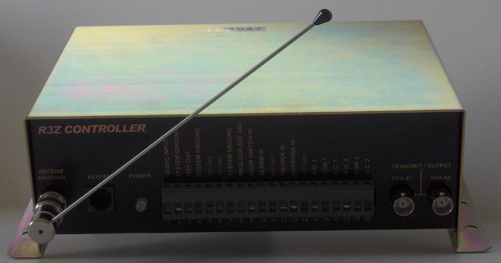
7 Controller Notes and Diagrams 7 Front Panel Connectors Figure 1: R3Z Controller Front Panel Connectors Front Panel Connector Description - Left to Right # Name Remarks Receive Antenna BNC connector for whip or elevator-style cable antenna. Do not exceed 3 feet of antenna cable. Keypad RJ-11 connector for keypad. Two keypads can be connected using a modular Y adapter (Part # AR3KA01-001) 1 +24VDC INPUT Powers the controller (250 ma), maglock (1.0A max), and +12 VDC auxiliary output (200 ma max). 2 SYSTEM GROUND Common Ground 3 +12V OUT Power for ID display, select sound, etc.: 12VDC, 200mA max 4 SYSTEM GROUND Common Ground 5 NOT USED Not used 6 NOT USED Not used 7 SYSTEM GROUND Common ground 8 MAGLOCK OUT 24V Power (24 VDC, 1.0A max) to energize a magnetic door lock while a Tag is in the detection zone. 9 DOOR SWITCH IN Active low signal (ground), activates the alarm relays and keypad alarm indicators while the door is open and a Tag is in the detection zone. Connect double door switches in series so that opening either door activates the alarm. 10 ALARM IN Activates the maglock, alarm relays, and keypad alarm indicators when connected to system ground, even if no Tag is in the detection zone. 11 NOT USED Can be used for a Tag ID Display
8 8 # Name Remarks 12 UNLOCK IN Deactivates the maglock when connected to system ground. Typically connected to fire alarm panel auxiliary trouble relay to unlock the door if a fire is detected. Also deactivates alarm relays and keypad alarm indicators. 13 OVERRIDE IN Deactivates the maglock, alarm relays, and keypad alarm indicators when connected to system ground, even if the door is open and a Tag is in the detection zone. 14 NOT USED Can be used for a Tag ID Display 15 N.O. 1 Alarm Relays 1 and 2 are activated when the door is open and a Tag is in the detection zone or when ALARM IN is 16 COM 1 connected to system ground. 17 N.C. 1 Alarm Relays 1 and 2 are deactivated when the alarm is cleared (see Mode Switch description in the table below) or OVERRIDE IN or UNLOCK IN is connected to system 18 N.O. 2 ground. 19 COM 2 Maximum relay contact current is 30 VDC. 20 N.C. 2 SRA #1 BNC connectors for two exciter antennas. Do not exceed 25 feet of RG59/U cable for each antenna. Do not terminate SRA #2 unused connector. Jumpers and Switches Layout
9 Jumpers and Switches Description Label Default Description Remarks JP102 Pos 1-2 NOT USED Do not change default setting. JP103A JP103B JP201A JP201B Pos A Pos A Relay 1 = Active TIF DO, Relay 2 = Mode Switch dependant Pos B Relay 2 mirrors Relay 1 in any mode Pos B Pos B 13V - Access Keypad Pos A 5V - RBC Panel JP202 ON ON Maglock Clamp Diode Enabled. Prevents relay contact damage caused by inductive kickback from the maglock. Will override the fast release of maglocks with that feature. OFF Maglock Clamp Diode Disabled. For maglocks with fast release feature. 9 Set this jumper OFF if the installed maglock has fast release and you want to preserve that feature. JP301 Pos 2-3 NOT USED Do not change default setting JP302 Pos 2-3 Pos 2-3 Meant for contacts that are closed when the door is closed. Pos 1-2 Meant for contacts that are closed when the door is open. JP401 OFF Not used LD501 N/A Receive indicator: lights momentarily each time a tag is detected. Flickers continuously if random RF noise signal is received. SW102 Pos 3 Controller mode switch: Pos 3 = Unlatched alarm automatically terminates SW103 SW 2 ON SW 2 ON Loiter alarm enabled SW 2 OFF Loiter alarm disabled SW201 Pos 4 Receiver threshold switch: adjust for optimum noise suppression and tag reception. 0 = OFF, receiver disabled 1 = low sensitivity, high noise suppression 7 = high sensitivity, low noise suppression 8, 9 = highest sensitivity, no noise suppression R520 N/A Exciter antenna adjust: controls the power of the exciter field. Turn clockwise to increase the field power and detection zone size. POWER (on front panel) OFF no power to controller. Solid green Normal operation Located at the upper left of the board, used for testing receive antenna reception during installation. See Mode Switch (SW102) Settings and Relay Action on page 10. SW 1 is not used. Do not set a detection zone larger than 10 feet.
10 10 Mode Switch (SW102) Settings and Relay Action Relay Action Position Description Relay 1 Relay , A-F Notes: Test mode. Use only while testing during installation or troubleshooting. No action No action Non-latched alarm Active TIF D/O Active TIF D/O or D/C automatically terminates Latched alarm does not Active TIF D/O Active TIF D/O or D/C terminate Non-latched alarm Active TIF D/O TIC automatically terminates Latched alarm and pre-alarm Active TIF D/O TIC Non-latched alarm Active TIF D/O Active on Bypass automatically terminates Not used. D/O = Door Open, D/C = Door Closed TIF = Tag In Field (in exciter detection zone) TIC = Tag Initiated Communication (tamper) If loiter alarm is enabled on SW103, then Relay 1 engages after 55 seconds in any mode (except test) Connecting a Third-Party Keypad Third-party keypads can be connected to an R3 controller using a 6P6C modular plug according to the following pin-outs at the controller keypad jack, from left (pin 1) to right (pin 6): Pin Description +12V DC Ground BYPASS_IN RESET_IN ALARM_OUT BYPASS_OUT
11 Specifications 11 International ECO Door Controller Specifications Part Number Operating Temperature Relative Humidity Dimensions (W x H x D) Weight Operating Frequencies Input Voltage Current Draw Relay Outputs (2) CE Compliant 804A F to 131 F (0 C to 55 C) 0-90% RH non-condensing Door Controller: 7 x 9.5 x 3 (17.8 x 24.1 x 7.6 cm) Exciter Ant.: 13 L x 2.5 W x 1.5 H (33 x 6.3 x 3.8 cm) Height with surface mount cover: 1.7 (4.5cm) Access Keypad: 4.5 x 2.75 x 2.5 (11.4 x 6.9 x 6.4 cm) 46 oz (1300 g) approx. (controller only) Input: MHz; Output: 125 KHz A Door Controller: 300 ma 12 V Output: 200 ma Maglock Output: 1000 ma 2 A, 30 VDC Form C dry contact Yes
12 12 Notes:
13 Stanley Security Solutions Inc. Stanley Healthcare Solutions Division 1550 N. 20th Circle Lincoln, NE Telephone: USA: Canada: Int l: +1 (613) Web site: Stanley Security Solutions Inc. All Rights Reserved. February Rev A.
Section 1: General Description. Section 2: Features. Section 3: Operation. CM-RQE70 PIR REQUEST TO EXIT DETECTOR Installation Instructions.
 CM-RQE70 PIR REQUEST TO EXIT DETECTOR Installation Instructions 1 PACKAGE CONTENTS Wiring Harness 6 Wire Nuts #6 x 3/4 Screws s BP7175 3/16 Wall Plugs Section 1: General Description Camden CM-RQE-70 Request-to-Exit
705 Emmett Street Bristol, CT DynaLock MODEL 3101C-TJ101 DELAY EGRESS SYSTEM WIRING INSTRUCTIONS
 BASIC SET-UP 1. Remove the Electronics Cover to expose the circuit board assembly. C L C 2. - System Selector Switches The selector switches (S3) which control major system functions are factory set to
CM-RQE70A PIR REQUEST TO EXIT DETECTOR
 Door Activation Devices CM-RQE70A PIR REQUEST TO EXIT DETECTOR THIS PACKAGE INCLUDES (2) #6 x 3/4" Screws (2) 3/16" Wall Plugs (2) MOV's BP7175 1. GENERAL DESCRIPTION Camden CM-RQE70A Request-to-Exit Sensor
ATS1235 Advanced Wireless DGP on 868 MHz AM Installation Sheet
 ATS1235 Advanced Wireless DGP on 868 MHz AM Installation Sheet EN 1 2 1 3 2 4 1 5 12V 6 2 0V D+ D- CON3 7 CON1 ON 3 1 2 3 4 1234 8 3 4 1 0 ON 1 2 3 4 METAL METAL Address 1 1 0 ON 1 2 3 4 Address 2 2011
Model SWH-3000 Proximity Multi-Frequency 125KHz & 13.56MHz (Fixed) Reader Installation Guide. Version A0 Part Number UM-102 September 2005
 Reader Installation Guide. Version A0 Part Number UM-102 September 2005") Model SWH-3000 Proximity Multi-Frequency 125KHz & 13.56MHz (Fixed) Reader Installation Guide Version A0 Part Number UM-102 September 2005 1 CONTENTS Introduction................................................
Model SWH-3000 Proximity Multi-Frequency 125KHz & 13.56MHz (Fixed) Reader Installation Guide Version A0 Part Number UM-102 September 2005 1 CONTENTS Introduction................................................
CM-RQE70 PIR REQUEST TO EXIT DETECTOR
 Door Activation Devices CM-RQE70 PIR REQUEST TO EXIT DETECTOR THIS PACKAGE INCLUDES (1) Wiring Harness (2) #6 x 3/4" Screws (2) 3/16" Wall Plugs (6) Wire Nuts (2) 's BP7175 1. GENERAL DESCRIPTION Camden
Model SWH-4000 Multi-Technology Mullion 125 KHz and MHz (Flex) Reader Installation Guide. Version A0 Part Number UM-104 September 2005
 Reader Installation Guide. Version A0 Part Number UM-104 September 2005") Model SWH-4000 Multi-Technology Mullion 125 KHz and 13.56 MHz (Flex) Reader Installation Guide Version A0 Part Number UM-104 September 2005 1 CONTENTS Introduction................................................
Model SWH-4000 Multi-Technology Mullion 125 KHz and 13.56 MHz (Flex) Reader Installation Guide Version A0 Part Number UM-104 September 2005 1 CONTENTS Introduction................................................
STATUS ALARM ALARM HISTORY POWER HISTORY RESET
 Instruction Manual Model 1582-70L2 RF Switch June 2011, Rev. D CH1 AUTO CH2 SWITCH 1 2 1 2 STATUS 1 2 MODEL 1582 SWITCH CROSS TECHNOLOGIES INC. CH1 ONLINE MANUAL SELECT CH2 SWITCH MANUAL REMOTE ONLINE
RCR-REX Request-to-Exit Dual Technology Motion Sensor Installation Guide
 RCR-REX Request-to-Exit Dual Technology Motion Sensor Installation Guide Introduction This is the Interlogix RCR-REX Request-to-Exit Dual Technology Motion Sensor Installation Instructions for models RCR-REX-W,
Installation Instructions
 Request-to-Exit Dual Technology Motion Sensor 1048889B November 2005 Copyright 2005, GE Security Inc. Introduction This is the GE Request-to-Exit Dual Technology Motion Sensor for models -W, -B, and -G.
RONDISH DoorWatcher EASY INSTALL STRIP DOOR MONITOR
 Rondish UI v.04 RONDISH DoorWatcher EASY INSTALL STRIP DOOR MONITOR ( For Curbell only) USER INSTRUCTION Issued 13 June 2017 CONTENTS 1. EQUIPMENT DESCRIPTION 2. INSTALLATION 3. PROGRAMMING AND SETTING
All-In-One Wireless Security System V1.0. Model #: MG-6060
 All-In-One Wireless Security System V1.0 Model #: MG-6060 Reference and Installation Manual DRAFT Table of Contents Introduction... 5 About Magellan and this Manual... 5 Conventions... 5 Specifications...
EVO192 v3.0 Fire and Burglary What s New
 EVO192 v3.0 Fire and Burglary What s New Compatibility: EVO192 v3.0 TM50 v1.31 K641 v2.41 Overview: CP-01 Compliancy Wiring Diagram The following sections/options have been added to the EVO192 panel. They
Long Range Radio Alarm Transmitter
 TM Long Range Radio Alarm Transmitter INSTALLATION MANUAL Version 1.3W FEATURES Transmits alarm information to a long range radio network Varitech Transmission Format Note: If automatic SIA is used in
All-In-One Wireless Security System V3.2 Programming Guide. Model # MG6130 / MG6160
 All-In-One Wireless Security System V3.2 Programming Guide Model # MG6130 / MG6160 We hope this product performs to your complete satisfaction. Should you have any questions or comments, please visit www.paradox.com
PD154 & PD158 VIGILANTE II ANNUNCIATORS Instruction Manual
 PD154 & PD158 VIGILANTE II ANNUNCIATORS 8 Field Selectable Sequences All Common ISA Sequences 4 or 8-Point (Channel) Monitoring Free Replaceable Message Labels Type 4X, NEMA 4X, IP65 Front Universal Power
METEOROLOGICAL INSTRUMENTS
 METEOROLOGICAL INSTRUMENTS INSTRUCTIONS WIND TRACKER MODEL 06206 R.M. YOUNG COMPANY 2801 AERO PARK DRIVE, TRAVERSE CITY, MICHIGAN 49686, USA TEL: (231) 946-3980 FAX: (231) 946-4772 WEB: www.youngusa.com
ACSI AO ELECTRIC LATCH RETRACTION CONTROLLER INSTALLATION INSTRUCTIONS I.D. 1089, REV. F
 II 1400-2 ACSI 1406-04-AO ELECTRIC LATCH RETRACTION CONTROLLER INSTALLATION INSTRUCTIONS I.D. 1089, REV. F INSTALLATION Transformer Model BE31763001 by Basler Electric, Transformer Model 2010028 by Galaxy
All-In-One Wireless Security System V1.0. Model #: MG Reference and Installation Manual
 All-In-One Wireless Security System V1.0 Model #: MG-6060 Reference and Installation Manual Table of Contents Introduction... 3 About Magellan and this Manual... 3 Conventions... 3 Specifications... 3
Wireless D.I.Y. Alarm Kit
 Wireless D.I.Y. Alarm Kit User Manual December 2010 MAMI 21 Hubert Mathew Road Illiondale 1610 Tel: +27 11 452 4737 Email: sales@mami.co.za page 2/10 General The Wireless DIY kit, is a pre-programmed,
Long Range Radio Alarm Transmitter
 W A R N I N G Please refer to the System Installation Manual for information on limitations regarding product use and function and information on the limitations as to liability of the manufacturer. TM
STATUS ALARM HISTORY ALARM RESET
 Instruction Manual Model 1582-42L Data Switch February 1999, Rev 0 CH1 AUTO CH2 SWITCH 1 2 1 2 STATUS 1 2 MODEL 1582 SWITCH CROSS TECHNOLOGIES INC. CH1 ONLINE MANUAL SELECT CH2 ONLINE SWITCH RESET MAN
Operating instructions 2-channel code lock. Item No
 Operating instructions 2-channel code lock Item No. 1560346 Table of contents Page 1. Introduction...4 2. Explanation of symbols...4 3. Intended use...5 4. Delivery content...5 5. Safety instructions...6
MODEL ZAC ZONE ANNUNCIATOR/CONTROLLER DESIGNED FOR ZONE ANNUNCIATION AND MONITORING
 MODEL ZAC-32 32 ZONE ANNUNCIATOR/CONTROLLER DESIGNED FOR ZONE ANNUNCIATION AND MONITORING 32 HARD WIRED ZONES CAN BE NORMALLY-OPEN OR NORMALLY-CLOSED ZONE WIRING RUNS CAN BE AS FAR AS 10,000 FEET FROM
Installation and ZONES: Operation Manual. Model: ON STI-34108
 N.O. COM N.C. + 12 V - IN + 12 V - OUT 500 ma 300 ma PLUG IN ADAPTER 12 V 500mA Trigger Output 12 V 75mA N.O. COM N.C. + 12 V - IN + 12 V - OUT 500 ma 300 ma PLUG IN ADAPTER 12 V 500mA Trigger Output 12
Public Safety DAS Annunciator Panel
 Public Safety DAS Annunciator Panel 120 VAC Models: 1221-A, 1221-B, 1221-C Revision D 91117 48 VDC Models: 1221-A-48, 1221-B-48, 1221-C-48 24 VDC Models: 1221A-24, 1221-B-24, 1221-C-24 CAUTION: (Read This
Installation and Operation Manual. Model: STI TRIGGERED OUTPUT PLUG 12VDC, 75mA, 3 SEC. EMBOSSED PROGRAMMING
 EMBOSSED PROGRAMMING SWITCHES 1-8 ANTENNAS ZONES: LEFT BUTTON CALL Embossed Programming Instructions: Installation and Operation Manual STI 8-Channel 1 - MIRROR MASTER OFF/ON RIGHT BUTTON FRONT COVER RESTORE
Pioneer-R16 Gas Monitor Operator s Manual
 Pioneer-R16 Gas Monitor Operator s Manual Edition 7/2/97 RKI INSTRUMENTS, INC RKI Instruments, Inc. 33248 Central Ave, Union City, CA 94587 (510) 441-5656 Chapter 1: Description About the Pioneer-R16 Gas
Rev D 3/20/17
 Rev D 3/20/17 Installation and Operating Instructions ADAEZ Wireless Interface Module (WIM) Note Changes or modifications not expressly approved by the party responsible for compliance could void the user
DE5300 Delayed Egress System. General Information
 *911031-00* 911031-00 Wiring and Configuration DE5300 Delayed Egress System Installation Instructions General Information The Von Duprin DE5300 is designed for controlled egress applications when used
APS-300 SERIES DUAL VOLTAGE UL 294 LISTED ACCESS CONTROL POWER SUPPLIES
 APS-300 SERIES DUAL VOLTAGE UL 294 LISTED ACCESS CONTROL POWER SUPPLIES POWER SUPPLY AND BATTERY CHARGER AC AND DC STATUS INDICATORS ENOUGH POWER TO SUPPORT UP TO 3 MAGLOCKS OR ELECTRIC STRIKES PLUS REQUIRED
AMC-RAM-4. Refrigerant Alarm Module USER MANUAL. Please read the installation and operating instructions completely and carefully before starting.
 AMC-RAM-4 Refrigerant Alarm Module USER MANUAL IMPORTANT: Please read the installation and operating instructions completely and carefully before starting. Filename: 3310405B, DOC, AMC_RAM4_Manual.doc
Instruction Manual Model L2 RF Switch
 Instruction Manual Model 1582-22L2 RF Switch November 2015, Rev. A CH1 AUTO CH2 SWITCH 1 2 1 2 STATUS 1 2 MODEL 1582 SWITCH CROSS TECHNOLOGIES INC. CH1 ONLINE MANUAL SELECT CH2 SWITCH MANUAL REMOTE ONLINE
Product Manual SZ1145
 Product Manual SZ114 General Purpose Monitor Communicating Controls Description The SZ114 is a microprocessor-based monitoring and alarm interface designed to monitor up to four 1000 Ω platinum temperature
3226 Trunk Port FXO Doorphone
 3226 Trunk Port FXO Doorphone Installation and User Guide Algo Communication Products Ltd., Burnaby, BC Canada V5J 5L2 www.algosolutions.com - 1 - Document #: 90-00040F Important Safety Notice The 3226
MICROtrac MICROPROCESSOR BASED WATER TREATMENT CONTROLLER. Installation and Operation Manual REV. L
 MICROtrac MICROPROCESSOR BASED WATER TREATMENT CONTROLLER Installation and Operation Manual MICROtrac Warranty Pulsafeeder, Inc. warrants MICROtrac control systems (including the conductivity sensor) of
Digital Thermometer with Ice Alert and Clock
 Digital Thermometer with Ice Alert and Clock Model: RAR381 USER MANUAL Specifications... 8 About Oregon Scientific... 8 EU-Declaration of Conformity... 9 FCC Statement... 9 Declaration of Conformity...
STATUS ALARM ALARM HISTORY POWER HISTORY RESET
 Instruction Manual Model 1582-152 RF Protection Switch November 2009, Rev B. CH1 AUTO CH2 SWITCH 1 2 1 2 STATUS 1 2 MODEL 1582 SWITCH CROSS TECHNOLOGIES INC. CH1 ONLINE MANUAL SELECT CH2 SWITCH MANUAL
Voice Module Installation Guide. For use with ProSYS 16, ProSYS 40, ProSYS 128
 Voice Module Installation Guide For use with ProSYS 16, ProSYS 40, ProSYS 128 Important Notice This guide is delivered subject to the following conditions and restrictions: This guide contains proprietary
Independent Zone Control (I.Z.C.)
") Operation and Installation Guide Independent Zone Control (I.Z.C.) DELAYED INSTANT ARMED 1 2 3 4 7 5 6 8 9 * * fi Radionics R D279A Operation & Installation Guide 46456B Page 2 Copyright 2000 Radionics
Operation and Installation Guide Independent Zone Control (I.Z.C.) DELAYED INSTANT ARMED 1 2 3 4 7 5 6 8 9 * * fi Radionics R D279A Operation & Installation Guide 46456B Page 2 Copyright 2000 Radionics
Dec Wirsbo CoSy Radio. Installation and Operating Instructions
 Dec. 2002 Wirsbo CoSy Radio Installation and Operating Instructions Contents 1. Overview... 3 2. Room thermostat... 3 2.1 Thermostat models... 3 2.2 Function... 4 2.3 Positioning... 4 2.4 Setting and limiting
Hugs Product Guide Specification
 Stanley Healthcare Solutions 309 Legget Drive Ottawa, ON K2K 3A3, Canada Tel: 1.866.559-6275 Int l: +1 (613) 592.6997 Fax: (613) 592.4296 Web site: www.stanleyhealthcare.com E-mail: hugssupport@stanleyworks.com
Installation & Operations Manual
 Installation & Operations Manual WanderPro Management System Made in the USA 3 Year Warranty N56W24720 N. Corporate Circle Sussex, WI 53089 800-451-1460 www.rathcommunications.com RP8500WP Ver. 1 12/18
AL400ULACM AL600ULACM - 4 amp - 12VDC or 6 amp. - Fused Outputs - Fused Outputs
 ACM Series Access Power Controllers with Power Supplies Installation Guide Models Include: AL400ULACM AL600ULACM - 12VDC @ 4 amp - 12VDC or 24VDC @ 6 amp. or 24VDC @ 3 amp - Fused Outputs - Fused Outputs
WM3000 WIRELESS MODULES
 WM3000 WIRELESS MODULES $$:05 $$:07 INSTALLATION INSTRUCTIONS Table of Contents Installation... 3 Mounting Instructions & Connections... 3 Setting the Dip Switches... 4 Setting the Recognition Time...
WD-CS. Water leak detection cable. Technical Overview. Features. Page 1. Data Sheet Ref: Issue: 5.1.
 Data Sheet Ref: 90501085 WD-CS Water leak detection cable Technical Overview The WD-CS range of cable sensors are typically used to detect water leaks usually under floors, and are used in conjunction
4 & 8-POINT ANNUNCIATORS Instruction Manual
 4 & 8-POINT ANNUNCIATORS Instruction Manual 8 Field Selectable Sequences All Common ISA Sequences 4 or 8-Point (Channel) Monitoring Free Replaceable Message Labels Type 4X, NEMA 4X, IP65 Front Universal
Installation Manual Version 1.3. Long Range RF Transmitter. How to contact us:
 How to contact us: Technical Support If you have questions or problems when using this product, you can call Technical Support. If you are within the United States or Canada, you can get support by dialing
MAINTENANCE & TROUBLESHOOTING GUIDE LEAK ALARM CHANNEL DRY OIL WATER AUX ALARM HIGH LOW CRITICAL WATER TANK LEVEL ALARM MODEL LDE-740 ADVANCE PAPER
 PNEUMERCATOR Liquid Level Control Systems Electronic Systems Excluding LC2000 And TMS Series MAINTENANCE & TROUBLESHOOTING GUIDE 400 300 500 FUEL LEVEL LEAK MONITOR 1 200 600 OIL/GAS NORMAL WATER PNEUMERCATOR
Product Manual SZ1144
 Product Manual SZ1144 Refrigeration Temperature Monitor Communicating Controls Description The SZ1144 is a microprocessor-based monitoring and alarm interface designed to monitor up to four 1000 Ω platinum
RMS/RPX Reader. User Manual
 RMS/RPX Reader User Manual Copyright Disclaimer Trademarks and patents Intended use FCC compliance Copyright 2005, GE Security Inc. All rights reserved. This document may not be copied or otherwise reproduced,
GJD OPAL RFX WIRELESS 35 METRE EXTERNAL PIR INSTALLATION MANUAL
 GJD OPAL RFX WIRELESS 35 METRE EXTERNAL PIR INSTALLATION MANUAL A WIRELESS PASSIVE INFRARED DETECTOR AND THREE CHANNEL RECEIVER THAT SIMULTANEOUSLY OR INDIVIDUALLY CONTROLS CCTV SWITCHERS, VIDEO RECORDERS
JUMPERS. JP3 (Scan Lock Select) JP4 (Antenna Scan Select) JP1 (Tx Frequency Select) JP5 (Supervise Interval Select) JP2 (Gain Boost)
 JP4 (Antenna Scan Select) JP1 (Tx Frequency Select) JP5 (Supervise Interval Select) JP2 (Gain Boost)") Installation Manual Appendix B-1 JUMPERS This section contains the functions and default positions of all 16 jumpers within the Controller. Refer to Figure B.1 for a Jumper-only Controller PCB graphic.
Installation Manual Appendix B-1 JUMPERS This section contains the functions and default positions of all 16 jumpers within the Controller. Refer to Figure B.1 for a Jumper-only Controller PCB graphic.
EAS System RX Tuning Specification
 EAS System RX Tuning Specification 1 1. Basic Description, Receiver Electronics The receiver board consists of: -Signal Receiving and Disposing Part -Power / Alarm Part 1.1 Signal Receiving and Disposing
GasScanner 8C. Eight Channel Monitor. Operator s Manual. MINT-0281-XX Rev. A 01/29/08
 GasScanner 8C Eight Channel Monitor Operator s Manual MINT-0281-XX Rev. A 01/29/08 Product Warranty Matheson Tri-Gas, Inc., warrants gas alarm equipment sold by us to be free from defects in materials,
Long Range Radio Alarm Transmitter
 TM Long Range Radio Alarm Transmitter INSTALLATION MANUAL Version 1.3 This manual is for the LINKS2150 software version 1.3 TABLE OF CONTENTS FEATURES 1 Keypad Programmable... 1 EEPROM Memory... 1 Static/Lightning
120 VOLT POTENTIAL PRESENT. MAKE SURE POWER INPUT TO UNIT IS TURNED OFF DURING INSTALLATION AND WIRING PROCEDURE.
 00000 (0) 00 PowerMatic Low Energy Power Operator Wiring Instructions 0 VOLT POTENTIAL PRESENT. MAKE SURE POWER INPUT TO UNIT IS TURNED OFF DURING INSTALLATION AND WIRING PROCEDURE. REQUIREMENTS: U.L.
Remote Chexit Module (RCM) System. General Information
 System. General Information") *911032-00* 911032-00 Wiring and Configuration Remote Chexit Module (RCM) System Installation Instructions General Information The Von Duprin RCM is designed for controlled egress applications. It meets
*911032-00* 911032-00 Wiring and Configuration Remote Chexit Module (RCM) System Installation Instructions General Information The Von Duprin RCM is designed for controlled egress applications. It meets
Installation Manual. Wiegand Interface Unit Four-State (WIU-4) North America T F Asia T F
 North America T F Asia T F") North America T 888 437 3287 F 561 998 6224 Asia T 65 639 19314 F 65 639 19306 Wiegand Interface Unit Four-State (WIU-4) Installation Manual Australia T 61 3 9239 1200 F 61 3 9239 1299 Canada T 800 267
North America T 888 437 3287 F 561 998 6224 Asia T 65 639 19314 F 65 639 19306 Wiegand Interface Unit Four-State (WIU-4) Installation Manual Australia T 61 3 9239 1200 F 61 3 9239 1299 Canada T 800 267
SMARTWALK DEMENTIA WANDERING SYSTEM
 A division of NESS CORPORATION PTY LTD SMARTWALK DEMENTIA WANDERING SYSTEM SWD Door Responder SWD Resonator SWD-PET (Sold Separately) SWD-PET-BAND (Sold Separately) INSTALLATION MANUAL 1. CONTENTS 1. CONTENTS...1
Alarm Tone Generator Model AG17
 Alarm Tone Generator Installation & Operation P005089 Rev. C 150930 9/30/2015 12:25 PM Ph: 403.258.3100 \ email:info@guardiantelecom.com \ www.guardiantelecom.com Table of Contents Package Contents...
SOFTWARE VERSION 2.20 CONTROL PANEL RESET: Installer lock must be unlocked. (Address 255: enter any value other than 147)
") -961112-0003 SOFTWARE VERSI 2.20 CTROL PANEL RESET: Installer lock must be unlocked. ( 255: enter any value other than 147) Power down reset (1) Remove battery and AC to power down the unit. (4) Wait 3
-961112-0003 SOFTWARE VERSI 2.20 CTROL PANEL RESET: Installer lock must be unlocked. ( 255: enter any value other than 147) Power down reset (1) Remove battery and AC to power down the unit. (4) Wait 3
Auto Dialer. Manual E-921APQ E-921GPQ
 Troubleshooting: Auto dialer will not arm/disarm Auto dialer will not dial out Unit doesn t respond to a call-back Difficulty in activating room monitor by telephone remote control Make sure that you have
Installation and user manual for the CF5000, MF5000 and FXP5000 range of fire panels
 CF5000, MF5000 and FXP5000 Installation and user manual for the CF5000, MF5000 and FXP5000 range of fire panels 16 zone panels Contents PANEL INSTALLATION...3 Installation...3 PANEL WIRING... 3 Mains power
CabLite Luminous Auto Light Control Installation Manual
 CabLite Luminous Auto Light Control Installation Manual REV: 1.1 DATE: 1/17/2018 MANUAL NUMBER: 29 Electronic Controls Inc 7073 North Atlantic Ave Cape Canaveral, FL 32920 WWW.ECIAMERICA.COM REV DATE DESCRIPTION
METEOROLOGICAL INSTRUMENTS
 METEOROLOGICAL INSTRUMENTS INSTRUCTIONS WIND TRACKER MODEL 06206 R.M. YOUNG COMPANY 2801 AERO PARK DRIVE, TRAVERSE CITY, MICHIGAN 49686, USA TEL: (231) 946-3980 FAX: (231) 946-4772 WEB: www.youngusa.com
Operating Instructions
 D-TEK PCB-1 Vehicle Loop Detector Operating Instructions This product is an accessory or part of a system. Always read and follow the manufacturer s instructions for the equipment you are connecting this
C-Bus PIR Occupancy Sensor. Installation Instructions 5751L
 C-Bus PIR Occupancy Sensor Installation Instructions 5751L Contents 1.0 Description 3 2.0 Important Notes 3 3.0 Installation 3 4.0 C-Bus Network Connection 6 5.0 Programming and Setup 7 6.0 Troubleshooting
MODEL 5800A CARBON MONOXIDE (CO) MONITOR AND ALARM SAMPLE-DRAWING TYPE
 MONITOR AND ALARM SAMPLE-DRAWING TYPE") MODEL 5800A CARBON MONOXIDE (CO) MONITOR AND ALARM SAMPLE-DRAWING TYPE 11//07 A153-021500-1 INSTRUCTION MANUAL - MODEL 5800A CO ALARM I INTRODUCTION This MST Model 5800A Carbon Monoxide (CO) Alarm is a
MODEL 5800A CARBON MONOXIDE (CO) MONITOR AND ALARM SAMPLE-DRAWING TYPE 11//07 A153-021500-1 INSTRUCTION MANUAL - MODEL 5800A CO ALARM I INTRODUCTION This MST Model 5800A Carbon Monoxide (CO) Alarm is a
PROGRAMMING GUIDE SPECTRA CONTROL PANELS V , 1725EX, 1728 AND 1728EX 1755, 1755EX, 1758, AND 1758EX
 PROGRAMMING GUIDE SPECTRA CONTROL PANELS V1.2 1725, 1725EX, 1728 AND 1728EX 1755, 1755EX, 1758, AND 1758EX TABLE OF CONTENTS HOW DO I PROGRAM THE SYSTEM?... 4 Single Digit Data Entry Method (Hexadecimal
WatchDog Wireless Crop Monitor Operation Manual
 WatchDog Wireless Crop Monitor Operation Manual Spectrum Technologies, Inc. CONTENTS General Overview 3 Accessories 4 System Configuration 5 Configuring the Monitoring Unit 7 Powering Up the Unit 7 LED
QUICKFIT INSTALL HOOK-UP SHEET FOR ESL KIT REV 1.17 OP
 QUICKFIT INSTALL HOOK-UP SHEET FOR ESL KIT REV 1.17 OP PROGRAMMING STARTS Entering Installer mode If you want to get into program mode press followed by your installer code, default set to 000000
Operating Instructions
 LP D-TEK Vehicle Loop Detector Operating Instructions This product is an accessory or part of a system. Always read and follow the manufacturer s instructions for the equipment you are connecting this
E-PLEX 5x70 Series Stand-Alone Access Controller. Installation Instructions
 E-PLEX 5x70 Series Stand-Alone Access Controller Installation Instructions 1 Table of Contents STEP...PAGE Tools Required... 2 A-1 Wall Installation...4 A-2 Gang Box Installation... 5 B-1 System Components...6
Pella Insynctive Product Guide
 Pella Insynctive Product Guide Sensor Details and Setup for Compatible Home Automation Systems Bridge Integrated Entry Door Sensor Integrated Patio Door Sensor Integrated Window Sensor Universal Window
D-Tect 2 GJD300 Quad PIR Movement Detector
 D-Tect GJD0 Quad PIR Movement Detector Package Contents 3. Package Contains: x D-Tect x Drilling template for fixing holes x Allen Key 3 x 3.75mm wall plugs 3 x 3.75mm screws x Spare Sliding Curtains x
Models NFPA 1221-A, NFPA 1221-B Public Safety DAS Annunciator Panel. Revision E 61117
 Models NFPA 1221-A, NFPA 1221-B Public Safety DAS Annunciator Panel Revision E 61117 CAUTION: (Read This First) This panel has been designed to make it nearly bullet proof to mistakes made when wiring
AIM TECHNICAL MANUAL PATENT PENDING STOP REMEMBER TO ACTIVATE UNIT BEFORE TESTING. See page 9 for Activation Instructions
 AIM TECHNICAL MANUAL AIM-1450WL WIRELESS PATENT PENDING STOP REMEMBER TO ACTIVATE UNIT BEFORE TESTING See page 9 for Activation Instructions AIM Technical Manual - AIM 1450WL AIM-1450WL WIRELESS ABOUT
MVP-D-TEK Vehicle Loop Detector 9 Volts DC to 240 Volts AC. Operating Instructions
 MVP-D-TEK Vehicle Loop Detector 9 Volts DC to 240 Volts AC Operating Instructions We have designed the new MVP-D-TEK vehicle loop detector with the following objectives in mind: 1. Compact package to allow
Installation Guide for AL300ULM. Multi-Output Access Control Power Supply Charger
 Installation Guide for AL300ULM Multi-Output Access Control Power Supply Charger R AL300ULM - Multi-Output Access Control Power Supply/Charger Overview: The AL300ULM multi-output access control power supply/charger
! "! # Please read these installation and operating instructions completely and carefully before starting.
 ! "! # $% Please read these installation and operating instructions completely and carefully before starting. File name:3009405d Revised,20/10/2008 Copyright, July 2004 The Armstrong Monitoring Corporation
SOFTWARE VERSION 2.20 CONTROL PANEL RESET:
 -961112-0002 SOFTWARE VERSI 2.20 CTROL PANEL RESET: Installer lock must be unlocked. ( 255: enter any value other than 147) Power down reset (1) Remove battery and AC to power down the unit. (4) Wait 3
D-TEK O P E R A T I N G I N S T R U C T I O N S V E HI C L E L O O P DETECTOR Johnston Parkway, Cleveland, Ohio 44128
 O P E R A T I N G I N S T R U C T I O N S D-TEK V E HI C L E L O O P DETECTOR 4564 Johnston Parkway, Cleveland, Ohio 44128 P. 800 426 9912 F. 216 518 9884 Sales Inquiries: salessupport@emxinc.com Technical
DS9370-BEL. Installation Instructions TriTech Ceiling Mount PIR/Microwave Intrusion Detector
 DS970-BEL EN Installation Instructions TriTech Ceiling Mount PIR/Microwave Intrusion Detector DS970-BEL Installation Instructions.0 Installation Considerations.0 Installation Considerations Not suitable
! WARNING To avoid risk of electrical shock, personal injury or death; disconnect power to range before servicing, unless testing requires power.
 Technical Information Electric Slide-In Range JES8850BC* JES9900BC* JES9860BC* Due to possibility of personal injury or property damage, always contact an authorized technician for servicing or repair
Long-Range Barrier Sensors
 Troubleshooting: Receiver LED never turns ON and the buzzer never sounds Buzzer does not sound if the sensor is triggered Receiver LED is ON and the buzzer sounds all the time Test the power and ground
! WARNING To avoid risk of electrical shock, personal injury or death; disconnect power to range before servicing, unless testing requires power.
 Technical Information Electric Downdraft Slide-In Range JES9800BA* JES9900BA* Due to possibility of personal injury or property damage, always contact an authorized technician for servicing or repair of
Any additional devices linked to the system ET08 (computer, sensors, relays etc.) must be approved by LST EN standard.
 must be approved by LST EN standard.") COMMUNICATOR ET08 User Manual v1.0 Safety instructions Please read and follow these safety guidelines in order to maintain safety of operators and people around: GSM communicator (gateway) ET08 (further
COMMUNICATOR ET08 User Manual v1.0 Safety instructions Please read and follow these safety guidelines in order to maintain safety of operators and people around: GSM communicator (gateway) ET08 (further
Operations Manual. Motion Detector Module Model ZS10
 Motion Detector Module Model ZS10 The must be referred to for correct installation. Failure to comply with the shall void all warranties and liabilities. Overview The ZS10 Motion Detector Module is an
Reflective Optical Beam Smoke Detector User Guide
 Reflective Optical Beam Smoke Detector User Guide 1. Installation IMPORTANT NOTE: The infrared beam path MUST be kept clear of obstructions at all times! Failure to comply may result in the system initiating
TECHNICAL DATA SHEET CONVENTIONAL FIRE ALARM SYSTEMS Conventional Fire Alarm Control Panel
 CVENTIAL ALARM S Features: Description: The LF-CP Series Fire Alarm Control Panel is manufactured based on advanced technology while maintaining high quality during assembly. It is of solid state circuitry
HEXA PROGRAMMING: STREAMLINED SECTION PROGRAMMING
 -961212-0004 SOFTWARE VERSION 3.10 CONTROL PANEL RESET: Installer lock must be unlocked. ( 058: enter any value other than 147) Power down reset (1) Remove battery and AC to power down the unit. (2) Connect
v3 360 Dual Technology Low Voltage Occupancy Sensor with Light Level, Isolated Relay and Manual On feature
 DT-300 v3 360 Dual Technology Low Voltage Occupancy Sensor with Light Level, Isolated Relay and Manual On feature Specifications Voltage...18-28VDC/VAC, half wave rectified AC Current Consumption...25
Yale Real Living Key Free Push Button Deadbolt B1L Installation and Programming Instructions
 Yale Real Living Key Free Push Button Deadbolt B1L Installation and Programming Instructions Before you begin DOWNLOAD THE BILT APP for step-by-step installation instructions & to register your product
80 CHANNELS WIRELESS RECEIVER WITH LCD DISPLAY M1.1.1-Hx.x-F1.1-ENG [AN] [SPV] MADE IN ITALY INSTALLATION AND USE MANUAL
![80 CHANNELS WIRELESS RECEIVER WITH LCD DISPLAY M1.1.1-Hx.x-F1.1-ENG [AN] [SPV] MADE IN ITALY INSTALLATION AND USE MANUAL](/thumbs/72/67367199.jpg "80 CHANNELS WIRELESS RECEIVER WITH LCD DISPLAY M1.1.1-Hx.x-F1.1-ENG [AN] [SPV] MADE IN ITALY INSTALLATION AND USE MANUAL") RX808-LCD 80 CHANNELS WIRELESS RECEIVER WITH LCD DISPLAY 14.12-M1.1.1-Hx.x-F1.1-ENG [AN] [SPV] MADE IN ITALY INSTALLATION AND USE MANUAL WARNINGS Installation: This device must be installed only by qualified
RX808-LCD 80 CHANNELS WIRELESS RECEIVER WITH LCD DISPLAY 14.12-M1.1.1-Hx.x-F1.1-ENG [AN] [SPV] MADE IN ITALY INSTALLATION AND USE MANUAL WARNINGS Installation: This device must be installed only by qualified
INSTALLATION 125 PSI (8.6 BAR) MAXIMUM OPERATING PRESSURE
 MAXIMUM OPERATING PRESSURE") . Bulletin XL-200 INSTALLATION ADJUSTMENT SERVICE THERMOSTATIC WATER MIXING VALVE SERIES XL-200, XL-200-LF, XL-200-SW, XL-200-SW-LF IMPORTANT! Provide valve serial number, (located on valve cover) when
. Bulletin XL-200 INSTALLATION ADJUSTMENT SERVICE THERMOSTATIC WATER MIXING VALVE SERIES XL-200, XL-200-LF, XL-200-SW, XL-200-SW-LF IMPORTANT! Provide valve serial number, (located on valve cover) when
SECTION DIGITAL, ADDRESSABLE FIRE-ALARM SYSTEM
 SECTION 283111 - DIGITAL, ADDRESSABLE FIRE-ALARM SYSTEM PART 1 - GENERAL 1.1 RELATED DOCUMENTS A. Drawings and general provisions of the Contract, including General and Supplementary Conditions and Division
! WARNING To avoid risk of electrical shock, personal injury or death; disconnect power to range before servicing, unless testing requires power.
 Technical Information Electric Slide-In Range JES9750BA* JES9860BA* Due to possibility of personal injury or property damage, always contact an authorized technician for servicing or repair of this unit.
CX-29. Section 1 General Description. Section 2 Installation. Besam Switching Network & Bi-Directional Door Sequencer Installation Instructions
 CX-9 550 Timberlea Blvd., Mississauga, ON L4W T7 Telephone: 905-366-3377 Fax: 905-366-3378 Toll-Free: -877-6-3369 Web: www.camdencontrols.com Besam Switching Network & Bi-Directional Door Sequencer Installation
D-TECT 3 IP. GJD260 IP Motion Detector
 D-TECT 3 IP GJD260 IP Motion Detector PACKAGE CONTENTS 1 x D-TECT 3 IP 1 x Drilling template for fixing holes 3 x 31.75mm wall plugs 3 x 31.75mm screws 2 x Spare sliding curtains 2 x Tamper feet 1 x Tamper