EFP Series ( enhanced ) Flameproof Electrical Connectors for Hazardous Environments IP 68. Certified to: IIC
|
|
|
- Rolf Chambers
- 5 years ago
- Views:
Transcription

")


1 EFP Series ( enhanced ) Flameproof Electrical Connectors for Hazardous Environments IP 68 Certified to: IIC

2 EFP Series Flameproof Electrical Connectors EFP Series Connectors detailing a variety of pin configurations and shell hardware options ATEX the EEC's authorized ATEX representative has reviewed contents of this catalogue Elecquip

3 Contents Introduction ATEX overview Environmental Highlights Code Logic Inline Plug with Threaded Entry Inline Plug with Mechanical Clamp Inline Plug with Basket Weave Grip Inline Plug with Compression Nut Inline Receptacle with Threaded Entry Inline Receptacle with Mechanical Clamp Inline Receptacle with Basket Weave Grip Inline Receptacle with Compression Nut Panel Mount Receptacle Panel Mount Receptacle with Threaded Entry Panel Mount Receptacle with Mechanical Clamp Panel Mount Receptacle with Basket Weave Grip Panel Mount Receptacle with Compression Nut EFP Gland Selection Chart Marking and Labelling Ex Environments Protection Concepts for Electrical Apparati Safety with Temperature Classes Degrees of Ingress Protection ATEX Directives EX Connector Selection Additional EFP Connector Products Disclaimer This catalogue has been prepared with great care. Our products are always subject to improvement and testing. We reserve the right to change materials and specifications without notice. All dimensional data, materials or specifications should be confirmed by the company prior to incorporation in design or purchase specification. The company does not accept liability for loss or damage, consequential or otherwise resulting from any inaccuracies, omissions or typographical errors in this document. EFP Flameproof Connector Series Page 3

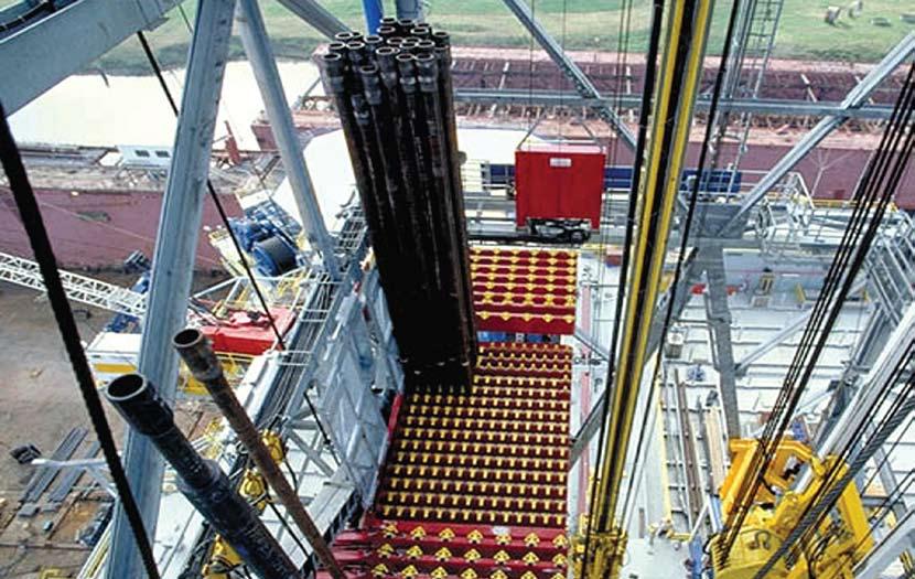
4 EFP Series Introduction The EFP Series of electrical connectors is a comprehensive line of power, control and instrumentation electrical connectors products. This series is certified for use in Zone 1 and Zone 2 classified locations with IP68 environmental sealing characteristics. EFP Series electrical connectors may be specified for use in Oil, Gas and Petro- Chemical applications, land based and offshore drilling systems and pharmaceutical grade applications. Areas of application include power, control and instrumentation circuits requiring quick and safe connection and disconnection in service. This series is also readily available, with an extensive inventory to support small or large requirements. The EFP Series of connectors are designed for use with both single and multi condutor cable types and are designed for service in the most demanding environments. The connector bodies are manufactured from hard anodised aluminium, alternative materials such as brass and stainless steel, nickel aluminium bronze and titanium are also available. EFP series connectors are designed for quick mating and unmating in service. Cable accommodations including armored and sheathed allow industrial, offshore, and petrochemical type cables to be terminated in various manners depending on cable type as well as application and regulatory requirements. Receptacles are available for panel or cable 'inline' mounting. Receptacles with a potting adaptor can be installed into either an EEx 'd' flameproof, EEx 'e' increased safety or EEx 'p' purged type enclosure systems. The contact termination methods available are solder, crimp or pressure termination depending on insert selection. Contact materials are copper alloys and various plating options are available depending on application and ampacity. Silver and gold plating, over copper contacts are standard. The EFP series lends itself to both single and multi conductor applications, with a comprehensive range of inserts to suit wire size 18 AWG(0.75mm 2 ) to 1111 MCM(563mm 2 ). Multipole power inserts are available up to 600 amperes at 1000V, Single pole power to1135 amperes at 1000V. Control and instrumentation inserts are available in 2 through 143 contacts. Composite inserts (power & control) are also readily available. For planned non intermateability connectors maybe furnished with alternate key positions andmay be color coded. EFP Series connectors share common insert configurations withe the HDS series of connectors, allowing for a complete systems integration in both hazardous and non hazardous locations. Page 4 Elecquip
.")


5 ATEX Directive Overview The EFP Connector series is certified in compliance with the ATEX Directive, European Community Directive 94/09/EC (see pages 28 and 29 for a more thorough explanation of ATEX directives). To ensure operator and equipment safety this directive covers a wide field of safety requirements including:» Integrated safely requirements» Specific conditions of inspection and maintenance» Environmental conditions» Marking» Instructions for use» Choice of materials» Design and manufacture» Potential ignition sources such as sparking, electric arcs, high surface temperatures» Explosive atmospheres caused by the presence of gas, vapours and mist» Explosive atmospheres caused by the presence of air-dust mixtures. The approval was issued by Intertek ETL SEMKO. ITS08ATEX15916X The connection system has a "component acceptance" approval number which simplifies the certification procedure of equipment to which the EFP Series can be fitted to. This means that the connector is accepted as being suitable for use on other certified Fameproof equipment. It will not be necessary to submit documentation or connector samples for repeat examination and testing when it is incorporated into new flameproof equipment designs. EEC is committed to developing the EFP series in accordance with the ATEX directive and regulatory requirements. ATEX the EEC's authorized ATEX representative has reviewed contents of this catalogue EFP Flameproof Connector Series Page 5
 Achieves IP 68-8 Clause 5.1, 5.2,13.4,14.2.7. Electrical resistence EN:60079-7 : 2003 Thermal Shock MIL-STD-1344 MIL-STD-1344 method 1003 test condition A Clause 4.")
6 Environmental Highlights Property Standard EFP Connector Series Operating Temperature MIL-STD-1344 method F to 225 F (-55 C to +125 C) Ingress Protection EN:60529:1992 Degreesof protection provided by enclosure ( IP code) Achieves IP 68-8 Clause 5.1, 5.2,13.4, Electrical resistence EN: : 2003 Thermal Shock MIL-STD-1344 MIL-STD-1344 method 1003 test condition A Clause 4.3 method 3001 meets MIL-STD-1344 method 1003 Corrosion Resistance 48 hours method 1001 MIL-STD-1344 No exposure of base material Salt Spray:336days - No exposure of base material Chemical Resistance No Requirements Oil,Most Acids and Alkalis Air Leakage 1 atmosphere meets MIL-STD-1344 method 1003 Shock Resistance Vibration MIL-STD-202 method 207 MIL-STD-1344 method 2006 Meets MIL-STD-202 method 207 Meets MIL-STD-1334 method 2006 High-Impact Resistence MIL-STD-202 method 207 EN: meets MIL-STD-202 method 207 meet IK08 joules Frequency MIL-22992E 50, 60, and 400 Hz Relavent Standards and Specifications IEC EN : 2006 MIL-C-22992E IEC EN : 2007 MIL-STD-202 IEC EN : 2003 UL CSA 1686 EN : 2006 EN : 2004 MIL-STD-1346 EN : 1995 MIL-STD-1353 EN : 1999 UL CSA 486A-B MIL-C-5015G UL CSA 1682 NEMA 250 Page 6 Elecquip
 2 Shell Type 13 - Plug 15 - Inline Receptacle 17 - Panel Mount Receptacle 4. Sealing Method Grommet I.D. 02 To 46 - Range Available (Multiples of 1/8 (0.125mm) i.e. 06=6/8 (0.")
7 Code Logic - EFP Series Product Series 1 Connector Body Material B - Brass N - Nickel Aluminum Bronze S - Stainless T - Titanium Omitted - Aluminum (STD.) 2 Shell Type 13 - Plug 15 - Inline Receptacle 17 - Panel Mount Receptacle 4. Sealing Method Grommet I.D. 02 To 46 - Range Available (Multiples of 1/8 (0.125mm) i.e. 06=6/8 (0.75mm) Potting required (Stycast 2850) or Approved cable gland Eex d, Exd e to suit cable construction 00 - Without gland, A2A to A2H for gland non armored Section E1A to E1H Armore Style (omit if no armore) AR - Armored no Sheath AS - Armored and Sheath 8 Termination Style S - Solder R - Pressure Omitted - crimp 9 Insert Orientation Omitted - Normal (STD) EFP E 1 E X A S M Cable Adapter Styles 1 - Enclosure 2 - Mechanical Clamp 3 - Threaded entry for Ex Gland 4 - Basket Weave grip 5 - Compression nut 6 - Panel Mount Adapter (Plug) 7 - NPT Mount (Receptacle) 8 - Junction Box Shielded Plug 10 - Shielded Receptacle 5 Shell Size 12 16, CB16 20, CB20 24, CB24 28, CB28 6 Insert Arrangement See Insert Section 7 Contact Gender M - Male Pin F - Female Socket 10 Color Coding Options Blk - Black R - Red Wht - white Blu - Blue G - Green Or - orange Y - Yellow B - Brown 11 Wire Length Wire or Cable length if factory assembled expressed in feet Protection Class IP68-8 Per EN:60529:1999 Temperature rating -22 o F to 265 o F (-30 o C to 25 o C) Certification CE 0359 Exd II2F T6 Tam-20 to 50+ o C Areas of use Zone classified hazardous areas Zones 1 and 2, 21 and 22 ATEX Directive 94/9/EC EN: :2006 General Requirements EN: :2007 Flameproof enclosures "d" EN: Increased safefty " e " EN :2006 General Requirements EN :2004 EFP Series Connector Selection & Wattage Calculation To select the shell size of the connector, it is necessary that a calculation of the dissipated wattage is determined. The calculation is essential to ensure that the connector arrangement, including the upper ambient temperature of the installation location, remains within the operating temperature classifiction (see pages 26 & 27 for more information). EFP Flameproof Connector Series Page 7


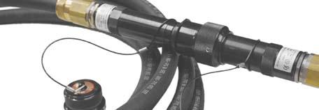
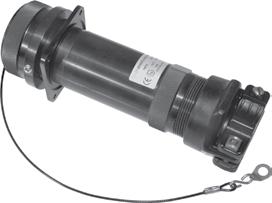
8 EFP Connector Series Features Certification Bulkhead Connector may aslo be fitted to EExecertified equipment Knurled section for assembly ease Cable Entry Options Accepts Multiple cable types depending on application and termination method Threaded Cap Interior Flameproof Barrier Strain relief method, cable gland or alternative maintains an IP 68 ingress protection and Shell ERA DTS 01 deluge test compliance One-Piece Insert With interfacial seal and isolated contact cavity Long Cable Adapter Allows for ease of termination Heavy Duty Coupling Hood IIC EN :2004, EN :2004, EN :2007, EN :2004, EN :2004 Suitable for use in Gas Groups IIA, IIB and IIC Ingress Protection nof IP66 and IP6 to IEC60529 with deluge protection to DTS01 Operating Temperature range -40 to +100 C. Temperature Class and Ambient T5 40C Optional T5 and T6 temperature classifications are available with ambient's up to 65 C Page 6 Elecquip

9 Ex Connectors Application and Features Temporary but safe connecting and disconnecting of power is critical in many industries. In order to maintain this safety requirement, Elecquip has introduced a new series of EExd Connectors that are ATEX approved, easy to use and exceptionally robust. They allow for safe and rapid service, repair and replacement of key plant, or provide quick connection to temporary equipment. Their application is beneficial in high-productivity environments where minimum interruption of service is essential. The connectors are ideal for Zone 1 and Zone 2 explosive environments commonly found in oil and gas exploration, production and process plants. However, their features also offer benefits in Zone 21 and Zone 22 explosive dust environments, or in harsh and hostile non-explosive applications. In compliance with the ATEX Directive (94/9/EC), the design retains many of the features of Elecquip's already high-quality connectors, but in addition adding innovations based on your user feedback. The heavy-duty, maintenance free stainless-steel body construction is retained, along with the acclaimed Acme mating thread: enabling quick connection whilst preventing thread binding or galling. Faster Assembly An internal sleeve provides an extended installation key way which assists connector assembly by making insertion easier and quicker, and also helps to prevent insert misalignment and potential contact damage. Impossible to Cross-mate The unique visual 5 position keying system (3 on EX16) prevents contact damage and ensures safe use by eliminating the possibility of misconnection of adjacent circuits. Fully Inspectable Flameproof Barrier The removable compound chamber technology allows direct access for visual inspection of the flameproof barrier seal and offers users the peace of mind that the connector is safe for installation into flameproof and increased safety equipment. High Reliability Contacts Each Pin and Socket is fitted with Multilam Band technology to ensure reliable low resistance connection on each coupling. Quick and Easy Fieldwiring The Pin and Socket inserts are numbered from and back to assist wiring and avoid potential termination errors. EFP Flameproof Connector Series Page 7
 3-1/16 (77.8) 3-1/4 (82.6) M50x1.5-6H 24 7-3/4 (196.9) 3-1/16 (77.8) 3-3/4 (95.2) M63x1.5-6H 28 7-3/4 (196.9) 3-1/16 (77.8) 4-1/4 (107.9) M75x1.")
10 Inline Plug with Threaded Entry EFP-13-3-XX Shell Size Dimension A B C Tread D /4 (146.1) 3-1/16 (77.8) 2-1/4 (57.1) M25x1.5-6H /4 (196.9) 3-1/16 (77.8) 2-3/4 (69.9) M40x1.5-6H /4 (196.9) 3-1/16 (77.8) 3-1/4 (82.6) M50x1.5-6H /4 (196.9) 3-1/16 (77.8) 3-3/4 (95.2) M63x1.5-6H /4 (196.9) 3-1/16 (77.8) 4-1/4 (107.9) M75x1.5-6H Notes: For "CB" length inserts, add 1/2" (12.7mm) to both dimensions "A" & "B". Protection class IP 67 Page 8 Elecquip
 3 (76.2) 20 9-3/8 (238.1) 3-1/16 (77.8) 3-1/4 (82.6) 2-1/8 (54.0) 3-3/4 (95.3) 24 9-7/16 (239.7) 3-1/16 (77.8) 3-3/4 (95.2) 2-3/16 (55.6) 4-1/2 (114.3) 28 9-1/2 (241.3) 3-1/16 (77.8) 4-1/4 (107.")
11 Inline Plug with Mechanical Clamp EFP-13-2-XX Shell Size Dimension A B C D E /4 (184.1) 3-1/16 (77.8) 2-1/4 (57.1) 2 (50.8) 2-3/8 (60.3) /16 (236.5) 3-1/16 (77.8) 2-3/4 (69.9) 2-1/16 (52.4) 3 (76.2) /8 (238.1) 3-1/16 (77.8) 3-1/4 (82.6) 2-1/8 (54.0) 3-3/4 (95.3) /16 (239.7) 3-1/16 (77.8) 3-3/4 (95.2) 2-3/16 (55.6) 4-1/2 (114.3) /2 (241.3) 3-1/16 (77.8) 4-1/4 (107.9) 2-1/4 (57.2) 5-1/8 (130.2) Notes: For "CB" length inserts, add 1/2" (12.7) to both dimensions "A" & "B". Protection class IP 67 Encapsulation required: Stycast 2850FT EFP Flameproof Connector Series Page 9
12 Inline Plug with Basket Weave Grip EFP-13-4-XX Shell Size Dimension A B C D E /2 (165.1) 3-1/16 (77.8) 2-1/4 (57.1) 1-1/2 (38.1) /2 (215.9) 3-1/16 (77.8) 2-3/4 (69.9) 2 (50.8) /2 (215.9) 3-1/16 (77.8) 3-1/4 (82.6) 2-1/2 (63.5) /2 (215.9) 3-1/16 (77.8) 3-3/4 (95.2) 3 (76.2) /2 (215.9) 3-1/16 (77.8) 4-1/4 (107.9) 3-1/2 (88.9) Notes: For "CB" length inserts, add 1/2" (12.7) to both dimensions "A" & "B". Protection class IP 67 Encapsulation required: Stycast 2850FT Page 10 Elecquip
 3-1/16 (77.8) 3-1/4 (82.6) 2-1/2 (63.5) 24 8-1/2 (215.9) 3-1/16 (77.8) 3-3/4 (95.2) 3 (76.2) 28 8-1/2 (215.9) 3-1/16 (77.8) 4-1/4 (107.9) 3-1/2 (88.9) Notes: For \"CB\" length inserts, add 1/2\" (12.")
13 Inline Plug with Compression Nut EFP-13-5-XX Shell Size Dimension A B C D E /2 (165.1) 3-1/16 (77.8) 2-1/4 (57.1) 1-1/2 (38.1) /2 (215.9) 3-1/16 (77.8) 2-3/4 (69.9) 2 (50.8) /2 (215.9) 3-1/16 (77.8) 3-1/4 (82.6) 2-1/2 (63.5) /2 (215.9) 3-1/16 (77.8) 3-3/4 (95.2) 3 (76.2) /2 (215.9) 3-1/16 (77.8) 4-1/4 (107.9) 3-1/2 (88.9) Notes: For "CB" length inserts, add 1/2" (12.7mm) to both dimensions "A" & "B". Protection class IP 67 Encapsulation required: Stycast 2850FT EFP Flameproof Connector Series Page 11
 (196.9) 3-1/16 1-1/2 (38.1) (77.8) 2-3/4 2 (50.8) (69.9) M40x1.5-6H 20 7-3/4 8-1/8 (206.4) (196.9) 3-1/16 1-1/2 (38.1) (77.8) 3-1/4 2-1/2 (82.6) (63.5) M50x1.5-6H 24 7-3/4 8-1/8 (206.4) (196.9) 3-1/16 1-1/2 (38.1) (77.8) 3-3/4 3 (76.")
14 Inline Receptacle with Threaded Entry EFP-15-3-XX Shell Size Dimension A B C Tread D /4 6-1/8 (155.6) (146.1) 3-1/16 1-1/2 (38.1) (77.8) 2-1/4 1-1/2 (57.1) (38.1) M25x1.5-6H /4 8-1/8 (206.4) (196.9) 3-1/16 1-1/2 (38.1) (77.8) 2-3/4 2 (50.8) (69.9) M40x1.5-6H /4 8-1/8 (206.4) (196.9) 3-1/16 1-1/2 (38.1) (77.8) 3-1/4 2-1/2 (82.6) (63.5) M50x1.5-6H /4 8-1/8 (206.4) (196.9) 3-1/16 1-1/2 (38.1) (77.8) 3-3/4 3 (76.2) (95.2) M63x1.5-6H /4 8-1/8 (206.4) (196.9) 3-1/16 1-1/2 (38.1) (77.8) 4-1/4 3-1/2 (107.9) (88.9) M75x1.5-6H Notes: For "CB" length inserts, add 1/2" (12.7) to both dimensions "A" & "B". Protection class IP 67 Page 12 Elecquip
 2-1/2 (63.5) 2-1/8 (54.0) 3-3/4 (95.3) 24 9-3/8 (238.1) 3 (76.2) 2-3/16 (55.6) 4-1/2 (114.3) 28 9-7/16 (239.6) 3-1/2 (88.9) 2-1/4 (57.2) 5-1/8 (130.2) Notes: For \"CB\" length inserts, add 1/2\" (12.")
15 Inline Receptacle with Mechanical Clamp EFP-15-2-XX Shell Size Dimension A B C D E /4 (184.1) 1-1/2 (38.1) 2 (50.8) 2-3/8 (60.3) /4 (235.9) 2 (50.8) 2-1/16 (52.4) 3 (76.2) /16 (236.5) 2-1/2 (63.5) 2-1/8 (54.0) 3-3/4 (95.3) /8 (238.1) 3 (76.2) 2-3/16 (55.6) 4-1/2 (114.3) /16 (239.6) 3-1/2 (88.9) 2-1/4 (57.2) 5-1/8 (130.2) Notes: For "CB" length inserts, add 1/2" (12.7) to both dimensions "A" & "B". Protection class IP 67 Encapsulation required: Stycast 2850FT EFP Flameproof Connector Series Page 13
 2-1/2 (63.5) 24 8-1/2 (215.9) 3 (76.2) 3 (76.2) 28 8-1/2 (215.9) 3-1/2 (88.9) 3-1/2 (88.9) Notes: For \"CB\" length inserts, add 1/2\" (12.7) to both dimensions \"A\" & \"B\".")
16 Inline Receptacle with Basket Weave Grip EFP-15-4-XX Shell Size Dimension A B C D E /2 (165.1) 1-1/2 (38.1) 1-1/2 (38.1) /2 (215.9) 2 (50.8) 2 (50.8) /2 (215.9) 2-1/2 (63.5) 2-1/2 (63.5) /2 (215.9) 3 (76.2) 3 (76.2) /2 (215.9) 3-1/2 (88.9) 3-1/2 (88.9) Notes: For "CB" length inserts, add 1/2" (12.7) to both dimensions "A" & "B". Protection class IP 67 Encapsulation required: Stycast 2850FT Page 14 Elecquip
 24 8-1/2 (215.9) 3 (76.2) 3 (76.2) 28 8-1/2 (215.9) 3-1/2 (88.9) 3-1/2 (88.9) Notes: For \"CB\" length inserts, add 1/2\" (12.7mm) to both dimensions \"A\" & \"B\".")
17 Inline Receptacle with Compression Nut EFP-15-5-XX Shell Size Dimension A B C D E /2 (165.1) 1-1/2 (38.1) 1-1/2 (38.1) /2 (215.9) 2 (50.8) 2 (50.8) /2 (215.9) 2-1/2 (63.5) 2-1/2 (63.5) /2 (215.9) 3 (76.2) 3 (76.2) /2 (215.9) 3-1/2 (88.9) 3-1/2 (88.9) Notes: For "CB" length inserts, add 1/2" (12.7mm) to both dimensions "A" & "B". Protection class IP 67 Encapsulation required: Stycast 2850FT EFP Flameproof Connector Series Page 15
 3-7/8 (98) M50x1.5-6g 20 4-3/4 (120.7) 2-1/2 (63.5) 2.441 (62) 3 (76.2) 4-5/8 (118) M63x1.5-6g 24 4-3/4 (120.7) 3 (76.2) 2.835 (72) 3-1/2 (88.9) 5-1/8 (130) M75x1.5-6g 28 4-3/4 (120.7) 3-1/2 (88.")
18 Panel Mount Receptacle EFP-17-1-XX Shell Size Dimension A B C D E F G /4 (120.7) 1-1/2 (38.1) (42) 2-1/4 (57.2) 3-3/8 (86) M40x1.5-6g /4 (120.7) 2 (50.8) (52) 2-5/8 (66.7) 3-7/8 (98) M50x1.5-6g /4 (120.7) 2-1/2 (63.5) (62) 3 (76.2) 4-5/8 (118) M63x1.5-6g /4 (120.7) 3 (76.2) (72) 3-1/2 (88.9) 5-1/8 (130) M75x1.5-6g /4 (120.7) 3-1/2 (88.9) (82) 4 (101.6) 5-5/8 (143) M90x1.5-6g Notes: For "CB" length inserts, add 1/2" (12.7) to both dimensions "A" & "B". Protection class IP 66, IP 67* Encapsulation required: Stycast 2850FT * consult factory for mounting details to Eex e increased safety enclosures Page 16 Elecquip
 2-5/8 (66.7) M40x1.5-6H 20 7-7/8 (200) 2-1/2 (63.5) 2.441 (62) 3 (76.2) M50x1.5-6H 24 7-7/8 (200) 3 (76.2) 2.835 (72) 3-1/2 (88.9) M63x1.5-6H 28 7-7/8 (200) 3-1/2 (88.9) 3.228 (82) 4 (101.")
19 Panel Mount Receptacle with Threaded Entry EFP-17-3-XX Shell Size Dimension A B C D E Thread F /8 (150) 1-1/2 (38.1) (42) 2-1/4 (57.2) M25x1.5-6H /8 (200) 2 (50.8) (52) 2-5/8 (66.7) M40x1.5-6H /8 (200) 2-1/2 (63.5) (62) 3 (76.2) M50x1.5-6H /8 (200) 3 (76.2) (72) 3-1/2 (88.9) M63x1.5-6H /8 (200) 3-1/2 (88.9) (82) 4 (101.6) M75x1.5-6H Notes: For "CB" length inserts, add 1/2" (12.7) to both dimensions "A" & "B". Protection class IP 67 EFP Flameproof Connector Series Page 17
 2-1/16 (52.4) 3 (76.2) 20 9-5/16 (236.5) 2-1/2 (63.5) 2.441 (62) 3 (76.2) 2-1/8 (54.0) 3-3/4 (95.3) 24 9-3/8 (238.1) 3 (76.2) 2.835 (72) 3-1/2 (88.9) 2-3/16 (55.6) 4-1/2 (114.3) 28 9-7/16 (239.")
20 Panel Mount Receptacle with Mechanical Clamp EFP-17-2-XX Shell Size Dimension A B C D E F G /4 (184.1) 1-1/2 (38.1) (42) 2-1/4 (57.2) 2 (50.8) 2-3/8 (60.3) /4 (235.9) 2 (50.8) (52) 2-5/8 (66.7) 2-1/16 (52.4) 3 (76.2) /16 (236.5) 2-1/2 (63.5) (62) 3 (76.2) 2-1/8 (54.0) 3-3/4 (95.3) /8 (238.1) 3 (76.2) (72) 3-1/2 (88.9) 2-3/16 (55.6) 4-1/2 (114.3) /16 (239.6) 3-1/2 (88.9) (82) 4 (101.6) 2-1/4 (57.2) 5-1/8 (130.2) Notes: For "CB" length inserts, add 1/2" (12.7mm) to both dimensions "A" & "B". Protection class IP 67 Encapsulation required: Stycast 2850FT Page 18 Elecquip
 2-5/8 (66.7) 2 (50.8) 20 8-1/2 (215.9) 2-1/2 (63.5) 2.441 (62) 3 (76.2) 2-1/2 (63.5) 24 8-1/2 (215.9) 3 (76.2) 2.835 (72) 3-1/2 (88.9) 3 (76.2) 28 8-1/2 (215.9) 3-1/2 (88.9) 3.228 (82) 4 (101.")
21 Panel Mount Receptacle with Basket Weave Grip EFP-17-4-XX Shell Size Dimension A B C D E F G /2 (165.1) 1-1/2 (38.1) (42) 2-1/4 (57.2) 1-1/2 (38.1) /2 (215.9) 2 (50.8) (52) 2-5/8 (66.7) 2 (50.8) /2 (215.9) 2-1/2 (63.5) (62) 3 (76.2) 2-1/2 (63.5) /2 (215.9) 3 (76.2) (72) 3-1/2 (88.9) 3 (76.2) /2 (215.9) 3-1/2 (88.9) (82) 4 (101.6) 3-1/2 (88.9) Notes: For "CB" length inserts, add 1/2" (12.7mm) to both dimensions "A" & "B". Protection class IP 67 Encapsulation required: Stycast 2850FT EFP Flameproof Connector Series Page 19
 2-5/8 (66.7) 2 (50.8) 20 8-1/2 (215.9) 2-1/2 (63.5) 2.441 (62) 3 (76.2) 2-1/2 (63.5) 24 8-1/2 (215.9) 3 (76.2) 2.835 (72) 3-1/2 (88.9) 3 (76.2) 28 8-1/2 (215.9) 3-1/2 (88.9) 3.228 (82) 4 (101.")
22 Panel Mount Receptacle with Compression Nut EFP-17-5-XX Shell Size Dimension A B C D E F G /2 (165.1) 1-1/2 (38.1) (42) 2-1/4 (57.2) 1-1/2 (38.1) /2 (215.9) 2 (50.8) (52) 2-5/8 (66.7) 2 (50.8) /2 (215.9) 2-1/2 (63.5) (62) 3 (76.2) 2-1/2 (63.5) /2 (215.9) 3 (76.2) (72) 3-1/2 (88.9) 3 (76.2) /2 (215.9) 3-1/2 (88.9) (82) 4 (101.6) 3-1/2 (88.9) Notes: For "CB" length inserts, add 1/2" (12.7mm) to both dimensions "A" & "B". Protection class IP 67 Encapsulation required: Stycast 2850FT Page 20 Elecquip
 Flats Crns A 00-16ss M16 15 3.0-8.")


23 EFP Gland Selection Chart Eex d, Eex e, Eex de. A2EX EExde IIC Compression Gland Product Code Gland Size Referance Entry Thread Metric - NPT C D Cable Details Min - Max A Overall Length E Hexagonal Details (max) Flats Crns A 00-16ss M B 00-20ss M20-1/ B1 0-20s M20-1/ B M20-1/2/3/ C 2-25 M25-3/4/ D 3-32 M32-1/11/ E 4-40 M40-11/4/11/ F 5-50 M50-11/2/ G 6-63 M63-2/21/ H 7-75 M75-21/2/ *All dimensions are in mm. Features and Benefits sheath. Harder outer seal grips the cable, giving superior cable retention and IP rating Technical Data Type Gland Material Seal Material Cable Type Sealing Area Optional Accessories Ingress Protection Operating Temperature A2EX Brass (Nickel Plated) Thermoplastic Elastomer (Silicone on request) Unarmoured Outer sheath Locknut, Shroud, Earth Tag, Adaptor / Reducer IP66/67/68-30 C TO +130 C Standards and Certification Hazardous Area CENELEC / ATEX Zone 1, 2, 21 and 22 Ex de IIC and DIP, Cat. 2 and 3, EEx de II2 GD Compliance Code CENELEC / ATEX EN50014:1997E DEMKO 01 ATEX X EN50018:2000E DEMKO 01 ATEX X EN50019:2000E DEMKO 01 ATEX X EN :1999E DEMKO 01 ATEX X EFP Flameproof Connector Series Page 21
 D Min - Max A Min - Max")

24 EFP Gland Selection Chart Eex d, Eex e, Eex de. CCG E1EX MAC EExde For Use with Armoured Cables Entry Thread Overall Hexagonal Product Gland Size Cable Details Cable Details Code Referance Metric - NPT Length Details (max) D Min - Max A Min - Max B C E Flats Crns A 00-16ss M B 00-20ss M20-1/ B1 0-20s M20-1/ B M20-1/2/3/ C 2-25 M25-3/4/ D 3-32 M32-1/11/ E 4-40 M40-11/4/11/ F 5-50 M50-11/2/ G 6-63 M63-2/21/ H 7-75 M75-21/2/ *All dimensions are in mm. Features and Benefits sheath. Harder outer seal grips the cable, giving superior cable retention and IP rating Technical Data Type Gland Material Seal Material Cable Type Sealing Area Optional Accessories Ingress Protection Operating Temperature E1EX Brass (Nickel Plated) Thermoplastic Elastomer (Silicone on request) Steel Wire, Braid, Tape Amour Inner and Outer Sheath Locknut, Shroud, Earth Tag, Adaptor / Reducer IP66/67/68-30 C TO +130 C Standards and Certification Hazardous Area CENELEC / ATEX Zone 1,2,21 and 22 Ex de IIC and DIP, Cat. 2 and 3, EExde II2 GD Compliance Code CENELEC / ATEX EN50014:1997E DEMKO 01 ATEX X EN50018:2000E DEMKO 01 ATEX X EN50019:2000E DEMKO 01 ATEX X EN :1999E DEMKO 01 ATEX X Page 22 Elecquip

25 E HDE, EFP Labelling Information Connector Labels Labels are printed from microsoft access ex-serial numbers1.mdb Data entered and stored in ex-serial numbers.xls Using Brady 3481 thermal transfer printer and the label material is metallized polyester. EFP marking and warning labels are affixed to the connector at the the time of assembly. ThIs label will clearly identify the part number, Certification type, relevent electrical performance information and the year of construction. The text, with a height of.100 inches, is printed in Times New Roman Font EFP Series Label Left Hand Thread Label IMPORTANT LEFT HAND THREAD. WRENCH FULLY TO SHOULDER. DO LED L E N TED STA T NO A M N I O E R G NO T P B E I N Z WHEN MUST WH E D I L E CAP EFP Series Product Label for Protective Covers The connector cap must include the listed warning label and the product must not be used in the application if the label is omitted or missing. ATEX Marking and Labelling II 2 G 0359 CE mark denotes manufactureres declarion of product compliance to all relevant EU directives Number of Notified Body repsonsible for EC monitoring of production quality Specific mark for Explosion Protection Equipment Group Equipment Category Defines suitability of use of Group II equipment in gas and/ dust atmospheres ATEX Certification Code Gases, Vapours, and mists to EN50014 Ex d IIC T6 Explosion Protected equipment 'E' prefix denotes compliance with CENELEC Standards in the EN :2004 Series Protection Concepts Gas Group Temperature Classification EFP Flameproof Connector Series Page 23
26 Technical Data The intent of this section of the catalogue is to identify important features that may be useful in the selection and installation of explosion protected electrical equipment. There are numerous different regulations, codes, guidelines and standards for the design, installation and maintenance of electrical and non-electrical systems for use in potentially explosive atmospheres. The type of operational facility, geographic location, operator practice, local and national legislation, authority having jurisdiction etc. will determine many of the design and installation rules permitted. A fixed or floating petroleum facility located offshore, for example, would not be designed or classified in the same manner as an onshore petrochemical facility. Potentially Explosive Atmospheres An explosive atmosphere is defined as a mixture: - Of flammable substances in the form of gases, vapors, mists, dusts or fibers - With air - Under atmospheric conditions - In which, after ignition has occurred, combustion spreads to the entire unburned mixture Area Classification (Classification of Locations) The purpose of the are classification is to provide a basis for the correct selection, installation and location of electrical and non-electrical equipment in those areas. Areas must be classified depending on the properties of the flammable vapors, liquids, gases, mists, combustible dusts or fibers that may be present and the likelihood that a flammable or combustible concentration or quantity is present. The aim of area classification is to avoid ignition of flammable releases that may occur in the operation of facilities. The intent is to reduce to an acceptable minimum level the probability of a flammable atmosphere and an ignition source occurring at the same time. CENELEC and IEC Area Classification Area classification is the division of a facility into three-dimensional hazardous areas and nonhazardous areas and the sub-division of the hazardous area into Zones. Hazardous areas may be sub-divided into three Zones as follows: Flammable Gases and Vapors Zone 0 Zone 1 Zone 2 An area in which an explosive atmosphere is constantly present, or present for long periods An area in which an explosive atmosphere is likely to occur in normal operation (about 10 hours or more per year but less than 1,000 hours per year) An area in which an explosive atmosphere is not likely to occur in normal operation and if it occurs, it will exist only for a short time (about less than 10 hours per year) Page 24 Elecquip
27 Combustible Dusts Zone 20 Zone 21 Zone 22 An area in which combustible dust, as a cloud, is present continuously or frequently during normal operation, in sufficient quantity to be capable of producing an explosive concentration of combustible dust in a mixture with air An area, in which combustible dust, as a cloud, is occasionally present during normal operation in a sufficient quantity to be capable of producing an explosive concentration of combustible dust in a mixture with air An area, in which combustible dust, as a cloud, may occur infrequently and persist for only a short period, or in which accumulations of layers of combustible dust may give rise to an explosive concentration of combustible dust in mixture with air For further information on the classification of hazardous areas, see: IEC Electrical Apparatus for Explosive Gas Atmospheres, Classification of Hazardous Areas IEC Electrical apparatus for use in the presence of combustible dust Part 3: Classification of areas where combustible dusts are, or may be, present IEC Electrical Apparatus for Explosive Gas Atmospheres, Classification PR EN Classification of areas where dusts are, or may be, present Institute of Petroleum - Model Code of Safe Practice in the Petroleum Industry, Part 15: Area Classification Code for Petroleum Installations, IP 15 Classification Society A Classification Society may also enforce requirements for the design and installation of facilities. These requirements, which are in addition to statutory requirements, may influence the design and installation of electrical systems. Classification Societies include ABS, DNV and Lloyds Register. Design and Installations of Electrical Systems for Hazardous (Classified) Areas There are numerous regulation codes, guidelines and standards for the design, selection and installation of electrical installation in potentially explosive atmospheres. These requirements are in addition to the requirements are in addition to the requirements for installations in nonhazardous areas. There are several types of protection, i.e. construction techniques, available for electrical apparatus in hazardous areas. The type of protection permitted will depend upon the applicable installation codes and rules to be adopted. The selection of electrical apparatus should be in accordance with the following: - Classification of the hazardous area - Temperature class or ignition temperature of the gas, liquid, vapors, mist, dust or fiber - Where applicable, the gas, vapor or dust classification in relation to the group or subgroup of the electrical apparatus - External influences and ambient temperatures EFP Flame Proof Connector Series Page 25
28 Ex Environments Equipment Group and Equipment Category Equipment Group Equipment Category Protection Level Hazard Gas Dust Use I Mining II Industrial M1 M2 1 2 Very High Protection High Protection Very High Protection High Protection G D G D Operable in EX atmosphere De-energized in Ex atmosphere Zones 0, 1, 2 Zones 20, 21, 22 Zones 1, 2 Zones 21, 22 NOTE: Equipment Group and Category identify the areas in which equipment may be safely used 3 Normal Protection G D Zone 2 Zone 22 Zoning Classification for Gases and Dusts Area Classification Gases Dusts Zone 0 Zone 20 Zone 1 Zone 21 Zone 2 Zone 22 Zone Criteria Present continuously or for long periods (at least 1000hrs per annum) Likely to occur in normal operation occasionally (at least 10hrs, at most 100hrs per annum) Unlikely to occur in normal operation, if it does will only be for short periods (at most 10hrs per annum) Clasasification of Hazardous Areas Hazardous areas are clssified into zones on the basis of the frequency and duration of the occurrence of a explosive atmosphere. Durations on table are typical. Zone 1 Zone 2 Zone 0 Vent Valve Page 26 Elecquip
29 Protection Concepts for Electrical Apparati Gas Grouping Temperature Classes Group Typical Hazard Maximum Safe Sparking Energy Intrinsic Safety EX ia/ib Maximum Safe Sparking Energy Terminal 10 Gas/Vapour Temperature Gas Group Temperature Class I IIA IIB IIC II Methane Propane Ethylene Acetylene All Gases More Energy Less Energy all concepts Ex d, Ex ia/ib Ex e, Ex m, Ex p, Ex o, Ex q, Ex n NOTE: Equipment sub-grouping segregates gases accordingto ease of ignitability by sparks or flames. These apply to flameproof EX d and intrinsically safe EX ia/ib equipment only Acetic Acid Acetone Acetylene Ammonia Benzene Butane Cumene Cychlohexane Ethanol Thylene Hydrogen Methane Methanol Petroleum Propane Toulene Turpentine Xylene IIA IIA IIC IIA IIA IIA IIA IIA IIA IIB IIC IIA IIA IIA IIA IIA IIA IIA T1 T1 T2 T1 T1 T2 T2 T3 T2 T2 T1 T1 T1 T1 T1 T1 T3 T1 Temperature Class Temperature class relates to the hot surface ignition temperature of a particular explosive atmosphere. It must not be exceeded by the temperature classification of the equipment intended to be used in that atmosphere. Spontaneous Ignition Temp. of the Gases (T) T6 (85 o C) Temperature Class of Equipment T5 (100 o C) T4 (135 o C) T3 (200 o C) T2 (300 o C) T1 (450 o C) Ignition Temps for Dust Dust Cloud Ignition Temperature ( o C) 85 < T < < T < < T < < T < < T < < T NOTES: Temperatures are related in o C Explosion Risk Safe for Use Aluminum Coal Dust Flour Grain Dust Methyl Cellulose Phenolic Resin Polythene PVC Soot Starch Sugar Equipment approved to the CENELEC standard have T. class based on use in an ambient of -20 o to +40 o C unless otherwise stated (ie. T amb. =35 o C) EFP Flameproof Connector Series Page 27
30 Protection Concepts (cont) Concept Symbol Icon Description Category EN Stadard Gen. Req. - Gen. Req. - EN Oil Immersion Ex o Ignition source is immersed in oil 2 EN (EN ) Pressurised Ex p Ignition source is guarded with pressurised inert gas 2 EN Poweder Filled Ex q Ignition source is immersedin sand 2 EN (EN ) Flameproof Ex d Enclosed ignition will not ignite atmosphere 2 EN Increased Safety Ex e Design excludes any incendive arcs, sparks or hot surfaces 2 EN Intrisic Safety Ex ia Ex ib Circuit keeps temperature on components at a safe level 1 2 EN (EN ) Encapsulation EX m Ignition source encased in resin 2 EN Non-Incendive Ex n Will not ignited gas in normal operation NOTE: Protection concept identifies the means by which explosion protection is achieved Associated Standards 3 EN Explosive Atmospheres, Explosion Prevention and Protection Basic concepts and methodology EN Electrical Equipment for use in potentially explosive gases, vapours andmists - associated non-concept standards Classification of hazardous areas EN Electrical installations EN Inspection and maintenance of electrical installations EN Repair and overhaul of apparti IEC Data for flammable gases and vapours IEC Electrical Apparati for use in the presence of explosive dust Protection of enclosures "td" EN Classification of areas EN Selection, installation and maintenance EN Protection by encapsulation EN New electrical equipment for vapours, mists and dusts Basic method and requirements EN Protection by constructional safety "c" EN Protection by liquid immersion "k" EN Page 28 Elecquip


31 Degree of Ingress Protection per EN:60529:1999 Protection Against Solid Foreign Objects and Access to Hazardous Parts (First Digit) Protection Against Liquids (Second Digit) Non-protected Non-Protected Non-protected 0 Non-Protected Protection of persons against access to hazardous parts inside the enclsoure 1 Protected against drops of water falling vertically 1 Protected against solid foreign objects of 50mm diamter and greater Protected against access to hazardous parts with the back of a hand 2 Protected against drops of water falling at up to 15 from the vertical 2 Protected against solid foreign objects of 12.5mm diamter and greater Protected against access to hazardous parts with a finger 3 Protected against drops of water falling at up to 60 from the vertical 3 Protected against solid foreign objects of 2.5mm diamter and greater Protected against access to hazardous parts with a tool 4 Protected against drops of water from all directions 4 Protected against solid foreign objects of 1.0mm diamter and greater Protected against access to hazardous parts with a wire 5 Protected against jets of water from all directions 5 Dust-protect Protected against access to hazardous parts with a wire 6 Protected against the effects of immersion 6 Dust-tight Protected against access to hazardous parts with a wire 7 Protected against the effects of immersion under pressure to a specified depth Please refer to appropriate catalogue pages for specific ratings according to their design and construction. In addition to the Ingress Protection tests carried out as standard on a range of cable glands, selected products have additionally been tested to meet the requirements of NEMA 4X in accordance with North America standards. Please refer to catalogue pages for specific product compliance. EFP Flameproof Connector Series Page 29
32 Gland and Enclosure Technical Data The protection of the enclosure and the equipment inside against external influences of conditions, such as: mechanical impacts, corrosion, corrosive solvents, solar radiation, icing moisture (e.g. produced by condensation), and explosive atmospheres, are matters that should be dealt with by the relevant product Standard. There are additional and supplementary optional letters to the above coding; these designations are A, B, C and D and H, M, S and W, and further information can be found in the relevant Standard(s). Deluge Ingress Protection (per DTSd) On offshore facilities, equipment may be located in areas subject to emergency deluge systems. Equipment that has been evaluated as certified for use in hazardous areas may not be suitable for use in these locations. A testing method for electrical equipment to be installed in areas subject to deluge systems, DTS01, has been prepared by the Explosion and Fire Hazards Group of ERA Technology (now know as ITS) in collaboration with Shell UK Exploration and Production Ltd. Testing includes: - Energizing the equipment (where appropriate) for 60 minutes prior to the deluge test, then interrupting the electrical power at the start of the deluge test and resuming after 60 minutes until the completion of the deluge test. - Carrying out insulation resistance testing before and after pre-conditioning and after the deluge test, where applicable. - Carrying out pre-conditioning by exposure to vibration and thermal ageing at 90% relative humidity and at a temperature 20k above the equipments maximum service temperature and/or at least 80 C of any appropriate seals. - Carrying out deluge test using a deluge chamber fitted with deluge nozzles that apply a salt water solution deluge pressure within the range of 3.5 bar to 4.5 bar at a water temperature in the range of 5C to 10C for 3-hours. IECEx Scheme The objective of the IECEx Scheme is to facilitate international trade in electrical equipment intended for use in potentially explosive atmospheres by eliminating the need for multiple national certification. The IECEx Scheme provides a means for manufacturers to obtain Certificates of Conformity may be obtained from any certification body accepted into the scheme. The objective of the IECEx Scheme is world-wide acceptance of one standard, one certificate, and one mark. For the IEC Scheme to achieve its objective, every applicable national standard will need to be identical to the corresponding IEC standard. A transition period will be necessary to allow time for participating IECEx Scheme countries to align their national standards with the IEC standards and work towards national acceptance of IECEx Certificates of conformity and the IECEx mark. North American Hazardous (Classified) Locations Area Classification Area classification is the division of a facility into a two or three-dimensional hazardous location, a non-hazardous location and the sub-division of the hazardous location into Divisions or Zones. Hazardous (classified) locations may be sub-divided as show in the graph on the following page: Page 30 Elecquip
33 N. American Hazardous (Classified) Locations Class I, Flammable Gases, Vapors or Liquids Division 1: Where ignitable concentrations of flammable gases, vapors or liquids can exist all of the time or some time under normal operating conditions Class I, Flammable Gases, Vapors or Liquids Zone 0: Where ignitable concentrations of flammable gases, vapors or liquids can exist all of the time or some time under normal operating conditions Zone 1: Where ignitable concentrations of flammable gases, vapors or liquids can exist some of the time under normal operating conditions Division 2: Where ignitable concentrations of flammable gases, vapors or liquids are not likely to exist under normal operating conditions Zone 2: Where ignitable concentrations of flammable gases, vapors or liquids are not likely to exist under normal operating conditions Class II, Combustible Dusts Division 1: Where ignitable concentrations of flammable gases, vapors or liquids can exist all of the time or some time under normal operating conditions Division 2: Where ignitable concentrations of flammable gases, vapors or liquids are not likely to exist under normal operating conditions Class III, Ignitable Fibers and Flyings Division 1: Where concentrations of ignitable fibers and flyings can exist all of the time or some time under normal operating conditions Division 2: Where concentrations of ignitable fibers and flyings are not likely to exist under normal operating conditions NOTE: There is no Zone classification for dusts, fibers or flyings at present in the NEC EFP Flame Proof Connector Series Page 31
34 Class I Apparatus Selection For further information on the classification of hazardous (classified) locations see: NEC, NFPA 70 - National Electric Code, NFPA 70 NFPA 30 - Flammable and Combustible Liquids Code NFPA Recommended Practice for the Classification of Flammable Liquids, Gases or Vapors and of Hazardous (classified) NFPA Recommended Practice for the Classification of Combustible Dusts and of Hazardous (Classified) Locations for Electrical Installations in Chemical Process Areas. ANSI/API RP500 - Recommended Practice for Classification of Locations for Electrical Installations at Petroleum Facilities Classified as Class I, Division 1 and Division 2 ANSI/API RP505 - Classification of Locations for Electrical Installations at Petroleum Facilities Classified as Class I, Zone 0, Zone 1 or Zone 2 Apparatus Selection According to Class I Apparatus for use in Class I, Division 1 - Explosion-proof - Intrinsically safe - Purged / pressurized (type X or Y) Apparatus for use in Class I, Division II - Any Class I, Division 1 method - Non-incendive - Non-sparking device - Purged / pressurized (type Z) - Hermetically sealed -Oil immersion Apparatus for use in Class I, Zone 0 - Intrinsic safety AEx ia - Class I, Division 1 intrinsically safe Apparatus for use in Class I, Zone 1 - Any Class I, Zone 0 method - Any Class I, Division 1 method - Flameproof, AEx d - Increased safety, AEx e - Intrinsic safety, AEx ib - Purged pressurized, AEx p - Powder filling, AEx q - Oil immersion, AEx o - Encapsulation, AEx m Apparatus for use in Class I, Zone 0 - Any Class I, Zone 0 or 1 method - Any Class I, Division 1 or 2 method - Type of protection AEx n Intrinsically safe equipment listed for use in Class I, Division 1, locations for the same gas or a permitted by Section (d) of the NEC, and with suitable temperature rating is permitted in Class I, Zone 0 locations. Equipment approved for use in Class I, Division 1 or Division 2 or listed for use in Class I, Zone 0 locations for the same gas, or as permitted by Section 505-7(d) of the NEC, and with suitable temperature rating is permitted in Class I, Zone 1 locations. Equipment approved for use in Class I, Division 1 or Division 2 location for the same gas, or as permitted by Section 505-7(d) of the NEC, and with a suitable temperature rating is permitted in Class I, Zone 2 locations. Equipment listed as classified for use in Class I locations is not necessarily acceptable for Class II locations as it may not be dust-tight or operate at a safe temperature with a dust covering. Page 32 Elecquip
35 Apparatus Selection according to the ignition temperature of the Gas Vap The equipment must be selected so that its maximum surface temperature will not reach ignition temperature of any gas or vapor that may be present. Temperature Class of Electrical Apparatus T1 T2 T2A T2B T2C T2D T3 T3A T3B T3C T4 T4A T5 T6 Maximum Surface Temperature of Electrical Apparatus Ignition Temperature of Gas of Vapor > 450 > 300 > 280 > 260 > 240 > 215 > 200 > 180 > 165 > 160 > 135 > 120 > 100 > 85 Low ambient conditions require special consideration. Explosion proof of dust ignition proof equipment may not be suitable for use at temperatures lower than -25 C (-13 f) unless they are identified for low temperature service. Unless the equipment is marked otherwise, it is for use only in an ambient temperature range of -25 C (-13 f) to 40 C (104 f). Equipment that is approved for Class I and Class II should be marked with the maximum safe operating temperature. For information regarding data for flammable gases and vapors, see NFPA 497 and NFPA 325. Apparatus Selection According to the Ignition Temperature of the Dust The equipment must be selected so that its maximum surface temperature will be less than the ignition temperature of the specific dust. For more information regarding data for dusts, see NFPA 499. Apparatus Selection According to Apparatus Grouping Equipment that is approved for Class I and Class II should be marked with the maximum safe operating temperature. EFP Flame Proof Connector Series Page 33
36 Construction Standards The grouping of Class I gases and vapors are classified into categories A, B, C and D Gases / Vapors Group A (Typical gas - Acetylene) B (Typical gas - Hydrogen) C (Typical gas - Ethylene) D (Typical gas - Propane) The grouping of Class II dusts are classified into categories E, F and G Dust Group E (Typical atmosphere containing combustible metal dusts) F (Typical atmosphere containing coal dusts) G (Typical atmosphere containing grain dusts) Apparatus Construction Standards ANSI/UL Explosion-proof and Dust-ignition Proof Electrical equipment for use in Hazardous (classified) Locations ANSI/ISA S Non-incendive Electrical Equipment for use in Class I and II, Division 2 and Class III, Divisions 1 and 2 Hazardous (Classified) Locations ANSI/NFPA Standard for Purged and Pressurized Enclosures for Electrical Equipment ANSI/UL Intrinsically Safe Apparatus and Associated Apparatus for use in Class I, II and III, Division 1, Hazardous Locations ANSI/UL Industrial Control Equipment for use in Hazardous (Classified) Locations ANSI/UL Metal-Clad Cables and Cable-Sealing Fittings for use in Hazardous (Classified) Locations UL Electrical Equipment for use in Class I and II, Division 2 and Class III Hazardous (Classified) Locations ANSI/UL Electrical Equipment for use in Class I, Zone 0, 1, 2 Hazardous (Classified) Locations ISA S Electrical Apparatus for use in Class I, Zone 0, 1 Hazardous (Classified) Locations, General Requirements ISA S Electrical Apparatus for use in Class I, Zone 1 and 2 Hazardous (Classified) Locations, Type of Protection Flameproof d ISA S Electrical Apparatus for use in Class I, Zone 1 and 2 Hazardous (Classified) Locations, Type of Protection Increased Safety e Page 34 Elecquip
37 Installation Standards and Codes NEC, NFPA 70 - National Electrical Code (NEC) USCG 45 CFR Parts Shipping, Sub-Chapter J, Electrical Engineering ASNI/API RP 14F - Recommended Practice for Design and Installation of Electrical Systems for Fixed and Floating Offshore Petroleum Facilities for Unclassified and Class I, Division 1 and 2 Locations API RP 14FZ - Recommended Practice for Design and Installation of Electrical Systems for Fixed and Floating Offshore Petroleum Facilities for Unclassified and Class I, Zone 0, Zone 1 and 2 Locations Hazardous Locations Enclosure Type Number Application For indoor use in hazardous locations classified as Class I, Division 1, Groups A, B, C or D as defined in NFPA 70 For indoor use in hazardous locations classified as Class II, Division 1, Groups E, F or G as defined in NFPA 70 For indoor use in hazardous locations classified as Class II, Division 1, Groups E, F or G as efined in NFPA 70 The enclosures are designed to protect and to provide additional protection as stated to the right: NEMA Enclosure Type R 3S 4 and 4X 5 6 and 6P IEC and CENELEC IP10 IP11 IP54 IP14 IP54 IP56 IP52 IP67 The IEC and CENELEC Standards and NEMA degrees of protection can not be fully compared as equivalent ratings. The NEMA Standard includes tests for environmental conditions such as mechanical damage, corrosion, rusting, ice formation, etc. EFP Flame Proof Connector Series Page 35
38 Non-Hazardous Ingress Protection NEMA Enclosure Type R 3S 4 4X 5 6 6P 12 12K 13 Application For indoor use to provide a degree of protection (personnel against incidiental contact with the enclosed equipment) against falling dirt For indoor use to provide a degree of protection (personnel against incidental contact with the enclosed equipment) against falling dirt, and to provide a degree of protection against dripping and light splashing liquids For either indoor or outdoor use to provide a degree of protection (personnel against incidental contact with the enclosed equipment) against falling dirt, rain, sleet, snow, and windblown dust; and that will be undamaged by the external formation of ice on the enclosure For either indoor or outdoor use to provide a degree of protection (personnel against incidental contact with the enclosed equipment) against falling dirt, rain, sleet, and snow; and that will be undamaged by the external formation of ice on the enclosure For either indoor or outdoor use to provide a degree of protection (personnel against incidental contact with the enclosed equipment) against falling dirt, rain, sleet, snow, and windblown dust; and in which the external mechanism(s) remain operable when ice laden For either indoor or outdoor use to provide a degree of protection (personnel against incidental contact with the enclosed equipment) against falling dirt, rain, sleet, snow, windblown dust, splashing water, and hose-directed water; and that will be undamaged by the external formation of ice on the enclosure For either indoor or outdoor use to provide a degree of protection (personnel against incidental contact with the enclosed equipment) against falling dirt, rain, sleet, snow, windblown dust, splashing water, hose-directed water, and corrosion; and that will be undamaged by the external formation of ice on the enclosure For either indoor or outdoor use to provide a degree of protection (personnel against incidental contact with the enclosed equipment) against falling dirt; against settling airborne dust, lint, fibers, and flyings; and to provide a degree of protection against dropping and light splashing of liquids For either indoor or outdoor use to provide a degree of protection (personnel against incidental contact with the enclosed equipment) against falling dirt; against hose-directed water and the entry of water during occasional temporary submersion at a limited depth; and that will be undamaged by the external formation of ice on the enclosure For either indoor or outdoor use to provide a degree of protection (personnel against incidental contact with the enclosed equipment) against falling dirt; against hose-directed water and the entry of water during prolonged submersion at a limited depth; and that will be undamaged by the external formation of ice on the enclosure Enclosures constructed (without knockouts) for indoor use to provide a degree of protection (personnel against incidental contact with the enclosed equipment) against falling dirt; against circulating dust, lint, fibers, and flyings; and against dripping and light splashing of liquids Enclosures constructed (without knockouts) for indoor use to provide a degree of protection (personnel against incidental contact with the enclosed equipment) against falling dirt; against circulating dust, lint, fibers, and flyings; and against dripping and light splashing of liquids For either indoor or outdoor use to provide a degree of protection (personnel against incidental contact with the enclosed equipment) against falling dirt; against circulating dust, lint fibers, and flyings; and against the spraying, splashing, and seepage of water, oil and noncorrosive coolants Page 36 Elecquip
39 CE Marking Introduction CE Marking The CE Marking is intended to facilitate the free movement of products within the European Union. By affixing CE marking to products, the manufacturer is making a legal declaration that the product meets with the appropriate requirements of all relevant European Directives. CE marking only applies to products within the scope of the Directives. It should not be applied to products if they are outside the EMC Electromagnetic Compatibility Directive Most electrical and electronic products made or sold in the EU must: - Be constructed so they do no cause excessive electromagnetic interference and are not unduly affected by electromagnetic interference - In the case of certain radio-transmitting equipment, be subject to EC type examination by a notified body - Carry CE marking Cable glands are not considered to come within the scope of the Directive, however we have carried out independent third-party testing on the EMC shielding effectiveness of our armored type cable glands fitted into single wire armored and braided-type cables. The electromagnetic ingress between the cable sample (perfect connection) and that of the cable sample fitted with the cable gland was of such a small magnitude that it could be regarded as within acceptable uncertainty of measurement. As such, it can be concluded that the shielding effectiveness of single wire armored or braided cable is maintained when fitted with an appropriate Hawke armored type cable gland. Low Voltage Directive The Low voltage Directive 73/23/EEC embodies a number of principles: - Only electrical equipment that does not jeopardize the safety of people, domestic animals and property, is permitted on the market - Only electrical equipment, that satisfies the CE marking requirements of the LVD, is in compliance - Electrical equipment is not required to be tested or marked for approval by an independent third party - Enforcement is the responsibility of each member state within its national jurisdiction - The regulations apply to all electrical equipment, except where extensions apply, that is designed for use between 50 and 1000 volts ac or 75 and 1500 volts dc - Only components, which are in themselves electrical equipment need satisfy the Low Voltage Directive Cable glands are not in themselves electrical equipment and therefore do not fall within the scope of the LVD. Certification / Listing / Approvals Electrical equipment for use in potentially explosive atmospheres is usually certified, listed or approved by a recognized Certification Body or Test House. In Europe, there are numerous Certification Bodies such as BASEEFA 2001 Limited and SIRA in the UK. In North America, there are many recognized Certification Bodies and testing laboratories such as UL, FM and the CSA. The definition of Approved by the NEC is Acceptable to the authority having jurisdiction. The definition Listed by the NEC is Equipment, materials or services included in a list published by an organization that is acceptable to the authority having jurisdiction. Further information is given in the NEC. EFP Flame Proof Connector Series Page 37
40 CE Marking and the 94/9/EC Atex directive Mandatory within the European Union CE Marking and the 94/9/EC Atex directive on equipment and protective systems intended for use in potentially explosive atmospheres. 'CE' marking has been introduced as part of the European Union's new approach to technical harmonisation as a means of identifying products that comply with all relevant EC Directives. Subject to certain safeguards, products bearing the CE mark are permitted to be sold throughout the EU without interference from national regulatory authorities. The Directives have been put in place in order to remove artificial trade barriers within the European Union previously caused by individual countries' national standards, a secondary function is as a means of regulatory safety. The Explosive Atmospheres 94/9/EC ATEX (Equipment) Directive became mandatory on 1 July On this date, the existing Explosive Atmospheres and Gassy Mines Directives were repealed. Since then, only equipment and systems CE marked as compliant with the ATEX Equipment Directive (and all other relevant mandatory directives) may placed on the market within the EU. The Directive applies to all equipment and systems for use in potentially explosive atmospheres within the EU. The scope of the Directive includes electrical and mechanical equipment for use in Group I (mining) or Group II (industrial) applications, both on and offshore and considers risks of ignition of potentially explosive gas, vapour, mist and dust atmospheres. IN addition, devices intended for use outside potentially explosive atmospheres that contribute to the safe functioning of equipment and systems with regard to explosion risk are also included. Compliance of products to the ATEX Equipment Directive, through conformity assessment, takes a modular approach and is generally in two stages: design and production. A common route to product design compliance is to apply to a Notified Body (EX. Test House) for an EC Type Examination Certificate. To comply, the equipment or system must meet the Essential Health and Safety Requirements (EHSRs) listed in the Directive. Harmonised EU standards have been adopted by CENELEC and CEN, relating to the design, construction and testing of equipment; a product complying with these standards is deemed to meet the EHSRs to which the standards relate. Where apparatus follows a protection concept not covered by these standards, compliance to the 94/9/EC Directive is still possible by compiling a 'Technical File' from first principles, demonstrating compliance through test and assessment to the EHSRs relating to design and construction of equipment for use in explosive atmospheres. The production quality stage of the conformity assessment procedures ensure continued product compliance in manufacturing. Typically a manufacturer should have a certified ISO 9000 quality management system and comply with one of the quality modules in ATEX Equipment Directive, however this will vary depending on product equipment category; equipment used in higher risk areas will require more onerous conformity assessment procedures to be applied. In addition to the 94/9/EC ATEX (Equipment) Directive, products for use in potentially explosive atmospheres may require to be compliant with other Directives including the 89/336/ EEC Electro-magnetic Compatibility (EMC) Directive, which became mandatory on 1/1/96. This Directive applies to virtually all electrical and electronic apparati potentially able to generate interfering emissions or exhibit an undue sensitivity to interference sources. Page 38 Elecquip
41 99/92/EC ATEX directive Workers' Safety Once compliance with the relevant Directives is complete and en EC Declaration of Conformity issues by the manufacturer, the 'CE' mark may be applied and the product placed on the market. The ATEX Equipment Directive in full, and EC Commission guidance on the Directive, may be found on the following website: 99/92/EC ATEX (Workplace) Directive on minimum requirements for improving the safety and health protection of workers potentially at risk from explosive atmospheres. Workplaces in operation before July 2003 must comply by July 2006 Workplaces coming into use after July 2003 must comply immediately The Directive covers both Group I and Group II activities, on shore and offshore with the EU, and aims to provide a better level of protection for the health and safety of workers in potentially explosive gas, vapour, mist and dust atmospheres. It lists a set of obligations and safety measures for employers, requiring the adoption of a coherent risk assessment based strategy for the prevention of explosions. These obligations include: likelihood of the presence of the explosive atmosphere, the presence of ignition sources (including electrostatic discharge), identification of the substances and processes in use, definition of specific measures taken to safeguard the health and safety of workers use of written instruction and permits to work - Equipment in service before 30 June 2003 may be used after this date if it has been risk assessed and the explosion protection document indicates it can be safely used - Equipment bought into service after 30 June 2003 must be CE marked as compliant with the 94/9/EC ATEX (Equipment) Directive - Control of releases - Use of protective measures appropriate to the greatest potential risk - Selection of proper equipment by referencing the explosion protection document - Ensuring equipment is correctly maintained and operated - Minimizing the risk of explosion and the effect of explosion in the workplace 99/92/EC is a separate directive specifically covering workers in explosive atmospheres, working within the more general 89/391/EEC Directive on the introduction of measures to encourage improvement in the safety and health of workers at work. The ATEX Workplace Directive in full may be found on the following website: DSEAR - The Dangerous Substances and Explosive Atmospheres Regulations 2002 In the UK, the 99/92/EC ATEX workplace Directive will be implemented as The Dangerous Substances and Explosive Atmospheres Regulation 2002 (DSEAR). These regulations will also include the safety aspects of the 98/24/EC Chemical Agents directive, resulting in flammable and dangerous substances being covered by a single set of regulations, thus reducing the volume of legislation covering this area. A copy of DSEAR regulations is available at: EFP Flameproof Connector Series Page 39
42 99/92/EC ATEX directive Dangerous Substances and Explosive Atmospheres Surface Industries Mines and Quarries Offshore Oil and Gas Platforms Yes Risk Assessment Risk Assessment Risk Ass. occludes: - Likelihood that an explosive atm will occur - Ignition source - Scale of explosion - Any places connected via opening to the atm. Reduce risk from dangerous substances Reduce the risk from dangerous substances Risk Ass. occludes: - Likelihood that an explosive atm will occur - Ignition source - Scale of explosion - Any places connected via opening to the atm. Exemptions No Classification of workplaces into Haz./Non- Haz. Area Procedures on accidents, incident emergencies Yes Medical Areas, Gas appliances (domestic), Gas Fittings, Manufacture handling, Storage of explosives. Borehole Site, Means of transport by land or sea Procedures on accidents, incident emergencies General Safety Measures - UPS backup - Manual override shutdown buttons - Energy to be dissipated after operation of emerg. shutdown - Need for written instruction for carrying out work - Permits to work Procedures on accidents, incident emergencies, 8 (l) (d) - (In explosive conditions audible and visual alarms required) not applicable Information Instruction and Training Information Instruction and Training Information Instruction and Training Summary of the main requirement for DSEAR is given below: -Carry out a risk assessment of any work activities involving dangerous substances -Provide technical and organisational measures to eliminate or reduce to, as far as is reasonably practical, identifiable risks -Provide equipment and procedures to deal with accidents and emergencies -Provide information and training to employees -Classify places where explosive atmospheres may occur into zones, and mark the zones where necessary DSEAR applies whenever the following conditions prevail: 1) There is work being carried out by an employer or selfemployed persons 2) Dangerous substances are present in the workplace 3) Dangerous substances present a risk to the safety of persons (as opposed to a risk to health) The requirements of DSEAR concerning zoning and coordination of safety measures in shared workplaces (Reg. 7 & 11) do not apply to all workplaces where other legislation is in place. Page 40 Elecquip
43 Ex Connector Selection Power and Control: Wattage Dissipation Calculation To select the shell size of the connector, it is essential that you calculate the dissipated wattage of the arrangement. This ensures that the arrangement does not exceed the maximum permitted temperature classification with regard to the upper ambient temperature for the area of installation. Refer to Table 1 for the maximum allowable dissipated wattage per connector size and use the calculations below to determine safe and proper working environment around electrical contacts. Table 1 Table 2 Contact Size Ex16 Ex25 Ex32 Ex40 Ex50 Upper Ambient Temperature of +40 o C Temperature Class T6 5W 8W 10.5W 12W 13W T5 7W 11W 14.5W 17W 20W Equation Definitions Upper Ambient Temperature of +50 o C Temperature Class T6 4W 6W 8W 9W 10W W = Dissipated wattage factor of the connector Upper Ambient Temperature of +65 o C Temperature Class N = The number of conductors to be terminated/number of contacts required (NOTE: A contact comprises of a pin and socket) I = The current requirements per contact (NOTE: This must be equal to or less than the maximum current rating of the contact, as shown in table 2) T5 T6 Maximum Allowable Dissapated Wattage Dissipated Wattage Calculation 6W 10W 12W 14W 17W 2W 3W 4W 4W 5W T5 4W 6W 8W 9W 10W Contact Size (mm 2 ) /0 4/0 262MCM 313MCM 350MCM 373MCM 500MCM 535MCM 646MCM 777MCM 1111MCM Contact Resistance (MV) Soldered Crimped ATEX Current Rating (amps) R = The contact resistance (see table 2) Values relevant to these definitions must then be input into the following equation to calculate the dissipated wattage (W) of your chosen arrangement: W = N x I 2 x R NOTE: The results must be lower than the maximum figure shown in table 1 for the appropriate temperature class and ambient temperature Example: T6 40C ambient application with 4 x 1.5mm 2 conductors, each running at 9 amps N = 9 I = 9 amps R =.0055 (1.5mm 2 contact resistance) W = 9 x 81 x.0055 = 4.01 watts An Ex25 Connector should be specified for this application as the shell size can accommodate the required 9 x 1.5mm 2 pin/socket inserts and the resultant dissipated wattage (4.01 watts) is below the maximum permitted 8 watts (see table 1). This equation can also be transposed to facilitate the calculation of the maximum number of conductors permitted in your selected connector (equation 1 below) and the maximum allowable current with the upper ambient temperature of your location (equation 2 below) W N = I = R x I 2 Equation 1 Equation 2 W N x R NOTE: The result of equation 2 must not exceed the maximum current rating of the contacts (see table 2) NOTE: Unless otherwise requested, connectors will be marked as T5 with an upper ambient temperature of +40 o C EFP Flame Proof Connector Series Page 41


44 Additional EFP Electrical Connector Products Stainless Steel EFP Electrical Connectors EFP Electrical connectors are available from stock in shell sizes 12 through 24. The connectors are manufactured in a variety of stainless steel materials including but not limited to types 303, 304, 316L. All configurations available in the hard anodized variants are available in stainless steel. EFP Cable Aseemblies All connector variants are available as complete cable assemblies whether the cable mounted variants of receptacles requirering leads. We are able to provid receptacle assembled and certified in accordance with the following protection concepts: Eex d, Eex e, Eex p and XXXX. A2 Series Cable Glands A2 Series cable glands are the perfect cable glad for the termination of offshore type cable. A straight forward design and good quality workmanship allow EEC to offer this gland for assembly on to cable mounted receptacles for protection classes Eex d and Eex e. EFPM Series Electrical Connectors EFPM Series are new series of electrical connectors from EEC and are derived from the original EFP series of connectors. EFPM are designated as miniature connectors and utilize different pin configurations than the original EFP series. Typical wire sizes that accomodate are 12, 16, 20 and 22. The series of connectors can be specified for power control and instrumentation. The connectors hardware features the same rugged metalwork as the stardard EFP series and is available in the same material combinations. Page 42 Elecquip
45 Notes EFP Flame Proof Connector Series
46 Notes


47 Disclaimer This catalog has been prepared with the greatest care. Our products are always subject to improvement and testing. We reserve the right to change materials and specifications without notice. All dimensional data, materials or specifications should be confirmed by the company prior to incorporation in design or purchase specifications. Elecquip does not accept liability for loss or damage, consequential or otherwise resulting from any inaccuracies, omissions or typographical errors in this document.


48
Guide for hazardous areas
 Guide for hazardous areas 1 Hazardous areas definitions 2 Gas and dust s 3 Temperature classifications 4 Common flammable gases, vapours and dust types 5 Protection concepts ATEX and IECEx 6 Protection
S T R I T T & P R I E B E I N C.
 Equipment Enclosure Comparisons Type of Enclosure European - Area of use Designation Standard IEC - Area of use Designation Standard USA - Area of use Designation Standard Flameproof Enclosure An enclosure
Airo Wireless Intrinsically Safe White Paper. Written By: David Schmitt
 Airo Wireless Intrinsically Safe White Paper Written By: David Schmitt Intrinsically Safe Cell Phone/Smartphone/PDA Intrinsically Safe (IS) is a protection certification for safe operation with electronic
A guide to the use of electrical equipment in potentially explosive atmospheres To view this document in PDF format click here.
 A guide to the use of electrical equipment in potentially explosive atmospheres To view this document in PDF format click here Introduction Potentially Explosive Atmospheres exist where there is a risk
REGULATIONS EUROPEAN ATEX DIRECTIVE. INTERNATIONAL SCHEME: IECEx AREAS CLASSIFICATION DEFINED BY DIRECTIVE 1999/92/EC
 EUROPEAN ATEX DIRECTIVE > European Directive 2014/34/EU ATEX Directive 2014/34/EU is a "new approach" directive that applies to protective systems against explosions as well as all equipment used in or
A GUIDE TO EUROPEAN (EEC) CERTIFICATION FOR ELECTRICAL EQUIPMENT IN HAZARDOUS AREAS
 CERTIFICATION FOR ELECTRICAL EQUIPMENT IN HAZARDOUS AREAS") A GUIDE TO EUROPEAN (EEC) CERTIFICATION FOR ELECTRICAL EQUIPMENT IN HAZARDOUS AREAS For a print friendly page click here INTRODUCTION Hazardous areas are those in which there exists a risk of explosion
A GUIDE TO EUROPEAN (EEC) CERTIFICATION FOR ELECTRICAL EQUIPMENT IN HAZARDOUS AREAS For a print friendly page click here INTRODUCTION Hazardous areas are those in which there exists a risk of explosion
TRI-SERVICE ELECTRICAL WORKING GROUP (TSEWG) 07/16/08 TSEWG TP-8: ELECTRICAL EQUIPMENT ENCLOSURES AND HAZARDOUS LOCATIONS
 07/16/08 TSEWG TP-8: ELECTRICAL EQUIPMENT ENCLOSURES AND HAZARDOUS LOCATIONS") TSEWG TP-8: ELECTRICAL EQUIPMENT ENCLOSURES AND HAZARDOUS LOCATIONS ENCLOSURES. Select equipment enclosures to provide the following: To protect facility personnel from coming in contact with live parts.
TSEWG TP-8: ELECTRICAL EQUIPMENT ENCLOSURES AND HAZARDOUS LOCATIONS ENCLOSURES. Select equipment enclosures to provide the following: To protect facility personnel from coming in contact with live parts.
Desiccant. Breather Range
 Desiccant 127 Breather Range 128 HBP & HB Types Transformer Breather Units & Accessories Desiccant Breather Range Why Choose Hawke? When specifying products used in critical electrical supply applications
The R. STAHL Technology Group Worldwide Success with Competence and Customer Support
 The R. STAHL Technology Group Worldwide Success with Competence and Customer Support The entrepreneurial basis of the R. STAHL Technology Group follows a long tradition. The product range is aimed at specialised
Beamex. Calibration White Paper. Calibration in hazardous areas
 Beamex Calibration White Paper info@beamex.com Calibration in hazardous areas This article discusses calibration in hazardous areas and what everyone needs to be aware of before entering into a hazardous
Intrinsically Safe Pressure Transmitters for installation in hazardous locations Models IS-20-S, IS-21-S, IS-20-F, IS-21-F WIKA Datasheet IS-20
 Electronic Pressure Measurement Intrinsically Safe Pressure Transmitters for installation in hazardous locations Models IS-20-S, IS-21-S, IS-20-F, IS-21-F WIKA Datasheet IS-20 Applications Chemical, Petrochemical
Hazardous Areas - EXPLOSIONPROOF SOLENOIDS
 Hazardous Areas - EXPLOSIONPROOF SOLENOIDS SOME HISTORY The classification of hazardous areas into zones established the level of protection required for electrical equipment installed in explosive gas
ATEX, NOMENCLATURE AND CODING
 Technical Notes ATEX, NOMENCLATURE AND CODING The intent of this technical note is approach to the user to the ATEX normative. For this we will begin defining, what is an explosive atmosphere, what are
Beamex Calibration White Paper. Calibration in hazardous areas
 Beamex Calibration White Paper info@beamex.com Calibration in hazardous areas This article discusses calibration in hazardous areas and what everyone needs to be aware of before entering into a hazardous
1. GENERAL TECHNICAL INFORMATION
 1. GENERAL TECHNICAL INFORMATION 1.1 EXPLOSIVE ATMOSPHERES: Every time that dangerous quantities and concentration of flammable gas, vapors mixture or dust clouds exists, risk of explosions may arise.
HAZARDOUS AREA CLASSIFICATION AND SELECTION OF EQUIPMENT FOR SAFE USE THEREIN FROM AN ELECTRICAL VIEWPOINT
 HAZARDOUS AREA CLASSIFICATION AND SELECTION OF EQUIPMENT FOR SAFE USE THEREIN FROM AN ELECTRICAL VIEWPOINT Olof Bekker Pr. Eng. BSc. Eng. BML S.MSAIEE, M.NACE Engineering Manager, Electrical COMMITMENT
UL HAZARDOUS LOCATIONS SERVICES
 UL HAZARDOUS LOCATIONS SERVICES The international preference in hazardous locations certification for over 100 years ul.com/hazloc Explosive Gas Atmospheres Class I Division S Includes flammable gases,
Selecting a Safe Tank Gauging Product. Understanding Hazardous Area Definitions for Equipment Approvals
 Selecting a Safe Tank Gauging Product Understanding Hazardous Area Definitions for Equipment Approvals Hazardous Area Approvals A Worldwide Requirement There are many environmental considerations within
ATEX, NOMENCLATURE AND CODING
 ATEX, NOMENCLATURE AND CODING The intent of this technical note is approach to the user to the ATEX normative. For this we will begin defining, what is an explosive atmosphere, what are ATEX, as well as
Hazardous Area Classification in Oil & Gas Industry. A Fire Prevention Tool
 Hazardous Area Classification in Oil & Gas Industry A Fire Prevention Tool SFPE ENGINEERING TECHNOLOGY CONFERENCE Oct 4, 2010 New Orleans, LA 1 Overview Oil and gas plants handle flammable materials 2
EUROPEAN DIRECTIVES Explosive atmospheres ATEX 2014/34/EU
 EUROPEAN DIRECTIVES Explosive atmospheres ATEX 2014/34/EU GENERAL The accidental ignition of an atmosphere containing a large quantity of gas, vapour, mists and/or dust may cause an explosion. Specific
INSTRUCTION MANUAL IS-mB1 Minialite Intrinsically Safe Round LED Beacon
 INSTRUCTION MANUAL Minialite Intrinsically Safe Round LED This instruction sheet describes installations which conform to EN60079:Part14:2008 Electrical Installation in Hazardous Areas. When designing
ON THE BUTTON A reference guide to environmental ratings used for push button enclosures
 ON THE BUTTON A reference guide to environmental ratings used for push button enclosures A REFERENCE GUIDE TO KEY TOPICS IN PUSH BUTTON SELECTION AND SAFETY CONTENTS I. INTRODUCTION...............................
Guide to Intrinsically Safe Portable Radios
 Guide to Intrinsically Safe Portable Radios An overview of common IS standards www.taitradio.com GUIDE TO INTRINSICALLY SAFE PORTABLE RADIOS SUMMARY The development of equipment for explosive atmospheres
INSTRUCTION & SERVICE MANUAL
 INSTRUCTION & SERVICE MANUAL D2xC1 ALARM HORN AND STROBE For Use In Hazardous Locations 3) Ratings and Markings 3.1 ATEX / IECEx certification The D2xC1 Alarm Horn and Strobe complies with the following
Specifying Temperature Sensors for Hazardous Areas
 Specifying Temperature Sensors for Hazardous Areas The manufacture of petroleum products, paint, and many chemicals can lead to the release of flammable gases. When these gases accumulate in enclosed areas,
Introduction to Hazardous Electrical Location Classifications
 Introduction to Hazardous Electrical Location Classifications Introduction In North America the target audience for this white paper and the electrical code classification ratings for various types of
Drive Technology \ Drive Automation \ System Integration \ Services * _0817* Inquiry Forms for Explosion-Proof Gearmotors
 Drive Technology \ Drive Automation \ System Integration \ Services *23511257_0817* Inquiry Forms for Explosion-Proof Gearmotors Edition 08/2017 23511257/EN SEW-EURODRIVE Driving the world Inquiry forms
RE: USE OF FIREPRO IN POTENTIALLY EXPLOSIVE ATMOSPHERES
 Limassol 20 th August, 2015 RE: USE OF FIREPRO IN POTENTIALLY EXPLOSIVE ATMOSPHERES This document is intended to provide clarification on the use of FirePro Condensed Aerosol Generators in Potential Explosive
Hazardous area descriptions
 Hazardous area descriptions National Electrical Code (NEC) 500 Traditional standards used in North America. Example: Class I, Div 1, Group B, C, D, T4 Permitted Class Permitted Division Permitted Group
Overview of Hazardous Locations as They Relate to Solenoid Valves
 Overview of Hazardous Locations as They Relate to Solenoid Valves Defined: Hazardous Location - "where fire or explosion hazards may exist due to flammable gases or vapors, flammable liquids, combustible
[ TECHNOLOGY ] and does this definition affect a burner.
![[ TECHNOLOGY ] and does this definition affect a burner.](/thumbs/72/67499288.jpg "[ TECHNOLOGY ] and does this definition affect a burner.") [ TECHNOLOGY ] JBD-11,500-G type burner for natural gas ATEX, EExd Zone 2. For combined cycle power plant in Riga Latvia. Aitor Fernández Project Engineer Automation Department Head afernandez@emcombustion.es
[ TECHNOLOGY ] JBD-11,500-G type burner for natural gas ATEX, EExd Zone 2. For combined cycle power plant in Riga Latvia. Aitor Fernández Project Engineer Automation Department Head afernandez@emcombustion.es
Selection of Explosion Protected Equipment for Hazardous Locations. Compiled by: Pieter Coetzee ZONE 2 ZONE 1 ZONE 0.
 Selection of Explosion Protected Equipment for Hazardous Locations Compiled by: Pieter Coetzee ZONE 2 ZONE 0 ZONE 1 Be safe be Ex Contents Introduction Occupational Health and Safety Act. (Act 85 of 1993)
INSTRUCTION MANUAL (ATEX / IECEx)
") INSTRUCTION MANUAL (ATEX / IECEx) BExBG15E and BExBG10E Flameproof / Increased Safety Xenon Beacons For use in Flammable Gas and Dust Atmospheres 1) Introduction The BExBG15E and BExBG10E beacons are flameproof
INSTRUCTION MANUAL (ATEX / IECEx) BExBG15E and BExBG10E Flameproof / Increased Safety Xenon Beacons For use in Flammable Gas and Dust Atmospheres 1) Introduction The BExBG15E and BExBG10E beacons are flameproof
Products Solutions Services CT287. Hazardous Area Classifications and Protection Systems
 Products Solutions Services CT287 Hazardous Area Classifications and Protection Systems Slide 1 Topics covered Types of Hazardous Area classifications with focus on North America Types of hazardous protection
North American Cable Glands
 North American Cable Glands INTRODUCTION Linking the future As the worldwide leader in the cable industry, Prysmian Group believes in the effective, efficient and sustainable supply of energy and information
Cable Glands. Description Introduction to Cable Glands 399. EEXe Series EEXe Series. A2F, E1FX/E2FX, E1FW/E2FW and T3 Series
 Description Page Introduction to Cable Glands 399 EEXe Series 400-401 Polyamide Cable Glands for Unarmored Cable Increased Safety EEXe Series Ex e Certified Ex I Application Entry Thread Seal A2F, E1FX/E2FX,
Understanding Hazardous Locations Concepts
 Gas Well Deliquification Workshop Sheraton Hotel, February 23 26, 2014 Understanding Hazardous Locations Concepts Mark Scantlebury, P. Eng., BASc President and CEO Extreme Telematics Corp. Disclaimer The
Seat Ventilation offers an extensive range of ATEX certified products and is undertaking great efforts to extend this range even further.
 ATEX SOLUTIONS In order to apply a single level for health and safety requirements and to overcome barriers of trade within Europe, national regulations for explosion prevention were harmonized in 1975
Weighing Solutions for Hazardous Areas FULL COMPLIANCE WITH ATEX DIRECTIVE
 Weighing Solutions for Hazardous Areas FULL COMPLIANCE WITH ATEX DIRECTIVE PUE HX5.EX explosion-proof hazardous area indicator ATEX APPROVAL PUE HX5.EX is a cutting-edge weighing indicator, designed to
HOW TO FIND THE RIGHT DEVICE FOR YOUR FACILITY
 HOW TO FIND THE RIGHT DEVICE FOR YOUR FACILITY Cell Phones Smartphones PDA integrating people, products and processes Intrinsically Safe Cell Phone/Smartphone/PDA Intrinsically Safe (IS) is a protection
Intrinsic Safety. Intrinsically Safe Solutions. Accurate Weighing in Hazardous Areas
 Intrinsic Safety Intrinsically Safe Solutions Accurate Weighing in Hazardous Areas Accidents in hazardous areas can have dramatic consequences for businesses in terms of both human life and profit. Intrinsically
UL Topic III. Converting European EEx Certificates. Into. North American Division Certificates
 Note: While this material was originally prepared for presentation in February 1999, it has been updated to reflect the evolving technical requirements now applicable as of April 2003. UL Topic III Converting
PYROS. Código: FT-PY01-I Revisión: TECHNICAL DATA. Polycarbonate tube of 4 mm. thickness LIGHT FITTING. Laquered steel painted white
 . TECHNICAL DATA LIGHT FITTING REFLECTOR Polycarbonate tube of 4 mm. thickness Laquered steel painted white END CAPS Aluminium 2030 (polyester paint RAL 7047) POWER SOURCE LAMP TYPE 220-240V, 50/60Hz T8
MICROpeL 75 Combustible Gas Sensor Part Number: PM
 MICROpeL 75 Combustible Gas Sensor Part Number: PM759-000 Key Features & Benefits: ATEX, UL and CSA Approvals Withstands EN/IEC 60079-0 impact test Enhanced H 2 S and silicone poison resistance Reduced
VSD AND SS DRIVING ATEX MOTORS February 2014
 VSD AND SS DRIVING ATEX MOTORS February 2014 1 Introduction to ATEX 2 ATEX motor designation 3 VSD Sample Solutions 4 SS descriptions Introduction to ATEX EU territory define the use of electrical equipment
A Guide to Safe Electronic Weighing in Hazardous Locations
 SMART SOLUTIONS FOR DEMANDING INDUSTRIES Solutions for Process Weighing and Force Measurement Handbook TC0013 1. Hazardous Locations... 2 2. Methods of Protection... 3 3. Approval/Listing of Equipment...
standards: standards:
 INSTRUCTION MANUAL D2xB1LD2 LED Beacons For use in Hazardous Locations 1) Warnings DO NOT OPEN WHEN AN EXPLOSIVE ATMOSPHERE IS PRESENT DO NOT OPEN WHEN ENERGISED POTENTIAL ELECTROSTATIC CHARGING HAZARD
WHAT WHITE PAPER IS POTENTIALLY EXPLOSIVE ATMOSPHERE CERTIFICATION AND WHY YOU. June 2010
 WHITE PAPER WHAT IS POTENTIALLY EXPLOSIVE ATMOSPHERE CERTIFICATION AND WHY YOU MAY NEED IT! June 2010 Copyright Extronics Ltd 2010 The information contained in this document is subject to change without
Pressure sensors. Ex ia I / IIC T6 acc. to ATEX. Features. Description. Measuring ranges. Applications
 Force Pressure Temperature Switch Pressure sensors Ex ia I / IIC T6 acc. to ATEX with internal diaphragm with front flush diaphragm Accuracy: 0,25% and 0,5 % Standard output: 4...20 ma; 2-wire system Description
INSTRUCTION MANUAL (ATEX/IECEx/SIL2) BExBG05D-SIL Flameproof Xenon SIL 2 Beacons For use in Flammable Gas and Dust Atmospheres
 BExBG05D-SIL Flameproof Xenon SIL 2 Beacons For use in Flammable Gas and Dust Atmospheres") INSTRUCTION MANUAL (ATEX/IECEx/SIL2) BExBG05D-SIL Flameproof Xenon SIL 2 Beacons For use in Flammable Gas and Dust Atmospheres 1) Introduction The BExBG05D-SIL is a flameproof beacon which is certified
INSTRUCTION MANUAL (ATEX/IECEx/SIL2) BExBG05D-SIL Flameproof Xenon SIL 2 Beacons For use in Flammable Gas and Dust Atmospheres 1) Introduction The BExBG05D-SIL is a flameproof beacon which is certified
Explosion-protected actuator Page 259 of 292
 Explosion-protected actuator Page 259 of 292 9.5 Explosion-protected actuator 9.5.1. What is an explosion? A flammable substance and oxygen, in a certain mixture, must be available to set off an explosion.
ATEX GUIDE. A short introduction to ATEX Terminology. Equipment for use in flammable atmospheres. Directive 94/9/EC
 Quick Introduction to TÛV Denmark TÜV Denmark - is a part of the TÜV NORD Group a global Organisation f Certification and Inspection of: Quality Management Systems, Products, Processes and Qualification
Electrical Installations Design, Selection, Erection and Inspection
 IECEx International Conference 2018 Jakarta, Indonesia Electrical Installations Design, Selection, Erection and Inspection IECEx International Conference 2018 Jakarta, Indonesia Peter Thurnherr thuba Ltd.,
INSTRUCTION MANUAL. E2xB05 & E2xB10 Xenon Beacons For use in Hazardous Locations
 INSTRUCTION MANUAL E2xB05 & E2xB10 Xenon Beacons For use in Hazardous Locations 1) Warnings DO NOT OPEN WHEN AN EXPLOSIVE ATMOSPHERE IS PRESENT DO NOT OPEN WHEN ENERGISED POTENTIAL ELECTROSTATIC CHARGING
4P-90 CiTipeL Combustible Gas Sensor Part Number: PM
 Key Features & Benefits: ATEX, UL and CSA Approvals Withstands EN/IEC 60079-0 impact test Enhanced H 2 S and silicone poison resistance 4P-90 CiTipeL Combustible Gas Sensor Part Number: PM143-000 Performance
INSTRUCTION MANUAL. D2xB1XH1 & D2xB1XH2 Xenon Beacons For use in Hazardous Locations
 INSTRUCTION MANUAL D2xB1XH1 & D2xB1XH2 Xenon Beacons For use in Hazardous Locations synchronization requirements of UL1971 & UL1638 / CAN/ULCS526. 2.2 NEC & CEC Class / Division Ratings for US / Canada
ATEX Safety Switches. More than safety.
 ATEX Safety Switches More than safety. AUDIN - 8, avenue de la malle - 5370 Saint Brice Courcelles Tel : 03.6.0.0. - Fax : 03.6.0.8.0 - Web : http: www.audin.fr - Email : info@audin.fr ATEX products from
Phoenix Explosion-proof. Pan & Tilt heads and Camera Housings for potentially exposed environments. Answers for infrastructure.
 Phoenix Explosion-proof Pan & Tilt heads and Camera Housings for potentially exposed environments Answers for infrastructure. Video monitoring under extreme conditions Security Products from Siemens is
Circulation Heaters Selection Guidelines
 Selection Guidelines Selecting a Circulation Heater Application Factors Corrosion Policy Selecting the proper circulation heater component requires critical engineering judgement and careful evaluation
OPTIBAR DP 7060 Supplementary Instructions
 OPTIBAR DP 7060 Supplementary Instructions Differential pressure transmitter Category ATEX II 1/2G, 2G Ex db ia IIC T6...T1 Ga/Gb, Gb IECEx Ex db ia IIC T6...T1 Ga/Gb, Gb Housing Aluminium: Single chamber,
WELCOME TO HAWKE INTERNATIONAL INTERACTIVE CATALOGUE
 WELCOME TO HAWKE INTERNATIONAL INTERACTIVE CATALOGUE This interactive catalogue has been designed with ease of use in mind.the pages are interactive and contain links or 'hotspots' that can be clicked
IS (Intrinsic safety) - Ex (Epsilon x) ATEX CENELEC
 - Ex (Epsilon x) ATEX CENELEC") IS (Intrinsic safety) - Ex (Epsilon x) ATEX CENELEC By: Helge Knudsen, Test&Approval, Niros Telecommunication A/S You may have heard those expressions concerning Transceivers and other electric equipment
IS (Intrinsic safety) - Ex (Epsilon x) ATEX CENELEC By: Helge Knudsen, Test&Approval, Niros Telecommunication A/S You may have heard those expressions concerning Transceivers and other electric equipment
4) Intrinsic Safety Certification
 Intrinsic Safety Certification") INSTRUCTION MANUAL Minialert Intrinsically Safe Round Combined Unit Section Volume Control Tone Generator S2 S3 Tone Selection Switches Fig 1 Simplified block diagram The combined unit is CE marked for
INSTRUCTION MANUAL Minialert Intrinsically Safe Round Combined Unit Section Volume Control Tone Generator S2 S3 Tone Selection Switches Fig 1 Simplified block diagram The combined unit is CE marked for
INSTRUCTION MANUAL (ATEX / IECEx)
") INSTRUCTION MANUAL (ATEX / IECEx) BExS110D and BExS110D-R Sounder For use in Flammable Gas and Dust Atmospheres BExS110D BExS110D-R 1) Warnings DO NOT OPEN WHEN AN EXPLOSIVE ATMOSPHERE IS PRESENT DO NOT
INSTRUCTION MANUAL (ATEX / IECEx) BExS110D and BExS110D-R Sounder For use in Flammable Gas and Dust Atmospheres BExS110D BExS110D-R 1) Warnings DO NOT OPEN WHEN AN EXPLOSIVE ATMOSPHERE IS PRESENT DO NOT
Certificate of Compliance
 FF0 001 Certificate of Compliance Certificate: 70116284 (LR 064969_0_00) Issued to: Mine Safety Appliances Company North American Division 1000 Cranberry Woods Dr Cranberry Township, Pennsylvania 16066-5296
Schedule of Accreditation issued by United Kingdom Accreditation Service 2 Pine Trees, Chertsey Lane, Staines-upon-Thames, TW18 3HR, UK
 2 Pine Trees, Chertsey Lane, Staines-upon-Thames, TW18 3HR, UK 17065:2012 to provide product conformity certification Newport Business Park New Port Road Ellesmere Port CH65 4LZ United Kingdom Contact:
VERSAFLOW VORTEX Supplementary instructions
 VERSAFLOW VORTEX Supplementary instructions Vortex flowmeter Equipment category II 2G CONTENTS VERSAFLOW VORTEX 1 Safety instructions 3 1.1 General notes... 3 1.2 EC conformity... 3 1.3 Approval according
Survey of electrical equipment installed in hazardous areas on tankers
 (June 2015) Survey of electrical equipment installed in hazardous areas on tankers 1. Application The recommendations in this document apply for survey of electrical installation in hazardous areas on
Apparatus Groups are sometimes referred to, erroneously, as Gas Groups.
 ATEX Jargon Buster ABB s ATEX jargon buster explains the terminology users are likely to encounter when purchasing equipment for hazardous areas. If you have a specific ATEX question, please send an email
National Fire Protection Association. 1 Batterymarch Park, Quincy, MA Phone: Fax:
 National Fire Protection Association 1 Batterymarch Park, Quincy, MA 02169-7471 Phone: 617-770-3000 Fax: 617-770-0700 www.nfpa.org M E M O R A N D U M TO: NEC Code-Making Panel 14 FROM: Kimberly Shea DATE:
EJBX. Ex d. AISI 316L stainless steel. - Zone 1, 2, 21, 22 - Group IIB+H2 - Stainless steel junction boxes - Choice of 13 sizes - IP 66 / 67
 Ex d EJBX AISI 316L stainless steel - Zone 1, 2, 21, 22 - Group IIB+H2 - Stainless steel junction boxes - Choice of 13 sizes - IP 66 / 67 Quartz sand blasting Warning labels Mounting bracket Silicone gasket
ATEX - GUIDE. A short introduction to ATEX Terminology. Equipment for use in flammable atmospheres C E R T I F I E D DANISH TECHNOLOGICAL INSTITUTE
 DANISH TECHNOLOGICAL INSTITUTE The Danish Technological Institute is a self-owned and not-f-profit institution. We develop, apply and disseminate research- and technologically-based knowledge f the Danish
Process Instrumentation. Product Guide. Registered Quality System to ISO 9001
 Process Instrumentation Product Guide Registered Quality System to ISO 9001 SORis committed to and understands the demanding requirements of the process industry. We design, develop and manufacture the
Hazardous Locations. A look at Hazardous Locations Product Certification. Presented By
 Hazardous Locations A look at Hazardous Locations Product Certification Presented By Jeremy Neagle Assistant Chief Engineer Hazardous Locations Products Cortland, NY Intertek Arlington Heights, Il 27 April
ATEX - ATmosphere EXplosive
 ATEX - ATmosphere EXplosive 153 DIRECTIVE 94/9/CE (ATEX= ATMOSPHERE EXPLOSIVE) OF THE EUROPEAN PARLIAMENT AND COUNCIL (MARCH 23, 1994): IMPACT ON LIGHTING FIXTURES APPLICATIONS Polycarbonate and steel
Dräger Polytron 5700 IR Detection of flammable gases and vapours
 Dräger Polytron 5700 IR Detection of flammable gases and vapours The Dräger Polytron 5700 IR is a cost effective explosion-proof transmitter for the detection of flammable gases in the lower explosive
4P75 CiTipeL Combustible Gas Sensor Part Number: PM
 Product Datasheet 4P75 Document Purpose The purpose of this document is to present the performance specification of the 4P75 CiTipeL. This document should be used in conjunction with Operating Principles
ATM Lighting sp. z o.o
 INSTALLATION AND MAINTENANCE MANUAL FOR EXPLOSIONPROOF LIGHT FITTING EXL210LED Carefully read the instructions before mounting the light fitting. ATM Lighting sp. z o.o., ul. Budowlanych 31, 80-298 Gdańsk,
ESSENTIAL EXPLOSION PROTECTION
 ESSENTIAL EXPLOSION PROTECTION 2 3 FOREWORD In many industries, gases, vapours, mist and dust develop and escape in the course of manufacturing, processing, transporting and storing combustible substances.
ATEX - GUIDE. A short introduction to ATEX Terminology. Equipment for use in flammable atmospheres
 Quick Introduction to: DANISH TECHNOLOGICAL INSTITUTE The Danish Technological Institute is a self-owned and not-fprofit institution. We develop, apply and disseminate research- and technologically-based
Certificate of Compliance
 FF0 001 Certificate of Compliance Certificate: 70116279 (LR 025993_0_000) Issued to: General Monitors, Incorporated 26776 Simpatica Circle Lake Forest, California 92630 USA Attention: Larry Vlagea The
Explosion-proof Duct Heaters
 Safety INDEECO explosion-proof ULTRA-SAFE and EP2 duct heaters are Factory Mutual (FM) and CSA Approved. The ULTRA-SAFE duct heater has the only standard product offering and features the industry s lowest
IR1xxx Series 1, IR2xxx Series 1 Miniature Infrared Gas Sensors for Hazardous Areas and Intrinsic Safety in Mining
 IR1xxx Series 1, IR2xxx Series 1 Miniature Infrared Gas Sensors for Hazardous Areas and Intrinsic Safety in Mining FEATURES * Configured for carbon dioxide (IR11BD, IR21BD), hydrocarbons (,,, ) or acetylene
Additional Operating Instructions SITRANS F. Vortex flowmeters. SITRANS FX330 Ex-nA.
 Additional Operating Instructions SITRANS F Vortex flowmeters Ex-nA Edition 08/207 CONTENTS Safety instructions 3. General notes... 3.2 EU conformity... 3.3 Approval according to the IECEx scheme... 3.4
Schedule of Accreditation issued by United Kingdom Accreditation Service 2 Pine Trees, Chertsey Lane, Staines-upon-Thames, TW18 3HR, UK
 2 Pine Trees, Chertsey Lane, Staines-upon-Thames, TW18 3HR, UK SIRA Certification Service Accredited to ISO/IEC 17065:2012 to provide product conformity Unit 6 Hawarden Industrial Park Hawarden Deeside
Guidelines for Market Surveillance of Equipment for Explosive Environments (Hazardous Locations)
") Annex II Guidelines for Market Surveillance of Equipment for Explosive Environments (Hazardous Locations) 1. According to Recommendation L, market surveillance should be included as a flanking area of
Annex II Guidelines for Market Surveillance of Equipment for Explosive Environments (Hazardous Locations) 1. According to Recommendation L, market surveillance should be included as a flanking area of
Hazardous Area Classifications and Protections
 Hazardous Area Classifications Product Bulletin Hazardous Area Classifications and Protections The intent of this document is to provide a broad overview of hazardous area classifications and the types
Annubar Flowmeter Series
 Reference Manual Appendix B Approvals Annubar Flowmeter Series Hazardous Locations Installations.................. page B-1 Rosemount 3051SFA Product Certifications.......... page B-1 Rosemount 3095MFA
ANNEX GD-CERT-EX-EN SIT
 SITEX ATEX Couplings ATEX ANNEX GD-CERT-EX-EN SIT S.p.A. Viale A. Volta, 2-20090 Cusago (MI) - Italy Tel. +39.02891441 Fax +39.0289144291 - info@sitspa.it www.sitspa.com ATEX Annex This Annex is an integral
GLOBAL ENCLOSURE STANDARDS WITHIN THE ELECTRICAL INDUSTRY
 GLOBAL ENCLOSURE STANDARDS WITHIN THE ELECTRICAL INDUSTRY Industry standards for electrical enclosures exist to promote safety, encourage design efficiency and define minimum levels of product performance.
EU Directive 94/9/EC Equipment and Protective Systems intended for use in potentially explosive atmospheres (ATEX)
") EU Directive 94/9/EC and Protective Systems intended for use in potentially explosive atmospheres (ATEX) Version : June 008 www.global-legislation.com Farnell Guide to RoHS Compliance Introduction European
EU Directive 94/9/EC and Protective Systems intended for use in potentially explosive atmospheres (ATEX) Version : June 008 www.global-legislation.com Farnell Guide to RoHS Compliance Introduction European
Certification Supplement Manual
 PROCESS ANALYSERS SERVOTOUGH FluegasExact (2700) Gas Analyser Certification Supplement Manual Part Number: 02700008D Revision: 2 Language: UK English Blank CONTENTS 1 INTRODUCTION 2 EC DECLARATION OF CONFORMITY
CLASSIFICATION COMPARATOR
 CLASSIFICATION COMPARATOR THE IEC/NEC COMPARATOR World standards for the classification of hazardous areas are moving toward harmonization. The 999 U.S. National Electric Code (NEC ) and the 998 Canadian
Officine Meccaniche M.A.M. series for command, control, signaling and/or automation. DOCUMENT IS-EJB-A-14 rev. 0
 Officine Meccaniche M.A.M. Apparecchiature Antideflagranti DOCUMENT IS-EJB-A-14 rev. 0 Instructions Flameproof enclosures EJB../W series for command, control, signaling and/or automation Emission date:
DSF xx10.xx xhv Ex-Atex Hall Effect Single Channel Speed Sensor
 Product ID Type # Product # Drawing # DSF 1210.00 SHV Ex-atex (2m) 374Z-05066 110428F1 DSF 1210.00 SHV Ex-atex (5m) 374Z-05176 110428F1 DSF 1210.00 SHV Ex-atex (10m) 374Z-05590 110428F1 DSF 1410.00 SHV
Additional Operating Instructions SITRANS F. Vortex flowmeters. SITRANS FX330 Ex-d.
 Additional Operating Instructions SITRANS F Vortex flowmeters Ex-d Edition 09/208 CONTENTS Safety instructions 3. General notes... 3.2 EU conformity... 3.3 Approval according to the IECEx scheme... 3.4
INSTALLATION AND OPERATING INSTRUCTIONS R-3F2-LXX
 INSTALLATION AND OPERATING INSTRUCTIONS R-3F2-LXX UL APPROVED FOR: CLASS I, DIVISION 2 HAZ LOC CAT III & IV www.pesd.com Part Number Description: The XX specifies the fiber-o cable length in inches. General
Lamp Supply (Recommended)
") SGX Europe Sp. z o.o. IR600 Datasheet Infrared Gas Sensor for Hazardous Areas (Fixed Systems) The IR600 Series gas sensors are designed to detect and monitor the presence of CO 2, hydrocarbons and acetylene
SGX Europe Sp. z o.o. IR600 Datasheet Infrared Gas Sensor for Hazardous Areas (Fixed Systems) The IR600 Series gas sensors are designed to detect and monitor the presence of CO 2, hydrocarbons and acetylene
Compliance with EN : 2006 Electrical apparatus for explosive atmospheres Type of Protection «n» for Zone 2
 Compliance with EN60079-15: 2006 Electrical apparatus for explosive atmospheres Type of Protection «n» for Zone 2 RJ11FTVX series: rugged and sealed RJ11/12 connectors Report Prepared by : Amphenol Socapex