PROTEUS Series OEL8000III-K. Tank Gauging System. Installation Manual
|
|
|
- Kevin Montgomery
- 5 years ago
- Views:
Transcription
1 OMNTEC PROTEUS Series OEL8000III-K Tank Gauging System Installation Manual Page 1 of 23
2 PROPRIETARY INFORMATION NOTICE This document contains information and material developed by OMNTEC Mfg., Inc. All rights are reserved. No part of this document may be reproduced, transmitted, processed or recorded by any means or form, electronic, mechanical, photographic or otherwise, without the express written consent of OMNTEC Mfg., Inc. Printed in the United States of America Copyright 2012 OMNTEC Mfg., Inc NOTICE Use of unauthorized parts in the OEL8000III-K system or modification to any parts of the system will nullify U.L. listing and our warranty. OMNTEC Mfg., Inc. will not be responsible for any claims arising from the performance of modified units. If you have any questions, please contact OMNTEC Mfg., Inc. at (631) WARRANTY The seller, OMNTEC Mfg., Inc. warrants to buyer that product is free of defects when properly installed and maintained by user. Warranty period is one year from date of installation or 15 months from date of shipment from factory, whichever occurs first. The seller s sole obligation is to repair or replace parts found to be defective upon evaluation by OMNTEC. Parts can be returned for evaluation by requesting an RMA (Return Material Authorization) from OMNTEC. The liability of the seller shall not exceed the price paid for components found to be defective. The above warranty is exclusive of all other warranties whether implied or expressed. Seller assumes no obligation for special or indirect damages incurred by user. OMNTEC warranty for custom probes, custom controllers, add-ons, spare, or replacement parts is for 90 days from date of shipment. All items must be properly installed for warranty to be valid. Any items found to have factory defects after evaluation by OMNTEC through return material authorization process, will be repaired or replaced. The liability of seller shall not exceed price paid for item found to be defective by factory evaluation. The above warranty is exclusive of all other warranties whether implied or expressed. OMNTEC assumes no responsibility or obligation for special or indirect damages incurred by user. Page 2 of 23

3 Read This First! The OEL8000III-K has been designed using intrinsically safe principals and is Underwriters Laboratories (U.L.) listed and CUL listed for petroleum storage tanks. It is approved for Class I, Groups C and D or Class I, Zone 0, Group IIB Hazardous locations when connected in accordance with Control Drawing No. DOC USL, CNL Associated Apparatus for use in Non-hazardous locations; [AEx ia] IIB and [Exia] IIB The OEL8000III series Models K4, and K8 provides intrinsically safe outputs for use in Class I, Division 1, Groups C and D, and Class I, Zone 0 Group IIB Hazardous Locations when installed in accordance with manufacturer's Control Drawing No. DOC00001.! WARNING Do not attempt to make any other adjustments no matter how simple they may appear. All work must be performed only by authorized personnel who are qualified using intrinsically safe design principles (NEC procedures) and are thoroughly familiar with the OEL8000III-K Installation Manual. At a minimum, it is the installer s responsibility to be familiar with and to comply with intrinsic design principles as defined in the National Electrical Code. It is also the installer s responsibility to be familiar with and to comply with applicable local codes. Improper wiring or installation can compromise the intrinsically safe design of the system and create an electric shock or explosion hazard. YOU CAN CAUSE DEATH OR SERIOUS PERSONAL INJURY TO YOURSELF AND OTHERS AND EXTENSIVE PROPERTY DAMAGE.! WARNING Observe the following rules. Failure to do so will create an electric shock or explosion hazard that can result in death, personal injury, or property damage. 1. Do not permit unauthorized personnel to install or service the equipment. 2. Power to the controller must be removed before installing or servicing the equipment. Page 3 of 23
4 IMPORTANT SENSOR INFORMATION *** ONLY INSTALL BX-SERIES SENSORS WITH THE OEL8000III-K *** Please verify sensors have been installed according to the Installation Instructions and Programming Worksheet provided before calling technical support. Don t VOID Your Warranty! Warranty will be void if OMNTEC EC-2 (Belden #8761) cable is not used with MTG-series probes. READ ME! Earth Ground Warning The earth ground terminal must be connected to maintain intrinsic safety as well as UL and NEC. READ ME! Use Preformed Knockouts If preformed knockouts are not used, warranty will be void. Do Not Drill on Enclosure Please verify sensors have been installed according to the Installation Instructions and Programming Worksheet provided before calling technical support. Page 4 of 23
5 Table of Contents 1. Overview System Description System Specifications List of Required Documents: Safety Unpacking, Inspection and Damage Claims Returns Electrical Wiring Wires and Cables Conduits Equipment Controller Preparation BX-Series Sensor Worksheet Controller Installation Mounting the Controller Wiring, Controller Knockout Designations, and Mounting Dimensions Junction Boxes EYS Seal Off Fitting Inside the OEL8000III-K (including probe and sensor wiring) Powering the OEL8000III-K via Main Panel or Sub Panel AC Power Line Telephone Connections at the Controller AC Power Connections at the Controller Main Panel and Sub-Panel Grounding Remote Communications Wiring for Remote Annunciators Wiring Configuration for Annunciators Annunciator Connections at the Controller Markings and Certifications Thermal Printer Paper Installation Page 5 of 23
6 1. Overview 1.1. System Description The OMNTEC OEL8000III-K is a comprehensive tank gauging and leak detection system designed to bring tank owners into compliance with EPA regulations. It provides real time simultaneous monitoring of up to eight tanks, identifying water and product levels as well as leaks in single or double-wall steel and fiberglass tank systems. Up to sixteen Bright Eye series leak and level detection sensors can be added for monitoring interstitial spaces, piping sumps, double wall piping, dispenser pans, dikes, and observation wells. Alarm conditions are identified by the controller and optional low voltage remote high level annunciators. Three independently programmable SPST relays come standard. The OEL8000III- K also provides a user friendly inventory management system for identifying usage and alerting the customer to low inventory. The system consists of a controller that is wall mounted in a non-hazardous location and a combination of probes and sensors for monitoring water and product levels, temperatures, and leaks. System programming and status reporting are achieved via the controller. Remote communication capability can be provided by an optional external modem, RS232, relay outputs or a standard Ethernet port. Easy to read status and inventory data is provided on the controller s LCD display while a hard copy can be obtained from the 32 character thermal printer. Reporting is programmable or available on demand. The OMNTEC OEL8000III-K is an intrinsically safe system and is Underwriters Laboratories listed for petroleum storage tanks System Specifications Specifications Input Power: VAC +/- 10% 50/60 Hz 60 watts Voltage to Sensors: Voltage to Probes: Display: Audible alarm: System status: 12 VDC 28 VDC Color 7 inch graphic display with touch screen 85 db piezoelectric horn 3 LED s (OK, fault, alarm) Operating Temperature: 20 to 140 F (-7 to 60 C) Approvals: UL-listed, CUL-listed, ATEX, IECEx 1.2. List of Required Documents: a) DOC00001.pdf - PROTEUS Entity System Control Drawing Page 6 of 23
7 1.3. Safety To install or service any component of the OEL8000III-K system the individual must be qualified using intrinsically safe design principles (NEC practices) and must be familiar with the specifications and procedures described within this manual. It is the responsibility of the installer and operator to be familiar with and to comply with all codes and regulations. Before you begin, read Figure 5 - Applying Power. When you have finished, return to the beginning, and read the entire manual. The following are some safety tips to be used during installation and servicing: Do not perform any installation or service procedures if you are not qualified to work with intrinsically-safe systems. Do not perform any installation or service procedures if you are not familiar with the National Electrical Code and all other federal, state, and local codes and regulations pertaining to this installation. Do not perform any installation or service procedures until you have read through and understand this entire manual. Do not install the controller in a hazardous location. Do not drill through enclosure Do not mount outdoors without ENC-4X weather proof enclosure (heater & thermostat may be required) Do not install RAS Series Remote Annunciators in hazardous locations. Only sensors and probes are to be installed within hazardous locations. Do not substitute components. The intrinsic safety design can become compromised creating an explosion hazard. It will also void the warranty. Do not apply power to the controller until all of the other installation and wiring have been completed and inspected. Read Figure 5 - Applying Power. Applying power to the controller and programming the controller are the final steps in the installation process. Always turn off power to the controller before servicing. Take all safety precautions to avoid accidents. Keep work area clean. Block off work area when working on tanks and hazardous locations to prevent vehicles and pedestrians from entering the area. Use proper fire prevention measures to keep all sparks, flames, and other ignition devices away from the hazardous area Unpacking, Inspection and Damage Claims Unpack and thoroughly inspect all equipment before accepting receipt from carrier. If you detect or suspect any damage or loss, do the following: 1. Write a detailed description of the damage or loss on the front of the bill of lading and sign it. 2. Have the carrier s agent sign the bill of lading. 3. Immediately notify the carrier by phone and follow up in writing within 48 hours. The buyer assumes all risk for damage or loss of merchandise incurred during shipping and is responsible for filing and settling any claims. If you report your loss to OMNTEC Mfg., Inc. however, we will attempt to assist you with your claim Returns You must obtain a Return Material Authorization (RMA) from OMNTEC Mfg. before returning shipments. Shipments that are returned without such authorization will be rejected. All freight charges for returned materials must be prepaid. Material for which an RMA has been provided may be shipped to: Page 7 of 23
8 OMNTEC Mfg., Inc Pond Road Ronkonkoma, New York RMA# NOTE: RMA # MUST APPEAR ON SHIPPING LABEL 1.6. Electrical Wiring Do not apply power to the controller until you have read and complied with Figure 5 - Applying Power. All electrical work should be performed by qualified personnel only and in accordance with the National Electrical Code and all federal, state, and local codes and regulations as pertains to this installation.! WARNING! CAUTION Failure to comply can create an electric shock or explosion hazard causing death, personal injury, or property damage. Failure to make electrical splices, conduits, and junction boxes water-tight can result in system failure due to wet wires Wires and Cables Observe the following when selecting and installing wires and cables: Run one four conductor cable for each sensor buss (see Control Drawing Document No. DOC00001, Model K4). Up to 16 sensors may be connected to one buss in K4 model only. Two or more probes may not be combined into a single cable (see Control Drawing Document No. DOC00001, Model K4 and K8). Probes and sensors may not be combined into a single cable [see Figure 3 - Inside OEL8000III-K4 (with Probe and Sensor Wiring) and Figure 4 - Inside OEL8000III-K8 (with Probe Wiring)]. Splice sensor wires using the SK-4 connector sealing kit. Splice probe wires using the SK-4 connector sealing kit. Probe cables and sensor cables must be completely enclosed in conduit from the junction box to the console (contact factory for direct burial applications). Probe and sensor cables may share the same conduit. Probe and sensor cables must be run in conduits that are separate from other wiring. Page 8 of 23
9 All wiring must enter the controller through the designated preformed knockouts (see Figure 2 - Panel Knockouts for Conduit Circuitry and Mounting Dimensions). Note: Direct burial wiring is available. Contact manufacturer Conduits! WARNING Base the location and number of conduits required for the installation on the number and diameter of the probe and sensor cables. Use a junction box inside the building to combine the cables as described below. Observe the applicable codes pertaining to which cables may or may not be combined into a single conduit. You must have separate conduits as follows: 120 VAC Power cables must be combined in a separate (isolated) conduit. All Annunciator (RAS series) cables must be combined in a separate (isolated) conduit. MTG Probe and Sensor cables may share a separate (isolated) conduit. Alarm relay cables must be combined in a separate (isolated) conduit. Use and select the proper conduit types and sizes in accordance with applicable codes. Even in situations where they are not required by code, it is recommended that they be used to protect wiring. Note: Make certain that all conduits and junction boxes are dry and watertight. Wet wires can result in the faulty operation of the system. Observe the following when selecting and installing conduit: Determine the conduit size based on the number and size of cables it will carry. Plan the conduit installation so that the junction box in the manway will not become submerged in water after a heavy rain. Rigid metal conduit, 3/4 inch or larger (use reducer coupling, do not drill into box) is recommended between the controller and the tank area. Do not combine probe and sensor cables with other wires in the same conduit. Install the conduit seal fittings in accordance with NFPA 70 (National Electrical Code) and NFPA 30 (Automotive and Marine Station Code). All wires should enter the controller via a conduit. Immediately after 3 ft from panel, be sure to allow 3 ft between sensor cable conduit and any other high voltage (120V or higher) or communications conduit.! WARNING Failure to comply can create an electric shock or explosion hazard causing death, personal injury, or property damage. Failure to comply can create an electric shock or explosion hazard causing death, personal injury, or property damage. Page 9 of 23
10 2. Equipment 2.1. Controller The OEL8000III-K controller is mounted in a non-hazardous area and requires VAC, 50/60 Hz, 60 watts. It monitors all probes and sensors providing status and alarm information on its LCD 7 color touch screen display or thermal printer. The controller can be programmed to respond to an alarm condition by activating alarm relays that can automatically shut off power to dispensers. The OEL8000III-K has the capability of communicating alarm conditions and inventory status to a remote terminal or central station using an external modem, RS232, RS485, or relay outputs. Audio/visual remote alarms (RAS series) can be connected to the controller as well. Note: Alarm relays, RAS series remote annunciators, and remote communication are optional equipment. Figure 1 OEL8000III-K Front Panel Mounting Holes Thermal Printer Paper Slot 7 Color Touch Screen Display Power Warning Alarm Mounting Holes Paper Feed Button Preparation Perform the following steps before beginning construction or installation: 1. Inspect all of the parts for shipping damage. 2. Review Figure 5 - Applying Power 3. Determine all of the conduit paths, probe and sensor installation locations, and controller and annunciator mounting locations. 4. Review the programming instructions (refer to document no. DP00014 DP00015 DP00018 DP00020 DP00026), and prepare the required data in advance of programming the controller. 5. Review the National Electrical Code and the federal, state, and local codes applicable to this installation to ensure compliance. Do not apply power to the controller until all installations and wiring have been completed.! WARNING Failure to comply can create an electric shock or explosion hazard causing death, personal injury, or property damage. Page 10 of 23
11 BX-Series Sensor Worksheet If your system is using BX-series sensors, a sensor worksheet must be completed. The information on this worksheet will be required when programming your system. (Refer to document no. DI00014 DI00018 DI ) Note: For factory programmed systems, this worksheet was previously completed and provided to customer Controller Installation Observe the following installation requirements: Locate the controller indoors, in a non-hazardous, protected location. Locate controller at eye level, where it is easily accessible, and its alarms will be heard. Locate the controller in a dry area (avoid sweating or leaking pipes and areas where rain can enter). Locate the controller in areas where temperatures will stay between 20ºF and 140ºF (-7ºC and 60ºC). It is recommended that the controller be mounted on an inside wall that is close to where the conduits will be entering the building so as to ease installation. Use proper anchor bolts for wall type. Allow 6" clearance on the top and sides of the controller for air circulation. Make certain that there is sufficient clearance for opening the controller door. Allow for sufficient clearance around the controller for conduit access. All conduits will enter the controller through the designated preformed knockouts. (see Figure 2 - Panel Knockouts for Conduit Circuitry and Mounting Dimensions) Avoid installing in corners. Avoid swinging doors that can bang into the panel Mounting the Controller The controller is mounted on the wall using the mounting flange. Do not attempt to remove the motherboard or any internal components (printed circuit board) in order to mount the panel from the inside. (see Figure 2 - Panel Knockouts for Conduit Circuitry and Mounting Dimensions) 1. Place the panel against the wall and use it as a template. 2. Install proper anchors and bolts for wall type. Note: Drilling any holes in the controller will void warranty Wiring, Controller Knockout Designations, and Mounting Dimensions All wiring must be performed in accordance with Control Drawing No. DOC Before making any connections inside the panel, refer to Control Drawing Document No. DOC00001 Model K-4 and K-8 supplied with equipment. All wiring enters the controller via conduit through the designated preformed knockouts as shown in Figure 2 - Panel Knockouts for Conduit Circuitry and Mounting Dimensions. You must adhere to the following wiring requirements, failure to do so will void warranty: Page 11 of 23
12 K3 and K6 knockouts are reserved for the controller s AC power line. AC input must come in dressed tight and not contact the IS cover. The cover must be able to open freely. K1, K2, K5 and K8 are reserved for the sensor and probe cables only. Relay and External CAN wires enter the controller through K4 and K7. The RS-232 port is located at K9 on the left side of the panel. The RJ45 Ethernet port is located at K10 on the left side panel. The Micro USB port is located at K11 on the left side of the panel.! WARNING Failure to comply will defeat the intrinsically safe design of the system and will create an explosion hazard. Consult the National Electrical Code pertaining to voltage and wire specification requirements for merging wires into the same conduit. Figure 2 - Panel Knockouts for Conduit Circuitry and Mounting Dimensions Power K3 K4 K5 Intrinsically Safe Knockouts Non-Intrinsically Safe Knockouts Intrinsically Safe Knockouts K9 K1 K10 K11 K2 Non-Intrinsically Safe Knockouts Power K6 K7 K8 Intrinsically Safe Knockouts Page 12 of 23
13 Junction Boxes Mount waterproof junction boxes in manways so as to provide access to probe and sensor connections after installation. Note: Make certain that all conduits and junction boxes are dry and watertight. Wet wires can result in the faulty operation of the system. Observe the following when selecting and installing junction boxes: Use waterproof junction boxes inside each manway. Junction box size should meet code requirements. Mount the junction box in each manway so that it will not become submerged in water after a heavy rain EYS Seal Off Fitting Consult National Electrical Code and other applicable codes for EYS installation. Make installations as follows: Install EYS Seal-Off fittings in accordance with applicable codes. Prior to applying appropriate sealing compound in all EYS, be sure entire system is functioning properly Inside the OEL8000III-K (including probe and sensor wiring) Input Specifications Probe Inputs (K4/K8) Sensor Inputs (K4/K8) Number of Inputs: 4/8 16/0 Maximum Output Voltage: Uo = 29.4V Uo = 14.28V Maximum Output Current: Io = 65mA Io = 352mA Maximum External Capacitance: Co = 0.587uF Co = 4.28uF Maximum External Inductance: Lo = 33.6 mh Lo = 1.15mH Maximum Output Power: Po = 478mW Po = 847mW Probe and Sensor Wiring Splice sensor wires using the SK-4 connector sealing kit Splice probe wires using the SK-4 connector sealing kit Probe cables and sensor cables must be completely enclosed in conduit from the junction box to the console (contact factory for direct burial applications) Probe and sensor cables may share the same conduit MODEL SENSORS PROBES K4 Up to 16 Up to 4 K8 None Up to 8 Page 13 of 23
14 Figure 3 - Inside OEL8000III-K4 (with Probe and Sensor Wiring) MCU J9 Remote/Relay Output Connector. See section 2.4 for details Page 14 of 23
15 Figure 4 - Inside OEL8000III-K8 (with Probe Wiring) MCU J9 Remote/Relay Output Connector. See section 2.4 for details Page 15 of 23
16 Powering the OEL8000III-K via Main Panel or Sub Panel Figure 5 - Applying Power Page 16 of 23
17 AC Power Line The AC power line will run from the control panel directly to a 15 Amp circuit breaker within a circuit breaker panel via conduit. Select wire in accordance with code for this installation. Note: To maintain intrinsically safe design principles and UL requirements, field ground and earth ground must be installed properly (see Figure 5 - Applying Power) Telephone Connections at the Controller The OEL8000III-K can be used with a line sharing device; consult factory for details. Do not use any extensions or services such as Call Waiting. These features can interrupt communications. Bring the external telephone modem cable via conduit to DB9 connector on left side of controller. All other remote communications devices (i.e., RS232) should be connected to the OEL8000III-K using a 9 pin female or male connector. The remote communications ports are located on the left side panel of the controller. See section 2.3 for details AC Power Connections at the Controller The controller requires its own dedicated circuit. Input power must be VAC, 50/60 Hz. Bring the AC power line into the panel via the conduit knockout K3 or K6 as shown in Figure 2 - Panel Knockouts for Conduit Circuitry and Mounting Dimensions. Make the following connections inside the controller. 1. Connect the line voltage wire to the L terminal. 2. Connect the neutral wire to the N terminal. 3. Connect the field ground wire to the F.G. terminal. 4. Connect the earth ground wire to the chassis ground lug. The cover must be able to open and close freely. Bring the other end of the AC power line into the circuit breaker panel and connect to a 15 Amp circuit breaker.! WARNING Electric Shock Hazard. Make certain that the circuit breaker is in the OFF position. Avoid touching other lines. Failure to comply can result in an electric shock causing death or personal injury Main Panel and Sub-Panel Grounding Pull the wire through the rigid metal conduit and connect it directly to the ground bar of the main electrical service panel, not a sub-panel. Do not rely on the metal conduit as ground. See Figure 5 - Applying Power Page 17 of 23

18 2.3. Remote Communications Access to the system by computer is achieved by adding either an external MDR-3 fax/modem or by utilizing the system s RS232 outputs. This allows for real time monitoring of the system and downloading of status information to any remote location. A user friendly software program (OMNTEC PC) or serial communication documents are available; call OMNTEC Mfg., Inc. for further information. Figure 6 - External Connection DB9, Female RS232 Comm Port RJ45 MICRO USB RS-232 pinout: Pin # Pin 2 Pin 3 Pin 5 Function Transmit Data Receive Data Signal Ground Page 18 of 23
19 2.4. Wiring for Remote Annunciators 1. Bring the annunciator cable into the annunciator via conduit. 2. Make the wiring connections. (See figures 3 & 4 for MCU J9 connector location) Ensure that the conduit connection is watertight Wiring Configuration for Annunciators Each LED corresponds to a specific tank number (1-2). If multiple annunciators are used, then adjust the tank numbers to reflect LED/Tank relationship. For example if two RAS-1 annunciators are being used, the LED wire (white) from one annunciator is designated to tank #1 and the other LED wire (white) from the second annunciator is designated to tank #2. Keep a record indicating the connectivity between LEDs and tank numbers. RAS-1 and RAS-1-NYS (one tank) - five wire RED = Power BLUE = Horn Silence (Acknowledge) Switch GREEN = Horn Alarm BLACK = GND WHITE = LED for tank #1 RAS-2 (two tanks) - six wire RED = Power BLUE = Horn Silence (Acknowledge) Switch GREEN = Horn Alarm BLACK = GND WHITE = LED for tank #1 BROWN = LED for tank # Annunciator Connections at the Controller The optional annunciators (RAS series) require #22 AWG low voltage communication wire as a minimum. You can use part number EC-12 (12 conductor) for RAS-1 (5 conductor) and RAS-2 (6 conductor). Depending on the annunciator model, there will be one or two additional wires. They are the LED wires. These wires are connected to the numbered terminals on the remote annunciator connector. 12 VDC (Red wire) Ground (Black wire) Horn Silence (Acknowledge) Switch (Blue Wire) Horn Alarm (Green Wire) For RAS-1: White wire goes to tank #1 terminal on remote annunciator connector. For RAS-2: White wire goes to tank #1 terminal on remote annunciator connector. Brown wire goes to tank #2 terminal on remote annunciator connector. Note: The above wire descriptions are based on the color coding used by the annunciators. If you are using a cable with a different color code, refer to the notes you made when you spliced the annunciator wires to the cable wires. Page 19 of 23
.")
20 Figure 7 - Relay Connector Wiring MCU J9 RELAY CONNECTOR WIRING (see figures 3 & 4 for connector location) Figure 8 - Single Remote Annunciator Wiring RAS-2 Note: Jumpers (dashed lines) should only be installed when using remote annunciator (RAS-1 or RAS-2). MCU J9 (see figures 3 & 4 for connector location) MCU J9 PIN # RAS-2 COLOR DESCRIPTION 1 JUMPER TO GND 2 WHITE TANK 1 3 JUMPER TO GND 4 BROWN TANK 2 5 JUMPER TO GND 6 GREEN HORN 7 BLUE ACKNOWLEDGE 8 NO CONNECTION 9 RED +12 VDC 10 BLACK GND Figure 9 - Multiple Remote Annunciator Wiring Typical connection of two RAS-1 remotes TANK 1 RAS-1 TANK 2 RAS-1 Note: Jumpers (dashed lines) should only be installed when using remote annunciator (RAS-1 or RAS-2). MCU J9 (see figures 3 & 4 for connector location) Note: Pin 2 is used for Tank 1 Pin 4 is used for Tank 2 Page 20 of 23
21 Figure 10 - General High Level Alarm Wiring for RAS-1 and RAS-1-NYS GENERAL ALARM RAS-1 Note: Jumpers (dash lines) should only be used when using remote annunciator (RAS-1, RAS-2, or RAS-1-NYS). MCU J9 (see figures 3 & 4 for connector location) Page 21 of 23
22 2.5. Markings and Certifications Certifications and conditions of use: The OEL8000III-K complies with the following standards: IEC Ed. 6 IEC Ed. 6 IEC Ed. 2 EN :2012 EN :2012 EN :2007 UL Ed.5 UL Ed.5 UL913 Ed.7 CAN/CSA C22.2 No CAN/CSA C CAN/CSA E Ed. 2 The associated apparatus must be connected to an intrinsically safe apparatus, following the conditions and entity parameters listed on the control drawing. For installations in which both the Ci and Li of the intrinsically safe apparatus exceeds 1% of the Co and Lo parameters of the associated apparatus (excluding the cable), then 50% of Co and Lo parameters are applicable and shall not be exceeded. The reduced capacitance of the external circuit (including cable) shall not be greater than 1μF for Groups I, IIA and IIB and 600nF for Group IIC. Page 22 of 23


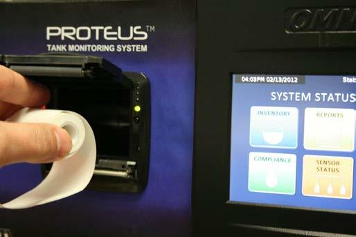
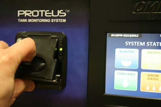
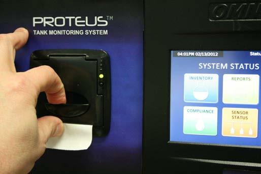
23 3. Thermal Printer Paper Installation Page 23 of 23
1993 Pond Rd., Ronkonkoma, NY Tank Gauging Liquid Level and Leak Detection Systems Relays. OEL8000II Installation Manual PRINT MENU DEL 1 ABC
 OMNTEC Mfg., Inc. 1993 Pond Rd., Ronkonkoma, NY 11779 Tank Gauging Liquid Level and Leak Detection Systems Relays OEL8000II Installation Manual OMNTEC OEL800OII TANK MONITORING SYSTEM OK FAULT ALARM PRINT
ELP21LU3-LF-HLOL THREE CHANNEL
 ELP21LU3-LF-HLOL THREE CHANNEL 516-467-5787 HI LEVEL LOW LEVEL LEAK DETECTION 11.00 TEST SYSTEM DETECTING HORN OFF 6.00 SPECIFICATIONS POWER INPUT 85-125 VAC, 47-440 Hz 16 Watts maximum POWER TO SENSORS
Colibri. Automatic Tank Gauge CL6 Series Installation Guide
 Colibri Automatic Tank Gauge CL6 Series Installation Guide Manual # Revision Date Changes from Previous Revision 000-2153 C Jan. 2013 Pipe compound brand change, Updated Control drawing. Franklin Fueling
Fuel Management System Setup Guide
 Fuel Management System Setup Guide EVO-EXPC & EVO-EXPC2 Expansion Consoles for TS-5000 evo and TS-550 evo Franklin Fueling Systems 3760 Marsh Rd. Madison, WI 53718 USA Tel: +1 608 838 8786 800 225 9787
SAFETY INFORMATION AND WARNINGS
 This manual refers to the Model SST-3 control panel manufactured since October 31, 2013, which uses a universal (100 277 VAC; 50/60 Hz) power supply. Older units use a voltage-specific power supply and
Installation, Operation & Service Manual
 Installation, Operation & Service Manual WARNING Improper installation, adjustment, alteration, service or maintenance can result in death, injury or property damage. Read the Installation, Operation and
Manual No: Revision: E. Groundwater Sensor. Installation Guide
 Manual No: 576013-763 Revision: E Groundwater Sensor Installation Guide Notice Veeder-Root makes no warranty of any kind with regard to this publication, including, but not limited to, the implied warranties
Remote Relay Module (RRM)
") Remote Relay Module (RRM) Instruction Manual WARNING THIS MANUAL MUST BE CAREFULLY READ BY ALL INDIVIDUALS WHO HAVE OR WILL HAVE THE RESPONSIBILITY FOR INSTALLING, USING OR SERVICING THIS PRODUCT. Like
Remote Relay Module (RRM) Instruction Manual WARNING THIS MANUAL MUST BE CAREFULLY READ BY ALL INDIVIDUALS WHO HAVE OR WILL HAVE THE RESPONSIBILITY FOR INSTALLING, USING OR SERVICING THIS PRODUCT. Like
THREE CHANNEL CONTROLLER OMNTEC
 MNTEC Mfg., Inc. 1993 Pond Rd., Ronkonkoma, NY 11779 Tank Gauging Liquid Level and Detection Systems Relays LU3 THREE CHANNEL CNTRLLER MNTEC 631-467-5787 L1 L2 L3 TEST SYSTEM DETECTING HRN FF Phone 631-981-2001
SINGLE CHANNEL CONTROLLER
 MNTEC Mfg., Inc. 1993 Pond Rd., Ronkonkoma, NY 11779 Tank Gauging Liquid Level and Detection Systems Relays LU1 SINGLE CHANNEL CNTRLLER MNTEC 631-467-5787 L1 TEST SYSTEM DETECTING HRN FF Phone (631) 981-2001
NINE CHANNEL CONTROLLER OMNTEC
 MNTEC Mfg., Inc. 1993 Pond Rd., Ronkonkoma, NY 11779 Tank Gauging Liquid Level and Detection Systems Relays LU9 NINE CHANNEL CNTRLLER MNTEC 631-467-5787 L1 L4 L2 L5 L3 SYSTEM DETECTING L7 L6 L8 TEST L9
FMP-ULS UNIVERSAL LIQUID SENSOR INSTALLATION GUIDE
 FMP-ULS UNIVERSAL LIQUID SENSOR INSTALLATION GUIDE The information in this publication is provided for reference only. While every effort has been made to ensure the reliability and accuracy of the information
Manual No: Revision: D. Sump Sensor. Installation Guide
 Manual No: 576013-301 Revision: D Sump Sensor Installation Guide Notice Veeder-Root makes no warranty of any kind with regard to this publication, including, but not limited to, the implied warranties
Manual No: Revision: D. Mag Sump Sensor. Installation Guide
 Manual No: 577013-812 Revision: D Mag Sump Sensor Installation Guide Notice Veeder-Root makes no warranty of any kind with regard to this publication, including, but not limited to, the implied warranties
TLS-300 UST Monitoring and Leak Detection System
 Part 1 General System Requirements 1.1 Description TLS-300 UST Monitoring and Leak Detection System A. These Specifications are intended to provide information by which prospective bidders may understand
Manual No: Revision: H. MicroSensor. Installation Guide
 Manual No: 576013-285 Revision: H MicroSensor Installation Guide Notice Veeder-Root makes no warranty of any kind with regard to this publication, including, but not limited to, the implied warranties
Sentry LIQUID LEVEL CONTROLLER MODEL 120 OPERATING MANUAL.
 Sentry LIQUID LEVEL CONTROLLER MODEL 120 OPERATING MANUAL www.aquaticsentry.com TABLE OF CONTENTS 1. SAFETY PRECAUTIONS... 3 2. APPLICATION... 3 2.1 HIGH AND LOW LEVEL ALARM 2.2 PUMP DOWN CONTROLLER 2.3
Sentry LIQUID LEVEL ALARM MODEL 100 OPERATING MANUAL.
 Sentry LIQUID LEVEL ALARM MODEL 100 OPERATING MANUAL www.aquaticsentry.com TABLE OF CONTENTS 1. SAFETY PRECAUTIONS... 3 2. APPLICATION... 3 2.1 HIGH Liquid Level Alarm 2.2 LOW Liquid Level Alarm 3. INSTALLATION...
Figure 1. Figure 2. See notes 1 and 2 below.
 273 Branchport Avenue Long Branch, N.J. 07740 (800) 631-2148 Thank you for using our products. www.wheelockinc. com INSTALLATION INSTRUCTIONS HORN SPEAKER WITH AMPLIFIER Use this product according to this
Manual No: Revision: J. Groundwater Sensor. Installation Guide
 Manual No: 576013-763 Revision: J Groundwater Sensor Installation Guide Notice Veeder-Root makes no warranty of any kind with regard to this publication, including, but not limited to, the implied warranties
FUSE PANEL Technical Practice N N/L9 10/10 GMT NEBS Level 3 Certified
 0226-03K August 13, 2008 FUSE PANEL Technical Practice N250120-N/L9 10/10 GMT NEBS Level 3 Certified FEATURES 2 isolated groups (busses) of 10 GMT fuses in each (15Amps/GMT position). Polarity insensitive
AUTOMATIC TANK GAUGES
 EVO TM 200 AND EVO TM 400 AUTOMATIC TANK GAUGES INSTALLATION GUIDE The information in this publication is provided for reference only. While every effort has been made to ensure the reliability and accuracy
FMP-HIS AND FMP-HIS-U INSTALLATION GUIDE
 FMP-HIS AND FMP-HIS-U INSTALLATION GUIDE The information in this publication is provided for reference only. While every effort has been made to ensure the reliability and accuracy of the information contained
Single-Point Mini Hydrostatic Sensor for Double-Wall Sumps
 Manual No: 577013-838 Revision: B Single-Point Mini Hydrostatic Sensor for Double-Wall Sumps Installation Guide Notice Veeder-Root makes no warranty of any kind with regard to this publication, including,
INSTRUCTION MANUAL IS-mB1 Minialite Intrinsically Safe Round LED Beacon
 INSTRUCTION MANUAL Minialite Intrinsically Safe Round LED This instruction sheet describes installations which conform to EN60079:Part14:2008 Electrical Installation in Hazardous Areas. When designing
4) Intrinsic Safety Certification
 Intrinsic Safety Certification") INSTRUCTION MANUAL Minialert Intrinsically Safe Round Combined Unit Section Volume Control Tone Generator S2 S3 Tone Selection Switches Fig 1 Simplified block diagram The combined unit is CE marked for
INSTRUCTION MANUAL Minialert Intrinsically Safe Round Combined Unit Section Volume Control Tone Generator S2 S3 Tone Selection Switches Fig 1 Simplified block diagram The combined unit is CE marked for
DB5 Intrinsically Safe Sounder Type DB-5
 Operating Instructions RTK Instruments Limited DB5 Intrinsically Safe Sounder Type DB-5 Description The DB5 Sounder is a strong, lightweight warning sounder, CENELEC certified to Ex II 1G EExia IIC T4
Model Gas Alarm Panel APPLICABILITY & EFFECTIVITY. This manual provides instructions for the following Sierra Monitor products:
 Model 2102 Gas Alarm Panel APPLICABILITY & EFFECTIVITY This manual provides instructions for the following Sierra Monitor products: Model Description 2102-00 Alarm Panel 2 Channel 2102-01 Alarm Panel 2
TS-RA1, TS-RA2 and TS-RK Tank Overfill Alarms
 TS-RA1, TS-RA2 and TS-RK Tank Overfill Alarms Installation Guide franklinfueling.com 3760 Marsh Rd. Madison, WI 53718, USA Tel: +1 608 838 8786 Fax: +1 608 838 6433 Tel: USA & Canada +1 800 225 9787 Tel:
RAM3 Remote Alarm Module
 RAM3 Remote Alarm Module INSTRUCTIONS Installation and Operation of the AMC-RAM3 with AMC Monitors IMPORTANT: Please read this installation and operating instructions completely and carefully before starting.
Pre-March 2016 Design - Click to be redirected to newer SBS-H2 design SBS-H2. Hydrogen Gas Detector Kit
 Pre-March 2016 Design - Click to be redirected to newer SBS-H2 design N56 W16665 Ridgewood Drive Menomonee Falls, WI 53051 SBS-H2 Hydrogen Gas Detector Kit For battery charging rooms and other areas where
Supplement to The PDRP-1001/PDRP-1001A/PDRP-1001E Deluge Preaction Control Panel Manual
 Supplement to The PDRP-1001/PDRP-1001A/PDRP-1001E Deluge Preaction Control Panel Manual Replace the following pages of Document Number 50734 (I56-993-01/D770-19-00), Revision B with the corresponding revised
SET-2000 Oil/Sludge. Alarm Device for Oil Separators. Installation and Operating Instructions
 SET-000 Oil/Sludge Alarm Device for Oil Separators Copyright 007 Labkotec Oy We reserve the right for changes without notice TABLE OF CONTENTS GENERAL... INSTALLATION... 4. SET-000 Oil/Sludge Control Unit...
INSTALLATION, OPERATION AND MAINTENANCE
 INLINE HEATER INSTALLATION, OPERATION AND MAINTENANCE MODELS: ILS SERIES 1.5kW 120V SINGLE PHASE BEFORE YOU BEGIN CHECK ALL ELECTRICAL CONNECTIONS TO ALL COMPONENTS WITHIN THE HEATER FOR TIGHTNESS. CONNECTIONS
Interstitial Liquid Sensor - Fiberglass Tanks
 Manual No: 576013-617 Revision: J Interstitial Liquid Sensor - Fiberglass Tanks Installation Guide Notice Veeder-Root makes no warranty of any kind with regard to this publication, including, but not limited
SLATE. Rectification Ampli-Check Flame Amplifier INSTALLATION INSTRUCTIONS R8001V1031
 SLATE Rectification Ampli-Check Flame Amplifier R8001V1031 INSTALLATION INSTRUCTIONS Scan for more information Application SLATE brings configurable safety and programmable logic together into one single
CLIMAGUARD Air-to-Air Outdoor Heat Exchangers INSTRUCTION MANUAL. Rev. H 2015 Pentair Equipment Protection P/N
 CLIMAGUARD Air-to-Air Outdoor Heat Exchangers TX23, TX33, TX38, TX52 Model INSTRUCTION MANUAL Rev. H 2015 Pentair Equipment Protection P/N 10-1008-221 87976519 TABLE OF CONTENTS RECEIVING THE HEAT EXCHANGER...3
DESCRIPTIVE AND INSTALLATION INSTRUCTION MANUAL FOR MODEL G1000 AND H1000 SERIES ANNUNCIATORS
 DESCRIPTIVE AND INSTALLATION INSTRUCTION MANUAL FOR MODEL G1000 AND H1000 SERIES ANNUNCIATORS SEEKIRK, INC. 2420 Scioto Harper Dr. Columbus, OH 43204 Tel: (614) 278-9200 FAX: (614) 278-9257 email: seekirk@seekirk.com
Noran Tel. FUSE PANEL Technical Practice N NCY 2/2 KLM and 4/4 GMT NEBS Level 3 Certified
 0232-03J December 13, 2006 FUSE PANEL Technical Practice N215112-NCY 2/2 KLM and 4/4 GMT NEBS Level 3 Certified FEATURES 2 isolated groups (busses) of 2 KLM and 4 GMT fuses in each (30Amps/KLM, 15Amps/GMT).
Operating & Maintenance Manual. Alert-4 Ethernet LCD Master Alarm
 Operating & Maintenance Manual Alert-4 Ethernet LCD Master Alarm w w w. a m i c o. c o m Contents User Responsibility 4 Introduction 4 Features 5 Description of the Alarm 5 Shipment Details 5 The Alarm
DESCRIPTIVE AND INSTALLATION INSTRUCTION MANUAL FOR MODEL AH1000, BH1000, AND EH1000 SERIES ANNUNCIATORS
 DESCRIPTIVE AND INSTALLATION INSTRUCTION MANUAL FOR MODEL AH1000, BH1000, AND EH1000 SERIES ANNUNCIATORS SEEKIRK, INC. 2420 Scioto Harper Dr. Columbus, OH 43204 Tel: (614) 278-9200 FAX: (614) 278-9257
BID-SPEC_INTEGRA_100 Rev. 0. Bid Specifications and General Description OPW SiteSentinel Integra 100 Automatic Tank Monitoring System
 BID-SPEC_INTEGRA_100 Rev. 0 Bid Specifications and General Description OPW SiteSentinel Integra 100 Automatic Tank Monitoring System Part 1. General Overview 1.1 Summary This document describes the minimum
Operating Manual. Gasgard 100 Control System. Order No.: /00. MSAsafety.com
 Operating Manual Gasgard 100 Control System Order No.: 10153908/00 MSAsafety.com Warning! THIS MANUAL MT BE CAREFULLY READ BY ALL INDIVIDUALS WHO HAVE OR WILL HAVE THE RESPONSIBILITY FOR ING OR SERVICING
SET-2000 Hi Level/Oil
 Labkotec Oy Labkotie 1 FI-36240 KANGASALA FINLAND Tel: + 358 29 006 260 Fax: + 358 29 006 1260 13.03.2008 Internet: www.labkotec.fi Alarm Device for Oil Separators Copyright 2008 Labkotec Oy We reserve
FUSE PANEL. Technical Practice N N/L33 10/10 GMT Front Access NEBS Level 3 Certified
 0220-03J Oct 9, 2006 Noran Tel FUSE PANEL Technical Practice N25020-N/L33 0/0 GMT Front Access NEBS Level 3 Certified FEATURES 2 isolated groups (busses) of 0 GMT fuses in each (5Amps/GMT position). Polarity
3800 North Mill Road Vineland, NJ USA Tel: Fax: Web: Rev. A
 Versa-Roll Roller Apparatus - Modular CLS-3857 OPERATIONS MANUAL 3800 North Mill Road Vineland, NJ 08360 USA Tel: 1-800-843-1794 Fax: 1-800-922-4361 Web: www.cglifesciences.com Rev. A Contents: General
SLATE. UV Ampli-Check Flame Amplifier INSTALLATION INSTRUCTIONS R8001S1071
 SLATE UV Ampli-Check Flame Amplifier R8001S1071 INSTALLATION INSTRUCTIONS Scan for more information Application SLATE brings configurable safety and programmable logic together into one single platform.
Environmental Monitoring SmartSlot Card
 Environmental Monitoring SmartSlot Card AP9612TH Installation and Quick Start Manual Contents Introduction............................. 1 Overview 1 Product inventory 1 Safety notice 2 Your inspection
ELECTRIC FIREPLACE HEATER WITH SINGLE GLASS DOOR
 ELECTRIC FIREPLACE HEATER WITH SINGLE GLASS DOOR Model 91797 ASSEMBLY and Operating Instructions Visit our website at: http://www.harborfreight.com Read this material before using this product. Failure
10810 W. LITTLE YORK RD. #130 HOUSTON, TX VOICE (713) FAX (713) web: IMPORTANT!!!!
 FAX (713) web: IMPORTANT!!!!") 10810 W. LITTLE YORK RD. #130 HOUSTON, TX 77041-4051 VOICE (713) 973-6905 FAX (713) 973-9352 web: www.twrlighting.com IMPORTANT!!!! PLEASE TAKE THE TIME TO FILL OUT THE FORM COMPLETELY. FILE IN A SAFE
10810 W. LITTLE YORK RD. #130 HOUSTON, TX 77041-4051 VOICE (713) 973-6905 FAX (713) 973-9352 web: www.twrlighting.com IMPORTANT!!!! PLEASE TAKE THE TIME TO FILL OUT THE FORM COMPLETELY. FILE IN A SAFE
MAINS KLARGESTER SEPARATOR ALARM INSTALLATION & OPERATIONS MANUAL
 MAINS KLARGESTER SEPARATOR ALARM INSTALLATION & OPERATIONS MANUAL Contents IMPORTANT... 3 General Description... 4 General Operation... 4 Changing Factory Settings... 4 Alarm Type... 4 Check Interval...
Instruction Manual. Alarm Unit For Low Gas Level # Read manual before use! Observe all safety information! Keep manual for future use!
 Mess-, Regel- und Überwachungsgeräte für Haustechnik, Industrie und Umweltschutz Lindenstraße 20 74363 Güglingen Telefon +49 7135-102-0 Service +49 7135-102-211 Telefax +49 7135-102-147 info@afriso.de
WATLOW ELECTRIC MFG CO. FIREBAR Screw Plug Installation & Maintenance Manual I&M NUMBER: Page: 1 Date: 11/25/2013 Rev: 4.
 I&M NUMBER: 316-42-3-1 Page: 1 Pre Installation Check to make sure that heater received is the same as that ordered. Elements may come in contact with each other during shipment. Minor adjustments to elements
Manual No: Revision: C. Overfill Alarm. Installation Guide
 Manual No: 576013-589 Revision: C Overfill Alarm Installation Guide Notice Veeder-Root makes no warranty of any kind with regard to this publication, including, but not limited to, the implied warranties
SF180 Installation Instructions
 SF180 Installation Instructions 1 Fan Installation & Operating Instructions Please Read and Save These Instructions. DO NOT CONNECT POWER SUPPLY UNTIL FAN IS COMPLETELY INSTALLED. MAKE SURE ELECTRICAL
14300 MAINS SEPARATOR ALARM MANUAL
 Conder Environmental Solutions 14300 MAINS SEPARATOR ALARM MANUAL Separator and Alarm provided by: Alarm Installation, Commissioning & Servicing Support Please contact: www.envirotank.com.au www.envirotank.co.nz
Powerohm Resistors Digital HRG System
 Installation and Operating Instructions Powerohm Resistors Digital HRG System This manual provides general information, installation, operation, maintenance, and system setup information for the Powerohm
Installation Instructions
 50ZPB, C, 50ZHB, C, PA3Z ---A, PH3Z ---A, PA4Z, PH4Z, PAJ4,PHJ4,WJA4,WJH4 SMALL PACKAGED PRODUCTS (SPP) Accessory Electric Heaters 5---20 kw For 14 SEER, R---410A Manufactured Home Installation Instructions
Explosion Proof Line Powered Telephone Ringer
 Explosion Proof Line Powered Telephone Ringer P7020 CE20 Without Projection Horn P7021 CE20 With Projection Horn P004572 Rev. E 180416 4/16/2018 12:32 PM Ph: 403.258.3100 \ email:info@guardiantelecom.com
SET-2000 Oil/Sludge 12 VDC
 Labkotec Oy Myllyhaantie 6 FI-33960 PIRKKALA FINLAND Tel: + 358 29 006 260 Fax: + 358 29 006 1260 12.2.2015 Internet: www.labkotec.fi 1/14 SET-2000 Oil/Sludge 12 VDC Alarm Device for Oil Separators with
WATLOW IND. WATROD Circulation Heater Installation & Maintenance Manual I&M NUMBER: Page: 1 Date: 6/11/2008 Rev: 2.00
 I&M NUMBER: 316-42-5-1 Page: 1 Pre Installation Check to make sure that heater received is the same as that ordered. Watlow heaters are built to comply with UL and CSA dielectric requirements, it may be
SLATE. Base Module INSTALLATION INSTRUCTIONS R8001A1001
 SLATE Base Module R8001A1001 INSTALLATION INSTRUCTIONS Scan for more information Application SLATE brings configurable safety and programmable logic together into one single platform. The platform can
D SYSTEM CONTROL DWG. APPROVED BY. OrCAD 6 ROSEMOUNT 2410
 FIELDBUS INTRINSICALLY SAFE CONCEPT (FISCO) APPROVAL FISCO allows interconnection of intrinsically safe apparatus to associated apparatus not specially examined in such combination. The criteria for interconnection
Air Pump Up to 800 gallons
 Air Pump Up to 800 gallons REMINDER CALL 1-888-755-6750 BEFORE RETURNING TO STORE. PACKAGE CONTENTS ITEM #PBPAPK40W Questions, problems, missing parts? Before returning to your retailer, call our customer
21-light Remote Annunciator. Owner s Manual
 21-light Remote Annunciator Owner s Manual Annunciator Description... Inside Font Cover Detailed Specifications... 1 Environmental Specifications... 1 Power Supply Requirements... 1 Communication With
ACCURATE ELECTRONICS INC
 ACCURATE ELECTRONICS INC Page 1 of 7 Model 108078 2 Sept 09 WWW.ACCURATE.ORG PO BOX 1654 97075-1654 8687 SW Hall Blvd 97008 BEAVERTON OR USA 503.641.0118 FAX 503.646.3903 Practice Section 108078 Rev A
GAS MONITOR Model Model
 Sierra Monitor Corporation 1991 Tarob Court, Milpitas, CA 95035 (408) 262-6611 (800) 727-4377 (408) 262-9042 - Fax E-mail: sierra@sierramonitor.com Web Site: www.sierramonitor.com GAS MONITOR Model 2350-00
Controllers. Instruction Manual WARNING
 Controllers Instruction Manual WARNING THIS MANUAL MUST BE CAREFULLY READ BY ALL INDIVIDUALS WHO HAVE OR WILL HAVE THE RESPONSIBILITY FOR INSTALLING, USING OR SERVICING THIS PRODUCT. Like any piece of
10810 W. LITTLE YORK RD. #130 HOUSTON, TX VOICE (713) FAX (713) web: IMPORTANT!!!!
 FAX (713) web: IMPORTANT!!!!") 10810 W. LITTLE YORK RD. #130 HOUSTON, TX 77041-4051 VOICE (713) 973-6905 FAX (713) 973-9352 web: www.twrlighting.com IMPORTANT!!!! PLEASE TAKE THE TIME TO FILL OUT THE FORM COMPLETELY. FILE IN A SAFE
10810 W. LITTLE YORK RD. #130 HOUSTON, TX 77041-4051 VOICE (713) 973-6905 FAX (713) 973-9352 web: www.twrlighting.com IMPORTANT!!!! PLEASE TAKE THE TIME TO FILL OUT THE FORM COMPLETELY. FILE IN A SAFE
Use this product according to this instruction manual. Please keep this instruction manual for future reference. MODELS: ST-H15-B & ST-H30
 273 Branchport Avenue Long Branch, N.J. 07740 (800) 631-2148 Thank you for using our products. www.wheelockinc. com INSTALLATION INSTRUCTIONS HORN SPEAKER WITH MULTI-TAP TRANSFORMER Use this product according
WATLOW IND. WATROD Flange Heater Installation & Maintenance Manual I&M NUMBER: Page: 1 Date:6/11/2008 Rev: 2.00
 I&M NUMBER: 316-42-8-1 Page: 1 _ Pre Installation Check to make sure that heater received is the same as that ordered. Elements may come in contact with each other during shipment. Minor adjustments to
ACCURATE ELECTRONICS INC PO BOX SW HALL BLVD BEAVERTON OR USA FAX
 Page 1 of 10 Model 10807800 January 2014 ACCURATE ELECTRONICS INC PO BOX 1654 97075-1654 8687 SW HALL BLVD 97008 BEAVERTON OR USA 503.641.0118 FAX 503.646.3903 WWW.ACCURATE.ORG Practice Section 10807800
Instruction Manual WARNING
 Controllers Instruction Manual WARNING THIS MANAUL MUST BE CAREFULLY READ BY ALL INDIVIDUALS WHO HAVE OR WILL HAVE THE RESPONSIBILITY FOR INSTALLING, USING OR SERVICING THIS PRODUCT. Like any piece of
Single Phase Simplex SXL21=3, SXL24=3, SXH21=3, and SXH24=3
 Single Phase Simplex SXL21=3, SXL24=3, SXH21=3, and SXH24=3 Manufactured by SJE-Rhombus Installation Instructions and Operation/Troubleshooting Manual 7000 Apple Tree Avenue Bergen, New York 14416 Phone:
INSTALLATION INSTRUCTIONS MODEL PA-250 AND PA-500 BOOSTER AMPLIFIER
 273 Branchport Avenue Long Branch, N.J. 07740 (908) 222-6880 INSTALLATION INSTRUCTIONS MODEL PA-250 AND PA-500 BOOSTER AMPLIFIER GENERAL: The Series PA-250 and PA-500 Watt Booster Amplifiers are designed
HI Industrial Utility Heater HI Soleus Air International
 HI1-50-03 Industrial Utility Heater HI1-50-03 2010 Soleus Air International Thank you for choosing a Soleus Air Utility Heater. This owner s manual will provide you with valuable information necessary
Smart Series TAS-05-11, TAS-05-12
 Smart Series TAS-05-, TAS-05-2 Temperature Alarm & System Control Module User s Manual D-M-E Company ED-0063-OT-002-A D-M-E TAS User s Manual Page Copyright D-M-E Company 2000. All rights reserved. D-M-E
OilSET Installation and Operating Instructions. Oil Separator Alarm Device with SET/DM3AL sensor
 Labkotec UK Ltd Adminicle House 1 Lumb Lane Audenshaw Manchester M34 5WH GREAT BRITAIN Tel: 0844 3350 477 Fax: 0161 4281 179 E-mail: info@labkotec.co.uk 10.8.2012 Internet: www.labkotec.co.uk 1/13 OilSET-1000
* These Remote Mics must be SPRM-GP
 273 Branchport Avenue Long Branch, NJ 07740 (800) 6312148 Thank you for using our products. www.coopernotification.com INSTALLATION INSTRUCTIONS REMOTE MICROPHONE EXPANSION MODULE Use this product according
FUSE PANEL. Technical Practice N N/0803 5/5 GMT Front Access NEBS Level 3 Certified
 0803-03B April 17, 2008 Noran Tel PANEL Technical Practice N250110-N/0803 5/5 GMT Front Access NEBS Level 3 Certified FEATURES 2 isolated groups (busses) of 5 GMT fuses in each (15Amps/GMT position). Polarity
WATLOW IND. FIREBAR Flange Heater Installation & Maintenance Manual I&M NUMBER: Page: 1 Date: 6/11/2008 Rev: 2.00
 I&M NUMBER: 316-42-2-1 Page: 1 Pre Installation Check to make sure that heater received is the same as that ordered. Elements may come in contact with each other during shipment. Minor adjustments to elements
MODEL ZAC ZONE ANNUNCIATOR/CONTROLLER DESIGNED FOR ZONE ANNUNCIATION AND MONITORING
 MODEL ZAC-32 32 ZONE ANNUNCIATOR/CONTROLLER DESIGNED FOR ZONE ANNUNCIATION AND MONITORING 32 HARD WIRED ZONES CAN BE NORMALLY-OPEN OR NORMALLY-CLOSED ZONE WIRING RUNS CAN BE AS FAR AS 10,000 FEET FROM
Tank Gauging System Special Safety Instruction
 Tank Gauging System www.rosemount-tg.com Rosemount TankRadar REX Table of Contents Contents SPECIAL SAFETY INSTRUCTION........................ 1-1 1. GENERAL REQUIREMENTS....................... 1-2 1.1
INSTRUCTION MANUAL. Revised: July 2, 2017 DRAWING NO REV. A LC1000 SERIES INTRINSICALLY SAFE ALARM CONSOLE
 PNEUMERCATOR Liquid Level Control Systems AUDIBLE ALARM CONTROLS INSTRUCTION MANUAL Revised: July 2, 2017 DRAWING NO. 20000 REV. A LC1000 SERIES INTRINSICALLY SAFE ALARM CONSOLE COPYRIGHT 2017 PNEUMERCATOR
TECHNICAL ASSISTANCE TOLL FREE TELEPHONE NUMBER TECHNICAL ASSISTANCE FAX:
 ACORN SAFETY P.O. BOX 3527 CITY OF INDUSTRY, CA 91744-0527 UNITED STATES OF AMERICA WWW.ACORNSAFETY.COM INSTALLATION, OPERATION AND MAINTENANCE INSTRUCTIONS ELECTRIC ALARM WITH LIGHT AND HORN Models S0000-AL1
2 To 1 Sensor Input Box
 Manual No: 577013-869 Revision: D 2 To 1 Sensor Input Box Installation Guide Notice Veeder-Root makes no warranty of any kind with regard to this publication, including, but not limited to, the implied
DETCON MODEL AV1/AV2-C1D2M Hazardous Duty Class I. Div 2, Multitone Alarm Station
 DETCON MODEL AV1/AV2-C1D2M Hazardous Duty Class I. Div 2, Multitone Alarm Station Operator s Installation and Instruction Manual DETCON, Inc. 3200 Research Forest Dr, The Woodlands, Texas 77387 Ph.281.367.4100
SPECIFICATION: AlarmLine TM INTELLIGENT LINEAR HEAT DETECTION
 1. GENERAL SPECIFICATION 1.1 The contractor shall provide an Intelligent AlarmLine Linear Heat Detection System to perform the following functionality: A. Fire Alarm, Supervisory and Trouble-Event Initiation
FMP-DDS & FMP-DTS. Discriminating Dispenser Sump & Turbine Sump BriteSensor. Installation Instructions
 & Discriminating Dispenser Sump & Turbine Sump Brite Installation Instructions Franklin Fueling Systems 3760 Marsh Rd. Madison, WI 53718 USA Tel: +1 608 838 8786 800 225 9787 Fax: +1 608 838 6433 www.franklinfueling.com
INSTRUCTION MANUAL. SIL 3 - SIL 2 IIB Group Power Supply for Hazardous Area Equipment DIN-Rail Model PSD1001C PSD1001C
 PSD1001C INSTRUCTION MANUAL SIL 3 SIL 2 IIB Group Power Supply for Hazardous Area Equipment DINRail Model PSD1001C PSD1001C SIL 3 SIL 2 IIB Group Power Supply for hazardous Area Equipment ISM006510 General
Quick Start Guide For the
 A Leader in Level Measurement Quick Start Guide For the Universal IV Lite and Universal IV Pro Model Transmitters 2-Wire RF Admittance / Capacitance Level Measurement System with HART Protocol For Assistance
! The Caution Symbol (exclamation point) alerts you to a "CAUTION", a safety or
 alerts you to a CAUTION, a safety or") I&M NUMBER: 316-42-10-1 Page: 1 Pre Installation Check to make sure that heater received is the same as that ordered. Elements may come in contact with each other during shipment. Minor adjustments to
I&M NUMBER: 316-42-10-1 Page: 1 Pre Installation Check to make sure that heater received is the same as that ordered. Elements may come in contact with each other during shipment. Minor adjustments to
Vanguard. Toxic & combustible gas detector
 Toxic & combustible gas detector T C D 5 0 - B - 0 1 Capability Overview Wireless Capability WirelessHART communication 7.2 IEC 62591 compatible Integrated HART terminals Adjustable update rate Quick Mount
FAILURE TO FOLLOW THESE INSTRUCTIONS CAN CAUSE FIRE, EXPLOSION, ELECTRICAL SHOCK, PROPERTY DAMAGE, PERSONAL INJURY OR DEATH.
 HKR ELECTRIC HEAT KIT INSTALLATION INSTRUCTIONS AT TENTION INST NSTALLING PERS ERSONNEL As a professional installer, you have an obligation to know the product better than the customer. This includes all
SET Installation and Operating Instructions. Level switch for one sensor
 Labkotec Oy Myllyhaantie 6 FI-33960 PIRKKALA FINLAND Tel.: +358 29 006 260 Fax: +358 29 006 1260 7.11.2013 Internet: www.labkotec.fi 1/14 SET-1000 Level switch for one sensor Copyright 2013 Labkotec Oy
FMP-MWS. (Discriminating Monitoring Well Sensor BriteSensor ) Installation Instructions
 Installation Instructions") FMP-MWS (Discriminating Monitoring Well Sensor BriteSensor ) Installation Instructions Franklin Fueling Systems 3760 Marsh Rd. Madison, WI 53718 USA Tel: +1 608 838 8786 800 225 9787 Fax: +1 608 838 6433
FMP-MWS (Discriminating Monitoring Well Sensor BriteSensor ) Installation Instructions Franklin Fueling Systems 3760 Marsh Rd. Madison, WI 53718 USA Tel: +1 608 838 8786 800 225 9787 Fax: +1 608 838 6433
Model AV1LED Audio-Visual LED Light Installation and Maintenance Manual
 Model AV1LED Audio-Visual LED Light Installation and Maintenance Manual 2561528A REV. A 810 Printed in U.S.A. Warranty Seller warrants all goods for five years on parts and 2-1/2 years on labor, under
Users Manual. LAURUS Systems, Inc. - Ph: Fax:
 Users Manual LAURUS Systems, Inc. - Ph: 410-465-5558 - Fax: 410-465-5257 - www.laurussystems.com Introduction The rad-d is a security and inspection system that detects emissions from radioactive material.
Intrinsically Safe, NEMA 4, Type 4X, IP67 Loop-Powered Meter
 PD685 Intrinsically Safe, NEMA 4, Type 4X, IP67 Loop-Powered Meter Actual Size Digits C US Intrinsically Safe 3½ Digits LARGE DISPLAY NEMA 4, Type 4X, IP67 Loop-Powered Field-Mount Process Meter 4-20 ma
Surge Protective Devices Installation, Operation and Maintenance Manual. LowProfile Series: 080 and 120
 LowProfile Series: 080 and 120 Surge Protective Devices Installation, Operation and Maintenance Manual P.O. Box 3760 Winter Park, FL 32790 USA 1.800.647.1911 www.tpssurge.com LOWPROFILE InstaLLatIOn, OPERatIOn