Personal Single Gas Monitor. Activation Operation Troubleshooting
|
|
|
- Gwenda Craig
- 5 years ago
- Views:
Transcription


1 Personal Single Gas Monitor Activation Operation Troubleshooting Part Number: Revision: 3.0 Release Date: January 1, 2009
2 Table of Contents Warnings and Cautionary Statements... 3 Hardware Overview... 5 Unpacking the Instrument... 5 Display Overview... 6 Activation... 7 Countdown Screen... 7 Operating Quick Start Guides... 8 Basic Operating Flowchart... 8 General Operation Gas Monitoring Screen Days Since Calibration Days Until Calibration Zero Initiate (Toxic Sensors Only For Oxygen Sensors, Skip to Calibration Section) Zeroing Failed Zero Passed Calibration Calibration Passed Calibration Failed Bump Test.20 Peak Reading TWA Gas Reading Screen STEL Gas Reading Screen Create Session Event Log Shutdown Shutdown Password Screen Configuration Mode Introduction Security Code Calibration Days Since Calibration Days Until Calibration Initiate Print Low Alarm Setpoint High Alarm Setpoint TWA Alarm Setpoint Set TWA Interval STEL Alarm Setpoint Set Calibration Gas Concentration Set Clock Set Calendar Month/Day Set Security Code Set Data Log Interval Primary Display Setting Always On Option INDUSTRIAL SCIENTIFIC Revision 3.0 (p/n: )
3 Set Confidence Indicator Alarm Latch Setup Zero In Field Option Cal In Field Option Cal Date View Option Screen Calibration Past Due Alarm Calibration Due Setpoint Bump in Field Option Bump Overdue Alarm Enable Bump Test Interval Bump Test Timeout The DS2 Docking Station (Optional Accessory) Datalink (Optional Accessory) Troubleshooting and Maintenance Diagnosing Common Problems Alarm Screen Battery Failure Sensor Missing Error Unexpected Instrument Error Replacing Parts Replacing the Sensor Sensor Specifications Ordering Information Accessories and Peripheral Equipment General Specifications Lifetime Warranty Policy Limitation of Liability Agency Certifications Warnings and Cautionary Statements IMPORTANT: Failure to perform certain procedures or note certain conditions may impair the performance of this product. For maximum safety and optimal performance, please read and follow the procedures and conditions listed below. IMPORTANT: Read and understand this manual before operating. WARNING: Substitution of components may impair intrinsic safety. WARNING: The instrument contains a lithium battery which may leak or explode if the instrument is mistreated. Do not attempt to disassemble or dispose of in fire. For Europe Only: The GasBadge Pro has been certified to meet the following standards on a calibration interval of 30 days or less: 1) EN for CO performance over the range of PPM and for H 2 S performance over the range of PPM; and, 2) EN for O 2 performance in deficiency and enrichment applications. WARNING: To prevent ignition of flammable or combustible atmospheres, only change the battery in a non-hazardous location. Revision 3.0 (p/n: ) INDUSTRIAL SCIENTIFIC 3
4 WARNING: To prevent ignition of flammable or combustible atmospheres, read, understand, and adhere to the manufacturer s maintenance procedures. WARNING: To prevent ignition of flammable or combustible atmospheres, only the following lithium CR2 batteries are approved for use with this instrument. Manufacturer Panasonic Sanyo Duracell Ultra Kodak Energizer e 2 Varta/Power One Part Number CR2 CR2 CR2/DLCR2 CR2/KCR2 1CR2/EL1CR2/CR2 CR2/CR2NP The GasBadge Pro is certified for use within the ambient temperature range of -40 o C to 60 o C (-40 o F to 140 o F). The GasBadge Pro complies with the relevant provisions of European ATEX Directive 94/9/EC and EMC Directive 89/336/EEC, amended by Directives 92/31/EEC, 92/31/EEC and 93/68/EEC. The EC Type Examination Certificate is DEMKO 05 ATEX with marking Code EEx ia I/IIC T4, for Equipment Group and Category I M2 and II 1G. The GasBadge Pro devices (P/N: ) are constructed with reference to published standards of Directive 72/23/EEC, to eliminate electrical risks and fulfill of Annex II of Directive 94/9/EC. The GasBadge Pro is marked with the symbol Exia, which is used by the Canadian Standards Association to designate the instrument as INTRINSICALLY SAFE. Note that the intrinsic safety is not certified by CSA when this instrument is used in atmospheres containing oxygen concentrations above 21%. Prior to each day s use, a bump test should be performed. If the instrument does not pass the bump test, a full calibration is recommended. For purposes of minimizing electromagnetic interference (EMI) and radio-frequency interference (RFI) in the application environment, the alarm functions of the GasBadge Pro are unaffected when placed in close proximity to handheld radios 1. This applies to all sensors specified for this instrument. Never cover or insert foreign objects into the alarm signal opening. The opening must remain clear and free of foreign objects, otherwise any alerts made during an alarm state may not be heard or identified. Contact your service representative immediately if you suspect that the GasBadge Pro is working abnormally. 1 Within 1 meter of a handheld radio emitting an electromagnetic signal of up to 5 watts in the frequency range of 80 MHz to 2.4 GHz. 4 INDUSTRIAL SCIENTIFIC Revision 3.0 (p/n: )

5 Hardware Overview Concussion-proof Overmold Sensor Opening and Removable Patch (Water/Dust Barrier) Graphical Display Visual Alarm Lens Mode Button (On/Off Button) Enter button Audible Alarm Port Up Arrow Button Button IR Port Unpacking the Instrument The shipping box should contain the following items. Account for each item before discarding the box. Quantity Part Number Description x GasBadge Pro Monitor Belt Clip Manual Cal-Cup Urethane Tubing After unpacking, if any listed item is missing, contact either your local distributor of Industrial Scientific products or call Industrial Scientific Corporation at DETECTS ( ) in the United States and Canada, or Revision 3.0 (p/n: ) INDUSTRIAL SCIENTIFIC 5


6 Display Overview LCD Display Panel Overview 6 INDUSTRIAL SCIENTIFIC Revision 3.0 (p/n: )


7 Activation To turn on the GasBadge Pro, hold the Mode button for at least 3 seconds. Each alarm indicator the left LED, the right LED, the speaker, the vibrating alarm, and the backlight is tested for one second. Following the segment and alarm indicator test, the instrument displays the software version. If the Days Since/Until Calibration option is enabled, this screen is displayed. Activating the GasBadge Pro Personal Monitor NOTE: Any button activates the backlight for a period of 5 seconds. Countdown Screen The countdown screen is entered after the Software Version screen times out. The primary display shows a decrementing countdown from 20 seconds. To enter the Configuration Mode, the up and down arrow buttons simultaneously for 3 seconds during this countdown. The device will display the Enter Security Code screen (assuming the security code has been Countdown Screen set to a number greater than zero). If the security code is set to zero, then the Security Code screen is bypassed and the Zero Initiate screen (for toxic sensors) or Cal Initiate screen (for O 2 sensors) is displayed. If no buttons are ed, the GasBadge Pro proceeds to the Gas Monitoring screen after the countdown reaches zero. The confidence Checkmark indicator is active at this point, indicating that all internal checks have passed. Revision 3.0 (p/n: ) INDUSTRIAL SCIENTIFIC 7
8 Operating Quick Start Guides Basic Operating Flowchart Gas Monitoring Screen Initiate New Datalogging Session Days Since/Until Calibration Due (if Enabled) Short Term Exposure Limit Reading (STEL) Zero Initate (if Enabled) Time Weighted Average Reading (TWA) Bump Test Initiate (if Enabled) Peak Reading 8 INDUSTRIAL SCIENTIFIC Revision 3.0 (p/n: )
9 Configuration Mode Flowchart GasBadge Pro Personal Single Gas Monitor Warm-up Countdown TWA Time Base Setting Hold 3-Sec. Enter Security Code if not = 0 STEL Alarm Setting Initiate Zero/Calibration Cal Gas Value Setting Days Since/Until Calibration Set Clock Initiate IR Data Print Set Calendar Low Alarm Setting Security Code Setting High Alarm Setting Recording Interval Setting TWA Alarm Setting A Display Setting Revision 3.0 (p/n: ) INDUSTRIAL SCIENTIFIC 9
10 Configuration Mode Flowchart (Continued) A Always On Enable Calibration Due Alarm Enable Confidence Beep Enable Calibration Interval Setting Alarm Latch Enable Field Bump Test Enable Field Zero Enable Bump Test Due Alarm Enable Field Calibration Enable Bump Test Interval Days Since/Until Calibration Setting Bump Test Time-Out 10 INDUSTRIAL SCIENTIFIC Revision 3.0 (p/n: )
 Calibration (if enabled) Peak Reading Time Weighted Average (TWA) Reading (except O 2 ) Short Term Exposure Limit (STEL)")

 Gas Sensor Type Only (selectable for either sensor type).")
11 General Operation Normal operation modes include the following: Gas Monitoring Days Since/Until Calibration (if enabled) Zero Initiate (if enabled) Calibration (if enabled) Peak Reading Time Weighted Average (TWA) Reading (except O 2 ) Short Term Exposure Limit (STEL) Reading (except O 2 ) Create Session. The operation modes are explained in the sections that follow. Gas Monitoring Screen The primary operating screen is the Gas Monitoring screen. The Gas Monitoring screen may utilize one of three displays: Concentration in PPM (for toxic sensors) Concentration in Percent Volume (for oxygen sensors) Gas Sensor Type Only (selectable for either sensor type). Gas Monitoring Screens NOTE: The Enter button activates the backlight and initiates IR print. Revision 3.0 (p/n: ) INDUSTRIAL SCIENTIFIC 11
12 In the presence of a gas concentration that exceeds the low or high level threshold, the instrument enters an alarm screen. Alarm detection in any of the instrument s normal operating screens the battery life, peak, or initiate print screens forces a transition back to the Gas Monitoring screen. The alarm screen is indicated on the display by the Alarm indicator and either the Up indicator or Down indicator which designate a high or low alarm, respectively. High Alarm Screen These icons are in addition to the values and icons normally displayed in the current monitoring screen. From this screen, the can toggle through the menus. s Available from Monitor Screen Enter button Up Arrow button Clear any latched alarms if latch alarms feature is enabled and initiate the printing of the event log. If View Cal Date is set, go to Days Since/Until Calibration screen. If View Cal Date is not set, go to: (a) Zero Initiate screen (if Zero In Field is enabled), or (b) Peak Gas Reading screen (if Zero In Field is disabled). NOTE: The battery indicator is active and indicates the battery life remaining. NOTE: In an over-range condition, the display shows a blinking OR. Any over-range values in the event log or peaks are truncated at the measurement range of the sensor. The instrument stores the number of over-range conditions that occur. This number is accessible through the ModBus interface. 12 INDUSTRIAL SCIENTIFIC Revision 3.0 (p/n: )

13 Days Since Calibration GasBadge Pro Personal Single Gas Monitor The primary display of the Days Since Calibration screen indicates the number of days that have passed since the last calibration. The Days indicator displays the number as days, and the Gas Bottle indicator shows that this is a calibration issue. This screen is displayed if the View Cal Date option is turned on, and the View Last/Next Cal Date option is set to view the last cal date. Days Since Calibration Screen s Available from the Days Since Calibration Screen Up Arrow button 30 second timeout If View Cal Date is set, go to Days Since/Until Calibration screen. If View Cal Date is not set, go to: (c) Zero Initiate screen (if Zero In Field is enabled), or (d) Peak Gas Reading screen (if Zero In Field is disabled). Go to Gas Monitoring screen. Revision 3.0 (p/n: ) INDUSTRIAL SCIENTIFIC 13
14 Days Until Calibration The primary display of the Days Until Calibration screen indicates the number of days until the next calibration is due. The Days indicator is active to designate this number as days, and the Gas Bottle indicator is active to designate it as a calibration issue. This screen is displayed if the View Cal Date option is turned on, and the View Last/Next Cal Date option is set to view the next cal date. Figure 1- Days Since Calibration s Available from the Days Until Calibration Screen Up Arrow button 30 second timeout If Zero In Field is enabled, go to Zero Initiate screen (for toxic sensor) or Cal Initiate (for O 2 sensor). If Zero In Field is disabled, go to Peak Gas Reading screen. Go to Gas Monitoring screen. 14 INDUSTRIAL SCIENTIFIC Revision 3.0 (p/n: )
, by ing the Enter button.")
15 Zero Initiate (Toxic Sensors Only For Oxygen Sensors, Skip to Calibration Section) IMPORTANT: Before zeroing, ensure the instrument is located in a fresh air environment. If background gas is present, the use of a zero air cylinder is recommended. The Zero screen allows you to begin the zeroing process (for toxic sensors), by ing the Enter button. The Zero icon blinks, signifying that zeroing will begin if you Enter. For oxygen sensors, this screen is not displayed. Pressing the at this screen navigates to the Peak screen. While zeroing, the display shows the Zero icon, the gas type, and a blinking Clock icon to show that this step takes some time. If the zeroing process fails, a transition is made to the Zero Fail screen. If the zeroing passes, a transition is made to the Zero Pass screen. Zero Initiate Screen Zeroing In Process Zeroing Failed The Zeroing Failed screen (with the Zero icon and a flashing Warning icon) indicates to the user that the zeroing process could not achieve a sensor offset correction within the allowable limits of the instrument. The instrument is placed in periodic alarm (one alarm burst every 15 seconds) while in this condition. Zeroing Failed Screen From this screen, the user only has the option to repeat the zeroing process by ing the Enter button. Revision 3.0 (p/n: ) INDUSTRIAL SCIENTIFIC 15
16 s Available from the Zeroing Failed Screen Enter button Go to Zeroing In Process screen. Zero Passed The Zero Passed screen shows that the zero process completed successfully. After 5 seconds, the Calibration screen is displayed. s Available from the Zero Passed Screen Mode button Zero Passed Screen If Zero Process entered from Configuration mode, then go to Zero Initiate in Configuration Mode. If Zero Process entered from Monitoring mode, then go to Gas Monitoring screen. Enter button Go to Calibration Initiate screen. 5 second timeout Go to Calibration Initiate screen. 16 INDUSTRIAL SCIENTIFIC Revision 3.0 (p/n: )
 test be performed on every instrument prior to each day s use.")

17 Calibration GasBadge Pro Personal Single Gas Monitor Gas detection instruments are potentially life-saving devices. Recognizing this fact, Industrial Scientific Corporation recommends that a functional ( bump ) test be performed on every instrument prior to each day s use. A functional test is defined as a brief exposure of the monitor to a concentration of gas(es) in excess of the lowest alarm setpoint for each sensor for the purpose of verifying sensor and alarm operation and is not intended to be a measure of the accuracy of the instrument. Industrial Scientific further recommends that a full instrument calibration be performed using a certified concentration(s) of Industrial Scientific branded calibration gas(es) monthly to ensure maximum accuracy. Use of calibration gases from manufacturers other than Industrial Scientific may void product warranties and limit liability claims against the manufacturer. If an instrument fails to operate properly following any functional bump test, a full calibration should be performed prior to use. Calibrating with Ambient Air (Oxygen Sensors Only) NOTE: Clean ambient air may be used for oxygen calibration. If a clean air environment is in question or if a zero air cylinder calibration is preferred, please skip to the Calibrating with Gas Cylinders section. On the Calibration screen, the Cal Gas Bottle icon flashes, notifying you to Enter to begin calibration. Upon completion of calibration, the instrument beeps once, and either Cal Passed ( ) or Cal Failed (!) is displayed along with the sensor span reserve. Calibration Cup Calibration Initiate Screen Cal Leveling Off Screen Calibrating with Gas Cylinders (Toxic Sensors or Zero Air Cylinder Calibration) Place the supplied calibration cup onto the top of the instrument and connect the calibration cup to the gas cylinder with the supplied tubing. Revision 3.0 (p/n: ) INDUSTRIAL SCIENTIFIC 17
18 On the Calibration screen, the Cal Gas Bottle icon flashes, notifying you to apply the gas concentration shown and Enter to begin calibration. Calibrate using a flow rate of 0.5 LPM. Upon completion of calibration, the instrument beeps once and either the Cal Passed ( ) or Cal Failed (!) icon is displayed along with the sensor span reserve. Cal Passed ( ) Screen Cal Failed (!) Screen s Available from the Calibration Initiate Screen Enter button Up button Mode button 30 second timeout Initiates calibration. Go to Peak Gas Reading. If entered from Configuration mode, then go to Zero Initiate in Configuration Mode. If entered from Monitoring mode, then go to Gas Monitoring screen. s Available During Calibration (O 2 or Toxic Sensor) Mode button Calibration passes Calibration fails Aborts calibration. Go to Cal Passed. Go to Cal Failed. 5 minute timeout Go to Cal Failed. 18 INDUSTRIAL SCIENTIFIC Revision 3.0 (p/n: )

19 Calibration Passed The Calibration Passed screen indicates that the instrument spanning process has completed successfully. The primary character display indicates the sensor span reserve. The Checkmark indicator is active to announce that the calibration process has passed. Once the Enter button is ed, or after 30 seconds displaying this screen, a transition is made back to the Zero or Cal Initiate screen. GasBadge Pro Personal Single Gas Monitor s Available from the Calibration Passed Screen Mode button Enter button 30 second timeout Toxic Sensor If entered from Configuration Mode, go to the Zero Initiate screen in Configuration mode. If entered from Monitor Mode, go to the Gas Monitoring screen. Cal Passed Screen Cal Passed ( ) Oxygen Sensor If entered from Configuration Mode, go to the Cal Initiate screen in Configuration mode. If entered from Monitor Mode, go to the Gas Monitoring screen. Calibration Failed The Cal Failed screen indicates that the instrument calibration process has completed unsuccessfully. The primary character display indicates the last span reserve reading. The Checkmark indicator is NOT active and the Warning indicator blinks to announce that the calibration process has failed. When the Enter button is ed, a transfer Spanning Failed Screen is made back to the Zeroing state, to reattempt the calibration process. While in this condition, the instrument is placed in periodic alarm (one alarm burst every 15 seconds) until a successful calibration is performed. Revision 3.0 (p/n: ) INDUSTRIAL SCIENTIFIC 19

20 s Available from the Calibration Failed Screen Enter button Bump Test Toxic Sensor Go to Zeroing In Process screen. Cal Failed (!) Oxygen Sensor Go to Cal Leveling Off screen. The bump test screen allows the user to initiate and perform a manual bump test of the instrument using calibration gas. (This screen will only be seen if the bump test option is enabled in the configuration mode.) After initiating the bump test by ing the Enter button at this screen, the user will apply the calibration gas to the instrument as described previously under Calibration. If the sensor responds to 50% of the calibration gas value within the timeout specified in the configuration mode the instrument will pass the bump test. If the sensor does not respond to 50% of the gas concentration within the timeout period, the instrument will fail the bump test and require calibration. If the bump overdue alarm is enabled in the configuration mode, this screen will appear on the instrument and remain until a bump test of the instrument is completed successfully. s Available from the Bump Test Screen Enter button Up Arrow button 30 second timeout Initiate bump test. Go to Peak Reading screen. Go to Gas Monitoring screen. 20 INDUSTRIAL SCIENTIFIC Revision 3.0 (p/n: )
 and the corresponding Up indicator or Down indicator, representing a maximum reading (for toxics) or minimum")

21 Peak Reading The Peak Gas Reading screen presents the peak reading since the last time the peak was cleared. The peak reading is accompanied by the appropriate concentration indicator (PPM or %VOL) and the corresponding Up indicator or Down indicator, representing a maximum reading (for toxics) or minimum reading (for oxygen), respectively. After 30 seconds, this screen will timeout and return to the main monitoring screen. Pressing the Enter button on the Peak Gas Reading screen clears the peak value. On O 2 instruments, the depletion peak is cleared to 20.9%. NOTE: The GasBadge Pro retains the maximum gas reading (for a toxic sensor) and the minimum gas reading (for an O 2 sensor) for later viewing. Peak Reading Toxic (Left) and Peak Reading Oxygen Depletion (Right) Screens Revision 3.0 (p/n: ) INDUSTRIAL SCIENTIFIC 21

22 s Available from the Peak Reading Screen Enter button Up Arrow button 30 second timeout Clears peak. If O 2 sensor, set peak to 20.9%. If toxic sensor, set peak to 0 PPM. Go to Create Session screen. Go to Gas Monitoring screen. TWA Gas Reading Screen The TWA Gas Reading screen is one of the normal operating states. The primary character display of the instrument presents the time weighted average (TWA) over the last 1 to 40 hours, as set by the user. The TWA reading is accompanied by the PPM concentration indicator and the TWA indicator. The instrument continues to indicate the sensor type on the auxiliary display and the Checkmark indicator if appropriate. Clearing the TWA from this menu creates a new datalog session. The TWA value is saved in non-volatile memory when power is turned off. TWA Screen and TWA Alarm Screen If there is a TWA alarm, the Alarm indicator is also active, and the LED, speaker, and vibrator all act as if a low gas alarm had occurred. 22 INDUSTRIAL SCIENTIFIC Revision 3.0 (p/n: )

23 s Available from the TWA Screen Enter button Up Arrow button 30 second timeout GasBadge Pro Personal Single Gas Monitor Clears TWA and begins a new datalog session. Go to STEL Gas Reading screen. Go to Gas Monitoring screen. STEL Gas Reading Screen The STEL Gas Reading screen is one of the normal operating states. The primary character display of the instrument presents the STEL over the last 15 minutes. The STEL reading is accompanied by the PPM concentration indicator and the STEL indicator. The instrument continues to indicate the sensor type on the auxiliary display and the Checkmark indicator if appropriate. STEL Screen and STEL Alarm Screens If there is a STEL alarm, the Alarm indicator is also active, and the LED, speaker, and vibrator all act as if a high gas alarm has occurred. s Available from the STEL Screen Go to Create Session screen. 30 second timeout Go to Gas Monitoring screen. Gas alarm event (STEL, TWA, High or Low Alarm) Go to Gas Monitoring screen. Revision 3.0 (p/n: ) INDUSTRIAL SCIENTIFIC 23
24 Create Session The Create Session screen is one of the normal operating states. On this screen, the primary character display shows the current session being logged, the Check Mark icon, and the Datalog indicator. Pressing the enter button automatically creates a new datalog session in the data logger. Upon download of the logged data, the user should be able to identify that session. Create Session NOTE: The initial session number is 000. s Available from the Create Session Screen Enter button Up Arrow button 30 second timeout Create a new datalog session. Go to Gas Monitoring screen. Go to Gas Monitoring screen. The logging interval is programmable from 2 seconds to 5 minute in 2 second increments. The data logger logs three pieces of information: (1) the average gas reading within the logging interval selected (so if the logging interval is set to 1 minute, then the data logger calculates and then logs the one minute average), (2) the temperature, and (3) the status (indicating the mode of the instrument and the alarm status at the time the data was logged). These three pieces of data, recorded at one logging interval LI, are referred to as a record. Periods are groups of related records and also include a time stamp (year, month, day, hour, minutes, and seconds) and the corresponding logging interval. A period is created if any of the following conditions occurs: the instrument power is toggled the date or time has changed the instrument is zeroed the logging interval changes. 24 INDUSTRIAL SCIENTIFIC Revision 3.0 (p/n: )
25 Sessions are logical divisions of the data. They are used to group the records by time, calibration date, sensor information, and instrument information. An initial session is started the first time an instrument is turned on. A new session is created if any of the following conditions occurs: the sensor is replaced a calibration was performed. any alarm values are changed (STEL, TWA, high limit, or low limit) the TWA time base has changed The TWA value is cleared. STELs work independently of data logging. They are not cleared when a new session is started. STEL readings can only be cleared if (1) the instrument is in clean air for fifteen minutes, or (2) the instrument is turned off. Each session contains the following information: gas type sensor resolution sensor serial number low alarm setpoint high alarm setpoint TWA alarm setpoint STEL alarm setpoint last calibration date (year, month, and day). Sessions (which may also contain periods and records) link the data that is retrieved from the instrument to the sensor that was installed in the instrument at the time the data is stored. Event Log The GasBadge Pro stores alarm events in non-volatile memory. The last 15 gas alarm events are stored with continuous-loop logging. Alarms occur if the presence of a gas concentration exceeds the low or high level threshold or if the short term exposure limit (STEL) or time weighted average (TWA) values exceed their alarm thresholds. The information stored for each event is: gas type peak exposure level (ppm or %) alarm duration in minutes/seconds relative time that alarm occurred. Revision 3.0 (p/n: ) INDUSTRIAL SCIENTIFIC 25

26 Shutdown From anywhere in Monitor Mode, ing the Mode button for 5 seconds begins the Shutdown process. The speaker beeps once per second for 5 seconds, and the display shows HOLD, if the mode button is continually ed. After 5 seconds, the display goes blank. When the mode button is disengaged, the power to the instrument is turned off. Hold Screen NOTE: When power is turned off, the gas type is displayed in the upper right corner of the LCD display. Shutdown Password Screen If there is a security code set (i.e., the value is greater than 0), and if the Always On option is enabled, holding the Mode button for 5 seconds on the Shutdown screen goes to the Shutdown Password screen. This screen looks and acts like the Security Code screen. If the user enters the correct password at this screen (by using the Up and buttons to change the value and ing Shutdown Password Screen Enter to accept), the instrument powers off. If the user enters an incorrect password, the instrument transfers back to the Gas Monitor screen. If no value is entered, the screen will time out in 30 seconds. 26 INDUSTRIAL SCIENTIFIC Revision 3.0 (p/n: )
27 Configuration Mode Configuration modes include the following screens: Security Code Setting Zero/Calibrate Initiate Days Since/Until Calibration Initiate Print Low Alarm Setting High Alarm Setting TWA Alarm Setting TWA Interval STEL Alarm Setting Cal Gas Setting Clock Setting These are explained in the sections that follow. Calendar Setting Data Log Interval Display Setting Always On Option Confidence Beep Option Alarm Latching Zero Enable Calibrate Enable Select Days Since/Until Calibrate Calibrate Due Alarm On/Off Calibrate Due Setpoint. NOTE: For flowchart view of configuration mode, see pages 9 and 10. Introduction The configuration mode is used to change or set instrument options. Anywhere within the configuration mode (except during calibration), if no buttons are ed for 30 seconds, the instrument returns to the Gas Monitor screen. Pressing the Mode button while on a non-editing menu will exit the configuration mode and return to the Gas Monitoring screen. A non-editing menu does not have any blinking segments and does not allow editing of options. Button es have a different function when in an editing menu. In the following tables, if TCM is present, the menu is a Top Level Configuration Menu in which no editing occurs. Pressing the Enter button from a TCM starts the editing process. The function of the buttons is described at both levels. Tables for editing menus are tagged with EDM. NOTE: All timeouts are set to 30 seconds. Revision 3.0 (p/n: ) INDUSTRIAL SCIENTIFIC 27
28 Security Code The Security Code Screen is the first screen in the configuration mode which is outside of the normal operating mode. The configuration mode is reached from the countdown screen by ing the Up and buttons simultaneously. The default security code is 000. If the security code is set to 000, the Security Code screen is bypassed, and the Zero Initiate screen is displayed if a toxic sensor is installed or the Cal Initiate screen is displayed if an oxygen sensor is installed. If the security code stored in the instrument is not set to 000, then the display shows 000. The display will blink, indicating that it may be edited by the user with the Up and buttons. Pressing the increments the security code from 000 to 999. Similarly, ing the Down Arrow button decrements the number. When the desired code is reached, Enter Security Code Screen Enter. If the correct code is entered, the instrument goes to configuration mode. If the wrong code is entered, the instrument leaves the configuration mode and returns to the monitor screen of the normal operating mode. s Available from the Enter Security Code Screen Mode button Enter button Up Arrow button button 30 second timeout Go to Gas Monitoring screen. If done editing the value, then go to Zero or Cal Initiate in Configuration mode if Code entered is correct. If done editing last digit, then go to Gas Monitoring Screen if Code entered is incorrect. Increment value on display. Decrement value on display. Go to Gas Monitoring screen. 28 INDUSTRIAL SCIENTIFIC Revision 3.0 (p/n: )
29 Calibration GasBadge Pro Personal Single Gas Monitor For information on calibration, refer to the Calibration section on page 17. Days Since Calibration For information on viewing the Days Since Calibration screen, refer to the Days Since Calibration section on page 13. Days Until Calibration For information on viewing the Days Until Calibration screen, refer to the Days Until Calibration section on page 14. Initiate Print The Initiate Print screen is exactly the same as in the monitoring state with one exception the Print indicator is active. The primary character display indicates concentration in PPM, concentration in percent volume, or gas type only depending on the display mode and all other indicators are the same for that particular display mode. Initiate Print Screen While data is transmitted from the instrument, the Print icon blinks. As the printer is a local device, successful operation will be readily apparent to the instrument user, so no success or failure indication is provided by the instrument. s Available from the Initiate Print Screen (TCM) Mode button button Go to Gas Monitoring screen. Go to Low Alarm Setpoint screen. Go to Days Since/Until Calibration (depends on value of View Next/Last Cal Date option). 30 second timeout Go to Gas Monitoring screen. Revision 3.0 (p/n: ) INDUSTRIAL SCIENTIFIC 29
30 Low Alarm Setpoint The Low Alarm Setpoint screen is used to set the threshold for the low alarm. For an oxygen sensor, this threshold indicates the depletion oxygen concentration at which the alarm is activated. On entering this state, the primary character display shows the present threshold value. To edit the threshold the Enter button. Low Alarm Setpoint Screen Editing a Value: All characters of the primary display blink to indicate that they are ready to change. The threshold is incremented by ing the Up Arrow button and decremented by ing the button. Simple momentary es increment the value by 1 unit. Holding either button for an extended time increments/decrements the value much faster. Upon reaching the maximum value (which is sensor dependent), the display rolls over to the minimum value of 1. Scrolling down below the minimum value rolls over to the maximum. Pressing the Mode button aborts the editing process and takes the user back to the top-level configuration menu (TCM). s Available from the Low Alarm Setpoint Screen (TCM) Mode button Go to Gas Monitoring screen. Enter button button Blink value. See the edit options table. Go to High Alarm Setpoint screen. Go to IR Print screen. 30 second timeout Go to Gas Monitoring screen. 30 INDUSTRIAL SCIENTIFIC Revision 3.0 (p/n: )
31 Edit Mode Options for the Low Alarm Setpoint Screen Mode button Enter button button Cancel changes, stop blinking value, go to Save changes, stop blinking value, go to Increment value on display. Decrement value on display. Low-level and high-level alarms have a setpoint stored in the GasBadge Pro. The calibration gas concentration setpoint is also stored in the instrument. Default Setpoints for GasBadge Pro Sensors Sensor Low Alarm Setpoint High Alarm Setpoint TWA Alarm Setpoint STEL Alarm Setpoint Cal Gas Concentration Setpoint Units CO ppm H 2 S ppm O n/a n/a 20.9 % vol. NO ppm SO ppm NH ppm Cl ppm ClO ppm PH ppm HCN ppm H ,000 1, ppm Revision 3.0 (p/n: ) INDUSTRIAL SCIENTIFIC 31

32 High Alarm Setpoint The High Alarm Setpoint screen is used to set the threshold for the high alarm. For an Oxygen sensor, this threshold indicates the enrichment oxygen concentration at which the alarm is activated. On entering this state, the primary character display shows the present threshold value. To edit the threshold the Enter button. High Alarm Setpoint Screen s Available from the High Alarm Setpoint Screen (TCM) Mode button Go to Gas Monitoring screen. Enter button button Blink value. See the edit options table. Go to TWA Alarm Setpoint screen. Go to Low Alarm Setpoint screen. 30 second timeout Go to Gas Monitoring screen. Editing a Value: All characters of the primary display blink to indicate that they are ready to change. The threshold is incremented by ing the Up Arrow button and is decremented by ing the button. Simple momentary es increment/decrement the value by 1 unit. Holding either button for an extended time increments/decrements the value much faster. Upon reaching the maximum value (which is sensor dependent), the display rolls over to the minimum value of 1. Scrolling down below the minimum value rolls over to the maximum. Pressing the Mode button aborts the editing process and takes the user to the top-level configuration menu (TCM). 32 INDUSTRIAL SCIENTIFIC Revision 3.0 (p/n: )
33 Edit Mode Options for the High Alarm Setpoint Screen Mode button Enter button button TWA Alarm Setpoint The TWA Alarm Setpoint screen is used to set the threshold for the TWA Alarm. For a toxic sensor, this threshold indicates the average gas concentration over the TWA time base, at which the alarm is activated. For an oxygen sensor, the TWA is not used and this menu is not available. Cancel changes, stop blinking value, go to Save changes, stop blinking value, go to Increment value on display. Decrement value on display. TWA Alarm Setpoint Setup s Available from the TWA Alarm Setpoint Screen (TCM) Mode button Go to Gas Monitoring screen. Enter button button Blink value. See the edit options table. Go to Set TWA Interval screen. Go to High Alarm Setpoint screen. 30 second timeout Go to Gas Monitoring screen. Revision 3.0 (p/n: ) INDUSTRIAL SCIENTIFIC 33

34 On entering this state, the primary character display shows the present threshold value. To edit the threshold value, the Enter button. Editing a Value: All characters of the primary display blink to indicate that they are ready to change. The threshold is incremented by ing the Up Arrow button and is decremented by ing the button. Simple momentary es increment/decrement the value by 1 unit. Holding either button for an extended time increments/decrements the value much faster. Upon reaching the maximum value (which is sensor dependent), the display rolls over to the minimum value of 1. Scrolling down below the minimum value rolls over to the maximum. Pressing the Mode button aborts the editing process and takes the user to the top-level configuration menu (TCM). Edit Mode Options for the TWA Alarm Setpoint Screen Mode button Enter button button Cancel changes, stop blinking value, go to Save changes, stop blinking value, go to Increment value on display. Decrement value on display. Set TWA Interval This screen allows the user to set the TWA time interval, from 1 to 40 hours. For an oxygen sensor, the time is not used and this menu is not available. On entering this state, the primary character display shows the present TWA time-base value. To edit this value, the Enter button. TWA Time-base Setup Screen 34 INDUSTRIAL SCIENTIFIC Revision 3.0 (p/n: )
35 s Available from the Set TWA Interval Screen (TCM) Mode button Go to Gas Monitoring screen. Enter button button Blink value. See the edit options table. Go to STEL Alarm Setpoint screen. Go to TWA Alarm Setpoint screen. 30 second timeout Go to Gas Monitoring screen. Editing a Value: All characters of the primary display blink to indicate that they are ready to change. The threshold is incremented by ing the and is decremented by ing the button. Simple momentary es increment/decrement the value by 1 unit. Holding either button for an extended time increments/decrements the value much faster. Upon reaching the maximum value (40), the display rolls over to the minimum value of 1. Scrolling down below the minimum value rolls over to the maximum. Pressing the Mode button aborts editing process and takes the user to the NOTE: The maximum display value for all sensors is 40. Edit Mode Options for the Set TWA Interval Screen Mode button Enter button button Cancel changes, stop blinking value, go to Save changes, stop blinking value, go to Increment value on display. Decrement value on display. Revision 3.0 (p/n: ) INDUSTRIAL SCIENTIFIC 35
36 STEL Alarm Setpoint The STEL Alarm Setpoint screen is used to set the threshold for the STEL alarm. For a toxic sensor, this threshold indicates the gas concentration at which an alarm is activated. For an Oxygen sensor, the STEL is not used and this menu is not available. On entering this state, the primary character display shows the present threshold value. To edit this threshold value, the Enter button. STEL Alarm Setpoint Setup s Available from the STEL Alarm Setpoint Screen (TCM) Mode button Go to Gas Monitoring screen. Enter button button Blink value. See the edit options table. Go to Cal Gas Setup screen. Go to TWA Interval screen. 30 second timeout Go to Gas Monitoring screen. Editing a Value: All characters of the primary display blink to indicate that they are ready to change. The threshold is incremented by ing the and is decremented by ing the button. Simple momentary es increment/decrement the value by 1 unit. Holding either button for an extended time increments/decrements the value much faster. Upon reaching the maximum value (which is sensor dependent), the display rolls over to the minimum value of 1. Scrolling down below the minimum rolls over to the maximum. Pressing the Mode button aborts the editing process and takes the user to the 36 INDUSTRIAL SCIENTIFIC Revision 3.0 (p/n: )


37 Edit Mode Options for the STEL Alarm Setpoint Screen Mode button Enter button button Cancel changes, stop blinking value, go to Save changes, stop blinking value, go to Increment value on display. Decrement value on display. Set Calibration Gas Concentration This screen allows the user to set the calibration gas concentration. On entering this state, the primary character display shows the present calibration gas value. To edit the calibration gas value, the Enter button. Cal Gas Concentration PPM and %Vol Setup Screens Revision 3.0 (p/n: ) INDUSTRIAL SCIENTIFIC 37
38 s Available from the Set Cal Gas Concentration Screen (TCM) Mode button Go to Gas Monitoring screen. Enter button Blink value. See the edit options table. button Go to Set Clock screen. For toxic sensors, go to STEL Alarm Setpoint screen. For O 2 sensors, go to High Alarm Setpoint screen. 30 second timeout Go to Gas Monitoring screen. Editing a Value: All characters of the primary display blink to indicate that they are ready to change. The threshold is incremented by ing the and is decremented by ing the button. Simple momentary es increment/decrement the value by 1 unit. Holding either button for an extended time increments/decrements the value much faster. Upon reaching the maximum value (which is sensor dependent), the display rolls over to the minimum value of 1 (0.1 for some sensors). Scrolling down below the minimum value rolls over to the maximum. Pressing the Mode button aborts the editing process and takes the user to the Edit Mode Options for the Set Cal Gas Concentration Screen Mode button Enter button Cancel changes, stop blinking value, go to Save changes, stop blinking value, go to Increment value on display. 38 INDUSTRIAL SCIENTIFIC Revision 3.0 (p/n: )

39 button Decrement value on display. Set Clock This screen allows the user to set the current time, in 24-hour format. On entering this state, the primary character display shows the present hours and minutes. To start editing, the Enter button which causes the hours value to blink. Set Clock Screen (TCM) s Available from the Set Clock Screen (TCM) Mode button Go to Gas Monitoring screen. Enter button button Blink value. See the edit hours options table. Go to Set Calendar screen. Go to Set Calibration Gas Concentration screen. 30 second timeout Go to Gas Monitoring screen. Editing a Value Hours: The hours value blinks to indicate that it is the value to be edited. The hours value is incremented by ing the and decremented by ing the button. Simple momentary es increment/decrement the value by 1 unit. Holding either button for an extended time increments/decrements the value much faster. Upon reaching the maximum value (23), the display rolls over to the minimum value of 1. Scrolling down below the minimum rolls over to the maximum. Press the Enter button to accept the hours value and edit the minutes value. Revision 3.0 (p/n: ) INDUSTRIAL SCIENTIFIC 39
40 Edit Mode Options (Hours) for the Set Clock Screen Mode button Enter button button Cancel changes, stop blinking value, go to TCM Save hours changes, stop blinking hours, blink minutes, and go to the edit minutes table Increment value on display Decrement value on display Editing a Value - Minutes: The minute value blinks to indicate that it is the value to be edited. The minute value is incremented by ing the and is decremented by ing the button. Simple momentary es increment/decrement the value by 1 unit. Holding either button for an extended time increments/decrements the value much faster. Upon reaching the maximum value (59), the display rolls over to the minimum value of 0. Scrolling down below the minimum rolls over to the maximum value. Press the Enter button to accept the minute value and return to the Edit Mode Options (Minutes) for the Set Clock Screen Mode button Enter button button Cancel changes, stop blinking value, go to Save minutes, stop blinking minutes, and go to Increment value on display. Decrement value on display. 40 INDUSTRIAL SCIENTIFIC Revision 3.0 (p/n: )

41 Set Calendar Month/Day This screen allows the user to set the month, day, and year. On entering this state, the primary character display shows the present month and day, and also shows the check mark and month icons. To start editing the Enter button which causes the month value to blink. GasBadge Pro Personal Single Gas Monitor Set Calendar (Month and Date) Screen s Available from the Set Calendar Month/Day Screen (TCM) Mode button Enter button button Go to Gas Monitoring screen. Blink month value. See the edit month options table. Go to Set Security Code screen. Go to Set Clock screen. 30 second timeout Go to Gas Monitoring screen. Editing a Value - Month: The month value blinks to indicate that it is the value to be edited. The month value is incremented by ing the and is decremented by ing the button. Simple momentary es increment/decrement the value by 1 unit. Holding either button for an extended time increments/decrements the value much Set Calendar Month Screen faster. Upon reaching the maximum value (12), the display rolls over to the minimum value of 1. Scrolling down below the minimum rolls over to the maximum. Press the Enter button to accept the month value and edit the day value. Revision 3.0 (p/n: ) INDUSTRIAL SCIENTIFIC 41
42 Edit Mode Options (Month) for the Set Calendar Month/Day Screen Mode button Enter button button Cancel changes, stop blinking value, go to Save month, stop blinking month, blink days, remove month icon, display day icon, and go to edit day options table. Increment value on display. Decrement value on display. Editing a Value - Day: The day value blinks to indicate that it is the value to be edited. The day value is incremented by ing the and is decremented by ing the button. Simple momentary es increment/decrement the value by 1 unit. Holding either button for an extended time increments/decrements the value much faster. Set Calendar Day Upon reaching the maximum value (31), the display rolls over to the minimum value of 0. Scrolling down below the minimum value rolls over to the maximum. Press the Enter button to accept the day value and go to edit the year value. Edit Mode Options (Day) for the Set Calendar Month/Day Screen Mode button Enter button button Cancel changes, stop blinking value, go to Save day, show month icon, display current year, and go to edit year options table. Increment value on display. Decrement value on display. 42 INDUSTRIAL SCIENTIFIC Revision 3.0 (p/n: )
43 Editing a Value - Year: This screen displays the year as 20xx. The year value blinks to indicate that it is the value to be edited. The year value is incremented by ing the Up Arrow button and is decremented by ing the button. Simple momentary es increment/decrement the value by 1 unit. Holding either button for an extended time increments/decrements the value much Set Calendar (Year) Screen faster. Upon reaching the maximum value (99), the display rolls over to the minimum value of 00. Scrolling down below the minimum value rolls over to the maximum. Press the Enter button to accept the year value and go to the Edit Mode Options (Year) for the Set Calendar Month/Day Screen Mode button Enter button button Set Security Code This screen allows the user to set the security code. On entering this state, the primary character display shows the present security code. The Up, Down, Check, and Lock indicators are active. To edit the security code, the Enter button. Cancel changes, stop blinking value, go to Save day, show month icon, display current year, and go to Increment value on display. Decrement value on display. Set Security Code Screen Revision 3.0 (p/n: ) INDUSTRIAL SCIENTIFIC 43
44 s Available from the Set Security Code Screen (TCM) Mode button Enter button button Go to Gas Monitoring screen. Blink value. See the edit options table. (Default value is 000.) Go to Set Datalog Interval screen. Go to Set Calendar screen. 30 second timeout Go to Gas Monitoring screen. Editing a Value: Upon ing the Enter button, the first digit of the code blinks, indicating that it may be edited by the user with the Up and buttons. The code is incremented by ing the and is decremented by ing the button. Simple momentary es increment/decrement the value by 1 unit. Holding either button for an extended time increments/decrements the value much faster. Upon reaching the maximum value (999), the display rolls over to the minimum value of 000. Scrolling down below the minimum value rolls over to the maximum. After the user reaches the desired value, ing the Enter button sets the code and returns to the While editing the value, ing Mode cancels the operation and returns to the Edit Mode Options for the Set Security Code Screen Mode button Cancel changes, stop blinking value, go to Enter button button Accept current value and go to Increment value on display. Decrement value on display. 44 INDUSTRIAL SCIENTIFIC Revision 3.0 (p/n: )
45 Set Data Log Interval This screen allows the user to set the datalog interval, from 2 to 300 seconds (in 2 second increments). On entering this state, the primary character display shows the current logging interval in seconds, the check, the time, and the logging icon. To edit the logging interval, the Enter button. Set Datalog Interval Screen s Available from the Set Data Log Interval Screen (TCM) Mode button Enter button button Go to Gas Monitoring screen Blink value. See the edit options table. (Default is 60 seconds.) Go to Primary Display Setup screen Go to Set Security Code screen 30 second timeout Go to Gas Monitoring screen Editing a Value: All characters of the primary display blink to indicate that they are ready to change. The interval is incremented by ing the and is decremented by ing the button. Simple momentary es increment/decrement the value by 1 unit. Holding either button for an extended time increments/decrement the value much faster. Upon reaching the maximum value (300 seconds), the display rolls over to the minimum value of 2 (seconds). Scrolling down below this minimum value causes the display to roll over to the maximum. Pressing the Mode button aborts the editing process and takes the user to the Revision 3.0 (p/n: ) INDUSTRIAL SCIENTIFIC 45


46 Edit Mode Options for the Set Data Log Interval Screen Mode button Enter button button Cancel changes, stop blinking value, go to Save changes, stop blinking value, and go to Increment value on display. Decrement value on display. Primary Display Setting This screen allows the user to select the primary display type. The primary display, while in monitor mode, can either be Monitor Gas Readings Only (PPM/Percentage Volume) or Monitor Gas Type Only. Monitor Gas Readings Only Setting Monitor Gas Type Only Setting On entering this state, the screen will show the current display setup along with the Check Mark icon. To edit the display type the Enter button. 46 INDUSTRIAL SCIENTIFIC Revision 3.0 (p/n: )
47 s Available from the Primary Display Setting Screen (TCM) Mode button Enter button button Go to Gas Monitoring screen. Blink value. See the edit options table. (Default is Monitor PPM/% Vol.) Go to Always On Option screen. Go to Logging Interval screen. 30 second timeout Go to Gas Monitoring screen. Editing a Value: All characters of the primary display and auxiliary display blink to indicate that they are ready to be changed. Simple momentary es change the display type. Pressing the Mode button aborts the editing process and takes the user to the Pressing the Enter button saves the display type and takes the user to the Edit Mode Options for the Primary Display Setting Screen Mode button Enter button button Cancel changes, stop blinking value, go to Save changes, stop blinking value, and go to Change display type. Change display type. Revision 3.0 (p/n: ) INDUSTRIAL SCIENTIFIC 47
48 Always On Option The Set Always On screen is used to disable turning off of the instrument. The rightmost character of the primary display shows either a 0 or a 1. A value of 0 indicates that the instrument can be powered off by the user and a value of 1 indicates that the user CANNOT turn off the instrument. Always On Option When this option is on, the only times the user can turn off the instrument are during the following conditions: zero fail cal fail missing sensor alarm system alarm. On entering this state, the screen shows the current setup along with the check icon. To edit the display type, the Enter button. NOTE: A security code other than 000 must be set for this feature to be active. s Available from the Always On Option Screen Mode button Enter button button Go to Gas Monitoring screen. Blink value. See the edit options table. (Default is 0 = Always On Option is OFF.) Go to Set Confidence Indicator screen. Go to Primary Display Setup screen. 30 second timeout Go to Gas Monitoring screen. 48 INDUSTRIAL SCIENTIFIC Revision 3.0 (p/n: )
49 Editing a Value: All characters of the primary display blink to indicate that they are ready to change. Simple momentary es toggle the value between 0 and 1. Pressing the Mode button aborts the editing process and takes the user to the Pressing the Enter button saves the setting and displays the Edit Mode Options for the Always On Option Screen Mode button Enter button button Set Confidence Indicator The Set Confidence Indicator screen is used to enable the confidence indicator during monitoring in normal instrument operation. The left most character of the primary character display shows the letter C to indicate that this is the confidence mode setup. The rightmost character of the primary display shows either a 0 or a 1. A value of 0 indicates that the confidence indicator beep is to be disabled. Cancel changes, stop blinking value, go to Save changes, stop blinking value, and go to Toggle option. Toggle option. Set Confidence Indication A value of 1 indicates that the confidence indicator beep is to be enabled. To edit this option, the Enter button. NOTE: When the confidence indicator is enabled, the instrument beeps and flashes every 30 seconds to alert the user it is still operating. Revision 3.0 (p/n: ) INDUSTRIAL SCIENTIFIC 49
50 s Available from the Set Confidence Indicator Screen Mode button Enter button button Go to Gas Monitoring screen. Blink value. See the edit options table. (Default is 0 = Indicator disabled.) Go to Alarm Latch Setup screen. Go to Always On Option screen. 30 second timeout Go to Gas Monitoring screen. Edit a Value: All characters of the primary display blink to indicate that they are ready to be changed. Simple momentary es toggle the value between 0 and 1. Pressing the Mode button aborts the editing process and takes the user to the Pressing the Enter button saves the setting and displays the Edit Mode Options for the Set Confidence Indicator Screen Mode button Enter button button Cancel changes, stop blinking value, go to Save changes, stop blinking value, and go to Toggle option. Toggle option. 50 INDUSTRIAL SCIENTIFIC Revision 3.0 (p/n: )
, any gas alarm continues to be indicated to the user, even after the gas concentration subsides.")
51 Alarm Latch Setup The Alarm Latch Setup screen is used to toggle the user option of alarm latching. When alarms are latched (1), any gas alarm continues to be indicated to the user, even after the gas concentration subsides. This continues until the user acknowledges the alarm by ing the Enter button from the Gas Monitoring screen. Only High and Low gas alarms are latched (STEL and TWA alarms are not). GasBadge Pro Personal Single Gas Monitor s Available from the Alarm Latch Setup Screen Alarm Latch Setup Mode button Enter button button Go to Gas Monitoring screen. Blink value. See the edit options table. (Default is 0 = Alarms not latched.) Go to Zero Lock Options screen (for toxic sensors) or Cal Lock Option screen (for O 2 ). Go to Set Confidence Indication screen. 30 second timeout Go to Gas Monitoring screen. Edit Mode Options for the Alarm Latch Setup Screen Mode button Enter button button Cancel changes, stop blinking value, go to Save changes, stop blinking value, and go to Toggle option. Toggle option. Revision 3.0 (p/n: ) INDUSTRIAL SCIENTIFIC 51
52 Zero In Field Option This screen allows the user to enable/disable the Zero In Field feature (to lock out zeroing) in monitor mode. The default for this option is NO or 0. If set to 0 then zeroing is not locked and the zero initiate menu is available to the user in monitoring mode. For toxic sensors, if the Zeroing In Field is turned off, the Cal In Field option is automatically turned off. To edit the option the Enter button. Figure 2- Zero Lock Option NOTE: If the zero lockout feature is enabled, the calibration lockout feature is also enabled. s Available from the Zero In Field Option Screen (TCM) Mode button Enter button button Go to Gas Monitoring screen. Blink value. See the edit options table. (Default is 0 = Zero is not locked.) Go to Cal Lock Options screen if Zero Lock Option is off, or Cal Date View Option Screen if on. Go to Alarm Latch screen. 30 second timeout Go to Gas Monitoring screen. Editing a Value: All characters of the primary display blink to indicate that they are ready to be changed. Simple momentary es of the Up or button toggle the value between 0 and 1. Pressing the Mode button aborts the editing process and takes the user to the Pressing the Enter button saves the setting and displays the 52 INDUSTRIAL SCIENTIFIC Revision 3.0 (p/n: )
53 Edit Mode Options for the Zero Lock Screen Mode button Enter button button Cancel changes, stop blinking value, go to Save changes, stop blinking value, and go to Toggle option. Toggle option. Cal In Field Option This screen allows the user to select whether or not to lock out calibration in monitor mode, i.e., it enables/disables the ability to Calibrate in the field. The default for this option is NO or 0. For a value of 0, calibration is not locked and the Cal Initiate menu is available in monitoring mode. This menu cannot be viewed if the Zero Lock option is on for toxic sensors. To edit this option, the Enter button. Cal Lock Option Screen s Available from the Cal In Field Option Screen Mode button Enter button button Go to Gas Monitoring screen. Blink value. See the edit options table. (Default is 0 = Span is not locked.) Go to Cal Date View Option screen. Go to Zero Lock Option screen. For O 2 units, go to Alarm Latch screen. Revision 3.0 (p/n: ) INDUSTRIAL SCIENTIFIC 53
54 30 second timeout Go to Gas Monitoring screen. Editing a Value: All characters of the primary display blink to indicate that they are ready to be changed. Simple momentary es of the Up or button toggle the value between 0 and 1. Pressing the Mode button aborts the editing process and takes the user to the Pressing the Enter button saves the setting and displays the Edit Mode Options for the Cal In Field Option Screen Mode button Enter button button Cancel changes, stop blinking value, go to Save changes, stop blinking value, and go to Toggle option. Toggle option. Cal Date View Option Screen This screen allows the user to choose the calibration date to be viewed in the main menu loop and during warmup, if any. A value of 0 indicates that neither cal date is displayed. A value of 1 indicates that the number of days since the previous calibration is displayed. A value of 2 indicates that the number of days until the next calibration is due is displayed. The default value for this option is 0. Cal Date View Option Screen 54 INDUSTRIAL SCIENTIFIC Revision 3.0 (p/n: )
55 s Available from the Cal Date View Option Screen Mode button Go to Gas Monitoring screen. Enter button button Blink value. See the edit options table. Go to Calibration Past Due Alarm screen. Go to Cal Lock Option screen if Zero Lock option is off, or Cal Date View option if on. 30 second timeout Go to Gas Monitoring screen. Edit Mode Options for the Cal Date View Option Screen Mode button Enter button button Cancel changes, stop blinking value, go to Save changes, stop blinking value, and go to Toggle option. Toggle option. Revision 3.0 (p/n: ) INDUSTRIAL SCIENTIFIC 55
56 Calibration Past Due Alarm This screen allows the user to turn on or off a calibration past due alarm. This alarm is active in the Gas Monitoring mode. When the calibration is past due, the cal bottle icon flashes and the instrument beeps every 5 seconds. The default setting is OFF or 0. Cal Due Alarm Option s Available from the Calibration Past Due Alarm Screen (TCM) Mode button Enter button button Go to Gas Monitoring screen. Blink value. See the edit options table. (Default is 0 = Cal Due Alarm is OFF.) Go to Cal Due Setpoint screen. Go to Cal Date View Option screen. 30 second timeout Go to Gas Monitoring screen. Editing a Value: All characters of the primary display blink to indicate that they are ready to be changed. Simple momentary es of the Up or button toggle the value between 0 and 1. Pressing the Mode button aborts the editing process and takes the user to the Pressing the Enter button saves the setting and displays the 56 INDUSTRIAL SCIENTIFIC Revision 3.0 (p/n: )
57 Edit Mode Options for the Calibration Past Due Alarm Screen Mode button Enter button button Calibration Due Setpoint Cancel changes, stop blinking value, go to Save changes, stop blinking value, and go to Toggle option. Toggle option. This screen allows the user to set the number of days until the next calibration. The factory default is 30 days. The range is from 1 to 365 days. This is the setpoint that is used for the calibration due alarm. On entering this state, the primary character display shows the current threshold value, the Calibration Gas Bottle, the Alarm icon, the Check icon, and the Day icon. Calibration Due Setpoint Screen To edit the threshold, the Enter button. s Available from the Calibration Due Setpoint Screen (TCM) Mode button Go to Gas Monitoring screen. Enter button button Blink value. See the edit options table. Go to Zero or Cal Initiate screen. Go to Cal Due Alarm screen. 30 second timeout Go to Gas Monitoring screen. Revision 3.0 (p/n: ) INDUSTRIAL SCIENTIFIC 57
58 Editing a Value: The threshold value on the primary display blinks to indicate that it is ready to be changed. The threshold is incremented by ing the Up Arrow button and is decremented by ing the button. Simple momentary es increment/decrement the value by 1 unit. Holding either button for an extended time increments/decrements the value much faster. Upon reaching the maximum value (365), the display rolls over to the minimum value of 1. Scrolling down below the minimum value rolls over to the maximum. Pressing the Mode button aborts the editing process and takes the user to the Edit Mode Options for the Calibration Due Setpoint Screen Mode button Enter button button Cancel changes, stop blinking value, go to Save changes, stop blinking value, and go to Increment value on display. Decrement value on display. Bump in Field Option This screen allows the user to enable the option to perform a bump test in the field. The default setting on this option is 0. When this screen is set to 1, it will allow the bump screen to be seen in the normal operating mode. Setting this screen to 1 will also enable further configuration options for enabling the bump due alarm, the bump test interval, and the bump test duration. s Available from the Bump in Field screen(tcm) Mode button Go to Gas Monitoring screen. 58 INDUSTRIAL SCIENTIFIC Revision 3.0 (p/n: )
59 Enter button button Blink value. See the edit options table. (Default is 0 = Bump in Field disabled If value = 0, Go to Zero/Calibrate initiate screen. If value = 1, Go to Bump Overdue Alarm screen Go to Calibration Date Setpoint screen. 30 second timeout Go to Gas Monitoring screen. Editing a Value: The value on the primary display blinks to indicate that it is ready to be changed. Simple momentary es of the Up or button toggle the value between 0 and 1. Pressing the Mode button aborts the editing process and takes the user to the Pressing the Enter button saves the setting and displays the Edit Mode Options for the Calibration Due Setpoint Screen Mode button Enter button button Bump Overdue Alarm Enable If the bump test option has been enabled, this screen allows the user to enable an alarm that indicates when the instrument is overdue for bump testing. If the bump overdue alarm is enabled, the user will be notified by the appearance of the flashing bump test screen and an audible chirp every 30 seconds. Cancel changes, stop blinking value, go to Save changes, stop blinking value, and go to Toggles value from 0 to 1 or 1 to 0. Toggles value from 0 to 1 or 1 to 0. Revision 3.0 (p/n: ) INDUSTRIAL SCIENTIFIC 59
60 s Available from the Bump Overdue Alarm Screen (TCM) Mode button Enter button button Go to Gas Monitoring screen. Blink value. See the edit options table. (Default is 0 = Bump Overdue Alarm disabled Go to Bump Test Interval screen Go to Bump Test Enable screen. 30 second timeout Go to Gas Monitoring screen. Editing a Value: The value on the primary display blinks to indicate that it is ready to be changed. Simple momentary es of the Up or button toggle the value between 0 and 1. Pressing the Mode button aborts the editing process and takes the user to the Pressing the Enter button saves the setting and displays the Edit Mode Options for the Bump Overdue Alarm Screen Mode button Enter button button Cancel changes, stop blinking value, go to Save changes, stop blinking value, and go to Toggles value from 0 to 1 or 1 to 0. Toggles value from 0 to 1 or 1 to INDUSTRIAL SCIENTIFIC Revision 3.0 (p/n: )
61 Bump Test Interval GasBadge Pro Personal Single Gas Monitor At this screen, the user has the option to set the desired frequency of the bump test before the overdue alarm is activated. This default value is one day and may be set in ½ day increments from ½ day up to 7 days. This will allow the user to ensure that instruments are bump tested twice daily or before two shifts if desired. When the set value has been exceeded without a successful bump test occurring, the overdue alarm described above will be activated. s Available from the Bump Test Interval Screen (TCM) Mode button Enter button button Go to Gas Monitoring screen. Blink value. See the edit options table. (Default is 1.0 = Bump Test interval is one day Go to Bump Test Timeout screen Go to Bump Test Alarm Enable screen. 30 second timeout Go to Gas Monitoring screen. Editing a Value: The value on the primary display blinks to indicate that it is ready to be changed. Pressing the up or down button causes the value to increment or decrement in 0.5 day intervals from 0.5 to 7.0. The default value of this screen is set to 1.0 days. Edit Mode Options for the Bump Test Interval Screen Mode button Cancel changes, stop blinking value, go to Revision 3.0 (p/n: ) INDUSTRIAL SCIENTIFIC 61
62 Enter button button Save changes, stop blinking value, and go to Increments value in 0.5 day increments. Decrements the value in 0.5 day decrements. Bump Test Timeout This screen allows the user to set the desired length of time for the bump test to take place before failure. The default value of 45 seconds is used and indicates that the instrument will determine that the bump test has failed if a 50% response to the calibration gas concentration is not reached within 45 seconds. This value may be selected in 5 second intervals from 30 seconds to 300 seconds. The bump test period will end when the selected timeout value is reached regardless of whether the test has passed or failed. s Available from the Bump Test Timeout Screen (TCM) Mode button Enter button button Go to Gas Monitoring screen. Blink value. See the edit options table. (Default is 45 = Bump Test Timeout is 45seconds. Go to Zero/Calibrate Initiate screen Go to Bump Test Interval screen. 30 second timeout Go to Gas Monitoring screen. Editing a Value: The value on the primary display blinks to indicate that it is ready to be changed. Pressing the up or down buttons will cause the value to increment or decrement at intervals of 5 seconds between 30 and 300 seconds. 62 INDUSTRIAL SCIENTIFIC Revision 3.0 (p/n: )
63 Edit Mode Options for the Bump Test Timeout Screen Mode button Enter button button Cancel changes, stop blinking value, go to Save changes, stop blinking value, and go to Increments value in 5 second intervals. Decrements value in 5 second intervals. The DS2 Docking Station (Optional Accessory) The DS2 Docking Station is available for the GasBadge Pro instrument. The DS2 provides the ultimate flexibility for managing your gas monitors, where ever they are used. The DS2 provides automatic calibrations, bump testing, record keeping and instrument diagnostics for your GasBadge Pro instrument. For more information on the DS2, visit Datalink (Optional Accessory) The GasBadge Datalink is an accessory item that can be used to download the event log as well as the data logged memory, to a PC or to setup the instrument. Revision 3.0 (p/n: ) INDUSTRIAL SCIENTIFIC 63
64 Troubleshooting and Maintenance Diagnosing Common Problems Problem Display is blank Unit resets (off/on) Unit does not respond to gas Likely Cause(s) The instrument has not been activated No power Internal error. Unit needs to be serviced. Check sensor opening for dirt or debris. Replace sensor patch. Calibrate instrument. Alarm Screen In the presence of a gas concentration that exceeds the low or high level threshold, the instrument will alarm. New alarm detection in any of the instrument s normal operating screens the battery life, peak, or initiate print screens will force a transition back to the monitoring screen. An alarm is indicated on the display by the Alarm indicator and either the Up indicator or Down indicator which designate either high or low alarm, respectively. Sample High Alarm Screen Battery Failure Three levels of low battery warnings exist to let you know that the instrument is nearing the end of its life. At seven days of battery life remaining, the empty outline of the battery icon appears on the Gas Monitoring screen, and blinks as a warning. At four hours of life remaining, a low battery warning shall be presented to give you a minimum of 4 hours prior to battery failure. This is indicated by a short burst of alarms every 15 seconds, accompanied by an empty blinking Battery icon on the Battery Life Remaining screen and the Gas Monitoring screen. 64 INDUSTRIAL SCIENTIFIC Revision 3.0 (p/n: )


65 With one minute of battery runtime remaining, the Battery screen appears, along with the alarm indicators, indicating that the end of the instrument s operating life is imminent. At the end of 1 minute, the instrument performs an orderly software shutdown. Sensor Missing Error The GasBadge Pro performs a self-test without initiation from the operator. The self test occurs at intervals of 2 seconds. The self test ensures the presence of the sensor and validates that the instrument is working properly. A system exception is generated if the sensor s presence cannot be confirmed or if an error is detected. GasBadge Pro Personal Single Gas Monitor Battery Failure Screen Sensor Missing Error Screen The Missing Sensor Error screen indicates that no sensor is installed in the instrument (or, for some reason, communication with the sensor has failed). There is an alarm indication while this screen is active. Since the instrument can hold several different sensor types, the auxiliary readout, which usually displays the gas type, shows a blinking 000. Also, the exclamation point icon is active. Unexpected Instrument Error The Unexpected Instrument Error screen indicates that an unexpected instrument error has occurred and the instrument will reset. If the error persists, the instrument must be returned to Industrial Scientific for repair or replacement. Unexpected Error Screen Revision 3.0 (p/n: ) INDUSTRIAL SCIENTIFIC 65
66 Replacing Parts The battery and water/dust sensor barriers of the GasBadge Pro may be replaced as a part of the routine maintenance schedule. These items are shown in the detailed components drawing below, with reference callouts 2 and 3, respectively. To replace the battery, you must open the instrument by unscrewing the 4 Phillips head screws located at the back of the instrument, as shown in the components drawing below. Use the illustration to locate the components. Be sure to examine the location and position of each component before replacing it. All replacement parts are summarized in the table that follows. To replace the water/dust sensor barrier, remove the old barrier from the top of the instrument and affix the new barrier to the top of the instrument. Replacement Part Numbers for the GasBadge Pro Item Part # Description GasBadge Pro replacement carbon monoxide (CO) sensor * GasBadge Pro replacement hydrogen sulfide (H 2 S) sensor GasBadge Pro replacement oxygen (O 2 ) sensor GasBadge Pro replacement nitrogen dioxide (NO 2 ) sensor GasBadge Pro replacement sulfur dioxide (SO 2 ) sensor GasBadge Pro replacement ammonia (NH 3 ) sensor GasBadge Pro replacement chlorine (Cl 2 ) sensor GasBadge Pro replacement chlorine dioxide (ClO 2 ) sensor GasBadge Pro replacement phosphine (PH 3 ) sensor B GasBadge Pro replacement hydrogen cyanide (HCN) sensor C GasBadge Pro replacement hydrogen (H 2 ) sensor G GasBadge Pro CO sensor/low hydrogen interference (CO/H 2 null) Replacement PCB Replacement battery Replacement LCD Vibrating alarm Case Screws (UL, CSA, ATEX Approved units) Case Screws (Australia and MSHA) Suspender Clip Belt Clip Clip attachment screw PCB mounting screw Replacement water/dust barriers (5 count) Sensor Gasket 66 INDUSTRIAL SCIENTIFIC Revision 3.0 (p/n: )
67 PRO GASBADGE SCIENTIFIC INDUSTRIAL * Detailed Components Drawing Showing Replacement Parts Revision 3.0 (p/n: ) INDUSTRIAL SCIENTIFIC 67
68 Replacing the Sensor To replace a GasBadge Pro sensor, follow the steps below. 1. Turn off the instrument. 2. Remove the four screws holding the case halves together. 3. Place the instrument face down on a flat surface. 4. Locate the sensor tail connector on the printed circuit board (PCB) and remove it. See item A in diagram Locate and remove the screw and washer holding the PCB onto the front case half. See item B in diagram Carefully pull the board away from the case top. 7. Remove the sensor from the case top. See item C in diagram Place the new sensor in the case top (see item C in diagram 2), ensuring that the sensor gasket is not damaged. 9. Place the PCB back into the case front. 10. Secure the PCB to the case front with the appropriate screw and washer. See item B in diagram Connect the sensor tail to the connector on the PCB. See item A in diagram Place the two case halves together. 13. Re-insert the four screws. 14. Calibrate the instrument. 68 INDUSTRIAL SCIENTIFIC Revision 3.0 (p/n: )


69 Sensor Replacement Components Revision 3.0 (p/n: ) INDUSTRIAL SCIENTIFIC 69
70 Sensor Specifications The sensors used in this instrument are listed below and operate with the measurement ranges, resolutions, accuracies, temperature ranges, and humidity ranges listed. The accuracies stated below are over the entire operating range of the sensor and defined over the range of calibration. Sensor Specifications for the GasBadge Pro Sensor Type Range Resolution % Accuracy 1 Over Cal Range 2 Over Operating Range 3 Sensor Temp Range C ( F) % RH Range 4 CO 0 1,500 ppm 1 ppm ± 5.0 ± to +50 (-40 to 122) % H 2 S ppm 0.1 ppm ± 5.0 ± to +50 (-40 to 122) % O % vol 0.1% ± ± to +50 (-4 to 122) 0 99 % NO ppm 0.1 ppm ± 5.0 ± to +50 (-4 to 122) % SO ppm 0.1 ppm ± 5.0 ± to +50 (-40 to 122) % NH ppm 1 ppm ± 5.0 ± to +40 (-4 to 104) % Cl ppm 0.1 ppm ± 5.0 ± to +40 (-4 to 104) % ClO ppm 0.01 ppm ± 5.0 ± to +40 (-4 to 104) % PH ppm 0.01 ppm ± 5.0 ± to +40 (-4 to 104) % HCN 0 30 ppm 0.1 ppm ± 5.0 ± to +40 (-4 to 104) % H 2 0 2,000 ppm 1 ppm ± 5.0 ± to +40 (-4 to 104) % 1 For any given sensor reading, the accuracy shall be taken to be the greater value of the % value specified below or 1 count. 2 Within calibration environment range 3 Over entire operating temperature and %RH range 4 Non-condensing 5 Calibrated at 21% Oxygen (O 2 ) 70 INDUSTRIAL SCIENTIFIC Revision 3.0 (p/n: )
71 Ordering Information Accessories and Peripheral Equipment Part Numbers for the GasBadge Pro and Related Components Part # Description GasBadge Pro with carbon monoxide (CO) sensor GasBadge Pro with hydrogen sulfide (H 2 S) sensor GasBadge Pro with oxygen (O 2 ) sensor GasBadge Pro with nitrogen dioxide (NO 2 ) sensor GasBadge Pro with sulfur dioxide (SO 2 ) sensor GasBadge Pro with ammonia (NH 3 ) sensor GasBadge Pro with chlorine (Cl 2 ) sensor GasBadge Pro with chlorine dioxide (ClO 2 ) sensor GasBadge Pro with phosphine (PH 3 ) sensor B GasBadge Pro with hydrogen cyanide (HCN) sensor C GasBadge Pro with hydrogen (H 2 ) sensor G GasBadge Pro with carbon monoxide/low hydrogen interference (CO/H 2 null) GasBadge constant-flow hand aspirated pump Neck lanyard with safety release GasBadge Pro nylon carrying case GasBadge Pro 2-unit nylon carrying case Replacement water/dust sensor barriers (5 count) Serial data thermal printer with infrared interface (battery powered) Calibration gas carbon monoxide (CO), 100 ppm, 34L Calibration gas hydrogen sulfide (H 2 S), 25 ppm, 34L Calibration gas oxygen (O 2 ), 20.9%, 34L Calibration gas nitrogen dioxide (NO 2 ), 5 ppm, 34L Calibration gas sulfur dioxide (SO 2 ), 5 ppm, 34L Calibration gas ammonia (NH 3 ), 25 ppm, 34L Calibration gas chlorine (Cl 2 ), 10 ppm, 34L Calibration gas phosphine (PH 3 ), 1.0 ppm, 34L Calibration gas hydrogen cyanide (HCN), 10 ppm, 58L Calibration gas hydrogen (H 2 ), 100 ppm, 34L Regulator for CO, O 2 and H 2 (Gases in 34-liter steel cylinders) Regulator for H 2 S, NO 2, SO 2, NH 3, Cl 2, PH 3 and HCN (aluminum cylinders) Revision 3.0 (p/n: ) INDUSTRIAL SCIENTIFIC 71
72 Demand flow regulator for CO, O 2, H 2 (for use with DS2 34-liter steel cyl.) Demand flow regulator for H 2 S, NO 2, SO 2, NH 3, Cl 2, PH 3 and HCN (for use with DS2- aluminum cylinders) 72 INDUSTRIAL SCIENTIFIC Revision 3.0 (p/n: )
73 General Specifications Case Item Dimensions Weight 3 oz (85 g) Sensors Measuring Ranges Display Alarms Battery/ Runtime Event Logger Data Logger Description Rugged, water-resistant polycarbonate shell with protective concussion-proof overmold. RFI resistant (94.0 mm 50.8 mm 27.9 mm) (H W L) CO, H 2 S, O 2, NO 2, SO 2, NH 3, Cl 2, ClO 2, PH 3, HCN, H 2 and CO/H 2 null CO range: H 2 S range: O 2 range: NO 2 range: SO 2 range: NH 3 range: Cl 2 range: ClO 2 range: PH 3 range: HCN range: H 2 range: 0-1,500 ppm in 1 ppm increments ppm in 0.1 ppm increments 0-30% by volume in 0.1% increments ppm in 0.1 ppm increments ppm in 0.1 ppm increments ppm in 1 ppm increments ppm in 0.1 ppm increments 0-2 ppm in 0.01 ppm increments 0-10 ppm in 0.01 ppm increments 0-30 ppm in 0.1 ppm increments 0-2,000 ppm in 1 ppm increments Custom LCD with graphical icons for easy use. Segmented display for direct gas readings. Backlight for low light conditions. Go/No Go display mode. Peak reading indication. User selectable low and high alarms. Ultra bright LEDs. Loud audible alarm (95 db). Vibrating alarm. User-replaceable 3V, CR2 lithium battery. 2,600 hour run time (minimum). Continually on. Logs last 15 alarm events, stamping how long ago the event occurred, the duration of the event, and the peak reading seen during the event. Event logger can be viewed on a PC or printed directly from the instrument to an infrared printer. One year at one-minute intervals Temperature 40º C to 60º C (-40º F to 140º F) Humidity Buttons 0% to 99% RH (non-condensing), typical Four (Mode, Enter, Up Arrow, and ) Revision 3.0 (p/n: ) INDUSTRIAL SCIENTIFIC 73
74 Lifetime Warranty Policy Industrial Scientific Corporation portable gas monitoring instruments are warranted to be free from defects in material and workmanship for as long as the instrument is in service. The above warranty does not include sensors, battery packs, internal pumps or filters, all of which are warranted to be free from defects in material and workmanship for 18 months from the date of shipment, or 1 year from the date of first use, whichever occurs first, except where otherwise stated in writing in Industrial Scientific literature accompanying the product. All other Industrial Scientific products are warranted to be free from defects in material and workmanship for a period of 18 months from the date of shipment, or 1 year from the date of first use, whichever occurs first, except where otherwise stated in writing in Industrial Scientific literature accompanying the product. Limitation of Liability Industrial Scientific makes no other warranties, either exed or implied, including but not limited to the warranties of merchantability or fitness for particular purpose. Should the product fail to conform to the above warranty, buyer's only remedy and Industrial Scientific s only obligation shall be, at Industrial Scientific s sole option, replacement or repair of such non-conforming goods or refund of the original purchase price of the non-conforming goods. In no event will Industrial Scientific be liable for any other special, incidental or consequential damages, including loss of profit or loss of use, arising out of the sale, manufacture or use of any products sold hereunder whether such claim is pleaded in contract or in tort, including strict liability in tort. It shall be an ex condition to Industrial Scientific's warranty that all products be carefully inspected for damage by Buyer upon receipt, be properly calibrated for Buyer's particular use, and be used, repaired, and maintained in strict accordance with the instructions set forth in Industrial Scientific's product literature. Repair or maintenance by non-qualified personnel will invalidate the warranty, as will the use of non-approved consumables or spare parts. As with any other sophisticated product, it is essential and a condition of Industrial Scientific's warranty that all personnel using the products be fully acquainted with their use, capabilities and limitations as set forth in the applicable product literature. Buyer acknowledges that it alone has determined the intended purpose and suitability of the goods purchased. It is exly agreed by the parties that any technical or other advice given by Industrial Scientific with respect to the use of the goods or services is given without charge and at 74 INDUSTRIAL SCIENTIFIC Revision 3.0 (p/n: )
75 Buyer's risk; therefore, Industrial Scientific assumes no obligations or liability for the advice given or results obtained. Agency Certifications Directive/Code UL/cUL CSA ATEX Australia IEC Russia Approval / Specification Information Class I, Groups A, B, C, D; Class II, Groups E, F, G; Class III: Temperature Code T4 Class I, Div 1, Groups A, B, C, D; Temperature Code T4 Intrinsic Safety: EEX ia I/IIC T4; Equipment Group and Category: I M2 and II 1G. Ex ia I/IIC T4 Ex ia I/IIC T4 GOST-R Approval Revision 3.0 (p/n: ) INDUSTRIAL SCIENTIFIC 75
76 Corporate Headquarters Industrial Scientific Corporation 1001 Oakdale Road Oakdale, PA Phone: (412) DETECTS ( ) Fax: (412) Industrial Scientific Asia-Pacific Asia-Pacific Headquarters 290 Guiqiao Rd. Pudong, Shanghai People's Republic of China Phone: Fax: Singapore Industrial Scientific Corporation Pte. Ltd. 7 International Business Park #03-01 TechQuest Building Singapore Phone: Fax: info@ap.indsci.com Australia Industrial Scientific Australia Pty. Ltd. Level 5, 113 Wicks Road North Ryde, NSW 2113 Australia Phone: Fax: info@ap.indsci.com Industrial Scientific Oldham Industrial Scientific Oldham Headquarters Z.I. Est rue Orfila B.P Arras Cedex France Phone: Fax: info@eu.indsci.com Germany Industrial Scientific Winter GmbH Gernotstr Dortmund Germany Phone: Fax: info@winter-gmbh.com The Netherlands Industrial Scientific B. V. Westbroek ZW Breda The Netherlands Phone: Fax: info@eu.indsci.com United Arab Emirates / Dubai Industrial Scientific FZCO P.O. Box , Jebel Ali Dubai United Arab Emirates Phone: Fax: info@eu.indsci.com All trademarks and registered trademarks are the property of their respective owners. Although every effort is made to ensure accuracy, the specifications of this product and the content herein are subject to change without notice Industrial Scientific. All rights reserved. 76 INDUSTRIAL SCIENTIFIC Revision 3.0 (p/n: )


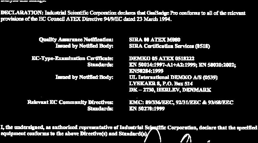


77 Revision 3.0 (p/n: ) INDUSTRIAL SCIENTIFIC 77
Activation Operation Troubleshooting Part Number: Edition: Release Date:
 Personal Single Gas Monitor Activation Operation Troubleshooting Part Number: Edition: Release Date: 17123100-1 8 July 21, 2017 Table of Contents Warnings and Cautionary Statements... 4 Recommended Practices...
T82. Instruction Manual. Single Gas Monitor GUARANTEED. FOR LIFE. P/N REV 0 PRINTED ,000 Specifications Subject to Change
 P/N 1709-4756 REV 0 PRINTED 0601-5,000 Specifications Subject to Change Single Gas Monitor T82 GUARANTEED. FOR LIFE. 1001 Oakdale Road, Oakdale, PA 15071-1500 (412) 788-4353 Toll Free 1-800-DETECTS FAX
GasAlertMicroClip X3 Specifications
 GasAlertMicroClip X3 Specifications The instrument must satisfy the following: Physical Specifications Size (h x w x d) Physical size shall be no larger than 4.4 x 2.4 x 1.2 in. / 11.3 x 6.0 x 3.2 cm Weight
CO2 RESPONDER Portable Carbon Dioxide Detector QUICK REFERENCE GUIDE
 CO2 RESPONDER Portable Carbon Dioxide Detector QUICK REFERENCE GUIDE GasAlertMicro 5 IR from Refer to for more details. Manual provided on CD with unit at time of purchase 2 Table of Contents Getting Started.
ToxiRAE II. PGM-1100 Series Personal Toxic Gas Monitor. User Manual
 ToxiRAE II PGM-1100 Series Personal Toxic Gas Monitor User Manual 045-4003-000, Rev C May 2007 - READ BEFORE OPERATING - This manual must be carefully read by all individuals who have or will have the
User Manual. Single Gas Detector
 Single Gas Detector Limited Warranty and Limitation Liability BW Technologies LP (BW) warrants the product to be free from defects in material and workmanship under normal use and service for a period
Product Manual. The Essential Guide for Safety Teams and Instrument Operators
 Product Manual The Essential Guide for Safety Teams and Instrument Operators Part Number: 17154993-1 Edition: 6 January 1, 2016 Industrial Scientific Corporation. Pittsburgh, PA USA Shanghai, China 2012,
IMR IX176 Portable Gas Detector User Manual
 IMR Portable Gas Detector User Manual Read this manual carefully before using this device. (727) 328-2818 / (800) RING-IMR Fax: (727) 328-2826 www.imrusa.com Ver. 1.0A4 CONTENTS SERVICE GUIDELINES... 3
SC-01 Operator s Manual
 SC-01 Operator s Manual Part Number: 71-0136RK Revision: D Released: 4/7/17 www.rkiinstruments.com WARNING Read and understand this instruction manual before operating instrument. Improper use of the gas
ToxiPro. Single Gas Detector. Reference Manual
 ToxiPro Single Gas Detector Reference Manual BW Technologies America 405 Barclay Blvd Lincolnshire, IL 60069 (800) 711-6776 Fax (800) 995-4992 Part number 13-264-N3 Version 3 19-August-2012 THE TOXIPRO
Single Gas Detector. Quick Reference Guide
 Single Gas Detector Quick Reference Guide Limited Warranty and Limitation Liability BW Technologies LP (BW) warrants the product to be free from defects in material and workmanship under normal use and
Using the QRAE Plus personal multigas monitor
 Using the QRAE Plus personal multigas monitor Firmware v 1.10 QRAE Plus The Hazardous Environment Detection Company QRAE Plus features Turning on the QRAE Plus Recommended Daily Start-up Procedure User
Technical Reference Guide. 1, 2, 3, and 4-Gas Detector
 Technical Reference Guide 1, 2, 3, and 4-Gas Detector Introduction 1 Zeroing the Sensors 1 Contacting BW Technologies by Honeywell 2 Safety Information - Read First 2 Sensor Poisons and Contaminants 5
GasAlert. Introduction. WWarning. Table 1. GasAlert Models. Gas Monitored
 Introduction Table 1. GasAlert Models WWarning To ensure your personal safety, read Safety Information before you use the detector. The GasAlert gas detector ( the detector ) warns of hazardous gas at
GasAlertMicro 5 and GasAlertMicro 5 PID O 2, CO, H 2 S, PH 3, SO 2, Cl 2, NH 3, NO 2, HCN, ClO 2, O 3, VOC, and Combustibles
 GasAlertMicro 5 and GasAlertMicro 5 PID O 2, CO, H 2 S, PH 3, SO 2, Cl 2, NH 3, NO 2, HCN, ClO 2, O 3, VOC, and Combustibles 1, 2, 3, 4, and 5 Gas Detectors Quick Reference Guide Limited Warranty & Limitation
GasAlertMicro 5. 1, 2, 3, 4, and 5 Gas Detectors. Quick Reference Guide
 O 2, CO, H 2 S, PH 3, SO 2, Cl 2, NH 3, NO 2, HCN, ClO 2, O 3, VOC, and Combustibles 1, 2, 3, 4, and 5 Gas Detectors Quick Reference Guide Limited Warranty & Limitation of Liability BW Technologies Ltd.
S ing le G a s D etec tor. R eferenc e M a nua l
 ToxiP ro S ing le G a s D etec tor R eferenc e M a nua l GasTech Australia Pty Ltd 24 Baretta Rd Wangara Western Australia 6065 Tel 1800 999 902 Fax 1800 999 903 http://www.gastech.com.au THE TOXIPRO PERSONAL
ToxiRAE II. PGM-1100 Series Personal Toxic Gas Monitor. User Manual
 ToxiRAE II PGM-1100 Series Personal Toxic Gas Monitor User Manual 045-4003-000, Revision B, March 2005 - READ BEFORE OPERATING - This manual must be carefully read by all individuals who have or will have
Bacharach Bodyguard 4 User's Guide
 Bacharach Bodyguard 4 User's Guide This manual and the software described in it are copyrighted, with all rights reserved. Under the copyright laws, this manual or the software may not be copied, in whole
ALTAIR 5X Multigas Detector Product Specification
 ALTAIR 5X Multigas Detector Product Specification PHYSICAL CHARACTERISTICS Gas delivery Size, pumped unit without IR Size, pumped unit with IR Weight Handling Case material Environmental protection Display
Multi-gas Monitor. Product Manual Set-up Operation Service. Part Number: Version 12
 Multi-gas Monitor Product Manual Set-up Operation Service Part Number: 17152357-1 Version 12 1 Table of Contents COPYRIGHT NOTICE... 3 WARNINGS AND CAUTIONARY STATEMENTS... 3 General... 3 Personnel...
Safe Operation Manual. Honeywell IQ Force Gas Detector
 Safe Operation Manual Honeywell IQ Force Gas Detector Honeywell Analytics 800-663-4164 403-248-9226 Fax 403-575-3708 03JUN2012 P/N 50105843-047 Version 01 http://www.honeywell.com HONEYWELL IQ Force PERSONAL
1, 2, 3, and 4-Gas Detector. Technical Reference Guide
 1, 2, 3, and 4-Gas Detector Technical Reference Guide Limited Warranty and Limitation Liability BW Technologies LP (BW) warrants the product to be free from defects in material and workmanship under normal
QUICK REFERENCE GUIDE
 - 4GAS RESPONDER Confined Space Entry Portable Gas Detector QUICK REFERENCE GUIDE 4-GAS RESPONDER GasAlertMicro 5 from Refer to for more details. Manual provided on CD with unit at time of purchase 2 Table
Single Gas Monitor 777
 Single Gas Monitor 777 Carbon Monoxide The Value Leader TM www.tpi-thevalueleader.com Contents Agency Listings... 1 Safety Information... 2 General Description & Physical Specifications... 3 Product Features...4
X5 Personal Gas Detector. Operating Manual
 X5 Personal Gas Detector X5 Operating Manual Limited Warranty and Limitation of Liability All products are designed and manufactured to the latest internationally recognized standards by Honeywell Analytics
Sirius MultiGas Detector
 Sirius MultiGas Detector Operating Manual In North America, to contact your nearest stocking location, dial toll-free 1-800-MSA-2222 To contact MSA International, dial 1-412-967-3354 or 1-800-MSA-7777
E1000 Portable gas detector
 E1000 Portable gas detector Operation manual Ver:HWWM161229CG Read this manual carefully before using the device Table of Contents SAFETY INFORMATION... - 1-1. BRIEF INTRODUCTION... - 3-2. MAIN FUNCTION
BW Clip4. Portable Gas Detector. Operator Manual
 BW Clip4 Portable Gas Detector Operator Manual Safety Information Use the detector only as specified in this manual and the reference guide, otherwise the protection provided by the detector may be impaired.
ATX620. Instruction Manual. Multi-Gas Monitor. P/N REV 02 Printed Specifications Subject to Change GUARANTEED. FOR LIFE.
 P/N 1706-3389 REV 02 Printed 0103-1000 Specifications Subject to Change Multi-Gas Monitor ATX620 GUARANTEED. FOR LIFE. 1001 Oakdale Road, Oakdale, PA 15071-1500 (412) 788-4353 Toll Free 1-800-DETECTS FAX
RAE Systems Systems. User Presentation. October Protection Through Detection
 RAE Systems Systems AreaRAE Inert User Presentation October 2009 www.raesystems.com AGENDA Overview & Features Basic Operation Turning the AreaRAE Inert monitor ON Warnings NORMAL & INERT Mode Displays
Reference Manual MultiPro Gas Detector
 Reference Manual MultiPro Gas Detector GasTech Australia Pty Ltd 24 Baretta Rd Wangara Western Australia 6065 Tel 1800 999 902 Fax 1800 999 903 http://www.gastech.com.au 1 MULTIPRO PERSONAL PORTABLE GAS
SIRIUS. [ MultiGas Detector ] Instruction Manual. Manufactured by: MSA INSTRUMENT DIVISION P.O.Box 427, Pittsburgh, Pennsylvania 15230
![SIRIUS. [ MultiGas Detector ] Instruction Manual. Manufactured by: MSA INSTRUMENT DIVISION P.O.Box 427, Pittsburgh, Pennsylvania 15230](/thumbs/92/109379373.jpg "SIRIUS. [ MultiGas Detector ] Instruction Manual. Manufactured by: MSA INSTRUMENT DIVISION P.O.Box 427, Pittsburgh, Pennsylvania 15230") SIRIUS [ MultiGas Detector ] Instruction Manual Manufactured by: MSA INSTRUMENT DIVISION P.O.Box 427, Pittsburgh, Pennsylvania 15230 [Europe] Rev.03 / 11 2010 10092677 Y-HLS / GB 1 Warranty and Liability
SIRIUS [ MultiGas Detector ] Instruction Manual Manufactured by: MSA INSTRUMENT DIVISION P.O.Box 427, Pittsburgh, Pennsylvania 15230 [Europe] Rev.03 / 11 2010 10092677 Y-HLS / GB 1 Warranty and Liability
NH 3 RESPONDER Portable Ammonia Leak Detector QUICK REFERENCE GUIDE
 Portable Ammonia Leak Detector QUICK REFERENCE GUIDE Specially configured GasAlert Micro 5 PID from Refer to for more details. Manual provided on CD with unit at time of purchase 2 Table of Contents Getting
TS400. Operating Manual. Test Station for Microtector II Series (G450/G460)
") Operating Manual TS400 Test Station for Microtector II Series (G450/G460) GfG GESELLSCHAFT FÜR GERÄTEBAU MBH KLÖNNESTRASSE 99 44143 DORTMUND, Germany TEL. +49 / (0)2 31 / 5 64 00 0 FAX +49 / (0)2 31 /
Operating Manual TS400 Test Station for Microtector II Series (G450/G460) GfG GESELLSCHAFT FÜR GERÄTEBAU MBH KLÖNNESTRASSE 99 44143 DORTMUND, Germany TEL. +49 / (0)2 31 / 5 64 00 0 FAX +49 / (0)2 31 /
Reference Manual. MultiPro Gas Detector
 Reference Manual MultiPro Gas Detector Honeywell Analytics, Inc. 405 Barclay Blvd Lincolnshire, IL 60069 (800) 711-6776 (847) 955-8200 Fax (800) 995 4992 27August 2012 P/N 13-278 Version 3 www.honeywellanalytics.com
1, 2, 3, and 4-Gas Detector. Technical Reference Guide
 1, 2, 3, and 4-Gas Detector Limited Warranty and Limitation Liability BW Technologies LP (BW) warrants the product to be free from defects in material and workmanship under normal use and service for a
MX6 ibrid. Multi-gas Monitor Operation Guide. Part Number: Revision 14
 MX6 ibrid Multi-gas Monitor Operation Guide Part Number: 17130279-1 Revision 14 Release Date February 25, 2016 Industrial Scientific Corporation. Pittsburgh, PA USA Shanghai, China 2007, 2009, 2011, 2012,
multi-gas detector Go the distance, and save Wear yellow. Work safe.
 multi-gas detector Go the distance, and save GasAlertMax XT II is the smart, simple, economical way to compliance. Workers feel safe and incidents are minimized so everyone will be able to do more. That
5 Operating Modes GX Smallest 6 gas sample draw PID library of over 600 VOC s 2 Interchangable smart sensor slots
 5 Operating Modes GX-6000 Smallest 6 gas sample draw PID library of over 600 VOC s 2 Interchangable smart sensor slots CONFINED SPACE ENTRY Monitor LEL, O2, CO, and H2S Internal sample pump Pull samples
Clip SGD. Portable single Gas Detector. User manual
 Portable single Gas Detector User manual M07716 Issue 1 October 2017 WARNING Clip SGD is a hazardous area certified gas detector and as such must be operated and maintained in strict accordance with the
IMR EX610. Portable Gas Detector. Operation Manual
 IMR EX610 Portable Gas Detector Operation Manual IMR Environmental Equipment, Inc. 3634 Central Ave. St. Petersburg, FL 33711 Phone: 727-328-2818 email: info@imrusa.com Read this manual carefully before
ALTAIR 4 Four Gas Multigas Detector
 Operating Manual ALTAIR 4 Four Gas Multigas Detector Manufactured by MSA INSTRUMENT DIVISION P.O. Box 427, Pittsburgh, Pennsylvania 15230, USA P/N 10088975 WARNING Read this manual carefully before using
NH3 RESPONDER PORTABLE AMMONIA LEAK DETECTOR. Quick Reference Guide
 NH3 RESPONDER PORTABLE AMMONIA LEAK DETECTOR Quick Reference Guide 2 NH3 RESPONDER Specially configured GasAlertMicro 5 from Refer to Operating Manual for more details. Manual provided on CD with unit
Toxi Vision IR CH 4. Single Gas Detector. Reference Manual
 Toxi Vision IR CH 4 Single Gas Detector Reference Manual Sperian Instrumentation 651 South Main Street Middletown, CT 06457 (800) 711-6776 (860) 344-1079 Fax (860) 344-1068 Part number 13-316 Version 1.10
5 Operating Modes GX Smallest 6 gas sample draw PID library of over 600 VOC s 2 Interchangable smart sensor slots
 5 Operating Modes GX-6000 Smallest 6 gas sample draw PID library of over 600 VOC s 2 Interchangable smart sensor slots GX-6000 5 Operating modes Normal Leak Check Inert Bar hole Snap Log Monitor up to
ToxiPro. Single Gas Detector. Reference Manual
 ToxiPro Single Gas Detector Reference Manual Biosystems LLC 651 South Main Street Middletown, CT 06457 (800) 711-6776 (860) 344-1079 Fax (860) 344-1068 Part number 13-264 Version 1.30 29NOV2004 1 THE TOXIPRO
MODEL: SP12C7. (Portable 4 gas detector) Operating Manual
 Operating Manual") MODEL: SP12C7 (Portable 4 gas detector) Operating Manual Guarantee and Repair Senko Co., Ltd. guarantees the products of SP series for 24 months from the shipping date and repairs or replaces the defected
MODEL: SP12C7 (Portable 4 gas detector) Operating Manual Guarantee and Repair Senko Co., Ltd. guarantees the products of SP series for 24 months from the shipping date and repairs or replaces the defected
RAE Systems RAE Systems RAE Systems Presented by David Lucha RAE Systems Protectio n Through Detection
 RAE Systems y RAE Systems Presented by David Lucha Feb 10, 2012 RAE Systems Protection Through Detection How well do you know your ToxiRAE 3 Objective Understand why user are having issues / difficulties
Operations Manual TS400. Test Station for G450/G460 Gas Detector
 TS400 Test Station for G450/G460 Gas Detector Operations Manual 1194 Oak Valley Dr, Ste 20, Ann Arbor MI 48108 USA (800) 959-0329 (734) 769-0573 www.gfg-inc.com GfG Products for Increased Safety Congratulations
Dräger Pac Ex 2. Elegant and smart... Explosive hazards and lack or surplus of oxygen under control
 Dräger Elegant and smart... Explosive hazards and lack or surplus of oxygen under control Page 1 / December 2002 Two-In-One Instrument measures for explosive hazards and a lack or surplus of oxygen. It
PHD6. Flexible, comprehensive monitoring backed up by high performance functionality
 PHD6 Flexible, comprehensive monitoring backed up by high performance functionality PHD6 TM Flexible solution that adapts to meet needs Five sensor slots offering up to six channels of detection Sixteen
Dräger X-am approved as type MQG 0010 Multi-Gas Monitor Technical Manual _01.eps
 Dräger X-am 5000 approved as type MQG 0010 Multi-Gas Monitor Technical Manual 04723999_01.eps Content Content For Your Safety..................................................... 4 Safety symbols used
MiniCO, MiniH 2 S, MiniOX, MiniOX Remote, MiniCl 2. , and MiniClO 2. Responder Detectors Instruction Manual "! WARNING
 MiniCO, MiniH 2 S, MiniOX, MiniOX Remote, MiniCl 2 TM, and MiniClO 2 TM Responder Detectors Instruction Manual "! WARNING THIS MANUAL MUST BE CAREFULLY READ BY ALL INDIVIDUALS WHO HAVE OR WILL HAVE THE
Operations Manual TS400. Test Station for G450/G460 Gas Detector
 TS400 Test Station for G450/G460 Gas Detector Operations Manual 1194 Oak Valley Dr, Ste 20, Ann Arbor MI 48108 USA (800) 959-0329 (734) 769-0573 www.goodforgas.com GfG Products for Increased Safety Congratulations
TMX 412. Instruction Manual. Multi-Gas Monitor. P/N REV 11 Printed Specifications Subject to Change
 P/N 1705-0816 REV 11 Printed 0228 2010 Specifications Subject to Change Multi-Gas Monitor TMX 412 1001 Oakdale Road, Oakdale, PA 15071-1500 (412) 788-4353 Toll Free 1-800-DETECTS FAX 412-788-8353 Instruction
Operator s Manual. 1, 2, 3, and 4-Gas Detector
 Operator s Manual 1, 2, 3, and 4-Gas Detector Limited Warranty and Limitation Liability BW Technologies LP (BW) warrants the product to be free from defects in material and workmanship under normal use
Issue 4 10/10/11. Part Number: 48160
 User Handbook SHIPSURVEYOR USER HANDBOOK Issue 4 10/10/11 Part Number: 48160 GMI welcomes comments on all our publications. Your comments can be of great value in helping us to improve our customer publications.
03 Series: OX-03, CO-03, HS-03 Versions Operator s Manual
 03 Series: OX-03, CO-03, HS-03 Versions Operator s Manual Part Number: 71-0304 Revision: A Released: 7/31/15 www.rkiinstruments.com WARNING Read and understand this instruction manual before operating
Macurco Single-Gas XL Series Monitor, CM-1XL Carbon Monoxide (CO), HS-1XL Hydrogen Sulfide (H2S) User Instructions
, HS-1XL Hydrogen Sulfide (H2S) User Instructions") Macurco Single-Gas XL Series Monitor, CM-1XL Carbon Monoxide (CO), HS-1XL Hydrogen Sulfide (H2S) User Instructions Important: Keep these User Instructions for reference 2 TABLE OF CONTENTS GENERAL SAFETY
Macurco Single-Gas XL Series Monitor, CM-1XL Carbon Monoxide (CO), HS-1XL Hydrogen Sulfide (H2S) User Instructions Important: Keep these User Instructions for reference 2 TABLE OF CONTENTS GENERAL SAFETY
OUR MISSION. Design - Manufacture - Sell: Highest quality products for the preservation of life and property.
 OUR MISSION Design - Manufacture - Sell: Highest quality products for the preservation of life and property. Provide: Best customer service available. Dear Valued Customer: Thank you for buying and using
Dräger X-am approved as type MQG 01** Multi-Gas Monitor. Technical Handbook. CO2 Vol% CH4 %UEG. CO ppm. ppm NH _01.
 Dräger X-am 5600 approved as type MQG 01** Multi-Gas Monitor Technical Handbook CO2 CH4 %UEG O2 CO H2S NH3 04733072_01.eps Content Content For Your Safety......................................................4
Dräger X-am 2500 (MQG 0011) Technical Manual
 Technical Manual") Dräger X-am 2500 (MQG 0011) Technical Manual i Content Content 1 For your safety............................4 1.1 General safety statements....................4 1.2 Definitions of alert icons......................4
Dräger X-am 2500 (MQG 0011) Technical Manual i Content Content 1 For your safety............................4 1.1 General safety statements....................4 1.2 Definitions of alert icons......................4
Pioneer-R16 Gas Monitor Operator s Manual
 Pioneer-R16 Gas Monitor Operator s Manual Edition 7/2/97 RKI INSTRUMENTS, INC RKI Instruments, Inc. 33248 Central Ave, Union City, CA 94587 (510) 441-5656 Chapter 1: Description About the Pioneer-R16 Gas
Operate the Mutli-Gas Monitor PID
 TASK: Operate the Multi-Gas Monitor Learning Objective CONDITION: In a classroom environment, given a fully charged Multi-gas Monitor with the manufacturer operator s manual, all monitor components/accessories,
Operator s Manual. 1, 2, 3, and 4-Gas Detector
 Operator s Manual 1, 2, 3, and 4-Gas Detector Limited Warranty and Limitation Liability BW Technologies LP (BW) warrants the product to be free from defects in material and workmanship under normal use
Single Gas Clip and SGC Plus User s Manual Rev 2.1 READ FIRST BEFORE OPERATION WARNING STATEMENTS / AVERTISSEMENT Activating tthe detector for the
 Single Gas Clip and SGC Plus User s Manual Rev 2.1 READ FIRST BEFORE OPERATION Gas Clip Technologies (GCT) Single Gas Clip and SGC Plus detectors are personal safety devices designed to detect the presence
PGM100 Carbon Monoxide
 Single Gas Monitor PGM100 Carbon Monoxide The Value Leader TM www.tpi-thevalueleader.com Contents Agency Listings... 1 Safety Information... 2 General Description & Physical Specifications... 3 Product
Operating Instructions Compur Monitox plus
 Operating Instructions Compur Monitox plus Subject to changes without notice. Copyright Compur Monitors München Editor: Compur Monitors GmbH & Co. KG Weissenseestr. 101 D-81539 München Content Page Monitox
ENMET Corporation. PO Box 979 Ann Arbor, MI RECON. Manual. Manual Part Number MCN-410, 12/03/08
 PO Box 979 Ann Arbor, MI 48106-0979 RECON Manual Manual Part Number 80006-018 MCN-410, 12/03/08 Table of Contents 1.0 INTRODUCTION... 1 1.1 UNPACK... 1 1.2 CHECK ORDER... 1 1.3 SERIAL NUMBERS... 1 2.0
GasAlertMicro 5 / PID / IR
 GasAlertMicro 5 / PID / IR O 2, CO, H 2 S, PH 3, SO 2, Cl 2, NH 3, NO 2, HCN, ClO 2, O 3, VOC, CO 2 and Combustibles 1, 2, 3, 4, and 5 Gas Detectors User Manual Limited Warranty & Limitation of Liability
MGC Dock User s Manual
 Operator s Manual Contents Warnings Statements/Avertisseement... 3 READ FIRST BEFORE OPERATION... 3 Basic Operation... 4 Clip Dock Components... 4 LEDs... 4 Operation... 5 Turning the Clip Dock On and
G450. Multi-gas Detector. Field Operation Manual Oak Valley Dr, Ste 20, Ann Arbor MI USA (800) (734)
 (734)") G450 Multi-gas Detector Field Operation Manual 1194 Oak Valley Dr, Ste 20, Ann Arbor MI 48108 USA (800) 959-0329 (734) 769-0573 www.gfg-inc.com Warranty GfG Instrumentation warrants our products to be
G450 Multi-gas Detector Field Operation Manual 1194 Oak Valley Dr, Ste 20, Ann Arbor MI 48108 USA (800) 959-0329 (734) 769-0573 www.gfg-inc.com Warranty GfG Instrumentation warrants our products to be
UltraRAE 3000 Basic Operation Pocket Reference
 UltraRAE 3000 Basic Operation Pocket Reference PN: 059-4025-000 Rev. A May 2008 Read Before Operating This Pocket Reference is intended as a quick guide to basic use and calibration of your instrument.
DI220 Using the Optional Docking Station The maintenance and operating functions of the Micro IV can be automated with the Micro IV Docking Station.
 DI220 Using the Optional Docking Station The maintenance and operating functions of the Micro IV can be automated with the Micro IV Docking Station. The following steps outline the correct sequence to
1.1 Definitions of alert icons. For your safety
 For your safety 1 For your safety Before using this product, carefully read these Instructions for Use and those of the associated products. Strictly follow the Instructions for Use. The user must fully
Reference Manual. MultiVision Gas Detector
 Reference Manual MultiVision Gas Detector Sperian Instrumentation 651 South Main Street Middletown, CT 06457 800 711-6776 860 344-1079 Fax 860 344 1068 24SEPT2008 P/N 13-230 Version 2.01 http://www.biosystems.com
MiniRAE 3000 ppbrae Basic Operation Pocket Reference
 MiniRAE 3000 ppbrae 3000 Basic Operation Pocket Reference PN: 059-4030-000-D Rev. B August 2010 Read Before Operating This Pocket Reference is intended as a quick guide to basic use and calibration of
INNOVA Series INSTRUCTION MANUAL P/N REV. D
 INNOVA Series INSTRUCTION MANUAL P/N 71-6417 REV. D THERMO ELECTRON CORPORATION ENVIRONMENTAL INSTRUMENTS 27 FORGE PARKWAY FRANKLIN MASSACHUSETTS 02038 (866) 282-0430 Toll Free (508) 520-0430 International
GLD-30 Gas Leak Detector
 GLD-30 Gas Leak Detector Installation, Operation & Maintenance General: The Archer Instruments GLD-30 is an ambient air monitor, used to detect the presence of a target gas (or gases) and to alert operators
OI-2400-DOCK Multi Gas Docking Station. Operation Manual trevision 2.2w
 OI-2400-DOCK Multi Gas Docking Station Operation Manual trevision 2.2w Table of Contents Introduction... 3 Warnings Statements/Avertisseement... 4 Basic Operation... 5 OI-2400-DOCK Components... 5 LEDs...
Dräger X-am Dräger X-am 7000: Modular, rugged and waterproof.
 DETECTION PERSONAL PROTECTION DIVING TECHNOLOGY SYSTEM TECHNOLOGY SERVICES Dräger X-am 7000 ST-2660-2003 Dräger X-am 7000 is the innovative solution for the simultaneous and continuous detection of up
SENSIT GOLD G2 II 2 G INSTRUCTION MANUAL. Gas Detection Instrument. Read and understand instructions before use.
 INSTRUCTION MANUAL SENSIT GOLD G2 Gas Detection Instrument For use with combustible gases and optionally available oxygen and toxic gases. Read and understand instructions before use. II 2 G 0891 Ex ib
EAGLE 2. 6 Channel Capacity. Inlet fitting. Loud buzzer (95dB) IrDA communication port Low flow shutoff and alarm Alarm LED s with wide visibility
 IrDA communication port Low flow shutoff and alarm Alarm LED s with wide visibility") EAGLE 2 Inlet fitting Loud buzzer (95dB) IrDA communication port Low flow shutoff and alarm Alarm LED s with wide visibility Internal / external hydrophobic filters Self healing polyurethane protective
EAGLE 2 Inlet fitting Loud buzzer (95dB) IrDA communication port Low flow shutoff and alarm Alarm LED s with wide visibility Internal / external hydrophobic filters Self healing polyurethane protective
Carbon Monoxide Transmitter
 Introduction The CO Transmitter uses an electrochemical sensor to monitor the carbon monoxide level and outputs a field-selectable 4-20 ma or voltage signal. The voltage signal may also be set to 0-5 or
altair 2X Gas Detectors
 altair 2X Gas Detectors i t S W H at S i n S i d E t H at REALLY co u n t S + = XCell Pulse Technology With our patented* Xcell pulse technology, we have created a simple and inexpensive approach to bump
Biosystems ToxiLtd. Single Gas Detector. Reference Manual
 Biosystems ToxiLtd Single Gas Detector Reference Manual 0 Sperian Instrumentation 651 South Main Street Middletown, CT 06457 (800) 711-6776 (860) 344-1079 Fax (860) 344-1068 Part number 13-266-N Version
INNOVA Series. Instruction Manual Part Number
 INNOVA Series Instruction Manual Part Number 71-6417 5Aug2009 2007 Thermo Fisher Scientific Inc. All rights reserved. Specifications, terms and pricing are subject to change. Not all products are available
SENSIT GOLD G2 INSTRUCTION MANUAL For use with combustible gases and optionally available oxygen and toxic gases.
 PARTS AND ACCESSORIES Standard Accessories (included) Carrying Case, Alkaline Batteries, Wrist Strap, Extra Sensor Cap with O-Rings, T10 Torx Wrench and Instruction Manual Accessories and Replacement Parts
Follett Performance Plus
 Follett Performance Plus touchscreen user guide The next level of control in undercounter refrigeration Controller Operation - Performance Plus touchscreen Use and care of the LCD Performance Plus touchscreen
ALTAIR 2X Gas Detectors It s what s inside that really counts
 ALTAIR 2X Gas Detectors It s what s inside that really counts Because every life has a purpose The ALTAIR 2X Gas Detector The ALTAIR 2X Gas Detector is the first one or two gas detector that incorporates
altair 2X Gas Detectors
 altair 2X Gas Detectors i t S W H at S i n S i d E t H at R E A L LY co u n t S Because every life has a purpose... + = XCell Pulse Technology With our patented* Xcell pulse technology, we have created
Confined Space Monitoring. Leak Investigation. Functions 4. Bar Hole Sampling. Line Purge Testing. Actual Size GX-2012
 Confined Space Monitoring Leak Investigation 1 Functions 4 Bar Hole Sampling Line Purge Testing Actual Size GX-2012 3 Operating Modes Internal sample draw pump with 50 range Low flow alarm 3 bright visual
SENSIT HXG-2d. SENSIT TECHNOLOGIES 851 Transport Drive Valparaiso, IN Phone: (219) Fax: (219)
 Fax: (219)") WARRANTY AND REPAIR POLICY Your SENSIT HXG-2d instrument is warranted to be free from defects in materials and workmanship for a period of two years after purchase (excluding sensor, calibration and batteries).
WARRANTY AND REPAIR POLICY Your SENSIT HXG-2d instrument is warranted to be free from defects in materials and workmanship for a period of two years after purchase (excluding sensor, calibration and batteries).
For the Safety of Your
 For the Safety of Your Team in Confined Spaces CSM 5000 Portable Multi-Gas Monitor H 2 S OX CO EX Do it Right Do it Safe Power/Select Button Used for turning the CSM 5000 ON and OFF, accessing download
MDU 420. Instruction Manual. Dual Range Methane Monitor. P/N REV 0 Printed Specifications Subject to Change
 P/N 1705-2583 REV 0 Printed 0297-2000 Specifications Subject to Change Dual Range Methane Monitor MDU 420 GUARANTEED. FOR LIFE. 1001 Oakdale Road, Oakdale, PA 15071-1500 (412) 788-4353 Toll Free 1-800-DETECTS
Innova Series Operator s Manual
 Innova Series Operator s Manual PROPRIETARY STATEMENT Thermo GasTech owns proprietary rights in the information disclosed within. By receiving this document, the recipient agrees that neither this document
Warranty Registration
 WARRANT Y AND LIMITS OF LIABILIT Y Vulcain Inc. warrants to the original purchaser that its product, and the component parts thereof, will be free from defects in workmanship and materials for a period
Single Gas Clip and SGC Plus User s Manual Rev 2.3
 Single Gas Clip and SGC Plus User s Manual Rev 2.3 READ BEFORE OPERATION Gas Clip Technologies (GCT) Single Gas Clip and SGC Plus detectors are personal safety devices designed to detect the presence of
Using the MiniRAE 2000 & ppbrae PID
 MiniRAE 2000 Using the MiniRAE 2000 & ppbrae PID Firmware v. 1.20 (rev C) The Hazardous Environment Detection Company Training Agenda: MiniRAE 2000 & ppbrae features Turning on the MiniRAE 2000 & ppbrae