GASGUARD VENT LINE3. Ammonia Sensor OPERATING & INSTALLATION MANUAL
|
|
|
- Sharon Johnson
- 5 years ago
- Views:
Transcription


1 GASGUARD VENT LINE3 Ammonia Sensor OPERATING & INSTALLATION MANUAL

2 Operating and Installation Manual Warning Use this product only in the manner described in this manual. If the equipment is used in a manner not specified by Calibration Technologies, the protection provided by the equipment may be impaired. This equipment should be installed by qualified personnel. 2
3 Operating and Instruction Manual Table of Contents General description. 4 Installation.. 4 Locating the sensor. 4 Installation guidelines 5 Wiring.. 6 Operation.. 7 Start-up.. 7 Calibration.. 7 Maintenance. 9 Troubleshooting.. 10 Specifications.. 10 Warranty.. 11 For technical support, contact: Calibration Technologies 920 N Trade Winds Pkwy Columbia, MO sales@ctiengineering.com 3
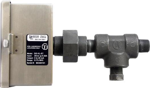
4 Operating and Installation Manual General Description The GasGuard VL-NH3 sensor is a +24 VDC, threewire, 4/20 ma sensor for ammonia. It provides an industry standard linear 4/20 ma output signal compatible with most gas detection systems and PLCs. The GasGuard VL-NH3 provides real-time continuous monitoring of ammonia vapors in refrigeration system vent lines. Utilizing a rugged and long-life solid-state sensor, the GasGuard VL-NH3 sensor can withstand continuous exposures to high concentrations of ammonia vapors, without shortening the life of the sensor. The sensor is housed in the mounting kit, which is connected to the backside of the sensor enclosure. The union of the mounting kit breaks apart allowing for simple sensor field replacement. The transmitter circuit board is sealed in potting compound, protecting sensitive electronic components and copper tracing from corrosion. The stainless steel enclosure protects the transmitter from chemical and UV damage. Recommended alarm setpoints for ammonia system vent lines are typically % NH3 (12 20 ma). Setpoints lower than this may result in occasional false alarms due to inclement weather or interference gases (i.e. truck exhaust, condenser steam, etc.) Locating the sensor Installation Warning: Outdoor installation only. Never install the sensor indoors (i.e., Engine Room) Note: The ½ nipple of the supplied mounting kit should be welded to the relief header to allow airflow to the sensor. Note: Removing the ½ plug from the mounting kit usually allows more fresh air to the sensor and prevents signal rise over time. Discharging to Atmosphere The GasGuard VL-NH3 sensor assembly should be installed outdoors three to five feet above the roofline, where the relief header discharges to the atmosphere (see Figure 1). Discharging to Water Tank The GasGuard VL-NH3 sensor assembly should be installed on the atmospheric vent on top of the water tank (see Figure 2). This type of installation will not catch the weeping relief valves, but will detect ammonia vapors from the water during a release event. 4
5 Operating and Instruction Manual Union Nipple Relief header Mount sensor opposite side of discharge Installation Guidelines: Always assume system could discharge at any moment. Stay clear of discharge path and have escape route planned. Make sure ammonia does not discharge onto sensor assembly or personnel working on sensor (i.e. mount sensor opposite side of discharge). Install sensor enclosure with conduit hole facing down. Relief header Atmospheric vent ½ plug Sensor cable 3 5 Water tank Roofline Figure 1: Discharge to Atmosphere Figure 2: Discharge to Water Tank 5
.")
6 Operating and Installation Manual Wiring Electrical wiring must comply with all applicable codes. Electrical Power: 24 VDC regulated, 250 ma. Output: Linear 4/20 ma output. Monitoring equipment may have a maximum input impedance of 700 ohms. Cable Recommendation: 20/3 shielded cable (General Cable C2525A or equivalent). Length of cable to sensor should be no greater than 1,500 feet. Monitoring: Monitoring equipment must be configured to indicate a fault if the signal is below 1 ma. All signals over 20 ma must be considered high gas concentrations. Alarm setpoints should not be lower than 50% of full-scale range. Wiring Guidelines: Use only the existing conduit hole for connections to the sensor. Always use three-conductor, insulated, stranded, shielded copper cable. Do not pull sensor wiring with AC power cables. This can cause electrical interference. If cable runs cannot be made without a splice, all splice connections should be soldered. Ground the shield at the main control panel. Connect the shield wire in the sensor terminal block labeled SHLD. Always disconnect power at the controller before performing any wiring at the sensor. 6 Figure 3: Wiring diagram
7 Operating and Instruction Manual Operation Start-up Before applying power, make a final check of all wiring for continuity, shorts, grounds, etc. It is usually best to disconnect external alarms and other equipment from the sensor until the initial start-up procedures are completed. After power-up, allow at least 1 hour for the system to stabilize before testing the sensors. Because sensors are normally located at a distance from the main unit, the test time required and accuracy of the response checks will be improved if two people perform the startup procedures and use radio contact. Response Test: 1. One person removes the ½ plug in the tee and injects a small amount of propane/butane from an unlit plumber s torch. 2. The second person stays at the control panel to determine that each sensor, when exposed to the gas, is connected to the proper input and responds, causing appropriate alarm functions. Calibration The GasGuard VL-NH3 Sensor comes factory calibrated and should not require any adjustments after installation. If any adjustments are required, there are two pots on the preamp that are used for calibration. Note: Never measure sensor output in ma. Always use mvdc or VDC voltmeter settings. Zero Calibration: After the unit is installed and has been powered up for a minimum of 12 hours, the unit can be zero calibrated by the following: Be sure the unit is in clean air with no noticeable ammonia vapors. Adjust the zero pot until the sensor outputs 40 mv from Test [-] to Test [+] (see Figure 4). Span Calibration: It is recommended that the GasGuard VL-NH3 sensor be response tested only, every six months. Refer to the Response Test procedure on this page. If span calibration is required, the following procedure will span the unit: Unscrew the union nut of mounting kit, making sure to support weight of sensor assembly. This will expose the sensor and allow for a more accurate span calibration (see Figure 5). Apply 1% NH3 span gas at 0.8 L/min. Once the output signal has peaked (or one minute maximum) adjust the span pot until the sensor outputs 200 mv from Test [-] to Test [+] (see Figure 4). 7

8 Operating and Installation Manual 8 Figure 4: Sensor output and zero/span adjustments


9 Operating and Instruction Manual Maintenance The GasGuard VL-NH3 was designed for long life and minimal maintenance. Calibration Technologies recommends the following maintenance schedule: Maintenance Guidelines: The sensor is shipped with a factory calibration and should be response tested every 6 months. Response-test the sensor at least once every 6 months. The response test can be performed with propane or butane from an unlit plumber s torch. All tests and calibrations must be logged. Always disconnect power at the controller before performing any wiring at the sensor. Sensor Life: Typical sensor life of the GasGuard VL- NH3 sensor is five to seven years. A few conditions can cause the sensor to become faulty, including: a long period of time exposure to liquid 1. Loosen the screw terminals of sensor connector (orange and red wires) and disconnect the wires. 2. Unscrew the union nut of mounting kit, making sure to support weight of sensor assembly. This will expose the sensor. 3. Remove sensor by pulling it out through the union. 4. Install new sensor and tighten sensor screw terminals. Make sure the red and orange wires are in their correct terminals. 5. Re-assemble sensor/mounting kit. 6. Discard old sensor. The sensor can be response-tested immediately after replacement. Zero/span calibration may be performed after a 12 hour warm-up period. Union nut Sensor Mounting kit with union, tee, nipple and test plug Sensor Replacement: When the sensor becomes faulty, a replacement sensor can be obtained from Calibration Technologies. To replace the sensor, refer to Figure 5 and the following procedure. Note: Always assume system could discharge at any moment. Stay clear of discharge path and have escape route planned. Figure 5: Sensor replacement 9
10 Operating and Installation Manual Troubleshooting Sensor Fault: (low signal reading) Indications: (any or all) Red LED on transmitter lit. Voltage signal at testpoints is 5 mvdc (.5 ma output). PLC displays negative value (i.e., ppm). Controller indicates sensor fault or sensor failure Possible Cause / Solution: Sensor exposed to liquid. Replace sensor element (see page 9 for more info). Loose connection. Check and tighten sensor wires. Constant or Intermittent high signal or alarms: Indications: Erratic or constant high concentration reading at controller or PLC. Possible Cause / Solution: Weeping relief valve. Check valve by drawing a sample from the header with an accurate portable ammonia detector. Be sure to sample 1 to 3 from inside the header to ensure a good reading. or loosen union nut and remove sensor assembly from header. If signal returns to normal in fresh air, investigate relief valve(s) and replace if necessary. Condenser steam. Re-install the ½ plug or install pipe in its place, lowered below the condenser steam level to allow a fresh-air vent to the sensor. Sensor aged beyond its useful life (hypersensitive). Replace sensor element (see page 9 for more info). Specifications Input Power: +24 VDC, 250 ma Detection Principle: Solid-state Detection Method: Diffusion Gas: Ammonia (NH3) Range: 0/1% (10,000 ppm) Output Signal: Linear 4/20 ma (max input impedance: 700 Ohms) Deadband: 0.5% NH3 (12 ma or 50% full-scale) Response Time: T 90 = less than 30 seconds Accuracy: +/- 5% of full-scale Zero Drift: Less than 1% per month Span Drift: Less than 1% of full-scale per month Linearity: +/- 5% of full-scale Repeatability: +/- 5% of full-scale Wiring Connections: 3-conductor, shielded, stranded, 20 AWG cable (General Cable C2525A or equivalent) up to 1500 ft. Terminal Block Plug (Field Wiring): AWG, torque 4 lbs-in. Enclosure: 18 ga stainless steel housing. Captive screw in hinged lid. For non-classified areas. Mounting Kit: Schedule 80 NPT pipe fittings Temperature Range: -46 F to +140 F (-44 C to +60 C) Dimensions: 4.8 high x 4.72 wide x 3.35 deep Weight: 4 lbs (includes mounting kit) Certification: ETL Listed: Confirms to UL Certified to CSA C22.2 No
11 Limited Warranty & Limitation of Liability Calibration Technologies, Inc. (CTI) warrants this product to be free from defects in material and workmanship under normal use and service for a period of 2 years (including sensor), beginning on the date of shipment to the buyer. This warranty extends only to the sale of new and unused products to the original buyer. CTI s warranty obligation is limited, at CTI s option, to refund of the purchase price, repair, or replacement of a defective product that is returned to a CTI authorized service center within the warranty period. In no event shall CTI s liability hereunder exceed the purchase price actually paid by the buyer for the Product. This warranty does not include: a) gas sensors that have been wetted by liquid ammonia, oil or water b) routine replacement of parts due to the normal wear and tear of the product arising from use; c) any product which in CTI s opinion, has been misused, altered, neglected or damaged by accident or abnormal conditions of operation, handling or use; d) any damage or defects attributable to repair of the product by any person other than an authorized dealer or contractor, or the installation of unapproved parts on the product The obligations set forth in this warranty are conditional on: a) proper storage, installation, calibration, use, maintenance and compliance with the product manual instructions and any other applicable recommendations of CTI; b) the buyer promptly notifying CTI of any defect and, if required, promptly making the product available for correction. No goods shall be returned to CTI until receipt by the buyer of shipping instructions from CTI; and c) the right of CTI to require that the buyer provide proof of purchase such as the original invoice, bill of sale or packing slip to establish that the product is within the warranty period. THE BUYER AGREES THAT THIS WARRANTY IS THE BUYER S SOLE AND EXCLUSIVE REMEDY AND IS IN LIEU OF ALL OTHER WARRANTIES, EXPRESS OR IMPLIED, INCLUDING BUT NOT LIMITED TO ANY IMPLIED WARRANTY OF MERCHANTABILITY OR FITNESS FOR A PARTICULAR PURPOSE. CTI SHALL NOT BE LIABLE FOR ANY SPECIAL, INDIRECT, INCIDENTAL OR CONSEQUENTIAL DAMAGES OR LOSSES, INCLUDING LOSS OF DATA, WHETHER ARISING FROM BREACH OF WARRANTY OR BASED ON CONTRACT, TORT OR RELIANCE OR ANY OTHER THEORY. 11


12 GG-VL-NH
GG-VL-R REFRIGERANT VENT LINE SENSOR. Installation and Operation Manual
 GG-VL-R REFRIGERANT VENT LINE SENSOR Installation and Operation Manual 2 GG-VL-R Warning Use this product only in the manner described in this manual. If the equipment is used in a manner not specified
GG-NH3-2% AMMONIA GAS SENSOR. Installation and Operation Manual
 GG-NH3-2% AMMONIA GAS SENSOR Installation and Operation Manual 2 GG-NH3-2% Warning Use this product only in the manner described in this manual. If the equipment is used in a manner not specified by Calibration
GG-NH3 AMMONIA GAS SENSOR. Installation and Operation Manual
 GG-NH3 AMMONIA GAS SENSOR Installation and Operation Manual 2 GG-NH3 Warning Use this product only in the manner described in this manual. If the equipment is used in a manner not specified by Calibration
GASGUARD NH 3 2% Ammonia Sensor OPERATING & INSTALLATION MANUAL
 GASGUARD NH 3 2% Ammonia Sensor OPERATING & INSTALLATION MANUAL 2 Table of Contents GasGuard NH 3 2% General description. 4 Installation.. 4 Locating the sensor. 4 Installation guidelines 5 Wiring.. 6
GG-H2S HYDROGEN SULFIDE GAS SENSOR. Installation and Operation Manual
 GG-H2S HYDROGEN SULFIDE GAS SENSOR Installation and Operation Manual 2 GG-H2S Warning Use this product only in the manner described in this manual. If the equipment is used in a manner not specified by
GASGUARD H 2-1% Hydrogen Sensor OPERATING & INSTALLATION MANUAL
 GASGUARD H 2-1% Hydrogen Sensor OPERATING & INSTALLATION MANUAL 2 Table of Contents GasGuard H 2-1% General description. 4 Installation.. 4 Locating the sensor. 4 Installation guidelines 5 Wiring.. 6 Operation..
GASGUARD O 2. Oxygen Sensor OPERATING & INSTALLATION MANUAL
 GASGUARD O 2 Oxygen Sensor OPERATING & INSTALLATION MANUAL 2 Table of Contents General description. 4 Installation.. 4 Locating the sensor. 4 Installation guidelines 5 Wiring.. 6 Operation.. 7 Start-up...
GASGUARD NH 3. Ammonia Sensor OPERATING & INSTALLATION MANUAL
 GASGUARD NH 3 Ammonia Sensor OPERATING & INSTALLATION MANUAL Operating and Installation Manual 2 Table of Contents GasGuard NH 3 Operating and Instruction Manual General description. 4 Installation.. 4
GASGUARD Cl 2. Chlorine Sensor OPERATING & INSTALLATION MANUAL
 GASGUARD Cl 2 Chlorine Sensor OPERATING & INSTALLATION MANUAL Operating and Installation Manual 2 Table of Contents GasGuard Cl 2 Operating and Instruction Manual General description. 4 Installation..
GG-NO2 NITROGEN DIOXIDE GAS SENSOR. Installation and Operation Manual
 GG-NO2 NITROGEN DIOXIDE GAS SENSOR Installation and Operation Manual 2 GG-NO2 Warning Use this product only in the manner described in this manual. If the equipment is used in a manner not specified by
GASGUARD SO2 Sulfur Dioxide Sensor OPERATING & INSTALLATION MANUAL
 GASGUARD SO2 Sulfur Dioxide Sensor OPERATING & INSTALLATION MANUAL Operating and Installation Manual Warning Use this product only in the manner described in this manual. If the equipment is used in a
GASGUARD H2S EXP. Hydrogen Sulfide Sensor OPERATING & INSTALLATION MANUAL
 GASGUARD H2S EXP Hydrogen Sulfide Sensor OPERATING & INSTALLATION MANUAL Operating and Installation Manual Warning Use this product only in the manner described in this manual. If the equipment is used
GASGUARD LEL 3 OPERATING & INSTALLATION MANUAL
 GASGUARD LEL 3 Ammonia Sensor OPERATING & INSTALLATION MANUAL GasGuard LEL 3 Operating and Installation Manual 2 Table of Contents 3GasGuard LEL Operating and Instruction Manual General description. 4
GG-R REFRIGERANT SENSOR. Installation and Operation Manual
 GG-R REFRIGERANT SENSOR Installation and Operation Manual 2 GG-R Warning Use this product only in the manner described in this manual. If the equipment is used in a manner not specified by Calibration
GG-CO-EXP CARBON MONOXIDE SENSOR. Installation and Operation Manual
 GG-CO-EXP CARBON MONOXIDE SENSOR Installation and Operation Manual 2 GG-CO-EXP Warning Use this product only in the manner described in this manual. If the equipment is used in a manner not specified by
GG-LEL2 COMBUSTIBLE GAS SENSOR. Installation and Operation Manual
 GG-LEL2 COMBUSTIBLE GAS SENSOR Installation and Operation Manual 2 GG-LEL2 Warning Use this product only in the manner described in this manual. If the equipment is used in a manner not specified by Calibration
GG-EM ENTRANCE MONITOR. Installation and Operation Manual
 GG-EM ENTRANCE MONITOR Installation and Operation Manual 2 GG-EM Warning Use this product only in the manner described in this manual. If the equipment is used in a manner not specified by Calibration
GASGUARDIAN Channel Controller OPERATING & INSTALLATION MANUAL
 GASGUARDIAN 2 3 2-Channel Controller OPERATING & INSTALLATION MANUAL GasGuardian 2 3 Operating and Installation Manual Table of Contents General description.... 3 Installation. 3 Locating the GasGuardian-2..
GG-2 2-CHANNEL GAS DETECTION CONTROL PANEL. Installation and Operation Manual
 GG-2 2-CHANNEL GAS DETECTION CONTROL PANEL Installation and Operation Manual 2 GG-2 Warning Use this product only in the manner described in this manual. If the equipment is used in a manner not specified
MGC Dock User s Manual
 Operator s Manual Contents Warnings Statements/Avertisseement... 3 READ FIRST BEFORE OPERATION... 3 Basic Operation... 4 Clip Dock Components... 4 LEDs... 4 Operation... 5 Turning the Clip Dock On and
OI-2400-DOCK Multi Gas Docking Station. Operation Manual trevision 2.2w
 OI-2400-DOCK Multi Gas Docking Station Operation Manual trevision 2.2w Table of Contents Introduction... 3 Warnings Statements/Avertisseement... 4 Basic Operation... 5 OI-2400-DOCK Components... 5 LEDs...
MGC Dock User s Manual
 User s Manual Contents Warnings Statements/Avertisseement... 3 READ FIRST BEFORE OPERATION... 3 Description... 4 Basic Operation... 5 Clip Dock Components... 5 LEDs... 5 User Operation... 6 Turning the
CO2 RESPONDER Portable Carbon Dioxide Detector QUICK REFERENCE GUIDE
 CO2 RESPONDER Portable Carbon Dioxide Detector QUICK REFERENCE GUIDE GasAlertMicro 5 IR from Refer to for more details. Manual provided on CD with unit at time of purchase 2 Table of Contents Getting Started.
RK Carbon Monoxide Transmitter Operator s Manual
 65-2434RK Carbon Monoxide Transmitter Operator s Manual Part Number: 71-0061RK Edition: First, Revision C Released: December 2001 65-2434RK CO Transmitter 1 Product Warranty RKI Instruments, Inc., warranties
RK Carbon Monoxide Transmitter Operator s Manual
 65-2432RK Carbon Monoxide Transmitter Operator s Manual Part Number: 71-0070RK Revision: P1 Released: July 8, 2001 RKI Instruments, Inc. 1855 Whipple Road Hayward CA 94544 Phone: 800-754-5165 Fax: 510-441-5650
Single Gas Clip and SGC Plus User s Manual Rev 2.1 READ FIRST BEFORE OPERATION WARNING STATEMENTS / AVERTISSEMENT Activating tthe detector for the
 Single Gas Clip and SGC Plus User s Manual Rev 2.1 READ FIRST BEFORE OPERATION Gas Clip Technologies (GCT) Single Gas Clip and SGC Plus detectors are personal safety devices designed to detect the presence
RK Transmitter Technical Notice
 65-2450RK Transmitter Technical Notice Although this Operator s Manual was written for the 65-2400RK combustible gas LEL transmitter, the operational instructions are the same for the 65-2450RK hydrogen
RK-05 Combustible Gas Transmitter Operator s Manual
 65-2405RK-05 Combustible Gas Transmitter Operator s Manual Part Number: 71-0180RK Revision: 0 Released: 2/16/11 RKI Instruments, Inc. www.rkiinstruments.com WARNING Read and understand this instruction
RK Combustible Gas Transmitter Operator s Manual
 65-2400RK Combustible Gas Transmitter Operator s Manual Part Number: 71-0060RK Revision: C Released: 1/31/13 www.rkiinstruments.com WARNING Read and understand this instruction manual before operating
RK-05 Carbon Monoxide Transmitter Operator s Manual
 65-2432RK-05 Carbon Monoxide Transmitter Operator s Manual Part Number: 71-0113RK Revision: B Released: 11/26/14 www.rkiinstruments.com WARNING Read and understand this instruction manual before operating
QUICK REFERENCE GUIDE
 - 4GAS RESPONDER Confined Space Entry Portable Gas Detector QUICK REFERENCE GUIDE 4-GAS RESPONDER GasAlertMicro 5 from Refer to for more details. Manual provided on CD with unit at time of purchase 2 Table
NH 3 RESPONDER Portable Ammonia Leak Detector QUICK REFERENCE GUIDE
 Portable Ammonia Leak Detector QUICK REFERENCE GUIDE Specially configured GasAlert Micro 5 PID from Refer to for more details. Manual provided on CD with unit at time of purchase 2 Table of Contents Getting
RK Carbon Monoxide Transmitter Operator s Manual
 65-2335RK Carbon Monoxide Transmitter Operator s Manual Part Number: 71-0177RK Revision: 0 Released: 4/12/11 RKI Instruments, Inc. www.rkiinstruments.com WARNING Read and understand this instruction manual
Single Gas Clip and SGC Plus User s Manual Rev 2.3
 Single Gas Clip and SGC Plus User s Manual Rev 2.3 READ BEFORE OPERATION Gas Clip Technologies (GCT) Single Gas Clip and SGC Plus detectors are personal safety devices designed to detect the presence of
Tox-COMB/ANA Combustible Gas Transmitter Operator s Manual
 Tox-COMB/ANA Combustible Gas Transmitter Operator s Manual Part Number: 71-0132TA Revision: A Released: 4/23/10 www.toxalert.com Product Warranty Toxalert International, Inc. warrants gas alarm equipment
RK/ RK Combustible Gas Detector Operator s Manual
 61-1003RK/61-0190RK Combustible Gas Detector Operator s Manual Part Number: 71-0120RK Revision: 0 Released: 2/11/11 www.rkiinstruments.com WARNING Read and understand this instruction manual before operating
WATCHMAN Model LBW-WATCHMAN Ammonia Leak Detector
 WATCHMAN Model LBW-WATCHMAN Ammonia Leak Detector IMPORTANT READ THIS FIRST....3 CAUTIONS... 3 AVOIDING NUISANCE ALARMS... 3 STANDARD FEATURES... 4 AVAILABLE OPTIONS... 4 PARTS DESCRIPTION... 5 FRONT PANEL
Design Criteria. Installation
 Model G5 Sprinkler Guards for Use with Series DS-1 Sprinklers Standard, Deep, and No Escutcheons General Description The TYCO Model G5 Sprinkler Guards are designed for use with Series DS-1 Sprinklers
NH3 RESPONDER PORTABLE AMMONIA LEAK DETECTOR. Quick Reference Guide
 NH3 RESPONDER PORTABLE AMMONIA LEAK DETECTOR Quick Reference Guide 2 NH3 RESPONDER Specially configured GasAlertMicro 5 from Refer to Operating Manual for more details. Manual provided on CD with unit
RK / RK Methane Detector Operator s Manual
 61-1006RK / 61-0192RK Methane Detector Operator s Manual Part Number: 71-0228RK Revision: 0 Released: 10/29/18 www.rkiinstruments.com WARNING Read and understand this instruction manual before operating
RK CO 2 Transmitter Operator s Manual
 65-2397RK CO 2 Transmitter Operator s Manual Part Number: 71-0185RK Revision: B Released: 7/18/14 RKI Instruments, Inc. www.rkiinstruments.com WARNING Read and understand this instruction manual before
RK Hydrogen Sulfide Transmitter Operator s Manual
 65-2331RK Hydrogen Sulfide Transmitter Operator s Manual Part Number: 71-0176RK Revision: B Released: 11/26/14 RKI Instruments, Inc. www.rkiinstruments.com WARNING Read and understand this instruction
GasAlertMicro 5. 1, 2, 3, 4, and 5 Gas Detectors. Quick Reference Guide
 O 2, CO, H 2 S, PH 3, SO 2, Cl 2, NH 3, NO 2, HCN, ClO 2, O 3, VOC, and Combustibles 1, 2, 3, 4, and 5 Gas Detectors Quick Reference Guide Limited Warranty & Limitation of Liability BW Technologies Ltd.
RK-05 Carbon Monoxide Detector Operator s Manual
 65-2433RK-05 Carbon Monoxide Detector Operator s Manual Part Number: 71-0189RK Revision: 0 Released: 5/17/11 RKI Instruments, Inc. www.rkiinstruments.com WARNING Read and understand this instruction manual
RK-03 Hydrogen Detector Operator s Manual
 61-1001RK-03 Hydrogen Detector Operator s Manual Part Number: 71-0371 Revision: P1 Released: 5/26/15 www.rkiinstruments.com WARNING Read and understand this instruction manual before operating detector.
CT-7 Series Toxic Gas Transmitter Operator s Manual
 65-2341 CT-7 Series Toxic Gas Transmitter Operator s Manual Part Number: 71-0424 Revision: P1 Released: 6/8/17 RKI Instruments, Inc. www.rkiinstruments.com WARNING Read and understand this instruction
RK/ RK Oxygen Detector Operator s Manual
 65-2502RK/65-2510RK Oxygen Detector Operator s Manual Part Number: 71-0074RK Revision: A Released: 3/1/11 www.rkiinstruments.com WARNING Read and understand this instruction manual before operating detector.
RK-02 Multi Point Detector Operator s Manual
 65-2485RK-02 Multi Point Detector Operator s Manual Part Number: 71-0237RK Revision: A Released: 11/26/14 RKI Instruments, Inc. www.rkiinstruments.com WARNING Read and understand this instruction manual
INSTRUCTION MANUAL HS-229G
 INSTRUCTION MANUAL HS-229G 510977 STEP 1 - Where to Install the Thermostatic Steam Trap Determine where to install the thermostatic steam trap based on the following information. a. The trap should be
19 mm Series Low Cost, Stainless Steel, Isolated Pressure Sensors
 19 mm Series Low Cost, Stainless Steel, Isolated Pressure Sensors DESCRIPTION Honeywell s stainless steel 19C, 19U, and 19 Vacuum Gage Series sensors were developed for pressure applications that involve
RK/ RK Carbon Monoxide Detector Operator s Manual
 65-2496RK/65-2499RK Carbon Monoxide Detector Operator s Manual Part Number: 71-0156RK Revision: 0 Released: 2/16/11 www.rkiinstruments.com WARNING Read and understand this instruction manual before operating
RK/ RK Oxygen Detector Operator s Manual
 65-2494RK/65-2497RK Oxygen Detector Operator s Manual Part Number: 71-0179RK Revision: 0 Released: 2/16/11 www.rkiinstruments.com WARNING Read and understand this instruction manual before operating detector.
User Manual. PolyGard CO LC-1112 V3. Electrochemical analog carbon monoxide transmitters serial no. EC-S 002. August 29, 2006
 PolyGard CO LC-1112 V3 Electrochemical analog carbon monoxide transmitters serial no. EC-S 002 User Manual August 29, 2006 January 04, 2016 Revision Specifications subject to change without notice. USA
RK-CH4-4 Combustible Gas Transmitter Operator s Manual
 65-2394RK-CH4-4 Combustible Gas Transmitter Operator s Manual Part Number: 71-0277RK Revision: P1 Released: 4/9/13 RKI Instruments, Inc. www.rkiinstruments.com WARNING Read and understand this instruction
RK Multi Point Detector Operator s Manual
 65-2480RK Multi Point Detector Operator s Manual Part Number: 71-0198RK Revision: C Released: 11/26/14 RKI Instruments, Inc. www.rkiinstruments.com WARNING Read and understand this instruction manual before
LV-S-5. Instruction Manual DIRECT CONTACT STRAY VOLTAGE DETECTOR GENERAL DESCRIPTION HOW IT WORKS
 LV-S-5 DIRECT CONTACT STRAY VOLTAGE DETECTOR Instruction Manual GENERAL DESCRIPTION The LV-S-5 is a hand held stray voltage detector for testing exposed metallic surfaces and conductors for the presence
CMF, CMX & CMA series
 Features Electrochemical sensor element 4-20 ma or 2-10 Vdc output CMF- IP 44 protection CMX- IP 54 protection CMA- IP 65 protection Wide supply voltage range (18-28 Vdc) Overload and short cicuit protected
MACURCO INC. CONTROLLERS & CARBON MONOXIDE DETECTORS SS103-3A, SS103-10A SS102H, SS102HC-1 INSTALLATION & OPERATING INSTRUCTIONS
 MACURCO INC. CONTROLLERS & CARBON MONOXIDE DETECTORS SS103-3A, SS103-10A SS102H, SS102HC-1 INSTALLATION & OPERATING INSTRUCTIONS WWW.MACURCO.COM NOTE: SUGGESTED WIRE SIZE VS LENGTH OF WIRE BETWEEN EACH
19 mm Series. Pressure Sensors Low-Cost, Stainless Steel, Isolated Sensors WARNING WARNING. Sensing and Control
 FEATURES Low cost Rugged, isolated stainless steel package Small size Reliable semiconductor technology Calibrated and temperature compensated Absolute and gage pressures Vacuum compatible, isolated sensors
SYSTEM CONTROL KIT READ THESE INSTRUCTIONS CAREFULLY AND COMPLETELY BEFORE PROCEEDING WITH THE INSTALLATION.
 SYSTEM CONTROL KIT Model: CK-20F and CK-20FG (NOTE: CK-20FG units are designed for the Flame Guard units built by American Water Heater. All other manufacturers use CK-20F) Designed for use with the SWG
Models LBW-420-LEL (24 VDC powered) Ammonia Leak Detector
 Ammonia Leak Detector") Models LBW-420-LEL (24 VDC powered) Ammonia Leak Detector CAUTION & SYMBOL DEFINITIONS: CAUTION: Gives detailed description of different situations to avoid or not avoid for the proper operation of the
Models LBW-420-LEL (24 VDC powered) Ammonia Leak Detector CAUTION & SYMBOL DEFINITIONS: CAUTION: Gives detailed description of different situations to avoid or not avoid for the proper operation of the
MODEL QTS-1800 SERIES WALL MOUNT DIGITAL AND ANALOG TRANSMITTER/SENSOR
 MODEL QTS-1800 SERIES WALL MOUNT DIGITAL AND ANALOG TRANSMITTER/SENSOR INSTALLATION OPERATION AND MAINTENANCE MANUAL QUATROSENSE ENVIRONMENTAL LTD. 5935 OTTAWA STREET, PO BOX 749 RICHMOND, ONTARIO CANADA
High-Velocity Floor Fan
 High-Velocity Floor Fan Owner s Manual WARNING: Read carefully and understand all ASSEMBLY AND OPERATION INSTRUCTIONS before operating. Failure to follow the safety rules and other basic safety precautions
Carbon Monoxide (CO) Detecting Ventilation Fan Controller Model 120VC Single Relay (100/25 PPM) (200/35 PPM)
 Detecting Ventilation Fan Controller Model 120VC Single Relay (100/25 PPM) (200/35 PPM)") Carbon Monoxide (CO) Detecting Ventilation Fan Controller Model 120VC Single Relay 905-0005-01 (100/25 PPM) 905-0005-02 (200/35 PPM) 1. INTRODUCTION Your COSTAR VC carbon monoxide detecting ventilation
Carbon Monoxide (CO) Detecting Ventilation Fan Controller Model 120VC Single Relay 905-0005-01 (100/25 PPM) 905-0005-02 (200/35 PPM) 1. INTRODUCTION Your COSTAR VC carbon monoxide detecting ventilation
ANALOX 101 D2 PORTABLE OXYGEN MONITOR USER MANUAL
 ANALOX 101 D2 PORTABLE OXYGEN MONITOR USER MANUAL Analox Sensor Technology Ltd 15 Ellerbeck Court Stokesley Business Park Stokesley TS9 5PT Tel: +44 (0)1642 711400 Fax: +44 (0)1642 713900 Email: info@analox.net
MaxLite LED MICRO-T PANEL
 ` Installation Instructions General Safety Information To reduce the risk of death, personal injury or property damage from fire, electric shock, falling parts, cuts/abrasions, and other hazards read all
Model C Combustible Gas Transmitter. 6 Iron Bridge Drive Unit 1 & 2 Gatehead Business Park
 Model C12-17 Combustible Gas Transmitter Home Office European Office Analytical Technology, Inc. ATI (UK) Limited 6 Iron Bridge Drive Unit 1 & 2 Gatehead Business Park Collegeville, PA 19426 Delph New
SEALING FIBER SEALING COMPOUND
 ARCTIC TRACE INSTALLATION INSTRUCTIONS Type GUAT26C Hazardous Location Power Connection and Butt Splice Kit for Temperature Limiting Submersible Heating Cable JUNCTION BOX SEALING FIBER SEAL OFF SEALING
Model A Pipe Line Strainer 3, 4, 6, 8 & 10 Inch (DN80, DN100, DN150, DN200 & DN250) 175 psi (12,1 bar) General Description.
 175 psi (12,1 bar) General Description.") Technical Services: Tel: (00) 31-9312 / Fax: (00) 91-5500 Customer Service/Sales: Tel: (1) 50-5000 / (00) 55-523 Fax: (1) 50-5010 / (00) -1295 Model A Pipe Line Strainer 3,,, & 10 Inch (DN0, DN100,, DN200
Technical Services: Tel: (00) 31-9312 / Fax: (00) 91-5500 Customer Service/Sales: Tel: (1) 50-5000 / (00) 55-523 Fax: (1) 50-5010 / (00) -1295 Model A Pipe Line Strainer 3,,, & 10 Inch (DN0, DN100,, DN200
User s Manual and Warranty Information for Counterweighted Chain Drive ThyssenKrupp Access
 II User s Manual and Warranty Information for Counterweighted Chain Drive ThyssenKrupp Access Part #2139703 Rev. G II Table of Contents Introduction...3 Elevator Overview...4 Description of Features...5-7
RK / RK CO 2 Detector Operator s Manual
 61-1004RK / 61-0191RK CO 2 Detector Operator s Manual Part Number: 71-0145RK Revision: C Released: 10/29/18 www.rkiinstruments.com WARNING Read and understand this instruction manual before operating detector.
Combustible Gas Sample-Draw Detector Operator s Manual
 35-3001-01 Combustible Gas Sample-Draw Detector Operator s Manual Part Number: 71-0282RK Revision: A Released: 8/3/17 www.rkiinstruments.com WARNING Read and understand this instruction manual before operating
Carbon Monoxide (CO) Detecting Ventilation Fan Controller Model COSTAR 24VC-e Single Relay
 Detecting Ventilation Fan Controller Model COSTAR 24VC-e Single Relay") Carbon Monoxide (CO) Detecting Ventilation Fan Controller Model COSTAR 24VC-e Single Relay Part No. 905-0000-09 Replacement Sensor Module is Part Number 905-0001-09 1. INTRODUCTION Your COSTAR 24VC-e carbon
Carbon Monoxide (CO) Detecting Ventilation Fan Controller Model COSTAR 24VC-e Single Relay Part No. 905-0000-09 Replacement Sensor Module is Part Number 905-0001-09 1. INTRODUCTION Your COSTAR 24VC-e carbon
Controllers. Instruction Manual WARNING
 Controllers Instruction Manual WARNING THIS MANUAL MUST BE CAREFULLY READ BY ALL INDIVIDUALS WHO HAVE OR WILL HAVE THE RESPONSIBILITY FOR INSTALLING, USING OR SERVICING THIS PRODUCT. Like any piece of
TAG MR VOLTAGE DETECTORS AND ACCESSORIES. Instruction & Operation Manual
 TAG 200 200MR 2000 330 VOLTAGE DETECTORS AND ACCESSORIES Instruction & Operation Manual TAG-200, TAG-200MR and TAG-2000 (Distribution Voltages) and TAG-330 (Transmission Voltages) units are shown with
SEC 2000 Millenium Infrared Gas Detector
 SEC 2000 Millenium Infrared Gas Detector Instruction and Operation Manual Sensor Electronics Corporation 5500 Lincoln Drive Minneapolis, Minnesota 55436 USA (952) 938-9486 Fax (952) 938-9617 Email: sales@sensorelectronic.com
Carbon Monoxide Sample-Draw Detector Operator s Manual
 35-3001-04-01 Carbon Monoxide Sample-Draw Detector Operator s Manual Part Number: 71-0395 Revision: 0 Released: 8/4/17 www.rkiinstruments.com WARNING Read and understand this instruction manual before
Wax Base Heater & Dispenser
 Wax Base Heater & Dispenser Service Manual Models: IDWB2/0900, IDWB2/0775, IDWB3/0900, IDWB3/0775, IDWB4/0900, IDWB4/0775 Introduction............................................................................
Technical Data. Installation
 Technical Services: Tel: (800) 81-91 / Fax: (800) 791-5500 Model 51 (1) Riser Manifold 1-1/ thru 6 Inch (DN40 thru DN150) For NFPA 1 Sprinkler Systems Customer Service/Sales: Tel: (15) 6-0700 / (800) 5-651
HS Series Installation & Operating Instructions RadonAway
 The World s Leading Radon Fan Manufacturer HS Series Installation & Operating Instructions RadonAway 3 Saber Way Ward Hill, MA 01835 www.radonaway.com P/N IN007-REV K 10/15 RadonAway Ward Hill, MA. HS
Spa Control System OWNER S MANUAL
 LIMITED WARRANTY ONE YEAR LIMITED WARRANTY: UNITED SPAS, INC. warrants, to the original purchaser, the Spa Equipment against defects in materials or workmanship for a period of one year from date of purchase.
Macurco Single-Gas XL Series Monitor, CM-1XL Carbon Monoxide (CO), HS-1XL Hydrogen Sulfide (H2S) User Instructions
, HS-1XL Hydrogen Sulfide (H2S) User Instructions") Macurco Single-Gas XL Series Monitor, CM-1XL Carbon Monoxide (CO), HS-1XL Hydrogen Sulfide (H2S) User Instructions Important: Keep these User Instructions for reference 2 TABLE OF CONTENTS GENERAL SAFETY
Macurco Single-Gas XL Series Monitor, CM-1XL Carbon Monoxide (CO), HS-1XL Hydrogen Sulfide (H2S) User Instructions Important: Keep these User Instructions for reference 2 TABLE OF CONTENTS GENERAL SAFETY
Single Gas Detector. Quick Reference Guide
 Single Gas Detector Quick Reference Guide Limited Warranty and Limitation Liability BW Technologies LP (BW) warrants the product to be free from defects in material and workmanship under normal use and
Ammonia Detection System Codes and Design Specifications
 Ammonia Detection System Codes and Design Specifications January 15, 2018 Revision 6 Ammonia detection system codes and design specifications Following is a discussion of ammonia detection system design
Series ELO-231 Upright and Pendent Sprinklers. Standard Response, Standard Coverage, General Description
 Technical Services: Tel: (800) 381-9312 / Fax: (800) 791-5500 Customer Service/Sales: Tel: (215) 362-0700 / (800) 523-6512 Fax: (215) 362-5385 Series ELO-231 Upright and Pendent Sprinklers Standard Response,
AT-G-DETECT Gas Sensing System
 AT-G-DETECT Gas Sensing System CHECK / CALIBRATION PROCEDURE* *Technician use only This procedure must be carried out by a suitably qualified technician in accordance with these instructions and the standards
Operator s Manual. 1, 2, 3, and 4-Gas Detector
 Operator s Manual 1, 2, 3, and 4-Gas Detector Limited Warranty and Limitation Liability BW Technologies LP (BW) warrants the product to be free from defects in material and workmanship under normal use
Carbon Dioxide Sample-Draw Detector Operator s Manual
 35-3001-05-03 Carbon Dioxide Sample-Draw Detector Operator s Manual Part Number: 71-0413 Revision: 0 Released: 8/4/17 www.rkiinstruments.com WARNING Read and understand this instruction manual before operating
Document No
 CO Guardian LLC 1951 E. Airport Dr. Tucson, AZ 85706 CARBON MONOXIDE DETECTOR MODEL 452 INSTALLATION AND OPERATIONAL MANUAL Document No. 01-2510-02 MODEL 452 INSTALLATION AND OPERATIONAL MANUAL Page 1
DESCRIPTION The HIH-4000 Series Humidity Sensors are designed specifically for high volume OEM (Original Equipment Manufacturer) users.
 users.") DESCRIPTION The HIH-4000 Series Humidity Sensors are designed specifically for high volume OEM (Original Equipment Manufacturer) users. Direct input to a controller or other device is made possible by
DESCRIPTION The HIH-4000 Series Humidity Sensors are designed specifically for high volume OEM (Original Equipment Manufacturer) users. Direct input to a controller or other device is made possible by
ICS Float and Thermostatic Steam Trap Installation and Operation Manual
 ICS Float and Thermostatic Steam Trap Installation and Operation Manual 59 Table of Contents. General Safety Information. 3 Product Information. 4 Product Installation. 5 Service and Maintenance. 6 Troubleshooting.
HS Series Installation & Operating Instructions RadonAway
 The World s Leading Radon Fan Manufaturer HS Series Installation & Operating Instructions RadonAway 3 Saber Way Ward Hill, MA 01835 www.radonaway.com P/N IN007-REV J 9/13 RadonAway Ward Hill, MA. HS Series
SONANCE ORIGINAL SERIES MEDIUM IN-WALL SPEAKERS
 I N S T A L L A T I O N M A N U A L SONANCE ORIGINAL SERIES MEDIUM IN-WALL SPEAKERS Introduction Thank you for purchasing Sonance Original Series Medium in-wall speakers. When properly installed, your
Model CV-1FR Riser Check Valves 2 to 12 Inch (DN50 to DN300) General Description. Installation. Technical Data. Page 1 of 6 OCTOBER 2010 TFP950
 General Description. Installation. Technical Data. Page 1 of 6 OCTOBER 2010 TFP950") Technical Services 00--9 +-0--0 www.tyco-fire.com Model CV-FR Riser Check Valves to Inch (DN0 to DN00) General Description The TYCO Model CV-FR Riser Check Valve is a compact and rugged swingtype unit
Technical Services 00--9 +-0--0 www.tyco-fire.com Model CV-FR Riser Check Valves to Inch (DN0 to DN00) General Description The TYCO Model CV-FR Riser Check Valve is a compact and rugged swingtype unit
DESCRIPTION The HIH-4000 Series Humidity Sensors are designed specifically for high volume OEM (Original Equipment Manufacturer) users.
 users.") DESCRIPTION The HIH-4000 Series Humidity Sensors are designed specifically for high volume OEM (Original Equipment Manufacturer) users. Direct input to a controller or other device is made possible by
DESCRIPTION The HIH-4000 Series Humidity Sensors are designed specifically for high volume OEM (Original Equipment Manufacturer) users. Direct input to a controller or other device is made possible by
Getz Equipment Innovators 450 lb Dual Portable Dry Chemical Fill System
 Getz Equipment Innovators 450 lb Dual Portable Dry Chemical Fill System 1 Revised 11/18/10 2320 Lakecrest Drive, Pekin IL 61554 PH. (888) 747-4389 Fax (309) 495-0625 Website: www.getzequipment.com LIMITED
QAS SERIES PLUG-IN CONTROLLERS c/w SOLID STATE SENSOR
 QAS-10000 SERIES PLUG-IN CONTROLLERS c/w SOLID STATE SENSOR INSTALLATION, OPERATION AND MAINTENANCE MANUAL QUATROSENSE ENVIRONMENTAL LTD. 5935 OTTAWA STREET, PO BOX 749, RICHMOND, ONTARIO, CANADA. K0A
SEC Signature Process Gas Analyzer
 SEC Signature Process Gas Analyzer Instruction and Operation Manual Sensor Electronics Corporation 5500 Lincoln Drive Minneapolis, Minnesota 55436 USA (952) 938-9486 Fax (952) 938-9617 email sensor@minn.net
AIC Series Float & Thermostatic Steam Trap Installation and Maintenance Instructions
 AIC Series Float & Thermostatic Steam Trap Installation and Maintenance Instructions 138-EN Please read and save these instructions Contents General Safety Information... 3 Product Information...3-5 Product
Alnor AirGard 410HE Air Flow Monitor for Hazardous Environment Fume Hoods
 Air Flow Monitors Alnor AirGard 410HE Air Flow Monitor for Hazardous Environment Fume Hoods Owner s Manual LIMITATION OF WARRANTY AND LIABILITY (effective June 2011) Seller warrants the goods sold hereunder,