Macurco OX-6 Oxygen Detector, Controller and Transducer User Instructions. Important: Keep these User Instructions for reference
|
|
|
- Hector Fox
- 5 years ago
- Views:
Transcription


1 Macurco OX-6 Oxygen Detector, Controller and Transducer User Instructions Important: Keep these User Instructions for reference
2 TABLE OF CONTENTS GENERAL SAFETY INFORMATION 3 Intended Use 3 List of Warnings and Cautions 3 USE INSTRUCTIONS AND LIMITATIONS 4 Use For 4 Do Not Use For 4 General Description 4 Features 5 Specifications 5 INSTALLATION AND OPERATING INSTRUCTIONS 6 Location 6 Installation mA Output diagram 7 Garage diagram 8 Multiple Device diagram 8 Alarm Control Panel diagram 9 DVP-120 Control Panel diagram 9 Alternate Alarm Panel 10 Power Up 10 Operation 10 Default Factory Settings 11 Power-Up Test setting 12 Display setting 12 Buzzer setting 12 Alarm Relay setting 12 Alarm Relay Configuration 12 Fan Relay setting 12 Fan Relay Delay setting 13 Fan Minimum Runtime setting 13 Fan Relay Latching setting 13 Trouble Fan Setting mA Output setting 13 On Board Diagnostics 13 Sensor Poisons 14 MAINTENANCE 14 End-of-Warranty Signal 14 Sensor Replacement 15 Sensor Life Reset 15 Cleaning 16 Testing 16 Operation Test 16 Oxygen Test 18 Field Calibration Procedure 19 MACURCO GAS DETECTION PRODUCTS WARRANTY 20 2
3 GENERAL SAFETY INFORMATION Intended Use The Macurco OX-6 is a low voltage, dual relay oxygen (O2) detector, controller and transducer. The OX-6 has selectable 4-20 ma output, buzzer and digital display options. It is an electronic detection system used to measure the concentration of oxygen and provide feedback and automatic exhaust fan control to help maintain appropriate oxygen concentrations in commercial applications. The OX-6 is a low level meter capable of detecting from 0-25% by volume of oxygen. The OX-6 is factory calibrated and 100% tested for proper operation, but can also be calibrated in the field. List of Warnings and Cautions within these User Instructions! WARNING Each person using this equipment must read and understand the information in these User Instructions before use. Use of this equipment by untrained or unqualified persons, or use that is not in accordance with these User Instructions, may adversely affect product performance and result in sickness or death. Use only for monitoring the gas which the sensor and instrument are designed to monitor. Failure to do so may result in exposures to gases not detectable and cause sickness or death. For proper use, see supervisor or User Instructions, or call Technical Service at This equipment may not function effectively below 0F or above 125F (-18C or above 52C). Using the detector outside of this temperature range may adversely affect product performance and result in sickness or death. This detector helps monitor for the presence and concentration level of a certain specified airborne gas. Misuse may produce an inaccurate reading, which means that critical levels of the gas being monitored may be present and could result in overexposure and cause sickness or death. For proper use, see supervisor or User Instructions, or call Technical Service at High voltage relay terminals (120/240 VAC) are located within this detector, presenting a hazard to service technicians. Only qualified technicians should open the detector case and service the internal circuits. Ensure power is removed from the detector relays prior to servicing the unit. Failure to do so may result in sickness or death. Do not disassemble unit or attempt to repair or modify any component of this instrument. This instrument contains no user serviceable parts, and substitution of components may impair product performance and result in sickness or death. Using a certified gas with a concentration other than the one listed for this detector when conducting a calibration or calibration verification test (bump test) will produce inaccurate readings. This means that critical levels of the gas being monitored may be present and could result in overexposure and cause sickness or death. For proper use, see supervisor or User Instructions, or call Technical Service at The following steps must be performed when conducting a calibration or calibration verification test (bump test) to ensure proper performance of the monitor. Failure to do so may adversely affect product performance and result in sickness or death. When performing a calibration or calibration verification test (bump test) only use certified calibration gas at the required concentration level. Do not calibrate with expired calibration gas. If the instrument cannot be calibrated, do not use until the reason can be determined and corrected. Do not cover or obstruct display or visual alarm Ensure sensor inlets are unobstructed and free of debris 3
4 USE INSTRUCTIONS AND LIMITATIONS! WARNING Each person using this equipment must read and understand the information in these User Instructions before use. Use of this equipment by untrained or unqualified persons, or use that is not in accordance with these User Instructions, may adversely affect product performance and result in sickness or death. Use For The Macurco OX-6 Oxygen Detector provides oxygen detection and automatic ventilation control in wastewater treatment plants, factories, storage facilities and other commercial applications. The normal concentration of oxygen in the atmosphere is approximately 20.9% by volume. The OSHA minimum acceptable breathing air contains 19.5% oxygen. In the absence of adequate ventilation the level of oxygen can be reduced surprisingly quickly by breathing, combustion and other processes. Oxygen levels may also be depleted due to dilution by other gases such as carbon dioxide, nitrogen or helium and chemical absorption by corrosion processes and similar reactions. Alternately, increased levels of oxygen may dramatically increase the flammability of any combustible matter. If oxygen levels exceed 24% volume, even materials such as clothing which might normally just smolder may burst into flame. The risk from oxygen enrichment exists where pure oxygen is stored; for example in hospitals and industrial gas manufacturing and distribution plants. The OX-6 meets the OSHA requirements for oxygen concentration. OX-6 can be used stand alone, with the Macurco DVP-120 Detection and Ventilation Control Panel, other 12 VAC or 24 VDC fire/security panels or building automation systems.! WARNING Use only for monitoring the gas which the sensor and instrument are designed to monitor. Failure to do so may result in exposures to gases not detectable and cause sickness or death. For proper use, see supervisor or User Instructions, or call Technical Service at Do Not Use For The OX-6 is not intended for use in hazardous locations or industrial applications such as refineries, chemical plants, etc. Do not mount the OX-6 where the normal ambient temperature is below 0 F or exceeds 125 F (below -18C or above 52C). The OX-6 mounts on a 4x4 electrical box supplied by the contractor. Do not install the OX-6 inside another box unless it has good air flow through it.! WARNING This equipment may not function effectively below 0F or above 125F (-18C or above 52C). Using the detector outside of this temperature range may adversely affect product performance and result in sickness or death. General Description The OX-6 is a low voltage, dual relay oxygen (O2) detector and automatic ventilation controller. The OX-6 uses a microcomputer controlled, electronic system to measure the concentration of oxygen, actuate relays and provide a 4-20mA output. The OX-6 has a field replaceable, electrochemical sensor (expected life of 2+ years) and optional calibration test kit. The OX-6 is a low level meter capable of displaying from 0-25% of oxygen. 4
5 Features ETL Listed to UL and CAN/CSA C22.2 No Low level meter capable of displaying from 0-25% v/v oxygen The OX-6 meets OSHA standards for oxygen concentration Selectable fan and alarm relay activation 5 A SPDT fan relay controls starters of exhaust fans 0.5 A N.O. or N.C. alarm relay connects to warning devices or control panels 4-20 ma Current Loop OX-6 mounts on a standard 4x4 electrical box and becomes cover for the box Supervised system: any internal detector problem will cause the fan & alarm relay to activate Calibration verification test kit is available. One screw allows access for calibration or gas test Specifications Power: 3 W (max) from 12 to 24 VAC or 12 to 32 VDC 24 VDC: 75 ma in alarm (two relays), 50 ma (fan relay only) and 23 ma stand by Shipping Weight: 1 pound (0.45 kg) Size: 4 1/2 x 4 x 2 1/8 in. (11.4 X 10.2 X 5.4 cm) Color: Dark gray Connections: plugs/terminals Mounting box: (not included) 4x4 electric Fan relay: 5 A, 240 VAC, pilot duty, SPDT Fan relay actuation: selectable at dis (disabled), 18, 18.1, 20.2 (default), 20.3, 20.4 & 20.5% v/v and high 23.5 % v/v (preset) Fan Delay Settings of 0, 1, 3 (default), 5 and 10 minutes Fan Minimum Run Time settings are 0 (default), 3, 5, 10 or 15 minutes Fan relay latching or not latching (default) selectable Alarm relay: 0.5A 120 V, 60 VA Alarm relay actuation: selectable N.O. (default) or N.C. Alarm relay settings: dis (disabled), 18.5, 19, 19.5 (default), 20, 20.5 and high 23.5 % v/v (preset) Current Loop: 4-20 ma for 0-25% v/v O2, selectable to off (default) or on Buzzer: 85 dba at 10cm settable to on (default) or off Digital display: 3 digit LED selectable to on (default) or off Operating environ: 0 F to 125 F (-18C to 52 C).10 to 90% RH non-condensing 5
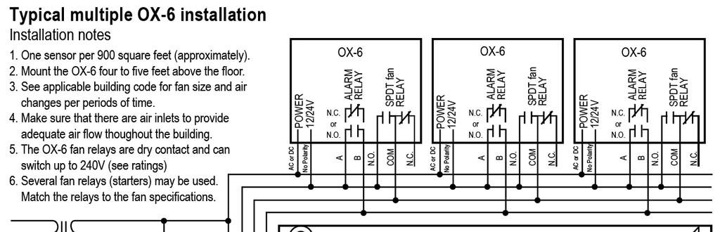
6 INSTALLATION AND OPERATING INSTRUCTIONS The following instructions are intended to serve as a guideline for the use of the Macurco OX-6 Oxygen Detector. It is not to be considered all-inclusive, nor is it intended to replace the policy and procedures for each facility. If you have any doubts about the applicability of the equipment to your situation, consult an industrial hygienist or call Technical Service at ! WARNING This detector helps monitor for the presence and concentration level of a certain specified airborne gas. Misuse may produce an inaccurate reading, which means that critical levels of the gas being monitored may be present and could result in overexposure and cause sickness or death. For proper use, see supervisor or User Instructions, or call Technical Service at Location An OX-6 is normally mounted at breathing level, about 5 feet (1.5 meters) above the floor on a wall or column in a central area where air movement is generally good. The unit, on average, can cover about 900 sq. ft. (84 sq. meters). The coverage depends on air movement within the room or facility. Extra detectors may be needed near any areas where people work or where the air is stagnant. Do NOT mount the OX-6 where the normal ambient temperature is below below 0 F or exceeds 125 F (below -18C or above 52C).! WARNING High voltage relay terminals (120/240 VAC) are located within this detector, presenting a hazard to service technicians. Only qualified technicians should open the detector case and service the internal circuits. Ensure power is removed from the detector relays prior to servicing the unit. Failure to do so may result in sickness or death. Installation 1. The OX-6 mounts on a 4 square (or 4x4) electrical box supplied by the contractor. Do not mount the OX-6 inside another box, unless it has good air flow through it. 2. Connect the OX-6 to Class 2 power supply only. It is suggested to use a separate transformer for powering the unit or units because of possible interference s from other devices on the same power supply. 3. Connect the OX-6 to the control cables with terminal plugs. When making connections, make sure the power is off. 4. There are two terminals for Power: 12 to 24 VAC or 12 to 32 VDC, with no polarity preference. 5. There are two terminals for the dry alarm relay contacts, again with no polarity preference. The alarm relay can switch up to 0.5 A 120 V, or 60 VA. The alarm relay is activated if gas reaches or exceeds the alarm settings. See OPERATION section of these User Instructions for details on relay settings. 6. The alarm relay can be configured to normally open (default) (N.O.) or normally closed (N.C.) and will activate if the gas concentration drops below alarm set point. It will deactivate once the gas concentration exceeds the alarm set point. Note that the disable setting will cause the alarm relay not to engage at all. 6

7 7. The dry contact, SPDT fan relay has three terminals. The common (COM.), normally open (N.O.) and the normally closed (N.C.) contact. The fan relay can switch up to 5.0 A up to 240 VAC. See OPERATION section of these User Instructions for details on relay settings. 8. The Fan Relay can be configured for latching or non-latching (default) when activated (when the oxygen concentration drops below fan relay set point). Once latched in, power will need to be interrupted or the TEST button pressed to un-latch the relay condition. 9. The Fan Relay will engage if the fan setting oxygen concentration drops below the set point for longer than the Fan Relay Delay time. Unless it is configured for latching, the fan relay will disengage once both of these conditions have been met: Oxygen concentration has exceeded fan setting Fan Relay Run time has been exceeded Note that the disable fan setting will cause the fan relay to not engage. The fan relay will engage in trouble fault condition (if the Trouble Fan Setting Option is set to On ) and will disengage once trouble fault condition is cleared. 10. The Current Loop is 4 ma at 0% v/v, 17.4 ma in clean air (20.9 v/v) and 20 ma at 25% v/v. Note: Increased levels of oxygen may dramatically increase the flammability of any combustible matter. If oxygen levels rise to 23.5% v/v the Fan Relay and Alarm Relay will be activated. This is a preset function and is not selectable. 7
8 8
9 9
 and finally go into normal operation.")
10 Power Up The OX-6 steps through an internal self-test cycle for the first 1 minute that it is powered. The unit will execute the test cycle any time power is dropped and reapplied (i.e. power failure). During the self-test cycle the unit will display the Firmware Version number and the gas type, then count down from 60 to 0 (if the display option is On ) and finally go into normal operation. The alarm relay will be activated for 10 seconds and the fan relay for 60 seconds during the power-up cycle unless the Power Up Test (PUt) option is OFF. The indicator light (LED) will flash green during the self-test cycle. At the end of the 1 minute cycle, the unit will take its first sample of the air and the indicator light will turn solid green. Operation 1. With the display function turned On, the OX-6 will show the current concentration of O2 % v/v or 20.9 in normal air. When the O2 concentration reaches the Fan Relay setting (20.5%, for example) the display will flash back and forth between FAn and With the display function turned OFF, the display does not show the gas concentration, but will show FAn as long as the fan relay is activated. 2. With the display function turned On and the O2 concentration reaching the Alarm Relay setting, (19.5%, for example) the display will flash back and forth between ALr and The buzzer will sound indicating Alarm if the buzzer is turned On. With the display function turned off the display does not show the O2 concentration, but will show ALr when the Alarm relay is activated. 3. With the 4-20 ma function turned On and the O2 concentration climbing the 4-20 ma signal will ramp up corresponding to the concentration (0-25% v/v). Default Configuration Factory Settings The default Power Up Test setting is ON The default Display setting is ON The default Buzzer setting is ON 10
11 The default Alarm Relay Setting is activation at 19.5% v/v The default Alarm Relay Configuration is Normally Open The default Fan Relay Setting is activation at 20.2% v/v The default Fan Relay Delay setting is 3 minutes The default Fan Relay Runtime setting is 0 minutes The default Fan Relay Latching condition is OFF The default Trouble Fan Setting condition is OFF The default 4-20mA Output setting is ON To change settings, remove the Philips screw on the front of the OX-6. Pull off the front cover of the unit. Selecting Default Configuration def To select the Default Configuration, in normal mode, push the Next button to get to Con or the Configuration menu. Then push the Enter button to enter the Con menu. The first selection is the def or Default setting. Push Enter. If it is already in Default configuration, there will be no action. If it is not already in Default configuration, no will be displayed. Push Next to change it to yes (flashing) then push Enter to confirm the change (solid) and push Enter again to return to def in the con menu. Push Next until End is displayed then push Enter to get back to normal operation. 11
12 Selecting Power Up Test Option PUt To select the Power Up Test Configuration, in normal mode, push the Next button to get to Con or the Configuration menu. Then push the Enter button to enter the Con menu. Then push the Next button to get to the second selection PUt or Power Up Test setting. Push Enter. If the test is On push Next to turn it OFF (flashing) then push Enter to confirm the change (solid) and push Enter again to return to PUt in the Con menu. Push Next until End is displayed then push Enter to get back to normal operation. Selecting Display Option dsp To select the Display Configuration, in normal mode, push the Next button to get to Con or the Configuration menu. Then push the Enter button to enter the Con menu. Then push the Next button to get to the third selection dsp or Display setting. Push Enter. If the display is On push Next to turn it OFF (flashing) then push Enter to confirm the change (solid) and push Enter again to return to dsp in the Con menu. Push Next until End is displayed then push Enter to get back to normal operation. Selecting Buzzer Option buz To select the Buzzer Configuration, in normal mode, push the Next button to get to Con or the Configuration menu. Then push the Enter button to enter the Con menu. The fourth selection is the buz or Buzzer setting. Push Next three times to get to buz then Enter. If the display is On push Next to turn it OFF (flashing) then push Enter to confirm the change (solid) and push Enter again to return to buz in the Con menu. Push Next until End is displayed then push Enter to get back to normal operation. Selecting Alarm Relay Setting ArS To select the Alarm Relay Setting, in normal mode, push the Next button to get to Con or the Configuration menu. Then push the Enter button to enter the Con menu. The fifth selection is the ArS or Alarm Relay Setting. Push Next four times to get to ArS then Enter. If the display is dis (disabled) push Next to change it to 18.5, 19, 19.5, 20 or 20.5% v/v (flashing) then push Enter to confirm the change (solid) and push Enter again to return to ArS in the Con menu. Push Next until End is displayed then push Enter to get back to normal operation. Selecting Alarm Relay Configuration Arc To select the Alarm Relay Configuration, in normal mode, push the Next button to get to Con or the Configuration menu. Then push the Enter button to enter the Con menu. The sixth selection is the Arc or Alarm Relay Configuration. Push Next five times to get to Arc then Enter. If the relay is no (normally open) push Next to turn it to nc (flashing) then push Enter to confirm the change (solid) and push Enter again to return to Arc in the Con menu. Push Next until End is displayed then push Enter to get back to normal operation. Selecting Fan Relay Settings FrS To select the Fan Relay setting, in normal mode, push the Next button to get to Con or the Configuration menu. Then push the Enter button to enter the Con menu. The seventh selection is the FrS or Fan Relay setting. Push Next six times to get to FrS then Enter. If the fan relay is dis (disabled) push Next to change it to 18, 18.1, 18.2, 18.3, 18.4, 18.5, 18.6, 18.7, 18.8, 18.9, 19, 19.1, 19.2, 19.3, 19.4, 19.5, 19.6, 19.7, 19.8, 19.9, 20, 20.1, 20.2, 20.3, 20.4 or 20.5% v/v (flashing) then push Enter to confirm the change (solid) and push Enter again to return to run in the Con menu. Push Next until End is displayed then push Enter to get back to normal operation. Selecting Fan Relay Delay Frd To select the Fan Relay Delay setting, in normal mode, push the Next button to get to Con or the Configuration menu. Then push the Enter button to enter the Con menu. The eighth selection is the Frd or Fan Relay Delay. Push Next seven times to get to Frd then Enter. If the delay is 0 (disabled) push Next to change it to 1, 3, 5, or 10 minutes (flashing) then push Enter to confirm the change 12
13 (solid) and push Enter again to return to Frd in the Con menu. Push Next until End is displayed then push Enter to get back to normal operation. Selecting Fan Relay Run Time Frr To select the Fan Minimum Runtime setting, in normal mode, push the Next button to get to Con or the Configuration menu. Then push the Enter button to enter the Con menu. The ninth selection is the Frr or Fan Minimum Run Time. Push Next eight times to get to Frr then Enter. If the runtime is OFF (disabled) push Next to change it to 3, 5, 10 or 15 minutes (flashing) then push Enter to confirm the change (solid) and push Enter again to return to Frr in the Con menu. Push Next until End is displayed then push Enter to get back to normal operation. Selecting Fan Relay Latching Option FrL To select the Fan Relay Latching Option, in normal mode, push the Next button to get to Con or the Configuration menu. Then push the Enter button to enter the Con menu. The tenth selection is the FrL or Fan Relay Latching Option. Push Next nine times to get to FrL then Enter. If latching is OFF push Next to turn it to On (flashing) then push Enter to confirm the change (solid) and push Enter again to return to FrL in the Con menu. Push Next until End is displayed then push Enter to get back to normal operation. Selecting Trouble Fan Setting Option tfs To select the Trouble Fan Setting Option, in normal mode, push the Next button to get to Con or the Configuration menu. Then push the Enter button to enter the Con menu. The eleventh selection is the tfs or Trouble Fan Setting Option. Push Next ten times to get to tfs then Enter. If Trouble Fan Setting is OFF push Next to turn it to On (flashing) then push Enter to confirm the change (solid) and push Enter again to return to tfs in the Con menu. Push Next until End is displayed then push Enter to get back to normal operation. Selecting 4-20mA Output Option 420 To select the 4-20mA Output Option, in normal mode, push the Next button to get to Con or the Configuration menu. Then push the Enter button to enter the Con menu. The twelfth selection is the 420 or 4-20mA Output Option. Push Next eleven times to get to 420 then Enter. If the 4-20mA is On push Next to turn it to OFF (flashing) then push Enter to confirm the change (solid) and push Enter again to return to 420 in the Con menu. Push Next until End is displayed then push Enter to get back to normal operation. Onboard Diagnostics The OX-6 monitors all critical functions of the unit through software diagnostics that continuously test and verify unit operations. If a problem is found, the unit will switch to a fail-safe/error mode or trouble condition. In this error mode, the Alarm relay will be activated, the 4-20 ma current loop will go to 24 ma, the unit will display the error code, the green status indicator LED light will flash and the buzzer will chirp intermittently. The Fan relay will also engage if the Trouble Fan Setting Option is set to On. This is a safety precaution. To clear this mode, simply turn off power to the unit for a few seconds, or push the ENTER/TEST switch (inside the unit). This will cause the unit to restart the 1 minute self-test cycle. The 4-20 ma signal can be used for troubleshooting: 0 ma is most likely a connection problem 4-20 ma is normal gas reading range (0-25% v/v) 24 ma indicates a Trouble condition 13
14 Error Codes t01 Sensor missing t02 Temperature compensation failure t04 EEPROM bad checksum t10 Bad EEPROM t20 Bad calibration t40 Factory calibration failure t80 Read ADC failure t100 Under range t200 Sensor warranty expired Note: For trouble codes over 080 the display will alternate between t_1 and t00 for t100 and between t_2 and t00 for t200. If the error mode repeats frequently, check for continuous power and proper voltage. If power is not the problem and a unit has repeating error conditions, it may need to be returned to Macurco for service, per these User Instructions. If the error mode indicates Sensor warranty expired see the Sensor Replacement section of these User Instructions. Sensor Poisons The gas sensor in the detector is designed with extreme sensitivity to the environment. As a result, the sensing function may be deteriorated if it is exposed to a direct spray from aerosols such as paints, silicone vapors, etc., or to a high density of corrosive gases (such as hydrogen sulfide, sulfur dioxide) for an extended period of time. MAINTENANCE The OX-6 requires periodic maintenance. The unit uses an electrochemical sensor with a 2-3 year life expectancy that can be tested, calibrated and replaced in the field. The OX-6 replacement sensor is available through your local representative or from Macurco. The detector s performance should be tested regularly by using gas as detailed in the Testing and Field Calibration sections. All other maintenance and repair of products manufactured by Macurco are to be performed at the appropriate Macurco manufacturing facility. Macurco does not sanction any third-party repair facilities. End-of-Warranty Signal Two years after the OX-6 is installed the sensor end-of-warranty signal will be activated indicating that the OX-6 sensor has reached the end of its warranty period. The end-of-warranty signal will cause an error code t200 Sensor warranty expired. See Error Codes section. In addition to the end-of-warranty signal the sensor itself has a tamper proof warranty expiration sticker dated 2 years from the unit manufacture date. See the Macurco Fixed Gas Detection Products Limited Warranty section. The end-of-warranty signal can be silenced for 48 hours by pressing the "ENTER/TEST" button or by temporarily dropping power to the unit. The end-of-warranty signal provides the user an opportunity to test and/or calibrate the sensor assuring that it is still performing within acceptable parameters though the sensor is nearing the end of its 2-3 year expected life. The silence function will continue to be available for 29 days after the OX-6 initiates the initial end-of-warranty signal. After this 29 day period the OX-6 can no longer be silenced and the sensor must be replaced or the sensor life reset. 14
15 Sensor Replacement 1. Remove power to the unit 2. Remove the Philips screw on the front of the OX-6. Pull the front cover of the unit off. 3. Remove the sensor by pulling it gently from the three pronged socket. 4. Power up the unit. The OX-6 steps through an internal self-test cycle for the first 1 minute that it is powered. During the self-test cycle the unit will display the Firmware Version number, then count down from 60 to 0 and finally go into normal operation. The indicator light (LED) will flash green during the self-test cycle. At the end of the 1 minute cycle, the unit will take its first sample of the air and the indicator light will turn solid green. 5. Let the new sensor stabilize for at least 20 minutes then refer to the FIELD CALIBRATION PROCEDURE section to calibrate the unit. 6. After the successful calibration is complete, reset the sensor life. Sensor Life Reset 1. Remove the Philips screw on the front of the OX-6. Pull the front cover of the unit off. 2. To reset the sensor life (rst), from normal or warm-up mode, press the Next button four times to get to SEn or Sensor Mode. 3. Then press the Enter button to get to rst - Reset Sensor Mode. 4. Press the Enter button again to see the sensor reset status. If the sensor life has already been reset, done don will be displayed. If it has not already been reset, no will be displayed. Push Next to change it to yes (flashing) then push Enter to confirm the change (solid) and push Enter again to return to rst in the SEn menu. Push Next until End is displayed then push Enter to get back to normal operation. Note: If the sensor is reset and not replaced it is necessary to test and/or calibrate the sensor to assure that it is still performing within acceptable specifications though the sensor is nearing the end of its 2-3 year expected life. There will be no other indication of sensor performance.! WARNING Do not disassemble unit or attempt to repair or modify any component of this instrument. This instrument contains no user serviceable parts, and substitution of components may adversely affect product performance and result in sickness or death. CAUTION Avoid the use of harsh cleaning materials, abrasives and other organic solvents. Such materials may permanently scratch the surfaces and damage the display window, labels, sensor or instrument housing. High voltage terminals ( VAC) are located within this detector, presenting a hazard to service technicians. Only qualified technicians should open the detector case and service the internal circuits. Ensure power is removed from the detector prior to cleaning the unit. Failure to do so may result in sickness or death. Cleaning Cleaning of the external surfaces is best carried out using a damp cloth with a mild detergent or soap. Use a vacuum cleaner with soft brush to remove dust or contamination under the cover. Do not blow out the sensor with compressed air. 15
16 TESTING! WARNING Using a certified gas with a concentration other than the one listed for this detector when conducting a calibration or calibration verification test (bump test) will produce inaccurate readings. This means that critical levels of the gas being monitored may be present and could result in overexposure and cause sickness or death. For proper use, see supervisor or User Instructions, or call Technical Service at General All OX-6 units are factory calibrated and 100% tested for proper operation. During normal operation the green status indicator LED light will be on steady, the fan & alarm relay will be in standby mode and the 4-20 ma output will be at 4mA (in clean air).the unit also performs a regular automatic self-test during normal operation. If the unit detects an improper voltage or inoperable component, it will default into Error mode. In this error mode, the Alarm relay will be activated, the 4-20 ma current loop will go to 24 ma, the unit will display the error code, the green status indicator LED light will flash and the buzzer will chirp intermittently. The Fan relay will also engage if the Trouble Fan Setting Option is set to On. Operation Test Check that the green OX-6 status indicator LED light is illuminated continuously. If not, do not proceed with the tests. If the unit is in error mode contact your local representative or Macurco technical service representative for information on resolving the problem. 1. Remove the single screw in the middle of the front cover of the OX Remove the front cover. 3. Observe the LED light on the front of the OX If the light is solid green proceed to step If the green status indicator LED light is off or flashing, refer to the General section above. 6. Locate the switch labeled ENTER/TEST on the left side of the printed circuit board. Press the Test switch once. 7. The OX-6 will step through a cycle test: a. The display progresses through the buz (buzzer Test) Art (alarm relay test), Frt (fan relay test) then 42t (4-20 ma output test). Make sure that the settings are On or not disabled dis. b. During the first 10 seconds of the test cycle, the display will show buz and set off the audible buzzer c. The alarm relay will be closed, so any devices connected to that relay will be tested. d. The Fan relay will be activated for the next 1 minute of the test, so if the fan circuits are wired in the normal manner, the fan should run. e. The 4-20mA output will then ramp up from 4 to 16 ma over the next 130 seconds of the test, so if the circuit is wired in the normal manner, the control panel or building automation system should respond. f. At the end of the test cycle, the light will turn green and be on steady (Normal Operation), the fan & alarm relay will be in standby mode and the 4-20 ma output will return to 17.4 ma (in clean air). 8. When testing is completed reassemble the unit or units. 16
17 Manual Operation Test This option gives the user the opportunity to manually initiate an individual test for each relay, the analog output and the sensor response to gas. From normal operation mode press the Next button 2 times to get to the Test Mode (tst). Press the Enter button once to get into the Test Menu. Press the Next button to scroll through the five test options and press Enter to initiate the selected test. Note that if the relay or 4 20 ma output has been disabled, the test selection will not be displayed in the test menu. buz Buzzer Test, 3 seconds Art - Alarm Relay Test, 10 seconds Frt - Fan Relay Test, 60 seconds 42t loop test, 130 seconds gts - Gas Test, 3 minutes (no output to the panel during the gas test) The display will flash during the test, or in the case of the gas test, the gas level will alternate with gts. Once the test is complete, the display will return to steady display. To exit the test menu, press the Next button until End is displayed, then press Enter to return to normal mode. Oxygen Gas Test! WARNING The following steps must be performed when conducting a calibration or calibration verification test (bump test) to ensure proper performance of the monitor. Failure to do so may adversely affect product performance and result in sickness or death. When performing a calibration or calibration verification test (bump test) only use certified calibration gas at the required concentration level. Do not calibrate with expired calibration gas. If the instrument cannot be calibrated, do not use until the reason can be determined and corrected. Do not cover or obstruct display or visual alarm cover. Ensure sensor inlets are unobstructed and free of debris General The OX-6 can be bump-tested with the OX-FTK with oxygen gas, regulator and test hood, available through your local representative or from Macurco. Contents of the FTK OX-FTK: (1) Gas Cylinder, 17.0% v/v oxygen gas in air Gas regulator with about two feet of plastic tubing Gas test hood FTK Information Several detectors can be tested with one FTK. The only limitation is the amount of gas in the cylinder and the flow of the regulator. The 34 liter cylinder for example with a 0.2LPM regulator has approximately 170 minutes of continuous calibration run time. Replacement cylinders are available. The gas cylinder should be replaced when the pressure gauge on the regulator shows 25-psi or less. Note: For optimum test results it is suggested that the unit be in clean air (green light on) and be in a low ambient air flow. 17
18 Gas Testing Testing the Fan Relay 1. Remove the Philips screw on the front of the OX-6. Remove the front cover. 2. Open the FTK. Connect the 17.0% v/v gas cylinder to the regulator. 3. Check the pressure gauge on the regulator. If you have 25-psi or less you will need to replace the gas canister. 4. Assemble regulator, hose and test hood and place the test hood over the gas sensor. Note: The time to activate the Fan relay depends on the delay setting. 5. Turn on the regulator to start the gas flow and wait with the gas applied continuously. 6. With the display function turned On, the OX-6 will show the current concentration of gas or 20.9 (% v/v) in clean air. When the gas concentration reaches the Fan Relay setting (20.2% v/v, for example) the display will flash back and forth between FAn and With the display function turned OFF, the display does not show the gas concentration, but will show FAn as long as the fan relay is activated. Note: If the Fan relay does not close within 2 minutes, there are five possibilities: a. Gas cylinder is empty, check the pressure gauge. Replace the gas cylinder if 25psi or less. b. Unit needs to be re-calibrated (go through recalibration and re-test). c. Detector has fan relay set to disable (OFF). Set fan relay to 20.2% v/v and repeat the test. d. Detector has fan relay delay set to 3 minutes or higher. Set fan relay to 0 minutes and repeat the test. e. Detector is in need of servicing (return unit to factory for servicing). 7. Remove the gas from the sensor. Proceed to Test the Alarm relay or replace the top cover. Fan relay test is complete. 18
19 Testing the Alarm Relay Note: The gas concentration to activate the Alarm relay depends on the setting. 1. Connect the 17.0% v/v cylinder of oxygen to the regulator. 2. Check the pressure gauge. If there is 25psi or less the cylinder should be replaced. 3. Place the test hood over the gas sensor. Turn on the regulator to start the gas flow. 4. The Fan relay should activate according to the settings. 5. With the display function turned On and the gas concentration reaching the Alarm Relay setting, (19.5% v/v, for example) the display will flash back and forth between ALr and The buzzer will sound indicating Alarm if the buzzer is turned On. With the display function turned off the display does not show the gas concentration, but will show ALr when the Alarm relay is activated. Note: If the Alarm relay fails to operate within 2 minutes, there are four possibilities: a. Gas cylinder is empty, check the pressure gauge. Replace the gas cylinder if 25-psi or less. b. Unit needs to be re-calibrated (go through recalibration and re-test). c. Detector has Alarm relay set to disable (OFF). Set Alarm relay to 19.5% v/v and repeat the test. d. Detector is in need of servicing (return unit to factory for servicing). 6. Remove the gas from the sensor after Test. Proceed to Test the 4-20mA output or replace the top cover. Alarm relay test is complete. Testing the 4-20mA current loop 1. Connect the 17.0% v/v cylinder of oxygen to the regulator. 2. Check the pressure gauge. If there is 25-psi or less the cylinder should be replaced. 3. Place the test hood from the regulator over the gas sensor. Turn on the regulator to start the gas flow. 4. The Fan relay should activate according to the settings. 5. The Alarm relay should activate according to the settings. 6. The 4-20 ma output should decrease from 17.4 ma in clean air (20.9% v/v) to 14.9 ma at 17.0% v/v. See 4-20 ma diagram on page 8. Note: If the 4-20mA output does not decrease within 2 minutes, there are four possibilities: a. Gas cylinder is empty, check the pressure gauge. Replace the gas cylinder if 25-psi or less. b. Unit needs to be re-calibrated (go through recalibration and re-test). c. Detector has 4-20 ma option set to OFF. Set 4-20mA option to On and repeat the test. d. Detector is in need of servicing (return unit to factory for servicing). 7. Remove the gas from the sensor. Re-assemble the OX-6 (make sure the LED is aligned with the front case hole) current loop test is complete. FIELD CALIBRATION PROCEDURE Note: For optimum calibration results the unit must be in clean air and be in a low ambient air flow. Calibrating the Sensor to Clean Air 19
 from normal mode, press the Next button three times to get to CAL or Calibration Mode. 3. Then press the Enter button to get to SPn - Calibration Span Mode.")
20 1. Remove the Philips screw on the front of the OX-6. Pull the front cover of the unit off. 2. To select Calibration Mode (CAL) from normal mode, press the Next button three times to get to CAL or Calibration Mode. 3. Then press the Enter button to get to SPn - Calibration Span Mode. The unit will display the current oxygen reading (% v/v) alternating with SPn (blinking) indicating calibration in progress (max 165 sec). 4. If the process is successful, the display will read 20.9 alternating with PAS (blinking) Calibration complete. 5. If the process was not successful the display will read the current oxygen reading (% v/v) alternating with FAL (Fail) (blinking) Calibration Failed. If this occurs, repeat steps 2 through 4. If the sensor fails to calibrate twice contact Technical Assistance: To return to Normal Mode press Enter and then press Next until 20.9 or the current reading is displayed, or the unit will simply time out to CAL then normal mode. 7. Re-assemble the OX-6 (make sure the LED is aligned with the front case hole). Calibration is complete. 8. See Calibration Flowchart on the inside of the housing. MACURCO FIXED GAS DETECTION PRODUCTS LIMITED WARRANTY Macurco warrants the OX-6 gas detector will be free from defective materials and workmanship for a period of two (2) years from date of manufacture (indicated on the inside cover of the OX-6), provided it is maintained and used in accordance with Macurco instructions and/or recommendations. If any component becomes defective during the warranty period, it will be replaced or repaired free of charge, if the unit is returned in accordance with the instructions below. This warranty does not apply to units that have been altered or had repair attempted, or that have been subjected to abuse, accidental or otherwise. The above warranty is in lieu of all other express warranties, obligations or liabilities. THE IMPLIED WARRANTIES OF MERCHANTABILITY AND FITNESS FOR PARTICULAR PURPOSE ARE LIMITED TO A PERIOD OF TWO (2) YEARS FROM THE PURCHASE DATE. Macurco shall not be liable for any incidental or consequential damages for breach of this or any other warranty, express or implied, arising out of or related to the use of said gas detector. Manufacturer or its agent s liability shall be limited to replacement or repair as set forth above. Buyer s sole and exclusive remedies are return of the goods and repayment of the price, or repair and replacement of non-conforming goods or parts. Manufactured by Aerionics, Inc. Sioux Falls, SD info@aerionicsinc.com Phone: Rev Aerionics All rights reserved. Macurco is a trademark of Aerionics, Inc. 20
Macurco Ammonia Detector, Controller and Transducer TX-6-AM User Instructions. Important: Keep these User Instructions for reference
 Macurco Ammonia Detector, Controller and Transducer TX-6-AM User Instructions Important: Keep these User Instructions for reference TABLE OF CONTENTS GENERAL SAFETY INFORMATION 3 Intended Use 3 List of
Macurco Carbon Monoxide Detector, Controller and Transducer CM-6 User Instructions. Important: Keep these User Instructions for reference
 Macurco Carbon Monoxide Detector, Controller and Transducer CM-6 User Instructions Important: Keep these User Instructions for reference TABLE OF CONTENTS GENERAL SAFETY INFORMATION 3 Intended Use 3 List
Macurco OX-12 Oxygen Detector, Controller and Transducer User Instructions. Important: Keep these User Instructions for reference
 Macurco OX-12 Oxygen Detector, Controller and Transducer User Instructions Important: Keep these User Instructions for reference 2 TABLE OF CONTENTS GENERAL SAFETY INFORMATION 4 Intended Use 4 List of
Macurco RD-6 Refrigerant Detector, Controller and Transducer User Instructions. Important: Keep these User Instructions for reference
 Macurco RD-6 Refrigerant Detector, Controller and Transducer User Instructions Important: Keep these User Instructions for reference TABLE OF CONTENTS GENERAL SAFETY INFORMATION 3 Intended Use 3 List of
Macurco Combustible Gas Detector, Controller and Transducer GD-6 User Instructions. Important: Keep these User Instructions for reference
 Macurco Combustible Gas Detector, Controller and Transducer GD-6 User Instructions Important: Keep these User Instructions for reference TABLE OF CONTENTS GENERAL SAFETY INFORMATION Intended Use List of
Macurco TX-12-AM Ammonia Detector, Controller and Transducer User Instructions. Important: Keep these User Instructions for reference
 Macurco TX-12-AM Ammonia Detector, Controller and Transducer User Instructions Important: Keep these User Instructions for reference TABLE OF CONTENTS GENERAL SAFETY INFORMATION 3 Intended Use 3 List of
3 Macurco Combustible Gas Detector, Controller and Transducer User Instructions
 3 Macurco Combustible Gas Detector, Controller and Transducer User Instructions GD-6 Important: Keep these User Instructions for reference. TABLE OF CONTENTS GENERAL SAFETY INFORMATION...2 Intended Use...2
Macurco HD-11 Hydrogen Gas Detector User Instructions. Important: Keep these User Instructions for reference
 Macurco HD-11 Hydrogen Gas Detector User Instructions Important: Keep these User Instructions for reference 2 TABLE OF CONTENTS GENERAL SAFETY INFORMATION 4 INTENDED USE 4 LIST OF WARNINGS AND CAUTIONS
Macurco HD-11 Hydrogen Gas Detector
 Macurco HD-11 Hydrogen Gas Detector User Instructions Important: Keep these User Instructions for reference TABLE OF CONTENTS GENERAL SAFETY INFORMATION 3 Intended Use 3 List of Warnings and Cautions 3
Macurco CM-21A Carbon Monoxide
 Macurco CM-21A Carbon Monoxide Detector and Controller User Instructions for 3M Macurco CM-21A - Low voltage, dual relay Carbon Monoxide (CO) detector and controller Important: Keep these User Instructions
Macurco Single-Gas XL Series Monitor, CM-1XL Carbon Monoxide (CO), HS-1XL Hydrogen Sulfide (H2S) User Instructions
, HS-1XL Hydrogen Sulfide (H2S) User Instructions") Macurco Single-Gas XL Series Monitor, CM-1XL Carbon Monoxide (CO), HS-1XL Hydrogen Sulfide (H2S) User Instructions Important: Keep these User Instructions for reference 2 TABLE OF CONTENTS GENERAL SAFETY
Macurco Single-Gas XL Series Monitor, CM-1XL Carbon Monoxide (CO), HS-1XL Hydrogen Sulfide (H2S) User Instructions Important: Keep these User Instructions for reference 2 TABLE OF CONTENTS GENERAL SAFETY
3 Macurco Carbon Monoxide Detector CM-16A
 3 Macurco Carbon Monoxide Detector CM-16A User Instructions for 3M Macurco Carbon Monoxide Detector (CO) CM-16A FOR MORE INFORMATION In United States, contact: Website: www.3m.com/occsafety Technical Assistance:
Macurco CM-E1 Carbon Monoxide Detector
 Macurco CM-E1 Carbon Monoxide Detector User Instructions Important: These User Instructions are to be provided to the homeowner/end user upon product installation. Each person installing or using this
MACURCO INC. CONTROLLERS & CARBON MONOXIDE DETECTORS SS103-3A, SS103-10A SS102H, SS102HC-1 INSTALLATION & OPERATING INSTRUCTIONS
 MACURCO INC. CONTROLLERS & CARBON MONOXIDE DETECTORS SS103-3A, SS103-10A SS102H, SS102HC-1 INSTALLATION & OPERATING INSTRUCTIONS WWW.MACURCO.COM NOTE: SUGGESTED WIRE SIZE VS LENGTH OF WIRE BETWEEN EACH
Macurco DVP-120 Detection and Ventilation Control Panel
 Macurco DVP-120 Detection and Ventilation Control Panel User Instructions IMPORTANT: Keep these User Instructions for reference. TABLE OF CONTENTS 1 Introduction 4 1.1 General Information 4 1.2 Features
Macurco DVP-120 / DVP-120M Detection and Ventilation Control Panel User Instructions
 Macurco DVP-120 / DVP-120M Detection and Ventilation Control Panel User Instructions IMPORTANT: Keep these User Instructions for reference. TABLE OF CONTENTS 1 Introduction 4 1.1 DVP-120 General Information
Beacon 800 Gas Monitor Operator s Manual
 Beacon 800 Gas Monitor Operator s Manual Part Number: 71-0037RK Revision: F Released: 4/18/17 www.rkiinstruments.com Product Warranty RKI Instruments, Inc. warrants gas alarm equipment sold by us to be
TECHNICAL INSTRUCTIONS
 Carbon Monoxide Detector Installation Instructions TECHNICAL INSTRUCTIONS Carbon Monoxide Detector Installation Instructions This document provides instructions for installing the Carbon Monoxide Detector
GasScanner 8C. Eight Channel Monitor. Operator s Manual. MINT-0281-XX Rev. A 01/29/08
 GasScanner 8C Eight Channel Monitor Operator s Manual MINT-0281-XX Rev. A 01/29/08 Product Warranty Matheson Tri-Gas, Inc., warrants gas alarm equipment sold by us to be free from defects in materials,
GAS DETECTION MANUFACTURED BY. Aerionics, Inc. Sioux Falls, SD Phone:
 CM-1 CO ppm MANUFACTURED BY Aerionics, Inc. Sioux Falls, SD Phone: 1-877-367-7891 Email: info@aerionicsinc.com www.macurco.com Detectors for use with Fire and Security Systems The Macurco CM-E1, GD-2B,
INSTALLATION. and INSTRUCTION MANUAL. for QUALITY AIR BREATHING SYSTEMS. Model ABM - 715
 INSTALLATION and INSTRUCTION MANUAL for QUALITY AIR BREATHING SYSTEMS Model ABM - 715 M A R T E C H S E R V I C E S C O M P A N Y P.O. Box 7079 OFFICE: 800-831-1525 Mazeppa, MN 55956 Fax : (507)843-4953
GG-NO2 NITROGEN DIOXIDE GAS SENSOR. Installation and Operation Manual
 GG-NO2 NITROGEN DIOXIDE GAS SENSOR Installation and Operation Manual 2 GG-NO2 Warning Use this product only in the manner described in this manual. If the equipment is used in a manner not specified by
1040 Gas Monitor INSTALLATION AND OPERATING INSTRUCTIONS AMC-1040 WITH INTEGRAL ELECTROCHEMICAL SENSOR
 1040 Gas Monitor INSTALLATION AND OPERATING INSTRUCTIONS AMC-1040 WITH INTEGRAL ELECTROCHEMICAL SENSOR IMPORTANT: Please read these installation and operating instructions completely and carefully before
INSTALLATION. and INSTRUCTION MANUAL. for QUALITY AIR BREATHING SYSTEMS. Model ABM - 700
 INSTALLATION and INSTRUCTION MANUAL for QUALITY AIR BREATHING SYSTEMS Model ABM - 700 M A R T E C H S E R V I C E S C O M P A N Y P.O. Box 7079 OFFICE: 800-831-1525 Mazeppa, MN 55956 Fax : (507)843-4953
GG-NH3 AMMONIA GAS SENSOR. Installation and Operation Manual
 GG-NH3 AMMONIA GAS SENSOR Installation and Operation Manual 2 GG-NH3 Warning Use this product only in the manner described in this manual. If the equipment is used in a manner not specified by Calibration
GASGUARD SO2 Sulfur Dioxide Sensor OPERATING & INSTALLATION MANUAL
 GASGUARD SO2 Sulfur Dioxide Sensor OPERATING & INSTALLATION MANUAL Operating and Installation Manual Warning Use this product only in the manner described in this manual. If the equipment is used in a
GAS DETECTION. Parking Garage Guide
 GAS DETECTION Parking Garage Guide Building owners and facility managers want to provide safe and effective parking garages while minimizing the energy costs associated with heating, ventilation and air
Nitrogen Dioxide (NO2) Single-Point Gas Detection System
 Single-Point Gas Detection System") Nitrogen Dioxide (NO) Single-Point Gas Detection System DESCRIPTION Wall-mounted gas monitor with built-in nitrogen dioxide (NO)/diesel fume gas sensor, accepts one analog remote device such as a secondary
Nitrogen Dioxide (NO) Single-Point Gas Detection System DESCRIPTION Wall-mounted gas monitor with built-in nitrogen dioxide (NO)/diesel fume gas sensor, accepts one analog remote device such as a secondary
GG-EM ENTRANCE MONITOR. Installation and Operation Manual
 GG-EM ENTRANCE MONITOR Installation and Operation Manual 2 GG-EM Warning Use this product only in the manner described in this manual. If the equipment is used in a manner not specified by Calibration
GG-H2S HYDROGEN SULFIDE GAS SENSOR. Installation and Operation Manual
 GG-H2S HYDROGEN SULFIDE GAS SENSOR Installation and Operation Manual 2 GG-H2S Warning Use this product only in the manner described in this manual. If the equipment is used in a manner not specified by
GASGUARDIAN Channel Controller OPERATING & INSTALLATION MANUAL
 GASGUARDIAN 2 3 2-Channel Controller OPERATING & INSTALLATION MANUAL GasGuardian 2 3 Operating and Installation Manual Table of Contents General description.... 3 Installation. 3 Locating the GasGuardian-2..
GG-2 2-CHANNEL GAS DETECTION CONTROL PANEL. Installation and Operation Manual
 GG-2 2-CHANNEL GAS DETECTION CONTROL PANEL Installation and Operation Manual 2 GG-2 Warning Use this product only in the manner described in this manual. If the equipment is used in a manner not specified
Warranty Registration
 WARRANT Y AND LIMITS OF LIABILIT Y Vulcain Inc. warrants to the original purchaser that its product, and the component parts thereof, will be free from defects in workmanship and materials for a period
GG-R REFRIGERANT SENSOR. Installation and Operation Manual
 GG-R REFRIGERANT SENSOR Installation and Operation Manual 2 GG-R Warning Use this product only in the manner described in this manual. If the equipment is used in a manner not specified by Calibration
GG-CO-EXP CARBON MONOXIDE SENSOR. Installation and Operation Manual
 GG-CO-EXP CARBON MONOXIDE SENSOR Installation and Operation Manual 2 GG-CO-EXP Warning Use this product only in the manner described in this manual. If the equipment is used in a manner not specified by
GASGUARD NH 3. Ammonia Sensor OPERATING & INSTALLATION MANUAL
 GASGUARD NH 3 Ammonia Sensor OPERATING & INSTALLATION MANUAL Operating and Installation Manual 2 Table of Contents GasGuard NH 3 Operating and Instruction Manual General description. 4 Installation.. 4
Oxygen (O2) Single-Point Gas Detection System
 Single-Point Gas Detection System") Oxygen (O) Single-Point Gas Detection System DESCRIPTION Wall-mounted gas monitor with built-in oxygen (O) sensor, accepts one analog remote device such as a secondary gas sensor, temperature or humidity
Oxygen (O) Single-Point Gas Detection System DESCRIPTION Wall-mounted gas monitor with built-in oxygen (O) sensor, accepts one analog remote device such as a secondary gas sensor, temperature or humidity
MGC Dock User s Manual
 Operator s Manual Contents Warnings Statements/Avertisseement... 3 READ FIRST BEFORE OPERATION... 3 Basic Operation... 4 Clip Dock Components... 4 LEDs... 4 Operation... 5 Turning the Clip Dock On and
SENSIT HXG-2d Combustible Gas Detector
 INSTRUCTION MANUAL SENSIT HXG-2d Combustible Gas Detector Read and understand instructions before use. 710183 UL 913 Intrinsically Safe for Use in Class I, Groups C and D, T3 Hazardous Locations For use
MAN AUTO IMPORTANT INSTRUCTIONS PLEASE READ THIS MANUAL BEFORE INSTALLING AND USING APPLIANCE
 Wall Heater Fan MODEL #: 2275 This fan is a CSA approved component compatible with these Williams wall heaters only: 1076512.9 2076512.9 3076512.9 1276512 1876512 3076512 1076511.9 2076511.9 IMPORTANT
Model LP USER S MANUAL AND INSTALLATION INSTRUCTIONS
 Atwood Mobile Products LLC 1120 North Main Street Elkhart, IN 46614-3203 USA & Canada 1-866-869-3118 Internet: http://www.atwoodmobile.com Model LP USER S MANUAL AND INSTALLATION INSTRUCTIONS TESTED TO
MGC Dock User s Manual
 User s Manual Contents Warnings Statements/Avertisseement... 3 READ FIRST BEFORE OPERATION... 3 Description... 4 Basic Operation... 5 Clip Dock Components... 5 LEDs... 5 User Operation... 6 Turning the
GASGUARD O 2. Oxygen Sensor OPERATING & INSTALLATION MANUAL
 GASGUARD O 2 Oxygen Sensor OPERATING & INSTALLATION MANUAL 2 Table of Contents General description. 4 Installation.. 4 Locating the sensor. 4 Installation guidelines 5 Wiring.. 6 Operation.. 7 Start-up...
Digital Refrigerant System Analyzer. MAXMIN Psi kpa Bar MPa C F R TIME P T UNITS
 Digital Refrigerant System Analyzer INSTRUCTION MANUAL ENGLISH LOW START PRS T-LOW SUPERHEAT MAXMIN kpa Bar MPa R TIME P T HIGH END PRS T-HIGH SUBCOOL VAC 1-800-547-5740 Fax: (503) 643-6322 www.ueitest.com
! "! # Please read these installation and operating instructions completely and carefully before starting.
 ! "! # $% Please read these installation and operating instructions completely and carefully before starting. File name:3009405d Revised,20/10/2008 Copyright, July 2004 The Armstrong Monitoring Corporation
RK/ RK Carbon Monoxide Detector Operator s Manual
 65-2496RK/65-2499RK Carbon Monoxide Detector Operator s Manual Part Number: 71-0156RK Revision: 0 Released: 2/16/11 www.rkiinstruments.com WARNING Read and understand this instruction manual before operating
SENSIT HXG-2d. SENSIT TECHNOLOGIES 851 Transport Drive Valparaiso, IN Phone: (219) Fax: (219)
 Fax: (219)") WARRANTY AND REPAIR POLICY Your SENSIT HXG-2d instrument is warranted to be free from defects in materials and workmanship for a period of two years after purchase (excluding sensor, calibration and batteries).
WARRANTY AND REPAIR POLICY Your SENSIT HXG-2d instrument is warranted to be free from defects in materials and workmanship for a period of two years after purchase (excluding sensor, calibration and batteries).
Installation Manual. Detector Bases: PAD100-IB, PAD100-RB & PAD100-SB
 - + - + - + 1. Description This document provides instructions for mounting and wiring the Detector Bases PAD100-, PAD100-RB and PAD100-SB. The following detectors are compatible with Detector Bases PAD100-,
GASGUARD H2S EXP. Hydrogen Sulfide Sensor OPERATING & INSTALLATION MANUAL
 GASGUARD H2S EXP Hydrogen Sulfide Sensor OPERATING & INSTALLATION MANUAL Operating and Installation Manual Warning Use this product only in the manner described in this manual. If the equipment is used
M3050 Detector Operator s Manual
 FABRICON SYSTEMS ALBERTA 2008 INC. Keeping you in Front M3050 Detector Operator s Manual Telephone: (403)652-2127 Mailing Address: Shipping Address: Fax: (403)652-3027 Box 5996 402 Ellis Crescent S.E Email:
Carbon Monoxide Monitor and Retrofit Carbon Monoxide Monitor Kit W-2808/37027
 Carbon Monoxide Monitor and Retrofit Carbon Monoxide Monitor Kit W-2808/37027 User Instructions (Keep these instructions for reference) 3M W-2808 Supplied Air Respirator SAR Retrofit CO Monitor Kit 1 TABLE
CO2 RESPONDER Portable Carbon Dioxide Detector QUICK REFERENCE GUIDE
 CO2 RESPONDER Portable Carbon Dioxide Detector QUICK REFERENCE GUIDE GasAlertMicro 5 IR from Refer to for more details. Manual provided on CD with unit at time of purchase 2 Table of Contents Getting Started.
GASGUARD Cl 2. Chlorine Sensor OPERATING & INSTALLATION MANUAL
 GASGUARD Cl 2 Chlorine Sensor OPERATING & INSTALLATION MANUAL Operating and Installation Manual 2 Table of Contents GasGuard Cl 2 Operating and Instruction Manual General description. 4 Installation..
RK-05 Carbon Monoxide Detector Operator s Manual
 65-2433RK-05 Carbon Monoxide Detector Operator s Manual Part Number: 71-0189RK Revision: 0 Released: 5/17/11 RKI Instruments, Inc. www.rkiinstruments.com WARNING Read and understand this instruction manual
GLD-30 Gas Leak Detector
 GLD-30 Gas Leak Detector Installation, Operation & Maintenance General: The Archer Instruments GLD-30 is an ambient air monitor, used to detect the presence of a target gas (or gases) and to alert operators
Document No
 CO Guardian LLC 1951 E. Airport Dr. Tucson, AZ 85706 CARBON MONOXIDE DETECTOR MODEL 452 INSTALLATION AND OPERATIONAL MANUAL Document No. 01-2510-02 MODEL 452 INSTALLATION AND OPERATIONAL MANUAL Page 1
CA5000 Liquid CO 2 Freezer Backup System
 CA5000 Liquid CO 2 Freezer Backup System OPERATING INSTRUCTIONS MANUAL HAMPSHIRE CONTROLS CORPORATION ONE GROVE STREET / P.O. BOX 516, DOVER, NEW HAMPSHIRE USA 03821 TEL. (603) 749-9424 FAX (603) 749-9433
Duct and Rough Service Carbon Monoxide Sensor
 Product Identification and Overview Duct and Rough Service Carbon Monoxide Sensor BAPI s Carbon Monoxide Sensor offers enhanced electrochemical sensing with outstanding accuracy at low concentrations.
OPERATING INSTRUCTIONS
 OPERATING INSTRUCTIONS SPECIALTY REFRIGERATED TRANSPORT CABINETS FOR SATELLITE LOCATIONS RBQ-96 Caution: Read the instructions before using the machine. CONGRATULATIONS......and thank you for purchasing
GASGUARD H 2-1% Hydrogen Sensor OPERATING & INSTALLATION MANUAL
 GASGUARD H 2-1% Hydrogen Sensor OPERATING & INSTALLATION MANUAL 2 Table of Contents GasGuard H 2-1% General description. 4 Installation.. 4 Locating the sensor. 4 Installation guidelines 5 Wiring.. 6 Operation..
NIR O P E R A T I N G I N S T R U C T I O N S RETROREFLECTIVE PHOTOEYE U L M O N I T O R E D DEVICE
 O P E R A T I N G I N S T R U C T I O N S NIR-50-325 RETROREFLECTIVE PHOTOEYE U L 3 2 5-2 0 1 8 M O N I T O R E D DEVICE 4564 Johnston Parkway, Cleveland, Ohio 44128 P. 800 426 9912 F. 216 518 9884 Sales
GG-NH3-2% AMMONIA GAS SENSOR. Installation and Operation Manual
 GG-NH3-2% AMMONIA GAS SENSOR Installation and Operation Manual 2 GG-NH3-2% Warning Use this product only in the manner described in this manual. If the equipment is used in a manner not specified by Calibration
PAD100-6DB & PAD100-4DB PAD100-PD
 Installation Manual Detector Bases: PAD100-6DB & PAD100-4DB PAD100-PD Photoelectric Smoke Detector (ANSI/UL 268 Listed) PAD100-PHD Photoelectric Smoke / Heat Detector Combination (ANSI/UL 268 and ANSI/UL
II 2 G. SENSIT HXG-2d. Ex ib IIB T3 IP20. Suitable for combustible gases such as Methane, Butane, Propane and Natural Gas MADE IN USA
 SENSIT HXG-2d Combustible Gas Detector INSTRUCTION MANUAL Read and understand Instructions before use. PENDING II 2 G Ex ib IIB T3 IP20 PENDING (USA) Class 1, Division 1, Groups C and D, T3 Suitable for
Sentry LIQUID LEVEL GAUGE MODEL 200 or 200C OWNER MANUAL REV 1.7 SEPT08 PAGE 1 OF 12
 PAGE 1 OF 12 TABLE OF CONTENTS PAGE 1. SAFETY PRECAUTIONS 1.1. Electrical shock 3 2. APPLICATION 3 3. INSTALLATION 3.1. Mount indoor alarm display 3.2. Mount the outdoor junction box 3.3. Install interconnecting
RK-02 Multi Point Detector Operator s Manual
 65-2485RK-02 Multi Point Detector Operator s Manual Part Number: 71-0237RK Revision: A Released: 11/26/14 RKI Instruments, Inc. www.rkiinstruments.com WARNING Read and understand this instruction manual
RK/ RK Oxygen Detector Operator s Manual
 65-2502RK/65-2510RK Oxygen Detector Operator s Manual Part Number: 71-0074RK Revision: A Released: 3/1/11 www.rkiinstruments.com WARNING Read and understand this instruction manual before operating detector.
NEUTRONICS MINI ID R-1234yf REFRIGERANT IDENTIFIER OPERATION MANUAL
 NEUTRONICS MINI ID R-1234yf REFRIGERANT IDENTIFIER OPERATION MANUAL 456 Creamery Way, Exton, PA 19341, USA Phone: 610.524.8800 Fax: 610.524.8807 Email: info@refrigerantid.com www.refrigerantid.com Page
GG-LEL2 COMBUSTIBLE GAS SENSOR. Installation and Operation Manual
 GG-LEL2 COMBUSTIBLE GAS SENSOR Installation and Operation Manual 2 GG-LEL2 Warning Use this product only in the manner described in this manual. If the equipment is used in a manner not specified by Calibration
OI-2400-DOCK Multi Gas Docking Station. Operation Manual trevision 2.2w
 OI-2400-DOCK Multi Gas Docking Station Operation Manual trevision 2.2w Table of Contents Introduction... 3 Warnings Statements/Avertisseement... 4 Basic Operation... 5 OI-2400-DOCK Components... 5 LEDs...
RK/ RK Oxygen Detector Operator s Manual
 65-2494RK/65-2497RK Oxygen Detector Operator s Manual Part Number: 71-0179RK Revision: 0 Released: 2/16/11 www.rkiinstruments.com WARNING Read and understand this instruction manual before operating detector.
AirGard 385 Fume Hood Monitor
 OWNER S MANUAL AirGard 385 Fume Hood Monitor A TSI Company AIRGARD 385 MONITOR SPECIFICATIONS Digital Display Display Units 3 digit, 7-segment liquid crystal display. Feet per minute () or meters per second
RK-05 Carbon Monoxide Transmitter Operator s Manual
 65-2432RK-05 Carbon Monoxide Transmitter Operator s Manual Part Number: 71-0113RK Revision: B Released: 11/26/14 www.rkiinstruments.com WARNING Read and understand this instruction manual before operating
User s Guide HHAQ-109. Portable Multi-gas Detector. Shop online at omega.com SM
 User s Guide Shop online at omega.com SM e-mail: info@omega.com For latest product manuals: www.omegamanual.info HHAQ-109 Portable Multi-gas Detector User Guide Thanks for our using our products. Before
THERMAX Efficiency Monitor
 INSTALLATION & OPERATION INSTRUCTIONS THERMAX Efficiency Monitor Oil & Gas Fired Heating Equipment Efficiency Monitoring Instrument Important Safety Instructions Read and safe these instructions before
Operation Manual. Rev. E GEM-MRI. Oxygen Sampling System.
 Operation Manual Rev. E2 2015.03 GEM-MRI Oxygen Sampling System www.critical-environment.com GEM-MRI - Operation Manual Rev. E2 2015.03 Table of Contents 1 POLICIES... 4 1.1 Important Note...4 1.2 Warranty
CMF, CMX & CMA series
 Features Electrochemical sensor element 4-20 ma or 2-10 Vdc output CMF- IP 44 protection CMX- IP 54 protection CMA- IP 65 protection Wide supply voltage range (18-28 Vdc) Overload and short cicuit protected
CT-7 Series Toxic Gas Transmitter Operator s Manual
 65-2341 CT-7 Series Toxic Gas Transmitter Operator s Manual Part Number: 71-0424 Revision: P1 Released: 6/8/17 RKI Instruments, Inc. www.rkiinstruments.com WARNING Read and understand this instruction
Beacon 200 Gas Monitor Operator s Manual. Part Number: RK Released: 6/6/08
 Beacon 200 Gas Monitor Operator s Manual Part Number: 71-2102RK Released: 6/6/08 Table of Contents Chapter 1: Introduction.................................................3 Overview.............................................................3
Two-Channel Gas Controller
 Two-Channel Gas Controller Specifications subject to change without notice. USA 09 Page of DESCRIPTION Highly configurable, UL 0 performance-tested and -certified, and wall-mounted gas monitor; continuously
RK Multi Point Detector Operator s Manual
 65-2480RK Multi Point Detector Operator s Manual Part Number: 71-0198RK Revision: C Released: 11/26/14 RKI Instruments, Inc. www.rkiinstruments.com WARNING Read and understand this instruction manual before
Single Gas Clip and SGC Plus User s Manual Rev 2.3
 Single Gas Clip and SGC Plus User s Manual Rev 2.3 READ BEFORE OPERATION Gas Clip Technologies (GCT) Single Gas Clip and SGC Plus detectors are personal safety devices designed to detect the presence of
SEC 2000 Millenium Infrared Gas Detector
 SEC 2000 Millenium Infrared Gas Detector Instruction and Operation Manual Sensor Electronics Corporation 5500 Lincoln Drive Minneapolis, Minnesota 55436 USA (952) 938-9486 Fax (952) 938-9617 Email: sales@sensorelectronic.com
Analog Room Pressure Monitor RPC Series
 Description The Room Pressure Monitor is used to measure differential pressure in the range of 0.125 to 1"wc or 30 to 250 Pa. It combines precision high sensitivity silicon sensing capabilities and the
Oxygen Monitor Operating Manual
 Oxygen Monitor Operating Manual Model: RAD-0002 Remote Oxygen Storage Safety System 1. Product Description Thank you for selecting the RAD-0002 Remote Oxygen Storage Safety System. This monitor is designed
Single Gas Clip and SGC Plus User s Manual Rev 2.1 READ FIRST BEFORE OPERATION WARNING STATEMENTS / AVERTISSEMENT Activating tthe detector for the
 Single Gas Clip and SGC Plus User s Manual Rev 2.1 READ FIRST BEFORE OPERATION Gas Clip Technologies (GCT) Single Gas Clip and SGC Plus detectors are personal safety devices designed to detect the presence
1022 R/T Remote Monitor
 1022 R/T Remote Monitor INSTRUCTIONS AMC-1022R/T WITH REMOTE SENSOR OR TRANSMITTER INSTALLATION AND OPERATING INSTRUCTIONS FOR THE AMC-1022R/T UNIT IMPORTANT: Please read these installation and operating
WARRANT Y AND LIMITS OF LIABILIT Y Vulcain Inc. warrants to the original purchaser that its product, and the component parts thereof, will be free fro
 A d e v i h c r D c o n e m u WARRANT Y AND LIMITS OF LIABILIT Y Vulcain Inc. warrants to the original purchaser that its product, and the component parts thereof, will be free from defects in workmanship
Controllers. Instruction Manual WARNING
 Controllers Instruction Manual WARNING THIS MANUAL MUST BE CAREFULLY READ BY ALL INDIVIDUALS WHO HAVE OR WILL HAVE THE RESPONSIBILITY FOR INSTALLING, USING OR SERVICING THIS PRODUCT. Like any piece of
Operation Manual. Rev. E GEM-II Self Contained Gas Detector.
 Operation Manual Rev. E 2014.10 GEM-II Self Contained Gas Detector www.critical-environment.com GEM-II - Operation Manual Rev. E 2014.10 Table of Contents 1 POLICIES... 5 1.1 Important Note...5 1.2 Warranty
QUICK REFERENCE GUIDE
 - 4GAS RESPONDER Confined Space Entry Portable Gas Detector QUICK REFERENCE GUIDE 4-GAS RESPONDER GasAlertMicro 5 from Refer to for more details. Manual provided on CD with unit at time of purchase 2 Table
RK Hydrogen Sulfide Transmitter Operator s Manual
 65-2331RK Hydrogen Sulfide Transmitter Operator s Manual Part Number: 71-0176RK Revision: B Released: 11/26/14 RKI Instruments, Inc. www.rkiinstruments.com WARNING Read and understand this instruction
SBS-H2 Hydrogen Gas Detector Kit
 SBS-H2 Hydrogen Gas Detector Kit For battery charging rooms and other areas where hydrogen gas may be present INSTALLATION, OPERATION & MAINTENANCE INSTRUCTIONS Protects Life, Property and Profits Electrical
Carbon Monoxide (CO) Detecting Ventilation Fan Controller Model COSTAR 24VC-e Single Relay
 Detecting Ventilation Fan Controller Model COSTAR 24VC-e Single Relay") Carbon Monoxide (CO) Detecting Ventilation Fan Controller Model COSTAR 24VC-e Single Relay Part No. 905-0000-09 Replacement Sensor Module is Part Number 905-0001-09 1. INTRODUCTION Your COSTAR 24VC-e carbon
Carbon Monoxide (CO) Detecting Ventilation Fan Controller Model COSTAR 24VC-e Single Relay Part No. 905-0000-09 Replacement Sensor Module is Part Number 905-0001-09 1. INTRODUCTION Your COSTAR 24VC-e carbon
Instruction Manual WARNING
 Controllers Instruction Manual WARNING THIS MANAUL MUST BE CAREFULLY READ BY ALL INDIVIDUALS WHO HAVE OR WILL HAVE THE RESPONSIBILITY FOR INSTALLING, USING OR SERVICING THIS PRODUCT. Like any piece of
IMR IX176 Portable Gas Detector User Manual
 IMR Portable Gas Detector User Manual Read this manual carefully before using this device. (727) 328-2818 / (800) RING-IMR Fax: (727) 328-2826 www.imrusa.com Ver. 1.0A4 CONTENTS SERVICE GUIDELINES... 3
Operation Manual. Rev. D GEM-II Self-Contained Gas Detector.
 Operation Manual Rev. D 2012.04 GEM-II Self-Contained Gas Detector www.critical-environment.com Rev. D 2012.04 GEM-II Operation Manual TABLE OF CONTENTS 1 POLICIES... 5 1.1 Important Note... 5 1.2 Warranty
User Manual. PolyGard CO LC-1112 V3. Electrochemical analog carbon monoxide transmitters serial no. EC-S 002. August 29, 2006
 PolyGard CO LC-1112 V3 Electrochemical analog carbon monoxide transmitters serial no. EC-S 002 User Manual August 29, 2006 January 04, 2016 Revision Specifications subject to change without notice. USA
Model 405 AIRGARD Fume Hood Monitor
 INSTALLATION AND MAINTENANCE INSTRUCTIONS Model 405 AIRGARD Fume Hood Monitor A TSI Company Model 405 AIRGARD Fume Hood Monitor Specifications Instrument Dimensions Instrument Weight Shipping Weight Green
This instruction manual explains the use of three models listed on the left.
 Semiconductor Manufacturing Gas Detector This instruction manual explains the use of three models listed on the left. Keep this Instruction Manual available for quick reference when needed. Read this Instruction