1. RETAINING WALL SELECTION PROCEDURE
|
|
|
- Leslie Anthony
- 5 years ago
- Views:
Transcription


1
.")
2 1. RETAINING WALL SELECTION PROCEDURE a. Select the appropriate design table(s) depending on whether or not there are fences located above the retaining wall. Go to Section 3.1 or 4.1 of this document for retaining walls without fences above and Section 3.2 or 4.2 for retaining walls with fences above (up to a maximum of 1.8m high fence). It is noted that for retaining walls with fences above, refer to both Section or for general fence zones and Section or for the end zones of a fence (i.e. within 7.2 metres from the end of a fence). b. Select the correct design table based on the backill/subgrade material to be used for the retaining wall. 5 Different subgrade/backill materials have been catered for, namely: Gravel; Medium Dense Sand (Medium grained); Medium Dense Silty Sand/Fine Sand/ Shales; Stiff Clay; or Soft Clay Note: We recommend for walls greater than 2m height, geotechnical advice be sought to verify the nature of the subgrade/backill materials to be adopted for the design. c. The subgrade is the material into which the post is to be embedded and the backill is the material which is placed and compacted behind the retaining wall. d. Determine the actual height of the wall based on on-site measurements/survey. Example: Step 1. Step 2. Step 3. Step 4. Step 5. Step 6. An earth retaining wall with a 1,800mm high fence: Go to Section for the general fence zones (away from the end of the fence). Select the correct backill/subgrade material: Gravel Actual wall height: 1,100mm Select the post spacing: 2,000mm (the maximum wall height for that spacing is 1,200mm which is greater than the required wall height). Select the minimum post embedment depth: 1,000mm. Repeat Steps 1 to 5 for the end zones of a fence by referring to Section e. Determine the maximum post spacing for the wall height by referring to the relevant table(s) from Step a). Choose the post spacing for which the maximum wall height is greater than the actual wall height determined in Step c). f. Determine the minimum post embedment depth based on the selected subgrade/backill type, wall height, and post spacing. Page 2

3 Typical wall coniguration (Figure 1) The general coniguration of the wall with drainage installed behind the wall should generally conform to the diagram above. 2. HARD SOUND IGNEOUS ROCK Embedment of retaining wall posts within rock are not permitted. Page 3
4 3 POST SPACING AND EMBEDMENT DEPTH DESIGN TABLES 3.1 EARTH RETAINING WALL WITHOUT FENCES ABOVE 100UC14.8 POSTS IN 400MM Ø POST HOLES Backill Material/ Subgrade Material Post Spacing (mm) Gravel Maximum Wall Height (mm) Minimum Post Embedment Depth (mm) 750 Medium Dense Sand 2250 (Medium Grained) Silty Sand 2200 Fine Sand Shales 1800 Stiff Clay Soft Clay EMBEDMENT DEPTH VARIATION TABLE % Reduction in Wall Height No Fence % Reduction in Embedment Depth With Fence - General Zones With Fence - End Zones 10% 9% 3% 1% 20% 18% 6% 2% 30% 27% 9% 2% 40% 36% 12% 3% 50% 45% 15% 4% Page 4
5 3.2 EARTH RETAINING WALLS WITH FENCES ABOVE (MAX 1800MM HEIGHT) GENERAL ZONES (AWAY FROM THE END OF A FENCE) 100UC14.8 POSTS IN 400MM Ø POSTS HOLES Backill Material/ Subgrade Material Post Spacing (mm) Gravel Maximum Wall Height (mm) 1750 Minimum Post Embedment Depth (mm) Medium Dense Sand 1850 (Medium Grained) 950 Silty Sand 1800 Fine Sand Shales Stiff Clay Soft Clay EMBEDMENT DEPTH VARIATION TABLE % Reduction in Wall Height No Fence % Reduction in Embedment Depth With Fence - General Zones With Fence - End Zones 10% 9% 3% 1% 20% 18% 6% 2% 30% 27% 9% 2% 40% 36% 12% 3% 50% 45% 15% 4% Page 5
6 3.3 EARTH RETAINING WALLS END ZONES (WITHIN 7.2M FROM THE END OF THE FENCE) EARTH RETAINING WALL 100UC14.8 POSTS IN 400MM Ø POST HOLES Backill Material/ Subgrade Material Post Spacing (mm) Gravel Maximum Wall Height (mm) Minimum Post Embedment Depth (mm) 300 Medium Dense Sand 1400 (Medium Grained) Silty Sand Fine Sand Shales Stiff Clay Soft Clay EMBEDMENT DEPTH VARIATION TABLE % Reduction in Wall Height No Fence % Reduction in Embedment Depth With Fence - General Zones With Fence - End Zones 10% 9% 3% 1% 20% 18% 6% 2% 30% 27% 9% 2% 40% 36% 12% 3% 50% 45% 15% 4% Page 6
7 4 POST SPACING AND EMBEDMENT DEPTH DESIGN TABLES 4.1 EARTH RETAINING WALL WITHOUT FENCES ABOVE 150UC23 POSTS IN 450MM Ø POST HOLES Backill Material/ Subgrade Material Post Spacing (mm) Gravel Medium Dense Sand (Medium Grained) Silty Sand Fine Sand Shales Stiff Clay Soft Clay EMBEDMENT DEPTH VARIATION TABLE Maximum Wall Height (mm) Minimum Post Embedment Depth (mm) % Reduction in Wall Height No Fence % Reduction in Embedment Depth With Fence - General Zones With Fence - End Zones 10% 9% 6% 3% 20% 18% 12% 7% 30% 25% 16% 10% 40% 33% 21% 14% 50% 41% 25% 17% Page 7
8 4.2 EARTH RETAINING WALLS WITH FENCES ABOVE (MAX 1800MM HEIGHT) GENERAL ZONES (AWAY FROM THE END OF A FENCE) 150UC23 POSTS IN 450MM Ø POST HOLES Backill Material/ Subgrade Material Post Spacing (mm) Gravel Medium Dense Sand (Medium Grained) Silty Sand Fine Sand Shales Stiff Clay Soft Clay EMBEDMENT DEPTH VARIATION TABLE Maximum Wall Height (mm) Minimum Post Embedment Depth (mm) 2250 % Reduction in Wall Height No Fence % Reduction in Embedment Depth With Fence - General Zones With Fence - End Zones 10% 9% 6% 3% 20% 18% 12% 7% 30% 25% 16% 10% 40% 33% 21% 14% 50% 41% 25% 17% Page 8
9 4.3 EARTH RETAINING WALLS END ZONES (WITHIN 7.2M FROM THE END OF THE FENCE) UC23 POSTS IN 450MM Ø POST HOLES Backill Material/ Subgrade Material Post Spacing (mm) Gravel Medium Dense Sand (Medium Grained) Silty Sand Fine Sand Shales Stiff Clay Soft Clay EMBEDMENT DEPTH VARIATION TABLE Maximum Wall Height (mm) Minimum Post Embedment Depth (mm) % Reduction in Wall Height No Fence % Reduction in Embedment Depth With Fence - General Zones With Fence - End Zones 10% 9% 6% 3% 20% 18% 12% 7% 30% 25% 16% 10% 40% 33% 21% 14% 50% 41% 25% 17% Page 9

10 4.4 NOTES ON TABLES EMBEDMENT DEPTHS Embedment depths for cantilever retaining walls is critical. A small reduction in embedment depth results in a signiicant increase in stress within the foundation material and increases the likelihood of a foundation failure. Accordingly embedment depths noted within this document are considered minimum values. The igures given in Tables 3.1, 3.2.1, 3.3.1, 4.1, and assume that the same soil type is used for both backill and subgrade embedment INSTALLATION NOTES Allow minimum 48 hours for concrete to set in post holes prior to installing sleepers. Ensure horizontal alignment and correct height spacing prior to inserting sleepers into posts. Use packing under bottom row of sleepers if required. Place geotextile to rear face of sleepers to prevent drainage material from lowing through the small gaps between the sleepers. Lay slotted rigid PVC pipe behind the sleepers connected to stormwater as detailed in Typical Wall Coniguration diagram (igure 1). 5. SOIL PARAMETERS The formulation of the cantilever retaining walls within this document have been undertaken based on the following soil parameters: Subgrade/ Backill Type Density (kn/m³) Angle of Internal Friction Cohesion (kpa) Gravel Sand Silty sand Stiff clay Soft clay The sizes and dimensions shown for the tables in Section 3 and 4 of this document have been based on a Type 3 structure classiication to AS This assumes that failure of this type of structure would only result in minimal damage and loss of access. For higher structure classiications, engineering advice should be obtained. The tables shown in Section 3 and 4 of this document assumes that the backill behind the retaining wall is placed in a manner which is consistent with Controlled Fill - Class 1 as per AS The levels of compaction required to achieve this would be 98% of standard dry density in maximum 200mm compacted layers at optimum moisture content +/- 2%. For retaining walls where it is intended to place and compact the backill consistent with a lower classiication, engineering advice should be obtained. 6. POST AND SLEEPER SIZES All steel posts shall be 100UC14.8 or 150UC23 Grade 300 unless noted otherwise (refer Table 3 and 4). The post holes into which these members are placed shall be of a minimum diameter of 400mm or 450mm with minimum 100mm concrete cover at base of hole (refer Table 3 and 4). Minimum concrete grade in post hole to be 25MPa at 28 days. The sleepers used within these retaining walls consist of precast concrete 75mm thick and 200mm high. Minimum concrete strengths shall be 40 MPa at 28 days. Each sleeper shall be reinforced with 2N12 reinforcing bars longitudinal, with minimum 30mm cover. Page 10

, engineering advice")
11 7. SURCHARGE LOADS The retaining walls speciied in this document have been designed based on a 2.5kPa surcharge load in accordance with AS For retaining walls where a higher surcharge loading is required or where the retaining wall is within the zone of inluence of other structures (refer to Figure 2), engineering advice should be obtained. Figure 2 Page 11

. If the subgrade slope is beyond this amount, engineering advice should be obtained. 10.")
12 8. RETAINING WALL POST BATTERING Retaining walls of a height greater than 1,000mm, shall be battered back from vertical in the following amounts: Backill/Subgrade type Gravel, sand, silty sand 20:1 Stiff clay, soft clay 15:1 9. SUBGRADE SLOPE Batter (Vertical:Horizontal) The information contained within Section 3 and 4 of this document has been based on a maximum subgrade slope from 600mm beyond the base of the wall, of 1 vertical to 6 horizontal away from the wall (Refer to Typical Wall Coniguration Figure 1). If the subgrade slope is beyond this amount, engineering advice should be obtained. 10. BACKFILL SLOPE The information on the tables has been based on a horizontal backill slope only. For backill slopes beyond this amount, engineering advice should be obtained. 11. WALL TERRACING Utilising two terraced cantilever walls of half height instead of a single wall of full height is permitted so long as the distance between the two terraced walls conforms to Figure 3. Figure 3 Page 12
13 12. ATTACHMENT OF PALING FENCES Paling fences can be installed adjacent to the top of the retaining wall. The associated tables within Section 3 and 4 of this document have considered the following maximum wind loading on the associated paling fences: Maximum Fence Height: 1.8m Wind Region B to AS/NZS Terrain Category 2 N2 Wind Rating Structure Importance Level 1 Design Life 50 years It is noted that the fences are subjected to two different wind pressures. The wind pressures within a horizontal distance of 7.2 metres from the end of a fence are double that for general zones of the fence. For areas where the wind loading is greater than that noted above, engineering advice should be obtained. 13. FURTHER ASSUMPTIONS The formulation of this document has been undertaken on the following additional assumptions: The retaining wall is not subject to vibrations The water table is, in all cases, below the underside of the cantilever posts The subgrade into which the posts are to be placed is in a undisturbed natural state during the construction of the retaining wall. 14. EXPOSURE CONDITION The 100UC14.8 and 150UC23 steel posts are protected from corrosion based on atmospheric category C in accordance with AS/NZS 2312:2002. The coating system used in this case consists of hot dipped galvanising designated as HDG600. Unless noted otherwise or where engineering advice has been sought, the retaining walls shown within this document are not permitted to be installed in the following locations: Within 1km of the coast; Within 1km of a large body of salt water. 15. RELEVANT STANDARDS FOR THIS TYPE OF WALL: AS Earth-retaining structures AS/NZS Structural design actions - Part 0: General principles AS/NZS Structural design actions - Part 2: Wind actions AS Concrete structures AS/NZS 2312: 2002 Guide to the protection of structural steel against atmospheric corrosion by the use of protective coatings These tables were compiled by David Beneke Consulting. The information is provided for guidance purposes only in the design of retaining walls. If in doubt about the interpretation of the tables or the nature of the soil combinations at the site please seek expert advice. Page 13
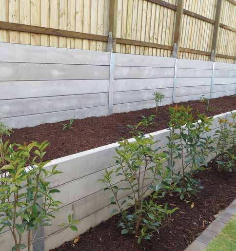
TECHNICAL. Design Guide. Retaining walls made easy with this beautiful solution EARTH RETAINING WALLS
 TECHNICAL Design Guide EARTH RETAINING WALLS Retaining walls made easy with this beautiful solution qro.com.au sales@qsolutionsco.com.au (07) 3881 0208 TDG-ERW-01 Sept 2017 1 RETAINING WALL SELECTION PROCEDURE
CHAPTER 4 EXPERIMENTAL WORK 4.1 GENERAL
 CHAPTER 4 EXPERIMENTAL WORK 4.1 GENERAL In the present chapter engineering properties of subgrade soils, moorum and aggregate used in the investigation are presented. The details of geotextiles and geogrids
THE OBJECTIVES OF ROUTINE ROAD CUTS AND FILLS
 Chapter 11 Slope Stabiliza bilization and Stability of Cuts and Fills THE OBJECTIVES OF ROUTINE ROAD CUTS AND FILLS are 1) to create space for the road template and driving surface; 2) to balance material
Installation Manual May 9/14 No revision
 815 NE 172 nd Avenue Vancouver, WA 98684 877-694-0141 Installation Manual May 9/14 No revision Installation steps include job planning, layout, excavating and preparing the soil subgrade, applying geotextiles
A. Install all temporary erosion control measures (in accordance with MNDOT General Conditions 2573) prior to site disturbance.
 prior to site disturbance.") The language provided in these specifications is meant to serve as a reminder and provide a generic example of the type of language that should be provided in final construction documents. This language
The language provided in these specifications is meant to serve as a reminder and provide a generic example of the type of language that should be provided in final construction documents. This language
Advanced Foundation Engineering. Sheet-Pile Walls
 Shahrood University of Technology Department of Geotechnical Engineering Advanced Foundation Engineering Sheet-Pile Walls Mohsen Keramati, Ph.D. Assistant Professor 1 Introduction Connected or semiconnected
APPENDIX E COMPACTION CHARACTERISTICS AND EQUIPMENT
 APPENDIX E COMPACTION CHARACTERISTICS AND EQUIPMENT When the Materials Division designs a pavement structure, there are a number of factors that influence it s outcome. Projected traffic counts, percentage
Indirect Design Comparison of the structural strength of the pipe (Three- Edge-Bearing Test) to the field supporting strength of a buried pipe.
 to the field supporting strength of a buried pipe.") 2 Indirect Design Comparison of the structural strength of the pipe (Three- Edge-Bearing Test) to the field supporting strength of a buried pipe. Direct Design The design of pipe in the installed condition.
2 Indirect Design Comparison of the structural strength of the pipe (Three- Edge-Bearing Test) to the field supporting strength of a buried pipe. Direct Design The design of pipe in the installed condition.
COMPARISON OF SHEAR STRENGTH PARAMETERS OF BLACK COTTON SOIL WITH EFFECT OF RELATIVE COMPACTION
 Vol-2 Issue-4 16 COMPARISON OF SHEAR STRENGTH PARAMETERS OF BLACK COTTON SOIL WITH EFFECT OF RELATIVE COMPACTION Prof. Usha k. Patel Assistant Professor, LDCE Prof. M. G. Vanza Associate Professor, LDCE
[Gupta* et al., 5(7): July, 2016] ISSN: IC Value: 3.00 Impact Factor: 4.116
![[Gupta* et al., 5(7): July, 2016] ISSN: IC Value: 3.00 Impact Factor: 4.116](/thumbs/90/102184431.jpg "[Gupta* et al., 5(7): July, 2016] ISSN: IC Value: 3.00 Impact Factor: 4.116") [Gupta* et al., 5(7): July, 6] ISSN: 77-9655 IC Value: 3. Impact Factor: 4.6 IJESRT INTERNATIONAL JOURNAL OF ENGINEERING SCIENCES & RESEARCH TECHNOLOGY EFFECT OF DENSITY AND MOISTURE ON THE SLOPE STABILITY
[Gupta* et al., 5(7): July, 6] ISSN: 77-9655 IC Value: 3. Impact Factor: 4.6 IJESRT INTERNATIONAL JOURNAL OF ENGINEERING SCIENCES & RESEARCH TECHNOLOGY EFFECT OF DENSITY AND MOISTURE ON THE SLOPE STABILITY
Road Soil. Curtis F. Berthelot Ph.D., P.Eng. Department of Civil Engineering. Road Soil Introduction
 Road Soil Characterization ti By: Curtis F. Berthelot Ph.D., P.Eng. Department of Civil Engineering Road Soil Introduction Roads are constructed of layered heterogeneous multiphase geo-materials that exhibit
AASHTO M Subsurface Drainage
 Subsurface Drainage Description: This specification is applicable to placing a geotextile against the soil to allow long-term passage of water into a subsurface drain system retaining the in -situ soil.
511 - RIP RAP - OPSS 511 ROCK PROTECTION - OPSS 511 GRAVEL SHEETING - OPSS 511 GEOTEXTILE - OPSS 511
 511 - - OPSS 511 ROCK PROTECTION - OPSS 511 GRAVEL SHEETING - OPSS 511 GEOTEXTILE - OPSS 511 511.1 GENERAL 511.1.1 Rip Rap 511.1.2 Rock Protection Excavation for placing Rip Rap, Rock Protection and Gravel
Low Gradient Velocity Control Short Term Steep Gradient [1] Channel Lining Medium-Long Term Outlet Control Soil Treatment Permanent
![Low Gradient Velocity Control Short Term Steep Gradient [1] Channel Lining Medium-Long Term Outlet Control Soil Treatment Permanent](/thumbs/77/74849271.jpg "Low Gradient Velocity Control Short Term Steep Gradient [1] Channel Lining Medium-Long Term Outlet Control Soil Treatment Permanent") Grass Linings DRAINAGE CONTROL TECHNIQUE Low Gradient Velocity Control Short Term Steep Gradient [1] Channel Lining Medium-Long Term Outlet Control Soil Treatment Permanent [1] May be used on short, steep
Grass Linings DRAINAGE CONTROL TECHNIQUE Low Gradient Velocity Control Short Term Steep Gradient [1] Channel Lining Medium-Long Term Outlet Control Soil Treatment Permanent [1] May be used on short, steep
Lightweight aggregates in Civil Engineering applications. Arnstein Watn Senior Scientist, SINTEF
 Lightweight aggregates in Civil Engineering applications Arnstein Watn Senior Scientist, SINTEF SINTEF Independent Multiscience Research Institute About 1800 employees Closely linked to the Universities
Gary Person, Foundation Engineer Geotechnical Engineering Section
 Minnesota Department of Transportation MEMO Mailstop 64 14 Gervais Avenue Maplewood, MN 9 DATE: November 3 rd, 214 TO: FROM: CONCUR: Bruce Johnson, Project Manager Metro Design Hossana Teklyes, Assist.
CHAPTER 8 SLOPE STABILITY ANALYSIS
 TM 5-818-1 / AFM 88-3. Chap. 7 CHAPTER 8 SLOPE STABILITY ANALYSIS 8-1. General. This chapter is concerned with characteristics and critical aspects of the stability of excavation slopes; methods of designing
The University of Iowa Department of Civil & Environmental Engineering SOIL MECHANICS 53:030 Final Examination 2 Hours, 200 points
 The University of Iowa epartment of Civil & Environmental Engineering SOIL MECHNICS 53:030 Final Examination 2 Hours, 200 points Fall 1998 Instructor: C.C. Swan Problem #1: (25 points) a. In a sentence
1 Introduction. 2 General Pile Analysis Features. 2.1 Pile Internal Forces and Displacements
 RSPile version 1.0 RSPile is a general pile analysis software for analyzing driven pile installation, axially loaded piles and laterally loaded piles. It is capable of computing the axial capacity for
Compaction. Compaction purposes and processes. Compaction as a construction process
 Compaction Compaction purposes and processes Specification and quality control Moisture condition value Compaction is a process that brings about an increase in soil density or unit weight, accompanied
Stormwater Control Plan: Small (Tier 1) Land Development Project
 Land Development Project") Stormwater Control Plan: Small (Tier 1) Land Development Project Project ID for Tracking (for City Staff only): The California Regional Water Quality Control Board for the Central Coast Region (Water Board)
Stormwater Control Plan: Small (Tier 1) Land Development Project Project ID for Tracking (for City Staff only): The California Regional Water Quality Control Board for the Central Coast Region (Water Board)
V. EROSION CONTROL. -Drainage swales separation -Under rip-rap protected -Under rip-rap unprotected
 V. EROSION CONTROL This section describes three different types of erosion control applications where geotextiles can be used in conjunction with some form of stone or other energy dissipating material
815 NE 172 nd Avenue Vancouver, WA Installation Manual
 815 NE 172 nd Avenue Vancouver, WA 98684 800-377-3877 www.xeripave.com info@xeripave.com Installation Manual Installation steps include job planning, layout, excavating and preparing the soil sub grade,
GEOSYNTHETICS ENGINEERING: IN THEORY AND PRACTICE
 GEOSYNTHETICS ENGINEERING: IN THEORY AND PRACTICE Prof. J. N. Mandal Department of Civil Engineering, IIT Bombay, Powai, Mumbai 400076, India. Tel.022-25767328 email: cejnm@civil.iitb.ac.in Module - 8
Load-Carrying Capacity of Stone Column Encased with Geotextile. Anil Kumar Sahu 1 and Ishan Shankar 2
 Load-Carrying Capacity of Stone Column Encased with Geotextile Anil Kumar Sahu 1 and Ishan Shankar 2 1 Professor, Department of Civil Engineering, Delhi Technological University, Delhi, India (sahuanilkr@yahoo.co.in)
Te c h S p e c 3. Edge Restraints for Interlocking Concrete Pavements
 Te c h S p e c 3 Edge Restraints for Interlocking Concrete Pavements Introduction Edge restraints are an essential component of interlocking concrete pavements. Restraints hold the pavers tightly together,
CONSTRUCTION SPECIFICATION FOR THE INSTALLATION OF INTERLOCKING CONCRETE PAVERS
 ONTARIO PROVINCIAL STANDARD SPECIFICATION METRIC OPSS.PROV 355 NOVEMBER 2014 CONSTRUCTION SPECIFICATION FOR THE INSTALLATION OF INTERLOCKING CONCRETE PAVERS TABLE OF CONTENTS 355.01 SCOPE 355.02 REFERENCES
Silva Cell 2 Installation Guidelines
 Silva Cell 2 Installation Guidelines Silva Cell 2 components Deck 1X post 3X post 2X post Base 1 Base (bottom piece) 2 Posts 1X 2X 3X (1x + 2X) 3 1X assembled 16.7 (424 mm) 4 2X assembled 30.9 (784 mm)
Full Scale Model Test of Soil Reinforcement on Soft Soil Deposition with Inclined Timber Pile
 Full Scale Model Test of Soil Reinforcement on Soft Soil Deposition with Inclined Timber Pile Suheriyatna 1, L. Samang 2, M. W. Tjaronge 3 and T. Harianto 4 1 Doctoral Student, Department of Civil Engineering,
PULLOUT CAPACITY OF HORIZONTAL AND INCLINED PLATE ANCHORS IN CLAYEY SOILS
 PULLOUT CAPACITY OF HORIZONTAL AND INCLINED PLATE ANCHORS IN CLAYEY SOILS BALESHWAR SINGH Associate Professor Department of Civil Engineering Indian Institute of Technology Guwahati Guwahati 78139, India
Construction of Interlocking Concrete Pavements
 Tech Spec 2 Construction of Interlocking Concrete Pavements Purpose This technical bulletin gives construction guidelines to design professionals and contractors of interlocking concrete pavements. The
PILE FOUNDATIONS CONTENTS: 1.0 Introduction. 1.1 Choice of pile type Driven (displacement) piles Bored (replacement) piles. 2.
 piles Bored (replacement) piles. 2.") PILE FOUNDATIONS CONTENTS: 1.0 Introduction 1.1 Choice of pile type 1.1.1 Driven (displacement) piles 1.1.2 Bored (replacement) piles 2.0 Analysis 2.0.1 Driving formulae 2.0.2 Soil mechanics 2.1 Piles
PILE FOUNDATIONS CONTENTS: 1.0 Introduction 1.1 Choice of pile type 1.1.1 Driven (displacement) piles 1.1.2 Bored (replacement) piles 2.0 Analysis 2.0.1 Driving formulae 2.0.2 Soil mechanics 2.1 Piles
Bearing Capacity Theory. Bearing Capacity
 Bearing Capacity Theory Bearing Capacity 1 Bearing Capacity Failure a) General Shear Failure Most common type of shear failure; occurs in strong soils and rocks b) Local Shear Failure Intermediate between
SUITABILITY OF GEOGRID REINFORCED - RUBBER WASTE IN PAVEMENTS
 Abstract S. Thenmozhi et. al. / International Journal of Engineering Science and Technology SUITABILITY OF GEOGRID REINFORCED - RUBBER WASTE IN PAVEMENTS S. THENMOZHI 1 Research Scholar, Department of
Slope stability assessment
 Engineering manual No. 25 Updated: 03/2018 Slope stability assessment Program: FEM File: Demo_manual_25.gmk The objective of this manual is to analyse the slope stability degree (factor of safety) using
ABBREVIATIONS. Dwg LID of 1. Abbreviations
 ABBREVIATIONS DIA DIAMETER EL ELEVATION FT2 SQUARE FOOT GAL/MIN GALLONS PER MINUTE H HORIZONTAL HDPE HIGH DENSITY POLYETHYLENE HMAC HOT MIX ASPHALT CONCRETE IE INVERT ELEVATION MAX MAXIMUM NO. NUMBER ODEQ
CONSTRUCTION SPECIFICATION FOR RIP RAP, ROCK PROTECTION AND GRAVEL SHEETING
 ONTARIO PROVINCIAL STANDARD SPECIFICATION METRIC OPSS 511 FEBRUARY 1990 CONSTRUCTION SPECIFICATION FOR RIP RAP, ROCK PROTECTION AND GRAVEL SHEETING 511.01 SCOPE 511.02 REFERENCES 511.03 DEFINITIONS 511.04
Comprehensive Material Characterizations for a Pavement Embankment Installed with Wicking Fabric
 Comprehensive Material Characterizations for a Pavement Embankment Installed with Wicking Fabric Chuang Lin Ph.D. Student Xiong Zhang Associate Professor University of Alaska Fairbanks Jie Han Professor
EAT 212 SOIL MECHANICS
 EAT 212 SOIL MECHANICS Chapter 4: SHEAR STRENGTH OF SOIL PREPARED BY SHAMILAH ANUDAI@ANUAR CONTENT Shear failure in soil Drained and Undrained condition Mohr-coulomb failure Shear strength of saturated
Pullout of Geosynthetic Reinforcement with In-plane Drainage Capability. J.G. Zornberg 1 and Y. Kang 2
 Zornberg, J.G., Kang, Y. (2005). Pullout of Geosynthetic Reinforcement with In-plane Drainage Capability. Geosynthetics Research and Development in Progress, Eighteenth Geosynthetic Research Institute
APPENDIX D. Slope Stability Analysis Results for Soil and Overburden Storage Mounds
 Geotechnical Assessment Report APPENDIX D Slope Stability Analysis Results for Soil and Overburden Storage Mounds DABGeot/09059GA/Final Geotechnical Assessment Report STABILITY OF SOIL AND OVERBURDEN STORAGE
South Fraser Perimeter Road (SFPR)
") MSE WALLS & SLOPES PROJECT PROFILE South Fraser Perimeter Road (SFPR) Nilex provides multiple solutions for the new four-lane highway along Vancouver s Fraser River. LOCATION: Delta and Surrey, British
MSE WALLS & SLOPES PROJECT PROFILE South Fraser Perimeter Road (SFPR) Nilex provides multiple solutions for the new four-lane highway along Vancouver s Fraser River. LOCATION: Delta and Surrey, British
III.DRAINAGE. This section describes the use of geotextiles in underdrains for two different field conditions:
 III.DRAINAGE This section describes the use of geotextiles in underdrains for two different field conditions: Protected (or light duty installations) and, Unprotected (for heavy duty installations). Both
Assessment of Geotextile Reinforced Embankment on Soft Clay Soil
 Assessment of Geotextile Reinforced Embankment on Soft Clay Soil M. Siavoshnia*, F. Kalantari and A. Shakiba Corresponding author: Civil Engineering Faculty, Neyaiesh Complex, Tehran Central Branch, Islamic
SOIL ENGINEERING (EENV 4300)
") SOIL ENGINEERING (EENV 4300) Chapter 5 Classification of Soil Why Classification? Classification systems provide a common language to concisely express the general characteristics of soils, which are infinitely
SOIL ENGINEERING (EENV 4300) Chapter 5 Classification of Soil Why Classification? Classification systems provide a common language to concisely express the general characteristics of soils, which are infinitely
PHYSICAL CHAtlACTERISTICS REPORT FOR THE PROPOSED SAND AND GRAVEL SITE AT MANOR FARM, UFFINGTON
 PHYSICAL CHAtlACTERISTICS REPORT FOR THE PROPOSED SAND AND GRAVEL SITE AT MANOR FARM, UFFINGTON Introduction Following the" request for detailed information on the physical characteristics of soil at Manor
Analysis of Pullout Resistance of Soil-Nailing in Lateritic Soil
 Analysis of Pullout Resistance of Soil-Nailing in Lateritic Soil B,L.A. Isaka 1, B.C. Madushanka 1 and N.H. Priyankara 1 1 Department of Civil and Environmental Engineering Faculty of Engineering University
EFFECT OF COMPACTION ON THE UNSATURATED SHEAR STRENGTH OF A COMPACTED TILL
 EFFECT OF COMPACTION ON THE UNSATURATED SHEAR STRENGTH OF A COMPACTED TILL Vanapalli, S.K., Pufahl, D.E., and Fredlund, D.G. (University of Saskatchewan, Saskatoon, SK., Canada, S7N 5A9) Abstract An experimental
SOIL FOUNDATION IMPROVEMENT WITH TIRE-USED TO REDUCE SETTLEMENT OF SHALLOW FOUNDATION EMBEDDED ON SATURATED DEPOK CLAY
 POLITEKNOLOGI VOL.13 NO.1 JANUARI 2014 SOIL FOUNDATION IMPROVEMENT WITH TIRE-USED TO REDUCE SETTLEMENT OF SHALLOW FOUNDATION EMBEDDED ON SATURATED DEPOK CLAY ABSTRACT PUTERA AGUNG M.A 1, SONY P 2, IMAM
Userguide Pole Embedment Calculator (PEC) Vsn
 Vsn") Userguide Pole Embedment Calculator (PEC) Vsn. 1.974 The Pole Embedment Calculator is a Microsoft Excel spreadsheet developed to assist designers to determine pole butt embedment depth given a variety
Userguide Pole Embedment Calculator (PEC) Vsn. 1.974 The Pole Embedment Calculator is a Microsoft Excel spreadsheet developed to assist designers to determine pole butt embedment depth given a variety
Field tests on the lateral capacity of poles embedded in Auckland residual clay
 Proc. 18 th NZGS Geotechnical Symposium on Soil-Structure Interaction. Ed. CY Chin, Auckland Field tests on the lateral capacity of poles embedded in Auckland residual clay Peter Rodgers Mercury Bay Civil
A Study on Stabilization of Subgrade Soil Using Natural Fibers (Coir and Jute)
") A Study on Stabilization of Subgrade Soil Using Natural Fibers (Coir and Jute) M. Mohan 1, L. Manjesh Research Scholar, Department of Civil Engineering, UVCE, Bangalore University, Bengaluru, Karnataka,
A Study on Stabilization of Subgrade Soil Using Natural Fibers (Coir and Jute) M. Mohan 1, L. Manjesh Research Scholar, Department of Civil Engineering, UVCE, Bangalore University, Bengaluru, Karnataka,
APPLICATIONS IN FILTRATION AND DRAINAGE & EROSION CONTROL
 Lecture 36 APPLICATIONS IN FILTRATION AND DRAINAGE & EROSION CONTROL Prof. G L Sivakumar Babu Department of Civil Engineering Indian Institute of Science Bangalore 560012 Geotextile filter requirements:
Up By Roots Healthy Soils and Trees in the Built Environment
 Up By Roots Healthy Soils and Trees in the Built Environment 2009 ASLA Honor Award James Urban, FASLA, ISA Urban Tree + Soils Annapolis, Maryland Practical Applications Preserving, repairing, and replacing
Paper ID: GE-007. Shear Strength Characteristics of Fiber Reinforced Clay Soil. M. R. Islam 1*, M.A. Hossen 2, M. A.Alam 2, and M. K.
 Paper ID: GE-7 International Conference on Recent Innovation in Civil Engineering for Sustainable Development (IICSD-2) Department of Civil Engineering DUET - Gazipur, Bangladesh 48 Shear Strength Characteristics
GEOSYNTHETICS ENGINEERING: IN THEORY AND PRACTICE
 GEOSYNTHETICS ENGINEERING: IN THEORY AND PRACTICE Prof. J. N. Mandal Department of civil engineering, IIT Bombay, Powai, Mumbai 400076, India. Tel.022-25767328 email: cejnm@civil.iitb.ac.in Module - 7
Dam Construction by Stages
 Dam Construction by Stages 1 Introduction This simple example demonstrates the simulation of staged embankment construction on soft ground. The primary objective of this example is to demonstrate the use
GEOTEXTILE DEFORMATION ANALYSIS OF GEOSYNTHETIC CLAY LINERS WITH FEM
 Geotextile deformation analysis of Geosynthetic Clay Liners under high hydraulic heads with Finite Element Method VII International Conference on Textile Composites and Inflatable Structures STRUCTURAL
CAPRICORN MUNICIPAL DEVELOPMENT GUIDELINES
 CAPRICORN MUNICIPAL DEVELOPMENT GUIDELINES PAVEMENT DESIGN D2 DESIGN GUIDELINES CAPRICORN MUNICIPAL DEVELOPMENT GUIDELINES D2 ISSUE: NO:3 September 2014 TABLE OF CONTENTS CLAUSE CONTENTS PAGE GENERAL...
geotextiles bidim Nonwoven polyester geotextile Made in Australia Designed for performance RECYCLED
 geotextiles bidim Nonwoven polyester geotextile Made in Australia Designed for performance RECYCLED INTRODUCTION The use of geotextiles in construction projects around the world has grown substantially
geotextiles bidim Nonwoven polyester geotextile Made in Australia Designed for performance RECYCLED Quality ISO 9001
 geotextiles bidim Nonwoven polyester geotextile Made in Australia Designed for performance Quality ISO 9001 RECYCLED INTRODUCTION The use of geotextiles in construction projects around the world has grown
GEOSYNTHETICS ENGINEERING: IN THEORY AND PRACTICE
 GEOSYNTHETICS ENGINEERING: IN THEORY AND PRACTICE Prof. J. N. Mandal Department of Civil Engineering, IIT Bombay, Powai, Mumbai 400076, India. Tel.022-25767328 email: cejnm@civil.iitb.ac.in Module - 2
A. Install all temporary erosion control measures (in accordance with MNDOT General Conditions 2573) prior to site disturbance.
 prior to site disturbance.") The language provided in these specifications is meant to serve as a reminder and provide a generic example of the type of language that should be provided in final construction documents. This language
The language provided in these specifications is meant to serve as a reminder and provide a generic example of the type of language that should be provided in final construction documents. This language
SOIL STABILIZATION USING NATURAL FIBER COIR
 SOIL STABILIZATION USING NATURAL FIBER COIR Pooja Upadhyay 1, Yatendra Singh 2 1M.Tech student, Department of Civil Engineering, IEC Group of Institutions, U.P, India 2Assistant Professor, Department of
GUIDELINE SPECIFICATIONS FOR SOIL MEDIA IN BIORETENTION SYSTEMS
 GUIDELINE SPECIFICATIONS FOR SOIL MEDIA IN BIORETENTION SYSTEMS The following guideline specifications for soil media in bioretention systems have been prepared on behalf of the Facility for Advancing
EFFECT OF BOLT CONNECTION OF SQUARE-SHAPED GEOCELL MODEL ON PULLOUT TEST RESULTS
 EFFECT OF BOLT CONNECTION OF SQUARE-SHAPED GEOCELL MODEL ON PULLOUT TEST RESULTS Zelong XU 1, Takashi KIYOTA 2, Sam Ronald OLOYA 3, Christian HAUSSNER 3 1 Ph. D. student, Institute of Industrial Science,
SWANA/A&WMA s. Third Annual Landfill Operator s Training Geosynthetics in Landfills. February 13, 2013
 SWANA/A&WMA s Third Annual Landfill Operator s Training Geosynthetics in Landfills February 13, 2013 Geosynthetics Products Applications Current Lining Requirements Tips 2 Geosynthetics polymeric products
DEPTH OF EMBEDMENT OF A SHEET PILE WALL
 IJRET: International Journal of Research in Engineering and Technology eissn: 319-1163 pissn: 31-738 DEPT OF EMBEDMENT OF A SEET PILE WALL M U Jagadeesha M.E.,M.I.E.,M.I.S.T.E, Lecturer, Jimma Institute
Rapid Drawdown with Multi-Stage
 1 Introduction Rapid Drawdown with Multi-Stage Stability analysis during rapid drawdown is an important consideration in the design of embankment dams. During rapid drawdown, the stabilizing effect of
6.2 Flow-Through Planter
 SAN MATEO COUNTYWIDE WATER POLLUTION PREVENTION PROGRAM 6.2 Flow-Through Planter Figure 6-8: At-grade flow-through planter. Source: City of Emeryville Best uses Treating roof runoff Next to buildings Dense
Mechanical Behavior of Soil Geotextile Composites: Effect of Soil Type
 Mechanical Behavior of Geotextile Composites: Effect of Type A.I. Droudakis and I.N. Markou Department of Civil Engineering, Democritus University of Thrace, Greece 12 Vas. Sofias str., GR-671 Xanthi,
 CI/SfB January 2015 (47) t6 Uniclass L524
 BAUER Soil Improvement
 BAUER Soil Improvement a fast and economic solution 2 3 In the 1960s Bauer started performing ground improvement. The first vibrator for vibrocompaction was created in 1962 under the supervision of Dr.-Ing.
THE ULTIMATE SKIN RESISTANCE OF CONCRETE PILE IN PARTIALLY SATURATED COHESIVE SOIL BY MODIFIED Β METHOD
 International Journal of Civil Engineering and Technology (IJCIET) Volume 9, Issue 10, October 2018, pp. 1882 1891, Article ID: IJCIET_09_10_187 Available online at http://www.iaeme.com/ijciet/issues.asp?jtype=ijciet&vtype=9&itype=10
Analyzing the Bioretention Construction Sequence
 Analyzing the Bioretention Construction Sequence Avoiding future problems through careful installation procedures, construction inspection and first year maintenance 20 Steps to Better Bioretention Step
SUBGRADE IMPROVEMENT OF CLAYEY SOIL WITH THE USE OF GEOTEXTILES
 SUBGRADE IMPROVEMENT OF CLAYEY SOIL WITH THE USE OF GEOTEXTILES 1 Soma Prashanth Kumar, 2 Mohammed Asif T L, 3 Mane S R Rohith 1 Assistant Professor, Department of Civil Engineering, JBIET, Moinabad, (India)
The following general requirements will be met for all planter box installations:
 Greenville County Technical Specification for: WQ-25 PLANTER BOX 1.0 Planter Box 1.1 Description Planter boxes are designed to capture and temporarily store stormwater runoff. Planter Boxes are intended
MARQUETTE UNIVERSITY DEPARTMENT OF CIVIL AND ENVIRONMENTAL ENGINEERING LAB REPORT FORMAT
 MARQUETTE UNIVERSITY DEPARTMENT OF CIVIL AND ENVIRONMENTAL ENGINEERING LAB REPORT FORMAT a. All reports must be typed and include the following sections in the order specified: Title Page Introduction
COHESIONLESS SOIL PROPERTIES IMPROVEMENT USING BENTONITE
 COHESIONLESS SOIL PROPERTIES IMPROVEMENT USING BENTONITE Khalida A. Daud Department of Architectural Engineering, Al-Nahrain University, Baghdad, Iraq E-Mail: khalida_dwd@yahoo.com ABSTRACT Construction
B511 - RIP-RAP, ROCK PROTECTION AND GRANULAR SHEETING - OPSS 511
 B511 - - OPSS 511 511.1 GENERAL 511.1.1 Rip-Rap Excavation for placing rip-rap, rock protection, and granular sheeting is part of each individual tender item. Rip-rap is a special application of rock protection.
Stress-Strain and Strength Behavior of Undrained Organic Soil in Kupondol, Kathmandu
 TUTA/IOE/PCU Journal of the Institute of Engineering, Vol. 8, No. 1, pp. 113 118 TUTA/IOE/PCU All rights reserved. Printed in Nepal Fax: 977-1-5525830 Stress-Strain and Strength Behavior of Undrained Organic
9 Steps to a Lasting Paver Installation
 9 Steps to a Lasting Paver Installation A whitepaper listing the time-proven paver installation process for Connecticut and Southern New England By Tom Bahler Although this whitepaper is fairly long and
SITE AND PROJECT DESCRIPTION
 51331 W. Pontiac Trail, Wixom, MI 48393 248.486.5 Main 248.486.5050 Fax February 11, 2015 Ms. Amy Kuras, Landscape Architect City of Ann Arbor Parks and Recreation Services 301 E. Huron Street Ann Arbor,
HYDRAULIC DESIGN involves several basic
 Chapter 6 Tools for Hydr draulic and Road Design HYDRAULIC DESIGN involves several basic concepts that must be considered to build successful projects with a minimum risk of failure (Photo 6.1). Use of
REFERENCE NO S066 JUNE 2017
 0 WEST BEAVER CREEK ROAD, SUITE #0, RICHMOND HILL, ONTARIO, L4B 1E TEL (416) 4-1 FAX (0) 1-33 A REPORT TO 2413 ONTARIO LTD. A GEOTECHNICAL INVESTIGATION FOR PROPOSED RESIDENTIAL DEVELOPMENT BETTY BOULEVARD
Preparing a Stormwater Control Plan for a Small Land Development Project
 Preparing a Stormwater Control Plan for a Small Land Development Project Addendum to the Stormwater C.3 Guidebook December 1, 2012 Introduction As of December 1, 2012, development projects that create
THE PERFORMANCE OF STRENGTHENING SLOPE USING SHOTCRETE AND ANCHOR BY FINITE ELEMENT METHOD (FEM)
") THE PERFORMANCE OF STRENGTHENING SLOPE USING SHOTCRETE AND ANCHOR BY FINITE ELEMENT METHOD (FEM) Tri Harianto 1*, Lawalenna Samang 2, Takenori Hino 3, Fakhriyah Usman 4 and Akbar Walenna 5 1 Associate
THE PERFORMANCE OF STRENGTHENING SLOPE USING SHOTCRETE AND ANCHOR BY FINITE ELEMENT METHOD (FEM) Tri Harianto 1*, Lawalenna Samang 2, Takenori Hino 3, Fakhriyah Usman 4 and Akbar Walenna 5 1 Associate
This document downloaded from vulcanhammer.net vulcanhammer.info Chet Aero Marine
 This document downloaded from vulcanhammer.net vulcanhammer.info Chet Aero Marine Don t forget to visit our companion site http://www.vulcanhammer.org Use subject to the terms and conditions of the respective
DESIGNING GREEN ROOFS PODIUM ROOF DECKS 0.5
 DESIGNING T H E D RA I N AG E L AY E R GREEN ROOFS PODIUM ROOF DECKS PA R K I N G R O O F D E C K S 0.5 1 GREEN ROOFS On green roofs, the stormwater is partly retained by the growing medium layer and partly
Technical Specification Guidelines
 SECTION I- DESIGN CONSIDERATIONS PAGE 1.01 APPLICABILITY...I.2 1.02 PROTECTION AND PRECAUTIONS...I.3 1.03 SITE AND SUBSTRATE CONSIDERATIONS...I.3 1.04 PRODUCT CONSIDERATIONS...I.8 1.05 FASTENING CONSIDERATIONS...I.9
E R O S I O N C O N T R O L
 E R O S I O N C O N T R O L GEOTEXTILES T O U G H O V E R T I M E EROSION CONTROL 1.0 Features of PERMANENT PG 2 EROSION CONTROL 2.0 How Typar geotextiles PG 2 work 4.0 Installation guide PG 6 5.0 Overlap
UNIFIED FACILITIES GUIDE SPECIFICATIONS
 USACE / NAVFAC / AFCEC / NASA UFGS-02 66 00 (February 2010) ----------------------------- Preparing Activity: USACE Superseding UFGS-02 66 00 (April 2006) UNIFIED FACILITIES GUIDE SPECIFICATIONS References
PRESTO GEOTERRA GTO FAST DEPLOYMENT CONSTRUCTION MAT SYSTEM SPECIFICATION & INSTALLATION GUIDELINE
 GEOTERRA GTO PRESTO GEOSYSTEMS 670 N Perkins Street, Appleton, Wisconsin, USA Ph: 920-738-1328; Fax: 920-738-1222 www.prestogeo.com GTO/001 1 Oct 2013 Table of Contents GEOTERRA GTO System... 1 GEOTERRA
Classification of soils
 Classification of soils Introduction: Soil classification is the arrangement of soils into different groups such that the soils in a particular group have similar behaviour. As there are a wide variety
Bituminous Geomembranes in Canal Construction for Irrigation Projects
 Conference Paper for Irrigation Australia 2016 Bituminous Geomembranes in Canal Construction for Irrigation Projects Authors: 1. Mr. Robert McIlwraith, Coletanche General Manager for Australia, Axter Australia,
My Soil Won t Drain, Can I Still Use LID? Rob Buchert, John Knutson, Erik Pruneda
 My Soil Won t Drain, Can I Still Use LID? Rob Buchert, John Knutson, Erik Pruneda Presentation Topics Background information Designing LID for cold and snow prone conditions Applying LID in Pullman s low
Introduction. A soil is an earth concrete. Composition of a soil
 Introduction Soil is the result of the transformation of the underlying rock under the influence of a range of physical, chemical and biological processes related to biological and climatic conditions
Soil Mechanics Prof. B.V.S. Viswanadham Department of Civil Engineering Indian Institute of Technology, Bombay Lecture - 11 Compaction of Soils - 1
 Soil Mechanics Prof. B.V.S. Viswanadham Department of Civil Engineering Indian Institute of Technology, Bombay Lecture - 11 Compaction of Soils - 1 Welcome to Compaction of Soils Part 1. Compaction is
Study of Soil Cement with Admixture Stabilization for Road Sub-Grade
 IJIRST International Journal for Innovative Research in Science & Technology Volume 3 Issue 10 March 2017 ISSN (online): 2349-6010 Study of Soil Cement with Admixture Stabilization for Road Sub-Grade Rupesh
Behaviour of a Strip Footing on Compacted Pond Ash Reinforced with Coir Geotextiles
 Behaviour of a Strip Footing on Compacted Pond Ash Reinforced with Coir Geotextiles Dr. Goutam Kumar Pothal, Dr. G. Venkatappa Rao 2 Assistant Professor, Department of Civil Engineering Indira Gandhi Institute