Acronyms. TRI TRI Environmental, Inc. Table of Contents. iii
|
|
|
- Junior Wilson
- 5 years ago
- Views:
Transcription
1
2

3
4 Table of Contents Acronyms AEG American Environmental Group, Ltd. AMEC American Environmental & Infrastructure, Inc. CAT I Category I CES ARCADIS Construction and Environmental Services Group CQA Construction Quality Assurance CY cubic yards GCL geosynthetic clay liner GSE GSE Lining Technology, LLC HDPE high-density polyethylene I-10 Interstate 10 Land-Mark Land-Mark Professional Surveying, Inc. LLDPE linear low-density polyethylene QC Quality Control SF square feet Site Former ASARCO Smelter Site Trust T ton TRI TRI Environmental, Inc. iii
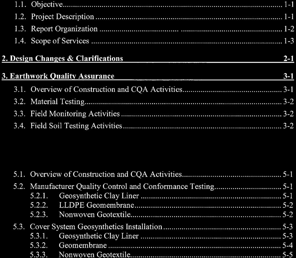
5 1. Introduction 1.1. Objective This construction quality assurance (CQA) report has been developed on behalf of the (Trust) to summarize the monitoring and testing program conducted by Malcolm Pirnie, Inc. during reconstruction of the cover system for the Category I (CAT I) Landfill - Cell 3 Cover System Reconstruction at the Former ASARCO Smelter Site (Site) located in El Paso, Texas. This report was prepared for the Trust by Mr. Steve Richey (CQA Manager), Ms. Rachel Jennings (Liner CQA Engineer) and reviewed by Scott Brown (Project Manager) and John Sparks, P.E. (Engineer of Record) Project Description The Site is located within the limits of El Paso, Texas. The main smelter site occupied an area of approximately 120 acres bounded by U.S. Interstate Highway 10 (I-10) on the east and U.S. Highway 85 (Paisano Drive) on the west as shown in the Site Vicinity Map (see Figure 1). As part of the remediation activities and construction activities at the site, Cell 3 (formerly Pond 6) was completed in 2008 for use as a Category I landfill. In order to meet the long term requirements of the site, Pond 6 required partial redesign and reconstruction. Malcolm Pirnie designed and prepared the Design Drawings (see Appendix A) for the new Cell 3 cover system and served as the Project Manager for the construction project. The ARCADIS Construction & Environmental Services group (CES) served as the General Contractor and completed earthwork activities for the project and American Environmental Group, Ltd. (AEG) of Richfield, Ohio installed the geosynthetic components of the cover system. Field and laboratory testing of soils was conducted by AMEC Environment & Infrastructure (AMEC), Inc. of El Paso, Texas. Laboratory testing of geosynthetic materials for conformance analysis was conducted by TRI Environmental, Inc. (TRI) of Austin, Texas. CQA surveying was completed by Land-Mark Professional Surveying, Inc. (Land-Mark) of El Paso, Texas. Malcolm Pirnie performed CQA monitoring, data review, field documentation and prepared this report. Cell 3 cover reconstruction included the following: Removal of existing sandy clay cover. Removal of the existing temporary cover system from bottom to top, geosynthetic clay liner (GCL), 40 mil textured linear low-density polyethylene (LLDPE) geomembrane, and double sided geocomposite. 1-1
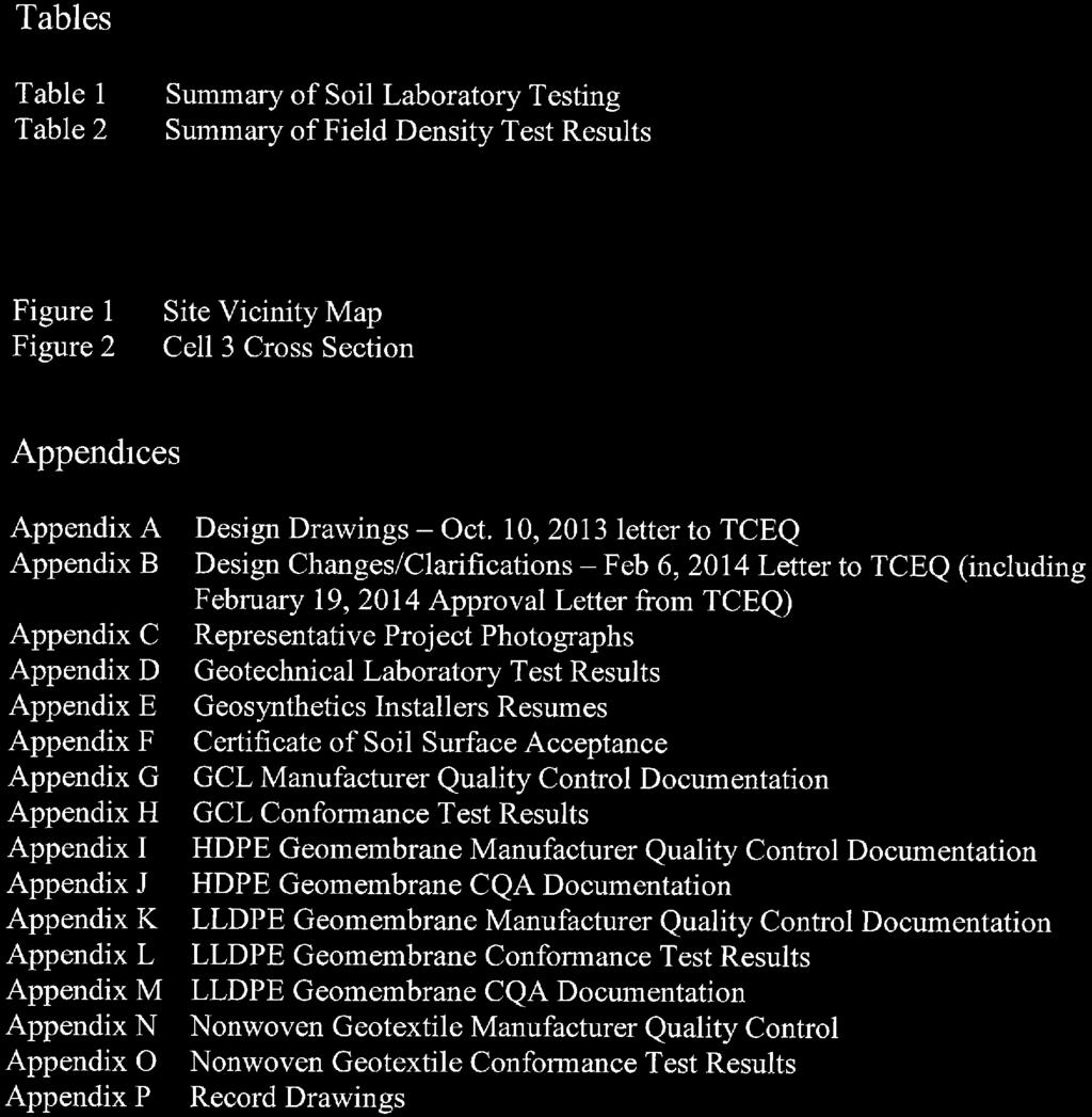
6 Section 1 Introduction Repair of HDPE baseliner geosynthetic materials from damage caused from cover removal. Excavation of Category I material to approximate elevation 3,787 feet. The Category I material was disposed in Cell 4. Placement of 18-inch-thick foundation layer. Installation of permanent cover system from bottom to top, GCL, 40 mil LLDPE geomembrane, nonwoven geotextile. Placement of 18-inch-thick layer of clean 1-inch minus soil cover material Report Organization This CQA Report is organized as follows: Design clarifications and changes are presented in Section 2. An overview of the construction activities and a description of the CQA monitoring and testing activities performed during placement of the prepared foundation (18-inch-thick subgrade layer beneath the geosynthetic components of the cover system) are provided in Section 3. An overview of the construction activities and a description of the CQA monitoring and testing activities performed during placement of the soil cover material (18-inch-thick layer over the geosynthetic components of the cover system) are provided in Section 3. An overview of repair activities and description of the CQA monitoring and testing activities performed on the existing Cell 3 baseliner is presented in Section 4. An overview of the construction activities and a description of the CQA monitoring and testing activities performed during installation of the GCL are provided in Section 5. An overview of the construction activities and a description of the CQA monitoring and testing activities performed during installation of the LLDPE geomembrane are provided in Section 5. An overview of the construction activities and a description of the CQA monitoring and testing activities performed during installation of the nonwoven geotextile are provided in Section 5. A summary and conclusions of the CQA monitoring and testing activities performed by Malcolm Pirnie are presented in Section 6. Documentation presenting the results of the CQA monitoring and testing activities performed by Malcolm Pirnie for the cover system is contained in the appendices to this report. The appendices are organized as follows: Design drawings/october 10, 2013 letter to TCEQ are presented in Appendix A. 1-2
7 Section 1 Introduction Design changes/clarifications/february 6, 2014 letter to TCEQ is presented in Appendix B. Representative photographic documentation of construction activities is provided in Appendix C. Material laboratory test results for structural fill soils, used for the foundation layer, final cover, and cover system anchor trench are provided in Appendix D. Geosynthetics installers resumes are presented in Appendix E. Installer s Certificate of Soil Surface Acceptance is presented in Appendix F. Documentation associated with the GCL is provided in Appendices G and H: - the manufacturer's quality control (QC) documentation - conformance test results Documentation associated with the 60 mil high-density polyethylene (HDPE) geomembrane is provided in Appendices I and J: - the manufacturer's QC documentation - CQA documentation Documentation associated with the 40-mil LLDPE geomembrane is provided in Appendices K through M: - the manufacturer's QC documentation - conformance test results - CQA documentation Documentation associated with the nonwoven geotextile is provided in Appendices N and O: - the manufacturer's QC documentation - conformance test results Record drawings prepared and sealed by the CQA professional land surveyor showing the elevations of the top of subgrade and top of the prepared subgrade for thickness verification and the geomembrane panel layout for the cover system are presented in Appendix P Scope of Services The scope of CQA monitoring, testing and field documentation services performed by Malcolm Pirnie during construction of the cover system for Cell 3 included the technical review of preconstruction test results, implementation of field CQA operations, technical review of field documentation, and preparation of this report. These activities were documented to satisfy the following project documents: Cell 3 Cover System, Former Smelter Site, El Paso, Texas, prepared by Malcolm Pirnie, 3 sheets, September 2013 and 1 sheet, January 2014 (Design Drawings) (see Appendix A and B) 1-3
8 Section 1 Introduction Material Specifications and Construction Quality Assurance Plan, Rev. 2, prepared for the Category I Landfill - Cell 4 by Geosyntec, January 2013; specifically Section 7-Geomembranes, Section 8-Geotextiles, Section 10- Geosynthetic Clay Liners, Section 11-CQA Surveying, Section 12-CQA Documentation (Specifications) The following activities were performed as part of Malcolm Pirnie s CQA services: Collecting samples of onsite soils and offsite soils for laboratory testing. Reviewing laboratory test results to verify that the soils for the new cover system met the requirements of the Design Drawings and Specifications. Monitoring construction of structural fill and preparation of the subgrade surface prior to installation of the GCL. Testing the in-situ moisture/unit weight (i.e., field moisture/density testing) of the compacted structural fill to verify that values were within the required range and met the requirements of the Design Drawings. Monitoring excavation of the perimeter anchor trench prior to placement of geosynthetics and subsequent backfilling of the anchor trench following the placement of geosynthetics. Reviewing manufacturer QC documentation and conformance test documentation for the geosynthetics (i.e., GCL, geomembrane, and nonwoven geotextile) to verify that they met the requirements of the CQA Plan. Tracking the geosynthetics rolls delivered to the site. Visually inspecting the geosynthetics rolls stored at the site to verify that the rolls had not been damaged during transportation and that the rolls were being stored in a manner that protected them from dirt, debris, and damage. Monitoring the deployment and seaming of GCL panels. Monitoring the deployment and seaming of geomembrane panels and marking damaged locations for repair. Monitoring geomembrane trial seaming operations and field testing of trial seams at the beginning of each seaming period. Monitoring geomembrane production seaming operations, including cleaning of the seam prior to welding. Monitoring nondestructive testing of geomembrane seams. Selecting geomembrane seam destructive sample locations, monitoring sample collection, monitoring field testing of seam samples, forwarding destructive samples to the offsite geosynthetics laboratory, and reviewing laboratory test results. Monitoring performance of geomembrane repairs and testing of the repairs. 1-4
9 Monitoring placement of nonwoven geotextile. Section 1 Introduction Monitoring sewing of nonwoven geotextile and marking locations for repair; and reviewing survey data (prepared subgrade elevations and thickness and geomembrane panel layout, including repair and destructive sample locations) provided by the CQA surveyor. 1-5
10 2. Design Changes & Clarifications Three design changes and one design clarification was described in the February 6, 2014 letter to TCEQ and approved by TCEQ on February 19, 2014 (both letters presented in Appendix B). They include the following: Design Changes: 1. The GCL material, Bentomat CLT, was replaced with Bentomat DN. Bentomat DN is the same material that was used for the baseliner system of Cell The cover system was extended beyond and below the 3,788 feet elevation and terminated in a new anchor trench located approximately 3 feet outboard of the existing cover system anchor trench. As a result of the original Cell 3 cover system geosynthetics being removed, the Category I anchor trench was reused for the new cover system geosynthetics as shown in the crosssection depicted in Figure 2. This design change is more fully discussed in Section The original Cell 3 cover included a double-sided geocomposite which was replaced with a 12 oz. nonwoven geotextile for the Cell 3 reconstruction. The reason for replacement of the geocomposite was because Cell 3 was originally designed to temporarily convey any infiltrating precipitation to a perimeter drain at the toe of Cell 3. The perimeter drain was no longer needed as part of the overall site drainage system due to future plans for a final soil cover system. Cell 3 will be covered with additional soil preventing infiltration and have other surface drainage components managing runoff in this area. The nonwoven geotextile will cushion and protect the geomembrane liner from potential damage during installation of the overlying soil cover material. Design Clarification No. 1 - The 18-inch-thick foundation layer was comprised of select unscreened material from the East Borrow Source and due diligence was taken during excavation and placement to minimize the amount of rock that exceeds 1-inch in size. After the first 12-inch-thick lift was placed and compacted with a smooth drum compacter, the surface was inspected to determine methodology was acceptable to continue for the final 6-inch-thick lift. The material was deemed acceptable and was used for the subsequent 6-inch-thick lift. The surface was inspected by the field engineer and approved prior to commencing GCL installation. 2-1
11 3. Earthwork Quality Assurance 3.1. Overview of Construction and CQA Activities Construction activities commenced on October 19, 2013 with removal of the existing clean sandy clay cover. The sandy clay cover was removed, stockpiled and eventually transported to Cell 4 for use as interim cover and a small portion was used for the second lift of the Cell 3 foundation layer. The original Cell 3 cover system geosynthetics were removed. The Category I anchor trench was reused for the new cover system geosynthetics as shown in the cross-section depicted in Figure 2. On November 5, 2013, Category I material excavation and hauling to Cell 4 began. The Category I material was excavated to an elevation of approximately 3,787 feet as shown in the Design Drawings (see Appendix A). The Category I material was graded to achieve a crown along the center portion of the cell. Clean soil was excavated and transported from the East Borrow Source along with a small portion of the former Cell 3 cover material and placed as the foundation layer. In conformance with the Design Drawings, two lifts of foundation layer material were moisture conditioned and compacted to a minimum 90 percent relative compaction. The surface of the foundation layer was inspected and rocks that exceeded 1-inch size were removed and replaced with compacted one-inch minus material. Malcolm Pirnie personnel provided monitoring and documentation of the foundation fill placement. Fill soils were placed and compacted in horizontal lifts. In general, the soil was transported to the work area in 40-ton (T) articulated haul trucks and was spread by a dozer in approximately 6-inch- to 12-inch-thick loose lifts. Moisture was added utilizing water trucks as needed during placement. Compaction of the soil within each lift was accomplished utilizing a Cat CS56 pad foot compactor and loaded 40T haul trucks. The soil was compacted to minimum 90 percent of its Modified Proctor maximum dry unit weight at moisture contents at -2 to +2 percent of the Modified Proctor optimum moisture content. The degree of compaction and moisture content were verified in the field at various locations by AMEC. Verification was achieved using a nuclear density gauge, as described in Section 3.4. After the foundation layer was installed and approved, the GCL, geomembrane and geotextile layers were installed (see Section 5). The 12 oz. nonwoven geotextile was covered by two lifts of 3/8-inch minus material imported from Jobe Materials, L.P. which conformed to the 1-inch minus requirement in the Design Drawings. The two lifts of soil cover were track-packed with a dozer as required in the Design Drawings. 3-1
12 Section 3 Earthwork Quality Assurance Land-Mark surveyed the top of the soil layers (foundation layer and soil cover material), at designated control points, to verify that the required cover thicknesses were achieved within a tolerance of ± 0.1 feet. A sealed record drawing prepared by Land-Mark is provided in Appendix P Material Testing Structural fill materials used for the foundation layer, cover material, and cover system anchor trench were sampled by Malcolm Pirnie and tested by an AMEC. The laboratory testing included particle size analysis, Modified Proctor, moisture content, and Atterberg limits. The laboratory test results are summarized in Table 1 and test reports for the collected samples are included in Appendix D Field Monitoring Activities As part of the field monitoring program, Malcolm Pirnie observed the following construction activities: Existing cover system removal Grading of waste subgrade Soil layer placement and compaction 3.4. Field Soil Testing Activities As part of the CQA activities, AMEC performed in-situ moisture/density tests on compacted lifts of soil fill (foundation layer and anchor trench). The tests were performed in accordance with ASTM D6938. Results of the field moisture/density tests are summarized in Table 2. The soils used for the foundation layer were compacted to minimum 90 percent of maximum dry density at -2 to +2 percent of optimum moisture content, as determined by Modified Proctor test results. The anchor trench backfill was compacted to minimum 90 percent of maximum dry density. The degree of compaction and moisture content were verified in the field at various locations by AMEC using a nuclear density gauge. A total of 15 passing field moisture/density tests were performed on the approximately 4,500 cubic yards (CY) of foundation material and a total of six passing field moisture/density tests were performed on the approximately 160 CY of anchor trench backfill. The number of completed field moisture/density tests exceeds the one test per 1,000 CY frequency specified in the Specifications. 3-2
13 4. Repair Activities While removing the temporary Cell 3 cover material, the excavator bucket punctured the existing baseliner 60-mil HDPE geomembrane in 29 locations along the existing perimeter anchor trench, beyond the slope crest of the baseliner. In three of the 29 locations, the GCL was also punctured. Repairs to the geomembrane and GCL components of the Cell 3 baseliner system were completed on April 7 and 8, AEG completed the repairs in accordance with the Specifications. Resumes of AEG s repair crew are provided in Appendix E. Construction oversight and CQA observation activities were performed by Malcolm Pirnie representatives Bill Sabatka and Rachel Jennings. In areas where the GCL needed repair, the puncture in the overlying geomembrane was widened to evaluate the damage to the GCL. A piece of GCL was placed over the location to measure and ensure a minimum 1-foot overlap beyond the edge of the GCL puncture in all directions. The GCL was then inserted beneath the geomembrane opening and spread flat. The GCL material used for the repair was manufactured by CETCO of Hoffman Estates, Illinois. Manufacturing quality control documentation and conformance test results for the GCL material are provided in Appendices G and H, respectively. Prior to extrusion welding the geomembrane repairs, AEG prepared trial seams in accordance with the Specifications. The trial seams were field tested by AEG in the presence of Malcolm Pirnie using a field tensiometer to ensure that the resulting peel and shear strength values met or exceeded the requirements listed in the Specifications. Results of the trial seam testing of the 60 mil HDPE geomembrane are presented in Appendix J. Geomembrane repairs were performed by placing a piece of 60 mil HDPE geomembrane over the repair location to measure and ensure a minimum overlap of 6 inches beyond the edge of the defect. The geomembrane repair was then temporarily heat bonded over the geomembrane puncture to hold the repair in place. The edges of the repair and the existing geomembrane were cleaned by mechanical abrasion and inspected for moisture and excess debris in accordance with the Specifications. The perimeter of the repair was then sealed to the existing geomembrane with an extrusion weld. Geomembrane repairs were non-destructively tested by AEG and monitored by Malcolm Pirnie, using a vacuum box. Results of the non-destructive testing performed during the repair of the baseliner system geomembrane are presented in Appendix J. 4-1
14 Section 4 Repair Activities The 60-mil geomembrane material used for the repairs was manufactured by GSE Lining Technology, LLC. (GSE) of Houston, Texas. Manufacturing quality control documentation for the 60 mil HDPE geomembrane is provided in Appendix I. The locations of the baseliner system geomembrane repairs are included in Appendix P. Representative photographic documentation of the repairs to the baseliner geomembrane is provided in Appendix C. 4-2
15 5. Cover System Geosynthetics Quality Assurance 5.1. Overview of Construction and CQA Activities The cover system for Cell 3 consists of the following components, from bottom to top: 18-inch-thick prepared foundation; reinforced GCL with a hydraulic conductivity cm/s; 40-mil-thick textured LLDPE geomembrane; 12 oz. nonwoven geotextile; and 18-inch-thick soil cover material. The cover system geosynthetics were installed by AEG from April 7, 2014 through April 11, As a result of the existing Cell 3 cover system geosynthetics being entirely removed, its anchor trench location was reused for the new cover system geosynthetics. Details regarding geosynthetic material testing and installation is provided below in Sections 5.2 and Manufacturer Quality Control and Conformance Testing Geosynthetic Clay Liner The GCL used for Cell 3 was manufactured by CETCO of Hoffman Estates, Illinois. A total of 43 GCL rolls were delivered to site for the project. Each roll of GCL measured approximately 14.5 feet wide by 150 feet long. Thus, the total area of the delivered rolls was approximately 93,525 square feet (SF). It should be noted that approximately nine rolls of GCL were not used during cover construction due to the use of the existing cover system anchor trench location. Results of the manufacturer s QC testing and the conformance testing for the GCL rolls are provided in Appendices G and H, respectively. Based on the Specifications, GCL conformance testing was to be performed at a frequency of one sample per 250,000 SF (with minimum one per lot). Malcolm Pirnie obtained and shipped two GCL samples to TRI for conformance testing. Based on the conformance test results, both samples met the specified testing values provided in the Specifications. Per the required test frequency and quantity of material delivered to the site and due to the material being produced from two lots, two conformance tests were required. Therefore, the number of conformance tests performed on the GCL met the requirements of the Specifications. 5-1
16 Section 5 Cover System Geosynthetics Quality Assurance Based on the results of the manufacturer QC documentation and the conformance tests, the GCL rolls used to construct the Cell 3 cover system met the requirements of the Specifications LLDPE Geomembrane The 40-mil textured LLDPE geomembrane used for the cover system of Cell 3 was manufactured by AGRU America of Georgetown, South Carolina. A total of six rolls of 40 mil textured LLDPE geomembrane were delivered to site and all but half of one roll was used for the project. Each roll of geomembrane measured approximately 23 feet wide by 710 feet long. Thus, the total area of the delivered rolls was approximately 97,980 SF. Results of the manufacturer s QC testing and the conformance testing for the geomembrane rolls are provided in Appendices K and L, respectively. Based on the Specifications, geomembrane conformance testing was to be performed at a frequency of one sample per 100,000 SF (with minimum one per lot). Malcolm Pirnie obtained and shipped one geomembrane sample to TRI for conformance testing. Based on the conformance test results, the sample met the specified testing values provided in the Specifications. Per the required test frequency and quantity of material delivered to the site, only one conformance test was required. Therefore, the number of conformance tests performed on the geomembrane met the requirements of the Specifications. Interface shear strength testing (LLDPE/GCL) was also performed as required by the Specifications as part of the conformance testing process. Based on the results of the manufacturer QC documentation and the conformance tests, the geomembrane rolls used to construct the Cell 3 cover system met the requirements of the Specifications with the exception of one of two interface shear strength tests using a normal stress of 300 psf which achieved a Corrected Large Displacement Shear Stress of 126 psf (required is 140 psf). The other two normal stress tests for the same sample, performed at 5,000 and 10,000 psf, exceeded the required minimum Peak and Large Displacement shear strengths of the Specifications. Since the Cell 3 cover system will be covered by a clean soil cover/cap having a total approximate thickness of 4 feet, Malcolm Pirnie does not consider the one failed interface shear strength test, performed at normal stress of 300 psf, to have a significant impact to overall stability Nonwoven Geotextile The 12 oz. nonwoven geotextile used for the cover system of Cell 3 was manufactured by GSE of Houston, Texas. A total of 19 rolls of 12 oz. nonwoven geotextile were delivered to the site. It should be noted that approximately six rolls of geotextile were not used during cover construction due to the use of the existing cover system anchor trench location. Each roll of geotextile measured approximately 15 feet wide by 400 feet long. Thus, the total area of the delivered rolls was approximately 114,000 SF. Results of the manufacturer s QC testing and the conformance testing for the geotextile are provided in Appendices N and O, respectively. 5-2
17 Section 5 Cover System Geosynthetics Quality Assurance Based on the Specifications, geotextile conformance testing was to be performed at a frequency of one sample per 250,000 SF (with minimum one per lot). Malcolm Pirnie obtained and shipped one geotextile sample to TRI for conformance testing. Based on the conformance test results, the sample met the specified testing values provided in the Specifications. Per the required test frequency and quantity of material delivered to the site, only one conformance test was required. Therefore, the number of conformance tests performed on the geotextile met the requirements of the Specifications. Based on the results of the manufacturer QC documentation and the conformance tests, the geotextile rolls used to construct the Cell 3 cover system met the requirements of the Specifications Cover System Geosynthetics Installation Upon delivery to the site, the geosynthetic materials were unloaded at a designated covered, concrete area near Cell 3 and stacked two rolls high. Malcolm Pirnie performed an inventory of all delivered geosynthetic materials to verify that the roll numbers matched the approved manufacturer s QC documentation. Prior to installation of geosynthetics over the prepared subgrade, the surface of the subgrade was inspected by AEG and Malcolm Pirnie to confirm that it was smooth and uniform, and free of irregularities, dimples, loose soil, or abrupt changes in grade. The prepared subgrade was smooth drum rolled by CES and surveyed by Land-Mark. A Certificate of Soil Surface Acceptance was signed by AEG and Malcolm Pirnie and is provided in Appendix F. The following sections provide additional information related to the installation of the Cell 3 cover system geosynthetics Geosynthetic Clay Liner Installation of GCL over the prepared subgrade began on April 7, A forklift with a spreader bar was used to transport rolls of GCL to the work area. GCL was deployed along the plateau and the sideslopes of Cell 3 by positioning the roll over the anchor trench on one side of the cell and using a Skidsteer positioned on the opposite side of the cell with a winch system attached to the material, pulling the GCL off the roll and across the cell with the aid of several laborers. Adjacent GCL panels were overlapped a minimum of 6 inches along longitudinal seams and a minimum 12 inches along transverse seams in accordance with manufacturer s specifications. Supplemental bentonite was applied along the length of transverse seams in accordance with the manufacturer s recommendations. All GCL seams were heat bonded to hold the GCL in place when deploying the overlying LLDPE geomembrane. GCL seams were monitored by Malcolm Pirnie for workmanship and continuity. Sand bags were used temporarily to secure the GCL along the sideslopes and plateau area of the cell and were removed prior to placement of the overlying LLDPE geomembrane. 5-3
18 Geomembrane Section 5 Cover System Geosynthetics Quality Assurance Installation of the 40-mil textured LLDPE geomembrane began on April 8, A forklift with a spreader bar was used to transport rolls of geomembrane to the work area. Occasionally, rolls of geomembrane were temporarily stored adjacent to the construction area prior to deployment. Geomembrane was deployed along the plateau and the sideslopes of Cell 3 by positioning the roll over the anchor trench on one side of the cell and using a Skidsteer positioned on the opposite side of the cell with a winch system attached to the material pulling the geomembrane material off the roll and across the cell with the aid of several laborers. After the panels were placed, they were overlapped in accordance with the Specifications. The Panel Placement Log is provided in Appendix M. Prior to production seaming, AEG prepared trial seams, in accordance with the Specifications for each combination of seaming equipment and operator used during the work period. The trial seams were field tested by AEG in the presence of Malcolm Pirnie using a field tensiometer to confirm that the resulting peel and shear strength values met or exceeded the requirements listed in the Specifications. Results of the trial seam testing of the 40-mil LLDPE geomembrane are documented in the Trial Seam Log provided in Appendix M. Following Malcolm Pirnie s approval of the trial seams, AEG inspected and verified that the geomembrane overlap areas were clean and free of moisture, dust, dirt, and debris of any kind. Once cleaned, production seams were fabricated using double-track fusion welders. Seaming operations were monitored by Malcolm Pirnie for workmanship and continuity. The integrity of double-track fusion seams were evaluated in the field by air pressure testing the seams in accordance with the Specifications and ASTM D5820. All non-destructive testing was performed by AEG and monitored by Malcolm Pirnie. The Production Seaming Log, which includes the results of the air pressure testing, is provided in Appendix M. Destructive samples were obtained in accordance with the Specifications to further evaluate the integrity of the field seams. Based on the total production seam length of 3,509 feet and a minimum sample frequency of one per 500 linear feet per welder, the required number of destructive samples was approximately eight. Consistent with the required frequency provided in the Specifications, Malcolm Pirnie identified eight destructive sample locations. Each destructive sample was divided into three specimen and utilized as follows: One specimen was field tested by AEG for peel and shear strength using a calibrated field tensiometer. One specimen was archived by Malcolm Pirnie. One specimen was sent to TRI to be independently tested for peel and shear strength. 5-4
19 Section 5 Cover System Geosynthetics Quality Assurance Passing results were obtained from all eight destructive samples designated as DS-1 through DS-8. The field and laboratory destructive test results are documented in the Destructive Test Log provided in Appendix M. Geomembrane repairs were performed at intersections of three or more panels, seam destructive sample locations, and where geomembrane defects were identified. Repair activities included placing a piece of 40 mil LLDPE geomembrane over the repair location and ensuring a minimum overlap of 6 inches beyond the edge of the defect. The geomembrane repair was then temporarily heat bonded over the geomembrane puncture to hold the repair in place. The edges of the repair and the existing geomembrane were cleaned by mechanical abrasion and inspected for moisture and excess debris in accordance with the Specifications. The perimeter of the repair was then sealed to the existing geomembrane with an extrusion weld. In cases where large wrinkles developed, the geomembrane was cut along the ridge of the wrinkle to achieve a flat overlap and the cut area was temporarily heat bonded, cleaned and sealed with an extrusion weld. Extrusion welds were also used to repair minor irregularities or surface flaws. The integrity of the extrusion welded repairs was evaluated in the field by vacuum box testing the weld in accordance with the Specifications and ASTM D All non-destructive testing was performed by AEG and monitored by Malcolm Pirnie. Geomembrane repair locations and nondestructive testing of the repairs are documented on the Repair Summary Log provided in Appendix M. After the geomembrane was deployed, seamed, tested, repaired, and found to meet the requirements of the Specifications, Land-Mark surveyed the geomembrane and created a record drawing. This drawing, which is provided in Appendix P, includes the geomembrane panels, destructive sample locations, and repair locations documented by Malcolm Pirnie. Sand bags were used temporarily to secure the geomembrane along the sideslopes and plateau area of the cell and were removed prior to placement of the overlying nonwoven geotextile Nonwoven Geotextile Installation of the 12 oz. nonwoven geotextile by AEG began on April 9, 2014 and was completed on April 11, A forklift with a spreader bar was used to transport rolls of the material to the work area. Nonwoven geotextile was deployed along the plateau and the sideslopes of Cell 3 by positioning the roll over the anchor trench on one side of the cell and using a Skidsteer positioned on the opposite side of the cell with a winch system attached to the material pulling the geotextile off the roll and across the cell with the aid of several laborers. Adjacent geotextile panels were overlapped a minimum of 12 inches in both machine and transverse directions in accordance with manufacturer s recommendations. All geotextile seams were sewn together using polyester thread, a flat prayer seam and one row of stitching. Geotextile seams were monitored by Malcolm Pirnie for workmanship and continuity. 5-5
20 Section 5 Cover System Geosynthetics Quality Assurance Sand bags were used to temporarily secure the geotextile along the sideslopes and plateau area of the cell and were removed prior to placement of the overlying cover materials. 5-6
21 6. Conclusion The reconstruction of the cover system for the Category I Landfill - Cell 3 at the Site in El Paso, Texas observations and testing occurred from October 19, 2013 to June 5, Malcolm Pirnie provided CQA during construction activities. This report documents the CQA activities conducted by Malcolm Pirnie during reconstruction of the Cell 3 cover system. Based on the results of the monitoring and testing program conducted by Malcolm Pirnie, the new Cell 3 cover system was constructed in general accordance with the requirements of the Specifications, Design Drawings, and standard of practice. 6-1
Liner Construction & Testing Guidance Overview
 Liner Construction & Testing Guidance Overview Ruben Meza, Jr., P.E. Waste Permits Division Municipal Solid Waste Permits Section 2017: TCEQ Environmental Trade Fair Agenda Summary of Revised Guidance
GEOMEMBRANE FIELD INSTALLATION
 GEOMEMBRANE FIELD INSTALLATION CONTENTS Introduction Quality Control and Quality Assurance Types of lining systems Basic Lining Design Executive Lining Design Basic Lining Design Specification Executive
Drop-In Specifications INTEGRATED DRAINAGE SYSTEM GEOMEMBRANE
 Drop-In Specifications INTEGRATED DRAINAGE SYSTEM GEOMEMBRANE The following specification is a sample guideline to be customized by the engineer for preparing site specific specification. This information
INSTALLATION GUIDELINES FOR GEOTEXTILES USED IN FILTRATION AND DRAINAGE APPLICATIONS
 INSTALLATION GUIDELINES FOR GEOTEXTILES USED IN FILTRATION AND DRAINAGE APPLICATIONS Prepared by TenCate Geosynthetics North America 365 South Holland Drive Pendergrass, GA 30567 Tel: (706) 693-2226 Fax:
SPECIAL SPECIFICATION 3687 Impermeable Liner
 1993 Specifications CSJ s 0569-01-043 & 0945-04-025 SPECIAL SPECIFICATION 3687 Impermeable Liner 1. Description. This Item shall govern for the furnishing and installation of the impermeable liner (geomembrane)
1993 Specifications CSJ SPECIAL SPECIFICATION ITEM Impermeable Liner
 1993 Specifications CSJ 0128-01-085 SPECIAL SPECIFICATION ITEM 5327 Impermeable Liner 1. Description. This Item shall govern for the furnishing and installation of the impermeable liner (geomembrane) shown
PVC GEOMEMBRANE FABRICATION AND INSTALLATION SPECIFICATION
 PVC GEOMEMBRANE FABRICATION AND INSTALLATION SPECIFICATION August 20, 2006 PVC Geomembrane Institute Technology Program 2215 Newmark Civil Engineering Laboratory 205N. Mathews Ave. Urbana, IL 61801 217-333-3929
Leak Location Geosynthetic Materials in Base Liner Systems. NY Federation SWANA. May, 2014
 Leak Location Geosynthetic Materials in Base Liner Systems NY Federation SWANA May, 2014 Different ELI Surveys A. Covered Electrical Liner Integrity (ELI) Survey Dipole Method Suitable for water or soil
SWANA/A&WMA s. Third Annual Landfill Operator s Training Geosynthetics in Landfills. February 13, 2013
 SWANA/A&WMA s Third Annual Landfill Operator s Training Geosynthetics in Landfills February 13, 2013 Geosynthetics Products Applications Current Lining Requirements Tips 2 Geosynthetics polymeric products
SECTION 2.5. Construction Quality Assurance Plan
 SECTION 2.5 Construction Quality Assurance Plan Table of Contents 1.0 Purpose and Scope... 1-1 1.1 Purpose... 1-1 1.2 Scope... 1-1 2.0 Operator and CQA Roles, Responsibilities, and Qualification... 2-1
Section Specification for Geotextile Used in Permanent Erosion Control Application
 Project Name: Project Number: 1 GENERAL Section 02370 Specification for Geotextile Used in Permanent Erosion Control Application 1.1 SECTION INCLUDES A. Geotextile to prevent soil loss resulting in excessive
UNIFIED FACILITIES GUIDE SPECIFICATIONS
 USACE / NAVFAC / AFCEC / NASA UFGS-02 66 00 (February 2010) ----------------------------- Preparing Activity: USACE Superseding UFGS-02 66 00 (April 2006) UNIFIED FACILITIES GUIDE SPECIFICATIONS References
Geosynthetics. Work platforms built with geotextile tubes at the Lach Huyen Bridge. GMA TECHLINE Exposed GM? Deformations?
 FEBRUARY/MARCH 2016 VOLUME 34 NUMBER 1 SUBSCRIBE AT GeosyntheticsMagazine.com GMA TECHLINE Exposed GM? Deformations? For landfill drainage layer GIROUD & HAN Geosynthetics and unpaved roads Geosynthetics
Consulting Engineers and Scientists. Closure Plan. Submitted by: GEI Consultants, Inc Voyager Drive Green Bay, Wisconsin
 Consulting Engineers and Scientists Regulation Compliance Report Submitted to: We Energies 333 West Everett Street, A231 Milwaukee, Wisconsin 53203 Submitted by: GEI Consultants, Inc. 3159 Voyager Drive
D.P.E. Enviroliner. geotextile protection layer. covering new ground 2016
 LEVEL 7 osynthetic clay liner www.gundle.co.za H.D.P.E. Enviroliner geosynthetic clay liner geotextile protection layer D.P.E. Enviroliner solid waste sand (leachate collection) geotextile protection layer
Engineering Report: Appendix F Volume 3 Landfill Liner Construction Specifications COWLITZ COUNTY HEADQUARTERS LANDFILL PROJECT COWLITZ COUNTY, WASHIN
 Engineering Report: Appendix F Volume 3 Landfill Liner Construction Specifications COWLITZ COUNTY HEADQUARTERS LANDFILL PROJECT COWLITZ COUNTY, WASHINGTON TECHNICAL SPECIFICATIONS GENERIC CELL CONSTRUCTION
GEOMEMBRANE AND DRAINAGE INSTALLATION SPECIFICATION
 GEOMEMBRANE AND DRAINAGE INSTALLATION SPECIFICATION The information provided in this manual uses current quality control and quality assurance standards within the geomembrane industry. It is the sole
INTERNATIONAL ASSOCIATION OF GEOSYNTHETICS INSTALLERS (IAGI) AND FABRICATED GEOMEMBRANE INSTITUTE (FGI)
 AND FABRICATED GEOMEMBRANE INSTITUTE (FGI)") INTERNATIONAL ASSOCIATION OF GEOSYNTHETICS INSTALLERS (IAGI) AND FABRICATED GEOMEMBRANE INSTITUTE (FGI) GUIDELINES FOR INSTALLATION OF: FACTORY FABRICATED LIGHTWEIGHT (
INTERNATIONAL ASSOCIATION OF GEOSYNTHETICS INSTALLERS (IAGI) AND FABRICATED GEOMEMBRANE INSTITUTE (FGI) GUIDELINES FOR INSTALLATION OF: FACTORY FABRICATED LIGHTWEIGHT (
Super Gripnet INTEGRATED DRAINAGE SYSTEM (IDS) GEOMEMBRANE
 GEOMEMBRANE") Super Gripnet INTEGRATED DRAINAGE SYSTEM (IDS) GEOMEMBRANE 1 The Plastics Experts. AGRU America s structured geomembranes are manufactured on state-of-the-art manufacturing equipment using the flat die
Super Gripnet INTEGRATED DRAINAGE SYSTEM (IDS) GEOMEMBRANE 1 The Plastics Experts. AGRU America s structured geomembranes are manufactured on state-of-the-art manufacturing equipment using the flat die
ENVIRONMENTAL ENGINEERING LAND SURVEYING
 ENVIRONMENTAL ENGINEERING LAND SURVEYING Closure Plan Scrubber Solids Pond No. 3 Sherburne County Generating Plant Introduction This plan describes the closure requirements for Scrubber Solids Pond No.
GRI White Paper #8. - on - Construction Quality Assurance-Inspectors Certification Program (CQA-ICP)
") Geosynthetic Certification Institute 475 Kedron Avenue Folsom, PA 19033-1208 USA TEL (610) 522-8440 FAX (610) 522-8441 GEI GRI GSI GAI GCI GII GRI White Paper #8 - on - Construction Quality Assurance-Inspectors
Geosynthetic Certification Institute 475 Kedron Avenue Folsom, PA 19033-1208 USA TEL (610) 522-8440 FAX (610) 522-8441 GEI GRI GSI GAI GCI GII GRI White Paper #8 - on - Construction Quality Assurance-Inspectors
Selecting the Right Closure Cap Option for Your Surface Impoundment or CCR Landfill
 2017 World of Coal Ash (WOCA) Conference in Lexington, KY - May 9-11, 2017 http://www.flyash.info/ Selecting the Right Closure Cap Option for Your Surface Impoundment or CCR Landfill Steven C. Lamb 1,
NOTICE OF INTENT. Submitted To: Bremo Power Station 1038 Bremo Bluff Road Bremo Bluff, VA 23022
 NOTICE OF INTENT TO CLOSE INACTIVE CCR SURFACE IMPOUNDMENTS NOTICE OF INTENT Bremo Power Station Submitted To: Bremo Power Station 1038 Bremo Bluff Road Bremo Bluff, VA 23022 Submitted By: Golder Associates
!!!!!!!!!!!!!!!! INSTALLATION!GUIDELINES!MANUAL! January!2018,!Revision!3.0! Advanced!Revetment!Technology!
 INSTALLATIONGUIDELINESMANUAL January2018,Revision3.0 Beforeutilizingthisdocumentas aninstallationtool,installers shoulddownloadthelatestversion oftheinstallationguidelines Manualfromthetechnical downloadssectionofourwebsite
SECTION 02230BP AGGREGATE BASE
 SECTION 02230BP AGGREGATE BASE This page is intentionally left blank. Fluor-B&W Portsmouth, LLC (FBP) SITE PREPARATION INFRASTRUCTURE PHASE 1 SPECIFICATION COVER SHEET Client: U.S. Department of Energy
GEOMEMBRANE INSTALLATION GUIDELINES AND SPECIFICATIONS FOR LLDPE 20, 30, AND 40 MIL UNREINFORCED & GEO-SKRIM SERIES REINFORCED LINERS.
 GEOMEMBRANE INSTALLATION GUIDELINES AND SPECIFICATIONS FOR LLDPE 20, 30, AND 40 MIL UNREINFORCED & GEO-SKRIM SERIES REINFORCED LINERS. TABLE OF CONTENTS SECTION PAGE 1.0 SUBGRADE PREPARATION 3 2.0 PANEL
Chesapeake Energy Center. Submitted To: Chesapeake Energy Center 2701 Vepco Street Chesapeake, VA 23323
 NOTICE OF INTENT TO CLOSE INACTIVE CCR SURFACE IMPOUNDMENT NOTICE OF INTENT Chesapeake Energy Center Submitted To: Chesapeake Energy Center 2701 Vepco Street Chesapeake, VA 23323 Submitted By: Golder Associates
APPENDIX A POND LINING TECHNICAL SPECIFICATIONS
 APPENDIX A POND LINING TECHNICAL SPECIFICATIONS City of Albany WTP-17-01, Backwash Ponds Improvements Project Seals Page For specification sections: 02227,02263,02676,02680 SEALS PAGE - 1of1 SECTION 02227
INSTALLATION GUIDELINES. Landfills and mines
 INSTALLATION GUIDELINES Landfills and mines Introduction Recommendations This installation manual gives general recommendations for the installation of the drainage geocomposites InterDRAIN and TechDRAIN
SPECIFICATIONS AND TECHNICAL REQUIREMENTS FOR THE MANUFACTURING AND INSTALLATION OF POLYETHYLENE GEOMEMBRANES
 SPECIFICATIONS AND TECHNICAL REQUIREMENTS FOR THE MANUFACTURING AND INSTALLATION OF POLYETHYLENE GEOMEMBRANES The following specification constitutes a guideline for the preparation of site specific geomembrane
Air-channel testing landfill geomembrane seams
 Air-channel testing landfill geomembrane seams Results from a recent workshop help minimize destructive testing By Timothy D. Stark, John Heap, Stuart Lange, Dave McLaury and Stanford Slifer Thermal welding
SKAPS GEOTEXTILE SUBSURFACE DRAINAGE
 SKAPS INDUSTRIES 335 Athena Drive, Athens, GA 30601 Ph: (706)-354-3700 Fax: (706)-354-3737 Email: contact@skaps.com DROP-IN SPECIFICATIONS SKAPS GEOTEXTILE SUBSURFACE DRAINAGE The following drop-in specification
Workshop On Capping Design In South Africa. Product Showcase By. Tyrone Naidoo
 Workshop On Capping Design In South Africa Product Showcase By Tyrone Naidoo Kaytech Introduction Kaytech providing Africa with Geosynthetics for over 40 years Offering geosynthetic solutions to corporations
AQUAMASTER INSTALLATION GUIDE
 AQUAMASTER INSTALLATION GUIDE PROUD MEMBER Geosynthetic Materials Association PROUD MEMBER Industrial Fabrics Association International TABLE OF CONTENTS 1. GENERAL...1 1.1. Scope...1 1.2. Applications...1
III.DRAINAGE. This section describes the use of geotextiles in underdrains for two different field conditions:
 III.DRAINAGE This section describes the use of geotextiles in underdrains for two different field conditions: Protected (or light duty installations) and, Unprotected (for heavy duty installations). Both
INSTALLATION OF GEOTEXTILE TUBES USED FOR COASTAL AND RIVERINE STRUCTURES GLOBAL SYNTHETICS PROTUBE GEOTEXTILE TUBE
 INSTALLATION OF GEOTEXTILE TUBES USED FOR COASTAL AND RIVERINE STRUCTURES GLOBAL SYNTHETICS PROTUBE GEOTEXTILE TUBE 1. SCOPE This practice provides guidelines for the installation of PROTUBE geotextile
CalTrans tackles The Merge
 February March 2007 Volume 25 Number 1 CalTrans tackles The Merge Geogrid reinforcement is key for huge Interstate widening project Tour the world's largest PVC membrane installation Designer's Forum:
UNIFIED FACILITIES GUIDE SPECIFICATIONS
 USACE / NAVFAC / AFCEC / NASA UFGS-02 56 13 (February 2010) ----------------------------- Preparing Activity: USACE Superseding UGGS-02 56 13 (October 2007) UNIFIED FACILITIES GUIDE SPECIFICATIONS References
Capping waste rock at a Superfund site An innovative design tackles pollution at a mining operation s waste repository.
 Capping waste rock at a Superfund site An innovative design tackles pollution at a mining operation s waste repository. The Gilt Edge mine is located in the northern Black Hills of South Dakota on private
SECTION EARTHWORK
 SECTION 02200 - EARTHWORK PART 1 GENERAL 1.1 SECTION INCLUDES A. Grading and Excavation B. Trenching C. Bedding D. Backfill and Compaction (New and Native) E. Aggregate Material F. Geotextile Fabric PART
A Collection and Removal System for Water in the Final Cover Drainage Layer
 Landfills A Collection and Removal System for Water in the Final Cover Drainage Layer A rainwater toe drainage system, by removing water from the final cover drainage layer, eliminates the possibility
POND SEALING OR LINING GEOMEMBRANE OR GEOSYNTHETIC CLAY LINER
 NATURAL RESOURCES CONSERVATION SERVICE CONSERVATION PRACTICE STANDARD POND SEALING OR LINING GEOMEMBRANE OR GEOSYNTHETIC CLAY LINER CODE 521 (NO.) DEFINITION A liner for an impoundment constructed using
THE ROLE OF SUCTION IN THE PERFORMANCE OF CLAY FILL RONALD F. REED, P.E. 1 KUNDAN K. PANDEY, P.E. 2
 THE ROLE OF SUCTION IN THE PERFORMANCE OF CLAY FILL RONALD F. REED, P.E. 1 KUNDAN K. PANDEY, P.E. 2 Abstract Plastic clay is commonly used as fill. Proper placement is the key to the performance of the
GEOSYNTHETICS ENGINEERING: IN THEORY AND PRACTICE
 GEOSYNTHETICS ENGINEERING: IN THEORY AND PRACTICE Prof. J. N. Mandal Department of Civil Engineering, IIT Bombay, Powai, Mumbai 400076, India. Tel.022-25767328 email: cejnm@civil.iitb.ac.in Module - 2
LANDFILL FINAL COVER AND MANAGEMENT OF LEACHATE SEEPS BELOW FINAL COVER
 LANDFILL FINAL COVER AND MANAGEMENT OF LEACHATE SEEPS BELOW FINAL COVER Ali Khatami, Ph.D., P.E. SCS Engineers 1900 NW Corporate Blvd. #W110 Boca Raton, Florida 33431 akhatami@scsengineers.com Abstract:
geotextiles bidim Nonwoven polyester geotextile Made in Australia Designed for performance RECYCLED
 geotextiles bidim Nonwoven polyester geotextile Made in Australia Designed for performance RECYCLED INTRODUCTION The use of geotextiles in construction projects around the world has grown substantially
geotextiles bidim Nonwoven polyester geotextile Made in Australia Designed for performance RECYCLED Quality ISO 9001
 geotextiles bidim Nonwoven polyester geotextile Made in Australia Designed for performance Quality ISO 9001 RECYCLED INTRODUCTION The use of geotextiles in construction projects around the world has grown
FIGURE 1 Crews finalizing 60-mil (1.5-mil), five-ply CSPE geomembrane liner with cap strips over field seams at the Palos Verdes Reservoir
, five-ply CSPE geomembrane liner with cap strips over field seams at the Palos Verdes Reservoir") FIGURE 1 Crews finalizing 60-mil (1.5-mil), five-ply CSPE geomembrane liner with cap strips over field seams at the Palos Verdes Reservoir EDITOR S NOTE Part 1 of Reviving the Palos Verdes Reservoir appeared
FIGURE 1 Crews finalizing 60-mil (1.5-mil), five-ply CSPE geomembrane liner with cap strips over field seams at the Palos Verdes Reservoir EDITOR S NOTE Part 1 of Reviving the Palos Verdes Reservoir appeared
Alternative Cover Systems
 Alternative Cover Systems RemTech 2017 October 13, 2017 Outline Capping solutions Why use alternate cover systems Exposed geomembrane cap systems Geosynthetic Turf cap systems What is it? How is it installed?
Exposed Geomembrane Cover Systems for Coal Ash Facilities
 2017 World of Coal Ash (WOCA) Conference in Lexington, KY - May 9-11, 2017 http://www.flyash.info/ Exposed Geomembrane Cover Systems for Coal Ash Facilities Clay Reichert, P.E. GSE Environmental, LLC,
Overview of Canal Lining Projects. Montana Association of Dam and Canal Systems October 5 and 6, Jack Haynes EDC Canal Linings, LLC Owner
 Overview of Canal Lining Projects Montana Association of Dam and Canal Systems October 5 and 6, 2011 Jack Haynes EDC Canal Linings, LLC Owner Scope of Study 34 Test Sections installed 18 Exposed Geomembranes
INSTALLATION QUALITY-ASSURANCE GUIDE FOR SOLMAX-GSE S CONDUCTIVE LINER
 INSTALLATION QUALITY-ASSURANCE GUIDE FOR SOLMAX-GSE S CONDUCTIVE LINER These instructions present some general guidelines for installing and surveying Solmax-GSE s smooth edged conductive backed geomembranes
The use of geosynthetics in the installation of ballast layers
 The use of geosynthetics in the installation of ballast layers C. Cilliers, Jones & Wagener (Pty) Ltd, South Africa, cilliers@jaws.co.za ABSTRACT The ballast layer is an essential element of any landfill
Long-Term Durability of a 20 mil PVC Geomembrane
 Long-Term Durability of a 20 mil PVC Geomembrane E. J. NEWMAN & T. D. STARK, Dept. of Civ. & Environmental Engrg., Univ. of Illinois, Urbana, IL, United States F. P. ROHE, Environmental Protection, Inc.,
TECHNICAL DROP-IN SPECIFICATIONS
 TECHNICAL DROP-IN SPECIFICATION Dura-Skrim N-Series & NT-Series Reinforced Polyethylene ISSUED DATE 25 AUGUST 2014 VALID DATE 25 SEPTEMBER 2014 The following technical drop-in specifications are provided
ACTIVITY: Geotextiles ES 12
 Targeted Constituents Significant Benefit Partial Benefit Low or Unknown Benefit Sediment Heavy Metals Floatable Materials Oxygen Demanding Substances Nutrients Toxic Materials Oil & Grease Bacteria &
HEAP LEACH PAD DESIGN AND CONSTRUCTION PRACTICES IN THE 21 ST CENTURY
 HEAP LEACH PAD DESIGN AND CONSTRUCTION PRACTICES IN THE 21 ST CENTURY By Allan J. Breitenbach, P.E., SME Member Vector Colorado LLC INTRODUCTION The mining industry has been using geomembrane liners for
MATERIAL SPECIFICATION FOR GEOTEXTILES
 ONTARIO PROVINCIAL STANDARD SPECIFICATION METRIC OPSS 1860 NOVEMBER 2004 MATERIAL SPECIFICATION FOR GEOTEXTILES TABLE OF CONTENTS 1860.01 SCOPE 1860.02 REFERENCES 1860.03 DEFINITIONS 1860.04 SUBMISSION
Geosynthetics and Their Applications
 GEOSYNTHETICS AND REINFORCED SOIL STRUCTURES Different Types of Geosynthetics and Their Applications K. Rajagopal, Professor Department of Civil Engineering IIT Madras, Chennai e-mail: gopalkr@iitm.ac.inac
SECTION AMENDED TOPSOIL
 SECTION 02486 AMENDED TOPSOIL PART 1 - GENERAL 1.01 SUMMARY A. Work described in this section includes requirements for soil amendments, soil preparation, preparation and finish grading of turf restoration
I N D U S T R I A L Y A R D S
 I N D U S T R I A L Y A R D S GEOTEXTILES INDUSTRIAL YARDS 1.0 Features of INDUSTRIAL PG 2 YARDS 2.0 How Typar geotextiles PG 2 work 4.0 Installation guide PG 7 5.0 Overlap and joining PG 8 6.0 Setting
V. EROSION CONTROL. -Drainage swales separation -Under rip-rap protected -Under rip-rap unprotected
 V. EROSION CONTROL This section describes three different types of erosion control applications where geotextiles can be used in conjunction with some form of stone or other energy dissipating material
CONSTRUCTION SPECIFICATION FOR RIP RAP, ROCK PROTECTION AND GRAVEL SHEETING
 ONTARIO PROVINCIAL STANDARD SPECIFICATION METRIC OPSS 511 FEBRUARY 1990 CONSTRUCTION SPECIFICATION FOR RIP RAP, ROCK PROTECTION AND GRAVEL SHEETING 511.01 SCOPE 511.02 REFERENCES 511.03 DEFINITIONS 511.04
Geosynthetic Institute GSI GRI GT13(b) ISO Version
 ISO Version") Geosynthetic Institute 475 Kedron Avenue Folsom, PA 19033-1208 USA TEL (610) 522-8440 FAX (610) 522-8441 GEI GRI GSI GAI GCI GII Revision 1: December 19, 2012 Revision Schedule on pg. 9 GRI GT13(b) ISO
Geosynthetic Institute 475 Kedron Avenue Folsom, PA 19033-1208 USA TEL (610) 522-8440 FAX (610) 522-8441 GEI GRI GSI GAI GCI GII Revision 1: December 19, 2012 Revision Schedule on pg. 9 GRI GT13(b) ISO
Experiences with Placement of Alternative Final Covers Presented by
 Experiences with Placement of Alternative Final Covers Presented by Leonard Butler, P.E., DEE, CSP Waste Management of Colorado, Inc. For ET 04 March 9, 2004 ET Cover Program Goals in Colorado: Provide
Leakage through Liners under High Hydraulic Heads. PH (512) ; FAX (512) ;
 ; FAX (512) ;") Weber, C.T., and Zornberg, J.G. (2005). Leakage through Liners under High Hydraulic Heads." Geosynthetics Research and Development in Progress, Eighteenth Geosynthetic Research Institute Conference (GRI-18),
Weber, C.T., and Zornberg, J.G. (2005). Leakage through Liners under High Hydraulic Heads." Geosynthetics Research and Development in Progress, Eighteenth Geosynthetic Research Institute Conference (GRI-18),
LiteEarth Advanced Synthetic Grass Geomembrane Liner INDEPENDENT THIRD PARTY PERFORMANCE TESTING REPORT. U.S. Patent No.
 LiteEarth Advanced Synthetic Grass Geomembrane Liner INDEPENDENT THIRD PARTY PERFORMANCE TESTING REPORT U.S. Patent No. 9151009 B2 Contents 1.0 INTRODUCTION...4 2.0 INDEX AND QUALITY CONTROL TESTS 2.1
AASHTO M Subsurface Drainage
 Subsurface Drainage Description: This specification is applicable to placing a geotextile against the soil to allow long-term passage of water into a subsurface drain system retaining the in -situ soil.
Guidelines for Installation of: Factory Fabricated Compounded 0.25 to 1.52 mm (10 to 60 mil) Thickness Unsupported Geomembranes
 Thickness Unsupported Geomembranes") Factory Fabricated Compounded 0.25 to 1.52 mm (10 to 60 mil) Thickness Unsupported Geomembranes Factory Fabricated Compounded 0.25 to 1.52 mm (10 to 60 mil) Thickness Unsupported Geomembranes Prepared
Factory Fabricated Compounded 0.25 to 1.52 mm (10 to 60 mil) Thickness Unsupported Geomembranes Factory Fabricated Compounded 0.25 to 1.52 mm (10 to 60 mil) Thickness Unsupported Geomembranes Prepared
Lessons Learned From the Failure of a GCL/Geomembrane Barrier on a Side Slope Landfill Cover
 Lessons Learned From the Failure of a GCL/Geomembrane Barrier on a Side Slope Landfill Cover by G. N. Richardson, R. S. Thiel and W. A. Marr ABSTRACT: A sliding failure which occurred during construction
A. Install all temporary erosion control measures (in accordance with MNDOT General Conditions 2573) prior to site disturbance.
 prior to site disturbance.") The language provided in these specifications is meant to serve as a reminder and provide a generic example of the type of language that should be provided in final construction documents. This language
The language provided in these specifications is meant to serve as a reminder and provide a generic example of the type of language that should be provided in final construction documents. This language
REHABILITATION OF SAIDA DUMPSITE
 Traditionally a landfill s construction involves large quantities of natural materials such as clay (waterproofing), gravel (drainage) and sand (filter and separation). These materials are scarce in the
PVC aquaculture liners stand the test of time
 Volume 19, Number7 PVC aquaculture liners stand the test of time After three decades of performance, exhumed geomembrane retains strength and flexibility. By Erik Newman, Fred P. Rohe, and Timothy D. Stark
Nondestructive Testing of Geomembranes
 From NDT Technician, Vol. 11, No. 2, pp: 1 5. Copyright 2012 The American Society for Nondestructive Testing, Inc. The American Society for Nondestructive Testing www.asnt.org FOCUS Nondestructive Testing
UNIFIED FACILITIES GUIDE SPECIFICATION
 USACE / NAVFAC / AFCESA / NASA UFGS-31 05 19 (August 2008) --------------------------- Preparing Activity: USACE Superseding UFGS-31 05 19 (April 2006) UNIFIED FACILITIES GUIDE SPECIFICATION References
Geotextile Separation Interlayer Guide Specification
 Geotextile Separation Interlayer Guide Specification Version 1.5 October 2, 2018 Geotextile technology has become an engineering option for use in concrete pavement as a cost-effective replacement for
BRISBANE BAYLANDS INFRASTRUCTURE PLAN FEBRUARY 2011 APPENDIX O DRAFT
 BRISBANE BAYLANDS INFRASTRUCTURE PLAN FEBRUARY 2011 APPENDIX O DRAFT PRELIMINARY STORM DRAIN CALCULATIONS ASSOCIATED WITH BRISBANE BAYLANDS REDEVELOPMENT BRISBANE, CALIFORNIA Prepared by BKF Engineers
Geosynthetics for the Management, Containment and Closure of Coal Combustion Residual Disposal Facilities
 2013 World of Coal Ash (WOCA) Conference - April 22-25, 2013 in Lexington, KY http://www.flyash.info/ Geosynthetics for the Management, Containment and Closure of Coal Combustion Residual Disposal Facilities
Introduction To Geosynthetics In Transportation
 Module 1 Separation, Stabilization & Base Reinforcement Introduction To Geosynthetics In Transportation Prepared by July 2007 For the Local Technical Assistance Program The Geosynthetic Materials Association
GREEN INFRASTRUCTURE DESIGNS RAIN GARDEN
 GREEN INFRASTRUCTURE DESIGNS RAIN GARDEN JULY 2015 RAIN GARDEN SCALABLE TOOL AND DESIGN TEMPLATE This tool and associated design files are one section of a larger toolkit: Green Infrastructure Designs:
We Don t Have No Stinkin Dirt! Coal Ash Pond Closures (Traditional and an Alternative Method)
") 2017 World of Coal Ash (WOCA) Conference in Lexington, KY - May 9-11, 2017 http://www.flyash.info/ We Don t Have No Stinkin Dirt! Coal Ash Pond Closures (Traditional and an Alternative Method) Rosanna
2017 World of Coal Ash (WOCA) Conference in Lexington, KY - May 9-11, 2017 http://www.flyash.info/ We Don t Have No Stinkin Dirt! Coal Ash Pond Closures (Traditional and an Alternative Method) Rosanna
Pullout of Geosynthetic Reinforcement with In-plane Drainage Capability. J.G. Zornberg 1 and Y. Kang 2
 Zornberg, J.G., Kang, Y. (2005). Pullout of Geosynthetic Reinforcement with In-plane Drainage Capability. Geosynthetics Research and Development in Progress, Eighteenth Geosynthetic Research Institute
Pozidrain. A guide to the selection and specification of Pozidrain drainage geocomposite
 Pozidrain A guide to the selection and specification of Pozidrain drainage geocomposite Pozidrain Pozidrain is the original wide width drainage and gas venting layer and offers a sustainable, environmentally
Cost Estimating for Landfill Design
 Cost Estimating for Landfill Design Presentation at ASTSWMO Portland, Oregon Meeting August 14, 2007 Robert Maxey, P.E. EPA Office of Solid Waste Corrective Action Programs Branch maxey.bob@epa.gov Landfill
Technical Specification Guidelines
 SECTION I- DESIGN CONSIDERATIONS PAGE 1.01 APPLICABILITY...I.2 1.02 PROTECTION AND PRECAUTIONS...I.3 1.03 SITE AND SUBSTRATE CONSIDERATIONS...I.3 1.04 PRODUCT CONSIDERATIONS...I.8 1.05 FASTENING CONSIDERATIONS...I.9
MATERIAL SPECIFICATION FOR GEOTEXTILES
 ONTARIO PROVINCIAL STANDARD SPECIFICATION OPSS 1860 APRIL 2018 (Formerly OPSS 1860, April 2012) Note: The MUNI implemented in April 2018 replaces OPSS 1860 COMMON, April 2012 with no technical content
Alternative Names: Erosion Control Matting, Erosion Control Netting, Rolled Erosion Control Products (RECP)
") 4.5-s EROSION CONTROL BLANKET SYSTEM Alternative Names: Erosion Control Matting, Erosion Control Netting, Rolled Erosion Control Products (RECP) DESCRIPTION Erosion control blanket systems are woven or
4.5-s EROSION CONTROL BLANKET SYSTEM Alternative Names: Erosion Control Matting, Erosion Control Netting, Rolled Erosion Control Products (RECP) DESCRIPTION Erosion control blanket systems are woven or
GEOWEB slope & shoreline protection OVERVIEW
 SOIL STABILIZATION GEOWEB slope & shoreline protection OVERVIEW THE GEOWEB SYSTEM The Presto GEOWEB slope and shoreline protection system is an effective and economical solution to challenging slope-surface
CAPPING OF A GOLD MINE IN ROSIA MONTANA, ROMANIA
 Rosia Montana has always been rich in mineral resources, especially in gold. Unfortunately the accident at Baia Mare in 2000 brought home to Romanians the dangers of cyanide leaching due to the use of
CONSTRUCTION SPECIFICATION FOR RIP-RAP, ROCK PROTECTION, AND GRANULAR SHEETING
 ONTARIO PROVINCIAL STANDARD SPECIFICATION OPSS.MUNI 511 NOVEMBER 2018 (Formerly OPSS 511, November 2013) Note: The MUNI implemented in November 2018 replaces OPSS 511 COMMON, November 2013 with no technical
APPENDIX E COMPACTION CHARACTERISTICS AND EQUIPMENT
 APPENDIX E COMPACTION CHARACTERISTICS AND EQUIPMENT When the Materials Division designs a pavement structure, there are a number of factors that influence it s outcome. Projected traffic counts, percentage
Structural Storm Water Best Management Practices (BMPs)
") Structural Storm Water Best Management Practices (BMPs) Storm Water Permitting: The SWPPP Revealed By Deron Austin, PE January 11, 2006 3:30-5:00 PM Orlando, Florida Presentation Outline Preface About
Structural Storm Water Best Management Practices (BMPs) Storm Water Permitting: The SWPPP Revealed By Deron Austin, PE January 11, 2006 3:30-5:00 PM Orlando, Florida Presentation Outline Preface About
HILCORP ALASKA, LLC KALOTSA PAD
 , LLC ACCESS ROAD, PAD & FLOWLINE FLOWLINE END SEC 7 T1S R13W SM NINILCHIK, ALASKA FLOWLINE & ACCESS ROAD START PROPOSED 200' x 300' DRILL PAD M.P. 130 STERLING HWY ACCESS ROAD END INDEX S 0 1000 VICINITY
SECTION 900 TURF ESTABLISHMENT
 SECTION 900 901.0 DESCRIPTION This section covers the furnishing of all labor, materials, tools, equipment and performances of all work and services necessary or incidental to turf restoration as indicated
TRANSMISSIVITY BEHAVIOR OF SHREDDED SCRAP TIRE DRAINAGE LAYER IN LANDFILL COVER SYSTEM *
 TRANSMISSIVITY BEHAVIOR OF SHREDDED SCRAP TIRE DRAINAGE LAYER IN LANDFILL COVER SYSTEM * Krishna R. Reddy, Aravind Marella and Prasanth Ala University of Illinois at Chicago, Department of Civil and Materials
Test Pit Observation Report. Albertville Business Park 67th Street to 70th Street NE Albertville, Minnesota. Prepared for.
 Test Pit Observation Report Albertville Business Park 67th Street to 70th Street NE Albertville, Minnesota Prepared for Fehn Companies Professional Certification: I hereby certify that this plan, specification,
E R O S I O N C O N T R O L
 E R O S I O N C O N T R O L GEOTEXTILES T O U G H O V E R T I M E EROSION CONTROL 1.0 Features of PERMANENT PG 2 EROSION CONTROL 2.0 How Typar geotextiles PG 2 work 4.0 Installation guide PG 6 5.0 Overlap
WALLCOVERINGS WALLCOVERINGS
 09950 - WALLCOVERINGS 09950-1 PART ONE: GENERAL 1.1 Description WALLCOVERINGS 1.1.1 Work of this Section, as shown or specified, shall be provided by the Interior Contractor and shall be in accordance
Permeable Interlocking Pavers
 Design Manual Chapter 5 - Roadway Design 5K - Permeable Interlocking Pavers 5K-1 Permeable Interlocking Pavers A. General Permeable pavements are designed to infiltrate runoff, whereas runoff sheds off