BASMAA POST- CONSTRUCTION MANUAL DESIGN GUIDANCE FOR STORMWATER TREATMENT AND CONTROL FOR P ROJECTS IN MARIN, SONOMA, NAPA, AND SOLANO COUNTIES
|
|
|
- Ethel Dickerson
- 5 years ago
- Views:
Transcription
1 BASMAA POST- CONSTRUCTION MANUAL DESIGN GUIDANCE FOR STORMWATER TREATMENT AND CONTROL FOR P ROJECTS IN MARIN, SONOMA, NAPA, AND SOLANO COUNTIES A Low Impact Development approach to implementing Provision E.12 of the Phase II Small MS4 General Permit July 14, 2014 Prepared for the Bay Area Stormwater Management Agencies Association (BASMAA) Phase II Committee with funding from the North Bay Watershed Association
2 Disclaimer The individuals, cities, towns, counties, districts, and associations listed on page III of this Manual, hereinafter referred to collectively as Entities, including all commissions, departments, agencies, and other subdivisions of Entities, and including all Entities elected officials, directors, officers, employees, agents, successors, assigns and persons or entities acting on behalf of Entities accepts no responsibility for any loss, damage, or injury as a result of use of this manual. Dispute Resolution Provision H of the Phase II Small MS4 General Permit (Water Quality Order DWQ) addresses dispute resolution in the event of a disagreement between a Phase II Permittee or other interested party and a California State Regional Water Quality Control Board over the interpretation or implementation of any permit provision. 14 JULY 2014 II POST-CONSTRUCTION MANUAL
3 COLLABORATIVE PROJECT PARTNERS: Bay Area Stormwater Management Agencies Association Phase II Committee Marin County Stormwater Pollution Prevention Program City of Belvedere Town of Corte Madera County of Marin Town of Fairfax City of Larkspur City of Mill Valley City of Novato Town of Ross Town of San Anselmo City of San Rafael City of Sausalito Town of Tiburon Napa Countywide Stormwater Pollution Prevention Program City of American Canyon City of Calistoga County of Napa City of Napa City of St. Helena Town of Yountville Municipal Stormwater Agencies in Sonoma and Solano Counties Sonoma County Water Agency City of Sonoma City of Petaluma County of Sonoma County of Solano City of Benicia North Bay Watershed Association Joint Technical Committee Prepared with assistance from: Dan Cloak Environmental Consulting 14 JULY 2014 III POST-CONSTRUCTION MANUAL
4 PREFACE In 1987, Congress amended the Clean Water Act to mandate controls on discharges from municipal separate storm sewer systems (MS4s). Acting under the Federal mandate and the California Water Code, California Water Boards require cities, towns, and counties to regulate activities which can result in pollutants entering their storm drains. All municipalities prohibit non-stormwater discharges to storm drains and require residents and businesses to use Best Management Practices (BMPs) to minimize the amount of pollutants in runoff. To enforce prohibitions and to promote the use of BMPs, the municipalities inspect businesses and construction sites, conduct public education and outreach, sweep streets, and clean storm drains. In addition, municipalities actively support projects to assess, monitor, and restore local creeks and wetlands. On February 5, 2013, California s State Water Resources Control Board reissued the Phase II Stormwater National Pollutant Discharge Elimination System (NPDES) Permit for small MS4s. Provision E.12, Post-Construction Stormwater Management Program, mandates municipalities to require specified features and facilities to control pollutant sources, control runoff volumes, rates, and durations, and to treat runoff before discharge from the site be included in development plans as conditions of issuing approvals and permits. The new requirements continue a progression of increasingly stringent requirements since Provision E.12 requires all municipal permittees to implement these requirements by June 30, 2015, to the extent allowed by applicable law. This includes projects requiring discretionary approvals that have not been deemed complete for processing and discretionary permit projects without vesting tentative maps that have not requested and received an extension of previously granted approvals. Individual municipalities sometimes require implementation on development projects not subject to the requirements to mitigate impacts identified during California Environmental Quality Act (CEQA) review, to address impacts on local drainage systems, or to preserve and enhance local environmental quality. With funding from the North Bay Watershed Association (NBWA) and support from the NBWA Joint Technical Committee, the Bay Area Stormwater Management Agencies Association (BASMAA), through the BASMAA Phase II Committee, created this Manual to assist applicants for development approvals to prepare submittals that demonstrate their project complies with the NPDES permit requirements. Applicants who seek development approvals for applicable projects within the jurisdictions listed on page III should follow the Manual when preparing their submittals. Links North Bay Watershed Association Bay Area Stormwater Management Agencies Association (BASMAA) San Francisco Bay Regional Water Quality Control Board State Water Resources Control Board Phase II Stormwater Permit (Water Quality Order DWQ) 14 JULY 2014 IV POST-CONSTRUCTION MANUAL
5 CONTENTS Chapter 1. About the Stormwater Requirements What Projects Must Comply 1-1 What is Low Impact Development? 1-1 Chapter 2. The Path to Stormwater Compliance Step 1: Pre-Application Meeting 2-1 Step 2: Follow the Manual 2-2 Step 3: Stormwater Control Plan 2-2 Step 4: Draft Operation and Maintenance Plan 2-2 Step 5: Detailed Project Design 2-2 Step 6: Construct the Project 2-3 Step 7: Transfer Maintenance Responsibility 2-3 Chapter 3. Preparing Your Stormwater Control Plan Objectives 3-1 Step 1: Project Information 3-3 Step 2: Opportunities and Constraints 3-3 Step 3: Conceptual Site Design 3-3 Step 4: Calculations and Documentation 3-5 Step 5: Bioretention Design Criteria 3-5 Step 6: Source Controls 3-6 Step 7: Bioretention Facility Maintenance 3-6 Step 8: Construction Checklist 3-7 Step 9: Certification 3-7 Chapter 4. Documenting Your LID Design NPDES Compliance and Low Impact Development Delineate Drainage Management Areas List DMAs by type and note runoff factors Lay Out Bioretention Facilities Calculate minimum footprints Repeat until facility area is adequate 4-3 Bioretention Facility Design Criteria JULY 2014 V POST-CONSTRUCTION MANUAL
6 Chapter 5. Preparing Your Operation and Maintenance Plan Introduction 5-1 Step-by-Step Designate Responsible Individuals Describe the Facilities to be Maintained Document the Facilities As Built Schedule Maintenance Activities Compile the Plan 5-3 Updates to the O&M Plan 5-3 O&M Plans for Other Facility Types 5-3 Tables and Checklists Table 1.1: Requirements at a Glance 1-2 Stormwater Control Plan Checklist 3-2 Table 3.1: Format for Tabulating Potential Pollutant Sources and Source Controls 3-6 Table 3.2: Format for Stormwater Construction Checklist 3-7 Table 4.1: Runoff Factors for Small Storms 4-4 Table 4.2: Format for Tabulating Self-Treating Areas 4-4 Table 4.3: Format for Tabulating Self-Retaining Areas 4-4 Table 4.4: Format for Tabulating Areas Draining to Self-Retaining Areas 4-4 Table 4.5: Format for Tabulating Areas Draining to Bioretention Facilities and Calculating Minimum Bioretention Facility Size 4-4 Figures Figure 2.1. Bioretention Facility 2-3 Figure 3.1. Roofed and Bermed Refuse Area 3-6 Figure 4.1. Bioretention Facility Cross Section 4-7 Figure 4.2. Bioretention Facility Plan 4-8 Appendix A: Appendix B: Appendix C: Appendix D: Appendix E: Appendix F: Appendix G: Pollutant Sources/Source Control Checklist Bioretention Construction Inspection Checklist Stormwater Control Plan Template for Small Projects/Single-Family Homes Stormwater Control Plan Template for a Regulated Project Example Stormwater Control Plan for a Regulated Project Bioretention Facility Plant Matrix Model Sign-Off Form for E.12 Review of Agency Projects 14 JULY 2014 VI POST-CONSTRUCTION MANUAL
7 BASMAA Acronyms APN BASMAA BGL BMP CC&Rs Assessor s Parcel Number Bay Area Stormwater Management Agencies Association Bottom of Gravel Layer Best Management Practice Covenants, Conditions, and Restrictions DMA Drainage Management Area (see Chapter 4) HOA LID MS4 NPDES O&M SCP TGL TSL Home Owners Association Low Impact Development Municipal Separate Storm Sewer System, as defined in the Clean Water Act National Pollutant Discharge Elimination System Operation and Maintenance Stormwater Control Plan Top of Gravel [Storage] Layer Top of Soil Layer Terms Self-Treating Areas Pervious areas that drain directly off-site or to the storm drain system. See page 4-2. Self-Retaining Areas Pervious areas that are graded to retain the first inch of rainfall. See page 4-2. Source Controls BMPs that control the pollutant sources listed in Appendix A. See pages 3-5 and JULY 2014 VII POST-CONSTRUCTION MANUAL
8 14 JULY 2014 VIII POST-CONSTRUCTION MANUAL
9 CHAPTER ABOUT THE STORMWATER REQUIREMENTS This BASMAA Post-Construction Manual (Manual) includes standards and requirements applicable to projects in the jurisdictions listed on page III. These counties, cities, and towns are Permittees under a statewide Phase II municipal stormwater NPDES permit reissued by the California State Water Resources Control Board in Permit Provision E.12 requires these agencies to regulate development projects to control pollutants in runoff from newly created or replaced impervious surfaces. Requirements are in effect by June 30, 2015 (see preface). This Manual is designed to ensure compliance with the requirements, facilitate review of applications, and promote integrated Low Impact Development (LID) design. The Manual interprets, clarifies, and adds to permit requirements. What Projects Must Comply? Table 1-1 (on the following page) summarizes the minimum requirements. Your local plan reviewer can advise you regarding exceptions and additional requirements specific to your project, which may supersede this Manual. Some or all requirements may apply to types of projects not listed in the table. Routine maintenance or repair, such as exterior wall surface replacement and pavement resurfacing, are not subject to the requirements. All projects must also conserve natural areas as much as possible consistent with local General Plan requirements, protect slopes and channels against erosion, and comply with local stream setback policies. The stormwater NPDES requirements are separate from and in addition to flood protection requirements. What is Low Impact Development? LID design aims to mimic pre-project site hydrology as well as protect water quality. Runoff from roofs and impervious paved areas is dispersed to landscaped areas or routed to bioretention facilities distributed throughout the site. Bioretention facilities infiltrate some runoff and also feature underdrains to convey treated stormwater to storm drains. Some of the advantages of LID are: Provides effective stormwater treatment by filtering pollutants and sequestering them within soils. Processes pollutants through biological action in the soil, rendering some pollutants less toxic. Bioretention facilities can be an attractive landscape amenity. Quick-draining bioretention facilities do not harbor mosquitoes or other vectors. Low Impact Development is a stormwater management and land development strategy applied at the parcel and subdivision scale that emphasizes conservation and the use of on-site natural features integrated with engineered, smallscale hydrologic controls to more closely mimic predevelopment hydrology. Puget Sound Action Team, JULY POST-CONSTRUCTION MANUAL
10 ABOUT THE STORMWATER REQUIREMENTS Maintains the natural hydrologic condition, including recharge to groundwater and contribution to stream flows. Requires maintenance similar to landscaped areas of similar size; no special equipment is needed. Above-ground, visible facilities are easy to monitor and inspect. Vegetated areas help reduce the accumulation of heat on roofs and pavement. Chapter 4 includes guidance for documenting your LID site design and for determining the required size of bioretention facilities. Chapter 4 also includes design criteria for bioretention facilities. Table 1-1. Requirements at a Glance Type of Project Project Requirements Your Submittal Single-Family Homes* Projects that create or replace 2,500 square feet (SF) or more of impervious surface Small Projects Projects that create or replace between 2,500 and 5,000 SF of impervious surface Regulated Projects Projects, other than single-family homes,* that create or replace 5,000 SF or more of impervious surface. Roads and Linear Utility Projects (LUPs) Projects that create 5,000 SF or more of newly constructed, contiguous impervious surface Site Design Measures: 1. Limit clearing, grading, and soil compaction. 2. Minimize impervious surfaces. 3. Reduce runoff, for example by dispersing runoff to landscape or using pervious pavements. 4. Conserve natural areas of the site as much as possible consistent with local General Plan policies. 5. Comply with stream setback ordinances/requirements. 6. Protect slopes and channels against erosion. Site Design Measures (above), plus: 1. Route runoff to bioretention or other facilities sized and designed according to the criteria in Chapter 4** 2. Identify potential sources of pollutants and implement corresponding source control measures in Appendix A. 3. Provide for ongoing maintenance of bioretention facilities. Requirements Vary Follow the instructions in the template: Stormwater Control Plan for a Single-Family Home or Small Development Project (Appendix C) Follow the instructions in this manual and use the template: Stormwater Control Plan for a Regulated Project (Appendix D) Complete the Model Sign-Off-Form (Appendix G). Contact your local stormwater coordinator regarding compliance options. Editable forms and templates are available at *Single-family homes (determined by planning department) that are not part of a larger plan of development. ** Where a project results in an increase of more than 50% of the impervious area of a previously existing development, runoff from new, replaced, and previously existing impervious surfaces must be included to the extent feasible. 14 JULY POST-CONSTRUCTION MANUAL
11 CHAPTER THE PATH TO STORMWATER COMPLIANCE Start Early Stormwater facilities must be integrated into the planning, design, construction, operation, and maintenance of your development project. Your strategy for stormwater compliance should be an integral part of the earliest decisions about how the site will be developed. Once subdivision lot lines have been sketched, or buildings and parking have been arranged on a commercial site, the stormwater compliance design may already be constrained often unnecessarily. At this earliest stage, also consider who will be responsible for maintaining your bioretention facilities in perpetuity. The NPDES permit requires the local municipality to verify stormwater treatment facilities are being maintained and are operating as designed. The municipality will typically enter into a formal agreement with the property owner. The agreement will typically include provisions to allow access for inspections, require the property owner to retain an approved inspector and/or pay a fee to cover the cost of the inspections, and give the municipality the right to conduct remedial maintenance and recover costs in the event facilities are not properly maintained. In residential subdivisions, the need to provide for maintenance of stormwater treatment facilities can affect the layout of streets and lots, decisions whether to incorporate a homeowner s association (HOA), liability, insurance, and capital considerations, and the value of the individual built lots. In addition, municipalities may require the builder provide an extended maintenance and warranty period for the facilities before turning them over to an HOA or other entity for maintenance in perpetuity. Again, it s best to start early! Here are some of the key stormwater compliance milestones as you manage your development project: 1: Pre-application meeting 2: Follow this Manual 3: Stormwater Control Plan (SCP) 4: Draft Stormwater Facilities Operation and Maintenance Plan 5: Detailed Project Design 6: Construction 7: Transfer Maintenance Responsibility 1: Pre-Application Meeting During the early planning stages of your project, set up a pre-application meeting to discuss stormwater requirements with Plan and design your stormwater controls integrally with the site and landscaping for your project. POST-CONSTRUCTION MANUAL JULY 2014
12 ABOUT THE STORMWATER REQUIREMENTS municipal staff responsible for reviewing your project. Their experience with similar projects and with local procedures, requirements, and community preferences can provide invaluable insights. You might also discuss with staff the right timing for completing your Stormwater Control Plan (SCP). Often, site designs take a few iterative reviews (by staff or by a Design Review Committee) before a satisfactory site layout is achieved. It is important to consider site drainage and locations for bioretention facilities throughout this iterative process. However, it may make sense to delay compilation and formal submittal of the SCP until the site layout is fairly well set. 2: Follow the Manual During the site planning process, read this Manual to understand the principles and design procedures before beginning to design your project. Then, follow the steps in Chapter 3 as you lay out the site. 3: Stormwater Control Plan Prepare a complete SCP for submittal with your application for planning and zoning approval. The SCP will demonstrate adequately sized bioretention facilities can be accommodated within your site and landscape design. Be sure the bioretention facilities shown on your SCP Exhibit are also shown, as appropriate, on your preliminary site design, architectural design, and landscape designs. Your SCP may also be used in supporting a Negative Declaration or may be referenced in an Environmental Impact Report. In general, for most projects, implementing the techniques and criteria in this manual will be considered to mitigate the project s potential impacts on stormwater quality. If your project receives planning and zoning approval (entitlements), a Condition of Approval will specify the project be designed and constructed consistent with the SCP. As described in Chapter 3, your SCP will include a Construction Checklist of items to be followed up during the final design phase of your project. Your SCP must also include a statement accepting responsibility to maintain the stormwater treatment facilities until that responsibility is transferred to the project operator or owner or another responsible party. 4: Draft Stormwater Facilities Operation and Maintenance Plan During the planning phase of the project, develop a Stormwater Facilities Operation and Maintenance Plan (O&M Plan). As described in Chapter 5, the O&M Plan is a living document used to plan, direct, and record maintenance of bioretention or other treatment facilities. It identifies the individuals responsible for maintenance, who must keep an up-to-date copy and file periodic updates with the municipality. The final O&M Plan must include as-built documentation of how the facilities are constructed (this may be required before permit is made final). 5: Detailed project design After obtaining planning approval, incorporate the site design measures and treatment facilities identified in the SCP into the project construction documents. POST-CONSTRUCTION MANUAL JULY 2014

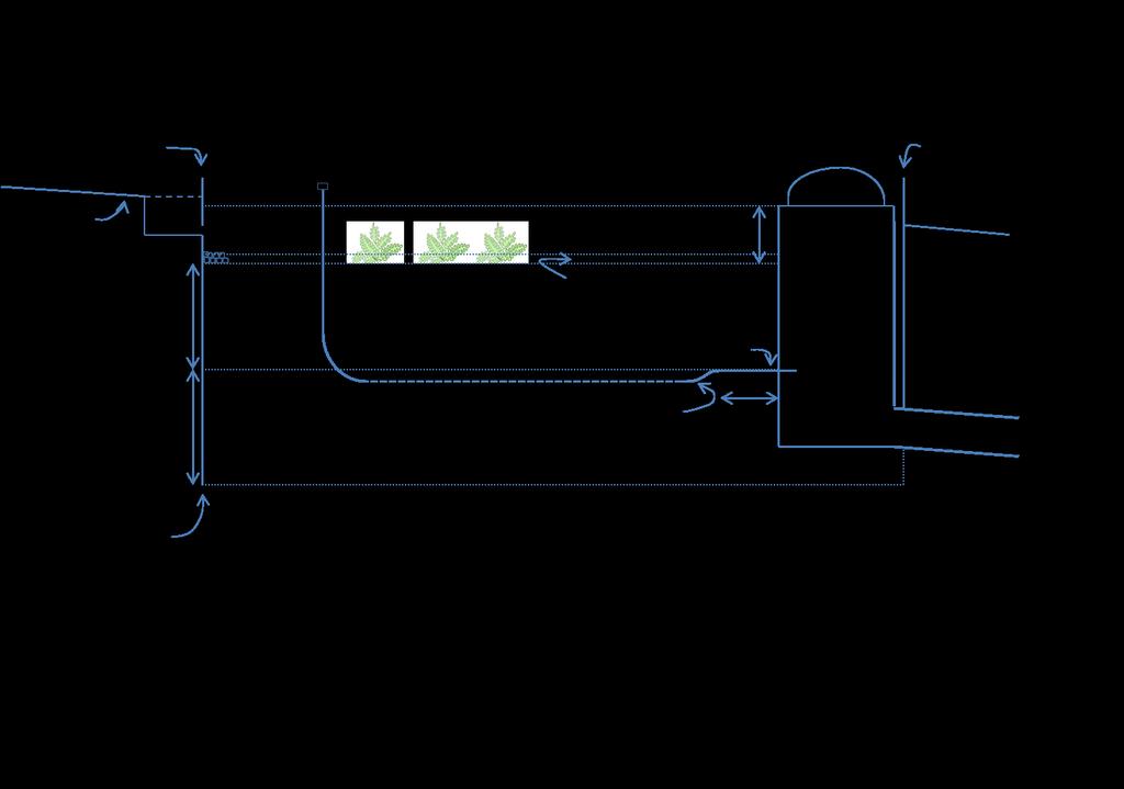
13 BASMAA The site design and landscape design must integrate the functionality of bioretention facilities and other stormwater features into the aesthetic and functional values of the project. Typical design issues include edges and transitions to allow runoff to flow from sidewalks and paved areas into bioretention facilities, dissipation of energy gained by runoff flowing down slopes, planting and irrigation of bioretention facilities, and integration of berms, fences, and walls in or near bioretention facilities. Chapter 4 includes design suggestions and tips. The submitted construction documents should include the Construction Checklist to assist the plan checker to cross-reference the SCP features with the plan sheets that show how the features have been executed. Appendix B is an inspection schedule and checklist for construction of bioretention facilities. 7: Transfer Maintenance Responsibility Following construction and a recommended maintenance and warranty period formally transfer maintenance responsibility to the owner or operator of the project, who will maintain the facilities in perpetuity. In the case of a residential subdivision, this may be a homeowners association, if that arrangement has been approved by your municipality. Set overflow inlets at the proper elevation so the surface of the bioretention facility floods as intended. 6: Construct the Project Careful construction of bioretention facilities, coordinated with the building of the development, will help ensure the facilities function as intended and will also minimize future maintenance problems. Items to check during construction include: Avoid compaction of native soils around where bioretention facilities will be constructed. Closely follow design elevations. Grade parking lots, driveways, and streets to promote evenly distributed sheet flow into bioretention facilities. Set overflow inlets at the proper elevation so the surface of the bioretention facility floods as intended. Figure 2.1. Bioretention Facility. The NPDES permit specifies the use of, and design criteria for, bioretention facilities to treat stormwater. POST-CONSTRUCTION MANUAL JULY 2014
14
15 CHAPTER PREPARING A STORMWATER CONTROL PLAN FOR A REGULATED PROJECT Objectives Your Stormwater Control Plan (SCP) for a Regulated Project must demonstrate your project incorporates site design measures and treatment facilities (typically bioretention facilities) that will: Minimize imperviousness. Retain or detain stormwater. Slow runoff rates. Reduce pollutants in post-development runoff. In particular, you will need to show all runoff from impervious areas is either dispersed to landscape or routed to a properly designed LID treatment facility. A complete and thorough SCP will enable municipal development review staff to verify your project complies with these requirements. It is strongly recommended you retain a design professional familiar with the requirements. Contents Your SCP will consist of a report and an exhibit. Municipal staff will use the Stormwater Control Plan Checklist (page 3-2) to evaluate the completeness of your Plan. Step by Step Plan and design your stormwater controls integrally with the site plan and landscaping for your project. This strategy requires you invest in early and ongoing coordination among project architects, landscape architects, and civil engineers. However, it can pay big dividends in a cost-effective, aesthetically pleasing design and by avoiding design conflicts later. Your initial, conceptual design for the project should include site drainage. This should include identifying areas where runoff can be dispersed and/or the location and approximate size of stormwater treatment and flow-control facilities. Follow these nine steps to complete your SCP. Step 1: Project Information Step 2: Opportunities and Constraints Step 3: Conceptual Site Design Step 4: Calculations and Documentation Step 5: Design Details Step 6: Source Controls Step 7: Maintenance Step 8: Construction Checklist Step 9: Certification Appendix D is a template containing an example outline. An example SCP is in Appendix E. Plan and design your stormwater controls integrally with the site and landscaping for your project. POST-CONSTRUCTION MANUAL JULY 2014
16 PREPARING A STORMWATER CONTROL PLAN Stormwater Control Plan Checklist Contents of Exhibit Existing natural hydrologic features (depressions, watercourses, wetlands, riparian corridors, relatively undisturbed areas) and significant natural resources. Existing and proposed site drainage network and connections to drainage off-site. Proposed design features and surface treatments used to minimize imperviousness and reduce runoff. Entire site divided into separate Drainage Management Areas (DMAs). Each DMA has a unique identifier and is characterized as self-retaining (zero-discharge), self-treating, or draining to a bioretention facility. Proposed locations and footprints of bioretention facilities. Potential pollutant source areas, including loading docks, food service areas, refuse areas, outdoor processes and storage, vehicle cleaning, repair or maintenance, fuel dispensing, equipment washing, etc. listed in Appendix A. Contents of Report Narrative analysis or description of site features and conditions that constrain, or provide opportunities for, stormwater control. Narrative description of site design characteristics that protect natural resources. Narrative description and/or tabulation of site design characteristics, building features, and pavement selections that reduce imperviousness of the site. Tabulation of proposed pervious and impervious area, showing self-treating areas, self-retaining areas, areas draining to self-retaining areas, and areas tributary to each bioretention facility. Preliminary designs, including calculations, for each bioretention facility. Elevations should show sufficient hydraulic head for each bioretention facility. Tabulation of pollutant sources from the list in Appendix A and for each source, the corresponding source control measure(s). General maintenance requirements for bioretention facilities Means by which facility maintenance will be financed and implemented in perpetuity. Statement accepting responsibility for interim operation & maintenance of facilities. Stormwater Construction Checklist. Certification by professional civil engineer, architect, or landscape architect (if required by local agency). POST-CONSTRUCTION MANUAL JULY 2014
17 BASMAA 1: Project Information Enter the following into the Project Data Form in the SCP Template: Project Name/Number Application Submittal Date Project Location Applicant Contact Information Project Phase Project Type and Description Project Site Area (square feet) Total New or Replaced Impervious Surface Area Total Pre-Project Impervious Surface Area Total Post-Project Impervious Surface Area 2: Opportunities and Constraints The following information will help you determine the best stormwater control design for your development site: Existing natural hydrologic features, including natural areas, wetlands, marshes, watercourses, seeps, springs, and areas with significant trees. Site topography and drainage, including the contours of slopes, the general direction of surface drainage, local high or low points or depressions, and any outcrops or other significant geologic features. Zoning, including setbacks and minimum landscaping requirements and open space. Soil types, including hydrologic soil groups, and depth to groundwater. Prepare a brief narrative describing site opportunities and constraints. Opportunities might include low areas, oddly configured or otherwise unbuildable areas, setbacks, easements, or buffers (which may sometimes accommodate bioretention facilities) and differences in elevation (which can provide hydraulic head). Constraints might include impermeable soils, high groundwater, groundwater pollution or contaminated soils, steep slopes, geotechnical instability, high-intensity land use, heavy pedestrian or vehicle traffic, or safety concerns. 3. Conceptual Site Design Optimize the site layout. Apply the following design principles: Define the development envelope and protected areas, identifying areas that are most suitable for development and areas that should be left undisturbed. Limit grading; preserve natural landforms and drainage patterns. Set back development from creeks, wetlands, and riparian habitats to the maximum degree possible and at minimum, as required by local ordinances. Concentrate development on portions of the site with less permeable soils and preserve areas that can promote infiltration. Preserve significant trees (as defined by the local jurisdiction). Limit paving and roofs. Where possible, design compact, taller structures, narrower and shorter streets and sidewalks, smaller parking lots (fewer stalls, smaller stalls, and more efficient lanes), and indoor or underground parking. Examine the site layout and circulation patterns and identify areas On flat sites, it usually works best to intersperse self-retaining areas and bioretention facilities throughout the site. POST-CONSTRUCTION MANUAL JULY 2014
18 PREPARING A STORMWATER CONTROL PLAN where landscaping or planter boxes can be substituted for pavement. Use pervious pavements where possible. Inventory paved areas and identify locations where permeable pavements, such as crushed aggregate, turf block, unit pavers, pervious concrete, or pervious asphalt can be substituted for impervious concrete or asphalt paving. Pervious pavements are most applicable where native soils are permeable. On site with clay soils, it may still be possible to use turf block for emergency access lanes and overflow parking or to use unit pavers or pervious pavement with a sufficiently deep and well-drained base course. Direct drainage to landscaped areas. There are two options for handling runoff from impervious areas: Disperse runoff to lawns or landscaping. Limit the ratio of impervious to pervious area to 2:1 maximum. Pervious areas must be relatively flat, and the surface should be graded to a slightly concave surface to create a self-retaining area. Sites in densely urbanized areas are often too constrained to implement this option. Route runoff to bioretention facilities. The bioretention areas should have a surface area of at least 4% of the tributary impervious area. Bioretention facilities may be configured in free-form fashion as rain gardens or in linear fashion as swales. Facilities located on elevated plazas may be configured as planter boxes. See Chapter 4 for design information on selfretaining areas and bioretention facilities. Tips for Conceptual Drainage Design. In clay soils, bioretention facilities must be underdrained. A bioretention facility requires three to four feet of head from inlet to underdrain outlet, which can be connected to an underground storm drain or daylighted. On flat sites, it usually works best to intersperse self-retaining areas and bioretention facilities throughout the site. Grade streets, parking lots, and driveways to sheet flow runoff directly into the landscaped areas. Use gutters, rather than underground pipes, to convey runoff longer distances. On sloped sites, it may work better to collect runoff from roofs and pavement in conventional catch basins and pipe it to downslope bioretention facilities. Use the head from roof downspouts by connecting leaders all the way to landscaping or bioretention facilities. Where necessary, bubble-ups can be used to disperse piped runoff. Siting bioretention facilities. Facilities should be publicly accessible for inspection and maintenance. In commercial, mixed-use, and multi-family developments, facilities can be located in parking medians, parking islands, street setbacks, side and rear setbacks, and other landscaped areas. In residential subdivisions, the most practical strategy is to drain the lots to the street in the conventional manner, and then drain the street to a bioretention area. It may be most advantageous to create a separate parcel owned in common, which can double as a landscape amenity or a park. (This is one reason why it is important to plan stormwater treatment and flow-control before drawing subdivision lot lines.) Facilities in back or side yards should be avoided. If facilities are located on individual lots, prospective buyers may find undesirable the necessary legal POST-CONSTRUCTION MANUAL JULY 2014
19 BASMAA restrictions on what they can do with those facilities. Other types of treatment facilities. Bioretention facilities are generally suitable for the Bay Area s modestly sized developments, clay soils, and setback requirements. Bioretention facilities sized to a minimum 4% of tributary impervious area can typically be fit into parking medians, street setbacks, foundation plantings, and other landscaping features without significantly altering the uses of the site. Further, bioretention facilities are relatively easy to maintain, provide aesthetic appeal, attenuate peak flows, and are quite effective at removing pollutants, including pollutants associated with very fine particulates in rain and atmospheric dust. Proposed alternatives to bioretention facilities meeting the criteria in Chapter 4 must show the ability to achieve: Equal or greater amount of runoff infiltrated or evapotranspired Equal or lower pollutant concentrations in runoff that is discharged after biotreatment Equal or greater protection against shock loadings and spills Equal or better accessibility and ease of inspection and maintenance. In some cases, it is very difficult to accommodate bioretention facilities on smaller, densely developed sites. Tree-box-type biofilters or in-vault media filters may be used to meet treatment requirements in the following circumstances: Projects that create or replace an acre or less of impervious area and are located in a locally designated pedestrian-oriented commercial district, and have at least 85% of the entire project site covered by permanent structures Facilities receiving runoff solely from existing (pre-project) impervious areas. Historic sites, structures, or landscapes that cannot alter their original configuration without compromising their historic integrity. The proposed tree-box-type biofilters or invault media filters must meet the Technical Criteria for Non-LID Treatment Facilities posted on the BASMAA website. 4. Calculations and Documentation Your SCP must include an Exhibit showing the entire site divided into Drainage Management Areas (DMAs) and the locations and approximate sizes of bioretetention facilities. Each should be clearly labeled so the Exhibit can be cross-referenced to the text and tables in the report. The report will include a brief description of each DMA and each bioretention facility and tabulated calculations. Chapter 4 includes a detailed procedure for documenting your design and showing your bioretention facilities meet the minimum sizing requirements. 5. Bioretention Design Criteria Design criteria in Chapter 4 will assist you to plan for construction of bioretention facilities as part of your project. The criteria that apply to your planned facilities should be summarized in your SCP. Anticipated exceptions to the design criteria should be noted. POST-CONSTRUCTION MANUAL JULY 2014
. Begin by identifying which of the listed sources are associated with your project.")
20 PREPARING A STORMWATER CONTROL PLAN 6. Source Controls Your SCP must identify and describe any potential pollutant sources that will be created or expanded as part of the development project. Review the Pollutant Sources/Source Control Checklist (Appendix A). Begin by identifying which of the listed sources are associated with your project. Then, create a table in the format shown in Table 3-1. Enter each identified source in the left-hand column. Then add the corresponding structural source controls from the Pollutant Sources/Source Control Checklist into the center column of your table. In a narrative, explain any special features, materials, or methods of construction that will be used to implement these permanent, structural source controls. To complete your table, refer once again to the Pollutant Sources/Source Control Checklist (Appendix A, Column 4). List the operational source controls corresponding to the sources you ve identified into the righthand column of your table. These controls should be implemented as long as the identified activities (sources) continue at the site. These controls may be required as a condition of a use permit or other revocable discretionary approval for uses of the site. Figure 3.1. Roofed and bermed refuse area. 7. Treatment Facility Maintenance In your SCP, specify the means by which maintenance of your bioretention facilities will be financed and implemented in perpetuity. For commercial, mixed-use or multifamily developments, maintenance responsibility may be assigned to a management entity that will be responsible for keeping up the buildings and grounds. Your O&M Plan, to be submitted later (see Chapter 5), will need to specify how maintenance will be funded and budgeted. Typically, the entity assuming responsibility for maintenance will need to Table 3.1. Format for Tabulating Potential Pollutant Sources and Source Controls Potential Source of Runoff Pollutants Structural Source Control BMPs Operational Source Control BMPs POST-CONSTRUCTION MANUAL JULY 2014
21 BASMAA execute a Stormwater Management Facilities Agreement, which runs with the land and provides for periodic inspections and reporting at the facility owner s expense. For residential subdivisions, consult with municipal staff, then detail the planned arrangements in your Stormwater Control Plan. Include, as available and applicable, information about joint ownership of parcels where bioretention facilities are to be located, about incorporating a homeowners association, about provisions to be incorporated in Covenants, Conditions, and Restrictions, and other relevant information. Include in your SCP the following statement: The applicant accepts responsibility for interim operation and maintenance of stormwater treatment and flow-control facilities until such time as this responsibility is formally transferred to a subsequent owner. A complete and detailed list of maintenance and inspection requirements, including inspection frequencies, will be required in your O&M Plan. Your O&M plan must also include detailed documentation of how your facilities are constructed. For this stage, include in your Stormwater Control Plan a summary of the general maintenance requirements for your bioretention facilities. You will find example maintenance requirements in Chapter Construction Checklist Include in your Stormwater Control Plan a Construction Checklist following the format in Table 3-2 below. Complete the first two columns in the checklist, listing each stormwater source control and treatment measure identified in the plan and identifying the page number where it appears. Later, cut-and-paste the same table into your construction documents. Complete the rightmost column, listing the sheet number(s) where the same measure is shown on the construction plans. 9. Certification Include the following statement by a licensed civil engineer, architect, or landscape architect: The preliminary design of stormwater treatment facilities and other stormwater pollution control measures in this Stormwater Control Plan are in accordance with the current edition of the BASMAA Post- Construction Manual. Table 3.2. Format for Stormwater Construction Checklist Page Number in Stormwater Control Plan Source Control or Treatment Control Measure Plan Sheet # POST-CONSTRUCTION MANUAL JULY 2014
22
23 CHAPTER DOCUMENTING YOUR LID DESIGN NPDES Compliance and LID The following design and documentation procedure facilitates rapid and thorough evaluation of a LID design for compliance with the NPDES permit requirements for a Regulated Project. The procedure involves dividing the site into Drainage Management Areas (DMAs), tracking the drainage from each DMA, and ensuring bioretention facilities receiving that drainage are adequately sized to treat the runoff. Bioretention facilities are sized at 4% of the equivalent tributary impervious area, as specified in the NPDES permit. This ratio, or sizing factor, greatly simplifies making and checking calculations. Step-by-Step The procedure requires the following steps: 1. Delineate DMAs. 2. Identify DMA types and runoff factors. 3. Select and lay out bioretention facilities. 4. Calculate the minimum area (footprint) of each bioretention facility. 5. Repeat as necessary until the available area exceeds the minimum area for each bioretention facility. 1: Delineate DMAs Drainage Management Areas (DMAs) are portions of a project site that drain to a common point. Each DMA must contain only one type of surface (e.g., either landscaped or impervious). In your SCP Exhibit, lines delineating DMAs will generally follow roof ridges and grade breaks. It is advantageous to first prepare a base map using the project grading plan and roof plan, and then delineate the DMAs. This helps ensure your SCP is consistent with the site plan, landscaping plan, and architectural plans. There are four types of DMAs: Self-treating areas Self-retaining areas Areas draining to self-retaining areas Areas draining to a bioretention facility Self treating areas are landscaped or turf areas that do not drain to bioretention facilities, but rather drain directly off site or to the storm drain system. Examples include upslope undeveloped areas that are ditched and drained around a development and grassed slopes that drain directly to a street or storm drain. In general, self-treating areas include no impervious areas, unless the impervious area is very small (5% or less) relative to the receiving pervious area and Runoff from impervious areas, such as roofs, can be managed by routing it to selfretaining pervious areas. The maximum ratio is 2 parts impervious area for every 1 part pervious area. POST-CONSTRUCTION MANUAL JULY 2014
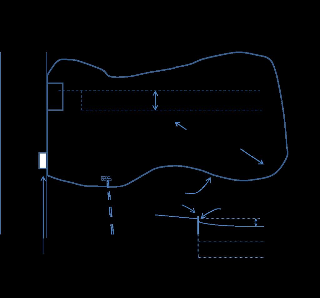
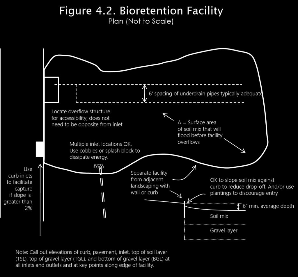
24 DOCUMENTING YOUR LID DESIGN slopes are gentle enough to ensure runoff will be absorbed into the vegetation and soil. Self-retaining areas are used where, because of site layout or topography, it is not possible to drain entirely pervious areas offsite separately (as with a self-treating area). The technique works best on flat, heavily landscaped sites. To create self-retaining turf and landscape areas in flat areas or on terraced slopes, berm the area or depress the grade into a concave cross-section so that these areas will retain the first inch of rainfall. Specify slopes, if any, toward the center of the pervious areas. Inlets of area drains, if any, should be set 3 inches or more above the low point to allow ponding. Areas draining to self-retaining areas. Runoff from impervious areas, such as roofs, can be managed by routing it to self-retaining pervious areas. The maximum ratio is 2 parts impervious area for every 1 part pervious area. The drainage from the impervious area must be directed to and dispersed within the pervious area, and the entire area must be designed to retain an inch of rainfall without flowing off-site. For example, if the maximum ratio of 2 parts impervious area into 1 part pervious area is used, then the pervious area must be graded concave or bermed so that 3 inches of water over its surface are absorbed before overflowing to an off-site drain. Prolonged ponding is a potential problem at higher impervious/pervious ratios. In your design, ensure that the pervious areas soils can handle the additional run-on and are sufficiently well-drained. Areas draining to a bioretention facility. These areas are used to calculate the required size of the bioretention facility. Two or more DMAs can drain to the same bioretention facility. However, a particular DMA can only drain to one bioretention facility. Where possible, design site drainage so only impervious roofs and pavement drain to bioretention facilities. This yields a simpler, more efficient design and also helps protect bioretention facilities from becoming clogged by sediment. 2. Tabulate DMAs For each DMA, determine whether it will be self-treating, self-retaining, drains to a selfretaining area, or drains to a bioretention facility. Group the DMAs by type. For each DMA, find and tabulate the area, post-project surface, and corresponding runoff factor. Use the runoff factors in Table Lay Out Bioretention Facilities From your conceptual drainage design (see Chapter 3) identify the locations and footprint of bioretention facilities. Design criteria for bioretention facilities are at the end of this chapter. Once you have laid out the bioretention facilities, calculate the square footage you have set aside for each bioretention facility. Then, recalculate the square footage of your DMAs to omit the square footage now dedicated to bioretention facilities. 4. Calculate minimum footprints The minimum area for each bioretention facility is found by summing up the contributions of each tributary DMA adjusted using the runoff factors in Table 4-1 and multiplying by the sizing factor of POST-CONSTRUCTION MANUAL JULY 2014
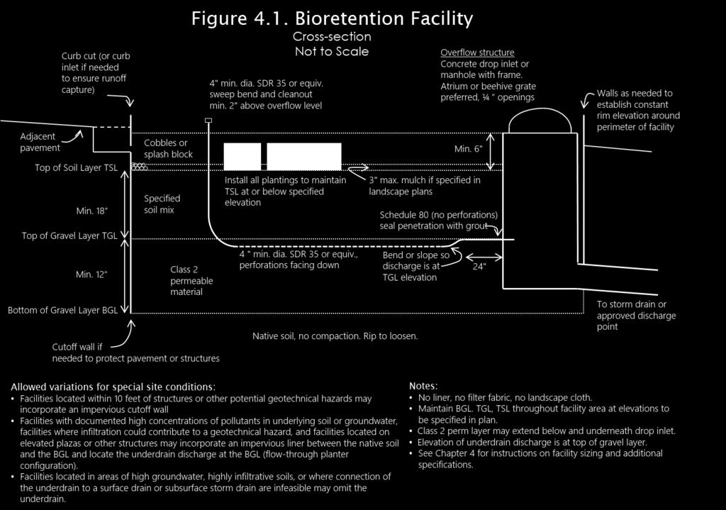
25 BASMAA Table 4-5 extends the tabulation of DMAs draining to bioretention facilities to a calculation of the required minimum area of the receiving bioretention facility. Complete Table 4-5 for each bioretention facility. 5. Iterate until area is adequate After computing the minimum bioretention facility size using Steps 1 4, review the site plan to determine if the reserved space for the facility is sufficient. If so, the planned facilities will meet the NPDES permit sizing requirements. If not, revise your plan accordingly. Revisions may include: Reducing the overall imperviousness of the project site. Changing the grading and drainage to redirect some runoff toward other bioretention facilities which may have excess capacity. Making tributary landscaped DMAs selftreating or self-retaining. Expanding the bioretention facility surface area. Bioretention facility design criteria Layout. Bioretention facilities may be of any shape. However, each layer must designed and built flat and level. The following must have consistent elevations throughout the facility: bottom of excavation/gravel layer (BGL) top of gravel storage layer (TGL) top of soil layer (TSL) rim of facility reservoir See Figures 4-1 and 4-2 and the checklist in Appendix B. The facility must be designed to fill up like a bathtub. This rule ensures all the storage is used during intense rainfall, prevents short-circuiting, and avoids erosion of the soil mix. The surface reservoir should be level and circumscribed by a rigid boundary such as a concrete curb, masonry, or landscape timbers. To address concerns about a trip hazard, or to achieve a softer visual effect, soil mix and/or mulch may be gently mounded against the rigid edge. Plantings can be selected and arranged to discourage entry. Gravel layer. Class 2 permeable, Caltrans specification F(3), is recommended. Drain rock or other granular material may be used; however, a membrane layer of pea gravel or other intermediate-sized material should cover the top of the gravel layer to prevent movement of fines from the soil layer into the interstices of the gravel layer. Do not use filter fabric for this purpose, as it tends to clog. Planting Medium. A mixture of sand (60%- 70%) and compost (30%-40%) should be used. The specification developed by the Bay Area Stormwater Management Agencies Association (BASMAA) is recommended. Underdrain. Use minimum 4" dia. PVC SDR 35 or equivalent, perforated pipe, installed with the holes facing down. The underdrain itself may be embedded in the gravel layer; the discharge elevation (typically, where the underdrain is connected to the overflow structure) is critical and must be no lower than the top of the gravel layer. Provide a threaded, capped cleanout connected by a sweep bend. POST-CONSTRUCTION MANUAL JULY 2014
26 DOCUMENTING YOUR LID DESIGN Table 4.1. Runoff Factors for small storms Roofs and paving 1.0 Landscaped areas 0.1 Bricks or solid pavers grouted 1.0 Bricks or solid pavers on sand base see criteria on p Pervious concrete or asphalt see criteria on p Turfblock or gravel see criteria on p Open or porous pavers see criteria on p Table 4.2. Format for Tabulating Self-Treating Areas DMA Name Area (square feet) Table 4.3. Format for Tabulating Self-Retaining Areas DMA Name Area (square feet) Table 4.4. Format for Tabulating Areas Draining to Self-Retaining Areas DMA Name Area (square feet) Post-project surface type Runoff factor Receiving selfretaining DMA Receiving selfretaining DMA Area (square feet) Table 4.5. Format for Tabulating Areas Draining to Bioretention Facilities and Calculating Minimum Bioretention Facility Size DMA Name DMA Area (square feet) Postproject surface type DMA Runoff factor DMA Area runoff factor Facility Name Sizing factor Total> 0.04 Minimum Facility Area (SF) Proposed Facility Area (SF) POST-CONSTRUCTION MANUAL JULY 2014
27 BASMAA Plantings and mulch. See Appendix F. Many bioretention facilities incorporate native plants in an attractive garden setting, achieving low maintenance costs, low water demand, and maximum habitat value. However, combined uses, including active uses on turf or mulch, may be appropriate for part or all of a bioretention facility. Select a plant palette to tolerate fast-draining soils and the microclimate specific to the facility location. The soil surface will be inundated briefly and rarely (for a few hours on possibly up to 5 occasions during a wet winter, but typically less frequently) but otherwise dry unless irrigated. Consider the facility s relationship to existing and proposed buildings and the resulting exposure to sun, heat, shade, and wind. The following problem conditions should be avoided when developing a planting plan: Overly dense plantings that, after growing in, prevent flow into and through the surface reservoir Aggressive roots that block inflow or percolation Invasive weeds Plants that need fertilizer or irrigation consider site-wide allowances under any water efficient landscape local ordinances. Trees and large shrubs installed in bioretention facilities are susceptible to blowing over before roots are established. They should be staked securely. Three stakes per tree are recommended at windy sites. Aged mulch, also called compost mulch, reduces the ability of weeds to establish, keeps the soil mix moist, and replenishes soil nutrients. Compared to bark mulch, aged mulch has somewhat less tendency to float into overflow inlets during intense storms. Irrigation. Because the specified soil mix is fast-draining, bioretention facilities may need to be irrigated more than once a day. Irrigation controls should allow separate control of times and durations of irrigation for bioretention facilities vs. other landscape areas. Smart irrigation controllers are strongly encouraged and may be required by local ordinances or codes. Available controllers may access weather stations, use sensors to measure soil temperature and moisture, and allow input of soil types, plant types, root depth, light conditions, slope, and rainfall. Drip emitters are strongly recommended over spray irrigation. Use multiple, lower-flow (0.5 to 2 gallons per hour) emitters two to four emitters for perennials, ground covers, and bunchgrasses; four to six emitters for larger shrubs and trees. Signage. If required by your local agency, include a sign. Signs should be visible to site users and to maintenance personnel. Avoid design conflicts. Review your bioretention design for the following: Facilities are represented in architectural and landscape renderings. Elevations all around each facility are consistent with grading, drainage, and paving plans, and with architectural plans. Facilities do not interfere with circulation or with pedestrian access between parking areas and building entrances. Bioretention facilities are shown in landscape plans, and a suitable plant palette has been chosen. POST-CONSTRUCTION MANUAL JULY 2014
28 DOCUMENTING YOUR LID DESIGN Cable vaults, phone vaults, electrical boxes, and other utility boxes are accommodated in designated locations outside the bioretention facilities. Criteria for Pervious Pavements No erodible areas should drain on to pervious pavement. A base course of open-graded crushed stone must be deep enough to retain rainfall (3" is adequate) and support design loads (more depth may be required). The subgrade must be uniform and slopes not so steep that the subgrade is prone to erosion. Subgrade compaction must be minimal. If a subdrain is included (not recommended), the outlet elevation must be 3" or more above the bottom of the base course. Granular pavements and unit pavers require a rigid edge to prevent movement. Solid unit pavers, if used, are set in sand or gravel with minimum 3/8 inch gaps between the pavers, and joints are filled with an opengraded aggregate free of fines. Permeable concrete or porous asphalt must be installed by industry-certified professionals according to vendor recommendations. Selection and location of pavements must incorporate Americans with Disabilities Act requirements (if applicable), site aesthetics, and uses. POST-CONSTRUCTION MANUAL JULY 2014
29 POST-CONSTRUCTION MANUAL JULY 2014
30 POST-CONSTRUCTION MANUAL JULY 2014
31 CHAPTER PREPARING YOUR OPERATION & M AINTENANCE PLAN Introduction As required by the statewide Phase II municipal NPDES stormwater permit, Permittees must verify provisions have been made for maintenance of the facilities in perpetuity. Typically this verification is accomplished by executing and recording an agreement that runs with the land. The agreement provides the municipality a right of access for inspections and requires the owner to conduct a maintenance inspection at least annually and retain a record of the inspection. If maintenance is not adequate, the municipality may conduct any maintenance or repairs needed and bill the owner to recover costs. The agreement is binding on future owners of the entire property or any subdivided portion of the property. Contact the local agency regarding a template for or model provisions of this agreement. When bioretention facilities are located in a privately owned common area, such as street or landscaped area within a residential subdivision, the joint responsibilities of the property owners must be spelled out in covenants, conditions, and restrictions (CC&Rs). The applicant s O&M Plan must address the specific drainage patterns and treatment facilities on the development site. The municipality may require that the O&M Plan be referenced in the agreement or attached as an exhibit. The O&M Plan is used to plan, direct, and record maintenance of the bioretention facilities. The O&M Plan is kept on-site, and a copy maintained at municipal offices. Updated information, including contact information, must be provided to the municipality whenever a property is sold and whenever designated individuals or contractors change. Step by Step Follow these five steps to prepare your bioretention facilities O&M Plan. Step 1: Designate Responsible Individuals Step 2: Describe the Facilities Step 3: Document the Facilities As Built Step 4: Schedule Maintenance Activities Step 5: Compile the Plan 1. Responsible Individuals. Identify the following individuals: Person who will have direct responsibility for the maintenance of stormwater controls, maintain self-inspection records, and sign 14 JULY POST-CONSTRUCTION MANUAL
32 OPERATION AND MAINTENANCE OF FACILITIES Municipalities will typically require a draft Operations and Maintenance Plan be submitted when building permits are applied for or even before. any correspondence with the municipality regarding the inspections. Employees or contractors who will report to the designated contact and are responsible for carrying out maintenance. Contact for response to problems, such as clogged drains or broken irrigation mains, that would require immediate response should they occur during off-hours. Describe the methods and schedule of initial training for staff or contractors regarding the purpose, mode of operation, and maintenance requirements for the facilities on the site. 2. Facilities to be Maintained Incorporate the following into the O&M Plan: Figures from your Stormwater Control Plan delineating the Drainage Management Areas on the site and showing the locations of the bioretention facilities. The tabulation of the Drainage Management Areas from the calculations in your Stormwater Control Plan. 3. Document Facilities As Built Include from the final construction drawings: Plans, elevations, and details of the bioretention facilities. If necessary, annotate the drawings with the designations used in the Stormwater Control Plan so it is clear which drawing refers to which facility. Construction details and specifications, including depths of sand or soil, compaction, pipe materials, and bedding. Location and layouts of inflow piping and piping to off-site discharge. Native soils encountered (e.g., sand or clay lenses beneath or near facilities). Municipalities will typically require a draft O&M Plan be submitted when building permits are applied for or even before. Changes made in the field during construction must be noted in the final Plan to be submitted following construction. 4. Schedule Maintenance Activities Scheduled the following activities to be completed at least annually. The frequency should be adjusted in response to the needs of each particular facility. Clean up. Remove any soil or debris blocking planter inlets or overflows. Remove trash that typically collects near inlets or gets caught in vegetation. Prune or cut back plants for health and to ensure flow into inlets and across the surface of the facility. Remove and replant as necessary. When replanting, maintain the design surface elevation and minimize the introduction of soil. Control weeds by manual methods and soil amendment. In response to problem areas or threatening invasions, corn gluten, white vinegar, vinegar-based products, or nonselective natural herbicides such as Burnout or Safer s Sharpshooter may be used. Add mulch. Aged mulch, also called compost mulch, reduces the ability of weeds to establish, keeps soil moist, and replenishes soil nutrients. Mulch is added from time to time as necessary to maintain a mulch layer thickness (some agencies require 3"). However, ensure the underlying soil surface 14 JULY POST-CONSTRUCTION MANUAL
33 BASMAA beneath the mulch layer is a minimum 6" below the overflow elevation, consistently throughout the surface area of the facility. In particular, ensure that the top of the mulch layer is below the facility overflow, so that as the facility fills during a major storm, the entire surface is become wetted before the overflow elevation is reached. Check signage. Remove graffiti and replace if necessary. Check irrigation, if any, to confirm it is adequate but not excessive. Landscape maintenance personnel should be aware of the following: Do not add fertilizer to bioretention facilities. Compost tea, available from various nurseries and garden supply retailers, may be applied at a recommended rate of 5 gallons mixed with 15 gallons of water per acre, up to two weeks prior to planting and once per year between March and June. Do not apply when temperatures are below 50 F or above 90 F or when rain is forecast in the next 48 hours. Do not use synthetic pesticides on bioretention facilities. Beneficial nematodes and non-toxic controls may be used. Acceptable natural pesticides include Safer products and Neem oil. Sample outline and format for an O&M Plan. Form for designating individuals responsible for operation and maintenance. Sample facility inspection and maintenance log. Sample contents of an inspector s report. Updates to the O&M Plan Updates can be made, and a copy transmitted to the municipality, at any time. In particular, contact information should be updated timely. The O&M Plan should be updated as needed at the time of the annual inspection. O&M Plans for Other Facility Types For other types of treatment facilities (see p. 3-5), discuss requirements for O&M plans with municipal staff. O&M plans for tree-box-type biofilters or in-vault media filters should incorporate the manufacturer s recommendations. 5. Compile the Plan Format plans to 8½" x 11" where possible to facilitate duplication, filing, and handling. Include the revision date in the footer of each page. Consider scanning the graphics and incorporating with the text in electronic files that can be backed up. The following resources at may help you when preparing your plan: 14 JULY POST-CONSTRUCTION MANUAL
34
35 APPENDIX A Pollutant Sources/Source Control Checklist
36 Appendix A. Stormwater Pollutant Sources/Source Controls Checklist How to use this worksheet (also see instructions on page 3-6 of the BASMAA Post-Construction Manual): 1. Review Column 1 and identify which of these potential sources of stormwater pollutants apply to your site. Check each box that applies. 2. Review Column 2 and incorporate all of the corresponding applicable Structural Source Control BMPs in your Stormwater Control Plan drawings. 3. Review Columns 3 and 4 and incorporate all of the corresponding applicable Structural Source Control BMPs and Operational Source Control BMPs in a table in your Stormwater Control Plan. Use the format shown in Table 3-1 on page 3-6 of the BASMAA Post-Construction Manual. Describe your specific BMPs in an accompanying narrative, and explain any special conditions or situations that required omitting BMPs or substituting alternative BMPs. IF THESE SOURCES WILL BE ON THE PROJECT SITE THEN YOUR STORMWATER CONTROL PLAN (SCP) SHOULD INCLUDE THESE SOURCE CONTROL BMPs Potential Sources of Runoff Pollutants Structural Source Controls Show on Stormwater Control Plan Drawings Structural Source Controls List in SCP Table and Narrative Operational Source Control BMPs Include in SCP Table and Narrative A. On-site storm drain inlets (unauthorized nonstormwater discharges and accidental spills or leaks) Locations of inlets. Mark all inlets with the words No Dumping! Flows to Bay or similar. Maintain and periodically repaint or replace inlet markings. Provide stormwater pollution prevention information to new site owners, lessees, or operators. See applicable operational BMPs in Fact Sheet SC-44, Drainage System Maintenance, in the CASQA Stormwater Quality Handbooks at Include the following in lease agreements: Tenant shall not allow anyone to discharge anything to storm drains or to store or deposit materials so as to create a potential discharge to storm drains. POST-CONSTRUCTION MANUAL A-1 DRAFT 14 JULY 2014
37 IF THESE SOURCES WILL BE ON THE PROJECT SITE THEN YOUR STORMWATER CONTROL PLAN (SCP) SHOULD INCLUDE THESE SOURCE CONTROL BMPs Potential Sources of Runoff Pollutants Structural Source Controls Show on Stormwater Control Plan Drawings Structural Source Controls List in SCP Table and Narrative Operational Source Control BMPs Include in SCP Table and Narrative B. Interior floor drains and elevator shaft sump pumps Show drains and pump locations State that interior floor drains and elevator shaft sump pumps will be plumbed to sanitary sewer. Inspect and maintain drains to prevent blockages and overflow. C. Interior parking garages Show drain locations State that parking garage floor drains will be plumbed to the sanitary sewer. Inspect and maintain drains to prevent blockages and overflow. D1. Need for future indoor & structural pest control Note building design features that discourage entry of pests. Provide Integrated Pest Management information to owners, lessees, and operators. POST-CONSTRUCTION MANUAL A-2 DRAFT 14 JULY 2014
38 IF THESE SOURCES WILL BE ON THE PROJECT SITE THEN YOUR STORMWATER CONTROL PLAN (SCP) SHOULD INCLUDE THESE SOURCE CONTROL BMPs Potential Sources of Runoff Pollutants Structural Source Controls Show on Stormwater Control Plan Drawings Structural Source Controls List in SCP Table and Narrative Operational Source Control BMPs Include in SCP Table and Narrative D2. Landscape/ Outdoor Pesticide Use/Building and Grounds Maintenance Show locations of native trees or areas of shrubs and ground cover to be undisturbed and retained. Show self-retaining landscape areas, if any. Show bioretention facilities. (See instructions in Chapter 4.) State that final landscape plans will accomplish all of the following. Preserve existing native trees, shrubs, and ground cover to the maximum extent possible. Design landscaping to minimize irrigation and runoff, to promote surface infiltration where appropriate, and to minimize the use of fertilizers and pesticides that can contribute to stormwater pollution. Maintain landscaping using minimum or no pesticides. See applicable operational BMPs in Fact Sheet SC-41, Building and Grounds Maintenance, in the CASQA Stormwater Quality Handbooks at Provide IPM information to new owners, lessees and operators. Where landscaped areas are used to retain or detain stormwater, specify plants that are tolerant of saturated soil conditions. Consider using pest-resistant plants, especially adjacent to hardscape. To insure successful establishment, select plants appropriate to site soils, slopes, climate, sun, wind, rain, land use, air movement, ecological consistency, and plant interactions. POST-CONSTRUCTION MANUAL A-3 DRAFT 14 JULY 2014
39 IF THESE SOURCES WILL BE ON THE PROJECT SITE THEN YOUR STORMWATER CONTROL PLAN (SCP) SHOULD INCLUDE THESE SOURCE CONTROL BMPs Potential Sources of Runoff Pollutants Structural Source Controls Show on Stormwater Control Plan Drawings Structural Source Controls List in SCP Table and Narrative Operational Source Control BMPs Include in SCP Table and Narrative E. Pools, spas, ponds, decorative fountains, and other water features. Show location of water feature and a sanitary sewer cleanout in an accessible area within 10 feet. If the local municipality requires pools to be plumbed to the sanitary sewer, place a note on the plans and state in the narrative that this connection will be made according to local requirements. See applicable operational BMPs in Fact Sheet SC-72, Fountain and Pool Maintenance, in the CASQA Stormwater Quality Handbooks at The sanitary sewer operator must be notified and a clean out identified when pools are to be drained to the sanitary sewer. F. Food service For restaurants, grocery stores, and other food service operations, show location (indoors or in a covered area outdoors) of a floor sink or other area for cleaning floor mats, containers, and equipment. On the drawing, show a note that this drain will be connected to a grease interceptor before discharging to the sanitary sewer. Describe the location and features of the designated cleaning area. Describe the items to be cleaned in this facility and how it has been sized to insure that the largest items can be accommodated. State maintenance schedule for grease interceptor POST-CONSTRUCTION MANUAL A-4 DRAFT 14 JULY 2014
40 IF THESE SOURCES WILL BE ON THE PROJECT SITE THEN YOUR STORMWATER CONTROL PLAN (SCP) SHOULD INCLUDE THESE SOURCE CONTROL BMPs 1 Potential Sources of Runoff Pollutants G. Refuse areas 2 Structural Source Controls Show on Stormwater Control Plan Drawings Show where site refuse and recycled materials will be handled and stored for pickup. See local municipal requirements for sizes and other details of refuse areas. If dumpsters or other receptacles are outdoors, show how the designated area will be covered, graded, and paved to prevent run-on and show locations of berms to prevent runoff from the area. Any drains from dumpsters, compactors, and tallow bin areas shall be connected to a grease removal device before discharge to sanitary sewer. 3 Structural Source Controls List in SCP Table and Narrative State how site refuse will be handled and provide supporting detail to what is shown on plans. State that signs will be posted on or near dumpsters with the words Do not dump hazardous materials here or similar. 4 Operational Source Control BMPs Include in SCP Table and Narrative State how the following will be implemented: Provide adequate number of receptacles. Inspect receptacles regularly; repair or replace leaky receptacles. Keep receptacles covered. Prohibit/prevent dumping of liquid or hazardous wastes. Post no hazardous materials signs. Inspect and pick up litter daily and clean up spills immediately. Keep spill control materials available on-site. See Fact Sheet SC-34, Waste Handling and Disposal in the CASQA Stormwater Quality Handbooks at H. Industrial processes. Show process area. If industrial processes are to be located on site, state: All process activities to be performed indoors. No processes to drain to exterior or to storm drain system. See Fact Sheet SC-10, Non-Stormwater Discharges in the CASQA Stormwater Quality Handbooks at POST-CONSTRUCTION MANUAL A-5 DRAFT 14 JULY 2014
41 IF THESE SOURCES WILL BE ON THE PROJECT SITE THEN YOUR STORMWATER CONTROL PLAN (SCP) SHOULD INCLUDE THESE SOURCE CONTROL BMPs Potential Sources of Runoff Pollutants Structural Source Controls Show on Stormwater Control Plan Drawings Structural Source Controls List in SCP Table and Narrative Operational Source Control BMPs Include in SCP Table and Narrative I. Outdoor storage of equipment or materials. (See rows J and K for source control measures for vehicle cleaning, repair, and maintenance.) Show any outdoor storage areas, including how materials will be covered. Show how areas will be graded and bermed to prevent run-on or run-off from area. Storage of non-hazardous liquids shall be covered by a roof and/or drain to the sanitary sewer system, and be contained by berms, dikes, liners, or vaults. Storage of hazardous materials and wastes must be in compliance with the local hazardous materials ordinance and a Hazardous Materials Management Plan for the site. Include a detailed description of materials to be stored, storage areas, and structural features to prevent pollutants from entering storm drains. Where appropriate, reference documentation of compliance with the requirements of programs for: Hazardous Waste Generation Hazardous Materials Release Response and Inventory California Accidental Release (CalARP) Aboveground Storage Tank Uniform Fire Code Article 80 Section 103(b) & (c) 1991 See the Fact Sheets SC-31, Outdoor Liquid Container Storage and SC-33, Outdoor Storage of Raw Materials in the CASQA Stormwater Quality Handbooks at Underground Storage Tank POST-CONSTRUCTION MANUAL A-6 DRAFT 14 JULY 2014
42 IF THESE SOURCES WILL BE ON THE PROJECT SITE THEN YOUR STORMWATER CONTROL PLAN (SCP) SHOULD INCLUDE THESE SOURCE CONTROL BMPs Potential Sources of Runoff Pollutants Structural Source Controls Show on Stormwater Control Plan Drawings Structural Source Controls List in SCP Table and Narrative Operational Source Control BMPs Include in SCP Table and Narrative J. Vehicle and Equipment Cleaning Show on drawings as appropriate: (1) Commercial/industrial facilities having vehicle/ equipment cleaning needs shall either provide a covered, bermed area for washing activities or discourage vehicle/equipment washing by removing hose bibs and installing signs prohibiting such uses. (2) Multi-dwelling complexes shall have a paved, bermed, and covered car wash area (unless car washing is prohibited on-site and hoses are provided with an automatic shut-off to discourage such use). If a car wash area is not provided, describe measures taken to discourage on-site car washing and explain how these will be enforced. Describe operational measures to implement the following (if applicable): Washwater from vehicle and equipment washing operations shall not be discharged to the storm drain system. Car dealerships and similar may rinse cars with water only. See Fact Sheet SC-21, Vehicle and Equipment Cleaning, in the CASQA Stormwater Quality Handbooks at (3) Washing areas for cars, vehicles, and equipment shall be paved, designed to prevent run-on to or runoff from the area, and plumbed to drain to the sanitary sewer. (4) Commercial car wash facilities shall be designed such that no runoff from the facility is discharged to the storm drain system. Wastewater from the facility shall discharge to the sanitary sewer, or a wastewater reclamation system shall be installed. POST-CONSTRUCTION MANUAL A-7 DRAFT 14 JULY 2014
43 IF THESE SOURCES WILL BE ON THE PROJECT SITE THEN YOUR STORMWATER CONTROL PLAN (SCP) SHOULD INCLUDE THESE SOURCE CONTROL BMPs Potential Sources of Runoff Pollutants Structural Source Controls Show on Stormwater Control Plan Drawings Structural Source Controls List in SCP Table and Narrative Operational Source Control BMPs Include in SCP Table and Narrative K. Vehicle/Equipment Repair and Maintenance Accommodate all vehicle equipment repair and maintenance indoors. Or designate an outdoor work area and design the area to prevent run-on and runoff of stormwater. Show secondary containment for exterior work areas where motor oil, brake fluid, gasoline, diesel fuel, radiator fluid, acid-containing batteries or other hazardous materials or hazardous wastes are used or stored. Drains shall not be installed within the secondary containment areas. Add a note on the plans that states either (1) there are no floor drains, or (2) floor drains are connected to wastewater pretreatment systems prior to discharge to the sanitary sewer and an industrial waste discharge permit will be obtained. State that no vehicle repair or maintenance will be done outdoors, or else describe the required features of the outdoor work area. State that there are no floor drains or if there are floor drains, note the agency from which an industrial waste discharge permit will be obtained and that the design meets that agency s requirements. State that there are no tanks, containers or sinks to be used for parts cleaning or rinsing or, if there are, note the agency from which an industrial waste discharge permit will be obtained and that the design meets that agency s requirements. In the Stormwater Control Plan, note that all of the following restrictions apply to use the site: No person shall dispose of, nor permit the disposal, directly or indirectly of vehicle fluids, hazardous materials, or rinsewater from parts cleaning into storm drains. No vehicle fluid removal shall be performed outside a building, nor on asphalt or ground surfaces, whether inside or outside a building, except in such a manner as to ensure that any spilled fluid will be in an area of secondary containment. Leaking vehicle fluids shall be contained or drained from the vehicle immediately. No person shall leave unattended parts or other open containers containing vehicle fluid, unless such containers are in use or in an area of secondary containment. POST-CONSTRUCTION MANUAL A-8 DRAFT 14 JULY 2014
44 IF THESE SOURCES WILL BE ON THE PROJECT SITE THEN YOUR STORMWATER CONTROL PLAN (SCP) SHOULD INCLUDE THESE SOURCE CONTROL BMPs 1 Potential Sources of Runoff Pollutants L. Fuel Dispensing Areas 2 Structural Source Controls Show on Stormwater Control Plan Drawings Fueling areas shall have impermeable floors (i.e., portland cement concrete or equivalent smooth impervious surface) that are: a) graded at the minimum slope necessary to prevent ponding; and b) separated from the rest of the site by a grade break that prevents run-on of stormwater to the maximum extent practicable. Fueling areas shall be covered by a canopy that extends a minimum of ten feet in each direction from each pump. [Alternative: The fueling area must be covered and the cover s minimum dimensions must be equal to or greater than the area within the grade break or fuel dispensing area 1.] The canopy [or cover] shall not drain onto the fueling area. 3 Structural Source Controls List in SCP Table and Narrative 4 Operational Source Control BMPs Include in SCP Table and Narrative The property owner shall dry sweep the fueling area routinely. See the Business Guide Sheet, Automotive Service Service Stations in the CASQA Stormwater Quality Handbooks at POST-CONSTRUCTION MANUAL A-9 DRAFT 14 JULY 2014
45 IF THESE SOURCES WILL BE ON THE PROJECT SITE THEN YOUR STORMWATER CONTROL PLAN (SCP) SHOULD INCLUDE THESE SOURCE CONTROL BMPs 1 Potential Sources of Runoff Pollutants M. Loading Docks 2 Structural Source Controls Show on Stormwater Control Plan Drawings Show the loading dock area, including roofing and drainage. Loading docks shall be covered and/or graded to minimize run-on to and runoff from the loading area. Roof downspouts shall be positioned to direct stormwater away from the loading area. Water from loading dock areas shall be drained to the sanitary sewer, or diverted and collected for ultimate discharge to the sanitary sewer. Loading dock areas draining directly to the sanitary sewer shall be equipped with a spill control valve or equivalent device, which shall be kept closed during periods of operation. Provide a roof overhang over the loading area or install door skirts (cowling) at each bay that enclose the end of the trailer. 3 Structural Source Controls List in SCP Table and Narrative 4 Operational Source Control BMPs Include in SCP Table and Narrative Move loaded and unloaded items indoors as soon as possible. See Fact Sheet SC-30, Outdoor Loading and Unloading, in the CASQA Stormwater Quality Handbooks at N. Fire Sprinkler Test Water Provide a means to drain fire sprinkler test water to the sanitary sewer. See the note in Fact Sheet SC-41, Building and Grounds Maintenance, in the CASQA Stormwater Quality Handbooks at POST-CONSTRUCTION MANUAL A-10 DRAFT 14 JULY 2014
46 IF THESE SOURCES WILL BE ON THE PROJECT SITE THEN YOUR STORMWATER CONTROL PLAN (SCP) SHOULD INCLUDE THESE SOURCE CONTROL BMPs Potential Sources of Runoff Pollutants Structural Source Controls Show on Stormwater Control Plan Drawings Structural Source Controls List in SCP Table and Narrative Operational Source Control BMPs Include in SCP Table and Narrative O. Miscellaneous Drain or Wash Water or Other Sources Boiler drain lines Condensate drain lines Rooftop equipment Drainage sumps Roofing, gutters, and trim. Other sources Show drain lines and drainage sumps Boiler drain lines shall be directly or indirectly connected to the sanitary sewer system and may not discharge to the storm drain system. Condensate drain lines may discharge to landscaped areas if the flow is small enough that runoff will not occur. Condensate drain lines may not discharge to the storm drain system. Rooftop equipment with potential to produce pollutants shall be roofed and/or have secondary containment. Any drainage sumps on-site shall feature a sediment sump to reduce the quantity of sediment in pumped water. Include controls for other sources as specified by local reviewer. If architectural copper is used, implement the following BMPs for management of rinsewater during installation: If possible, purchase copper materials that have been pre-patinated at the factory. If patination is done on-site, prevent rinse water from entering storm drains by discharging to landscaping or by collecting in a tank and hauling off-site. Consider coating the copper materials with an impervious coating that prevents further corrosion and runoff. Implement the following BMPs during routine maintenance: Prevent rinse water from entering storm drains by discharging to landscaping or by collecting in a tank and hauling offsite. P. Plazas, sidewalks, and parking lots. Show extent of permeable paving materials Sweep plazas, sidewalks, and parking lots regularly to prevent accumulation of litter and debris. Collect debris from pressure washing to prevent entry into the storm drain system. Collect washwater containing any cleaning agent or degreaser and discharge to the sanitary sewer not to a storm drain. POST-CONSTRUCTION MANUAL A-11 DRAFT 14 JULY 2014
47 APPENDIX B Bioretentiion Construction Inspection Checklist
48 This blank page incorporated to facilitate 2-sided copying.
49 Appendix B. Bioretention Facility Construction Inspection Checklist Layout (to be confirmed prior to beginning excavation) Square footage of the facility meets or exceeds minimum shown in Stormwater Control Plan Site grading and grade breaks are consistent with the boundaries of the tributary Drainage Management Area(s) (DMAs) shown in the Stormwater Control Plan Inlet elevation of the facility is low enough to receive drainage from the entire tributary DMA Locations and elevations of overland flow or piping, including roof leaders, from impervious areas to the facility have been laid out and any conflicts resolved Rim elevation of the facility is laid out to be level all the way around, or elevations are consistent with a detailed cross-section showing location and height of interior dams Locations for vaults, utility boxes, and light standards have been identified so that they will not conflict with the facility Facility is protected as needed from construction-phase runoff and sediment Excavation (to be confirmed prior to backfilling or pipe installation) Excavation conducted with materials and techniques to minimize compaction of soils within the facility area Excavation is to accurate area and depth Slopes or side walls protect from sloughing of native soils into the facility Moisture barrier, if specified, has been added to protect adjacent pavement or structures. Native soils at bottom of excavation are ripped or loosened to promote infiltration Overflow or Surface Connection to Storm Drainage (to be confirmed prior to backfilling with any materials) Overflow is at specified elevation No knockouts or side inlets are in overflow riser Overflow location selected to minimize surface flow velocity (near, but offset from, inlet recommended) Grating excludes mulch and litter (beehive or atrium-style grates with ¼" openings recommended) Overflow is connected to storm drain via appropriately sized piping Underground connection to storm drain/outlet orifice (to be confirmed prior to backfilling with any materials) Perforated pipe underdrain (PVC SDR 35 or approved equivalent) is installed with holes facing down Perforated pipe is connected to storm drain at specified elevation (typ. bottom of soil elevation) Cleanouts are in accessible locations and connected via sweep bends POST-CONSTRUCTION MANUAL B-1 14 JULY 2014
50 Drain Rock/Subdrain (to be confirmed prior to installation of soil mix) Rock is installed as specified, 12" min. depth. Class 2 permeable, Caltrans specification F(3) recommended Rock is smoothed to a consistent top elevation. Depth and top elevation are as shown in plans Slopes or side walls protect from sloughing of native soils into the facility No filter fabric is placed between the subdrain and soil mix layers Soil Mix Soil mix is as specified. Mix installed in lifts not exceeding 12" Mix is not compacted during installation but may be thoroughly wetted to encourage consolidation Mix is smoothed to a consistent top elevation. Depth of mix (18" min.) and top elevation are as shown in plans, accounting for depth of mulch to follow and required reservoir depth Irrigation Irrigation system is installed so it can be controlled separately from other landscaped areas. Smart irrigation controllers and drip emitters are recommended and may be required by local code or ordinance. Spray heads, if any, are positioned to avoid direct spray into outlet structures Planting Plants are installed consistent with approved planting plan, consistent with site water allowance Any trees and large shrubs are staked securely No fertilizer is added; compost tea may be used No native soil or clayey material are imported into the facility with plantings 1"-2" mulch may be applied following planting; mulch selected to avoid floating Final elevation of soil mix maintained following planting Curb openings are free of obstructions Final Engineering Inspection Drainage Management Area(s) are free of construction sediment and landscaped areas are stabilized Inlets are installed to provide smooth entry of runoff from adjoining pavement, have sufficient reveal (drop from the adjoining pavement to the top of the mulch or soil mix, and are not blocked Inflows from roof leaders and pipes are connected and operable Temporary flow diversions are removed Rock or other energy dissipation at piped or surface inlets is adequate Overflow outlets are configured to allow the facility to flood and fill to near rim before overflow Plantings are healthy and becoming established Irrigation is operable Facility drains rapidly; no surface ponding is evident Any accumulated construction debris, trash, or sediment is removed from facility Permanent signage is installed and is visible to site users and maintenance personnel POST-CONSTRUCTION MANUAL B-2 14 JULY 2014
51 APPENDIX C Stormwater Control Plan Template for Small Projects/Single-Family Homes
52 This blank page incorporated to facilitate 2-sided copying.
53 Stormwater Control Plan for Small Projects/Single-Family Homes Introduction The California State Water Resources Control Board reissued the Phase II NPDES Permit for Small Municipal Storm Sewer Systems (MS4s) in February As of June 30, 2015, development projects that create or replace 2,500 square feet* or more of impervious surface (roofs or pavement) must incorporate specified measures to reduce runoff. This requirement is part of municipalities comprehensive effort to reduce runoff pollution. Some municipalities may choose to implement the requirements earlier, and/or on projects that create or replace less than 2,500 square feet of impervious surface. It is fairly easy to achieve compliance with the stormwater requirements for small land development projects. Compliance for each project must be carefully documented. Please complete the following form and submit it as directed by municipal staff. In addition, staff will review your site plan to confirm that the following design strategies have been incorporated into your project: Limit disturbance of creeks and natural drainage features Minimize compaction of highly permeable soils Limit clearing and grading of native vegetation at the site to the minimum area needed to build the project, allow access, and provide fire protection Minimize impervious surfaces by concentrating development on the least-sensitive portions of the site, while leaving the remaining land in a natural undisturbed state *Projects that create or replace 5,000 square feet or more of impervious surface, except for detached singlefamily homes, require a comprehensive Stormwater Control Plan for Regulated Projects. Step-by-Step Instructions The steps are: 1. Fill out the Project Data Form (below) and select one or more runoff reduction measures. 2. Prepare a site plan or sketch. Specify and design the runoff reduction measures you will use to meet the stated minimum requirements. 3. Complete your submittal, which will include: Project Data Form Site Plan or Sketch Completed checklist for each Runoff Reduction Measure selected 14 JULY 2014 Page 1 of 8 BASMAA
54 Step 1: Project Data Form and Runoff Reduction Measure Selection Complete all fields. Project Name/Number Application Submittal Date [to be verified by municipal staff] Project Location [Street Address if available, or intersection and/or APN] Name of Owner or Developer Project Type and Description [Examples: Single Family Residence, Parking Lot Addition, Retail and Parking ] Total Project Site Area (acres) Total New or Replaced Impervious Surface Area (square feet) [Sum of impervious area that will be constructed as part of the project] Total Pre-Project Impervious Surface Area Total Post-Project Impervious Surface Area Runoff Reduction Measures Selected (Check one or more) 1. Disperse runoff to vegetated area 2. Pervious pavement 3. Cisterns or Rain Barrels 4. Bioretention Facility or Planter Box Step 2: Delineate impervious areas and locations of runoff reduction measures Delineate the impervious area. On a site plan or sketch, show the impervious area for example, a roof, or portion of a roof, or a paved area that will drain to your runoff reduction measure. Typically these delineations follow roof ridge lines or grade breaks. Alternatively, show the type and extent of pervious paving. An example sketch is attached. 14 JULY 2014 Page 2 of 8 BASMAA
55 Indicate the location and kind of runoff reduction measure you ve selected. At least one option, designed to manage runoff from some amount of impervious area or to avoid creating runoff is required. For each option selected, there is a brief checklist to confirm your design and your submittal meet minimum requirements. Step 3: Complete and submit your plan Consult with municipal staff about when and how to submit your Stormwater Control Plan. Runoff Reduction Options Option 1: Disperse runoff from roofs or pavement to vegetated areas. This is the simplest option. Downspouts can be directed to vegetated areas adjacent to buildings, or extended via pipes to reach vegetated areas further away. Paved areas can be designed with curb cuts, or without curbs, to direct flow into surrounding vegetation. On the site plan, show: Each impervious area from which runoff will be directed, and its square footage. The vegetated areas that will receive runoff, and the approximate square footage of each. If necessary, explain in notes on the plan how runoff will be routed from impervious surfaces to vegetated areas. Connecting a roof leader to a vegetated area. The head from the eave height makes it possible to route roof drainage some distance away from the building. Confirm the following standard specifications are met: Tributary impervious square footage in no instance exceeds twice the square footage of the receiving pervious area. Roof areas collect runoff and route it to the receiving pervious area via gutters and downspouts. Paved areas are sloped so drainage is routed to the receiving pervious area. Runoff is dispersed across the vegetated area (for example, with a splash block) to avoid erosion and promote infiltration. Vegetated area has amended soils, vegetation, and irrigation as required to maintain soil stability and permeability. Any drain inlets within the vegetated area are at least 3 inches above surrounding grade. 14 JULY 2014 Page 3 of 8 BASMAA

56 Option 2: Permeable Pavement This option can be easy to install and maintain, cost-effective, and can add aesthetic value to your project. Permeable pavements may include pervious concrete, pervious asphalt, porous pavers, crushed aggregate, open pavers with grass or plantings, open pavers with gravel, or solid pavers. Show on your site plan: Location, extent and types of pervious pavements. Confirm the following standard specifications are met: No erodible areas drain on to permeable pavement. Subgrade compaction is minimal. Reservoir base course is of open-graded crushed stone. Base depth is adequate to retain rainfall (3 inches is adequate) and support design loads (more depth may be required). No subdrain is included or, if a subdrain is included, outlet elevation is a minimum of 3 inches above bottom of base course. Subgrade is uniform and slopes are not so steep that subgrade is prone to erosion. Rigid edge is provided to retain granular pavements and unit pavers. Solid unit pavers, if used, are set in sand or gravel with minimum 3/8 inch gaps between the pavers. Joints are filled with an open-graded aggregate free of fines. Permeable concrete or porous asphalt, if used, are installed by industry-certified professionals according to the vendor s recommendations. Selection and location of pavements incorporates Americans with Disabilities Act requirements (if applicable), site aesthetics, and uses. 14 JULY 2014 Page 4 of 8 BASMAA
57 Option 3: Cisterns or Rain Barrels Use of cisterns or rain barrels to comply with this requirement is subject to municipality approval. Planning and Building Permits may be required for larger systems. Show on your site plan: Impervious areas tributary to each cistern or rain barrel. Location of each cistern or rain barrel. Confirm the following standard specifications are met: Rain barrels are sited at grade on a sound and level surface at or near gutter downspouts. Gutters tributary to rain barrels are screened with a leaf guard or maximum ½-inch to ¼-inchminimum corrosion-resistant metallic hardware fabric. Water collected will be used for irrigation only. Openings are screened with a corrosion-resistant metallic fine mesh (1/16 inch or smaller) to prevent mosquito harborage. Large openings are secured to prevent entry by children. Rain barrels and gutters are to be cleaned annually. The local mosquito and vector control district is informed of the installation. The district will be provided additional information and/or rights of entry if they request. 14 JULY 2014 Page 5 of 8 BASMAA
58 Option 4: Bioretention Facility or Planter Box An above-ground planter box may be appropriate if the development site lacks level landscaped areas for dispersion and pervious pavements are not practical. Planter boxes and bioretention facilities can treat runoff from impervious surfaces 25 times their area (sizing factor of 0.04). Detailed design guidance for bioretention facilities is in the Stormwater Technical Guide. Show on your site plan: Impervious areas tributary to the planter box. Location and footprint of planter box. Confirm the following standard specifications are met: Flow-through planter built into a hillside. Flows from the underdrain and overflow must be directed in accordance with local requirements. Reservoir depth is 4"-6" minimum. 18" depth soil mix with minimum long-term infiltration rate of 5"/hour. See for a list of soil mix suppliers. Surface area of soil mix is a minimum 0.04 times the tributary impervious area. Class 2 perm drainage layer 12" deep. No filter fabric. Perforated pipe (PVC SDR 35 or approved equivalent) underdrain with outlet located flush or nearly flush with planter bottom. Connection with sufficient head to storm drain or discharge point. Underdrain has a clean-out port consisting of a vertical, rigid, non-perforated PVC pipe, connected to the underdrain via a sweep bend, with a minimum diameter of 4" and a watertight cap. Overflow outlet connected to a downstream storm drain or approved discharge point. Planter is set level. Emergency spillage will be safely conveyed overland. Plantings are suitable to the climate, exposure, and a well-drained soil. Irrigation system with connection to water supply, on a separate zone. 14 JULY 2014 Page 6 of 8 BASMAA
59 Useful Resources The following references may be useful for design. Designs must meet the minimum standard specifications herein. BASMAA Post-Construction Manual. Start At the Source: Design Guidance Manual for Stormwater Quality. Bay Area Stormwater Management Agencies Association, Concrete Promotion Council of Northern California California Asphalt Pavement Association Interlocking Concrete Pavement Institute Porous Pavements, by Bruce K. Ferguson ISBN JULY 2014 Page 7 of 8 BASMAA


60 Example Sketch The example below illustrates the level of detail required. Not to Scale JULY 2014 Page 8 of 8 BASMAA
Example Stormwater Control Plan For a Residential Subdivision Project. Whispering Pines Lane Anytown, USA
 Example Stormwater Control Plan For a Residential Subdivision Project Whispering Pines Lane Anytown, USA December 2, 2015 XYZ Corporation Jane Jones, 707-555-1212 This example prepared by Dan Cloak Environmental
Stormwater Technical Guide
 Stormwater Technical Guide Compliance with Stormwater Post-Construction Requirements in Santa Barbara County Dan Cloak, Principal Dan Cloak Environmental Consulting January 9, 2014 Introduce yourself Name
Example Stormwater Control Plan For a Residential Subdivision Project. Whispering Pines Lane Anytown, USA. February 21, 2018
 Example Stormwater Control Plan For a Residential Subdivision Project Whispering Pines Lane Anytown, USA February 21, 2018 XYZ Corporation Jane Jones, 925-555-1212 This example prepared by Dan Cloak Environmental
S T O R M W A T E R T E C H N I C A L G U I D E F O R L O W I M P A C T D E V E L O P M E N T
 S T O R M W A T E R T E C H N I C A L G U I D E F O R L O W I M P A C T D E V E L O P M E N T Compliance with Stormwater Post-Construction Requirements for the Monterey Regional Stormwater Management Program
Stormwater Control Plan: Small (Tier 1) Land Development Project
 Land Development Project") Stormwater Control Plan: Small (Tier 1) Land Development Project Project ID for Tracking (for City Staff only): The California Regional Water Quality Control Board for the Central Coast Region (Water Board)
Stormwater Control Plan: Small (Tier 1) Land Development Project Project ID for Tracking (for City Staff only): The California Regional Water Quality Control Board for the Central Coast Region (Water Board)
Example Stormwater Control Plan For a Residential Subdivision Project. Whispering Pines Lane Anytown, USA. February 21, 2018
 Example Stormwater Control Plan For a Residential Subdivision Project Whispering Pines Lane Anytown, USA February 21, 2018 XYZ Corporation Jane Jones, 925-555-1212 This example prepared by Dan Cloak Environmental
Example Stormwater Control Plan For a Commercial Project 123 Main Street Anytown, USA
 Example Stormwater Control Plan For a Commercial Project 123 Main Street Anytown, USA January 2017 XYZ Corporation Jane Jones, 805-555-1212 This example prepared by Dan Cloak Environmental Consulting for
Preparing a Stormwater Control Plan for a Small Land Development Project
 Preparing a Stormwater Control Plan for a Small Land Development Project Addendum to the Stormwater C.3 Guidebook December 1, 2012 Introduction As of December 1, 2012, development projects that create
City of Vallejo. Stormwater Control C.3 Compliance Information. Addendum to C.3 Guidebook by Contra Costa Clean Water Program
 City of Vallejo Stormwater Control C.3 Compliance Information Addendum to C.3 Guidebook by Contra Costa Clean Water Program June 2018 Table of Contents I. PLANNING AHEAD FOR C.3 COMPLIANCE... 1 A. DOES
5. LOW IMPACT DEVELOPMENT DESIGN STANDARDS
 5. LOW IMPACT DEVELOPMENT DESIGN STANDARDS Low Impact Development (LID) requires a shift in stormwater management away from conveying runoff to a small number of downstream points through hydraulically
Example Stormwater Control Plan For a Commercial Project 123 Main Street Anytown, USA. February 21, 2018
 Example Stormwater Control Plan For a Commercial Project 123 Main Street Anytown, USA February 21, 2018 XYZ Corporation Jane Jones, 925-555-1212 prepared by: ABC Consulting Abel Smith, 925-777-0123 TABLE
6.1 Bioretention Areas
 SAN MATEO COUNTYWIDE WATER POLLUTION PREVENTION PROGRAM 6.1 Bioretention Areas Figure 6-1. Bioretention Area. Source: City of Brisbane Bioretention areas 1, or rain gardens, are concave landscaped areas
6.2 Flow-Through Planter
 SAN MATEO COUNTYWIDE WATER POLLUTION PREVENTION PROGRAM 6.2 Flow-Through Planter Figure 6-8: At-grade flow-through planter. Source: City of Emeryville Best uses Treating roof runoff Next to buildings Dense
Appendices: Glossary. General Terms. Specific Terms. Low Impact Development Approaches Handbook
 67 67 General Terms Specific Terms 66 Low Impact Development Approaches Handbook The vocabulary of low impact development is evolving, and many terms are used interchangeably and to describe the same or
STORMWATER FACILITIES OPERATION AND MAINTENANCE PLAN. Example Commercial Project. February 21, 2018
 STORMWATER FACILITIES OPERATION AND MAINTENANCE PLAN for Example Commercial Project February 21, 2018 XYZ Corporation Jane Jones, 925-555-1212 This example prepared by Dan Cloak Environmental Consulting
Humboldt Low Impact Development Stormwater Manual
 Humboldt Low Impact Development Stormwater Manual Design Guidance for Stormwater Treatment and Control Projects in Phase II MS4 Permit Areas: INTERIM MANUAL (May 2015 - Draft) (This Interim Manual is based
12/31/2014 County of Mendocino s Low Impact Design Standards Manual v1.0 A P P E N D I X 8. Site Design Measures. 32 P a g e
 12/31/2014 County of Mendocino s Low Impact Design Standards Manual v1.0 A P P E N D I X 8 Site Design Measures 32 P a g e Rooftop and Impervious Area Disconnection (Self-retaining areas) Description Disconnection
Post-Construction Stormwater Management Checklist* (5,000 SF or Greater)
") Applicability: Required for projects that create and/or replace 5,000 square feet or greater of impervious surface (i.e. asphalt roads, concrete structures, building area, sidewalks, etc.). Impervious
Applicability: Required for projects that create and/or replace 5,000 square feet or greater of impervious surface (i.e. asphalt roads, concrete structures, building area, sidewalks, etc.). Impervious
Selecting Appropriate Stormwater Control Measures for Your Development Project
 Phase II Post-Construction Stormwater Requirements Workshop - February 10, 2014 Selecting Appropriate Stormwater Control Measures for Your Development Project Jill Bicknell, P.E., EOA, Inc. Outline of
Post - Construction Hydromodification Development Requirements
 Condensed Version - Interim Low Impact Development / Hydromodification Guidelines, City of Lompoc 1 Post - Construction Hydromodification Development Requirements I. PURPOSE A. The purpose of these requirements
[TEMPLATE FOR] STORMWATER FACILITIES OPERATION AND MAINTENANCE PLAN. [date] [revision date]
![[TEMPLATE FOR] STORMWATER FACILITIES OPERATION AND MAINTENANCE PLAN. [date] [revision date]](/thumbs/90/103282929.jpg "[TEMPLATE FOR] STORMWATER FACILITIES OPERATION AND MAINTENANCE PLAN. [date] [revision date]") Instructions to preparer: This template provides instructions, format, organization, and some recommended content for your O&M Plan. Instructions and notes in yellow highlight should be deleted prior to
Instructions to preparer: This template provides instructions, format, organization, and some recommended content for your O&M Plan. Instructions and notes in yellow highlight should be deleted prior to
A P P E N D I X D. Project Stormwater Plan Worksheets
 A P P E N D I X D Worksheets for Section 1: Basic Project Information This worksheet must be filled out for all projects required to implement the 2015 Post- Construction Stormwater Standards Manual. A
Preparing Permit Application Submittals
 Chapter 3 Preparing Permit Application Submittals This Chapter outlines the development review process and gives step-by-step instructions for preparing C.3 stormwater submittals for planning and building
COMMUNITY DEVELOPMENT DEPARTMENT POLICY DRAINAGE FOR RESIDENTIAL PROJECTS WITH ONE OR TWO UNITS REVISED JANUARY 4, 2018
 COMMUNITY DEVELOPMENT DEPARTMENT POLICY DRAINAGE FOR RESIDENTIAL PROJECTS WITH ONE OR TWO UNITS REVISED JANUARY 4, 2018 A. California Residential Code Requirement - Construction plans shall indicate how
4. CONCEPT PLAN DEVELOPMENT
 4. CONCEPT PLAN DEVELOPMENT Concept Plan Step 1: Identify Site Constraints and Opportunities Review the existing site to identify constraints and opportunities for GI Practices to meet the RRv. Constraints
Appendix I. Checklists
 Appendix I Checklists Town of Greenwich Drainage Manual Department of Public Works - Engineering Division Town Hall - 101 Field Point Road, Greenwich, CT 06836-2540 Phone 203-622-7767 - Fax 203-622-7747
3. Are there any projects exempt from the definition of Regulated Projects?
 STORMWATER REQUIREMENTS: OVERVIEW OF PROVISION C.3 Background: On October 14, 2009, the Regional Water Quality Control Board, San Francisco Bay Region, issued a municipal regional stormwater permit (MRP)
Appendix D - Technical Design Criteria for BMPs
 Appendix D - Technical Design Criteria for BMPs City of Wayzata Page 3 On-site infiltration features Definitions and Scope: Infiltration facilities are constructed basins or depressions located in permeable
Site design measures. Chapter. This Chapter explains how site design measures can reduce the size of your project s stormwater treatment measures.
 Chapter 4 Site Design Measures This Chapter explains how site design measures can reduce the size of your project s stormwater treatment measures. Site design measures for water quality protection are
Huntington Stormwater Utility
 Huntington Stormwater Utility Stormwater Management & Sediment and Erosion Control Requirements for Construction Sites Authorized by Huntington City Code Articles: 971, 970, 930, 935, 955, Revised April
Chapter 4 - Preparation of Stormwater Site Plans
 Chapter 4 - Preparation of Stormwater Site Plans The Stormwater Site Plan is the comprehensive report containing all of the technical information and analysis necessary for the City to evaluate a proposed
CHAPTER 11 SITE DESIGN AND LOW IMPACT DEVELOPMENT
 CHAPTER 11 SITE DESIGN AND LOW IMPACT DEVELOPMENT Source: City of Bend Chapter Organization 11.1 Purpose... 11-1 11.2 Applicability... 11-1 11.3 Low Impact Development Overview... 11-2 11.3.1 Key Strategies...
STORMWATER GREEN INFRASTRUCTURE AND PLANNING/ZONING BOARDS
 STORMWATER GREEN INFRASTRUCTURE AND PLANNING/ZONING BOARDS Source: Center for Watershed Protection, 2007 Southern Tier Central Regional Planning & Development Board Chemung County Stormwater Team OUTLINE
NON-PRIORITY PROJECT WATER QUALITY PLAN (NPP)
") NON-PRIORITY PROJECT WATER QUALITY PLAN (NPP) For: (Insert Project Name) (Site Address or Tract/Lot Number) Prepared for: (Insert Owner/Developer Name) (Insert Address) (Insert City, State, ZIP) (Insert
NON-PRIORITY PROJECT WATER QUALITY PLAN (NPP) For: (Insert Project Name) (Site Address or Tract/Lot Number) Prepared for: (Insert Owner/Developer Name) (Insert Address) (Insert City, State, ZIP) (Insert
Homeowners Guide to Stormwater BMP Maintenance
 Homeowners Guide to Stormwater BMP Maintenance What You Need to Know to Take Care of Your Property Rain Barrel Dry Well Rain Garden Pervious Asphalt Porous Pavers City of El Monte Stormwater BMP Management
APPENDIX A SIMPLIFIED APPROACH TO STORMWATER MANAGEMENT FOR SMALL PROJECTS. In West Sadsbury Township, Chester County, Pennsylvania
 APPENDIX A SIMPLIFIED APPROACH TO STORMWATER MANAGEMENT FOR SMALL PROJECTS In West Sadsbury Township, Chester County, Pennsylvania TABLE OF CONTENTS I. Introduction 3 II. Importance of Stormwater Management
4.5 City of Indianapolis Stormwater Green Infrastructure Guidance: Bioretention (rain gardens) Bioretention Fact Sheet Bioretention Technical Design
 Bioretention Fact Sheet Bioretention Technical Design") 4.5 City of Indianapolis Stormwater Green Infrastructure Guidance: Bioretention (rain gardens) Bioretention Fact Sheet Bioretention Technical Design Specification Bioretention O & M Manual Draft Green
4.5 City of Indianapolis Stormwater Green Infrastructure Guidance: Bioretention (rain gardens) Bioretention Fact Sheet Bioretention Technical Design Specification Bioretention O & M Manual Draft Green
Project Applicant Checklist for NPDES Permit Requirements SAN MATEO COUNTYWIDE STORMWATER POLLUTION PREVENTION PROGRAM
 Project Applicant Checklist for NPDES Permit Requirements SAN MATEO COUNTYWIDE STORMWATER POLLUTION PREVENTION PROGRAM I. PROJECT DATA Project Name Bay Meadows Development Phase II Project Address 2600
Standard Specifications for Lot-Scale Measures for Small Projects
 Appendix K Standard Specifications for Lot-Scale Measures for Small Projects Table of Contents Section K.1 Permit Requirements for Small Projects... K-2 Section K.2 Regional Guidance for Site Design Measures...
Low Impact Development Site Design
 Chapter 4 Low Impact Development Site Design In this Chapter: How site design measures can reduce stormwater treatment measure size Tree preservation and planting Self-treating and self-retaining areas
Chapter 3 Site Planning and Low Impact Development
 CHAPTER 3 Site Planning and Low Impact Development Chapter 3 Site Planning and Low Impact Development 3.0 Introduction The City of Charleston requires that major residential, large commercial (>1 acre),
J. Paul Guyer, P.E., R.A.
 J. Paul Guyer, P.E., R.A. Paul Guyer is a registered civil engineer, mechanical engineer, fire protection engineer, and architect with over 35 years experience in the design of buildings and related infrastructure.
SIMPLIFIED APPROACH TO STORMWATER MANAGEMENT FOR SMALL PROJECTS
 SIMPLIFIED APPROACH TO STORMWATER MANAGEMENT FOR SMALL PROJECTS Introduction As required by federal and state law, the Borough of Swarthmore has adopted regulations that affect stormwater runoff and surface
Stormwater Management Techniques WMPF LAND USE TRAINING INSTITUTE MARCH 14, 2018
 Stormwater Management Techniques WMPF LAND USE TRAINING INSTITUTE MARCH 14, 2018 Potential Impacts of New Development Urban development can significantly increase stormwater runoff Water quality considerations
SEAL ISLAND ESTATES SUBDIVISION 8745 CONTRA COSTA COUNTY, CALIFORNIA. May 25, 2005
 SEAL ISLAND ESTATES SUBDIVISION 8745 CONTRA COSTA COUNTY, CALIFORNIA STORMWATER CONTROL PLAN May 25, 2005 PREPARED FOR: DISCOVERY BUILDERS, INC. 4061 PORT CHICAGO HIGHWAY, SUITE H CONCORD, CALIFORNIA 94520
MANUAL OF DESIGN, INSTALLATION, AND MAINTENANCE REQUIREMENTS FOR STORMWATER MANAGEMENT PLANS
 MANUAL OF DESIGN, INSTALLATION, AND MAINTENANCE REQUIREMENTS FOR STORMWATER MANAGEMENT PLANS May 2007 SECTION 1 Responsibility of Applicant TABLE OF CONTENTS A. Stormwater Management Plan Required Information
ORDINANCE NUMBER DRAFT. An ordinance amending Title 12 Environmental Protection of the Los Angeles County
 ORDINANCE NUMBER DRAFT 1 1 1 1 1 1 0 1 An ordinance amending Title 1 Environmental Protection of the Los Angeles County Code, establishing Low Impact Development standards. The Board of Supervisors of
PROP. 84 REMOVING BARRIERS TO LID: MUNICIPAL CODE UPDATE ASSISTANCE CASE STUDY: CODE UPDATES IN ARCATA
 PROP. 84 REMOVING BARRIERS TO LID: MUNICIPAL CODE UPDATE ASSISTANCE CASE STUDY: CODE UPDATES IN ARCATA OCTOBER 7, 2015 CASE STUDY: CODE UPDATES IN ARCATA Arcata is a city located in Humboldt County immediately
Presentation Item C Annotated Model Outline for a Framework for a Green Infrastructure Plan
 Date: August 17, 2016 To: From: Subject: Management Committee Dan Cloak, Consultant Presentation Item C Annotated Model Outline for a Framework for a Green Infrastructure Plan Recommendation: Receive the
HIGHLAND LAKES WATERSHED ORDINANCE WATER QUALITY MANAGEMENT TECHNICAL MANUAL
 Effective July 1, 2007 HIGHLAND LAKES WATERSHED ORDINANCE WATER QUALITY MANAGEMENT TECHNICAL MANUAL EFFECTIVE JULY 1, 2007 FIFTH EDITION Lower Colorado River Authority TABLE OF CONTENTS DESIGN SPREADHEET
STORMWATER MANAGEMENT CODES ANALYSIS RICHLAND COUNTY, SC SITE PLANNING ROUNDTABLE
 STORMWATER MANAGEMENT CODES ANALYSIS RICHLAND COUNTY, SC SITE PLANNING ROUNDTABLE Codes analyses for each subcommittee were completed to assist participants of the Richland County Site Planning Roundtable.
Technical Guidance for Stormwater Treatment and Site Design Measures
 Chapter 6 Technical Guidance for Stormwater Treatment and Site Design Measures In this Chapter, technical guidance is provided for the stormwater treatment measures allowed by permit requirements as well
Chapter 2 Roof Downspout Controls
 Chapter 2 Roof Downspout Controls 2.1 Description This section presents the criteria for design and implementation of roof downspout controls. Roof downspout controls are simple pre-engineered designs
ST. MARY S SOIL CONSERVATION DISTRICT (SMSCD) AND DPW&T CONCEPT EROSION AND SEDIMENT CONTROL AND STORMWATER MANAGEMENT GUIDELINES AND CHECKLIST
 AND DPW&T CONCEPT EROSION AND SEDIMENT CONTROL AND STORMWATER MANAGEMENT GUIDELINES AND CHECKLIST") St. Mary s Soil Conservation District 26737 Radio Station Way, Suite B Leonardtown, MD 20650 Phone: 301-475-8402 ext. 3 Fax: 301-475-8391 www.stmarysscd.com St. Mary s County Government Department of Public
St. Mary s Soil Conservation District 26737 Radio Station Way, Suite B Leonardtown, MD 20650 Phone: 301-475-8402 ext. 3 Fax: 301-475-8391 www.stmarysscd.com St. Mary s County Government Department of Public
Attachment 2: Permeable Pavement Design Guidelines
 Attachment 2: Permeable Pavement Design Guidelines Design of permeable pavement systems is critical if they are to function properly and efficiently. The area and shape are dependent on the site design,
County of Prince Edward. Stormwater Management Plan. Agreement in lieu of a Stormwater Management Plan
 County of Prince Edward Stormwater Management Program Date: E-Permitting Number: This stormwater management plan (Agreement) is hereby submitted by the Owner to specify the methods that will be implemented
Key elements : Filter Strips must be designed within parameters required by the Fort Wayne s Development Standards/Criteria Manual.
 4.4. Filter Strips Filter Strips are densely vegetated lands that treat sheet flow storm water from adjacent pervious and impervious areas. They function by slowing runoff, trapping sediment and pollutants,
Drainage Control Plans
 2016 Drainage Design and Erosion Control Manual - Guide Sheet 1C Drainage Control Plans A Drainage Control Plan is the comprehensive submittal package containing all of the technical information, analysis,
Inspection and Maintenance of Stormwater Best Management Practices
 FAC T S H E E T Inspection and Maintenance of Stormwater Best Management Practices is a general term that refers to vegetated stormwater best management practices (BMPs) that temporarily store rainwater
2.1.4 Roof Downspout Rain Gardens
 2008 SWMM, 2010 Revision City of Tacoma 2.1.4 Roof Downspout Rain Gardens Purpose and Definition Bioretention areas are shallow stormwater retention facilities designed to mimic forested systems by controlling
understanding Green Infrastructure In Zoning
 understanding Green Infrastructure In Zoning Purpose Measurable standards can be adopted within municipal zoning codes, and subdivision and stormwater regulations, to promote a comprehensive approach to
Green Infrastructure and Low-Impact Development Technologies
 Green Infrastructure and Low-Impact Development Technologies The guiding principles of these technologies is to manage stormwater at their sources using natural means, and establish conditions so that
BIORETENTION FACILITY
 ILLINOIS URBAN MANUAL PRACTICE STANDARD BIORETENTION FACILITY (feet) CODE 800 Source: Jessica Cocroft, Winnebago Soil and Water Conservation District DEFINITION Facility that utilizes a soil media, mulch,
2008 SWMM, 2010 Revision City of Tacoma
 2008 SWMM, 2010 Revision City of Tacoma 2.2.3.1 BMP L630 Rain Gardens Purpose and Definition Bioretention areas are shallow stormwater retention facilities designed to mimic forested systems by controlling
Draft Rhode Island Stormwater Design and Installation Standards Manual
 Draft Rhode Island Stormwater Design and Installation Standards Manual Summary The May 2009 Public Review Draft version of the RI Stormwater Design and Installation Standards Manual consists of approximately
Appendix G. Detailed Design
 Appendix G Detailed Design G1: Construction details Construction detail drawings usually include important details and specifications for required project design elements. This section provides information
COMPLIANCE CHECKLIST HILLSIDE RESIDENTIAL DESIGN GUIDELINES MANUAL
 COMPLIANCE CHECKLIST HILLSIDE RESIDENTIAL DESIGN GUIDELINES MANUAL The following checklist summarizes development guidelines and standards. See the appropriate section for a complete explanation of the
Bioretention cell schematic key
 Bioretention Cells Bioretention cell schematic key 1 3 Hardwood mulch 2 Curb cut 3 18-30 Modified soil 4 Stone aggregate choker layer 5 Stone aggregate base layer 6 Subdrain 7 Undisturbed soil 8 Overflow/Cleanout
Small Project Guidance Document
 Small Project Guidance Document Introduction If you are considering a relatively small construction project on your property that creates new impervious area and you need to manage the stormwater that
n1. Design 5.4.6a Urban Bioretention 5.4.6a Urban Bioretention Variations: Planter box, Extended tree pits, Stormwater curb extensions.
 5.4.6a Urban Bioretention Variations: Planter box, Extended tree pits, Stormwater curb extensions. Description: Urban bioretention SCM are similar in function to regular bioretention practices except they
County of Fairfax, Virginia
 County of Fairfax, Virginia To protect and enrich the quality of life for the people, neighborhoods, and diverse communities of Fairfax County DATE: July 16, 2007 TO: SUBJECT: All Architects, Attorneys,
Kittson Parkway / Watershed Park Parking Lot
 Kittson Parkway / Watershed Park Parking Lot Date Constructed: Summer 2005 Site Location / Description: Kittson Parkway, North Delta, British Columbia. Permeable parking lot adjacent to Watershed Park;
CITY OF SIGNAL HILL Cherry Avenue Signal Hill, CA PROCEDURES RELATIVE TO CITY COUNCIL PUBLIC HEARINGS
 Ordinance Amendment Storm Water / Urban Runoff and Low Impact Development CITY OF SIGNAL HILL 2175 Cherry Avenue Signal Hill, CA90755-3799 PROCEDURES RELATIVE TO CITY COUNCIL PUBLIC HEARINGS 1. At the
Stormwater Low Impact Development - A Natural Solution
 Stormwater Low Impact Development - A Natural Solution Sarah U Ren Program Director The Watershed Center of Grand Traverse Bay 231-935-1514, suren@gtbay.org Our Mission: The Watershed Center advocates
SANTA CRUZ COUNTY REGULATORY IMPEDIMENT GAP ANALYSIS TOOL
 SANTA CRUZ COUNTY REGULATORY IMPEDIMENT GAP ANALYSIS TOOL BENCHMARK/OBJECTIVE Street Width Is the minimum pavement width allowed for streets in low density residential developments that have less than
C.3 STORMWATER TECHNICAL GUIDANCE. Table of Contents. Glossary... viii. Chapter 1 Introduction/How to Use this Handbook
 C.3 STORMWATER TECHNICAL GUIDANCE Table of Contents Glossary... viii Chapter 1 Introduction/How to Use this Handbook... 1-1 1.1 Purpose of this Handbook... 1-1 1.2 What is the Countywide Program?... 1-2
SUPPORTING DOCUMENT STORMWATER POLLUTION PREVENTION PLAN (SWPPP) NARRATIVE
 NARRATIVE") SUPPORTING DOCUMENT STORMWATER POLLUTION PREVENTION PLAN (SWPPP) NARRATIVE Please complete this narrative form and submit with your SWPPP drawings. Refer to Kitsap County Stormwater Design Manual Vol.
SUPPORTING DOCUMENT STORMWATER POLLUTION PREVENTION PLAN (SWPPP) NARRATIVE Please complete this narrative form and submit with your SWPPP drawings. Refer to Kitsap County Stormwater Design Manual Vol.
Prepared for: Central Coast Low Impact Development Initiative centralcoastlidi.org
 Page 1 of 37 USER GUIDE & TEMPLATE: Municipal Landscape Gap Analysis Tool for Planning & Development Review Standards and Procedures Prepared for: Central Coast Low Impact Development Initiative centralcoastlidi.org
New Tools/Resources for
 New Tools/Resources for C.3 Stormwater Compliance Laura Prickett, AICP, EOA, Inc. Santa Clara Valley Urban Runoff Pollution Prevention Program Outline of Presentation Updated C.3 Handbook Handbook outline
5.0 Storm Water Landscape Guidance Introduction
 5.0 Storm Water Landscape Guidance Introduction Landscaping is a critical element to improve both the function and appearance of storm water management practices. Integrated storm water landscapes can
Low Density Projects. Design Objective
 E-1. Low Density Projects Design Objective Low density projects are not required to be equipped with Stormwater Control Measures (SCMs) in exchange for limiting their built-upon area, maximizing dispersed
When planning stormwater management facilities, the following principles shall be applied where possible.
 2.0 Principles When planning stormwater management facilities, the following principles shall be applied where possible. 2.0.1 Drainage is a regional phenomenon that does not respect the boundaries between
STORMWATER SITE PLAN INSTRUCTIONS AND SUBMITTAL TEMPLATE Medium and Large Projects
 DEPARTMENT OF COMMUNITY DEVELOPMENT 621 Sheridan Street, Port Townsend, WA 98368 Tel: 360.379.4450 Fax: 360.379.4451 Web: www.co.jefferson.wa.us/communitydevelopment E-mail: dcd@co.jefferson.wa.us STORMWATER
Use of Best Management Practices
 Use of Best Management Practices Presented at the ANJEC Flood Hazard Workshop Bordentown, NJ March 13, 2008 Stormwater BMPs "a technique, measure or structural control that is used for a given set of conditions
Slow it, Spread it, Sink it using Green Stormwater Infrastructure
 Milly Archer Water Resources Coordinator Becky Tharp Green Infrastructure Collaborative Slow it, Spread it, Sink it using Green Stormwater Infrastructure Overview Defining LID and GSI Hydrology and impacts
Planning the BMP. Region 2000 Planning District Commission Lynchburg, VA December 13, 20013
 Planning the BMP Region 2000 Planning District Commission Lynchburg, VA December 13, 20013 PLANNING THE BMP AGENDA BMP Selection BMP Design SWM Plan Preparation 2 BMP SELECTION Types of BMPs Structural
Lesson 2: Stormwater Best Management Practices (BMPs)
") Lesson 2: Stormwater Best Management Practices (BMPs) Environmental Stewards Class Christopher C. Obropta, Ph.D., P.E. Extension Specialist in Water Resources 732-932-9800 ext. 6209 obropta@envsci.rutgers.edu
Lesson 2: Stormwater Best Management Practices (BMPs) Environmental Stewards Class Christopher C. Obropta, Ph.D., P.E. Extension Specialist in Water Resources 732-932-9800 ext. 6209 obropta@envsci.rutgers.edu
APPENDIX C: STORMWATER CONTROL PLAN
 APPENDIX C: STORMWATER CONTROL PLAN STORM WATER MANAGEMENT PLAN FOR PLEASANT HILL, CALIFORNIA Prepared for Compliance with the Clean Water Program (C.3) and the San Francisco Bay Regional Water Quality
Chapter 1: General Program Information
 Chapter 1: General Program Information 1.1 Introduction The Montgomery County Stormwater Management Resolution (#03-1-5) was adopted by the County Board of Commissioners on January 22, 2003. The purpose
STORMWATER PERMIT SUBMITTAL REQUIREMENTS
 STORMWATER PERMIT SUBMITTAL REQUIREMENTS Most development within the City of Bellingham that involves disruption of soils, or construction of buildings, streets, parking lots, etc. requires a Stormwater
Structural Stormwater Best Management Practices
 Structural Stormwater Best Management Practices for Small Commercial and Residential Applications Timothy Bruno Watershed Manager PA Department of Environmental Protection What are STRUCTURAL BMPs? Physical
Public Works Department 104 W. Magnolia Street, Suite 109 Bellingham, WA (360)
") Public Works Department 104 W. Magnolia Street, Suite 109 Bellingham, WA 98225 (360) 778-7900 STORMWATER PERMIT SUBMITTAL REQUIREMENTS Most development within the City of Bellingham that involves disruption
Public Works Department 104 W. Magnolia Street, Suite 109 Bellingham, WA 98225 (360) 778-7900 STORMWATER PERMIT SUBMITTAL REQUIREMENTS Most development within the City of Bellingham that involves disruption
Low Impact Development Guidance Manual
 May 2009 TABLE OF CONTENTS Section 1 Introduction 1 Overview 2 Definitions 4 2 Conservation Design Practices 5 Cluster Development 6 Minimize Pavement Widths 8 Minimize Setbacks & Frontages 10 Open Space
BASMAA Development Committee. Guidance for Identifying Green Infrastructure Potential in Municipal Capital Improvement Program Projects May 6, 2016
 Background BASMAA Development Committee Guidance for Identifying Green Infrastructure Potential in Municipal Capital Improvement Program s May 6, 2016 In the recently reissued Municipal Regional Stormwater
SMALL PROJECTS SIMPLIFIED APPROACH
 SMALL PROJECT APPLICATION AND STORMWATER MANAGEMENT DESIGN ASSISTANCE MANUAL FOR SMALL PROJECTS IN FULTON TOWNSHIP LANCASTER COUNTY, PENNSYLVANIA SMALL PROJECTS SIMPLIFIED APPROACH Prepared By: Light-Heigel
RAIN GARDEN ILLINOIS URBAN MANUAL PRACTICE STANDARD. (feet) CODE 897 DEFINITION
 CODE 897 DEFINITION") ILLINOIS URBAN MANUAL PRACTICE STANDARD RAIN GARDEN (feet) CODE 897 Source: Kendall County Soil and Water Conservation District DEFINITION Rain gardens are small, shallow, flat bottomed depressions constructed
ILLINOIS URBAN MANUAL PRACTICE STANDARD RAIN GARDEN (feet) CODE 897 Source: Kendall County Soil and Water Conservation District DEFINITION Rain gardens are small, shallow, flat bottomed depressions constructed
CHAPTER 9 STORM DRAINAGE. Minimum Requirements for New Development and Redevelopment
 CHAPTER 9 STORM DRAINAGE 9.01 General The standards established by this chapter are intended to represent the minimum standards for the design and construction of storm drainage facilities. 9.02 Design
New Development Stormwater Guidelines
 New Development Stormwater Guidelines CITY OF MOUNTLAKE TERRACE Table of Contents Introduction... 2 Ecology s Minimum Requirements for stormwater management... 2 Description of the 9 Minimum Requirements...
Landscape and fencing requirements of this Chapter shall apply to all new landscaped areas.
 Chapter 19.06. Landscaping and Fencing. Sections: 19.06.01. Purpose. 19.06.02. Required Landscaping Improvements. 19.06.03. General Provisions. 19.06.04. Landscaping Plan. 19.06.05. Completion of Landscape
DRAFT DESIGN CRITERIA STORMWATER TREATMENT STANDARDS CITY OF OVERLAND PARK
 DRAFT DESIGN CRITERIA STORMWATER TREATMENT STANDARDS CITY OF OVERLAND PARK A. Authority As set forth in the Overland Park Municipal Code (OPMC), Chapter 16.210, the Director of Planning and Development