1.4 Commercial Signage
|
|
|
- Tyrone Bradley
- 5 years ago
- Views:
Transcription
1 SECTION 1: COMMERCIAL DEVELOPMENT 1.4 Commercial Signage Design Principle Commercial signage is an integral part of the urban design fabric of our cities. It is absolutely necessary and shall be deemed as a tool that helps promote the health, safety and welfare of the general public by providing guidance to both the vehicular driver and pedestrian. Due to its visual prominence and effect on the overall character of our cities, signage must be considered on the broader scale of community rather than on an individual site basis. Signage is an integral part of the visual urban streetscape and shall not be designed to visually compete with its surroundings, but rather serve to build on the quality of the traveler s experience. Design Goals To develop an organized hierarchy of signage design types that help identify the location and size standards for individual signs without infringing on the capability of creative design. To establish design criteria that promote the overall visual quality of the streetscape environment for the general public while providing reasonable and improved standards for identification of individual properties. To improve the overall visual cohesive appearance of each site, with strong consideration that the visual streetscape is often negatively impacted by poorly designed individual sites. To develop signage design guidelines that reduce visual clutter along roadway corridors, thereby helping to reduce visual blight conditions. To promote public safety by defining visual queuing standards for both vehicles and pedestrians based on standardization of signage location, size and uniformity within the City. To promote a sense of place for the City of Jacksonville while promoting creative design for individual developments. To establish reasonable scale and location criteria with respect to the vehicular and pedestrian viewer. To promote signage as an architectural complement rather than being visually and thematically disconnected. Design Guidelines The following signage design guidelines are applicable to all commercial and industrial land uses located within the City of Jacksonville. The criteria stated herein are intended for all new signage construction, retrofit signage construction and replacement construction. Non-conforming existing signs are not exempt from meeting the following criteria in the event a replacement or retrofit is needed. Continued non-conformance of existing signage due to restricted site conditions in any redevelopment project will be subject to approval by the Planning and Zoning Department. No existing or new signage is to be constructed without prior approval by the required City permitting departments Master Signage Program All site developments must submit a master signage program concurrent with an application for development plan approval. The master signage program shall include, at a minimum, the following: A master site plan showing a location of each of the proposed signage element(s). Dimension and label all required setbacks. All existing signage shall be located by means of survey, identified as to type, size and ultimate disposition of the signage element(s) (i.e. retainment, removal or refurbishment to meet current design requirements). Dimension and label all setbacks. Provide signage elevations (dimensioned and labeled) indicating proposed text areas, materials, material finishes, colors and identifiable references as to how the signage design relates to the proposed architecture. Signage Guidelines 51

2 If signage is to be mounted on building façades, provide accurate building elevations that show signage dimension, signage location, text areas, materials, material finishes, colors and identifiable references as to how the signage design relates to the proposed architecture. If the applicant is requesting any signage variances from the current guidelines, please indicate the location of the variance, what the variance request is for and specific reason/justification for the variance. Note: Variance requests based on individual company/vendor signage design standards shall not be considered acceptable Permitted Signage Location and Hierarchy For the purposes of signage location hierarchy the following permitted signs have been identified by their appropriate Zone. Zone A shall be defined as the perimeter zone and shall be a minimum of twenty-five feet (25-0 ) in width from all surrounding property lines (see Figure 1.4.2a). All signage within Zone A shall have a minimum tenfoot (10-0 ) setback from all public rights-of-ways. In addition, each sign element shall have a minimum eight-foot (8-0 ) setback from all paved surfaces, as measured from back of curb. Public R.O.W. Public R.O.W. Zone A Figure 1.4.2a Zone A of a typical commercial site perimeter within twenty-five feet (25-0 ) of the property line. (Note: This zone contains all project identification signage.) 52 Signage Guidelines

3 Zone B shall be defined as the parking field zone (see Figure 1.4.2b). The size of operational and directional signage in this area shall be kept to a minimum. Reducing the size of signs in Zone B will allow for safe and efficient site functioning. Public R.O.W. Zone B Public R.O.W. Figure 1.4.2b Zone B contains the parking field zone and major circulation areas. Zone B shall contain internal directional signage. (Note: This zone contains all internal directional signage.) Signage Guidelines 53
. Public R.O.")
4 Zone C shall be defined as the primary building zone, including sidewalks and landscape buffers, adjacent to all commercial buildings (see Figure 1.4.2c). Signs found in Zone C shall be designed to reflect a pedestrian scale. Signage elements in this area shall not obstruct the clear pedestrian path (see Section 1.3 Pedestrian Environments). Public R.O.W. Zone C Public R.O.W. Figure 1.4.2c Zone C of a typical commercial building façade zone. (Note: This zone contains all building and pedestrian signage immediately surrounding the buildings.) 54 Signage Guidelines


 Secondary Entry Identification Signs (see 2d) Temporary")


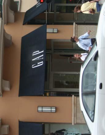
5 Unless otherwise approved by the Planning and Zoning Division as part of a master signage program, the following signs are restricted to fall within the zone identified. 1. Project Identification Signage (Zone A) Primary Multi-Tenant Freestanding Signs (see Photo Exhibit 1.4.2a) Secondary Multi-Tenant Freestanding Signs (see Photo Exhibit 1.4.2b) Individual Parcel Monument Identification Signs (see Photo Exhibit 1.4.2c) Secondary Entry Identification Signs (see Photo Exhibit 1.4.2d) Temporary Project ID Construction Signs (see Photo Exhibit 1.4.2e) Photo Exhibit 1.4.2c Individual Parcel Monument Identification Signs Photo Exhibit 1.4.2a Primary Multi-Tenant Freestanding Signs Photo Exhibit 1.4.2d Secondary Entry Identification Signs Photo Exhibit 1.4.2b Secondary Multi-Tenant Freestanding Signs Photo Exhibit 1.4.2e Temporary Project ID Construction Signs Signage Guidelines 55


 Business Directional Signs (see Photo Exhibit 1.4.")
 Building/Parcel Identification Signs (see Photo Exhibit 1.4.")

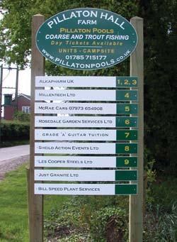
6 2. Internal Directional Signage (Zone B) All signage that is to be located within Zone B is to be submitted with the approved concurrent commercial site development plan as part of the master signage program. Traffic Operational Signs (see Photo Exhibit 1.4.2f) Operational Signage (see Photo Exhibit 1.4.2g) Business Directional Signs (see Photo Exhibit 1.4.2h) Pedestrian Directional Signs (see Photo Exhibit 1.4.2i) Building/Parcel Identification Signs (see Photo Exhibit 1.4.2j) Photo Exhibit 1.4.2h Business Directional Signs Photo Exhibit 1.4.2i Pedestrian Directional Signs Photo Exhibit 1.4.2f Traffic Operational Signage Photo Exhibit 1.4.2g Operational Signage Photo Exhibit 1.4.2j Building/Parcel Identification Signs 56 Signage Guidelines


 Tenant Directory Signs (Photo Exhibit 1.4.2t) Tenant A-Frame Signs (Photo Exhibit 1.")

7 3. Architecture and Pedestrian Zone Signage (Zone C) Primary Tenant Building Marquee Signs (see Photo Exhibit 1.4.2k) Secondary Tenant Building Elevation Signs (see Photo Exhibit 1.4.2l) Wall Mount Signs (see Photo Exhibit 1.4.2m) Projecting Signs (see Photo Exhibit n) Awning and Canopy Signs (see Photo Exhibit 1.4.2o) Hanging Signs (see Photo Exhibit 1.4.2p) Window Signs (see Photo Exhibit 1.4.2q) Plaque Signs (see Photo Exhibit 1.4.2r) Restaurant Menu Signs (Photo Exhibit 1.4.2s) Tenant Directory Signs (Photo Exhibit 1.4.2t) Tenant A-Frame Signs (Photo Exhibit 1.4.2u) Permanent Banner Signs (Photo Exhibit 1.4.2v) Photo Exhibit 1.4.2m Wall Mount Signs Photo Exhibit 1.4.2n Projecting Signs Photo Exhibit 1.4.2k Primary Tenant Building Marquee Sign Photo Exhibit 1.4.2l Secondary Tenant Building Elevation Signs Photo Exhibit 1.4.2o Awning and Canopy Signs Signage Guidelines 57


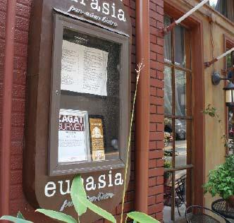
8 Photo Exhibit 1.4.2p Hanging Signs Photo Exhibit 1.4.2s Restaurant Menu Signs Photo Exhibit 1.4.2q Window Signs Photo Exhibit 1.4.2t Tenant Directory Signs Photo Exhibit 1.4.2r Plaque Signs 58 Signage Guidelines


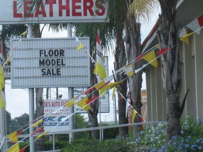
9 instead of providing project identification and direction. Photo Exhibit 1.4.2u Tenant A-Frame Signs Photo Exhibit 1.4.2v Permanent Banner Signs Prohibited Signage The following signs are prohibited and have been defined to be both visually obtrusive and incompatible with the ability to create a safe and aesthetically cohesive streetscape pattern. They are often used to create visual marketing opportunities LCD Signs (see Photo Exhibit 1.4.3a) Motion Light Signs (see Photo Exhibit 1.4.3b) Internal Lit Awning and Canopy Signs (see Photo Exhibit 1.4.3c) Neon Signage (Neon backlit signs may be permitted subject to conditional approval) (see Photo Exhibit 1.4.3d) Single Pole Mount Signs (see Photo Exhibit 1.4.3e) Roof Mounted Signs (see Photo Exhibit 1.4.3f) Billboard Wall Mounted Signs (see Photo Exhibit 1.4.3g) (Exception: or unless otherwise approved by City staff to allow for historical preservation, public art murals, City of Jacksonville neighborhood identifi cation or other public directional or identifi cation usage) (see Photo Exhibit 1.4.5g) Non-Permitted Billboard Signs (see Photo Exhibit 1.4.3h) Billboards located within City public rights-ofways (see Photo Exhibit 1.4.3i) New Private Property Billboards (see Photo Exhibit 1.4.3j) Motion Banners (see Photo Exhibit 1.4.3k) Multiple Flags, Flag Pennant Banners, or other Pennant Strings (see Photo Exhibit 1.4.3l) Inflatable Signs (see Photo Exhibit 1.4.3m) Temporary Product Identification Signs or Banners (see Photo Exhibit 1.4.3n) Temporary or Permanent Interior Window Product Advertisement Signs (see Photo Exhibit 1.4.3o) Temporary Advertisement (Snipe) Signs located within public streetscape zone (see Photo Exhibit 1.4.3p) Secondary Product or Service Advertisement Signage (see Photo Exhibit 1.4.3q) Parking or vehicles that serve to act as temporary or permanent vehicle signage identifying a business or services (see Photo Exhibit 1.4.3r). Signage Guidelines 59


 3b Motion Light Signs 3e")


10 Photo Exhibit 1.4.3a LCD Signs Photo Exhibit 1.4.3d Neon Signage (Note: Neon backlit signs may be permitted and are subject to conditional approval.) Photo Exhibit 1.4.3b Motion Light Signs Photo Exhibit 1.4.3e Single Pole Mount Signs Photo Exhibit 1.4.3c Internal Lit Awning and Canopy Signs 60 Signage Guidelines Photo Exhibit 1.4.3f Roof Mounted Signs


11 Photo Exhibit 1.4.3g Billboard Wall Mounted Signs Photo Exhibit 1.4.3j New Private Property Billboards Photo Exhibit 1.4.3h Non-Permitted Billboard Signs Photo Exhibit 1.4.3k Motion Banners Photo Exhibit 1.4.3i Billboards Located Within City Public Rights-of-Ways Photo Exhibit 1.4.3l Multiple Flags, Flag Pennant Banners or Other Pennant Strings Signage Guidelines 61


12 Photo Exhibit 1.4.3o Temporary or Permanent Interior Window Product Advertisement Signs Photo Exhibit 1.4.3m Inflatable Signs Photo Exhibit 1.4.3p Temporary Advertisement (Snipe) Signs Located Within Public Streetscape Zone Photo Exhibit 1.4.3n Temporary Product Identification Signs or Banners Photo Exhibit 1.4.3q Secondary Product or Service Advertisement Signage 62 Signage Guidelines

13 Photo Exhibit 1.4.3r Temporary or Permanent Vehicle Signage Identifying Business or Services Signage Text Area Standards The following signage text area size guidelines have been developed to create an acceptable standard that allows for ample signage identification area based on roadway frontages while also addressing the pedestrian scale and appropriate scale in relationship to the building architecture. Any variances or deviations from the following guidelines are to be included and visually delineated on the Master Signage Program. Any amendments to these guidelines are subject to review, conditions and approval by the Planning and Zoning Division. 1. Project Identification Signage (Zone A) 1a) Primary Multi-Tenant Freestanding Signs For all multi-tenant projects, one (1) primary multitenant sign shall be permitted for each rights-of-way frontage, as long as each rights-of-way frontage is equal to or exceeds four-hundred (400) linear feet in length. If the rights-of-way frontage is less than four-hundred (400) linear feet, only one (1) primary multi-tenant signs will be permitted. The maximum height of a primary multi-tenant sign shall not exceed fifteen feet (15-0 ) in height and be designed to include the various elements (see Figure 1.4.4(1a)). The maximum text copy area of any multi-tenant sign shall not exceed sixty-five (65) square feet. 1b) Secondary Multi-Tenant Freestanding Signs For all multi-tenant projects that have more than one (1) rights-of-way frontage, one (1) secondary multitenant sign shall be permitted in lieu of a primary multi-tenant freestanding sign, or where a road rightsof-way frontage is less than four-hundred (400) linear feet in length but greater than two-hundred fifty (250) linear feet in length. Only one (1) sign for each rights-of-way frontage is permitted. The maximum height of a secondary multi-tenant sign shall not exceed eight feet (8-0 ) in height, and be designed to include the various elements (see Figure 1.4.4(1b)). The maximum text copy area of any multi-tenant sign shall not exceed forty (40) square feet. 1c) Individual Parcel Monument Identification Signs Individual parcel monument identification signs are limited to only identification of fee simple parcels as approved as part of the master development plan. Only one sign per parcel, located along the primary roadway frontage and centered on the parcel, shall be permitted. If the parcel is a corner parcel, the sign element shall be located at the corner of the intersecting roadways. If the parcel frontage is twohundred (200) linear feet or greater, the maximum height of the sign shall not exceed eight feet (8-0 ) and be designed to include the various elements (see Figure 1.4.4(1ci)). The maximum text copy area of any single sign shall not exceed thirty-six (36) square feet. If the parcel frontage is less than two-hundred (200) linear feet, the maximum height of the sign shall not exceed six feet (6-0 ) and be designed to include the various elements (see Figure 1.4.4(1cii)). The maximum copy area of any single sign shall not exceed sixteen (16) square feet. 1d) Secondary Entry Identification Signs Secondary entry identification signs are limited to one sign per parcel entry, a project or parcel specific logo and the text Entry or Entrance or Exit. They are not permitted to contain any parcel specific names, addresses or other elements mentioned. The maximum size shall not exceed three feet (3-0 ) in height or three feet (3-0 ) in width, and be designed to include the various elements (see Figure 1.4.4(1d)). The maximum text copy area shall not exceed two and one quarter (2.25) square feet. Signage Guidelines 63
 All Signage Copy Area to be Internally Lit Sign")

14 15-0 Maximum Sign Height 12-0 Maximum Sign Area Varies Not to Exceed Maximum Copy Area 65 sq. ft Decorative Signage Cap Required on All Multi-Tenant Signs. Detailing and Fenestration is Subject to Change Based on Individual Sign Design Minimum 9 Surrounding Frame (Scale Proportionate to Signage Face) All Signage Copy Area to be Internally Lit Sign Offset From Base is Required Signage Base Required on All Multi-Tenant Signs. Base Material Shall be Constructed of Durable Materials That Will Not be Damaged by Irrigation Water Maximum Figure 1.4.4(1a) Primary Multi-Tenant Freestanding Sign Note: All Signage Design Must be Characteristic in Style, Architectural Appearance and Color to Architecture of Primary Structure. Cap Height Varies Not to Exceed 2-6 Decorative Signage Cap Required on All Multi-Tenant Signs. Detailing and Fenestration is Subject to Change Based on Individual Sign Design 6 Minimum 6 Surrounding Frame (Scale Proportionate to Signage Face) 8-0 Maximum Sign Height 6-0 Maximum Sign Area Maximum Copy Area 40 sq.ft. 6 6 All Signage Copy Area to be Internally Lit Sign Offset From Base is Required Signage Base Required on All Multi-Tenant Signs. Base Material Shall be Constructed of Durable Materials That Will Not be Damaged by Irrigation Water Figure 1.4.4(1b) Secondary Multi-Tenant Freestanding Sign 8-0 Maximum 64 Signage Guidelines
15 Cap Height Varies Not to Exceed 18 Decorative Signage Cap Required on All Multi-Tenant Signs. Detailing and Fenestration is Subject to Change Based on Individual Sign Design 8-0 Maximum Sign Height 6-0 Maximum Sign Area 2-0 Maximum Copy Area 36 sq.ft. All Signage Copy Area to be Internally Lit Sign Offset From Base is Required Signage Base Required on All Multi-Tenant Signs. Base Material Shall be Constructed of Durable Materials That Will Not be Damaged by Irrigation Water 6-0 Maximum Figure 1.4.4(1ci) Individual Parcel Monument Identification Sign - Parcel Frontage 200 Linear Feet or Greater Cap Height Varies Not to Exceed 12 Decorative Signage Cap Required on All Multi-Tenant Signs. Detailing and Fenestration is Subject to Change Based on Individual Sign Design 6-0 Maximum Sign Height 4-0 Maximum Sign Area 2-0 Maximum Copy Area 16 sq. ft. All Signage Copy Area to be Internally Lit Sign Offset From Base is Required Signage Base Required on All Multi-Tenant Signs. Base Material Shall be Constructed of Durable Materials That Will Not be Damaged by Irrigation Water 4-0 Maximum Figure 1.4.4(1cii) Individual Parcel Monument Identification Sign - Parcel Frontage Less Than 200 Linear Feet Signage Guidelines 65

16 2. Internal Directional Signage (Zone B) All signage that is to be located within Zone B is to be submitted as part of the Master Signage Program and approved concurrent with the commercial site development plan. 2a) Traffic Operational Signs (see Master Signage Program) 2b) Operational Signage (see Master Signage Program) 2c) Business Directional Signs (see Master Signage Program) 2d) Pedestrian Directional Signs (see Master Signage Program) 2e) Building/Parcel Identification Signs (see Master Signage Program) 3. Architecture and Pedestrian Zone Signage (Zone C) All signage that is to be located within Zone C is to be submitted as part of the Master Signage Program and approved concurrent with the commercial site development plan. 3a) Primary Tenant Building Façade Signs (see Figure 1.4.4(3a)) 3b) Secondary Tenant Building Elevation Signs 3c) Wall Mount Signs (see Master Signage Program) 3d) Projecting Signs (see Master Signage Program) 3e) Awning and Canopy Signs (see Figure 1.4.4(3e)) Cap Height Varies Not to Exceed 12 Decorative Signage Cap Required on All Multi-Tenant Signs. Detailing and Fenestration is Subject to Change Based on Individual Sign Design 5-0 Maximum Sign Height 3-0 Maximum Sign Area Maximum Copy Area 2.25 sq.ft. 2 ENTRY 9 All Signage Copy Area to be Internally Lit Sign Offset From Base is Required Signage Base Required on All Multi-Tenant Signs. Base Material Shall be Constructed of Durable Materials That Will Not be Damaged by Irrigation Water 3-0 Maximum Entry or Exit Text Logo Area Not to Exceed 1.5 sq. ft. Figure 1.4.4(1d) Secondary Identification Sign 66 Signage Guidelines
 3k) Tenant Directory Signs (see Master Signage Program) 3l) Tenant A-Frame Signs (see Master Signage Program) 3m) Permanent Banner Signs (see Master Signage")
17 3f) Façade Signs (see Master Signage Program) 3g) Hanging Signs (see Master Signage Program) 3h) Window Signs (see Master Signage Program) 3i) Plaque Signs (see Master Signage Program) 3j) Restaurant Menu Signs (see Master Signage Program) 3k) Tenant Directory Signs (see Master Signage Program) 3l) Tenant A-Frame Signs (see Master Signage Program) 3m) Permanent Banner Signs (see Master Signage Program) Permissible Signage Location Area (Maximum Text Copy Area = 125 SF) Primary Building Entry Facade Building Loggia and Extended Pedestrian Wings are Excluded from Sign Area Calculations and is Not Permitted to Have Signage or Store Logos. Figure 1.4.4(3a) Secondary Identification Sign Signage Guidelines 67


18 1.4.5 Signage Lighting 1.4.5a Signage lighting will depend on the individual signage element, project theming and the lighting requirements for visibility. Since the City of Jacksonville has embraced the Dark Skies site lighting concepts, the lighting for signage elements shall endeavor to support this concept also to the extent possible b Indirect lighting sources shall be strongly encouraged. This form of lighting usually assists in the visual integration of the signage element into the architecture of the building façade (see Photo Exhibit 1.4.5b). Photo Exhibit 1.4.5b Indirect Lighting Source Cast Lighting of Awnings is Permitted Simple logo graphics are permitted on top of awning Awnings Are Not Permitted to be Internally Lit Permissible Text Location for Awning Signs (Maximum Text Copy Height 9 ) Simple Logos or Graphics May be on Top of Awning, but Text is Prohibited Min 1 Space Reveal to be Provided Above and Below Text Figure 1.4.4(3e) Awning Signage 68 Signage Guidelines


: 1.4.")
19 1.4.5c Detached lighting sconces and arm lamps are acceptable, but shall be designed to have vertical cutoff capabilities, either by light fixture shields, baffles or luminaries with internal directional cut-offs. Lighting fixtures shall not obscure the visibility of the signage (see Photo Exhibit 1.4.5c). Photo Exhibit 1.4.5c Detached Lighting Sconce 1.4.5d Internally cabinet lit signs shall be permitted, but limited to the following permitted sign types (see Photo Exhibit 1.4.5d): 1.4.5e The following signs shall be required to be projecting signs but may also be cabinet type: Individual Parcel Monument Identification Signs (Zone A) Secondary Entry Identification Signs (Zone A) Business Directional Signs (Zone B) Building/Parcel Identification Signs (Zone B) Primary Tenant Building Marquee Signs (Zone C) Secondary Tenant Building Elevation Signs (Zone C) These signs shall be required to have non-illuminated, opaque face panels so that only letters and/or logos appear to be backlit. Internally illuminated letters or logos (routed, stenciled/embossed) may be plastic; however, the background of the signage face must be non-reflective in material finish and color (see Photo Exhibit 1.4.5e). Primary Multi-Tenant Freestanding Signs (Zone A) Secondary Multi-Tenant Freestanding Signs (Zone A) Permitted Photo Exhibit 1.4.5d Text Photo Exhibit 1.4.5e Projecting Cabinet Sign Photo Exhibit 1.4.5d Internally Cabinet Lit Sign Signage Guidelines 69

: Primary Multi-Tenant Freestanding Signs (Zone A) Secondary Multi-Tenant Freestanding Signs (Zone A) Individual Parcel Monument Identification Signs (Zone A) Secondary Entry Identification Signs")

20 1.4.5f Indirect uplighting (fluorescent or incandescent) of signs may be used on a limited basis. Care shall be taken to properly shield the light source to prevent glare towards pubic rights-of-ways and onto adjacent properties. Indirect uplighting shall be restricted to the following permitted sign types (see Photo Exhibit 1.4.5f): Primary Multi-Tenant Freestanding Signs (Zone A) Secondary Multi-Tenant Freestanding Signs (Zone A) Individual Parcel Monument Identification Signs (Zone A) Secondary Entry Identification Signs (Zone A) Business Directional Signs (Zone B) Building/Parcel Identification Signs (Zone B) Photo Exhibit 1.4.6a(1) Overly Bright Signage Photo Exhibit 1.4.6a(2) Over-Scaled Signage Photo Exhibit 1.4.5f Indirect Uplighting Signage Materials 1.4.6a Signs shall not include excessively bright colors or have over-scaled letters, graphic symbols or icons deliberately used as a means to attract attention (see Photo Exhibits 1.4.6a(1) and 1.4.6a(2) b Signs shall be professionally constructed and made of permanent durable materials that reflect the architectural theme, colors and finishes, where appropriate. Materials shall not be restricted as to type; however, wood signs shall not be encouraged unless sufficient care is taken to seal the wood to protect it from moisture exposure (see Photo Exhibit 1.4.6b). 70 Signage Guidelines


. Photo Exhibit 1.4.")
21 1.4.6f Temporary Project ID Construction Signs shall be limited to wood or laminate signs and contain graphics of the ultimate proposed site development (see Photo Exhibit 1.4.6f). Photo Exhibit 1.4.6b 1.4.6c Signs shall not be constructed of cloth, paper materials or other materials that will disintegrate due to weather conditions d Exterior materials, finishes and colors shall be similar or complimentary to the building architectural façade on which it is located (see Photo Exhibit 1.4.6d). Photo Exhibit 1.4.6f Temporary Project ID Sign 1.4.6g All electrical raceways and conduits shall be concealed internally to the foundation, wall or bracket holding the signage or signage lighting fixture and be hidden from public view (see Photo Exhibit 1.4.6g). Photo Exhibit 1.4.6d Signage Complementing Architecture 1.4.6e All signage materials, painting and other finishes shall be maintained at all times. Replacement of materials and/or painting shall be the required perpetual maintenance responsibility of the Owner/ Developer. Photo Exhibit 1.4.6g Lighting Source(s) Concealed Signage Guidelines 71
22

23 SECTION 1: COMMERCIAL DEVELOPMENT 1.5 Commercial Landscape and Buffering Design Principles and Guidelines Design Principle The landscape design of a project shall assist in unifying both the overall and individual project into the overall streetscape pattern established. The design shall assist in overall vehicular and pedestrian orientation as well as enhance the pedestrian experience within the project itself. Design Goals To create a landscape design that is sustainable in its form, materials and longevity. To create and reinforce a strong sense of place for each project. To provide for sufficient buffering of surrounding land uses. To complement the architecture by addressing vertical mass, scale and proportion as well as foundation accents, where appropriate. To enhance the pedestrian environment through shade development, visual interest and pedestrian orientation. Photo Exhibit 1.5 Typical R.O.W. Buffer Design Guidelines Although the following design guidelines have been broken down based on specific areas of landscape improvements, it is important to remember that design continuity between the individual areas, as it relates to the whole, is extremely important to achieve a cohesive design theme for the overall project, as well as for adjacent Right of Way ( R.O.W. ) Buffers (see Photo Exhibit 1.5). Commercial Landscape and Buffering 73


24 Urban Streetscape Landscape Buffer Guidelines The following urban streetscape design guidelines have been established to create a minimum standard for urban nodal area design patterning, with respect to the uniform placement of planters, trees and street furniture. These guidelines shall not preclude alternative design solutions that may be incorporated as part of an individually proposed site development and design. Substantial deviation from the proposed minimum guidelines shall be discouraged to maintain consistency in the urban streetscape pattern. For the purposes of clarity, the urban streetscape planting guidelines have been broken down into two different planting zones, as follows (see Figure 1.5): Primary Streetscape Zone Urban Streetscape Nodal Zone Suburban Landscape Buffer Guidelines All R.O.W. buffers shall be designed to provide a distinct visual appearance for the project It shall be strongly suggested that overhead utilities be placed underground during construction to prevent the conflicts between overhead utilities and canopy tree structures. Suburban Development Parcels Urban Nodal Development Parcels Primary Streetscape Zone (Includes rhythmical tree and planter zone patterns with canopy trees located 30-0 o.c., alternative patterns shall be permitted) Urban Streetscape Nodal Zone (includes accent specimen palms or trees, accent paving throughout, upgraded signalization mast arm poles, upgraded lighting to enhance the pedestrian experience, and, where permitted, specialty intersection design) Primary Arterial/ Collector Road Figure 1.5 Streetscape Buffer Zones Adjacent Parcels Primary Arterial/ Collector Road Primary Arterial/ Collector Intersection 74 Commercial Landscape and Buffering
25 1.5.3 If overhead utilities bisect the R.O.W. buffer, a minimum pavement setback of fifteen feet (15-0 ) shall be provided from all utility poles (see Figure 1.5.3) Large canopy trees shall be set back a minimum of twenty feet (20-0 ) from all overhead utility wires (see Figure 1.5.4). Figure Typical R.O.W. Buffer with Bisecting Overhead Utilities Figure Typical R.O.W. Buffer with 20-0 Canopy Tree Setback Commercial Landscape and Buffering 75
26 R.O.W. Perimeter Buffers For all R.O.W. buffers that abut overhead utility easements, a minimum buffer width of twentyfive feet (25-0 ) shall be provided, exclusive of overhead utility easements (see Figure 1.5.5) For all R.O.W. buffers that abut underground utility easements and where there are no overhead utilities, the buffer width shall be a minimum of fifteen feet (15-0 ) in width, exclusive of the utility easement and parking overhangs (see Figure 1.5.6) Where parking abuts the R.O.W. buffer, a solid opaque vegetative screen shall be provided along the entire parking perimeter frontage. A minimum shrub/hedge height at installation shall be three feet (3-0 ) tall. In addition to parking screen shrub/hedge material, a multi-tiered vegetative buffer consisting of trees, shrub material and ground covers shall be provided. Figure Typical R.O.W. Buffer with Parallel Overhead Utilities 76 Commercial Landscape and Buffering Figure Typical R.O.W. Buffer with Parallel Underground Utilities
27 1.5.8 In suburban zones where buildings abut the R.O.W. buffer, the R.O.W. buffer landscape shall be integrated into the building perimeter landscape design (see Figure 1.5.8) R.O.W. buffers shall have a minimum of one (1) canopy tree for every forty (40) linear feet of frontage and a minimum of three (3) understory trees, pines or palms for every eighty (80) linear feet of frontage. At no time shall the total number of pines or palms exceed fifty percent (50%) of the total number of required understory trees. Additionally, fifty percent (50%) of the total number of all understory trees, excluding pines, provided within the R.O.W. buffer must be continuous evergreen species If pines or palms are used within the R.O.W. buffer, they shall be planted in groupings of no less than three (3). If specimen accent palms are proposed, they shall be calculated as one (1) tree and shall be exempt from the cluster requirement R.O.W. buffer canopy tree sizes shall be a minimum of fourteen feet (14-0 ) in height, with a minimum of a four-inch (4 ) caliper as defined by the Florida Grades and Standards for Nursery Stock. R.O.W. buffer understory trees shall be a minimum of eight feet (8-0 ) in height, with a minimum caliper of two inches (0-2 ). All multitrunk understory trees shall have a minimum of three (3) primary trunks, with a minimum caliper of two inches (0-2 ) per trunk at installation. All pine and palm groupings shall be installed in staggered heights with the minimum palm tree clear trunk height of no less than eight feet (8-0 ) and a minimum pine height of eight feet (8-0 ). Figure Typical R.O.W. Buffer with Building Pulled Forward to Street Commercial Landscape and Buffering 77
28 Internal Perimeter Buffers Abutting Commercial/ Industrial Uses For all internal perimeter buffers that abut overhead utility easements, a minimum buffer width of ten feet (10-0 ) shall be provided, exclusive of overhead utility easements (see Figure ) For all internal perimeter buffers that abut underground utility easements, the landscape buffer shall be a minimum of seven feet (7-0 ) in width, exclusive of the utility easement and parking overhangs (see Figure ). Figure Typical Commercial and Industrial Perimeter Buffer with Parallel Overhead Utilities 7-0 Figure Typical Commercial and Industrial Perimeter Buffer with Parallel Underground Utilities 78 Commercial Landscape and Buffering
29 Where parking abuts the internal perimeter buffer, a solid opaque vegetative screen shall be provided along the entire parking perimeter frontage. A minimum shrub/hedge height at installation shall be a minimum of thirty inches (0-30 ) at the time of installation and maintained at thirty-six (0-36 ) at maturity (see Figure ) Internal perimeter buffers shall have a minimum of one (1) canopy tree for every fifty (50) linear feet of frontage and a minimum of three (3) understory trees, pines or palms for every one-hundred (100) linear feet of frontage. At no time shall the total number of pines or palms exceed fifty percent (50%) of the total number of required understory trees. Additionally, fifty percent (50%) of the total number of all understory trees, excluding pines, provided within the internal perimeter buffer shall be continuous evergreen species If pines or palms are used with the internal perimeter buffer, they shall be planted in groupings of no less than three (3). If specimen accent palms are used each palm will count as one (1) tree Internal perimeter buffer canopy tree sizes shall be a minimum of twelve feet (12-0 ) in height, with a minimum three-inch (3 ) caliper. Internal buffer understory trees shall be a minimum of ten feet (10-0 ) in height, with a minimum caliper of two inches (0-2 ). All multi-trunk understory trees shall have a minimum of three (3) primary trunks, with a minimum caliper of one and one-quarter inches (0-1 1/4 ) per trunk at installation. All pine and palm groupings shall be installed in staggered heights with the minimum palm tree clear trunk height of no less than eight feet (8-0 ), and a minimum pine height of eight feet (8-0 ). Figure A visual landscape screen shall be a minimum of 30 from the time of installation. Commercial Landscape and Buffering 79
30 Perimeter Buffers Abutting Residential Uses For all residential perimeter buffers that abut overhead utility easements, a minimum buffer width of twenty-five feet (25-0 ) shall be provided, exclusive of overhead utility easements and parking overhangs (see Figure ) For all residential perimeter buffers that abut underground utility easements, and where there are no overhead utilities, the minimum buffer width shall be a minimum of twenty feet (20-0 ) in width, exclusive of the utility easements and parking overhang (see Figure ). Figure Typical Residential R.O.W. Buffer with Parallel Overhead Utilities Figure Typical Residential R.O.W. Buffer with Parallel Underground Utilities 80 Commercial Landscape and Buffering
31 Where parking abuts the residential perimeter buffer, a solid opaque vegetative screen shall be provided along the entire parking perimeter frontage. An eight-foot (8-0 ) solid masonry wall, a combined eight-foot (8-0 ) berm and vegetative buffer combination or combination of the two shall be provided (see Figure a). If a vegetative buffer shall be installed, a fourfoot (4-0 ) berm (maximum 4:1 slope each side) and a minimum of a four-foot (4-0 ) solid vegetative buffer shrub/hedge shall be provided at installation. The vegetative buffer must be able to attain a height of six feet (6-0 ) within one year of installation (see Figure b). Figure a Typical Residential Perimeter Buffer with 8-0 Masonry Walls Figure b Typical Residential Perimeter Buffer with Buffer Hedge. Commercial Landscape and Buffering 81
 linear feet of frontage. At no time shall the total number of pines or palms exceed fifty percent (50%) of the total number of required understory trees.")
32 Residential perimeter buffers shall have a minimum of one (1) canopy tree for every forty (40) linear feet of frontage and a minimum of three (3) understory trees, pines or palms for every forty (40) linear feet of frontage. At no time shall the total number of pines or palms exceed fifty percent (50%) of the total number of required understory trees. Additionally, fifty percent (50%) of the total number of all understory trees, excluding pines, provided within the R.O.W. buffer must be continuous evergreen species If pines or palms are used with the residential perimeter buffer, they shall be planted in groupings of no less than three (3) (see Photo Exhibit ) Internal perimeter buffer canopy tree sizes shall be a minimum of twelve feet (12-0 ) in height, with a minimum three-inch (0-3 ) caliper. Internal buffer understory trees shall be a minimum of eight feet (8-0 ) in height, with a minimum caliper of two inches (0-2 ). All multi-trunk understory trees shall have a minimum of three (3) primary trunks, with a minimum caliper of one and onequarter inch (0-1 1/4 ) per trunk at installation. All pines and palms groupings shall be installed in staggered heights with the minimum palm tree clear trunk height of no less than eight feet (8-0 ) and a minimum pine height of eight feet (8-0 ). Primary Entry Drive Landscape Guidelines All primary access drives entering a project site from a public R.O.W. shall provide a minimum of ten feet (10-0 ) of landscape buffer between the drive and the adjacent parking or buildings. All landscape buffer widths are exclusive of any car overhangs (see Figure ). Photo Exhibit Palms shall be grouped together in perimeter buffers 82 Commercial Landscape and Buffering
 maintained with pedestrian access provided along entry drive Drive width as determined by the number of lanes and required fire safety access standards Figure 1.5.")
33 10-0 min. Landscape Buffer required between edge of drive and entry abutting parking (dimension taken from the back of curb) Landscape Buffer (15-0 min.) maintained with pedestrian access provided along entry drive Drive width as determined by the number of lanes and required fire safety access standards Figure Primary Commercial Entry Landscape 5-0 min. sidewalk 12-0 Entry divider median required at all primary project entrances (dimension from back of curb) Landscape within the ten-foot (10-0 ) entry buffer strips shall be designed to accentuate the entry drive sequence and assist in providing orientation and direction to the vehicular driver Shrub landscape material within the ten-foot (10-0 ) entry buffer strips shall provide opaque visual buffering of the adjacent parking areas. Shrub material shall be a minimum of thirty-six inches (0-36 ) in height at the time of installation and shall be able to attain a minimum height of forty-eight inches (0-48 ) within one year. A combination of canopy trees, palms, understory trees, shrubs and groundcovers shall be installed to provide visual interest to the entry drive approach Where pedestrian access is provided along the primary entry access drive, a minimum landscape buffer width of fifteen feet (15-0 ) shall be provided to allow for a walkway to be inset into the landscape planting areas and to prevent the walkway from abutting the actual drive or interior parking area itself. All landscape buffer widths are exclusive of any proposed car overhangs (i.e., 2-0 overhang + a 15-0 buffer = 17-0 minimum landscape buffer width) (see Figure ). Parking Area Landscape Guidelines All parking aisles shall be terminated by a terminal landscape island. Commercial Landscape and Buffering 83
 dimension shall be measured from the midpoint of the adjacent parking space.")
34 All terminal islands shall be a minimum of fifteen feet (15-0 ) in width, as measured from the back of curb. If a radial terminal island is proposed, the fifteen-foot (15-0 ) dimension shall be measured from the midpoint of the adjacent parking space. No car overhangs shall be permitted over terminal islands All interior parking islands shall be a minimum width of ten feet (10-0 ) (see Figure ) Interior parking islands shall be provided every ten (10) spaces. In the event that a run extends to up to twelve (12) spaces, relief will be provided to allow for the island to fall at the end of the twelfth space. Note: Every effort must be made to design the parking area to accommodate interior and terminal parking islands on ten (10) space centers All parking spaces abutting terminal or interior parking islands shall be ten feet (10-0 ) in width to allow for door swing and pedestrian step out without encroaching in the landscape island (see Figure ) Interior diamond planter islands are not acceptable and shall not to be used (see Figure ) Interior parking median dividers shall be located between every third aisle of parking. All divider medians shall be a minimum width of ten feet (10-0 ), as measured from the back of curb. All landscape buffer widths are exclusive of any car overhangs proposed (i.e. 2-0 overhang provided minimum landscape buffer width) (see Figure ) measured to inside of curb 10-0 measured to outside of curb 9-6 or typical width as approved Wider parking space allows for passenger and driver to exit vehicle without stepping out into planter bed. Figure The minimum width of parking spaces located adjacent to planters shall be Commercial Landscape and Buffering

 Concrete Wheel Stops Provided 6 Curb Used as Wheel Stop 2-0 Car Overhang Into Divider Median 14-0 10-0 Figure 1.5.")
35 Parking Diamond Planters are not Permitted Due to Car Overhang Encroachment And Insufficient Growing Medium and Surface Area Needed to Promote Consistency and Healthy Trees. Figure Interior diamond planters shall not be permitted Wide Divider Measured from Back of Curb. Required Due to 2-0 Overhang Encroachment of Cars into Planter 2-0 Car Overhang Does Not Encroach Into Planter Divider Island 10-0 Wide Divider Median Measured From Back of Curb Permitted (No Car Overhangs Protrude into Planter) Concrete Wheel Stops Provided 6 Curb Used as Wheel Stop 2-0 Car Overhang Into Divider Median Figure Interior parking islands shall account for bumper overhang. Commercial Landscape and Buffering 85
 (see Photo Exhibit 1.")
36 Where pedestrian access is provided within the parking divider medians, a minimum landscape buffer width of twenty feet (20-0 ) shall be provided to allow for a walkway to be inset into the landscape planting areas and to prevent the walkway from abutting the actual drive or interior parking area itself. All landscape buffer widths are exclusive of any car overhangs proposed (i.e minimum landscape buffer width overhang provided = 22-0 minimum landscape buffer width) (see Photo Exhibit ) Each interior planter island shall be planted with a minimum of one (1) canopy shade tree (per parking row) measuring twelve feet high with a six foot spread (12-0 ht. x 6-0 spr.) as selected from the approved plant list (see Appendix B) Each terminal planter island shall be planted with a minimum of one (1) canopy shade tree (per parking row) measuring twelve feet high with a six-foot spread (12-0 ht. x 6-0 spr.), one (1) understory tree (per parking row) or a cluster of palms (per parking row) measuring ten feet high with a five-foot spread (10-0 ht. x 5-0 spr.), as selected from the approved plant list (see Appendix B). The use of specimen palms in landscape islands is excluded from the 3:1 cluster requirement The maximum height of any shrub material in all terminal planter islands shall not exceed thirty-six inches (0-36 ) at maturity All plant materials within twenty-four inches (0-24 ) of the edge of terminal or interior parking islands is not to exceed twenty-four inches (0-24 ) in height. Permitted Photo Exhibit A minimum twenty-foot (20-0 ) wide landscape buffer shall be provided to allow for a pedestrian walkway All terminal and interior planter islands shall be landscaped with plant material selected from the approved plant list. A minimum coverage of fifty percent (50%) shall be provided throughout each island All planting islands, terminal islands, building planters, etc. are to be over excavated to a depth of three feet (3-0 ) to remove all site fill soils, rock and deleterious materials and organics and all pavement subbase materials. All islands and planters are to be backfilled with soil material that provides positive drainage and promotes vigorous growth of installed plant materials (see Figure ). 86 Commercial Landscape and Buffering

37 Finished Pavement Grade Top of Curb Tree/Palm Rootball Tree or Rootball to be Set at or Slightly Above Grade. Contractor to Adjust for Potential Settlement of Backfill Soil to Prevent Excessive Tree/Palm Settlement Finish Grade to be Crowned 9 Above Top of Curb 3-0 Min. Finish Grade to be 3 Below Top of Curb Landscape Contractor to Backfill All Islands with Soil Material that Allows for Positive Drainage and Promotes Vigorous Growth of Installed Plant Materials. Figure All planters shall be excavated to a minimum depth of (3-0 ). Site Work Contractor to Over Excavate all Subbase and Planting Areas to a Depth of no Less than 3-0 Commercial Landscape and Buffering 87
 below top of curb to allow for installation of mandatory two inch (0-2 ) mulch bed depth (see Figure 1.5.42). + 9 10-0 Min.")
38 All parking islands and terminal end islands shall be backfilled and crowned to a height of nine inches (0-9 ) above top of curb. Finish soil grade after planting shall be three inches (0-3 ) below top of curb to allow for installation of mandatory two inch (0-2 ) mulch bed depth (see Figure ) Min. to Inside Edge of Curb 2 Radius Radius Perimeter Curb Around Parking Island Figure All parking islands shall be back filled and crowned. 88 Commercial Landscape and Buffering
 grade, PVC weep holes shall be installed at the low end of each island to prevent excessive buildup of irrigation water in island")
39 All parking islands and terminal islands shall be saw cut at a minimum of five feet (5-0 ) on center to a depth of the finished pavement surface to allow for drainage of islands. If the longitudinal slope of the island exceeds a four percent (4%) grade, PVC weep holes shall be installed at the low end of each island to prevent excessive buildup of irrigation water in island (see Figure ). 1/2 PVC Weep Hole Placed at 5-0 O.C. at End of Island Typical 6 Curb Finished Pavement Grade Top of Curb Pavement Subbase Slope of Planter Island at 4% or Greater Top of Curb Longitudinal Slope of Pavement 4% or Greater Figure All parking islands shall be saw cut at a minimum of 5-0. Backfilled Soil Material Commercial Landscape and Buffering 89
 in width, the offset distance of the shrub shall be increased to allow for full growth to prevent")
 Finished Pavement Grade 2-0 to Center of Plant Tree/Palm Rootball Maximum Depth of")
40 All shrub material in planting islands is to be set back a minimum of two feet (2-0 ) from back of curb to allow for ultimate growth of shrub materials. If the ultimate growth of the proposed plant material will exceed twenty-four inches (0-24 ) in width, the offset distance of the shrub shall be increased to allow for full growth to prevent excessive pruning. Ground covers that are designed to attain onehundred percent (100%) coverage of island or form a solid mass to back of curb is excluded (see Figures a and b). 3 Mulch Depth Finish Grade of Soil to be 3 BelowTop of Curb Poured in Place Curb (No Extruded Curb Permitted) Finished Pavement Grade 2-0 to Center of Plant Tree/Palm Rootball Maximum Depth of Subbase Behind Back of Curb Not to Exceed 12 Unless it is Determined That Due to Sub-Surface Soil Conditions it Must Exceed. At no Point Shall the Subbase Extend More Than 18 Behind Back of Curb Figure a All planting island material shall be set back 2-0 from the back of curb. Shrubs to be Planted at Least 2-0 Behind Back of Curb to Prevent Damage From Vehicle Door Figure b Shrubs shall be planted 2-0 from the back of curb. 90 Commercial Landscape and Buffering

41 Building Façade Zone Landscape Guidelines The Building Façade Zone is located adjacent to any building, on all sides. The zone includes the Pedestrian Zone within the recommended setback. Special considerations for development in the areas can greatly increase the perceived quality of a commercial development due to its high visibility position All plants in the Building Façade Zone shall compliment and reinforce the character of the building while highlighting entrance features (see Photo Exhibit ) Landscaping shall be considered an integral buffer to the overall design of the Building Façade Zone Foundational landscape in planters within the Building Façade Zone shall be comprised of shrubs, groundcovers and trees. Shrubs shall be limited to three feet (3-0 ) in height. Trees shall be ornamental or shade trees. Tree branches shall be maintained to provide for a desired ten-foot (10-0 ) clearance above the ground plane. Foundational plantings shall consist of evergreen shrubs and groundcovers. Large expanses of mulch are not desired Accent plantings within the Building Façade Zone shall be used to create a rhythm and aesthetic pattern of planting Irrigation systems shall be designed by a licensed landscape architect or others certified by the State of Florida to provide irrigation design services. Design and building contractors or others that do not posses a similar certification shall not be permitted to design irrigation systems Irrigation systems shall be installed in all Building Façade Zone planters. Permitted Photo Exhibit Landscape placement and sizes have been designed to accent architectural façades and highlight entrance locations The Building Façade Zone planters shall not interfere with the façade or pedestrian circulation Vegetation in the Building Façade Zone shall be designed so as to not block views through windows Seat walls, benches, perches, pedestrian scale lighting and waste receptacles shall be incorporated in the Building Façade Zone and the overall site plan The Building Façade Zone shall, when possible, connect open space and amenities, including play areas, plazas, public parks, green spaces, water features and focal points Large planter pots can substitute for planters in approved instances. Commercial Landscape and Buffering 91

. Permitted Photo Exhibit 1.5.56 Grouped trees shall be planted surrounding retention ponds. Permitted Building façade pedestrian environment has been well designed.")
42 Wetland and upland trees shall be planted around the perimeters of any proposed wet or dry stormwater pond, at a ratio of three (3) trees per seventy-five (75) linear feet, or fraction thereof. Trees are to be grouped to create a natural massing appearance. A mixture of wetland tree species shall be used to create both visual and ecological diversity (see Photo Exhibit ). Permitted Photo Exhibit Grouped trees shall be planted surrounding retention ponds. Permitted Building façade pedestrian environment has been well designed. Layering of multiple sizes and masses of plantings create a good sense of human scale. 92 Commercial Landscape and Buffering


43 Permitted Not Permitted Permitted Pedestrian scale is reinforced through the use of small scale plantings that accent and compliment the architecture. Not Permitted This planting design lacks any sense of pedestrian scale and has been designed to only provide vertical scale to the building façade. Permitted The pedestrian and vehicular streetscape environment has been addressed within this design. Sufficient tree offsets from both drive lanes and the sidewalk has been provided. Not Permitted The building façade lacks any landscape foundation planting to visually soften transition of building to parking lot. Commercial Landscape and Buffering 93


44 Permitted Not Permitted Permitted Interior perimeter buffer with adequate buffer width, landscape shrub material and tree spacing to buffer adjacent commercial activities from neighboring commercial development. Not Permitted Building façade is not addressed by landscape design. No vertical elements are provided to accent vertical façades or break up long façade expanses. Not Permitted Permitted Car overhang strip used to protect plant material from vehicle damage. Lack of buffering creates continuous concrete plane at commercial centers along roadways. 94 Commercial Landscape and Buffering


45 Permitted Not Permitted Permitted Building façade plantings create inviting pedestrian experience and accentuate architecture. Not Permitted Building façade lacks any foundational planting at primary entrance to building. Permitted Various layering of trees and shrubs against the building façade help to provide human scale to the architecture. Not Permitted Lack of any building foundational planting makes this building appear imposing and harsh. Commercial Landscape and Buffering 95


46 JACKSONVILLE DESIGN GUIDELINES AND Permitted Not Permitted Permitted Not Permitted Planting designs that incorporate a multitude and variety of plants encourage buffering goals. Plantings, as shown, represent what is currently permitted as code minimum by most cities. This design lacks any public streetscape appeal and portrays an image for the project as being low scale. Permitted Not Permitted Planting designs along R.O.W. that buffer commercial projects shall have continuous groundcover. The pedestrian environment and building frontage seen here lack any buffer landscape plantings. 96 Commercial Landscape and Buffering
D. Landscape Design. 1. Coverage Intent: To provide adequate landscaping materials that enhance the appearance of development projects.
 D. Landscape Design The standards and guidelines in this section give design guidance for the landscaping components of industrial and office projects. City regulations require that all landscaping be
DEVELOPMENT CONTROLS MEDICAL DISTRICT
 6.01. GENERAL DESIGN GUIDELINES A. Site Planning B. Architectural Design C. Medical Facility Signage & Lighting D. Exhibit 48. ARCHITECTURAL DESIGN CONCEPTS 6.02. MEDICAL FACILITY STANDARDS & GUIDELINES
CHAPTER 3. Design Standards for Business, Commercial, Industrial, Recreational and Institutional Uses
 CHAPTER 3 Design Standards for Business, Commercial, Section Number Title Ordinance Number Date of Ordinance 16-3-1 Applicability 2006-11 2008-04 07-01-08 16-3-2 Uniform Standards for Architectural Design
FREEWAY/TOURIST DISTRICT
 FREEWAY/TOURIST DISTRICT DESIGN STANDARDS FOR THE CITY OF MOUNTLAKE TERRACE March, 2014 MOUNTLAKE TERRACE FREEWAY/TOURIST DESIGN STANDARDS March, 2014 1 TABLE OF CONTENTS Introduction...1 Design Site Design
CHAPTER ADDITIONAL REQUIREMENTS IN THE NC, NEIGHBORHOOD COMMERCIAL ZONE
 CITY OF MOSES LAKE MUNICIPAL CODE CHAPTER 18.31 ADDITIONAL REQUIREMENTS IN THE NC, NEIGHBORHOOD COMMERCIAL ZONE Sections: 18.31.010 Purpose 18.31.020 Minimum Lot Area 18.31.030 Setbacks 18.31.040 Maximum
BUFFERS, TREE PROTECTION AND LANDSCAPING. Sec Purpose and Intent.
 ARTICLE 20 BUFFERS, TREE PROTECTION AND LANDSCAPING Sec. 20.1. Purpose and Intent. Trees improve air and water quality, reduce soil erosion, reduce noise and glare, provide habitat for desirable wildlife,
ARTICLE 5 LANDSCAPE IMPROVEMENTS
 ARTICLE 5 LANDSCAPE IMPROVEMENTS 5-1 Purpose and Applicability 5-2 Landscape Plans and Installation 5-3 Landscaping Standards 5-4 Landscape Maintenance ARTICLE 5-1 PURPOSE AND APPLICABILITY 5-1-1 Purpose
The purpose of the requirements in this Article is to provide for landscaping and screening of parking and other outdoor areas that will:
 XIII. LANDSCAPING & SCREENING A. Purpose The purpose of the requirements in this Article is to provide for landscaping and screening of parking and other outdoor areas that will: 1. Protect residential
VILLAGE OF SKOKIE Design Guidelines for Mixed-Use Districts NX Neighborhood Mixed-Use TX Transit Mixed-Use CX Core Mixed-Use
 VILLAGE OF SKOKIE Design Guidelines for Mixed-Use Districts NX Neighborhood Mixed-Use TX Transit Mixed-Use CX Core Mixed-Use TABLE OF CONTENTS CHAPTER 1 SITE DESIGN Purpose 1 CHAPTER 2 SITE DESIGN Streetscape
AIRPORT BUSINESS PARK
 PIER MAC PETROLEUM INSTALLATION LTD. AIRPORT BUSINESS PARK DEVELOPMENT APPLICATIONS March 2003 4.1 Airport Business Park Development Permit Area 4.1.1 Justification/Design Concept The design concept envisioned
Chapter 11. Industrial Design Guidelines 11.1 INTRODUCTION AND PURPOSE 11.3 SITE PLANNING GUIDELINES 11.2 GENERAL DESIGN OBJECTIVES
 Chapter 11 Industrial Design Guidelines 11.1 INTRODUCTION AND PURPOSE The following industrial/design guidelines seek to assure high quality development in Santa Ana s industrial districts by: The design
ARTICLE XII BUFFER REQUIREMENTS
 ARTICLE XII 1200. Intent. It is the intent of this section to establish standards to provide for buffer amenities and screening throughout unincorporated Georgetown County. The purpose of these standards
TOWN CENTER DESIGN STANDARDS FOR THE CITY OF. August, MOUNTLAKE TERRACE TOWN CENTER DESIGN STANDARDS August,
 TOWN CENTER DESIGN STANDARDS FOR THE CITY OF MOUNTLAKE TERRACE August, 2008 MOUNTLAKE TERRACE TOWN CENTER DESIGN STANDARDS August, 2008 1 TABLE OF CONTENTS Introduction...3 Design Site Design...4 Pedestrian
ARTICLE 9: Landscaping
 ARTICLE 9: Landscaping 9-10 Legislative Intent The purpose of this Article is to regulate the planting and preservation of landscape materials; to facilitate the creation of an attractive and healthy environment;
City of Aurora Planning Department DESIGN STANDARDS FOR MOTOR VEHICLE FUEL DISPENSING STATION. August 3, 1998
 City of Aurora Planning Department DESIGN STANDARDS FOR MOTOR VEHICLE FUEL DISPENSING STATION August 3, 1998 1. GENERAL PURPOSE AND APPLICABILITY The following design standards for motor vehicle fuel dispensing
CHAPTER 8 LANDSCAPE REGULATIONS
 CHAPTER 8 LANDSCAPE REGULATIONS Section 8.01 Intent. Landscaping is an essential element of the site design process, and is an important feature in promoting the public health, safety, comfort, general
lot flankage Y street 16m 6m landscape strip for large site 3m landscape strip for small medium site
 Commercial General Commercial Objectives Create developments compatible with adjacent land uses in scale, function and character Define a consistent and attractive street edge with quality landscaping,
Landscaping Standards
 CHAPTER 29 ARTICLE 403 29.403 Landscaping Standards Purpose: The purpose of this section is to protect and promote the public health, safety and general welfare by requiring landscaping in relation to
5.1.1 The streetscape along US Highway 64 (Brevard Road); and, The built environment within new residential developments; and,
; and, The built environment within new residential developments; and,") Article 5. Landscaping 5.1 Purpose The Town of Laurel Park s landscape standards are designed to create a beautiful, aesthetically pleasing built environment that will complement and enhance community
Article 5. Landscaping 5.1 Purpose The Town of Laurel Park s landscape standards are designed to create a beautiful, aesthetically pleasing built environment that will complement and enhance community
Community Design Plan
 Gardena General Plan 2006 Authority While the is not a required element of a General Plan, it is included because improving the community appearance and image is paramount to the overall quality of life
Chapter PEDESTRIAN COMMERCIAL (PC) ZONING DISTRICT
 ZONING DISTRICT") Chapter 11-17 PEDESTRIAN COMMERCIAL (PC) ZONING DISTRICT Sections: 11-17-01 GENERAL PURPOSE 11-17-02 PERMITTED BUILDING TYPES 11-17-03 USES PERMITTED WITH DESIGN REVIEW 11-17-04 USES PERMITTED BY CONDITIONAL
Chapter 11-17 PEDESTRIAN COMMERCIAL (PC) ZONING DISTRICT Sections: 11-17-01 GENERAL PURPOSE 11-17-02 PERMITTED BUILDING TYPES 11-17-03 USES PERMITTED WITH DESIGN REVIEW 11-17-04 USES PERMITTED BY CONDITIONAL
Chapter 19.5 LANDSCAPING REQUIREMENTS
 Chapter 19.5 LANDSCAPING REQUIREMENTS Sec. 19.5-1. Intent The intent of the landscaping requirements stated herein are as follows: To aid in stabilizing the environment's ecological balance by contribution
180 ZONING 180. ARTICLE XLII STREETSCAPE ENHANCEMENT OVERLAY ( SEO ) DISTRICT [Added Ord. No. 1086]
![180 ZONING 180. ARTICLE XLII STREETSCAPE ENHANCEMENT OVERLAY ( SEO ) DISTRICT [Added Ord. No. 1086]](/thumbs/75/72360049.jpg "180 ZONING 180. ARTICLE XLII STREETSCAPE ENHANCEMENT OVERLAY ( SEO ) DISTRICT [Added Ord. No. 1086]") 180 ZONING 180 ARTICLE XLII STREETSCAPE ENHANCEMENT OVERLAY ( SEO ) DISTRICT [Added 4-6-2016 Ord. No. 1086] 180.145. SEO DISTRICT 180.145.1. Intent. The SEO DISTRICT Regulations are intended to address
180 ZONING 180 ARTICLE XLII STREETSCAPE ENHANCEMENT OVERLAY ( SEO ) DISTRICT [Added 4-6-2016 Ord. No. 1086] 180.145. SEO DISTRICT 180.145.1. Intent. The SEO DISTRICT Regulations are intended to address
ELK GROVE TOWN CENTER DESIGN GUIDELINES
 ......... ELK GROVE TOWN CENTER DESIGN GUIDELINES LAGUNA RIDGE SPECIFIC PLAN... June 2008 ............ DESIGN GUIDELINES Table of Contents Contents Section A: Town Center Overview...1 A.1. Purpose and
SUBCHAPTER 4-B GUIDELINES FOR THE B-3 COMMERCIAL CHARACTER AREA
 1 SUBCHAPTER 4-B GUIDELINES FOR THE B-3 COMMERCIAL CHARACTER AREA Downtown Bozeman should be the location of buildings of greatest height and intensity in the community. The following guidelines apply
ARTICLE XIX SCREENING, LANDSCAPING AND TREES
 ARTICLE XIX SCREENING, LANDSCAPING AND TREES Part I. Landscaping and Screening Section 304 Purpose. The purpose of this Part is to establish minimum landscaping and screening requirements that provide
F. Driveways. Driveways which provide access to off-street parking or loading from public streets shall comply with the following:
 Section 20.945.040 General Design Standards for Surface Parking Areas. A. Review Authority. Parking lot design and drainage shall be subject to review and approval of the City Transportation Manager. B.
Landscape and fencing requirements of this Chapter shall apply to all new landscaped areas.
 Chapter 19.06. Landscaping and Fencing. Sections: 19.06.01. Purpose. 19.06.02. Required Landscaping Improvements. 19.06.03. General Provisions. 19.06.04. Landscaping Plan. 19.06.05. Completion of Landscape
4.0 business park design guidelines
 city of antioch citywide design guidelines manual 4.0 business park design guidelines 4.1 introduction The intent of the business park design guidelines is to aid private development in the creation of
13. New Construction. Context & Character
 13. New Construction Context & Character While historic districts convey a sense of time and place which is retained through the preservation of historic buildings and relationships, these areas continue
general corridor design guidelines gen-0.0
 general corridor design guidelines gen-0.0 facades gen-1.0 GEN-1.1: TRANSPARENCY GEN-1.1.1: WALL OPENINGS In order to create buildings that are visually interesting for passers-by, blank ground floor
SECTION RESIDENTIAL LANDSCAPING, STREETSCAPING, AND AMENITY STANDARDS
 SECTION 3.5400 RESIDENTIAL LANDSCAPING, STREETSCAPING, AND AMENITY STANDARDS 3.5401 RESIDENTIAL LANDSCAPE STANDARDS a) These standards shall apply to any single family detached and duplex residential zoning
CENTERS AND CORRIDORS
 INITIAL DESIGN STANDARDS AND GUIDELINES for CENTERS AND CORRIDORS City of Spokane Planning Services Third Floor, City Hall 808 W. Spokane Falls Blvd. Spokane, WA 99201-3329 (509) 625-6300 www.spokaneplanning.org
ARTICLE II. LANDSCAPING
 ARTICLE II. LANDSCAPING Sec. 35-31. Landscaping required for all site development. (a) Residential Developments: (1) All residential lots shall provide a minimum of one (1) boulevard tree (planted between
VEHICULAR AND PEDESTRIAN CIRCULATION
 This perspective sketch communicates the intended character and quality of a proposed streetscape design. Locate benches near a major intersection where people tend to gather. Seating and lighting provide
4. INDUSTRIAL 53 CASTLE ROCK DESIGN
 4. INDUSTRIAL 53 CASTLE ROCK DESIGN CASTLE ROCK DESIGN 54 4. INDUSTRIAL Overview Well-designed and attractive industrial centers are the product of blending economic realities with both functional and
5.7 Design Criteria for the Private Realm Organization of Private Realm Design Standards and Guidelines Guidelines vs.
 5.7 Design Criteria for the Private Realm The Private Realm (shown in Exhibit 5.7a) includes the privately owned property not included in the Setback Realm described in the previous section. It encompasses
U.S. Highway 377 North Overlay District. 1. General Purpose and Description
 U.S. Highway 377 North Overlay District 1. General Purpose and Description The purpose of the U.S. Highway 377 North Overlay District is to implement the recommendations within the U.S. Highway 377 North
GENERAL LANDSCAPE PROVISIONS. The following landscape provisions shall be adhered to by all land uses unless otherwise noted:
 CHAPTER 1.18 Sections: 1.18.005 Purpose. 1.18.010 Landscaping, Buffering, and Fencing Improvements Required. 1.18.015 General Landscape Provisions. 1.18.020 Landscaping Plan. 1.18.025 Single-Family Dwellings
Future Five. Design/ Development Guidelines. January 2008 Amended June 08 per City Council motion
 Future Five Design/ Development Guidelines January 2008 Amended June 08 per City Council motion 5-Points Design Guidelines Table of Contents I. Introduction 3 II. Area boundaries 4 III. Review Process
VILLAGE OF CHANNAHON COMMERCIAL DESIGN GUIDELINES. Village of Channahon S. Navajo Drive Channahon, IL (815)
") VILLAGE OF CHANNAHON COMMERCIAL DESIGN GUIDELINES Village of Channahon 24555 S. Navajo Drive Channahon, IL 60410 (815) 467-6644 www.channahon.org Adopted March 6, 2006 VILLAGE OF CHANNAHON COMMERCIAL DESIGN
VILLAGE OF CHANNAHON COMMERCIAL DESIGN GUIDELINES Village of Channahon 24555 S. Navajo Drive Channahon, IL 60410 (815) 467-6644 www.channahon.org Adopted March 6, 2006 VILLAGE OF CHANNAHON COMMERCIAL DESIGN
5.1 Commercial and Industrial Development. (Effective April 1, 2006)
") 5.1 Commercial and Industrial Development. (Effective April 1, 2006) A. Applicability: The requirements of this section (5.10) shall apply to all uses within the LB Local Business; HB Highway Business;
5.1 Commercial and Industrial Development. (Effective April 1, 2006) A. Applicability: The requirements of this section (5.10) shall apply to all uses within the LB Local Business; HB Highway Business;
3.13. Development Guidelines
 3.3 Landscaping Elements Landscaping should be used to frame and soften structures, define site functions, enhance the quality of the environment, and screen undesirable views. Safety, environmental impacts,
Article 10: Landscaping and Buffering
 10.01: Purpose Article 10: Landscaping 10.01: Purpose The purpose of this article is to: A) Promote and protect the interest of the public convenience, comfort, prosperity, or general welfare in accordance
LANDSCAPE ORDINANCE PASADENA PLANNING DEPARTMENT (713) FAX (713)
 FAX (713)") LANDSCAPE ORDINANCE PASADENA PLANNING DEPARTMENT (713) 475-5543 FAX (713) 477-1072 ARTICLE X. LANDSCAPING OF NONRESIDENTIAL SITES* Sec. 9-195. Applicability. (a) This article shall apply to the following:
LANDSCAPE ORDINANCE PASADENA PLANNING DEPARTMENT (713) 475-5543 FAX (713) 477-1072 ARTICLE X. LANDSCAPING OF NONRESIDENTIAL SITES* Sec. 9-195. Applicability. (a) This article shall apply to the following:
The Highway Overlay District applies to an area within the City of Papillion's zoning jurisdiction described as:
 ARTICLE XXVIII. HOD Highway Overlay District 205-164. Intent. The Highway Overlay District recognizes the strategic importance of the Highway 370 corridor as an entrance to Papillion from Interstate 80
CHAPTER 7 DEVELOPMENT STANDARDS
 7-20-140: LIGHTING (a) Applicability Shrubs shall be planted within ten (10) feet of the foundation of the primary structure along each building façade visible from an adjacent public road, at the rate
4.500 Preston Road Overlay District
 Section 4.500 Preston Road Overlay District 2004 Zoning Ordinance 4.500 Preston Road Overlay District (ZC 98-29; Ordinance No. 98-9-12) 4.501 Purpose To provide appropriate design standards for the use
1. General Purpose. 3. Uses
 1. General Purpose The purpose of this DC1 Provision is to facilitate the development of a pedestrian friendly Community Commercial Centre that may accommodate a range of commercial, residential, office,
Improve the appearance of off-street parking areas, vehicular use areas, and property abutting public and private roads;
 Bedford Township, MI (Monroe Co.) 2012 http://library.municode.com/index.aspx?clientid=02123 400.1907 - Landscaping and screening. Se 1907. 1. Intent. Landscaping, greenbelts, and screening are necessary
Chapter 4: Jordan Road Character District
 4: Jordan Road Character District 4.1 Introduction The Jordan Road character district encompasses much of the former Jordan orchard and farmstead, which was a significant part of Sedona s history. The
COMMERCIAL DESIGN REVIEW APPLICATION
 CITY OF LACEY Community Development Department 420 College Street Lacey, WA 98503 (360) 491-5642 COMMERCIAL DESIGN REVIEW APPLICATION OFFICIAL USE ONLY Case Number: Date Received: By: Related Case Numbers:
ARTICLE 3 LANDSCAPING AND SCREENING REQUIREMENTS
 ARTICLE 3 CHAPTER 4 LANDSCAPING AND SCREENING REQUIREMENTS SEC 3.401 SEC 3.402 (D) (E) PURPOSE: The purpose of this Chapter is to establish minimum standards for the design, installation, and maintenance
Urban Design Manual 2.0 DRIVE-THROUGH FACILITIES. Background. Urban Design Challenges
 222221 2.0 DRIVE-THROUGH FACILITIES Background In recent years, drive-through facilities have grown significantly in popularity with drive-through restaurants, in particular, being established on numerous
ORDINANCE Underline: Additions to Ordinance Strike-through: Deleted Text from Existing Ordinance
 AN ORDINANCE OF INDIAN RIVER COUNTY, FLORIDA CONCERNING AMENDMENTS TO LAND DEVELOPMENT REGULATIONS (LDRS); PROVIDING FINDINGS; PROVIDING FOR AMENDMENTS TO CHAPTER, 901, DEFINITIONS; CHAPTER 911, ZONING;
Building and Site Design Standards
 Commercial Design Standards All Business and Industrial Uses as Described in Section 2234 Requiring Special Permit Review Except Large-Scale Ground Mounted Solar Photovoltaic Installations and Wireless
Landscape and Streetscape Design 2.5
 Landscape and Streetscape Design 2.5 2.5.1 Goals 2.5.2 Planting 2.5.3 Sidewalks and Pavement 2.5.4 Furnishings 2.5.5 Walls 2.5.6 Lighting 2.5.7 Stormwater 2.5.8 Street Cross Sections 2.5 LANDSCAPE AND
ARTICLE 9: LANDSCAPING AND FENCING REQUIREMENTS
 ARTICLE 9: LANDSCAPING AND FENCING REQUIREMENTS Section 9.01 Intent The intent of the landscaping requirements are to improve the appearance of lot areas and soften paved areas and buildings; to provide
Resolution : Exhibit A. Downtown District Design Guidelines March 2003
 Resolution 03-011: Exhibit A Downtown District Design Guidelines March 2003 DOWNTOWN DISTRICT DESIGN GUIDELINES CITY OF SOUTHLAKE, TEXAS Adopted March 2003 1 DOWNTOWN DISTRICT DESIGN GUIDELINES Adopted
A. Required Landscaping / Landscaping Areas.
 Section 7.01 Landscaping Regulations. Intent - Landscaping is an essential element of the site design process and is an important feature in promoting the public health, safety, comfort, convenience and
Design Guidelines for Residential Subdivisions
 Design Guidelines for Residential Subdivisions Development Services 972-466-3225 cityofcarrollton.com This page intentionally left blank. Table of Contents Purpose... 1 Design Objectives... 1 Design Guidelines
DEVELOPMENT DESIGN GUIDELINES
 DEVELOPMENT DESIGN GUIDELINES Approved by Surrey City Council January 26, 2004 Campbell Heights Business Park - Development Design Guidelines TABLE OF CONTENTS 1.0 DEVELOPMENT CONCEPT... 1 2.0 DESIGN OBJECTIVES...
ARTICLE 21A LANDSCAPING AND SCREENING
 ARTICLE 21A LANDSCAPING AND SCREENING SECTION 21A.01 INTENT AND SCOPE OF REQUIREMENTS Landscaping, greenbelts, and screening are necessary for the continued protection and enhancement of all land uses.
B. Blocks, Buildings and Street Networks
 B. Blocks, Buildings and Street Networks Figure IV.4 A rational block pattern with connected streets Introduction The single most important element in the physical and functional integration of mixed use
ARTICLE VI. LANDSCAPING, BUFFERING, AND OPEN SPACE REQUIREMENTS.
 ARTICLE VI. LANDSCAPING, BUFFERING, AND OPEN SPACE REQUIREMENTS. 6-1. Landscaping Standards. (A) Landscaping. In order to maintain and enhance the existing tree coverage in Norwood, to promote careful
CITY OF GILROY CONSOLIDATED LANDSCAPING POLICY
 CITY OF GILROY CONSOLIDATED LANDSCAPING POLICY Adopted by the City Council January 19, 1988 And amended September 17, 1990, October 18, 1999 THE PURPOSE OF THIS LANDSCAPING POLICY IS TO PROVIDE A COMPREHENSIVE
ARTICLE XIII USE PROVISIONS. Section Mall of Georgia Overlay District Requirements:
 ARTICLE XIII USE PROVISIONS Section 1315. Mall of Georgia Overlay District Requirements: Section 1315.1 Findings and Purposes: The Mall of Georgia Overlay District is intended to enhance the viability
The open space system should provide connective elements, relate to natural resources, and enhance the suburban character of the landscape..
 The open space system should provide connective elements, relate to natural resources, and enhance the suburban character of the landscape.. Mixed-use and infill development should maintain or enhance
City of Sheridan Landscape Plan Checklist
 Included? Section 1. Exemptions - Landscape Plan not Applicable (Sec. 56-512) 1. Single family dwellings, attached and detached, are exempt from landscape regulations and from providing landscape plans.
3.4 Business & Light Industrial Parks and Buildings
 3.4 Business & Light Industrial Parks and Buildings I. GOALS A. To encourage superior design in business and light industrial parks. Section 3.4 - Business & Light Industrial Parks and Buildings B. To
Prepared by: LCT Design Group, LLC 401 North Franklin Street, Suite 5S Chicago, Illinois 60610
 Prepared by: LCT Design Group, LLC 401 North Franklin Street, Suite 5S Chicago, Illinois 60610 Existing Conditions Residential Guidelines Future Land Use -East Study Area - West Study Area Existing Conditions
Commercial Development Permit Area
 City of Kamloops KAMPLAN Commercial Development Permit Area PURPOSE The purpose of this Development Permit Area (DPA) is to establish objectives and provide guidelines for the form and character of commercial
Zoning Ordinance Section 1.100
 4.800 (ZC 98-45; Ordinance No. 98-9-13) 4.801 Purpose To provide appropriate design standards for the development of properties within the State Highway 121 corridor. These standards recognize the significance
Gas Stations ottawa.ca
 Urban Design Guidelines for Gas Stations ottawa.ca Ce document est disponible en français sur ottawa.ca. This document is available in French on ottawa.ca. Approved by City Council May 24, 2006 City of
ATTACHMENT A. SILVERDALE DESIGN STANDARDS Amendments to the Waaga Way Town Center Chapter
 ATTACHMENT A SILVERDALE DESIGN STANDARDS Amendments to the Waaga Way Town Center Chapter Chapter 10. Waaga Way Town Center 10.1 Physical Identity Elements & Opportunities The Waaga Way Town Center includes
SECTION 24 DESIGN GUIDELINES FOR LARGE COMMERCIAL AND RETAIL DEVELOPMENTS INTRODUCTION & PROCEDURE 24-2
 1 SECTION 24 DESIGN GUIDELINES FOR LARGE COMMERCIAL AND RETAIL DEVELOPMENTS INTRODUCTION & PROCEDURE 24-2 Page # ARTICLE I. SITE DESIGN AND RELATIONSHIP TO COMMUNITY 1. Site Design 24-3 2. Multiple Stores/Structures
MU MIXED-USE DEVELOPMENT DISTRICT
 ARTICLE X MU MIXED-USE DEVELOPMENT DISTRICT Section 1000. PURPOSE 1. It is the purpose of the MU, Mixed Use Development District to: A. Provide for a range of uses on a single tract of land. B. Promote
Design Guidelines Checklist
 Design Guidelines Checklist A quick reference to the City of Vista Design Guidelines City of Vista Community Development Department Planning Division 600 Eucalyptus Avenue Vista, CA 92084 760.639.6100
TOWN OF CARY. PARCEL INFORMATION Parcel # Realid # Area acres
 TOWN OF CARY Lochmere PUD Amendment -Greensview Tract 00-REZ-31 FINAL CONDITIONS APPLICANT(S) OWNER(S) OWNER(S) Preston Creative School, LLC c/o Mr. Jim Fauver 110 Preston Grande Way Morrisville, NC 27560
VILLAGE OF HUNTLEY COMMERCIAL DESIGN GUIDELINES
 VILLAGE OF HUNTLEY COMMERCIAL Village of Huntley Development Services Department Planning & Zoning Division 10987 Main Street Huntley, Illinois 60142 (847) 515-5252 www.huntley.il.us VILLAGE OF HUNTLEY
ARTICLE 12. LANDSCAPING REQUIREMENTS.
 ARTICLE 12. LANDSCAPING REQUIREMENTS. 12.1 GENERAL REQUIREMENTS 12.2 LANDSCAPE PLAN REQUIRED 12.3 LANDSCAPE DESIGN STANDARDS 12.4 REQUIRED PARKING LOT LANDSCAPE 12.5 REQUIRED BUFFER YARD 12.6 ADDITIONAL
SECTION 1000 HIGHWAY CORRIDOR OVERLAY DISTRICT REGULATIONS
 SECTION 1000 HIGHWAY CORRIDOR OVERLAY DISTRICT REGULATIONS 1001.00 INTENT AND PURPOSE... 1000-1 1002.00 CLASSIFICATIONS... 1000-1 1003.00 DEVELOPMENT STANDARDS TABLES Page 1003.01 Buffer Requirements...................................
OFF-STREET PARKING AREA LANDSCAPING REQUIREMENTS.
 185.142 OFF-STREET PARKING AREA LANDSCAPING REQUIREMENTS. Wherever in any zoning district, off-street parking areas in excess of one thousand five hundred (1,500) square feet, or five (5) spaces, exist,
This chapter contains the design standards and guidelines for development and improvement of office and industrial buildings and
 CHAPTER 4: INDUSTRIAL AND OFFICE This chapter contains the design standards and guidelines for development and improvement of office and industrial buildings and projects. Applicants should discuss specific
COMMERCIAL & INDUSTRIAL DESIGN GUIDELINES CITY OF RANCHO CUCAMONGA PLANNING DIVISION
 COMMERCIAL & INDUSTRIAL DESIGN GUIDELINES CITY OF RANCHO CUCAMONGA PLANNING DIVISION INTRODUCTION These guidelines were prepared in response to the needs of many users: developers, property owners, architects,
Sec Landscaping standards. (a) Purpose and applicability. (1) Purpose. Recognizing that trees and landscaping contribute to the public
 Purpose and applicability. (1) Purpose. Recognizing that trees and landscaping contribute to the public") Sec. 26-176. Landscaping standards. (a) Purpose and applicability. (1) Purpose. Recognizing that trees and landscaping contribute to the public health, safety, and welfare, Richland County has set standards
Sec. 26-176. Landscaping standards. (a) Purpose and applicability. (1) Purpose. Recognizing that trees and landscaping contribute to the public health, safety, and welfare, Richland County has set standards
The building should not be setback at a distance greater than fifty feet (50 ) Close alignment with neighboring buildings is encouraged
 Close alignment with neighboring buildings is encouraged") SECTION 3 PRIVATE PROPERTY DESDIGN GUIDELINES A SITE DEVELOPMENT 1 General Standards 2 Building Placement 3 ing and Access 4 Landscape Design (EIP) The site development guidelines together with the building
SECTION 3 PRIVATE PROPERTY DESDIGN GUIDELINES A SITE DEVELOPMENT 1 General Standards 2 Building Placement 3 ing and Access 4 Landscape Design (EIP) The site development guidelines together with the building
FLORIN ROAD CORRIDOR Site Plan and Design Review Guidelines Checklist
 FLORIN ROAD CORRIDOR Site Plan and Design Review Guidelines Checklist Applicant s Name: Project Address: Phone: Email: Applicant shall fill out the design guidelines checklist for all guidelines applicable
Bylaw A Bylaw to amend Bylaw 12800, as amended, The Edmonton Zoning Bylaw Amendment No. 2239
 Bylaw 17672 A Bylaw to amend Bylaw 12800, as amended, The Edmonton Zoning Bylaw Amendment No. 2239 WHEREAS City Council at its meeting of February 22, 2001, gave third reading to Bylaw 12800, as amended;
Section 511: 11 th Street Overlay District 1. Intent: 11 th Street is the primary entrance route into the city from the south, providing direct
 Section 511: 11 th Street Overlay District 1. Intent: 11 th Street is the primary entrance route into the city from the south, providing direct access from US Highway 12. As such, the community has identified
PUBLIC RIGHT-OF-WAY IN THIS CHAPTER PUBLIC REALM
 PUBLIC RIGHT-OF-WAY This section provides design guidelines for improvements in the public right-of-way. The public right-of-way refers to streets, sidewalks, non-vehicular thoroughfares, parks and greenways
Figure Example of out door dining in the public right-of-way.
 Section 2 Core Area Goal 2.2.1 To maintain and enhance the character of existing streets in the Downtown Area. Character Figure 2.2.1 Example of out door dining in the public right-of-way. A. Provide street
4.9 Mendocino Avenue Corridor Plan Design Guidelines
 4.9 Mendocino Avenue Corridor Plan Design Guidelines The Mendocino Avenue Corridor Plan addresses the area between College Avenue and Steele Lane. Mendocino Avenue is a busy arterial that runs parallel
PART TWO: PROJECT SPECIFIC DESIGN GUIDELINES
 PART TWO: PROJECT SPECIFIC DESIGN GUIDELINES 2.1.0 GENERAL REQUIREMENTS: 1. Approved warm season turf varieties shall be used for LMD/CFD, commercial, industrial, and public landscape areas. The use of
CHAPTER FIVE COMMUNITY DESIGN
 CHAPTER FIVE COMMUNITY DESIGN CHAPTER FIVE - COMMUNITY DESIGN Assumptions Frazier Park and Lebec have historically developed according to different patterns of spatial form. While both communities are
STANDARDS THAT APPLY TO ALL OR SOME DEVELOPMENT PROJECTS WITH RESIDENTIAL USES
 6 STANDARDS THAT APPLY TO ALL OR SOME DEVELOPMENT PROJECTS WITH RESIDENTIAL USES STANDARDS THAT APPLY TO ALL OR SOME DEVELOPMENT PROJECTS WITH RESIDENTIAL USES 6-1 Figure 6-1: Parking Stall Width 9 Stall
6 STANDARDS THAT APPLY TO ALL
 6 STANDARDS THAT APPLY TO ALL DEVELOPMENT PROJECTS WITH RESIDENTIAL USES This chapter presents standards that are applicable to all projects with residential uses. STANDARDS THAT APPLY TO ALL DEVELOPMENT
3.10 ROW Overlay District
 3.10 A. Purpose The purpose of this Overlay District is to regulate items which could be placed or constructed within the Rights-of-way lying wholly or partially within the jurisdictional area of the Town
PART I-D BUFFERS AND LANDSCAPING REQUIREMENTS
 District Regulations Of General Applicability ARTICLE IX PART I-D BUFFERS AND LANDSCAPING REQUIREMENTS 9-107 BUFFERS AND LANDSCAPING 9-107 A. General Landscaping and Maintenance Requirements. Except for
PALM BEACH COUNTY PLANNING, ZONING AND BUILDING DEPARTMENT ZONING DIVISION
 PALM BEACH COUNTY PLANNING, ZONING AND BUILDING DEPARTMENT ZONING DIVISION Petition No.: CA2003-016 Petitioner: Destiny International Worship Owner: Charles & Cynthia Herbst Agent: Kevin McGinley Telephone