Brivis. Ducted Reverse Cycle Inverter R410A INSTALLATION, START-UP, MAINTENANCE INSTRUCTIONS & USER OPERATING GUIDE
|
|
|
- Scarlett Stone
- 5 years ago
- Views:
Transcription


1 Brivis Ducted Reverse Cycle Inverter R410A INSTALLATION, START-UP, MAINTENANCE INSTRUCTIONS & USER OPERATING GUIDE PLEASE READ THESE INSTRUCTIONS CAREFULLY BEFORE INSTALLING & USING THIS PRODUCT Bonus offer when you register your product online brivis.com.au
2 CONTENTS PAGE PRECAUTIONS... 1 INSTALLATION INFORMATION... 2 ACCESSORIES... 3 INSPECTING AND HANDLING... 3 INDOOR UNIT INSTALLATION... 4 OUTDOOR UNIT INSTALLATION... 8 INSTALLING THE REFRIGERANT PIPE CONNECTING THE CONDENSATE DRAIN SYSTEM SETTINGS FAN PERFORMANCE CHARTS REFRIGERATION SCHEMATIC WIRING TEST OPERATION OWNERS MANUAL Installation must be strictly in accordance with these installation instructions. If installation is incorrect, water leaks, electrical shock or fire may result. When installing the system in smaller enclosed spaces, take all necessary measures to ensure that refrigerant concentration cannot exceed allowable safety limits in the event of a refrigerant leak. Contact your installer or Brivis for more information. Use the appropriate attached accessories and parts for the installation. Use of incorrect parts or accessories may result in personal injury and/or equipment damage. Install the equipment at an appropriate site secure enough to withstand the full operating weight of the equipment. Failure to install the equipment securely may result in personal injury and/or equipment damage. The Fan Coil Unit must be installed at least 2.5m above floor. The appliance must not be installed in inappropriate areas such as bathrooms, kitchens or laundries. Before accessing the unit swicthboard or electrical terminals ensure all power is disconnected and/or turned off 1. PRECAUTIONS Please read "PRECAUTIONS" carefully before installation. Please ensure compliance with all local and national laws and regulations regarding this product. Please note that the following precautions include important safety items. Please retain this and the owners manual in a safe place for future reference. The safety precautions listed here are divided into two categories. Important safety information is listed and must be read carefully WARNING Failure to observe a warning may result in death. CAUTION Failure to observe a caution may result in injury or damage to the equipment. After completing the installation, make sure that the unit operates properly during the start-up operation. Please instruct the customer on how to operate the unit and keep it maintained regularly. Contact Brivis Service on 1300 BRIVIS ( ) for assistance. WARNING Please ensure that only trained and qualified service personnel install, repair or service this equipment Improper installation, repair or maintenance may result in electric shock, electrical short-circuit, refrigerant or water leaks, fire, personal injury and/or other damage to the equipment. The appliance must be positioned so that all electrical connections or service areas are fully accessible. When installing this equipment, all relevant local and national wiring and plumbing standards and regulations must be strictly adhered to. An independent circuit is required. If the electrical circuit is insufficient or defective, personal injury and/or equipment damage may result. Appropriately specified and sized cables must be used, ensure all connections are tight. Clamp all cables sufficiently so that they cannot be pulled loose or disconnected. If the connections or fixings are not secure, the electrical terminals may overheat and fail. Electrical cable routing must be properly arranged so that the control board cover is able to be fixed properly. If the control board cover is not fixed properly, it may cause the electrical connections to overheat and fail, resulting in personal injury or property damage. If any electrical cables are damaged, they must be replaced by a suitably qualified and trained service person in order to avoid any potential hazards. A correctly specified and sized circuit breaker must be installed in accordance with all local and national wiring standards. A dedicated, independent electrical circuit is required for the system. Interconnecting refrigerant pipe must be installed in strict accordance with good industry piping practices. New, clean and sealed refrigeration grade R410a certified copper pipe must must be used. All refrigerant pipe must be insulated individually. Do not modify the length of any power supply cord or use extension cords. Do not connect this equipment electrically via double adaptors or multi-outlet powerboards. It may cause fire or electrical shock. Carry out the specified installation work after taking into account the site specific conditions such as installation and service access, strong prevailing winds, physical obstructions and. personal safety. 1
3 If a refrigerant leak occurs during installation, ventilate the area immediately. Toxic gas may be produced if the refrigerant comes into contact with a naked flame. Interconnecting refrigerant pipe cannot become very hot during operation, please ensure all electrical cables, drains and other items are kept clear of the refrigerant pipes. After completing the installation works, thoroughly check the refrigerant circuit for leaks. Toxic gas may be produced if the refrigerant leaks into the air conditioned space and comes into contact with a source of fire, such as a heater, cooktop or range. CAUTION 2. INSTALLATION INFORMATION Please read the entire Installation Manual prior to installation. This product must be installed by suitably qualified personnel. When installing the indoor unit and interconnecting refrigerant pipe, please strictly follow the instructions in this manual. If the air conditioner is installed in contact with metal parts, it must be electrically insulated in accordance with the relevant electrical standards. Only after a thorough check of the entire system should power to the equipment be switched on. Due to our policy of continuous improvement, details, data or specifications may change without notice. Ground/Earth the air conditioner. Incomplete or inappropriate grounding or earthing may result in equipment malfunction, damage or potential electrical shock. An appropriately sized circuit breaker must be installed. A separate and dedicated circuit is required. Failure to install in accordance with these requirements may result in electrical shock Connect the outdoor unit wiring first, then connect the indoor unit. Do not connect the unit to the power source until all electrical wiring and refrigerant piping is complete. Install the condensate drain to ensure proper drainage to waste. Condensate drain must be trapped and insulated as as required to prevent condensation. Ensure that an auxillary, separately drained safety tray is installed under the indoor unit. Improper condensate drain connection may result in water leaks, property damage and may void the manufacturers warranty. Install the indoor and outdoor units, power supply wiring and interconnecting wiring away from televisions or radios in order to prevent interference and/or noise. Depending on site specific conditions, the prescribed 1 metre separation may not be sufficient to eliminate interference. This appliance is not intended for use by persons (including children) with reduced physical, sensory or mental capabilities, or a lack of knowledge, unless they have been given supervision or instruction concerning the use of the appliance by a person responsible for their safety. Children should be supervised to ensure that they do not play with the appliance. Don't install this air conditioner in the following locations: Overly corrosive environments i.e coastal or industrial Areas of insufficient or unstable power supply Areas where strong electromagnetic fields exist In transport applications, mobile homes, caravans, buses boats or other vehicles Close to flammable materials or gases Other sites with specific adverse conditions INSTALLATION SEQUENCE Select the appropriate location for the indoor and outdoor units Install the indoor unit Install the outdoor unit Install the interconnecting refrigerant pipe Install and connect the condensate drain Install the indoor, outdoor and interconnecting wiring Thoroughly check of the entire system Test run and commissioning Brivis DRCi Model Numbering Model Indoor Outdoor 05 DINLR05Z71 DONSR05Z71 07 DINLR07Z71 DONSR07Z71 09 DINLR09Z71 DONSR09Z71 11 DINLR11Z71 DONSR11Z71 14 DINLR14Z71 DONSR14Z71 17 DINLR17Z71 DONSR17Z71 2
4 3. ACCESSORIES Please check that the following fittings are available. Table 3-1 NAME SHAPE QUANTITY Pipe & Fittings 1. Soundproof / insulation sheath 2 Condensate Drain Fittings 2. Drain joint 3. Seal ring 1 1 Manual 4. Installation, Start-up, Maintenance Instruction & User Operating Guide 1 4. INSPECTING & HANDLING THE UNITS Upon delivery, the packaging and equipment should be thoroughly checked, and any damage advised immediately to Brivis. When handling the equipment, please consider and take into account the follow: 1 Fragile, handle the unit with care. Keep the units upright in the correct configuration to prevent any internal damage to the electrical or refrigeration circuits 2 Before moving the units, decide upon the most appropriate path along which to take the equipment to their final installation position 3 4 To prevent any unnecessary damage, keep the unit in its original packaging for as long as possible before removing Be careful when lifting the units, pay particular attention to the physical size and weight of the units, as well as the centre of gravity, and final installation position. 3
5 5. INDOOR UNIT INSTALLATION 5.1 Installation position The indoor unit should be installed in a location that fulfills the following requirements: There is sufficient room for the installation and maintenance. The ceiling is horizontal, and its structure can support the full operating weight of the unit. The supply and return air positions are unimpeded, and the unit is not exposed to adverse ambient conditions. The airflow direction is as direct as possible. The interconnecting refrigerant pipe and condensate drain can be installed and routed correctly and easily. There is no direct radiation from any external heat sources. Maintenance and repair space PLAN 600mm 500mm 600mmX600mm Check Fig Installing the Indoor Unit 1 Installing Ø10 hanging bolts. (4 bolts) Please refer to the following schematics for the measurement distances for the hanging arrangement. Please install with Ø10 hanging screw bolts. If the ceiling configuration differs from the detail noted in this manual please ensure that the installation is suitable for the specific site. Check the type of the ceiling being used, and isolate the roof mountings from possible vibration. When choosing where to site the unit, be careful to determine the position and direction of the refrigerant pipe and the drains. Make sure that the refrigerant pipe, drain pipes, indoor and outdoor wiring can be routed and positioned adequately before hanging the unit. Once the unit is successfully installed, fit of the refrigerant and connections. Installation of the hanging screw bolts Mount off the roof beam. Strengthen roof beams as required to support full operating weight of the machine. Securely mount the hanging screw bolts, and inspect for tightness. It is recommended the the indoor unit be installed with an incline towards the condensate drain of at least 10-20mm to assist proper drainage.. NOTE Confirm the minimum drain fall is at least 1:50 Note: Minimum fall of condensate drain 1:50 Check ELEVATION CAUTION Fig Timber construction Put the mounting timber traversely over the roof beams, and then install the hanging bolts (Refer to Fig. 5.3) Timber over beam Keep indoor unit, outdoor unit, power supply wiring and transmission wiring at least 1 metre away from televisions and radios. This is to prevent image interference and noise in those electrical appliances. (Noise may be generated depending on the conditions under which the electric wave is generated, even if 1 metre is observed.) Roof beam Ceiling Hanging screw bolts Fig.5-3 4
6 New concrete bricks Inlaying or embedding the screw bolts. (Refer to Fig. 5-4) For Original concrete bricks Use embedding screw bolt, crook and thread harness. (Refer to Fig.5-5) 5.6 (Blade shape insertion) Steel bar Steel roof beam structure (Slide insertion) Embedding screw bolt (Pipe hanging and embedding screw bolt) Install and directly mount the supporting steel angle. (Refer to Fig.5-6) Hanging bolts Hanging screw bolt Supporting steel angle Fig.5-4 Fig.5-5 Fig Hanging the Indoor Unit (1) Hang the indoor unit onto the hanging screw bolts as shown. (2) Install the indoor unit flat and level by using a spirit level: uneven installation may cause condensate leaks. 5.8 Washer Hanging screw bolt Screw nut Hanger Installation diagram for the Indoor Unit. Return Air screen and flexible duct connections 1. Install the return air screen according to the. 2. Install flexible connections to the supply and return air spigots. Duct Connection Fig.5-7 The external static pressure of the unit varies according to the unit size, the length, type and configuration of the duct system, and supply air quantity. Please refer to the specification tables for details. Fig. 5-8, 5.9 and 5.10 show the dimensional positioning of the units ceiling mounting holes. H G B E F A D C M L DINLR05Z71 Fig. 5-8 Model Outline dimension(mm) Air outlet opening size Air return opening size Mounting lugs A B C D E F G H I J K L M
7 DINLR07Z71 - DINLR14Z71 Fig. 5-9 Note: 14 groups of 3 all around the inlet flange Mounting lugs 07 09, 11, Fig DINLR17Z71 Fig Table 5-2 (Applicable to Systems 07-17) 15.9 (07-11) 19.0 (14-17) Note: 16 groups of 3 all around the inlet flange Not Applicable Optional 6
8 DINLR05Z Indoor unit configuration/maintenance To change from rear return air to bottom return air. Remove access panel and flange and disconnect side rails. Adhere attached seal sponge as indicated, then change the return air configuration to as shown. Air return flange Side rail Dentilation panel 3. Seal sponge When installing the filter (if applicable), insert into flange and push up into place. 4. Ensure that the filter is fastened correctly in the fixing blocks on the flange. Fig.5-11 DINLR07Z71 - DINLR17Z71 Fig.5-12 Fig.5-15 Fig.5-15 Fig.5-12 Fig.5-16 Fig.5-13 Fig.5-16 Fig.5-17 Fig.5-13 Fig.5-14 Fig.5-17 Fig
9 6. OUTDOOR UNIT INSTALLATION Fig Installation position The outdoor unit shall be installed in a location that satisfies the following requirements: There is sufficient room for installation and maintenance. The condenser air path is not blocked or impeded, and cannot be adversely affected by strong prevailing winds. It must be in a dry and well ventilated place. Fig Duct Design 1. Return and supply air grilles should be separated sufficiently to prevent air recirculation. 2. The Return air screen supplied with the unit is not a filter. Separate, adequate air filtration must be provided in addition to this screen in the duct work system. Inadequate or blocked filters may damage the system and void warranty Key points of the duct connection Supply Air Indoor Unit Flexible connections Service access NOTE. Return Air Separate Air Filter Fig Ductwork must be supported independently of the indoor unit. 2. When connecting the ducts, use flexible connections to isolate any possible vibration. 3. When installing the indoor unit, ensure adequate space and access for service and maintenance. 4. Adjust fan motor speed to match supply air quantity and external static pressure requirements 5. Ensure adequate noise suppression in applications where acoustic performance is critical. Also, provide a minimum of 1m of straight duct from the unit before the first branch take of. The supporting structure is flat, horizontal and can withstand the full operating weight of the outdoor unit. The base must be free of vibration. Positioned so as to prevent operating noise interference to others. Easy installation of interconnecting refrigerant pipes and wiring. Arrange condenser air discharge to be free, unimpeded, and not blocked or obstructed. Away from any potential fire risks, or flammable materials. The refrigerant pipe length or height difference between outdoor and indoor does not exceed the maximum allowable limits. For installations prone or exposed to strong prevailing winds or breezes such as coastal areas, please ensure that the unit is sited appropriately, by placing it lengthwise along the wall to reduce any negative impact on the condenser fans (Refer Fig.6-1) If possible, do not install the unit where it is exposed to direct sunlight, this will negatively impact cooling performance. In heating mode, the outdoor unit will produce condensate water. This condensate needs to be properly drained to waste in accordance with all applicable local and national plumbing regulations. Select unit location where it will not be subject to the accumulation of snow, leaves or other seasonal debris. This may negatively impact the performance and longevity of the units. Locate the outdoor unit as close as possible to the indoor unit to reduce performance losses. If possible, please remove and obstacles nearby to prevent the system performance being negatively impacted by compromised condenser air circulation. The minimum distance between the outdoor unit and walls/ obstacles described in the installation chart does not correlate directly to installations in enclosed spaces. In these cases at least two of the three sides should remain open (M, N, P). (Refer to Fig. 6-5) Strong wind WARNING The maximum external static pressure limits should not be exceeded. Condensate leaks may occur. NOTE Fig.6-1 All pictures and diagrams in this manual are indicative for explanatory purposes only. There may be differences between these and the products supplied, depending on the model. Actual unit specifications should be reviewed. 8
10 >1000mm Table 6-1 mm MODEL A B C D E F H REMARK Fig.6-2 H Fig.6-3 A (Wall or obstacle) Fig.6-2 Air inlet >200mm Air inlet >300mm N Maintainence access M Air outlet >600mm P Fig.6-5 NOTE All pictures and diagrams in this manual are indicative for explanatory purposes only. There may be differences between these and the products supplied, depending on the model. Actual unit specifications should be reviewed. H 6.2 Moving and installation The unit centre of gravity is offset, so please be careful when lifting unit by hand or with slings. Do not hold or lift the unit by the condenser grilles. Equipment damage or personal injury may result. Do not touch the condenser fans by hand or other objects. o Do not lay the unit down, or lean over more than 45 from vertical. Mount on a firm, stable base in accordance with the specification of the outdoor units. (Refer to Fig. 6-6) A Fasten the mounting feet securely with bolts to prevent the unit from moving, or falling in strong winds. (Refer to Fig. 6-6) Fig.6-3 B Fix with bolts F Fig.6-6 NOTE Fig.6-4 All pictures and diagrams in this manual are indicative for explanatory purposes only. There may be differences between these and the products supplied, depending on the model. Actual unit specifications should be reviewed. 9
11 7.INSTALLING THE REFRIGERANT PIPE Review the installation with reference to the height difference between the indoor and outdoor units, the length of refrigerant pipe, and the number of bends to meet the following requirements: (Number of bends to be less than 10) CAUTION Be sure to insulate all of the exposed pipe of the refrigeration circuit individually on the suction and liquid side. Incomplete or insufficient insulation will result in condensation and possible equipment and/or property damage. Table 7-1 MODEL Outdoor unit Max height is above difference (m) Outdoor unit is below Maximum pipe length (m) p How to connect the refrigerant pipes Flaring Cut the pipe with an approved pipe cutter (Refer to Fig. 7-1) 90 Angled Uneven Burred Refrigerant pipe connection procedure CAUTION All field piping must be provided by a licensed refrigeration mechanic and must comply with all of the relevant local and national codes. Do not let air, dust or other impurities enter the refrigeration circuit during the installation. The interconnecting pipe should not be installed until the indoor and outdoor units have been installed. Keep the interconnecting refrigerant pipe dry, do not let moisture in during installation. Be sure to fully insulate refrigeration liquid and suction lines. The electronic expansion device is housed in the outdoor unit, insulate both lines individually to prevent condensation. Drill a hole in the wall suitable for the size of the pipes and wiring, then mount the necessary fittings such as wall brackets, conduits or their covers. Bind the insulated refrigerant pipes and wiring cables together with tape. Pass the insulated refrigerant pipes through the hole. Be careful to prevent damage to the refrigerant pipes and wiring. Connect the refrigerant pipes to the indoor and outdoor units. Refer to How to connect the refrigerant pipes" for details. Evacuate the refrigeration system with a vacuum pump. Refer to "How to evacuate the refrigeration system" for details. Open the isolation valves of the outdoor unit to allow the refrigerant to flow between the indoor and outdoor units through the refrigeration circuit. Check the refrigeration circuit thoroughly for leaks. Check all joints with a leak detector or soapy water. Be sure to cover any joints of the interconnecting pipe with insulation, and secure with tape to prevent any condensation. Table 7-2 Pipe size 2 Place a flare nut onto the pipe and flare the pipe. Refer to Table 7-2 for the flare dimensions. Flare dimension A min (mm) max N.m Ø ( kgf.cm) N.m Ø ( kgf.cm) N.m Ø ( kgf.cm) Ø16.0 Ø19.0 Tightening torque N.m ( kgf.cm) N.m ( kgf.cm) Connect the indoor unit first, then connect the outdoor unit Bend the refrigerant pipe correctly to prevent damage. Bend the pipe with a bending spring or approved pipe bending tool minimum radius 100mm o The bending angle should not exceed ± 4 Fig.7-2 The preference is to place any bends in the middle of the pipe. The larger the bending radius the better, as it reduces the internal pressure drop. Do not bend the pipe any more than is necessary. When connecting the flare nut, coat the flare internally and externally with an approved oil, and tighten by hand, 3-4 turns before tightening firmly. A Fig.7-3 Fig.7-1 Flare shape 45 ±2 R0.4~0.8 10
12 service port service port nut cap CAUTION Excessive tightening torque will the damage the flare. Too little tightening torque may cause a refrigerant leak. Please determine the correct tightening torque in accordance with Table 7-2. After the connection work is complete, be sure to check the system thoroughly for leaks. How to evacuate the refrigeration system Isolation valve operation 1. Opening the isolation valves Remove the cap with a spanner and turn the valve stem counter-clockwise with a correctly sized allen key. Turn the valve until it stops. Do not apply excessive force to the isolation valve, doing so may damage the valve; it is not a back seat version. Always use the correct tools. Replace the cap and tighten securely. Fig seal shaft Using the vacuum pump Allen key hole Fig.7-5 Loosen and remove the service port nuts of valves A and B, and connect the charging hose of the manifold valve to the service port of the isolation valve A. Ensure that the isolation valves A and B are both closed (Fig. 7-6). Connect the charging hose to the vacuum pump. Open the Lo-side valve of the manifold completely. Turn the vacuum pump on. At the start of pumping, loosen the service valve nut of isolation valve B a little to check for air entering (the sound of the vacuum pump will change, and the manifold gauge reads below zero). Then close the service valve. When evacuation is complete, close the Lo-side valve of the manifold gauge completely and turn off the vacuum pump. Let the system hold for 15 minutes or more, and check that the pressure does not rise, suggesting a system leak. Loosen and remove the cap of the isolation valves A and B to open stop valve A and B completely, then fasten the cap. Disassemble the charge hose from the service port of the isolation valve A, and fasten the nut. 2. Closing the isolation valves Remove the cap with a spanner and turn the valve stem clockwise with the correctly sized allen key. Securely tighten the valve until the shaft contacts the main body seal Outdoor unit Stop valve A B Indoor unit Gas side C Liquid side D 3. Replace the cap and tighten securely. Table 7-3 For the correct tightening torque, refer to the table below. Fig.7-6 Stop Valve size Ø6.35 Ø9.53 Ø12.70 Ø15.88 Tightening torque N M (Turn clockwise to close) Shaft (valve body) Allen key 4 mm Allen key 6 mm Ø22.22 Allen key mm Ø25.40 Cap (valve lid) Maintenance nut Manifold Compound High gauge pressure gauge -76 cmhg. Charge hose Vacuum pump Low pressure Fig.7-7 CAUTION Always use an appropriate charging hose for service port connection. After tightening the cap, check that no refrigerant leaks are present. 11
13 7.2 Additional refrigerant charge 8. CONNECT THE CONDENSATE DRAIN CAUTION Refrigerant cannot be added until the field wiring has been completed. 8.1 Install the condensate drain - Indoor Unit Please use appropriate pipe materials and insulation when installing the condensate pipe. Refrigerant may only be added after performing a leak test and system evacuation. When charging the system, care must be taken to ensure that the maximum permissible charge is not exceeded. Excessive charge may lead to liquid slugging and equipment damage. Ensure that appropriate refrigerant is used to charge the system. Inappropriate or contaminated substances may cause equipment damage. Refrigerant containers should be opened slowly to avoid injury. Always use protective gloves and protect your eyes when charging refrigerant. Table 7-4 The outdoor unit is pre-charged with refrigerant for a 10m pipe run. Please calculate the additional refrigerant required according to the diameter and length of the liquid line pipe of the indoor/outdoor connection. CAUTION The condensate drain of the indoor unit must be insulated to eliminate sweating. Refrigerant connections must also be insulated. PVC adhesive must be used to connect the condensate drain pipe. Once installed, thoroughly check for leaks. When installing the indoor unit, please ensure that no pressure is applied to any indoor unit pipe connections, it may cause leaks. Ensure the condensate drain fall is at least 1:50, and an appropriate condensate drain trap is fitted (field supplied by others). The total length of the condensate drain shall not exceed 20m. On long runs, the condensate drain must be adequately supported to prevent low points and/or blockages. Refer to the following figures for installation examples. L(m) R(g) D(mm) Ø 6.35 Ø 9.53 Ø12.7 Less than 10m (One-way) Additional Refrigerant Over 10m(One-way) 11g/m 30g/m 60g/m R (g) Additional refrigerant required L (m) Length of the refrigerant pipe (one way) D (mm) Liquid line pipe diameter Insulation material 1.5m~2m Drain fall must be at least 1: Leak testing Check all the joints with a leak detector or soapy water. (See Fig. 7-8 as reference) Check-point of indoor unit D C Bend Condensate trap (at least 10cm deep) S shape Check-point of outdoor unit B A Drain fall must be greater than 1:50 Fig.8-1 Fig.7-8 NOTE In the figure above A...Low side isolation valve B...High side isolation valve C,D..Joints of the interconnecting pipe to the indoor unit. 8.2 Condensate Drain test Check whether the condensate drain is clear. Where possible, please test the condensate drain before the ceiling is installed. 12

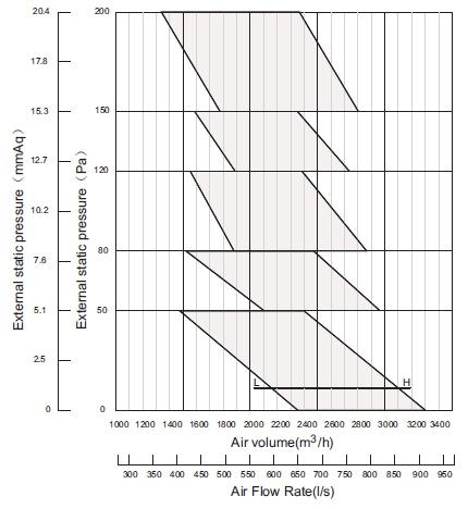
14 Access to condensate tray through access panel Access Panel 9. SYSTEM SETTINGS 9.1 The system capacity (power) and the fan speed settings (static pressure) are set on the Fan Coil Unit PCB. Capacity code setting - ENC1 The capacity of the indoor unit has been factory set in accordance with the table below. This setting must not be changed. Fig.8-2 Capacity code (DINLR07Z71 example) ENC1 8.3 Installing the outdoor unit drain Fit the seal into the drain joint, then insert the drain joint into o the base pan hole of the outdoor unit. Rotate it 90 to lock securely. Connect the drain joint to the drain pipe (field supplied) Drain to waste in accordance with local plumbing regulations. Drain is required to remove water produced during heating mode (Refer Fig.8-3) Fig.8-3 Table 9-1 ENC1 NOTE: The capacity has been factory set This setting must not be changed Toggle switch Model Code 4 DINLR05Z71 5 DINLR07Z71 7 DINLR09Z71 8 DINLR11Z71 9 DINLR14Z71 9 DINLR17Z71 Seal Drain joint The base pan hole of outdoor unit The base pan hole of outdoor unit Seal Drain joint 9.2 Fan speed setting - ENC2 The factory toggle switch setting for ENC2 is 0". Adjust the fan setting as required to suit the application. Refer to Tables 9-2, 9-3 & 9-4 for toggle switch settings Also refer to section 9-3 Fan performance charts for air quantity and static pressure information. Table 9-2 Fan Speed Setting - DINLR05Z71 13

15 Table 9-3 Fan Speed Setting - DINLR07Z71, DINLR09Z71 Table 9-4 Fan Speed Setting - DINLR11Z71, DINLR14Z71, DINLR17Z71 14
 DINLR07Z71 15")
16 9.3 Fan performance charts DINLR05Z71 - Mid Static Air Flow Rate (L/s) DINLR07Z71 15


17 DINLR09Z71 DINLR11Z71 16

18 DINLR14Z71 DINLR17Z71 17
19 10. REFRIGERATION CIRCUIT SCHEMATIC DIAGRAM m 11. WIRING CAUTION The system shall be installed in accordance with all local and national wiring regulations. The air conditioner shall use a separate power supply with adequately rated voltage. The external power supply to the air conditioner should be earthed appropriately. This earthing applies to both the indoor and outdoor units. All wiring should be carried out by suitably qualified and trained personnel in accordance with the circuit diagrams. A dedicated and appropriately sized circuit breaker must be used in accordance with local and national wiring standards. Be sure to separate t he power wiring and the control wiring sufficiently to avoid interference. Do not turn on the mains power until you have checked the wiring circuit carefully after wiring. NOTE Remark per EMC Directive 89/336/EEC To prevent wiring/control/interference issues during compressor start up, the following installation conditions apply The unit power supply must be connected directly to the mains power distribution board. The distribution supply must be of a low impedance, normally the required impedance requires a circuit breaker. No other equipment can be connected to this power circuit. For detailed installation compliance please refer to the local electricity supplier to see if there are any restrictions for this type of product. For electrical details of the unit please refer to the rating plate on the product. If you have any questions, please contact Brivis Service. If any wiring cables are damaged, they must be replaced by a suitably trained and qualified technician strictly in accordance with all local and national regulations. The appliance must be installed in strict accordance with all local and national wiring regulations. 18
20 11.1 Connecting the wiring cables Undo the screws of the access panel cover of the outdoor unit. Pull in the direction of the arrow to pull the access panel down and then out to remove the access panel. This allows access to the compressor compartment and electrical board. (Refer to Fig.11-1) Connect the appropriate cables to the terminals as identified with their respective matched numbers on the terminal blocks of indoor and outdoor units. Re-install the access panel. Access panel Electrical terminals 11.2 Power Specifications (Refer to Table 11-1) 11.3 Wiring Diagrams (Refer to Fig.11-2~Fig.11-3) Fig Outdoor Units Undo the screws of the access panel cover of the outdoor unit. Remove the access panel as required to gain access to electricals. NOTE Please be careful not to scratch the surface of the unit. NOTE All the pictures in this manual are indicative for explanation only. They may be different from the air conditioner supplied depending on the model. Actual dimensions should be reviewed. Fig.11-1 is indicative only, based on one type of outdoor unit. Actual unit supplied may be different. Power Specifications Table 11-1 INDOOR UNIT OUTDOOR UNIT TYPE Power Supply V-Ph-Hz Max. Input Current A Rated Input W Power Supply V-Ph-Hz SYSTEM 220~ ~ Max. Input Power W Max. Input Current A Min. Circuit Breaker Size A CAUTION An appropriately sized circuit breaker must be installed in accordance with all local and national wiring regulations. 19
21 Wiring circuit schematic diagram Fig Power ( V 50Hz) Power ( V 50Hz) Single Phase Single Phase Switch Power Wiring Indoor Indoor Unit Communication Cable Outdoor Unit Circuit Breaker Power Wiring Outdoor Wired Programmable Controller Programmable thermostat and interconnecting communication cables Fig CN40 CN29 CN28 P E Q ALARM E Y X Shield FIELD SUPPLIED 3 CORE SHIELDED CABLE INTERCONNECTING WIRING LOOM (6m) ON/OFF E Q P CDU WIRED PROGRAMMABLE CONTROLLER PART NO: B NOTE 20
22 12. TEST OPERATION The test operation must be carried out after the entire installation has been completed. Please confirm the following points before the test operation: The indoor unit and outdoor unit are installed properly. Refrigerant piping and wiring are correctly completed. The refrigerant pipe system is leak tested. Drains and drainage are clear and unimpeded. Pipe insulation is complete. The system has been earthed correctly. The length of the refrigerant pipe and any added refrigerant quantities have been recorded. The power and voltage of the site are alligned with the rating of the airconditioner. There are no obstacles impeding inlets or outlets of the outdoor or indoor units. The condensing unit suction and liquid isolation valves are both open. The crankcase heaters have been energised prior to start up. Test operation. Set the air conditioner t o "COOLING" mode with the controller, and check the following points of operation. 4 1) The indoor unit: a. Whether the switch on the controlle r is operational b. Whether the buttons on the controller work correctly. c. Whether the air flow is evident from the outlets. d. Whether the room temperature is set correctly. e. Whether the indicator lights are working normally. f. Whether the temporary button works correctly. g. Whether the condensate drain is running normally. h. Whether there is any vibration or abnormal noise during operation. i. Whether the air conditioner heats correctly in HEATING mode. 2) The outdoor unit: a. Whether there is any vibration or abnormal noise during operation. b. Air pathways on the inlet and outlet sides are free and unimpeded by any foreign matter or any obstacles. c. Whether any of the refrigerant has leaked. Once the system is fully commissioned, please discuss and advise the user on all aspects of the system including: a. Systems configuration and design conditions. b. Thermostat and controls operation. c. Maintenance requirements (filters, regular servicing) CAUTION An inbuilt protection feature prevents the unit from restarting for approximately 3 minutes immediately after it has been shut down. 21
23 13. OWNERS MANUAL USER GUIDE OPERATION, MAINTENANCE AND WARRANTY Welcome to high efficiency year-round comfort. Congratulations on your excellent choice and sound investment in a Brivis Ducted Reverse Cycle Inverter Home Comfort System. Please also take the time to read the contents of this Operating Manual, register your product warranty and retain this document for future reference. Your new Brivis system represents both the latest in engineering developments and the culmination of many years of experience by one of the most reputable manufacturers of home comfort systems. Your new unit is among the most reliable home comfort products available today. To achieve the performance and efficiency expected from your new system, please ensure the Installer is a qualified tradesperson, that the Installer has commissioned the unit and instructed you on its operation. To assure its dependability, spend just a few minutes with this booklet now. Learn about the operation of your system and the small amount of maintenance it takes to keep it operating at its peak efficiency. With minimal care, your Brivis system will provide you and your family with satisfying home comfort - both now and for many years to come. WARNING This appliance is not intended for use by persons (including children) with reduced physical, sensory or mental capabilities, or lack of experience and knowledge, unless they have been given supervision or instruction concerning use of the appliance by a person responsible for their safety. Children should be supervised to ensure that they do not play with the appliance. Do not place articles on or against this appliance Do not use or store flammable materials near this appliance Do not spray aerosols in the vicinity of this appliance while it is in operation Do not modify this appliance Improper installation, adjustment, alteration, service, maintenance, or use, can cause explosion, fire, electric shock, or other conditions which may cause personal injury or property damage. Refer to this document or and or other accompanying manuals. For assistance or additional information consult Brivis, a qualified installer or authorized service agency. The qualified installer or agency should use only factory authorised components or accessories if and when servicing this product. 22
24 Important Information To better protect your investment and to eliminate unnecessary service calls, please familiarise yourself with the following: Your ducted system should never be operated without a clean filter properly installed. Plan to inspect the filter periodically. A clogged filter will increase operating costs and shorten the life of the unit. Supply-air and return-air registers (grilles) should not be blocked or obstructed. Restricted airflow lessens the unit's efficiency and life span. Outdoor (condenser / compressor) units must have unrestricted airflow. Do not cover the unit, lean any thing against it, or stand upon it. Do not allow grass clippings, leaves, or other debris to accumulate around or on top of the unit. Maintain a minimum of 300mm clearance between the outdoor unit and tall grass, shrubs, vines etc. Your Thermostat / Controller is the control centre for your system. Please familiarise yourself with its specific operation, as the information following is of a general nature. Attempting to control the system by other means - for instance, switching the electrical supply power ON and OFF, may cause damage to the unit. Thermostat jiggling causes rapid-cycling, which is potentially dangerous to the compressor and may blow the protective fuse or circuit breaker device at the mains power supply. Do not adjust the temperature on the thermostat for any reason for at least five (5) minutes after the compressor has shut off. You may find that you can maintain greater personal comfort by running the FAN continuously. Air pockets can form due to the structure of the building, placement of registers etc. These air pockets may create cool or warm spots. Continuous FAN operation helps minimise any temperature differences. Systems equipped with electronic air cleaners or humidifiers accessories offer the added benefit of having the air continuously cleaned year round, and humidified during the winter season. Your system removes humidity from your home during the cooling season. The Indoor unit has a (primary) condensate connected to your drainage system; but an overflow (secondary) drain should also be installed. If water is observed in the overflow drain - it may be clogged, and your installer or Brivis should be contacted for inspection. Operating Your System The operation of your systems is controlled by the indoor Thermostat / Controller. Simply adjust the Controller to maintain the indoor temperature at the level you select, subject to it being within the design conditions of the system. Typical settings are 24 O C and 20 O C for Cooling and Heating respectively. The Brivis Inverter System will automatically modulate the outdoor unit capacity in response to the demand of the conditioned space, to help ensure rapid cool down or warm up times, as well as providing more constant temperature control. Please refer to the Operating Instructions accompanying your Thermostat / Controller. Cooling Cycle When operating in the COOL mode, your system will run until the indoor temperature is lowered to the level you have selected (within design conditions). On extremely hot days, your system will run for longer periods at a time and have shorter off periods than on moderate days. The following typical conditions add extra heat and/or humidity to your home causing your system to work longer to maintain comfortable conditions: Entrance (external) doors are frequently opened and closed Operating laundry appliances or running showers 23
25 More than the usual lights or electrical appliances operating More than the usual number of people Window furnishings open on sunny side of home System operating at or outside the original system design conditions as specified by your Installer Heating Cycle In HEAT mode, the system will provide warmth until the temperature is raised to the level you have selected. The unit will operate for longer periods to maintain a comfortable environment on colder days and nights than on moderate ones. Defrost Cycle: When the system provides heating to your home and the outdoor temperature drops below 7.2 O C, moisture may begin to freeze on the surface of the outdoor coil. If allowed to build up, this ice would impede the airflow across the coil and reduce the amount of heat absorbed from the outside air. To maintain energy efficient operation, your Brivis Heat Pump has an automatic defrost cycle. The defrost controls will automatically start when there is sufficient ice to interfere with normal heating operation. During defrost, the Indoor Fan will not be running. After the ice is melted, or after a maximum of 10 minutes in defrost mode, the unit will automatically resume normal heating operation. Do not be alarmed if steam or fog appears at the Outdoor Unit during the defrost cycle. Water vapour from the melting ice may condense into a mist in the cold outdoor air. Zoned Systems Some home comfort systems are designed to operate on a zoned basis only i.e. they are not designed to heat and or cool the entire home or space at one time. Generally, a zoned system will be designed by your Installer for your specific requirements. Your particular zoning configuration and the basis of design should be specified and detailed by your Installer. With zoned systems, always observe the following: The Return Air grille(s) are generally in the Common Zone, and need to be part of the conditioned space at all times Close off all doors to areas that are not being conditioned i.e. effectively isolate unconditioned spaces Set your zoning configuration with your zone controls before starting your Brivis system Do not attempt to shut down more zones than the minimum as specified by your installer, as this may lead to system shut down Do not attempt to heat or cool more zones than the maximum specified by your installer as this will prevent the system from being able to maintain design conditions NOTE: The type of zoned system you have will have been specified by your installer. This should include information on the total number of zones, the minimum and maximum number recommended to operate at one time to maintain design conditions, and the actual design conditions (Indoor Temperature Control settings at specified Outdoor Ambient conditions for both Heating and Cooling). Performing Routine Maintenance With proper maintenance and care, your Brivis system will operate economically and dependably. Maintenance can be accomplished easily by referring to the following general directions. However, before performing maintenance, consider these important safety precautions: DISCONNECT ALL ELECTRICAL POWER TO HEAT PUMP BEFORE REMOVING ACCESS PANELS TO PERFORM SERVICE OR MAINTENANCE NOTE: THERE MAY BE MORE THAN ONE ELECTRICAL ISOLATING SWITCH 24
26 ALTHOUGH SPECIAL CARE HAS BEEN TAKEN TO MINIMISE SHARP EDGES IN THE CONSTRUCTION OF YOUR UNIT, BE EXTREMELY CAREFUL WHEN HANDLING PARTS OR REACHING INTO THE UNIT Checking The Air Filter Filters are supplied and fitted by your installer and are not part of the Brivis system. A dirty air filter will cause excessive strain on the compressor and fan blower motor. This can cause the compressor to overheat and automatically shut down. In the extreme, the components will fail and will need to be replaced. To avoid inefficient or failed operation of your unit, CHECK THE FILTER AT LEAST EVERY 3 TO 4 WEEKS. Replace filters(s) when necessary, or clean them if they are the reusable type. Disposable filters should be replaced by similar, new filters of the same grade and dimensions. Reusable (permanent) type filters should be washed in a solution of cold to tepid water and very mild detergent, then rinsed and thoroughly dried. THE FILTER MUST BE COMPLETELY DRY BEFORE BEING REPLACED. To avoid prolonged shutdown of your system while a filter is being cleaned, you may wish to have an extra filter on hand. This would allow you to rotate between the two with minimal downtime for your comfort system. Extra filters are available from your Installer or a Brivis Spare Parts outlets. Should you have any questions about the removal and/or cleaning of you filter(s), PLEASE contact your Installer for assistance. If grass clippings, leaves, shrubbery and debris are kept away from the Outdoor Unit, minimal care should be sufficient to keep the system functioning properly. However, if the outdoor coil becomes dirty, use a soft brush or vacuum and soft brush attachment to clean the exterior surface. If dirt is trapped deep within the coil, contact your Installer or Brivis for service. Unit Support The indoor Fan Coil Unit (FCU) should be located in a position and in such a manner as specified in the Installation Instructions. The FCU should be maintained at a position that ensures condensate drainage from the unit. In an attic space, ideally the unit will be easily and safely accessible from the ceiling access panel, have a suitable catwalk and platform, and if necessary a service light. The outdoor Condensing Unit (CDU) requires adequate support to ensure it is level. CDUs generate condensate water in the heating mode; depending on local codes this may need to be discharged in a prescribed manner. Non Brivis Field Supplied Accessories Your home comfort system may include field-supplied accessories that do not form part of this regular maintenance cycle. These may include: ductwork, fittings, filters, grilles, zone motors, auxiliary heaters, third party controls and other non-brivis supplied items. These items may also require attention in accordance with the Original Equipment Manufacturer s (OEM) recommendations. Your installer can provide details in this regard, and should be consulted for any warranty or service matters for these items. Whilst they are an integral part of your home comfort system, these non- Brivis items are not covered by your Brivis Product Warranty. Third party controls and zoning systems that interfere with the correct operation of your Brivis Heat Pump system, and any consequential damages to Brivis equipment as a result of such incorrect operation, will not be covered by Brivis Warranty. 25
27 Service, Maintenance and Warranty To ensure continuing high performance and to minimise the possibility of premature equipment failure, periodic maintenance should be performed on the air conditioning equipment. It is recommended the unit be maintained by a qualified person as follows: The minimum maintenance requirements for this equipment are as follows: Monthly Inspect and clean Return Air Filters. Replace throwaway type filters when they become clogged with dust and lint or clean cleanable type filters monthly Yearly Inspect indoor coil, internal drip tray and condensate drain. Clean when necessary Inspect the heater s fan motor and wheel for cleanliness and alignment. Clean and align the motor assembly where applicable Inspect outdoor coil. Clean when necessary. Inspect the outdoor unit. Ensure air flow is not disturbed by any obstacle around it. Inspect outdoor fans and motors. Ensure that fan blades are clean and adequately balanced Inspect the unit cabinet and insulation for damage and corrosion. Repair where necessary. Check for vibration and excessive noise. Correct where necessary Inspect refrigerant tubing for oil accumulations. If oil is detected, leak test refrigerant tubing using an electronic leak detector or liquid soap solution Check refrigerant charge by measurement of superheat and sub cooling. Where necessary, adjust charge to achieve optimum performance Check the tightness of electrical connections Brivis Customer Care Program Brivis products are renowned for providing years of trouble free performance. To be at their most efficient performance, like most things, they need a little care. So to ensure that every Brivis unit is always in perfect condition we have established the Brivis Care Program for our valued customers. When you are a member of our Care Program you will receive a courtesy contact regarding maintenance service to your unit. This service includes cleaning the unit and ensuring that the system is operating at maximum efficiency. Not only does this guarantee peak performance, it also allows any minor problems to be detected early. This ensures that the system will always be ready when you need it. Brivis Customer Care Program Membership The Brivis Customer Care Program is designed to help you get the most out of your new unit. We may contact you before each winter or summer season with some preferential offers for preventative maintenance services which will keep your Brivis unit in great condition! Please note: Preventative Maintenance Services are chargeable and not covered under your product warranty. Your unit must have reasonable and safe access and be installed inline with the installation instructions supplied with the unit. An extra charge may apply if Brivis is required to allocate two service personnel to attend, in accordance with OH & S requirements. 26
28 Please register your warranty details on line at brivis.com.au For your records: Name _ Site Address State _Postcode Equipment Details: Model No (s) Indoor Outdoor Serial No (s) Indoor _ Outdoor Date of purchase / installation _ Installer Name _ Installer Contact Details Privacy Notification Brivis Climate Systems Pty Ltd is the registered owner of the Brivis brand. Brivis will collect "personal information from you when you complete your warranty and maintenance registration form. This personal information is collected under the guidance of the Privacy Information Protection Act The purpose of collecting this information is to: Process your request for us to provide service activities for you Register your purchase of equipment for warranty Register your request for a survey/quotation for Heating Ventilation Air Conditioning goods and services The intended recipients of the information are: Employees of Brivis Federal and State Governments who may require the information for administration purposes While the supply of the information by you is voluntary, if you cannot provide or do not wish to provide the information sought, Brivis may not be able to provide the services you request. If you have already provided information but have changed your mind and do not want the information used, you may make application for access or amendment for that information not to be used. You have a right of access to, and correction of, the information concerning yourself in accordance with the relevant procedures under the Act. Enquiries concerning this matter can be addressed to the Business Practices Officer of Brivis, who can be contacted on 1300 BRIVIS. Bonus offer when you register your product online brivis.com.au 27
29 Terms of Warranty Australia and New Zealand Brivis Climate Systems Pty. Ltd. ABN , AU Malcolm Rd, Braeside, VIC Definitions The terms listed below shall have the following meanings: 1. Authorised Service Representative means an independent service contractor authorised by Brivis or Brivis service personnel. 2. Brivis means Brivis Climate Systems Pty Ltd ABN and any related company. 3. Certificate(s) of Compliance means certificate(s) issued by licensed personnel including plumbers, refrigeration mechanics, electricians or other relevant trades people to certify that any prescribed works comply with applicable regulatory requirements. 4. Certificate(s) of Occupancy means certificate(s) issued by the local council which certifies that a home can be occupied. 5. Installation Site means the site at which the Product is originally installed. 6. Normal Business Hours means 8:30am to 5:00pm week days excluding public holidays. 7. Operating Instructions means the user manual or other documentation which provides detailed instructions on the proper operation and maintenance of the Product. 8. Other Applications means any Product used for non-residential and Light Commercial Applications. Other Applications may include but are not limited to factory, IT/Server room, telephone exchange, processing area (e.g. bakery, kitchen, warehouse, swimming pool, agricultural facilities such as a nursery) and any Product which has been installed, for whatever purpose as a retrofit component to an existing system. 9. Purchaser means the end user of the Product, the person named as owner in the Warranty certificate, the holder of the Proof of Purchase or the holder of a property transfer document where the Product is included as part of the chattels. 10. Product means the equipment purchased by the Purchaser and described in Section 2 of this document. 11. Proof of Purchase means a Tax Invoice or Receipt in respect of the Product. In the case of new constructions, a Certificate of Occupancy or a Certificate of Compliance that details the date of installation or commissioning will suffice. 12. Qualified Installer means the qualified installation contractor who is responsible for performing the installation work in the manner prescribed by local and statutory regulations, including compliance with any relevant Australian Standards, and to Brivis specifications. 13. Residential & Light Commercial Applications means any Product for use in both residential and light commercial applications. For example, homes, offices, hotels, apartments, nursing homes, hospitals, health care premises, shopping centres, and retail stores, where the Product is solely used for purpose of human comfort under standard operating conditions. 28
30 2. Terms of Warranty 2.1 Subject to the Terms of Warranty set out in this document, effective from the date of purchase by the Purchaser, the Product is warranted to be free from defects in materials and factory workmanship for the period set out in the table below: PRODUCT GROUP PARTS LABOUR Evaporative Coolers & Ducted Gas Heaters (excluding Compact Classic Series) 5 YEARS 5 YEARS Residential & Light Commercial Ducted Gas Heaters - Compact Classic Series 3 YEARS 3 YEARS Refrigerated Airconditioning Products 5 YEARS 5 YEARS Ducted Gas Heaters - Heat Exchangers & Burners Evaporative Coolers - Structural components only 10 YEARS N/A Other Applications All Product Groups 1 YEAR 1 YEAR Aftermarket Spare Parts 1 YEAR N/A 2.2 Brivis will determine in its sole discretion, which classification the Product fits into and the corresponding Warranty that shall apply. 2.3 An Authorised Service Representative will repair or replace, at its option, the Product or any part of the Product that its examination shows to be defective. The repair or replacement shall be performed during Normal Business Hours by an Authorised Service Representative. Repair by persons other than an Authorised Service Representative may void the Warranty. 2.4 The Warranty of the Product requires that, in addition to all other conditions, the Purchaser conducts regular and/or preventative maintenance as may be specified by Brivis (e.g. Operating Instructions) and required by the level of usage and the usage environment, including the use of correct and uncontaminated refrigerants and lubricants. 3. Conditions of Warranty 3.1 The Purchaser may only obtain the benefit of the Warranty if the Purchaser: a) maintains and services the Product in accordance with the instructions set out in the service section of the relevant Operating Instructions, Service or Owner s Manual; b) complies with clause Error! Reference source not found. below (titled "Purchaser's Responsibilities"); c) notifies Brivis within 30 days of a defect developing, that a claim is being made under this Warranty; and d) provides, in support of the claim made under this Warranty, a Proof of Purchase. 3.2 This document represents the only Warranty given by Brivis and no other person or organisation is authorised by Brivis to offer any alternative. 4. Exclusions 4.1 This Warranty does NOT cover: a) damage, problems or failure resulting from improper operation and/or inadequate maintenance by the Purchaser (refer Purchaser s Responsibilities section below); b) damage, problems or failure resulting from improper or faulty installation. The Product must be installed by a Qualified Installer in accordance with applicable regulations. Where applicable, 29
31 c) damage, problems or failure caused by factors external to the Product including, but not limited to, faulty or poor external electrical wiring, incorrect or faulty power supply, voltage fluctuations, over voltage transients or electromagnetic interference, inadequate or faulty gas, drainage services, or water services, including water pressure, and non potable water; d) damage, problems or failure caused by acts of God, fire, wind, lightning, flood, storm, vandalism, earthquake, war, civil insurrection, misuse, abuse, negligence, accident, pests, animals, pets, vermin, insects, spiders or entry of foreign objects or matter into the Product such as dirt, debris, soot or moisture; e) damage, problems or failure caused by weather including, but not limited to, hail, salt or other corrosive substances; f) Product which has been installed in a portable or mobile building, structure or application including, but not limited to, a caravan or boat; g) Product which is being re-installed at a location other than the original site; h) any consumable item supplied with the Product including, but not limited to, an air filter, battery, fan belt, igniter or cooler pad; i) installation of third-party components that may be attached to the Product. These include, but are not limited to, control wiring, ducting, return air filter(s) grille, register, diffuser, zone motors, controls/thermostats, pipe work and fabricated or added components. These items remain solely the responsibility of the Qualified Installer; j) installations where electrics/electronics may be subjected to moisture/chemicals (e.g. swimming pools or nurseries); k) any repair, which is needed as a result of an accident, misuse, abuse or negligence; l) Product that is utilised in an environment (indoor and outdoor) outside its specified operating range; and m) fair wear and tear to the Product. 5. Limitations 5.1 Product fitness for purpose and overall system design, sizing and application are not the responsibility of Brivis. This includes but is not limited to the heat load calculations, airflow and system balancing. 5.2 This Warranty does not apply to any Product installed at an Installation Site which is outside Australia or New Zealand. 5.3 Except where inconsistent with the purchaser s statutory rights and the rights given by this Warranty, all of the warranties and all liabilities of Brivis for any direct, special, indirect or consequential loss or damage, any damage or expense for personal injury or any loss or destruction of property arising directly or indirectly from the use or inability to use the Product or any of its parts and servicing the Product, are expressly excluded. 6. Travel, Transport & Access Costs 6.1 The Purchaser must pay freight charges, in-transit insurance expenses and travelling costs for repairs/replacements under this Warranty, that are required to be performed 100km or more from the nearest Brivis branch or Authorised Service Representative. 6.2 Subject to clause 6.3, Brivis will pay freight charges, in-transit insurance expenses and travelling costs for repairs/replacements that are required to be performed less than 100km from the nearest Brivis branch or Authorised Service Representative. In this circumstance: a) Brivis will arrange for such repairs/replacements and make any payment directly to the third party to provide the freight, in-transit insurance or travel services; or 30
32 b) if Brivis considers appropriate, it will authorise the Purchaser in writing to pay for the relevant freight charges, in-transit insurance expenses or travelling costs and then, upon provision by the Purchaser to Brivis of a tax invoice showing those costs have been incurred, reimburse the Purchaser for such costs which are within the terms of the authorisation. If the Purchaser pays for the relevant freight charges, in-transit insurance expenses or travelling costs without written authorisation from Brivis, Brivis will not reimburse the Purchaser for such costs. 6.3 The Purchaser must pay all costs and expenses in respect of: a) making the Product accessible for service. For example, restricted access or working at heights, or the labour cost for an additional person due to OHS requirements; b) providing a safe working environment for installation, service, maintenance or repair of the product; c) any surcharge applicable in respect of supplying replacement parts outside Normal Business Hours; and d) any other costs and expenses in relation to claiming the Warranty that is not covered by clause Purchaser s Responsibilities 7.1 The Purchaser must operate and maintain the Product in accordance with the Operating Instructions and service maintenance schedule, including conducting an appropriate number of services to the unit during the Warranty period, based on usage and the usage environment including but not limited to; a) regularly cleaning the air filter(s) and replacing them where necessary; b) replacing expired batteries or other consumables as required; c) ensuring that the condensate drain is kept clean and clear of obstructions; d) ensuring that outdoor units have unrestricted airflow and adequate clearances; e) ensuring that additional corrosion protection is applied to the Product if it is installed in a corrosive environment, for example, close to the sea. 8. Statutory Rights 8.1 The benefits given by this Warranty are in addition to other rights and remedies of the consumer under a law in relation to the goods or services to which the Warranty relates. 8.2 Australian purchasers have their benefit of statutory rights and nothing in these terms of Warranty has the effect of excluding, restricting or modifying those rights. Our goods come with guarantees that cannot be excluded under the Australian Consumer Law. You are entitled to a replacement or refund for a major failure and compensation for any other reasonably foreseeable loss or damage. You are also entitled to have the goods repaired or replaced if the goods fail to be of acceptable quality and the failure does not amount to a major failure. 8.3 For New Zealand purchasers nothing in these terms of Warranty is intended to limit the rights you may have under the Consumer Guarantees Act The Consumer Guarantees Act 1993 does not apply if the Product is acquired for the purpose of a business (as defined in the Act). Effective October 2013 For Australian Warranty Claims call 1300 Brivis ( ) or send to Brivis Warranty Claims 61 Malcolm Road, Braeside VIC For New Zealand Warranty Service call 0800 WARMAIR ( ) - Brivis only. The PURCHASER WILL BE CHARGED for work done or a service call(s) if:- the problem is not covered by these Terms of Warranty; there is nothing wrong with the product (e.g. instructing Purchaser on the operation of the Product and/or controls); or if the Purchaser is unable to provide Proof of Purchase validating that the Product is within the Warranty period. We recommend that you read the operating instructions, and in particular the troubleshooting section of the Operating Instructions, before you make a Warranty service call. Proof of Purchase must be presented. 31
33 NOTES 32
 Fax: +61 (03) 9264 9400 www.brivis.com.")
34 For all your Sales and Service enquiries call us on 1300 BRIVIS ( ) Brivis Australia 61 Malcolm Rd Braeside Victoria 3195 Australia 1300 BRIVIS ( ) Fax: +61 (03) Brivis New Zealand Distributor: Warm Air Ltd 69 Marsden Street Lower Hutt 5010 New Zealand PO Box Wellington Mail Centre Wellington 5043 New Zealand 0800 WARMAIR ( ) Ph: +64 (04) Fax: +64(04) Brivis South Africa Distributor: Lorenz and Associates Northlands Deco Park Cnr Witkoppen and Newmarket Roads North Riding, Johannesburg South Africa BRIVIS ( ) Ph: +27 (011) Fax: +27 (011) Brivis Climate Systems Pty. Ltd. All rights reserved. No part of these documents may be used in any way or form without prior written consent from Brivis Climate Systems Pty Ltd. Part Number: B November 2013 Brivis Climate Systems Pty. Ltd. ABN AU24752 Specifications subject to change without notice Brivis Climate Systems Pty. Ltd.
Packaged Air Conditioning Units. Owner s Guide to Operating and Maintaining Your Air Conditioner. This manual should be left with the owner.
 Packaged Air Conditioning Units Owner s Guide to Operating and Maintaining Your Air Conditioner ELECTRICAL SHOCK HAZARD. Failure to follow this warning could result in personal injury, Disconnect power
user s information manual
 user s information manual SINGLE PACKAGE ROOFTOP HEAT PUMP UNITS 664A 864A Sizes 024-048 Cancels: New OM02-55 5/1/96 NOTE TO INSTALLER: This manual should be left with the equipment owner. WARNING: Before
MODEL 598A TWO-SPEED PLUS CENTRAL AIR CONDITIONER
 USER S INFORMATION MANUAL MODEL 598A TWO-SPEED PLUS CENTRAL AIR CONDITIONER NOTE TO INSTALLER: This manual must be left with the equipment user. WELCOME TO EFFICIENT HOME COOLING COMFORT Congratulations
Brivis Ducted Reverse Cycle Inverter. Installation Manual. Please read this manual carefully prior to installation
 Brivis Ducted Reverse Cycle Inverter Installation Manual Please read this manual carefully prior to installation CONTENTS PAGE PRES... INSTALLATION INFORMATION... ACCESSORIES... 3 INSPECTING AND HANDLING
Installation and Operation Manual. CMA12SB-0 Series. Horizontal/Side Discharge Condensing Units
 Installation and Operation Manual CMA12SB-0 Series Horizontal/Side Discharge Condensing Units 517.787.2100 www.marsdelivers.com www.heatcontroller.com Heat Controller CONTENTS PAGE 1. PRES... 1 2. INSTALLATION
CENTRAL AIR CONDITIONER
 USER S INFORMATION MANUAL CENTRAL AIR CONDITIONER NOTE TO INSTALLER: This manual must be left with the equipment user. WELCOME TO EFFICIENT HOME COOLING COMFORT Congratulations on your excellent choice
HEAT PUMP A GUIDE TO OPERATING AND MAINTAINING YOUR RESIDENTIAL HEAT PUMP UNIT NOTE TO INSTALLER: THIS MANUAL SHOULD BE LEFT WITH THE EQUIPMENT USER.
 HEAT PUMP A GUIDE TO OPERATING AND MAINTAINING YOUR RESIDENTIAL HEAT PUMP UNIT NOTE TO INSTALLER: THIS MANUAL SHOULD BE LEFT WITH THE EQUIPMENT USER. WELCOME TO EFFICIENT YEAR-ROUND COMFORT Congratulations
INSTALLATION MANUAL COMFORT...BUILT TO LAST. 9,000, 12,000 and 18,000 BTU SINGLE-ZONE DUCTLESS MINI-SPLIT SYSTEM Heat Pump
 COMFORT...BUILT TO LAST 9,000, 12,000 and 18,000 BTU SINGLE-ZONE DUCTLESS MINI-SPLIT SYSTEM Heat Pump INSTALLATION MANUAL INDOOR UNIT: 1PAMSH09-SZW-14.5 1PAMSH09-SZW-15 1PAMSH12-SZW-15 1PAMSH18-SZW-15
INSTALLATION MANUAL. Split-type Air Conditioner (Cooling and Heating) Indoor Unit AQB18J6WC AQB24J2WC. Outdoor Unit UQB18J6WC UQB24J2WC
 Indoor Unit AQB18J6WC AQB24J2WC. Outdoor Unit UQB18J6WC UQB24J2WC") AQB8J6WC_IM_E_25864 2006.4.4 3:29 PM Page 7 INSTALLATION MANUAL Indoor Unit AQB8J6WC AQB24J2WC Outdoor Unit UQB8J6WC UQB24J2WC ENGLISH FRANÇAIS ESPAÑOL Split-type Air Conditioner (Cooling and Heating)
AQB8J6WC_IM_E_25864 2006.4.4 3:29 PM Page 7 INSTALLATION MANUAL Indoor Unit AQB8J6WC AQB24J2WC Outdoor Unit UQB8J6WC UQB24J2WC ENGLISH FRANÇAIS ESPAÑOL Split-type Air Conditioner (Cooling and Heating)
INSTALLATION MANUAL. Split-type Air Conditioner (Cooling and Heating) Outdoor Unit UQB09JJWC UQB12JJWC. Indoor Unit AQB09JJWC AQB12JJWC
 Outdoor Unit UQB09JJWC UQB12JJWC. Indoor Unit AQB09JJWC AQB12JJWC") AQB09JJ6WC_IM_E_2585 2006.4.17 4:26 PM Page 17 INSTALLATION MANUAL Indoor Unit AQB09JJWC AQB12JJWC Outdoor Unit UQB09JJWC UQB12JJWC ENGLISH FRANÇAIS ESPAÑOL Split-type Air Conditioner (Cooling and Heating)
AQB09JJ6WC_IM_E_2585 2006.4.17 4:26 PM Page 17 INSTALLATION MANUAL Indoor Unit AQB09JJWC AQB12JJWC Outdoor Unit UQB09JJWC UQB12JJWC ENGLISH FRANÇAIS ESPAÑOL Split-type Air Conditioner (Cooling and Heating)
INVERTER SPLIT - TYPE
 INVERTER SPLIT - TYPE ISSUE No 2 DATE 04/09/08 P/No 2020323A2868 CONTENTS SAFETY PRECAUTIONS Warning 2 Operating temperature 2 BEFORE INSTALLATION Tools needed for installation 3 Items required for installing
Horizontal/Side Discharge Condensing Units
 INSTALLATION, OPERATION & MAINTENANCE MANUAL Horizontal/Side Discharge Condensing Units Models CMA12SD-0 CMA18SD-1 CMA24SD-1 CMA30SD-1 CMA36SD-1 CMA48SD-1 517.787.2100 www.marsdelivers.com Horizontal/Side
DLCLRA. INSTALLATION INSTRUCTIONS Outdoor Unit Single Zone Ductless System Sizes 36 to 58 TABLE OF CONTENTS
 DLCLRA INSTALLATION INSTRUCTIONS Outdoor Unit Single Zone Ductless System Sizes 36 to 58 Fig. 1 - Size 36 TABLE OF CONTENTS PAGE SAFETY CONSIDERATIONS... 2 PARTS LIST... 3 SYSTEM REQUIREMENTS... 4 WIRING...
SINGLE - ZONE Ductless Split System Heat Pumps Installation, Operation & Maintenance Manual
 Presents SINGLE - ZONE Ductless Split System Heat Pumps Installation, Operation & Maintenance Manual 9k,12k 18k 24k, 30k, 36k ECR International, Inc. 2201 Dwyer Avenue, Utica NY 13501 Phone: 800.325.5479
Installation Instructions
 38MHR Outdoor Unit Single Zone Ductless System Sizes 09 to 24 Installation Instructions NOTE: Read the entire instruction manual before starting the installation. NOTE: Images are for illustration purposes
R32. Installation Manual Split Type Wall Mounted Air Conditioner. This appliance shall be installed in accordance with: REFRIGERANT
 SWING LRSWING Installation Manual Split Type Wall Mounted Air Conditioner COOL RUN C SPEED TURBO ON/OFF FAN COOL HEAT SWING SWING Rinnai Systems Models System Indoor Outdoor HSNRQ25B HINRQ25B HONRQ25B
NOTE TO EQUIPMENT OWNER:
 Owner s Information Manual Heat Pump System NOTE TO EQUIPMENT OWNER: For your convenience, please record the model and serial numbers of your new equipment in the space provided. This information, along
Packaged Heat Pumps. Owner s Guide to Operating and Maintaining Your Heat Pump
 Packaged Heat Pumps Owner s Guide to Operating and Maintaining Your Heat Pump NOTE TO EQUIPMENT OWNER: For your convenience, please record the model and serial numbers of your new equipment in the spaces
BR342 Ducted Installation Instructions Australian Version Electronic Wall Control
 Australian Version Electronic Wall Control 1 Introduction The BR342 reverse cycle rooftop air-conditioner is designed for installation onto Recreational Vehicles (RV s) at the time of manufacture or as
TABLE OF CONTENTS. NOTE: Read the entire instruction manual before starting the installation. TROUBLESHOOTING... 13
 R 410A Duct Free Split System Air Conditioner and Heat Pump Product Family: DFS4(A/H) System, DFC4(A/H)3 Outdoor, DFF4(A/H)H Indoor NOTE: Read the entire instruction manual before starting the installation.
QUICK CONNECT INSTALLATION MANUAL DUCTLESS MINI-SPLIT SYSTEM FOR MODELS: 2PAMSHQC12 2PAMSHQC18 2PAMSHQC24 2PAMSHQC36
 QUICK CONNECT DUCTLESS MINI-SPLIT SYSTEM INSTALLATION MANUAL FOR MODELS: 2PAMSHQC12 2PAMSHQC18 2PAMSHQC24 2PAMSHQC36 Before using your air conditioner, please read this manual carefully and keep it for
Fig. 1 - Unit PHD4 and WPH4
 OWNER S MANUAL 14 SEER Single -Package Heat Pump System with R -410A Refrigerant Single Phase and Three Phase 2 to 5 Nominal Tons PHD4 Series F and WPH4 Series B Fig. 1 - Unit PHD4 and WPH4 A09034 NOTE
Split Air Conditioner
 Change for Life Split Air Conditioner Installation Manual Residential Air Conditioners MODEL: GWC09AB-D3DNA2D GWC12AB-D3DNA2D GWC18AC-D3DNA2D GWC24AC-D3DNA2D GWH09AB-D3DNA2D GWH12AB-D3DNA2D GWH18AC-D3DNA2D
INSTALLATION INSTRUCTIONS TXV Horizontal Slab Coils WLSH
 TXV Horizontal Slab Coils WLSH These instructions must be read and understood completely before attempting installation. It is important that the Blower and Duct System be properly sized to allow the system
Owner s Information Manual
 50EZ---A and 50VT ---A Comfort and Performance 13 and 14 SEER Single Packaged Heat Pump System With PuronR (R ---410A) Refrigerant Single and Three Phase 2---5 Nominal Tons (Sizes 24---60) Owner s Information
AOYG18LFC OUTDOOR UNIT INSTALLATION MANUAL INSTALLATION MANUAL. For authorized service personnel only. PART NO
 AOYG8LFC OUTDOOR UNIT INSTALLATION MANUAL INSTALLATION MANUAL For authorized service personnel only. English PART NO. 93778639 93778639_IM.indb /20/20 6:07:25 PM AIR CONDITIONER OUTDOOR UNIT INSTALLATION
Central Air Conditioning System
 Owner s Information Manual Central Air Conditioning System NOTE TO EQUIPMENT OWNER: For your convenience, please record the model and serial numbers of your new equipment in the spaces provided. This information,
INSTALLATION INSTRUCTIONS TXV Horizontal Duct Coils EHD
 TXV Horizontal Duct s EHD These instructions must be read and understood completely before attempting installation. It is important that the Blower and Duct System be properly sized to allow the system
DLCSRA. INSTALLATION INSTRUCTIONS Outdoor Unit Ductless Split System Sizes 09 to 36 TABLE OF CONTENTS
 DLCSRA INSTALLATION INSTRUCTIONS Outdoor Unit Ductless Split System Sizes 09 to 36 NOTES: Read the entire instruction manual before starting the installation. Images are for illustration purposes only.
INSTALLATION INSTRUCTIONS TXV Horizontal Duct Coils EHD
 TXV Horizontal Duct s EHD These instructions must be read and understood completely before attempting installation. It is important that the Blower and Duct System be properly sized to allow the system
[FLARE CONNECTION TYPE] ATTENTION
![[FLARE CONNECTION TYPE] ATTENTION](/thumbs/88/117511702.jpg "[FLARE CONNECTION TYPE] ATTENTION") SPLIT-TYPE AIR CONDITIONERS Model MXZ-2A20NA [FLARE CONNECTION TYPE] HFC utilized R410A INSTALLATION MANUAL ATTENTION This manual mentions how to install only the outdoor unit, MXZ-2A20NA. As for the way
SPLIT-TYPE AIR CONDITIONERS Model MXZ-2A20NA [FLARE CONNECTION TYPE] HFC utilized R410A INSTALLATION MANUAL ATTENTION This manual mentions how to install only the outdoor unit, MXZ-2A20NA. As for the way
FOR SLIM DUCT/CEILING TYPE
 INSTALLATION MANUAL AIR CONDITIONER FOR SLIM DUCT/CEILING TYPE For correct installation, read this manual before starting installation. This manual may be subject to change without notice for purpose of
Split-type Air-Conditioner INSTALLATION MANUAL CONTENTS FOR INSTALLER MXZ-3B54VA MXZ-4B71VA. English
 Split-type Air-Conditioner MXZ-3B54VA MXZ-4B71VA INSTALLATION MANUAL English Refer to the installation manual of each indoor unit for indoor unit installation. IMPORTANT NOTES TO COMPLY WITH THE REQUIREMENTS
Installation Manual. KS Series KS09 KS12 KS18 KS24 KS28. J3387_Kaden_Installer_Manual_ indd 1
 Wall Mounted AIR CONDITIONER Installation Manual KS Series KS09 KS12 KS18 KS24 KS28 J3387_Kaden_Installer_Manual_050917.indd 1 5/09/2017 9:07 AM J3387_Kaden_Installer_Manual_050917.indd 2 5/09/2017 9:07
ROOM AIR CONDITIONER INSTALLATION MANUAL
 ROOM AIR CONDITIONER INSTALLATION MANUAL (Inverter Split Type) Please read this installation manual completely before installing the product When the power cord is damaged, replacement work shall be performed
Installation Instructions
 40MBFQ Floor Console Ductless System Sizes 09 to 58 Installation Instructions TABLE OF CONTENTS PAGE SAFETY CONSIDERATIONS... 2 PARTS LIST... 3 SYSTEM REQUIREMENTS... 4 WIRING... 4 DIMENSIONS... 5 CLEARANCES...
CENTRAL AIR CONDITIONER SPLIT SYSTEM
 CENTRAL AIR CONDITIONER SPLIT SYSTEM WITH ELECTRONIC CONTROL SERIES: DS INSTALLATION INSTRUCTIONS INDEX GENERAL... 2 UNIT LOCATION CRITERIA... 2 DIMENSIONAL DRAWINGS... 3 INDOOR UNIT INSTALLATION... 5
Installation Instructions
 8GXM / 0GXM Multi---Split High---Wall Duct Free Split System 8GXM --- Size 18k, k, and 0k 0GXM --- Size 9k, 1k, and 18k Installation Instructions NOTE: Read the entire instruction manual before starting
HEAT PUMP INSTALLATION MANUAL
 DUCTLESS INVERTER HEAT PUMP INSTALLATION MANUAL Models: TERRA09HP230V1A TERRA12HP230V1A TERRA18HP230V1B TERRA24HP230V1B Thank you for choosing a Gree Terra Ductless Heat Pump for your customer. Please
Mini-Split Air Conditioner
 Cassette Type Installation Manual New Released A-Cassette-600 Mini-Split Air Conditioner DC Inverter Cassette Type Unit All Model Numbers Table of Contents Installation Manual 2 3 Accessories... 04 Safety
Mortex INSTALLATION INSTRUCTIONS AIR CONDITIONING & HEAT PUMP INDOOR COILS
 Mortex INSTALLATION INSTRUCTIONS AIR CONDITIONING & HEAT PUMP INDOOR COILS INTRODUCTION Please note that HUD Manufactured Home Construction and Safety Standard Section 3280.714, paragraph (a) and subparagraph
General safety precautions English
 English A min (m 2 ) 550 530 540 510 520 490 500 470 480 450 460 430 440 410 420 390 400 370 380 350 360 330 340 310 320 290 300 270 280 250 260 230 240 210 220 190 200 170 180 150 160 130 140 110 120
General safety precautions English
 English A min (m 2 ) 550 530 540 510 520 490 500 470 480 450 460 430 440 410 420 390 400 370 380 350 360 330 340 310 320 290 300 270 280 250 260 230 240 210 220 190 200 170 180 150 160 130 140 110 120
Ductless Split Air Conditioner
 Ductless Split Air Conditioner Installation Manual Indoor HSU09VHG(DB)-W HSU12VHG(DB)-W HSU18VHH(DB)-W HSU24VHG(DB)-W Outdoor HSU09VHG(DB)-G HSU12VHG(DB)-G HSU18VHH(DB)-G HSU24VHG(DB)-G Table of Contents
Inverter Air Conditioner Installation Manual GIN 090/GIN 091 GIN 120/GIN 121 GIN 180/GIN 181 GIN 240/GIN 241
 Inverter Air Conditioner Installation Manual GIN 090/GIN 091 GIN 120/GIN 121 GIN 180/GIN 181 GIN 240/GIN 241 Please read this user manual first! Dear Customer, Thank you for preferring a Beko product.
INSTALLATION INSTRUCTIONS Cased N Coil, Horizontal ENH4X
 INSTALLATION INSTRUCTIONS Cased N Coil, Horizontal ENH4X NOTE: Read the entire instruction manual before starting the installation. TABLE OF CONTENTS PAGE SAFETY CONSIDERATIONS... 1 INTRODUCTION... 1 INSTALLATION...
Bar Fridge USER MANUAL MB46W
 Bar Fridge USER MANUAL MB46W CONTENTS Safety information... 2-3 Identifying parts of the fridge... 4 Transporting... 5 Installation... 5 Reversing the door... 6 Operating instructions... 7 Cleaning &
DUCTED AIR CONDITIONER. Owner s Manual. KD Series KD24. Kaden Owner s Manual 1
 DUCTED AIR CONDITIONER Owner s Manual KD Series KD24 Kaden Owner s Manual 1 Table of Contents 1. Safety Precautions 4 2. Indoor Unit Parts and Major Functions 6 3. Care and Maintenance 8 4. Troubleshooting
Owner s Manual CMC100 Dehumidifier
 Owner s Manual CMC100 Dehumidifier DRI-EAZ PRODUCTS, INC. 15180 Josh Wilson Road, Burlington, WA 98233 Phone: 800-932-3030 Fax: (360) 757-7950 http://cmc-100.dri-eaz.com The CMC100 automatically controls
Choosing the installation site. Installation. 07 Choosing the installation site
 Installation Installation warnings: 1. Carefully read the installation manual before beginning. 2. Follow each step as shown. 3. Observe all local, state, and national electrical codes and by qualified,
Installation Instructions
 38MPRA Outdoor Unit Single Zone Ductless System Sizes 09 to 12 Installation Instructions NOTES: Read the entire instruction manual before starting the installation. Images are for illustration purposes
FDT11 FDT15 FDT18. DUCTED TYPE SPLIT SYSTEMS (3 Phase, Fixed Speed)
") OPERA TION & I NSTALLAT I O N FDT11 FDT15 FDT18 MANUAL DUCTED TYPE SPLIT SYSTEMS (3 Phase, Fixed Speed) Read this operating & installation instruction carefully and keep it for future reference DUCTED
OPERA TION & I NSTALLAT I O N FDT11 FDT15 FDT18 MANUAL DUCTED TYPE SPLIT SYSTEMS (3 Phase, Fixed Speed) Read this operating & installation instruction carefully and keep it for future reference DUCTED
RV Products Division INSTALLATION INSTRUCTIONS FOR SERIES PACKAGE AIR CONDITIONER
 RV Products Division INSTALLATION INSTRUCTIONS FOR 46413 SERIES PACKAGE AIR CONDITIONER 1. WARNINGS IMPORTANT NOTICE These instructions are for the use of qualified individuals specially trained and experienced
CONTENTS INSTALLATION MANUAL HFC FOR INSTALLER R410A. utilized 1. THE FOLLOWING SHOULD ALWAYS BE OBSERVED FOR SAFETY... 2
 SPLIT-TYPE AIR CONDITIONER CONTENTS INSTALLATION MANUAL 1. THE FOLLOWING SHOULD ALWAYS BE OBSERVED FOR SAFETY... 2 Model MXZ-A26/32WV HFC utilized R410A 2. INSTALLATION DIAGRAM & ACCESSORIES... 2 3. SELECTING
Owner s Manual CMC100 Dehumidifier
 Owner s Manual CMC100 Dehumidifier DRI-EAZ PRODUCTS, INC. 15180 Josh Wilson Road, Burlington, WA 98233 Phone: 800-932-3030 Fax: (360) 757-7950 http://cmc-100.dri-eaz.com The CMC100 automatically controls
Installation Instructions
 40MBD Ducted Style Ductless System Sizes 09 to 48 Installation Instructions NOTE: Read the entire instruction manual before starting the installation. TABLE OF CONTENTS PAGE SAFETY CONSIDERATIONS... 2
INSTALLATION INSTRUCTIONS Cased N Coil, Horizontal ENH4X
 INSTALLATION INSTRUCTIONS Cased N Coil, Horizontal ENH4X NOTE: Read the entire instruction manual before starting the installation. TABLE OF CONTENTS PAGE SAFETY CONSIDERATIONS... 1 INTRODUCTION... 1 INSTALLATION...
SPECTRACOOL Air Conditioner. N21 Model INSTRUCTION MANUAL nvent Rev. G P/N
 SPECTRACOOL Air Conditioner N21 Model INSTRUCTION MANUAL Rev. G P/N 89115088 TABLE OF CONTENTS WARRANTY AND RETURN POLICY...2 RECEIVING THE AIR CONDITIONER...3 HANDLING AND TESTING THE AIR CONDITIONER...3
Installation Manual. Ceiling & Floor Type CEILING & FLOOR TYPE AIR CONDITIONER
 CEILING & FLOOR TYPE AIR CONDITIONER Installation Manual Ceiling & Floor Type IMPORTANT NOTE: Read this manual carefully before installing or operating your new air conditioning unit. Make sure to save
Installation Instructions
 38MGQ Multi-Zone Ductless System Sizes 18, 27, 36 and 48 Installation Instructions NOTE: Read the entire instruction manual before starting the installation. TABLE OF CONTENTS PAGE SAFETY CONSIDERATIONS...
INSTALLATION MANUAL SPLIT TYPE ROOM AIR CONDITIONER (PART NO )
") SPLIT TYPE ROOM AIR CONDITIONER INSTALLATION MANUAL (PART NO. 9312791019-01) This air conditioner uses new refrigerant HFC (R410A). The basic installation work procedures are the same as conventional refrigerant
SPLIT TYPE ROOM AIR CONDITIONER INSTALLATION MANUAL (PART NO. 9312791019-01) This air conditioner uses new refrigerant HFC (R410A). The basic installation work procedures are the same as conventional refrigerant
Installation Instructions T 9822 Gas Dryer. en - US, CA. To prevent accidents
 Installation Instructions T 9822 Gas Dryer To prevent accidents en - US, CA and appliance damage read these instructions before installation or use. M.-Nr. 07 431 110 2 WARNING For your safety the information
Owner s Manual. Middle Static Pressure Duct Type MEU-18MPH2 MEU-24MPH2 MEU-36MPL2 MEU-48MPL2 MIDDLE STATIC PRESSURE DUCT TYPE AIR CONDITIONER
 MIDDLE STATIC PRESSURE DUCT TYPE AIR CONDITIONER Owner s Manual Middle Static Pressure Duct Type MEU-18MPH2 MEU-24MPH2 MEU-36MPL2 MEU-48MPL2 IMPORTANT NOTE: Read this manual carefully before installing
Installation manual for room air conditioner
 Installation manual for room air conditioner HSU-26HEK03/R2(D)/I HSU-35HEK03/R2(D)/I HSU-53HEK03/R2(D)/I HSU-71HEK03/R2(D)/I HSU-26HEK03/R2(D)/O HSU-35HEK03/R2(D)/O HSU-53HEK03/R2(D)/O HSU-71HEK03/R2(D)/O
Fig. 1 - Unit PGD4, PGS4, WPG4
 OWNER S MANUAL 14 SEER Single -Package Air Conditioner and Gas Furnace System with R -410A Refrigerant Single Phase 2 to 5 Nominal Tons Three Phase 3 to 5 Nominal Tons PGD4andPGS4SeriesE,WPG4SeriesB Fig.
Installation Instructions
 40MBFQ Floor Console Ductless System Sizes 09 to 12 Installation Instructions TABLE OF CONTENTS PAGE SAFETY CONSIDERATIONS... 2 PARTS LIST... 3 SYSTEM REQUIREMENTS... 4 DIMENSIONS... 5 CLEARANCES... 5
Installer manual AG-AA10. Air/air heat pump IHB GB AG-AA10-30 AG-AA10-40/50
 -30 Installer manual Air/air heat pump -40/50 IHB GB 1516-1 331554 Table of Contents 1 Important information 2 5 Installation 7 Safety information 2 Model combinations 7 Read before starting the installation
T-SERIES Air Conditioner. T20 Model INSTRUCTION MANUAL nvent Rev. C P/N
 T-SERIES Air Conditioner T20 Model INSTRUCTION MANUAL Rev. C P/N 89114993 TABLE OF CONTENTS Warranty and Return Policy... 2 IMPORTANT NOTICE... 2 RECEIVING THE AIR CONDITIONER... 3 HANDLING AND TESTING
WMHP Series R410a Heat Pump INSTALLATION INSTRUCTIONS
 WMHP Series R410a Heat Pump INSTALLATION INSTRUCTIONS **WARNING TO INSTALLER, SERVICE PERSONNEL AND OWNER** Altering the product or replacing parts with non authorized factory parts voids all warranty
DAIKIN AIR CONDITIONER
 3P226011-1A M07B242A DAIKIN AIR CONDITIONER Two-dimensional bar code is a code for manufacturing. Safety Precautions (1) Read these Safety Precautions carefully to ensure correct installation. This manual
Installation Manual Super-Slim Four-Way Cassette
 Installation Manual Super-Slim Four-Way Cassette Models: MCOVT S / MROVT AS IMPORTANT NOTE: Read this manual carefully before installing or operating your new air conditioning unit. Make sure to save this
FAN COIL USER MANUAL TC18C2DWB1 TC24C2DWB1 TC37C2DWB1 TC48C2DWB1 TC60C2DWB Innovair Corporation. All Rights Reserved.
 FAN COIL USER MANUAL TC18C2DWB1 TC24C2DWB1 TC37C2DWB1 TC48C2DWB1 TC60C2DWB1 Duct Type 1. Features...7 2. Dimensions...8 3. Service Space...9 4. Wiring Diagrams...10 5. Capacity Tables...11 6. Capacity
USER S, MAINTENANCE and SERVICE INFORMATION MANUAL
 CONTENTS SAFETY INFORMATION................ 2 FOR YOUR SAFETY....................... 2 SYSTEM OPERATION.................. 2 THERMOSTATS.......................... 2 INTERMITTENT IGNITION DEVICE...........
Installation Instructions
 40MAQ High Wall Ductless Split System Sizes 09 to 36 Installation Instructions NOTE: Read the entire instruction manual before starting the installation TABLE OF CONTENTS PAGE SAFETY CONSIDERATIONS 2 PARTS
Installation Instructions
 Evaporator Coil A Coil --- Cased Multipoise NOTE: Read the entire instruction manual before starting the installation. TABLE OF CONTENTS PAGE SAFETY CONSIDERATIONS... 1 INTRODUCTION... 1 INSTALLATION...
Owner s Manual SPLIT-TYPE ROOM AIR CONDITIONER
 Owner s Manual SPLIT-TYPE ROOM AIR CONDITIONER IMPORTANT NOTE: Read this manual carefully before installing or operating your new air conditioning unit. Make sure to save this manual for future reference.
G-10f/GCG-10f UPRIGHT COOLER
 G-Series Cooler G-10f/GCG-10f UPRIGHT COOLER Manual is for the following models: G-10F, G-10-F33EB GCG-10F, GCG-10-F33EB GCG-10F2, GCG-10-F233EB G-10-F33EB-HC, GCG-10-F33EB-HC GCG-10-F233EB-HC Instruction
NEXXOS INVERTER USER MANUAL
 NEXXOS INVERTER USER MANUAL NIN412C2V32 NIN415C2V32 NIN520C2V32 NIN725C2V32 INVERTER MINI SPLIT SYSTEM WARNING The information contained in the manual is intended for use by a qualified service technician
CLIM9000CE PORTABLE AIR CONDITIONER USER MANUAL
 CLIM9000CE PORTABLE AIR CONDITIONER USER MANUAL Please read this user manual before using this innovative Air Conditioner and keep it safe for future reference. SAFETY INSTRUCTIONS Important! Carefully
Brivis Inverter Icebox
 Brivis Inverter Icebox R410A INSTALLATION INSTRUCTIONS PLEASE READ THESE INSTRUCTIONS CAREFULLY BEFORE INSTALLING & USING THIS PRODUCT Bonus offer when you register your product online brivis.com.au Table
INVERTER ONE-TWO/ONE-THREE/ONE-FOUR/ONE-FIVE SPLIT-TYPE AIR CONDITIONER
 INVERTER ONE-TWO/ONE-THREE/ONE-FOUR/ONE-FIVE SPLIT-TYPE AIR CONDITIONER Installation Manual IMPORTANT NOTE: Read this manual carefully before installing or operating your new air conditioning unit. Make
Please read this manual carefully before installation and keep it for future reference. CONTENTS. Installation Manual. DIY Series
 Please read this manual carefully before installation and keep it for future reference. CONTENTS Installation Manual DIY Series The design and specifications are subject to change without prior notice.
15,000 BTU Portable Air Conditioner
 Instruction Manual 15,000 BTU Portable Air Conditioner Model: HYAC15 READ AND SAVE THESE INSTRUCTIONS Please read and follow the instructions in this user manual even if you feel you are familiar with
INSTALLATION INSTRUCTIONS Cased N Coil, Horizontal ENH4X
 INSTALLATION INSTRUCTIONS Cased N, Horizontal ENH4X NOTE: Read the entire instruction manual before starting the installation. SAFETY CONSIDERATIONS Improper installation, adjustment, alteration, service,
Bosch Split-Type Ductless Air Conditioner / Heat Pump
 Bosch Split-Type Ductless Air Conditioner / Heat Pump Climate 5000 AA Series User Manual 2 Bosch Split Type Ductless Air Conditioner / Heat Pump User Manual Data subject to change 01.2017 Bosch Thermotechnology
DAIKIN ROOM AIR CONDITIONER. Operation Manual
 DAIKIN ROOM AIR CONDITIONER Operation Manual FDXM25F2V1B FDXM50F2V1B FDXM35F2V1B FDXM60F2V1B CONTENTS READ BEFORE OPERATION Safety precautions... 2 Names of parts... 4 CARE Care and Cleaning... 6 TROUBLE
GCG-10. Instruction Manual. G-Series Cooler. Manual is for the following models: GCG-10-N33EB G-10-N33EB UPRIGHT COOLER
 G-Series Cooler GCG-10 UPRIGHT COOLER Manual is for the following models: GCG-10-N33EB G-10-N33EB Instruction Manual Manual is for the following models: GCG-10-N33EB G-10-N33EB Instruction Manual GCG-10
CROWN. Boiler Co. Santa-Fe Series. Hydronic Air Handlers INSTALLATION, OPERATION & MAINTENANCE INSTRUCTIONS
 CROWN Boiler Co Santa-Fe Series Hydronic Air Handlers INSTALLATION, OPERATION & MAINTENANCE INSTRUCTIONS These instructions must be affixed on or adjacent to the air handler Models: SAC049A20 SAC059A25
Owner s Information Manual
 48ES---A and 48VL---A Comfort and Performance 13 and 14 SEER Single Packaged Air Conditioner and Gas Furnace System With Puron (R---410A) Refrigerant Single and Three Phase 2---5 Nominal Tons (Sizes 24---60)
SPLIT-TYPE ROOM AIR CONDITIONER
 Before using your air conditioner, please read this manual carefully and keep it for future reference SPLIT-TYPE ROOM AIR CONDITIONER Please read this installation manual completely before installing the
MXZ-4B80VA MXZ-5B100VA INSTALLATION MANUAL
 Split-type Air-Conditioner MXZ-4B80VA MXZ-5B100VA INSTALLATION MANUAL Refer to the installation manual of each indoor unit for indoor unit installation. English Deutsch Français Nederlands Español Italiano
INSTALLATION AND USER S MANUAL COOKER HOOD RS-600/A-S
 INSTALLATION AND USER S MANUAL COOKER HOOD RS-600/A-S RS-600 (CHS60SS)-GB-05.indd 1 6/8/2010 9:30:59 AM TABLE OF CONTENTS 1. Introduction 2 2. Safety precaution 2 3. Intended use 3 4. Parts supplied 3
Installation Instructions
 CNPHP Cased N Coils Horizontal Heating --- Cooling NOTE: Read the entire instruction manual before starting the installation. TABLE OF CONTENTS PAGE SAFETY CONSIDERATIONS... 1 INTRODUCTION... 1 INSTALLATION...
Installation Manual. Forest Series All Model Numbers SPLIT-TYPE ROOM AIR CONDITIONER
 SPLIT-TYPE ROOM AIR CONDITIONER Installation Manual Forest Series All Model Numbers IMPORTANT NOTE: Read this manual carefully before installing or operating your new air conditioning unit. Make sure to
Installation Instructions
 CNPVP CNRVP Cased N Coils Upflow --- Downflow Heating --- Cooling Installation Instructions NOTE: Read the entire instruction manual before starting the installation. TABLE OF CONTENTS PAGE SAFETY CONSIDERATIONS...
Installation & Service Manual. Models ALF 20, 30, 40, 50, 60, 80
 Installation & Service Manual Models ALF 20, 30, 40, 50, 60, 80 IMPORTANT! Read all safety instructions before installing, using, or servicing the heater. Installation & servicing should only be carried
DUCTLESS MINI-SPLIT INSTALLATION MANUAL COMFORT...BUILT TO LAST
 COMFORT...BUILT TO LAST SINGLE ZONE DUCTLESS MINI-SPLIT INSTALLATION MANUAL 2PAMS SERIES Before using your air conditioner please read this manual carefully and keep it for future reference, along with
Installation Manual. All Model Numbers SERIES SPLIT-TYPE ROOM AIR CONDITIONER
 SERIES SPLIT-TYPE ROOM AIR CONDITIONER Manual All Model Numbers IMPORTANT NOTE: Read this manual carefully before installing or operating your new air conditioning unit. Make sure to save this manual for
Installation Manual. Floor-Standing Type FLOOR-STANDING TYPE AIR CONDITIONER
 FLOOR-STANDING TYPE AIR CONDITIONER Installation Manual Floor-Standing Type IMPORTANT NOTE: Read this manual carefully before installing or operating your new air conditioning unit. Make sure to save this
TABLE OF CONTENTS INTRODUCTION. NOTE: Read the entire instruction manual before starting the installation.
 Installation NOTE: Read the entire instruction manual before starting the installation. TABLE OF CONTENTS PAGE SAFETY CONSIDERATIONS... 1 INTRODUCTION... 1 INSTALLATION... 2 Inspect Equipment... 2 Select