INSTALLATION & OPERATION MANUAL. Wood Add-On Furnace MODELS , 50-SHW40, 50-TRW40
|
|
|
- Elfrieda Oliver
- 5 years ago
- Views:
Transcription

 516-3636 Support: (800)")

1 INSTALLATION & OPERATION MANUAL Wood Add-On Furnace MODELS , 50-SHW40, 50-TRW40 Parts: (800) Support: (800) Manufactured By: England s Stove Works, Inc. PO Box 206 Monroe, VA Rev. 10/2017 SAVE THESE INSTRUCTIONS
2 WELCOME! Introduction Precautionary Statements... 3 Thank You! Installation Flue System... 5 Correct Flue Size... 5 New Flue System... 6 Flue System Guidelines... 7 Installation and Tstat Diagrams... 9 Floor & Wall Protection Outside Air Connection Chimney Connector Hot Air Hook up Blower & Tstat Installation Operation Building a Fire Fire Risks & Tips Safe Wood burning Draft Control & Draft Everyday Fueling Moisture Meter Ash Removal & Disposal Creosote & Carbon Monoxide.. 20 Care and Maintenance Glass Care Glass Gasket Door Gasket Firebrick Finish Blower & Tstat Fiber Board Burner Tubes Chimney & Flue Pipe Things That Cause the Unit to Smoke Hints and Tips Important Information EPA and Safety Info Parts and Options Parts & Options List Brick Layout Exploded Diagram Warranty Sample Tag Warranty Details Important Notice Warranty Registration Form IMPORTANT: CLEARANCES MAY ONLY BE REDUCED BY MEANS APPROVED BY THE REGULATORY AUTHORITY HAVING JURISDICTION DO NOT BURN GARBAGE OR FLAMMABLE FLUIDS SUCH AS GASOLINE, NAPHTHA OR ENGINE OIL. DO NOT USE CHEMICALS OR FLUIDS TO START THE FIRE.
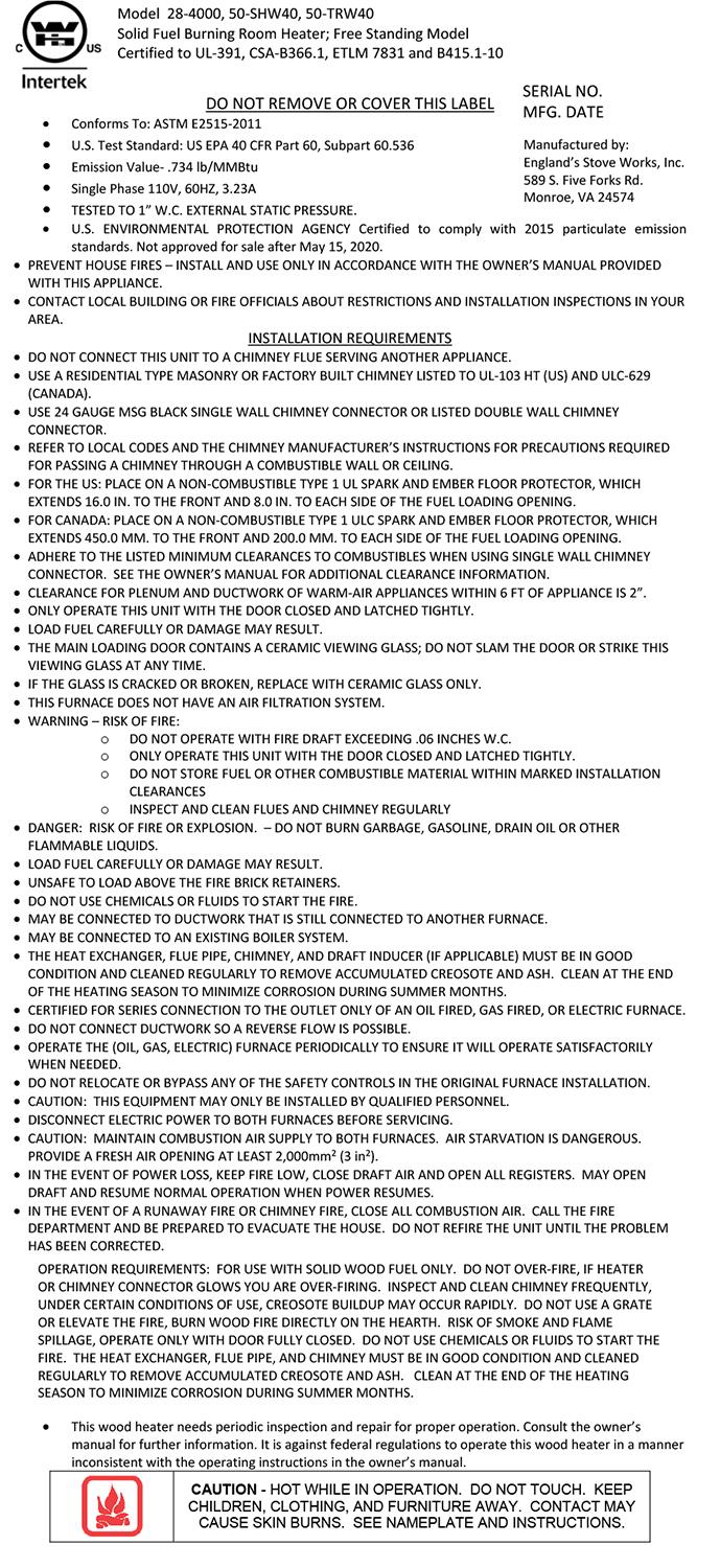
3 INSTALLATION AND OPERATION MANUAL MODELS: ; 50-SHW40; 50-TRW40 WOOD ADD-ON FURNACE Thank you for purchasing this product from a fine line of heating equipment. Please read this manual before attempting to move or install your unit. We wish you many years of safe heating pleasure with your new heating appliance. Visit our web site at for helpful information, frequently asked questions, parts & accessory orders and more. Please Note the Following Precautionary Statements: England s Stove Works highly recommends the use of smoke detectors and Carbon Monoxide detectors with any hearth product, including this unit. Follow all manufacturer s instructions when using smoke and Carbon Monoxide detectors. CAUTION: This unit must be installed in accordance with these instructions and must comply with local building and fire codes. Failure to do so could result in a chimney or house fire. Keep children, furniture, fixtures and all combustible materials away from any heating appliance. Maintain a minimum clearance of 18 inches (457.2 mm) from the flue pipe to any combustibles, or as recommended by the pipe manufacturer. Refer to information in this manual and on the unit, and to all pipe manufacturers instructions. This unit is not mobile home approved. Do not install this unit in a mobile home! READ THESE INSTRUCTIONS CAREFULLY BEFORE INSTALLING THIS MODEL. SAVE THESE INSTRUCTIONS FOR FUTURE REFERENCE. INSTALLATION SHOULD BE PERFORMED BY A QUALIFIED INSTALLER. NOTE: IF YOU HAVE A PROBLEM WITH THIS UNIT, DO NOT RETURN IT TO THE DEALER. PLEASE CONTACT TECHNICAL SUPPORT at (800) FUEL: WOOD HEATING CAPACITY: Approx. 3,000 SQ. FT (when fed into existing ductwork) TESTED TO: UL 391, CSA-B366.1, ETLM 78.1, B HEAT OUTPUT: 11,665-34,510 BTU/HR
4 Thank you for purchasing this fine product from England s Stove Works! England's Stove Works was started, and is still owned by, a family that believes strongly in a "Do It Yourself" spirit that s one reason you found this product at your favorite Do It Yourself store. We intentionally design and build our stoves so that any homeowner can maintain his or her unit with basic tools, and we're always more than happy to show you how to do the job as easily and as inexpensively as possible. From our free, downloadable service sheets to our "wizard-style," click-through Troubleshooting guide on our web site, we have always tried to help our customers stay "heat-ready," especially when oil and electricity prices continue to skyrocket. Please look at our vast Help section on our web site and call our Technical Support department at (800) if you need any help with your unit. We are nearly always able to help walk you through any repairs, problems or questions you may have. PLEASE NOTE: While information obtained on our web site and through our 800 number is always free of charge, there will be a service charge incurred with any on-site repairs or maintenance that we may arrange. Wishing you years of efficient, quality and comfy heating, England s Stove Works Technical Support Department CAUTION: Stove is heavy. In addition, when handling any sheet metal products, be aware that there may be sharp edges or burrs. Although we make every effort to eliminate any sharp edges, please use caution when handling any metal parts. Remember to disconnect (unplug) the stove from the power source and allow it to completely cool down before performing any maintenance. This manual is available for free download on the manufacturer s web site. It is a copyrighted document and resale is strictly prohibited. The manufacturer may update this manual occasionally and cannot be responsible for problems including injuries or damages resulting from the use of information found in any manual from unauthorized sources. PLEASE NOTE: If you purchased this model from certain stores, their model number may end in L LC H CT, etc. This manual does apply to those models as well. 4
5 INSTALLATION SAFETY NOTICE: IF THIS UNIT IS NOT PROPERLY INSTALLED, A HOUSE FIRE MAY RESULT. FOR YOUR SAFETY AND PROTECTION, FOLLOW ALL OF THE INSTALLATION INSTRUCTIONS. INSTALLATION SHOULD BE PERFORMED BY A QUALIFIED INSTALLER. CONTACT YOUR LOCAL BUILDING OR FIRE OFFICIALS FOR RESTRICTIONS AND INSTALLATION INSPECTIONS REQUIRED IN YOUR AREA. IMPORTANT: DO NOT OVER-FIRE. SEE DO NOT OVER-FIRE YOUR UNIT IN THE OPERATING INSTRUCTIONS SECTION. CAUTION Hot Surfaces: Keep children away. Do not touch during operation. FLUE SYSTEM Note: Flue systems and flue pipe are not furnished with the unit; they must be purchased separately. Follow all manufacturers instructions. THE UNIT IS NOT TO BE CONNECTED TO A CHIMNEY FLUE SERVING ANOTHER APPLIANCE. Inspect flue pipes, joints and seals regularly to ensure that smoke and flue gases are not drawing into, and circulated by the air-circulation system. Cleaning of the heat exchanger, flue pipe, chimney and draft inducer if used, is especially important at the end of the summer heating season to minimize corrosion during the summer months caused by accumulated ash. This appliance requires a masonry or pre-manufactured chimney listed to UL103HT, sized correctly. Existing Flue System The Add-On furnace is designed to connect to an existing flue system, such as masonry or HT Pipe premanufactured flue pipe. If you have a masonry flue system, you need to inspect the inner liner very carefully for cracks. If there is no liner in your chimney, we recommend you install a stainless steel liner, or have one installed. If you have an existing premanufactured flue system, it should be inspected to ensure there are no cracks, buckling or warping. We strongly recommend that you have a qualified chimney sweep clean and inspect your flue system. DO NOT CONNECT THIS UNIT TO A CHIMNEY FLUE SERVING ANOTHER APPLIANCE. Always try to position the unit as close as possible to the flue servicing the unit. The fewer total pipes that are installed, the better the stove will draw. Flue Size Required The proper flue size is determined by the inside diameter of the flue collar on the unit. This furnace is equipped with a 6 inch (152.4 mm) TOP EXHAUST flue collar. The connector pipe should be six inches or larger, but never less in diameter than the collar on the stove. The area of the chimney liner must be equal to or greater than the area of the collar on the stove. Example: The area of a 6 inch (152.4 mm) diameter flue collar is square inches ( sq. cm); therefore, the connector pipe should be at least a 6 inch (152.4 mm) diameter pipe and the chimney liner must be at least square inches ( sq. cm) but no greater than 84.8 square inches ( sq. cm). 5
6 Connector pipe should be (at minimum) 24-gauge steel and 18 inches (457.2 mm) from a combustible wall or ceiling. This unit is tested with single-wall pipe only. IMPORTANT: Be sure to refer to the data label and other markings on the appliance for additional information, including clearances to combustibles. Installation of a New Flue System Masonry Flue: If you are considering a masonry flue (see Figure 1), you should contact your local building officials for the proper procedures required in the construction. We recommend that you consult with and have your flue built by a licensed, bonded contractor. Most masonry flues are placed against the outside wall and extend up the side of the house. A flue thimble is then inserted through the wall making the connection with the vertical flue and the stove flue pipe. Extreme caution should be exercised when drilling through the wall. You must maintain proper clearances between the connecting liner and any combustible wall. We do recommend that you have a flue clean out door at least 2 (two feet; cm) below the flue thimble for easy access and cleaning. This door should be made as air tight as possible. It is the customer s responsibility to be sure the chimney (or flue system) is in a safe operating condition. The manufacturer will not be held responsible for an accident attributed to a unit connected to a faulty chimney or flue system. Premanufactured Flue System: In the past few years, premanufactured flue systems have become very popular. This type system is fairly easy to install and when installed correctly, it is a very safe. There are many premanufactured flue systems on the market from which to choose. In making your choice, be sure the system has a recognized label of approval such as U.L., B.O.C.A. or I.C.B.O. Any of these labels will ensure the flue system is constructed of the proper materials and meets the required safety standards. Your local dealer will normally handle an approved, high-quality flue system. NOTE: Be sure to use HT Pipe. There are two very popular methods of installing a premanufactured flue system. The first, which is the least expensive, is up through the ceiling and out the roof (see Figure 2). This is the most direct route and creates more draft because less pipe is normally used. Single wall pipe (24 gauge) is used up to the ceiling, with triple walled pipe through the attic and out the roof. The second method of installation is to go through the wall and up the outside of your home or structure (see Figure 2). This method is more expensive because it requires more pipe, and once outside the home insulated or triple wall pipe is required. Extreme care should be used in any installation, and the manufacturers instructions should always be followed. If you choose this type installation, a qualified contractor or bonded chimney sweep should install this system. It is the customers responsibility to be sure the flue system is in a safe operating condition. *IMPROPER INSTALLATION: The manufacturer will not be held responsible for damage caused by the malfunction of a stove due to improper venting or installation. Call and/or consult a professional installer if you have any questions. 6
7 WHY THE CORRECT FLUE SIZE IS IMPORTANT: 6 Draft is the force that moves air from the appliance up through the chimney. The amount of draft in your chimney depends on the length of the chimney, local geography, nearby obstructions, and other factors. Too much draft may cause excessive temperatures in the appliance. An uncontrolled burn or a glowing red part or chimney connector can indicate excessive draft. Inadequate draft may cause back puffing into the room and plugging of the chimney and/or cause the appliance to leak smoke into the room through appliance and chimney connector joints. Today s solid fuel appliances are much more efficient than in the past. The units are designed to give you controlled combustion, as well as maximum heat transfer, using less fuel to do so. The design of your new appliance is such that the exhaust smoke is now at lower temperatures than in the past, therefore requiring proper chimney size to give adequate draft. If your chimney is too large, the heater will have a difficult time raising the temperature of the flue enough to provide adequate draft, which can cause a "smoke back," poor burn, or both. Should you experience such problems, call in a local chimney expert. With the door closed, the rate of burning is regulated by the amount of air allowed to enter the unit through the air control. With experience, you will be able to set the control for heat and burning time desired. Attempts to achieve higher output rates that exceed heater design specifications can result in permanent damage to the heater. The recommended wood load is level with the top of the firebricks. Overloading may prevent sufficient air entering the heater to properly fuel the fire. DO NOT tamper with the combustion air control beyond the normal adjustment capacity. Operate this heater only with the door closed. DO NOT OVERFIRE. If the heater or chimney connector glows, you are overfiring. In the event of power loss, keep the fire low, close draft air and open all registers. ALWAYS PROVIDE A SOURCE OF FRESH AIR INTO THE ROOM WHERE THE UNIT IS INSTALLED. FAILURE TO DO SO MAY RESULT IN AIR STARVATION OF OTHER FUEL BURNING APPLIANCES AND THE POSSIBLE DEVELOPMENT OF HAZARDOUS CONDITIONS. THIS HEATER IS EXTREMELY HOT WHILE IN OPERATION. SERIOUS BURNS CAN RESULT FROM CONTACT. CAUTION SHOULD BE OBSERVED, ESPECIALLY WHEN CHILDREN ARE PRESENT. 7
8 INSTALLATION Venting Introduction Venting Guidelines This wood stove operates on a natural draft system, in which the chimney system pulls air through the stove. This unit must be installed in accordance with the following detailed descriptions of venting techniques; not installing the stove in accordance with the details listed here can result in poor stove performance, property damage, bodily injury or death. Avoid make shift compromises when installing the venting system. England s Stove Works is not responsible for any damage incurred due to a poor or unsafe installation. Be certain that all aspects of the venting system are installed to the venting manufacturer s instructions, particularly the required clearances to combustibles. Also, be certain to use an attic radiation shield to prevent insulation from contacting a chimney which passes through an attic. The chimney system is the engine which drives a wood stove, so it is imperative for proper unit function that the venting system be installed exactly as described in the following section. If questions arise pertaining to the safe installation of the stove, our Technical Support line ( ) is available. Contact your local code official to be certain your installation meets local and national fire codes, and if you re uncertain about how to safely install the stove, we strongly recommend contacting a local NFI certified installer to perform the installation. WARNING: Venting system surfaces get HOT, and can cause burns if touched. Noncombustible shielding or guards may be required WARNING: If Fans are installed in the storage area, they should not create negative pressures in the room where the solid fuel-burning appliance is located ALWAYS install vent pipe in strict adherence to the instructions and clearances included with your venting system. DO NOT connect this wood stove to a chimney flue which also serves another appliance. DO NOT install a flue pipe damper or any other restrictive device in the exhaust venting system of this unit. USE an approved wall thimble when passing through a wall and a ceiling support/fire stop when passing through a ceiling. INSTALL three sheet metal screws at every chimney connector joint. AVOID excessive horizontal runs and elbows, as both will reduce the draft of the venting system and will result in poor stove performance. INSPECT your venting system often, to be certain it is clear of creosote, fly ash and other restrictions. CLEAN the venting system as detailed in the maintenance section of this manual. ADHERE to the rule regarding chimney terminations. INSTALL single wall chimney connector with the male end down to prevent creosote leakage. Follow double wall chimney connector manufacturer s instructions regarding proper pipe installation. The Rule: The chimney system must terminate 3.0 ft above the point where it s centerline passes through the roof AND the chimney must terminate 2.0 ft. above part of the dwelling within a 10 ft. radius of the chimney. 8
9 Installation Diagrams and Thermostat Wiring This appliance requires a masonry or pre-manufactured chimney listed to UL103HT, sized correctly. 18 Min. 18 Min. 18 Min Figure 2 Installation into a HT Pipe Flue System LEFT Through the Roof RIGHT Through the Wall IMPORTANT NOTE: Do NOT connect this furnace to an external thermostat. Figure 1 Installation into a Masonry Flue NOTE: See notes on OUTSIDE AIR, page 11. See FLOOR AND WALL PROTECTION sections and data label on stove for all clearances. Recommended position of Backflow Damper Air Flow Figure 3 Hot air outlet hook-up to ductwork NOTE: Be sure to connect to ductwork from furnace s 8 hot air outlet only (see manual). To prevent air flow from central furnace being directed back into the Add-on furnace: A Backflow Damper is required in the 8 hot air outlet pipe that connects from the Add-On Furnace to the Central Furnace (see Figure 3). We also recommend a eight inch (203.2 mm), 90 degree elbow (a slightly larger hole will be required for installation) inside the central 9 furnace plenum or ductwork. Figure 4 Blower thermostat wiring diagram
10 FLOOR AND WALL PROTECTION Floor Protection There is no protection required if your floor is constructed of a noncombustible material such as concrete. If your floor is constructed of a combustible material such as hardwood, carpet or linoleum some type of floor protection will be required. When selecting the required floor protection it is important that you install a U.L. approved board. The approved floor protection should be placed underneath the furnace, and should be large enough to provide a minimum of 8 inches (203.2 mm) behind the unit, 8 inches (203.2 mm) on both sides, and 16 inches (406.4 mm) at the front door location. It should also be placed underneath the chimney connector and extend at least 2 inches (50.8 mm) on either side of the chimney connector (CANADA: Place on a non-combustible Type 1 ULC Spark & Ember floor protector, which extends mm to the front and mm to the rear, and each side of the fuel loading opening). Wall Protection Your furnace can be placed as close as 8 inches (203.2 mm) from a combustible wall (such as paneling, wallpaper or drywall) to the side of the unit; from the back of the unit, 10 inches (254 mm) is required to a combustible. The single-wall pipe would need to remain at least 14 inches (355.6 mm) from combustible surfaces at the back wall, and 21.5 inches (546.1 mm) from combustible surfaces at the side walls. NOTE: Always check and follow pipe manufacturer s instructions, and all local codes. In corner installations, the unit should be placed so that the stove is at least 12 inches (304.8 mm) from any combustibles, and the single-wall pipe should be at least 23 inches (584.2 mm) from any combustibles in a corner installation. Wall protection will be required if you need to place you furnace closer than the allowed measurements stated above, and this can be accomplished by adding a protective board to the wall. The board can be mounted to the wall leaving a 1-inch (25.4 mm) air space between the wall and the board. This can be done by using metal spacers, and should allow you to place your unit so that the sides of the unit are at least 12 inches (304.8 mm) from the protective board be sure to check and follow the board manufacturer s instructions and any local codes. FREESTANDING PLACEMENT AND HOOK-UP Once you have completed your flue system and installed the floor protection, you are now ready to place the unit. All of our stoves are well constructed, making them very heavy. We recommend using a handcart for moving the unit; the door and firebrick can be removed to make the unit slightly lighter (first make a diagram of the firebrick layout for later reference). Never attempt to handle this product alone. After the unit is in place the flue collar, spring handles and any optional equipment can be added. Page 10
11 Outside Air Connection It is recommended, especially in air-tight homes, to supply the combustion air into the unit from outside the dwelling. This can be done by running a thin gauge 3-inch (76.2 mm) pipe (flex or rigid) from the air inlet pipe located on the rear of the stove through the floor or wall (measure pipe to ensure you obtain the correct size). The outside end of this pipe should be covered in some manner (i.e. screen) to keep it clear of foreign matter. Be sure to keep it above the snowdrift line and clear of leaves and other debris. If you are installing this stove in a regular dwelling this connection is not necessary, but is recommended in air-tight homes. With ANY installation, it will be necessary to have at least some length of pipe connected to the air inlet. It should be long enough to reach past the blower that is on the rear of the furnace, or the blower will interfere with the furnace s intake air and make it difficult, if not impossible, to maintain a fire. A kit is available from England s Stove Works, Inc. designed for connecting this unit to outside combustion air. [Part No. AC-OAK3] Outside combustion may be necessary if: 1. The furnace does not draw steadily, smell, experiences smoke roll-out, burns poorly, or back drafts whether or not there is combustion present. 2. Any of the above symptoms are alleviated by opening a window slightly on a calm day. 3. The house is equipped with a well-sealed vapor barrier and tight fitting windows and/or has any powered devices which exhaust house air. 4. There is excessive condensation on windows in the winter. 5. A ventilation system is installed in the house. Chimney Connector Pipe This black pipe must be 6 inches (152.4 mm) in diameter and a 24-gauge or heavier pipe. Do not use aluminum or galvanized steel, as they cannot withstand the high temperatures of a wood fire. Do not use single wall pipe as a chimney. You must connect your stove to a chimney comparable to those illustrated in this manual. The chimney connector pipe lengths must be attached to the stove, and to each other, with the crimped end toward the stove. This will allow any creosote that might form to remain within the pipe. As a safety precaution, all joints should be sealed with high temperature silicone (AC-RTV3) and secured with three sheet metal screws. For proper operation, the chimney connector should be kept as short as possible. Horizontal lengths of chimney connector pipe should never exceed 6 (6 feet; 1.82 m) and should have an upward slope of ¼ (one-quarter inch; 6.35 mm) per foot (304.8 mm). Maintain at least 18 inches (457.2 mm) clearance between the wall and ceiling on any chimney connector pipe unless wall protection is installed (consult pipe manufacturer s instructions and local codes). If using wall protection, the wall protection should be a U.L.-listed stove board with a one inch (25.4 mm) clearance (air space) between the board and the wall. This should reduce the clearance to a combustible to 12 inches (304.8 mm) again, be sure to check manufacturer s instructions and local codes. Page 11
12 THE FUNCTION OF THE ADD-ON FURNACE The Add-On Furnace is designed to be a supplemental hot air heating system that will connect to your existing heating system. The furnace will operate independently of your existing system, while using the same hot air ducts that your present furnace uses. The furnace comes standard with a 850 cfm (part number BM-1376) blower that pushes hot air up both sides and across the top of the unit through an inner-duct chamber built around the firebox. The heated air exits the unit through an 8-inch (203.2 mm) outlet located on the top, near the front of the furnace. The 8-inch (203.2 mm) pipe connected at this exit will route the heated air into your duct system. A wood furnace does not recover as fast as a conventional furnace, so the unit is equipped with a thermostat (part number AC-1339, see Figure 4) to turn the blower on and off. This ensures that the blower will always be moving hot air into your duct system. It is important that you maintain a continuous fire for maximum performance. The furnace has a firebrick system that is designed to last for years. Replacing one or two firebricks as necessary is fairly inexpensive, and the brick will hold more heat and make your wood last longer as it burns. HOT AIR HOOK-UP (See Fig. 3) NOTE: The warm air supply-duct system should be constructed of materials with a minimum temperature rating of 250 deg. F. Also, the plenums installed to the furnaces are to be constructed of metal. NOTE: The hot air supply outlet of this supplementary furnace should not be connected to the cold-air return inlet of the central furnace, since a possibility exists that components of the central furnace could overheat in this situation and cause the central furnace to operate other than as intended. Before making the hot air hook-up, you should have your unit positioned as close to the flue connector as possible and have your flue pipe installed. If this has not been done, please do so before continuing. Located on the top, near the front of the unit is an 8-inch (203.2 mm) opening for the mounting of the flue collar. When mounting this part, be absolutely sure it is fastened securely to the opening, as this will be the hot air exit. Thirty gauge or thicker pipe should be used from here to the hot air trunk line of your existing hot air system. Using the least possible amount of pipe will help the heat transfer to your duct system. Cut an 8-inch (203.2 mm) diameter hole in the main trunk line of the furnace duct, which is usually located on the top of the central furnace. Place the 8 inch (203.2 mm) pipe from the wood furnace into the hole (see Figure 3) and seal the connection with duct tape. Thirty gauge or thicker galvanized pipe should be used to connect to the existing furnace duct. Sheet metal screws should be used to secure each joint of pipe, and an aluminum heat resistant tape can be wrapped around each joint to give an airtight seal. See Figure 3 for more information, including the use of a Backflow Damper and 90-degree elbow. Follow the manufacturer s instructions when installing a Backflow Damper. Page 12


13 BLOWER AND THERMOSTAT INSTALLATION Blower Installation The BM-1376 blower will be mounted to the opening that is located at the bottom on the rear of the stove. The blower will simply mount to the opening with the five screws that are installed on the unit. NOTE: The heat circulation blower on this furnace requires periodic lubrication; this lubrication should be performed no less than every three months of normal operation. To properly lubricate the blower, use an eye dropper or similar dispensing device to drip 5-7 droplets of SAE 20 oil into the oil port on the side of the blower motor. Thermostat Installation The thermostat, blower and power cord are all prewired (see Figure 4 for thermostat instructions); however, the thermostat must be connected to the furnace after installation of the blower. Do this by inserting the probe portion into the stove (remove the cover first, to reveal the mounting plate) and fastening the thermostat to the unit with the four screws that are mounted on the furnace. Probe thermostat mounts in top rear (4 screws) Outside Air will connect beside blower OPERATING INSTRUCTIONS Blower mounts on bottom rear (5 screws) Page 13
14 OPERATION Building a Fire Following these guidelines will help ensure a proper fire, as well as helping minimize visible emissions. WARNING: Do not operate unit with bottom (ash) pan open. Operating unit with ash pan open can cause over-firing and damage the unit, and will void any warranty. Except as specified in Operating Instructions, do not operate unit with main door open. BURN WOOD ONLY! CAUTION: Do not use a grate or elevate the fire. Build the wood fire directly on the bricks. When the stove is used for the first time, solvents in the paint will smoke off as the stove cures. Notice: The surface of your new furnace and the connector pipe may initially smoke for a short time, this is no cause for alarm. This is called cooking out, and it is advisable to open doors and windows in your dwelling during the first two hours (approximately) of operation. WOOD This heater is designed to burn natural wood only. Higher efficiency and lower emissions generally result when burning air-dried seasoned hardwood, as compared to softwood or to green or freshly-cut hardwood. Use only dry, seasoned wood. Green wood, besides burning at only 60 percent of the fuel value of dry wood, deposits creosote on the inside of the stove and along the chimney. This can cause extreme danger of chimney fire. To be called seasoned, wood must be dried for a year. Regardless of whether the wood is green or seasoned, it should be stored in a ventilated, sheltered area to allow proper drying during the year. Wood should be stored beyond recommended clearances from combustibles. Establish a routine for the storage of fuel, care of the appliance, and firing techniques. Check daily for creosote build up until experience shows how often cleaning is necessary. Be aware that the hotter the fire, the less creosote is deposited, and that weekly cleaning may be needed in mild weather, even though monthly cleaning may be enough in the coldest months. A small intense fire is preferable to a large smoldering fire to reduce the amount of creosote deposition. Have a clearly understood plan to handle a chimney fire. DO NOT BURN: Treated Wood, Garbage, Solvents, Trash, Cardboard, Colored Paper or Coal. FIRST FIRE Remember to ventilate well. Allow the stove to cure before burning for long periods of time at high temperatures. Page 14
15 Flat spots on the painted surface are normal. Shiny spots on the painted surface (before burning) are normal. Call Technical Support at (800) if you have any questions. BUILDING A FIRE 1. Open the air inlet control fully (NOTE: The control is located under the ash drawer. Pulling out on the control opens it). 2. Place a small amount of crumpled paper in the stove. 3. Cover the paper with a generous amount of kindling in a teepee shape, and a few small pieces of wood. 4. Ignite this fuel and close the door most of the way (leave it open slightly). 5. Add larger pieces of wood as the fire progresses, being careful not to overload. Do not fill the firebox beyond the firebrick area. A coal bed of (ideally) 1 to 2 (25.4 to 50.8 mm) should be established to achieve optimum performance. 6. This unit is designed to function most effectively when air is allowed to circulate to all areas of the firebox. A good way of achieving this is to rake a small (1 to 2 or 25.4 to 50.8 mm wide) trough in the center of the coal bed, from front to back, prior to loading the fuel. 7. Once fuel has been loaded, close the door and fully open the air inlet control, until the fire is well established (approximately 20 minutes), being careful not to over-fire. 8. Readjust the air inlet control to the desired burn rate. If excessive smoke fills the firebox, open the air inlet control slightly, until flames resume and the wood is sufficiently ignited. Basically, Closed = Low; ½ Way Open = Medium; and Fully Open = High. 9. When refueling, adjust the air control to the fully open position. When the fire brightens, open the door VERY slowly and carefully. This will prevent gases from igniting and causing smoke and flame spillage. 10. At this point you may add fuel, being careful not to overload. Establish a routine for the storage of fuel, care of the appliance, and firing techniques. Check daily for creosote build up until experience shows how often cleaning is necessary. Be aware that the hotter the fire, the less creosote is deposited, and that weekly cleaning may be needed in mild weather, even though monthly cleaning may be enough in the coldest months. A small intense fire is preferable to a large smoldering fire to reduce the amount of creosote deposition. Have a clearly understood plan to handle a chimney fire. Page 15
16 DANGER- RISK OF FIRE OR EXPLOSION CAUTION NEVER USE GASOLINE, GASOLINE-TYPE LANTERN FUEL, KEROSENE, CHARCOAL LIGHTER FLUID, OR SIMILAR LIQUIDS TO START OR FRESHEN UP A FIRE IN THIS HEATER. KEEP ALL SUCH LIQUIDS WELL AWAY FROM THE HEATER WHILE IN USE. ADDITIONALLY, NEVER APPLY FIRE-STARTER TO ANY HOT SURFACE OR EMBERS IN THE STOVE. DO NOT USE CHEMICALS OR FLUIDS TO START THE FIRE. DO NOT BURN FLAMMABLE FLUIDS SUCH AS GASOLINE, NAPHTHA OR ENGINE OIL. DO NOT BURN GARBAGE; LAWN CLIPPINGS OR YARD WASTE; MATERIALS CONTAINING RUBBER, INCLUDING TIRES; MATERIALS CONTAINING PLASTIC; WASTE PETROLEUM PRODUCTS, PAINT OR PAINT THINNERS, OR ASPHALT PRODUCTS; MATERIALS CONTAINING ASBESTOS; CONSTRUCTION OR DEMOLITION DEBRIS; RAILROAD TIES OR PRESSURE-TREATED WOOD; MANURE OR ANIMAL REMAINS; PAPER PRODUCTS, CARDBOARD, PLYWOOD OR PARTICLEBOARD. THE PROHIBITION AGAINST BURNING THESE MATERIALS DOES NOT PROHIBIT THE USE OF FIRESTARTERS MADE FROM PAPER, CARDBOARD, SAWDUST, WAX AND SIMILAR SUBSTANCES FOR THE PURPOSE OF STARTING A FIRE IN AN AFFECTED WOOD HEATER. BURNING THESE MATERIALS MAY RESULT IN RELEASE OF TOXIC FUMES OR RENDER THE HEATER INEFFECTIVE AND CAUSE SMOKE. WARNING RISK OF FIRE Do not operate with flue draft exceeding.05 in. water column. Do not operate with fuel loading or ash removal doors open. Do not store fuel or other combustible material within marked installation clearances, or anywhere near unit. Inspect and clean flues and chimney regularly. Practical Tips for Building a Fire Once your wood-burning appliance is properly installed, building an effective fire requires good firewood (using the right wood in the right amount) and good fire building practices. The following practical steps will help you obtain the best efficiency from your wood stove or fireplace. Season wood outdoors through the summer for at least 6 months before burning it. Properly seasoned wood is darker, has cracks in the end grain, and sounds hollow when smacked against another piece of wood. Store wood outdoors, stacked neatly off the ground with the top covered. Burn only dry, well-seasoned wood that has been split properly. Start fires with newspaper and dry kindling as discussed earlier in the manual. Burn hot fires. Page 16
17 To maintain proper airflow, regularly remove ashes from your wood-burning appliance into a metal container with a cover and store outdoors. Safe Wood-burning Practices Once your wood-burning appliance is properly installed, follow these guidelines for safe operation: Keep all flammable household items drapes, furniture, newspapers, and books far away from the appliance. Start fires only with newspaper, dry kindling and all natural or organic fire starters. Never start a fire with gasoline, kerosene, or charcoal starter. Do not burn wet or green (unseasoned) logs. Do not use logs made from wax and sawdust in your wood stove they are made for open hearth fireplaces. If you use manufactured logs, choose those made from 100 percent compressed sawdust. Build hot fires. For most appliances, a smoldering fire is not a safe or efficient fire. Keep the doors of your wood-burning appliance closed unless loading or stoking the live fire. Harmful chemicals, like carbon monoxide, can be released into your home. Regularly remove ashes from your wood-burning appliance into a metal container with a cover. Store the container of ashes outdoors on a cement or brick slab (not on a wood deck or near wood). Keep a fire extinguisher handy. Remember to check your local air quality forecast before you burn. Draft Control and Draft This unit has a draft control system that is used to determine the amount of combustion air that enters the stove. The more the damper is opened, the more air will enter the firebox and thereby increase the heat output of the unit. This will, by creating a hotter fire, make your fuel burn faster. CONTROL SETTINGS for Air Inlet Control Burn Rate Low Med. Low Med. High High Inlet Air Setting Fully Closed ¼ Open ¾ Open Fully Open WARNING: Do not alter the air inlet control for any reason. No two flue systems are identical; you will have to experiment with your furnace draft settings to achieve the maximum burn time and heat output. If you have any problem regulating the furnace, consult your local dealer or our Technical Support department at (800) Page 17
18 Draft: Draft is the force which moves air from the appliance up through the chimney. The amount of draft in your chimney depends on the length of the chimney, local geography, nearby obstructions and other factors. Too much draft may cause excessive temperatures in the appliance and may damage the fiber boards and burner tubes. Inadequate draft may cause backpuffing into the room and plugging of the chimney. Inadequate draft will cause the appliance to leak smoke into the room through appliance and chimney connector joints. An uncontrollable burn or excessive temperature indicates excessive draft. Please be mindful of installation location: Inversion and other air quality issues can arise in valleys or if unit is installed close to neighboring homes. Measuring Draft: Using a manometer with an appropriate scale range, connect the testing tube to the chimney connector. End of testing tube should be inserted in chimney connector approximately 12 (305mm) above the elbow/t attached to the furnace flue and so that approximately 1 (25 mm) of tube extends into the exhaust system. Any hole made in the chimney connector for insertion of manometer tube shall be adequately sealed with high temp sealant materials when testing is complete. Chimney draft should be a minimum of W.C. (-10 Pa) to a maximum of W.C. (-15 Pa). Do Not Over-Fire Your Unit IMPORTANT: Using flammable liquids, too much wood, or burning trash in this unit may result in over-firing. If the chimney connector pipe glows red or even worse white, the stove is over-fired. This condition could ignite creosote in the chimney, which in turn could cause a house fire. CAUTION: If you do over-fire the unit, immediately close the draft control and the door if it is open. You should get out of the house and call the fire department. Do not use the stove again until the chimney and connector pipe have been inspected and any damaged parts replaced. A chimney sweep can perform the inspection and make any necessary repairs. Everyday Fueling This furnace is designed to burn six to eight hours on one filling of good seasoned wood. To refuel the unit, proceed as follows: 1. Open the draft control as described previously. Crack the door approximately 1-inch (25.4 mm) and leave it in this manner for two to five minutes. This will allow the excess smoke to go up the chimney system by increasing the draft. 2. Now you can slowly open the door; you should see a hot bed of coals in the firebox. If the fire has burned out, stop here and refer to the procedure for Building a Fire. Page 18
19 3. Load the firebox with dry seasoned wood. Do NOT load any higher than the side brick retainers. Leave the door cracked approximately 1/2 (one-half inch; 12.7 mm). Allow the fire to burn in this manner for 15 to 20 minutes. 4. Close the door completely, and leave the draft control in the open position, and allow the furnace to burn in this manner for another 5 to 10 minutes. 5. Open the draft control to your desired setting as described previously in Building a Fire. Moisture Meter Firewood is ready at 10-25% moisture content. Newly-cut logs can have a moisture content (MC) of 80% or more, depending on species. Since wood shrinks, and can also split, twist or otherwise change shape as it dries, most wood is dried before being used. Air drying, or seasoning, is the most common method used for cord wood. In most parts of the United States, the minimum moisture content that can be generally obtained in air drying is about 12 to 15 percent. Most air-dried material is usually closer to 20 percent moisture content when used. To test your firewood, simply push the pins into the wood and wait for a reading. Remember, don't just stick the meter into the ends of your firewood. To get the most accurate reading, split the wood and test the center. The center of the log will contain the most moisture. How Far Should I Drive Non-Insulated Pins into Wood? To full depth if possible. However, at moisture levels below 10%, it is usually sufficient to make good, positive contact with the wood. At higher levels of moisture and especially if you have a steep gradient, full penetration is a must. Ash Removal and Disposal Regularly inspect the ash build-up in your unit and remove as necessary. Ashes can be removed from the unit by shoveling them off the firebrick. This unit has an ash drawer plate that can be removed from the stove; once removed, the ashes can be raked through the opening and into the ash pan. Caution: The ash drawer plate can be extremely hot!! Use heavy gloves to protect your hands. Lift and slide out the ash pan. Never remove red-hot ashes from the appliance; allow ashes to cool before dropping into the ash pan. After emptying the ashes, the ash pan can be placed back into the unit. Never leave the ash pan area open, or the unit unattended. Page 19
20 Disposal of Ashes Ashes should be placed in a metal container with a tight fitting lid. The closed container of ashes should be placed on a noncombustible floor or on the ground, well away from all combustible materials, pending final disposal. If the ashes are disposed of by burial in soil or otherwise locally dispersed, they should be retained in the closed container until all cinders have thoroughly cooled. Creosote Creosote Formation and Need for Removal When wood is burned slowly, it produces tar and other organic vapors, which combine with expelled moisture to form creosote. The creosote vapors condense in the relatively cool chimney flue of a slow-burning fire. As a result, creosote residue accumulates on the flue lining. When ignited, this creosote makes an extremely hot fire. The chimney connector and chimney should be inspected at least twice monthly during the heating season to determine if a creosote buildup has occurred. If creosote has accumulated it should be removed to reduce the risk of a chimney fire. Please visit our web site, and visit your stove model s information page for a link to video instructions including proper operation and best practices. CAUTION This unit is meant to operate only with door closed. Smoke spillage and an inefficient, lazy burn will result from attempting to operate the stove with the door open. Additionally, using prohibited fuels can create an unsafe situation and can also generate excess carbon monoxide. Carbon monoxide is an odorless, colorless gas which can be deadly. The use of a carbon monoxide detector is strongly recommended. Page 20
21 CARE AND MAINTENANCE (Unit must be cool and power unplugged before performing any maintenance) GLASS CARE The following use and safety tips should be observed: 1. Inspect the glass regularly for cracks or breaks. If you detect a crack or a break, extinguish the fire immediately, and contact your dealer or Technical Support at (800) for replacement (or log on to ). 2. Do not slam the door or otherwise impact the glass. When closing door, make sure that logs or other objects do not protrude and impact the glass. 3. Do not clean the glass with materials which may scratch (or otherwise damage) the glass. Scratches on the glass can develop into cracks or breaks. 4. Never attempt to clean the glass while the unit is hot. If the deposit is not very heavy, normal glass cleaners are adequate with a plain, non-abrasive scouring pad. Heavier deposits may be removed with the use of an oven cleaner. 5. NEVER put substances that can ignite explosively inside the unit, since even small explosions in confined areas can blow out the glass. 6. This unit has an airwash system, designed to reduce deposits on the glass. GASKET REPLACEMENT After extensive use, the sealing material which provides glass and door seal may need to be replaced if it does not sustain its resilience. Inspect the glass and door seal periodically to ensure proper seal. If the gaskets become frayed or worn, replace immediately. The following steps should be followed for replacement of the glass gasket: 1. Ensure that the appliance is not in operation, and is thoroughly cooled. 2. Remove the screws and glass holders. 3. Lift glass out. 4. Remove the old gasket, and clean the glass. 5. Replace the new gasket, starting at the bottom of the glass and working along the edges. Be sure to center the gasket channel on the glass. Page 21 Refer to the list at the rear of this manual for part numbers. You may order parts by calling (800) or logging on to REPLACE GLASS ONLY WITH HIGH-TEMPERATURE ROBAX PYROCERAM OF THE PROPER SIZE AND THICKNESS.
22 6. Trim the gasket to length and butt the ends together. 7. Replace the glass and holders in the door. Tighten, being sure not to over-tighten the screws. The following steps should be followed for replacement of the door gasket: 1. Ensure the appliance is not in operation and is thoroughly cooled. 2. Remove the old door gasket and clean the gasket channel. 3. Using an approved high-temperature gasket cement, apply a thin coat in the bottom of the channel. 4. Starting at the hinge side of the door, work into the channel around the door unit, trim to length and butt the ends together. 5. Close the door and allow three to four hours for the cement to set before restarting any fire. FIREBRICK This furnace is equipped with high density, high temperature firebrick. Any brick that become chipped or cracked, especially on the sides of the firebox, need to be replaced as needed. FINISH This unit is coated with high-temperature paint that will retain its original look for several years. If the unit should get wet, rust spots may appear; these can easily be covered with this high-temperature spray paint (plain steel wool can be used to remove the rust spots before repainting). Please use only our approved proprietary paint (Part AC-MBSP), as other brands may not adhere to the surface of this furnace. BLOWER AND THERMOSTAT This furnace comes with a 850 CFM blower (Part BM-1376). Over a period of time the intake of the blower can become clogged with lint or dust, and it will require some cleaning. To do this, unplug the blower from the power source and remove the screws that hold the blower to the stove (be sure the stove is cool before doing so). Then unscrew the motor from the blower and remove it, along with the impeller. A vacuum cleaner can be used to remove the foreign material from the intake. Reverse this procedure to re-mount the blower to the furnace. The AC-1339 thermostat requires no maintenance. It activates the blower when the firebox temperature rises to 125 degrees Fahrenheit; it also deactivates the blower when the temperature drops to 95 degrees Fahrenheit. By shutting off at 95 degrees, it allows the furnace to recover as the heat is extracted from the unit and forced through the duct system. Page 22
23 We recommend that you leave the thermostat at the factory settings until the unit has been burned for at least 30 days. FIBER BOARD THIS WOOD HEATER UTILIZES RECENT TECHNOLOGY, WHICH INCLUDES CERAMIC FIBER BOARD THAT IS LOCATED IN THE FIREBOX, AND RESTS ON TOP OF FOUR STAINLESS STEEL TUBES. DO NOT REMOVE THIS CERAMIC FIBER BOARD!!! IT IS A NECESSARY COMPONENT OF THE FIREBOX. ALSO PLEASE NOTE: THE CERAMIC FIBER BOARD MAY BECOME LOOSE DURING INITIAL SHIPPING. BE SURE IT IS LYING FLAT, ON TOP OF THE STAINLESS STEEL TUBES, AND PUSHED ALL THE WAY TO THE BACK OF THE UNIT, WITH NO GAPS BETWEEN IT AND THE BACK WALL OF THE STOVE. MAINTENANCE: This unit is equipped with a ceramic Fiber Board ceiling baffle (two pieces). After extensive use, the board should be removed and cleaned. The following steps should be followed for cleaning or replacement: 1. Ensure the appliance is not in operation and is completely cooled down. 2. There is one screw in each stainless steel tube holder, located in the fire box ceiling. Remove the screws from the front and middle tube holders. 3. Shift each loose tube to the right, so that one end comes completely out of the socket. Drop the end down and pull it out by pulling it back to the left. 4. Drop the first board down and push the left corner to the top left. Bring the right corner down to the bottom right of your door opening, and pull the right side out first. Repeat for the second board piece. 5. Vacuum the boards off and blow the carbon out of the tubes, if there is any buildup. 6. Re-install the boards and tubes, reversing the same method they were removed. Page 23
24 Page 24 Placement of Stainless Steel Burner Tubes for all , 50-SHW40 & 50-TRW40 stove models
25 CHIMNEY AND FLUE PIPE MAINTENANCE Chimney Maintenance Cleaning your chimney is not a difficult task; however, we recommend a professional do this job. A professional chimney sweep can detect problems in your system that you might not recognize. Smoke Detectors England s Stove Works, Inc. highly recommends the use of smoke detectors in every room of the house. However, locating a smoke detector directly above this unit can result in nuisance alarms. Flue Pipe Maintenance If you are connecting your unit to a masonry or premanufactured chimney you should use 24-gauge or thicker pipe (the thicker the pipe that is used, the longer it will last). This pipe will require some maintenance, and it should be cleaned as needed. A chimney sweep can do this job and also evaluate when the pipe needs replacing. Note: It is a good practice to clean your flue system in the spring to eliminate any lingering odor through the summer months. THINGS THAT COULD CAUSE THE UNIT TO SMOKE It is very important that all pipe connections be made airtight. This can be done with stove cement (or high-temperature silicon) and sheet metal screws at each pipe joint. If the joints are not airtight, air can be drawn through these areas, affecting the efficiency and/or safety of the unit. Ideally, all combustion air will be drawn through the outside air hook-up. If there is a clean-out door on your chimney, this should also be sealed in some manner to make it airtight. Downdrafts: One cause for chimney downdrafts is air being deflected down the chimney by nearby objects such as the roof, trees or a nearby hill. Another cause is flue gas being chilled as it passes through the flue system. A typical example of this would be the flue system cooling down and the smoke not being able to exit the system, thereby building up in the chimney. The chimney will then back puff if there is wind blowing across the top of the flue system. This situation can normally be avoided if the furnace runs at a sustained temperature, thus not allowing the system to cool down. Meets the 2015 U.S. Environmental Protection Agency s crib wood emission limits for wood heaters sold after May 15, 2015 Page 25
26 EPA INFORMATION The following additions to your owner s manual will enable you to achieve optimal emissions performance from your stove. Important safety tips are also included. Proper Installation Please refer to the Installation section of your owner s manual and follow the guidelines listed therein for safety and for optimal emissions performance. Additional information: Venting Introduction: Draft: Draft is the force which moves air from the appliance up through the chimney. The amount of draft in your chimney depends on the length of the chimney, local geography, nearby obstructions and other factors. Too much draft may cause excessive temperatures in the appliance and may damage the catalytic combustor. Inadequate draft may cause backpuffing into the room and plugging of the chimney or the catalyst. Inadequate draft will cause the appliance to leak smoke into the room through appliance and chimney connector joints. An uncontrollable burn or excessive temperature indicates excessive draft. Please be mindful of installation location: Inversion and other air quality issues can arise in valleys or if unit is installed close to neighboring homes. This wood stove operates on a natural draft system, in which the chimney system pulls air through the stove. This unit must be installed in accordance with the following detailed descriptions of venting techniques; not installing the stove in accordance with the details listed here can result in poor stove performance, property damage, bodily injury or death. Avoid make shift compromises when installing the venting system. England s Stove Works is not responsible for any damage incurred due to a poor or unsafe installation. Be certain that all aspects of the venting system are installed to the venting manufacturer s instructions, particularly the required clearances to combustibles. Also, be certain to use an attic radiation shield to prevent insulation from contacting a chimney which passes through an attic. The chimney system is the engine which drives a wood stove, so it is imperative for proper unit function that the venting system be installed exactly as described in the following section. If questions arise pertaining to the safe installation of the stove, our Technical Support line ( ) is available. Contact your local code official to be certain your installation meets local and national fire codes, and if you re uncertain about how to safely install the stove, we strongly recommend contacting a local NFI certified installer to perform the installation. Venting Guidelines: ALWAYS install vent pipe in strict adherence to the instructions and clearances included with your venting system. DO NOT connect this wood stove to a chimney flue which also serves another appliance. DO NOT install a flue pipe damper or any other restrictive device in the exhaust venting system of this unit. Page 26
27 USE an approved wall thimble when passing through a wall and a ceiling support/fire stop when passing through a ceiling. INSTALL three sheet metal screws at every chimney connector joint. AVOID excessive horizontal runs and elbows, as both will reduce the draft of the venting system and will result in poor stove performance. INSPECT your venting system often, to be certain it is clear of creosote, fly ash and other restrictions. CLEAN the venting system as detailed in the maintenance section of this manual. ADHERE to the rule regarding chimney terminations. INSTALL single wall chimney connector with the male end down to prevent creosote leakage. Follow double wall chimney connector manufacturer s instructions regarding proper pipe installation. WARNING: Venting system surfaces get HOT, and can cause burns if touched. Noncombustible shielding or guards may be required The Rule: The chimney system must terminate 3.0 ft above the point where it s centerline passes through the roof AND the chimney must terminate 2.0 ft. above part of the dwelling within a 10 ft. radius of the chimney. Operation and Maintenance Please refer to the Operation (Operating Instructions) and Maintenance (including Ash Removal/Disposal) sections of your owner s manual and follow the guidelines listed therein for safety and for optimal emissions performance. Additional Information: Following the instructions in your owner s manual for Building a Fire will ensure a proper fire, as well as helping minimize visible emissions. More: Fuel loading and re loading: Practical Tips for Building a Fire See your owner s manual for information on loading (and re loading) your fuel, as well as for fire starting procedures (i.e. Building a Fire ). Top Down Fires: The US EPA recognizes the effectiveness of the top down approach for starting fires. A good tutorial for this approach may be found at steps.html. When building top down fires, be sure to follow the instructions found in your owner s manual and contact our Technical Support if you have any questions. Fuel Selection: Once your wood burning appliance is properly installed, building an effective fire requires good firewood (using the right wood in the right amount) and good fire building practices. The following practical steps will help you obtain the best efficiency from your wood stove or fireplace. Season wood outdoors through the summer for at least 6 months before burning it. Properly seasoned wood is darker, has cracks in the end grain, and sounds hollow when smacked against another piece of wood. Store wood outdoors, stacked neatly off the ground with the top covered. Burn only dry, well seasoned wood that has been split properly. Start fires with newspaper and dry kindling as discussed earlier in the manual. Page 27
28 Burn hot fires. To maintain proper airflow, regularly remove ashes from your wood burning appliance into a metal container with a cover and store outdoors. Moisture Meter Information Firewood is ready at 10 25% moisture content. Newly cut logs can have a moisture content (MC) of 80% or more, depending on species. Since wood shrinks, and can also split, twist or otherwise change shape as it dries, most wood is dried before being used. Air drying, or seasoning, is the most common method used for cord wood. In most parts of the United States, the minimum moisture content that can be generally obtained in air drying is about 12 to 15 percent. Most air dried material is usually closer to 20 percent moisture content when used. To test your firewood, simply push the pins into the wood and wait for a reading. Remember, don't just stick the meter into the ends of your firewood. To get the most accurate reading, split the wood and test the center. The center of the log will contain the most moisture. How Far Should I Drive Non Insulated Pins into Wood? To full depth if possible. However, at moisture levels below 10%, it is usually sufficient to make good, positive contact with the wood. At higher levels of moisture and especially if you have a steep gradient, full penetration is a must. Page 28
29 WHAT FUELS NOT TO USE: CAUTION NEVER USE GASOLINE, GASOLINE TYPE LANTERN FUEL, KEROSENE, CHARCOAL LIGHTER FLUID, OR SIMILAR LIQUIDS TO START OR FRESHEN UP A FIRE IN THIS HEATER. KEEP ALL SUCH LIQUIDS WELL AWAY FROM THE HEATER WHILE IN USE. ADDITIONALLY, NEVER APPLY FIRE STARTER TO ANY HOT SURFACE OR EMBERS IN THE STOVE. DO NOT USE CHEMICALS OR FLUIDS TO START THE FIRE. DO NOT BURN FLAMMABLE FLUIDS SUCH AS GASOLINE, NAPHTHA OR ENGINE OIL. DO NOT BURN GARBAGE; LAWN CLIPPINGS OR YARD WASTE; MATERIALS CONTAINING RUBBER, INCLUDING TIRES; MATERIALS CONTAINING PLASTIC; WASTE PETROLEUM PRODUCTS, PAINT OR PAINT THINNERS, OR ASPHALT PRODUCTS; MATERIALS CONTAINING ASBESTOS; CONSTRUCTION OR DEMOLITION DEBRIS; RAILROAD TIES OR PRESSURE TREATED WOOD; MANURE OR ANIMAL REMAINS; SALT WATER DRIFTWOOD OR OTHER PREVIOUSLY SALT WATER SATURATED MATERIALS; UNSEASONED WOOD; PAPER PRODUCTS, CARDBOARD, PLYWOOD OR PARTICLEBOARD. THE PROHIBITION AGAINST BURNING THESE MATERIALS DOES NOT PROHIBIT THE USE OF FIRESTARTERS MADE FROM PAPER, CARDBOARD, SAWDUST, WAX AND SIMILAR SUBSTANCES FOR THE PURPOSE OF STARTING A FIRE IN AN AFFECTED WOOD HEATER. BURNING THESE MATERIALS MAY RESULT IN RELEASE OF TOXIC FUMES OR RENDER THE HEATER INEFFECTIVE AND CAUSE SMOKE. Safe Wood burning Practices Once your wood burning appliance is properly installed, follow these guidelines for safe operation: Keep all flammable household items drapes, furniture, newspapers, and books far away from the appliance. Start fires only with newspaper, dry kindling and all natural or organic fire starters. Never start a fire with gasoline, kerosene, or charcoal starter. Do not burn wet or green (unseasoned) logs. Do not use logs made from wax and sawdust in your wood stove they are made for open hearth fireplaces. If you use manufactured logs, choose those made from 100 percent compressed sawdust. Build hot fires. For most appliances, a smoldering fire is not a safe or efficient fire. Keep the doors of your wood burning appliance closed unless loading or stoking the live fire. Harmful chemicals, like carbon monoxide, can be released into your home. Regularly remove ashes from your wood burning appliance into a metal container with a cover. Store the container of ashes outdoors on a cement or brick slab (not on a wood deck or near wood). See ash removal instructions in your owner s manual. Keep a fire extinguisher handy. Remember to check your local air quality forecast before you burn. Page 29
30 Air Controls: SEE YOUR OWNER S MANUAL for information on the Proper Use of Air Controls (in the Operation section). ASH REMOVAL Follow your Owner s manual s instructions regarding removal and disposal of ashes. REPLACEMENT of parts that are critical to emissions performance Follow your Owner s manual s instructions regarding replacement of gaskets and other parts that are critical to emissions performance. Remember: This wood heater needs periodic inspection and repair for proper operation. It is against federal regulations to operate this wood heater in a manner inconsistent with operating instructions in this manual. More: Burner Tubes To replace a tube, first be sure that you order the correct tube you need to replace. Then using a 5/16 socket or open end wrench, remove the screw located on the left side of the tube. Be sure to keep the screw. Push the tube to the right then remove the tube (pulling the tube back to the left after that side has been removed from the hole). To replace, reverse the above procedure make sure to install the tubes in the correct order. (Front to Back) Smoke Detectors England s Stove Works, Inc. highly recommends the use of smoke detectors in every room of the house. However, locating a smoke detector directly above this unit can result in nuisance alarms. CAUTION This unit is meant to operate only with door closed. Smoke spillage and an inefficient, lazy burn will result from attempting to operate the stove with the door open. Additionally, using prohibited fuels can create an unsafe situation and can also generate excess carbon monoxide. Carbon monoxide is an odorless, colorless gas which can be deadly. The use of a carbon monoxide detector is strongly recommended. Compliance: This non catalytic wood heater meets the 2015 U.S. Environmental Protection Agency s crib wood emission limits for wood heaters sold after May 15, Tamper Warning: This wood heater has a manufacturer set minimum low burn rate that must not be altered. It is against federal regulations to alter this setting or otherwise operate this wood heater in a manner inconsistent with operating instructions in this manual. Warranty: See your Owner s manual for a Warranty Registration instruction page, as well as instructions for warranty procedures. For parts, warranty replacement procedures may be found at our parts store site: Page 30
31 ADD-ON FURNACE PARTS / OPTIONS LIST 1. AC-G30 DOOR GLASS KIT WITH GASKET 2. AC-GGK DOOR GLASS GASKET KIT (gasket only, no glass) 3. AC-DGKNC DOOR GASKET KIT (High-Density fiberglass rope gasket) 4. AC-30BT1 FRONT BURNER TUBE 5. AC-30BT2 SECOND BURNER TUBE (from Front) 6. AC-30BT3 THIRD BURNER TUBE (from Front) 7. AC-30BT4 REAR BURNER TUBE 8. AC-30CFB CERAMIC FIBER BOARD (2) 9. AC-ADW01 ASH PAN 10. AC-1339 THERMOSTAT 11. AC-2835BA BLOWER ASSEMBLY (Blower, Thermostat & Cord) 12. BM CFM BLOWER (Blower motor only) 13. AC-2840SP SIDE PANELS (2) 14. AC-2840TP TOP PANEL 15. AC-2840BP BACK PANEL 16. AC-2840PED BOTTOM PANEL (Pedestal Base) Not Shown: AC-SB 9 X 4 X 1 ¼ FIREBRICK (see Brick Layout diagram) AC-SB2 4 X 2 X 1 ¼ FIREBRICK (see Brick Layout diagram) AC-SB2.5 4 X 2 ½ X 1 ¼ FIREBRICK (see Brick Layout diagram) AC-MBSP BLACK SPRAY PAINT AC-SHN LARGE SPRING HANDLE (NICKEL) AC-SH4N SMALL SPRING HANDLE (NICKEL) CA-21A 8 FLUE COLLAR AC-6DBK-AD FLUE COLLAR ADAPTER Technical Support Department service@englanderstoves.com P.O. Box 206 Parts Orders ONLY: ( ) Monroe, VA Tech. Questions/Problems: ( ) (Fax: ) All replacement parts can be ordered from our factory at (Parts Orders ONLY): , or from our web store: store.heatredefined.com. Page 31
32 Steel Riser All Unmarked Brick are # 1 BRICK LAYOUT 1 (Unmarked on diagram) 9 x 4 x 1.25 brick (Qty. 25) 3 4 x 2 ½ x 1.25 brick (Qty. 1) 2 4 x 2 x 1.25 brick (Qty. 1) 4 Metal plate (Ash Drawer Plate, Qty. 1) Page 32
33 Page 33
INSTALLATION AND OPERATION MANUAL MODELS: , 50-SHW35 & 50-TRW35 WOOD ADD-ON FURNACE
 INSTALLATION AND OPERATION MANUAL MODELS: 28-3500, 50-SHW35 & 50-TRW35 WOOD ADD-ON FURNACE Thank you for purchasing this product from a fine line of heating equipment. Please read this manual before attempting
INTRODUCTION TO HITZER STOVES INSTALLATION AND OPERATION
 INTRODUCTION TO HITZER STOVES INSTALLATION AND OPERATION Welcome to our proud team of HITZER heater owners. Your HITZER heater has the finest in Swiss craftsmanship and quality material to assure you that
Malm Fireplaces, Inc. 368 Yolanda Avenue, Santa Rosa, CA (707) Fax: (707)
 Fax: (707)") Malm Fireplaces, Inc. 368 Yolanda Avenue, Santa Rosa, CA 95404 (707) 523-7747 - Fax: (707) 571-8036 info@malmfireplaces.com Fire Drum 2 Tested to U/L Standards 1482 and 737 Assembly And Installation Instructions
Malm Fireplaces, Inc. 368 Yolanda Avenue, Santa Rosa, CA 95404 (707) 523-7747 - Fax: (707) 571-8036 info@malmfireplaces.com Fire Drum 2 Tested to U/L Standards 1482 and 737 Assembly And Installation Instructions
HOMEOWNER'S GUIDE FOR YOUR CONTEMPO FIREPLACE TABLE OF CONTENTS
 10031 Southern SE Albuquerque NM 87123 505.291.0500 fax 505.291.9317 HOMEOWNER'S GUIDE FOR YOUR CONTEMPO FIREPLACE Before building your first fire, read this warranty and operation manual carefully. By
FIREPLACE INSERT, MODEL VOLCANO PLUS OWNER S MANUAL - INSTALLATION - OPERATION. Save These Instructions for Future Reference.
 FIREPLACE INSERT, MODEL VOLCANO PLUS Tested and certified to: by Intertek ULC S628-M93 UL 1482-1996 OWNER S MANUAL - INSTALLATION - OPERATION Save These Instructions for Future Reference. Manufactured
NOVA OWNER S MANUAL. Revision #0001 Report #1801V2
 NOVA OWNER S MANUAL Safety Notice: Please save these instructions for future reference. Please read this entire manual before you install and use your new room heater. Failure to follow instructions may
OWNERS MANUAL LIBERATOR ROCKET HEATER Model: RMH-1
 OWNERS MANUAL LIBERATOR ROCKET HEATER Model: RMH-1 SAVE THIS MANUAL FOR FUTURE REFERENCE LIBERATOR STOVE, LLC ST. LOUIS, MO. (314)-770-1043 Thank you for your purchase of the Liberator Rocket Heater. This
Hitzer Energy Master II Stoker Furnace Model 710 Owner s Manual Installation and Operation
 Hitzer Energy Master II Stoker Furnace Model 710 Owner s Manual Installation and Operation Save this Manual Operating Instructions and Maintenance Enclosed. Thoroughly Read and Understand Instructions.
INSTALLATION & OPERATION MANUAL
 INSTALLATION & OPERATION MANUAL MODEL NUMBERS: 30-NCP 50-SNC30P 50-TNC30P 30-NCL 50-SNC30L 50-TNC30L 30-NCG 50-SNC30G 50-TNC30G Thank you for purchasing this product from a fine line of heating equipment.
JADE RANGE LOG BROILER MODELS: JLB SERIES
 Jade Range LLC, A Middleby Company 2650 Orbiter Ave. Brea, CA 92821 Telephone (714) 961-2400 FAX (714) 961-2550 JADE RANGE LOG BROILER MODELS: JLB SERIES INSTALLATION, OPERATION AND MAINTENANCE INSTRUCTIONS
INSTALLATION & OPERATION MANUAL
 INSTALLATION & OPERATION MANUAL MODEL NUMBERS: 25-PUF 55-SHP240 55-TRP240 Thank you for purchasing this product from a fine line of heating equipment. We wish you many years of safe heating pleasure with
Emifocus. Design Installation & Operating Manual v.2 FR Tested by OMNI-Test Laboratories, Inc. and approved to UL and ULC-S627-00
 Emifocus Design Installation & Operating Manual v.2 FR Tested by OMNI-Test Laboratories, Inc. and approved to UL 737-2011 and ULC-S627-00 Report Number : 304-F-08-2 US EPA exempt this document was packed
Corn Flame Energy Corn Stove Model 3000
 Corn Flame Energy Corn Stove Model 3000 Installation and Operation Guide Read thoroughly before starting installation Save this manual for future reference SAFETY NOTICE If this stove is not properly installed,
104 MK II WOOD-BURNING STOVE
 104 MK II WOOD-BURNING STOVE SAFETY NOTICE PLEASE READ THIS ENTIRE MANUAL BEFORE YOU INSTALL AND USE YOUR NEW ROOM HEATER. FAILURE TO FOLLOW INSTRUCTIONS MAY RESULT IN PROPERTY DAMAGE, BODILY INJURY OR
Troubleshooting and Maintenance: Wood Stoves
 Troubleshooting and Maintenance: Wood Stoves What product should I use to clean the glass? There exist many specialized products on the market. The majority works very well. They are usually sold at both
HOMEOWNERS GUIDE FOR YOUR WOOD BURNING FIREPLACE
 P127003 01 P/N 127003-01 Rev. C 02/2018 HOMEOWNERS GUIDE FOR YOUR WOOD BURNING FIREPLACE Read this manual carefully before using your wood burning fireplace. Understand and observe all guidelines included
Kodiak 1200 FS & Kodiak 1700 FS F R E E S T A N D I N G W O O D S T O V E OWNER S MANUAL
 Kodiak 1200 FS & Kodiak 1700 FS WARRANTY REGISTRATION enviro.com/warranty F R E E S T A N D I N G W O O D S T O V E OWNER S MANUAL PLEASE READ THIS ENTIRE MANUAL BEFORE INSTALLATION AND USE OF THIS WOOD
ULC-S610-M87 (A1998), UL
, UL") Gyrofocus Design Installation & Operating Manual v.6.1 EN Tested by OMNI-Test Laboratories, Inc. and approved to ULC-S610-M87 (A1998), UL 737-1996 And ULC S627-00 US EPA exempt this document was packed
Gyrofocus Design Installation & Operating Manual v.6.1 EN Tested by OMNI-Test Laboratories, Inc. and approved to ULC-S610-M87 (A1998), UL 737-1996 And ULC S627-00 US EPA exempt this document was packed
NOT INSTALL THIS UNIT IN A MOBILE HOME.
 PIN-A-F -A-FIRE SPIN PIN ASSEMBLY AND INSTALLATION INSTRUCTIONS Listed by Warnock Hersey Tested to U/L Standard 737 & 1482 SAFETY NOTICE If this fireplace is not properly installed, a house fire may result.
OWNERS MANUAL MODEL DO110 & DO180 IS CERTIFIED TO: Unit Serial # Purchased From Company Address
 OWNERS MANUAL MODEL DO110 & DO180 IS CERTIFIED TO: UL 391 CAN/CSA B366.1 Unit Serial # Purchased From Company Address Name of Installer Installer Telephone # Date Installed IMPORTANT This manual must be
SCOTTY WOOD FURNACE Model DB-102 OWNER S MANUAL IMPORTANT
 SCOTTY WOOD FURNACE Model DB-102 OWNER S MANUAL IMPORTANT READ OWNER S MANUAL THOROUGHLY BEFORE INSTALLING FURNACE OR LIGHTING FIRE. CONSULT LOCAL AUTHORITIES IF IN DOUBT ABOUT YOUR LOCAL FIRE SAFETY REGULATIONS.
HOMEOWNERS GUIDE FOR YOUR WOOD BURNING FIREPLACE
 P127003 01 P/N 127003-01 Rev. B 01/2016. HOMEOWNERS GUIDE FOR YOUR WOOD BURNING FIREPLACE Read this manual carefully before using your wood burning fireplace. Understand and observe all guidelines included
HOMEOWNERS GUIDE FOR YOUR WOOD BURNING FIREPLACE
 P127004 01 P/N 127004-01 Rev. B 01/2016. HOMEOWNERS GUIDE FOR YOUR WOOD BURNING FIREPLACE Read this manual carefully before using your wood burning fireplace. Understand and observe all guidelines included
INSTALLATION & OPERATION MANUAL
 INSTALLATION & OPERATION MANUAL MODEL NUMBERS: 13-NCMH 50-SNCMH13 50-TNCMH13 13-NCC 50-SNC13C 50-TNC13C 13-NCL 50-SNC13L 50-TNC13L 13-NCP 50-SNC13P 50-TNC13P 13-NCG 50-SNC13G 50-TNC13G Thank you for purchasing
TABLE OF CONTENTS. Site preparation 2 Placement. 2 Chimney and stove pipe connections. 2
 TABLE OF CONTENTS SECTION TITLE PAGE 1. SITE PREPARATION AND INSTALLATION Site preparation 2 Placement. 2 Chimney and stove pipe connections. 2 Installation. 3 Water supply and return.. 3 Pressure/relief
OWNER S MANUAL. DS Greenhouse Blast GH450. Do Not Discard This Manual. High Efficiency Wood or Coal Green House Furnace. Model:
 DS Greenhouse Blast High Efficiency Wood or Coal Green House Furnace Do Not Discard This Manual Model: GH450 OWNER S MANUAL MADE IN USA By D.S. MACHINE SHOP Before you install or operate a DS Furnace,
ULC-S610-M87 (A1998), UL
, UL") Ergofocus Design Installation & Operating Manual v.12 EN Tested by OMNI-Test Laboratories, Inc. and approved to ULC-S610-M87 (A1998), UL 737-2011 And ULC S627-00 Report Number: 304-F-04-2 US EPA exempt
Ergofocus Design Installation & Operating Manual v.12 EN Tested by OMNI-Test Laboratories, Inc. and approved to ULC-S610-M87 (A1998), UL 737-2011 And ULC S627-00 Report Number: 304-F-04-2 US EPA exempt
Operating Manual USA & Canada.
 Operating Manual USA & Canada www.tulikivi.com Welcome to the world of Tulikivi Congratulations on your excellent choice of product. We wish you many warm moments around your Tulikivi fireplace. By following
St. Croix Greenfield Installation Manual
 St. Croix Greenfield Installation Manual Table of Contents General Information... 1 Installation Check List... 2 Approved Installations... 3 Exhaust Venting... 4 Venting - Approved Materials... 4 Venting-Typical
Boston OWNERS MANUAL. Model: 1200-C & 1700C Free Standing WARRANTY REGISTRATION
 WARRANTY REGISTRATION IS QUICK AND EASY ONLINE: enviro.com Boston Model: 1200-C & 1700C Free Standing OWNERS MANUAL SHERWOOD INDUSTRIES IS AN ENVIRONMENTALLY RESPONSIBLE COMPANY. THIS MANUAL IS PRINTED
B.C.S. Shop Heaters 26, 30 & 36 (36 shown)
") BIOMASS COMBUSTION SYSTEMS, INC. 67 MILLBROOK ST., SUITE 502 WORCESTER, MA 01606 508-798-5970 - FAX 508-798-5971 B.C.S. Shop Heaters 26, 30 & 36 (36 shown) INSTALLATION MANUAL HAND FIRED SYSTEMS 8-09 Biomass
BIOMASS COMBUSTION SYSTEMS, INC. 67 MILLBROOK ST., SUITE 502 WORCESTER, MA 01606 508-798-5970 - FAX 508-798-5971 B.C.S. Shop Heaters 26, 30 & 36 (36 shown) INSTALLATION MANUAL HAND FIRED SYSTEMS 8-09 Biomass
High Efficiency Wood Stove - Small
 W arming Y our Home. Warming Your Heart. High Efficiency Wood Stove - Small Model Series: HWS-224172MH HWS-224172 WS-2417 LWS-124171 SAFETY NOTICE: IF THIS WOOD BURNING APPLIANCE IS NOT PROPERLY INSTALLED,
Installation Instructions
 Installation Instructions Models: ODGO324-MTCH, Grand Oak Match Light Gas Log Sets Installation and service of this appliance should be performed by qualified personnel. Hearth & Home Technologies suggests
User s Manual WS-69TB30 / WS-69TB36 (22 ) WS-69TB42 / WS-69TB48 (22 ) WS-69TS30 / WS-69TS36 (18 ) WS-69TS42 / WS-69TS48 (18 )
 WS-69TB42 / WS-69TB48 (22 ) WS-69TS30 / WS-69TS36 (18 ) WS-69TS42 / WS-69TS48 (18 )") www.windsterhood.com User s Manual LINER SERIES WS-69TB30 / WS-69TB36 (22 ) WS-69TB42 / WS-69TB48 (22 ) WS-69TS30 / WS-69TS36 (18 ) WS-69TS42 / WS-69TS48 (18 ) NOTE: PLEASE INSPECT HOOD IMMEDIATELY UPON
www.windsterhood.com User s Manual LINER SERIES WS-69TB30 / WS-69TB36 (22 ) WS-69TB42 / WS-69TB48 (22 ) WS-69TS30 / WS-69TS36 (18 ) WS-69TS42 / WS-69TS48 (18 ) NOTE: PLEASE INSPECT HOOD IMMEDIATELY UPON
PLEASE KEEP THESE INSTRUCTIONS FOR FUTURE REFERENCE PELLET STOVE HP-0020S
 PLEASE KEEP THESE INSTRUCTIONS FOR FUTURE REFERENCE PELLET STOVE HP-0020S Freestanding OWNER S MANUAL Contact your building or fire officials about restrictions and installation inspection requirements
SIERRA RADIANT HEAT MAJESTIC OAK VENTED GAS LOG KIT INSTALLATION AND OPERATING INSTRUCTIONS
 SIERRA RADIANT HEAT MAJESTIC OAK VENTED GAS LOG KIT INSTALLATION AND OPERATING INSTRUCTIONS WARNING: If the information in this manual is not followed exactly, a fire or explosion may result causing property
tççç= ÜÉ~íáåÖ çéíáçåë
 3. tççç= ÜÉ~íáåÖ çéíáçåë There are several different types of wood-heating appliances to choose from. Each type is intended for a particular use, and each has its own set of advantages and disadvantages.
H530. Installation and user manual. - Please read this manual carefully and save the instructions - Version: 10/09. Tested and Listed by:
 Tested and Listed by: C US Portland Oregon USA OMNI-Test Laboratories, Inc. - Please read this manual carefully and save the instructions - Installation and user manual H530 Version: 10/09 TABLE OF CONTENTS
TABLE OF CONTENTS: 1 INTRODUCTION
 Agorafocus 630 Design Installation & Operating Manual v.3 EN Tested by OMNI-Test Laboratories, Inc. and approved to UL 737 standards Omni report number: 304-F-06-2 US EPA exempt -this document was packed
P.O. Box , Dallas, TX USER'S INFORMATION MANUAL Single-Stage Warm Air Gas Furnaces
 P.O. Box 799900, Dallas, TX 75379-9900 USER'S INFORMATION MANUAL Single-Stage Warm Air Gas Furnaces This is a safety alert symbol and should never be ignored. When you see this symbol on labels or in manuals,
INSTALLATION & OPERATION MANUAL. Pellet Stove MODELS 25-PDV / 55-SHP22 / 55-TRP22 SAVE THESE INSTRUCTIONS
 INSTALLATION & OPERATION MANUAL Pellet Stove MODELS 25-PDV / 55-SHP22 / 55-TRP22 SAVE THESE INSTRUCTIONS Manufactured By: England s Stove Works, Inc. PO Box 206 Monroe, VA 24574 10/7/2013 TABLE OF CONTENTS
THE HYPROTHERM FRONT LOADING FORCED AIR FURNACE. Manufactured by HyproTherm, LLC Salem, Arkansas
 INSTALLATION AND OPERATING INSTRUCTIONS FOR THE HYPROTHERM FRONT LOADING FORCED AIR FURNACE Manufactured by HyproTherm, LLC Salem, Arkansas 72576 870-895-2688 INTRODUCTION Thank-You and congratulations
qüé=`üáãåéó An effective chimney is an important part of any successful wood-burning system.
 8. qüé=`üáãåéó An effective chimney is an important part of any successful wood-burning system. How Chimneys Work An effective chimney is an important part of any successful wood-burning system. Many of
EL195DFE SERIES GAS FURNACE WARNING
 2011 Lennox Industries Inc. Dallas, Texas, USA 506739 01 06/2011 EL195DFE SERIES GAS FURNACE Litho U.S.A. FIRE OR EXPLOSION HAZARD. Failure to follow safety warnings exactly could result in serious injury,
Installation Instructions T 9822 Gas Dryer. en - US, CA. To prevent accidents
 Installation Instructions T 9822 Gas Dryer To prevent accidents en - US, CA and appliance damage read these instructions before installation or use. M.-Nr. 07 431 110 2 WARNING For your safety the information
MODEL: PW100 OWNER S MANUAL WOOD BURNING OVEN THIS IS NOT A UL LISTED APPLIANCE SAFETY NOTICE: CAUTION!
 MODEL: PW100 WOOD BURNING OVEN THIS IS NOT A UL LISTED APPLIANCE Contact your local building or fire officials about obtaining permits, restrictions and installation inspection requirements in your area.
INSTALLATION, OPERATION AND MAINTENANCE INSTRUCTIONS FOR GAS FIRED OVEN
 INSTALLATION, OPERATION AND MAINTENANCE INSTRUCTIONS FOR GAS FIRED OVEN THE DESIGN, MANUFACTURE AND INSTALLATION OF THE EARTHSTONE GAS FIRED OVENS IS THE SAME AS THE EARTHSTONE MODEL-PA WOOD FIRE OVENS.
WARNING FIRE OR EXPLOSION HAZARD.
 2017 Lennox Industries Inc. Dallas, Texas, USA 506897-01 04/2017 Supersedes 10/2015 EL280DF SERIES GAS FURNACE Improper installation, adjustment, alteration, service or maintenance can cause property damage,
EL195UH SERIES GAS FURNACE WARNING
 2010 Lennox Industries Inc. Dallas, Texas, USA 506597 01 11/2010 EL195UH SERIES GAS FURNACE Litho U.S.A. FIRE OR EXPLOSION HAZARD. Failure to follow safety warnings exactly could result in serious injury,
VENTING CLEARANCES. BBT NORTH AMERICA Bosch Group. Bosch Water Heating 340 Mad River Park, Waitsfield, VT TWH-V-26 page 1 of 6 rev 01/06
 page 1 of 6 VENTING CLEARANCES The vents should not be obstructed and all joints properly fitted. Floors, ceilings and walls must be cut or framed to provide necessary clearance to vents. Metal strippings
Shenandoah R65-E Coal Burning Heater Manual
 Shenandoah R65-E Coal Burning Heater Manual Installation & Operating Instructions Please read this entire manual before installation. Save these instructions. GENERAL INFORMATION Congratulations on your
Cabello 1200 FPI & Cabello 1700 FPI W O O D S T O V E I N S E R T OWNER`S MANUAL
 Cabello 1200 FPI & Cabello 1700 FPI WARRANTY REGISTRATION enviro.com/warranty W O O D S T O V E I N S E R T OWNER`S MANUAL PLEASE READ THIS ENTIRE MANUAL BEFORE INSTALLATION AND USE OF THIS WOOD BURNING
SUPER JACK/ BIG JACK OWNER S MANUAL. Model No. s BJ90 - SJ125. Assembly Installation Operation Repair Parts SUPER JACK SJ125 BIG JACK BJ90
 SUPER JACK SJ125 OWNER S MANUAL Assembly Installation Operation Repair Parts Model No. s BJ90 - SJ125 CAUTION: Read Rules And Instructions Carefully For Safe Operation IMPORTANT: Installation must be made
Boston 1200 FPI & Boston 1700 FPI W O O D S T O V E I N S E R T OWNER`S MANUAL
 Boston 1200 FPI & Boston 1700 FPI WARRANTY REGISTRATION enviro.com/warranty W O O D S T O V E I N S E R T OWNER`S MANUAL PLEASE READ THIS ENTIRE MANUAL BEFORE INSTALLATION AND USE OF THIS WOOD BURNING
Filiofocus 1600 wall version
 Filiofocus 1600 wall version Design Installation & Operating Manual v.5.3 EN Tested by OMNI-Test Laboratories, Inc. and approved to ULC-S610-M87 (A1998), UL 737-2011 And ULC S627-00 Report Number: 304-F-10-2
USER S INFORMATION MANUAL
 USER S INFORMATION MANUAL UPFLOW & DOWNFLOW/HORIZONTAL CONDENSING GAS FURNACES SAFETY Recognize this symbol as an indication of Important Safety Information If not installed, operated and maintained in
Cabello Models: 1200-C & 1700-C Insert
 SHERWOOD INDUSTRIES IS AN ENVIRONMENTALLY RESPONSIBLE COMPANY. THIS MANUAL IS PRINTED ON RECYCLED PAPER. PLEASE SAVE THESE INSTRUCTIONS FOR FUTURE REFERENCE Cabello Models: 1200-C & 1700-C Insert OWNERS
INSTALLATION & OPERATION MANUAL
 INSTALLATION & OPERATION MANUAL MODEL NUMBERS: 10-CPM 49-TRCPM 49-SHCPM Thank you for purchasing this product from a fine line of heating equipment. We wish you many years of safe heating pleasure with
User s Manual WS-4830SS WS-4836SS NOTE: PLEASE INSPECT HOOD IMMEDIATELY UPON RECEIVING. CLAIM OF DAMAGE AFTER 7 DAYS OF DELIVERY WILL BE DENIED.
 www.windsterhood.com User s Manual UNDER CABINET SERIES WS-4830SS WS-4836SS NOTE: PLEASE INSPECT HOOD IMMEDIATELY UPON RECEIVING. CLAIM OF DAMAGE AFTER 7 DAYS OF DELIVERY WILL BE DENIED. This unit is designed
SHERWOOD INDUSTRIES IS AN ENVIRONMENTALLY RESPONSIBLE COMPANY. THIS MANUAL IS PRINTED ON RECYCLED PAPER. OWNER S MANUAL
 SHERWOOD INDUSTRIES IS AN ENVIRONMENTALLY RESPONSIBLE COMPANY. THIS MANUAL IS PRINTED ON RECYCLED PAPER. PLEASE KEEP THESE INSTRUCTIONS FOR FUTURE REFERENCE Wood Stove 2100 Freestanding B Y : S H E R W
SOLID FUEL WARM AIR FURNACE
 O H TBL AST MODEL 1303 Owners Manual SOLID FUEL WARM AIR ASSEMBLY INSTALLATION OPERATION REPAIR PARTS CAUTION READ ALL INSTRUCTIONS CAREFULLY BEFORE STARTING THE INSTALLATION OR OPERATING THE IMPROPER
EL296UHV SERIES GAS FURNACE WARNING WARNING
 2011 Lennox Industries Inc. Dallas, Texas, USA 506769 01 08/2012 Supersedes 10/2011 EL296UHV SERIES GAS FURNACE Improper installation, adjustment, alteration, service or maintenance can cause property
SHERWOOD INDUSTRIES IS AN ENVIRONMENTALLY RESPONSIBLE COMPANY. THIS MANUAL IS PRINTED ON RECYCLED PAPER.
 SHERWOOD INDUSTRIES IS AN ENVIRONMENTALLY RESPONSIBLE COMPANY. THIS MANUAL IS PRINTED ON RECYCLED PAPER. PLEASE KEEP THESE INSTRUCTIONS FOR FUTURE REFERENCE PELLET STOVE Milan Fireplace Insert OWNER S
ML180UH SERIES GAS FURNACE WARNING WARNING
 2017 Lennox Industries Inc. Dallas, Texas, USA 506525-01 04/2017 Supersedes 10/2015 ML180UH SERIES GAS FURNACE Improper installation, adjustment, alteration, service or maintenance can cause property damage,
ENERGY KING 325 S PARK STREET REEDSBURG,WI
 ENERGY KING 325 S PARK STREET REEDSBURG,WI 53959 800-944-2516 info@energyking.com Rev 08/13/12 1 Congratulations on your purchase of an ENERGY KING solid fuel appliance. Your stove or insert is designed
Venice 1200 FPI & Venice 1700 FPI W O O D S T O V E I N S E R T OWNER`S MANUAL
 Venice 1200 FPI & Venice 1700 FPI WARRANTY REGISTRATION enviro.com/warranty W O O D S T O V E I N S E R T OWNER`S MANUAL PLEASE READ THIS ENTIRE MANUAL BEFORE INSTALLATION AND USE OF THIS WOOD BURNING
EL195UHE SERIES GAS FURNACE WARNING WARNING
 2012 Lennox Industries Inc. Dallas, Texas, USA 506737-01 12/2012 Supersedes 06/2011 EL195UHE SERIES GAS FURNACE Improper installation, adjustment, alteration, service or maintenance can cause property
Owner s Manual for. PennStoker
 Owner s Manual for PennStoker Table of Contents 1. Installation Placement ---------------------------------------------------------------------------------------- pg.3 Chimney Hook-up ---------------------------------------------------------------------------
'' Stone Fireplace Model# SRFP41301 Instructions Manual
 259-5069 47'' Stone Fireplace Model# SRFP430 Instructions Manual Questions, problems, missing parts? Before returning to your retailer, call our customer service department at -866-84-0585, 8 a.m. - 8
U.S. Consumer Product Safety Commission Washington, DC 20207
 U.S. Consumer Product Safety Commission Washington, DC 20207 February 2001 What You Should Know About Space Heaters Used for Supplemental Room Heating The purpose of this publication is to provide safety
Pellet Stove. Flex Pipe. Appliance Connector
 Installation Instructions & Owners Maintenance Guide DT-M Direct-Temp for Multi Fuel L-Vent / Vent System for Pellet, Corn and other Bio-Fuel Burning Appliances Introduction Direct-Temp for Multi-Fuel
Model 1200G. SOLID FUEL WARM AIR FURNACE Owners Manual
 O Model 1200G SOLID FUEL WARM AIR FURNACE Owners Manual H TBL AST *FOR PARALLEL INSTALLATION WITH AN EXISTING FORCED AIR, GAS OR OIL FIRED FURNACE (U.S. ONLY) *FOR INSTALLATION AS A CENTRAL FURNACE CAUTION:
Shenandoah R65-E Wood & Coal Burning Heater Manual (EPA Exempt)
") Shenandoah R65-E Wood & Coal Burning Heater Manual (EPA Exempt) Installation & Operating Instructions Please read this entire manual before installation. Save these instructions. GENERAL INFORMATION Congratulations
Shenandoah R65-E Wood & Coal Burning Heater Manual (EPA Exempt) Installation & Operating Instructions Please read this entire manual before installation. Save these instructions. GENERAL INFORMATION Congratulations
Dovre 700CBW Cast Iron Wood Stove INSTALLATION INSTRUCTIONS 700G/1095
 Dovre 700CBW Cast Iron Wood Stove INSTALLATION INSTRUCTIONS 700G/1095 Before commencing with the installation it is important that these instructions are read and fully understood. The DOVRE 700CBW is
User s Manual WALL MOUNT SERIES TABLE OF CONTENTS RA7730SS/RA77B30SS RA7736SS/RA77B36SS RA7742SS/RA77B42SS RA7748SS/RA77B48SS.
 TABLE OF CONTENTS 1 Table of Contents www.windsterhood.com Safety Information... 2 3 WALL MOUNT SERIES User s Manual RA7730SS/RA77B30SS RA7736SS/RA77B36SS RA7742SS/RA77B42SS RA7748SS/RA77B48SS NOTE: PLEASE
User s Manual WS-63TB36SS WS-63TB42SS NOTE: PLEASE INSPECT HOOD IMMEDIATELY UPON RECEIVING. CLAIM OF DAMAGE AFTER 7 DAYS OF DELIVERY WILL BE DENIED.
 www.windsterhood.com User s Manual WS-63TB36SS WS-63TB42SS ISLAND SERIES NOTE: PLEASE INSPECT HOOD IMMEDIATELY UPON RECEIVING. CLAIM OF DAMAGE AFTER 7 DAYS OF DELIVERY WILL BE DENIED. This unit is designed
OPERATING & MAINTENANCE MANUAL
 DO NOT DISCARD OPERATING & MAINTENANCE MANUAL Quality Fireplaces for Life INSTALLER: LEAVE THIS MANUAL WITH THE APPLIANCE Contact local building or fire officials about restrictions and installation inspection
User s Manual WS-62N30SS WS-62N36SS NOTE: PLEASE INSPECT HOOD IMMEDIATELY UPON RECEIVING. CLAIM OF DAMAGE AFTER 7 DAYS OF DELIVERY WILL BE DENIED.
 WALL MOUNT SERIES www.windsterhood.com User s Manual WS-62N30SS WS-62N36SS NOTE: PLEASE INSPECT HOOD IMMEDIATELY UPON RECEIVING. CLAIM OF DAMAGE AFTER 7 DAYS OF DELIVERY WILL BE DENIED. This unit is designed
G61MPV SERIES GAS FURNACE WARNING
 2003 Lennox Industries Inc. Dallas, Texas, USA 504,809M 03/2009 Supersedes 06/2003 G61MPV SERIES GAS FURNACE Litho U.S.A. FIRE OR EXPLOSION HAZARD. Failure to follow safety warnings exactly could result
EVOLUTION PELLET STOVE
 EVOLUTION PELLET STOVE INSTALLATION & OPERATION MANUAL Freestanding 25-EP 55-SHPEP 55-TRPEP Fireplace Insert 25-EPI 55-SHPEPI 55-TRPEPI CAUTION Please read this entire manual before installation and use
1750 Wood Insert. Owner's Manual
 1750 Wood Insert Owner's Manual Masonry Fireplace Insert Zero-Clearance (Metal) Fireplace Insert Save these instructions for future reference SAFETY NOTICE: If this appliance is not properly installed,
INDUCED DRAFT HIGHBOY AND COUNTERFLOW/HORIZONTAL GAS FURNACE
 INDUCED DRAFT HIGHBOY AND COUNTERFLOW/HORIZONTAL GAS FURNACE USERS INFORMATION MANUAL MODELS FOR USE WITH NATURAL GAS MHA-50N, MHA-75N, MHA-100N, MHA-125N, MDA-50N, MDA-75N, MDA-100N, MDA-125N FOR USE
Boston OWNERS MANUAL. Models: 1200-C & 1700-C Insert
 SHERWOOD INDUSTRIES IS AN ENVIRONMENTALLY RESPONSIBLE COMPANY. THIS MANUAL IS PRINTED ON RECYCLED PAPER. PLEASE SAVE THESE INSTRUCTIONS FOR FUTURE REFERENCE WARRANTY REGISTRATION enviro.com Boston Models:
user manual Model #: BLZ-WVH-42
 user manual Model #: BLZ-WVH-42 ii Table of Contents Table of Contents 1 Safety Notice III-V 2 Diagrams 1-3 Hood Dimensions............ 1 Control Panel.............. 2 Clearance............... 3 3 Installation
Revere Fireplace Insert
 Revere Fireplace Insert Owner's Manual Masonry Fireplace Insert Zero-Clearance (Metal) Fireplace Insert Save these instructions for future reference SAFETY NOTICE: If this appliance is not properly installed,
User s Manual ISLAND SERIES TABLE OF CONTENTS RA-7630SS RA-7636SS RA-7642SS RA-7648SS. Table of Contents. Safety Information...
 - TABLE OF CONTENTS Table of Contents 1 www.windsterhood.com Safety Information... 2 3 ISLAND SERIES User s Manual RA-7630SS RA-7636SS RA-7642SS RA-7648SS NOTE: PLEASE INSPECT HOOD IMMEDIATELY UPON RECEIVING.
NZ3000 SOLID FUEL BURNING ZERO CLEARANCE FIREPLACE
 1 THIS FIREPLACE HAS BEEN TESTED AND LISTED BY INTERTEK TESTING SERVICES NA LTD. AS PER THE STANDARDS: CAN/ULC S610, UL 127 FOR FACTORY BUILT FIREPLACES AND TO ULC S639 FOR STEEL LINER ASSEMBLIES FOR SOLID
Table of Contents. Safety Information Content Checklist Measurements Preparation Installation
 TABLE OF CONTENTS 1 Table of Contents Safety Information... 2 3 Content Checklist... 4 Measurements... 5 Preparation... 6 Installation... 7 8 Installation Diagram... 9 Operation & Features... 10 Cleaning
Owner s Manual MODELS: VG150
 Owner s Manual MODELS: VG150 CAUTION: Please read this entire manual before you install or use your new room heater. Failure to follow instructions may result in property damage, bodily injury, or even
User s Manual RA-3030SS RA-3036SS. NOTE: This unit was designed for indoor residential use and DUCTED operation only.
 www.windsterhood.com User s Manual UNDER CABINET SERIES RA-3030SS RA-3036SS NOTE: This unit was designed for indoor residential use and DUCTED operation only. DO NOT USE OVER A WOOD GRILL OR MOUNT OUTDOOR
Chimney Fire Prevention
 Chimney Fire Prevention Ways to Avoid Chimney Fires Use seasoned wood Build smaller, hotter fires that burn more completely and produce less smoke Never burn cardboard boxes, wrapping paper, trash, rubber,
READ AND SAVE THESE INSTRUCTIONS
 READ AND SAVE THESE INSTRUCTIONS WARNING TO REDUCE THE RISK OF FIRE, ELECTRIC SHOCK, OR INJURY TO PERSONS, OBSERVE THE FOLLOWING: 1. Use this unit only in the manner intended by the manufacturer. If you
High Efficiency Wood Stove - Medium
 High Efficiency Wood Stove - Medium Model Series: RWS-427204 DWS-237203 Model Series: DWS-327203 SAFETY NOTICE: IF THIS WOOD BURNING APPLIANCE IS NOT PROPERLY INSTALLED, OPERATED, AND MAINTAINED, A HOUSE
GEMINI-XLB. ZERO-CLEARANCE By Appalachian INSTALLATION AND OPERATION PROCEDURES FIREPLACE INSERT - FREESTANDING
 GEMINI-XLB ZERO-CLEARANCE By Appalachian INSTALLATION AND OPERATION PROCEDURES FIREPLACE INSERT - FREESTANDING SAFETY NOTE If this stove is not properly installed a house fire may result. For your safety,
W / E / W / E / $10.00
 1 $10.00 30 9.0 General maintenance 9.1 Daily (whenever using the heater) 9.1.1 open main viewing door The front of the heater becomes very hot during operation. Let the heater cool completely before A.
WOOD STOVE OWNERS AND OPERATORS MANUAL MODELS 1000, 1600, 1600INS, 2100 EF-183
 WOOD STOVE MODELS 1000, 1600, 1600INS, 2100 OWNERS AND OPERATORS MANUAL EF-183 TABLE OF CONTENTS PLEASE READ AND SAVE INSTRUCTIONS SAFETY WARNING 2 OPERATING INSTRUCTIONS 3 PEDESTAL INSTALLATION 7 BRICK
WOOD STOVE SERVICE MANUAL
 WOOD STOVE SERVICE MANUAL WARNING Fire Risk. Hearth & Home Technologies disclaims any responsibility for, and the warranty will be voided by, the following actions: Installation and use of any damaged
Cast Iron Fireplace Insert
 Installation and Operation Instructions for USA only Model: HF-577IU7 Cast Iron Fireplace Insert (EPA Approved Wood Burning) Report # 375-S-07-2 Conform to UL 1482-2010 KINDLY SAVE THESE INSTRUCTIONS FOR
WARNING FIRE OR EXPLOSION HAZARD.
 2017 Lennox Industries Inc. Dallas, Texas, USA 506698-01 04/2017 Supersedes 10/2015 SL280DFV SERIES GAS FURNACE Improper installation, adjustment, alteration, service or maintenance can cause property
INSTALLATION AND OPERATION MANUAL
 INSTALLATION AND OPERATION MANUAL Free-Standing EPA Certified Wood-Burning Stoves Save These Instructions For Future Reference P/N 900109-00, Rev. B, 12/2016 P900109-00 Wood-Burning Stove Model Tahoma