INSTALLATION / OWNER S MANUAL
|
|
|
- Blake Knight
- 5 years ago
- Views:
Transcription


1 bistroschwank Series Models: 2100; 2100-SS* 2152; 2152-SS* Series Models: IO-100; IO-100-SS* IO-152; IO-152-SS* * Marine Grade Stainless Steel Cabinet Patio Heater for Outdoor Application and Gas-Fired High Intensity Infrared Heater for Commercial / Industrial Non-Residential Indoor Spaces INSTALLATION / OWNER S MANUAL WARNING Improper installation, adjustment, alteration, service or maintenance can cause property damage, injury or death. Read the installation and operating and maintenance instructions thoroughly before installing or servicing this equipment. SAFETY ALERT: This heater must be installed and serviced only by a trained gas service technician. Failure to comply could result in personal injury, death, fire and/or property damage. Do not store or use gasoline or other flammable vapors and liquids in the vicinity of this or any other gas fired appliance. This heater model is approved to two different heater standards: A Patio Heater for Outdoor Use in Residential and Commercial/Industrial Applications And as a Gas-Fired High Intensity Infrared Heater for Indoor Spaces of Commercial/ Industrial Applications. The heater cannot be used indoors in a residence. IF YOU SMELL GAS: Extinguish any open flame Do not attempt to light this or any other appliance Don t touch any electrical switch, or telephone Immediately leave the area and call your gas supplier from a neighbor s phone Follow any and all instruction from your gas supplier If your gas supplier is not available, call the fire department FIELD CONVERTIBILITY: This appliance is field convertible to LP gas (except 2152/IO-152: NG only). Only use kit available from manufacturer. Follow kit instructions and all local and national codes. INSTALLER: PRESENT THIS MANUAL TO THE END USER. Keep this manual in a secure place. Record for future reference: Model #: Serial #: (located on heater rating label)
2 NOTICE: The manufacturer reserves the right to make changes to equipment and specifications without obligation or notification. This publication, or parts thereof, may not be reproduced in any form, without prior written consent from the manufacturer Unauthorized use or distribution of this publication is strictly prohibited. Schwank Group 2 Schwank Way Waynesboro, Georgia, USA Bradco Boulevard Mississauga, Ontario L4W 2A6 Technical Support & Customer Service: Phone: Fax: csr@schwankgroup.com Complete product information:

3 Models: 2100; 2100-SS; 2152; 2152-SS IO-100; IO-100-SS; IO-152; IO-152-SS Patio Heater for Outdoor Application and Gas-Fired Luminous (High Intensity) Infrared Heater for Commercial / Industrial Non-Residential Indoor Spaces This heater model is approved to two different heater standards: A Patio Heater for Outdoor Use in Residential and Commercial/Industrial Applications And as a Gas-Fired High Intensity Infrared Heater for Indoor Spaces of Commercial/Industrial Applications. The heater cannot be used indoors in a residence. TABLE OF CONTENTS TOPIC PAGE NUMBER IMPORTANT INFORMATION - READ FIRST IMPORTANT WARNINGS... 4 HEATER EXPANSION... 5 GAS CONNECTION... 5 VENTING... 5, 13 SMOKE & DISCOLORATION... 5 MOUNTING CLEARANCES: OUTDOORS... 6 INDOORS... 9 DIMENSIONS & CONFIGURATION MOUNTING KIT OPTIONS APPLICATION OUTDOOR / PATIO INDOOR INSTALLATION AIRCRAFT HANGARS GARAGES & PARKING STRUCTURES OTHER THAN SPACE HEATING PRE-INSTALLATION SURVEY INSTALLATION REQUIREMENTS MOUNTING CLEARANCES HEATER MOUNTING GAS SUPPLY PIPING GAS PRESSURE TOPIC PAGE NUMBER 8. ELECTRICAL - BASIC REQUIREMENTS LAYOUT, COMFORT & CONTROL INSTALLATION PROCEDURES LIGHTING INSTRUCTIONS SHUT DOWN INSTRUCTIONS HEATER FINISH & APPEARANCE SERVICING GUIDE VENTILATION FOR INDOOR APP S REMOTE CONTROL OPTIONS Remote Control Quick Setup SEQUENCE OF OPERATION-FENWAL DSI SPARK IGNITION CIRCUIT A WIRING DIAGRAM - SINGLE-STAGE B WIRING DIAGRAM - TWO-STAGE C WIRING - 2-STAGE SWITCH CONTROL TROUBLESHOOTING GUIDE COMMISSIONING REPORT HIGH ALTITUDE DERATION ACCESSORIES: Control & Mounting REPLACEMENT PARTS LIST Stainless Steel Enclosure Components LIMITED WARRANTY... Back Page IMPORTANT Installer: Present this manual to the end user. Acquaint the end user with Important Information: Cover & pages 4 to 7. END USER: In particular you must be aware of Clearances to Combustible requirements and the limitations of stacking or placing material near the heaters. 3
4 WARNING Improper installation, adjustment, alteration, service or maintenance can cause property damage, injury or death. Read and understand this installation and operation manual thoroughly prior to assembly, installation, operation or service to this appliance. This heater must be installed and serviced only by a trained gas service technician. Do not store or use gasoline or other flammable vapours and liquids in the vicinity of this or any other gas fired appliance. Failure to comply to these warnings could result in personal injury, death, fire and/ or property damage. This appliance may have sharp edges and corners. Wear protective clothing such as gloves and protective eye wear when servicing this or any other appliance. WARNING DO NOT INSTALL THIS APPLIANCE IN A RECESS, ALCOVE, OR ENCLOSURE. While minimum clearances to combustibles are stipulated to ensure safe installation, adequate free space must be provided to allow the products of combustion to escape from the heater to atmosphere when installed outdoors, or to mechanical exhaust withdrawal when installed indoors. Also refer to Outdoor and Indoor definitions and requirements on page 9. Do not allow the products of combustion to accumulate in any space or enclosure. Due to the effects of radiant heat upon certain materials it is not WARNING recommended to store or place items that could be damaged or distorted, directly under this heater...i.e. combustible patio furniture etc. Clothing or other flammable materials should not be hung from, or placed near to the heater Children and Adults should be alerted to the hazards of high surface temperatures and should be careful to avoid burns or clothing ignition WARNING This heater is not for installation in a Class 1 or Class 2 explosive environment, nor for any residential application. If installation of this equipment is in question, consult with local authorities having jurisdiction (Fire Marshal, labor department, insurance underwriter, or others). Revisions to codes and/or standards, may require revision to equipment and installation procedures. In case of discrepancy, the latest codes, standards, and installation manual will take priority over prior releases. IMPORTANT: DO NOT INSTALL THIS HEATER INDOORS IN A STRUCTURE WITH NO IN- SULATION IN THE ROOF CONDENSATION WILL OCCUR. 4
5 WARNING Heater Expansion WARNING It is a normal condition that during heat-up and cool-down a radiant heater will expand and contract. Allowances for heater expansion must be made in the gas connection and heater suspension. Improper installation, alteration, or adjustment can result in property damage, injury or death. Gas Connection Improper installation, connection, or adjustment can result in property damage, toxic gases, asphyxiation, injury or death. Use an approved stainless steel flexible gas connector (field supplied) to connect to the gas supply to the heater in accordance with all local, state, provincial, and national codes (ANSI Z223.1/NFPA 54 in USA; B149.1 in Canada) and as indicated in this WARNING Venting Inadequate venting of a heater may result in asphyxiation, carbon monoxide poisoning, injury or death. When used indoors, this heater is indirectly vented from the space. Venting must be in accordance with all local, state, provincial, and national codes (ANSI Z223.1/ NFPA 54 in USA; B149.1 in Canada) and as indicated in this manual. Refer to Section 13 WARNING Start-up Smoke & Discoloration Condition During start-up, the heating of material coatings used in the production process of the heater may create a small amount of smoke during the initial period of operation. This condition is normal and temporary. Ensure that there is sufficient ventilation to adequately clear any smoke from the space. Notify site management and safety personnel to ensure that alarm systems are not unduly activated. WARNING Heater Discoloration / Staining Stainless Steel & Painted Finishes: Surface discoloration or staining will occur on any heater body due to heat. Discoloration due to heat is a normal occurrence especially with all stainless steel. Surface discoloration does not affect the operation or performance of the heater nor the manufacturer s component warranties. (Refer to Section 12: Heater Finish & Appearance, page 20) Some discoloration may be the result of the deposit of ambient air-borne particulate or gases within the space that have passed through combustion to create smoke. The combustion of fuel gas in a clean environment will not cause smoke discoloration deposits. 5
6 WHEN INSTALLED AS AN OUTDOOR PATIO HEATER see pages 9-10 for Indoor installation Also refer to Outdoor and Indoor definitions and requirements on page 11 Certain materials or items, when stored under the heater, will WARNING be subjected to radiant heat and could be seriously damaged. Location of flammable or explosive objects, liquids or vapors close to the heater may cause fire or explosion and result in property damage, injury or death. Do not use, store or locate flammable or explosive objects, liquids or vapors in proximity of the heater. The clearance to combustible material represents the minimum distance that must be maintained between the outer heater surface and a nearby surface. The stated clearance to combustibles represents a surface temperature of 117F (65C ) above ambient temperature when installed outdoors. It is the installer s responsibility to ensure that building materials with a low heat tolerance which may degrade at lower temperatures are protected to prevent degradation. Examples of low heat tolerance materials include vinyl siding, fabrics, some plastics, filmy materials, etc. It is beyond the scope of these instructions to consider all conditions that may be encountered. Consult local authorities such as the Fire Marshall, insurance carrier, or safety authorities if you are uncertain as to the safety or applicability of the proposed installation. Refer to Table 1 & Figure 1 Next Page for the minimum mounting and clearances to combustibles for Outdoor Patio application. DO NOT INSTALL THIS APPLIANCE IN A RECESS, ALCOVE, WARNING OR ENCLOSURE. Adequate free space must be provided to allow the products of combustion to escape from the heater to atmosphere when installed outdoors, or to mechanical exhaust withdrawal when installed indoors. Do not allow the products of combustion to accumulate in any space or enclosure. Note: Do not store or place anything directly under heater Ensure mounting height in any location is sufficient to prevent patrons from coming in contact with heater, and clearance to combustibles is maintained. 6
7 Table 1: OUTDOOR - MINIMUM MOUNTING & CLEARANCES TO COMBUSTIBLES MODEL NO Ends HORIZONTAL UP TO MAXIMUM 30 ANGLE E A S MH CH T B F MA CA 2135 / IO-135 -N\L / IO-150 -N\L / IO-152 -N Figure 1: OUTDOOR - MOUNTING CLEARANCES NOTE: MOUNT HEATER AT MAXIMUM 30 ANGLE TO AVOID DAMAGE See Table 2 Next Page for Suggested Mounting Height for Comfort The clearance to combustible material represents the minimum distance that must be maintained between the outer heater surface and a nearby surface. In an OUTDOOR application the stated clearance to combustibles represents a surface temperature of 117F (65C ) above ambient temperature. It is the installer s responsibility to ensure that building materials with a low heat tolerance which may degrade at lower temperatures are protected to prevent degradation. Examples of low heat tolerance materials include awnings, vinyl siding, fabrics, some plastics, filmy materials, etc. 7
8 Table 2: SUGGESTED MOUNTING DISTANCES FOR COMFORT MOUNTING PARAMETERS *** MODEL 2135 (-SS) / IO-135 (-SS) 35,000 Btuh MODEL 2150 / 2152 (-SS) IO-150 / IO-152 (-SS) 50,000 Btuh A - Mounting angle Horizontal 30 0 Horizontal 30 0 H - Suggested height above deck S - Side distance to patio edge Y - Side distance between heaters W - Distance effective coverage Z - Front distance between heaters Figure 2: MOUNTING PARAMETER DISTANCES S Y *** Note: Mounting angles and distances are suggested to ensure comfort, and are subject to site and design conditions. If in doubt, please contact your Schwank / InfraSave distributor. Ensure mounting height in any location is sufficient to prevent patio patrons from coming in contact with the heater Z A H W 8
9 WHEN INSTALLED INDOORS FOR COMFORT OR SPACE HEAT see pages 6-8 for Outdoor installation Also refer to Outdoor and Indoor definitions and requirements on page 11 And refer to Indoor Ventilation Requirements page 19 WARNING Clearance to Combustibles Location of flammable or explosive objects, liquids or vapors close to the heater may cause fire or explosion and result in property damage, injury or death. Do not use, store or locate flammable or explosive objects, liquids or vapors in proximity of the heater. The clearance to combustible material represents the minimum distance that must be maintained between the outer heater surface and a nearby surface. The stated clearance to combustibles represents a surface temperature of 90F (50C ) above room temperature. It is the installer s responsibility to ensure that building materials with a low heat tolerance which may degrade at lower temperatures are protected to prevent degradation. Examples of low heat tolerance materials include vinyl siding, fabrics, some plastics, filmy materials, etc. In locations used for the storage of combustible materials, signs must be posted to specify the maximum permissible stacking height to maintain the required clearances from the heater to the combustibles. Such signs must either be posted adjacent to the heater thermostats or in the absence of such thermostats in a conspicuous location. In addition to stored or stationary material, consideration must also be given to moveable objects such as cranes, vehicles, and overhead doors, and structural objects such as electrical and gas lines, electrical fixtures, and sprinkler heads. Heaters must be located an appropriate distance from sprinkler heads. This distance may be greater than the certified clearance to combustibles. Check the temperature rating of the sprinkler heads and locate heaters at a safe distance - in some instances the sprinkler heads may need to be replaced by higher temperature heads. It is beyond the scope of these instructions to consider all conditions that may be encountered. Consult local authorities such as the Fire Marshall, insurance carrier, or safety authorities if you are uncertain as to the safety or applicability of the proposed installation. Refer to Figure 3 and Table 3 NEXT PAGE for the mounting requirements and certified clearances to combustibles for indoor installation. Also refer to ventilation requirements for indoor installations on page 19. DO NOT INSTALL THIS APPLIANCE IN A RECESS, ALCOVE, WARNING OR ENCLOSURE. Adequate free space must be provided to allow the products of combustion to escape from the heater to atmosphere when installed outdoors, or to mechanical exhaust withdrawal when installed indoors. Also refer to Outdoor and Indoor definitions and requirements on page 11. Do not allow the products of combustion to accumulate in any space or enclosure. 9
10 Table 3: INDOOR - MINIMUM MOUNTING & CLEARANCES TO COMBUSTIBLES Ends Under HORIZONTAL UP TO MAXIMUM 30 ANGLE MODEL NO E U A S MH CH T B F MA CA 2135 / IO-135 -N\L / IO150 -N\L Figure 3: INDOOR - MOUNTING CLEARANCES NOTE: MOUNT HEATER AT MAXIMUM 30 ANGLE TO AVOID DAMAGE The clearance to combustible material represents the minimum distance that must be maintained between the outer heater surface and a nearby surface. The stated clearance to combustibles represents a surface temperature of 90F (50C ) above indoor room temperature. It is the installer s responsibility to ensure that building materials with a low heat tolerance which may degrade at lower temperatures are protected to prevent degradation. Examples of low heat tolerance materials include awnings, vinyl siding, fabrics, some plastics, filmy materials, etc. Note: Do not store or place anything directly under heater Ensure mounting height in any location is sufficient to prevent patrons from coming in contact with heater, and clearance to combustibles is maintained. Table 4: INDOOR - SUGGESTED MOUNTING HEIGHT FOR COMFORT MOUNTING PARAMETERS *** MODEL 2135 / IO ,000 Btuh MODEL 2150/2152 / IO-150/152 50,000 Btuh Mounting angle Horizontal 30 0 Horizontal 30 0 Suggested height above deck/floor
 / IO-135 (-SS) 24 40 VA** 35,000 39 [18] 44 [ 1118] 2150 (-SS) / IO 150 (-SS) 24 40 VA** 50,000 44 [20] 44 [ 1118] 2152 (-SS) / IO 152 (-SS) 24 40 VA** 50,000 /")
11 HEATER DIMENSIONS & CONFIGURATIONS Table 3: CAPACITIES & CONFIGURATIONS MODEL* Voltage VAC Current amps Btu/hr input Total Weight lbs. [kg] Length Inches [mm] 2135 (-SS) / IO-135 (-SS) VA** 35, [18] 44 [ 1118] 2150 (-SS) / IO 150 (-SS) VA** 50, [20] 44 [ 1118] 2152 (-SS) / IO 152 (-SS) VA** 50,000 / 36, [20] 44 [ 1118] Add fuel gas designation to model number: -N for natural gas; -L for Standard model constructed of weather resistant aluminized steel with a high temperature flat black coating. The -SS model is constructed with a stainless steel weather enclosure Model 2152 / IO-152 is a two-stage heater ** Transformer Capacity: For multiple heater installation, the first heater requires 40VA and each consecutive heater requires 20VA. The sum total will be the required Transformer capacity. If total VA exceeds one transformer capacity select the next higher VA rated transformer. Figure 3: DIMENSIONS Side View 44 End View MOUNTING KIT OPTIONS see illustrations next page Chain mounting bracket JP-2100-HS is supplied as an integral part of the heater. Other optional mounting kits are available: ITEM NO PART NUMBER DESCRIPTION 1 JP-2100-MB WALL MOUNTING BRACKET 2 JP-2300-MK ARM MOUNTING BRACKET 3 JP-2300-PK POST BRACKET WARNING: Wall Mounting Bracket JP-2100-MB, or Arm Mounting Bracket JP-2300-MK: Ensure that anchoring to the structure is of sufficient strength, integrity and workmanship, to adequately support the weight of the heater and any other potential loads such as snow build up. Mount heater up to maximum 30 angle. 11


12 Figure 4: MOUNTING KIT OPTIONS NOTE: MOUNT HEATER AT MAXIMUM 30 ANGLE TO AVOID DAMAGE ITEM 1: WALL MOUNTING BRACKET JP-2100-MB ITEM 3: POST MOUNTING BRACKET JP-2300-PK ITEM 2: ARM MOUNTING KIT JP-2300-MK CHAIN HANGING SUPPORT (SUPPLIED WITH HEATER) Figure 5: MOUNTING OPTIONS WALL MOUNT POST MOUNT ARM MOUNT CHAIN SUSPENSION (BRACKET COMES ASSEMBLED TO HEATER) 12
13 Figure 6: MOUNTING ARM WALL PLATE (for JP-2300-MK) 13
14 Figure 7: WALL MOUNT BRACKET JP-2100-MB 14


15 Figure 8: HEATER INSTALLATION: WALL MOUNT BRACKET NOTE: MOUNT AT MAXIMUM 30 ANGLE TO AVOID DAMAGING HEATER 1. Install the Wall Mount Bracket to the structure using field supplied hardware. Ensure strength and integrity of mechanical fastening to structure for the weight of the heater and any potential snow load. 2. Install the heater bracket on the heater using four nuts. 3. Install the heater bracket to the wall mount bracket, and remove the chains from the top of the heater. 15
16 1. APPLICATION: This gas-fired infrared heater is suitable for installation for heating of outdoor commercial / industrial / residential areas and indoor commercial / industrial / nonresidential spaces. It is beyond the scope of these instructions to consider all conditions that may be encountered. Installation in the USA must conform to all local and national code requirements including the current National Fuel Gas code ANSI Z223.1, and the National Electrical Code ANSI/NFPA No 70 (latest edition). All installations in Canada must conform to local and national code requirements including, CAN/CGA-B149.1 installation code for gas burning appliances and equipment and the Canadian Electrical Code PART 1 CSA C22.1 (latest edition). In case of discrepancy due to revisions to standards and codes, the latest standards, codes, and installation manual are in effect and take priority. DO NOT INSTALL THIS APPLIANCE IN A RECESS, ALCOVE, OR ENCLOSURE. Adequate free space must be provided to allow the products of combustion to escape from the heater to atmosphere when installed outdoors, or to mechanical exhaust withdrawal when installed indoors. Also refer to Outdoor and Indoor definitions and requirements below. Do not allow the products of combustion to accumulate in any space or enclosure OUTDOOR / PATIO Installation: This heater is certified for use on outdoor patio s in accordance with ANSI Z83.26 / CSA Schwank warrants that the heater will operate as designed in mild wind conditions up to 10 MPH. Note this unit is not designed to operate in adverse weather conditions including higher wind speeds exceeding the certification requirement of 10 MPH. What is Outdoor?: An appliance approved for outdoor use may be installed with shelter no more inclusive than: With walls on all sides, but with no overhead cover, (overhead permanently open) or Within a partial enclosure which includes an overhead cover and no more than two side walls. These side walls may be parallel, as in a breezeway, or at right angle to each other. The open sides must be permanently open or Within a partial enclosure which includes an overhead cover and three side walls, as long as 30 percent or more of the horizontal periphery of the enclosure is permanently open. If these outdoor conditions are not met, the appliance is approved for indoor use and ventilation requirements of local codes apply. See Indoor Application below. INDOOR Installation: This heater is certified for space or spot heating of commercial / industrial nonresidential indoor spaces in accordance with ANSI Z83.19b / CSA 2.35b. Inadequate venting of a heater may result in asphyxiation, carbon monoxide poisoning, injury or death. Heating system venting must be in accordance with all local, state, provincial, and national codes (ANSI Z223.1/NFPA 54 in USA; B149.1 in Canada). WARNING INDOOR INSTALLATION IN A STRUCTURE THAT HAS NO INSULATION IN THE ROOF CAN RESULT IN THE FORMATION OF CONDENSATION ON COLD SURFACES. 16
17 2. INSTALLATION IN COMMERCIAL AIRCRAFT HANGARS Luminous (high intensity) radiant tube heaters are suitable for use in aircraft hangars when installed in accordance with the latest edition of the Standard for Aircraft Hangars, ANSI/NFPA No 409 in the USA, or the Canadian Natural Gas and Propane Installation Code, B A. A minimum clearance of 8 ft (2.4 m) must be maintained from the bottom of the heater to the floor in other sections of the aircraft hangar, such as offices and shops, which communicate with areas for servicing or storage. Refer to Table 1 for clearances to combustibles. B. Heaters must be located so as to be protected from damage by aircraft and other objects, such as cranes and movable scaffolding. C. Heaters must be located so as to be accessible for servicing and adjustment. 3. INSTALLATION IN COMMERCIAL GARAGES AND PARKING STRUCTURES Luminous (high intensity) radiant heaters are suitable for use in commercial garages when installed in accordance with the latest edition of the Standard for Parking Structures, ANSI/NFPA 88A, or the Standard for Repair Garages, ANSI/NFPA No. 88B, or the Canadian Natural Gas and Propane Installation Code, B An overhead heater shall be located to maintain the minimum WARNING distance to combustibles, as shown on the heater rating plate, from the heater to any vehicles parked below the heater. Overhead heaters shall be installed at least 8 ft (2.4 m) above the floor. 4. INSTALLATIONS OTHER THAN SPACE HEATING Use for process or other applications that are not space heating will void the C.S.A. certification and product warranty. Process application requires field inspection and/or certification by local authorities having jurisdiction. Process application design should be provided by local experienced process design experts. 5. PRE INSTALLATION SURVEY It is recommended that a full heating design including heat loss calculation be conducted on the structure or area to be heated. Heater sizing and placement must consider available mounting height, sources of greatest heat loss, and obstructions on the site. The certified clearances to combustibles with respect to stored material, moveable objects (cranes, vehicles, lifts, overhead doors, etc), structural components, and sprinkler system heads. Consideration must also be given to ventilation fan placement (outdoor heaters do not require ventilation). Carefully survey the area to be heated, and for best results place heaters in the coldest area(s) and at sufficient spacing to provide uniform radiant heat coverage. 17
18 Installation must conform with all local, state, provincial and national code requirements including the current latest edition ANSI Z223.1 (NFPA 54) in the U.S.A. and B149.1 installation code in Canada, for gas burning appliances and equipment. The latest edition Electrical Code ANSI/NFPA N0 70 in the U.S.A. and PART 1 CSA C22.1 in Canada must also be observed. The heating system must have gas piping of the correct diameter, length, and arrangement to provide for and satisfy the total system input. A layout drawing is necessary to calculate properly sized gas supply piping. 6. INSTALLATION REQUIREMENTS Handle heater with care during installation and service to avoid scratching or damaging the surface finish. NOTE: MOUNT HEATER AT MAXIMUM 30 ANGLE TO AVOID DAMAGE 6.1 MOUNTING CLEARANCES Series 2100 / IO-100 Heaters must be mounted with minimum clearances to combustible materials. Refer to the introductory section Clearance to Combustibles page 6 and to Table 1 and Figure 1 page 7. THIS HEATER HAS HOT SURFACES: Minimum mounting height is to be no less than 96 [244 cm] above the floor / deck to the bottom of the heater. Do not locate heater where patrons can come into contact with heater. Do not store or place items directly underneath heater. Maintain clearance to combustibles. The heater must be located with respect to building construction and equipment so as to provide sufficient clearance and accessibility for servicing of burner and ignition control and cleaning. Provide adequate clearance around air openings into the combustion chamber. 6.2 HEATER MOUNTING Refer to Table 2 and Figure 2. Series 2100 / IO-100 Heaters are approved for both horizontal and angle mounting on the short axis. A maximum 30 mounting angle is allowed to prevent damage to the heater. Improper angle mounting can result in damage to the heater or unsafe operation, and will void warranty. IMPORTANT: For either horizontal or angle mounting, the long axis of the heater must be level. Use only non-combustible mounting hardware. Diagram 2 on Page 5 illustrates typical suspension hardware that may be used., and provided by Schwank as an optional component. 18
19 7. GAS SUPPLY PIPING All piping must be installed according to applicable local and national codes A listed flexible connector (field supplied) must be installed between the heater and gas supply piping. For outdoor installation the connector must be in compliance with AN- SI Z21.75 / CSA A 1/2 x 24 stainless steel flexible gas connector (JL-0771-XX - approved Indoor/Outdoor) is available as an option from Schwank / InfraSave. A drip-pocket must be provided at the inlet connection Provide a 1/8 NPT plugged tapping, accessible for test gage connection, immediately upstream of the gas supply connection to the heater. On propane-fired units, a main line filter is recommended (field supplied) Piping joint compounds must be resistant to the action of liquefied petroleum gases All piping joints must be tested for leaks with a soap and water solution. CAUTION: DO NOT INSTALL ANY GAS PIPING IN HEAT ZONES 7.1 GAS PRESSURE The maximum supply pressure must be limited to 14 w.c. (0.5 psi). If the line pressure is above 14 w.c., then a separate pressure reducing regulator must be installed in the gas supply. The minimum pressure at the inlet to the heater regulator (gas valve) must be equal to or greater than 6.0 w.c. for natural gas and 11.0 w.c. for propane gas. Proper manifold pressure must be adjusted during commissioning, and will be maintained when the main burner is operating under the following supply pressure: Table 4 MODELS 2135/50; IO-135/ / IO-152 (2-Stage) 2135/50; IO-135/150 LINE PRESSURE w.c. MANIFOLD PRESSURE w.c. GAS TYPE MINIMUM MAXIMUM AT GAS VALVE TEST PORT NATURAL GAS NATURAL GAS (ONLY) High; 3.0 Low PROPANE GAS Natural Gas: Orifice sized for 1000 BTU/CU.FT. Propane Gas: Orifice sized for 2500 BTU/CU.FT. 8. ELECTRICAL REQUIREMENTS - see also Wiring Diagrams pages All electrical installations must meet local codes and the latest edition ANSI/NFPA N0 70 in the U.S.A. and Electrical Code PART 1 CSA C22.1 in Canada. TRANSFORMER SPECIFICATIONS (field supplied) Single heater requires 24 Volt, 60 Hz electrical transformer sized at 40 VA. Multiple heaters in a zone are powered by a single transformer (field supplied). The proper transformer is 24 Volt AC, 60 Hz, sized at 40VA for the first heater plus 20VA for each additional heater in the zone - round up the calculated value to the next higher available sized transformer. For example, four heaters in a zone require a transformer of : 1 x 40VA + 3 x 20 VA = 100 VA. 19


 of a patron or heating zone be activated simultaneously to accomplish")
20 PROPER WIRING POLARITY MUST BE MAINTAINED, particularly when grouping the heaters in a zone. Total wiring distances of up to 200' must use minimum 16 gauge electrical wire, and wiring distances of over 200' must use minimum 14 gauge electrical wire. The heater must be electrically grounded in accordance with local and national electrical codes. Malfunction of the heating system will result if the voltage varies by more than ±10%. The heater can be controlled by a line voltage thermostat, a 24 volt thermostat or off-on switch. Total load of all heaters must be considered in determining the required contact rating of the controlling thermostat or switch. 9. LAYOUT, COMFORT & CONTROL NOTE: MOUNT HEATER AT MAXIMUM 30 ANGLE TO AVOID DAMAGE Every patio heater layout is unique. Where possible it is recommended that heaters on opposing sides (two or more sides) of a patron or heating zone be activated simultaneously to accomplish highest comfort level. While better than nothing, heat from one side limits comfort Heat from two or more sides maximizes comfort ZONE 1 ZONE 1 ZONE 2 ZONE 2 ZONE 3 ZONE 3 One Side Heating - Limited Comfort Coverage Better: Two Sides Heating - Improved Comfort Best: Multi-Side Heating - Most Uniform Comfort 20
21 Heater/Zone Control Options: Locate controls in a secure staff area. Single-Stage Models: 2135 / 2150; IO-135 / IO-150 On/Off power switch patiocontrol Panel: Manual control by staff; JM-0204-NT up to 4 heater zones; JM-0208-NT up to 8 heater zones; JM-0212-NT up to 12 heater zones Wireless remote control: refer to section 15 page 23 ThermoControl Plus: Radiant temperature control of the zone system Two-Stage Model: 2152; IO-152 Two-Stage patiocontrol Panel: Manual control by staff; JM-0204-NT up to 2 two-stage heaters; JM-0208-NT up to 4 two-stage heaters; JM-0212-NT up to 6 two-stage heaters. ThermoControl Plus: Radiant temperature & staging control of the zone system 10. INSTALLATION PROCEDURES Install gas and electrical supplies according to all local and national codes Mount heater up to a maximum of 30 angle on short axis using non-combustible mounting hardware. Refer to pages 9 to 13 in this manual for information on mounting options. Observe all minimum clearances as indicated in Table 1 and Figure 1 Suggested mounting distances for comfort in Table 2 and Figure 2 are guidelines based on experience. Site conditions can allow for some deviation from these distances. WARNING: When using Wall Mounting Bracket JP-2100-MB, or Arm Mounting Bracket JP-2300-MK, ensure that anchoring to the structure is of sufficient strength, integrity and workmanship, to support the weight of the heater and any additional loads such as wind and snow. Mount heater up to a maximum 30 angle. If possible heat from two or more sides of control zones to provide most uniform comfort Connect heater to the main gas line. An approved 1/2" flexible connector (field supplied - available as an option from the manufacturer) may be used to absorb heater and gas line expansion and any vibration - check local code requirements. Check gas line for leaks by using soap test or gas meter test. Ensure gas pressure meets the requirements outlined in Section 7.1 (above). WARNING: When testing the main gas line pressure up to 0.5 psig, ensure that the isolation valve and combination gas valve are "OFF", otherwise damage to the combination gas valve will result. When testing main gas line in excess of 0.5 psig the appliance and shut off valve must be disconnected or isolated from the gas supply piping system during any such pressure testing. Gas supply to the heater must be regulated to be maximum 0.5 psig (14 w.c.) and minimum values listed in Table 3 above in Section 7.1 All wiring must comply to local and national codes. The heater requires 24Vac power supply. The heater system zone requires a field supplied 120/24Vac transformer rated at 40VA for the first heater plus 20VA for each additional heater in the zone. Ensure proper electrical rating in the system by checking voltage at ignition module terminals. To avoid system malfunction, the voltage must be within 10% of required 24Vac (21.6 Volts to 26.4 Volts), and correct polarity must be maintained throughout the system. Test-fire heating system - follow lighting instructions listed below and/or on the heater label. 21
22 11. LIGHTING INSTRUCTIONS 1. Ensure the correct voltage is supplied, gas supply lines have been properly purged, and gas valve is switched to the ON position. 2. Turn on power to heater (high or low rate for 2-stage heater), set thermostat (if applicable) to above ambient temperature, the heater will light. 3. If heater does not light: Turn off power to heater, turn gas valve to OFF position. 4. Wait for five minutes and repeat steps above. If heater does not light after three attempts, call a qualified service technician SHUT DOWN INSTRUCTIONS a) For temporary shutdown, turn off the electrical circuit. b) For complete shutdown, turn off the electrical circuit and turn gas control knob to the "OFF" position. 12. HEATER FINISH AND APPEARANCE Stainless Steel Heater: ALL stainless steel heaters will discolor or stain to some extent due to the impact of heat. This is a normal occurrence and does not effect heater performance or the warranty of components. Paint Finished Heater: Exterior heater surfaces, including any stainless steel components, are coated with a black high emissive coating that helps preserve the aesthetic appearance of the heater and improves the radiant heat output. Handle the heater with care during installation and service to avoid scratching or damaging the finish. With extended use, the finish coat will discolor and deteriorate to some extent due to the impact of heat, the deposit of ambient air born particles, and environmental factors. These are normal occurrences caused by heat, products of combustion, and the environment, and in no way affect the operation / performance of the heater or the manufacturer s warranty. OCCASIONAL PAINT FINISH MAINTENANCE: Wear protective gloves, eyewear, and breathing mask. Ensure that power to the heater is disconnected prior to maintenance and the application of any finish coating. Use a fine steel wool to remove blemishes or unsightly deposit, and smooth the outer surface. The heater finish coat can be touched up using a high temperature coating such as Thurmalox Stove Paint - Flat Black-1200 F (650 C) or similar high temperature stove paint that is compatible with the original finish. No other coating or non-high-temperature paint finish may be applied to the heater use of an incompatible finish coating will create a hazardous condition such as fire or noxious fumes, damage the heater, and void the warranty. Apply the touch up finish with the heater in its operating orientation (facing down). Ensure that overspray does not reach or effect the egg crate grilles and the burner tile surface - mask the heater grilles during any re-finishing. Remove the masking immediately after re-finish and prior to operation of the heater. 22


23 13. SERVICING GUIDE (Also refer to Troubleshooting Guide on page 30) Servicing of heater is essential for continued efficient operation. Servicing should be carried out annually by a qualified gas service technician as follows: Clean the ceramic tiles with compressed air. Avoid directing air stream at gasket material between tile and heater body. The air pressure must be lower than 20 psig. Clean venturi tube with compressed air. The air pressure must be lower than 20 psig. Ensure gas orifice is clean and the heater cabinet is free of any debris Service Access - Electrical & Gas Components 1 2 Service Access Panel parts carefully to avoid scratching or damaging the surface finish: 1. Remove four sheet metal screws that hold the service access panel in place 2. Remove service from heater assembly 3. Component parts are accessible for service 4. Reassemble access panel to heater after service Handle Service Access - Burner & Ceramic Tiles 1 2 Handle parts carefully to avoid scratching or damaging the surface finish: 1. Remove six sheet metal screws that hold burner end plate in place 2. Remove end plate from heater assembly 3. Slide screen frame from heater assembly 4. Burner assembly is accessible for service 5. Reassemble after service 3 23
24 Indication of back firing: Loud ignition noise, followed by distinct hissing sound. Little or no visible burning on the ceramic tile surface. Combustion is taking place inside the burner body. WARNING: If heater backfires during operation, it must be turned off immediately. Cause & remedy of back firing: Improper gas pressure entering the venturi tube: check gas supply pressure. Damage of a ceramic tile and or gasket: - replace damaged part. Faulty sealing of the ceramic tile to the burner body, caused by damaged gasket material: contact your local distributor or contractor. 14. VENTILATION REQUIREMENTS FOR INDOOR APPLICATION WARNING Inadequate venting of a heater may result in asphyxiation, carbon monoxide poisoning, injury or death. Heating system ventilation must be in accordance with all local, state, provincial, and national codes (ANSI Z223.1/NFPA 54 in USA; B149.1 in Canada). This heater is approved for unvented (indirect venting) application. Ensure that there is adequate ventilation to supply combustion air and to dilute the products of combustion in accordance with all local, state, provincial, and national codes. A balanced exhaust / inlet air system is required to ensure that a negative air condition is not created. See below for a summary of exhaust capacity requirements by the national codes in the U.S.A. and Canada. Air Supply: A loose building may not require any additional air supply if infiltration rates are sufficient to offset exhaust volume. However, for tighter buildings, or if air movement is stagnant in an area, air can typically be supplied via inlet(s) with an area of 1 sq. in. per 1,000 Btuh input (22 sq cm per kw). Locate air inlet(s) up at the level of the heaters to avoid cold drafts at work level, and effectively supply combustion and dilution air to the heaters and balance the system. Heater Zoning: Exhausters are sized according to the input requirements of each controlled zone of heaters. Multiple smaller zones are usually more effective in both comfort and ventilation control than one large zone. Maximum zone size is limited by the total input that can be handled by the capacity of an exhauster, and by the proximity of the exhauster to heaters in the zone. Exhauster Location & Proximity: Exhaust must be located as high as practicable in the structure above the level of the heater(s) to effectively dilute and remove the warm (rising) products of combustion. The exhauster should be as centrally located as practicable in the zone of heaters. Schwank recommends a maximum 6:1 ratio of the horizontal distance between the exhauster and the furthest heater in a zone, to the height the heaters are mounted above the floor. For example, if heaters are mounted 20 ft above the floor, then the exhaust 24
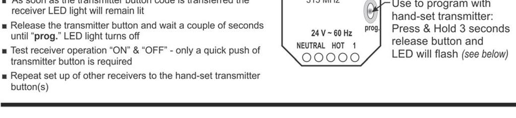
25 fan should be located no more than 120 ft from the furthest heater in the zone. Sufficient air supply must be provided. Exhauster Capacity: USA: Natural or mechanical means shall be provided to supply and exhaust at least 4ft 3 /min/1000btuh (0.38m 3 /min/kw) Natural Gas input of installed heaters [4.5ft 3 / min/1000btuh (0..43m 3 /min/kw) Propane input]. Some local codes may require an interlock to a dedicated exhaust fan. Consult your local code and ANSI Z223.1 latest edition for all venting requirements and practices. Canada: It is required that the heater(s) be electrically interlocked to dedicated exhaust fan(s) by means of an Air Proving Switch. Exhaust fan(s) must be sized to create 300 cfm (8.5 cu m/min) exhaust for every 100,000 Btuh (30 kw) or any portion thereof of total input of installed equipment. Provide combustion and ventilation air supply compatible with exhaust volume. Consult the latest edition of CSA.B149.1 Section REMOTE CONTROL OPTION (Single-Stage Models ONLY) Patio Heaters can be operated using a portable Remote Control Option: JP-1236-RK Remote Receiver Kit (field installed in the heater) JP-1236-HS Remote 4-Button Handset Transmitter The Handset Transmitter is the master component for system setup and operation. It is recommended to have a backup/spare twin handset transmitter in case one is misplaced Handsets plug together to twin a backup handset with the same codes as master In the event of any concern for breach of control security (lost handset), master codes can easily be changed in existing handset(s) on site Unique random signal codes ensures no interference with any neighboring systems JP-1236-KT Wireless Keypad Transmitter (wall mounted at patio) Control up to four heater zones using unique PIN s Requires a Handset Transmitter as master code controller Quick Setup instruction sheets accompany the Remote Receiver Kit and the Handset Transmitter for installation and programming of the system. Layout and Control: Each heater requires its own receiver (JP-1236-RK) Each handset transmitter has 4 channels and can control up to 4 individual heat zones Multiple receivers can be programmed to one common transmitter channel (button) Multiple heaters can be simultaneously activated in one heating zone with one transmitter button If more than 4 heating zones are required, then more than one master handset transmitter is required; two master handsets can control up to 8 heating zones, 25


26 (Single-Stage Models ONLY) 13: 26


27 Single-Stage Models only 27


28 Single-Stage Models only 28


29 Single-Stage Models only 29


30 Single-Stage Models only 30
31 16. SEQUENCE OF OPERATION FOR FENWAL DSI CONTROL Start up - Heat Mode: On a call for heat the Fenwal control will reset, perform a self check routine, flash the diagnostic LED for up to four seconds. The gas valve and spark are energized commencing the trial for ignition period. When flame is detected during the trial for ignition, spark is shutoff immediately and the gas valve remains energized. The thermostat and main burner flame are constantly monitored to assure the system continues to operate properly. When the thermostat is satisfied and the demand for heat ends, the gas valve is de-energized. Flame Failure - Multi Trial Model: Should the main burner fail to light, or the flame is not detected during the first trial for ignition period, the gas valve is de-energized and the control goes through an interpurge delay before another ignition attempt. The control will attempt two additional ignition trials before going into lockout and the valve relay is de-energized. Recovery from lockout requires a manual reset by either resetting the thermostat or removing 24 volts for a period of 5 seconds. If the thermostat is still calling for heat after one hour the control will automatically reset and attempt to ignite the burner again. Flame Failure - Re-Ignition: If the established flame signal is lost while the burner is operating, the control will respond within 0.8 seconds. The HV spark will be energized for a trial ignition period in an attempt to relight the burner. If the burner does not light the control will make two more attempts to relight the burner before de-energizing the gas valve. If the burner does not relight, the control will go into lockout as noted above in Failure to light. If flame is re-established, normal operation resumes. Multi-try models will allow three trials for ignition including interpurge delay between trials. Flame current is the current which passes through the flame from the sensor to ground. The minimum flame current necessary to keep the Fenwal system from lockout is 0.7 microamps (µa). To measure the flame current, connect analog DC microammeter to the FC- FC+ terminals. Meter should read 0.7 µa or higher. If the meter reads below 0 on scale, meter leads are reversed. Disconnect power and reconnect meter leads for proper polarity. 31
32 Cautions: 1. The ceramic insulator of the igniter assembly should not be in or close to the flame. 2. The electrode assembly should not be disassembled and care must be used in making minor gap adjustment. The spark electrode should have a gap spacing of 1/8-3/16 (3.12± 0.81 mm). If this spacing is not correct, the assembly must be carefully adjusted. 3. Exceeding the temperature limits can cause nuisance lockouts and premature electrode failure. The control must be secured in an area that will experience a minimum of vibration and remain below the maximum operating temperature of 160 F. 17. SPARK IGNITION CIRCUIT The step-up transformer in the ignition control provides spark ignition at 30,000 volts (open circuit). To check the spark ignition circuit, proceed as follows. 1 Shut off gas supply to the gas control 2 Disconnect the ignition cable at the ignition control stud terminal to isolate the circuit from the spark igniter or igniter/sensor 3 Prepare a short jumper lead, using heavily insulated wire such as ignition cable CAUTION In the next step, DO NOT allow fingers to touch either the stripped end of the jumper or the stud terminal. This is a very high voltage circuit and electrical shock can result. 1 Perform this test immediately upon energizing the system before the ignition control goes into safety lockout and interrupts the spark circuit. Touch one end of the jumper firmly to the ignition control GND terminal. (DO NOT remove the existing ground lead.) Slowly move the other end of the jumper wire toward the stud terminal on the ignition control to establish a spark. 2 Pull the wire away from the stud and note the length of gap at which spark discontinues. 3 A spark length of 1/8 in. (3mm) or more indicates satisfactory voltage output. If no arc can be established, or the maximum spark is less than 1/8 in. (3mm), and power to the ignition control input terminals was proved, replace the ignition control. 32
33 18-A. WIRING DIAGRAM: 2100 / IO-100 Single-Stage: Fenwal DSI If installing remote control kit JP-1235-RK refer to wiring diagram in the remote control manual Fenwal Control Terminal Designation Error Mode LED Indication TH GND V1 V2 NC S1 Thermostat / 24V Supply Input System Ground Valve Power 24V Supply Neutral Alarm Remote Flame Sensor Internal Control Failure Flame with No Call for heat Ignition Lockout Steady on 2 flashes 3 flashes Fault Conditions: The LED will flash on for 1/4 second, then off for 1/4 second during a fault condition. The pause between fault codes is 3 seconds. 33
34 18-B. WIRING DIAGRAM: 2152 / IO-152 Two-Stage: Fenwal DSI - see control switch wiring next page 34

35 18-C. WIRING DIAGRAM: Two-Stage Switch Control Further information on 2-Stage Control Switches - Page 41 35
36 19. TROUBLESHOOTING GUIDE TURN HEATER ON YES NO *CHECK 120 V AT PRIMARY TRANSFORMER *CHECK VOLTAGE OUT AT SECONDARY. *IF THERE IS NOT 24V TO SECONDARY......REPLACE THE TRANSFORMER 24 VOLTS ±10% TO DSI CONTROL YES NO *CHECK 24V WIRING FROM TRANSFORMER TO IGNITION CONTROL / AND CHECK IF CORRECT GAUGE OF WIRE FOR DISTANCE. *REPLACE WIRES IF NECESSARY. 24 VOLTS OUT FROM CONTROL YES NO *CHECK FOR 24 VAC ACROSS GAS VALVE TERMINALS ON CONTROL. IF NO VOLTAGE,...REPLACE CONTROL. 24 VOLTS AT GAS CONTROL YES NO *ENSURE GAS IS TURNED ON AT VALVE. *CHECK ELECTRICAL CONNECTIONS AT CONTROL & GAS VALVE. *CHECK 24V WIRING CONTINUITY FROM DSI IGNITION CONTROL TO GAS VALVE, RE- PLACE WIRES IF NECESSARY. GAS VALVE OPENS. YES NO IF 24V IS PRESENT AND VALVE DOES NOT OPEN...REPLACE VALVE SPARK ACROSS IGNITER: IS HIGH VOLTAGE SPARK OK? YES MAKE SURE THE MANUAL SWITCH ON THE GAS VALVE IS OPEN AND THAT THERE IS GAS SUPPLY TO THE VALVE. NO *PERFORM IGNITION LEAD TEST DESCRIBED IN SPARK IGNITION CIRCUIT. *CHECK DSI MODULE IGNITION POST FOR DEFECTS. *SPARK IGNITER MAY BE OUT OF POSITION. *CHECK BOOT OF THE IGNITION CABLE FOR SIGNS OF MELTING OR BUCKLING. TAKE PROTECTIVE ACTION TO SHIELD CABLE & BOOT FROM EXCESSIVE TEMPERATURES. *CHECK CERAMIC INSULATOR FOR CRACKS * *CHECK SPARK GAP, 1/8-3/16. *CHECK IGNITION CABLE, AND GROUND WIRE 36
37 MAIN BURNER LIGHTS YES NO *CHECK FOR CORRECT MANIFOLD GAS PRESSURE *CHECK FOR OBSTRUCTION IN GAS SUPPLY OR OR- IFICE (INSECTS, SPIDERS COCOONS ETC.) SPARK STOPS WHEN BURNER LIT. YES NO CHECK FLAME SIGNAL WITH METER FOR 0.7µA. IF READING IS LOW CHECK GAS PRESSURE, IF OK CHANGE SENSOR. CHECK FOR CONTINUITY OR SENSOR CABLE AND GROUND WIRE. CHECK THAT BURNER FLAME COVERS ALL ELEC- TRODES. IF CHECKS ARE OKAY, REPLACE CONTROL MODULE. DOES FLAME REMAIN STABLE AFTER THE SPARK CYCLE IS COM- PLETE. (NO FLAME FAIL) YES NO CHECK SENSOR FLAME SIGNAL WITH METER FOR 0.7µA MINIMUM STEADY READING. IF READING IS LOW CHECK GAS PRESSURE IF OK...CHANGE SENSOR. CHECK FOR CONTINUITY OR SENSOR CABLE AND GROUND WIRE. CHECK THAT BURNER FLAME COVERS ALL ELEC- TRODES. IF CHECKS ARE OKAY, REPLACE CONTROL MODULE. NOTE: IF GROUND IS POOR OR ERRATIC, SHUT- DOWN MAY OCCUR OCCASIONALLY EVEN THOUGH OPERATION IAPPEARS NORMAL AT THE TIME. SYSTEM RUNS UNTIL CALL FOR HEAT ENDS YES NO CHECK FOR PROPER TEMPERATURE CONTROLLER OPERATION. CHECK SENSOR FLAME SIGNAL WITH METER FOR 0.7µA MINIMUM STEADY READING.(REPEAT ABOVE) CALL FOR HEAT ENDS; SYSTEM SHUTS OFF TROUBLE SHOOTING ENDS NO CHECK AND ADJUST TEMPERATURE CONTROLLER SETTING AND CHECK CONTROLLER CONNECTIONS CHECK FOR PINCHED WIRING. REMOVE VALVE LEAD AT CONTROL IF VALVE CLOS- ES, RECHECK TEMPERATURE CONTROLLER AND WIRING; IF VALVE DOES NOT CLOSE REPLACE GAS VALVE. NOTE: IF CONTROL GOES INTO LOCKOUT, THE SYSTEM CAN BE RESET BY INTERRUPTING THE POWER SOURCE 37


38 20. COMMISSIONING REPORT This heater has been factory fired and tested prior to shipment. However, it is not a Plug-in appliance. Commissioning and field adjustment to correct settings is required. COMPLETE THIS COMMISSIONING REPORT AND FILE THIS MANUAL AT SITE FOR FUTURE REFERENCE INSTRUCT THE END USER THAT THIS MANUAL MUST BE KEPT SECURE A QUALIFIED SERVICE TECHNICIAN CALLING FOR TECHNICAL SUPPORT MUST PROVIDE THE INFORMATION FROM THE COMPLETED COMMISSIONING REPORT TECHNICAL SUPPORT: BUSINESS HOURS: 8:30 a.m. to 5:00 p.m. Eastern time Technical commissioning report continues next page. 38


39 HEATER COMMISSIONING TECHNICAL REPORT TO BE COMPLETED BY QUALIFIED GAS FITTER INSTALLER COMPLETE THIS COMMISSIONING REPORT AND FILE THIS MANUAL AT SITE FOR FU- TURE REFERENCE INSTRUCT THE END USER THAT THIS MANUAL MUST BE KEPT SECURE A QUALIFIED SERVICE TECHNICIAN CALLING FOR TECHNICAL SUPPORT MUST PRO- VIDE THE INFORMATION FROM THE COMPLETED COMMISSIONING REPORT 39
40 21. HIGH ALTITUDE INSTALLATION / DERATION This heater not to be installed at altitude above 6,800 feet. USA & Canada: The factory installed orifice for this appliance is approved for altitudes zero to 2000 feet above sea level. When installed above 2000 feet, refer to information below. When this appliance is installed above the standard altitude stipulated the input must be de-rated by 4% for each 1000 ft above sea level. The orifice must be changed according to the chart below - confirm the correct model. Check with your local utility regarding the gas supply and the de-rating of this appliance. FOR USE AT ALTITUDES ABOVE (FEET) Gas Orifice Drill Size 1 / Part # MODEL Supplied USA & CANADA ORIFICE DERATION 2135 / IO-135 NG 2135 / IO-135 LPG 2150 / IO-150 NG 2150 / IO-150 LPG 2152 / IO-152 NG 0 > 2000 > 3000 > 4000 > 5000 > DMS JX-0738-DM 50 DMS JX-0750-DM 31 DMS JX-0731-DM 46 DMS JX-0746-DM 31 DMS JX-0731-DM 41 DMS JX-0741-DM 52 DMS JX-0752-DM 32 DMS JX-0732-DM 48 DMS JX-0748-DM 32 DMS JX-0732-DM 42 DMS JX-0742-DM 53 DMS JX-0753-DM 32 DMS JX-0732-DM 48 DMS JX-0748-DM 32 DMS JX-0732-DM 42 DMS JX-0742-DM 53 DMS JX-0753-DM 32 DMS JX-0732-DM 49 DMS JX-0749-DM 32 DMS JX-0732-DM 43 DMS JX-0743-DM 53 DMS JX-0753-DM 33 DMS JX-0733-DM 49 DMS JX-0749-DM 33 DMS JX-0733-DM 43 DMS JX-0743-DM 53 DMS JX-0753-DM 34 DMS JX-0734-DM 49 DMS JX-0749-DM 34 DMS JX-0734-DM DO NOT INSTALL AT ALTITUDE ABOVE 6,800 FEET 1 Per ANSI Z223.1 (NFPA 54) 40


 JP-1236-KT Wireless Keypad Transmitter (wall mounted at patio) JP-1236-HS 4-Button")
41 22. CONTROL ACCESSORIES Two-Stage Illuminated Switch Gang Assemblies (24Vac capacity): One or a combination of these switch gangs is required to control 2-stage heaters NOTE: Required Switch Sequence Off-On-On is not readily available in the market Illuminated switches indicate low or high stage operation at a glance Each switch gang controls from 1 to 4 two-stage heaters in a zone Combine switch gang assemblies/sizes to achieve optimum control Brushed stainless steel switch plates Standard electrical box supplied to suit each size Factory wired Heater & switch control wiring diagrams - Pages 34 & 35 Field supplied 120/24Vac transformer required upstream of switch gang assembly JM-0201-TS Single Switch Gang Assembly: Control from 1 to 4 Two-Stage Heaters in one Zone JM-0202-TS Double Switch Gang Assembly: Control 2 to 8 Two-Stage Heaters 2 Zones with up to 4 heaters/zone JM-0203-TS Triple Switch Gang Assembly: Control 3 to 12 Two-Stage Heaters 3 Zones with up to 4 heaters/zone Remote Control Options: Single-Stage Heaters only - See details pages 23 to 28 Order items separately JP-1236-RK Remote Receiver Kit (field installed in heater) JP-1236-KT Wireless Keypad Transmitter (wall mounted at patio) JP-1236-HS 4-Button Remote Handset Transmitter 41

 JP-2300-MK WALL MOUNTING ARM KIT")
42 Heater Mounting Hardware Options - Refer to pages 9 to 13 for details NOTE: MOUNT HEATER AT MAXIMUM 30 ANGLE TO AVOID DAMAGE Chain mounting bracket JP-2100-HS is supplied and factory installed as an integral part of the heater. Other optional mounting kits are available: Kits include hardware to fasten bracket to heater. Hardware to fasten to structure is field supplied. JP-2100-MB WALL MOUNTING BRACKET JP-2300-PK POST MOUNTING BRACKET (includes nuts/bolts hardware for post clamp) JP-2300-MK WALL MOUNTING ARM KIT JL-0771-XX 1/2 X 24 STAINLESS STEEL FLEXIBLE GAS CONNECTOR 42
INSTALLATION / OWNER S MANUAL
 Model 2300 Model IO-210 Patio Heater for Outdoor Application and Gas-Fired Luminous (High Intensity) Infrared Heater for Commercial / Industrial Non-Residential Indoor Spaces INSTALLATION / OWNER S MANUAL
INSTALLATION / OWNER S MANUAL
 primoschwank & supraschwank HIGH EFFICIENCY COMBINED INTENSITY Gas-Fired Luminous (High Intensity) Infrared Heaters INSTALLATION / OWNER S MANUAL WARNING Improper installation, adjustment, alteration,
sportschwank HIGH EFFICIENCY INFRARED HEATER INSTALLATION / OWNER S MANUAL
 sportschwank HIGH EFFICIENCY INFRARED HEATER INSTALLATION / OWNER S MANUAL INSTALLER: LEAVE THESE INSTRUCTIONS WITH THE CONSUMER CONSUMER: RETAIN THESE INSTRUCTIONS FOR FUTURE REFERENCE DANGER If you smell
INSTALLATION / OWNER S MANUAL
 ecoschwank-x 36, 52 IL-X 150, 200 Gas-Fired Luminous (High Intensity) Infrared Heaters INSTALLATION / OWNER S MANUAL WARNING Improper installation, adjustment, alteration, service or maintenance can cause
INFRARED RADIANT HEATER RSCA SERIES CERAMIC HEATERS NATURAL GAS PROPANE GAS DATE: PROJECT: ARCHITECT/ENGINEER: CONTRACTOR: SUBMITTED BY:
 INFRARED RADIANT HEATER RSCA SERIES CERAMIC HEATERS NATURAL GAS (CHECK ONE) PROPANE GAS PROJECT: ARCHITECT/ENGINEER: NAME: ADDRESS: NAME: ADDRESS: DATE: CONTRACTOR: SUBMITTED BY: NAME: ADDRESS: EQUIPMENT
LUMINOUS A PATIO HEATER LIKE NO OTHER
 LUMINOUS A PATIO HEATER LIKE NO OTHER Manual for Installation, Operation & Maintenance BPL-HAB20 BPL-HAB40 BPL-HAB50 DANGER If you smell gas: 1. Shut off gas to appliance. 2. Extinguish any open flame.
INSTALLATION / OWNER S MANUAL LUMINOUS GAS FIRED INFRA RED HEATERS
 INSTALLATION / OWNER S MANUAL ECOSCHWANK & ECOSCHWANK X-Series IL & IL X-Series LUMINOUS GAS FIRED INFRA RED HEATERS FOR YOUR SAFETY: Do not store or use gasoline or other flammable vapours and liquids
INSTALLATION / OWNER S MANUAL SCHWANK GAS FIRED INFRA RED HEATERS supraschwank 40 primoschwank 40 SERIES HIGH EFFICIENCY COMBINED INTENSITY
 INSTALLATION / OWNER S MANUAL SCHWANK GAS FIRED INFRA RED HEATERS supraschwank 40 primoschwank 40 SERIES HIGH EFFICIENCY COMBINED INTENSITY FOR YOUR SAFETY: Do not store or use gasoline or other flammable
SERIES VAC Microprocessor-Based Direct Spark Ignition Control FEATURES APPLICATIONS SPECIFICATIONS DESCRIPTION. Export Information (USA)
") R SERIES 35-70 120 VAC Microprocessor-Based Direct Spark Ignition Control F-35-70 November 2015 FEATURES Safe start with DETECT-A-FLAME flame sensing technology Custom pre-purge and inter-purge timings
R SERIES 35-70 120 VAC Microprocessor-Based Direct Spark Ignition Control F-35-70 November 2015 FEATURES Safe start with DETECT-A-FLAME flame sensing technology Custom pre-purge and inter-purge timings
BEACON/MORRIS RBD SERIES INFRARED RADIANT HEATER
 RBDS-1 RBD SERIES CERAMIC HEATERS NATURAL GAS (Check One) PROPANE GAS EQUIPMENT USED: ACCESSORIES: Chain Mounting Kit: Thermostat: Gas Pressure Regulator: Parabolic Extension: Gas Shut-Off Valve: Reverb
OPERATING INSTRUCTIONS MANUAL (Please retain for future reference) F-400T DUAL FUEL CONSTRUCTION HEATER
 F-400T DUAL FUEL CONSTRUCTION HEATER") OPERATING INSTRUCTIONS MANUAL (Please retain for future reference) For F-400T DUAL FUEL CONSTRUCTION HEATER CERTIFIED FOR USE IN CANADA AND U.S.A. As per Standard ANSI Z83.7 2000/ CSA 2.14 2000 Gas Fired
OPERATING INSTRUCTIONS MANUAL (Please retain for future reference) For F-400T DUAL FUEL CONSTRUCTION HEATER CERTIFIED FOR USE IN CANADA AND U.S.A. As per Standard ANSI Z83.7 2000/ CSA 2.14 2000 Gas Fired
Installation, Operation and Service Instructions H RANGE STANDARD EFFICIENCY HIGH INTENSITY HEATERS
 Installation, Operation and Service Instructions H RANGE STANDARD EFFICIENCY HIGH INTENSITY HEATERS WARNINGS WARNING Improper installation, adjustment, alteration, service or maintenance can cause property
OPERATING INSTRUCTIONS MANUAL (Please retain for future reference) F-1500T DUAL FUEL CONSTRUCTION HEATER
 F-1500T DUAL FUEL CONSTRUCTION HEATER") OPERATING INSTRUCTIONS MANUAL (Please retain for future reference) For F-1500T DUAL FUEL CONSTRUCTION HEATER CERTIFIED FOR USE IN CANADA AND U.S.A. As per Standard ANSI Z83.7 2000/ CSA 2.14 2000 Gas Fired
OPERATING INSTRUCTIONS MANUAL (Please retain for future reference) For F-1500T DUAL FUEL CONSTRUCTION HEATER CERTIFIED FOR USE IN CANADA AND U.S.A. As per Standard ANSI Z83.7 2000/ CSA 2.14 2000 Gas Fired
SERIES VAC Microprocessor-Based Intermittent Pilot Ignition Control FEATURES APPLICATIONS SPECIFICATIONS DESCRIPTION
 R SERIES 35-703 120 VAC Microprocessor-Based Intermittent Pilot Ignition Control F-35-703 July 2016 FEATURES Safe start with DETECT-A-FLAME flame sensing technology Custom pre-purge and inter-purge timings
GUIDE SPECIFICATION ADVANCED RADIANT SYSTEMS DU/DUH DUAL OUTPUT RANGE INFRARED TUBE HEATERS
 GUIDE SPECIFICATION ADVANCED RADIANT SYSTEMS DU/DUH DUAL OUTPUT RANGE INFRARED TUBE HEATERS SECTION 15540 FUEL- FIRED HEATERS (Alternate - SECTION 235523 - GAS-FIRED RADIANT HEATERS) This section is based
INSTALLATION / OWNER S MANUAL
 ultraschwank Models: UHE & InfraSave Ultimate Models: EIH HIGH RADIANT OUTPUT LOW INTENSITY TUBE TYPE INFRA RED HEATER INSTALLATION / OWNER S MANUAL WARNING Improper installation, adjustment, alteration,
1.03 DELIVERY, STORAGE, AND HANDLING Heater will be stored to secure against damage and handled per manufacturer s recommendations.
 HVAC Guideline Specifications supraschwank Packaged Luminous Infrared Radiant Gas Heater Combined Intensity (produces both Low and High Intensity radiant output) Commercial/Industrial Applications Size
Owner: Keep this manual in a safe place in order to provide your service technician with the necessary information.
 Sunpak S34-TSH Outdoor Gas Infrared Patio Heater NOT FOR USE IN RESIDENTIAL DWELLINGS Installation, Operation and & Maintenance Instructions NOTE: Heater above shown with optional Face Trim Installer:
SERIES VAC Microprocessor-Based Direct Spark Ignition Control with Inducer Blower Relay FEATURES APPLICATIONS SPECIFICATIONS DESCRIPTION
 R SERIES 35-61 24 VAC Microprocessor-Based Direct Spark Ignition Control with Inducer Blower Relay F-35-61 August 2015 FEATURES Safe start with DETECT-A-FLAME flame sensing technology Custom pre-purge
Line Pressure ( w.c.) Gas Supply Min. Max. Pressure ( w.c.) Natural Gas Propane Gas
 Gas Supply Min. Max. Pressure ( w.c.) Natural Gas Propane Gas") HVAC Guideline Specifications WHISPER-JET: SET SERIES Two Stage Positive Pressure Gas-Fired Infrared Radiant Tube Type Heater Commercial/Industrial Applications Technical Summary Input Range: 80,000/60,000
HVAC Guideline Specifications WHISPER-JET: SET SERIES Two Stage Positive Pressure Gas-Fired Infrared Radiant Tube Type Heater Commercial/Industrial Applications Technical Summary Input Range: 80,000/60,000
Synergy WARNING FOR YOUR SAFETY. High Intensity Infrared Heaters. Installation, Service, and Maintenance Manual COMBUSTION RESEARCH CORPORATION
 COMBUSTION RESEARCH CORPORATION Synergy High Intensity Infrared Heaters Installation, Service, and Maintenance Manual! WARNING Improper installation, adjustment, alteration, service or maintenance can
Installation Requirements for Models:
 900 & 9100 Series Refrigerators Installation Requirements for Models: 9162 9163 9182 9183 962 963 982 983 WARNING Improper installation, adjustment, alteration, service, or maintenance can cause injury
GUIDE SPECIFICATION ADVANCED RADIANT SYSTEMS KMI GoGas RANGE HIGH EFFICIENCY, HIGH INTENSITY INFRARED HEATERS
 GUIDE SPECIFICATION ADVANCED RADIANT SYSTEMS KMI GoGas RANGE HIGH EFFICIENCY, HIGH INTENSITY INFRARED HEATERS SECTION 15540 - FUEL - FIRED HEATERS (Alternate - SECTION 235523 - GAS-FIRED RADIANT HEATERS)
OPERATING INSTRUCTIONS MANUAL (Please retain for future reference) F-1000T DUAL FUEL CONSTRUCTION HEATER
 F-1000T DUAL FUEL CONSTRUCTION HEATER") OPERATING INSTRUCTIONS MANUAL (Please retain for future reference) For F-1000T DUAL FUEL CONSTRUCTION HEATER CERTIFIED FOR USE IN CANADA AND U.S.A. As per Standard ANSI Z83.7 2000/ CSA 2.14 2000 Gas Fired
OPERATING INSTRUCTIONS MANUAL (Please retain for future reference) For F-1000T DUAL FUEL CONSTRUCTION HEATER CERTIFIED FOR USE IN CANADA AND U.S.A. As per Standard ANSI Z83.7 2000/ CSA 2.14 2000 Gas Fired
Installation, Operation and Service Instructions HD RANGE SINGLE STAGE DIRECT SPARK HIGH INTENSITY HEATERS
 Installation, Operation and Service Instructions HD RANGE SINGLE STAGE DIRECT SPARK HIGH INTENSITY HEATERS WARNINGS WARNING Improper installation, adjustment, alteration, service or maintenance can cause
OPERATING INSTRUCTIONS MANUAL (Please retain for future reference) FVN/P-400 INDIRECT FIRED SPACE HEATERS
 FVN/P-400 INDIRECT FIRED SPACE HEATERS") OPERATING INSTRUCTIONS MANUAL (Please retain for future reference) For FVN/P-400 INDIRECT FIRED SPACE HEATERS CERTIFIED FOR USE IN CANADA AND U.S.A. As per Standard ANSI Z83.7/CSA 21.4 2000 Gas Fired Construction
OPERATING INSTRUCTIONS MANUAL (Please retain for future reference) For FVN/P-400 INDIRECT FIRED SPACE HEATERS CERTIFIED FOR USE IN CANADA AND U.S.A. As per Standard ANSI Z83.7/CSA 21.4 2000 Gas Fired Construction
Owner: Keep this manual in a safe place in order to provide your service technician with the necessary information.
 Sunpak S34 TSR Outdoor Gas Infrared Patio Heater Installation, Operation and & Maintenance Instructions Installer: Please take the time to read and understand these instructions prior to installation.
INSTALLATION AND OPERATION INSTRUCTIONS
 INSTALLATION AND OPERATION INSTRUCTIONS OWNER / INSTALLER: For your safety this manual must be carefully and thoroughly read and understood before installing, operating or servicing this heater. INFRARED
Sunpak Models S25 & S34
 Sunpak Models S25 & S34 Outdoor Gas Infrared Patio Heater NOT FOR USE IN RESIDENTIAL DWELLINGS Installation, Operation and & Maintenance Instructions Installer: Please take the time to read and understand
Installer: Leave this manual with the appliance. Consumer: Retain this manual for future reference.
 Installer: Leave this manual with the appliance. Consumer: Retain this manual for future reference. Operating Instructions and Owner s Manual READ INSTRUCTIONS CAREFULLY: Read and follow all instructions.
STS-JZ (premierschwank) POSITIVE PRESSURE SERIES GAS FIRED INFRA-RED TUBE HEATERS
 POSITIVE PRESSURE SERIES GAS FIRED INFRA-RED TUBE HEATERS") SUBMITTAL DATA (premierschwank) POSITIVE PRESSURE SERIES GAS FIRED INFRA-RED TUBE HEATERS PROJECT: ENGINEER: CONTRACTOR: DISTRIBUTOR: SCHWANK MODEL #: FUEL: APPROVED BY: DATE: APPROVAL #: 1 Submittal NOTICE:
SUBMITTAL DATA (premierschwank) POSITIVE PRESSURE SERIES GAS FIRED INFRA-RED TUBE HEATERS PROJECT: ENGINEER: CONTRACTOR: DISTRIBUTOR: SCHWANK MODEL #: FUEL: APPROVED BY: DATE: APPROVAL #: 1 Submittal NOTICE:
SERIES 35-63J APPLICATIONS FEATURES SPECIFICATIONS AGENCY CERTIFICATIONS
 SERIES 35-63J INSTALLATION INSTRUCTIONS FOR REPLACING JOHNSON CONTROLS G77X AND OTHER MODELS WITH FENWAL SERIES 35-63J IP IGNITION CONTROL APPLICATIONS The Fenwal 35-63J series Intermittent Pilot Ignition
Series RE Infrared Heater
 Series RE Infrared Heater Installation, Operation and Service Instructions WARNING: If the information in these instructions are not followed exactly, a fire or explosion may result causing property damage,
INSTALLATION AND OPERATION INSTRUCTIONS
 INSTALLATION AND OPERATION INSTRUCTIONS OWNER / INSTALLER: For your safety this manual must be carefully and thoroughly read and understood before installing, operating or servicing this heater. INFRARED
Radiant Patio Heater. Performance that outshines. Manual for Installation, Operation & Maintenance
 Series GA301 Radiant Patio Heater Performance that outshines Manual for Installation, Operation & Maintenance DANGER If you smell gas: 1. Shut off gas to appliance. 2. Extinguish any open flame. 3. If
THC 85 / 175 INDUSTRIAL / COMMERCIAL SPACE HEATER
 THC 85 / 175 INDUSTRIAL / COMMERCIAL SPACE HEATER Certified to / Certifié à CGA 2.14 M2000 Conforms to / Conforme à ANSI std Z83.7 2000 Suitable for indoor or outdoor installation / Unvented / Unattended
INSTALLATION AND OPERATION INSTRUCTIONS
 INSTALLATION AND OPERATION INSTRUCTIONS OWNER / INSTALLER: For your safety this manual must be carefully and thoroughly read and understood before installing, operating or servicing this heater. MILLIVOLT
Internet Version for Reference Only INDUCED DRAFT COMMERCIAL WATER HEATERS SUPPLEMENT INSTRUCTIONS TO PART #
 INDUCED DRAFT COMMERCIAL WATER HEATERS SUPPLEMENT INSTRUCTIONS TO PART #238-39387-00 THIS INSTRUCTION SUPPLEMENT IS ONLY INTENDED TO GIVE INSTALLATION INSTRUCTIONS AND INFORMATION RELATED TO THE INDUCED
Owner: Keep this manual in a safe place in order to provide your service technician with the necessary information.
 Sunpak S34-TSR Outdoor Gas Infrared Patio Heater NOT FOR USE IN RESIDENTIAL DWELLINGS Installation, Operation and & Maintenance Instructions Note: Heater above shown with optional Face Trim Installer:
USER S INFORMATION MANUAL
 USER S INFORMATION MANUAL HOT WATER HEATING BOILERS DOMESTIC WATER HEATERS 150,000-300,000 Btu/hr MODELS EB-EWU-02 IMPORTANT INSTALLER - AFFIX INSTALLATION MANUAL ADJACENT TO THE BOILER CONSUMER - RETAIN
INSTALLATION AND OPERATION INSTRUCTIONS
 INSTALLATION AND OPERATION INSTRUCTIONS OWNER / INSTALLER: For your safety this manual must be carefully and thoroughly read and understood before installing, operating or servicing this heater. INFRARED
BGH Series Hot Surface Ignition Control
 Installation Instructions BGH Series Issue Date April 14, 2011 BGH Series Hot Surface Ignition Control Application The BASO Gas Products BGH Series Hot Surface Ignition (HSI) control is microprocessor
Owner s Guide Installation & Operation
 Owner s Guide Installation & Operation Hot Top HHT Series Hestan Commercial Corporation 3375 E. La Palma Ave Anaheim, CA 92806 (888) 905-7463 RETAIN THIS MANUAL FOR FUTURE REFERENCE P/N 002130 REV 1 IMPORTANT
Outdoor Flame Heater
 Model Outdoor Flame Heater Owner s Manual Read these instructions before lighting this appliance. DANGER If you smell gas: 1. Shut off gas to the appliance. 2. Extinguish any open flame. 3. If odor continues,
OPERATING INSTRUCTIONS MANUAL (Please retain for future reference) FVN/P-400 INDIRECT FIRED SPACE HEATERS
 FVN/P-400 INDIRECT FIRED SPACE HEATERS") OPERATING INSTRUCTIONS MANUAL (Please retain for future reference) For FVN/P-400 INDIRECT FIRED SPACE HEATERS CERTIFIED FOR USE IN CANADA AND U.S.A. As per Standard ANSI Z83.7/CSA 21.4 2000 Gas Fired Construction
OPERATING INSTRUCTIONS MANUAL (Please retain for future reference) For FVN/P-400 INDIRECT FIRED SPACE HEATERS CERTIFIED FOR USE IN CANADA AND U.S.A. As per Standard ANSI Z83.7/CSA 21.4 2000 Gas Fired Construction
Installation/Operating Instructions for: The Equator. H.I. Series Indoor/Outdoor Infrared Patio Heaters
 E asy R adiant W orks 12288 S id e R oa d 22, W ain fleet, O n ta rio, C anad a L 0S 1V 0 P h on e 905 89 9 3473 F ax 905 899 2262 w w w.easy rad iantw orks.co m em ail erw @ vaxxine.com Installation/Operating
THC-175DF INDUSTRIAL / COMMERCIAL SPACE HEATER. Certified to / Certifié à CGA 2.14 M2011 Conforms to / Conforme à ANSI std Z83.
 THC-175DF INDUSTRIAL / COMMERCIAL SPACE HEATER Certified to / Certifié à CGA 2.14 M2011 Conforms to / Conforme à ANSI std Z83.7 2011 Suitable for indoor or outdoor installation / Unvented / Unattended
FOR YOUR SAFETY. Applies to: Models RIH, RIHV, RIHVN, and RIHVL Gas-Fired High-Intensity Infrared Heaters. Models RIH/RIHV
 Form I-RIH (10-14) Obsoletes Form I-RIH (Version E) Installation/Operation/Maintenance Applies to: Models RIH, RIHV, RIHVN, and RIHVL Gas-Fired High-Intensity Infrared Heaters Models RIH/RIHV WARNING Improper
SERIES VAC Microprocessor-Based Hot Surface Ignition Control FEATURES APPLICATIONS SPECIFICATIONS DESCRIPTION AGENCY CERTIFICATIONS
 SERIES 35-65 24 VAC Microprocessor-Based Hot Surface Ignition Control F-35-65 August 2015 FEATURES Safe start with DETECT-A-FLAME flame sensing technology Custom pre-purge and inter-purge timings* 120/240
CBO-750 HYBRID-R OVEN Instructions Manual
 CBO-750 HYBRID-R OVEN Instructions Manual ELECTRICAL DIAGRAM IS LOCATED BEHIND FRONT PANEL THIS OVEN MAY BE OPERATED OUTDOORS. ELECTRICAL DIAGRAMS ARE LOCATED BEHIND FRONT PANEL. KEEP THIS MANUAL FOR FUTURE
Series GR/ET Infrared Heater
 Series GR/ET Infrared Heater Installation, Operation and Service Instructions WARNING: If the information in these instructions are not followed exactly, a fire or explosion may result causing property
Owner s Guide Installation & Operation
 Owner s Guide Installation & Operation Char Broiler HCH Series Hestan Commercial Corporation 3375 E. La Palma Ave Anaheim, CA 92806 (888) 905-7463 RETAIN THIS MANUAL FOR FUTURE REFERENCE P/N 002134 REV
INSTALLATION OPERATING, AND SERVICE INSTRUCTIONS FOR SUBURBAN DIRECT VENT SEALED COMBUSTION GAS HEATER MODEL GT-10D
 INSTALLATION OPERATING, AND SERVICE INSTRUCTIONS FOR SUBURBAN DIRECT VENT SEALED COMBUSTION GAS HEATER MODEL GT-10D FOR YOUR SAFETY FOR YOUR SAFETY IF YOU SMELL GAS: DO NOT STORE OR USE GASOLINE 1. OPEN
THC 85 INDUSTRIAL / COMMERCIAL SPACE HEATER
 A Division of THC 85 INDUSTRIAL / COMMERCIAL SPACE HEATER Certified to / Certifié à CGA 2.14 M2000 Conforms to / Conforme à ANSI std Z83.7 2000 Suitable for indoor or outdoor installation / Unvented /
THC 85N / 175N INDUSTRIAL / COMMERCIAL SPACE HEATER
 THC 85N / 175N INDUSTRIAL / COMMERCIAL SPACE HEATER Certified to / Certifié à CGA 2.14 M2000 Conforms to / Conforme à ANSI std Z83.7 2000 Suitable for indoor or outdoor installation / Unvented / Unattended
Installation, Operation and Service Instructions RS RANGE RESIDENTIAL INFRARED HEATERS
 Installation, Operation and Service Instructions RS RANGE RESIDENTIAL INFRARED HEATERS WARNINGS WARNING Improper installation, adjustment, alteration, service or maintenance can cause property damage,
THC 85N / 175N INDUSTRIAL / COMMERCIAL SPACE HEATER
 THC 85N / 175N INDUSTRIAL / COMMERCIAL SPACE HEATER Certified to / Certifié à CGA 2.14 M2000 Conforms to / Conforme à ANSI std Z83.7 2000 Suitable for indoor or outdoor installation / Unvented / Unattended
INSTALLATION AND OPERATION INSTRUCTIONS
 INSTALLATION AND OPERATION INSTRUCTIONS OWNER / INSTALLER: For your safety this manual must be carefully and thoroughly read and understood before installing, operating or servicing this heater. STARGLO
southbend A MIDDLEBY COMPANY INSTALLATION AND OPERATION MANUAL CG214 (E) CG314 (E) CG414 (E) CG220 (E) CG320 (E) CG325 (E) GAS BOILERS MODELS:
 CG314 (E) CG414 (E) CG220 (E) CG320 (E) CG325 (E) GAS BOILERS MODELS:") INSTALLATION AND OPERATION MANUAL GAS BOILERS MODELS: CG214 (E) CG314 (E) CG414 (E) CG220 (E) CG320 (E) CG325 (E) southbend A MIDDLEBY COMPANY 1100 Old Honeycutt Road Fuquay-Varina, NC 27526 (919) 552-9161
INSTALLATION AND OPERATION MANUAL GAS BOILERS MODELS: CG214 (E) CG314 (E) CG414 (E) CG220 (E) CG320 (E) CG325 (E) southbend A MIDDLEBY COMPANY 1100 Old Honeycutt Road Fuquay-Varina, NC 27526 (919) 552-9161
INSTALLATION AND OPERATION INSTRUCTIONS
 INSTALLATION AND OPERATION INSTRUCTIONS OWNER / INSTALLER: For your safety this manual must be carefully and thoroughly read and understood before installing, operating or servicing this heater. INFRARED
OPERATING INSTRUCTIONS AND OWNER S MANUAL
 OPERATING INSTRUCTIONS AND OWNER S MANUAL MR. HEATER READ INSTRUCTIONS CAREFULLY: Read and follow all instructions. Place instructions in a safe place for future reference. Do not allow anyone who has
Owner s Information Manual
 48ES---A and 48VL---A Comfort and Performance 13 and 14 SEER Single Packaged Air Conditioner and Gas Furnace System With Puron (R---410A) Refrigerant Single and Three Phase 2---5 Nominal Tons (Sizes 24---60)
SERVICE FACTS WARNING M801-SF-1C. Gas Furnaces Upflow & Downflow Induced Draft 1 Stage Heat Models: DISCONNECT POWER BEFORE SERVICING M801P040AU24AA
 SERVICE FACTS Gas Furnaces Upflow & Downflow Induced Draft Stage Heat Models: M80P00AU2AA M80P060AU2AA M80P060AU36AA M80P080BU36AA M80P080BU8AA M80P00BU36AA M80P00CU8AA M80P00CU60AA M80PDU60AA M80P0DU60AA
INFRARED RADIANT TUBE HEATER RSTP15C NATURAL GAS RSTP17C
 PROJECT: INFRARED RADIANT TUBE HEATER RSTP15C NATURAL GAS (CHECK ONE) RSTP17C NAME: ADDRESS: (CHECK ONE) PROPANE GAS DATE: ARCHITECT/ENGINEER: CONTRACTOR: SUBMITTED BY: NAME: ADDRESS: NAME: ADDRESS: EQUIPMENT
Multi-Function Cooktop
 INSTALLATION GUIDE Multi-Function Cooktop Contents Wolf Multi-Function Cooktop.................... 3 Multi-Function Cooktop Specifications............ 4 Multi-Function Cooktop Installation...............
THC- 355DF (Dual Fuel)
") OPERATING INSTRUCTIONS MANUAL THC- 355DF (Dual Fuel) INDUSTRIAL / COMMERCIAL DIRECTIONAL SPACE HEATER (OPERATOR MUST RETAIN FOR FUTURE REFERENCES) Certified to / Certifié à ANSI std Z83.7 2000 Suitable
OPERATING INSTRUCTIONS MANUAL THC- 355DF (Dual Fuel) INDUSTRIAL / COMMERCIAL DIRECTIONAL SPACE HEATER (OPERATOR MUST RETAIN FOR FUTURE REFERENCES) Certified to / Certifié à ANSI std Z83.7 2000 Suitable
S150 S300 CONSTRUCTION HEATERS. Rev: August 15, 2008 SERVICE AND MAINTENANCE MANUAL No PLEASE RETAIN FOR FUTURE REFERENCE PRODUCTS
 S150 & S300 CONSTRUCTION HEATERS Rev: 2.7.2 August 15, 2008 SERVICE AND MAINTENANCE MANUAL No. 934-6637 PLEASE RETAIN FOR FUTURE REFERENCE PRODUCTS A DIVISION OF HAUL-ALL EQUIPMENT LTD. 4115-18 Avenue
Model No: Little Devil II (inc ss)
") GAS HEATER Model No: Little Devil II (inc ss) PART NO: 6926020, 6926025 (SS) OPERATION & MAINTENANCE INSTRUCTIONS LS1213 INTRODUCTION Thank you for purchasing this CLARKE Gas Heater. Before attempting
GAS HEATER Model No: Little Devil II (inc ss) PART NO: 6926020, 6926025 (SS) OPERATION & MAINTENANCE INSTRUCTIONS LS1213 INTRODUCTION Thank you for purchasing this CLARKE Gas Heater. Before attempting
User Manual. 110 Cup (55 Cup Raw) Gas Rice Cooker. Model: 177GRCLP, 177GRCNAT 12/2018. Please read and keep these instructions. Indoor use only.
 Gas Rice Cooker. Model: 177GRCLP, 177GRCNAT 12/2018. Please read and keep these instructions. Indoor use only.") 110 Cup (55 Cup Raw) Gas Rice Cooker Intertek 5010781 Conforms to ANSI STD Z83.11-2016 Model: 177GRCLP, 177GRCNAT 12/2018 FOR YOUR SAFETY Do not store or use gasoline or other flammable vapors or liquids
110 Cup (55 Cup Raw) Gas Rice Cooker Intertek 5010781 Conforms to ANSI STD Z83.11-2016 Model: 177GRCLP, 177GRCNAT 12/2018 FOR YOUR SAFETY Do not store or use gasoline or other flammable vapors or liquids
DESIGN CLASS FUNCTION
 PROFESSIONAL QUALITY COOKING EQUIPMENT INSTALLATION MANUAL FOR PERFORMER SLIDE-IN COOK TOPS MODEL NUMBERS: AROBSCT-424, AROBSCT-242GD, AROBSCT-24X2GR, AROBSCT-430, AROBSCT-636, AROBSCT-436GD, AROBSCT-436GR,
INSTALLATION AND OPERATION MANUAL GAS SKILLETS MODELS: GTS-30 GTS-40
 INSTALLATION AND OPERATION MANUAL GAS SKILLETS MODELS: GTS-30 GTS-40 CROWN FOOD SERVICE EQUIPMENT LTD. 70 OAKDALE ROAD, DOWNSVIEW, (TORONTO), ONTARIO, CANADA, M3N 1V9 TELEPHONE: (416) 746-2358, FAX: (416)
SERVICE AND INSTALLATION MANUAL MODELS HDO(H) OIL FOR YOUR SAFETY
 OIL FOR YOUR SAFETY") Bousquet Technologies Inc. 2121, Nobel, Ste Julie, Quebec, Canada, J3E1Z9 SERVICE AND INSTALLATION MANUAL MODELS HDO(H) OIL Oil-Fired air heater for industrial and commercial use. FOR YOUR SAFETY Do not
Bousquet Technologies Inc. 2121, Nobel, Ste Julie, Quebec, Canada, J3E1Z9 SERVICE AND INSTALLATION MANUAL MODELS HDO(H) OIL Oil-Fired air heater for industrial and commercial use. FOR YOUR SAFETY Do not
OPERATING INSTRUCTIONS MANUAL (Please retain for future reference) FVN/P-400 INDIRECT FIRED SPACE HEATERS
 FVN/P-400 INDIRECT FIRED SPACE HEATERS") OPERATING INSTRUCTIONS MANUAL (Please retain for future reference) For FVN/P-400 INDIRECT FIRED SPACE HEATERS CERTIFIED FOR USE IN CANADA AND U.S.A. As per Standard ANSI Z83.7/CSA 21.4 2000 Gas Fired Construction
OPERATING INSTRUCTIONS MANUAL (Please retain for future reference) For FVN/P-400 INDIRECT FIRED SPACE HEATERS CERTIFIED FOR USE IN CANADA AND U.S.A. As per Standard ANSI Z83.7/CSA 21.4 2000 Gas Fired Construction
Dashley Outdoor Fire Table
 Dashley Outdoor Fire Table MODEL N0. 085-557-8 L-FT047PST-F ASSEMBLY INSTRUCTIONS Toll-free 888 670-6684 IMPORTANT: Please read this manual carefully before beginning assembly of this product. Keep this
CINCINNATI, OH USA
 INSTRUCTION MANUAL Part No. 89731 Revised October 1997 CINCINNATI, OH 45241-4807 USA GAS SAFETY PRECAUTIONS Instructions on what to do when a user smells gas can be obtained from the local gas supplier.
PH Series Manual WARNING. Detroit Radiant Products Co. Installation, Operation, Maintenance and Parts. For Your Safety
 Detroit Radiant Products Co. PH Series Manual Installation, Operation, Maintenance and Parts All persons involved with the installation, operation and maintenance of the heater system must read and understand
USER MANUAL Gas Countertop Charbroilers
 Gas Countertop Charbroilers REVISED 2/209 382799 LAVA BRIQUETTE MODELS: 35CLCPG5NL, 35CLCPG24NL, 35CLCPG36NL, 35CLCPG48NL, 35CLCPG60NL, 35CLCPG72NL Congratulations on your purchase of Cooking Performance
STAR-MAX PROPANE GAS GRIDDLE
 Star Manufacturing International Inc. 10 Sunnen Drive St. Louis, MO 63143 Phone: (314) 781-2777 Fax: (314) 781-3636 Installation and Operating Instructions 2M-Z3793 Rev. B 3/28/03 STAR-MAX PROPANE GAS
MODELS LFP4218/LFP6018 TOP VENT GAS FIREPLACE
 MODELS LFP4218/LFP6018 TOP VENT GAS FIREPLACE PFS APPROVED FOR NATURAL GAS OR PROPANE GAS Z21.50-2014 If your plans do not allow for the venting system as outlined previously in the installing chimney/vent
Bosch 80% AFUE Gas Furnace BGS80 Model
 Bosch 80% AFUE Gas Furnace BGS80 Model 4-Way Multipoise Category I Fan-Assisted Furnace User's Information Manual 3124627 2 Bosch 80% AFUE Gas Furnace User's Information Manual Data subject to change 06.2018
Fig. 1 - Unit PGD4, PGS4, WPG4
 OWNER S MANUAL 14 SEER Single -Package Air Conditioner and Gas Furnace System with R -410A Refrigerant Single Phase 2 to 5 Nominal Tons Three Phase 3 to 5 Nominal Tons PGD4andPGS4SeriesE,WPG4SeriesB Fig.
SERIES EvenTube INFRARED HEATER. Installation, Operation and Service Instructions. Model ETS Infrared Patio Heater. Two-Stage
 Installation, Operation and Service Instructions INFRARED HEATER SERIES EvenTube Model ETS Infrared Patio Heater Two-Stage WARNING: FOR OUTDOOR USE ONLY WARNING Improper installation, adjustment, alteration,
Hot Surface Ignition (HSI) System Booklet
 System Booklet") Hot Surface Ignition (HSI) System Booklet American Dryer Corporation 88 Currant Road Fall River MA 02720-4781 Telephone: (508) 678-9000 / Fax: (508) 678-9447 E-mail: techsupport@amdry.com 010298MFM/abe
Hot Surface Ignition (HSI) System Booklet American Dryer Corporation 88 Currant Road Fall River MA 02720-4781 Telephone: (508) 678-9000 / Fax: (508) 678-9447 E-mail: techsupport@amdry.com 010298MFM/abe
For use with models: PGM304-1, versions M-B PGM365-1, versions M-E, M-F & M-G
 PGM-1 Cooktops For use with models: PGM304-1, versions M-B PGM365-1, versions M-E, M-F & M-G Install ation Instructions Part No. 65476 Rev. B Table of Contents Appliance Safety...1 Important Safety Instructions...2
PH Series Manual WARNING. Detroit Radiant Products Co. Installation, Operation, Maintenance and Parts. For Your Safety
 Detroit Radiant Products Co. PH Series Manual Installation, Operation, Maintenance and Parts All persons involved with the installation, operation and maintenance of the heater system must read and understand
ELECTRIC UNIT HEATER REGULAR DUTY
 ELECTRIC UNIT HEATER REGULAR DUTY Installation Form RGM 428 (MI500 Revision 0) APPLIES TO: Model EGE INDEX (by page number) Clearance to Combustibles... 3 Dimensions... 4 Electrical... 4 Fan Motor... 4
TERRACE AND PATIO HEATER
 TERRACE AND PATIO HEATER USER INSTALLATION AND OPERATION GUIDE INDEX General and specifications.1,2 Security and caution.. 3 Tools and accessories required 5 Assembly instructions 5-7 Operation (Lighting
GUIDE SPECIFICATION ADVANCED RADIANT SYSTEMS SL/SLV SIRIUS LINEAR RANGE HIGH EFFICIENCY CONTINUOUS INFRARED SYSTEMS
 GUIDE SPECIFICATION ADVANCED RADIANT SYSTEMS SL/SLV SIRIUS LINEAR RANGE HIGH EFFICIENCY CONTINUOUS INFRARED SYSTEMS SECTION 15540 FUEL- FIRED HEATERS (Alternate - SECTION 235523 - GAS-FIRED RADIANT HEATERS)
USER S INFORMATION MANUAL
 USER S INFORMATION MANUAL UPFLOW/HORIZONTAL & DOWNFLOW TWO STAGE INDUCED DRAFT GAS FURNACES Recognize this symbol as an indication of Important Safety Information If the information in this manual is not
INSTALLATION GUIDE Dual Fuel Ranges
 INSTALLATION GUIDE Dual Fuel Ranges Contents Wolf Dual Fuel Ranges......................... 3 Safety Instructions............................ 4 Dual Fuel Range Specifications.................. 5 Dual Fuel
CYLINDER NOT INCLUDED
 OPERATING INSTRUCTIONS AND OWNER S MANUAL Model # HS125NG / MH125LP / HS125LP READ INSTRUCTIONS CAREFULLY: Read and follow all instructions. Place instructions in a safe place for future reference. Do
WARNING. SPECIFICATIONS: Completely Self-contained Rain Protected Wind Resistant No Electrical Required WARNING FOR OUTDOOR USE ONLY!
 SPECIFICATIONS: Completely Self-contained Rain Protected Wind Resistant No Electrical Required 100% Safety Shutoff Control 40,000 BTUH Input Rating Constant Pilot Propane Gas DANGER If you smell gas: 1.
WARNING WARNING. Infrared Dynamics SUNPAK. Gas-Fired, Unvented High-Intensity Infrared Heaters. Installation, Operation & Maintenance Manual
 FOR YOUR SAFETY: If you smell gas: 1. Open windows. 2. DO NOT try to light any appliance 3. DO NOT use electrical switches 4. DO NOT use any telephone in your building 5. Leave the building 6. Immediately
Owner s Guide Installation & Operation
 Owner s Guide Installation & Operation Fryer HFR Series Hestan Commercial Corporation 3375 E. La Palma Ave Anaheim, CA 92806 (888) 905-7463 RETAIN THIS MANUAL FOR FUTURE REFERENCE P/N 002137 REV 1 IMPORTANT
Indirect gas-fired air heater
 Indirect gas-fired air heater SERIES HD INSTALLATION AND SERVICE MANUAL MANUFACTURED BY : BROTHERS LIMITED WARNING Improper installation, modification, adjustment or maintenance may cause damage, injury
GAS COOKTOP MODELS: CTG365D, CTG305D, CTG304D TO REDUCE THE RISK OF FIRE, ELECTRIC SHOCK, OR INJURY TO PERSONS, OBSERVE THE FOLLOWING
 By CNP INDUSTRIES, INC. P.O. Box 18645 Anaheim, Ca 92817 (877) 387-6721 INSTALLATION INSTRUCTIONS GAS COOKTOP MODELS: CTG365D, CTG305D, CTG304D IMPORTANT: Before beginning installation please read these
OPERATING INSTRUCTIONS MANUAL (Please retain for future reference) FVO-400 INDIRECT FIRED SPACE HEATERS
 FVO-400 INDIRECT FIRED SPACE HEATERS") OPERATING INSTRUCTIONS MANUAL (Please retain for future reference) For FVO-400 INDIRECT FIRED SPACE HEATERS CERTIFIED FOR USE IN CANADA AND U.S.A. As per CSA B140.8 Portable Oil Fired Heaters / CSA B140.02003
OPERATING INSTRUCTIONS MANUAL (Please retain for future reference) For FVO-400 INDIRECT FIRED SPACE HEATERS CERTIFIED FOR USE IN CANADA AND U.S.A. As per CSA B140.8 Portable Oil Fired Heaters / CSA B140.02003
DESIGN CLASS FUNCTION
 PROFESSIONAL QUALITY COOKING EQUIPMENT INSTALLATION MANUAL FOR MEDALLION DUAL FUEL RANGES MODEL NUMBERS: ARR-304DF, ARR-366DF, ARR-364GDDF, ARR-364GRDF, ARR-486GDDF, ARR-486GRDF, ARR-4822GDDF, ARR-484X2GRDF,
INFRARED RADIANT TUBE HEATER
 INFRARED RADIANT TUBE HEATER LTU 40 250 SERIES PROJECT: ADDRESS: ARCHITECT/ENGINEER: ADDRESS: CONTRACTOR: ADDRESS: SUBMITTED BY: N-NATURAL GAS (CHECK ONE) L-PROPANE GAS EQUIPMENT USED: 5-SINGLE STAGE (CHECK