IMPORTANT: SAVE THESE INSTRUCTIONS.
|
|
|
- Barry Simpson
- 5 years ago
- Views:
Transcription


1 FREE STANDING RANGE GAS AND ELECTRIC APPLIANCES EUROCHEF USA inc. MOD.: VEFSGGL65 - Oven Gas Range VEFSGEL65 - Oven Dual Fuel Range INSTRUCTION GUIDE, INSTALLATION AND MAINTENANCE IMPORTANT: SAVE THESE INSTRUCTIONS. IMPORTANT SAFETY INSTRUCTIONS Read and follow all instructions before using this appliance to prevent the potential risk of fire, electrical shock, personal injury or damage to the appliance as a result of improper usage of the appliance. Use appliance only for its intended purpose as described in this manual. The Installer must leave these instructions with the appliance and to the consumer to retain them for future reference. WARNING: If the information in this manual is not followed exactly, a fire or explosion may result causing property damage, personal injury or death. Do not store or use gasoline or other flammable vapors and liquids in the vicinity of this appliance. WHAT TO DO IF YOU SMELL GAS: - Do not to light any appliance. - Do not touch any electrical switch. - Do not use any phone in your building. - Immediately call your gas supplier from a neighbour s phone. Follow the gas supplier s instructions. - If you cannot reach your gas supplier, call the fire department. Installation and service must be performed by a qualified installer, service agency or the gas supplier CU 36P VERONA PRO
2 WARNING: To avoid risk of property damage, personal injury or death; follow information in this manual exactly to prevent a fire or explosion. DO NOT store or use gasoline or other flammable vapors and liquids in the vicinity of this or any appliance. To ensure proper and safe operation: Appliance must be properly installed and grounded by a qualified installer. Have the installer show you the location of the gas shut off valve and how to shut it off in an emergency. Always disconnect power to appliance before servicing. IMPORTANT SAFEGUARDS. Warning: To reduce risk of tipping of the appliance from abnormal usage or by excessive loading of the oven door, the appliance must be secured by a properly installed anti-tip device. To check if the device is installed properly, remove lower storage drawer and look beneath the lower frame sheet at the back area, and verify that the anti-tip device plate is properly engaged in the rear cover slot just above the frame sheet. You should check this anytime the range has been moved. Proper installation. Be sure your appliance is properly installed and grounded by a qualified technician. Do not leave children alone. Children should not be left alone or unattended in area where appliance is in use. They should never be allowed to sit or stand on any part of the appliance. Wear proper apparel. Loose fitting or hanging garments should never be worn while using the appliance CU 36P VERONA PRO
3 User servicing. Do not repair or replace any part of the appliance unless specifically recommended in the manual. All other servicing should be referred to a qualified technician. Storage in or on appliance. Flammable materials should not be stored in an oven or near surface units. Do not use water on grease fires. Smother fire or flame by using dry chemical or foam-type extinguisher. Use only dry potholders. Moist or damp potholders on hot surfaces may result in burns from steam. Do not let potholder touch heating elements. Do not use a towel or other bulky cloth. Use proper pan size. This appliance is equipped with one or more surface units of different size. Select utensils having flat bottoms large enough to cover the surface unit gas burner. The use of undersized utensils will expose flame out of the pot bottom to direct contact and may result in ignition of clothing. Proper relationship of utensil to burner will also improve efficiency. Never leave surface units unattended at high heat settings. Boil-over causes smoking and greasy spill-over that may ignite. Protective liners. Do not use aluminium foil to line surface unit drip areas and oven bottoms. Glazed cooking utensils. Only certain types of glass, glass/ceramic, ceramic, earthenware, or other glaze utensils are suitable for cooking range use without breaking due to the sudden change in temperature. Utensil handles should be turned inward and not extended over adjacent surface units. To reduce the risk of burns, ignition of flammable materials, and spillage due to unintentional contact with the utensil, the handle of a utensil should be positioned so that it is turned inward, and does not extend over adjacent surface units CU 36P VERONA PRO
4 Do not touch surface units or areas near units as well as oven gas burner or interior oven surface. Surface units and oven gas burners may be hot even though they have no flame. Areas near surface units and interior oven surfaces may become hot enough to cause burns. Make sure hot areas have had sufficient time to cool, before touching them. Use care when opening door. Let hot air or steam escape before removing or replacing food. Do not heat unopened food containers. Build-up of pressure may cause container to burst and result in injury. Keep oven vent ducts unobstructed. Placement of oven racks. Always place oven racks in desired location while oven is cool. If rack must be moved while oven is hot, do not let potholder contact hot heating element in oven. Clean ventilating hoods frequently. Grease should not be allowed to accumulate on hood and hood filter. (When a cooking hood is installed with appliance). When flaming food under the hood, turn the fan off. The fan, if operating, may spread the flame. (When a cooking hood is installed with appliance). Do not misuse the appliance door. Misuse of the appliance door can cause possible hazards or injuries which may result from stepping, leaning or sitting on it. CAUTION: Do not store items of interest to children in cabinets above a range or on the backguard of a range, children climbing on the range to reach items could be seriously injured. INSTRUCTION GUIDE FOR GAS RANGETOP RANGETOP GAS BURNER IGNITION AND REGULATION MOD: VEFSGGL65 - VEFSGEL65 For models with single action automatic ignition, place a pan on the burner grate. Push in and turn the knob counter clockwise to the LIGHT-HIGH setting. A clicking sound will be heard and the burner will light, fig. 02. (Only the desired burner igniter will spark when the control knob is turned to the LIGHT-HIGH position). After the burner lights, turn the knob to the desired flame size CU 36P VERONA PRO
5 In case of power failure, hold a lit match to the desired burner head. Push in and turn the knob counter clockwise to the LIGHT-HIGH setting. After the burner lights, turn the knob to the desired flame size. Caution: When lighting the burner, be sure all of the controls are in the OFF position. Strike the match first and hold it in position before turning to knob to LIGHT-HIGH. INSTRUCTION GUIDE FOR GAS OVEN INSTRUCTION GUIDE FOR GAS OVEN, CONTROL FEATURES. MOD: VEFSGGL65 OVEN GAS BURNER IGNITION, REGULATION AND THERMOSTAT Open the oven door completely, and then push in and turn the thermostat knob counter clockwise to 500 F setting. See fig. 03 and 04. A clicking sound will be heard and the burner will light. Look through orifice F for burner ignition. Keep pushing knob to allow thermocouple of the safety device to warm up enough, for a period of approx. 5 seconds. Then release the knob and verify the flame stays on. Turn to desired temperature setting. Attention: When using the gas burner for the first time, or after a long non working period, the burner may not ignite at once, so try again until gas comes out to allow ignition. If problem persists, call an authorized technician for repair. Note, pre-heat the oven for at least 10 minutes before putting food in. GAS BROIL BURNER USE Set thermostat to Broil mode by turning knob clockwise. See fig. 04. Follow oven gas burner ignition procedure paragraph. Once broil burner is on, allow a period of time for preheating the oven cavity before broiling food. Attention: use the Grill with the oven door open and for a maximum time of 15 minutes. ELECTRONIC TIMER MOD: VEFSGGL65 After first electrical power on and in case of any electrical power failure and power has been restored, the electronic timer will start flashing, fig. Control Panel VEFSGGL65S. TO SET TIME OF DAY Press button. Set time of day with + and - buttons. This function remains activated 7 seconds after the last + / - operation CU 36P VERONA PRO
6 TO CHANGE TIME OF DAY Press the button for 4 seconds until the hours display will flash. Change the hours only by using the + or - button. The minutes and hidden seconds will not be affected. TO SET TIMER FUNCTION This function will be activated with + button. Press + button again to increase duration time. During setting the units are in 10 seconds steps or minutes. During count down the timer has priority on the display. The bell-symbol illuminated. The units are in seconds or minutes in the long time section. The maximum time is 10h. The format change will happen after 99 minutes and 50 seconds to 1 hour and 40 minutes. To show time of day press comes back on. button, after 6 seconds, the count down TO RESET TIMER Count down to zero by holding in the - button (automatic stop at zero). SIGNAL The signal after time out will stay on for 7 minutes if it has not been reset with button. The following signal will be skipped if time of day is pressed during the last 15 seconds of the timer. SIGNAL FREQUENCY If no function is activated, the signal frequency can be selected by pressing the - button. Three different frequencies are selectable CU 36P VERONA PRO
7 SELECTOR SWITCH ON GAS OVEN RANGE MOD: VEFSGGL65 This control allows you to turn on the Oven Internal Light or Oven Forced Air Convection Fan for cooking or defrosting purposes. See fig. 07. LIGHT OVEN; Use this setting to turn on Oven light, light also remains on in all other modes. FAN OVEN; Forced air convection fan or defrost. Use this setting when Forced air convection is necessary for a more even cooking finish. Also, use this setting to defrost frozen food by speeding up air circulation. INSTRUCTION GUIDE FOR ELECTRIC OVEN INSTRUCTION GUIDE FOR ELECTRIC OVEN, CONTROL FEATURES. MOD: VEFSGEL65 Note, pre-heat the oven for at least 10 minutes before putting food in. ON AND OFF PILOT LIGHT B Whenever it is on, the oven is electrically powered and functioning, see fig. Control Panel, page 31 MOD. VEFSGEL65. TEMPERATURE PILOT LIGHT A It turns on and off to indicate the elements are turning on and off to maintain the desired oven temperature, see fig. Control Panel, page 31 MOD. VEFSGEL CU 36P VERONA PRO
8 ELECTRONIC PROGRAMMER The clock has a maximum setting of Time of day 11h 59 Min. or 23h 59 Min., Cooking end time 11h 59 Min. or 23h 59 Min., Minute minder 23h 59 Min., and Cooking duration 10h. Functions: TIMER BUTTON (MINUTE COUNTER) COOKING TIMER PROGRAMMING BUTTON PROGRAMMING BUTTONFOR END OF COOKING TIME MANUAL SELECTION BUTTON NUMBER DECREASE BUTTON NUMBER INCREASE BUTTON Displays: 4-digit 7-segment display for time of day and switching times. Dialogue display to identify condition of timer. Setting: Select a function by pressing the function button and set the required time with and buttons. +/- Buttons: Pressing the button increases the time set, pressing decreases it. The count-up or count-down speed increases the longer the button is held in the appropriate position. Setting Time of Day: When you plug the oven to electric current, flashing figures appear on the screen to adjust the time. Proceed as follows: Press the key, then use or to set the desired time. The time will be set after a few seconds. Manual Operation: FOR NON-PROGRAMMABLE OPERATION, THE UNIT MUST BE IN MANUAL MODE. Press button. The relay contacts will switch on. The AUTO symbol will be erased, the cookpot symbol will come on. Any program which has been set is cancelled CU 36P VERONA PRO
9 Semi-Automatic Operation with cooking time settings: Press the key, 0:00 symbol appears. Set the desired cooking time with the key,the AUTO symbol appears. After a few seconds the time reappears, the program is confirmed. Now rotate the two knobs on the temperature and type of cooking desired. At the end of cooking a beep will indicate that cooking time is over, the AUTO symbol will start flashing and the oven will turn off. Rotate the knobs to the off position. To interrupt the beep and cancel programs, press the key Semi-Automatic Operation with settings for the end of cooking time Press the key. Set the hour for the end of cooking time with the key, appears the letter AUTO, after a few seconds the time reappears, the program is confirmed. Now rotate the two knobs on the temperature and type of cooking desired. At the end of cooking a beep will indicate that cooking time is over, the AUTO symbol will start flashing and the oven will turn off. Rotate the knobs to the off position. To interrupt the beep and cancel programs, press the key Fully Automatic Operation: Press the key, 0:00 symbol appears. Set the desired cooking time with the key,the AUTO symbol appears. Wait few seconds, current time reappears. Press the key set the hour for the end of cooking time with the key. The symbol disappears and after few seconds current time reappears. The program is confirmed. Now rotate the two knobs on the temperature and type of cooking desired, the oven will remain off and will turn on automatically according to the settings you make. At the end of cooking a beep will indicate that cooking time is over, the AUTO symbol will start flashing and the oven will turn off. Rotate the knobs to the off position. To interrupt the beep and cancel programs, press the key. Programming example It s 11:30. You need to set a cooking time of 30 minutes and you wish cooking time to finish at 13:00. The oven will start up at 12:30 and turn off at 13:00. Minute Minder: Select button and set required time with and button. As the time set elapses the bell symbol is displayed. After the time set has elapsed, the audible signal sounds CU 36P VERONA PRO
10 Audible Signal: The audible signal (1 Hz interval) sounds at the end of a minute minder cycle or of a cooking program for a period of 7 minutes. The signal can be cancelled by pressing any function button. Pressing the button without having previously selecting a function will change the frequency signal. A selection from 3 possibilities can be made. The selected signal is audible as long as the button is pressed. Program Start and Verification: A program which has been set is carried out after setting the time required. The time-to-turn can be verified at any time by selecting the appropriate function. Setting Error Identification: The setting is incorrect if time of day is in between the calculated cooking start and end times. If an error has been made, this will be indicated by the audible signal and by the symbol A flashing. The faulty setting can be corrected by changing one or both functions. Cancelling a Program: A program can be cancelled by selecting the manual function. After a programme which has been set comes to an end, it is automatically cancelled. SELECTOR SWITCH ELECTRIC OVENS MOD: VEFSGEL65 This control allows you to choose the desired Oven function mode. The following illustration gives an overview of what happens in the oven with each mode setting. It also explains which elements heat up for each specific mode. The lower and circular elements are concealed under the floor and behind back wall of the oven respectively. The elements will turn on and off to maintain the oven temperature. ROAST Use this setting for standard roasting. The bottom and top elements heat up the air. BAKE Use this setting for bottom baking. This intensive heat is best for cooking less tender meats CU 36P VERONA PRO
11 CONVECTION ROAST Use this setting for Roasting on one rack. The bottom and top elements heat up. For even heating and faster cooking with circulation assisted air by the convection fan. The result is a drier, crisper exterior that seals in the interior juices. It is perfect for roasting tender meats in an uncovered low sided pan. CONVECTION BAKE Use this setting for soft and more even bottom baking. This intensive heat is best for baking less tender meats. CONVECTION BROIL Use this setting to combine the intense heat from the inner top element with the circulation assisted by the convection fan. This air circulation crisps the exterior surface and retains inner moisture in thick cuts of meat. BROIL USE MOD: VEFSGEL65 Set selector switch to Broiling mode and turn the thermostat knob to maximum temperature. Allow a period of time for preheating the oven cavity before broiling food. Always broil with oven door opened and for a maximum cooking time of 15 minutes. RACK PLACEMENT FOR SPECIFIC FOODS MOD: VEFSGGL65 - VEFSGEL65 Always place oven racks in desired location while oven is cool. If rack must be moved while oven is hot, do not let potholder contact hot heating element in oven. GENERAL NOTES MOD: VEFSGGL65 - VEFSGEL65 CAUTION 1) Do not store or use gasoline or other flammable vapours, liquids or items in the vicinity of this or any other appliance. 2) Never use appliance as a space heater to heat or warm a room CU 36P VERONA PRO
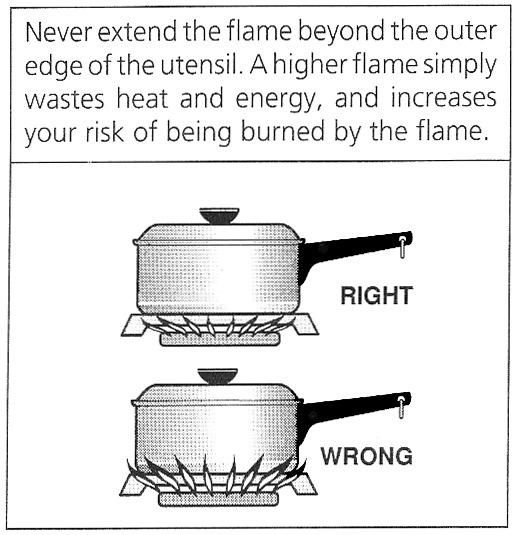
12 3) Do not obstruct the flow of combustion and ventilation air by blocking the room vents or air intakes. Restriction of air flow to the gas appliance prevents proper performance and increases carbon monoxide emission to unsafe levels. 4) Continuous use of the appliance may need extra ventilation, this can be solved by just opening a window or increasing exhaust power of a cooking hood. 5) If flame should go out during operation, turn the burner off. If a strong gas order is detected, open a window and wait five minutes before relighting the burner. 6) Be sure all control knobs are set in the OFF position prior to supplying gas to the range. COOKWARE To achieve optimum surface cooking performance, select heavy gauge, flat, smooth bottom pans that conform to the diameter of the cooking area as well as straight sides. Pan size should match the size of the cooking area. Pan should not extend more that 2 beyond the cooking area on gas cooking surface. Proper pans will reduce cooking times, use less energy and cook food more evenly. Remember to use pans with flat bottoms and handles that are easily grasped and stay cool. To minimize burns, ignition of flammable materials and spillage due to unintentional contact with the utensil, do not extend handles over adjacent surface burners. Always turn pan handles toward the side or back of the appliance, not out into the room where they are easily hit or reached by children. NOTES FOR COOKWARE ON GAS BURNERS We recommend the following pan size per each type of burner, fig. 08: BURNER TYPE COOKING PAN BOTTOM SIZE Power Med (14000 BTU) - on VEFSGGL/GEL65 from 6 to 8 in Ø Power Larg (17000 BTU) - on VEFSGGL/GEL65 from 8 to 12 in Ø U-Power (18500 BTU) - on VEFSGGL/GEL65 from 8 to 12 in Ø Burner operational Notes, fig. 08A: - A properly adjusted burner with clean ports will light within a few seconds. If using natural gas the flame will be blue with a deeper blue inner cone. - If the burner flame is yellow or is noisy the air/gas mixture maybe incorrect. Contact a service technician to adjust. - With LP gas, some yellow tips on the flames are acceptable. This is normal and adjustment is not necessary CU 36P VERONA PRO
13 - If soot is noticed on pan bottom, contact a service technician to adjust. - If the control knob is turned very quickly from HIGH to LOW, the flame may go out, particularly if the burner is cold. If this occurs, turn the knob to the OFF position, wait several seconds and relight the burner. Refer to LOW SETTING VALVE ADJUSTMENT chapter to adjust LOW setting, if needed. - The flame should not extend beyond the edge of the pan, fig. 08B. MAINTENANCE MOD: VEFSGGL65 - VEFSGEL65 CLEANING SAFETY Turn off all controls and wait for appliance parts to cool before touching or cleaning them. Do not touch the burner grates, oven inner surface or surrounding areas until they have had sufficient time to cool. Clean appliance with caution. Use care to avoid steam burns if a wet sponge or cloth is used to wipe spills on a hot surface. Some cleaners can produce noxious fumes if applied to a hot surface. RANGETOP GAS BURNERS Take off the removable parts and put them in soapy warm water for 10 minutes. Stubborn soils can be removed by using a nonabrasive pad or a plastic scouring pad, then rinse making sure that all openings are free of dirt, fig. 09. ATTENTION: After cleaning the burner cap, on top surface gas burners, make sure to place the burner cap in the right position, figure 10. SURFACE AND OVEN COOKING CAVITY CLEANING This is easily done using a damp cloth and a non-abrasive detergent, wipe using a soft dry cloth. For stainless steel parts with stubborn soils, use only plastic scrubbing pad or a sponge with vinegar and warm water. Because of many new cleaning products introduced in the marketplace each year, it is not possible to list all products that can be safely be used to clean this appliance. Read carefully the cleaner manufacturer s instructions to be sure the cleaner can be safely used on this appliance. Although, to determine if a cleaning product is safe, test a small inconspicuous area using a very light pressure to see if the surface may scratch or discolour. This is particularly important for porcelain enamel, highly polished, shiny, painted or plastic surfaces CU 36P VERONA PRO
14 ABNORMAL OPERATION Any of the following are considered to be abnormal operation and servicing is required. Do not use the appliance under these conditions: - Burner flame with yellow tips. - Soot on pan bottom. - Difficult burner ignition. - Burners fail to remain lit. - Burner will flame out. - Difficulty on turning gas valves. - Fan Red Light C on control panel lighted, it means Cooling Fan not working. See fig. Control Panel, page 31, VEFSGEL65S and VEFSGGL65S NOTES: Control regularly the correct functioning of Top Surface gas valves, oven gas thermostat and selector switch. In case of abnormal functioning of these devices, you must immediately call a qualified technical assistance service. OVEN DOOR MOD: VEFSGGL65 - VEFSGEL65 TO REMOVE OVEN DOOR 1) Fully open the oven door. 2) Insert a metal Locking Pin (B) in the Locking Hole (A) on each of the hinges, see figure 11. 3) Grasp the door by the sides toward the back. Raise the front of the door a few inches and make sure the Locking Pin (B) is locked by the door hinge. This will prevent the hinge from snapping closed when the door is removed. (There will be some spring resistance to overcome because of the hinge being locked). When the front of the door is high enough and hinges are locked, you will be able to lift the hinges to clear the slots 4) Pull the hinges out of the slots in the oven front frame. TO REPLACE THE OVEN DOOR 1) Grasp the sides of the door at the center and insert the ends of the hinges and fix hinge slots in the oven front frame. 2) With the door open all the way, pull-out the two Locking Pins (B) from the hinge Locking Holes(A). 3) Raise the oven door and make sure that it fits evenly with the front sides CU 36P VERONA PRO
15 WARNING: Never take out the Locking Pins while the door is off. Do not close the hinges without the weight of the door, the powerful springs will snap the hinges closed with great force. CAUTION: Do not place excessive weight on or stand on an open oven door. This could cause the range to tip over, break the door, or injure the user. Also, do not attempt to open or close door or operate oven until door is properly replaced. REPLACING THE OVEN LIGHT MOD: VEFSGGL65 - VEFSGEL65 WARNING: To prevent electrical shock and or personal injury: 1) Before replacing the light bulb, be sure the electric power is turned off at the circuit breaker. 2) Do not operate the oven unless the light cover is securely in position. 3) Be sure the oven and light bulb are cool. 4) Do not touch hot bulb with a damp cloth as this may cause the bulb to break. 5) If the light cover is damaged or broken, do not use the oven until a new cover is in place. To replace oven light bulb: 1) Before replacing light bulb, disconnect oven electric circuit. 2) Remove oven racks. 3) Remove, unscrewing, lens bulb cover and light bulb. 4) Replace bulb with a 25 W 120 Vac appliance bulb only. 5) Replace lens bulb cover. 6) Reconnect power to range. Reset electronic clock CU 36P VERONA PRO
16 INSTALLATION INSTRUCTIONS MOD: VEFSGGL65 - VEFSGEL65 SPECIAL WARNING: ONLY QUALIFIED AND AUTHORIZED PERSONNEL MUST INSTALL OR SERVICE THIS RANGE. READ SAFETY INSTRUCTIONS IN THIS BOOK BEFORE USING RANGE. IMPROPER INSTALLATION, ADJUSTMENT, ALTERATION, SERVICE, MAINTENANCE OR USE OF RANGE CAN RESULT IN SERIOUS INJURY OR PROPERTY DAMAGE, AND SO THE MANUFACTURER WILL NOT BE RESPONSIBLE. This appliance must be installed in accordance with the manufacturer s installation instructions and local codes or, in the absence of local codes, with the National Fuel Gas Code, ANSI Z223.1 / NFPA 54 in the U.S.A., and current CAN/CSA B149.1 Natural Gas and Propane Installation Code. CLEARANCE DIMENSIONS Range may be installed with zero inches clearance adjacent to (against) combustible construction at the rear and on the sides below the rangetop. For complete information in regard to the installation of wall cabinets above the range and clearances to combustible wall above the cooking top see the installation drawing fig. n 12 and 13. For Safety considerations do not install a range in any combustible cabinetry which is not in accord with the installation drawings. NOTE: 42 inch dimension between cooking top and wall cabinet shown on illustration fig. n 13 does not apply to ranges with an elevated oven. The A 42 inch dimension may be reduced to not less than 36 inches when the wall cabinets in a domestic home are protected with fireproof materials in accordance with American National Standards National Fuel Gas Code. B has to be not less than 8 inch from the top surface to a vertical side combustible wall. The C dimension is the total of product s width plus 1. To eliminate the risk of burns or fire by reaching over heated surface units, cabinet storage space located above the surface units should be avoided. If cabinet storage is to be provided, the risk can be reduced by installing a range hood that projects horizontally a minimum of 5 inches beyond the bottom of the cabinets CU 36P VERONA PRO
17 CAUTION: SOME CABINETS AND BUILDING MATERIALS ARE NOT DESIGNED TO WITHSTAND THE HEAT PRODUCED BY THE NORMAL SAFE OPERATION OF A LISTED APPLIANCE. DISCOLORATION OR DAMAGE, SUCH AS DELAMINATION, MAY OCCUR. LOCATING THE RANGE Do not set range over holes in the floor or other locations where it may be subject to strong drafts. Any opening in the wall behind the range and in the floor under the range should be sealed. Make sure the flow of combustion or ventilation air is not obstructed. NOTE: A range should not be installed over kitchen carpeting. VENTILATION Ventilation must be in accordance with local installation code. The appliance must be installed in a well-ventilated environment to guarantee a correct combustion gases exchange, proper air circulation and working temperature within safety limits. MODEL NUMBER PLATE The Model Number Plate is located in front oven surface, on right side. A second Model Number Plate is applied on the front page of the instruction booklet. ANTI-TIP DEVICE INSTALLATION INSTRUCTIONS MOD: VEFSGGL65 - VEFSGEL65 NOTE: A risk of range tip over exists if the appliance is not installed in accordance with the installation instructions provided. The proper use of this device minimises the risk of TIPPING-OVER. In using this device the consumer must still observe the safety precautions as stated in the Instruction Manual and avoid using the oven door and/or lower drawer as a step stool. Installation instructions are provided for wood and cement wall. Any other type of construction may require special installation techniques as deemed necessary to provide adequate fastening of the ANTI-TIP bracket to the wall. STEP 1 Locating The Bracket (see fig. 14) A. Mark the wall from either the right or left rear EDGE of the range is to be located. B. Place the Anti-Tip Bracket 8 5/8 from the marked EDGE toward centre of opening and against the back wall with a first hole height of 1 ¾ plus A (distance between side wall bottom edge and floor after range leveling) as shown in figure CU 36P VERONA PRO
18 C. Use the bracket as a template and mark the required holes, as shown in figure 14, for the type of construction you will be using. STEP 2 Anti-Tip Bracket Installation Locate the center of the two holes to be drilled on the wall. Drill a 1/8 pilot hole in the centre of each hole. (A nail or awl may be used if a drill is not available). On Wood Construction Wall secure the Anti-Tip bracket to the wall with the two 3/8 x 1 ½ self-drilling screws provided, and on Cement or Concrete Construction Wall secure the Anti-Tip bracket to the wall by drilling two holes with a 4/8 drilling bit and using the two 3/8 x 1 ½ wall plugs with screw. NOTE: Be aware of not drilling the wall hole in proximity of steel pipes or other components inside the wall that may be damaged. As shown in figure 14 you have two slots in the rear cover to choose from. Also, use a minimum of 2 screws to install bracket to the wall. STEP 3 Range Installation A. Align the range to its designated location and slide it back into position. Make sure that the Anti-Tip bracket plate is fully inserted into the range rear cover slot and above the lower frame plate. B. For Safety Considerations as well as optimum performance adjust the range so it is level. This may be checked by placing a spirit level or a large pan of water on the rangetop or on the oven rack. If an adjustment is required on free standing, pull the range forward, tip the range and rotate the levelling feet as required. Slide-in ranges require total removal from cabinet before an adjustment can be made. C. To check the range for proper installation of the anti-tip bracket: Remove lower name-tag cover or foot cover, by unscrewing its four fixing screws. Use a flashlight and look beneath lower frame plate and verify that the anti-tip device horizontal side is properly engaged in the rear cover slot and just above the lower frame plate. D. Proceed with the reminder of the installation instructions as well as proper range four legs installation, see please fig. 14A CU 36P VERONA PRO
19 CONNECTING THE RANGE MOD: VEFSGGL65 - VEFSGEL65 ELECTRICAL SUPPLY The appliance, when installed, must be electrically grounded in accordance with local codes or, in absence of local codes, with National Electrical Code, ANSI/NFPA 70 In Canada the appliance must be installed in accordance with the current CSA Standard C Canadian Electrical Code part 1. IMPORTANT: The appliance must only be installed by a qualified and specialized electrician. ELECTRICAL INSTALLATION FOR RANGE WITH GAS OVEN MOD: VEFSGGL65 This appliance is equipped with a three-prong grounding plug, which must be plugged directly into a properly grounded three-hole single-phase 120 VAC 60 Hz 15 amps electrical outlet. NOTE: House wiring and fusing must comply with local codes. If no local codes are applicable, wire in accordance with the National Electrical Code, ANSI/NFPA 70 latest edition. The three-prong grounding plug offers protection against shock hazards. DO NOT CUT OR REMOVE THE THIRD GROUNDING PRONG FROM THE POWER CORD PLUG. If an ungrounded, two-hole or other type of electrical outlet is encountered, it is the personal responsibility of the appliance owner to have the outlet replaced with a properly grounded three-hole electrical outlet. The cable cord connected to the appliance is a flexible type of cable. Pass it through hole prepare in cabinet to plug it to wall socket. To facilitate service, the flex cable must not be shortened and should be routed to permit temporary removal of the appliance. ELECTRICAL INSTALLATION FOR RANGE WITH ELECTRIC OVEN MOD: VEFSGEL65 The Range can be installed either with a double-phase 120/240V ~ 60 Hz for Canada and 120/208V ~ 60 Hz for US, use flexible cord type according with National Codes. CAUTION: Be sure the electrical power is off from the breaker box to the junction box until the range is installed and ready to operate CU 36P VERONA PRO
20 In case of a fixed connection to junction box, a 1/8 open gap two way switch must be used before the Junction Box. NOTE: Install a suitable flexible cord, through Junction Box on rear of appliance, to oven electrical terminal block. Follow fig. 15A and fig. 15B for proper electrical connection of flexible cord to appliance terminal block. Attention: always refer to product label for correct electrical power rate, before proceeding with electrical connection. ELECTRICAL CONNECTION ON TERMINAL BLOCK 1. For Double phase connection 120/240V~ 60 Hz for Canada, fig. 15A; On position n 1, connect the Black electrical supply wire (hot wire or L1), position n 2, connect the Red electrical supply wire (hot wire or L2), position n 3, connect the White electrical supply wire (neutral wire or N), to position, connect the Green ground electrical supply wire (ground wire or E) 2. For Double phase connection 120/208V~ 60 Hz for US, fig. 15B; On position n 1, connect the Black electrical supply wire (hot wire or L1), position n 2, connect the Red electrical supply wire (hot wire or L2), position n 3, connect the White electrical supply wire (neutral wire or N), to position, connect the Green ground electrical supply wire (ground wire or E) CAUTION: The flexible cord must be held tight by the cord lock, in such a way that it may not be pulled out. The flexible cord path must not be in proximity or in contact with hot surfaces that may damage the cord itself. GROUNDING IMPORTANT: Local codes might vary, installation, electrical connections and grounding must comply with all applicable local codes. WARNING: This appliance requires a ground connection for your protection against shock hazard and should be connected directly into a properly grounded receptacle CU 36P VERONA PRO
21 WARNING: DISCONNECT ELECTRICAL SUPPLY BEFORE SERVICING THE APPLIANCE. When the flexible cord has to be changed it is necessary to follow the procedure hereafter described: -Turn off main gas shut-off valve and disconnect electrical supply -Pull out entire range from the counter. -Disconnect gas supply connector from appliance gas manifold -Open up connecting terminal block cover. -Open flexible cord lock and loosen up old cord prongs from terminal block -Connect new flexible cord prongs to terminal block and fix flexible cord lock, remember earth wire, Green, must be longer by one inch that the other ones. For Line and Neutral wire connection, follow signs on terminal block. -The flexible cord must be held tight by the cord lock, in such a way that it may not pulled out. The flexible cord path must not be in proximity or in contact with hot surfaces that may damage the cord itself. ATTENTION: the flexible cord must be in accordance with National Electrical Codes and suitable for the Range technical characteristics electrical ratings. A 18 AWG three-prong grounding plug flexible cord, type SJT 3x18 AWG for the gas oven range only. Use a suitable prong grounding plug flexible cord, type SJT for the electric oven range according to the type of electrical system available. THE MANUFACTURER DECLINE ANY RESPONSIBILITY FOR IMPROPER INSTALLATION, ADJUSTMENT, ALTERATION, SERVICE, MAINTENANCE OR USE OF RANGE WHICH CAN RESULT IN SERIOUS INJURY OR PROPERTY DAMAGE. GAS SUPPLY MOD: VEFSGGL65 - VEFSGEL65 Installation of this range must conform with local codes or, in the absence of local codes, with the National Fuel Gas Code, ANSI Z223.1 latest edition. In Canada the range must be installed in accordance with the current CGA Standard CAN/CGA-B149 Installation Codes for Gas Burning Appliances and Equipment and/or local codes. GAS SUPPLY CONNECTION: (SEE FIGURE 17B) A TRAINED SERVICEMAN OR GAS APPLIANCE INSTALLER MUST MAKE THE GAS SUPPLY CONNECTION. Leak testing of the appliance shall be conducted by the installer according to the instructions given in section (h) CU 36P VERONA PRO
22 Natural gas supply line must have a natural service regulator. Inlet pressure to this appliance should be reduced to a maximum of 7 inches water column. Liquefied Petroleum L.P. / Propane gas supply line must have a L.P. gas pressure regulator. Inlet pressure to this appliance should be reduced to a maximum of 14 inches water column. Inlet pressure in excess of 14 in. W.C. can damage the appliance pressure regulator, or other gas components in this appliance and can result in a gas leak. a) A manual gas valve must be put in an accessible location in the supply line ahead of the appliance, for turning on and turning off gas supply. If hob is to be connected to house piping with flexible or semi-rigid metal connectors for gas appliances, connector nuts must not be connected directly to pipe threads. The connectors must be installed with adapters provided with the connector. b) The house piping and/or range connector used to connect the hob to the main gas supply must be clean, free of metal shavings rust, dirt and liquids (oil or water). Dirt, etc in the supply lines can work its way into the range manifold and in turn cause failure of the gas valves or controls and clog burners and/or pilot orifices. CAUTION: DO NOT LIFT OR MOVE RANGE BY DOOR HANDLES OR BACKGUARD. c) Turn off all pilots and main gas valve of other gas appliances. d) Turn off main gas valve at meter. e) Before connecting range apply pipe thread compound approved for LPG to all threads. f) Connect range to gas supply at appliance pressure regulator using adapters supplied with flexible connector. Rigid pipe may also be used. See rating plate for type of gas range has been manufactured for. g) Turn on main gas valve at meter, and relight pilots at other gas appliances. h) Apply a non-corrosive leak detection fluid to all joints and fittings in the gas connection between the supply line shut-off valve and the range. Include gas fittings and joints in the range if connections were disturbed during installation. Check for leaks! Bubbles appearing around fittings and connections will indicate a leak. If a leak appears, turn off supply line gas shut-off valve, tighten connections, turn on the supply line gas shut off valve, and retest for leaks CU 36P VERONA PRO
23 CAUTION: NEVER CHECK FOR LEAKS WITH A FLAME. WHEN LEAK CHECK IS COMPLETE, WIPE OFF ALL RESIDUE. i) Remove shipping polystyrene from ALL rangetop burners. This is to hold the burners in place on the burner base for shipping purposes only. This should be done last CHECKING PRESSURE OF HOUSE PIPING SYSTEM 1) The appliance and its individual shutoff valve must be disconnected from the gas supply piping system during any pressure testing of that system at test pressure in excess of ½ lbs./sq. in. (3.5 kpa or 13.8 in. water column). 2) The appliance must be isolated from the gas supply piping system by closing its individual manual shutoff valve during any pressure testing of the gas supply piping system at test pressure equal to or less than ½ lbs./sq. in. (3.5 kpa or 13.8 in. water column). GAS CONVERSION MOD: VEFSGGL65 - VEFSGEL65 NOTE: All gas adjustment must be done by a qualified service personnel only. All Ranges are equipped with both Natural Gas and LP Gas injectors as well as a convertible appliance pressure regulator. The unit model number plate states which gas it was adjusted for at the factory. To convert the unit to either Natural gas or LP gas will require switching burner injectors, the bypass screw (where necessary) and adjustment of the appliance pressure regulator converter cap. Inlet pressure to the appliance pressure regulator should be as follows for both operation and checking of appliance pressure regulator setting: INLET PRESSURE IN INCHES OF WATER COLUMN. PRESSURE Minimum Maximum Natural gas 4 7 LP gas GAS BURNER INJECTOR CONVERSION To switch injectors, it is enough to unscrew fixed injector using a proper 7 Hex. key tool and replace it with new injector for new gas setting. For proper injector size, follow the Technical Data chart (page 24) and fig CU 36P VERONA PRO
24 In case of yellow flame on oven gas burner (MOD: VEFSGGL65) as well as of distinct blue flame but lifting, call the technical assistance centre for further control and fix to solve the problem. APPLIANCE PRESSURE REGULATOR CONVERSION MOD: VEFSGGL65 - VEFSGEL65 NOTE: All gas adjustment must be done by a qualified service personnel only. The unit appliance pressure regulator must be set to match the type gas supply used. If converting from natural gas to LP gas, the appliance pressure regulator must be converted to regulate LP gas. If converting from LP gas to natural gas, the appliance pressure regulator must be converted to regulate natural gas. In case of replacement gas regulator you must use a CSA certified Pipe Sealant only To convert the appliance pressure regulator from one gas to another; remove the cap, push down and turn counter-clockwise. Turn the cap over and reinstall, follow the NAT or LP indication (figure 17A and 17B). NOTE: THE GAS TYPE YOU ARE CONVERTING TO MUST BE VISIBLE ON THE TOP OF THE INSTALLED APPLIANCE PRESSURE REGULATOR CAP. SERVICE PARTS INFORMATION MOD: VEFSGGL65 - VEFSGEL65 When your range requires service or replacement parts, contact your dealer or authorised service agency. Please give the complete model and serial number of the range which is located on the range model number plate. GAS VALVE BY-PASS CONVERSION NOTE: All gas adjustment must be done by a qualified service person only. To convert the rangetop: Remove all the knobs, remove the control panel. Using a small flat tip screwdriver switch the by-pass screws (figure 18A) with a new one if necessary, according to the technical data chart (page 24). The new by-pass screw must be totally closed. To convert the gas oven: Remove all the knobs, remove the control panel. Using a small flat tip screwdriver, find the by-pass screws (figure 18B). Turn right until the screw is completely closed. Then turn left the by-pass screw for a degrees indicated to Technical Data chart (page 24) CU 36P VERONA PRO
25 RANGETOP AND OVEN BURNER TECHNICAL DATA VEFSGE/GGL65 ISPH (NATURAL GAS) BURNER MAX POWER BTU/HR Injector Valve burner adjusting screw Natural HIGH SIMMER HIGH by-pass SIMMER by-pass U-POWER close 0.66 close POWER LAR close close POWER MED close 0.57 close OVEN open 230 BROIL / VEFSGE/GGL65 ISPH (LP GAS) BURNER MAX POWER BTU/HR Injector Valve burner adjusting screw PROPANE HIGH SIMMER HIGH by-pass SIMMER by-pass U-POWER close 0.48 close POWER LAR close 0.48 close POWER MED close 0.39 close OVEN open 90 BROIL / OVEN TECHNICAL DATA ELECTRICAL DATA VEFSGGL65 S CONVECTION GAS OVEN VEFSGEL65S CONVECTION ELECTRIC OVEN VOLTAGE 120 Vac 60 Hz 120/240/208 Vac 60Hz TOTAL POWER BTU 3000 W BROILING BURNER / ELEMENT BTU 1050 / 2500 W BOTTOM BURNER / ELEMENT BTU 2000 W OVEN LIGHT 2 x 25 W 2 x 25 W OVEN FAN 25 W 25 W COOLING FAN 30 W 30 W OVEN INTERIOR DIMENSIONS HEIGHT 12 1/2 in 14 in WIDTH 29 in 29 in DEPTH 16 in 16 in OVERALL SIZE 4.0 cu. ft. 4.0 cu. ft. OVEN ACCESSORIES Dripping Tray with Broil Rack 1 1 Cooking Racks, four rack positions 3 3 DIMENSIONS OF THE APPLIANCES Series Width (in) Height (in) Depth (in) VEFSGGL / ½ VEFSGEL / ½ In our continuing effort to improve the quality and performance of our cooking products, it may be necessary to make changes to the appliance without revising this guide. The manufacturer does not take any responsibility on booklet printing mistakes CU 36P VERONA PRO


26 FIGURES MOD: VEFSGGL65 - VEFSGEL65 MOD: VEFSGGL65 - VEFSGEL65 Fig. n 01 Fig. n 02 MOD: VEFSGGL65 Fig. n 03 MOD: VEFSGGL65 Fig. n 04 MOD: VEFSGGL65 MOD: VEFSGEL65 MOD: VEFSGEL65 Fig. n 05 Fig. n 06 Fig. n CU 36P VERONA PRO


27 Fig. n 08 Fig. n 09A Fig. n 09B Fig. n CU 36P VERONA PRO

28 Fig. n 11 Fig. n CU 36P VERONA PRO
29 Fig. n 13 One bracket either location Fig. n CU 36P VERONA PRO


30 Fig. 14A Fig. n 15A TERMINAL BLOCK CONNCTION FOR CANADA Fig. n 15B TERMINAL BLOCK CONNCTION FOR US 120/240V AC 60 Hz 120/208V AC 60 Hz MOD: VEFSGEL65 MOD: VEFSGEL65 MOD: VEFSGGL65 Fig. n 15C CU 36P VERONA PRO


31 Fig. n 16 Fig. n 18A MOD: VEFSGGL65 - VFSGEL65 Fig. n 17A Fig. n 18B MOD: VEFSGGL65 Fig. n 17B CU 36P VERONA PRO
32 CONTROL PANEL FEATURES Fig. n 19 Control Panel on range model: VEFSGEL65 Control Panel on range model: VEFSGGL CU 36P VERONA PRO

33 BACKGUARD FIXING PROCEDURE MOD: VEFSGGL65 - VEFSGEL65 First, Second, Third, Fourth, unpack Backguard from Range packaging. STEP 1: holding backguard in the upright position, insert slotted pin into the external cut, as shown in the figure. STEP 2: holding backguard in the upright position, slide it forward till the vertical back lower flange is touching the back surface of the cooktop. STEP 3: fix and secure backguard to cooktop with the three supplied auto-thread screws. And last, make sure backguard is in place and secured by moving back and forth the backguard itself CU 36P VERONA PRO
34 WIRING DIAGRAM FOR RANGE WITH GAS OVEN MOD: VEFSGGL65 WIRING DIAGRAM FOR RANGE WITH ELECTRIC OVEN MOD: VEFSGEL CU 36P VERONA PRO
IMPORTANT: SAVE THESE INSTRUCTIONS.
 FREE STANDING RANGE GAS AND ELECTRIC APPLIANCES EUROCHEF USA inc. MOD.: VEFSGG30SS MOD.: VEFSGG31SS INSTRUCTION GUIDE INSTALLATION AND MAINTENANCE IMPORTANT: SAVE THESE INSTRUCTIONS. IMPORTANT SAFETY INSTRUCTIONS
GAS WALL OVEN. Model: SGWO30SS OWNER S MANUAL. with INSTALLATION and MAINTENANCE INSTRUCTIONS
 GAS WALL OVEN Model: SGWO30SS OWNER S MANUAL with INSTALLATION and MAINTENANCE INSTRUCTIONS BEFORE USE, PLEASE READ AND FOLLOW ALL SAFETY RULES AND OPERATING INSTRUCTIONS. Write Serial Number here: FELIX
INSTALLER: LEAVE THESE INSTRUCTIONS WITH THE APPLIANCE INSTALLATION MANUAL. 'Gas 30-inch Wide Free-standingRange
 INSTALLER: LEAVE THESE INSTRUCTIONS WITH THE APPLIANCE INSTALLATION MANUAL 'Gas 30-inch Wide Free-standingRange PLEASE KEEP THIS MANUAL FOR FUTURE REFERENCE THE MANUAL IS INTENDED TO ASSIST IN THE INITIAL
Installation Instructions Dual Fuel Ranges
 Installation Instructions Dual Fuel Ranges E30DF74EPS E36DF76EPS E48DF76EPS 5995447082 2 Safety IMPORTANT SAFETY INSTRUCTIONS Safety Precautions Do not attempt to install or operate your unit until you
Owner s Guide Installation & Operation
 Owner s Guide Installation & Operation Hot Top HHT Series Hestan Commercial Corporation 3375 E. La Palma Ave Anaheim, CA 92806 (888) 905-7463 RETAIN THIS MANUAL FOR FUTURE REFERENCE P/N 002130 REV 1 IMPORTANT
DESIGN CLASS FUNCTION
 PROFESSIONAL QUALITY COOKING EQUIPMENT INSTALLATION MANUAL FOR MEDALLION DUAL FUEL RANGES MODEL NUMBERS: ARR-304DF, ARR-366DF, ARR-364GDDF, ARR-364GRDF, ARR-486GDDF, ARR-486GRDF, ARR-4822GDDF, ARR-484X2GRDF,
Gas Cooktop Installation, User and Service Instructions GMS 955.1
 Gas Cooktop Installation, User and Service Instructions GMS 955.1 IMPORTANT: SAVE FOR LOCAL ELECTRICAL INSPECTOR S USE. READ AND SAVE THESE INSTRUCTIONS FOR FUTURE REFERENCE. OBSERVE ALL FEDERAL, STATE
INSTALLATION GUIDE Dual Fuel Ranges
 INSTALLATION GUIDE Dual Fuel Ranges Contents Wolf Dual Fuel Ranges......................... 3 Safety Instructions............................ 4 Dual Fuel Range Specifications.................. 5 Dual Fuel
Owner s Guide Installation & Operation
 Owner s Guide Installation & Operation Char Broiler HCH Series Hestan Commercial Corporation 3375 E. La Palma Ave Anaheim, CA 92806 (888) 905-7463 RETAIN THIS MANUAL FOR FUTURE REFERENCE P/N 002134 REV
GAS COOKTOP INSTALLATION INSTRUCTIONS
 INSTALLATION AND SERVICE MUST BE PERFORMED BY A QUALIFIED INSTALLER. IMPORTANT: SAVE FOR LOCAL ELECTRICAL INSPECTOR'S USE. READ AND SAVE THESE INSTRUCTIONS FOR FUTURE REFERENCE. WARNING If the information
30" GAS RANGE INSTALLATION INSTRUCTIONS (For Models with Sealed Top Burners)
") INSTALLATION AND SERVICE MUST BE PERFORMED BY A QUALIFIED INSTALLER. IMPORTANT: SAVE FOR LOCAL ELECTRICAL INSPECTOR'S USE. READ AND SAVE THESE INSTRUCTIONS FOR FUTURE REFERENCE. If the information in this
INSTALLATION AND SERVICE MUST BE PERFORMED BY A QUALIFIED INSTALLER. IMPORTANT: SAVE FOR LOCAL ELECTRICAL INSPECTOR'S USE. READ AND SAVE THESE INSTRUCTIONS FOR FUTURE REFERENCE. If the information in this
INSTALLATION INSTRUCTIONS FOR FREESTANDING DUAL FUEL
 INSTALLATION AND SERVICE MUST BE PERFORMED BY A QUALIFIED INSTALLER. IMPORTANT: SAVE FOR LOCAL ELECTRICAL INSPECTOR'S USE. READ AND SAVE THESE INSTRUCTIONS FOR FUTURE REFERENCE. If the information in this
Multi-Function Cooktop
 INSTALLATION GUIDE Multi-Function Cooktop Contents Wolf Multi-Function Cooktop.................... 3 Multi-Function Cooktop Specifications............ 4 Multi-Function Cooktop Installation...............
Seaward Products. OWNER S MANUAL Installation Operation - Maintenance. Princess Gourmet Model 345. Built-in Electric Oven ELECTRIC WALL OVEN
 Seaward Products ELECTRIC WALL OVEN OWNER S MANUAL Installation Operation - Maintenance Princess Gourmet Model 345 Built-in Electric Oven IMPORTANT: Read all instructions before operating Oven. Save the
ELECTRIC RANGE USER INSTRUCTIONS
 ELECTRIC RANGE USER INSTRUCTIONS THANK YOU for purchasing this high-quality product. If you should experience a problem not covered in TROUBLESHOOTING, please contact the dealer from whom you purchased
Gourmet Freestanding Range Gas Cooktop Electric Oven
 Gourmet Freestanding Range Gas Cooktop Electric Oven User Manual & Installation Instructions IMPORTANT SAFETY INSTRUCTIONS Carefully read the important information regarding installation, safety and maintenance.
ULTRA-MAX GAS RADIANT CHARBROILER. ULTRA-MAX GAS LAVA ROCK CHARBROILER MODELS 8024CBB, 8036CBB, 8048CBB, 8060CBB, and 8072CBB
 Star Manufacturing International Inc. 10 Sunnen Drive St. Louis, MO 63143 Phone: (314) 678-6303 Fax: (314) 781-2714 Installation and Operating Instructions 2M-Z20327 Rev. A 10/05/15 ULTRA-MAX GAS RADIANT
GAS COOKTOP MODELS: CTG365D, CTG305D, CTG304D TO REDUCE THE RISK OF FIRE, ELECTRIC SHOCK, OR INJURY TO PERSONS, OBSERVE THE FOLLOWING
 By CNP INDUSTRIES, INC. P.O. Box 18645 Anaheim, Ca 92817 (877) 387-6721 INSTALLATION INSTRUCTIONS GAS COOKTOP MODELS: CTG365D, CTG305D, CTG304D IMPORTANT: Before beginning installation please read these
USE AND CARE MANUAL GAS COOKTOP MODELS: CTG304D, CTG305D, CTG365D
 USE AND CARE MANUAL GAS COOKTOP MODELS: CTG304D, CTG305D, CTG365D IMPORTANT: Before beginning use please read these instructions completely and carefully. INSTALLER: Leave this owner s manual with the
NOTE: THIS APPLIANCE MUST BE INSTALLED SOLELY AND EXCLUSIVELY BY A QUALIFIED TECHNICIAN.
 Table of Contents 1. IMPORTANT SAFETY INSTRUCTIONS... 4 2. DESCRIPTION OF CONTROLS... 6 3. USING THE COOKTOP... 7 3.1 Ignition with safety device... 7 3.2 Practical advices to use the burners... 8 3.3
GAS COOKTOP INSTALLATION INSTRUCTIONS BEFORE YOU BEGIN. IMPORTANT Save these instructions for local electrical inspector s use.
 GAS COOKTOP INSTALLATION INSTRUCTIONS Please read this guide thoroughly before installation. To contact LG Electronics, 24 hours a day, 7 days a week: 1-800-243-0000 (U.S.A.) 1-888-542-2623 (Canada) Or
DESIGN CLASS FUNCTION
 PROFESSIONAL QUALITY COOKING EQUIPMENT INSTALLATION MANUAL FOR PERFORMER SLIDE-IN COOK TOPS MODEL NUMBERS: AROBSCT-424, AROBSCT-242GD, AROBSCT-24X2GR, AROBSCT-430, AROBSCT-636, AROBSCT-436GD, AROBSCT-436GR,
COOKTOP USER MANUAL & INSTALLATION INSTRUCTIONS
 COOKTOP USER MANUAL & INSTALLATION INSTRUCTIONS ANCONA ELITE 30 & 34 GAS COOKTOPS IMPORTANT SAFETY INSTRUCTIONS Carefully read the following important information regarding installation safety and maintenance.
Viking Installation Guide
 Viking Installation Guide Viking Range Corporation Front Street Greenwood, Mississippi 38930 USA (66) 455-00 For product information, visit the Viking Web site at vikingrange.com Professional Built-In
INSTALLATION AND OPERATION MANUAL GAS SKILLETS MODELS: GTS-30 GTS-40
 INSTALLATION AND OPERATION MANUAL GAS SKILLETS MODELS: GTS-30 GTS-40 CROWN FOOD SERVICE EQUIPMENT LTD. 70 OAKDALE ROAD, DOWNSVIEW, (TORONTO), ONTARIO, CANADA, M3N 1V9 TELEPHONE: (416) 746-2358, FAX: (416)
BUILT-IN OVEN MODEL: EBO-E7081D(SS) Owner s Manual Please read this manual carefully before operating your set. Retain it for future reference.
 Owner s Manual Please read this manual carefully before operating your set. Retain it for future reference.") BUILT-IN OVEN MODEL: EBO-E7081D(SS) Owner s Manual Please read this manual carefully before operating your set. Retain it for future reference. Record model number and serial number of the set. See the
BUILT-IN OVEN MODEL: EBO-E7081D(SS) Owner s Manual Please read this manual carefully before operating your set. Retain it for future reference. Record model number and serial number of the set. See the
INSTALLATION MANUAL. Rangetops. RNB Heritage Classic Platinum
 INSTALLATION MANUAL Rangetops RNB Heritage Classic Platinum 1 BLUESTAR INSTALLATION INSTRUCTIONS FOR RANGETOPS MODELS RNB, Heritage Classic, Platinum THIS APPLIANCE WAS DESIGNED FOR EASE OF INSTALLATION
IMPORTANT SAFETY INSTRUCTIONS
 INSTALLATION AND SERVICE MUST BE PERFORMED BY A QUALIFIED INSTALLER. IMPORTANT: SAVE FOR LOCAL ELECTRICAL INSPECTOR'S USE. READ AND SAVE THESE INSTRUCTIONS FOR FUTURE REFERENCE. for applicable agency certifications
Viking Installation Guide
 Viking Installation Guide Viking Range Corporation 111 Front Street Greenwood, Mississippi 38930 USA (662) 455-1200 For product information, call 1-888-VIKING1 (845-4641) or visit the Viking web site at
USER MANUAL Gas Countertop Charbroilers
 Gas Countertop Charbroilers REVISED 2/209 382799 LAVA BRIQUETTE MODELS: 35CLCPG5NL, 35CLCPG24NL, 35CLCPG36NL, 35CLCPG48NL, 35CLCPG60NL, 35CLCPG72NL Congratulations on your purchase of Cooking Performance
Installation Guide. 5 Series VGC and VGSU Built-In Gas Cooktops
 Installation Guide 5 Series VGC and VGSU Built-In Gas Cooktops Table of Contents Warnings & Important Safety Instructions 3 Dimensions VGC Cooktops 6 Specifications VGC Cooktops 7 Dimensions VGSU Cooktops
Installation / Assembly
 Cabinet Cut-out Dimensions...4 Gas Requirements and Connection...5 Leak Testing Procedure....6 LP Gas...7 Natural Gas...9 Installing Side Burner with a Grill...10 Save these instructions! Copyright 2009-2010
STAR-MAX GAS GRIDDLES MODELS 615MA 624MA 636MA 648MA 615TA 624TA 636TA 648TA 624TSPA 636TSPA 648TSPA
 Star Manufacturing International Inc. 10 Sunnen Drive St. Louis, MO 63143 Phone: (314) 781-2777 Fax: (314) 781-3636 Installation and Operating Instructions 2M-Z1351 Rev. B 4/23/04 STAR-MAX GAS GRIDDLES
OPERATING INSTRUCTIONS AND OWNER S MANUAL
 OPERATING INSTRUCTIONS AND OWNER S MANUAL MR. HEATER READ INSTRUCTIONS CAREFULLY: Read and follow all instructions. Place instructions in a safe place for future reference. Do not allow anyone who has
Installation Instructions
 WARNING! INSTALLATION SAFETY INSTRUCTIONS Read these instructions completely and carefully. Improper installation, adjustment, alteration, service or maintenance can cause injury or property damage. Refer
BUILT-IN OVEN MODEL: EBO-D7080D(SS) Owner s Manual Please read this manual carefully before operating your set. Retain it for future reference.
 Owner s Manual Please read this manual carefully before operating your set. Retain it for future reference.") BUILT-IN OVEN MODEL: EBO-D7080D(SS) Owner s Manual Please read this manual carefully before operating your set. Retain it for future reference. Record model number and serial number of the set. See the
BUILT-IN OVEN MODEL: EBO-D7080D(SS) Owner s Manual Please read this manual carefully before operating your set. Retain it for future reference. Record model number and serial number of the set. See the
LP GAS PIZZA OVEN USER MANUAL
 LP GAS PIZZA OVEN USER MANUAL To reduce the risk of fire, burn hazard or other injury, read the USER MANUAL carefully and completely before using this appliance FOR OUTDOOR USE ONLY Before Cleaning, make
Installation Instructions for Models: HES232U, HES236UHES246U, HES247U, HES245U, HES242U, HES256U, HES255U, HES252U
 Freestanding Electric Range Household Appliances 2U Installation Instructions for Models: HES232U, HES236UHES246U, HES247U, HES245U, HES242U, HES256U, HES255U, HES252U PLEASE READ ENTIRE INSTRUCTIONS BEFORE
GAS COOKER GAS OVEN SERIES. Owner s Manual Please read this manual carefully before operating your set. Retain it for future reference.
 GAS COOKER GAS OVEN SERIES Owner s Manual Please read this manual carefully before operating your set. Retain it for future reference. Record model number and serial number of the set. See the label attached
INSTALLATION & OPERATION MANUAL GAS CHARBROILERS
 INSTALLATION & OPERATION MANUAL GAS CHARBROILERS MODELS VCCB25 VCCB36 VCCB47 VCCB60 VCCB72 VCCB47 SCB25 SCB36 SCB47 SCB60 SCB72 SCB47 ITW Food Equipment Group, LLC 3600 North Point Blvd. Baltimore, MD
V SERIES HDR GAS RANGES
 SERVICE MANUAL ONE POWERFUL PACKAGE V SERIES HDR GAS RANGES TOPS Open Top Hot Top Griddle Top Work Surface BASES Standard Oven Convection Oven Cabinet Base - NOTICE - This manual is prepared for use by
GPC PASTA PRO INSTALLATION & USER OPERATION MANUAL
 GPC-14/18/20 GPC PASTA PRO INSTALLATION & USER OPERATION MANUAL GPC-18 shown with optional rinse station. NOTICE! After installation of your equipment, immediately contact your local gas supplier to obtain
Viking Installation Guide
 Viking Installation Guide Viking Range Corporation Front Street Greenwood, Mississippi 38930 USA (66) 455-00 For product information, call -888-VIKING (845-464) or visit the Viking Web site at vikingrange.com
Viking Installation Guide
 Viking Installation Guide Viking Range Corporation 111 Front Street Greenwood, Mississippi 38930 USA (662) 455-1200 For product information, call 1-888-VIKING1 (845-4641) or visit the Viking Web site at
TRI-STAR INC SOUTH STANDARD AVENUE, SANTA ANA, CA Ph: Fax: MODEL #. OWNER S MANUAL
 TRI-STAR INC 2205 SOUTH STANDARD AVENUE, SANTA ANA, CA 92707 Ph: 714 424 9380 Fax: 714 424 9385 MODEL #. OWNER S MANUAL INSTALLATION OPERATION MAINTENANCE All equipments manufactured by Tri-star Inc. for
READ AND SAVE THESE INSTRUCTIONS
 READ AND SAVE THESE INSTRUCTIONS WARNING TO REDUCE THE RISK OF FIRE, ELECTRIC SHOCK, OR INJURY TO PERSONS, OBSERVE THE FOLLOWING: 1. Use this unit only in the manner intended by the manufacturer. If you
INSTALLATION INSTRUCTIONS
 INSTALLATION INSTRUCTIONS VGSU SERIES BUILT-IN GAS COOKTOPS VIKING RANGE CORPORATION 111 Front Street Greenwood, Mississippi 38930 USA (662) 455-1200 IMPORTANT: PLEASE READ AND FOLLOW 1. Before beginning,
CYLINDER NOT INCLUDED
 OPERATING INSTRUCTIONS AND OWNER S MANUAL Model # HS125NG / MH125LP / HS125LP READ INSTRUCTIONS CAREFULLY: Read and follow all instructions. Place instructions in a safe place for future reference. Do
Owner s Guide Installation & Operation
 Owner s Guide Installation & Operation Fryer HFR Series Hestan Commercial Corporation 3375 E. La Palma Ave Anaheim, CA 92806 (888) 905-7463 RETAIN THIS MANUAL FOR FUTURE REFERENCE P/N 002137 REV 1 IMPORTANT
PRO SERIES GAS FRYERS OWNER S MANUAL
 PRO SERIES GAS FRYERS OWNER S MANUAL MODELS: PF-1 PRO-FRYER, PF2 DUAL PRO-FRYER REVISED OCTOBER, 2009 *PLEASE RETAIN FOR FUTURE REFERENCE This appliance has been tested according to ANSI Z83.116-2009/CSA1.86-2009.
LRG. Professional Gas Range User Manual
 LRG Professional Gas Range User Manual Thank you for purchasing your LRG indoor range. We appreciate your business and we recommend that you read the entire User s Manual before operating your new appliance
Use & Care. Gas Range. All about the. of your TABLE OF CONTENTS
 All about the Use & Care of your Gas Range TABLE OF CONTENTS Product Record and Registration.............. 2 Important Safety Instructions................. 3 Before Setting Surface Controls...............
Owner s Manual GEMINI PETIT CHEF MULTIFUNCTION THERMOFAN
 Owner s Manual GEMINI PETIT CHEF MULTIFUNCTION THERMOFAN EYE LEVEL OVEN CONTENTS 2 Introduction 2 Unpacking 2 Cupboard Design 2 Safety Advice 3 Installation 3 Electrical Installation 4 The Control Panel
INSTALLATION MANUAL. Double Electric Wall Oven
 INSTALLATION MANUAL Double Electric Wall Oven 799258 BLUESTAR INSTALLATION INSTRUCTIONS FOR THE RESIDENTIAL ALL ELECTRIC WALL OVEN FOR THE HOME MODELS DEWO THIS APPLIANCE WAS DESIGNED FOR EASE OF INSTALLATION
Installation Instructions Dual Fuel Ranges
 Installation Instructions Dual Fuel Ranges E30DF74EPS E36DF76EPS E48DF76EPS 5995447082 2 Safety IMPORTANT SAFETY INSTRUCTIONS Safety Precautions Do not attempt to install or operate your unit until you
30" ELECTRIC SLIDE-IN RANGE INSTALLATION INSTRUCTIONS
 United States INSTALLATION AND SERVICE MUST BE PERFORMED BY A QUALIFIED INSTALLER. IMPORTANT: SAVE FOR LOCAL ELECTRICAL INSPECTOR'S USE. READ AND SAVE THESE INSTRUCTIONS FOR FUTURE REFERENCE. FOR YOUR
STAR-MAX PROPANE GAS GRIDDLE
 Star Manufacturing International Inc. 10 Sunnen Drive St. Louis, MO 63143 Phone: (314) 781-2777 Fax: (314) 781-3636 Installation and Operating Instructions 2M-Z3793 Rev. B 3/28/03 STAR-MAX PROPANE GAS
INSTALLATION & OPERATING INSTRUCTIONS
 INSTALLATION & OPERATING INSTRUCTIONS MODEL #85747 WARMING DRAWER MANUAL TABLE OF CONTENTS PAGE # SAFETY INSTRUCTIONS.........2 INSTALLATION INSTRUCTIONS......................3 ISLAND INSTALLATION...3
INSTRUCTION MANUAL. for 2-Burner Cook Top. Model B41602
 Page 1 INSTRUCTION MANUAL for 2-Burner Cook Top Model B41602 Felix Storch, Inc. Summit Appliance Division 770 Garrison Avenue Bronx, NY 10474 www.summitappliance.com Page 2 Please read these instructions
INSTALLER: LEAVE THESE INSTRUCTIONS WITH THE APPLIANCE INSTALLATION MANUAL. Dual Fuel 30-inch Wide Free-StandingRange
 INSTALLER: LEAVE THESE INSTRUCTIONS WITH THE APPLIANCE INSTALLATION MANUAL Dual Fuel 30-inch Wide Free-StandingRange PLEASE KEEP THIS MANUAL FOR FUTURE REFERENCE THE MANUAL IS INTENDED TO ASSIST IN THE
Instruction Manual for Electric Ovens OO757X OO986X
 Instruction Manual for Electric Ovens OO757X OO986X 1 2 DEAR CUSTOMER, We thank you and congratulate you on your choice. This new carefully designed product, manufactured with the highest quality materials,
Operating and Installation Instructions
 Operating and Installation Instructions Gas Cooktop KM 391 To prevent accidents and machine damage, read the Operating Manual before installation or use. UV M.-Nr. 06 073 600 WARNING: If the information
UNDER CABINET RANGE HOOD
 UNDER CABINET RANGE HOOD MANUAL IMPORTANT SAFETY INSTRUCTIONS READ AND SAVE THESE INSTRUCTIONS FOR DOMESTIC COOKING ONLY 1. Read all instructions before using the appliance 2. Install or locate this appliance
Installation Instructions
 Installation Instructions 30" Freestanding Gas Range with standard clean oven Tip Over Hazard A child or adult can tip the range and be killed. Connect anti-tip bracket to rear range foot. Reconnect the
Owner s Guide. 24-inch Gas Wall Oven with Time-Of-Day Clock and Timer Canada w A/01/08
 Owner s Guide 24-inch Gas Wall Oven with Time-Of-Day Clock and Timer TABLE OF CONTENTS IMPORTANT SAFETY INSTRUCTIONS... 2-4 MAINTENANCE... 11... Oven or broiler door... 11 CLOCK AND TIMER... 5 Oven bottom...
Using it in an enclosed space can kill you.
 38 X 56 GAS FIRE PIT - OWNER S MANUAL Carlisle Chat Fire Table Base Model # 00GBC7 (6877B) Fits 6877A Carlisle Chat Fire Table Top For Propane and *Natural Gas (*See Page 7) Certified to CSA International
Models KECS161 KECS Table of Contents...2
 ELECTRIC COOKTOP Use & Care Guide For questions about features, operation/performance, parts accessories or service, call: 1-800-422-1230 or visit our website at... www.kitchenaid.com. Table of Contents...2
Use, Care, and Installation Guide
 Use, Care, and Installation Guide Model PSU-E30AS XP022421(1) 182766 Safety Notice... 2-3 List of Materials... 4 D ucting Calculation Sheet... 5 Mounting Height & Clearance... 6 Ducting Options... 7 Hood
Installation GUIDE 6 SERIES. Built-in Electric Single and Double Wall Ovens MVSOE630 / CMVSOE630 MVDOE630 / CMVDOE630
 Installation GUIDE 6 SERIES Built-in Electric Single and Double Wall Ovens MVSOE630 / CMVSOE630 MVDOE630 / CMVDOE630 1 Table of Contents Warnings & Important Safety Information 2 Dimensions 4 Specifications
Operating Instructions for the KM 410 Electric Grill
 Operating Instructions for the KM 410 Electric Grill To prevent accidents and machine damage, ]ö read the Operating Manual before installation or use. M.-Nr. 05 060 910 Contents Contents Description of
VK902 Compact Combination Microwave Oven Installation, Use and Maintenance
 VK902 Compact Combination Microwave Oven Installation, Use and Maintenance Customer Care Department The Group Ltd. Harby Road Langar Nottinghamshire NG13 9HY T : 01949 862 012 F : 01949 862 003 E : customer.care@cda.eu
MHG201 Gas Hob Manual for Installation, Use and Maintenance
 MHG201 Gas Hob Manual for Installation, Use and Maintenance 1 Customer Care Department The Group Ltd. Harby Road Langar Nottinghamshire NG13 9HY T : 01949 862 012 F : 01949 862 003 E : customer.care@cda.eu
DESIGN CLASS FUNCTION
 PROFESSIONAL QUALITY COOKING EQUIPMENT INSTALLATION MANUAL FOR LEGACY BUILT-IN ELECTRIC,GAS AND HYBRID SINGLE AND DOUBLE WALL OVENS MODEL NUMBERS: GAS MODELS: AROFG-30, AROSG-30, AROFFG-230, AROSSG-230,
HVG620 & HVG720 Gas Hob Manual for Installation, Use and Maintenance
 HVG620 & HVG720 Gas Hob Manual for Installation, Use and Maintenance Customer Care Department The Group Ltd. Harby Road Langar Nottinghamshire NG13 9HY T : 01949 862 012 F : 01949 862 003 E : customer
PROF. RANGE COOKER MODEL: EPRC-A6456GE(SS) Owner s Manual Please read this manual carefully before operating your set. Retain it for future reference.
 Owner s Manual Please read this manual carefully before operating your set. Retain it for future reference.") PROF. RANGE COOKER MODEL: EPRC-A6456GE(SS) Owner s Manual Please read this manual carefully before operating your set. Retain it for future reference. Record model number and serial number of the set.
PROF. RANGE COOKER MODEL: EPRC-A6456GE(SS) Owner s Manual Please read this manual carefully before operating your set. Retain it for future reference. Record model number and serial number of the set.
Installation. Freestanding 30 Gas Self-Clean Sealed Burner Range
 Installation Viking Range Corporation Front Street Greenwood, Mississippi 890 USA (66) 455-00 For product information, call -888-VIKING (845-464) or visit the Viking Website at vikingrange.com Freestanding
Installation Requirements for Models:
 900 & 9100 Series Refrigerators Installation Requirements for Models: 9162 9163 9182 9183 962 963 982 983 WARNING Improper installation, adjustment, alteration, service, or maintenance can cause injury
GE Monogram. Installation. Instructions. Professional Ranges. 48" Natural Gas Models ZDP48N4GWSS ZDP48N6RWSS ZDP48N6DWSS
 GE Monogram Installation Instructions Professional Ranges 48" Natural Gas Models ZDP48N4GWSS ZDP48N6RWSS ZDP48N6DWSS 48" LP Gas Models ZDP48L4GWSS ZDP48L6RWSS ZDP48L6DWSS 36" Natural Gas Models ZDP36N6WSS
Installation Guide. 5 Series Professional Built-In Electric Single and Double Ovens 7 Series Professional Built-in Electric Double French Door Oven
 Installation Guide 5 Series Professional Built-In Electric Single and Double Ovens 7 Series Professional Built-in Electric Double French Door Oven Table of Contents Warnings & Important Safety Instructions
User s Manual WS-69TB30 / WS-69TB36 (22 ) WS-69TB42 / WS-69TB48 (22 ) WS-69TS30 / WS-69TS36 (18 ) WS-69TS42 / WS-69TS48 (18 )
 WS-69TB42 / WS-69TB48 (22 ) WS-69TS30 / WS-69TS36 (18 ) WS-69TS42 / WS-69TS48 (18 )") www.windsterhood.com User s Manual LINER SERIES WS-69TB30 / WS-69TB36 (22 ) WS-69TB42 / WS-69TB48 (22 ) WS-69TS30 / WS-69TS36 (18 ) WS-69TS42 / WS-69TS48 (18 ) NOTE: PLEASE INSPECT HOOD IMMEDIATELY UPON
www.windsterhood.com User s Manual LINER SERIES WS-69TB30 / WS-69TB36 (22 ) WS-69TB42 / WS-69TB48 (22 ) WS-69TS30 / WS-69TS36 (18 ) WS-69TS42 / WS-69TS48 (18 ) NOTE: PLEASE INSPECT HOOD IMMEDIATELY UPON
OPERATING INSTRUCTIONS MANUAL (Please retain for future reference) F-1000T DUAL FUEL CONSTRUCTION HEATER
 F-1000T DUAL FUEL CONSTRUCTION HEATER") OPERATING INSTRUCTIONS MANUAL (Please retain for future reference) For F-1000T DUAL FUEL CONSTRUCTION HEATER CERTIFIED FOR USE IN CANADA AND U.S.A. As per Standard ANSI Z83.7 2000/ CSA 2.14 2000 Gas Fired
OPERATING INSTRUCTIONS MANUAL (Please retain for future reference) For F-1000T DUAL FUEL CONSTRUCTION HEATER CERTIFIED FOR USE IN CANADA AND U.S.A. As per Standard ANSI Z83.7 2000/ CSA 2.14 2000 Gas Fired
Natural Gas Conversion Instruction for
 WARNING For Outdoor Use Only (outside any enclosure) Natural Gas Conversion Instruction for OUTDOOR 4-BURNER STAINLESS STEEL ISLAND GRILL WARNING. Improper installation, adjustment, alteration, service
INSTALLATION, OPERATION & MAINTENANCE AVANTCO SERIES 177AG OWNER S MANUAL
 INSTALLATION, OPERATION & MAINTENANCE AVANTCO SERIES 177AG OWNER S MANUAL Manual Griddles: Radiant Charbroilers: Hot Plates: 177AG24MG 177AG36MG 177AG24RC 177AG36RC 177AGR212 All equipment manufactured
OPERATING INSTRUCTIONS MANUAL (Please retain for future reference) F-400T DUAL FUEL CONSTRUCTION HEATER
 F-400T DUAL FUEL CONSTRUCTION HEATER") OPERATING INSTRUCTIONS MANUAL (Please retain for future reference) For F-400T DUAL FUEL CONSTRUCTION HEATER CERTIFIED FOR USE IN CANADA AND U.S.A. As per Standard ANSI Z83.7 2000/ CSA 2.14 2000 Gas Fired
OPERATING INSTRUCTIONS MANUAL (Please retain for future reference) For F-400T DUAL FUEL CONSTRUCTION HEATER CERTIFIED FOR USE IN CANADA AND U.S.A. As per Standard ANSI Z83.7 2000/ CSA 2.14 2000 Gas Fired
Viking Installation Guide
 Viking Installation Guide Viking Range, LLC Front Street Greenwood, Mississippi 890 USA (66) 55-00 For product information, call -888-85-6 or visit the Viking Web site at vikingrange.com Professional Freestanding
Service Manual For model N260 - a 2.4 cu. ft., 2-way refrigerator. For model N a 2.4 cu. ft., 3-way refrigerator.
 Service Manual For model N260 - a 2.4 cu. ft., 2-way refrigerator. For model N260.3 - a 2.4 cu. ft., 3-way refrigerator. NORCOLD, Inc. P.O. Box 4248 Sidney, OH 45365-4248 Part No. 619260A (4-98) Table
Use & Care. All about the. of your Wall Oven TABLE OF CONTENTS. Major Appliance Warranty...24
 All about the Use & Care of your Wall Oven TABLE OF CONTENTS Welcome & Congratulations...2 Setting Oven Controls - Model A...9 Important Safety Instructions...3 Setting Oven Controls - Model B...11 Features
D UAL F UEL R ANGES INSTALLATION INSTRUCTIONS
 D UAL F UEL R ANGES INSTALLATION INSTRUCTIONS As you follow these instructions, you will notice WARNING and CAUTION symbols. This blocked information is important for the safe and efficient installation
Use & Care Guide 36 Gas Range
 Use & Care Guide 36 Gas Range 318 203 967 (1006) Rev. A 2 Finding Information Make a Record for Future use Brand Purchase Date Model Number Serial Number Note The serial and model numbers may be found
INSTALLATION MANUAL. Free Standing Ranges. RCS (Open/Sealed) RNB RPB Platinum Precious Metals 1
 RNB RPB Platinum Precious Metals 1") INSTALLATION MANUAL Free Standing Ranges RCS (Open/Sealed) RNB RPB Platinum Precious Metals 1 750163 BlueStar Free Standing Range Installation Manual MODELS RCS, RPB, RNB, Platinum, Precious Metals THIS
INSTALLATION MANUAL Free Standing Ranges RCS (Open/Sealed) RNB RPB Platinum Precious Metals 1 750163 BlueStar Free Standing Range Installation Manual MODELS RCS, RPB, RNB, Platinum, Precious Metals THIS
Stone Hearth Pizza Dome Oven
 Stone Hearth Pizza Dome Oven INSTALLATION AND OPERATION MANUAL GAS-FIRED OVEN CAUTION This oven MUST be seasoned before initial use The seasoning procedure takes 6 days, running the oven for at least 8
INSTRUCTION MANUAL for Ceramic Glass Electric Cooktop Models CR1115 CR2110 CR2220 CR3240
 INSTRUCTION MANUAL for Ceramic Glass Electric Cooktop Models CR1115 CR2110 CR2220 CR3240 Please read these instructions in their entirety before installation and use of your cooktop. SAVE THIS MANUAL FOR
Installation Instructions
 Installation Instructions Gas & Electric Dryer Before beginning installation, carefully read these instructions. This will simplify the installation and ensure the dryer is installed correctly and safely.
GAS STAINLESS COOKTOPS
 GAS STAINLESS COOKTOPS CG604D & CG905D models CG604DCG905D USER GUIDE HK SG Contents 1 EN Safety and warnings 2 Introduction 5 Using your cooktop 6 Cooking guidelines and cookware 8 Care and cleaning
UNDER CABINET RANGE HOOD. This manual is made with 100 % recycled paper.
 UNDER CABINET RANGE HOOD This manual is made with 100 % recycled paper. IMPORTANT SAFETY INSTRUCTIONS READ AND SAVE THESE INSTRUCTIONS FOR DOMESTIC COOKING ONLY 1. Read all instructions before using the
IMPORTANT SAFETY INSTRUCTIONS Carefully read the following Important information redarding installation safety and maintenance.
 IMPORTANT SAFETY INSTRUCTIONS Carefully read the following Important information redarding installation safety and maintenance. Keep these instruction for future reference. USERS OPERATING INSTRUCTIONS
Some models are supplied with a protective film on steel and aluminium parts. This film must be removed before installing/using the appliance.
 ELECTRIC RANGE for residential use only R Models: VEFSEE365D.. INSTALLATION INSTRUCTIONS IMPORTANT - PLEASE READ AND FOLLOW Before beginning, please read these instructions completely and carefully. Do
Welcome & Congratulations
 Welcome & Congratulations Questions? 1-800-944-9044 (United States) 1-866-729-5199 (Canada) Please attach sales receipt here for future reference. Congratulations on your purchase of a new range! At Electrolux
BSM60SS / BSM60WH BUILT IN MULTI-FUNCTION ELECTRIC FAN OVEN. Instruction Manual
 BSM60SS / BSM60WH BUILT IN MULTI-FUNCTION ELECTRIC FAN OVEN Instruction Manual Please read these instructions carefully before use and retain for future reference CONTENTS Safety Instructions 2 Specifications
Owner s Manual STOVES. MODELS 620 Kitchenaire. 621 Kitchenaire 711S
 Owner s Manual STOVES MODELS 620 Kitchenaire 621 Kitchenaire 711S CONTENTS 2 Introduction 2 Unpacking 2 Installation 2 Electrical Installation 3 Safety Advice 3 Control Panels 4 The Oven 5 Solid Plates