Multistage Ejector MODEL / Series / Product Number
|
|
|
- Polly Daniels
- 5 years ago
- Views:
Transcription
1 Doc. no. ZL-0M00801 PRODUCT NAME Multistage Ejector MODEL / Series / Product Number ZL Series
2 Contents Doc. no. ZL-OM00801 Safety Instructions 2 Model Indication and How to Order 10 Mounting and Installation 12 Air Supply 12 Supply Pressure 13 Piping 13 Solenoid Valve 15 Construction 15 Maintenance and Inspection 17 Exhaust from Ejector 19 Specifications 19 Circuit Diagram 22 Weight 23 Exhaust Characteristics and Flow Characteristics of Ejector 24 Flow Characteristics Curves 25 Vacuum Pressure Switch Assembly 26 Troubleshooting
3 Safety Instructions These safety instructions are intended to prevent hazardous situations and/or equipment damage. These instructions indicate the level of potential hazard with the labels of Caution, Warning or Danger. They are all important notes for safety and must be followed in addition to International Standards (ISO/IEC) 1), and other safety regulations. 1) ISO 4414: Pneumatic fluid power -- General rules relating to systems. ISO 4413: Hydraulic fluid power -- General rules relating to systems. IEC : Safety of machinery -- Electrical equipment of machines.(part 1: General requirements) ISO : Manipulating industrial robots -Safety. etc. Caution Warning Danger Caution indicates a hazard with a low level of risk which, if not avoided, could result in minor or moderate injury. Warning indicates a hazard with a medium level of risk which, if not avoided, could result in death or serious injury. Danger indicates a hazard with a high level of risk which, if not avoided, will result in death or serious injury. Warning 1. The compatibility of the product is the responsibility of the person who designs the equipment or decides its specifications. Since the product specified here is used under various operating conditions, its compatibility with specific equipment must be decided by the person who designs the equipment or decides its specifications based on necessary analysis and test results. The expected performance and safety assurance of the equipment will be the responsibility of the person who has determined its compatibility with the product. This person should also continuously review all specifications of the product referring to its latest catalog information, with a view to giving due consideration to any possibility of equipment failure when configuring the equipment. 2. Only personnel with appropriate training should operate machinery and equipment. The product specified here may become unsafe if handled incorrectly. The assembly, operation and maintenance of machines or equipment including our products must be performed by an operator who is appropriately trained and experienced. 3. Do not service or attempt to remove product and machinery/equipment until safety is confirmed. 1) The inspection and maintenance of machinery/equipment should only be performed after measures to prevent falling or runaway of the driven objects have been confirmed. 2) When the product is to be removed, confirm that the safety measures as mentioned above are implemented and the power from any appropriate source is cut, and read and understand the specific product precautions of all relevant products carefully. 3) Before machinery/equipment is restarted, take measures to prevent unexpected operation and malfunction. 4. Contact SMC beforehand and take special consideration of safety measures if the product is to be used in any of the following conditions. 1) Conditions and environments outside of the given specifications, or use outdoors or in a place exposed to direct sunlight. 2) Installation on equipment in conjunction with atomic energy, railways, air navigation, space, shipping, vehicles, military, medical treatment, combustion and recreation, or equipment in contact with food and beverages, emergency stop circuits, clutch and brake circuits in press applications, safety equipment or other applications unsuitable for the standard specifications described in the product catalog. 3) An application which could have negative effects on people, property, or animals requiring special safety analysis. 4) Use in an interlock circuit, which requires the provision of double interlock for possible failure by using a mechanical protective function, and periodical checks to confirm proper operation
4 Safety Instructions Caution 1.The product is provided for use in manufacturing industries. The product herein described is basically provided for peaceful use in manufacturing industries. If considering using the product in other industries, consult SMC beforehand and exchange specifications or a contract if necessary. If anything is unclear, contact your nearest sales branch. Limited warranty and Disclaimer/Compliance Requirements The product used is subject to the following Limited warranty and Disclaimer and Compliance Requirements. Read and accept them before using the product. Limited warranty and Disclaimer 1.The warranty period of the product is 1 year in service or 1.5 years after the product is delivered. Also, the product may have specified durability, running distance or replacement parts. Please consult your nearest sales branch. 2. For any failure or damage reported within the warranty period which is clearly our responsibility, a replacement product or necessary parts will be provided. This limited warranty applies only to our product independently, and not to any other damage incurred due to the failure of the product. 3. Prior to using SMC products, please read and understand the warranty terms and disclaimers noted in the specified catalog for the particular products. Vacuum pads are excluded from this 1 year warranty.a vacuum pad is a consumable part, so it is warranted for a year after it is delivered. Also, even within the warranty period, the wear of a product due to the use of the vacuum pad or failure due to the deterioration of rubber material are not covered by the limited warranty. Compliance Requirements 1. The use of SMC products with production equipment for the manufacture of weapons of mass destruction (WMD) or any other weapon is strictly prohibited. 2. The exports of SMC products or technology from one country to another are governed by the relevant security laws and regulation of the countries involved in the transaction. Prior to the shipment of a SMC product to another country, assure that all local rules governing that export are known and followed
5 Explanation of Symbols Symbol Definition Operator Things you must not do. Actual instructions are provided as a drawing or sentence close to this symbol. Things you must do. Actual instructions are provided as a drawing or sentence close to this symbol. 1. This Operation Manual is intended for those who have knowledge of machinery using pneumatic equipment, and have sufficient knowledge of assembly, operation and maintenance of such equipment. Only those persons are allowed to perform assembly, operation and maintenance. 2. Read and understand this Operation Manual carefully before assembling, operating or providing maintenance to the product
6 Safety Instructions Warning Do not disassemble, modify (including the replacement of board) or repair other than Disassembly prohibited Do not instructed in this manual. An injury or failure can result. Do not operate the product outside of the specifications. Do not use for flammable or harmful fluids. Fire, malfunction, or damage to the product can result. Verify the specifications before use. Do not Do not use in an atmosphere containing flammable or explosive gases. Fire or an explosion can result. The product is not designed to be explosion proof. Do not use the product in a place where static electricity is a problem. Otherwise failure or malfunction of the system can result. Do not Do not cut off the power and compressed air supplied to this product while it is operating. Do not Otherwise it can cause injury due to dropping of workpieces or damage to the system. If using the product in an interlocking circuit: - Provide a double interlocking system, for example a mechanical system. Instruction Instruction - Check the product for proper operation. Otherwise malfunction can result, causing an accident. The following instructions must be followed during maintenance : Turn off the power supply Stop the air supply, exhaust the residual pressure in piping and verify that the air is released before performing maintenance work. An injury can result
7 Do not touch Caution Do not touch the terminals and connectors while the power is on. Otherwise electric shock, malfunction or damage to the switch can occur. Perform sufficient trial run. Otherwise, injury or damage to the system can occur due to suction failure depending on the Instruction conditions of the suction of the workpiece or the pressure switch settings. Perform sufficient verification before using this product. After maintenance is complete, perform appropriate functional inspections and leak test. Stop operation if the equipment does not function properly or there is leakage of fluid. Instruction If there is leakage from parts other than the piping, the product might be broken. Cut off power supply and stop supplying fluid. Do not supply fluid if there is leakage. Safety cannot be assured in the case of unexpected malfunction. Handling Precautions Follow the instructions given below for selecting and handling of the vacuum unit. The instructions on selection (installation, wiring, environment, adjustment, operation, maintenance, etc.) described below must also be followed. Product specifications - For the compressed air quality, refer to JIS B to Insufficient air quality can cause operating failure. If compressed air containing condensate is used, install an air dryer or drain catch before the filter and perform drainage regularly. If draining is not performed regularly and condensate enters the secondary side, it can cause operating failure of pneumatic equipment. When it is difficult to control drainage, the use of a filter with an auto drain is recommended. - The applicable fluids are air, non-corrosive gas and inert gas. Do not use a fluid containing chemicals, synthetic oils including organic solvent, salt and corrosive gases. Otherwise, damage to the vacuum unit and malfunction can occur. Check the details of the specifications before use. - Use the specified operating pressure. Otherwise it can cause damage to the vacuum unit or inability to hold work piece correctly. - Reserve suitable space for maintenance. Allow sufficient space around the product for maintenance when designing the system. - Use the specified voltage. Otherwise failure or malfunction can occur. - Do not exceed the specified maximum allowable load. Otherwise it can cause damage or shorten the life of the product. - Design the product to prevent reverse current when the circuit is opened or the product is forced to operate for operational check. Reverse current can cause malfunction or damage the product
8 Handling Mounting - Tighten to the specified tightening torque. If the tightening torque is exceeded, the mounting screws, brackets and the product can be damaged. Insufficient torque can cause displacement of the product from its proper position and loosening of the mounting screws. - Ensure that the FG terminal is connected to ground when using a commercially available switch-mode power supply. - Do not drop, hit or apply excessive shock to the product. Otherwise damage to the internal parts of the product, solenoid valve and internal parts of the pressure switch can occur, causing malfunction. - Do not pull the lead wire forcefully, or lift the product by pulling the lead wire. (Tensile strength 35N or less) Hold the body when handling to avoid damaging the product. The solenoid valve and the pressure switch will be damaged, leading to failure and malfunction. - Eliminate any dust left in the piping by using a blast of air before connecting the piping to the product. If dust is left in the piping, failure and malfunction can result. - Do not insert metal wires or other foreign objects into the pressure port of the pressure sensor. The pressure sensor will be damaged, leading to failure and malfunction. - If the fluid may contain foreign matter, install and connect a filter or mist separator to the inlet. Failure and malfunction can result. Wiring (Including connecting/disconnecting of the connectors) Do not pull hard on the lead wire, or lift the product by holding the lead wires (Tensile strength 35 N or less). In particular, never lift the product by the lead wire of the solenoid valve or the pressure switch when fittings and piping are built in. Otherwise damage to the solenoid valve or the internal parts of the pressure switch can result, causing malfunction or causing the connector to come off. - Avoid repeatedly bending, stretching or applying a heavy object or force to the lead wire. Repetitive bending stress or tensile stress to the lead wire can cause the sheath of the wire to peel off. If the lead wire can move, fix it near the body of the product. The recommended bend radius of the lead wire is 6 times the outside diameter of the sheath, or 33 times the outside diameter of the insulation material, whichever is larger. Replace the damaged lead wire with a new one. - Wire correctly. Incorrect wiring can cause malfunction or breakage of the solenoid valve or the pressure switch/sensor. - Do not perform wiring while the power is on. Otherwise damage to the solenoid valve or the internal parts of the pressure switch/sensor can result, causing malfunction. - Do not route wires and cables together with power or high voltage cables. Route the wires (piping) of the solenoid valve or the pressure switch separately from power or high voltage cables in order to avoid noise or surge entering the signal line from the power or high voltage line. - Confirm proper insulation of wiring. Poor insulation (interference with other circuits, poor insulation between terminals etc.) can apply excessive voltage or current to the solenoid valve or the pressure sensor, causing damage. - Design the system to prevent reverse current when the product is forced to operate for operational check. Depending on the circuit used, insulation may not be maintained when operation is forced, allowing reverse current to flow, which can cause malfunction and damage to the solenoid valve or the pressure switch. - Keep wiring as short as possible to prevent interference from electromagnetic noise and surge voltage. Do not use a cable longer than 10 m. Wire the DC (-) line (solenoid valve: black, pressure switch: blue) as close as possible to the power supply
9 Operating environment - Do not use in an environment where corrosive gases, chemicals, sea water, water or steam are present. These can cause failure or malfunction. - Do not use the product in a place where the product could be splashed by oil or chemicals. If the product is to be used in an environment containing oils or chemicals such as coolant or cleaning solvent, even for a short time, it may be adversely affected (damage, malfunction, or hardening of the lead wires). - Do not use the product in an area where surge is generated. When there are machines or equipment that generate large surge near the pressure switch (magnetic type lifter, high frequency inductive furnace, motor, etc.), this can result in deterioration and damage of the internal elements. Take measures against the surge sources, and prevent the lines from coming into close contact. - Do not use a load which generates surge voltage. When a surge-generating load such as a relay or solenoid is directly driven, use the product with a surge absorbing element built-in. - The product is CE marked, but not immune to lightning strikes. Take measures against lightning strikes in the system. The product is CE marked, but settings may change if excessive noise is applied. - Mount the product in a location that is not affected by vibration or impact. Failure and malfunction can occur. - Do not let foreign matter, such as wire debris, get inside the product. In order to avoid failure and malfunction, do not let foreign matter, such as wire debris, get inside the product. - Do not use this product in places where there are cyclic temperature changes. Heat cycles other than ordinary changes in temperature can adversely affect the inside of the product. - Do not use where the product is exposed to direct sunlight. Shade the sunlight in locations where the product is exposed to direct sunlight. Failure and malfunction can result. - Keep within the specified operating fluid and ambient temperature range. The operating fluid and ambient temperature range is 5 to 50 o C. Operation under low temperature may lead to damage or operation failure due to frozen moisture in the fluid or air. Protection against freezing is necessary. Mounting of an air dryer is recommended for elimination of drainage and water. Avoid abrupt temperature changes even within the specified temperature range. - Do not use in a location where the product is exposed to radiant heat from surrounding heat sources. This can cause operating failure. Adjustment/Operation - Connect a load before turning the power supply on. If the power supply is turned on with no load, over current may flow, causing the pressure switch to break instantly. - Do not short circuit the load. An error is displayed when the load of the pressure switch is short circuited, but over current may flow, causing damage to the pressure switch. - Do not press the setting buttons with a sharp pointed object. This may damage the setting buttons. - If using the product to detect very small pressures, warm up the product for 10 to 15 minutes first. There will be a drift on the display of approx. 1% for 10 minutes after the power supply is turned on. - Perform settings suitable for the operating conditions. Incorrect setting can cause operation failure. For details of each setting, refer to the Operation Manual of the pressure switch. - Do not touch the LED during operation. The display can vary due to static electricity
10 Maintenance - Turn off the power supply, stop the supplied air, exhaust the residual compressed air in the piping and verify the release of air before performing maintenance. There is a risk of unexpected malfunction of components. - Perform regular maintenance and inspections. There is a risk of unexpected malfunction of components due to the malfunction of equipment and machinery. - Perform drainage regularly. If condensate enters the secondary side, it can cause operating failure of pneumatic equipment. - Do not use solvents such as benzene, thinner etc. to clean the product. They could damage the surface of the product and erase the indication on the product. Use a soft cloth to remove stains. For heavy stains, use a cloth soaked with diluted neutral detergent, then wipe again with a dry cloth

11 Model Indication and How to Order Doc. no. ZL-OM

12 Doc. no. ZL-OM00801
13 Mounting and Installation Note the following points when mounting and installing the product. Doc. no. ZL-OM00801 Common Precautions for Mounting and Installation 1. If the product is operated in a dusty environment or if there is dust on the surface of the work pieces, it can cause clogging of the silencing material as well as the suction filter. Secure space necessary for the maintenance checks and replacement of the silencer when the ejector performance decreases. 2. Keep the ambient temperature of the product between 5 and 50 o C. In environments such as inside a panel where heat radiation efficiency is poor, the ambient temperature will rise due to the heat generation of the coil of the solenoid valve, causing malfunction. 3. When handling the product, do not hold the lead wires or cables of the solenoid valve or pressure switch for vacuum. Otherwise, this may cause damage to cable connections and damage to the product. 4. If air leakage increases or the equipment does not operate properly, stop operation. After installation and maintenance, apply air and power supplies to the equipment and perform appropriate functional and leakage inspections to make sure the equipment is mounted properly. 5. Do not obstruct the exhaust port of the ejector. Do not cover the exhaust port. Otherwise, vacuum is not generated. Do not block the exhaust port to release the work piece. This can damage the vacuum ejector. Air Supply Use clean air. (1) Using compressed air which contains chemicals, synthetic oils containing organic solvents, salts or corrosive gases, etc. can cause damage or malfunction. Do not use compressed air containing toxic impurities. (2) If the compressed air contains excessive moisture or carbon powder, it can stick to the vacuum parts (the nozzle diffuser),inside of the solenoid valve or the pressure switch and cause a decrease in performance or operation failure. An air dryer, mist separator, and filter should be installed upstream from filters. If condensation in the drain bowl and air filter is not emptied on a regular basis, the bowl will overflow and allow the condensation to enter the compressed air lines. This causes malfunction of pneumatic equipment. If the drain bowl is difficult to check and remove, installation of a drain bowl with an auto drain option is recommended. (3) For the compressed air quality, refer to 2.4.3, and of ISO8573-1:2001 (JIS B8392-1:2003). It is recommended that an air filter and a mist separator are connected to the upstream side of the ejector and the pump system. (Refer to Air Preparation Equipment Selection Guide in Best Pneumatics 5 for detail.)
14 Supply Pressure Doc. no. ZL-OM00801 Use the product within the specified supply pressure range. Operation over the specified supply pressure range can cause damage to the product. Piping Piping for Air Pressure Supply and Vacuum Pressure Supply (1) Before piping Before piping, perform air blow (flushing) or cleaning to remove any cutting chips, cutting oil, dust, etc. from the piping. (2) Sealant tape When installing piping or a tube fitting into a port, prevent cutting chips and sealant material from getting inside the product. If a sealant tape is used, leave 1 thread exposed at the end of threads. Wrap this way. Sealant tape Leave 1 thread exposed. (3) When connecting tubing, consider factors such as changes in the tubing length due to pressure, and allow a sufficient margin. Otherwise, it can damage the fitting and cause the tube to come off. Refer to Fittings & Tubing Precautions from 1 to 4 shown in Best Pneumatics 6 on SMC s website (URL for the recommended piping conditions. (4) Connection of fittings Use the correct tightening torque as shown below.) Connection Correct tightening thread torque (Nm) Rc1/8 7 to 9 Rc1/2 28 to 30 Rc3/4 28 to 30 Rc1 36 to
15 Piping to the Vacuum (V) Port (1) Allow a sufficient margin of tube length when piping, in order to prevent twisting, tensile, moment loads, vibration or impact being applied to the tubes and fittings. This can cause damage to the tube fittings and crushing, bursting or disconnection of tubing. (2) Piping to the product is assumed to be static piping. If the tube moves, it may become worn, elongated or torn due to tensile forces, or disconnected from the fitting. Ensure the tube is in a static condition at all times before using. (3) Prevent the connected tube from being rotated. If the fittings are used in this way, the fitting may fail. (4) Do not lift the product by holding the piping after the tube is connected to the vacuum (V) port. One-touch Fittings Precautions 1. Insertion of tube 1) Cut the tube perpendicularly, being careful not to damage the external surface. Use SMC s tube cutter TK-1, 2 or 3 for cutting. Do not cut the tube with pliers, nippers, scissors, etc. If the tube is cut by any tools other than a tube cutter, the cut surface of the tube will be slanted or flat, making it impossible to be connected securely, or causing the tube to come off or air leakage after the tube is connected. Also, allow a sufficient margin of tube length. 2) Hold the tube and push it in slowly, inserting it securely all the way into the fitting. 3) After inserting the tubing, pull on it gently to confirm that it will not come out. If it is not installed securely all the way into the fitting, problems such as leakage or disconnection of the tube can occur. 2. Removal of the tube 1) KQ2 series is used for the vacuum (V) port. For this series, the tube can be removed by pushing one part of the release button. 2) Hold down the release button while pulling out the tube. If the release button is not held down fully, there will be more bite so it will be more difficult to pull out the tube. 3) If the removed tubing is to be used again, cut off the section of the tubing which has been gripped. Using the gripped portion of the tube as it is can cause problems such as air leakage or difficulty in removing the tube. Precautions for Use of Other Manufacturers' Tubes If tubes of brands other than SMC are used, confirm that the materials and tolerance of the tubing outside diameter will satisfy the following specifications. 1) Nylon tube within +/-0.1mm 2) Soft nylon tube within +/-0.1mm 3) Polyurethane tube within +/-0.15mm and -0.2mm Do not use tubing which does not meet these outside diameter tolerances. Connection to the fitting may fail, causing disconnection of the tube and air leakage

 When the valve is mounted onto a control panel, take measures against high temperatures in order to keep the valve temperature within the specified range.")
16 Solenoid Valve Doc. no. ZL-OM00801 Do NOT energize the solenoid valve for a long time. If the solenoid valve is continuously energized for an extended period of time, heat generated by the coil may result in reduced performance or have adverse effects on peripheral equipment. The solenoid valve should not be energized continuously for longer than 10 minutes, and the energizing time in one day should be shorter than the non-energizing time. (The duty ratio should be 50% at maximum.) When the valve is mounted onto a control panel, take measures against high temperatures in order to keep the valve temperature within the specified range. When energizing adjacent units at the same time continuously, the temperature increase will increase further. Construction Construction of ZL112 Series

17 Construction of ZL212 Series
18 Maintenance and Inspection Implement the maintenance and inspections shown below in order to use the ejector safely and in an appropriate way for a long period of time. 1 Maintenance should be performed according to the procedure indicated in the Operation Manual. Improper maintenance can cause damage and malfunction of equipment and machinery. 2 Maintenance work Compressed air can be dangerous when handled incorrectly. Therefore, in addition to observing the product specifications, replacement of elements and other maintenance activities should be performed by personnel with sufficient knowledge and experience pertaining to pneumatic equipment. 3 Draining Remove condensate from air filters and mist separators regularly. If the collected drainage is drained to the downstream side, it can stick inside of the product, causing operation failure and failure to reach the desired vacuum pressure. 4 Replace the filter element built into the ejector and the silencer regularly. (Refer to the replacement procedure below.) It is recommended to replace the filter element and the silencer when the pressure drop reaches 5kPa as a guideline, although the replacement cycle varies depending on the operating conditions, operating environment and supply air quality. However, if there is a vacuum pressure drop and/or delay in the vacuum (adsorption) response time which causes problem with the settings during operation, stop the operation of the product and replace the element regardless of the above mentioned replacement guideline. 5) Operation in an environment where there is a lot of dust in the air The processing capacity of the filter element built in to the product may be insufficient. It is recommended to use SMC's air suction filter (ZFA, ZFB, ZFC series) in order to avoid problems. 6) Check before and after the maintenance work When the product is to be removed, turn off the power supply, and be sure to cut off the supply pressure and exhaust the compressed air. Confirm that the air is released to atmosphere. When mounting the product after the maintenance work, supply product with compressed air and power, checking for any leakages and that the product functions properly 7) Do not disassemble or modify the product, other than the replacement parts specified in this manual. Spare Part List ZL112 Series No. Description Product number Remarks Silencer set ZL112-SP01 Sound Absorbing Material A Sound Absorbing Material B Suction filter ZL212 Series No. Description Product number Remarks 9 10 Silencer set ZL212-SP01 Sound Absorbing Material A Sound Absorbing Material B
19 Spare parts replacement procedure Replacement procedure of ZL112-SP01 (Silencer set) Disassembly 1. Remove the four round head combination screws (M2.5 x 41) (1). 2. Remove the sound absorbing material A (2) and sound absorbing material B (3). Be careful not to lose the O-ring (8). 3. Remove the four hexagon socket head cap screws (M3 x 30) (4). 4. Remove the suction cover assembly (5) from the body (6), and remove the suction filter (7) Reassembly Reassemble by following the disassembly procedure in reverse. Confirm that the O-ring and gasket are mounted correctly into the specified groove. Tightening torque (1) Round head combination screw (M2.5 x 41): 0.3 to 0.36 Nm (4) Hexagon socket head cap screw (M3 x 30): 0.6 to 0.66 Nm Replacement procedure of ZL212-SP01 (Silencer set) Disassembly and Reassembly 1. Remove the four round head combination screws (M2.5 x 53) (1). 2. Remove the two sound absorbing materials A (3) and sound absorbing material B (4) which are integrated into the end plate (2), and integrate the spare part (ZL212-SP01). 3. Reassemble the four round head combination screws (M2.5 x 53) (1) Tightening torque (1) Round head combination screw (M2.5 x 53): 0.6 to 0.66 Nm


20 Exhaust from Ejector Avoid back pressure being applied to the exhaust air of the ejector. The exhaust resistance should be as small as possible to obtain the full ejector performance. Doc. no. ZL-OM00801 There should be no shield around the exhaust port for the silencer exhaust specification. For the port exhaust specification, the back pressure increase should be 0.005MPa (5kPa) at maximum, as exhaust resistance is generated with some piping bore sizes and piping lengths. For the silencer exhaust specification, the silencer will gradually get clogged if dust in the operating environment is sucked in or if the supply air is not clean enough. If the silencer is clogged, back pressure is applied to the ejector exhaust which results in a reduction in the vacuum pressure and the adsorption flow rate. It is recommended to replace the silencer with a new one when the vacuum pressure of the ejector decreases or a delay in response time is generated. Specifications General Specifications Operating temperature range Operating fluid 5 to 50 o C (No condensation) Air, inert gas Ejector Specifications


21 Specifications for Supply Valve and Release Valve Option Specifications

22 Digital Pressure Switch for Vacuum
23 Circuit Diagram Doc. no. ZL-OM00801 ZL112 ZL112-K1****-D*** ZL112-K2****-D*** ZL

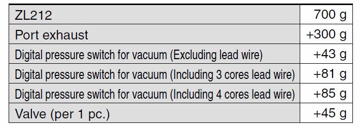
24 Weight Doc. no. ZL-OM

25 Exhaust Characteristics and Flow Characteristics of Ejector

26 Flow Characteristics Curve How to Read the Flow Characteristics Curves of Ejector/Vacuum Pump System - The flow characteristics curve shows the relationship between the vacuum pressure and the suction flow of the ejector/vacuum pump system. It shows that the vacuum pressure changes when the suction flow changes. Generally, the curve shows the relationship at the standard supply pressure of the ejector. In the graph on the right, P max means the maximum Suction flow vacuum pressure and Q max means the maximum suction flow. The value shown in this graph is what is shown in this operation manual and the catalogs as the specifications. The change of vacuum pressure is explained in sequence as follows. 1 When the vacuum port (V) is closed, the suction flow will be 0 and the vacuum pressure will reach its maximum (P max ). 2 When the vacuum port (V) is opened gradually, air will flow. (If there is bleeding air, the suction flow will increase, but the vacuum pressure will decrease.): [State of P1 Q1] 3 If the vacuum port (V) is opened fully, the suction flow will reach its maximum (Q max ), but the vacuum pressure will become almost 0 (atmospheric pressure). As described above, the vacuum pressure changes when the suction flow changes. Converting this to the adsorption state of the workpiece, the vacuum pressure reaches its maximum when the pad and the piping on the vacuum port (V) have no leakage. Vacuum pressure decreases when there is a lot of leakage when adsorbing a workpiece. When the amount of leakage and the maximum suction flow are equal, the vacuum pressure becomes almost 0, and it fails to adsorb the workpiece. Vacuum pressure will not increase if the product is used for adsorption of permeable workpieces or in an adsorption state with leakage. In such a case, sufficient verification and prior tests are required. Vacuum pressure
27 Vacuum Pressure Switch Assembly Handling Precautions Doc. no. ZL-OM ) Do not drop, hit or apply excessive shock (100m/s 2 ) to the product. The inner parts can be damaged leading to malfunction even if the sensor body is not damaged. 2) The tensile strength of the lead wire with connector is 35N. Exceeding this value can cause breakage. Be sure to hold the body when handling. 3) Avoid repeatedly bending or stretching the lead wire with connector. The lead wire may break if it is wired so that such force acts on it. If the lead wire can move, fix it near the body of the product. The recommended bending radius is 40mm or more. Contact SMC for more details if required. Connection 1) Incorrect wiring can damage the switch and cause malfunction. Connections should be done while the power supply is turned off. 2) Do not attempt to insert or pull out the connector from the pressure switch while the power is on. This may cause switch output malfunction. 3) Malfunctions stemming from noise may occur if the wire is installed in the same route as that of power or high-voltage cable. Wire the pressure switch independently. 4) Be sure to connect the ground terminal F.G. to ground when using a commercially available switch-mode power supply. Operating Environment The use of resin piping can cause static electricity to be generated, depending on the fluid. Therefore, when connecting the vacuum pressure switch assembly, take appropriate measures against static electricity at the customer s equipment side, and separate the grounding for the product from the grounding for any equipment which generates a strong electromagnetic noise or high frequency. Otherwise, static electricity can break the vacuum pressure switch assembly. Refer to SMC website (URL for details of the 2-color display high precision digital pressure switch, ZSE30A Series, other than those shown above
28 Troubleshooting Problems when using ejector troubleshooting Trouble Cause Countermeasures Initial adsorption failure (It fails to adsorb during the trial run.) The adsorption area is too small; the adsorption force is not strong enough compared with the weight of the workpiece and the force applied during transfer. Vacuum pressure is too small, due to leakage at the adsorption part or generation of a space between the pad and the workpiece due to deformation of the workpiece. Vacuum pressure is too small, due to leakage of vacuum pressure due to permeability of the workpiece. Vacuum pressure is too small due to leakage from the vacuum piping. Suction flow is too small. (Ejector performance is not high enough.) Suction flow is too small because the piping diameter is too small and the length is too long, causing restriction of the sucking flow of the ejector. Vacuum pressure and/ or suction flow are too small, making the supply pressure to the ejector insufficient. Vacuum pressure and/or suction flow are too small, due to clogging of the nozzle and the diffuser. Malfunction of supply valve Increase the lifting force. Increase the pad diameter Increase the number of pads. Doc. no. ZL-OM00801 Reduce the vacuum leakage (by increasing the vacuum pressure). Change the pad configuration. Increase the adsorption area. Change the pad material (e.g. to a material that fits the uneven surface). If the workpiece is thin, change to a suitable pad. Check the vacuum pressure and the suction flow. Change to an ejector with larger suction flow. Repair vacuum piping. Change to an ejector with larger suction flow. Increase the piping diameter and length on the vacuum side. Measure the supply pressure when the vacuum is generated, and increase the supply pressure to the standard supply pressure. Improve the line if the flow is insufficient. Especially when more than one product is operated at the same time in a manifold, the supply air can be insufficient, causing decrease of the supply pressure. Remove foreign matter and substances sticking to it. (Needs to be repaired.) Perform flushing and mount an air filter on the supply side to prevent it happening again. Measure the supply voltage to the solenoid valve. Revise the electrical circuit, wiring and connectors. Use within the rated voltage range
29 Trouble Cause Countermeasures Adsorption response is not quick enough. Internal capacity of the circuit on the vacuum side is too large for the ejector performance. The set vacuum pressure for the Reduce the internal capacity of the vacuum circuit. Change to an ejector with larger suction flow. Optimize the lifting force and change the setting to suction verification is too high, have the suction verification with the vacuum making the time before pressure as low as possible. it reaches the set value longer. Fluctuation of vacuum pressure Supply pressure fluctuates. Install a tank in the compressed air line on the supply side, and reduce the air consumption of other equipment. The generated vacuum pressure This is a phenomenon peculiar to ejectors which is fluctuates, making the exhaust caused when the supply pressure is a little lower noise intermittent at a certain than the standard supply pressure. supply pressure range. Increase or decrease the supply pressure a little. Vacuum Vacuum pressure is reduced, Replace the filter element with a new one. failure over due to clogging of the suction Increase the number of suction filters (such as time (absorbs filter (due to dust in the ZFA, ZFB and ZFC) properly environment on the vacuum initially.) side, foreign matter on the surface of workpiece, adsorption of humidity, etc.) Vacuum pressure is reduced, because of the clogging of the Clean the supply air. Control the drainage. silencer (due to foreign matter Mount an air filter and a mist separator. such as drainage and carbon Replace the silencer with a new one. particles in the supply air). Vacuum pressure and/or suction flow is reduced due to clogging of the nozzle and the diffuser. Remove foreign matter and substances sticking to it. (Needs to be repaired.) Mount an air filter on the supply side to prevent it happening again. Vacuum pressure and/or suction flow is reduced due to clogging of the nozzle and the diffuser. Remove foreign matter and substances sticking to it. (Needs to be repaired.) Mount an air filter on the supply side to prevent it happening again
30 Trouble Cause Countermeasures Vacuum failure Adsorbing part has some problem, such as deterioration of the vacuum Replace the vacuum pad with a new one. Revise the adsorption conditions (such as over time pad, or leakage due to frictional compatibility of the vacuum pressure with the (absorbs wear. pad/workpiece) properly initially.) The filter case gasket has come off when the filter element was replaced. Vacuum pressure leaks if the gasket has come off or out of the groove when maintenance of the filter was performed. Check if it is mounted properly. Defective operation caused by Shorten the energization time of the solenoid energization of solenoid valve for an extended period of time. (Energized for 10 minutes or more or operated with the duty ratio of valve. Provide forced ventilation in the operating environment in order to prevent temperature increase around the solenoid valve. 50% or more.) Workpiece Vacuum break flow is not large Open the vacuum break flow adjusting needle. is not enough. For the specification with individual port for released smoothly. release pressure supply port and air supply port, increase the release pressure at the releaser pressure supply port. The vacuum pad surface is worn Replace the vacuum pad with a new one. out, making it sticky. Revise the material and configuration of the vacuum pad. Use a special pad which has a blasted adsorption surface. (Made-to-order) Vacuum pressure is too high. Decrease the supply pressure to lower the vacuum pressure. Decrease the pressure in the piping on the vacuum side with a vacuum regulator. Workpiece sticks to the pad due to Use a conductive pad. static electricity. Vacuum break signal timing is inappropriate. If the pad is lifted before the workpiece is completely released from the pad, the workpiece is lifted together with the pad due to the viscosity of the pad. Revise the timing of the vacuum break and the lifting of the pad
31 If the countermeasures shown are not effective, there may be a problem with the product. In that case, stop using the product immediately without disassembling or repairing it. If any of the examples below are applicable, there may be a problem with the product. 1 It was used with a voltage other than the rated voltage. 2 Lubricant was contained in the supply air. 3 Liquid such as water was directly splashed onto the product body. 4) A strong impact was applied to the product. 5) Drainage and dust got mixed into the supply air. 6) Other actions corresponding to the precautions mentioned in this operation manual. When removing the product from the application, be sure to confirm that safety measures are taken, and shut down the compressed air supply and the power supply before removing the product
32 Revision history , Sotokanda, Chiyoda-ku, Tokyo JAPAN Tel: Fax: URL This manual is subject to change without prior notice SMC Corporation All Rights Reserved
Space Saving Vacuum Ejector Vacuum Pump System MODEL / Series / Product Number
 Doc. no. ZQ-OM00801 PRODUCT NAME Space Saving Vacuum Ejector Vacuum Pump System MODEL / Series / Product Number ZQ Series Contents Safety Instructions 2 Model Indication and How-to-Order 10 Mounting and
Prevents condensation
 Moisture Control Tube Prevents condensation in piping for small cylinders/air grippers. Diffuses water vapor in the piping to the outside! Water vapor Linear shape Suitable for applications where cylinders
Pressure Switches Precautions 1 Be sure to read this before handling.
 Pressure Switches Precautions 1 Design / Selection 1. Confirm the specifications. Products represented in this catalog are designed ony for use in compressed air systems (including vacuum). Do not operate
Moisture Control Tube
 Courtesy of CMA/Flodyne/Hydradyne Motion Control Hydraulic Pneumatic Electrical Mechanical (800) -80 www.cmafh.com Moisture Control Tube (Moiscon) Prevents! Prevents condensation in piping for small cylinders/air
Refrigerated Air Dryer
 Refrigerated Air Dryer For Use in Southeast Asia Applicable for the high-temperature environments of tropical regions Can be used in high-temperature environments Ambient temperature : Max. 45 C Inlet
Refrigerated Air Dryer
 Refrigerated Air Dryer Applicable for the high-temperature environments Ambient temperature : Max. 45 C Inlet air temperature : Max. 65 C Air flow capacity * IDF90-20, Dew point of 10 C, 60 Hz 16.4 m 3
Refrigerated Air Dryer
 Refrigerated Air Dryer For Use in Europe, Asia and Oceania Applicable for the high-temperature environments Ambient temperature : Max. 45 C Inlet air temperature : Max. 65 C Air flow capacity * IDFA90-23,
Model Selection. Data. Selection Graph. Selection Graph (2) Piping Capacity by Tube I.D.
 Piping Capacity by Tube I.D.") 8 Data Selection Graph Selection Graph (2) Piping Capacity by Tube I.D. Piping capacity V (L) Tube I.D. Tube length L (m) How to read the graph Example: For obtaining the capacity of tube I.D. ø5 and 1
8 Data Selection Graph Selection Graph (2) Piping Capacity by Tube I.D. Piping capacity V (L) Tube I.D. Tube length L (m) How to read the graph Example: For obtaining the capacity of tube I.D. ø5 and 1
Refrigerated Air Dryers
 Refrigerated ir Dryers Series F/U Standard/High Temperature ir Inlet Type Protect Pneumatic Equipment from Moisture! n air dryer removes the vapor from the moist compressed air delivered by the compressor,
Membrane Air Dryer IDG10,IDG10H IDG20,IDG20H
 Doc. No. AMX-OM-Q013 PRODUCT NAME Membrane Air Dryer MODEL / Series / Product Number IDG10,IDG10H IDG20,IDG20H Contents 1. Safety Instructions 1 2. Installations and Operations 3 3. Maintenances and Checks
Air Filter. Filter for Removing Dust and Drain in Compressed Air. Filter for Drain and Dust (Filtering Accuracy: 5µm)
") http://www.pisco.co.jp AIR PREPARATION ACTUATOR PLARAILCHAIN HARMO ROBOT PARTS Filter for Removing Dust and Drain in Compressed Air Air Filter 220 Filter for Drain and Dust (Filtering Accuracy: 5µm) Resin-made
http://www.pisco.co.jp AIR PREPARATION ACTUATOR PLARAILCHAIN HARMO ROBOT PARTS Filter for Removing Dust and Drain in Compressed Air Air Filter 220 Filter for Drain and Dust (Filtering Accuracy: 5µm) Resin-made
Refrigerated Air Dryer Large Size Series
 Refrigerated ir Dryer Large Size Series E Directive compliant (with E marking) For use in Europe, sia and Oceania Power Three-phase 380 V (For sia and Oceania) supply voltage Three-phase 400 V (For Europe)
Membrane Air Dryer IDG30 A IDG50 A IDG60LA,IDG60SA IDG75LA,IDG75SA IDG100LA,IDG100SA
 Doc. No. AMX-OM-Q014 PRODUCT NAME Membrane Air Dryer MODEL / Series / Product Number IDG30 A IDG50 A IDG60LA,IDG60SA IDG75LA,IDG75SA IDG100LA,IDG100SA Contents 1. Safety Instructions 1 2. Installations
Monitored Pneumatic Valves On Series Ported Manifold
 Monitored Pneumatic Valves On Series Ported Manifold Patented Technology SUITABLE FOR RISK CATEGORY 4 APPLICATIONS As per EN 954-1 & AS4024.1 SIL 3 as per IEC 61508 Applications Include: Pneumatic Presses
Reducing Valve Direct Mount Type with Pressure Gauge. Direct Mount Type (Compact size) Pressure Gauge is selectable.
 Pressure Gauge is selectable.") http://www.pisco.co.jp AIR PREPARATION ACTUATOR PLARAILCHAIN HARMO ROBOT PARTS Reducing Valve Direct Mount Type with Pressure Gauge 232 Direct Mount Type (Compact size) Pressure Gauge is selectable. Display
http://www.pisco.co.jp AIR PREPARATION ACTUATOR PLARAILCHAIN HARMO ROBOT PARTS Reducing Valve Direct Mount Type with Pressure Gauge 232 Direct Mount Type (Compact size) Pressure Gauge is selectable. Display
½ Monitored Pneumatic Valves On Series Ported Manifold
 ½ Monitored Pneumatic Valves On Series Ported Manifold Patented Technology SUITABLE FOR RISK CATEGORY 4 APPLICATIONS As per AS4024.1-Part 1502 & 1502 SIL 3 as per IEC 61508 & EN ISO 13849-1 Applications
Vacuum system component SELVACS
 Vacuum system component SELVACS Vacuum related components CC-796A 1 Wide variations for an assortment of applications New SELVACS vacuum components respond to a wide range of applications from fine work
Handling or using the product improperly and in disregard of the instructions with this mark might result in serious bodily injury or death.
 Please Read: Safety Precautions DC AC In order to ensure that this product is used safely, be sure that you read and understand the following precautions fully and use the product only as directed. Be
Vacuum unit ideal for controlling large flow rates Vacuum unit VSQ/VSQP series
 Vacuum unit ideal for controlling large flow rates Vacuum unit VSQ/VSQP series Features This 1.5 mm width vacuum unit is ideal for controlling large flow rates. A vacuum ejector unit and vacuum switching
½ Monitored Pneumatic Valve Patented Technology
 ½ Monitored Pneumatic Valve Patented Technology PBM4-S (Valve only air service equipment not included) SUITABLE FOR RISK CATEGORY 4 APPLICATIONS As per AS4024.1-Part 1502 & 1502 SIL 3 as per IEC 61508
INSTRUCTION MANUAL W-400
 USE and MAINTENANCE INSTRUCTION MANUAL Bellaria WBX WB GRAVITY SPRAY GUN Series LPH-400 WB en it fr es pt de se TECHNICAL DATA Classic Plus Series LPH-400 (LVLP) Classic Plus Nozzle_Needle set Combination
Filter for Drain and Dust (Filtering Accuracy: 5µm) Optional Selection of Direct Mount Pressure Gauge (Compact size).
 Optional Selection of Direct Mount Pressure Gauge (Compact size).") http://www.pisco.co.jp AIR PREPARATION ACTUATOR PLARAILCHAIN HARMO ROBOT PARTS Redcing Valve with Built-in Filter Filter Regulator 238 Filter for Drain and Dust (Filtering Accuracy: 5µm) Plastic made Bowl
http://www.pisco.co.jp AIR PREPARATION ACTUATOR PLARAILCHAIN HARMO ROBOT PARTS Redcing Valve with Built-in Filter Filter Regulator 238 Filter for Drain and Dust (Filtering Accuracy: 5µm) Plastic made Bowl
Document No. IZ*-OMP0064 C. P r o d u c t Ionizer. Model/Series. IZS4 Series
 Document No. IZ*-OMP64 C R P r o d u c t Ionizer Model/Series IZS4 Series 1 Contents Safety Instructions... 3 1. How to Order... 9 1-1. Ionizer... 9 1-2. Accessories... 1 1-3. Option... 11 2. Installation...
ULTRA LOW TEMPERATURE FREEZER. User Manual
 ULTRA LOW TEMPERATURE FREEZER User Manual Note:Kaltis reserves the right to modify any parts of this manual without prior notice. 1. No part of this manual may be reproduced in any form, or translated
USE and MAINTENANCE INSTRUCTION MANUAL GRAVITY. WS-400 EVO LS-400 Entech. SPRAY GUN Series. en it fr es pt de se
 USE and MAINTANCE INSTRUCTION MANUAL WS-400 EVO LS-400 Entech GRAVITY SPRAY GUN Series en it fr es pt de se TECHNICAL DATA WS-400 WS-400 EVO WS-400 Clear WS-400 Base WS-400-1301 EVO 1.3 170 365 260 WS-400-1401
Table of Contents. English
 OM-E0799E 000 English Thank you for purchasing VIVA ace Motor Kit. Please read this Operation Manual and the VIVA ace Basic Set Operation Manual carefully before use for operating instructions and care
Hollow Fiber Membrane Filter Type Air Dryer with Built-in Push-In Fitting
 http://www.pisco.co.jp PREPARATION ACTUATOR PLARAILCHAIN HARMO ROBOT PARTS Hollow Fiber Membrane Filter Type Air Dryer with Built-in Push-In Fitting Fiber Dry Series 188 Hollow Fiber Membrane Filter Type
Prevents condensation
 Moisture Control Tube Series Prevents condensation in piping for small cylinders/air grippers. Diffuses water vapor in the piping to the outside! Water vapor dditional power supply and works are not necessary!
AOYG18LFC OUTDOOR UNIT INSTALLATION MANUAL INSTALLATION MANUAL. For authorized service personnel only. PART NO
 AOYG8LFC OUTDOOR UNIT INSTALLATION MANUAL INSTALLATION MANUAL For authorized service personnel only. English PART NO. 93778639 93778639_IM.indb /20/20 6:07:25 PM AIR CONDITIONER OUTDOOR UNIT INSTALLATION
Warning Caution. Safety Precautions (Be sure to read these precautions before using our products.)
") INSTRUCTION MANUAL Infrared Temperature Sensor RD-715-HA No. RD71JE1 2013.09 Preface Thank you for purchasing our Infrared Temperature Sensor RD-715-HA. This manual contains instructions for the mounting,
INSTRUCTION MANUAL Infrared Temperature Sensor RD-715-HA No. RD71JE1 2013.09 Preface Thank you for purchasing our Infrared Temperature Sensor RD-715-HA. This manual contains instructions for the mounting,
VRA2000 Series Port size: Rc1/4, Rc3/8, G1/4, G3/4, 1/4NPT, 3/8NPT
 Refrigerating Desiccant High polymer membrane dryer VRA2000 Series Port size: Rc1/4, Rc3/8, G1/4, G3/4, 1/4NPT, 3/8NPT JIS symbol Air filter Auto. drain (Module unit) (Separate) Compact Precise (Related
INSTALLATION MANUAL. Split-type Air Conditioner (Cooling and Heating) Indoor Unit AQB18J6WC AQB24J2WC. Outdoor Unit UQB18J6WC UQB24J2WC
 Indoor Unit AQB18J6WC AQB24J2WC. Outdoor Unit UQB18J6WC UQB24J2WC") AQB8J6WC_IM_E_25864 2006.4.4 3:29 PM Page 7 INSTALLATION MANUAL Indoor Unit AQB8J6WC AQB24J2WC Outdoor Unit UQB8J6WC UQB24J2WC ENGLISH FRANÇAIS ESPAÑOL Split-type Air Conditioner (Cooling and Heating)
AQB8J6WC_IM_E_25864 2006.4.4 3:29 PM Page 7 INSTALLATION MANUAL Indoor Unit AQB8J6WC AQB24J2WC Outdoor Unit UQB8J6WC UQB24J2WC ENGLISH FRANÇAIS ESPAÑOL Split-type Air Conditioner (Cooling and Heating)
INSTRUCTION- AND MAINTENANCE MANUAL FOR ELECTROMAGNETIC AIR PUMP JDK-60, JDK-80, JDK-100, JDK-120
 INSTRUCTION- AND MAINTENANCE MANUAL FOR ELECTROMAGNETIC AIR PUMP MODEL : JDK-60, JDK-80, JDK-100, JDK-120 - release 29.01.2014 - We thank you for purchasing our air pump. Prior to use, it is kindly requested
DUCTED AIR CONDITIONER. Owner s Manual. KD Series KD24. Kaden Owner s Manual 1
 DUCTED AIR CONDITIONER Owner s Manual KD Series KD24 Kaden Owner s Manual 1 Table of Contents 1. Safety Precautions 4 2. Indoor Unit Parts and Major Functions 6 3. Care and Maintenance 8 4. Troubleshooting
Hollow Fiber Membrane Filter Type Air Drier Unit Type
 http://www.pisco.co.jp AIR PREPARATION ACTUATOR PLARAILCHAIN HARMO ROBOT PARTS Hollow Fiber Membrane Filter Type Air Drier Unit Type Dry Unit 202 No electric power supply is required. Air Filter, Mist
Complex Vacuum Generator realizing Stable and High-Speed Response Vacuum Generator VN Series
 EXTERNAL GENERATOR CONTROLLER PAD ACCESSORIES Complex Vacuum Generator realizing Stable and High-Speed Response Vacuum Generator Series 282 Suitable for semiconductor industry such as IC chip loader or
Original instructions. Operation Manual & Cautions
 Original instructions Operation Manual & Cautions Thank you for purchasing the Mistresa from Showa Denki. This manual explains the specifications for the [Mistresa units from CRN Series]. Please read the
Valve timing. Atmospheric air
 31.5-mm wide vacuum unit is designed to optimize the control of large vacuum flows. Vacuum generator and External vacuum controller are available for various needs. Three different types of vacuum generator
External Vacuum Controller with compact and lightweight body, achieving shorter blow-off time. External Vacuum Controller Series
 EXTERNAL PAD ACCESSORIES External Vacuum Controller with compact and lightweight body, achieving shorter blow-off time. External Vacuum Controller Series 37 Small in size and lightweight External Vacuum
SYSTEM Inverter Air Conditioners
 OPERATION MANUAL SYSTEM Inverter Air Conditioners MODEL Ceiling-mounted duct type low static pressure unit FXDQ07MVJU FXDQ09MVJU FXDQ12MVJU FXDQ18MVJU FXDQ24MVJU Read these instructions carefully before
INSTALLATION MANUAL. Split-type Air Conditioner (Cooling and Heating) Outdoor Unit UQB09JJWC UQB12JJWC. Indoor Unit AQB09JJWC AQB12JJWC
 Outdoor Unit UQB09JJWC UQB12JJWC. Indoor Unit AQB09JJWC AQB12JJWC") AQB09JJ6WC_IM_E_2585 2006.4.17 4:26 PM Page 17 INSTALLATION MANUAL Indoor Unit AQB09JJWC AQB12JJWC Outdoor Unit UQB09JJWC UQB12JJWC ENGLISH FRANÇAIS ESPAÑOL Split-type Air Conditioner (Cooling and Heating)
AQB09JJ6WC_IM_E_2585 2006.4.17 4:26 PM Page 17 INSTALLATION MANUAL Indoor Unit AQB09JJWC AQB12JJWC Outdoor Unit UQB09JJWC UQB12JJWC ENGLISH FRANÇAIS ESPAÑOL Split-type Air Conditioner (Cooling and Heating)
16 mm. Ionizer Nozzle type. Ion balance ±10 v. Slim design: Thickness dimension 16 mm RoHS compliant. Series IZN10
 Ionizer Nozzle type Series IZN10 Electrode needle contamination detector Outputs maintenance signal when detects stain or wear of an electrode needle always. Detects optimal maintenance time, reduced labor
Ioniser Nozzle type. Ion balance ±10 v. Slim design: Thickness dimension 16 mm RoHS compliant. Series IZN10
 Ioniser Nozzle type Dust removal and static electricity elimination by air blow Eliminates dust clinging to lamp covers. Spot type static electricity elimination Prevents electrostatic breakdown of electric
WINDOW TYPE COOLING MODEL AKT7F AKT9F REVERSE CYCLE MODEL AKT7U AKT9U FUJITSU GENERAL LIMITED
 OPERATING MANUAL OPERATING MANUAL BEDIENUNGSANLEITUNG MODE D EMPLOI MANUAL DE FUNCIONAMIENTO MANUALE DI ISTRUZIONI ΕΓΧΕΙΡΙ ΙΟ ΛΕΙΤΟΥΡΓΙΑΣ MANUAL DE INSTRUÇÕES ROOM AIR CONDITIONER WINDOW TYPE COOLING MODEL
TH450A-CRB TH550A-CRB THP550-CRB/TS3000
 TH450A-CRB TH550A-CRB THP550-CRB/TS3000 INSTRUCTION MANUAL CLEAN TYPE INDUSTRIAL ROBOT SPECIFICATIONS Notice Make sure that this instruction manual is delivered to the final user of Toshiba Machine s industrial
MIMAKI ENGINEERING CO., LTD.
 Daily Care Manual Request for daily care Inkjet printer is the precision machine that has highly delicate mechanism. Especially, little dust and paper powder may have effect on a head nozzle firing ink,
SX-300 SX-500 SX-700
 OPERATOR'S MANUAL AUTOCLAVE SX-300 SX-500 SX-700 Before starting operation, read this manual thoroughly for a complete understanding of the autoclave and its correct operation. Carefully store this operation
Split-type Air-Conditioner INSTALLATION MANUAL CONTENTS FOR INSTALLER MXZ-3B54VA MXZ-4B71VA. English
 Split-type Air-Conditioner MXZ-3B54VA MXZ-4B71VA INSTALLATION MANUAL English Refer to the installation manual of each indoor unit for indoor unit installation. IMPORTANT NOTES TO COMPLY WITH THE REQUIREMENTS
Ultrasonic Aroma Diffuser AD-SD1-CE
 Ultrasonic Aroma Diffuser AD-SD1-CE User's Manual For your safety and enjoyment, please read and understand this manual before using your product. After reading this manual, store in a safe and handy location
Prevents! Moisture Control Tube. Diffuses water vapor in the piping to the outside! Series IDK
 Moisture Control Tube Prevents! Prevents condensation in piping for small cylinders/air grippers. Diffuses water vapor in the piping to the outside! vapor Moisture control tube vapor All you have to do
DAIKIN ROOM AIR CONDITIONER. Operation Manual
 DAIKIN ROOM AIR CONDITIONER Operation Manual FDXM25F2V1B FDXM50F2V1B FDXM35F2V1B FDXM60F2V1B CONTENTS READ BEFORE OPERATION Safety precautions... 2 Names of parts... 4 CARE Care and Cleaning... 6 TROUBLE
Steam Trap BK 45 BK 45-U BK 45-LT BK 46
 Steam Trap BK 45 BK 45-U BK 45-LT BK 46 Original Installation Instructions 810437-08 Contents Foreword... 3 Availability... 3 Formatting features in the document... 3 Safety... 3 Use for the intended purpose...
Instruction Manual STATIC ERASER TOP FAN. Table of Contents
 STATIC ERASER TOP FAN Instruction Manual Thank you for having purchased Stat Clean No. L-90-E Read this instruction manual carefully before use. Keep it in a safe handy place for future reference. Table
INSTALLATION MANUAL SPLIT TYPE ROOM AIR CONDITIONER (PART NO )
") SPLIT TYPE ROOM AIR CONDITIONER INSTALLATION MANUAL (PART NO. 9312791019-01) This air conditioner uses new refrigerant HFC (R410A). The basic installation work procedures are the same as conventional refrigerant
SPLIT TYPE ROOM AIR CONDITIONER INSTALLATION MANUAL (PART NO. 9312791019-01) This air conditioner uses new refrigerant HFC (R410A). The basic installation work procedures are the same as conventional refrigerant
JT-SB116JH-G-NA JT-SB116JH-W-NA
 1311875HF4503 Hand dryer MODEL JT-SB116JH-G-NA JT-SB116JH-W-NA Unit color -G (Grey), -W (White) Model Name Display Position. Power voltage display position. INSTRUCTION MANUAL For User Read this manual
Operating instructions
 ebm-papst Mulfingen GmbH & Co. KG Bachmühle D-74673 Mulfingen Phone +49 (0) 793-0 Fax +49 (0) 793-0 info@de.ebmpapst.com www.ebmpapst.com CONTENTS. SAFETY REGULATIONS AND NOTES. Levels of hazard warnings.
THROUGH-WALL AIR-TO-AIR HEAT PUMP AND AIR CONDITIONER. Instruction Manual. Model AMB-12H
 THROUGH-WALL AIR-TO-AIR HEAT PUMP AND AIR CONDITIONER Instruction Manual Model AMB-12H PLEASE READ THIS INSTRUCTION MANUAL CAREFULLY BEFORE USING THIS UNIT. Table of Contents 1. SAFETY WARNINGS 2 2. CONSTRUCTION...
Operating Instructions
 Operating Instructions Laboratory Freezer SF-L6111W Please read these instructions carefully before using this product, and save this manual for future use. See page 18 for all Model No. 0 Note: 1. No
DEHUMIDIFIER OWNER S MANUAL. Read this manual carefully before operating the appliance and retain it for future reference.
 OWNER S MANUAL DEHUMIDIFIER ESPAÑOL FRANÇAIS Read this manual carefully before operating the appliance and retain it for future reference. Model : UD701KOG1 P/NO : MFL68026017 www.lg.com TABLE OF CONTENTS
Tornado Operations & Maintenance Manual
 Tornado Industries, LLC 333 Charles Court West Chicago, IL 60185 www.tornadovac.com Tornado Operations & Maintenance Manual MODEL NO. 99414 Form No. L9740AB Tornado Industries, LLC. All rights reserved
Tornado Operations & Maintenance Manual
 TORNADO INDUSTRIES 7401 W. LAWRENCE AVENUE CHICAGO, IL 60706 (708) 867-5100 FAX (708) 867-6968 www.tornadovac.com Tornado Operations & Maintenance Manual MODEL NO. 99690 BD 22/14, 99720 BD 26/14 L9722
Bar Fridge USER MANUAL MB46W
 Bar Fridge USER MANUAL MB46W CONTENTS Safety information... 2-3 Identifying parts of the fridge... 4 Transporting... 5 Installation... 5 Reversing the door... 6 Operating instructions... 7 Cleaning &
SYSTEM Inverter Air Conditioners
 OPERATION MANUAL SYSTEM Inverter Air Conditioners MODELS Floor standing type and Concealed floor standing type FXLQ12MVJU FXLQ18MVJU FXLQ24MVJU FXNQ12MVJU FXNQ18MVJU FXNQ24MVJU Carefully read this operation
WET & DRY GARAGE VAC 20L CAPACITY WATT 1.5M MOTOR TANK STEEL HOSE KP702 ON BOARD ACCESSORY STORAGE SUCTION STAINLESS
 WET & DRY GARAGE VAC 20L CAPACITY 1.5M SUCTION HOSE STAINLESS STEEL TANK ON BOARD ACCESSORY STORAGE 1250 WATT MOTOR KP702 Table of Contents 20L WET & DRY GARAGE VAC Know Your Product...1 Vacuum Safety
Bosch Split-Type Ductless Air Conditioner / Heat Pump
 Bosch Split-Type Ductless Air Conditioner / Heat Pump Climate 5000 AA Series User Manual 2 Bosch Split Type Ductless Air Conditioner / Heat Pump User Manual Data subject to change 01.2017 Bosch Thermotechnology
Utopian Split A/C. Thank you for purchasing this quality Split A/C system!
 Utopian Split A/C Thank you for purchasing this quality Split A/C system! Please read through this manual completely, and keep it in case you need to reference the information in the future. Any operation
Inverter Split-type Room Air Conditioner
 OWNER S MANUAL Inverter Split-type Room Air Conditioner Please read the operating instructions and safety precautions carefully and thoroughly before installing and operating your room air conditioner.
Installation and Maintenance Manual Forbes Marshall Tracer Line Trap FMMST63
 Installation and Maintenance Manual Forbes Marshall Tracer Line Trap Energy Conservation Environment Process Efficiency www.forbesmarshall.com Table of Contents 1. Preface...1 2. Important Safety Notes...1
Installation Manual. Vent Kit for Condensing Tankless Gas Water Heater
 Installation Manual NORITZ AMERICA CORPORATION Vent Kit for Condensing Tankless Gas Water Heater Model: N-FlexKit2"-35 Applicable Model NRC663-FSV Potential dangers from accidents during installation and
Operating Instructions
 Operating Instructions BA-003 Read and understand this manual before use. Keep this manual for future reference. CONFORMS TO UL STD.No.1017 Certified to CSA STD C22.2 No.243-10 For questions or concerns
Brazed Plate Heat Exchanger Instruction Manual for BX Series
 Brazed Plate Heat Exchanger Instruction Manual for BX Series Thank you very much for purchasing the Hisaka Brazed Plate Heat Exchanger. Read carefully this instruction manual to use the heat exchanger
Requests for Care and Maintenance
 Inkjet printer CJV300-30/60 Requests for Care and Maintenance This machine is a precision machine equipped with extremely fine mechanisms. Especially, the nozzle surface of the heads from which the ink
INSTRUCTION MANUAL CLEAN BELLOWS TYPE INDUSTRIAL ROBOT SPECIFICATIONS. Notice
 0 TH Series INSTRUCTION MANUAL CLEAN BELLOWS TYPE INDUSTRIAL ROBOT SPECIFICATIONS Notice 1. Make sure that this instruction manual is delivered to the final user of Toshiba Machine s industrial robot.
Split-type Air-Conditioner
 Split-type Air-Conditioner MXZ-2D52VA Installation Manual For INSTALLER This manual only describes the installation of outdoor unit. When installing the indoor unit, refer to the installation manual of
No.THD51E To prevent accidents arising from the use of this product, please ensure the operator using it receives this manual.
 Instruction manual Hygrothermo transmitter THD-500 Series No.THD51E1 2001.11 To prevent accidents arising from the use of this product, please ensure the operator using it receives this manual. Notes This
Read this Safety Guide first.
 LCD Projector User's Manual - Safety Guide Thank you for purchasing this projector. About The Symbols Read this Safety Guide first. Before using, read the user manuals for this projector to ensure correct
Instructions for installation and use English. More documents on: H B /09
 TM Instructions for installation and use English EN More documents on: www.zodiac-poolcare.com H0538700.B - 2015/09 Read this manual carefully before installing, maintaining or repairing this appliance!
Installation/Instruction Manual
 1510876HC8902 Pressurized ventilators (for device cooling) Model Blade diameter (cm) Indoor or outdoor EF-20UYS-UL EF-25UAS-UL EF-30UBS-UL 20 25 30 Indoor Installation/Instruction Manual For customers
Instruction Manual for Dust Collector
 YFAA11A-076ERe2 Instruction Manual for Dust Collector Dust Collector with Work Table Workrésa (WRM) Introduction Thank you for purchasing our Showa Denki s Dust Collector with Work Table (WRM) this time.
Owner s Manual CS
 Owner s Manual IMPORTANT NOTE: Read this manual carefully before installing or operating your new air conditioning unit. Make sure to save this manual for future reference. CS78421-548-754 Table of Contents
Operating Instructions
 Operating Instructions Air Conditioner Model No. Indoor Unit CS-PC9QKH CS-PC12QKH CS-PC18QKH CS-PC24QKH CS-PC28QKH Outdoor Unit CU-PC9QKH CU-PC12QKH CU-PC18QKH CU-PC24QKH CU-PC28QKH Operating Instructions
Refrigerated Air Dryer
 Refrigerated Air Dryer Large Size Series Tolerant of high temperature environment! Top of its class in the industry for the large air-cooled type Ambient temperature 45 Inlet air temperature 60 Energy
Ionizer (Static Remover) STABLO-EX Instruction Manual
 STABLO-EX Instruction Manual") 321-56879-21E Jan. 2009 For Electronic Balances Ionizer (Static Remover) STABLO-EX Instruction Manual Read the instruction manual thoroughly before you use the product. Retain this instruction manual for
321-56879-21E Jan. 2009 For Electronic Balances Ionizer (Static Remover) STABLO-EX Instruction Manual Read the instruction manual thoroughly before you use the product. Retain this instruction manual for
Owner s Manual SPLIT-TYPE ROOM AIR CONDITIONER
 Owner s Manual SPLIT-TYPE ROOM AIR CONDITIONER IMPORTANT NOTE: Read this manual carefully before installing or operating your new air conditioning unit. Make sure to save this manual for future reference.
GDDEM10 DEHUMIDIFIER
 GDDEM10 DEHUMIDIFIER SOCIABLE REMARK When using this dehumidifier in the European countries, the following information must be followed: DISPOSAL: Do not dispose this product as unsorted municipal waste.
Requests for Daily Care and Maintenance
 Inkjet printer TS500-800 Requests for Daily Care and Maintenance This machine is a precision machine equipped with extremely fine mechanisms. Especially, the nozzle surface of the heads from which the
Models Series Series
 Models 31800-Series 31801-Series INDUSTRIAL DIAPHRAGM PUMPS 4 GPM/15 LPM FEATURES Self-Priming Easy Installation Can run dry without damage Low Amp Draw Flow to 4 GPM/15 LPM Compact Size Thermal Overload
THERMAL SYSTEMS, INC. Installation and Operation Manual
 THERMAL SYSTEMS, INC. Installation and Operation Manual Revised September 2016 1. GENERAL SAFETY INFORMATION 1.1 Specification Never exceed the maximum allowable temperature or pressure ratings. Never
NEXXOS INVERTER USER MANUAL
 NEXXOS INVERTER USER MANUAL NIN412C2V32 NIN415C2V32 NIN520C2V32 NIN725C2V32 INVERTER MINI SPLIT SYSTEM WARNING The information contained in the manual is intended for use by a qualified service technician
PS-2/ES Automated pack & tag machine with IndES fastening system
 English Manual PS-2/ES Automated pack & tag machine with IndES fastening system Contents 1. Introduction 2. Important Safety Instructions 3. PS-2/ES 4. Unpacking the machine 5. Setting up the machine 6
Vent Kit for Condensing Tankless Gas Water Heater
 Installation Manual NORITZ AMERICA CORPORATION Vent Kit for Condensing Tankless Gas Water Heater Model: EZ2FVK-1 (Flex Vent 2" Kit 25 feet) Potential dangers from accidents during installation and use
Installation Instructions
 0908HN50 Lossnay Energy Recovery Ventilator Model: LGH-50RSDC-E (0-0V 50Hz) Installation Instructions (For use by dealer/contractor) Contents Safety precautions... Outline drawings... Standard installation
AUBREY with MAJOLICA PORTO Operation / Installation manual
 AUBREY with MAJOLICA PORTO Operation / Installation manual Contents Preparation before Installation (Specification Drawings) Usage condition Parts List / Accessory Parts Installation Procedure Safety Precautions
Models Series Series
 Models 3180-Series 3181-Series INDUSTRIAL DIAPHRAGM PUMPS Commercial Duty, 3 GPM/1 LPM FEATURES Sealless Easy Installation Run Dry Ability Flow to 3 GPM/1 LPM Self-Priming Low Amp Draw Thermal Overload
Single Handle Lavatory Faucet
 0GU3025 2007.5 TL170SD Single Handle Lavatory Faucet Installation and Owner s Manual RENESSE English Español Français Contents Important Safeguards------------1~2 Specifications -------------------------3
SYSTEM Inverter Air Conditioners
 OPERATION MANUAL SYSTEM Inverter Air Conditioners MODELS Ceiling-mounted Cassette type (Multi flow model) FXFQ12MVJU FXFQ18MVJU FXFQ24MVJU FXFQ30MVJU FXFQ36MVJU Read these instructions carefully before
Washing Machine. User manual WW9*K5*****/WW8*K5*****/WW7*K5***** Untitled :17:40
 Washing Machine User manual WW9*K5*****/WW8*K5*****/WW7*K5***** Untitled-6 1 2017-12-12 3:17:40 Contents Contents 4 What you need to know about the safety instructions 4 Important safety symbols 4 Important
Thank you for purchasing our Stat Clean No. BBZ-E. Read this instruction manual before use. Keep it in a safe handy place for future reference.
 your solution partner Instruction Manual Thank you for purchasing our Stat Clean No. BBZ-E. Read this instruction manual before use. Keep it in a safe handy place for future reference. Table of Contents
INSTRUCTION MANUAL EPH-121 CONTENTS
 INSTRUCTION MANUAL EPH-121 CONTENTS SAFETY PRECAUTIONS 1 NAME OF COMPONENT PARTS 5 HOW TO ASSEMBLE THE FRAME 6 OPEN AND CLOSE THE PANELS 7 OPERATION 9 TIMER OPERATION 10 SHUTDOWN 11 ROUTINE MAINTENANCE