Address: Building A, 4th Floor, Donghua Industrial Park, Sanwei Section,
|
|
|
- Roland Reed
- 5 years ago
- Views:
Transcription


1 \ 深圳市卓茂科技有限公司 SHENZHEN ZHUOMAO TECHNOLOGY CO., LTD. BGA Rework Station ZM-R590 Manual NO.:ZM-SMS Address: Building A, 4th Floor, Donghua Industrial Park, Sanwei Section, Bao'an Road, Bao'an, Shenzhen, China Telephone: Fax:
2 Preface Shenzhen ZhuoMao Technology Co., Ltd. is a high-tech enterprise involved in research, development, production and marketing. Since its establishment, with strong technical force, faithful business philosophy, a sound sales network, comprehensive and thoughtful after-sales service, through the absorption and the introduction of foreign advanced technology, we improved ourselves and won customers trust & supports in the field of BGA rework systems and peripheral auxiliary equipment. Company's product are sold in most cities in China and exported to Japan, South Korea, North Africa, Vietnam, Southeast Asia, the Middle East, Europe and the United States etc. We got a strong vitality and higher visibility in the same industry. Our company will continue adhering to the idea of "profession, innovation and integrity", to provide our customers with more efficient high-quality and convenient services! Your smile is always Zhuomao s constant pursuit. Thank you so much for choosing BGA rework station ZM-R380C of Shenzhen ZhuoMao Technology Co., Ltd. Before you operate the machine, please read the manual book carefully to make sure of the safety and Superior performance of the machine. As technology continues to update, Zhuo Mao Technology Co., Ltd. has the right to modify specifications of the product before notice. Please take care of the accessories of the machine. If you have any doubt and special requirements of this equipment, you may contact with our company at any time. The Company reserves the final right to interpret the Manual
3 Contents 1st Introduction Features 3 2nd installation 4 3rd Product specifications and technical parameters 5 4th Introduce of the main structure 5 (1)Structure description 6 (2)Features 7 5th procedures Installation and operation 7 (1) Upper temperature settings 11 (2)use of an external computer 18 (3)operation 20 6th Reballing process 32 7th Equipment repair and maintenance 33 (1) Replacement of the upper heating wire 33 (2) Replacement of the lower heating plate 24 (3) Maintenance 24 8th precautions 36 Normal BGA welding and disordering parameters
4 1st Features of ZM-R Choose imported high-precision materials (temperature sensor, heater) to control the BGA desoldering & soldering procedures precisely. 2. There are three independent heating areas from top to bottom. The first and second temperature areas can control many groups & sections of temperature parameters at the same time. The third area preheats the PCB thoroughly to achieve the best welding effect. 3. Choose imported high-precision thermocouple to detect top/down temperature precisely, with a function of over-temperature protection. 4. Top & bottom temperature areas heat independently, A cross-flow fan cools rapidly to protect the PCB from deformation when welding. 5. After finishing desoldering & soldering, there is an alarming. The machine is equipped with a vacuum suction pen to facilitate the removing of BGA after desoldering. 6. Use a V-groove equipped with a flexible fixture for PCB positioning to protect the PCB. 7. For large thermal capacity of PCB or other high-temperature and lead-free welding requirements, all can be handled easily
5 2nd Installation 1 Be away from flammable, explosive, corrosive gas or liquid. 2 Avoid damp places, the air humidity is less than 90%. 3 Temperature -10 ~ 40, avoid direct sunlight, prolonged sun exposure. 4 No dust, fibers and metal particles floating in the operational environment. 5 The place of installation needs to be flat, solid, no vibration. 6 Place heavy objects on the body are strictly prohibited. 7 Avoid the affection of direct airflow, such as air-conditioners, heaters or fans. 8 The back of rework station should be reserved 30CM for heat dissipation. 9 The placing table ( mm) be flat, the relative level of a height 750 ~ 850 mm. 10 Distribute wiring must be handled by a qualified professional technician, the main line is 1.5 square feet. Equipment must be well grounded. 11 Switch off the power after use, Power must be disabled if a long-term no need
6 3rd Specifications 1 Power supply : AC220V±10% 50/60Hz 2 Power consumption: 4.8KW Max 3 Heater power: top heater: 0.8KW;bottom heater: 1.2KW ;IR: 2.7KW 4 Electric material: PLC,support computer communication. 5 Temperature control: K-type closed-loop thermocouple, top and bottom heating independently, temperature error±3 6 Positioning: V-groove fixture for PCB positioning 7 PCB size: MAX mm Min 22 22mm 8 Machine dimension: mm 9 Weight:45kg 10 Machine color:black 4th main structure description (1) structure introduction - 5 -
7 - 6-01Y-axisadjust02Z-axisadjust03topheater04topnozle05botomheater07botomheater08botomheaterswitch09PCBsplint06PCBboardsupporter13cooling/vacuumautoandmanual14tophotairadjust16light/start/stop15temperaturesensor12botomPLC11topPLC10cros-flowfan(2) function introduction NO name function Use method 1 Y-axis adjustment handle Adjust the top heater right and left R-back, L-forward 2 Z-axis adjustment handle Adjust the top heater up and down R-up, L-down 3 Top heater Heating the BGA from top Adjust by Z-axis 4 Top nozzle Make hot air focus on BGA Make suitable place 5 Bottom heater Heating the BGA from bottom 6 PCB supporter To support the PCB To adjust the screw to do 7 Bottom heater Preheat the PCB board 8 Bottom heater switch Control the area of heating 9 PCB splint To support PCB board Put the PCB board on it 10 Cross-flow fan Cool the PCB board It will work auto
8 Top programmable temperature Controller Bottom programmable temperature Controller cooling/vacuum auto and manual 14 Top air flow adjust 15 Temperature sensor 16 light/start/stop after heating To control the top heater temperature To control the bottom heater temperature Control cooling/vacuum auto and manual switch To adjust top hot air flow Connect an external galvanic to measure the actual temperature To control lighting, start and stop after heating Reference to the manual Reference to the manual Turn right and left to adjust Connect to the temperature sensor directly 5th Program setting and operating instructions (1) Top temperature Program setting: 1 Thermostat button interface and Features introduction - 7 -
9 PV PV410 PV SV PTN PUN PRO STEP EV COM MV MAN AT SV AL1 OUT1 OUT2 DISP SELE SET PROG RUN PROG PTN AUTO HAND PAR SET B I P NO. item explain 1 PAR SET AUTO HAND parameter setup key Auto / Hand switching button Number increase Number decrease 2 PIN PUN PROG SET PROG DISP PROG Curve group number increase Run/stop button for curve running curves program parameter setting button Display select OUT1 3 OUT2 4 STEP 5 PROFILE Output 1 indicator Output 2 indicator Curve program segment NO. Display, showing the running NO. of the curve procedure curves Procedures monitoring light, when running up of the slope section, it will display "/", when running in the platform section, it will - 8 -
10 6 PIN OP3 7 AT RUN 8 PV window SV/MV/EV 9 window SV 10 MV EV AL1 11 MAN COM display "-", when running down of the slope segment, it will display "\". Curve program number display, display curve program number 3rd Output indicator PID self-tuning indicator Curve Running indicator Show measured values Display settings, the output value or run the remainder of section, press DISPSELECT key, it will show display items switch Setting indicator, lower display shows the set value, the indicator will be lit Output indicator, lower display shows the value, the indicator will be lit Outside test light, lower display shows the set value, this indicator will light up 1st alarm indicator Manual control indicator ----when you use the manual control, the indicator light when sending data the indicator light 2 Setting process First turn on the power supply, choose the number for saving the temperature profile: (set groups) press PTN button (can save 10 groups temperature profiles), Press PTN groups will be changed (1, 2, 3, 4, 5, and 0) choose one of them for temperature profiles (We take 1st group for example) - 9 -
11 PV DISP SV EV MV COM MAN SET PROG RUN AUTO HAND 1 RUN SV AL1 PIN PAR SET PV410 PIN PRO STEP OUT1 OUT2 Bip (1) Slope setting (r) (Per second increase in temperature) Press SET button enter into temperature curve,r1 stands for slope (the temperature will rise at the speed of 3 in one second) 3.00 stands for 3 /second, press number increase button to adjust. Press PAR button enter next step. PV SV r EV MV COM MAN DISP SET PROG RUN AUTO HAND 1 RUN SV AL1 PIN PAR SET PV410 PIN PRO STEP OUT1 OUT2 Bip (2) Temperature setting (L)(as following picture) Press number increase button to adjust,l1 means that this is the temperature for segment1(l2 means that the temperature for segment 2, and so on),160 stands for preheating temperature 160. Press PAR button for confirming and enter to next step
12 PV SV L EV MV COM MAN DISP SET PROG RUN AUTO HAND 1 RUN SV AL1 PIN PAR SET PV410 PIN PRO STEP OUT1 OUT2 Bip (3) Time setting (d)(as pictured) D1 stands for the time how long the temperature stays at this stage. (30 means that when the temperature reach 160, it will last 30 seconds.) Press number increase button to adjust. Press PAR button for confirmation and enter to next step. PV SV d1 30 EV MV COM MAN DISP SET PROG RUN AUTO HAND 1 RUN SV AL1 PIN PAR SET PV410 PIN PRO STEP OUT1 OUT2 Bip (4) The remaining seven-segment temperature settings are same as above exactly. (5) If you do not want to set 8 segments, then you can change as you wish. For example, if you just need 6 segments, then after you set the sixth segment, and then press PAR SET to enter the seventh segment. When you set slope of the segment 7, then you press button until SV show END. Press button, it will show the picture as following, press PAR SET button,
13 it means confirmation. (6) After setting finished, it will show the picture as following.( This feature is as follows: the maximum limit temperature, prohibit changes) PV SV Hb 300 EV MV COM MAN DISP SET PROG RUN AUTO HAND 1 RUN SV AL1 PIN PAR SET PV410 PIN PRO STEP OUT1 OUT2 Bip 3 bottom temperature settings: Such as REX--C10 show actual temperature PV show setting temperature move set SV down up RKC SET REX-C10 Setting Method:
14 1) Hold down the adjustment button for 5-6 seconds, then the setting of the temperature a bit flash, press numerical increase (decrease) key to change. And then move button to move the modified adjusted value of 10, and finally to 100, after finished, press the SET to confirm. ALM PV OUT1 OUT2 SV AT SET RKC REX-C10 (2) the use of an external computer The device can connect with an external computer, you can observe two temperature curves of the head of internal heating wire and external measurement of galvanic through the computer interface, and you also can set the temperature, time and other parameters through the computer, but also can achieve data transfer between computer and instrument, store many curves and facilitate to print out. (Note: This feature is limited to the upper heating control) Statement: the related temperature parameters of the equipment can
15 be set-up and stored completely through the instrument age, but in order to set the temperature more user-friendly, more intuitive, and easy to store, and print the temperature curve, our company specially developed this software! 1 Software Install ( 1 ) Lowest requirement of computer configuration for software installment a CPU:P Ⅲ 800 b. Memory:128M C display card: 4M D driver: CD ROM e. Serial Communication Interface (2) Software Installation, a Put the video into the video driver, open CD driver, run V2.08setup appear language select. Choose English and Click Next to enter Picture

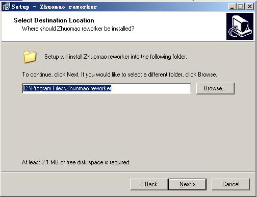
16 Figure 1 Figure

17 b Click Next to enter Picture 2 c After enter Picture 2,click Next button,enter Picture 3 d Click Next,enter Picture 4 e Click Next,enter Picture 5 f Click Install,enter Picture 6,start installing. g Click Finish,finish installing process. Figure

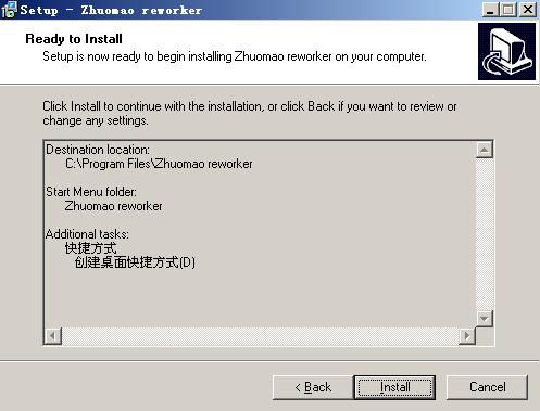
18 Figure 4 Figure

19 Figure 6 Figure 7 3 Using of software
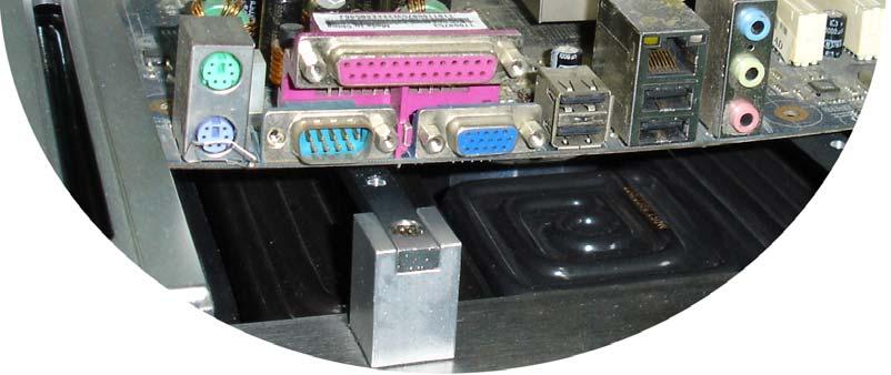
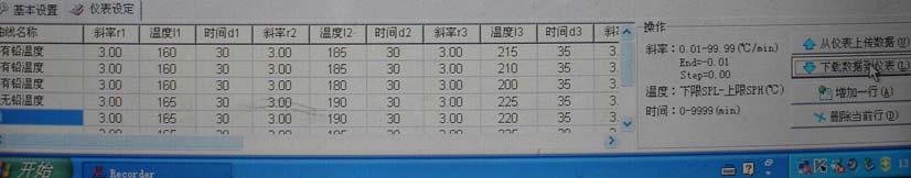
20 1)Connect the computer series port and machine communication port with the enclosed date cable. 2)Turn on the power of the equipment. Zhuomao reworker.lnk 3) Click on the desktop,enter into temperature curve recorder system interface(picture 10) 4)Set the temperature, time, slope parameter for every segment. a Click Profiles setting,the interface will enter into (Picture 9), according to welding BGA and solder ball to set the parameter for each segment. And for specific date and operating parameters, please refer for the construction book. b Note 1:This software is for showing the temperature curve and recorder, the software does not have the motion control functions, for the movement of the machine need manual adjustment. c Note 2:The related temperature profiles, you can set through the meter on the machine. However, in order to facilitate the users for temperature setting, in particular for the temperature curve showing, save and print, so we develop and expand this software. (5) Click download Controller,so the temperature for just setting can be down load to the programmable controller. (6) Fix the nozzle according to the BGA chip, pay attention to the top heater work normal or not; if not, stop heating, and check what the problem is. Otherwise it will damage the heating wire easily as the
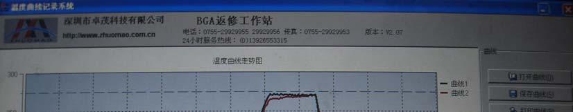
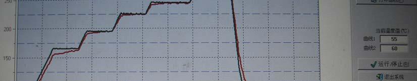
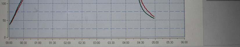
21 high temperature. (7) Fix the PCB board on the PCB pallet, and make the heating part just below the nozzle. (8) Adjust Z-axis and Y-axis to make the nozzle on the top of the heating part, the height between them is 2~5mm.(Figure 8) (9) Click Run/Stop,the machine will carry out heating motion. (10) At this time you can see the temperature curve.(figure 9) (11) Curve 1(Green)shows:The actual measurement of heater temperature (12) Curve 2(Red)shows:The actual measurement of external galvanic (13) After heating, it will automatically run cooling system; It will reduce the deformation of the PCB board, shorten the work cycle and improve the work efficiency through cooling. (14) During the process of heating,click Run/Stop,or click Stop on the control panel,heating process will be stop. (15) Click "Exit System" button, the computer will quit the application programmer. 3 Development Features Instruction (figure 10 figure 11) (1) Upload from Controller :Click this button can upload the internal instrument parameter from controller to the computer; it
22 can set a group of data each click.(note: the programmable controller can save 10 groups itself) (2) download Controller : Click this button can download the parameter from computer to the controller; (3) Save :After using the software for heating, Profile View curve display page will show the two temperature curve, use this button can save the curves to any position on the computer hard disk. (4) Open :Through using this button can pick up the temperature curve stored in computer. (5) Print :Through an external printer can easily print the current curve. (6) "X-axis maximum number (minutes) "number setting window: The maximum setting of the horizontal of the curve screen (7) "Y-axis maximum number (Degrees Celsius) "number setting window: The maximum setting of the Ordinate of the curve screen

23 Figure


24 Figure 9 Figure 10 Figure
25 5 Computer settings (upper heater) (1) Click on the icon, the screen display as (Figure 10), bottom of the screen for setting the temperature curve parameters, drag the cursor point 160, with reference parameter set reference value in the table of parameters to be modified. (2) After the setting of the paragraphs parameter, click on as (Figure 10) "to download data to the instrument" so that the data can be stored in the instrument, (Remark: The group number displayed on the meter number during transmission is the NO. of the data that transmitted, the original number of the data in the instrument will be overwritten). 6 Operation (1) Turn on the Main Power Switch, then check whether there is cold air blow out from the top of the hot air nozzle, if not, it is strictly prohibited to turn on switch, otherwise it will burn the top heater; (2) Set the procedures as the above method, and install the computer data lines correctly, turn on the power supply. (3) Install the PCB board which is need to weld and the appropriate nozzle; make the centers of the nozzle are on the center of the PCB board, turning Z-axis adjustment handle of the heater, so that the nozzle is at the height of 3-5mm of the top surface of the PCB board
26 (4) Presses the start, the system will automatically heating and welding; The temperature trend curve will appear on the screen; (5) After welding, the system will automatically stop heating. And then turn the Z-axis adjustable handle of the heater upward, check the welding results. Welding process is completed. (6) The use of external measuring galvanic 1 Function (1) More accurate to measure the actual temperature of the part to be heated during the welding process. (2) It is easy to move, so that it can be convenient to measure the temperature of the different parts of the welded components during the heating process. (3) Calibration role, through appropriate adjustment, it will make the temperature of the welding parts get close to the set temperature as much as possible. 2 Installation (1) Check the galvanic lines, whether there are disconnected phenomena or not. (2) Insert the galvanic Plug into the "outer galvanic Socket on the control panel according to the positive and negative mark
27 (3) After GALVANIC installed correctly, click "DiSP SELE" button on the upper instrument panel, (the button which is used to switch the displaying item), switch to "TIME", the corresponding galvanic current temperature will be displayed in the second line of instrumentation on the "SV" display window. (4) Stated: "DiSP SELE" is the button to switch the displaying items, when press it, the downstream sequence of display windows display setting no., output no., the remainder of the number of segments of running, corresponding to Panel "SV", "MV", "TIME "indicator light. 3 Measurement (1) PCB board will be installed on the rework station, with the galvanic fixed on the PCB board using foil stickers. (2) Adjust the height of the probe with the probe galvanic head located in the top 1-2mm of the test site (as shown in Figure 12)

 4 Adjust the up and down")
28 Figure 12 Figure 13 3 Adjust the related mechanical adjustment knob, so that the heating part just below the hot-air tube. (as shown in Figure 13) 4 Adjust the up and down adjustment knob of the hot-air head to make
29 the distance between the edge of PCB board side and the hot-air head is 3-5mm. 5 Implementation of the welding / disordering process, that is to start the process of upper and lower heater. 6 Then it will show two curves of the green and red on the computer monitor screen 7 Curve 1, the actual measurement temperature of the internal galvanic of the top heater (green) 8 Curve 2, the actual measurement temperature of the external galvanic curve (red) 4 Using the outer galvanic to adjust the temperature curve Statement: In this operation, it may be due to improper operation to cause the temperature deviation of the device or even lose control, please caution! Take the upper hot-air tube as an example to make detailed description of adjustment method (1) Set the temperature, the time, the slope and so on parameters of the upper heater (2) Adjustment process proposed to do on a waste circuit board in order to prevent damage to the circuit board and on-board electronic components
30 (3) Implementation of the above process (3), installed the outer measured galvanic, in which the top of the PCB board just below the hot-air tube. (4) Close the lower part of the heating process, click on "Start" button to start the heating process, which will on the computer monitor screen will be displayed on the upper curve of the measured temperature (green) and external galvanic measuring temperature (red) the two curves (5) Green curves represent the actual measurement of the galvanic temperature curve of the upper heating wire inside, the red curve represents the actual measurement of the galvanic temperature outside. the smaller the gap between the green curve and red curve, the closer between the actual temperature and set temperature of the heating parts, more standard of the upper heating process; On the contrary, the greater the gap between the two curves, the greater the actual temperature deviate from the set temperature, the more non-standard of the upper part during the heating process. 6 If the deviation between the two curves is too much, you should make the appropriate adjustments 7 The specific adjustment method is as follows, because of the impact of the system processes and the environmental, deviations in the objective is inevitable. If the temperature deviation does not affect the
31 normal welding and desordering, non-professionals should avoid the following corrective actions! A If the outer galvanic curve (red) lower than the upper one(green), adjust the internal hairdryer galvanic probe upward; B If the outer galvanic curve (red) higher than the upper one(green), adjust the internal hairdryer galvanic probe downward; C Adjustment must be small, try to control the amplitude of accommodation in 1mm or less; D Repeated several adjustments; E During adjustment process, the heated of galvanic probe is strictly prohibited from contacting with any objects, so as not to affect the accuracy of measuring temperature; F After temperature adjustment, you should fix the probe, to avoid the probe vibration measurement of the temperature of the equipment G The method of the adjustment applies only to the two parallel curves in a smooth uniform deviation, and it is invalid to the temperature which is from top to bottom jitter free-laws regulating! H The upper part of the internal galvanic Duct location: Remove the upper heater nozzle, at a distance of 2-3cm at the edge wind-cone. I operating the standard procedure to avoid the high-temperature burns!
32 8 There is no booster thermocouple temperature curve on the bottom of the computer screen, so you have to adjust the process of the lower part of the heaters by visual. 9 fixed the galvanic line with foil stickers on the bottom of PCB board (as opposed to the upper heater set back on the PCB board), so that the probe of the booster thermocouple is located just 2mm above the mouth of the bottom hot-air nozzle, and adjust the mechanical parts, make the upper hot-air nozzle deviate from the heated parts to avoid cold air affect the temperature of the heated parts. 10 Set the parameters of the lower heating temperature, while closing the upper part of the heating process, click on "Start" button to start heating 11 Now you can see "SV which displayed on the panel of the upper programmable thermostat (also click on the "DiSP SELE" button of the upper instrument panel, and switch to the position of the "TIME" indicator light) is the temperature of the external galvanic, with the abbreviation as the outer temperature; and PV is the temperature of the internal galvanic, with the abbreviation as the bottom temperature. 12 The caution is same as the top heater. 13 The methods of adjustment: A If the outer temperature is lower than the bottom, you should adjust

33 the lower internal galvanic probe downward. B If the outer temperature is higher than the bottom, you should adjust the lower internal galvanic probe upward. 6th Reballing Process 1 Fix the BGA chip on the base of our universal reballing station; Adjust the four slipper blocks to fix the chip to make it on the center of the reballing kit. 2 Select the appropriate steel mesh according to chip type. Fix the steel mesh to the ceiling cover and tighten it with 4 M3 screws, covered with lid. Adjust 4 Jimmy on the base to meet the suitable height required. 3 Observe the hole on steel mesh which should be completely coincide with the solder holes on BGA. If not coincide, we must remove the cap to reposition to ensure steel mesh holes aligned with the chip, and then lock the four screws. 4 Locking two no spring fixed slide, remove the BGA chip and coated with a thin layer of solder flux, card the chip into the base again, covered with lid(make sure

34 luminumupperheatop nozzleathe right direction). 5 Put into solder ball, clench hands and gently swaying reballing station to ensure the solder ball completely filled in the holes and pour out extra solder balls. 6 Place the reballing station on the flat location; Remove the lid, carefully scored BGA chips. Observe the chip, if individual solder balls are not in the hole rightly, please correct it with forceps. 7 It is convenient to use our different types of repair stations or welding machine to fix solder ball. Heat solders balls on the BGA to soldering it on BGA, thus reballing finished. 7th Repair and Maintenance (1) Upper heater:(pictured) fa n top fixer plastic connector heating wire fixer high-tem perature insulating paper dh eating wire cover
35 1. The replacement of fan: Remove the heater cover, and remove the insulation fiber block, then you can replace the fan. 2. The replacement of heating wire Remove the heater cover the insulation fiber block and fan, remove the upper fixed block, then take out the hot wire. Then it can be replaced. Note: When you change the heating wire; it must be wrapped by High-temperature insulating paper. (2) Replacement of the lower hot air heating wire: (Pictured) body 02 Heating Duct 03 Heating wire 04 heating wire fixture 05 plastic connector 06 fan holder 07 fan 08 Heater cover 09 fan holder bolt 10 fan bolt
36 11 heater cover bolt Replacement of the lower hot-air heating wire: 1) Remove the heater bolts, and then remove the heater cover. 2) Demolition of fans, fan holder, plastic connector and fan wire fixture, take out the hot wire. Then you can replace the heating wire, (3) The bottom heating panel (pictured) heating pad lock screw fixed plate heating panel card heating box 1 Replacement of heating plate: 1). Demolition of locking screws (4), remove the heating plate and the assembly of the fixed plate, placed on the table which is covered with a sponge (with heating plate surface facing down). 2). Removed the fixed heating plate card, you can break down the fixed plate and heating plate assembly, remove the heating plate then it can be replaced
37 8th safety precautions (1) BGA Rework Station ZM-R590 use AC220V power, working temperature may up to 400, Improper operation may cause damage to the equipment and even endanger the safety of the operator. Therefore must strictly abide the following: 1) No directly fan or other blowing air to the station when working, otherwise it may cause damage to the equipment or components as the distortion of heater thermometric; 2) prohibited flammable gases or liquid around the machine; After booting, forbidden combustibles touch high temperature district and peripheral metal parts, otherwise it will easily cause fire or explosion; 3 ) To avoid high temperature scald, forbidden touching high temperature fever zone during working. PCB board still warm when completed, operation process should take necessary protective measures; 4) PCB board should be placed on V type support shelves and used slider pairs to support PCB board in the centre; e. Metal or angular and sharp objects are avoided on touch screen surface; 5) upper and lower heater inlet must not be blocked, otherwise heating wire will be damaged; 6) After work, please guarantee natural cooling for 5 minutes, then
38 Switch off; 7) if metal objects or liquid fall into rework station during working, you should power off immediately, unplug power plug, until it cooled, then eradicate litter and dirt; it will be influenced if grease on the heating panels and accompanied by odor when rebooting. Please keep the machine clean and timely maintenance. 8 ) when appears abnormal warming or smoke on the machine, immediately disconnect power and notify technical service personnel to repair it; Remove the connections data line between computer and devices, hold the plug to unplug the data line, to avoid damaging internal connection. (2)if it belongs to one of the following situations, and other damage caused by them; It will not be in the Company guarantee scope! 1 Failing uses the method in manual to operate in wrong conditions or environmental operation;; 2 The Company product outside reasons; 3 Not the transformation and maintenance of the company; 4 not accordance to the method stipulated when using the products ; 5 unpredictable situation that the company scientific technical level not reached; 6 Natural disasters or man-made destruction of non-responsibility of the company premises
39 Normal BGA welding and disordering parameters (for reference) 1 The temperature curve of lead welding 41*41 the temperature setting of the BGA welding: preheating insulation heating welding1 welding2 cooling upper time bottom time slope IR *38 the temperature setting of the BGA welding: preheating insulation heating welding1 welding2 cooling upper time bottom time slope IR *31 the temperature setting of the BGA welding:
40 preheating insulation heating welding1 welding2 cooling upper time bottom time slope IR 180 The upper is the reference temperature of the lead BGA 2 The temperature curve of Lead-free welding 41*41 the temperature setting of the BGA welding: preheating insulation heating welding1 welding2 cooling upper time bottom time slope IR
41 38*38 the temperature setting of the BGA welding: preheating insulation heating welding1 welding2 cooling upper time bottom time slope IR *31 the temperature setting of the BGA welding: preheating insulation heating welding1 welding2 cooling upper time bottom time slope IR 210 The upper is the reference temperature of the lead-free BGA Such as set 0 when the demolition of the cooling section of BGA
SHENZHEN ZHUOMAO TECHNOLOGY CO., LTD. Manual Zm-R5850. NO. ZM-SMS Address: Building A3, 4th Floor, Donghua Industrial Park, Sanwei
 SHENZHEN ZHUOMAO TECHNOLOGY CO., LTD. Manual Zm-R5850 NO. ZM-SMS-05-03 Address: Building A3, 4th Floor, Donghua Industrial Park, Sanwei Section, Bao'an Road, Bao'an, Shenzhen, China Telephone 0755-29929955
Manual 深圳市卓茂科技有限公司 SHENZHEN ZHUOMAO TECHNOLOGY CO.,LTD. BGA Rework Station ZM-R5830 NO.:ZM-SMS-05-10
 深圳市卓茂科技有限公司 SHENZHEN ZHUOMAO TECHNOLOGY CO.,LTD. BGA Rework Station ZM-R5830 Manual NO.:ZM-SMS-05-10 Address: Building A, 4th Floor, Donghua Industrial Park, Sanwei Section, Bao'an Road, Bao'an, Shenzhen,
Instruction Manual. ZM-R6200 Rework Station. comercialreballing.ro tel Cluj-Napoca, Calea Motilor 43, RO
 comercialreballing.ro www.bgareballing.ro tel. 0264-590022 Cluj-Napoca, Calea Motilor 43, RO ZM-R6200 Rework Station Instruction Manual NO.:ZM-SMS-06-08A Contents 1st Introduction Features 3 2nd installation
Shenzhen SCOTLE Technology 深圳市玉海源科技有限公司 SHENZHEN SCOTLE TECHNOLOGY LTD
 深圳市玉海源科技有限公司 SHENZHEN SCOTLE TECHNOLOGY LTD IR6000 Scotle- BGA Rework Station Manual Catalog 1. Company Profile 2. Installations 3. Safety Cautions 4. Structures and Specifications 5. Operations 6. Touch
SHENZHEN ZHUOMAO TECHNOLOGY CO., LTD. BGA Rework Station ZM-R5860C Instruction Manual
 SHENZHEN ZHUOMAO TECHNOLOGY CO., LTD. BGA Rework Station ZM-R5860C Instruction Manual Contents A. Preface...2 B. Structures...3 C. Specifications...4 D. Operations...5 E. Installation...12 F. Packing list...13
BGA Rework Station TOUCHBGA GM490 User Manual
 BGA Rework Station TOUCHBGA GM490 User Manual touchbga.com 1. BGA Rework Station Setting Up 2. BGA Rework Station Safety Precautions 3. BGA Rework Station Main Specification 4. BGA Rework Station Operation
S ATION EWORK ST BGA R
 BGA REWORK STATIONS INTRODUCTION InterElectronic Hungary Ltd. offers equipments, machines and different materials (ESD) of different production technologies (SMT/THT/LED). Including high quality, special
touchbga.com TOUCHBGA BGA Rework Station GM330 IR+HR User Manual
 TOUCHBGA BGA Rework Station GM330 IR+HR User Manual Table of contents 1. GM330 BGA rework station features 1.1.Safety Instrouctions 1.1.1.Electric Safety 1.1.1.Operation Safety 1.1.3.Environmental requirements
中龙集团 Dragon Group China Limited BIRD BIRD AC BGA Rework Station. User Manual.
 BIRD AC-5000 BGA Rework Station User Manual Contents A. Brief introduction to company B. Safety Instructions I.Electric Safety II.Operation Safety III.The operation and conservation condition of products
S ATION EWORK ST BGA R
 BGA REWORK STATIONS INTRODUCTION INTEON BGA rework systems allows attractive price and high quality performance for lead free process. INTEON BGA rework systems assure an optimum of process stability by
LY R690 Touch Screen BGA Rework Station User Manual
 LY R690 Touch Screen BGA Rework Station User Manual Catalogue I. Parameters II. Installation features III. Control panel Introduction IV. Temperature curve setting V. Temperature curve reference VI. BGA
BGA Rework Station Pro-660
 BGA Rework Station Pro-660 Pro-660 BGA Rework Station Description PRO-660 is the strengthen version of Pro-650. With all the function 650 have, it can handle bigger PCB High-definition optical alignment
Instruction Manual QUICK 855PG PROGRAMMABLE SMD REWORK STAION
 QUICK 855PG PROGRAMMABLE SMD REWORK STAION Instruction Manual Thank you for purchasing our SMD Rework station. The unit is exclusively designed for reworking and soldering SMD component. Please carefully
I760B-DX BGA Rework System. Operation Manual
 I760B-DX BGA Rework System Operation Manual Thank you for purchasing our IR Rework System. The system is exclusively designed for reworking and soldering SMD component. Please carefully read this manual
HRS55PG PROGRAMMABLE SMD REWORK STAION. Instruction Manual. Thank you for purchasing our SMD Rework station. The unit is exclusively designed for
 HRS55PG PROGRAMMABLE SMD REWORK STAION Instruction Manual Thank you for purchasing our SMD Rework station. The unit is exclusively designed for reworking and soldering SMD component. Please carefully read
touchbga.com TOUCHBGA BGA Rework Station HR6000 User Manual
 TOUCHBGA BGA Rework Station HR6000 User Manual Table of contents 1. HR6000 BGA rework station features 1.1.Safety Instrouctions 1.1.1.Electric Safety 1.1.1.Operation Safety 1.1.3.Environmental requirements
QUICK BGA2005. Operation Manual
 QUICK BGA2005 BGA/SMD Rework System Operation Manual Thank you for purchasing our BGA/SMD Rework System. The system is exclusively designed for reworking and soldering SMD component. Please carefully read
QUICK BGA2015 BGA/SMD Rework System. Operation Manual
 QUICK BGA2015 BGA/SMD Rework System Operation Manual Thank you for purchasing our BGA/SMD Rework System. The system is exclusively designed for reworking and soldering SMD component. Please carefully read
ACHI. BGA Rework Station. User Manual. ИТ Сервис, г. Екатеринбург 1
 BGA Rework Station User Manual ИТ Сервис, г. Екатеринбург 1 http://uralsale.ru, sales@uralsale.ru Safety Instrouctions I. Electric Safety II. Operation Safety III. The operation and conservation condition
QUICK BGA2015. Precision BGA Rework System. Features:
 QUICK BGA2015 Precision BGA Rework System Features: 1. IR2015 Infrared Reflow Soldering Section: Infrared temperature sensor monitors BGA surface temperature to ensure precise temperature technical window.
Intelligent Lead Free Soldering Station OPERATION and MAINTENANCE MANUAL
 Intelligent Lead Free Soldering Station Sensor in front High frequency heating Digital Calibration Rapid recovery of temperature OPERATION and MAINTENANCE MANUAL Thank you for purchasing a lead free soldering
QK-IR2005. User s Manual
 QK-IR2005 BGA/SMD Rework System User s Manual Thanks for purchasing our IR BGA/SMD Rework System. The system is exclusively designed for reworking and soldering SMD component. Please carefully read this
34737-TL SMD REWORK STATION
 34737-TL SMD REWORK STATION 1. Production Summary 1.1 Specification Rated power Input voltage Air Pump Capacity Hot Air Temperature Sensor 1.2 Function 320W AC110-130V, 60Hz Diaphragm pump 24L/min(max)
Mini SMT Reflow Oven Model: T-961
 Mini SMT Reflow Oven Model: T-961 Taian Puhui Electric Technology Co., Ltd http://www.tech168.cn Http://www.tech168.cn 1/13 Features: 1. This machine selects IR and hot air heating technology controlling,
NOTEBOOK I 760 BGA/SMD Rework System. Operation Manual
 NOTEBOOK I 760 BGA/SMD Rework System Operation Manual Thank you for purchasing our IR Rework System. The system is exclusively designed for reworking and soldering SMD component. Please carefully read
POT-100C / POT-102C POT-200C /POT-202C
 TAIYO ELECTRIC IND.CO.,LTD. SOLDER POT OWNER'S OPERATION MANUAL POT-100C / POT-102C POT-200C /POT-202C POT-200C OWNER'S OPERATION MANUAL Before using the solder pot, read this Owner's Operation Manual.
RD-500V RD-500SV ESD SMT REWORK SYSTEM
 RD-500V All-IN-ONE Advanced Technology SMT Rework Station Compatible For The Rework Of All Different Types Of SMT Components Compact & Stable, Designed for 7d/24h Shifts SMT REWORK SYSTEM RD-500SV ESD
LED New Light Source Reflow Oven. Model: T-960
 LED New Light Source Reflow Oven Model: T-960 Features: 1. This machine selects the intelligent level sirocco and rapid infrared heating technology controlling, equipped with special design wind wheel,
SMD Rework Technology Complete solutions
 SMD Rework Technology Complete solutions Reliable rework All MARTIN rework systems utilize advanced convection and infrared heating technologies, delivering extremely repeatable and efficient heating.
SMD Rework Technology Complete solutions
 SMD Rework Technology Complete solutions Reliable rework Extensive tasks: EXPERT 10.6 All MARTIN rework systems utilize advanced convection and infrared heating technologies, delivering extremely repeatable
Operating Manual. for. SMD/BGA Rework System IR860
 Operating Manual for SMD/BGA Rework System IR860 Thank you for choosing XYTRONIC SOLDERLIGHT IR860 Infra-Red rework system. This appliance is specially designed for SMD/BGA rework and also very convenient
BGA Rework Station User Manual
 BGA Rework Station User Manual 1 I preface Brief introduction to company II IR6500 and IR6000 comparison Safety Instrouctions I. Electric Safety II. Operation Safety III. The operation and conservation
Int 937. Soldering Station. Instruction Manual. Correct Disposal of this product
 Int 937 Soldering Station Instruction Manual Correct Disposal of this product This marking indicates that this product should not be disposed with other household wastes throughout the EU. To prevent possible
WHA 3000V Hot Air Station
 WHA 3000V Hot Air Station Operating Instructions Version 1.1 Page 1 of 14 Table of contents 1. Description 5 Technical data 5 2. Commissioning 6 2.1 Manual operating mode 6 2.2 Automatic operating mode
474A+ INSTRUCTION MANUAL DESOLDERING STATION
 1 2 7 474A+ DESOLDERING STATION INSTRUCTION MANUAL Thank you for purchasing 474A+ Desoldering Station. Please read the manual before using the unit. Keep manual in accessible place for future reference.
AOYUE 968A+ INT. Deluxe Repairing System INSTRUCTION MANUAL
 AOYUE INT 968A+ Deluxe Repairing System INSTRUCTION MANUAL Thank you for purchasing Aoyue INT 968A+ Repairing System. It is important to read the manual before using the equipment. Please keep manual in
Digital LEAD FREE. Soldering Soldering. Temperature range. Station. N1-06 Nozzle ø0.6 N1-08 Nozzle ø0.8 N1-10 Nozzle ø1.0 N1-13 Nozzle ø1.3. ø2.
 Desoldering Tool High-Power Desoldering Tool Digital Nozzle not included N2 Soldering Soldering (Option) (Option) Desoldering Vacuum pump built-in type desoldering tool Digital display ensures easy and
Instruction Manual. SMD Rework Station with Vacuum Pickup TABLE OF CONTENTS
 SMD Rework Station with Vacuum Pickup Instruction Manual Thank you for purchasing the HAKKO FR-803 SMD Rework Station. This unit features: Digital control and display of time and temperature Display of
AOYUE. Int 852A+ pro Int 852A++ pro. SMD Rework Station INSTRUCTION MANUAL. (Centigrade / Fahrenheit switchable)
") This appliance can be used by children aged from 8 years and above and persons with reduced physical, sensory or mental capabilities or lack of experience and knowledge if they have been given supervision
This appliance can be used by children aged from 8 years and above and persons with reduced physical, sensory or mental capabilities or lack of experience and knowledge if they have been given supervision
SMD Rework Station with Vacuum Pickup. Instruction Manual
 SMD Rework Station with Vacuum Pickup Instruction Manual Thank you for purchasing the HAKKO FR-803 SMD Rework Station. This unit features: Digital control and display of time and temperature Display of
474A+ TIP CARE AND USE INSTRUCTION MANUAL DESOLDERING STATION
 TIP CARE AND USE. Tip Temperature High soldering temperatures can degrade the tip. Use the lowest possible soldering temperature. The excellent thermal recovery characteristics ensure efficient and effective
Table of Contents DIGITAL DRYING OVEN. Features. Setup. Cautions. Description of the parts. Temperature Controls. Maintenance and Storage
 Table of Contents 1 Features 2 Setup 3 Cautions 4 Description of the parts 5 Temperature Controls 6 Maintenance and Storage 7 Troubleshooting 8 Warranty 9 Technical Specifications -2- Safety warnings Before
QUICK EA-A10. BGA/CSP Rework Station. Operation Manual
 QUICK EA-A10 BGA/CSP Rework Station Operation Manual Thank you for purchasing our BGA/SMD Rework System. The system is exclusively designed for reworking and soldering SMD component. Please carefully read
Beijing TECHNICAN CO.,Ltd.
 BGA Rework Station User Manual Beijing TECHNICAN CO.,Ltd. 1 www.easybga.com preface I Brief introduction to company II IR6000 BGA rework stations feature Safety Instrouctions I. Electric Safety II. Operation
AOYUE INT. Advanced Repairing System NT 701A++ INSTRUCTION MANUAL. Correct Disposal of this product
 This appliance can be used by children aged form 8 years and above and persons with reduced physical, sensory or mental capabilities or lack of experience and knowledge if they have been given supervision
over 100 are used all over India by our top customers many with repeat... repeat orders
 MFRS500SUS reliable & caring since 1976 All the 3 functions of Hot Air Reflow, Thru-Hole De & fine SMD Soldering, work independent ly at the same time No external ompressor required, needs Mains Supply
RD-500V RD-500SV ESD SMT REWORK SYSTEM
 RD-500V All-IN-ONE Advanced Technology SMT Rework Station Compatible For All Kind Of Rework For Different Type Of SMT Components Compact & Stable, Designed for 7d/24h Shifts SMT REWORK SYSTEM RD-500SV
Infrared Moisture Determination Balance FD-610. Operating Manual
 Infrared Moisture Determination Balance FD-610 Operating Manual Infrared Moisture Determination Balance Safety Notes Improper use of the infrared moisture tester in violation of the following safety notes
Desoldering Tool. New. Portable Desoldering Tool. Packing List. Specifications
 Desoldering Tool New Portable Desoldering Tool Nozzle included Power switch and adjustable temperature control built in the handle Use of high thermal efficiency N61 series nozzles Reduction of solder
DIGITAL INDICATING CONTROLLER FCS-23A INSTRUCTION MANUAL
 DIGITAL INDICATING CONTROLLER FCS-23A INSTRUCTION MANUAL Preface Thank you for purchasing our Digital indicating controller FCS-23A. This manual contains instructions for the mounting, functions, operations
OPERATING MANUAL FOR LF-852DII HOT-AIR S.M.D. REWORK STATION
 OPERATING MANUAL FOR LF-852DII HOT-AIR S.M.D. REWORK STATION Thank you for choosing XYTRONIC LF-852DII S.M.D. Rework Station. This tool is specially designed for soldering, desoldering Surface Mount Devices
QUICK 3202 OPERATION MANUAL. Lead Free Soldering Station
 QUICK 30 Lead Free Soldering Station OPERATION MANUAL Thank you for purchasing the unit. It is designed for lead free soldering. Please read this manual carefully before use and keep it for future reference.
Communications None RS-232C RS-422* RS-485* BCD Transmission output*/** (4 to 20 ma) E5AX- E5AX- L(M)A02 L(M)A03
 E5AX- E5AX- L(M)A02 L(M)A03") Digital Controller A 96 x 96-mm (DIN) Digital Process Controller Optimum PID control with feed-forward control circuitry. High accuracy (+0.3% FS +1 digit max.). Replaceable Output Units. Models with communications
Digital Controller A 96 x 96-mm (DIN) Digital Process Controller Optimum PID control with feed-forward control circuitry. High accuracy (+0.3% FS +1 digit max.). Replaceable Output Units. Models with communications
SMD Rework Station TABLE OF CONTENTS
 SMD Rework Station Thank you for purchasing the Hakko 850D SMD Rework Station. This unit features digital control and display of hot air temperature. Please read this manual before operating the Hakko
JOVY SYSTEMS RE User Manual Rev. 1.00
 JOVY SYSTEMS RE-7550 User Manual Rev. 1.00 Index - Introduction... 3 - Copyrights and Liability disclaimer........ 3 - Specifications.. 4 - Safety/ Caution instructions....... 4 - RE-7550 hardware description......
DSSHP06G Intelligent Lead Free Soldering Station INSTRUCTION MANUAL
 DSSHP06G Intelligent Lead Free Soldering Station Sensor in front High frequency heating Digital Calibration Rapid recovery of temperature INSTRUCTION MANUAL Thank you for purchasing this lead free soldering
Int2930. Soldering Station. Instruction Manual
 Int2930 Soldering Station Instruction Manual Thank you for purchasing the Aoyue Int2930 Soldering Station. Please read the manual before using the unit. Keep manual in accessible place for future reference.
User Manual. Digi-Sense TC9500 Advanced Multiparameter Temperature Controller with Thermocouple, Thermistor, and RTD Inputs
 User Manual Digi-Sense TC9500 Advanced Multiparameter Temperature Controller with Thermocouple, Thermistor, and RTD Inputs Models 89800-03 and 89800-04 THE STANDARD IN PRECISION MEASUREMENT Table of Contents
WHA 3000P Hot Air Station
 WHA 3000P Hot Air Station Operating Instructions Version 2.3 Weller Tools GmbH Carl-Benz-Str. 2, 74354 Besigheim, Germany Tel: +49 (0) 7143 580-0, Fax: +49 (0) 7143 580-108 Table of contents Page 1. Description
RC-112 Two Speed Heat Pump 3 Stage Heat / 2 Stage Cool With Energy Efficient Control
 O M N I S T A T ELECTRONIC COMMUNICATING THERMOSTAT Installation Manual RC-112 Two Speed Heat Pump 3 Stage Heat / 2 Stage Cool With Energy Efficient Control Document Number 13I00-5 November, 1997 CONTENTS
Laser engraving & cutting machine installation. Operation Manual
 Laser engraving & cutting machine installation Operation Manual 1 Preface Thank you for purchasing our laser engraving and cutting machine. This machine is a professional and high technical product consisting
E S D REWORK SYSTEM 3 IN 1, I702 USER S GUIDE
 E S D REWORK SYSTEM 3 IN 1, I702 USER S GUIDE Thank you for purchasing the Rework system. This manual describes the use and maintenance of the Rework system. Please read it before reading the manual, keep
JOVY SYSTEMS RE-7500 User Manual Rev Index
 JOVY SYSTEMS RE-7500 User Manual Rev. 1.60 Index - Introduction... 3 - Copyrights and Liability disclaimer........ 3 - Specifications.. 4 - Safety/ Caution instructions...... 4 - RE-7500 hardware description......
SMD Rework Station with Vacuum Pickup. Instruction Manual
 SMD Rework Station with Vacuum Pickup Instruction Manual l Thank you for purchasing the HAKKO FR-803B SMD Rework Station. This unit features: l Digital control and display of time and temperature l Display
PR-L2466W- PA. Operating Instructions. High Performance Refrigerator PR-L2466W-PA
 Operating Instructions High Performance Refrigerator PR-L2466W- PA PR-L2466W-PA Please read these instructions carefully before using this product, and save this manual for future use. See page 11 for
OPERATING INSTRUCTIONS
 OPERATING INSTRUCTIONS FOR CARPET PRO UPRIGHT VACUUMS MODELS : CPU-75, CPU-75T, CPU-85, CPU-85T Before operating the vacuum, please read these instructions completely. Index Important Safety Instructions.............................................................2
SMD REWORK SYSTEM. Instruction Manual 401H000505
 401H000505 SMD REWORK SYSTEM Instruction Manual Thank you for purchasing our SMD Rework unit. The unit is exclusively designed for reworking and soldering SMD component. Please carefully read this manual
INSTALLATION MANUAL. Decoration Panel Provided with Filter Auto Cleaning Function Self Cleaning decoration panel BYCQ140D7GW1 BYCQ140D7GFW1
 INSTALLATION MANUAL Decoration Provided with Filter Auto Cleaning Function Self Cleaning decoration panel BYCQ0D7GW BYCQ0D7GFW BYCQ0D7GW BYCQ0D7GFW Installation manual Contents. SAFETY PRECAUTIONS....
RC-90 / RC-90B Single Stage Heat/Cool Thermostat for Zone Control Systems Installation Instructions
 RC-90 / RC-90B Single Stage Heat/Cool Thermostat for Zone Control Systems Installation Instructions DESCRIPTION The RC-90 is a precision digital thermostat designed for 24 VAC single stage heating and
User Manual. Digi-Sense TC9600 Advanced Multiparameter Temperature Controller with Thermocouple, Thermistor, and RTD Inputs
 User Manual Digi-Sense TC9600 Advanced Multiparameter Temperature Controller with Thermocouple, Thermistor, and RTD Inputs Models 89800-13 and 89800-14 THE STANDARD IN PRECISION MEASUREMENT Table of Contents
INT. Lead-Free Repairing System INSTRUCTION MANUAL
 INT 2702 Lead-Free Repairing System INSTRUCTION MANUAL Thank you for purchasing Aoyue Int2702 Repairing System. It is important to read the manual before using the equipment. Please keep manual in accessible
aoyue Int732 INSTRUCTION MANUAL Game Console Reworking System
 aoyue Int732 Game Console Reworking System INSTRUCTION MANUAL Thank you for purchasing Aoyue Int732 Game Console Reworking System. It is important to read the manual before using the equipment. Please
EVAPORATIVE AIR COOLER SERVICE MANUAL
 EVAPORATIVE AIR COOLER SERVICE MANUAL CAUTION: Before servicing the unit, read the Safety Precautions in this manual. Only for authorized service. MODEL NO.: CL30XC & CHL30XC (INDOOR USE ONLY) CONTENT
Operation Manual. (Version 1.5.1)
") VWR symphony TM Gravity Convection General Incubator Operation Manual (Version 1.5.1) VWR symphony Gravity Convection General Incubator 414004-610, 414004-612, 414004-614, 414004-616 414004-611, 414004-613,
VWR symphony TM Gravity Convection General Incubator Operation Manual (Version 1.5.1) VWR symphony Gravity Convection General Incubator 414004-610, 414004-612, 414004-614, 414004-616 414004-611, 414004-613,
SS-969 SMD Rework Station
 SS-969 SMD Rework Station 99 Washington Street Melrose, MA 02176 Phone 781-665-1400 Toll Free 1-800-517-8431 Visit us at www.testequipmentdepot.com User s Manual 1 st Edition, 2011 2011 Copy Right by Prokit
RC801/803/ B 16E1 Fiber-Optic Multiplexer (Rev. M) User Manual. Raisecom Technology Co., Ltd. (04/2005)
 User Manual. Raisecom Technology Co., Ltd. (04/2005)") RC801/803/805-480B 16E1 Fiber-Optic Multiplexer (Rev. M) User Manual Raisecom Technology Co., Ltd. (04/2005) 1. Cautions Please read the following notices carefully before installing and using the device,
RC801/803/805-480B 16E1 Fiber-Optic Multiplexer (Rev. M) User Manual Raisecom Technology Co., Ltd. (04/2005) 1. Cautions Please read the following notices carefully before installing and using the device,
USER S MANUAL NKP. Duct heater for supply air pre-heating with external control
 USER S MANUAL Duct heater for supply air pre-heating with external control CONTENTS Contents... 2 Safety requirements... 2 Purpose... 4 Delivery set... 4 Designation key... 4 Technical data... 5 Design
atten Color ^ Back to Top Clients Login Username: Password: Home About Us Products News Video Service Support Join Us Contact Us
 1 of 7 30/10/2012 11:16 Color ^ Back to Top atten Clients Login Username: Password: Press ESC to close Home About Us Products News Video Service Support Join Us Contact Us You are here: Home > Products
AUTOMATIC ICE-CUBE MAKER - INSTRUCTIONS AND WARNINGS
 AUTOMATIC ICE-CUBE MAKER - INSTRUCTIONS AND WARNINGS Dear Customer, Congratulations on having chosen a quality product which will certainly fully meet your expectations. Thank you for having purchased
METCAL QX2 CONVECTION REWORK SYSTEM USER GUIDE
 METCAL QX2 CONVECTION REWORK SYSTEM USER GUIDE Test Equipment Depot - 800.517.8431-99 Washington Street Melrose, MA 02176 - TestEquipmentDepot.com Metcal is an OK International Company Copyright 1999,
STATIC ELIMINATOR I443A INSTRUCTION MANUAL
 STATIC ELIMINATOR I443A INSTRUCTION MANUAL Thank you for purchasing a Static Eliminator. It is designed to eliminate the static charge from a charged object. Please read this manual before operating the
INSTALLATION MANUAL. Split-type Air Conditioner (Cooling and Heating) Outdoor Unit UQB09JJWC UQB12JJWC. Indoor Unit AQB09JJWC AQB12JJWC
 Outdoor Unit UQB09JJWC UQB12JJWC. Indoor Unit AQB09JJWC AQB12JJWC") AQB09JJ6WC_IM_E_2585 2006.4.17 4:26 PM Page 17 INSTALLATION MANUAL Indoor Unit AQB09JJWC AQB12JJWC Outdoor Unit UQB09JJWC UQB12JJWC ENGLISH FRANÇAIS ESPAÑOL Split-type Air Conditioner (Cooling and Heating)
AQB09JJ6WC_IM_E_2585 2006.4.17 4:26 PM Page 17 INSTALLATION MANUAL Indoor Unit AQB09JJWC AQB12JJWC Outdoor Unit UQB09JJWC UQB12JJWC ENGLISH FRANÇAIS ESPAÑOL Split-type Air Conditioner (Cooling and Heating)
Series Temperature Controller Instruction Sheet
 Series Temperature Controller Instruction Sheet Thank you very much for purchasing DELTA A Series. Please read this instruction sheet before using your A series to ensure proper operation and please keep
Operating Instructions ERSA IR 500 A SMT / BGA Rework System 3BA
 SMT / BGA Rework System 3BA00011-00 01 Contents: 1. Introduction 1.1 Product information 1.2 General Information on the Operating Instructions 2. Technical Specifi cations 3. Safety Instructions 4. Start
RC-101 Heat Pump Real Time Pricing System 2 Stage Heat / 1 Stage Cool
 O M N I S T A T ELECTRONIC COMMUNICATING THERMOSTAT Installation Manual RC-101 Heat Pump Real Time Pricing System 2 Stage Heat / 1 Stage Cool Document Number 13I00-4 January, 1997 Copyright 1997 Home Automation,
DIGITAL INDICATOR JIR-301-M
 DIGITAL INDICATOR JIR-301-M Instruction Manual Preface Thank you for purchasing our digital indicator JIR-301-M. This manual contains instructions for the mounting, functions, operations and notes when
Operation and Maintenance Manual for the SODRTEK ST 325 Digital Convective Soldering/Desoldering System P/N
 Operation and Maintenance Manual for the SODRTEK ST 325 Digital Convective Soldering/Desoldering System P/N 5050-0537 TITLE PAGE General Information...3 Introduction...3 Microprocessor Control...3 ST 350
ELECTRONIC COMMUNICATING THERMOSTAT
 O M N I S T A T ELECTRONIC COMMUNICATING THERMOSTAT Installation Manual RC-81 Single Stage Heat/Cool Real Time Pricing System Document Number 13I00-2 January, 1997 Copyright 1997 Home Automation, Inc.
AUTOMATIC GRANULAR ICE FLAKER
 AUTOMATIC GRANULAR ICE FLAKER INSTRUCTIONS AND WARNINGS 24480 rev. 01 It is strictly forbidden to reproduce this instruction manual or any part thereof. Dear Customer, Congratulations on choosing a
Handling or using the product improperly and in disregard of the instructions with this mark might result in serious bodily injury or death.
 Please Read: Safety Precautions DC AC In order to ensure that this product is used safely, be sure that you read and understand the following precautions fully and use the product only as directed. Be
Temperature Controller
 E5AN Temperature Controller Temperature Controller OMRON Corporation Industrial Automation Company Industrial Devices and Components Division H.Q. Measuring Components Department Shiokoji Horikawa, Shimogyo-ku,
NTS STRUME IN N-ON DE
 DEN-ON INSTRUMENTS INTRODUCTION InterElectronic Hungary Ltd. offers equipments, machines and different materials (ESD) of different production technologies (SMT/THT/LED). Including high quality, special
Big Board Rework. Joerg Nolte Ersa GmbH Wertheim, Germany
 Big Board Rework Joerg Nolte Ersa GmbH Wertheim, Germany Abstract As indicated in previous abstracts to the rework topic, customer demands in the field of PCB repair are constantly increasing. Lately technical
User s Manual WS-69TB30 / WS-69TB36 (22 ) WS-69TB42 / WS-69TB48 (22 ) WS-69TS30 / WS-69TS36 (18 ) WS-69TS42 / WS-69TS48 (18 )
 WS-69TB42 / WS-69TB48 (22 ) WS-69TS30 / WS-69TS36 (18 ) WS-69TS42 / WS-69TS48 (18 )") www.windsterhood.com User s Manual LINER SERIES WS-69TB30 / WS-69TB36 (22 ) WS-69TB42 / WS-69TB48 (22 ) WS-69TS30 / WS-69TS36 (18 ) WS-69TS42 / WS-69TS48 (18 ) NOTE: PLEASE INSPECT HOOD IMMEDIATELY UPON
www.windsterhood.com User s Manual LINER SERIES WS-69TB30 / WS-69TB36 (22 ) WS-69TB42 / WS-69TB48 (22 ) WS-69TS30 / WS-69TS36 (18 ) WS-69TS42 / WS-69TS48 (18 ) NOTE: PLEASE INSPECT HOOD IMMEDIATELY UPON
Tornado Operations & Maintenance Manual
 TORNADO INDUSTRIES 7401 W. LAWRENCE AVENUE CHICAGO, IL 60706 (708) 867-5100 FAX (708) 867-6968 www.tornadovac.com Tornado Operations & Maintenance Manual MODEL NO. 99690 BD 22/14, 99720 BD 26/14 L9722
OPERATING INSTRUCTIONS
 CLEANMAX OPERATING INSTRUCTIONS FOR CLEANMAX STANDARD SERIES UPRIGHT VACUUMS MODELS : CMS-1T CMS-1N Before operating the vacuum, please read these instructions completely. Index Important Safety Instructions............................................................
Installation Guide for inbiox60 Series Access Control Panel
 Installation Guide for inbiox60 Series Access Control Panel Version: 1.0 Date: April, 2011 About This Manual This manual is a guide to installation and connection of the inbiox60 series access control
Figure 1-1 Furnace Front Elevation
 FURNACE EQUIPMENT 1.1 Furnace Description The LA-306 is a compact, near-infrared, conveyor belt furnace for laboratory and general purpose thermal processing in the range of 100-980 ⁰C in a controlled
INSTRUCTION MANUAL FOR TOUCH PANEL MONITORING UNIT CMT-220-K
 INSTRUCTION MANUAL FOR TOUCH PANEL MONITORING UNIT PREFACE Thank you for your purchase of our Touch panel monitoring unit. This manual contains instructions for the mounting, functions, operations and
Designed in the UK. Rapide Ultimate. User Guide Vax Rapide Ultimate
 Designed in the UK Rapide Ultimate User Guide Vax Rapide Ultimate VCWRU Contents Contents 1 Machine Overview 2 General Safety Information 3 Getting Started 5 How To Use 6 Looking After Your Machine 9 FAQs