Safety Vacuum Release System Installation Instructions. Model VA
|
|
|
- Jade Farmer
- 5 years ago
- Views:
Transcription
1 Safety Vacuum Release System Installation Instructions Model VA-2000 Vac-Alert TM Industries, LLC th Prosperity Court, Suite Drive 4 Fort Vero Pierce, Beach, FL March 15, 2009
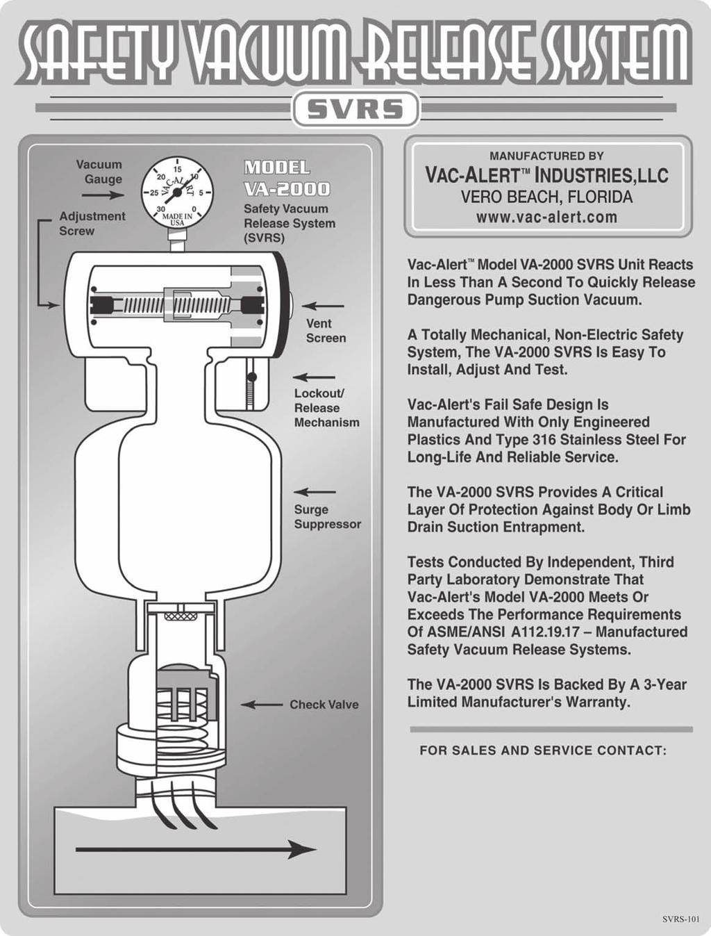
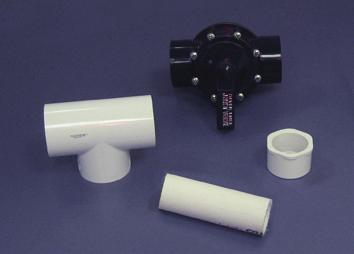
2 1 o VAC-ALERT MODEL VA-2000L (Lift) The Vac-Alert TM Model VA-2000L is a Safety Vacuum Release System (SVRS) designed for suction lift applications. Suction lift in this case applies to all applications where the circulating pump suction is no more than 24 below, or no more than 42 above the level of the pool or spa water surface. This unit incorporates a diameter orifice opening installed below the surge tube section. This orifice opening is sized to prevent nuisance tripping of the SVRS unit caused by high vacuum surges typical of many pump start-up conditions. The Model VA-2000L SVRS unit also utilizes a check valve assembly equipped with a 3.5 pound spring, a poppet disc and a one-way (up only) vented poppet. This check valve assembly permits continued water flow to the circulating pump while the SVRS unit is in the open or vented position. The 3.5 pound spring further compressed by the poppet disc, creates enough sealing force within the check valve to allow partial water flow to the circulating pump for suction lifts up to 3.5 feet. This is critical to the elimination of circulating pump damage that can be caused by a sustained dry-running condition. The one-way vented poppet allows the surge chamber to be internally recharged when the circulating pump is turned off. o VAC-ALERT MODEL VA-2000S (Submerged) The Vac-Alert TM Model VA-2000S is a Safety Vacuum Release System (SVRS) designed for submerged suction applications. Submerged suction in this case applies to all applications where the circulating pump suction is more than 24 below the level of the pool water surface. The Model VA-2000S is recommended on commercial pool applications where the pump has a submerged or flooded suction and runs 24/7. In submerged suction applications, for pumps 10 horsepower and greater, or for pumps located 10 or more below the water line, a pump shut-off switch (Model PSAC) is recommended. The Model VA-2000S unit incorporates a diameter orifice opening installed below the surge tube section. This orifice opening is sized to provide a limited amount of pump start-up surge protection, while at the same time allowing enough air into the piping system to insure dissipation of the dynamic suction force caused by the circulating pump. The Model VA-2000S SVRS unit also utilizes a check valve assembly equipped with a 0.25 pound spring and a non-vented poppet (no poppet disc or hole through the poppet). This check valve assembly utilizes a light duty spring to minimize the sealing force of the check valve. The non-vented poppet insures that water from the circulating system, under a positive hydrostatic head condition, does not migrate up into the SVRS unit. NOTE: The Model VA-2000 type is indicated on the outside of the box and on the unit itself. Make sure you have the correct Model SVRS for your application! SVRS in these instructions refers specifically to the Vac-Alert TM Model VA-2000.
3 2 3 Vac-Alert TM Industries, LLC Model VA-2000 Installation Instructions INTRODUCTION INITIAL SYSTEM PREPARATION Determine whether the installation requires a VA-2000L (suction lift) or a VA-2000S (submerged or flooded suction) SVRS unit. See the preceding page for a more detailed description of each SVRS type. For commercial installations where the circulating pump has a submerged or flooded suction and runs continuously (24/7), the Model VA-2000S is recommended. For submerged or flooded suction installations where the circulating pump is 10 HP or greater, or the pump is located 10 feet or more below the pool or spa water surface, in addition to the installation of a Model VA-2000S unit, a pump shut-off switch (Model PSAC) is recommended. Contact your Vac-Alert TM representative for details on the Model PSAC. The Model VA-2000L is designed for use in installations where a timer or air switch is used to automatically cycle the circulation pump. The VA-2000L unit is to be applied in these applications where the pump is located no more than 24 below, or no more than 42 above the level of the pool or spa water surface. For applications where the pump is located more than 42 above pool or spa water level, contact your Vac-Alert TM representative for further instructions. For applications where the pump is located more than 24 below pool or spa water level, use the VA-2000S SVRS unit. The SVRS unit should be installed on the main drain line. It is not recommended that the SVRS unit be installed on the common header or common line to the pump, where additional skimmer line(s) or vacuum line(s) are also present. The SVRS is designed to protect against main drain suction entrapment, and the unit should be adjusted to the specific hydraulics of the main drain line. Before installing the SVRS unit, check system vacuum level at the pump with all flow diverted from the main drain suction line, i.e. shut-off all other water sources except the main drain suction line. If the main drain line is plumbed through a skimmer, the skimmer will have to be blocked to insure all flow is routed from the main drain. Using a vacuum gauge at the pump, note the level of the operating vacuum. If the vacuum level exceeds 15 Hg, system adjustments to lower the vacuum level will assist with the proper installation of the SVRS unit.
4 3 Following are suggestions for lowering system operating vacuum levels at an existing pool or spa. 1. Reduce the pump size or reduce the pump impeller diameter 2. Check the main drain line for blockages 3. Replace the drain cover with another cover that has a higher open area 4. Replace return side nozzles with smaller orifices to slow down flow For new construction or a remodel project, increase the diameter of the connector piping and fittings where two or more main drains are employed, and increase the diameter of the main drain suction line to reduce pipe velocity and running vacuum level. Minimize the use of 90 degree elbows and other fittings that increase the system pressure drop. Keep your pipe runs as short as possible. Once the system vacuum level is set at 15 Hg or less, the system can be prepared for SVRS installation. SVRS INSTALL REQUIREMENTS Though the SVRS (Safety Vacuum Release System) is easily installed, Vac-Alert TM highly recommends that a licensed contractor or service company install the SVRS. When you properly install a Vac-Alert TM SVRS, you are providing an important layer of protection against dangerous body and limb entrapment situations. This system is not an effective defense against hair entanglement. This device may mitigate evisceration. The Model VA-2000 SVRS unit shall only be installed in conjunction with an ASME/ANSI A or VGB 2008 approved suction fitting(s), or an approved channel drain system at each suction outlet or drain outlet. For newly constructed pools or spas where two or more suction outlets are employed, it is important that the outlets be separated by three feet, with correctly sized diameter connector piping and fittings, to keep connector pipe velocity less than 3 feet per second when all suction outlets are flowing. No special tools to install the Vac-Alert TM SVRS are required. Here is what you need: 1. Portable drill with 1 or 1-1/4 hole saw type bit (if installing a snap or clamp-on tee) 2. Hacksaw or PVC pipe cutter 3. Flat bladed screwdriver 4. Small level (used to ensure vertical, level installation of the SVRS unit) 5. PVC primer and glue (medium body suitable for wet or dry field conditions) 6. 6 length of 1-1/2 diameter Schedule 40 PVC pipe (vertical section of pipe installed between SVRS and tee, or SVRS and elbow). 7. Schedule 40 PVC tee fitting (size of suction line) 8. Full-port ball valve, slide gate or butterfly valve, or pole-mounted test mat 9. Standard Schedule 40 PVC fittings necessary to adapt the SVRS to existing piping 10. Vacuum Gauge*
5 4 Begin by checking the vacuum levels at each pump. Close off all other secondary lines and check the vacuum level with all flow coming from the main drain line. If the vacuum level is over 15, see previous suggestions for lowering system running vacuum level. NOTE: Do not use a flow restricted test valve, or a slow acting test valve such as a gate, globe or diaphragm type valve. Use only full-port, fast-acting test valves such as a two-way valve, ball valve, or butterfly valve. A test valve may not be required if the SVRS can be mat tested. Use only a pole-mounted test mat for mat testing of Vac-Alert TM SVRS units. It is recommended that a test valve be installed to facilitate testing and inspection. A test valve may be required by local inspection authorities. Determine the number of pumps and main drain suction lines to be protected. You will need to install a Vac-Alert TM SVRS for each pump plumbed to a dedicated main drain suction line. See enclosed installation diagrams. One Vac-Alert TM SVRS unit can be used on a pool / spa combination where a single circulation pump is employed. In this case the SVRS is located on the common main drain line for both the pool and spa (see installation diagrams). The SVRS can handle a difference of no more than 6 Hg between the operating vacuum level in pool mode, and the operating vacuum level in spa mode. System adjustments may be necessary to insure the two running vacuum levels don t differ more than 6 Hg. Next, determine the size of the main drain suction piping. Determine the Schedule 40 PVC fittings you will need to adapt the 1-1/2 diameter SVRS connection to the existing piping. The SVRS must be mounted in the vertical position. Some installations may require a Schedule 40 PVC reducing bushing, elbow, and pipe nipples to complete the SVRS installation. Turn off all pump motors and select the best location for SVRS installation. SVRS LOCATION 1. Locate the SVRS on the main drain suction line, between the main drain and the main drain line isolation valve. Install the SVRS at least 12 away from the pump suction. Do not close-couple the SVRS to the pump suction. For new construction installations, the SVRS should be located 18 to 60 from the pump suction on the main drain line. For retrofit installations, the SVRS should be installed no closer than 12 from the pump suction, and within 60 of the pump suction inlet whenever possible. See enclosed installation diagrams for further details. 2. Find a six to twelve inch section of pipe where the SVRS can be installed. This location can be either a vertical or horizontal section of pipe. Locate and orient the SVRS away from other valves and high traffic areas. The SVRS can face any direction, but must be installed vertical and level.
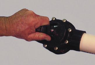
6 5 SVRS INSTALLATION 1. Install a tee fitting at the optimum horizontal section of pipe location. If a vertical section of pipe is the only option it will require an elbow be used to mount the SVRS off the installed tee. A reducing bushing may also be required to mate the 1-1/2 diameter SVRS to the tee fitting installed. Utilize pipe nipples to join fittings in a close-coupled fashion, as required. Note: A 6 long, 1-1/2 diameter, vertical section of Schedule 40 PVC pipe is to be installed between the SVRS and tee, or the SVRS and elbow. The 6 vertical pipe section has no bearing on SVRS operation, but is recommended in the event the SVRS unit must be removed or relocated in the future. 2. Install a full port, fast acting test valve (two-way, ball or butterfly) in the main drain suction line before the tee fitting for the SVRS unit. The test valve should be installed in the main drain suction line between the main drain and the SVRS, within two feet of the Vac-Alert TM unit for ease in testing. A test valve need not be installed if the SVRS is to be mat tested at the main drain. Where hydrostatic valve(s) are present in the circulation system, then the Vac- Alert TM should be mat tested at the main drain at least three times after installation. 3. For existing installations, when a snap tee or clamp-on tee is installed, after the fittings have dried, use a battery-operated hand drill to drill a 1 or 1-1/4 hole in the suction piping. 4. Install the SVRS unit on the 6 long, 1-1/2 diameter vertical pipe section, and let all glue joints dry before proceeding to Pump Start-Up Test. PUMP START-UP TEST 1. At this point, the pump start-up vacuum level for the system needs to be determined. Close the SVRS vent by pushing down on the reset lever. Use the vacuum gauge on the installed SVRS unit to read the pump start-up vacuum level in the main drain line. The peak start-up vacuum level should be read with full prime on the pump, at maximum return rate of flow, with all suction flow directed from the main drain. This condition will typically produce the peak vacuum level that the SVRS will be exposed to during pump start-up. Set valves and equipment to the above conditions, and! Turn on the pump. Observe the SVRS response. Make sure to notice the peak vacuum level on the SVRS vacuum gauge. If the peak vacuum level exceeds 10 Hg, the SVRS will either leak air into the system or lock open (See Item 2. below).
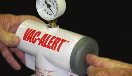
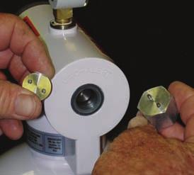
7 6 The Vac-Alert TM SVRS unit is designed for systems that operate at vacuum levels less than 15 Hg. Do not install a Vac-Alert TM SVRS unit on any system that operates at a vacuum level above 15 Hg. See Initial System Preparation for options on how to lower system operating vacuum level. 2. NOTE: Each SVRS comes factory set to remain closed (non-venting) for vacuum levels up to 10 Hg.! If the pump start-up test indicates a vacuum level above 10 Hg, the SVRS will either leak air into the system momentarily, and then re-seal, or the SVRS may lock open in the venting position. Given a start-up vacuum in excess of 10 Hg, or the SVRS is allowing too much air to leak into the system, the SVRS will need adjustment for site-specific vacuum levels.! If the pump start-up test indicates a vacuum level of less than 10 Hg, and the SVRS is not leaking air into the system, the SVRS should not need any further adjustment. SVRS ADJUSTMENT The SVRS is field adjustable for vacuum levels from 0 Hg to 15 Hg. As previously stated each unit is shipped from the factory set at about 10 Hg. To adjust the Vac-Alert TM unit for site-specific vacuum conditions proceed as follows: 1. NOTE -Before making any adjustment to the SVRS spring compression screw, make sure the pump is turned off and the Vac-Alert TM unit is in the open (venting) position. The SVRS can be placed in the open position from the vent end (gray end) by utilizing a screwdriver. Remove the vent screen and place the screwdriver in the hole at the vent end. Push the Vac-Alert TM piston towards the adjustment end until the lockout mechanism is engaged. A clicking sound is heard when the lockout mechanism is engaged. 2. Remove the security cap from the adjustment end (white end with Vac-Alert TM embossing on body) utilizing the spanner tool shipped with the unit. The security cap is removed by unthreading it, rotating in a counterclockwise direction. Once the security cap is removed, the spring compression adjustment screw is visible inside the Vac-Alert TM body. To adjust this screw, a flat bladed (straight slot) screwdriver is required. 3. With the Vac-Alert TM in the open position, turn the adjustment screw clockwise to increase spring compression (for higher vacuum operating levels), and counterclockwise to decrease spring compression (for lower vacuum operating levels).! To adjust the Vac-Alert TM for an operating vacuum level of less than 5 Hg, rotate the adjustment screw counterclockwise until the screw travel stop (minimum spring compression setting) is reached.
8 7! To adjust the SVRS unit for an operating vacuum level of up to 15 Hg, rotate the adjustment screw clockwise until the screw travel stop (maximum spring compression setting) is reached, then back the adjustment screw off counter-clockwise one revolution.! The adjustment screw must be positioned properly between the two travel stops to set the Vac-Alert TM unit for operating vacuum levels greater than 5 Hg and less than 15 Hg. NOTE: Always adjust the Vac-Alert TM adjustment screw with the unit in the open (venting) position. The SVRS can be placed in the open position from the vent end (gray end) by utilizing a screwdriver. Remove the vent screen and place the screwdriver in the hole at the vent end. Push the Vac-Alert TM piston towards the adjustment end until the lockout mechanism is engaged. A clicking sound is heard when the lockout mechanism is engaged. Once screw adjustment is made, the SVRS can be returned to the closed (non-venting) position by gently pressing down on the reset lever. FINAL ADJUSTMENT 1. The Vac-Alert TM should be adjusted to a spring compression level that ensures the SVRS unit does not lock open during pump start-up. Do not over tighten the adjustment screw. Adjust the screw in increments of two full rotations, then reset the unit, and retest for air venting. The SVRS should be tested at various adjustment levels to determine the balance point at which venting begins to occur at pump start-up. 2. Once the balance point is determined, the adjustment screw should be positioned clockwise two (2) full turns beyond this point as the final SVRS setting. SVRS TESTING With the pump turned on, fully primed and with suction piping valves set to divert all flow from the main drain ( turn off skimmers and all other ports of suction except the main drain line). 1. Quickly close the test valve to simulate a main drain blockage. A pole-mounted test mat can also be used to cover the main drain to simulate the same effect. 2. The Vac-Alert TM SVRS should respond instantly to the simulated blockage. The SVRS should lock in the open position, venting air into the system and dissipating the suction vacuum. A near zero reading on the SVRS vacuum gauge confirms the system is operating properly. 3. Open the test valve or remove the test mat from the main drain, and reset the SVRS unit by gently pressing down on the reset lever. With the pump turned on and fully primed, once again simulate the main drain blockage as done in the previous test. The SVRS should respond as before. Repeat this test procedure at least three (3) times to confirm proper operation of the Vac-Alert TM SVRS unit.
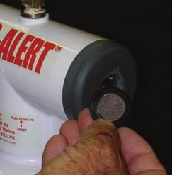
9 8 FINAL INSTRUCTIONS Important Note: The Vac-Alert TM Model VA-2000L (Lift) SVRS unit is designed to protect against dry running of self-priming pumps where pump suction lift is less than (3.5) feet. To make sure the unit is working properly, turn off the pump and place the Vac-Alert TM SVRS unit in the open (venting) position. Wait one minute, then turn the pump on and make sure the pump partially re-primes. Note that partial re-priming may take several minutes for some systems. Once partial re-prime is established, make sure there is a noticeable stream of mixed air/water flow through the pump returning to the pool or spa. For suction lifts over (3.5) feet, or suction lift conditions where partial re-priming does not occur, even after several minutes of pump running time, call Vac-Alert TM Customer Service for further instructions. Reset the SVRS unit to the closed (non-venting) position before returning the system to normal operation. The Vac-Alert TM SVRS unit is provided with a vent screen and an adjustment screw security cap. These must both be installed and properly tightened to complete the installation. It is critical that both of these covers be in place to ensure ongoing safe operation of the SVRS unit.! The security cap is threaded into place utilizing the spanner tool provided with the unit.! The vent screen is installed with a press fit covering the vent hole on the vent end (gray end) of the SVRS unit. The vent screen should be pushed into place so that the vent screen flange is flush to the vent end (gray end) surface. A screwdriver can be used to press this screen into final position. Care must be taken to avoid bending or crushing the vent screen. Each SVRS unit is provided with a Vac-Alert TM Field Test Data Sheet that must be completed. Fill out this form and fax or mail it to Vac-Alert TM Industries as instructed on the form. It is critical that this form be completed and all of the information requested supplied. The Vac-Alert TM SVRS must be routinely tested to ensure ongoing safe operation of the unit. It is required that the SVRS be tested, per the prescribed testing procedures, prior to the start of each swimming season, and recommended thereafter at least once per month while the pool or spa remains in use by the end user.
10 9 IMPORTANT NOTICES INSTALLER AND USER MUST READ! 1. Locate the Vac-Alert TM SVRS on the main drain suction line. The SVRS must be mounted in the vertical position. All SVRS units shall be field adjusted to site-specific hydraulic conditions. Once adjusted the SVRS unit must be tested three times by simulating an entrapment event. 2. Use a fast acting, full-flow, full-port two-way valve, ball valve or butterfly valve, installed within two feet of the SVRS unit, as a test valve. A test valve is an optional alternative to a pole-mounted test mat. Each Vac-Alert TM SVRS unit must be tested three (3) times to ensure proper adjustment and operation. 3. This SVRS unit must be routinely tested. The Vac-Alert TM SVRS unit must be tested at the start of each swimming season, and recommended thereafter at least once per month while the pool or spa remains in use by the end user. 4. For multiple pump systems, one (1) Vac-Alert TM SVRS unit is required for each pump plumbed to a dedicated main drain suction line. 5. The Vac-Alert TM SVRS unit is rated for suction vacuum levels up to 15 inches of Hg (mercury). For vacuum levels above 15 inches of Hg, see Initial System Preparation instructions for recommendations on how to lower system operating vacuum level. 6. WARNING: Check valves and obstructions located between the main drain(s) and the Vac-Alert TM SVRS must be removed from the suction system. Do not install (must be removed from existing systems) a check valve in a main drain line between the main drain(s) and the SVRS. A check valve may be installed in the main drain suction line between the SVRS connection tee and the circulation pump. Also, check valves may be installed anywhere on the return side of the pump. The Vac-Alert TM SVRS may be used with hydro-static valves, but a mat test of the SVRS operation is recommended. 7. This product, when installed in accordance with manufacturer s instructions, is designed to protect against injury caused by body or limb entrapment. This device is not designed for protection against hair entanglement. It may mitigate evisceration. The Model VA-2000 must be installed in conjunction with an ASME/ANSI A or VGB 2008 approved suction fitting(s), or an approved channel drain system at each suction outlet or drain outlet. 8. Tests conducted by independent, third part laboratory demonstrate that Vac-Alert s Model VA-2000 meets or exceeds the performance requirements of ASME/ANSI A and ASTM standard F2387 Manufactured Safety Vacuum Release Systems.
11 10 11 SVRS USE AND MAINTENANCE: 1. To use the Vac-Alert TM Model VA-2000 properly, and to maintain the unit in good working order, the following should be practiced. a. Make sure that the vent screen is always in place and is clear of all obstructions or debris. This is critical to ensure that the air vent passageway is kept clear to allow the movement of air into the pump suction piping, in the event of a high vacuum occurrence due to a main drain blockage. b. Using the installed test valve, or a pole-mounted test mat, conduct routine testing of the SVRS device to ensure proper adjustment of the unit. The Vac-Alert TM Model VA-2000 SVRS unit must be tested at the start of each swimming season, and recommended thereafter at least once per month while the pool or spa remains in use by the end user. c. If the SVRS does not function properly during a routine test, the device may need further adjustment. Refer to SVRS adjustment procedures detailed herein, and follow these procedures to re-adjust the SVRS unit. Test the SVRS unit three (3) times after re-adjustment to ensure proper SVRS operation. Should the SVRS unit still not operate properly, immediately shut down the pool or spa, and call your local pool/spa professional, or call Vac-Alert TM Customer Service for referral to your nearest dealer. d. Make sure the security cap is always installed to guard against unauthorized tampering with SVRS adjustment. 2. The SVRS unit requires no lubrication, no oil, and no grease for proper operation. Do not apply any oil, grease or lubricant, on or in this SVRS device. Do not obstruct the vent screen on the SVRS unit with any foreign material, such as paint or aerosol sprays. 3. The Model VA-2000 SVRS unit is supplied with the following parts that may need replacement over time depending upon environmental exposure and use: a. Vacuum Gauge (0 to 30 Hg)......VA-2680 b. Adjustment Screw Security Cap. VA-2900 c. Security Cap Key (Hexagonal Spanner Tool). VA-2970 d. End Cap Vent Screen..VA-2850 e. Check Valve Spring (Suction 3.5 lb).. VA f. Check Valve Spring (Submerged 0.25 lb)... VA-2320S-.25 g. Check Valve Poppet (Suction Lift Vented)... VA-2870L-P h. Check Valve Poppet (Submerged Suction Non-Vented)......VA-2875S-P To order any of the above parts, call your local pool service company, or call Vac-Alert TM Customer Service for referral to your nearest dealer.
12 11 4. The Model VA-2000 SVRS unit should always operate in a dry state. Any indication that the unit is flooded or water logged, as evidenced by water leakage from the SVRS unit, requires immediate service attention. Immediately shut down the pool or spa, and call your local licensed service company, or call Vac-Alert TM Customer Service for referral to your nearest dealer. 5. The Model VA-2000 meets or exceeds the twelve hour -40 F & +140 F temperature performance testing set by the ASME/ANSI A Standard for Manufacturing Safety Vacuum Release Systems. We strongly suggest that the VA-2000 not be left in below freezing temperatures where the circulation system is not continually running or not protected by a pump house. In such cases, condensation could freeze piping and ice may impair or disable the safety features of the VA For installations that require winterization, the Model VA-2000 should be removed and stored, and then reinstalled upon system start-up. FOR CUSTOMER SERVICE IN FLORIDA & U.S. EAST COAST CALL: FOR CUSTOMER SERVICE IN ALL OTHER U.S. AREAS CALL: Dated: March 15, 2009
13
14 SVRS-101
15 14

16 m m m m m m m
17
18 VAC-ALERT FIELD VA-2000 INSTALLATION DATA SHEET A copy of this installation form MUST be mailed or faxed to Vac-Alert Industries, LLC within 10 days of installation to maintain all product warranty. Mail to: Vac-Alert Industries, 2455 Bennett Valley Rd., Santa Rosa, CA or fax to (707) SVRS INFORMATION A. Valve ARL serial number: B. Installation performed on: Pool( ) Spa( ) Fountain( ) Other( ) C. Did pool or spa have multiple main drains? Yes( ) No( ) D. Did valve trip three consecutive times? Yes( ) No( ) INSTALLATION LOCATION INFORMATION Name of Purchaser: Installation Address: I have discussed with the owner and/or individual the complete operational and testing procedure for the SVRS unit Installation Performed By: Date of Installation: Note: Although the SVRS is easily installed, we at Vac-Alert do highly recommend that the unit be installed by a Licensed Pool Service Company or an Authorized Service Technician (where State required). This SVRS does not offer protection from hair entrapment. Please be sure to install recognized antientrapment drain covers. Rev 1.06
19 VAC-ALERT INDUSTRIES, LLC ASSURANCE OF QUALITY Dear Vac-Alert Safety System Owner, Your new Vac-Alert System has passed a rigorous quality control procedure and is in conformance with the ASME/ANSI A and ASTM F2387 standards for manufactured Safety Vacuum Release Systems (SVRS). If you feel this unit is defective or damaged due to shipping or handling, it is your obligation to call: and speak to our technical support staff to answer any questions you may have. This system requires NO lubrication whatsoever. Lubricating this unit may cause failure and will void warranty. Vac-Alert assumes no liability or responsibility implied or otherwise if this system is lubricated. We highly recommend the use of an ASME/ANSI A approved main drain cover in conjunction with this system. This system is not an effective defense against hair entanglement. This devise may mitigate evisceration. Under no circumstances should any child ever be left unattended at or by any body of water. Never sit, lay or swim near or by suction ports, suction fittings or main drains. THIS PRODUCT IS 3RD PARTY TESTED TO CONFORM TO ASME/ANSI A AND ASTM F2387 STANDARDS Date of Installation This unit is warranted free of defects for a period of three years. This warranty applies to original purchaser only. This unit will be repaired or replaced at the discretion of Vac-Alert Industries, LLC, provided it is returned to the Manufacturer Freight-Prepaid. Please keep this document with your other important papers Vac-Alert Industries assumes no liability or responsibility if this unit is installed improperly or altered. We recommend this system be installed by a pool/spa professional. Installed by: Date: Installer ID( if applicable) Vac-Alert Unit Serial # Vac-Alert Industries, LLC (toll free) (fax)
Vac-Alert TM Industries, LLC
 Safety Vacuum Release System Installation Instructions Model VA-2000 Vac-Alert TM Industries, LLC 4505 Prosperity Drive Fort Pierce, FL 34981 www.vac-alert.com October 30, 2007 2 o VAC-ALERT MODEL VA-2000L
SAFETY VACUUM RELEASE SYSTEM (SVRS)
") SAFETY VACUUM RELEASE SYSTEM (SVRS) FOR EXISTING DEBRIS CANISTER APPLICATIONS INSTALLATION MANUAL MADE IN USA Safety compliant according to the Virginia Graeme Baker Pool and Spa Safety Act ASME A112.19.17-2010
SAFETY VACUUM RELEASE SYSTEM (SVRS) FOR EXISTING DEBRIS CANISTER APPLICATIONS INSTALLATION MANUAL MADE IN USA Safety compliant according to the Virginia Graeme Baker Pool and Spa Safety Act ASME A112.19.17-2010
CONTENTS CONSIDERATIONS. General Plumbing Component Connection ILLUSTRATION. Control System CONFIGURATION. Voltage Verification CONNECTION
 AIR SERIES SYSTEM INSTALLATION MANUAL CONTENTS CONSIDERATIONS General Plumbing Component Connection 2 2 2 ILLUSTRATION Control System 3 CONFIGURATION Voltage Verification 4 CONNECTION Component Connection
MDX² INSTALLATION MANUAL
 ANTI-ENTRAPMENT DEBRIS DRAIN MDX² INSTALLATION MANUAL CONCRETE POOLS SUBMERGED SUCTION OUTLET FOR MULTIPLE DRAIN USE FOR USE ON FLOOR SEE SPECIAL INSTRUCTIONS FOR CALIFORNIA AND FLORIDA ON PAGES 4 AND
STOP. SAFETY INFORMATION Please read and understand this entire manual before attempting to assemble, operate or install the product.
 STOP Power supply required Questions, problems, missing parts? Before returning to your retailer, call our customer service department at 1-800-742-5044, 7:30 a.m. - 5 p.m., EST, Monday - Friday. 115 volts
INSTALLATION MANUAL. G&F Manufacturing 7902 Interstate Court North Fort Myers, Florida
 INSTALLATION MANUAL G&F Manufacturing 7902 Interstate Court North Fort Myers, Florida Heat Pump Services 990 NW 53rd Street Fort Lauderdale, Florida 33309 G&F Manufacturing 7902 Interstate Court North
WALLACE MAXIPUMP 3000, 5000, 6000 and HYDROJET 30P, 30C, 140 AND HJ400 INSTALLATION AND MAINTENANCE INSTRUCTIONS
 6 th June 2006 Page 1 WALLACE MAXIPUMP 3000, 5000, 6000 and HYDROJET 30P, 30C, 140 AND HJ400 INSTALLATION AND MAINTENANCE INSTRUCTIONS Please read and follow all these instructions carefully before proceeding
Arch Feeder: Installation Manual
 Arch Feeder: Installation Manual Model #A300N Arch Chemicals, Inc. 1200 Lower River Road, P.O. Box 800 Charleston, TN 37310-0800 Product Stewardship MAKING THE WORLD A BETTER PLACE Arch is committed to
INSTRUCTIONS FOR USE PORTABLE VACUUM SYSTEM LEI Part # s / , , , IMPORTANT INFORMATION
 INSTRUCTIONS FOR USE PORTABLE VACUUM SYSTEM LEI Part # s / 27-009, 27-010, 27-015, 27-020 IMPORTANT INFORMATION UNATHORIZED CHANGES OR ALTERATIONS TO ANY LINCOLN PORTABLE VACUUM SYSTEM WILL AUTOMATICALLY
SWIMMING POOL & SPA HEAT PUMPS OWNERS OPERATIONAL MANUAL
 SWIMMING POOL & SPA HEAT PUMPS OWNERS OPERATIONAL MANUAL MODEL AT105 AT115 AT130 with Titanium Heat Exchanger 2213 Andrea Lane Ft. Myers FL 33912 888-297-3826 941-482-0606 www.aquathermheatpumps.com DIGITAL
G&F Manufacturing Service Manual Version 2.0 April 2010
 G&F Manufacturing Service Manual Version 2.0 April 2010 Any tech working on these units must read this manual. Any questions, please call service department from the job site. 954-318-6900 Table of Content
Concept S-2. Indoor Infrared Stove Heater. RedCore Stove Heater
 Concept S-2 Indoor Infrared Stove Heater RedCore Stove Heater 2011-04-20 CUSTOMER SUPPORT DO NOT RETURN THIS PRODUCT TO THE STORE WHERE YOU BOUGHT IT FOR IMMEDIATE CUSTOMER SERVICE, PLEASE CALL: 888-4BGT
HIGH PERFORMANCE PUMP
 WHISPERFLOXF HIGH PERFORMANCE PUMP INSTALLATION AND USER S GUIDE IMPORTANT SAFETY INSTRUCTIONS READ AND FOLLOW ALL INSTRUCTIONS SAVE THESE INSTRUCTIONS P/N L300203 B1012 i CUSTOMER SERVICE / TECHNICAL
CHAMPION PUMP OWNER S MANUAL
 CHAMPION PUMP OWNER S MANUAL IMPORTANT SAFETY INSTRUCTIONS READ AND FOLLOW ALL INSTRUCTIONS SAVE THESE INSTRUCTIONS WARNING: Before installing this product, read and follow all warning notices and instructions
HARMSCO INSTALLATION AND OPERATION MANUAL UPFLOW SWIMMING POOL CARTRIDGE FILTER CARTRIDGE CLEANING INSTRUCTIONS HARMSCO CARTRIDGES
 HARMSCO INSTALLATION AND OPERATION MANUAL UPFLOW SWIMMING POOL CARTRIDGE FILTER CARTRIDGE CLEANING INSTRUCTIONS HARMSCO CARTRIDGES May be cleaned and reused before replacement is necessary. Cartridge cleaning
UNIVERSAL TEE STYLE Hydromassage Bath Heater INSTALLATION INSTRUCTIONS
 UNIVERSAL TEE STYLE Hydromassage Bath Heater INSTALLATION INSTRUCTIONS This Manual Covers: 7 Models SG100-15UP - 120V, 1500W SG202-20UP - 240V, 2000W CARTON CONTENTS: A - One (1) Whirlpool Bath Heater
The Danger signal indicates an immediately hazardous situation which, if not avoided, will result in death or serious injury.
 The Danger signal indicates an immediately hazardous situation which, if not avoided, will result in death or serious injury. The Warning signal alerts you to potential hazards or unsafe practices which,
POWER VENTER SYSTEM. Model: PVO-300, PVO-600
 POWER VENTER SYSTEM Model: PVO-300, PVO-600 Included is one ETL and cetl listed Power Venter to be used primarily with a single 120VAC controlled oil fired furnace, boiler, or water heater. The PVO may
569, 570, 571, 572 Series
 Please read and save this Repair Parts Manual. Read this manual and the General Operating Instructions carefully before attempting to assemble, install, operate or maintain the product described. Protect
Eldex Column Heater. Operator s Manual
 Eldex Eldex Column Heater Operator s Manual Eldex Laboratories, Inc. 30 Executive Court Napa, CA 94558 Tel: (707) 224-8800 Fax: (707) 224-0688 www.eldex.com Rev. B: 081700 2000Eldex Laboratories, Inc.
568X, 587X, 588X Series
 Please read and save this Repair Parts Manual. Read this manual and the General Operating Instructions carefully before attempting to assemble, install, operate or maintain the product described. Protect
ELITE (110V) (220V)
 (220V)") Rev 1B 1-28-2014 USER'S MANUAL 1 ELITE 20-5061-00 (110V) 20-5066-00 (220V) 8000 South Kolb Road Tucson, AZ 85756 Phone 800 528 1597 Fax 520885 1189 www.wellsgrp.com Email: sales@wellsgrp.com Table Of Contents
Rev 1B 1-28-2014 USER'S MANUAL 1 ELITE 20-5061-00 (110V) 20-5066-00 (220V) 8000 South Kolb Road Tucson, AZ 85756 Phone 800 528 1597 Fax 520885 1189 www.wellsgrp.com Email: sales@wellsgrp.com Table Of Contents
OPERATION AND MAINTENANCE MANUAL ELC-810 AUTOMATIC WATER LEVEL CONTROLLER. AquatiControl Technology
 OPERATION AND MAINTENANCE MANUAL ELC-810 AUTOMATIC WATER LEVEL CONTROLLER AquatiControl Technology 3820 South Federal Blvd Sheridan, Colorado 80110 Toll Free: 877.755.8817 Fax: 303.761.1499 www.aquaticontrol.com
Model H1011.8/H1011.8HPS Water Cooler
 455 Kleppe Lane Sparks, NV 8943-6467 (775) 359-472 Fax (775) 359-7424 E-mail: haws@hawsco.com website: www.hawsco.com Model H0.8/H0.8HPS Water Cooler INSTALLATION, OPERATION & MAINTENANCE INSTRUCTIONS
HIGH PERFORMANCE POOL & SPA PUMPS
 HIGH PERFORMANCE POOL & SPA PUMPS INSTALLATION AND OPERATION MANUAL PREMIUM PR SERIES PR50F, PR75F, PR100F, PR125F, PR150F, PR200F Reltech Australia Pty Ltd 43-45 Kylta Rd West Heidelberg Vic 3081 Ph:
Getz Equipment Innovators 450 lb Dual Portable Dry Chemical Fill System
 Getz Equipment Innovators 450 lb Dual Portable Dry Chemical Fill System 1 Revised 11/18/10 2320 Lakecrest Drive, Pekin IL 61554 PH. (888) 747-4389 Fax (309) 495-0625 Website: www.getzequipment.com LIMITED
2 SPEED PUMP INSTRUCTION MANUAL READ THIS MANUAL CAREFULLY BEFORE USING YOUR 2 SPEED PUMP
 2 SPEED PUMP INSTRUCTION MANUAL READ THIS MANUAL CAREFULLY BEFORE USING YOUR 2 SPEED PUMP 8308 PUMP PARTS BREAKDOWN Ref # Part # Manf. # Descrip on 1 NEP2134 AC 81361 PUMP LID 2 NEP2135 AC 81396 PUMP LID
HIGH PERFORMANCE 3-PHASE PUMPS
 WHISPERFLOXF AND MAX-E-PROXF HIGH PERFORMANCE 3-PHASE PUMPS INSTALLATION AND USER S GUIDE IMPORTANT SAFETY INSTRUCTIONS READ AND FOLLOW ALL INSTRUCTIONS SAVE THESE INSTRUCTIONS i CUSTOMER SERVICE / TECHNICAL
569, 570, 571, 572 Series
 Please read and save this Repair Parts Manual. Read this manual and the General Operating Instructions carefully before attempting to assemble, install, operate or maintain the product described. Protect
TEMPERATURE CONTROLLERS
 Instruction Manual: H1 T-12 Thermostat PILOT GUARD INTRODUCTION: SCOPE: This instruction manual includes installation, operation, and parts information for the Kimray Thermostat and Pilot Guard. Refer
Owner s Manual READ AND SAVE THESE INSTRUCTIONS
 16 Outdoor Misting / Oscillating Fan Model Number: AMMF16R-1 Owner s Manual READ AND SAVE THESE INSTRUCTIONS CAUTION: Before using this product, read this manual and follow all safety rules and operating
ECONO FLO VSA 165 VARIABLE SPEED PUMP OWNER S MANUAL
 ECONO FLO VSA 165 VARIABLE SPEED PUMP OWNER S MANUAL IMPORTANT SAFETY INSTRUCTIONS READ AND FOLLOW ALL INSTRUCTIONS SAVE THESE INSTRUCTIONS WARNING: Before installing this product, read and follow all
WAILEA OWNER S MANUAL
 WAILEA OWNER S MANUAL The blades in each pack are matched for equal weight to assure smooth fan operation. If more than one fan is being installed, be careful not to mix blades from different cartons.
Installation Manual PS-225 & PS-275
 Installation Manual PS-225 & PS-275 Table of Contents Pre-Uncrating Checklist... 1 Verifying System Requirements... 2 Verifying System Direction... 2 Verifying the Electrical Requirements... 2 Removal
SANTA ROSA FIRE DEPARTMENT FIRE PREVENTION BUREAU PLAN REVIEW CHECKLIST
 July 1, 2010 SANTA ROSA FIRE DEPARTMENT FIRE PREVENTION BUREAU PLAN REVIEW CHECKLIST FIRE PUMP REVIEW Address: Permit #: Inspector: Date: Status: Inspector: Date: Status: A-Approved; AC-Approved w/comments;
SMF PUMP OWNER S MANUAL
 SMF PUMP OWNER S MANUAL IMPORTANT SAFETY INSTRUCTIONS READ AND FOLLOW ALL INSTRUCTIONS SAVE THESE INSTRUCTIONS WARNING: Before installing this product, read and follow all warning notices and instructions
QUIETFLO OWNER S MANUAL
 QUIETFLO OWNER S MANUAL INSTALLATION, OPERATION & PARTS To prevent potential injury and to avoid unnecessary service calls, read this manual carefully and completley. CAUTION - We highly recommend a qualified
Table of Contents What to Expect with Your Installation. Top Housing. Ceiling Plate. Tools Needed.
 Table of Contents Congratulations on purchasing your new Hunter ceiling fan! It will provide comfort and performance in your home or office for many years. This installation and operation manual contains
ECONO FLO 2.7HP VARIABLE SPEED PUMP OWNER S MANUAL
 ECONO FLO 2.7HP VARIABLE SPEED PUMP OWNER S MANUAL IMPORTANT SAFETY INSTRUCTIONS READ AND FOLLOW ALL INSTRUCTIONS SAVE THESE INSTRUCTIONS WARNING: Before installing this product, read and follow all warning
5) Do not start or stop the unit by inserting or pulling out the power plug.
 Do not start or stop the unit by inserting or pulling out the power plug.") 3058080 V170306 PURCHASE INFORMATION Thank you for choosing a Soleus Air Portable Air Conditioner. This Owner s Manual will provide you with valuable information necessary for the proper care and maintenance
3058080 V170306 PURCHASE INFORMATION Thank you for choosing a Soleus Air Portable Air Conditioner. This Owner s Manual will provide you with valuable information necessary for the proper care and maintenance
ProPet Washer. I-1020 Page 1 of 6 Rev. D /15/11
 ProPet Washer Overview The ProPet Washer incorporates up to 4 products with a rinse option to safely bathe animals. The different products are easily selected by the turn of a knob. Different dilution
DENVER PUBLIC SCHOOLS DESIGN AND CONSTRUCTION STANDARDS This Standard is for guidance only. SECTION PUMPS
 PART 0 A/E INSTRUCTIONS 0.01 Design Requirements A. Pumping system design 1. A primary-secondary pumping system is preferred. Redundant pipes are required for chillers and boilers. 2. Select pumps to operate
Series PX. Installation & Maintenance. Models: PX-3 PX-5 PX-7 1/2-HF PX-10-HF PX-15-HF. Materials: A - CPVC
 Series PX Installation & Maintenance Models: PX-3 PX-5 PX-7 /2-HF PX-0-HF PX-5-HF Materials: A - CPVC Introduction Penguin Pumps are designed to handle a large range of chemicals without difficulty. Completely
215 Gallon Waste Oil Tank With Bypass Regulator Installation Instructions
 215 Gallon Waste Oil Tank With Bypass Regulator Installation Instructions Lanair Products LLC 4109 Capital Circle Janesville, Wisconsin 53546 1-888-370-6531 www.lanair.com BEFORE YOU BEGIN INSTALLATION...
Installation and Operation Manual. ACF-18 Automatic Chlorinating Feeder
 Installation and Operation Manual ACF-18 Automatic Chlorinating Feeder Operating Specifications Inlet Flow: 1.0-1.5 gpm Outlet Flow: = Inlet Flow Inlet Pressure: 10-45 psi Maximum Output: 26 lbs. of Available
INSTALLATION INSTRUCTIONS
 INSTALLATION INSTRUCTIONS TM DishDrawer dishwasher DD36SDFTX (Designer) & DD36STI (Integrated) models US CA 59008D 04.3 a SAFETY AND WARNINGS Electrical hazard WARNING! Before installing the dishwasher,
THERMAL SYSTEMS, INC. Installation and Operation Manual
 THERMAL SYSTEMS, INC. Installation and Operation Manual Revised September 2016 1. GENERAL SAFETY INFORMATION 1.1 Specification Never exceed the maximum allowable temperature or pressure ratings. Never
INSTALLATION INSTRUCTIONS WARRANTY
 QT FLOW CENTER INSTALLATION INSTRUCTIONS Fig. 1. Low Head Pump Center Flow Chart Fig. 2. High Head Pump Center Flow Chart NOTE: Read the entire instruction manual before starting the installation. WARRANTY
Installation and Operation Manual For Hunter Ceiling Fans
 Installation and Operation Manual For Hunter Ceiling Fans 1 2 CONGRATULATIONS! Your new Hunter ceiling fan is an addition to your home or office that will provide comfort and performance for many years.
INSTALLATION INSTRUCTIONS
 INSTALLATION INSTRUCTIONS TM DishDrawer dishwasher DD4S 7 & DD4ST 7 models US CA 59004D 04.3 FOLLOW THE INSTALLATION SEQUENCE RELEVANT TO YOUR MODEL STANDARD HEIGHT SINGLE MODELS TALL HEIGHT SINGLE MODELS
Remote Water Quality System Standard Equipment (supplied by EPI) Remote Water Quality System Optional Equipment (supplied by EPI)
 Remote Water Quality System Optional Equipment (supplied by EPI)") Page 1 of 11 Parts List Remote Water Quality System Standard Equipment (supplied by EPI) 20sq ft Skimmer-Filter Remote Water Quality Plumbing Kit Heater-Controller Keypad Control 220V 3/4HP Circulation
Page 1 of 11 Parts List Remote Water Quality System Standard Equipment (supplied by EPI) 20sq ft Skimmer-Filter Remote Water Quality Plumbing Kit Heater-Controller Keypad Control 220V 3/4HP Circulation
WHEATGRASS JUICER C O M M E R C I A L. INSTRUCTION MANUAL Model No
 COMMERCIAL PRODUCTS ATTENTION If any components of this unit are broken, do not operate properly, or for product returns, please contact Pragotrade at 1-800-814-4895 Outside the U.S. call 440-638-3131.
installation and operation manual for Hunter Ceiling Fans
 For Your Records and Warranty Assistance Model Name: Catalog/Model No.: Serial No.: Date Purchased: Where Purchased: For reference also attach your receipt or a copy of your receipt to the manual. installation
NON-SUBMERSIBLE WATER PUMP
 NON-SUBMERSIBLE WATER PUMP MODEL NO: CEB103 PART NO: 7230327 OPERATION & MAINTENANCE INSTRUCTIONS LS0114 INTRODUCTION Thank you for purchasing this CLARKE Water Pump, which is a general purpose pump, suitable
J-PRO V 230V Dual Voltage Chlorinator Installation & Start-Up Guide
 J-PRO-22 110V 230V Dual Voltage Chlorinator Installation & Start-Up Guide Thank you for purchasing a Clean Water System! With proper installation and a little routine maintenance, your system will be providing
WKS 4000 SERIES (USA only) --INSTALLATION INSTRUCTIONS--
 --INSTALLATION INSTRUCTIONS--") 8610 Production Avenue San Diego, California 92121 (858) 566-7465 Fax (858) 566-1943 WKS 4000 SERIES (USA only) --INSTALLATION INSTRUCTIONS-- Thank you for choosing a BREEZAIRE cooling unit. We believe
8610 Production Avenue San Diego, California 92121 (858) 566-7465 Fax (858) 566-1943 WKS 4000 SERIES (USA only) --INSTALLATION INSTRUCTIONS-- Thank you for choosing a BREEZAIRE cooling unit. We believe
Owner s Guide and Installation Manual
 Tribeca Owner s Guide and Installation Manual English Form# M6000-01 20120416 2012 Casablanca Fan Co. Welcome Your new Casablanca ceiling fan is an addition to your home or office that will provide comfort
Elite Primer Baldor Series External Pond Pump
 Elite Primer Baldor Series External Pond Pump ( 5250PPB21, 6440PPB23, 7550PPB26, 9600PPB28) Installation and User s Guide IMPORTANT SAFETY INSTRUCTIONS, READ AND FOLLOW ALL INSTRUCTIONS. SAVE THESE INSTRUCTIONS
Hydrotherapy Jets (Remote Water Quality System)
") Page 1 of 6 Parts List (_) - 50 Roll of Flex PVC pipe 1-3/4 HP Circulating Centrifugal Pump 1 25 Roll of Flex PVC pipe 4-1 1 / 2 " Tees 2-1 1 / 2 " Ball Valves 2 - Female slip couplers 4-1/2" 90 degree
Page 1 of 6 Parts List (_) - 50 Roll of Flex PVC pipe 1-3/4 HP Circulating Centrifugal Pump 1 25 Roll of Flex PVC pipe 4-1 1 / 2 " Tees 2-1 1 / 2 " Ball Valves 2 - Female slip couplers 4-1/2" 90 degree
SECTION STEAM CONDENSATE PUMPS
 PART 1 - GENERAL 1.1 DESCRIPTION SECTION 23 22 23 STEAM CONDENSATE PUMPS SPEC WRITER NOTES: 1. Delete between // ---- // if not applicable to project. Also delete any other item or paragraph not applicable
MAXI PUMP INSTRUCTION MANUAL NE6151B /NE6171B READ THIS MANUAL CAREFULLY BEFORE USING YOUR MAXI PUMP
 MAXI PUMP INSTRUCTION MANUAL NE6151B /NE6171B READ THIS MANUAL CAREFULLY BEFORE USING YOUR MAXI PUMP 8104 MAXI-PUMP PARTS BREAKDOWN Re f # 1 2 3 4 5 6 7a 7b 8 9 10 11 12 13 14 15 16 2 Part # NEP2134 NEP2135
Installation Manual PS-200 & PS-201
 Installation Manual PS-200 & PS-201 Table of Contents Pre-Uncrating Checklist... 1 Verifying System Requirements... 2 Verifying System Direction... 2 Verifying the Electrical Requirements... 2 Removal
J-PRO V 230V Dual Voltage Hydrogen Peroxide Pump Installation & Start-Up Guide
 J-PRO-22 110V 230V Dual Voltage Hydrogen Peroxide Pump Installation & Start-Up Guide Thank you for purchasing a Clean Water System! With proper installation and a little routine maintenance, your system
SERVICE MANUAL. Bradford White ElectriFLEX HD (Heavy Duty) Commercial Electric Water Heater CEHD SERIES Immersion Thermostat Models
 Commercial Electric Water Heater CEHD SERIES Immersion Thermostat Models") Bradford White ElectriFLEX HD (Heavy Duty) Commercial Electric Water Heater CEHD SERIES Immersion Thermostat Models SERVICE MANUAL Troubleshooting Guide and Instructions for Service (To be performed ONLY
Bradford White ElectriFLEX HD (Heavy Duty) Commercial Electric Water Heater CEHD SERIES Immersion Thermostat Models SERVICE MANUAL Troubleshooting Guide and Instructions for Service (To be performed ONLY
Model OP155 Air Dryer
 "Teamwork & Communication" Model OP155 Air Dryer Operating Manual with Parts Identification OP155-INST June 15, 1998 Issue 2 GUSMER CORPORATION A Subsidiary of Gusmer Machinery Group, Inc. One Gusmer Drive
SEISCO SUPERCHARGER EXTENDER/BOOSTER INSTALLATION GUIDE & OWNERS MANUAL
 SEISCO SUPERCHARGER EXTENDER/BOOSTER INSTALLATION GUIDE & OWNERS MANUAL This manual is provided as a guide to installation. All installations must comply with any and all local and national electrical
Owner s Manual Refrigerated Compressed Air Dryer Model F-50
 Owner s Manual Refrigerated Compressed Air Dryer Model F-50 Read carefully before attempting to assemble, install, operate or maintain the product described. Protect yourself and others by observing all
Built-In Dishwasher. Installation Instructions. BEFORE YOU BEGIN Read these instructions completely and carefully. IMPORTANT The dishwasher MUST be
 Installation Instructions Built-In Dishwasher If you have questions, call 800.GE.CARES (800.432.2737) or visit our website at: www.ge.com BEFORE YOU BEGIN Read these instructions completely and carefully.
SPARUS 160 ENERGY EFFICIENT AQUACULTURE DUTY PUMP
 AQUATIC ECO-SYSTEMS SPARUS 160 ENERGY EFFICIENT AQUACULTURE DUTY PUMP INSTALLATION AND USER S GUIDE IMPORTANT SAFETY INSTRUCTIONS READ AND FOLLOW ALL INSTRUCTIONS SAVE THESE INSTRUCTIONS i CUSTOMER SERVICE
LIL SHARK TM AUTOMATIC POOL CLEANER. Model GW8000 OPERATION, TROUBLESHOOTING & PARTS. About Safety
 LIL SHARK TM AUTOMATIC POOL CLEANER O W N E R S M A N U A L Model GW8000 OPERATION, TROUBLESHOOTING & PARTS About Safety Before installing the cleaner, review and understand all warnings and safety information
Installation Guide & Owner s Manual
 Installation Guide & Owner s Manual Model V760 Direct-to-Drain Thermal Reduction System for Autoclave Wastewater Includes CSA-Certified VistaCheck Dual Check Backflow Preventer PATENT PENDING VistaCool
LC Series - Light Commercial Pump Station Installation and Operation Manual
 LC Series - Light Commercial Pump Station Installation and Operation Manual Please keep this manual with the pump station Content Rain Bird LC Series Overview... Safety Instruction... Operation... 3 Pump
installation and operation manual for Hunter Ceiling Fans
 For Your Records and Warranty Assistance Model Name: Catalog/Model No.: Serial No.: Date Purchased: Where Purchased: For reference also attach your receipt or a copy of your receipt to the manual. installation
OWNER S MANUAL INSTALLATION, OPERATION, & PARTS. Super Pump Series
 P/N: ISSPSERIES REV. A OWNER S MANUAL INSTALLATION, OPERATION, & PARTS *50HZ Models are not UL or CSA Listed. Super Pump Series The Hayward Super Pump TM is specifically engineered for the demanding requirements
Model No. GB-PAC-08E4. 8,000 BTU Portable Air Conditioner Operating Instructions
 Model No. GB-PAC-08E4 8,000 BTU Portable Air Conditioner Operating Instructions Thank you for choosing a Soleus Air Powered by Gree Portable Air Conditioner. This owner s manual will provide you with valuable
AC6 & AC8 HORIZONTAL SERIES Sealed Metallic Centrifugal Pumps Installation and Maintenance Instructions
 AC6 & AC8 HORIZONTAL SERIES Sealed Metallic Centrifugal Pumps Installation and Maintenance Instructions ASSEMBLY PUMPS WITH MOTORS 1. No assembly required. Unpack the pump and motor and examine for any
SEABREEZE. SeaBreeze Rain Shower System Model #1086-CH Owner's Manual
 SEABREEZE SeaBreeze Rain Shower System Model #1086-CH Owner's Manual SeaBreeze Model #1086 Please Read The Following Instructions COMPLETELY Before Beginning! Our goal is to ensure your installation goes
INSTALLATION INSTRUCTIONS
 INSTALLATION INSTRUCTIONS TM DishDrawer dishwasher DD4D 7 & DD4DT 7 models US CA 59004D 04.3 FOLLOW THE INSTALLATION SEQUENCE RELEVANT TO YOUR MODEL STANDARD HEIGHT DOUBLE MODELS TALL HEIGHT DOUBLE MODELS
DOUBLE DISHDRAWER TM DISHWASHER
 DOUBLE DISHDRAWER TM DISHWASHER DD4DDFT & DD4DVT models INSTALLATION GUIDE US CA 5985 A 08.7 SAFETY AND WARNINGS! WARNING! Electrical Shock Hazard Before installing the dishwasher, remove the house fuse
Electrical cable Water supply tube Fittings for tube Coupler Teflon tape. Hole saw min. 2½" bit
 Installation Parts and Tools Parts not Provided Electrical cable Water supply tube Fittings for tube Coupler Teflon tape Air gap Wire nuts for 6-gauge wiring Hose clamp ⅞" UL approved strain relief Electrical
A AD Oil burners fuel unit. deltapumps.com. DE A-AD_en_0709.pdf Page 1/1
 A AD Oil burners fuel unit deltapumps.com DE116-0709 A-AD_en_0709.pdf - 16.11.09 Page 1/1 Oil burners fuel unit Type A, AD 1- Applications The DELTA aluminium fuel unit type A is an efficient and modern
REMOTE FAUCET PUMP SYSTEM
 REMOTE FAUCET PUMP SYSTEM Use & Care Guide See Important Safeguards on Page 2 An exclamation point within an equilateral triangle is intended to alert user to the presence of important operating and maintenance
Owner s Manual Guide du propriétaire Manual de Usuario. H Rev -
 H0343700 Rev - Owner s Manual Guide du propriétaire Manual de Usuario Important Information WARNING RISK OF SUCTION ENTRAPMENT HAZARD, WHICH, IF NOT AVOIDED CAN RESULT IN SERIOUS INJURY OR DEATH. Ensure
M650-38A-OAK ELECTRIC FIREPLACE HEATER NDF-65NB-1 INSTRUCTION MANUAL
 ELECTRIC FIREPLACE HEATER INSTRUCTION MANUAL M650-38A-OAK NDF-65NB-1 ATTENTION: 1. Find a location for the fireplace heater that is protected from direct sunlight. 2. Do not plug the unit into the power
IMPORTANT SAFETY INSTRUCTIONS READ AND FOLLOW ALL INSTRUCTIONS SAVE THESE INSTRUCTIONS. Table of Contents WARNING.
 Eagle Pump Owners Manual IMPORTANT SAFETY INSTRUCTIONS READ AND FOLLOW ALL INSTRUCTIONS SAVE THESE INSTRUCTIONS Table of Contents SECTION I. INSTALLATION... 2 SECTION II. OPERATION & MAINTENANCE... 2 SECTION
8070 Mytee Lite. Instructions for. Please read before use. Register your product at support/register.
 Instructions for 8070 Mytee Lite Please read before use. Register your product at http://www.mytee.com/ support/register Model # Serial # Form # ADP-8070 06-16 1 GENERAL INFORMATION Dear Customer: Congratulations
Installation and Owners manual
 INSTALLATION AND OWNERS MANUAL WASH DOWN SYSTEMS Installation and Owners manual For the following wash down model number: 700S Series Approximate Installation Time: 2 Hours Tools Required: #2 Phillips
CHALLENGER CENTRIFUGAL PUMP
 CHALLENGER CENTRIFUGAL PUMP INSTALLATION AND USER S GUIDE IMPORTANT SAFETY INSTRUCTIONS READ AND FOLLOW ALL INSTRUCTIONS SAVE THESE INSTRUCTIONS i CUSTOMER SERVICE / TECHNICAL SUPPORT If you have questions
Owner s Manual Refrigerated Compressed Air Dryers Model F-100
 Owner s Manual Refrigerated Compressed Air Dryers Model F-100 Read carefully before attempting to assemble, install, operate or maintain the product described. Protect yourself and others by observing
Stand Fan. English. Owner s Guide. Model F R
 Digital Oscillating Stand Fan Owner s Guide English Model F-7508 61302-01 R20151201 CONTENTS Safety Precautions... 3 Fused Plug... 4 Fan Assembly... 5 Operating Instructions... 6 Care and Maintenance...
30 Misting/Oscillating Fan Model Number 01030
 30 Misting/Oscillating Fan Model Number 01030 READ AND SAVE THESE INSTRUCTIONS CAUTION: Before using this product read this manual and follow all safety rules and operating instructions. Failure to comply
OPERATING INSTRUCTIONS AND MAINTENANCE MANUAL
 OPERATING INSTRUCTIONS AND MAINTENANCE MANUAL S-SCORT II Model 15006 SSCOR, INC. 11064 Randall Street Sun Valley, CA 91352 USA Telephone +1-818-504-4054 800-434-5211 Fax +1-818-504-6032 www.sscor.com Email:
ECCOTEMP. Point of Use Tankless Water Heaters EP-2.4 / EP-7.0. Installation and Operating Instruction Manual. Shop Online.
 ECCOTEMP Point of Use Tankless Water Heaters EP-2.4 / EP-7.0 Installation and Operating Instruction Manual Product Support Eccotemp.com/help-desk Shop Online Eccotemp.com/products Store Locator Eccotemp.com/locator
SS1095 Ice Maker.
 Installation Guide SS1095 Ice Maker www.u-lineservice.com Phone (414) 354-0300 FAX (414) 354-7905 Service & Parts Tech Lines Phone (800) 779-2547 FAX (414) 354-5696 OnlineService@U-Line.com 2008 U-Line
HERCULES (110V) (220V) USER S MANUAL
 (220V) USER S MANUAL") USER S MANUAL HERCULES 20-5007-00 (110V) 20-5010-00 (220V) 8000 South Kolb Road Tucson, AZ 85756 Phone 800.528.1597 Fax 520.885.1189 www.wellsgrp.com email: sales@wellsgrp.com GENERAL DESCRIPTION The Hercules
USER S MANUAL HERCULES 20-5007-00 (110V) 20-5010-00 (220V) 8000 South Kolb Road Tucson, AZ 85756 Phone 800.528.1597 Fax 520.885.1189 www.wellsgrp.com email: sales@wellsgrp.com GENERAL DESCRIPTION The Hercules
12,000 BTU Evaporative Portable Air Conditioner
 12,000 BTU Evaporative Portable Air Conditioner Owner s Manual Model # KY-32E Please read owner s manual carefully before operating the unit. TABLE OF CONTENTS PAGE Table of Contents. 2 Introduction....3
INSTALLATION AND OPERATION. -, 3. -is INSTRUCTIONS FOR COOLAIR S EVAP-PAD COOLING SYSTEM. Coo/ah AMERICAN COOLAIR CORPORATION
 I -, 3. -is INSTALLATION AND OPERATION INSTRUCTIONS FOR COOLAIR S EVAP-PAD COOLING SYSTEM e Coo/ah AMERICAN COOLAIR CORPORATION TABLE OF CONTENTS PAGE I. CONCEPT OF EVAPORATIVE COOLING....2 II. RECOMMENDEDTOOLS......3
Vacuum-ultraviolet Ozone Systems. Installation & Operation Manual. Model OZ-SPA
 OzoneAX 3 T Vacuum-ultraviolet Ozone Systems Installation & Operation anual odel OZ-SPA A. Important Safety Instructions IPORTANT SAFETY INSTRUCTIONS When using this electrical equipment, basic safety
541D19 SERIES. Technical Manual. A Division of Aquion Partners L.P.
 541D19 SERIES Technical Manual A Division of Aquion Partners L.P. Table of Contents Introduction... Page 1 Technical Specifications... Page 2 Flow Diagrams... Page 3 Injector & Flow Control Selection Injector...
INSTALLATION & MAINTENANCE MANUAL GAS FIRED DOOR HEATER Series 79, DH22 AND DH24
 INSTALLATION & MAINTENANCE MANUAL GAS FIRED DOOR HEATER Series 79, DH22 AND DH24 DM018 REV 4/23/18 Order # Model # Mounting Position Wiring Dia. Symbol MFR S NAME PART NO. PUBLICATION NO. DESCRIPTION HARTZELL