CL SERIES Installation, Operation & Maintenance
|
|
|
- Claude Crawford
- 5 years ago
- Views:
Transcription
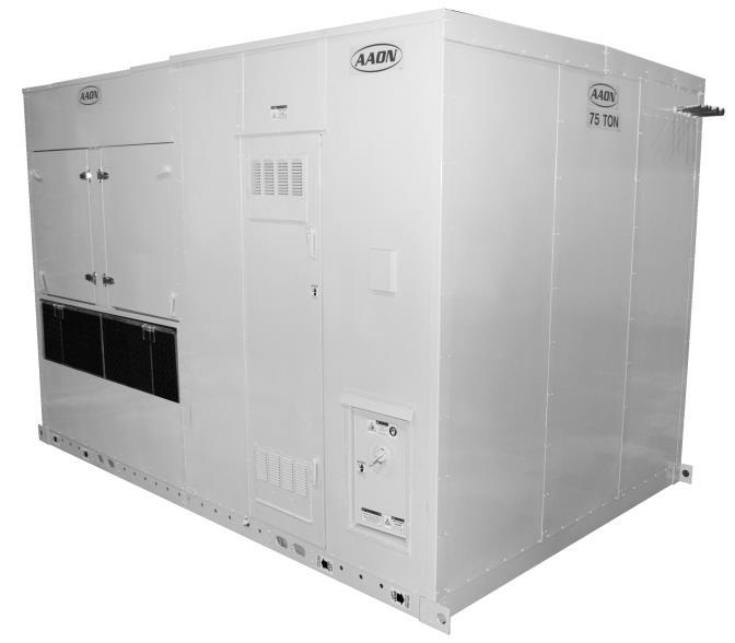

1 Condensing Units CL SERIES Installation, Operation & Maintenance
2 Table of Contents Safety... 7 CL Series Feature String Nomenclature GENERAL DESCRIPTION Unpacking: OWNER'S INFORMATION Warning: Wiring Diagrams: General Maintenance: INSTALLATION Lifting and Handling: Condenser Placement: Compressor Compartment Exhaust Fan: Mounting Isolation: Access Doors: Standard Evacuation Instructions: Low Ambient & Modulating Reheat System Evacuation Instructions: Charging Refrigerant: Before Charging: Checking Liquid Sub-cooling: Checking Evaporator Superheat: Special Low Ambient Charging Instructions: Low Ambient Operation: LAC Valve: Electrical: Refrigerant Piping Connections: Evaporative-Cooled Condenser Field Piping Connections: STARTUP Pre-Startup: Startup: Axial Flow Fans: Insert Blades: SERVICING AND MAINTENANCE General: Compressors: Refrigerant Suction Line Filter: Suction Filter Removal Instructions Refrigerant Liquid Line Filter Driers: Evaporator/Heat Exchangers: Lubrication: Service Information: Replacement Parts: AAON Technical Support Severe Service: Safety:
3 Performance: Warranties: Condenser Tube Inspection: Freeze Protection: Recirculating Water System: EVAPORATIVE-COOLED CONDENSER - PRE START-UP Cleanliness: Pump Operation: Running: Condenser Fan Motors: Water Make-up Valve: Water Treatment System: Sequence of Operation: EVAPORATIVE-COOLED CONDENSER - MAINTENANCE RECOMMEDATIONS Pump Maintenance: Fan Motor Maintenance: Access Doors: Bearings - Lubrication: Recommended Monthly Inspection: Mist Eliminators: Air Inlet: Stainless Steel Base Pan: Propeller Fans and Motors: Recommended Annual Inspection: Cleaning: EVAPORATIVE-COOLED CONDENSER - WATER QUALITY Recirculating Water Quality Guidelines: Mechanical Cleaning: Parts: AIR-COOLED CONDENSER E-Coated Coil Cleaning REFRIGERANT PIPING FOR THE CL SERIES General: Determining Refrigerant Line size: Equivalent Line Length: Liquid line sizing: Liquid Line Routing: Liquid Line Insulation: Liquid Line Guidelines: Liquid Line Accessories: Suction Line Sizing: Suction Line Routing: Suction Line Traps: Suction Line Insulation: Suction Line Guidelines: Suction Line Accessories: Hot Gas Bypass Line: Hot Gas Bypass Piping Considerations for Evaporator Above Condensing Unit:
4 4 Hot Gas Bypass Piping Considerations for Evaporator Below Condensing Unit: Hot Gas Bypass Line Guidelines: Hot Gas Reheat Line: Hot Gas Reheat Line Guidelines:... 44
5 Index of Tables and Figures Tables: Table 1 Service Clearances Table 2 - Acceptable Refrigerant Circuit Values Table 3 - Liquid Line Filter Drier Pressure Drop Table 4 - Water Quality Figures: Figure 1 CU evacuation connections Figure 2 CU evacuation connections Figure 3 AHU evacuation connections Figure 4 - Piping Schematic of Example system using the LAC valve Figure 5 - Refrigerant Piping Connections Figure 6 - Evaporative-Cooled Condenser Section Water Treatment Components Figure 7 - Water Level Sensor Figure 8 - Double Suction Riser Figure 9 - Oil Return Piping Figure 10 - Hot Gas Bypass Piping Diagram with air handler above condenser Figure 11 - Hot Gas Bypass Piping Diagram with air handler below condenser Figure 12 - Hot Gas Reheat Piping Diagram with air handler above condenser Figure 13 - Hot Gas Reheat Piping Diagram with air handler below condenser Figure 14 - Hot Gas Reheat Piping Diagram with air handler above condenser and field installed suction line accumulator Figure 15 - Hot Gas Reheat Piping Diagram with air handler above condenser and field installed suction line accumulator Figure 16 - Reheat/Hot Gas Bypass Piping Diagram with air handler above condenser Figure 17 - Reheat/Hot Gas Bypass Piping Diagram with air handler below condenser Figure 18 - Reheat/Hot Gas Bypass Piping Diagram with air handler evaporator above condenser and field installed suction line accumulator Figure 19 - Reheat/Hot Gas Bypass Piping Diagram with air handler below condenser and field installed suction line accumulator R10110 Rev. C
6 AAON CL Series Features and Options Introduction Energy Efficiency Air-Cooled or Energy Saving Evaporative- Cooled Condenser Direct Expansion Systems Tandem Scroll Compressors VFD Controlled Condenser Fans Humidity Control Modulating Hot Gas Reheat Safety Phase and Brownout Protection Automatic Low Pressure and Manual Reset High Pressure Safety Cut-outs Schrader Valves Internal Overload Protection on Tandem Scroll Compressors Aluminum Tread Plate Floor Covering Compressor Isolation Valves Installation and Maintenance Access Doors with Hinges, Lockable Handles and Rain Gutters Walk-In Weatherproof Compressor Compartment Run Test Report and Installation Manuals Included in Controls Compartment Color Coded Wiring and Wiring Diagrams Double Pane Viewing Windows Compressors are Deck Mounted with Rubber Isolation Three-Chemical Water Treatment System for Evaporative-Cooled Condenser Aluminum Tread Plate Floor Foam Insulated Double Wall Construction Replaceable Core Filter Driers System Integration Single Point Power Connection Air-Cooled or Evaporative Condensers Environmentally Friendly R-410A Refrigerant Extended Life 2,500 Hour Salt Spray Tested Exterior Corrosion Paint Optional 5 Year Non-Prorated Compressor Warranty Sloped Condenser Coils with Outer Protection 6
7 Safety Attention should be paid to the following statements: NOTE - Notes are intended to clarify the unit installation, operation and maintenance. CAUTION - Caution statements are given to prevent actions that may result in equipment damage, property damage, or personal injury. WARNING - Warning statements are given to prevent actions that could result in equipment damage, property damage, personal injury or death. DANGER - Danger statements are given to prevent actions that will result in equipment damage, property damage, severe personal injury or death. WARNING ELECTRIC SHOCK, FIRE OR EXPLOSION HAZARD Failure to follow safety warnings exactly could result in dangerous operation, serious injury, death or property damage. Improper servicing could result in dangerous operation, serious injury, death, or property damage. When servicing controls, label all wires prior to disconnecting. Reconnect wires correctly. Verify proper operation after servicing. Secure all doors with key-lock or nut and bolt. WARNING ELECTRIC SHOCK Electric shock hazard. Before servicing, shut off all electrical power to the unit, including remote disconnects, to avoid shock hazard or injury from rotating parts. Follow proper Lockout-Tagout procedures. WARNING QUALIFIED INSTALLER Improper installation, adjustment, alteration, service or maintenance can cause property damage, personal injury or loss of life. Startup and service must be performed by a Factory Trained Service Technician. A copy of this IOM should be kept with the unit. 7
8 WARNING FIRE, EXPLOSION OR CARBON MONOXIDE POISONING HAZARD Failure to replace proper controls could result in fire, explosion or carbon monoxide poisoning. Failure to follow safety warnings exactly could result in serious injury, death or property damage. Do not store or use gasoline or other flammable vapors and liquids in the vicinity of this appliance. WARNING GROUNDING REQUIRED All field installed wiring must be completed by qualified personnel. Field installed wiring must comply with NEC/CEC, local and state electrical code requirements. Failure to follow code requirements could result in serious injury or death. Provide proper unit ground in accordance with these code requirements. WARNING LIVE ELECTRICAL During installation, testing, servicing, and troubleshooting of the equipment it may be necessary to work with live electrical components. Only a qualified licensed electrician or individual properly trained in handling live electrical components shall perform these tasks. Standard NFPA-70E, an OSHA regulation requiring an Arc Flash Boundary to be field established and marked for identification of where appropriate Personal Protective Equipment (PPE) be worn, should be followed. WARNING ROTATING COMPONENTS Unit contains fans with moving parts that can cause serious injury. Do not remove grill containing fans until the power to the unit has been disconnected and fan has stopped rotating. WARNING VARIABLE FREQUENCY DRIVES Do not leave VFDs unattended in hand mode or manual bypass. Damage to personnel or equipment can occur if left unattended. When in hand mode or manual bypass mode VFDs will not respond to controls or alarms. 8
9 CAUTION VARIABLE FREQUENCY DRIVES Electric motor over-current protection and overload protection may be a function of the Variable Frequency Drive to which the motors are wired. Never defeat the VFD motor overload feature. The overload ampere setting must not exceed 115% of the electric motors FLA rating as shown on the motor nameplate. CAUTION DOOR LATCHES Door compartments containing hazardous voltage or rotating parts are equipped with door latches that allow locks. Door latches are shipped with a nut and bolt requiring tooled access. If the shipping hardware is not replaced with a pad lock, always re-install the nut and bolt after closing the door to maintain tooled access. CAUTION 3-PHASE ROTATION Rotation must be checked on all MOTORS AND COMPRESSORS of 3 phase units at startup by a qualified service technician. Scroll compressors are directional and can be damaged if rotated in the wrong direction. Compressor rotation must be checked using suction and discharge gauges. Fan motor rotation should be checked for proper operation. Alterations should only be made at the unit power connection WARNING UNIT HANDLING To prevent injury or death lifting equipment capacity shall exceed unit weight by an adequate safety factor. Always test-lift unit not more than 24 inches high to verify proper center of gravity lift point to avoid unit damage, injury or death. WARNING LEAK TESTING Do not use oxygen, acetylene or air in place of refrigerant and dry nitrogen for leak testing. A violent explosion may result causing injury or death. CAUTION PVC PIPING PVC (Polyvinyl Chloride) and CPVC (Chlorinated Polyvinyl Chloride) are vulnerable to attack by certain chemicals. Polyolester (POE) oils used with R-410A and other refrigerants, even in trace amounts, in a PVC or CPVC piping system will result in stress cracking of the piping and fittings and complete piping system failure. 9
10 CAUTION COMPRESSOR LUBRICANT Polyolester (POE) and Polyvinylether (PVE) oils are two types of lubricants used in hydrofluorocarbon (HFC) refrigeration systems. Refer to the compressor label for the proper compressor lubricant type. CAUTION COIL CLEANERS To prevent damage to the unit, do not use acidic chemical coil cleaners. Do not use alkaline chemical coil cleaners with a ph value greater than 8.5, after mixing, without first using an aluminum corrosion inhibitor in the cleaning solution. WARNING COIL CLEANERS Some chemical coil cleaning compounds are caustic or toxic. Use these substances only in accordance with the manufacturer s usage instructions. Failure to follow instructions may result in equipment damage, injury or death. CAUTION COIL CLEANING Do not clean DX refrigerant coils with hot water or steam. The use of hot water or steam on refrigerant coils will cause high pressure inside the coil tubing and damage to the coil. WARNING ENCLOSED AREA Do not work in an enclosed area where refrigerant or nitrogen gases may be leaking. A sufficient quantity of vapors may be present and cause injury or death. WARNING CONVENIENCE OUTLETS Factory installed convenience outlets are not intended for use while the unit is operating. 10
11 WARNING COMPRESSOR CYCLING 5 MINUTE MINIMUM OFF TIME To prevent motor overheating compressors must cycle off for a minimum of 5 minutes. 5 MINUTE MINIMUM ON TIME To maintain the proper oil level compressors must cycle on for a minimum of 5 minutes. The cycle rate must not exceed 6 starts per hour. 1. Startup and service must be performed by a Factory Trained Service Technician. 2. The unit is for outdoor use only. See General Information section for more information. 3. Every unit has a unique equipment nameplate with electrical, operational, and unit clearance specifications. Always refer to the unit nameplate for specific ratings unique to the model purchased. 4. READ THE ENTIRE INSTALLATION, OPERATION AND MAINTENANCE MANUAL. OTHER IMPORTANT SAFETY PRECAUTIONS ARE PROVIDED THROUGHOUT THIS MANUAL. 5. Keep this manual and all literature safeguarded near or on the unit. 11
12 CL Series Feature String Nomenclature Model Options Feature Options GEN SIZE VLT INT PRT A1 A2 A3 A4 B1 B2 B3 1A 1B 1C 1D A 5B 5C 6A 6B 6C A 14B CL B E : J A F 0 0 B H A 0 0 B 0 B CL Series Feature String Nomenclature MODEL OPTIONS Series and Generation CL Unit Size 045 = 45 Nominal Tons 060 = 60 Nominal Tons 070 = 70 Nominal Tons 075 = 75 Nominal Tons 095 = 95 Nominal Tons 100 = 100 Nominal Tons 110 = 110 Nominal Tons 125 = 125 Nominal Tons 134 = 134 Nominal Tons 135 = 135 Nominal Tons 155 = 155 Nominal Tons 170 = 170 Nominal Tons 190 = 190 Nominal Tons 210 = 210 Nominal Tons 230 = 230 Nominal Tons Voltage 2 = 230V/3Φ/60Hz 3 = 460V/3Φ/60Hz 4 = 575V/3Φ/60Hz 8 = 208V/3Φ/60Hz Interior Corrosion Protection 0 = Standard A1: Cooling - Compressor Style B = R-410A Dual Circuited Scroll Compressor R = R-410A Independently Circuited Compressors A2: Cooling - Condenser Style A = Air-Cooled Condenser E = Evaporative-Cooled Condenser A3: Cooling - Coating 0 = Standard B = Polymer E-Coated (Condenser) A4: Cooling - Staging 2 = 2 Stage 3 = 3 Stage 4 = 4 Stage 6 = 6 Stage 8 = 8 Stage B1: Heating - Type 0 = No Heat B2: Heating - Designation 0 = No Heat B3: Heating - Staging 0 = No Heat UNIT FEATURE OPTIONS 1A: Blank 0 = Standard 1B: Blank 0 = Standard 1C: Blank 0 = Standard 1D: Blank 0 = Standard 2: Blank 0 = Standard 3: Blank 0 = Standard 4: Blank 0 = Standard 12
13 CL Series Feature String Nomenclature Model Options Feature Options GEN SIZE VLT INT PRT A1 A2 A3 A4 B1 B2 B3 1A 1B 1C 1D A 5B 5C 6A 6B 6C A 14B CL B E : J AF 0 0 BH A 0 0 B 0 B A: Blank 0 = Standard 5B: Blank 0 = Standard 5C: Blank 0 = Standard 6A: Blank 0 = Standard 6B: Blank 0 = Standard 6C: Blank 0 = Standard 7: Refrigeration Control 0 = Standard A = 5 Min Time Delay Relay Off B = 20 Sec Time Delay Relay C = 115V Outlet, Field Wired D = 115V Outlet, Factory Wired E = Options A + B F = Options A + C G = Options A + D H = Options A + B + C J = Options A + B + D K = Options B + C L = Options B + D 8: Refrigeration Options 0 = Standard A = Hot Gas Bypass on Lead Stage D = Hot Gas Bypass on Lead and Lag Stages 9: Refrigeration Accessories 0 = Standard A = Sight Glass B = Compressor Isolation Valves C = Sight Glass + Compressor Isolation Valves F = Compressor Isolation Valves + Condenser Fan VFDs G = Compressor Isolation Valves + Condenser Fan VFDs + Sight Glass 10: Power Options 0 = Standard Single Point Power Block A = Single Point Power Non-Fused Disconnect (250A) B = Single Point Power Non-Fused Disconnect (400A) C = Single Point Power Non-Fused Disconnect (600A) D = Single Point Power Non-Fused Disconnect (800A) E = Single Point Power Non-Fused Disconnect (1200A) 11: Blank 0 = Standard 12: Controls 0 = Standard B = Phase & Brown Out Protection 13: Special Controls 0 = Standard D = VAV Unit Controller E = Constant Volume Unit Controller F = Make up Air Unit Controller H = Field Installed DDC Controls by Others J = Factory Installed DDC Controls by Others 13
14 CL Series Feature String Nomenclature Model Options Feature Options GEN SIZE VLT INT PRT A1 A2 A3 A4 B1 B2 B3 1A 1B 1C 1D A 5B 5C 6A 6B 6C A 14B CL B E : J A F 0 0 B H A0 0 B0 B A: Blank 0 = Standard 14B: Blank 0 = Standard 15: Blank 0 = Standard 16: Blank 0 = Standard 17: Blank 0 = Standard 18: Warranty 0 = Standard Warranty A = Extended Compressor Warranty Years : Code Options 0 = Standard ETL USA Listing A = M.E.A. (New York) D = Chicago - Cool Only H = ETL USA + Canada Listing 20: Blank 0 = Standard 21: Evaporative Condenser Option 0 = Standard, No Evaporative-Cooled Condenser A = Basic Package B = Low Ambient Package 22: Blank 0 = Standard 23: Paint and Special Pricing Authorization B = Standard Paint U = Special Price Authorization and Special Paint X = Special Price Authorization w/ Standard Paint 14
15 GENERAL DESCRIPTION All AAON CL Series condensers are factory assembled, wired, and shipped with a 100 psi nitrogen holding charge. Models are available for air-cooled and evaporative-cooled applications. Unpacking: When received, the unit should be checked for damage that might have occurred in transit. If damage is found it should be noted on the carrier s Freight Bill. A request for inspection by carrier s agent should be made in writing at once. Also, check the unit nameplate to ensure the correct model size and voltage have been received to match the job requirements. WARNING QUALIFIED INSTALLER Improper installation, adjustment, alteration, service or maintenance can cause property damage, personal injury or loss of life. Startup and service must be performed by a Factory Trained Service Technician. A copy of this IOM should be kept with the unit. OWNER'S INFORMATION Warning: Failure to observe the following instructions will result in premature failure of your system, and possible voiding of the warranty. Never cut off the main power supply to the unit, except for complete shutdown. When power is cut off from the unit, any compressors using crankcase heaters cannot prevent refrigerant migration. This means the compressor will cool down, and liquid refrigerant may accumulate in the compressor. Since the compressor is designed to pump refrigerant gas, damage may occur when power is restored. Before unit operation, the main power switch must be turned on for at least twenty four hours for units with compressor crankcase heaters. This will give the crankcase heater time to clear any liquid accumulation out of the compressor before it is required to run. Always control the system from the thermostat, or control panel, never at the main power supply (except for emergency or for complete shutdown of the system). Improper installation, adjustment, alteration, service, or maintenance can cause property damage, personal injury or loss of life. Installation and service must be performed by a qualified installer, service agency or if gas fired units, the gas supplier. Refer to installation instructions provided with the unit and this manual. The compressors must be on a minimum of 3 minutes and off for a minimum of 3 minutes. The cycle rate must be no more than 6 starts per hour. WARNING Scroll compressors will be damaged by operation with the wrong rotation. THE SUCTION PRESSURE TRANSDUCER HAS BEEN DISCONNECTED AFTER TESTING AT THE FACTORY. The wiring must be reconnected and proper rotation determined at the time of start-up by a qualified service technician using suction and discharge pressure gauges. Any alteration should be made at the unit power connection. The compressor life will be seriously shortened by reduced lubrication, and the pumping of excessive amounts of liquid oil and refrigerant. 15

16 Wiring Diagrams: A complete set of unit specific wiring diagrams in both ladder and point-to-point form are laminated in plastic and located inside the control compartment door. General Maintenance: When the initial startup is made and on a periodic schedule during operation, it is necessary to perform routine service checks on the performance of the condenser. This includes reading and recording suction pressures and checking for normal sub-cooling and superheat. See the evaporative-cooled condenser and aircooled condenser sections in this manual for specific details. INSTALLATION Lifting and Handling: If cables or chains are used to hoist the unit they must be the same length and care should be taken to prevent damage to the cabinet. Before lifting unit, be sure that all shipping material has been removed from unit. If the unit includes an evaporative-cooled condenser, make sure the tank is empty before lifting. Secure hooks and cables at all lifting points/lugs provided on the unit. Do not push, pull or lift the unit from anything other than its base. UNIT MUST BE RIGGED AT ALL MARKED LIFTING POINTS (Typical) Condenser Placement: The AAON condenser is designed for outdoor applications and mounting at ground level or on a rooftop. It must be placed on a level and solid foundation that has been prepared to support its weight. When installed at ground level, a onepiece concrete slab should be used with footings that extend below the frost line. With ground level installation, care must be taken to protect the coil fins from damage due to vandalism or other causes. The placement relative to the building air intakes and other structures must be carefully selected. Be sure to observe the dimensions that are on the rating plate of the condenser for operational and service clearances, which will appear as follows: Table 1 Service Clearances Location Unit Size Front - Vestibule Door Side 100" 142" Back - Opposite of Front 100" 142" Left Side - Condenser End 100" 100" Right Side - Opposite of Left 100" 100" Top UNOBSTRUCTED Condenser coils and fans must be free of any obstructions in order to start and operate properly with a correct amount of airflow. For proper unit operation, the immediate area around condenser must remain free of debris that may be drawn in and obstruct airflow in the condensing section. Consideration must be given to obstruction caused by snow accumulation when placing the unit. Compressor Compartment Exhaust Fan: Prior to unit operation the compressor compartment exhaust fan shipping support MUST BE removed from the exterior of the unit. The exhaust fan also requires the installation of the exterior rain hood provided with the unit. 16

17 Mounting Isolation: For roof mounted applications or anytime vibration transmission is a factor, vibration isolators may be used. Access Doors: A lockable access door is provided to the compressor and electrical compartment. A light switch is on the wall of the compressor control compartment. Standard Evacuation Instructions: Proper system evacuation is critical to remove moisture and non-condensables from the system before charging the system with refrigerant. Use the following procedure to ensure the entire system is pulled into a good vacuum. 1. System evacuation should be performed anytime a system is open to atmospheric pressure. The POE & PVE oils used with R-410A are extremely hydroscopic in nature and immediately begin pulling in moisture once the system is opened to the atmosphere. 2. Before starting to evacuate the system, you MUST ensure that there are no leaks by pressurizing the system with 400 psig of dry nitrogen and verifying no pressure loss after one hour. 3. Four valve manifold gauge sets are more effective than standard manifold gauge sets due to the extra hose port in combination with a 3/8 evacuation port. The larger diameter evacuation port will expedite system evacuation. 4. The manifold set should be connected to the condensing unit with one hose on the suction line service valve, one hose on the liquid line service valve and if an extra Schrader valve is field installed on the suction line, connect a third hose (not shown). The vacuum pump should be connected to the manifold set using a 3/8 vacuum rated hose. Figure 1 CU evacuation connections 5. An accurate micron gauge must be used and checked by pulling a vacuum on the gauge by itself and verify a rapid drop to less than 100 microns within a few minutes. 6. The micron gauge should not be attached to the system until the gauge manifold is reading 28 of vacuum to ensure the micron gauge does not see pressure and is thus damaged. MICRON GAUGES WILL BE DAMAGED BY PRESSURE!!! 7. It is a good practice to replace the vacuum pump oil after one hour of the evacuation process. The oil can be broken down in the pump in the initial first hour causing system evacuation to take longer than it should. 8. The minimum micron level required by AAON is 350 microns for systems using POE or PVE oils. 9. The system should then be isolated and the pump turned off to check for vacuum rise due to leaks or moisture in the system. The micron gauge should not rise above 500 microns after 30 minutes of wait time. 17

18 Low Ambient & Modulating Reheat System Evacuation Instructions: Proper system evacuation is critical to remove moisture and non-condensables from the system before charging the system with refrigerant. Systems with low ambient flooded condenser option require the following procedure to ensure the entire system is pulled into a good vacuum. 1. System evacuation should be performed anytime a system is open to atmospheric pressure. The POE & PVE oils used with R-410A are extremely hydroscopic in nature and immediately begin pulling in moisture once the system is opened to the atmosphere. 2. Open the reheat valve to 50% when evacuating. 3. Before starting to evacuate the system, you MUST ensure that there are no leaks by pressurizing the system with 400 psig of dry nitrogen and verifying no pressure loss after one hour. 4. Four valve manifold gauge sets are more effective than standard manifold gauge sets due to the extra hose port in combination with a 3/8 evacuation port. The larger diameter evacuation port will expedite system evacuation. 5. The manifold set should be connected to the condensing unit with one hose on the suction line service valve, one hose on the liquid line service valve, and a third hose on the reheat line service valve. The vacuum pump should be connected to the manifold set using a 3/8 vacuum rated hose. Figure 2 shows two circuits. The first circuit has a reheat line, the second circuit is just the suction and liquid line. Figure 2 CU evacuation connections 6. FAILURE to connect to the liquid line service valve will result in the receiver tank not being fully evacuated and most likely lead to non-condensables in the system. 7. An accurate micron gauge must be used and checked by pulling a vacuum on the gauge by itself and verify a rapid drop to less than 100 microns within a few minutes. 8. The micron gauge should not be attached to the system until the gauge manifold is reading 28 of vacuum to ensure the micron gauge does not see pressure and is thus damaged. MICRON GAUGES WILL BE DAMAGED BY PRESSURE!!! 18

19 9. The micron gauge should be attached to the system on the reheat line where it enters the air handler unit. See Figure 3 below. Reheat Line on the Outside of the Air Handler WARNING CLEAN AIR ACT The Clean Air Act of 1990 bans the intentional venting of refrigerant as of July 1, Approved methods of recovery, recycling, or reclaiming must be followed. Before Charging: Refer to the Unit Nameplate to determine the proper refrigerant to charge the system with. The unit being charged must be at or near full load conditions before adjusting the charge. Figure 3 AHU evacuation connections 10. It is a good practice to replace the vacuum pump oil after one hour of the evacuation process. The oil can be broken down in the pump in the initial first hour causing system evacuation to take longer than it should. 11. The minimum micron level required by AAON is 350 microns for systems using POE or PVE oils. 12. The system should then be isolated and the pump turned off to check for vacuum rise due to leaks or moisture in the system. The micron gauge should not rise above 500 microns after 30 minutes of wait time. Charging Refrigerant: Charging a system in the field must be based on determination of liquid sub-cooling and evaporator superheat. On a system with a thermostatic expansion valve liquid sub-cooling is more representative of the charge than evaporator superheat but both measurements must be taken. Units equipped with hot gas bypass must have the hot gas bypass valve closed to get the proper charge. Units equipped with hot gas reheat must be charged with the hot gas valve closed while the unit is in cooling mode. After adding or removing charge the system must be allowed to stabilize, typically minutes, before making any other adjustments. The type of unit and options determine the ranges for liquid sub-cooling and evaporator superheat. Refer to Table 2 when determining the proper sub-cooling. The vertical rise of the liquid line must be known in order to adjust the sub-cooling range for proper charge. Units equipped with low ambient (0 F) option see special charging instructions at the end of the charging instructions. 19
20 Checking Liquid Sub-cooling: 1. Measure the temperature of the liquid line as it leaves the condenser coil. 2. Read the gauge pressure reading of the liquid line close to the point where the temperature was taken. You must use liquid line pressure as it will vary from discharge pressure due to condenser coil pressure drop. 3. Convert the pressure obtained in Step 2 to a saturated temperature using the appropriate refrigerant temperature-pressure chart. 4. Subtract the measured liquid line temperature in Step 1 from the saturated temperature in Step 3 to determine the liquid sub-cooling. 5. Compare calculated sub-cooling to Table 2 for the appropriate unit type and options. Checking Evaporator Superheat: 1. Measure the temperature of the suction line close to the compressor. 2. Read gauge pressure at the suction line close to the compressor. 3. Convert the pressure obtained in Step 2 to a saturated temperature using the appropriate refrigerant temperature-pressure chart. 4. Subtract the saturated temperature in Step 3 from the measured suction line temperature in Step 1 to determine the evaporator superheat. 5. Compare calculated superheat to Table 2 for the appropriate unit type and options. Table 2 - Acceptable Refrigerant Circuit Values Air Cooled Condenser Evaporative Cooled Condenser Water Cooled Condenser Subcooling ( F) CAUTION Refrigerant overcharging leads to excess refrigerant in condenser coils resulting in elevated compressor discharge pressure. DO NOT OVERCHARGE! Superheat ( F) Sub-cooling W/Hot Gas Reheat ( F) 8-15* 8-15** 5-15* 6-10* 8-15** 8-12* 6-10* 8-15** 8-12* * Sub-cooling must be increased by 1 F per 10 feet of vertical liquid line rise for R-410A ** Superheat will increase with long suction line runs. The system is undercharged if: 1. The superheat is too high and 2. The sub-cooling is too low Correct an undercharged system by adding refrigerant to the system to reduce superheat and raise sub-cooling. If the sub-cooling is correct and the superheat is too high, the TXV may need adjustment to correct the superheat. Special Low Ambient Charging Instructions: For units equipped with low ambient refrigerant flood back option being charged in the summer when the ambient temperature is warm: If the ambient is above 70 F, charge to approximately 1-2 F of sub-cooling measured at the inlet to the expansion valve. Once enough charge has been added to get the evaporator superheat and sub-cooling values to the correct 20
21 setting more charge must be added. Add the calculated charge amount to flood the condenser coil. The additional charge is required for the system when running in cold ambient conditions. Contact Technical Support for this charge amount. AAON Technical Support Ph: (918) For units equipped with low ambient refrigerant flood back option being charged in the winter when the ambient temperature is cold: 1. If the ambient is below 70 F, charge to approximately 1-2 F of sub-cooling measured at the inlet to the expansion valve. Once enough charge has been added to get the evaporator superheat and sub-cooling values to the correct setting, more charge may need to be added. If the ambient temperature is 0 F, no more charge is required. If the ambient temperature is between 0 F and 70 F, multiply the charge amount needed at 70 F ambient (call AAON Technical Support to get this value) by the percentage below that corresponds to the ambient temperature. The result is the additional charge that must be added to the circuit. Condenser Ambient Temperature F 60 60% 50 37% 40 24% 30 15% 20 8% 0 0% % of flooded charge needed at 70 F ambient 2. The unit should be checked for proper operation once the ambient temperature is above 80 F. Low Ambient Operation: The AAON low ambient (condenser flood-back) system is used to operate a refrigerant system below 35 F outside air temperature. As the ambient temperature drops, the condenser becomes more effective therefore lowering the head pressure. When the head pressure gets too low, there will be insufficient pressure to operate the expansion valve properly. During low ambient temperatures, it is difficult to start a system because the refrigerant will migrate to the cold part of the system (condenser) and make it difficult for refrigerant to flow. The AAON low ambient system maintains normal head pressure during periods of low ambient by restricting liquid flow from the condenser to the receiver, and at the same time bypassing hot gas around the condenser to the inlet of the receiver. This backs liquid refrigerant up into the condenser reducing its capacity that in turn increases the condensing pressure. At the same time the bypassed hot gas raises liquid pressure in the receiver, allowing the system to operate properly. There are different types of low ambient control used. The following describe the different systems. Inspect the unit to determine the system used. 21
22 LAC Valve: The LAC valve is a non-adjustable three way valve that modulates to maintain receiver pressure. As the receiver pressure drops below the valve setting (180 psig for R-22 and 295 psig for R-410A), the valve modulates to bypass discharge gas around the condenser. The discharge gas warms the liquid in the receiver and raises the pressure to the valve setting. The following schematic shows an example system using the LAC valve. Figure 4 - Piping Schematic of Example system using the LAC valve 22
23 Electrical: The single point electrical power connections are made in the electrical control compartment. Check the unit data plate voltage to make sure it agrees with the power supply. Connect power to the unit according to the wiring diagram provided with the unit. The power and control wiring may be brought up through the utility entry. Protect the branch circuit in accordance with code requirements. Control wires and power should not be run inside the same conduit. The unit must be electrically grounded in accordance with the current National Electric Code. Power wiring is to the unit terminal block or main disconnect. All wiring beyond this point has been done by the manufacturer and cannot be modified without effecting the unit's agency/safety certification. WARNING ELECTRIC SHOCK Electric shock hazard. Before attempting to perform any installation, service, or maintenance, shut off all electrical power to the unit at the disconnect switches. Unit may have multiple power supplies. Failure to disconnect power could result in dangerous operation, serious injury, death, or property damage. Note: Startup technician must check motor amperage to ensure that the amperage listed on the motor nameplate is not exceeded. 23

24 Refrigerant Piping Connections: CL condensing unit refrigerant piping connections are located in the upper corner of the service vestibule side of the unit (opposite the condenser section) as shown in Figure 5. The piping connections are protected with a shipping cover that must be removed prior to copper connection and installation. Evaporative-Cooled Condenser Field Piping Connections: There are two field water connections that must be made for the evaporative-cooled condenser. There is a ¾ PVC socket city make-up water connection and a 2 PVC socket drain connection (as shown on the next page). This drain should connect to a sanitary sewer or other code permitted drain. These connections can go through the base or the wall of the unit. There is a cutout in the base with a cap that is 1 tall and the cap is sealed to the unit base to prevent any leaks in the unit from penetrating into the building. Any piping through the base should go through a field cutout in this cap. The pipes must be sealed to the cap once the piping is complete to prevent any leaks in the unit from penetrating into the building. A field cutout must be made in the wall if the evaporative-cooled condenser piping is to go through the unit wall. This cutout must be sealed once the piping is installed to prevent water from leaking into the unit. Figure 5 - Refrigerant Piping Connections 24

25 Figure 6 - Evaporative-Cooled Condenser Section Water Treatment Components 25
26 STARTUP Pre-Startup: After the installation and immediately before the startup of the condenser be sure that these items have been checked. 1. Verify that electrical power is available to the unit. 2. Verify that any remote stop/start device is requesting the condenser to start. While performing the Startup, use the Condensing Startup Form at the back of this booklet to record motor amps and any other comments. Startup: Use the General Check List at the top of the Startup Form to make a last check that all the components are in place and the power supply is energized. Note: Condensing fan operation should start with the first compressor. Cycle through all the compressors to confirm that all are operating within tolerance. When unit is running, observe the system for a complete operation cycle to verify that all systems are functioning properly. CAUTION Before leaving installation, a complete operating cycle should be observed to verify that all components are functioning properly. CAUTION COMPRESSOR ROTATION Scroll compressors are directional and will be damaged by operation in the wrong direction. Low pressure switches on compressors have been disconnected after factory testing. Rotation should be checked by a qualified service technician at startup using suction and discharge pressure gauges and any wiring alteration should only be made at the unit power connection. CAUTION 3-PHASE ROTATION Rotation must be checked on all MOTORS AND COMPRESSORS of three phase units. Condenser fan motors should all be checked by a qualified service technician at startup and any wiring alteration should only be made at the unit power connection. Variable frequency drives are programmed to automatically rotate the fan in the correct rotation. Do not rely on fans with variable frequency drives for compressor rotation. While performing the check, use the Condenser Startup Form to record observations of amps and refrigerant pressures. When all is running properly, place the controller in the Run mode and observe the system until it reaches a steady state of operation. 26
27 Axial Flow Fans: Multi-Wing Z Series Aluminum Fan Blade Pitch Angle Setting Instructions: Before You Begin, to maintain balance of fan: 1. Mark the hub castings across a joint, so the fan hub can be reassembled in the same orientation. 2. Mark the location of any balancing weight. Balancing weight will be on the outer bolt circle, in the form of washers, and/or longer bolts, or an additional balancing nut. Using diagrams in step 5, determine if the pin was in the hub (HUB) or retainer side (RET) of fan. Using table in step 4, find the possible blade pitch. Using table in step 3, select your blade angle based on whether your pin was in the HUB or RET. 3. Number the blades and blade sockets, so that they are replaced into their original position. 4. If possible, note the location of the pitch setting pin in the blade socket, and whether pin is located in the Hub or Retainer half of the fan. Step 1. Determine Boss Location Code: A or B The boss is the center section of the hub through which the fan is mounted to the shaft, and typically contains either setscrews or a center-tapered hole where the bushing inserts. Select boss location A or B: A is the boss on air inlet, including AS configurations. Step 3. Determine Hub/Retainer Code: HUB or RET Step 4. - Determine Groove Number: 1 or 2 or 3 or 4 B is the boss on air discharge, including BS. For flange mounted fans, use boss location A for R rotation fans, and boss location B for L rotation fans. Step 2. Find Blade Pitch Angle: ( 20, 25, 27.5, 30, 32.5, 35, 37.5, 40, 45 or 50 ) Carefully disassemble fan on flat surface and note in which groove the pin is located. Refer to groove number code diagram. 27

28 Step 5. Final Assembly Definition of HUB and RET for purposes of instructions. For 2-piece hubset: To finish, tighten the bolts in a cross pattern to 5 to 6 ft-lbs of torque. Multi-Wing W Series Black Glass Reinforced Polypropylene Fan Blade Pitch Angle Setting Instructions: Step 1. Note original position of retaining plates, center boss and all hardware including additional hardware used for balancing. Step 2. Remove all the bolts and nuts. Step 3. Determine blade rotation on the concave side of the blade is a blade marking showing 6WR, 6WL, 7WL, 7WR, or 9WR. The L and R denote the rotation of the blade. Using the HUB or RET code found in Step 3: Step 4. Replace the pitch insert in the blade root with an insert of the desired pitch. If code is HUB, place the hub down on work surface first (one or two pieces, depending on above). If code is RET, place one retainer ring only down on the work surface first. (A weighted coffee can could be used to elevate the fan from the work surface). Using the groove number, place the locking pin in the groove number that was found in Step 4. Insert Blades: Place the blade over the pin in the hub/retainer blade socket, so that the pin also fits into the appropriate pitch angle groove in the blade. Repeat for all blades. Assemble hub set together, aligning the match marks that were made. Replace any balancing weight to its original position. Step 5. Replace blades to their original location. Step 6. Replace all nuts, bolts, and washers on the fan hub. Step 7. Replace retaining plates and center boss to original location. Step 8. Tighten nuts and bolts to 14 ft-lbs of torque. 28
.")


29 SERVICING AND MAINTENANCE General: Qualified technicians must perform routine service checks and maintenance. This includes reading and recording the condensing and suction pressures and checking for normal subcooling and superheat (see Charging Refrigerant:). Air-cooled and evaporative-cooled condenser units require different maintenance schedules/procedures. Unit specific instructions for both types are included in this manual. Compressors: The scroll compressors are fully hermetic and require no maintenance except keeping the shell clean. Suction Filter Removal Instructions 1. Shut down operation of the unit 2. Close both shut-off valves to isolate the suction filter 3. Reclaim the refrigerant from the suction filter section 4. Remove the bolts from the suction filter end plate Refrigerant Suction Line Filter: Each refrigerant circuit contains a replaceable core suction line filter. One month after startup, remove the filter element. The replaceable core suction filters are provided with pressure taps and shutoff valves for isolation when removing the filter. For safety purposes a service manifold must be attached prior to filter maintenance. 5. Remove the pleated filter assembly WARNING Prior to filter core service, a service manifold MUST BE attached to in and out pressure connections to assure no pressure exists during filter maintenance. Non-compliance could result in injury or violation of EPA regulations. WARNING 6. Replace the suction filter end plate and bolts 7. Evacuate the suction filter assembly to 500 microns 8. Open both shut-off valves Service gauges MUST BE connected before operating the isolation valves for the replaceable core filter. 29
30 Refrigerant Liquid Line Filter Driers: Each refrigerant circuit contains a replaceable core filter drier. Replacement is recommended when there is excessive pressure drop across the assembly or moisture is indicated in a liquid line sight glass. Table 3 - Liquid Line Filter Drier Pressure Drop The filter driers are provided with pressure taps and shutoff valves for isolation when changing the core. For safety purposes a service manifold must be attached prior to filter maintenance. WARNING Prior to filter core service, a service manifold MUST BE attached to in and out pressure connections to assure no pressure exists during filter maintenance. Non-compliance could result in injury or violation of EPA regulations. WARNING Service gauges MUST BE connected before operating the isolation valves for the replaceable core filter. Evaporator/Heat Exchangers: Normally no maintenance or service work will be required for a matching direct expansion evaporator with a thermal expansion valve to regulate refrigerant. Lubrication: All original motors and bearings are furnished with an original factory charge of lubrication. Certain applications require bearings be relubricated periodically. The schedule will vary depending on operating duty, temperature changes, or severe atmospheric conditions. Bearings should be re-lubricated at normal operating temperatures, but not when running. Rotate the fan shaft by hand and add only enough grease to purge the seals. DO NOT OVERLUBRICATE. Service Information: If the unit will not operate correctly and a service company is required, only a company with service technicians qualified and experienced in both condensing units and air conditioning are permitted to service the systems to keep warranties in effect. If assistance is required, the service technician must contact AAON. Replacement Parts: Parts for AAON equipment may be obtained from your local AAON representative. When ordering parts reference the unit serial number and part number. AAON Technical Support 2424 S. Yukon Ave. Tulsa, OK Ph: (918) techsupport@aaon.com Note: Before calling, technician should have model and serial number of the unit available for the service department to help answer questions regarding the unit 30


31 EVAPORATIVE-COOLED CONDENSER - GENERAL Evaporative cooling equipment rejects heat by evaporating a portion of the recirculated water spray and discharging it from the unit with the hot, saturated air. As the spray water evaporates, it leaves behind the mineral content and impurities of the supply water. If these residuals are not purged from the water distribution system, they will become concentrated and lead to scaling, corrosion, sludge build-up and biological fouling. A water treatment monitoring and control system has been furnished with this unit. Be sure to read the complete manual that has been furnished. All water treatment is a combination of bleed water and chemical treatment for proper control of the residuals and to prevent any biological contamination. WARNING Batch-loading chemicals into the unit IS NOT PERMITTED. The control system must regulate the chemical feed. Severe Service: The following recommended maintenance procedures are basic requirements for normal operating environments. For severe operating conditions, the frequency of inspection and service should be increased. Air containing industrial and chemical fumes, salt, dust, or other airborne contaminates and particulates will be absorbed by the recirculating water system and may form solutions and deposits harmful to the products and personnel. Safety: The recirculating water system contains chemical additives for water quality control and biological contaminants removed from the air by the washing action of the water. Personnel exposed to the saturated effluent, drift, or direct contact should use proper precaution. Proper location of the evaporative-cooled condenser requires good judgment to prevent the air discharge from entering fresh air intakes or to avoid allowing contaminated building exhaust from entering the condenser. Follow local and national codes in locating the evaporative-cooled condenser but as minimum the evaporative-cooled condenser sump must be 15 feet from the nearest intake. WARNING The evaporative condenser must be thoroughly cleaned on a regular basis to minimize the growth of bacteria, including Legionella Pneumophila, to avoid the risk of sickness or death. Service personnel must wear proper personal protective equipment. DO NOT ATTEMPT ANY SERVICE UNLESS THE FAN MOTOR IS LOCKED OUT. 31
32 Performance: Improper location of the evaporative-cooled condenser may seriously degrade the capacity of the equipment. Make sure the equipment is located such that discharge air from the condenser does not enter the condenser air inlet. Warranties: Please refer to the limitation of warranties in effect at the time of purchase. Condenser Tube Inspection: The coil is leak tested at 450 psig before shipment. AAON will not be responsible for loss of refrigerant. It is the responsibility of the installer to verify that the system is sealed before charging with refrigerant. If the unit is operated during low ambient temperature conditions, freeze protection for the recirculating water system must be provided. Freeze Protection: In order to prevent water temperatures from dropping below 50 F, this unit is equipped with a variable frequency drive (VFD) on the fan motors when the refrigeration system is operating. Recirculating Water System: Electric sump heaters are available to keep the sump water from freezing when the refrigeration system is not operating. An electric resistance heater is supplied in the vestibule when sump heaters are selected. Note: The condenser should not be operated with the fan on and the pump cycled on and off to maintain head pressure control under any conditions. The unit is equipped with a water temperature controller which varies fan speed to maintain sump water temperature. This unit is not equipped with a compressor discharge pressure controller for fan speed modulation and therefore can not be operated without water flow. EVAPORATIVE-COOLED CONDENSER - PRE START-UP Do not start the evaporative-cooled condenser or compressors without installation of proper water treatment chemicals. Contact your local water treatment expert for correct selection of water treatment chemical, adjustment of chemical feed and bleed rates. Reverse osmosis and deionized water is corrosive and cannot be used on the CL evaporative cooled condensing units. Cleanliness: Dirt and debris may accumulate in the sump during shipping and storage. The sump should be cleaned prior to start-up to prevent clogging the water distribution system. Any surfaces that show contamination should be cleaned ONLY with a commercial stainless steel cleaner to restore the initial appearance. The inlet screens should be inspected for foreign material. Pump Operation: Before initial start of the pump, check as follows: 1. Be sure that pump operates in the direction indicated by the arrow on the pump casing. Check rotation each time motor leads have been disconnected. 2. Check all connections of motor and starting device with wiring diagram. Check voltage, phase and frequency of line circuit with motor name plate. 3. Check suction and discharge piping and pressure gauges for proper operation. 4. Turn rotating element by hand to assure that it rotates freely. Running: Periodically inspect pump while running, but especially after initial start-up and after repairs. 1. Check pump and piping for leaks. Repair immediately. 32
33 2. Record pressure gauge readings for future reference. 3. Record voltage, amperage per phase, and kw. Condenser Fan Motors: The direct-drive condenser motors on AAON evaporative-cooled condensers are 1200-rpm premium efficiency motors controlled by a VFD. These motors are totally enclosed air over motors with weep holes in the bottom end bell so that any condensation can drain out of the motor. The motors have a small electric resistance heater installed inside the casing to keep the motors warm when they are deactivated. The heaters are designed to keep the interior of the motor 10 F warmer than the surrounding ambient temperature. This prevents condensation from forming inside the motor. If the water in the sump is below the low probe, it will not allow the condenser pump or the sump heater to operate. It will activate the make-up water solenoid to try to fill the sump assuming water is flowing to the unit. Once water is above the low probe, it will allow the condenser pump and sump heater (if ordered and the ambient temperature is below 40 F) to operate. The make-up water solenoid will remain activated until water gets to the high water level. The make-up water solenoid will deactivate until water gets to the medium water level. In normal operation, the water level should swing between the medium and high water levels. The maximum high water level should be 1 below the overflow drain which occurs after the makeup water valve shuts off when the water level reaches the high level probe. Ensure that fan is tightly mounted to the motor shaft and the motor mounting bolts are aligned and secure. Water Make-up Valve: The sump water level is controlled by a set of conductivity probes at different levels in the sump. This water level controller is located in the vestibule behind the condenser pump. There are four conductivity probes in this controller. There is a reference probe (shown as ref on the wiring diagram). This probe is one of the two longest probes. The other long probe is the low water level probe (shown as lo on the wiring diagram). The medium length probe is for the medium water level (shown as med on the wiring diagram). The short probe is for the high water level (shown as hi on the wiring diagram). There is a solenoid valve in the makeup water line that is activated by the water level controller. The water level controller determines the level of water in the sump based on conductivity between two probes. If the controller sees conductivity between two probes, it knows that water is at least at the level of that probe. Figure 7 - Water Level Sensor Make-up water supply pressure should be maintained between 15 and 60 psig for proper operation of the valve. The make-up water valve assembly should be inspected monthly and adjusted as required. Replace the valve seat if leakage occurs when the valve is in the closed position. 33
34 Water Treatment System: All AAON evaporative-cooled condensers come equipped with a water treatment system that should be maintained by a local water treatment professional trained in the water treatment of evaporative condensers. This system consists of a controller, three chemical pumps and storage tanks, a conductivity sensor, a motorized ball valve for water bleed, and a water meter. One chemical pump and tank is typically used for a descaling chemical to prevent scale from forming in the condenser. The other two pumps and tanks are typically used for two different biocides (to kill any microorganisms that could grow in the condenser). Two biocides are used to prevent organisms from becoming resistant to one chemical. The mineral content of the water must be controlled. All make-up water has minerals in it. As water is evaporated from the condenser, these minerals remain. As the mineral content of the water increases, the conductivity of the water increases. The water treatment controller monitors this conductivity. As the water conductivity rises above set point, the controller will open a motorized ball valve on the discharge side of the condenser pump and dumps water into the condenser drain until conductivity is lowered. While the motorized ball valve is opened, the controller will not disperse chemicals. The chemicals are dispersed by the water treatment controller based on the scheduled input by the water treatment professional. (See the separate manual for the water treatment controls for specific programming information.) The water meter measures the quantity of makeup water used by the condenser. Any water treatment program must be compatible with stainless steel, copper, aluminum, ABS plastic and PVC. Batch feed processes should never be used as concentrated chemicals can cause corrosion. Never use hydrochloric acid (muriatic acid) as it will corrode stainless steel. Sequence of Operation: On a call for cooling, the condenser pump is activated. A pressure switch in the pump discharge is bypassed for six seconds by a time delay relay in order for the pump to establish recirculating water flow. If flow is not proven within the six seconds, the pressure switch opens, breaking the safety circuit, thereby shutting down the entire system. This pressure switch is set to close at 3 psi and open at 1 psi. A Johnson Controls S350C measures the water temperature in the pump discharge line. If the sump water temperature exceeds 105 F, the cooling system will be shut down thereby preventing damage to the evaporative condenser. If a fault occurs in the evaporative condenser fan motor VFD, normally closed fault terminals on the VFD will interrupt the safety circuit, thereby shutting down the system. If the VFD does fault and cannot be reset, there is a VFD bypass switch mounted near the VFD. This switch has four positions line, off, drive, and test. The line position will bypass the VFD, sending power to the motor. In this position, the condenser fans will run at full speed. The off position will not allow power to pass through the switch. This functions as a disconnect switch. The drive position runs power through the VFD. This is the normal operation for the switch. The test position routes power to the VFD but not to the motor. This is useful for running tests on the VFD without sending power to the motor. A Johnson Controls A350P controls the VFD speed. This device sends a 0-10 VDC signal to the VFD. This controller is set to maintain a sump temperature of 70 F. On a rise in sump temperature, the controller increases the voltage to the VFD, increasing the speed of the condenser fans. Conversely, on a drop in sump temperature, the controller will decrease the voltage to the VFD, decreasing the speed of the condenser fans. 34
35 An outside air thermostat does not allow the condenser to operate when the ambient temperature is below 35 F. EVAPORATIVE-COOLED CONDENSER - MAINTENANCE RECOMMEDATIONS Pump Maintenance: Cleaning - Remove oil, dust, water, and chemicals from exterior of motor and pump. Keep motor air inlet and outlet open. Blow out interior of open motors with clean compressed air at low pressure. Labeled Motors - It is imperative for repair of a motor with Underwriters Laboratories label that original clearances be held; that all plugs, screws, other hardware be fastened securely, and that parts replacements be exact duplicates or approved equals. Violation of any of the above invalidates Underwriters Label. Fan Motor Maintenance: Same as pump maintenance Access Doors: If scale deposits or water is found around the access doors, adjust door for tightness. Adjust as necessary until leaking stops when door is closed. Bearings - Lubrication: Every 6 months or after a prolonged shut down. Use waterproof, lithium based grease. Below 32 F - Esso Exxon or Beacon 325. Above 32 F Mobil Mobilox EP2, Shell Alvania EP2 or Texaco RB2. Recommended Monthly Inspection: 1. Clean sump section interior. Dirt and other impurities which have accumulated in the sump should be removed from the sump area. Shut off make-up water ball valve and open the drain connection for flushing of the sump. 2. Clean dirt out of sump using a water hose (not a pressure washer). 3. Clean sump suction strainer. 4. Check water operating level. Adjust float as required. 5. Inspect fan motor(s) and water circulation pump(s) and lubricate per the lubrication nameplate or manufacture s recommendations. 6. Inspect axial fans and eliminators removing any debris which may have accumulated during operation. 7. Inspect the water distribution system to insure that nozzles and spray orifices are functioning correctly. The inspection should be made with the circulation pump on and fans off. Mist Eliminators: The mist eliminators must be correctly positioned when they are replaced during cleaning or service. Air Inlet: Inspect the air inlet louvers and mist eliminators into the condenser section on a monthly basis to remove any paper, leaves or other debris that may block the airflow. Stainless Steel Base Pan: The base pan under the tube bundles is stainless steel and may sometimes become tarnished due to contamination. These surfaces should be inspected yearly to ensure they remain clean of any contamination that may result in damage. Any surfaces that show contamination should be cleaned ONLY with a commercial stainless steel cleaner to restore the initial appearance. Propeller Fans and Motors: The fans are directly mounted on the motor shafts and the assemblies require minimal maintenance except to assurance they are clear of dirt or debris that would impede the airflow. 35

36 Recommended Annual Inspection: In addition to the above maintenance activities, a general inspection of the unit surface should be completed at least once a year. Remove spray header and flush out. Cleaning: Mechanical cleaning, including pressure washing, should never be performed as surfaces and seals could be damaged. Chemical cleaning that is safe for stainless steel, copper, aluminum, ABS plastic and PVC is the only acceptable means of cleaning the evaporative condenser. A proper water treatment program should reduce cleaning needs. EVAPORATIVE-COOLED CONDENSER - WATER QUALITY Recirculating Water Quality Guidelines: Table 4 - Water Quality Cycles of concentration (the ratio of dissolved solids in recirculated water to dissolved solids in make-up), should be determined and monitored frequently by a competent water treatment expert. To limit cycles of concentration to maintain the above guideline, it is necessary to bleed a certain portion of the recirculated water. This is achieved automatically with a solenoid valve actuated by a conductivity meter set at the desired conductivity corresponding to the desired cycles of concentration. It should be noted that these are guidelines and even though these individual values are met, under certain conditions the water quality can be aggressive. For example, water with very low alkalinity and levels of chlorides and sulfates approaching maximum recommended levels can be corrosive. Mechanical Cleaning: Do not attempt to mechanically clean the copper tubing in the evaporative-cooled condenser. Do not use wire brushes or any other mechanical device on the copper tubing. Severe damage may result. Contact your water treatment expert for recommendations on chemical cleaning procedures. Parts: Contact your local AAON Representative for factory authorized parts. Orders must include the Serial Number from the product nameplate OR visit for more information. AIR-COOLED CONDENSER The air-cooled condenser section rejects heat by passing outdoor air over the fin tube coils for cooling of the hot refrigerant gas from the compressors. The heated air will discharge from the top of the section through the axial flow fans. The condenser coils should be inspected yearly to ensure unrestricted airflow. If the installation has a large amount of airborne dust or other material, the condenser coils should be cleaned with a water spray in a direction opposite to airflow. Care must be taken to prevent bending of the aluminum fins on the copper tube. E-Coated Coil Cleaning Documented quarterly cleaning of e-coated coils is required to maintain coating warranty coverage. WARNING Electric shock hazard. Shut off all electrical power to the unit to avoid shock hazard or injury from rotating parts. Surface loaded fibers or dirt should be removed prior to water rinse to prevent restriction of airflow. If unable to back wash the side of the coil opposite of the coils entering air side, then 36
CL SERIES Installation, Operation & Maintenance
 Condensing Units CL SERIES Installation, Operation & Maintenance Table of Contents GENERAL DESCRIPTION... 8 Unpacking:... 8 OWNER'S INFORMATION... 8 Warning:... 8 Wiring Diagrams:... 9 General Maintenance:...
CF Series. Installation, Operation, & Maintenance. Condenser and Condensing Units WARNING
 CF Series Condenser and Condensing Units Installation, Operation, & Maintenance WARNING If the information in this manual is not followed exactly, a fire or explosion may result causing property damage,
CN Series. Installation, Operation, & Maintenance. Condensing Units WARNING WARNING WARNING QUALIFIED INSTALLER
 CN Series Condensing Units Installation, Operation, & Maintenance WARNING QUALIFIED INSTALLER Improper installation, adjustment, alteration, service or maintenance can cause property damage, personal injury
LN Series. Installation, Operation, & Maintenance. Chillers and Outdoor Mechanical Rooms
 LN Series Chillers and Outdoor Mechanical Rooms Installation, Operation, & Maintenance WARNING FIRE OR EXPLOSION HAZARD Failure to follow safety warnings exactly could result in serious injury, death or
CB SERIES. Installation, Operation & Maintenance. Condensing Units WARNING WARNING WARNING FOR YOUR SAFETY QUALIFIED INSTALLER
 CB SERIES Condensing Units Installation, Operation & Maintenance WARNING QUALIFIED INSTALLER Improper installation, adjustment, alteration, service or maintenance can cause property damage, personal injury
LL Series. Installation, Operation & Maintenance. Chillers and Outdoor Mechanical Rooms
 LL Series Chillers and Outdoor Mechanical Rooms Installation, Operation & Maintenance WARNING FIRE OR EXPLOSION HAZARD Failure to follow safety warnings exactly could result in serious injury, death or
LF Series. Installation, Operation, & Maintenance. Air-Cooled Chillers WARNING WARNING WARNING
 LF Series Air-Cooled Chillers Installation, Operation, & Maintenance WARNING If the information in this manual is not followed exactly, a fire or explosion may result causing property damage, personal
LF Series. Installation, Operation, & Maintenance. Air-Cooled Condenser Chillers WARNING WARNING WARNING
 LF Series Air-Cooled Condenser Chillers Installation, Operation, & Maintenance WARNING If the information in this manual is not followed exactly, a fire or explosion may result causing property damage,
LZ Series. Installation, Operation, & Maintenance. Chillers and Outdoor Mechanical Rooms
 LZ Series Chillers and Outdoor Mechanical Rooms Installation, Operation, & Maintenance WARNING FIRE OR EXPLOSION HAZARD Failure to follow safety warnings exactly could result in serious injury, death or
LC Series. Installation, Operation & Maintenance. Air-Cooled Condenser Chillers WARNING WARNING WARNING
 LC Series Air-Cooled Condenser Chillers Installation, Operation & Maintenance WARNING If the information in this manual is not followed exactly, a fire or explosion may result causing property damage,
F1 Series. Installation, Operation & Maintenance. Indoor Air Handing Units WARNING WARNING WARNING NOTICE QUALIFIED INSTALLER
 F1 Series Indoor Air Handing Units Installation, Operation & Maintenance WARNING QUALIFIED INSTALLER Improper installation, adjustment, alteration, service or maintenance can cause property damage, personal
WMHP Series R410a Heat Pump INSTALLATION INSTRUCTIONS
 WMHP Series R410a Heat Pump INSTALLATION INSTRUCTIONS **WARNING TO INSTALLER, SERVICE PERSONNEL AND OWNER** Altering the product or replacing parts with non authorized factory parts voids all warranty
H3/V3 Series. Installation, Operation & Maintenance. Horizontal and Vertical Indoor Air Handling Units WARNING WARNING WARNING
 H3/V3 Series Horizontal and Vertical Indoor Air Handling Units Installation, Operation & Maintenance WARNING WARNING QUALIFIED INSTALLER Improper installation, adjustment, alteration, service or maintenance
SA SERIES. Installation, Operation & Maintenance. Vertical Self-Contained Units and Indoor Air Handling Units WARNING WARNING WARNING
 Vertical Self-Contained Units and Indoor Air Handling Units SA SERIES Installation, Operation & Maintenance QUALIFIED INSTALLER Improper installation, adjustment, alteration, service or maintenance can
Service Step by Step Trouble-Shooting Check-List
 WARNING: Only Data Aire trained technician or experience technicians should be working on Data Aire Equipment. Protect yourself at all times and work safe. Date: Dates at the job site: From: to Job#: Serial#:
PARALLEL RACK SYSTEM INSTALLATION & OPERATIONS MANUAL With Master Rack Compressor Sequencer
 PARALLEL RACK SYSTEM INSTALLATION & OPERATIONS MANUAL With Master Rack Compressor Sequencer 5/16 Rev. A 57-02509 2 Contents INTRODUCTION... 4 WARNING LABELS AND SAFETY INSTRUCTIONS... 5 PS SERIES PARALLEL
V3 Series. Installation, Operation & Maintenance. Vertical Indoor Air Handling Units WARNING WARNING WARNING QUALIFIED INSTALLER
 V3 Series Vertical Indoor Air Handling Units Installation, Operation & Maintenance QUALIFIED INSTALLER Improper installation, adjustment, alteration, service or maintenance can cause property damage, personal
Condensing Unit Installation and Operating Instructions
 Bulletin WCU_O&I 01 June 2003 Condensing Unit Installation and Operating Instructions WCU Air Cooled Condensing Unit Table of Contents Section 1. Section 2. Section 3. Section 4. Section 5. Section 6.
Installation, Operation & Maintenance
 Installation, Operation & Maintenance Packaged Rooftop Units, Heat Pumps, & Outdoor Air Handling Units FIRE OR EXPLOSION HAZARD Failure to follow safety warnings exactly could result in serious injury,
H3 Series. Installation, Operation & Maintenance. Horizontal Indoor Air Handling Units WARNING WARNING WARNING QUALIFIED INSTALLER
 H3 Series Horizontal Indoor Air Handling Units Installation, Operation & Maintenance QUALIFIED INSTALLER Improper installation, adjustment, alteration, service or maintenance can cause property damage,
TECHNICAL GUIDE DESCRIPTION SPLIT-SYSTEM AIR-COOLED CONDENSING UNITS MODELS: HF-07 FEATURES B-0703
 TECHNICAL GUIDE SPLIT-SYSTEM AIR-COOLED CONDENSING UNITS MODELS: HF-07 DESCRIPTION These Sunline 2000 units are completely assembled, piped and wired at the factory to provide one-piece shipment and rigging.
KITS COMMON TO HEATING AND COOLING EQUIPMENT 504,652M 03/04. Supersedes 503,249M
 2004 Lennox Industries Inc. Dallas, Texas KITS COMMON TO HEATING AND COOLING EQUIPMENT 504,652M 03/04 Supersedes 503,249M Litho U.S.A. COMPRESSOR REPLACEMENT KIT INSTALLATION INSTRUCTIONS FOR COMPRESSOR
Installation, Operation, and Maintenance Information
 Installation, Operation, and Maintenance Information Low Velocity Unit Coolers Bulletin No. IOM 110.3 Table of Contents Inspection... 2 Installation... 2 4 General... 2 Location... 2 Drain Line... 3 Refrigerant
RN SERIES. Installation, Operation, & Maintenance. Packaged Rooftop Units, Heat Pumps, & Outdoor Air Handling Units WARNING WARNING
 RN SERIES Packaged Rooftop Units, Heat Pumps, & Outdoor Air Handling Units Installation, Operation, & Maintenance WARNING FIRE OR EXPLOSION HAZARD Failure to follow safety warnings exactly could result
SB Series. Installation, Operation & Maintenance. Vertical Self-Contained Units WARNING WARNING
 SB Series Vertical Self-Contained Units Installation, Operation & Maintenance QUALIFIED INSTALLER Improper installation, adjustment, alteration, service or maintenance can cause property damage, personal
Standard and CELDEK Evaporative Cooler Modules Installation, Operation, and Maintenance Manual
 Standard and CELDEK Evaporative Cooler Modules Installation, Operation, and Maintenance Manual Standard Evaporative Cooler CELDEK Evaporative Cooler RECEIVING AND INSPECTION Upon receiving unit, check
Liebert Small System MCD and PFH Condensers (1-5 Ton) Warranty Inspection Check Sheet
 Warranty Inspection Check Sheet") The following information must be fully completed and forwarded to your local Liebert sales office to establish your equipment warranty. Installer Address Owner Address Owner e-mail address Installation
The following information must be fully completed and forwarded to your local Liebert sales office to establish your equipment warranty. Installer Address Owner Address Owner e-mail address Installation
RN SERIES. Installation, Operation & Maintenance. Packaged Rooftop Units, Heat Pumps, & Outdoor Air Handling Units WARNING WARNING
 RN SERIES Packaged Rooftop Units, Heat Pumps, & Outdoor Air Handling Units Installation, Operation & Maintenance WARNING FIRE OR EXPLOSION HAZARD Failure to follow safety warnings exactly could result
TECHNICAL GUIDE. Description SPLIT-SYSTEM AIR-COOLED CONDENSING UNITS YD360, 480 & THRU 50 NOMINAL TONS YTG-B-0811
 Description These units are completely assembled, piped and wired at the factory to provide one-piece shipment and rigging. Each unit is pressurized with a holding charge of Refrigerant R-410A for storage
INSTALLATION INSTRUCTIONS TXV Horizontal Slab Coils WLSH
 TXV Horizontal Slab Coils WLSH These instructions must be read and understood completely before attempting installation. It is important that the Blower and Duct System be properly sized to allow the system
CELDEK Evaporative Cooler Module Installation, Operation, and Maintenance Manual. CELDEK Evaporative Cooler
 CELDEK Evaporative Cooler Module Installation, Operation, and Maintenance Manual CELDEK Evaporative Cooler RECEIVING AND INSPECTION Upon receiving unit, check for any interior and exterior damage, and
Some of these procedures need to be performed to conform to requirements of the Clean Air Act.
 Leak Detection, Recovery, Evacuation and Charging Four basic service procedures used to repair and maintain a mechanical refrigeration system are leak detection, evacuation, recovery, and refrigerant charging.
INSTALLATION INSTRUCTIONS TXV Horizontal Duct Coils EHD
 TXV Horizontal Duct s EHD These instructions must be read and understood completely before attempting installation. It is important that the Blower and Duct System be properly sized to allow the system
Standard and CELDEK Evaporative Cooler Modules Installation, Operation, and Maintenance Manual
 Standard and CELDEK Evaporative Cooler Modules Installation, Operation, and Maintenance Manual Standard Evaporative Cooler CELDEK Evaporative Cooler RECEIVING AND INSPECTION Upon receiving unit, check
Calhoon MEBA Engineering School. Study Guide for Proficiency Testing Refrigeration
 Calhoon MEBA Engineering School Study Guide for Proficiency Testing Refrigeration 1. To prevent an injury when working with refrigerants, what safety precautions are necessary? 2. When halogens are in
B. Unit construction shall comply with ASHRAE 15 Safety Code, NEC, and ASME applicable codes (U.S.A. codes).
.") Guide Specifications PART 1 GENERAL 1.01 SYSTEM DESCRIPTION Microprocessor controlled, air-cooled liquid chiller utilizing scroll compressors, low sound fans, hydronic pump system and optional fluid storage
Guide Specifications PART 1 GENERAL 1.01 SYSTEM DESCRIPTION Microprocessor controlled, air-cooled liquid chiller utilizing scroll compressors, low sound fans, hydronic pump system and optional fluid storage
CS/CD/CP AIR COOLED CONDENSING UNITS (P/N E207120C R2)
") CS*/CD*/CP* Series Air Cooled Condensing Units Operating and Installation Manual CS/CD/CP AIR COOLED CONDENSING UNITS (P/N E207120C R2) TABLE OF CONTENTS I. Receipt of Equipment 2 II. Piping...4 III. System
CS*/CD*/CP* Series Air Cooled Condensing Units Operating and Installation Manual CS/CD/CP AIR COOLED CONDENSING UNITS (P/N E207120C R2) TABLE OF CONTENTS I. Receipt of Equipment 2 II. Piping...4 III. System
User s Information Manual
 48AJ,AK,AW,AY020-060 Single-Package Rooftop Gas Heating Units with COMFORTLINK Controls and Scroll Compressors User s Information Manual NOTE TO INSTALLER This manual should be left with the equipment
USER S INFORMATION MANUAL
 2017 Lennox Industries Inc. Dallas, Texas, USA 506737-01 04/2017 Supersedes 03/2017 USER S INFORMATION MANUAL EL195UHE SERIES GAS FURNACE Improper installation, adjustment, alteration, service or maintenance
PACKAGE AIR CONDITIONER
 PACKAGE AIR CONDITIONER FORM NO. ATZ-206 TZAA- HIGH EFFICIENCY SERIES NOMINAL SIZE 10 TON [35.2 kw] 10 TON MODEL [35.2 kw] This product is shipped with a nitrogen holding charge that must be vented prior
Condensing Unit Installation and Operating Instructions
 Bulletin ACU_O&I 02 August 2016 Condensing Unit Installation and Operating Instructions ACU Air Cooled Condensers Table of Contents Section 1. General Information... 2 Section 2. Refrigeration Piping...
User s Information and Installation Instructions
 Outdoor Air Conditioner User s Information and Installation Instructions 10 SEER Standard Efficiency Split System These units have been designed and tested for capacity and efficiency in accordance with
RL SERIES. Installation, Operation, & Maintenance. Packaged Rooftop Units & Outdoor Air Handling Units WARNING WARNING
 RL SERIES Packaged Rooftop Units & Outdoor Air Handling Units Installation, Operation, & Maintenance WARNING FIRE OR EXPLOSION HAZARD Failure to follow safety warnings exactly could result in serious injury,
Installation Instructions
 24AHA4 Performance Series Air Conditioner with Puron Refrigerant 1-1/2 to 5 Nominal Tons Installation Instructions Fig. 1-24AHA4 A07532 SAFETY CONSIDERATIONS Improper installation, adjustment, alteration,
USER S INFORMATION MANUAL (2,4)SG13B
SG13B") USER S INFORMATION MANUAL (2,4)SG13B Series Gas Heating/Electric Cooling Package Unit Congratulations......your outdoor heating/cooling package unit is a valuable piece of equipment, designed and manufactured
USER S INFORMATION MANUAL (2,4)SG13B Series Gas Heating/Electric Cooling Package Unit Congratulations......your outdoor heating/cooling package unit is a valuable piece of equipment, designed and manufactured
DLCLRA. INSTALLATION INSTRUCTIONS Outdoor Unit Single Zone Ductless System Sizes 36 to 58 TABLE OF CONTENTS
 DLCLRA INSTALLATION INSTRUCTIONS Outdoor Unit Single Zone Ductless System Sizes 36 to 58 Fig. 1 - Size 36 TABLE OF CONTENTS PAGE SAFETY CONSIDERATIONS... 2 PARTS LIST... 3 SYSTEM REQUIREMENTS... 4 WIRING...
SLP98UH SERIES VARIABLE CAPACITY GAS FURNACE WARNING WARNING
 2015 Lennox Industries Inc. Dallas, Texas, USA 506443-01 01/2015 Supersedes 08/2012 SLP98UH SERIES VARIABLE CAPACITY GAS FURNACE Improper installation, adjustment, alteration, service or maintenance can
User s Information Manual
 48N2,N3,N4,N5,N6,N7,N8,N9 75-150 Ton Gas Heating/Electric Cooling Units with ComfortLink Controls User s Information Manual NOTE TO INSTALLER: This manual should be left with the equipment owner. : If
I N STALLATIO N. VRC Series IOM-M Part Number
 M ECHANICAL I N STALLATIO N O PERATION & MA I NTENANCE VRC Series IOM-M2-0916 Part Number 478603 Table of Contents Safety... 3 Special Design Requests... 3 Model Number Guide... 3 Clearances... 4 Lifting
CROWN. Boiler Co. Santa-Fe Series. Hydronic Air Handlers INSTALLATION, OPERATION & MAINTENANCE INSTRUCTIONS
 CROWN Boiler Co Santa-Fe Series Hydronic Air Handlers INSTALLATION, OPERATION & MAINTENANCE INSTRUCTIONS These instructions must be affixed on or adjacent to the air handler Models: SAC049A20 SAC059A25
APPLICATION DATA SHEET
 APPLICATION DATA SHEET General Piping Recommendations and Refrigerant Line Length for Split-System Air Conditioners and Heat Pumps GENERAL GUIDELINES This Split-System (Air Conditioning Condensing/Heat
ML180UH SERIES GAS FURNACE WARNING WARNING
 2017 Lennox Industries Inc. Dallas, Texas, USA 506525-01 04/2017 Supersedes 10/2015 ML180UH SERIES GAS FURNACE Improper installation, adjustment, alteration, service or maintenance can cause property damage,
Series. Packaged Rooftop Units, heat pumps and Outdoor air handling Units. Features:
 RL Packaged Rooftop Units, heat pumps and Outdoor air handling Units Features: Air-cooled condenser, water-cooled condenser, or patented AAON evaporative-cooled condenser, with capacities from 45-240 tons
MODELS B1PA024, 030 AND 036
 STELLAR 2000 SINGLE PACKAGE HEAT PUMPS INSTALLATION INSTRUCTION Supersedes: 511.26-N1Y (892) 511.26-N1Y (893) MODELS B1PA024, 030 AND 036 035-11622 GENERAL YORK Model B1PA units are factory assembled heat
INSTALLATION INSTRUCTIONS TXV Horizontal Duct Coils EHD
 TXV Horizontal Duct s EHD These instructions must be read and understood completely before attempting installation. It is important that the Blower and Duct System be properly sized to allow the system
Evaporative Cooling Equipment Installer / Contractor Pre Start-Up Checklist
 Evaporative Cooling Equipment Installer / Contractor Pre Start-Up Checklist CONTENTS 2 Safety and equipment precautions 4 Site information 4 pre Start-up Checklist The installer/contractor shall completely
Liebert Fin/Tube Condenser Warranty Inspection Check Sheet
 The following information must be fully completed and forwarded to your local Liebert sales office to establish your equipment warranty. Installer Address Owner Address Owner e-mail address Installation
Packaged Gas/Electric Units. Owner s Guide to Operating and Maintaining Your Gas/Electric Unit
 Packaged Gas/Electric Units Owner s Guide to Operating and Maintaining Your Gas/Electric Unit ELECTRICAL SHOCK HAZARD. FIRE OR EXPLOSION HAZARD Disconnect power at fuse box or service panel before performing
INSTALLATION AND OPERATING INSTRUCTIONS
 INSTALLATION AND OPERATING INSTRUCTIONS HIGH-EFFICIENCY CONDENSING UNITS RAWD- 6 1 2 & 7 1 2 TON RAWE - 6 1 2 & 7 1 2 TON! RECOGNIZE THIS SYMBOL AS AN INDICATION OF IMPORTANT SAFETY INFORMATION!! WARNING
Series. Chillers and. Features: Application Flexibility Minimizes Installation Time and Reduces Cost
 LL Chillers and Outdoor Mechanical Rooms Air-Cooled Features: Air-cooled condenser chillers with capacities from 35-345 tons Evaporative-cooled condenser chillers with capacities from 35-540 tons Variable
WV Series. Installation, Operation & Maintenance. Vertical Water-Source Heat Pump Unit WARNING WARNING QUALIFIED INSTALLER
 WV Series Vertical Water-Source Heat Pump Unit Installation, Operation & Maintenance WARNING QUALIFIED INSTALLER WARNING If the information in this manual is not followed exactly, a fire may result causing
Installation Owner Diagnostics
 Installation Owner Diagnostics Split System Cooling Condensers Model CTA 7 1/2 to 15 Tons Models A and later Design Sequence CTA 090A***A 60 HZ 120A***A 60 HZ 120B***A 60 HZ 180B***A 60 HZ SS-SVN11A-EN
PDF Created with deskpdf PDF Writer - Trial ::
 Instruction Manual Index Introduction Uncrating and Checking for Damage Locating Your Unit Installation Fill Tank Process Connections Pre Startup Startup Sequence Trouble Shooting Chart Operating Lights
Daikin Direct Expansion (DX) Cooling Coils
 Cooling Coils") Installation and Maintenance Manual IM 902 Daikin Direct Expansion (DX) Cooling Coils Group: Applied Air Part Number: IM 902 Date: February 2008 Types EN, EF, ER, EJ, EK 2008 Daikin Applied Contents Introduction...
Installation and Maintenance Manual IM 902 Daikin Direct Expansion (DX) Cooling Coils Group: Applied Air Part Number: IM 902 Date: February 2008 Types EN, EF, ER, EJ, EK 2008 Daikin Applied Contents Introduction...
User s Information Manual
 62DA,DB,DC,DD07-38 Vertical or Horizontal Dedicated 100% Outdoor Air Unit with Optional Gas Heat User s Information Manual NOTE TO INSTALLER This manual should be left with the equipment owner. : If the
INSTALLATION INSTRUCTIONS
 INSTALLATION INSTRUCTIONS T CLASS TSA Series 6 to 20 Ton AIR CONDITIONERS 6 20 TONS 506147 01 06/11 Supersedes 3/11 Litho U.S.A. RETAIN THESE INSTRUCTIONS FOR FUTURE REFERENCE IMPORTANT The Clean Air Act
Evaporative Cooling products
 user manual Evaporative Cooling products OPERATION - MAINTENANCE Z0582995_A ISSUED 06/2017 READ AND UNDERSTAND THIS MANUAL PRIOR TO OPERATING OR SERVICING THIS PRODUCT general information Note Recold
Installation Instructions
 PREFERREDT SERIES AIR CONDITIONER WITH PURONR REFRIGERANT 1-1/2 TO 5 NOMINAL TONS Installation Instructions Fig. 1 --- 538A NOTE: Read the entire instruction manual before starting the installation. TABLE
Installation Instructions
 38MHR Outdoor Unit Single Zone Ductless System Sizes 09 to 24 Installation Instructions NOTE: Read the entire instruction manual before starting the installation. NOTE: Images are for illustration purposes
INSTALLATION & OPERATING INSTRUCTIONS FOR CEILING MOUNT AIR HANDLERS AC SERIES
 C US INSTALLATION & OPERATING INSTRUCTIONS FOR CEILING MOUNT AIR HANDLERS AC SERIES Made in the USA by: Goodman Manufacturing Company, L.P. I0-240B 2550 North Loop West, Suite 400, Houston, TX 77092 www.goodmanmfg.com
1.1 This section applies to air handling units for HVAC Systems.
 AIR HANDLING UNITS GENERAL INFORMATION 1.1 This section applies to air handling units for HVAC Systems. DESIGN REQUIREMENTS 2.1 Design Criteria a. The decision to use modular central station air handling
USER S, MAINTENANCE and SERVICE INFORMATION MANUAL
 CONTENTS SAFETY INFORMATION................ 2 FOR YOUR SAFETY....................... 2 SYSTEM OPERATION.................. 2 THERMOSTATS.......................... 2 INTERMITTENT IGNITION DEVICE...........
USER S, MAINTENANCE and SERVICE INFORMATION MANUAL
 CONTENTS SAFETY INFORMATION................ 2 FOR YOUR SAFETY...................... 2 SYSTEM OPERATION.................. 2 THERMOSTATS.......................... 2 INTERMITTENT IGNITION DEVICE..........
Installation, Operation, and Maintenance Information
 Installation, Operation, and Maintenance Information Air Cooled Condensers 8-2016 Rev 0 Table of Contents General Safety Information 2 Inspection 2 Installation 2 6 Rigging and Assembly 2 Unit Location
Mortex INSTALLATION INSTRUCTIONS AIR CONDITIONING & HEAT PUMP INDOOR COILS
 Mortex INSTALLATION INSTRUCTIONS AIR CONDITIONING & HEAT PUMP INDOOR COILS INTRODUCTION Please note that HUD Manufactured Home Construction and Safety Standard Section 3280.714, paragraph (a) and subparagraph
Installation, Start-Up and Service Instructions
 38AH044-134 Air-Cooled Condensing Units 50/60 Hz Installation, Start-Up and Service Instructions CONTENTS Page SAFETY CONSIDERATIONS...................... 1 INSTALLATION................................
KG 092 SHOWN READ ALL INSTRUCTIONS IN THIS MANUAL AND RETAIN FOR FUTURE REFERENCE WARNING
 See unit nameplate for manufacturer and address. 507350-03 3/2016 Supersedes 9/2015 KG 024, 030, 036, 048, 060, 072, 074, 090 (2, 2-1/2, 3, 4, 5, 6 and 7-1/2 Tons) KG 092, 102, 120, 150 (7-1/2, 8 1/2,
Residential Piping and Long Line Guideline
 AC / HP R-410A Refrigerant Systems Single-Stage, Two-Stage and Variable Speed Models Residential Piping and Long Line Guideline TABLE OF CONTENTS Safety Considerations... 2 Definitions... 2 Introduction...
TABLE OF CONTENTS. NOTE: Read the entire instruction manual before starting the installation. TROUBLESHOOTING... 13
 R 410A Duct Free Split System Air Conditioner and Heat Pump Product Family: DFS4(A/H) System, DFC4(A/H)3 Outdoor, DFF4(A/H)H Indoor NOTE: Read the entire instruction manual before starting the installation.
INSTALLATION GUIDE. 4AC 14* ASA1 SERIES R-410a CONDENSING UNITS R-410A ATTENTION, INSTALLER! ATTENTION, USER!
 4AC 14* ASA1 SERIES R-410a CONDENSING UNITS INSTALLATION GUIDE R-410A ATTENTION, INSTALLER! After installing the system, show the user how to turn off electricity to the unit. Point out control and switch
Preventative Maintenance Tables
 Preventative Maintenance Tables Table of Contents I. Table : Gas Fired Domestic Hot Water Heater II. III. IV. Table : Circulating Pump Table : Convectors Table 4: Grille and Diffusors V. Table 5: Unit
WV Series. Installation, Operation & Maintenance. Vertical Water-Source Heat Pump Unit WARNING WARNING QUALIFIED INSTALLER
 WV Series Vertical Water-Source Heat Pump Unit Installation, Operation & Maintenance WARNING QUALIFIED INSTALLER WARNING If the information in this manual is not followed exactly, a fire may result causing
EL195UHE SERIES GAS FURNACE WARNING WARNING
 2012 Lennox Industries Inc. Dallas, Texas, USA 506737-01 12/2012 Supersedes 06/2011 EL195UHE SERIES GAS FURNACE Improper installation, adjustment, alteration, service or maintenance can cause property
P.O. Box , Dallas, TX USER'S INFORMATION MANUAL Single-Stage Warm Air Gas Furnaces
 P.O. Box 799900, Dallas, TX 75379-9900 USER'S INFORMATION MANUAL Single-Stage Warm Air Gas Furnaces This is a safety alert symbol and should never be ignored. When you see this symbol on labels or in manuals,
MANUAL WARNING FIRE OR EXPLOSION HAZARD. SL280UHNV SERIES WHAT TO DO IF YOU SMELL GAS:
 U S E R S I N F O R M AT I O N MANUAL 2017 Lennox Industries Inc. Dallas, Texas, USA SL280UHNV SERIES 507650-01 10/2017 Improper installation, adjustment, alteration, service or maintenance can cause property
INSTALLATION INSTRUCTIONS TXV Coils for Manufactured Housing EMA
 TXV Coils for Manufactured Housing EMA NOTE: Read the entire instruction manual before starting the installation. SAFETY CONSIDERATIONS Improper installation, adjustment, alteration, service, maintenance,
MAC N-407 Air-Cooled Chiller
 MAC036-01-N-407 Air-Cooled Chiller Air-Cooled Chillers for Global Residential and Light Commercial MicroClimates MAC036 NOMENCLATURE BREAKDOWN MAC036-01 - N - 407 Refrigerant Type Air-Cooled Chiller 036=
UHIR Series. Horizontal or Vertical Mounting Industrial / Commercial Electric Unit Heater. Owner s Manual
 UHIR Series Horizontal or Vertical Mounting Industrial / Commercial Electric Unit Heater Owner s Manual This manual covers installation, maintenance and repair parts. Read carefully before attempting to
RN SERIES. Installation, Operation, & Maintenance. Packaged Rooftop Units, Heat Pumps, & Outdoor Air Handling Units WARNING WARNING
 RN SERIES Packaged Rooftop Units, Heat Pumps, & Outdoor Air Handling Units Installation, Operation, & Maintenance WARNING FIRE OR EXPLOSION HAZARD Failure to follow safety warnings exactly could result
OPERATION & MAINTENANCE MANUAL TX600
 OPERATION & MAINTENANCE MANUAL TX600 RTI TECHNOLOGIES, INC. 4075 East Market Street York, PA 17402 Manual P/N 035-80118-00 (Rev B) ! TABLE OF CONTENTS! TX600 Before Using Page 2 Safety Precautions Page
Table of Contents. Service Procedures. Service Procedures. Measuring Superheat (4) Measuring Subcooling (5) Airflow Calculation (6-8)
 Measuring Subcooling (5) Airflow Calculation (6-8)") Table of Contents Refrigeration Cycle Service Procedures Measuring Superheat (4) Measuring Subcooling (5) Airflow Calculation (6-8) Solving Problems Identifying Low System Charge (9-11) Identifying High
Table of Contents Refrigeration Cycle Service Procedures Measuring Superheat (4) Measuring Subcooling (5) Airflow Calculation (6-8) Solving Problems Identifying Low System Charge (9-11) Identifying High
C. ASME Compliance: Fabricate and label water chiller heat exchangers to comply with ASME Boiler and Pressure Vessel Code: Section VIII, Division 1.
 SECTION 236426 - ROTARY-SCREW WATER CHILLERS PART 1 - GENERAL 1.1 SUMMARY A. This Section includes packaged, water cooled or air cooled as scheduled, electric-motor-driven, rotary-screw water chillers
G-10s. Instruction Manual. G-Series Cooler UPRIGHT COOLER. Part No.11IPA
 G-Series Cooler UPRIGHT COOLER Part No.11IPA-062800 Instruction Manual FOR YOUR FUTURE REFERENCE Thank you for using our product. This manual will guide you in getting the best use of your cooler. Remember
WARNING FIRE OR EXPLOSION HAZARD.
 2017 Lennox Industries Inc. Dallas, Texas, USA 506698-01 04/2017 Supersedes 10/2015 SL280DFV SERIES GAS FURNACE Improper installation, adjustment, alteration, service or maintenance can cause property
RN SERIES. Installation, Operation, & Maintenance. Packaged Rooftop Units, Heat Pumps, & Outdoor Air Handling Units WARNING WARNING
 RN SERIES Packaged Rooftop Units, Heat Pumps, & Outdoor Air Handling Units Installation, Operation, & Maintenance WARNING FIRE OR EXPLOSION HAZARD Failure to follow safety warnings exactly could result
EL195UH SERIES GAS FURNACE WARNING
 2010 Lennox Industries Inc. Dallas, Texas, USA 506597 01 11/2010 EL195UH SERIES GAS FURNACE Litho U.S.A. FIRE OR EXPLOSION HAZARD. Failure to follow safety warnings exactly could result in serious injury,
EL195DFE SERIES GAS FURNACE WARNING
 2011 Lennox Industries Inc. Dallas, Texas, USA 506739 01 06/2011 EL195DFE SERIES GAS FURNACE Litho U.S.A. FIRE OR EXPLOSION HAZARD. Failure to follow safety warnings exactly could result in serious injury,
WineZone Ceiling Mount Ductless Split 15
 WineZone Ceiling Mount Ductless Split 15 Requires an HVAC technician to install and charge with R-22 refrigerant. Easy to install. Unit plugs into wall outlet. Industrial grade unit for longer life. Indoor
Installation Instructions Part No , Part No Part No
 Torsion-Flex Motor mount for PSC motors and Rigid-Mount for ECM motors Replacement Kit Cancels: New Installation Instructions Part No. 327752-401, Part No. 327753-401 Part No. 327754-401 IIK-310A-45-11