TECHNICAL MANUAL OPERATOR'S, ORGANIZATIONAL, DIRECT AND GENERAL SUPPORT MAINTENANCE MANUAL
|
|
|
- Alison Heath
- 5 years ago
- Views:
Transcription
1 TECHNICAL MANUAL OPERATOR'S, ORGANIZATIONAL, DIRECT AND GENERAL SUPPORT MAINTENANCE MANUAL HEATER, SPACE, MULTI-FUEL, WITH BLOWER, 6,000 BTU/HR (HUNTER MODEL UH-68F) NSN This copy is a reprint which includes current pages from Changes 1 through 3. HEADQUARTERS, DEPARTMENT OF THE ARMY 15 JULY 1980
2 C3 CHANGE HEADQUARTERS DEPARTMENT OF THE ARMY NO. 3 WASHINGTON, D.C. 20 NOVEMBER 1990 Operator, Organizational, Direct Support and General Support Maintenance Manual, 15 July 1980 is changed as follows: HEATER, SPACE, MULTIFUEL, WITH BLOWER, 6,000 BTU/HR, 120 VAC (HUNTER MODEL UH-68F) NSN Approve for public release; distribution is unlimited 1. Remove and insert pages as indicated below. New or changed text material is indicated by a vertical bar in the margin. An illustration change is indicated by a miniature pointing hand. Remove pages Insert pages 2-7/(2-8 blank) 2-7 and Retain this sheet in front of manual for references purposes. By Order of the Secretary of the Army: Official: CARL E. VUONO General, United States Army Chief of Staff THOMAS F. SIKORA Brigadier General, United States Army The Adjutant General DISTRIBUTION: To be distributed in accordance with DA Form 12-25E, (qty rqr block no. 1006).
3 C2 CHANGE HEADQUARTERS DEPARTMENT OF THE ARMY NO. 2 WASHINGTON, D.C. 20 January 1988, 15 July 1980, is changed as follows: Operator, Organizational, Direct Support and General Support Maintenance Manual HEATER, SPACE, MULTIFUEL, WITH BLOWER, 60,000 BTU/HR, 120 VAC (HUNTER MODEL UH-68F) NSN Remove and insert pages as indicated below. New or changed text material is indicated by a vertical bar in the margin. An illustration change is indicated by a miniature pointing hand. Remove pages Insert pages i and ii i and ii 4-5 and and and and Retain this sheet in front of manual for reference purposes. By Order of the Secretary of the Army: Official: CARL E. VUONO General, United States Army Chief of Staff R. L. DILWORTH Brigadier General, United States Army The Adjutant General DISTRIBUTION: To be distributed in accordance with DA Form 12-25A, Operator s, Unit, Intermediate Direct Support and Intermediate General Support Maintenance Requirements for Heater, Space, Multifuel, 60,000 BTU (UH-68F).
4 C1 CHANGE HEADQUARTERS DEPARTMENT OF THE ARMY NO. 1 WASHINGTON, D.C. 13 March 1985 Operator, Organizational, Direct Support and General Support Maintenance Manual for HEATER, SPACE, MULTIFUEL, WITH BLOWER, 60,000 BTU/HR, 120 VAC (HUNTER MODEL UH-68F) NSN , 15 July 1980, is changed as follows: 1. Remove and insert pages as indicated below. New or changed text material is indicated by a vertical bar in the margin. An illustration change is indicated by a miniature pointing hand. Remove pages Insert pages i and ii i and ii 1-1 and and and and and and thru and 4-10 A-1/A-2 A-1/A-2 2. Retain this sheet in front of manual for reference purposes. By Order of the Secretary of the Army: Official: JOHN H. WICKMAN, JR. General, United States Army Chief of Staff DONALD J. DELANDRO Brigadier General, United States Army The Adjutant General DISTRIBUTION: To be distributed in accordance with DA Form 12-25C, Operator s, Organizational, Direct and General Support Maintenance Requirements for Heaters, Space, 60,000 BTU.
5 WARNING SHOCK HAZARD The ignition system of this heater contains dangerous voltages which can cause severe electrical shock. Be extremely careful when making voltage measurements or other checks with the heater connected to the power source during troubleshooting. Always disconnect the power plug before making any continuity tests or before repairing the heater. POISONOUS GAS HAZARD Do not operate this heater in an enclosed area unless exhaust gases are piped to the outside. Do not locate the heater where expelled exhaust gases can be recirculated into inlet air openings of the heated space. The exhaust gases may contain carbon monoxide, a colorless, odorless, deadly poisonous gas. Inhalation of exhaust fumes can cause serious illness or death. Stop heater operation and check exhaust connections if exhaust gas odors are apparent in the enclosure. HEALTH HAZARD Clean parts in a well-ventilated area. Avoid inhalation of solvent fumes and prolonged exposure of skin to cleaning solvent. Wash exposed skin thoroughly. Dry cleaning solvent (fed. spec. P-D-680) used to clean parts is potentially dangerous to personnel and property. Do not use near open flame or excessive heat. Flash point of solvent is 100 F (38 C). DEATH or serious illness may result from inhalation of exhaust fumes. The heat exchanger confines the combustion gases and directs them to the exhaust pipe. It must be air tight to prevent harmful combustion products from entering the heated enclosure. Any crack or hole through the exchanger walls requires exchanger replacement. a
6 FIRE HAZARD During operation, the exhaust pipe becomes hot enough to cause combustion of wood or other flammable building material. Provide adequate fire-proofing insulation between the exhaust pipe and wall to prevent fire. b
7 Technical Manual HEADQUARTERS DEPARTMENT OF THE ARMY No WASHINGTON, D.C., 15 July 1980 OPERATOR, ORGANIZATIONAL, DIRECT SUPPORT AND GENERAL SUPPORT MAINTENANCE MANUAL HEATER, SPACE, MULTIFUEL, WITH BLOWER, 60,000 BTU/HR, 120 VAC (HUNTER MODEL UH-68F) NSN REPORT ERRORS AND RECOMMENDING IMPROVEMENTS You can help improve this manual. If you find any mistake or if you know of a way to improve the procedures, please let us know. Mail your letter, DA Form 2028 (Recommended Changes to Publications and Blank Forms), or DA Form located in the back of this manual direct to: Commander, U.S. Army Troop Support Command, ATTN: AMSTR-MCTS, 4300 Goodfellow Boulevard, St. Louis, MO A reply will be furnished directly to you. TABLE OF CONTENTS Paragraph Page CHAPTER 1. INTRODUCTION Section I. General II. Description and Data CHAPTER 2. OPERATING INSTRUCTIONS Section I. Operating procedures II. Operation under unusual conditions CHAPTER 3. OPERATOR/CREW MAINTENANCE INSTRUCTIONS Section I. Lubrication instructions...(not Applicable) II. Preventive maintenance checks and services III. Troubleshooting IV. Maintenance procedures CHAPTER 4. ORGANIZATIONAL MAINTENANCE INSTRUCTIONS Section I. Service upon receipt of materiel II. Movement to new worksite III. Repair parts, special tools, and equipment IV. Preventive maintenance checks and services Change 2 i
8 Paragraph Page V. Troubleshooting VI. Radio interference suppression VII. Maintenance of control box assembly VIII. Maintenance of heater case assemblies IX. Maintenance of fuel system X. Maintenance of electrical system XI. Maintenance of burner assembly XII. Maintenance of accessory items CHAPTER 5. DIRECT SUPPORT AND GENERAL SUPPORT MAINTENANCE INSTRUCTIONS Section I. Repair parts, special tools, and equipment II. Troubleshooting III. General maintenance IV. Removal and installation of major components and assemblies CHAPTER 6. REPAIR OF CONTROL BOX ASSEMBLY CHAPTER 7. REPAIR OF HEATER CASE ASSEMBLY CHAPTER 8. REPAIR OF ELECTRICAL COMPONENTS CHAPTER 9. REPAIR OF BURNER ASSEMBLY CHAPTER 10. REPAIR OF HEAT EXCHANGER APPENDIX A. REFERENCES... A-1 A-1 APPENDIX B. MAINTENANCE ALLOCATION CHART... B-1 B-1 APPENDIX C. COMPONENTS OF END ITEMS LIST... C-1 C-1 APPENDIX D. EXPENDABLE SUPPLIES AND MATERIALS LIST... D-1 D-1 INDEX... I-1 LIST OF ILLUSTRATIONS Number Title Page 1-1 Multifuel space heater, left front, three-quarter view Multifuel space heater, right rear, three-quarter view Circuit schematic diagram Wiring diagram Controls and receptacles Room thermostat Base mounting dimensions Modification required for various mounting positions Fuel needle adjustment Flame switch mounting Flame switch mounting Carburetor inlet screen, needle, and seat ii
9 Number Title Page 4-7 Fuel mixer and jet Solenoid assembly Flame switch mounting Fuel needle adjustment Carburetor inlet screen, needle, and seat Fuel mixer and jet Solenoid assembly Primary radio interference suppression components Control box, electrical receptacles, and circuit breaker HEATER-OFF-FAN switch wiring Heater case assembly Side panels and louver linkage Doors and bottom cover Data plates Fuel lines and fittings Fuel filter Carburetor assembly Solenoid assembly Electrical system operation Wiring harness Safety thermostats and flame switch Thermostat and safety switch installation Fuel pump power supply Ignition transformer and cable Combustion motor installation Combustion motor assembly relationship Ventilating motor installation Axial fan installation dimension Heat exchanger insulator installation Combustion motor assembly P.C. Board and transistor installation Transistor connection Control box wiring Bimetallic heater/sensor installation Removal of combustion motor Combustion motor assembly relationship Removal of ventilation motor Ventilating motor fan dimension Removal of burner assembly Removal of heat exchanger Heat exchanger insulator installation Control box wiring harness Wiring diagram Control box cover assembly Transistor connections Control box wiring Heat er case assembly Wiring harness Combustion motor Fuel pump power supply Burner assembly Heat exchanger iii
10 LIST OF TABLES Number Title Page 1-1 Tabulated Data Controls and Receptacles Operator/Crew Preventive Maintenance Checks and Services Operator/Crew Troubleshooting Organizational Preventive Maintenance Checks and Services Organizational Maintenance Troubleshooting Direct Support and General Support Troubleshooting iv
11 CHAPTER 1 INTRODUCTION SECTION I. GENERAL 1-1. SCOPE This manual is for your use in operating and maintaining the Heater, Space, Multifuel, with Blower, 60,000 BTU/HR, 120 VAC, Model UH-68F MAINTENANCE FORMS AND RECORDS. a. Maintenance forms and records that you are required to use are as follows: (1) DA Form 2402 (Exchange Tag). (2) DA Form 2404 (Equipment Inspection and Worksheet). (3) DA Form 2407 (Maintenance Request Used for Requesting Support Maintenance). b. For additional forms and records pertaining to your particular equipment, refer to TM (The Army Maintenance Management System (TAMMS)) REPORTING OF ERRORS. You can help improve this manual. If you find any mistake or if you know of a way to improve the procedures, please let us know. Mail your letter, DA Form 2028 (Recommended Changes to Publication and Blank Forms), or DA Form located in the back of this manual direct to: Commander, U.S. Army Troop Support and Aviation Materiel Readiness Command, ATTN: DRSTS-MTPS, 4300 Goodfellow Boulevard, St. Louis, MO A reply will be furnished to you EQUIPMENT SERVICEABILITY CRITERIA. This equipment is not covered by an ESC DESTRUCTION OF ARMY MATERIEL TO PREVENT ENEMY USE. a. Destruction by Misuse. (1) Pour sand and gravel into the fuel supply. 1-1
12 (2) Block air inlet and outlet passages with oil-soaked rags or debris. b. Mechanical Destruction. Using an axe, pick, mattock, sledge, or any other heavy implement, damage all vital elements such as controls, fuel pump, switches and valves, motor and any other major assemblies and components. c. Destruction by Fire. Pour fuel over unit and pile quantities of flammable material around unit. Burn assemblies and components on a priority basis if possible. Proper concentration of equipment to be burned will produce a hotter, more destructive fire. Fires should be lit after mechanical destruction has been accomplished. d. Destruction by Gunfire. Fire on the equipment with the heaviest weapons available, aiming at the major assemblies and controls. WARNING Point blank firing at equipment should not be attempted unless the safety of all personnel in the area is assured. e. Use of Natural Surroundings. (1) Submergence of equipment and repair parts underwater (lakes, ponds, bogs, swamps, etc.), or by concealment by hiding material in caves or preferably by burial, can be used effectively. (2) Widely dispersed scattering of material, preferably into heavy underbrush, can serve as a denial or delaying measure. In the event the area is recaptured, effort should be made to recoup concealed items ADMINISTRATIVE STORAGE. a. General. (1) Equipment that is placed in administrative storage should be capable of being readied to perform its mission within a 24-hour period or as otherwise may be prescribed by the approving authority. (2) Report equipment in administrative storage in Materiel Readiness and Unit Readiness reports as prescribed for all reportable equipment. (3) Perform inspections, maintenance services, and lubrications in accordance with the instructions in this manual. 1-2
13 b. Storage Site. (1) Select the best available site for storage. Separate stored equipment from equipment in use. Conspicuously mark the area Administrative Storage. (2) Covered space is preferable. Open sites should be improved hardstand, if available. Unimproved sites should be firm, well-drained, and kept free of excessive vegetation. c. Storage Plan. (1) Store equipment so as to provide maximum protection from the elements and to provide access for inspection, maintenance, and exercising. (2) Take into account environmental conditions, such as extreme heat or cold; high humidity; blowing sand, dust, or loose debris; soft ground; and take adequate precautions. d. Maintenance Services and Inspection. (1) Prior to storage, perform the next scheduled major preventive maintenance checks and services. Inspect and approve equipment. (2) Correct all shortcomings and deficiencies. Clean the equipment of dirt, grease, and other contaminants. (3) Remove rust and damaged paint by scraping, wire brushing, sanding, or buffing. Sand to a smooth finish and spot paint, as necessary. (4) After cleaning and drying, immediately coat unpainted surfaces with an oil or grease as appropriate. (5) Install all covers; close and secure all openings except those required for venting and draining. Seal openings to prevent entry of rain, snow, or dust. Place equipment and provide adequate blocking to allow for draining of water DESCRIPTION. SECTION II. DESCRIPTION AND DATA a. The Model UH-68F Multifuel Space Heater is designed for heating enclosed areas where the maximum output of 60,000 Btu per hour may be required. It operates on 120 volts alternating current, and requires an external fuel pump and fuel supply. The heater may be mounted on either floor or wall in any one of four mounting positions. The unit is controlled by a remote thermostat which can be set to maintain room temperature from 35 to 80 F (1.7 to 26.7 C) up to the rated output of the heater. 1-3
14 b. The heater draws in fresh, cool air through the adjustable louvered side panels of through the return air opening in one end of the heater case if the side panels cannot be used. Combustion air is fed to the burner by a combustion motor. Circulating air is blown across the heat exchanger by the ventilating motor fan, and discharged through a screen at the discharge outlet of the heater. c. The heater is equipped with a time delay ignition control (flame failure shutdown) to provide for safe, thermostatcontrolled starting without continuous operator supervision. If proper ignition does not occur within a predetermined time, power is shut off and manual reset is required. This minimizes the danger of fire or explosion, and protects the heater from damage in case of equipment malfunction or loss of fuel supply. d. When the heater is operating, another safety control shuts off the flow of fuel if the heater exceeds a preset overheat temperature. The heater will automatically restart when it cools to just below the overheat temperature. e. The maintenance paragraphs of this manual contain detailed descriptions of heater components IDENTIFICATION AND TABULATED DATA. a. Identification. The heater has four major identification plates. These are: (1) The manufacturer s data/operating data plate (fig. 1-1) lists information regarding the model number, serial number, electrical characteristics, and heat output. It also provides brief operating instructions. The data plate is an integral part of the control box cover. (2) The U.S. Government identification data plate (fig. 1-2) lists the heater s nomenclature national stock number, manufacturer s part number, manufacturer, contract number, assembly date, serial number, and weight. (3) The circuit schematic data plate (fig. 1-2) shows the major components of the heater and how they are functionally interconnected. It is mounted on one side access door. Refer to figure 1-3 for a detailed view of the circuit schematic. (4) The wiring diagram data plate (fig. 1-2) shows all of the electrical connections inside the heater. It is mounted on one side access door. Refer to figure 1-4 for a detailed view of the wiring diagram. b. Tabulated Data. Tabulated data applicable to the space heater and its components is listed in Table
15 Figure 1-1. Multifuel space heater, left front, three-quarter view. 1-5
16 Figure 1-2. Multifuel space heater, right rear, three-quarter view. 1-6
 Rectifier (Time delay) Incandescent lamp (Red) Incandescent lamp (White) J2 J4 L1 P1 Q1 S1 Igniter Fuel heater Bimetal heater/sensor (Time delay) ROOM THERMO")
17 KEY ITEM KEY ITEM KEY ITEM B1 B2 C1 E1 HR1 HR2 S2 C2 CB1 CR1 CR2 DS1 DS2 Ventilating motor Combustion motor Capacitor, interference suppression Capacitor, interference suppression Circuit breaker, 20 amps Rectifier (Fuel pump power supply) Rectifier (Time delay) Incandescent lamp (Red) Incandescent lamp (White) J2 J4 L1 P1 Q1 S1 Igniter Fuel heater Bimetal heater/sensor (Time delay) ROOM THERMO receptacle EXTERNAL FUEL PUMP RECEPTACLE Solenoid valve Male plug (Control box) (see 2, fig. 4-15) Transistor Switch, SPST (RESET) Figure 1-3. Circuit schematic diagram. S3 S4 S5 S6 S7 S8 T1 T2 T3 Toggle switch (HEATER-OFF- FAN) Flame switch Thermal cutout switch Overheat thermostat switch Overheat thermostat switch Fuel thermostat switch Safety switch Ignition transformer Fuel pump power supply transformer Time delay transformer TS /
18 B1 B2 C1 C2 CB1 CR1 CR2 DS1 DS2 E1 HR1 HR2 J1 J3 J3 J4 L1 PC1 P1 Q1 S1 S2 S3 S4 S5 S6 S7 S8 TB1 T1 T2 T3 KEY TO DIAGRAM Ventilating motor Combustion motor Capacitor, interference suppression Capacitor, interference suppression Circuit breaker, 20 amps Rectifier (Fuel pump power supply) Rectifier (Time delay) Incandescent lamp (Red) Incandescent lamp (White) Igniter Fuel heater Bimetal heater/sensor (Time delay) POWER RECEPTACLE ROOM THERMO receptacle Female receptacle EXTERNAL FUEL PUMP RECEPTACLE Solenoid valve PC board assembly Male plug (Control box) Transistor Switch, SPST (RESET) Toggle switch (HEATER-OFF-FAN) Flame switch Thermal cutout switch Overheat thermostat switch Overheat thermostat switch Fuel thermostat switch Safety switch Terminal board (Terminal strip) Ignition transformer Fuel pump power supply transformer Time delay transformer Figure 1-4. Wiring diagram. 1-8
19 1-9. DIFFERENCES IN MODELS. This publication covers only Model UH-68F Heater, serial numbers through No known differences exist for models in this serial number range. Table 1-1. Tabulated Data OPERATOR/CREW Manufacturer...Hunter Manufacturing Company Model number... UH-68F Voltage VAC Cycles... 50/60 Hz Current draw amps Btu output... 60,000 per hour Description... Heater, space, multifuel, with blower Ventilation, air CFM - 50 Hz 575 CFM - 60 Hz ORGANIZATIONAL Overall dimensions and weight Height /16 in. Width /8 inc. Depth /8 in. Weight lb. Circuit breaker Manufacturer... Mechanical Products, Inc. Part number...ms Rating amps Fuel filter Manufacturer... Bendix Corporation Part number...ms Float bowl assembly Manufacturer... Tillotson Manufacturing Company Part number Solenoid operator assembly Manufacturer...Hunter Manufacturing Company Part number Cartridge heater assembly (fuel) Manufacturer...Hunter Manufacturing Company Part number
20 Table 1-1. Tabulated Data - Continued ORGANIZATIONAL - continued Fuel pump power supply Manufacturer...Hunter Manufacturing Company Part number Ignition transformer assembly Manufacturer...Hunter Manufacturing Company Part number Igniter assembly Manufacturer...Hunter Manufacturing Company Part number Room thermostat Manufacturer...Hunter Manufacturing Company Part number Range...35 to 95 F (1.7 to 35 C) Pilot duty rating volts AC DIRECT SUPPORT AND GENERAL SUPPORT Control box assembly Manufacturer...Hunter Manufacturing Company Part number Circuitry...Printer circuits, transistor, wiring harness Electrical wiring harness Manufacturer...Hunter Manufacturing Company Part number Combustion motor Manufacturer...Hunter Manufacturing Company Part number Operating power VAC, 50/60 Hz Horsepower Duty cycle...continuous Suppression condenser, combustion motor Manufacturer...Cornell-Dubilier Electric Company Part number...nft2h47402ta Capacitance MFD, 200 VDC, 10 amps 1-10
21 Table 1-1. Tabulated Data - Continued DIRECT SUPPORT AND GENERAL SUPPORT - Continued Ventilating motor Manufacturer...General Electric Company Part number... 5KH35KG981T Operating power VAC, 50/60 Hz Horsepower... 1/6 Overload reset...automatic 1-11/(1-12 blank)
22 CHAPTER 2 OPERATING INSTRUCTIONS 2-1. GENERAL. NOTE If equipment fails to operate, refer to troubleshooting procedures in Chapter 3. SECTION I. OPERATING PROCEDURES This section contains information and instructions for personnel responsible for operating the space heater. It includes information for starting and stopping the unit as well as basic heater operation CONTROLS AND RECEPTACLES. Before operating the heater, familiarize yourself with the controls and receptacles on the unit. Refer to Table 2-1 and figures 2-1 and 2-2 for a description of these features. 2-1
23 Table 2-1. Controls and Receptacles Fig. and Item No. Name Operation and Use EXTERNAL FUEL PUMP RECEPTACLE Provides for the connection of an external fuel pump POWER RECEPTACLE Provides a connection for 120 VAC power to the heater; includes radio interference filter ROOM THERMO receptacle Provides for the connection of the remote thermostat which controls heater operation HEATER-OFF-FAN switch Control starting and stopping of the heater. In the HEATER position the unit provides heated ventilating air. In the FAN position the unit provides unheated ventilating air. In the OFF position the unit will not function. When the heater is switched to OFF while running, it will cool down and then shut off White indicator light Indicates that the unit is on and operating normally Red indicator light Indicates that the unit has stopped because of ignition failure, lack of fuel, or combustion blower failure RESET switch When pressed, switch resets heater circuits and the heater will repeat normal starting procedure FUEL OVERFLOW receptacle When pressed, switch resets heater circuits and the heater will repeat normally starting procedure FUEL RECEPTACLE Provides for connection of a fuel supply CIRCUIT BREAKER Provides for power disconnect if a short circuit occurs Louver operating handle Controls position of lovers in louvered panels. 2-2
24 Table 2-1. Controls and Receptacles - Continued Fig. and Item No. Name Operation and Use 2-2 Temperature adjustment knob Provides a means of selecting the temperature which the heater is to maintain in the enclosure. Rotate the knob until desired temperature is aligned with index mark. NOTE The thermostat provides only an on-off control of the heater. Raising the thermostat setting does not increase the heat output of the heater per unit of operating time. It merely causes the heater to run longer to satisfy the heat demand. Setting the thermostat to the highest setting at startup does not increase the rate at which the desired temperature will be reached. To prevent temperature overshoot, set the thermostat only to the temperature desired for the enclosure. 2-3
25 Figure 2-1. Controls and receptacles. 2-4
26 KEY to figure 2-1: 1. EXTERNAL FUEL PUMP RECEPTACLE 7. RESET switch 2. POWER RECEPTACLE 8. FUEL OVERFLOW receptacle 3. ROOM THERMO receptacle 9. FUEL RECEPTACLE 4. HEATER-OFF-FAN switch 10. CIRCUIT BREAKER 5. White indicator light 11. Louver operating handle 6. Red indicator light 2-3. PREPARATION FOR STARTING. a. Check the fuel supply to see that it is adequate for the period of operation, and verify that the fuel supply valve is open. b. Check the external fuel pump and fuel lines for leakage of damage. Notify organizational maintenance if any leakage or damage is detected. Be sure the fuel pump is clean. c. Check that the power cable plug, room thermostat plug, and external fuel pump plug are fully inserted in mating receptacles with threaded swivels tightened OPERATION IN HEATER MODE. WARNING Do not operate this heater in an enclosure unless exhaust gases are piped outside of the enclosure. The exhaust gases contain carbon monoxide, a colorless, odorless, deadly poisonous gas. Failure to provide proper elimination of the exhaust will cause severe illness or death. a. Check the setting of the temperature adjustment knob on the room thermostat (fig. 2-2). Adjust to the desired temperature. b. Place the HEATER-OFF-FAN switch (4, fig. 2-1) in the HEATER position. The white indicator light (5) will come on immediately. The heater will now operate under the control of the room thermostat. It will start when the thermostat calls for heat and stop when the selected temperature is reached. c. If the heater is extremely cold and combustion does not occur before flame failure shutdown, push the RESET button. Then open the front access door and pull out the chock knob on the carburetor. Hold it out until ignition occurs and you can hear combustion in the burner. The choke is only necessary when the heater is operating on diesel fuel or fuel oil. d. While the heater is running the ventilating motor circulates warm air from the discharge outlet. 2-5
27 Figure 2-2. Room Thermostat. e. If the heater stops shortly after starting, the red indicator light (6, fig. 2-1) will come on. Check the fuel supply and replenish if necessary. Allow 3 to 5 minutes for the heater to cool, then press RESET switch (7). f. Open or close the louvers with the louver operating handle (11) so as to obtain maximum air intake for the ventilating motor OPERATION IN FAN MODE. a. Place the HEATER-OFF-FAN switch in the FAN position. b. The ventilating motor will come on immediately along with the white indicator light. The thermostat has no control. If the heater is still warm from operation, warm air will circulate, otherwise room air will just be recirculated. 2-6
28 2-6. SHUTOFF. a. To shut off the heater, turn the HEATER-OFF-FAN switch to OFF. CAUTION Do not disconnect the power cable from the power receptacle until the heater has completed its purge cycle. b. For several minutes after operation in the heater mode, the combustion and ventilating motors will continue to run. This is perfectly normal since the burner will continue to burn until all fuel has been purged. After the fuel is burned and the heater has cooled sufficiently, the heater will shut off. SECTION II. OPERATION UNDER UNUSUAL CONDITIONS 2-7. OPERATION IN EXTREME COLD (BELOW 10 F) (-12.2 C). A thermostatically controlled fuel heater automatically heats the fuel when the temperature drops below 40 ± 6 F (1.1 to 7.8 C). This preheating of the fuel aids combustion and ignition during extremely cold conditions. No operating procedures are required for this fuel heater. You should take the following steps during extremely cold conditions: a. Keep the fuel tank full to prevent condensation of moisture in the tank. b. Clean snow and ice from fuel tank filler to prevent them from entering fuel tank, causing freezing in fuel lines. c. Use the choke on the carburetor for starting (Diesel fuel or fuel oil only) OPERATION AT HIGH ALTITUDES. a. The beater is designed to operate at elevations up to 10,000 feet above sea level without special service or adjustment. b. At 10,000-foot altitude, heat output may be reduced approximately 15 percent. This is a normal condition which cannot be prevented, but optimum performance can be obtained by following all service instructions carefully OPERATION UNDER RAINY OR HUMID CONDITIONS. a. Wipe all accessible exposed areas frequently. b. Paint all chipped or scratched surfaces to prevent rust. c. Cover the heater when not in use. 2-7
29 2-10. OPERATION UNDER SANDY CONDITIONS. a. Keep side covers on when not in use. b. Keep access door on at all times (except when inspecting heater). c. Keep sand and grit away from heater. d. Check for fuel leaks. (Do not operate heater with a fuel leak.) 2-8 Change 3
30 CHAPTER 3 OPERATOR/CREW MAINTENANCE INSTRUCTIONS SECTION I. LUBRICATION INSTRUCTIONS No lubrication is required. SECTION II. PREVENTIVE MAINTENANCE CHECKS AND SERVICES 3-1. GENERAL. To ensure that the space heater is ready for operation at all times, it must be inspected systematically so that defects may be discovered and corrected before they result in serious damage or failure. The necessary preventive maintenance services to be performed are listed and described in Table 3-1. Defects discovered during operation of the unit shall be noted for future correction, to be made as soon as operation has ceased. Stop operation immediately if a deficiency is noticed which would damage the equipment if operation were continued. All deficiencies and shortcomings will be recorded, together with the corrective action taken, on DA Form 2404 (Equipment Inspection and Maintenance Worksheet) at the earliest possible opportunity PREVENTIVE MAINTENANCE CHECKS AND SERVICES (PMCS). NOTE This heater does not require any lubrication. All bearings are permanently lubricated. Refer to Table 3-1 for a tabulated listing of preventive maintenance checks and services which you must perform. The item numbers are listed consecutively and indicate the sequence of minimum requirements. The time interval daily should be regarded as the beginning of each duty shift SERVICING STANDBY HEATERS. a. Heaters on standby which have the fuel connections and power connections intact must be run periodically to prevent fuel in the lines from losing volatility. Fuel with low volatility will make heater starting difficult or impossible. b. Every two weeks, run standby heaters long enough to replace residual fuel in the fuel system of each heater to ensure that the heaters will start when they are needed. 3-1
31 Table 3-1. Operator/Crew Preventive Maintenance Checks and Services NOTE Within designated interval, these checks are to be performed in the order listed. B - Before Procedures Equipment is Item Interval Item To be Check for and have repaired Not Ready/ No. B Inspected or adjusted as necessary Available if: NOTE Keep heater clean by wiping with a clean cloth. Ensure that air inlet and discharge outlet are free of obstruction. 1 Space heater Make the following walk around checks: a. Check for fuel leakage in or around heater unit. Any fuel leakage is found. b. Check that the external cable connections are fully inserted in mating receptacles with swivels tight. NOTE During starting and operation, check for any unusual noises or vibration. Check for improper or excessive cycling, smoking exhaust, and improper combustion. Check for fuel leakage, loose hardware, or any indication of a failing or defective component. If suspected, notify organizational maintenance. 3-2 Change 1
32 SECTION III. TROUBLESHOOTING 3-4. GENERAL. a. This section contains troubleshooting information for locating and correcting most of the operating problems which may develop in the space heater. Each malfunction is followed by a list of tests or inspections which will help you to determine probable causes and corrective actions to take. You should perform the tests/inspections and corrective actions in the order listed. b. This manual cannot list all malfunctions that may occur, nor all tests or inspections and corrective action. If a malfunction is not listed, or is not corrected by listed corrective actions, notify your supervisor OPERATOR/CREW TROUBLESHOOTING CHART. Refer to table 3-2 for troubleshooting which is allocated to the operator/crew maintenance level. NOTE Before you use this table, be sure you have performed all applicable operating checks. Table 3-2. Operator/Crew Troubleshooting MALFUNCTION TESTING OR INSPECTION CORRECTIVE ACTION 1. HEATER FAILS TO START (NO FLAME, NO VENTILATING AIR). Step 1. Check that power is applied to heater. Connect heater to a source of 120 VAC power. Ensure that power is connected to the POWER receptacle. Step 2. Step 3. Check that HEATER-OFF-FAN switch is in either FAN or HEATER position. Check room thermostat setting. Thermostat setting must be higher than ambient temperature of enclosure to start heater operation. 3-3
33 Table 3-2. Operator/Crew Troubleshooting - Continued MALFUNCTION TESTING OR INSPECTION CORRECTIVE ACTION Step 4. Check RESET switch. Press RESET switch to reset beater circuit. Start heater in normal manner. 2. HEATER FAILS TO START (NO HEAT; COMBUSTION MOTOR RUNS FOR A SHORT TIME, THEN STOPS). Step 1. Check that fuel tank contains fuel. Replenish fuel supply. Step 2. Check that fuel supply has recently been replenished and that it contains no visible contaminants. Replace fuel in lines and tank if it has become old or contaminated. 3. HEATER OVERHEATS (OVERHEAT THERMOSTAT CUTS OFF FUEL FLOW) Check for airflow restrictions. 4. HEATER BACKFIRES Clear area of obstructions to permit free passage of air into and out of heater. Check for correct fuel. If the fuel has a high volatility, heat from the heat exchanger can create bubbles of fuel vapor in the carburetor. Typically, this is a problem with certain gasolines. Change type of fuel used, if possible. 3-4
34 3-6. MAINTENANCE OF FUEL SUPPLY. SECTION IV. MAINTENANCE PROCEDURES a. The heater will operate satisfactorily on any gasoline conforming to Specification MIL-G-3056, VV-G-76, or any other gasoline (leaded or aromatic) of up to 100-octane grade. It will also burn diesel fuel which conforms to Specification VV-F-800, Class DF-1, DF-2, or DF-A. Refer to Appendix D for specific fuel used. b. During operation in extremely cold temperatures it is important to keep the fuel tank full to prevent condensation in the tank. Moisture in the tank can enter the heater fuel system and interfere with proper combustion, or can freeze in the fuel line, stopping the flow of fuel MAINTENANCE OF FUEL LINES. Check that the fuel lines and fittings between the fuel supply and the heater are not kinked, leaking, or otherwise damaged. Report leaks and other damage to organizational maintenance. 3-5/(3-6 blank)
35 CHAPTER 4 ORGANIZATIONAL MAINTENANCE INSTRUCTIONS 4-1. INSPECTING AND SERVICING THE EQUIPMENT. SECTION I. SERVICE UPON RECEIPT OF MATERIEL a. Inspect the heater for lost parts or for damage which may have occurred during shipment. b. Check the controls for free operation. c. Inspect for loose or missing hardware. d. Inspect the room thermostat for a broken or loose element. e. Inspect all tubing, lines, and fittings to see that they are secure and free of breaks, kinks, and other damage. f. Correct all deficiencies or report them to direct support maintenance INSTALLATION OF SEPARATELY PACKED COMPONENTS. The room thermostat, the side case covers, and three plugs are packed separately. The three plugs are used for connection of a fuel pump (two pins), the thermostat (three pins), and 120 volt AC power (four pins). The mating receptacles for these plugs are clearly labeled. The side case covers are used only when the side louvers will not be operating, or when the heater is in storage INSTALLATION INSTRUCTIONS. WARNING a. Location. Do not locate the heater where expelled exhaust gases can be recirculated into inlet air openings of the heated space. Inhalation of exhaust fumes can cause serious illness or death. (1) Position the heater so that the exhaust can be vented to the outside with a short, direct run. Fresh air must be pulled in through either the side louvers or return air opening, or both. If more efficient heat distribution can be obtained by mounting the heater horizontally or vertically, make modifications as required (see figure 4-2). 4-1
36 (2) The heater is equipped with two angle brackets for base mounting. They are drilled for 5/16 inch (8 mm) bolts or lag screws. Base mounting dimensions are shown in figure 4-1. b. Installation. Figure 4-1. Base mounting dimensions. (1) Mount the room thermostat in an upright position on an inside or insulated wall in the area to be heated. NOTE Do not install the room thermostat in line with either the heater air inlet or discharge, in a drafty area, or on an outside wall. (2) Remove the thermostat cover and attach a 16-gage, 3-wire (red, black, green) electrical cable per MIL-W D. The cable must be long enough to connect the thermostat to the heater. Secure the ground lead to one of the thermostat mounting screws, and connect the other two wires (red and black) to the two terminals on the thermostat switch. Attach the other end of the cable to the three-pin room thermostat plug (which is packaged separately). Be sure to attach the ground wire of the cable to the ground terminal (pin B) of the plug. Connect the assembled plug to the ROOM THERMO receptacle on the side of the heater control box. WARNING Do not connect the power cable to a 120 VAC, 50/60 Hz electrical source until the power plug has been properly installed on the power cable. 4-2
37 Figure 4-2. Modification required for various mounting positions. (3) Provide a 3-wire, 12-gage cable from the four-pin power plug to the 120 volt, 50/60 Hz power source. Connect wires as follows: (a) (b) (c) (d) Pin A to line L1 Pin C to line L2 Pin D to ground Pin B is not used (4) Attach the other end of the cable to a power source, making sure the ground lead is attached to the power source ground. With the HEATER-OFF-FAN switch in the OFF position, insert the power plug into the POWER 4-3
38 RECEPTACLE on the front of the heater. (5) Connect the fuel supply line to the FUEL RECEPTACLE which has a 7/16-20 UNF-2A male thread. Tighten securely. Connect a similar line for fuel overflow to the FUEL OVERFLOW fitting and drain to a safe area in case of carburetor malfunction. (6) This heater requires an external fuel pump. Use a 2-wire, 16-gage cable to connect the fuel pump to the space heater. Connect the cable to the two-pin fuel pump plug, and plug into the EXTERNAL FUEL PUMP RECEPTACLE on the front of the heater. A single 16-gage wire will be sufficient if the pump has a grounded body connection. WARNING During operation, the exhaust pipe becomes hot enough to cause combustion of wood or other flammable building materials. Provide adequate fire-proofing insulation between the exhaust pipe and wall to prevent fire. (7) Connect the exhaust line to the exhaust fitting at the rear of the heater. Extend the line outside of the enclosed area. Do not use more than 4 2-inch elbows, or more than 6 feet of pipe, to make connections. More elbows or more pipe will restrict the exhaust flow and reduce heater efficiency EQUIPMENT CONVERSION. a. General. The heater can also be operated horizontally on either its right or left side, or completely inverted from the position shown in this manual. The necessary conversion steps are described below and illustrated in figure 4-2. b. Right Side Mounting. (1) Disconnect the fuel line from the carburetor. Remove the four machine screws and lock washers which secure the carburetor to the burner head. Rotate the carburetor 90 degrees so that the float bowl is vertical, and reinstall the screws. Reconnect the fuel line to the carburetor. (2) Remove the screws that secure the assembled fuel receptacle and fuel filter and the fuel overflow receptacle to the front of the heater case. Reverse the positions of these receptacles as well as their identification plates. (3) After the fuel receptacle is secured, rotate the fuel filter so that the bowl is hanging below the filter body. (4) Adjust the louver control handle to open or close the louvers as required. 4-4
39 (5) Remove the cap screws and washers which fasten the mounting brackets to the heater case. Reposition them to permit mounting of the heater with 5/16 inch (8 mm) bolts or lag screws. (6) Open the control box, and unlock the two studs which secure the control box to the heater case. Rotate the control box so that the printing on the control box cover is upright, and tighten the two studs. Close the control box. c. Left Side Mounting. (1) Disconnect the fuel line from the carburetor. Remove the four machine screws and lock washers which secure the carburetor to the burner head. Rotate the carburetor 90 degrees so that the float bowl is vertical, and reinstall the screws. Reconnect the fuel line to the carburetor. (2) Rotate the fuel filter so that the bowl is hanging below the filter body. (3) Adjust the louver control handle to open or close the louvers as required. (4) Remove the cap screws and washers which fasten the mounting brackets to the heater case. Reposition them to permit mounting of the heater with 5/16 inch (8 mm) bolts or lag screws. (5) Open the control box, and unlock the two studs which secure the control box to the heater case. Rotate the control box so that the printing on the control box cover is upright, and tighten the two studs. Close the control box. d. Inverted Mounting. (1) Disconnect the fuel line from the carburetor. Remove the four machine screws and lock washers which secure the carburetor to the burner head. Rotate the carburetor 180 degrees so that the float bowl is vertical, and reinstall the screws. Reconnect the fuel line to the carburetor. (2) Remove the screws that secure the assembled fuel receptacle, and fuel filter to the front of the heater case. Invert the position of the receptacle and the fuel filter assembly. (3) After the fuel receptacle is secured, make sure that the fuel filter bowl is hanging below the filter body. (4) Adjust the louver control handle to open or close the louvers as required. If both louver openings are obstructed, remove the bottom plate to provide an air inlet. (5) Remove the cap screws and washers which fasten the mounting brackets to the heater case. Reposition them to permit mounting of the heater with 5/16 inch (8 mm) bolts or lag screws. 4-5
40 (6) Open the control box, and unlock the two studs which secure the control box to the heater case. Rotate the control box so that the printing on the control box cover is upright, and tighten the two studs. Close the control box. e. Side Covers. The side covers, which are packed separately, may be used to cover the louvers when they are not needed as air inlets. Remove the four screws from the heater side panel, install the cover, and replace the screws INITIAL CHECKOUT AND ADJUSTMENT. After installation, check heater operation as follows: a. Move the HEATER-OFF-FAN switch to FAN. The white indicator should not light and the ventilating blower motor must start immediately to expel air from the heater. Check for air flow, and ensure that there are no obstructions in the path of the discharged air. b. Set the thermostat knob to less than ambient temperature. Move the HEATER-OFF-FAN switch to HEATER. The ventilating blower must stop, the white indicator light must be on, and the red indicator light must be off. c. Start heater operation by setting the thermostat knob to a temperature above ambient temperature. The combustion motor should start immediately, but not the ventilating motor so that there is no air flow in the enclosure. The external fuel pump should start simultaneously, and there may be a slight buzzing or hissing from the ignition system. d. Unless the ambient temperature is extremely low, the heater should ignite within a minute, as evidenced by the starting of the ventilating motor. At low ambient temperatures when diesel fuel or fuel oil is used; the burner may not ignite within the time allowed by the time delay assembly, and the red indicator will light. If this occurs, wait a few minutes then push the RESET button on the control box. Open the front access door and pull out the choke knob on the carburetor. Hold it out until ignition occurs and you can hear combustion in the burner. e. After allowing a few minutes for the heater to warm up, check the exhaust for smoke, and check for erratic operation. If either condition occurs, adjust the fuel needle as follows: NOTE Adjustment can be made directly through the front access door. There is no need to remove any panels. (1) Turn the fuel needle (fig. 4-3) clockwise gently until it is seated in the carburetor body. 4-6 Change 2
41 Figure 4-3. Fuel Needle Adjustment. CAUTION Do not force the fuel needle. This may damage the fuel orifice and make correct adjustment difficult or impossible. (2) Turn the fuel needle valve counterclockwise one full turn, then continue in 1/8 turn increments. After each increment inspect the exhaust. The fuel flow should be increased until there is no odor of unburned fuel or any smoke. (3) In low ambient temperatures it may be necessary to increase the fuel flow to achieve smooth burner operation. f. Check that the beater shuts off when the temperature in the enclosure has reached the temperature set on the thermostat. If conditions permit, check that the heater cycles under control of the room thermostat. g. Stop the heater by moving the HEATER-OFF-FAN switch to OFF. The white indicator light will go out immediately. If the heater is burning when the switch is moved to OFF, the burner flame will go out immediately, but the ventilating and combustion blower motors will continue to run until all heat is purged from the burner. When the heat exchanger has cooled, both motors will stop. Change 2 4-7
42 h. Refer to Table 4-2, Troubleshooting, if the heater fails to operate in this manner DISMANTLING FOR MOVEMENT. SECTION II. MOVEMENT TO A NEW WORKSITE a. Disconnect the fuel line from the fuel inlet bulkhead fitting. Cover the fitting with its seal cap. b. Disconnect the external fuel pump cable from the external fuel pump receptacle. Cover the receptacle with its dust cap. c. Operate the heater until all fuel is expended, the purge cycle is complete, and the heater shuts down. d. Disconnect the power cable from the power receptacle, and cover the receptacle with its dust cap. WARNING There may be fuel in the overflow line. Provide a container to drain this line so the flammable fuel will not be spilled. e. Disconnect the fuel overflow line from the fuel overflow bulkhead fitting. Cover the fitting with the seal cap on the chain. f. Disconnect the room thermostat cable from the room thermostat receptacle. Cover the receptacle with its dust cap. g. Disconnect the heater exhaust line. h. Remove the bolt securing the heater to the base or floor. i. Remove, drain, and reinstall the bowl on the fuel filter. j. Remove the plug from the carburetor float bowl, tip the heater forward, and drain the remaining fuel into a small container. k. Close the side louvers and install the side case covers. I. Install the bottom plate, if it has been removed for operation REINSTALLATION AFTER MOVEMENT. Refer to paragraph 4-3 for installation instructions. 4-8
43 4-8. SPECIAL TOOLS AND EQUIPMENT. SECTION III. REPAIR PARTS, SPECIAL TOOLS, AND EQUIPMENT No special tools or equipment are required MAINTENANCE REPAIR PARTS. Repair parts and equipment are listed and illustrated in TM P, Repair Parts and Special Tools List GENERAL. SECTION IV. PREVENTIVE MAINTENANCE CHECKS AND SERVICES This section lists the preventive maintenance checks and services which shall be performed on a quarterly basis by organizational maintenance personnel. It includes and expands upon the preventive maintenance services performed by operator/crew maintenance, and includes additional services which are allocated to organizational maintenance PREVENTIVE MAINTENANCE CHECKS AND SERVICES. Consult Table 4-1 for a listing of the preventive maintenance checks and services which are allocated to organizational maintenance. 4-9
44 Table 4-1. Organizational Preventive Maintenance Checks and Services Q - Quarterly Item Interval Item to be No. Q Inspected Procedures WARNING Death or serious injury could result if electrical precautions are not taken when maintaining this equipment. Disconnect power plug from receptacle before performing any maintenance checks or services. WARNING Death or serious injury could result if repeated and/or prolonged breathing and/or liquid skin contact of cleaning solvent P-D-680. Use cleaning solvent in a well ventilated area. Do not use near flame or excessive heat. The flash point of this solvent is 100 F to 138 F (38 C to 59 C). 1 Space Heater Assembly Open heater doors and remove side panels. Clean heater inside and outside using a vacuum and clean cloth. Wipe away oil and dirt using cleaning solvent P-D-680, Type II. Check for loose, missing, or damaged hardware and components. 2 Electrical System Check electrical components and wiring for evidence of overheating, loose connections, loose mounting hardware, and other damage. 3 Fuel System Check fuel system for leakage, damage, and loose hardware. Remove and clean sediment bowl and filter element. Replace a defective filter element. 4 Burner Head Check that the burner head is securely mounted to the end of heat exchanger. Tighten attaching screws if necessary. Pages 4-11 thru 4-18 deleted 4-10 Change 1
45 SECTION V. TROUBLESHOOTING GENERAL. a. This section contains troubleshooting information for locating and correcting most of the operating troubles which may develop in the space heater. Each malfunction is followed by a list of tests or inspections which will help you to determine probable causes and corrective actions to take. Perform the test/inspections and corrective actions in the order listed. b. This manual cannot list all malfunctions that may occur, nor all tests or inspections and corrective actions. If a malfunction is not listed or is not corrected by listed corrective actions, notify your supervisor. c. Only those functions which are solely within the scope of organizational maintenance are listed ORGANIZATIONAL MAINTENANCE TROUBLESHOOTING CHART. Refer to Table 4-2 for troubleshooting which is allocated to organizational maintenance levels. NOTE Before you use this table, be sure you have performed all applicable operating checks. 4-19
46 Table 4-2. Organizational Maintenance Troubleshooting MALFUNCTION TESTING OR INSPECTION CORRECTIVE ACTION WARNING This space heater contains dangerous voltages which can cause severe electrical shock. Be extremely careful when making voltage measurements or other checks with the heater connected to the power source during troubleshooting. Always disconnect the power cable plug before making any continuity test. 1. BOTH INDICATOR LIGHTS FAIL TO LIGHT WHEN HEATER-OFF-FAN SWITCH IS TURNED TO HEATER. Step 1. Check for tripped circuit breaker. Press circuit breaker reset button. Step 2. Check power source for 120 VAC. Restore circuit or repair power source. Step 3. Check for power to heater. Remove control box and disconnect male plug. Check for 120 VAC with voltmeter at sockets 1 and 7 on exposed 9-socket receptacle. Check power cable and power receptacle as indicated below. Step 4. Disconnect power cable from source and heater. Use test light or ohmmeter to check for continuity from end to end. Disassemble plug and tighten connections. Replace or repair cable if tightening connections fails to correct the defect. Step 5. Check for defective power receptacle (filter and receptacle assembly). With power cable disconnected from heater, use test light or ohmmeter to check continuity from receptacle pins to solder terminals on back of receptacle filter. 4-20
47 Table 4-2. Organizational Maintenance Troubleshooting - Continued MALFUNCTION TESTING OR INSPECTION CORRECTIVE ACTION 1 - Continued If connection is open, filter and receptacle assembly is defective. Remove attaching hardware, and unsolder wires at back of receptacle. Install new receptacle and resolder wires. Step 6. Check for defective HEATER-OFF-FAN switch. Disconnect power plug. Open control box and check continuity between center terminals and terminals at HEATER and FAN ends with toggle in respective positions. Replace switch if it fails to make contact. Unsolder wires, remove hex nut from front of control box cover, and remove switch. Install new switch and resolder wires. 2. WHITE INDICATOR LIGHT COMES ON, RED INDICATOR LIGHT STAYS OFF, BUT NEITHER MOTOR RUNS AND THERE IS NO COMBUSTION. Step 1. Check room thermostat setting. Set room thermostat to above ambient temperature and recheck. Step 2. Check for power to ROOM THERMO receptacle. Unplug thermostat cable at control box. Turn on power and check for 120 volts at pins A and B in ROOM THERMO receptacle. Disconnect power plug and open control box. During test above, no voltage at receptacle indicates bad connection between switch and receptacle. Resolder loose connection or replace broken wire. Step 3. Check room thermostat cable. Plug cable into control box. Turn temperature adjustment knob to a high setting and turn on switch. Remove cover from room thermostat and check for 120 volts across switch terminals inside thermostat. No voltage at thermostat switch terminals indicates defective cable or plug. Disconnect cable from control box and disassemble plug. Tighten connections or repair cable between plug and 4-21
48 Table 4-2. Organizational Maintenance Troubleshooting - Continued MALFUNCTION TESTING OR INSPECTION CORRECTIVE ACTION 2 - Continued room thermostat. Step 4. Check for defective room thermostat. Disconnect room thermostat cable from control box. Check continuity across thermostat. Remove cover from room thermostat and check continuity across switch terminals while rotating thermostat knob. Replace thermostat if switch fails to open and close in response to rotating knob and rising and falling temperature. 3. VENTILATING MOTOR FAILS TO STOP AFTER HEATER HAS COOLED. Step 1. Check flame switch. Open access doors with power plug connected. While heat exchanger is hot, and switch is OFF, check voltage at terminals C and G on terminal strip near carburetor. If 120 volts is present on terminals, flame switch is defective. Disconnect power plug. Disconnect wires at flame switch, (8, fig. 4-4). It is normally possible to remove the flame switch without removing the carburetor or burner head. Remove screws (1), washers (2 and 3), and pull out assembled switch and bracket (4 through 8). Remove screws (4) and washers (5 and 6) securing flame switch (8) to mounting base (7). Pull off defective switch. No repair is possible. Install a new switch by reversing the removal procedure. Be sure tip of flame switch probe engages bracket on heat exchanger. 4-22
49 1. Screw 5. Lock washer 2. Lock washer 6. Flat washer 3. Flat washer 7. Mounting base 4. Screw 8. Flame switch Figure 4-4. Flame switch mounting. 4-23
50 Table 4-2. Organizational Maintenance Troubleshooting - Continued MALFUNCTION TESTING OR INSPECTION CORRECTIVE ACTION 4. HEATER FAILS TO IGNITE, AND RED INDICATOR LIGHT COMES ON. Step 1. Check that fuel supply is adequate and external fuel shutoff is open. Refill fuel supply tank or open valve. Step 2. Check for clogged fuel filter. Disconnect power plug to heater. Open access doors, and loosen knurled nut at bottom of fuel filter. Swing aside the bail and pull off bowl and gasket. Wipe the inside of the bowl with a clean cloth. Discard and replace the gasket if it is cracked or torn. Unscrew and remove the filter element and clean by washing in solvent (fed. spec. P-D- 680). If element discs are dented or bent, or cannot be cleaned by washing with solvent, replace element. Reinstall element, bowl, and gasket, and secure by installing bail. Tighten knurled nut. Step 3. Check for fuel input at FUEL RECEPTACLE. Disconnect fuel supply line at heater case, and insert into can or pail. Connect power plug and turn on heater. If room thermostat is set above ambient temperature fuel should flow from line. External fuel pump is not supplied with heater. If there is no fuel flow, check pump and lines per applicable instructions. Step 4. Check for power to external fuel pump. Disconnect fuel pump plug. Connect power plug and turn on heater. Check for 24 VDC at terminal in EXTERNAL FUEL PUMP RECEPTACLE. If there is no power, check fuel pump power supply per steps 5 and 6. If there is power, check fuel pump cable and plug per step 7. Step 5. Check wiring to fuel receptacle. Check that yellow wire from fuel pump power supply is tight in electrical connector. Check that fuel pump power supply is securely fastened to heater case, since negative side of power supply output is grounded to case. Check wire connections at receptacle, 4-24
51 Table 4-2. Organizational Maintenance Troubleshooting - Continued MALFUNCTION TESTING OR INSPECTION CORRECTIVE ACTION 4 - Continued and green ground connection from receptacle to beater case. Tighten loose connections. Replace defective terminals or broken wire. Step 6. Check power supply output. Turn on heater and check for 24 VDC from yellow wire to heater case ground. If output voltage is not present, replace fuel pump power supply. Turn off heater and disconnect power plug. Disconnect wires from fuel pump power supply to terminal strip, overheat thermostat, and electrical connector. Remove screws and washers securing fuel pump power supply to heater case. Remove defective power supply, and install new one by reversing removal process. Step 7. If 24 VDC is available at EXTERNAL FUEL PUMP RECEPTACLE per step 3., check wiring to external fuel pump. Disconnect fuel pump cable at heater and fuel pump. Check for continuity using test light or ohmmeter. If cable is open, disassemble plug and tighten loose connections. Repair or replace broken cable. Step 8. Check for defective fuel pump. Fuel pump is not supplied with heater. Repair or replace per applicable instructions. Step 9. If fuel system is good, inspect igniter. Open access doors and disconnect ignition cable from igniter. Remove igniter from burner head and inspect for dirty or damaged electrode. If igniter is damaged, discard and install a new igniter in the burner head. If fuel deposits are clogging tip between igniter electrode and ground tube, clean with a wire brush, then reinstall. 4-25
52 Table 4-2. Organizational Maintenance Troubleshooting - Continued MALFUNCTION TESTING OR INSPECTION CORRECTIVE ACTION 4 - Continued CAUTION When checking spark, do not allow spark gap to exceed 1/8 inch. Greater gap will cause excessively high potential buildup resulting in insulation breakdown either internally or in the ignition cable. Step 10. Check for ignition spark. Remove igniter from burner head, but make sure igniter is tightly connected to ignition cable. Clamp igniter body against a heater case ground. Connect power plug, check that room thermostat is set above ambient temperature, and turn on heater. If no spark is visible at igniter tip, check per step 11. If spark is visible, check per step 12. Step 11. Check for power to ignition transformer. Under conditions in step 10, 120 VAC should be present to white and brown leads of ignition transformer. If no power is present, check wiring to terminal strip. Replace broken wires or tighten loose connections. If power is present, ignition transformer is defective. Turn off power and disconnect power plug. Disconnect white and brown leads from transformer to terminal strip, and ignition cable at transformer output. Remove screws and washers securing transformer to heater case, and install new transformer by reversing removal process. Step 12. Check flame switch. Disconnect power plug and thermostat plug. Open access doors. When heat exchanger is cool, there must be continuity from the brown wire to the green and the white/black wires. When the heat exchanger is hot, there must be continuity from the brown wire to the orange wire and the blue wire. If flame switch is good, check fuel system per steps 13 and following. If flame switch is bad, replace as follows: 4-26
53 Table 4-2. Organizational Maintenance Troubleshooting - Continued MALFUNCTION TESTING OR INSPECTION CORRECTIVE ACTION 4 - Continued Disconnect power plug. Disconnect wires at flame switch, (8, fig. 4-5). It is normally possible to remove the flame switch without removing the carburetor or burner head. Remove screws (1), washers (2 and 3) and pull out assembled switch and bracket (4 through 8). Remove screws (4) and washers (5 and 6) securing flame switch (8) to mounting base (7). Pull off defective switch. No repair is possible. Install a new switch by reversing the removal procedure. Make sure tip of switch probe engages bracket on heat exchanger. Step 13. Check for power to solenoid valve. Open access doors. With power plug connected to heater and room thermostat set above ambient temperature, turn on heater. Check for 24 VDC at electrical connector which supplies power to solenoid valve. Fuel pump power supply was check per step 6. Turn off power and disconnect power plug. Check continuity at electrical connector between power supply and fuel pump power supply and solenoid valve. Tighten loose connections. Step 14. Check solenoid coil. Remove hex nut at terminal on solenoid valve. Pull off wire and remove solenoid coil. Check for continuity between solenoid wires. If coil is open, replace solenoid valve. Using open end wrench, unscrew and remove solenoid stem. Discard old solenoid coil, stem, and related parts. Install stem and preformed packing from new solenoid valve into carburetor body. Install washer and solenoid coil, and connect leads at solenoid terminal. Secure with hex nut. 4-27
54 1. Screw 5. Lock washer 2. Lock washer 6. Flat washer 3. Flat washer 7. Mounting base 4. Screw 8. Flame switch Figure 4-5. Flame switch mounting. 4-28
55 Table 4-2. Organizational Maintenance Troubleshooting - Continued MALFUNCTION TESTING OR INSPECTION CORRECTIVE ACTION 4 - Continued Step 15. Check for fuel in float bowl. Remove pipe plug (1, fig. 4-6) from side of float bowl. Using small wire or pencil tip, gently tap float. It must bounce up and down to show that fuel is present in bowl. If float bounces, proceed to step 16. If float does not bounce, inspect screen and needle. Disconnect fuel line from elbow (2, fig. 4-6). Unscrew elbow and pull out screen (3). Clean or replace screen. If it is clean, inspect needle and seat. Remove screws (5) and washers (6). Pull off cover (7) and gasket (8). Remove pin (9) and pull off float (10) and needle (11). If needle or seat (12) is damaged, replace needle, seat, and washer (13) as an assembly. Reassemble in reverse order of removal. Step 16. Check for fuel suction. Disconnect solenoid power lead at electrical connector. Use a pencil to mark the position of the fuel needle in the carburetor body. Carefully unscrew and remove fuel needle (1, fig. 4-7), counting the number of turns until needle is free. Connect power plug. Turn on heater and feel for vacuum at the fuel needle hole in the carburetor body. You should feel a vacuum if you place your finger over the hole. If there is a vacuum, check per step 17. If there is no vacuum, clean fuel jet and mixer. Do not reinstall fuel needle. Disconnect fuel lines and wires from carburetor. Remove screws (3, fig. 4-7) and washers (4) securing assembled carburetor to burner head. Pull off carburetor. Pull off preformed packing (6) and clean fuel mixer (5) with a wire brush. Unscrew mixer and remove to expose fuel jet (7). Using a piece of bare 20-gage or 22-gage wire, clean out bole in fuel jet. Do not remove jet from carburetor. Insert wire into end of jet. It should pass through to hole for fuel needle. Reinstall fuel mixer and preformed packing. Reinstall carburetor on burner 4-29
56 KEY to fig. 4-6: 1. Plug 2. Elbow 3. Screen 4. Elbow 5. Screw 6. Washer 7. Float bowl cover 8. Gasket 9. Float pin 10. Float 11. Needle 12. Seat 13. Washer 14. Float bowl Figure 4-6. Carburetor inlet screen, needle, and seat. 1. Fuel needle 5. Fuel mixer 2. Preformed packing 6. Preformed packing 3. Screw 7. Fuel jet 4. Washer Figure 4-7. Fuel mixer and jet. 4-30
57 Table 4-2. Organizational Maintenance Troubleshooting - Continued MALFUNCTION TESTING OR INSPECTION CORRECTIVE ACTION 4 - Continued head. Connect fuel lines and wires and recheck fuel suction. When suction is good, go to step 17. Step 17. Turn off heater power. Reconnect solenoid power lead removed in step 16. Do not reinstall fuel needle. Turn on heater for a few seconds. Fuel should flow from hole for fuel needle. If it does flow, carburetor is working properly. Reinstall fuel needle, counting the number of turns to return it to the position it was when removed in step 16. If fuel does not flow, proceed to Step 18. Step 18. Tighten hex nut (1, fig. 4-8) on end of solenoid (where ground-wire is attached). Repeat fuel flow check in step 17. Nut must be tight to properly compress preformed packing inside. If fuel does not flow after tightening nut, clean and inspect solenoid. Remove hex nut (1, fig. 4-8) at end of solenoid valve. Pull off solenoid coil (2) and washer (3). Unscrew nut (4) from carburetor body. Pull out stem (5) and nut, and pull out preformed packing (6) from carburetor body. Pull out plunger (7). Do not lose spring (8). If preformed packing at end of plunger is swollen or deformed, replace solenoid as an assembly. Only packing (6) is replaceable separately. Inspect passages in solenoid side of carburetor body and remove any foreign material. Probe passages with a thin, bare wire. If solenoid packing is good and passages are clean, reinstall solenoid. Be sure to tighten nut (1) securely to compress preformed packing inside. Repeat fuel flow check in step
58 1. Nut 5. Stem 2. Coil 6. Preformed packing 3. Washer 7. Plunger 4. Nut 8. Spring Figure 4-8. Solenoid assembly. Table 4-2. Organizational Maintenance Troubleshooting - Continued MALFUNCTION TESTING OR INSPECTION CORRECTIVE ACTION 5. HEATER IGNITES, THEN STOPS, AND RED LIGHT COMES ON. Step 1. Check flame switch. Disconnect power plug and thermostat plug. Open access doors. When heat exchanger is cool, there must be continuity from the brown wire to the green and the white/black wires. When the heat exchanger is hot, there must be continuity from the brown wire to the orange wire and the blue wire. Disconnect power plug. Disconnect wires at flame switch, (8, fig. 4-9). It is normally possible to remove the flame switch without removing the carburetor or burner head. Remove screws (1), 4-32
59 1. Screw 5. Lock washer 2. Lock washer 6. Flat washer 3. Flat washer 7. Mounting base 4. Screw 8. Flame switch Figure 4-9. Flame switch mounting. 4-33
60 Table 4-2. Organizational Maintenance Troubleshooting - Continued MALFUNCTION TESTING OR INSPECTION CORRECTIVE ACTION 5 - Continued washers (2 and 3) and pull out assembled switch and bracket (4 through 8). Remove screws (4) and washers (5 and 6) securing flame switch (8) to mounting base (7). Pull off defective switch. No repair is possible. Install a new switch by reversing the removal procedure. Make sure tip of switch probe engages bracket on heat exchanger. 6. HEATER IGNITES, BUT VENTILATING MOTOR FAILS TO RUN. Step 1. Check power to ventilating motor. Connect power plug. Move HEATER-OFF-FAN switch to FAN. If fan runs, proceed to step 2. If fan fails to run, proceed to step 3. Step 2. Check wiring from flame switch to motor. Orange wire from flame switch and orange wire from motor connect at same terminal on terminal strip. Tighten loose connections or replace broken wires. Step 3. With conditions in step 1, check for 120 volts at motor terminals. 7. HEATER BACKFIRES. If there is no power, tighten loose connections or replace broken wires. Step 1. Check for correct fuel adjustment. Adjust fuel needle as follows: Start the heater and allow it to warm up for a few minutes. Open the front access door and turn the fuel needle (fig. 4-10) clockwise gently until it is seated in the carburetor body. 4-34
61 Figure Fuel needle adjustment. Table 4-2. Organizational Maintenance Troubleshooting - Continued MALFUNCTION TESTING OR INSPECTION CORRECTIVE ACTION 7 - Continued CAUTION Do not force the fuel needle. This may damage the fuel orifice and make correct adjustment difficult or impossible. Turn the needle counterclockwise one full turn, then continue only in 1/8 turn increments. After each increment, inspect the exhaust. The fuel flow should be increased until there is no odor of unburned fuel or any smoke. 4-35
62 Table 4-2. Organizational Maintenance Troubleshooting - Continued MALFUNCTION TESTING OR INSPECTION CORRECTIVE ACTION 7 - Continued Step 2. Inspect igniter. Open access doors and disconnect ignition cable from igniter. Remove igniter from burner head and inspect for dirty or damaged electrode. If igniter is damaged, discard it and install a new igniter in the burner head. If fuel deposits are clogging tip between igniter electrode and ground tube, clean with a wire brush, then reinstall. CAUTION When checking spark, do not allow spark gap to exceed 1/8 inch. Greater gap will cause excessively high potential buildup resulting in insulation breakdown either internally or in the ignition cable. Always ground igniter body during inspection. Step 3. Check for ignition spark. Remove igniter from burner head, but make sure igniter is tightly connected to ignition cable. Clamp igniter body against a heater case ground. Connect power plug, check that room thermostat is set above ambient temperature, and turn on heater. If spark is weak or intermittent, ignition transformer is defective. Turn off power and disconnect power plug. Disconnect white and brown leads from transformer to terminal strip, and ignition cable at transformer output. Remove screws and washers securing transformer to heater case, and install new transformer by reversing removal process. Step 4. Check combustion air duct. Inspect for loose or damaged air duct. Tighten clamps at burner head and combustion air motor outlet. If duct is punctured or torn, loosen clamps and remove damaged air duct. Install new duct and secure with clamps. 4-36
63 Table 4-2. Organizational Maintenance Troubleshooting - Continued MALFUNCTION TESTING OR INSPECTION CORRECTIVE ACTION 7 - Continued Step 5. Check wiring to combustion motor. Inspect wiring from terminal strip to motor. Tighten loose connections, or replace broken wires. Step 6. Check for exhaust system obstructions. Inspect exhaust line for blockage, kinks, or bends which could restrict the flow of exhaust gases from the heat exchanger. 8. HEATER SMOKES. Exhaust lines are not supplied with the heater. Clean out, repair, or replace defective pipe or tube as applicable. Step 1. Check for correct fuel adjustment. Adjust fuel needle as follows: Start the heater and allow it to warm up for a few minutes. Open the front access door and turn the fuel needle clockwise gently until it is seated in the carburetor body. CAUTION Do not force the fuel needle. This may damage the fuel orifice and make correct adjustment difficult or impossible. Turn the needle counterclockwise in 1/8 turn increments. After each increment, inspect the exhaust. The fuel flow should be increased until there is no odor of unburned fuel or any smoke. Step 2. Check combustion air duct. Inspect for loose or damaged air duct. 4-37
64 Table 4-2. Organizational Maintenance Troubleshooting - Continued MALFUNCTION TESTING OR INSPECTION CORRECTIVE ACTION 8 - Continued Tighten clamps at burner head and combustion air motor outlet. If duct is punctured or torn, loosen clamps and remove damaged air duct. Install new duct and secure with clamps. Step 3. Check wiring to combustion motor. Inspect wiring from terminal strip to motor. Tighten loose connections, or replace broken wires. Step 4. Check for fuel in float bowl. Remove pipe plug (1, fig. 4-11) from side of float bowl. Using small wire or pencil tip, gently tap float. It must bounce up and down to show that fuel is present in bowl. If float bounces, proceed to step 5. If float does not bounce, inspect screen and needle. Disconnect fuel line from elbow (2, fig. 4-11). Unscrew elbow and pull out screen (3). Clean or replace screen. If it is clean, inspect needle and seat. Remove screws (5) and washers (6). Pull off cover (7) and gasket (8). Remove pin (9) and pull off float (10) and needle (11). If needle or seat (12) is damaged, replace needle, seat, and washer (13) as an assembly. Reassemble in reverse order of removal. Step 5. Check for fuel suction. Disconnect solenoid power lead at electrical connector. Use a pencil to mark the position of the fuel needle in the carburetor body. Carefully unscrew and remove fuel needle (1, fig. 4-12) counting the number of turns until needle is free. Connect power plug. Turn on heater and feel for vacuum at the fuel needle hole in the carburetor body. You should feel a vacuum if you place your finger over the hole. If there is a vacuum, check per step 6. If there is no vacuum, clean fuel jet and mixer. Do not reinstall fuel needle. Disconnect fuel lines and wires from carburetor. Remove screws (3, fig. 4-12) and washers (4) 4-38
65 1. Plug 8. Gasket 2. Elbow 9. Float pin 3. Screen 10. Float 4. Elbow 11. Needle 5. Screw 12. Seat 6. Washer 13. Washer 7. Float bowl cover 14. Float bowl Figure Carburetor inlet screen, needle, and seat. 1. Fuel needle 5. Fuel mixer 2. Preformed packing 6. Preformed packing 3. Screw 7. Fuel jet 4. Washer Figure Fuel mixer and jet. 4-39
66 Table 4-2. Organizational Maintenance Troubleshooting - Continued MALFUNCTION TESTING OR INSPECTION CORRECTIVE ACTION 8 - Continued securing assembled carburetor to burner head. Pull off carburetor. Pull off preformed packing (6) and clean fuel mixer (5) with a wire brush. Unscrew mixer and remove to expose fuel jet (7). Using a piece of bare 20-gage or 22-gage wire, clean out hole in fuel jet. Do not remove jet from carburetor. Insert wire into end of jet. It should pass through to hole for fuel needle. Reinstall fuel mixer and preformed packing. Reinstall carburetor on burner head. Connect fuel lines and wires and recheck fuel suction. When suction is felt, go to step 6. Step 6. Step 7. Turn off heater power. Reconnect solenoid power lead removed in step 5. Do not reinstall fuel needle. Turn on heater for a few seconds. Fuel should flow from hole for fuel needle. If it does flow, carburetor is working properly. Reinstall fuel needle, counting the number of turns to return it to the position it was when removed in step 5. If fuel does not flow, proceed to step 7. Tighten hex nut (1, fig. 4-13) on end of solenoid (where ground wire is attached). Repeat fuel flow check in step 6. Nut must be tight to properly compress preformed packing inside. If fuel does not flow after tightening nut, clean and inspect solenoid. Remove hex nut (1, fig. 4-13) at end of solenoid valve. Pull off solenoid coil (2) and washer (3). Unscrew nut (4) from carburetor body. Pull out stem (5) and nut, and pull out preformed packing (6) from carburetor body. Pull out plunger (7). Do not lose spring (8). If preformed packing at end of plunger is swollen or deformed, replace solenoid as an assembly. Only packing (6) is replaceable separately. Inspect passages in solenoid side of carburetor body and remove any foreign material. Probe passages with a thin, bare wire. If solenoid packing is good and 4-40
67 Table 4-2. Organizational Maintenance Troubleshooting - Continued MALFUNCTION TESTING OR INSPECTION CORRECTIVE ACTION 8 - Continued passages are clean, reinstall solenoid. Be sure to tighten nut (1) securely to compress preformed packing inside. Repeat fuel flow check in step Nut 5. Stem 2. Coil 6. Preformed packing 3. Washer 7. Plunger 4. Nut 8. Spring Figure Solenoid assembly. 4-41
68 SECTION VI. RADIO INTERFERENCE SUPPRESSION GENERAL METHODS USED TO ATTAIN PROPER SUPPRESSION. Essentially, suppression is attained by providing a low resistance path to ground for stray currents. The primary methods used include: installation of capacitors on the combustion motor, and the incorporation of an interference suppression filter in the filter and receptacle assembly (POWER RECEPTACLE). The secondary methods consist of shielding on the ignition cable and the igniter PRIMARY INTERFERENCE SUPPRESSION COMPONENTS. a. Two 0.47 microfarad, 10 ampere, 200 VDC capacitors (1, fig. 4-14) are installed in series in the combustion motor. Their function is to suppress radio frequency (RF) interference generated by the arcing of the brushes at the motor commutator. b. The filter and receptacle assembly (2) has an integral interference filter composed of resistors and capacitors. The receptacle portion of this assembly is the POWER RECEPTACLE REPLACEMENT OF SUPPRESSION COMPONENTS. WARNING This space heater contains dangerous voltages which can cause severe electrical shock. Be sure to disconnect the power plug before repairing the heater. a. Suppression capacitors are in the combustion motor assembly, and should be replaced only by direct support maintenance personnel. b. To replace the filter and receptacle assembly, remove the side panel adjacent to the POWER RECEPTACLE. Tag and unsolder the wires to the back of the filter, and remove the screws, nuts, and washers which secure the filter and receptacle assembly to the heater case. This assembly is not repairable. Discard a defective receptacle and install a new one in the reverse order of removal. Be sure to use rosin core electrical solder when soldering the wires to the back of the filter SECONDARY SUPPRESSION COMPONENTS. These are components which have radio interference suppression incidental or secondary to their primary function. a. The ignition cable shielding acts as an interference suppressor. It is not repairable, and the entire ignition cable must be replaced if the shielding is damaged. b. The igniter has some shielding characteristics. It is not repairable. If it becomes a source of radio interference, replace it. 4-42
69 1. Suppression capacitors 2. Filter and receptacle assembly Figure Primary radio interference suppression components TESTING OF RADIO INTERFERENCE SUPPRESSION COMPONENTS. Refer testing of the suppression capacitors to direct support maintenance. 4-43
70 SECTION VII. MAINTENANCE OF CONTROL BOX ASSEMBLY DESCRIPTION. a. Control Box, Electrical Receptacles, and Circuit Breaker. The control box fastens directly on the front of the heater, and may be rotated in 90 degree increments to correspond to the mounting position of the heater. The control box houses the room thermostat receptacle and the circuit breaker. It also provides a cavity for the electrical components in the control box cover. b. Control Box Wiring Harness. This harness connects the electrical circuitry in the control box cover to a male plug. This plug is inserted into a mating receptacle in the front of the heater case. c. Control Box Cover. The cover contains a printed circuit board assembly and a transistor to simplify the circuitry of the time delay mechanism. It also contains the indicator lights, the time delay assembly, and the HEATER-OFF-FAN switch that controls the heater operation. d. Time Delay Transformer. This unit is functionally part of the item delay assembly, but it is not located in the control box. The transformer is just below the terminal board inside the right side access door CONTROL BOX, ELECTRICAL RECEPTACLES, AND CIRCUIT BREAKER. WARNING This space heater contains dangerous voltages which can cause severe electrical shock. Be sure to disconnect the power plug before repairing the heater. a. Removal and Disassembly. (1) Disconnect the power plug from the power plug receptacle. (2) Open the control box cover and unplug the control box harness (2, fig. 4-15). Save gasket (1). (3) Remove the control box from the heater by releasing the two stud assemblies (19). (4) Remove nuts (3), lock washer (4 and 5), and screw (6) to remove the grounding leads. (5) Remove nuts (7), lock washers (8), and screws (9) to separate the control box cover (10) from control box weldment (23). 4-44
71 1. Gasket 13. Screw 2. Control box harness 14. Dust cap 3. Nut 15. Room thermostat receptacle 4. Lock washer 16. Flexible seal 5. Lock washer 17. Adapter 6. Screw 18. Circuit breaker 7. Nut 19. Stud assembly 8. Lock washer 20. Washer 9. Screw 21. Rivet 10. Control box cover assembly 22. Fastening receptacle 11. Nut 23. Control box weldment 12. Lock washer Figure Control box, electrical receptacles, and circuit breaker. (6) Remove room thermostat receptacle (15) by removing nuts (11), lock washers (12), screws (13), and dust cap (14). If the receptacle must be replaced, disassemble the receptacle and unsolder the wires. 4-45
72 (7) Remove flexible seal (16). Unscrew adapter (17) and remove the circuit breaker (18). Disconnect the wires. b. Cleaning and Inspection. (1) Clean all parts by wiping with a clean, dry cloth. (2) Inspect the receptacle for damaged insulation and for bent or damaged pins. No repair of the receptacle is possible, and it must be replaced if defective. (3) Check the circuit breaker for continuity. If it is open, and continuity cannot be restored by pressing the button, replace the circuit breaker. (4) Check that the stud assemblies (19) operate properly. If they are loose or damaged, drive them out of the control box weldment. Install a new stud assembly and retain by pressing on a new washer (20). (5) Inspect fastening receptacle (22) for looseness and excessive wear. If it is loose, tighten by peening the heads of rivets (21). If the receptacle is worn so that the control box cover cannot be fastened securely, drill out the rivets and install a new receptacle. (6) Inspect all hardware parts for stripped threads and other damage. Replace defective parts. (7) Inspect the control box weldment for dents and bent walls. Straighten dents if possible, or replace the control box assembly. Touch up scratched and chipped paint before reassembly. c. Reassembly and Installation. Reassembly and installation of the control box are essentially the reverse of removal and disassembly. Note the following: (1) When connecting wires to the circuit breaker, either black wire can be connected to either terminal. (2) When connecting wires to the receptacle, connect the violet wire to pin A, the green wire to pin B, and the white/black wire to pin C. Solder the wires to the receptacle pins using rosin core electrical solder CONTROL BOX WIRING HARNESS. WARNING This space heater contains dangerous voltages which can cause severe electrical shock. Be sure to disconnect the power plug before repairing the beater. 4-46
73 a. Check all connections on the wiring harness to see that they are securely fastened to their respective terminals. There are nine wires soldered to the male plug and three soldered to the room thermostat receptacle. b. Check to see that the nine wires from the male plug and the violet wire from the room thermostat receptacle are held by a clamp. The clamp should be fastened to the middle screw which fastens the control box cover to the control box weldment. c. The two green leads with ring terminals should be fastened to the grounding screw in the control box. d. If there is any evidence of poor connections, overheated wires, damaged receptacles, or faulty insulation, report the condition to direct support maintenance HEATER-OFF-FAN SWITCH. WARNING a. Inspection. This space beater contains dangerous voltages which can cause severe electrical shock. Be sure to disconnect the power plug before repairing the heater. (1) Check the switch for continuity from the OFF terminal to the respective ON terminal when the switch toggle is moved toward that terminal. There must be no continuity between the OFF terminal and either ON terminal when the toggle is in the center position. (2) Make sure the switch toggle snaps firmly into all three operating positions. b. Removal. (1) Remove the HEATER-OFF-FAN switch from the control panel cover by loosening the hex nut on the front of the panel. (2) Unsolder the five leads from the switch connection lugs. Tag them, or make a notation of the connections. c. Installation. (1) Solder the leads to the new switch as shown in figure 4-16, using rosin core electrical solder. (2) When the joints have cooled, spray the terminals with a moisture seal conforming to MIL-V-173 (Columbia Technical Corp., HumiSeal No. 1A27, Class A, 105 C, or equivalent). 4-47
74 TS / TIME DELAY TRANSFORMER. Figure HEATER-OFF-FAN switch wiring. a. Testing. Test the time delay transformer as follows before removing it from the heater case. WARNING The space heater contains dangerous voltages which can cause severe electrical shock. When making tests with power applied, take care to prevent contact with live circuits. (1) Open the front and side access doors. Locate the time delay transformer under the terminal strip next to the carburetor. Connect a DC voltmeter to the terminals with the red and yellow wires. (2) Momentarily move the HEATER-OFF-FAN switch to HEATER. The voltmeter must indicate 23 to 30 volts DC. If there is no voltage, or if the voltage is out of range, replace the transformer as described below. b. Replacement. WARNING This space heater contains dangerous voltages which can cause severe electrical shock. Be sure to disconnect the power plug before repairing the heater. 4-48
75 (1) Disconnect the power plug and open the access doors. Disconnect the red, yellow, grey, and white wires from the transformer. (2) Remove the screws and washers which secure the transformer to the heater case and remove the transformer. (3) Install a new transformer and secure it to the heater case. Connect the wires as shown in the wiring diagram. Close the access doors, connect the power plug, and check for proper operation of the heater DESCRIPTION. SECTION VIII. MAINTENANCE OF HEATER CASE ASSEMBLIES a. Heater Case. The heater case consists of a steel framework with a shelf and bulkhead which together form four compartments. b. Side Panels and Louver Linkage. Right and left side panels cover the entire area below the shelf. Both panels are fastened with stud turnlock fasteners, and have louvers for air intake near the rear of the heater. A louver linkage operated from the front panel of the heater controls the louver positions. When the handle is moved back and forth, one set of louvers opens while the other closes. c. Doors and Bottom Cover. An access door in the front panel and one on each side of the heater above the side panels provide access to the most frequently adjusted and serviced components. The bottom cover, located on the side opposite the discharge outlet, can be removed for additional air intake if the louvers do not provide enough air. d. Data Plates. Data plates affixed to the heater case contain a wiring diagram and a circuit schematic diagram. A U.S. government data plate is also provided. The manufacturer's operating data is imprinted on the cover of the control box assembly HEATER CASE ASSEMBLY. a. Disassembly. WARNING This space heater contains dangerous voltages which can cause severe electrical shock. Be sure to disconnect the power plug before repairing the heater. (1) A grommet (1, fig. 4-17) protects the ignition cable. If the grommet is cracked, worn, or damaged, work it out of the bole in the heater case. Normally, the ignition cable need not be removed to replace the grommet. 4-49
76 1. Grommet 10. Lock washer 2. Screw 11. Mounting bracket 3. Lock washer 12. Label, fuel receptacle 4. Handle plate 13. Label, power receptacle 5. Handle 14. Bulkhead 6. Screw 15. Screw 7. Screw 16. Lock washer 8. Lock washer 17. Heater case 9. Grounding strap 18. Rivet 19. Turnlock fastener receptacle Figure Heater case assembly. (2) Remove screws (2), lock washers (3), handle plates (4), and handles (5) from both the front and the rear of the heater case. (3) Remove screws (6 and 7), lock washers (8 and 10), and grounding strap (9). Remove mounting brackets (11) from the heater case. (4) Remove labels (12 and 13) only if they are illegible. 4-50
77 (5) If bulkhead (14) is damaged, disconnect the ignition cable, remove the screws which secure the ignition transformer to the bulkhead, and pull off the ignition transformer. Remove the screw and nut which secure the louver linkage pivot control bar to the bulkhead. Remove the screws (15) and lock washers (16) which secure the bulkhead to the heater case, and pull off the bulkhead. (6) If turnlock fastener receptacles (19) are worn or damaged, drill out rivets (18) which secure the receptacle to the heater case. b. Cleaning and Inspection. WARNING Clean parts in a well-ventilated area. Avoid inhalation of solvent fumes and prolonged exposure of skin to cleaning solvent. Wash exposed skin thoroughly. Dry cleaning solvent (fed. spec. P-D-680) used to clean parts is potentially dangerous to personnel and property. Do not use near open flame or excessive heat. Flash point of solvent is 100 F (38 C). (1) Using a dry cloth, wipe dust and lint from the case. Remove greasy or gummy deposits with a cloth dampened with dry cleaning solvent (fed. spec. P-D-680). (2) Check the inside of the heater case for accumulations of dust and lint. If vacuum cleaning equipment is available, use it to clean the inside of the heater case, taking care not to disturb the wiring or damage components. If vacuum cleaning equipment is not available, use a clean, dry cloth to remove accumulations of dust and lint. (3) Replace any screws with damaged threads, and touch up any damaged paint to prevent corrosion. (4) Inspect all surfaces for distortion, cracks, severe dents, or other damage. Refer to direct support maintenance for repair. c. Reassembly. Reassembly is the reverse of disassembly SIDE PANELS AND LOUVER LINKAGE. a. Disassembly. (1) Remove the right and left side louvered panels (1 and 4, fig. 4-18) by turning the stud turnlock fasteners (2) counterclockwise. The push-on nuts (3) and stud turnlock fasteners remain on the panels. 4-51
78 1. Right side louvered panel 9. Cotter pin 2. Stud turnlock fastener 10. Washer 3. Push-on nut 11. Spring 4. Left side louvered panel 12. Louver operating handle 5. Cotter pin 13. Nut 6. Washer 14. Screw 7. Spring 15. Pivot control bar 8. Louver linkage Figure Side panels and louver linkage. (2) Remove cotter pins (5), washers (6), and spring (7) to remove louver linkage (8). (3) Remove cotter pin (9), washer (10), and spring (11) to remove louver operating handle (12). (4) Remove nut (13) from screw (14) to remove the pivot control bar (15) from the bulkhead. 4-52
79 b. Cleaning and Inspection. WARNING Clean parts in a well-ventilated area. Avoid inhalation of solvent fumes and prolonged exposure of skin to cleaning solvent. Wash exposed skin thoroughly. Dry cleaning solvent (fed. spec. P-D-680) used to clean parts is potentially dangerous to personnel and property. Do not use near open flame or excessive heat. (1) Using a dry cloth, wipe dirt and lint from the side panels and louvers. Remove greasy or gummy deposits with a cloth dampened with solvent (P-D-680). (2) Inspect louver springs for distortion or cracks. Replace if necessary. (3) Inspect louver linkage and louver operating handle for bends which might interfere with smooth operation. (4) Touch up any unpainted areas to prevent corrosion. c. Reassembly. Reverse the disassembly procedure to reinstall the louver linkage and side panels DOORS AND BOTTOM COVER. a. Disassembly. (1) With a screwdriver, release the stud turnlock fasteners (6, fig. 4-19) which hold the three access doors closed. (2) If the doors must be taken off, remove nuts (1), lock washers (2), and screws (3). (3) You can then remove the front access door (4), left side access door (7) and right side access door (8). (4) The bottom panel (11) is removed by unscrewing the six screws (9) and removing lock washers (10). 4-53
80 b. Cleaning and Inspection. 1. Nut 7. Left side access door 2. Lock washer 8. Right side access door 3. Screw 9. Screw 4. Front access door 10. Lock washer 5. Washer 11. Bottom cover 6. Stud turnlock fastener Figure Doors and bottom cover. WARNING Clean parts in a well-ventilated area. Avoid inhalation of solvent fumes and prolonged exposure of skin to cleaning solvent. Wash exposed skin thoroughly. Dry cleaning solvent (fed. spec. P-D-680) used to clean parts is potentially dangerous to personnel and property. Do not use near open flame or excessive heat. Flash point of solvent is 100 F (38 C). 4-54
81 (1) Using a dry cloth, wipe dirt and lint from the doors and bottom cover. Remove greasy or gummy spots with a cloth dampened with solvent (P-D-680). (2) Inspect the door hinges for bends or other damage which prevents the doors from closing properly. Replace the entire door if it will not close. (3) Replace the bottom cover if it is bent so much that the heater cannot be mounted level. (4) Touch up any unpainted areas to prevent corrosion. (5) Replace the stud turnlock fasteners if the slotted heads are stripped or if they do not hold the doors securely fastened. c. Reassembly. Reverse the disassembly procedure DATA PLATES. All four data plates (fig. 4-20) should be check for legibility, and replaced if they are not legible. All but the one which is embossed on the control box cover are riveted. If rivets are loose, drill them out and replace. The control box cover contains electrical components, and should be replaced only by direct support maintenance. Figure Data Plates. 4-55
82 SECTION IX. MAINTENANCE OF FUEL SYSTEM DESCRIPTION. a. Fuel Lines and Fittings. There are two nylon fuel lines. One connects the fuel filter to the carburetor inlet port. The other runs from the top of the carburetor float bowl to the overflow receptacle on the front of the heater. Fittings are standard brass male, elbow, nipples, and connectors. The heater is designed for use with an external fuel pump, and a power supply for a fuel pump is provided. b. Fuel Filter. A bowl-type fuel filter with a replaceable element strains the fuel before it reaches the carburetor. c. Carburetor. The carburetor controls the fuel flow to the burner. A solenoid valve permits or restricts fuel flow, while the fuel needle's position in the fuel jet determines the rate of flow. A cartridge-type heater is built into the carburetor body to preheat fuel when necessary. The float bowl assembly assures a steady supply of fuel to the burner as well as an overflow relief if the burner cannot accept the fuel. A manual choke is provided for cold weather starting. d. Solenoid Valve. The solenoid valve is energized to permit fuel flow through the carburetor only when conditions are correct for combustion FUEL LINES AND FITTINGS. WARNING a. Disassembly. This space heater contains dangerous voltages which can cause severe electrical shock. Be sure to disconnect the power plug before repairing the heater. (1) Disconnect the power plug, and shut off the fuel supply. (2) Using a wrench, remove the nylon tubing (1, fig. 4-21) from the male elbows (2) by backing off the nuts. (3) Unthread the three male elbows, two from the carburetor (3) and one from the fuel filter (4). (4) Remove screws (5), seal caps (6), lock washers (7), and receptacle plates (8). This permits removal of the two bulkhead fittings (9) from the front of the heater. (5) Unscrew one bulkhead fitting (9) from hex nipple (10), and then unscrew the nipple from the fuel filter. 4-56
83 1. Tubing 8. Receptacle plate 2. Male elbow 9. Bulkhead fitting 3. Carburetor 10. Nipple 4. Fuel filter 11. Male connector 5. Screw 12. FUEL OVERFLOW decal 6. Seal cap 13. FUEL RECEPTACLE decal 7. Lock washer Figure Fuel lines and fittings. (6) Unscrew the other bulkhead fitting (9) from the male connector (11), and then loosen the nut on the connector to release the tubing (1). (7) Replace decals (12) and (13) if they are damaged. 4-57
84 b. Cleaning and Inspection. WARNING Clean parts in a well-ventilated area. Avoid inhalation of solvent fumes and prolonged exposure of skin to cleaning solvent. Wash exposed skin thoroughly. Dry cleaning solvent (fed. spec. P-D-680) used to clean parts is potentially dangerous to personnel and property. Do not use near open flame or excessive heat. Flash point of solvent is 100 F (38 C). (1) Clean the fuel lines and fittings thoroughly in a solvent (P-D-680), and dry completely. (2) Inspect all metal parts for damaged threads, obstructions, cracks, or other failure. Replace if necessary. (3) Tighten all fittings to stop leaks. c. Reassembly. Reverse disassembly sequence FUEL FILTER. a. Disassembly. WARNING This space heater contains dangerous voltages which can cause severe electrical shock. Be sure to disconnect the power plug before repairing the heater. (1) Disconnect the power plug and shut off the fuel supply. (2) Open the side access doors. (3) Loosen the thumb screw on the bail (1, fig. 4-22) and swing the bail to one side. (4) Remove the bowl (2), gasket (3), and filter element (4) from filter (5). Pipe plug (6) should not be removed. (5) If the entire fuel filter needs replacement, disconnect it from the fuel lines and fittings. 4-58
85 b. Cleaning and Inspection. 1. Bail 4. Filter element 2. Bowl 5. Filter head 3. Gasket 6. Pipe plug Figure Fuel filter. WARNING Clean parts in a well-ventilated area. Avoid inhalation of solvent fumes and prolonged exposure of skin to cleaning solvent. Wash exposed skin thoroughly. Dry cleaning solvent (fed. spec. P-D-680) used to clean parts is potentially dangerous to personnel and property. Do not use near open flame or excessive heat. Flash point of solvent is 100 F (38 C). 680). (1) Empty the bowl and clean the bowl and filter element thoroughly with an approved solvent (fed. spec. P-D- 4-59
86 (2) Using a cloth dampened with solvent, wipe off the other parts of the filter. Wipe off the gasket with a clean, dry cloth. (3) If the filter element is dented or bent, or if it cannot be cleaned, replace it. (4) Tighten the pipe plug. c. Reassembly. Reverse the disassembly procedure. Be sure to install the gasket before tightening the bail CARBURETOR. a. Adjustment. Whenever the fuel type is changed, or the heater is subjected to extremely low ambient temperatures, the carburetor adjustment must be checked. NOTE Adjustment can be made directly through the front access door. There is no need to remove panels. (1) Connect the room thermostat, external fuel pump, and power supply to the heater. Start the heater and allow it to warm up for a few minutes. (2) Turn the fuel needle (25, fig. 4-23) clockwise gently until it is seated. CAUTION Do not force the fuel needle. This may damage the fuel orifice and make correct adjustment difficult or impossible. (3) Turn the fuel needle counterclockwise one full turn, then turn only in 1/8 turn increments. After each increment inspect the exhaust. The fuel flow should be increased until there is no odor of unburned fuel or any smoke. (4) In low ambient temperatures it may be necessary to increase the fuel flow to achieve smooth burner operation. b. Removal. WARNING This space heater contains dangerous voltages which can cause severe electrical shock. Be sure to disconnect the power plug before repairing the heater. (1) Disconnect the power plug and shut off the fuel supply. 4-60
87 1. Screw 21. Preformed packing 2. Lock washer 22. Spring 3. Elbow 23. Stem 4. Elbow 24. Choke body 5. Screen 25. Fuel needle 6. Screw 26. Preformed packing 7. Lock washer 27. Fuel mixer 8. Float bowl cover 28. Preformed packing 9. Gasket 29. Fuel jet 10. Float pin 30. Screw 11. Float 31. Lock washer 12. Needle 32. Bracket 13. Seat 33. Solenoid valve 14. Washer 34. Preformed packing 15. Bowl 35. Fuel heater 16. Plug 36. Screw 17. Pipe nipple 37. Lock washer 18. Set screw 36. Fuel thermostat 19. Knob 39. Carburetor body 20. Preformed packing Figure Carburetor assembly. (2) Disconnect the wires to the solenoid valve, fuel thermostat, and fuel heater. Disconnect the fuel lines. 4-61
88 (3) Remove four screws (1, fig. 4-23) and lock washers (2) to remove the carburetor from the burner. Spill out fuel remaining in the carburetor and dispose of in accordance with current directives for flammable liquids. CAUTION c. Disassembly. Do not attempt to clean the carburetor by applying compressed air to the fuel inlet elbow while the carburetor is assembled. Pressure in the float bowl will collapse the float and may cause other damage. (1) Remove elbows (3 and 4), and pull out screen (5) from fuel inlet port. (2) Remove four screws (6) and lock washers (7) which secure float bowl cover (8) to bowl (15). Pull off cover and gasket (9). (3) Pull out float pin (10) and remove float (11) and needle (12). Unscrew seat (13) and remove washer (14). (4) Unscrew bowl (15) and remove pipe nipple (17). (5) Unscrew choke body (24) and remove choke assembly from carburetor body (39). Loosen set screw (18) and remove knob (19). Remove preformed packings (20 and 21) and spring (22) from stem (23). (6) Unscrew and remove fuel needle (25), and remove preformed packing (26). (7) Unscrew fuel mixer (27), and pull off preformed packing (28). Unscrew and remove fuel jet (29). (8) Remove screws (30) and lock washers (31) securing bracket (32) to carburetor body, and pull off bracket. (9) Remove hex nut at end of solenoid valve (33). Pull off solenoid coil and washer, and unscrew solenoid nut from carburetor body. Remove preformed packing (34) from carburetor body. Do not lose solenoid plunger or return spring. (10) Pull out fuel heater (35) from carburetor body. Remove screws (36) and lock washers (37) securing fuel thermostat (38), and remove thermostat. (11) Discard all gaskets and preformed packings. 4-62
89 d. Cleaning and Inspection. WARNING Clean parts in a well-ventilated area. Avoid inhalation of solvent fumes and prolonged exposure of skin to cleaning solvent. Wash exposed skin thoroughly. Dry cleaning solvent (fed. spec. P-D-680) used to clean parts is potentially dangerous to personnel and property. Do not use near open flame or excessive heat. Flash point of solvent is 100 F (38 C). (1) Clean all metal parts with dry cleaning solvent (fed. spec. P-D-680), and allow to dry thoroughly before reassembly. Do not expose preformed packings, solenoid valve, fuel heater, or fuel thermostat to solvent. Clean these parts by wiping with clean cloth. (2) Inspect the needle and seal for nicks, scratches, and other damage which would prevent a good seal. Replace defective parts. (3) Inspect the float bowl and cover for cracks, stripped threads, and damage to mating surfaces. Remove minor surface damage with a fine file and emery cloth, but replace parts that cannot be repaired to prevent leakage. (4) Inspect the carburetor body for stripped threads. Inspect for damage to the surfaces which mate with the fuel needle, solenoid valve, and choke valve. Replace the carburetor body if the threads cannot be restored, or if there is internal damage. CAUTION Do not attempt to clean the fuel jet with stiff wire or any hard, sharp object. If the orifice becomes enlarged, proper fuel flow adjustment may be impossible. (5) Inspect the fuel mixer and fuel jet for clogging, damaged threads, and enlarged or damaged fuel and air flow holes. Clean off carbon buildup with a wire brush. Clean up the threads, if possible, but replace either part if there is damage which could affect fuel flow. (6) Inspect the fuel heater for continuity with a low voltage test light or ohmmeter. Replace the heater if it is open. (7) Test the fuel thermostat for continuity. There should be no continuity at 55 ± 6 F (9.4 to 16.0 C), but there should be continuity at 40 ± 6 F (1.1 to 7.8 C). Replace the thermostat if it does not meet these specifications. 4-63
90 e. Reassembly. Reassemble the carburetor in the reverse order of disassembly. Note the following: (1) When installing the fuel needle (25, fig. 4-23), lubricate preformed packing (26) with fluorosilicone conforming to MIL-G (2) Float bowl (15) must be aligned with the carburetor body as shown in the exploded view to facilitate connection of the fuel lines. f. Installation. Installation of the carburetor is the reverse of removal SOLENOID VALVE. a. Testing. The solenoid valve, which screws into the carburetor body, is not repairable. Test it by connecting the two leads to a 24-VDC power source. When the solenoid valve is energized and deenergized, the mechanical sound of the valve opening or closing should be heard as a click. If there is no evidence of the valve operating, replace it. b. Replacement. (1) Open the front access door. Remove nut (1, fig. 4-24) and pull off solenoid coil (2) and washer (3). (2) Use an adjustable, open-end wrench to unscrew and remove nut (4). Do not lost spring (8). Only the preformed packing (6) is replaceable separately. If any other part of the solenoid valve is defective, replace the solenoid valve as an assembly. (3) To install a new solenoid valve, be sure spring (8) is installed in the plunger. Screw the nut into the carburetor body, and tighten with an adjustable wrench. (4) Install washer (3) and solenoid coil (2) over the stem (5). Fit the black coil lead over the threaded end of the stem, and connect the yellow lead to the electrical connector. Retain the coil by installing nut (1). NOTE Be sure to tighten nut (1) securely. It regulates the travel of plunger (7). (5) Close the access door and check the heater for proper operation. 4-64
91 1. Nut 5. Stem 2. Coil 6. Preformed packing 3. Washer 7. Plunger 4. Nut 8. Spring Figure Solenoid assembly. SECTION X. MAINTENANCE OF ELECTRICAL SYSTEM DESCRIPTION. a. Wiring Harness. The wiring harness simplifies electrical connections inside the heater case. The female receptacle accepts the male plug from the control box wiring harness. Leads go to the power and external fuel pump receptacles at one end, and to the terminal board and other electrical components at the other end. b. Combustion Motor. The combustion motor furnishes a stead supply of fresh air through the air duct directly to the burner head. c. Ventilating Motor. The ventilating motor forces fresh, cool air across the heat exchanger to provide warm ventilating air. d. Safety Thermostats. There are four safety thermostats. One is on the combustion motor to prevent it from overheating, and three are in the heat exchanger compartment. The flame switch can also be regarded as a safety thermostat since it will not permit normal heater operation until proper ignition occurs. 4-65
92 e. Fuel Pump Power Supply. The fuel pump power supply rectifies the 120 VAC lines current to 24 VDC to operate both the solenoid and the external fuel pump DESCRIPTION OF ELECTRICAL SYSTEM OPERATION. a. Startup. (1) One hundred twenty VAC power is applied to the heater through the POWER RECEPTACLE, through circuit breaker CB1, and through normally closed reset switch S1. See figure (2) As soon as HEATER-OFF-FAN switch S2 is moved to HEATER, white indicator DS2 is illuminated and power is applied to terminal A of ROOM THERMO receptacle J2, and through fuel thermostat S7 to the cartridge heater HR1 in the carburetor body. If the ambient temperature is less than approximately 40 F (4 C), the fuel heater will be energized to preheat the carburetor body and hence the fuel flowing through it. (3) As long as the temperature of the enclosure is less than the temperature set on the room thermostat, the thermostat contacts will be closed, applying 120 volts to the fuel circuit and to the flame switch. Overheat thermostats S5 and S6 are normally closed as long as the temperature of the heat exchanger remains within safe limits, and 24 VDC power from the fuel pump power supply (transformer T2 and rectifier CR1) is applied to carburetor solenoid valve L1 and through EXTERNAL FUEL PUMP RECEPTACLE J4 to the external fuel pump (not supplied with the heater). (4) Before the burner ignites, the flame switch S3 is cool, and is in its normally closed position. The normally closed contacts apply 120 volts power from the room thermostat to combustion motor B2 (through suppression capacitors C1 and C2 and thermal cutout S4) and to ignition transformer T1, which supplies high voltage for spark at igniter E1 in the burner. Normally closed flame switch contacts also apply 120 volts to time delay transformer T3. The output of this transformer is rectified by CR2, and the resulting DC voltage is applied to the bimetal heater/sensor HR in the time delay assembly to time the ignition sequence. b. Transition. (1) The electrical operation described above ensures that fuel, combustion air, and spark are available in the burner. Under most conditions, the heater will ignite normally within 60 to 90 seconds, and the flame switch S3 will transfer from its normally closed to its normally open contacts. (2) The time delay assembly times this ignition sequence, and will shut down the heater if the burner fails to ignite within the allotted time. Bimetal heater/sensor HR2 begins to heat as soon as S2 is moved to HEATER (as described above). Reset switch S1 is thermally operated by the heat produced by HR2, so that if HR2 continues to heat, S1 will open to disconnect power from the operating circuits, and to cause red indicator DS1 to light. 4-66
 Rectifier (Time delay) Incandescent lamp (Red) Incandescent lamp (White) J2 J4 L1 P1 Q1 S1 Igniter Fuel heater Bimetal heater/sensor (Time delay) ROOM THERMO")
93 KEY ITEM KEY ITEM KEY ITEM B1 B2 C1 E1 HR1 HR2 S2 C2 CB1 CR1 CR2 DS1 DS2 Ventilating motor Combustion motor Capacitor, interference suppression Capacitor, interference suppression Circuit breaker, 20 amps Rectifier (Fuel pump power supply) Rectifier (Time delay) Incandescent lamp (Red) Incandescent lamp (White) J2 J4 L1 P1 Q1 S1 Igniter Fuel heater Bimetal heater/sensor (Time delay) ROOM THERMO receptacle EXTERNAL FUEL PUMP RECEPTACLE Solenoid valve Male plug (Control box) (see 2, fig. 4-15) Transistor Switch, SPST (RESET) Figure Electrical system operation. S3 S4 S5 S6 S7 S8 T1 T2 T3 Toggle switch (HEATER-OFF- FAN) Flame switch Thermal cutout switch Overheat thermostat switch Overheat thermostat switch Fuel thermostat switch Safety switch Ignition transformer Fuel pump power supply transformer Time delay transformer TS /4-25 (3) When ignition occurs, and the flame switch senses the proper temperature in the heat exchanger, the flame switch will trip to its running position (closing the normally open contacts). This action deenergizes HR2 and the time delay assembly, and energizes ventilating motor B1 which forces air from the enclosure past the heat exchanger. Note that the 120 volt input to the flame switch is ahead of switch S2, and so permits heater purge further described in paragraph d. (4) Safety switch S8 is a safety thermostat which duplicates the item delay circuit functioning of the flame switch. S8 always opens before the flame switch transfers on heat rise, and always closes more slowly on heat shut down. If for any reason the flame switch should fail to close following a combustion failure, this switch will reclose and energize the time delay shutdown circuit to protect the heater from damage. 4-67
94 c. Running. (1) When the flame switch is in the running position described above, the heater is in the normal running state. Power to the fuel circuit is controlled by the room thermostat, and power to both motors and the ignition transformer is obtained through the flame switch. (2) In this condition, the room thermostat starts and stops fuel flow to the burner to control the temperature in the enclosure. When the air temperature in the enclosure reaches the temperature set on the thermostat, the thermostat contacts open, deenergizing the carburetor solenoid valve L1 and the external fuel pump. The combustion motor, ventilating motor, and ignition transformer remain energized through the flame switch. (3) When the air temperature in the enclosure drops below the thermostat setting, the thermostat contacts close, energizing the fuel circuit, and combustion resumes. The heater will normally continue to cycle under control of the room thermostat as long as fuel and power are available. (4) During this cycling, if the fuel circuit remains deenergized long enough for the burner to cool d. Shutdown (1) When the HEATER-OFF-FAN switch S2 is moved to OFF, the fuel circuit is immediately deenergized, stopping fuel flow to the burner head. As noted in paragraph b., the flame switch continues to supply power to both blower motors and to the ignition transformer. (2) The continuing spark and combustion air flow ensure the combustion of any residual fuel, and ventilating air flow scavenges heat from the heat exchanger. When the temperature of the heat exchanger falls below the flame switch setting, the flame switch trips, deenergizing both motors and the ignition transformer. e. Overheat. (1) If the heater overheats because of a reduced supply of ventilating air, excessive fuel flow or other cause, one or both overheat thermostats (S5 and S6) will function. (2) Both thermostats are designed to open at 270 F (132 C). When the thermostats open, the solenoid valve and fuel pump are deenergized and fuel flow stops. (3) The ventilating motor and combustion motor will continue to run to cool the heater. When the overheat thermostat which opened senses a temperature of 245 F (118 C), it will close, and fuel will again be available to continue normal running. 4-68
95 (4) The thermal cutout switch (S4) protects the combustion motor from thermal overload. It opens at 223 F (106 C) to deenergize the motor, and closes at 144 F (62 C) to reestablish combustion air flow WIRING HARNESS. a. Removal. WARNING This space heater contains dangerous voltages which can cause severe electrical shock. Be sure to disconnect the power plug before repairing the heater. (1) Disconnect the power plug from the power receptacle. (2) The wiring harness is not repairable at the organizational level. To remove it for replacement with a new harness, remove one of the two louver panels. Also remove the control box from the heater case by turning the two studs counterclockwise. Unplug the wiring harness. (3) Remove nuts (1), (1, fig. 4-26), lock washers (2), and screws (3) to remove the female receptacle (4) from the heater case. Leave all wires attached. (4) If filter and receptacle assembly (8) must be replaced, remove screws (5), lock washers (6), and dust cap and chain (7) and remove the assembly from the heater case. Disassemble the receptacle and unsolder the wires. (5) If fuel pump receptacle (13) must be replaced, remove nuts (9), washers (10), dust cap and chain (11), and screws (12), and remove the receptacle from the heater case. Disassemble the receptacle and unsolder the wires. (6) Disconnect the ten wires from their connecting points as indicated in the wiring diagram inside the right side access door. Tag all leads to aid in reassembly. Carefully pull the wires through the grommet in the heater case one at a time, to avoid damaging the terminals or breaking the wire/terminal board. b. Replacement. Install in the reverse order of removal. Be sure that all wires are securely fastened to their respective terminals. Spray soldered joints with a moisture repellent conforming to MIL-V-173 (Columbia Technical Humi- Seal, No. 1A27, Class A, or equivalent). 4-69
96 1. Nut 8. Filter and receptacle assembly 2. Lock washer 9. Nut 3. Screw 10. Lock washer 4. Female receptacle 11. Dust cap and Chain 5. Screw 12. Screw 6. Lock washer 13. Fuel pump receptacle 7. Dust cap and chain 14. Green lead Figure Wiring harness. 4-70
97 4-37. SAFETY THERMOSTATS. a. Removal. WARNING This space heater contains dangerous voltages which can cause severe electrical shock. Be sure to disconnect the power plug before repairing the heater. (1) Disconnect the power plug from the power receptacle. (2) Open either the right or left side access door to gain access to the overheat thermostats. Remove the combustion air duct for access to the lower thermostat. (3) Remove the bracket (1, fig. 4-27) which holds the lower thermostat inside the heat exchanger compartment by removing screws (2) and lock washers (3). (4) Pull the bracket out of the heater bulkhead. Pull off safety switch (4) and gasket (5). Remove thermostat (9) by removing nuts (6), washers (7), and screws (8). NOTE Only the overheat thermostat mounted above the burner has a shield. (5) Remove bracket (11) by removing screws (12) and washers (13). Pull the bracket out of the heater bulkhead. Remove thermostat (18) by removing nuts (14), washers (15), shield (16), and screws (17). (6) If either grommet (10 or 19) is cracked or damaged, pry it out with a screwdriver and replace it. Tag and disconnect the wires to the flame switch (27). (7) Remove screw (20), lock washer (21), and flat washer (22) to remove the assembled flame switch from the heater case. Pull the switch out carefully to avoid damage to the flame switch tube. (27). (8) Remove screws (23), lock washers (24), and washers (25) to remove mounting base (26) from flame switch 4-71
98 1. Bracket 15. Washer 2. Screw 16. Shield 3. Lock washer 17. Screw 4. Safety switch 18. Thermostat 5. Gasket 19. Grommet 6. Nut 20. Screw 7. Washer 21. Lock washer 8. Screw 22. Washer 9. Thermostat 23. Screw 10. Grommet 24. Lock washer 11. Bracket 25. Washer 12. Screw 26. Mounting base 13. Lock washer 27. Flame switch 14. Nut Figure Safety thermostats and flame switch. 4-72
99 b. Cleaning and Inspection. WARNING Clean parts in a well-ventilated area. Avoid inhalation of solvent fumes and prolonged exposure of skin to cleaning solvent. Wash exposed skin thoroughly. Dry cleaning solvent (fed. spec. P-D-680) used to clean parts is potentially dangerous to personnel and property. Do not use near open flame or excessive heat. Flash point of solvent is 100 F (38 C). (1) Clean the thermostats and flame switch with a clean, dry cloth. Clean all other parts with dry cleaning solvent (fed. spec. P-D-680) and allow to dry. (2) Inspect thermostats for cracks, dents, damage, and signs of overheating. Check for loose or broken terminals. Replace any damaged thermostats. (3) Test the overheat thermostats (9 and 18) by connecting the terminals in series to a multimeter by heat resistance, insulated wires. Place the thermostat in a heating chamber along with an accurate thermometer. Watch the multimeter to determine the point at which thermostat opens. This must be between 263 and 277 F (127 and 136 C). Turn off heat and allow the thermostat to cool. It should close between 237 and 253 F (114 and 123 C). Replace the thermostat if it fails to operate within these limits. (4) Test safety switch (4) in a similar manner. Connect the switch terminals in series to a multimeter. Place the switch in a heating chamber with an accurate thermometer. The thermostat must be open at approximately 110 F (43 C). Turn off the heat and allow the thermostat to cool. It should close at approximately 92 F (33 C). Replace the thermostat if it fails to open and close at these temperatures. c. Installation. Installation is essentially the reverse of removal. Refer to figure 4-27 and note the following: (1) If heater is mounted with discharge outlet up or discharge outlet down, be sure to install shield (16) on the upper thermostat as shown. Failure to install the shield correctly may cause nuisance operation of the upper thermostat. (2) If heater is mounted on either flat side, the shield should be mounted on the thermostat farthest from the ventilating motor. (3) When reinstalling flame switch, be sure that the end of the switch probe engages the bracket on the heat exchanger. 4-73
100 NOTES 1. FLAME SWITCH IS NOT SHOWN IN THIS VIEW. 2. SHIELD (16) MUST BE INSTALLED ON THERMOSTAT MOUNTED ABOVE HEAT EXCHANGER WHETHER HEATER IS MOUNTED WITH DISCHARGE OUTLET UP OR DOWN. 3. NUMBERS IN PARENTHESES CORRESPOND TO ITEM NUMBERS IN FIG Figure Thermostat and safety switch installation. 4-74
101 4-38. FUEL PUMP POWER SUPPLY. a. Removal. WARNING This space heater contains dangerous voltages which can cause severe electrical shock. Be sure to disconnect the power plug before repairing the heater. (1) Disconnect the power plug from the power receptacle. (2) Open the side access door. (3) Remove the entire fuel pump power supply assembly by removing two screws (1, fig. 4-29), washers (2), and lock washers (3). (4) Disconnect the fuel pump power supply electrical leads by pulling the white lead (4) off the terminal strip and the yellow lead (5) out of the connector. The gray lead (6) is connected to the lower overheat thermostat, which must be removed from the bulkhead before pulling off the terminal. 1. Screw 4. White lead 2. Washer 5. Yellow lead 3. Lock washer 6. Gray lead 7. Fuel pump power supply Figure Fuel pump power supply. 4-75
102 b. Repair. Forward the fuel pump power supply to direct support maintenance for repairs. c. Installation. Install in the reverse order of removal, and note the following. (1) The positive (+) output of the power supply is through the yellow wire, which must be connected to the threeway electrical connector for the carburetor solenoid valve and the EXTERNAL FUEL PUMP RECEPTACLE. (2) The negative (-) output of the power supply is through the power supply case. Be sure that attaching screws are tightened securely so that there is good electrical contact between the fuel pump power supply bracket and the heater case DESCRIPTION. SECTION XI. MAINTENANCE OF BURNER ASSEMBLY a. Burner Assembly. The burner assembly is the housing where the air and fuel mixture is ignited. No maintenance is authorized at the organizational level. b. Ignition Transformer and Cable. The ignition transformer steps up 120 VAC line current to 5,000 VAC to provide a spark at the burner head. This spark is delivered by the igniter which is connected by the cable to the ignition transformer. c. Igniter. The igniter consists of an electrode insulated from an outer sleeve. The spark jumps from the electrode to the sleeve IGNITION TRANSFORMER AND CABLE. a. Disassembly. WARNING This space heater contains dangerous voltages which can cause severe electrical shock. Be sure to disconnect the power plug before repairing the heater. (1) Unplug the power supply cord from the power receptacle. (2) Open the front access door, the left and right access doors, and remove the two louvered side panels. (3) Remove four nuts (1, fig. 4-30), lock washers (2), and washers (3) to remove ignition transformer (4) from bulkhead (5). (4) Disconnect the brown lead (6) from the terminal board and the white lead (7) from the connector. 4-76
103 1. Nut 8. Ignition cable 2. Lock washer 9. Igniter 3. Washer 10. Clamp 4. Ignition transformer 11. Nut 5. Bulkhead 12. Lock washer 6. Brown lead 13. Screw 7. White lead Figure Ignition transformer and cable. (5) If the ignition cable (8) only requires checking, but the ignition transformer must be replaced, unthread the ignition cable at each end. The cable is attached to the transformer by a threaded connector and to the igniter (9) by a threaded compression nut. (6) If the ignition cable must be removed, disconnect clamp (10) from bulkhead (5) by removing nut (11), lock washer (12), and screw (13). Work out of its hole the grommet that protects the ignition cable as it passes through the heater case. The grommet is split to facilitate removal and installation. Pull out the grommet and feed the cable through the hole. 4-77
104 b. Cleaning and Inspection. WARNING Clean parts in a well-ventilated area. Avoid inhalation of solvent fumes and prolonged exposure of skin to cleaning solvent. Wash exposed skin thoroughly. Dry cleaning solvent (fed. spec. P-D-680) used to clean parts is potentially dangerous to personnel and property. Do not use near open flame or excessive heat. Flash point of solvent is 100 F (38 C). (1) Wipe the electrical leads and the outside of the ignition transformer with a cloth dampened in dry cleaning solvent (fed. spec. P-D-680). (2) Clean all non-electrical parts in cleaning solvent and dry thoroughly. (3) If the ignition transformer shows signs of overheating or malfunctioning, replace it. (4) Use a multimeter to check for continuity across both the primary and secondary winding of the transformer. When checking secondary windings, check across the insulated output contact and unpainted surface of the heater case. Continuity must exist across both sets of windings. (5) Inspect the contact springs and wire terminations at each end of the ignition cable. The wires in the ignition cable are flared back around a hollow eyelet which retains the contact spring. Check that the small brad retains the wires where they pass through the eyelet. Poor contact causes arcing, heat buildup, and other problems. Replace the cable if it is damaged, or if wire terminations show signs of arcing or looseness. c. Assembly. Assemble in the reverse order of disassembly, and note the following: (1) To reinstall the ignition cable, feed one end of the cable up through the heater case shelf toward the igniter. The grommet which protects the cable is split, and can be worked into the hole with the cable in place. (2) Be sure to tighten the ignition cable securely at the igniter and at the ignition transformer. 4-78
105 4-41. IGNITER. a. Removal. WARNING The ignition system of this space heater contains dangerous voltages which can cause severe electrical shock. Be sure to disconnect the power plug before repairing the heater. (1) Open the front and side access doors. (2) To remove the igniter (9, fig. 4-30), unscrew the compression nut on igniter cable (8), and remove the cable. (3) Remove the igniter from the burner head. b. Cleaning and Inspection. WARNING Clean parts in a well-ventilated area. Avoid inhalation of solvent fumes and prolonged exposure of skin to cleaning solvent. Wash exposed skin thoroughly. Dry cleaning solvent (fed. spec. P-D-680) used to clean parts is potentially dangerous to personnel and property. Do not use near open flame or excessive heat. Flash point of solvent is 100 F (38 C). (1) Clean the igniter with a cloth dampened with an approved cleaning solvent (fed. spec. P-D-680). Remove any whiskers of carbon which may be bridging the gap between tip and outer shell. (2) Inspect the tip and outer shell for burning and pitting. Inspect ceramic parts for cracks and breaks. Inspect threads for damage. Replace a defective igniter. (3) The electrode must be flush with the end of the igniter, or recessed up to inch. Replace the igniter if it exceeds this wear limit. c. Replacement. Install in the reverse order of removal. 4-79
106 SECTION XII. MAINTENANCE OF ACCESSORY ITEMS DESCRIPTION. a. Room Thermostat. The room thermostat is mounted remote from the heater, but controls heater operation. It energizes or deenergizes the heater after sensing ambient temperature and comparing it with the thermostat setting. A differential of approximately 2 F is built in so that the heater will not cycle constantly. b. Side Covers. The two side heater case covers are shipped separately although their mounting hardware is on the heater assembly. The side covers are only used when air intake is through the bottom rather than through the louvers, or when the heater is stored ROOM THERMOSTAT. WARNING a. Testing. This space heater contains dangerous voltages which can cause severe electrical shock. Be sure to disconnect the power plug before repairing the heater. (1) Turn off the heater. Disconnect the thermostat cable from the ROOM THERMO receptacle on the side of the heater control box. inside. (2) Loosen the screw at the bottom of the room thermostat cover, and pull off the cover for access to the switch (3) Slowly rotate the knob back and forth. You should be able to detect a distinct click as the dial is rotated past the ambient temperature, as long as the ambient temperature is within the thermostat range. (4) If you cannot detect a click, use a self-powered test light or an ohmmeter to check continuity across the switch terminals as you rotate the knob. There should be no continuity when the thermostat is set above ambient temperature by 2 or more, and continuity when it is set below ambient temperature by 2 or more. b. Replacement. No repair of the thermostat is possible. If it does not operate as described above, replace as follows: (1) Disconnect the thermostat cable from the ROOM THERMO receptacle on the side of the heater control box. (2) Loosen the screw at the bottom of the thermostat cover, and pull off the cover for access to the wire connections. 4-80
107 (3) Disconnect the cable wires from the thermostat switch. Remove the attaching hardware used to secure the thermostat to the enclosure wall. Disconnect the ground lead from the thermostat, and remove the thermostat. (4) Installation of a new thermostat is the reverse of removal. Be sure to use 16-gauge, 3-wire (red, black, green) electrical cable per MIL-W-16878D. Ground the cable shield to the room thermostat mounting screws. 4-81/(4-82 blank)
108 CHAPTER 5 DIRECT SUPPORT AND GENERAL SUPPORT MAINTENANCE INSTRUCTIONS 5-1. TOOLS AND EQUIPMENT. SECTION I. REPAIR PARTS, SPECIAL TOOLS, AND EQUIPMENT The equipment issued with the space heater is illustrated in figure SPECIAL TOOLS AND EQUIPMENT. No special tools or equipment are required for direct support or general support maintenance of the heater MAINTENANCE REPAIR PARTS. Repair parts and equipment are listed and illustrated in the repair parts and special tools list covering direct support and general support maintenance for the equipment. Refer to TM P GENERAL. SECTION II. TROUBLESHOOTING a. This section contains troubleshooting information for locating and correcting most of the operating malfunctions which may develop in the heater. Each malfunction is followed by a list of tests or inspections which will help you determine probable causes and corrective actions to take. Perform the tests/inspections and corrective actions in the order indicated. b. This manual cannot list all malfunctions that may occur, nor all tests or inspections and corrective actions. If a malfunction is not listed or is not corrected by listed corrective actions, notify your supervisor. Only those functions that are solely within the scope of direct support and general support maintenance are listed DIRECT SUPPORT AND GENERAL SUPPORT MAINTENANCE TROUBLESHOOTING CHART. Refer to Table 5-1 for troubleshooting which is allocated to direct support and general support maintenance levels. 5-1
109 WARNING This space heater contains dangerous voltages which can cause severe electrical shock. Be extremely careful when making voltage measurements or other checks with the heater connected to the power source during troubleshooting. Always remove the power plug before making any continuity tests. NOTE Before you use this table, be sure you have performed all applicable operating checks. This table assumes that all applicable operator/crew and organizational maintenance troubleshooting performed, but the cause of the malfunction has not been located. Table 5-1. Direct Support and General Support Troubleshooting MALFUNCTION TESTING OR INSPECTION CORRECTIVE ACTION 1. HEATER FAILS TO IGNITE AND RED INDICATOR LIGHT COMES ON. Step 1. Check for combustion air. If the combustion motor seems to run, disconnect the air duct by loosening the clamp at the burner and disconnecting the duct. Move the HEATER-OFF-FAN switch to HEATER. There must be a distinct flow of air. If there is air flow, proceed to step 2. If there is no air flow, proceed to step 4. Step 2. Check adjustment of the time delay assembly. Disconnect the power plug. Open the access doors. Open the control box cover. Disconnect the yellow lead from the output of the fuel pump power supply transformer so that no power is applied to the carburetor solenoid valve or to the external fuel pump. Disconnect the brown lead at terminal strip terminal G to disconnect the ignition transformer. 5-2
110 Table 5-1. Direct Support and General Support Troubleshooting - Continued MALFUNCTION TESTING OR INSPECTION CORRECTIVE ACTION 1 - Continued Connect the power plug. Press the RESET button to clear the switch. Using a stopwatch or a clock with a sweep second hand, move the HEATER-OFF-FAN switch to HEATER and start timing. The bimetallic heater-sensor must trip the RESET switch within 60 to 90 seconds at an ambient temperature between 65 and 75 F (18 to 24 C). If the time delay operates within this range, no adjustment is required. Reconnect the wires and go to step 3. If the time delay is outside the specified range, adjust the bimetallic heater/sensor by turning the slotted head screw that moves the end of the sensor closer to or farther from the reset switch. If the time delay was too short, turn the screw counterclockwise 1/4 turn, and retest as described above. If the time was too long, turn the screw clockwise 1/4 turn and retest. When the adjustment is correct, turn off the power and disconnect the power plug. Reconnect the brown lead to terminal G, and the yellow lead to the electrical connector. Close the control box cover. Check the beater for proper operation. Step 3. Inspect the burner head. Disconnect the power plug and open the access doors. Disconnect the ignition cable from the igniter, and remove the igniter from the burner head. Disconnect the fuel lines at the elbows on the carburetor. Remove the screws securing the carburetor to the burner head. Pull off the carburetor and move it out of the way. Remove the five screws that secure the burner to the heat exchanger. Pull off the burner and gasket. Inspect the burner head for combustion deposits or debris clogging the combustion air inlet or igniter hole. Check that all internal baffles are in good condition and are securely welded to the burner head. Check for excessive buildup of carbon in the heat exchanger. 5-3
111 Table 5-1. Direct Support and General Support Troubleshooting - Continued MALFUNCTION TESTING OR INSPECTION CORRECTIVE ACTION 1 - Continued Replace the burner head if it is damaged, or if it cannot be cleaned by wirebrushing to remove combustion deposits. No repairs are authorized. Clean heat exchanger while burner head is removed. Install a new burner head in the reverse order of removal. Step 4. Step 5. Check for power to the combustion air motor. Turn off the heater power. Remove the louvered panel adjacent to the combustion motor. This should provide sufficient access to the combustion motor terminals to permit a voltage check. Connect an AC voltmeter to the exposed ends of the suppression capacitors on top of the combustion motor assembly. Momentarily move the HEATER-OFF-FAN switch to HEATER. 120 volts AC should be present. Tighten loose connections or replace broken lead if no power is present. Check wiring inside combustion motor assembly. Disconnect the power plug, open the access doors, and remove the louvered panels. Disconnect the combustion motor leads at the terminal strip. Remove screw (1, fig. 5-1) and lock washers (2) through support tube (3), and remove support tube. Remove nuts (4) and washers (5, 6, and 7) securing motor assembly to heater case. Disconnect air duct from motor housing (19). Pull out motor assembly. Remove screws (8) and lock washers (9). Separate top motor housing assembly (10) from bottom motor housing assembly (13). Pull out assembled motor housing (19) and combustion motor (32). Remove sealing tape and pry off housing from motor. If necessary, remove nut (14), screw (15), and lock washer (16) to remove ground strap (17). Test continuity through suppression capacitors (23) using test light or ohmmeter. Replace capacitors if they are open. Unsolder wires at capacitor terminals. Remove nuts (21) and washers (22) securing capacitor (23) to motor housing (19). Install new capacitors and resolder wires using rosin core electrical solder. Continue testing per steps 6 and 7 before 5-4
112 1. Screw 17. Ground strap 2. Lock washer 18. Pad 3. Support tube 19. Motor housing 4. Nut 20. Pad 5. Lock washer 21. Nut 6. Flat washer 22. Lock washer 7. Lock washer 23. Suppression capacitor 8. Screw 24. Ty-rap 9. Lock washer 25. Thermal cutout 10. Top motor housing assembly 26. Wire 11. Grommet 27. Connector 12. Pad 28. Screw 13. Bottom motor housing assembly 29. Clamp 14. Nut 30. Ground strap 15. Screw 31. Brush assembly 16. Lock washer 32. Combustion motor Figure 5-1. Combustion motor installation. 5-5
113 Table 5-1. Direct Support and General Support Troubleshooting - Continued MALFUNCTION TESTING OR INSPECTION CORRECTIVE ACTION 1 - Continued reassembling in the reverse order of disassembly. Step 6. Check thermal cutout. Remove and disassemble motor as described in step 5. Check continuity through thermal cutout (25). The internal switch must be closed at room temperature. If the thermal cutout is open, cut the wires at the connectors (27). Cut off Ty-rap (24) securing thermal cutout (25) to the motor field, and discard. Install a new thermal cutout and secure with a new Ty-rap. Connect cutout to motor field with connectors, and crimp connectors to retain. Continue testing per step 7 before reassembling in the reverse order of disassembly. Step 7. Check motor brushes. Remove screws (28) and clamps (29). Inspect brushes (31) for excessive wear, cracks, and other damage. Replace defective brushes. Secure new brushes with clamps (29) and screws (28). Be sure to install ground strap (30) under screw (28) as shown in figure 5-2. Reassemble the motor in reverse of disassembly. Note relationship of parts in figure 5-2. Retain housing (19) by staking to motor (32) with prick punch. Seal notches in motor housing with General Electric RTV-102, or equivalent, and seal the housing-to-motor joint with tape. 2. HEATER IGNITES, BUT VENTILATING MOTOR FAILS TO RUN. Step 1. Check motor. Disconnect power plug and open access doors. Remove louvered panel adjacent to ventilating motor. Disconnect white motor lead at electrical connector. Disconnect orange lead at terminal strip. Apply 120 VAC to white and orange motor leads. 5-6
114 FIGURE 5-1 Figure 5-2. Combustion motor assembly relationships. Table 5-1. Direct Support and General Support Troubleshooting - Continued MALFUNCTION TESTING OR INSPECTION CORRECTIVE ACTION 2 - Continued If motor fails to run, replace as follows: Remove the ventilating motor along with its mounting bracket by removing screws (1, fig. 5-3) and lock washers (2). Remove nut (3), lock washer (4), cable clamp (5), lock washer (6), and screw (7) to unfasten one end of grounding strap (21). 5-7
115 1. Screw 12. Mounting pad 2. Lock washer 13. Screw 3. Nut 14. Lock washer 4. Lock washer 15. Blower disc 5. Cable clamp 16. Spacer 6. Lock washer 17. Set screw 7. Screw 18. Axial fan 8. Nut 19. Nut 9. Lock washer 20. Lock washer 10. Screw 21. Grounding strap 11. Motor mounting bracket 22. Ventilating motor Figure 5-3. Ventilating motor installation. 5-8
116 Table 5-1. Direct Support and General Support Troubleshooting - Continued MALFUNCTION TESTING OR INSPECTION CORRECTIVE ACTION 2 - Continued 3. HEATER BACKFIRES. Remove nuts (8), lock washers (9), and screws (10) to separate and remove the two motor mounting brackets (11). Pull the mounting pads (12) off the motor assembly if they are damaged. Remove screw (13), lock washer (14), blower disc (15), and spacer (16) so that the fan can be removed. Loosen both set screws (17) and remove axial fan (18). Remove the one nut (19) and lock washer (20) that secure the grounding strap (21) to the ventilating motor (22). No repair is authorized. Install a new ventilating motor in the reverse order of removal. Seal around hole for wires using General Electric RTV-102 or equivalent. Slide motor up or down inside brackets (11) to obtain clearance shown in figure 5-4. NOTE Operation of the heater with fuels of high volatility can cause popping or backfiring as bubbles of fuel pass through the fuel jet. Certain types of gasoline can cause this. If possible, operate the heater with another type of fuel before proceeding. Step 1. Check condition of heat shield washers inside the end of the heat exchanger. Disconnect the power plug, and open the access doors. Disconnect the ignition cable from the igniter, and remove the igniter from the burner head. Disconnect the fuel lines at the elbows on the carburetor. Remove the screws securing the carburetor to the burner head. 5-9
117 Figure 5-4. Axial fan installation dimension. Table 5-1. Direct Support and General Support Troubleshooting - Continued MALFUNCTION TESTING OR INSPECTION CORRECTIVE ACTION 3 - Continued Pull off the carburetor and move it out of the way. Remove the five screws that secure the burner to the heat exchanger. Pull off the burner and gasket. Inspect the six insulators inside the burner end of the heat exchanger. These insulators reduce the transfer of heat to the carburetor so the fuel doesn't percolate. If insulators are in good condition, go to next step. If not, replace them. Pull out the insulators from the end of the heat exchanger. New insulators are split to facilitate installation. 5-10
118 Table 5-1. Direct Support and General Support Troubleshooting - Continued MALFUNCTION TESTING OR INSPECTION CORRECTIVE ACTION 3 - Continued Install four insulators with the smaller hole into the heat exchanger, then install the two insulators with the larger hole. See figure 5-5. Reinstall burner head and carburetor. Figure 5-5. Heat exchanger insulator installation. Step 2. Check combustion motor assembly. Disconnect power plug, open the access doors, and remove the louvered panels. Disconnect combustion motor leads at the terminal strip. Remove screw and lock washers through support tube securing top of motor to heater case. Remove nuts and washers securing base of motor to heater case. Disconnect air duct from motor housing, and pull out motor assembly. Remove screws and lock washers securing top motor housing assembly to bottom motor housing assembly, and separate housings. Remove screws, lock washers, and ground strap, and separate motor housing from motor. Inspect combustion motor for defective armature bearings, or loose fans. If motor bearings are defective, or fans are loose, correct as follows: 5-11
119 Table 5-1. Direct Support and General Support Troubleshooting - Continued MALFUNCTION TESTING OR INSPECTION CORRECTIVE ACTION 3 - Continued There is normally sufficient slack in wires (5 and 6, fig. 5-6) to permit disassembly, but the wires may be unsoldered from suppression capacitors (3) if necessary. Remove screws (10) and clamps (11), and remove brush assemblies (12). Remove screws (13) and ground strap (14), and pull off frame cap (15) and loading spring (16). Rotate armature (19) to determine condition of ball bearings (21), and to check that fan assemblies (24 and 27) are tight on armature shaft. If bearings or armature must be replaced, remove nut (17) and washer (18) from lower end of armature shaft, and pull out armature and bearings. Remove bearings with a puller and press on new bearings. Reassemble in the reverse order of removal, guiding threaded end of armature shaft through assembled housings and fan assemblies (22 through 28). If fan assemblies are loose, grasp armature and tighten nut (17). If fan assemblies are defective, remove tape that seals upper and lower chambers to housing frame assembly (22). Pry off lower chamber (28). Remove nut (17) and washer (18), and pull off fan assembly (27). Pry off upper chamber (26), and remove spacer spool (25) and fan assembly (24). Reassemble in the reverse order of disassembly. 5-12
120 Figure 5-6. Combustion motor assembly. 5-13
121 KEY to fig. 5-6: 1. Nut 15. Frame cap 2. Lock washer 16. Loading spring 3. Suppression capacitor 17. Nut 4. Motor housing 18. Washer 5. Wire 19. Armature 6. Wire 20. Field 7. Thermal cutout 21. Ball bearing 8. Connector 22. Housing frame assembly 9. Ty-rap 23. Spacer 10. Screw 24. Fan assembly 11. Clamp 25. Spacer spool 12. Brush assembly 26. Upper chamber 13. Screw 27. Fan assembly 14. Ground strap 28. Lower chamber Table 5-1. Direct Support and General Support Troubleshooting - Continued MALFUNCTION TESTING OR INSPECTION CORRECTIVE ACTION 4. HEATER FAILS TO IGNITE, BUT RED INDICATOR LIGHT DOES NOT COME ON. Step 1. Check time delay transformer output. Disconnect power plug. Remove the control box and disconnect male plug. Install a jumper from pin 1 to pin 6 in the female receptacle in the heater case. Open access doors and disconnect the brown lead to the flame switch at terminal strip terminal G. Connect the power plug and measure voltage at pins 2 and 3 of the female receptacle. Voltage should be 23 to 30 VAC. If there is no voltage, or incorrect voltage, replace the time delay transformer assembly. Disconnect the power plug. Disconnect the 4 leads at the time delay transformer (below the terminal strip near the carburetor). Remove the screws and washers which secure the transformer to the heater case, and remove the transformer. Install a new transformer and secure to the heater case with screws and washers. Connect the four leads and recheck operation. If this corrects the problem, reconnect the brown wire to terminal strip terminal G. 5-14
122 Table 5-1. Direct Support and General Support Troubleshooting - Continued MALFUNCTION TESTING OR INSPECTION CORRECTIVE ACTION 4 - Continued Step 2. Test the PC board and transistor assembly. Remove the jumper installed in the female receptacle in step 1. Plug the control box into the female receptacle, and reinstall the control box on the front of the heater case. Set the room thermostat above ambient temperature to ensure that its contacts are closed. Open the control box cover. Remove nuts (1, fig. 5-7), lock washers (2), and flat washers (3) securing label (4) to the PC board (15). Pull off the label for access to connection points on the board. Connect the power plug. Perform the following tests to evaluate the condition of the PC board and transistor assembly. CAUTION Set up tests and make all test connections before switching the HEATER-OFF-FAN switch to HEATER. All test readings must be made with only momentary actuation of the switch to the HEATER position. Connect a DC voltmeter to V5 (negative) and to the center pin of the transistor (positive). It may be necessary to scrape away the varnish coating to ensure good contact. (Refer to Appendix D, Expendable Supplies and Materials List.) Momentarily move the switch to HEATER. The voltmeter must read approximately 30 volts. If it reads less than 28 volts, replace the PC board and transistor as an assembly (see below). Connect the voltmeter to V5 (negative) and V4 (positive). Scrape away the varnish coating if necessary. (Refer to Appendix D, Expendable Supplies and Materials List.) Momentarily move the switch to HEATER. The voltage should be 13 volts. If it is less than 12 volts, replace the transistor. If it is more than 14 volts, replace the PC board and transistor as an assembly. 5-15
123 1. Nut 10. Shoulder washer 2. Lock washer 11. Screw 3. Flat washer 12. Heat sink 4. Label 13. Transistor 5. Screw 14. Insulator 6. Screw 15. Wires 7. Nut 16. PC board 8. Lock washer 17. Control box cover 9. Washer Figure 5-7. PC Board and transistor installation. Table 5-1. Direct Support and General Support Troubleshooting - Continued MALFUNCTION TESTING OR INSPECTION CORRECTIVE ACTION 4 - Continued Turn off and disconnect the power. Reconnect the brown lead to terminal strip terminal G, and replace parts. If the PC board or transistor must be replaced, proceed as follows: 5-16
124 Table 5-1. Direct Support and General Support Troubleshooting - Continued MALFUNCTION TESTING OR INSPECTION CORRECTIVE ACTION 4 - Continued Remove nuts (1, fig. 5-7), lock washers (2), and flat washers (3), and pull off label (4). Remove screws (5 and 6). If only transistor (13) must be replaced, unsolder wires (15) at the PC board (16). Remove nut (7), washers (8, 9, and 10), and screw (11). Separate heat sink (12) and insulator (14) from transistor (13). New transistors are supplied with attaching hardware (7 through 11), and insulator (14). Apply heat sink compound (Dow Corning No. 340 or equivalent) to adjacent surfaces of transistor and heat sink. Assemble with insulator (14) between, and secure with attaching hardware. Cut new wires to length, and slide a short length of beat shrink tubing onto each wire. Using a heat sink on the transistor leads, solder the wires to the transistor as shown in figure 5-8, and shrink the tubing over the connections. Use rosin core electrical solder. Solder the wires to the PC board as shown, and spray with moisture repellent conforming to MIL-V-173. Reassemble in the reverse order of removal. If the PC board and transistor are to be replaced as an assembly, unsolder wires to time delay assembly and control box wiring harness. Install a new assembly by resoldering wires to the same holes in the board. Refer to figure 5-9 for connections. Use only rosin core electrical solder, and spray with a moisture repellent conforming to MIL-V-173. Reassemble in the reverse order of removal. 5-17
125 Figure 5-8. Transistor connector. Figure 5-9. Control box wiring. 5-18
126 Table 5-1. Direct Support and General Support Troubleshooting - Continued MALFUNCTION TESTING OR INSPECTION CORRECTIVE ACTION 4 - Continued Step 3. Check continuity through bimetallic heater/sensor. Refer to figure 5-9 and check continuity from V4 and V5, and between V2 and V3. There should be resistance across each pair of terminals, but if either is open, replace the bimetallic heater/sensor as an assembly. Unsolder four wires from heater/sensor to terminal strip in time delay assembly. Remove two screws (1, fig. 5-10) and washers (2), and pull off insulators (3) and heater/sensor (4). Install in the reverse order of removal. Connect the two white wires from inside the heater/sensor to V2 and V3. Connect the two wires from the outer wrap to V4 and V5. Use rosin core electrical solder, and spray with moisture repellent conforming to MIL-V Screw 4. Bimetallic heater/sensor 2. Washer 5. Mounting shelf 3. Insulator Figure Bimetallic heater/sensor installation. 5-19
127 5-6. ELECTRICAL COMPONENTS. SECTION III. GENERAL MAINTENANCE WARNING This space beater contains dangerous voltages which can cause severe electrical shock. Be sure to disconnect the power plug before repairing the heater. a. Disconnect the power plug. Open the access doors and remove the side panels. b. Clean all electrical components by wiping with a clean, dry cloth. c. Inspect all wires for cracks or broken insulation. d. Inspect all receptacles and cables for bent or damaged pins and for defective or corroded sockets. e. Inspect all wires and electrical components for continuity. f. Inspect all terminals for damage or corrosion and replace any defective terminals. g. Check all grounding leads and grounding straps MECHANICAL COMPONENTS. WARNING Clean parts in a well-ventilated area. Avoid inhalation of solvent fumes and prolonged exposure of skin to cleaning solvent. Wash exposed skin thoroughly. Dry cleaning solvent (fed. spec. P-D-680) used to clean parts is potentially dangerous to personnel and property. Do not use near open flame or excessive heat. Flash point of solvent is 100 F (38 C). a. Clean all mechanical components with a cloth dampened with dry cleaning solvent (fed. spec. P-D-680). Wipe thoroughly and allow to dry. b. Inspect all painted surfaces and touch up where necessary. c. Inspect all mechanical linkages and hinges for binding or improper operation. Restore to normal working order or replace. 5-20
128 5-8. HARDWARE. a. Clean all hardware by immersing in dry cleaning solvent (fed. spec. P-D-680). Wipe thoroughly and allow to dry. b. Inspect all threaded parts for broken or damaged threads and replace as needed. c. Inspect bright metal hardware for integrity of plating, and replace any corroded parts CONTROL BOX. a. Removal. SECTION IV. REMOVAL AND INSTALLATION OF MAJOR COMPONENTS AND ASSEMBLIES (1) Detach the control box from the heater case by unlocking the two stud turnlock fasteners from inside the control box. Disconnect the male plug of the control box wiring harness from the female receptacle of the heater's electrical harness. (2) The individual components of the control box can be readily removed at this point. b. Installation. Install in reverse order of removal HEATER CASE ASSEMBLY. a. Removal. (1) The right and left side panels can be removed by unlocking the stud turnlock fasteners which secure them to the heater case. (2) Remove the hardware that secures the access doors to the heater case; remove the access doors. plates. (3) The data plates are riveted to the heater case. The rivets must be drilled out and replaced to install new data b. Installation. Install in reverse order of removal WIRING HARNESS. WARNING This space heater contains dangerous voltages which can cause severe electrical shock. Be sure to disconnect the power plug before repairing the beater. 5-21
129 a. Removal. (1) Remove the hardware which mounts the power and fuel pump receptacles to the heater case. (2) Remove all wires from their connection points at the terminal board, flame switch, and other components. Tag the wires to aid in replacement. b. Installation. Install in reverse order of removal. Consult wiring diagram COMBUSTION MOTOR. WARNING a. Removal. This space heater contains dangerous voltages which can cause severe electrical shock. Be sure to disconnect the power plug before repairing the heater. (1) Remove the support tube (3, fig. 5-11) by removing screw (1) and lock washers (2). Loosen the hose clamp and pull off the air duct. (2) Remove the top motor housing assembly (10) from the heater case by removing nuts (4), and washers (5, 6, and 7). (3) Detach the brown and white leads at their terminal ends. (4) Remove screws (8) and lock washers (9). Separate top motor housing (10) from bottom motor housing (13). Replace grommet (11) and pads (12) if they are damaged. (5) Remove bottom motor housing assembly (13). (6) Pull off sealing tape. Pry off motor housing (19) from motor (20). Remove nut (14), screw (15), lock washer (16), and ground strap (17). Replace pad (18) if it is damaged. (7) Combustion motor (20) is now ready for inspection and repair. Replace pads (21) if they are damaged. The motor housing should be left attached to the combustion motor by the two black leads. b. Installation. Install in reverse order of removal. Note the following: (1) Secure ground strap (17) and the ground strap from the motor to the motor housing (19) with screw (15), washer (16), and nut (14). 5-22
130 1. Screw 12. Pad 2. Lock washer 13. Bottom motor housing assembly 3. Support tube 14. Nut 4. Nut 15. Screw 5. Lock washer 16. Lock washer 6. Flat washer 17. Ground strap 7. Lock washer 18. Pad 8. Screw 19. Motor housing 9. Lock washer 20. Combustion motor 10. Top motor housing assembly 21. Pad 11. Grommet Figure Removal of combustion motor. 5-23
131 (2) Install motor housing (19) on motor (20) as shown in figure Retain the motor housing to the motor by staking the housing with a prick punch at three places around the joint. Seal notches with General Electric RTV-102, or equivalent. (3) Seal the housing-to-motor joint with tape before reinstalling in bottom motor housing assembly (13). FIGURE VENTILATING MOTOR. Figure Combustion motor assembly relationships. WARNING a. Removal. This space heater contains dangerous voltages which can cause severe electrical shock. Be sure to disconnect the power plug before repairing the heater. (1) Disconnect the orange and white leads from the ventilating motor at the terminal board and the electrical connector, respectively. 5-24
132 (2). (2) Remove the ventilating motor and its mounting bracket by removing screws (1, fig. 5-13) and lock washers (3) Remove nut (3), lock washer (4), cable clamp (5), lock washer (6), and screw (7) to unfasten one end of grounding strap (21). (11). (4) Remove nuts (8), lock washers (9), and screws (10) to separate and remove the two motor mounting brackets (5) Pull the mounting pads (12) off the motor assembly if they are damaged. (6) Remove screw (13), lock washer (14), blower disc (15), and spacer (16) so that the fan can be removed. (7) Loosen both set screws (18) and remove axial fan (17). (8) Remove the one nut (19) and lock washer (20) which secure the grounding strap (21) to the ventilating motor (22). The ventilating motor is now ready for inspection. No repair is authorized. b. Installation. Installation of the motor is the reverse of removal. Note the following: (1) Be sure the axial fan (17) is secure on the motor shaft. Check that both set screws (18) are firmly tightened. (2) Check installed height of axial fan as shown in figure Fan must be positioned as shown to ensure maximum efficiency. Loosen nuts (8) and slide the motor up or down within brackets (11) to obtain this dimension. (3) Check that openings for knockout plug and wire slot are sealed. If they are not, seal with General Electric RTV-102, or equivalent, before installation. (4) Route the orange motor wire through the grommet in the heater case shelf and connect to terminal E on the terminal strip. Connect the white wire to the three-way electrical connector near the ignition transformer assembly FUEL PUMP POWER SUPPLY. Remove the two mounting screws which secure the fuel pump power supply to the front of the heater case. Disconnect the gray, white, and yellow leads at their respective terminal connections BURNER ASSEMBLY. a. Removal. (1) Disconnect the ignition cable. Remove the igniter (1, fig. 5-15) from the burner head. (2) Disconnect the fuel lines and wires to the carburetor. Remove four screws (2) which fasten carburetor (3) to the burner head. 5-25
133 1. Screw 12. Mounting pad 2. Lock washer 13. Screw 3. Nut 14. Lock washer 4. Lock washer 15. Blower disc 5. Cable clamp 16. Spacer 6. Lock washer 17. Axial fan 7. Screw 18. Set screw 8. Nut 19. Nut 9. Lock washer 20. Lock washer 10. Screw 21. Grounding strap 11. Motor mounting bracket 22. Ventilating motor Figure Removal of ventilating motor. 5-26
134 Figure Ventilating motor fan dimensions. Figure Removal of burner assembly. 5-27
135 KEY to fig. 5-15: 1. Igniter 6. Screw 2. Screw 7. Pressure pad 3. Carburetor 8. Gasket 4. Hose clamp 9. Burner head 5. Air duct 10. Heat exchanger (3) Loosen the hose clamp (4) and pull air duct (5) off the burner bead. (4) Remove five screws (6) and pressure pads (7) which secure the burner head (9) to the heat exchanger (10). b. Installation. Install burner assembly in reverse order of removal HEAT EXCHANGER. a. Removal. (1) Remove the burner assembly from the heat exchanger at the front of the heater case per paragraph Pull out insulators (1 and 2, fig. 5-16). (14). (2) Remove eight screws (3) and lock washers (4) which secure rear cover (11) to the rear of the heater case (3) Remove four screws (5) and lock washers (6) which secure the beat exchanger to the rear cover (11). Remove the rear cover. NOTE It is not necessary to remove screws (7), lock washers (8), support straps (9), and shield (10) to remove the heat exchanger. The shield should be examined for evidence of overheating. Replace if necessary. (4) Remove asbestos shield (12) and pull out beat exchanger (13). b. Installation. Install in reverse order of removal and note the following: (1) Seal heat exchanger where it mates with heater case at front of heater. Use a silicone rubber adhesive sealant such as General Electric RTV 106, RED, or equivalent. (2) Before installing burner head, install insulators (1 and 2) inside front end of heat exchanger. See figure
136 Insulators are split to facilitate installation. Work four insulators with smaller hole into heat exchanger to rest against inner ring. Work the remaining two insulators (with larger hole) into heat exchanger as shown. 1. Insulator 8. Lock washer 2. Insulator 9. Support strap 3. Screw 10. Shield 4. Lock washer 11. Rear cover 5. Screw 12. Asbestos shield 6. Lock washer 13. Beat exchanger 7. Screw 14. Heater case Figure Removal of heat exchanger. 5-29
137 Figure Heat exchanger insulator installation. 5-30
138 CHAPTER 6 REPAIR OF CONTROL BOX ASSEMBLY 6-1. DESCRIPTION. The control box houses the following components which control heater operation. Only the wiring harness and time delay assembly require maintenance at the direct support level. a. Room Thermostat Receptacle. The room thermostat receptacle is a military standard three-wire receptacle for connecting the cable to the room thermostat into the heater control circuits. b. HEATER-OFF-FAN Switch. The HEATER-OFF-FAN switch maintains the heater in the HEATER or FAN mode, or deenergizes all components except the circuit breaker. c. Wiring Harness. The wiring harness connects the electrical circuits inside the heater case to the control components in the control box. d. PC Board and Transistor. The PC board and transistor are the electrical components which convert the time delay transformer output to DC and then energize the components in the time delay assembly. e. Time Delay Assembly. The time delay assembly provides a time delay sufficient for the heater to establish proper combustion. A thermistor in the bimetallic/sensor compensates for the wide range of voltages which may be encountered over the entire range of starting temperatures. When the flame switch senses proper combustion temperatures in the heat exchanger, it throws to normal operation and deenergizes the time delay assembly CONTROL BOX WIRING HARNESS. WARNING a. Disassembly. This space heater contains dangerous voltages which can cause severe electrical shock. Be sure to disconnect the power plug before repairing the heater. (1) Remove the room thermostat receptacle (1, fig. 6-1) from the control box by removing four screws, lock washers, and nuts. (2) Remove the two green leads (2) from the grounding screw. Remove clamp (3) by removing the center screw on the control box hinge. 6-1
139 (3) Remove the black lead (4) from the circuit breaker. Pull out male plug (5). 1. Room thermostat receptacle 4. Black lead 2. Green leads 5. Male plug 3. Clamp Figure 6-1. Control box wiring harness. (4) Remove the red, yellow, white, blue, orange, and two violet wires from the PC board by scraping away the insulating material and unsoldering. Pull the harness and room thermostat receptacle out of the control box. (5) Unsolder the black/white, green, and violet wires from the room thermostat receptacle. (6) Unsolder the nine wires from the male plug by applying a soldering iron to the tip of the pins and pulling gently on the wires until they can-be removed easily. 6-2
140 b. Cleaning and Inspection. WARNING Clean parts in a well-ventilated area. Avoid inhalation of solvent fumes and prolonged exposure of skin to cleaning solvent. Wash exposed skin thoroughly. Dry cleaning solvent (fed. spec. P-D-680) used to clean parts is potentially dangerous to personnel and property. Do not use near open flame or excessive heat. Flash point of solvent is 100 F (38 C). (1) Clean all electrical parts with a cloth dampened with dry 'leaning solvent (fed. spec. P-D-680). (2) Inspect the harness for loose or broken terminals, frayed or damaged insulation, or burned wires. Replace any defective parts or replace the complete harness of damage is evident in several components. c. Reassembly. Reassemble in reverse order of disassembly, using figures 6-1 and 6-2 as guides. Note the following: (1) Solder all wires with rosin core electrical solder. When soldering wires to the male plug, hold the soldering tool against the pin, insert the wire from the back, and apply solder to the center hole in the pin. (2) Spray all soldered connections on the PC board with moisture repellant conforming to MIL-V-173 (Columbia Technical Corporation Humi-Seal No. 1A27, Class A, or equivalent). (3) Reconnect the power plug and test for normal operation PC BOARD AND TIME DELAY ASSEMBLY. The PC board and transistor assembly and the time delay assembly ate closely interconnected with soldered wires, so that removal or disassembly of one may require removal and/or partial disassembly of the other. WARNING This space heater contains dangerous voltages which can cause severe electrical shock. Be sure to disconnect the power plug before repairing the heater. a. Testing. To facilitate testing, perform the following tests before removing the control box from the heater, or otherwise disassembling the heater or case. 6-3
 Rectifier (Time delay) Incandescent lamp (Red) Incandescent lamp (White) Igniter Fuel heater Bimetal")
141 B1 B2 C1 C2 CB1 CR1 CR2 DS1 DS2 E1 HR1 HR2 J1 J2 J3 J4 L1 PC1 P1 Q1 S1 S2 S3 S4 S5 S6 S7 S8 TB1 T1 T2 T3 KEY TO DIAGRAM Ventilating motor Combustion motor Capacitor, interference suppression Capacitor, interference suppression Circuit breaker, 20 amp Rectifier (Fuel pump power supply) Rectifier (Time delay) Incandescent lamp (Red) Incandescent lamp (White) Igniter Fuel heater Bimetal heater/sensor (Time delay) POWER RECEPTACLE ROOM THERMO receptacle Female receptacle EXTERNAL FUEL PUMP RECEPTACLE Solenoid PC bad assembly Male plug (Control box) Transistor Switch, SPST (RESET) Toggle switch (HEATER-OFF-FAN) Flame switch Thermal cutout switch Overheat thermostat switch Overheat thermostat switch Fuel thermostat switch Safety switch Terminal board (Terminal strip) Ignition transformer Fuel pump power supply transformer Time delay transformer TS /6-2 Figure 6-2. Wiring diagram. (1) Disconnect power plug. Remove the control box and disconnect male plug. Install a jumper from pin 1 to pin 6 in the female receptacle in the heater case. (2) Open access doors and disconnect the brown lead to the flame switch at terminal strip terminal G. Connect the power plug and measure voltage at pins 2 and 3 of the female receptacle. Voltage should be 23 to 30 VAC. If it is not, replace the time delay transformer and retest. (3) Remove the jumper installed in the female receptacle in step (1). Plug the control box into the female receptacle and reinstall the control box on the front of the heater case. Set the room thermostat above ambient temperature to ensure that its contacts are closed. 6-4
142 (4) Open the control box cover. Remove nuts (1, fig. 6-3), lock washers (2), and flat washers (3) securing label (4) to the PC board (16). Pull off the label for access to connection points on the board. (5) Connect the power plug. CAUTION Set up tests and make all test connections before switching the HEATER-OFF-FAN switch to HEATER. All test readings must be made with only momentary actuation of the switch to the HEATER position. (6) Connect a DC voltmeter to V5 (negative) and to the center pin of the transistor (positive). It may be necessary to scrape away the varnish coating to ensure good contact. (Refer to Appendix D, Expendable Supplies and Materials List.) Momentarily move the switch to HEATER. The voltmeter must read approximately 30 volts. If it reads less than 28 volts, replace the PC board and transistor as an assembly (see below). (7) Connect the voltmeter to V5 (negative) and V4 (positive). Momentarily move the switch to HEATER. The voltage should be 13 volts. If it is less than 12 volts, replace the transistor. If it is more than 14 volts, replace the PC board and transistor as an assembly. (8) Connect the voltmeter to V5 (negative) and to V2 (positive). Momentarily move the switch to HEATER. The meter should read approximately 18 volts. If it does not, replace the PC board and transistor as an assembly. (9) If the PC board and transistor passed the tests in steps (3) through (8), neither part should be removed from the control box control unless required for replacement of other parts. (10) Check continuity through the bimetallic heater/sensor (33, fig. 6-3) to decide if it must be replaced. Refer to figure 6-5 and check continuity between V4 and V5, and between V2 and V3. There should be resistance across each pair of terminals, but if either is open, replace the bimetallic heater/sensor as an assembly. (11) Check continuity through the reset switch (25, fig. 6-3). A white plastic knob extends through the switch. When the knob is up (toward the bimetallic heater/sensor) there should be continuity across the switch terminals. Use a pencil or small screwdriver blade to push down the white knob, simulating time delay shutdown. There must be no continuity across the switch terminals. Replace the switch if it does not operate in this manner. b. Removal and Disassembly. plug. (1) Remove the control box from the heater by releasing the two stud turnlock fasteners. Disconnect the male 6-5
143 1. Nut 24. Screw 2. Lock washer 25. Reset switch 3. Flat washer 26. Spacer 4. Label 27. Reset button 5. Screw 28. Nut 6. Screw 29. Lock washer 7. Nut 30. Screw 8. Lock washer 31. Flat washer 9. Washer 32. Spacer 10. Shoulder washer 33. Bimetallic heater/sensor 11. Screw 34. Screw 12. Heat sink 35. Rivet 13. Insulator 36. Flat washer 14. Transistor 37. Terminal strip 15. Wires 38. Mounting shelf 16. PC board 39. Nut 17. Barrel fastener 40. HEATER-OFF-FAN switch 18. Indicator light 41. Stud turnlock fastener 19. Boot 42. Lock washer 20. Screw 43. Rivet 21. Lock washer 44. Hinge 22. Nut 45. Cover 23. Lock washer Figure 6-3. Control box cover assembly. 6-6
144 (2) Remove the four nuts (1, fig. 6-3), and washers (2 and 3). Pull off label (4). (3) Remove screws (5 and 6). If the PC board and transistor assembly are being loosened to permit removal of other components, no further disassembly is recommended. (4) If the PC board and transistor are being replaced as an assembly, scrape away the coating over the solder connections on the foil side of the PC board, and unsolder the wires. NOTE Items 7 through 15 are also available as a complete assembly. It is recommended that these parts be replaced as an assembly, rather than replacing the transistor separately. (5) If only the transistor is being replaced, scrape away the coating over the solder connections on the PC board and unsolder the wires (15) to the transistor. Remove nut (7), washers (8, 9, and 10), and screw (11) securing heat sink (12) to transistor (14). Separate the heat sink and insulator (13) from the transistor. (6) Wires on the white indicator light (18) are soldered to the PC board. Wires on the red indicator light (18) are soldered to the time delay assembly terminal strip (37). If the lights must be replaced, unsolder the wires and remove barrel fasteners (17) which secure the lights to the cover (45). (7) If the time delay assembly must be replaced, unsolder the remaining wires to it. Remove boot (19), screw (20), and lock washer (21). Pull off the time delay assembly. (8) Unsolder the wires to reset switch (25). Remove nuts (22), lock washers (23), and screws (24) which secure the reset switch to mounting shelf (38). Pull off the switch and spacer (26). RESET button (27) can also be removed. NOTE The bimetallic heater/sensor can be removed without removal of the reset switch. (9) Remove nuts (28), lock washers (29), screws (30), and washers (31) securing bimetallic heater/sensor (33) to the mounting shelf. Pull off the sensor and spacers (32). (10) If terminal strip (37) must be replaced, unsolder remaining wires and drill out rivets (35). (39). (11) HEATER-OFF-FAN switch (40) is shown for reference. If it must be removed, unsolder wires and remove nut 6-7
145 (12) If stud turnlock fastener (41) is worn, loose, or damaged, pry off lock washer (42) and remove the stud turnlock fastener. (13) If hinge (44) is damaged, drill out rivets (43) to remove hinge from cover (45). c. Cleaning and Inspection. WARNING Clean parts in a well-ventilated area. Avoid inhalation of solvent fumes and prolonged exposure of skin to cleaning solvent. Wash exposed skin thoroughly. Dry cleaning solvent (fed. spec. P-D-680) used to clean parts is potentially dangerous to personnel and property. Do not use near open flame or excessive heat. Flash point of solvent is 100 F (38 C). (1) Clean all electrical parts with a cloth dampened with dry cleaning solvent (fed. spec. P-D-680), and dry thoroughly. (2) Clean all other parts with cleaning solvent and dry thoroughly. (3) Tests for functioning parts of the time delay were described in paragraph a. No functional tests of the PC board are available for bench testing. (4) Inspect all wires for cracked, burned, or abraded insulation. Replace defective wires. (5) Inspect all hardware parts for stripped or damaged threads or other damage. Replace defective parts. (6) The operating instructions embossed on the cover cannot be repaired. Replace the cover if the markings on it are illegible. Be sure to transfer the heater serial number to the new cover. d. Reassembly. Reassembly of the control box is essentially the reverse of disassembly. Note the following: NOTE Items 7 through 15 are also available as a complete assembly. It is recommended that these parts be replaced as an assembly, rather than replacing the transistor separately. If this is done, skip steps (1) and (2). (1) If only the transistor has been replaced, connect the transistor to the PC board as follows. New transistors are supplied with attaching hardware (7 through 11, and 13, fig. 6-3), plus insulator (13). Apply heat sink compound (Dow 6-8
146 Corning No. 340, or equivalent) to adjacent surfaces of transistor and heat sink. Assemble them with the insulator (13) in between, and secure with attaching hardware. (2) Cut new wires to length and slide a short length of heat shrink tubing onto each wire. Using a heat sink on the transistor leads, solder the wires to the transistor as shown in figure 6-4, and shrink the tubing over the connections with heat from a soldering iron. Use rosin core electrical solder. (3) Solder the transistor wires to the PC board as shown, and spray the connections with moisture repellent conforming to MIL-V-173 (Columbia Technical Corporation, Humi-Seal No. 1A27, Class A, or equivalent). (4) Preassemble the time delay assembly before installing the PC board and transistor. Install reset switch (25) and bimetallic heater/sensor (33), and solder the wires to terminal strip (37) as shown in figure 6-5. Use rosin core electrical solder. (5) If the PC board and transistor have been replaced as an assembly, install a new assembly by resoldering wires to the same holes in the board. Refer to figure 6-5 for connections. Use only rosin core electrical solder. Figure 6-4. Transistor connections. 6-9
147 Figure 6-5. Control box wiring. (6) Reassemble the remaining parts of the control box cover. Before installing label (4, fig. 6-3) over the PC board foil side, spray all connections on the PC board and time delay terminal strip with moisture repellent conforming to MIL-V-173 (Columbia Technical Corporation, Humi-Seal No. 1A27, Class A, or equivalent). (7) If the bimetallic sensor/heater has been replaced, check the time delay adjustment after installation. e. Time Delay Adjustment. Adjustment of the time delay is not a normal maintenance adjustment, but may be required after replacement of the bimetallic heater/sensor. Adjust as follows: (1) Connect the control box male plug to the female receptacle on the heater case. Attach the control box by engaging the two stud turnlock fasteners in the control box. (2) Leave open the control box cover. Disconnect the yellow lead from the output of the fuel pump power supply transformer so that no power is applied to the carburetor solenoid valve or to the external fuel pump. Disconnect the brown lead at terminal strip terminal G to disconnect the ignition transformer. (3) Connect the power plug. Press the RESET button to clear the switch. Using a stopwatch or a clock with a sweep second band, move the HEATER-OFF-FAN switch to HEATER and start timing. 6-10
148 (4) The bimetallic heater/sensor must trip the RESET switch within 60 to-90 seconds at an ambient temperature between 65 and 75 F (18 to 24 C). If the time delay operates within this range, no adjustment is required. (5) If the time delay is outside the specified range, adjust the bimetallic heater/sensor by turning the slotted head screw that moves the end of the sensor closer to or farther from the reset switch. If the time delay was too short, allow the parts to cool for 5 minutes, then turn the screw counterclockwise 1/4 turn. Retest per steps (3) and (4). If the time was too long, allow the parts to cool for 5 minutes, then turn the screw clockwise 1/4 turn. Retest. (6) When the adjustment is correct, turn off the power and disconnect the power plug. Reconnect the brown lead to terminal G, and the yellow lead to the electrical connector. Close the control box cover. Check the heater for proper operation. 6-11/(6-12 blank)
149 CHAPTER 7 REPAIR OF HEATER CASE ASSEMBLY 7-1. DESCRIPTION. The heater case consists of a welded steel framework with a shelf and bulkhead which together form four compartments. It also supports side panels, louver linkage, access doors, and a bottom cover. Only the framework requires repair at the direct support level REPAIR. a. Straighten any bends and hammer out any dents which interfere with the mounting or operation of heater components. Replace any missing hardware. (See figure 7-1). b. Drill out rivets (18) to replace any of the receptacles (19) which are used to secure panels. c. Make sure grounding strap (9) is fastened securely to one of the mounting brackets. d. Mount handle plates (4) with widest dimension toward top of heater to protect hands when carrying heater. e. If bulkhead (14) must be removed, remove the ignition transformer leads, the ignition transformer, and the pivot bar for the louver linkage before removing bulkhead. 7-1
150 1. Grommet 11. Mounting bracket 2. Screw 12. Label, fuel receptacle 3. Lock washer 13. Label, power receptacle 4. Handle plate 14. Bulkhead 5. Handle 15. Screw 6. Screw 16. Lock washer 7. Screw 17. Heater case 8. Lock washer 18. Rivet 9. Grounding strap 19. Turnlock fastener receptacle 10. Lock washer Figure 7-1. Heater case assembly. 7-2
151 CHAPTER 8 REPAIR OF ELECTRICAL COMPONENTS 8-1. DESCRIPTION. a. Wiring Harness. The wiring harness connects the heater's operating circuits to the control circuits at the mating control box wiring harness. It also contains the power receptacle with built-in radio interference suppressor and the fuel pump power receptacle. b. Combustion Motor. The combustion motor supplies air to the burner head to provide efficient combustion. c. Ventilating Motor. The ventilating motor blows air across the heat exchanger to supply warm ventilating air to the enclosure. It may also operate as a cooling fan when the heater is in the FAN mode. d. Fuel Pump Power Supply. The fuel pump power supply rectifies 120 VAC Line current to 24 VDC to operate the solenoid valve on the carburetor and the remote fuel pump WIRING HARNESS. a. Disassembly. WARNING This space heater contains dangerous voltages which can cause severe electrical shock. Be sure to disconnect the power plug before repairing the heater. (1) Remove hardware (2, 3, and 4, fig. 8-1) to remove the female receptacle (1). (2) Remove hardware (5, 6, and 7) to remove filter and receptacle assembly (8). (3) Remove hardware (9, 10, 11, and 12) to remove fuel pump receptacle (13). (4) Remove the threaded back on the fuel pump receptacle and unsolder the green lead (14) and yellow lead (15). The bullet terminal on the yellow lead can be pulled out of the three-way electrical connector. (5) Unsolder the black lead (16), green lead (17), and white lead (18) from the power receptacle. Do not remove these leads from the female receptacle. 8-1
152 1. Female receptacle 14. Green lead 2. Nut 15. Yellow lead 3. Lock washer 16. Black lead 4. Screw 17. Green lead 5. Screw 18. White lead 6. Lock washer 19. Violet lead 7. Dust cap and chain 20. Blue lead 8. Filter and receptacle assembly 21. Yellow lead 9. Nut 22. Red lead 10. Lock washer 23. Green lead 11. Dust cap and chain 24. Black lead 12. Screw 25. White lead 13. Fuel pump receptacle 26. Black/white lead 27. Orange lead Figure 8-1. Wiring harness. 8-2
153 (6) Pull the violet lead (19) with insulated terminal off the fuel beater at the base of the carburetor. (7) Remove the blue lead (20) by unscrewing the flame switch terminal screw which secures the lead's ring terminal. (8) Remove the yellow lead (21) and red lead (22) from the time delay transformer. (9) Remove the green lead (23), black lead (24), white lead (25), black/white lead (26), and orange lead (27) by pulling their terminals off the terminal strip. NOTE Do not remove any leads from the female receptacle. It is potted for permanently sealed electrical connections. b. Cleaning and Inspection. WARNING Clean parts in a well-ventilated area. Avoid inhalation of solvent fumes and prolonged exposure of skin to cleaning solvent. Wash exposed skin thoroughly. Dry cleaning solvent (fed. spec. P-D-680) used to clean parts is potentially dangerous to personnel and property. Do not use near open flame or excessive heat. Flash point of solvent is 100 F (38 C). (1) Clean all electrical parts with a cloth dampened with dry cleaning solvent (fed. spec. P-D-680). (2) Clean all non-electrical parts by immersing them in an approved cleaning solvent. Dry thoroughly. (3) Inspect all wires for cracked, burned, or abraded insulation. Replace individual wires as needed, except that wires connected to the female receptacle cannot be replaced. If any wire potted to the receptacle is defective, replace with wiring harness as an assembly. (4) Check all receptacles for electrical connections. Check continuity across all receptacle pins. (5) Check for broken or damaged terminals on the leads. Replace any defective terminals. (6) Test continuity through the filter and receptacle assembly. This unit is not repairable; replace the assembly if it is open or damaged. 8-3
154 c. Assembly. Assembly of the wiring harness is the reverse of disassembly. Use rosin core electrical solder for all soldered connections. Spray all soldered joints with a moisture repellent conforming to MIL-V-173 (Columbia Technical Corporation Humi-Seal, No. 1A27, Class A, or equivalent) COMBUSTION MOTOR. a. Disassembly. (1) Unsolder wires (5 and 6, figure 8-2) from suppression capacitors (3), and pull off motor housing (4). Remove nuts (1) and washers (2) to remove capacitors from motor housing. (2) If thermal cutout (9) must be replaced, cut and discard Ty-rap (7), and cut off butt connectors (8) to remove them from wires (5 and 10). (3) Remove brush holding screws (11) and brush holder clamps (12) that secure carbon brush assemblies (13). Ground strap (14) is secured under one screw (11). (4) Lift the carbon brush assemblies to one side and remove field screws (15). (5) Remove frame cap (16) and pry out loading spring (17). (6) Remove nut (18) and washer (19). Pull out armature (20) and field (21). (7) Remove upper ball bearing (22) from the armature shaft only if replacement is necessary. (8) Pry off housing frame assembly (23). Remove lower bearing (22) only if it must be replaced. Lift out spacer (24), fan assemblies (35), spacer spool (26), upper chamber (27), and lower chamber (28). b. Cleaning and Inspection. WARNING Clean parts in a well-ventilated area. Avoid inhalation of solvent fumes and prolonged exposure of skin to cleaning solvent. Wash exposed skin thoroughly. Dry cleaning solvent (fed. spec. P-D-680) used to clean parts is potentially dangerous to personnel and property. Do not use near open flame or excessive heat. Flash point of solvent is 100 F (38 C). (1) Wipe all electrical parts with a cloth dampened in dry cleaning solvent (fed. spec. P-D-680), and allow to dry. 8-4
155 Figure 8-2. Combustion motor. 8-5
156 KEY to fig. 8-2: 1. Nut 15. Field screw 2. Lockwasher 16. Frame cap 3. Suppression capacitor 17. Loading spring 4. Motor housing 18. Nut 5. Wire 19. Washer 6. Wire 20. Armature 7. Ty-rap 21. Field 8. Butt connector 22. Ball bearing 9. Thermal cutout 23. Housing frame assembly 10. Wire 24. Spacer 11. Screw 25. Fan assembly 12. Clamp 26. Spacer spool 13. Carbon brush assembly 27. Upper chamber 14. Ground strap 28. Lower chamber (2) Clean all non-electrical part by immersing in dry cleaning solvent (fed. spec. P-D-680). Wipe thoroughly and allow to dry. (3) Inspect the fan assemblies for bent or damaged parts. Replace defective fan assemblies. (4) Inspect the motor brushes for cracks, chips, wear, or scoring. Replace worn brushes. NOTE Brushes in the combustion motor are designed to last a minimum of 2,000 hours in operation before replacement. (5) Inspect the commutator. Replace the armature and bearings if the commutator is scored or badly burned. Light scoring can be cleaned up with fine sandpaper. (6) Inspect the suppression capacitors (condensers) for any signs of damage. Replace if damaged. Use a capacitance tester to check the capacitors. Capacitance should be 0.47 microfarad ±10%. If not, replace the capacitors. (7) Connect the brown and white leads from the capacitors to the terminal strip as shown on the wiring diagram. Restore power and test the motor. c. Assembly. Assemble the combustion motor by reversing disassembly sequence. Note the following: (1) If a new field (21, fig. 8-2) is being installed, carefully inspect the wires (6 and 10) secured to the field winding. The wires supplied with replacement fields are covered with neoprene insulation, which is not acceptable for this application. Cut off the wires and splice on nylon-insulated wires of the correct length. 8-6
157 (2) After the armature has been tightened by torquing nut (18), rotate the armature several turns to check for binding in the fan assemblies. (3) If a new motor is being installed, cut one black lead and splice in the thermal overload protector using two butt connectors. Fasten the protector to the motor field with Ty-rap VENTILATING MOTOR. a. Test the operation of the ventilating motor by installing the fan and connecting the motor to an AC ammeter in series with a 120 VAC, 50 or 60 Hz, single phase source. b. With the motor operating under the fan load, current draw shall not exceed 3.4 amperes. Use a tachometer to check motor speed. It must be approximately 1,425 rpm when operating at 50 Hz and 1,725 rpm when operating at 60 Hz. c. Replace the motor if the current draw is too high or the speed is too low. No repair is authorized FUEL PUMP POWER SUPPLY. a. Disassembly. (1) Remove hardware (1, 2, and 3, fig. 8-3) to remove the assembled fuel pump power supply bracket (4) from the heater case. (2) If the rectifier is to be replaced, remove nut (5), lock washer (6), and screw (7) to remove rectifier (8). Unsolder all four wires from the terminal strip (12). (3) Remove nut (9), lock washer (10), and screw (11) to remove terminal strip (12). (4) Remove the white lead (13), ray lead (14), and yellow lead (15) from their connecting points. The gray lead (14) is connected to the lower overheat thermostat, which must be removed from the bulkhead before pulling off the terminal. (5) Remove grommet (16). Remove nut (17), lock washer (18), and screw (19) to remove transformer (20). Unsolder the two red wires (21) from the terminal strip. b. Cleaning and Inspection. WARNING Clean parts in a well-ventilated area. Avoid inhalation of solvent fumes and prolonged exposure of skin to cleaning solvent. Wash exposed skin thoroughly. Dry cleaning solvent (fed. spec. P-D-680) used to clean parts is potentially dangerous to personnel and property. Do not use near open flame or excessive heat. Flash point of solvent is 100 F (38 C). 8-7
158 1. Screw 13. White lead 2. Washer 14. Gray lead 3. Lock washer 15. Yellow lead 4. Bracket 16. Grommet 5. Nut 17. Nut 6. Lock washer 18. Lock washer 7. Screw 19. Screw 8. Rectifier 20. Transformer 9. Nut 21. Red wire 10. Lock washer 22. Butt connector 11. Screw 23. Black wires 12. Terminal strip Figure 8-3. Fuel pump power supply. (1) Clean all electrical parts with a cloth dampened in dry cleaning solvent (fed. spec. P-D-680). (2) Clean all non-electrical parts by immersing them in solvent. Wipe thoroughly and allow to dry. (3) Check the transformer's operation by applying 120 VAC to the two black wires (23) on the transformer. Check the AC output at the red wires. Voltage should be approximately 30 VAC. If not, replace the transformer. (4) Check all leads for cracked, frayed, or broken insulation. Replace defective leads. 8-8
159 (5) Inspect terminals for broken connections or any signs of overheating. Replace defective terminals. (6) Replace the grommet if it is damaged or does not fit snugly. c. Assembly. Reassemble the fuel pump power supply in the reverse order of disassembly, and note the following: (1) If transformer is replaced, connect gray and white leads to the built-in transformer leads with butt connectors (22, fig. 8-3). (2) If the rectifier is replaced, resolder the connections to the terminal strip according to the wiring diagram. Note that the + terminal of the rectifier is marked with a small dot of paint. The - terminal is diagonally opposite. (3) Spray all soldered joints with a moisture repellent conforming to MIL-V-173 (Columbia Technical Corporation Humi-Seal, Class A, No. 1A27, or equivalent). 8-9/(8-10 blank)
160 CHAPTER 9 REPAIR OF BURNER ASSEMBLY 9-1. DESCRIPTION. The burner assembly provides a steady supply of combustion air to the burner head. It also provides a chamber for the mixing and combustion of fuel and air REPAIR. a. Disassembly. (1) Disconnect the power plug and open the access doors. Disconnect the ignition cable from the igniter (1, fig. 9-1), and remove the igniter from the burner head. (2) Disconnect the fuel lines at the elbows on the carburetor. Remove the screws securing the carburetor to the burner bead. Pull off the carburetor and move it out of the way. (3) Remove hose clamps (2) and pull air duct (3) off the burner head. (4) Remove the five screws (4) and pressure pads (5) which fasten the burner head to the heat exchanger. Pry off gasket (6) from burner head (7). b. Cleaning and Inspection. (1) Clean the burner by using a wire brush to remove combustion deposits. Clean out all deposits and debris clogging the combustion air inlet or igniter hole. (2) Inspect all internal baffles in the burner head. Replace the burner head if any baffle is loose or eroded. Minor dents may be straightened, but the burner head must be replaced if there are any cracks or holes, or if there are sizable areas of corrosion. (3) Discard and replace the burner head gasket. If the air duct is punctured or torn, replace it. c. Assembly. Assemble in reverse order of disassembly. 9-1
161 1. Igniter 5. Pressure pad 2. Hose clamp 6. Gasket 3. Air duct 7. Burner head 4. Screw Figure 9-1. Burner assembly 9-2
162 CHAPTER 10 REPAIR OF HEAT EXCHANGER DESCRIPTION The heat exchanger consists of stainless steel stampings welded together to form a maze of passages for the combustion gases. As these gases flow through the heat exchanger, heat is transferred to the heat exchanger walls before the gases are exhausted through the exhaust pipe. The flame switch has a tube that extends through a clamp directly on top of the heat exchanger. Insulation is provided on all sides to reduce heat transfer through the heater case REPAIR a. Disassembly. (1) Remove the burner assembly from the heat exchanger at the front of the heater. Pull out insulators (1 and 2, fig. 10-1). (2) Remove eight screws (3) and lock washers (4) that secure the rear cover (5) to heater case (6). (3) Remove four screws (7) and lock washers (8) that secure the heat exchanger to the rear cover (5). Remove the rear cover. (4) Remove four screws (9) and lock washers (10) from support straps (11), and remove shield (12). (5) Remove asbestos shield (13), and pull beat exchanger (14) from the heater case. (6) Remove screws (15) and lock washers (16) from shield retainers (17), and remove shields (18). (7) Remove four screws and lock washers from the front inside of the heater case to release support straps (19) and insulator shield (20). b. Cleaning and Inspection. WARNING Clean parts in a well-ventilated area. Avoid inhalation of solvent fumes and prolonged exposure of skin to cleaning solvent. Wash exposed skin thoroughly. Dry cleaning solvent (fed. spec. P-D-680) used to clean parts is potentially dangerous to personnel and property. Do not use near open flame or excessive heat. Flash point of solvent is 100 F (38 C). 10-1
163 1. Insulator 11. Support strap 2. Insulator 12. Shield 3. Screw 13. Asbestos shield 4. Lock washer 14. Heat exchanger 5. Rear cover 15. Screw 6. Heater case 16. Lock washer 7. Screw 17. Shield retainer 8. Lock washer 18. Shield 9. Screw 19. Support strap 10. Lock washer 20. Insulator shield Figure Heat exchanger 10-2
164 (1) Clean all metallic parts with dry cleaning solvent (fed. spec. P-D-680), and dry thoroughly. (2) Wipe the insulating shields with a dry cloth. (3) Inspect the heat exchanger for cracks, corroded or burned areas, severe dents, and damaged threads. Replace a damaged heat exchanger. (4) Inspect all other parts for cracks, distortion, damaged threads, and other defects. Replace damaged parts. WARNING Do not install a heat exchanger which has cracks, broken welds, or holes. Such defects will allow combustion gases containing carbon monoxide, a deadly poison, to contaminate the circulating air. c. Reassembly. Assemble in reverse order of disassembly. Be careful not to damage the flame switch when inserting the heat exchanger. Restore power and test the heater. NOTE The tube extension of the flame switch must pass through the clamp on the top of the heat exchanger. 10-3/(10-4 blank)
165 APPENDIX A REFERENCES A-1. FIRE PROTECTION. TB Hand Portable Fire Extinguisher For Army Users A-2. LUBRICATION. C91001L LO Fuels, Lubricants, Oils, and Waxes Lubrication Order A-3. PAINTING. TM Painting Instructions for Field Use A-4. RADIO SUPPRESSION. TM Radio Interference Suppression A-5. MAINTENANCE. TB P Organizational, Direct and General Support Maintenance Repair Parts TM Welding, Theory and Application TM Operator, Organizational, Direct Support, and General Support Maintenance Manual; Engine, Gasoline, 1-1/2 HP, Military Standard Models TM P Organizational, Direct and General Support Maintenance Repair Parts; Engine, Gasoline, 1-1/2 HP, Military Standard Models DA PAM Army Equipment Record Procedures A-6. SHIPMENT AND STORAGE. TB TM TM Preservation of USAMECOM Mechanical Equipment for Shipment and Storage Administrative Storage of Equipment Preservation, Packaging, and Packing of Military Supplies and Equipment Change 1 A-1/(A-2 blank)
166 APPENDIX B MAINTENANCE ALLOCATION CHART SECTION I. INTRODUCTION B-1. GENERAL a. This section provides a general explanation of all maintenance and repair functions authorized at various maintenance levels. b. Section II designates overall responsibility for the performance of maintenance functions on the identified end item or component and the work measurement time required to perform the functions by the designated maintenance level. The implementation of the maintenance functions upon the end item or component will be consistent with the assigned maintenance functions. c. Section III lists the tools and test equipment required for each maintenance function as referenced from Section II. B-2. EXPLANATION OF COLUMNS IN SECTION II. a. Column 1. Group Number. Column 1 lists group numbers to identify related components, assemblies, subassemblies, and modules with their next higher assembly. The applicable groups are listed in the MAC in disassembly sequence beginning with the first group removed. b. Column 2. Component/Assembly. This column contains the noun names of components, assemblies, subassemblies and modules for which maintenance is authorized. c. Column 3. Maintenance Functions. This column lists the functions to be performed on the item listed in Column 2. The maintenance functions are defined as follows: (1) Inspect. To determine serviceability of an item by comparing its physical, mechanical, and/or electrical characteristics with established standards through examination. (2) Test. To verify serviceability and detect incipient failure by measuring the mechanical or electrical characteristics of an item and comparing those characteristics with prescribe standards. (3) Service. Operations required periodically to keep an item in proper operating condition, i.e., to clean (decontaminated), to preserve, to drain, to paint, or to replenish fuel, lubricants, hydraulic fluids, or compressed air supplies. (4) Adjust. To maintain within prescribed limits, by bringing into proper or exact position, or by setting the operating characteristics to be specified parameters. B-1
167 (5) Align. To adjust specified variable elements of an item to bring about optimum or desired performance. (6) Calibrate. To determine and cause corrections to be made or to be adjust on instruments or test measuring and diagnostic equipments used in precision measurement. Consists of comparison of two instruments, one of which is a certified standard of known accuracy, to detect and adjust any discrepancy in the accuracy of the instrument being compared. (7) Install. The act of emplacing, seating, or fixing into position an item, part, or module (component or assembly) in a manner to allow the proper functioning of an equipment or system. (8) Replace. The act of substituting a serviceable like type part, a subassembly, or module (component or assembly) for an unserviceable counterpart. (9) Repair. The application of maintenance services (inspect, test, service, adjust, align, calibrate, or replace) or other maintenance actions (welding, grinding, riveting, straightening, facing, remachining, or resurfacing) to restore serviceability to an item by correcting specific damage, fault, malfunction, or failure in a part, subassembly, module (component or assembly), end item, or system. (10) Overhaul. That maintenance effort (service/action) necessary to restore an item to a completely serviceable operational condition as prescribed by maintenance standards (i.e., DMWR) in appropriate technical publications. Overhaul is normally the highest degree of maintenance performed by the Army. Overhaul does not normally return an item to a like-new condition. (11) Rebuild. Consists of those services/actions necessary for the restoration of unserviceable equipment to a like-new condition in accordance with original manufacturing standards. Rebuild is the highest degree of materiel maintenance applied to Army equipment. The rebuild operation includes the act of returning to zero those age measurement (hours/miles, etc.) considered in classifying Army equipment/components. d. Column 4. Maintenance Category. This column is made up of sub-columns for each category of maintenance. Work time figures are listed in these sub-columns for the lowest level of maintenance authorized to perform the function listed in Column 3. These figures indicate the average active time required to perform the maintenance function at the indicated category of maintenance under typical field operating conditions. e. Column 5. Tools and Equipment. This column is provided for referencing by code, the common tool sets (not individual tools) special tools, test and support equipment required to perform the designated function. B-2
168 (1) (2) (3) (4) (5) GROUP MAINTENANCE MAINTENANCE LEVEL TOOLS AND NUMBER COMPONENT/ASSEMBLY FUNCTION C O F H D EQUIPMENT 01 CONTROL BOX ASSEMBLY Control Box Inspect 0.2 Test 0.2 Replace 0.2 Receptacles, Inspect 0.2 Electrical Replace 1.0 Circuit Breaker Inspect 0.2 Replace 0.2 Wiring Harness Inspect 0.2 Repair 1.0 HEATER-OFF-FAN Inspect 0.2 switch Replace 0.5 Time Delay Inspect 0.2 Assembly Replace 1.0 Repair 1.0 PC Board Assembly Inspect 0.2 and Transistor Test 0.3 Replace 0.4 Repair 0.5 Time Delay Inspect 0.2 Transformer Replace 0.2 B-3
169 (1) (2) (3) (4) (5) GROUP MAINTENANCE MAINTENANCE LEVEL TOOLS AND NUMBER COMPONENT/ASSEMBLY FUNCTION C O F H D EQUIPMENT 02 HEATER CASE ASSEMBLY Inspect 0.1 Service 0.2 Repair FUEL SYSTEM Side Panels and Adjust 0.2 Louver Linkage Inspect 0.2 Service 0.2 Replace 0.2 Doors and Bottom Adjust 0.2 Cover Inspect 0.2 Service 0.2 Replace 0.2 Data Plates Inspect 0.2 Replace 0.5 Fuel Lines and Inspect 0.5 Fittings Repair 0.5 Replace 0.5 Fuel Filter Service 0.5 Replace 0.5 Carburetor Inspect 0.2 Service 0.2 Align 0.1 Replace 1.0 Solenoid Inspect 0.3 Test 0.5 Replace 0.5 B-4
170 (1) (2) (3) (4) (5) GROUP MAINTENANCE MAINTENANCE LEVEL TOOLS AND NUMBER COMPONENT/ASSEMBLY FUNCTION C O F H D EQUIPMENT 04 ELECTRICAL Wiring Harness Inspect 0.5 Replace 1.0 Repair 2.0 Electrical Inspect 0.2 Receptacles Replace 1.0 Combustion Motor Inspect 0.2 Repair 0.5 Replace 0.5 Test Ventilating Motor Inspect 0.2 Replace 0.5 Test 0.5 Individual Wires, Repair 0.5 Assemblies, and Terminals Safety Thermostats and Inspect 0.2 Flame Switch Test 0.2 Replace 0.3 Fuel Pump Power Inspect 0.2 Supply Test 0.2 Replace 0.5 Repair BURNER ASSEMBLY Repair 1.0 Replace 1.0 Ignition Transformer Replace 0.3 and Cable Repair 0.2 Igniter Service 0.3 Replace HEAT EXCHANGER Replace 2.0 Repair 2.0 B-5
171 (1) (2) (3) (4) (5) GROUP MAINTENANCE MAINTENANCE LEVEL TOOLS AND NUMBER COMPONENT/ASSEMBLY FUNCTION C O F H D EQUIPMENT 07 ACCESSORY ITEMS Room Thermostat Adjust 0.1 Test 0.5 Replace 0.5 Side Heater Case Replace 0.1 Covers Plugs; Power, Fuel Pump, Replace 0.3 and Room Thermostat B-6
172 APPENDIX C COMPONENTS OF END ITEMS LIST SECTION I. INTRODUCTION C-1. SCOPE. This appendix lists Integral Components of and Basic Issue Items (BII) for the space heater to help you inventory items required for safe and efficient operation. C-2. GENERAL. The components of end item list are divided into the following sections: a. Section II. Integral Components of the End Item. These items, when assembled, comprise the space heater and must accompany it whenever it is transferred or turned in. These illustrations will help you identify these items. b. Section III. Basic Issue Items. These are minimum essential items required to place the space heater in operation, to operate it and to perform emergency repairs. Although shipped separately packed, they must accompany the space heater during operation and whenever it is transferred between accountable officers. The illustrations will assist you with hard-to-identify items. This manual is your authority to requisition replacement BII based on Table(s) of Organization and Equipment (TOE)/Modification Table of Organization and Equipment (MTOE) authorization of the end item. C-3. EXPLANATION OF COLUMNS. a. Illustration. This column is divided as follows: (1) Figure Number. Indicates the figure number of the illustration on which the item is shown (if applicable). (2) Item Number. The number used to identify item called out in the illustration. b. National Stock Number (NSN). Indicates the national stock number assigned to the end item which will be used for requisitioning. c. Part Number (P/N). Indicates the primary number used by the manufacturer which controls the design and characteristics of the item by means of its engineering drawings, specifications, standards, and inspection requirements to identify an item or range of items. d. Description. Indicates the federal item name and, if required, and minimum description to identify the item. C-1
173 e. Location. The physical location of each item listed is given in this column. The lists are designed to inventory all items in one area of the major item before moving on to an adjacent area. f. Usable on Code. (Not applicable) g. Quantity Required (Qty Reqd). This column lists the quantity of each item required for a complete major item. h. Quantity. This column is left blank for use during inventory. Under the received column, list the quantity you actually receive on your major item. The date columns are for use when you inventory the major item at a later date, such as for shipment to another site. C-2
174 Section II. INTEGRAL COMPONENTS OF END ITEM (1) (2) (3) (4) (5) (6) (7) (8) ILLUSTRATION. (a) (b) NATIONAL PART NO. USABLE QUANTITY FIGURE ITEM STOCK & ON QTY NO. NO. NUMBER FSCM DESCRIPTION LOCATION CODE REQD RCV D DATE DATE DATE MS External Fuel Pump 1 (96906) MS3106E14S9P Fuel Pump Plug 1 (96906) Connector MS3106E18- Power Plug 1 10S Connector (96906) Room Thermostat 1 (92878) Side Cover 2 (92878) MS3106E14S7P Thermostat 1 (96906) Connector Ground Strap 1 (92878) C-3
175 Section III. BASIC ISSUE ITEMS (1) (2) (3) (4) (5) (6) (7) (8) ILLUSTRATION. (a) (b) NATIONAL PART NO. USABLE QUANTITY FIGURE ITEM STOCK & ON QTY NO. NO. NUMBER FSCM DESCRIPTION LOCATION CODE REQD RCV D DATE DATE DATE Manual Case 1 Department of Army 1 Technical Manual; Operator, Organizational, Direct and General Support Maintenance Manual TM P C-4
176 APPENDIX D EXPENDABLE SUPPLIES AND MATERIALS LIST SECTION I. INTRODUCTION D-1. SCOPE. This appendix list expendable supplies and materials you will need to operate and maintain the space heater. These items are authorized to you by CTA50-970, Expendable Items (Except Medical, Class V, Repair Parts, and Heraldic Items). D-2. EXPLANATION OF COLUMNS. a. Column 1 - Item Number. This number is assigned to the entry in the listing and is referenced in the narrative instruction to identify the material (e.g., "Use cleaning compound, Item 5, App. D"). b. Column 2 - Level. This column identifies the lowest level of maintenance that requires the listed item. (enter as applicable): C - Operator/Crew O - Organizational Maintenance F - Direct Support Maintenance H - General Support Maintenance c. Column 3 - National Stock Number. This is the National stock number assigned to the item; use it to request or requisition the item. d. Column 4 - Description. Indicates the Federal item name and, if required, a description to identify the item. The last line for each item indicates the part number followed by the Federal Supply Code for Manufacturer (FSCM) in parenthesis, if applicable. e. Column 5 - Unit of Measure (U/M). Indicates the measure used in performing the actual maintenance function. This measure is expressed by a two-character alphabetical abbreviation (e.g., ea, in, pr). If the unit of measure differs from the unit of issue, requisition the lowest unit of issue that will satisfy your requirements. D-1
177 Section II. EXPENDABLE SUPPLIES AND MATERIALS LIST (1) (2) (3) (4) (5) NATIONAL ITEM STOCK NUMBER LEVEL NUMBER DESCRIPTION U/M 1 C Gasoline, Combat, MIL-G-3056, Type 1 (2 Bulk gallons required for 8 hour operation) 2 C Fuel Oil, Regular, DF-2 (2 gallons Bulk required for 8 hour operation) 3 C Fuel Oil, Winter, DF-1 (2 gallons Bulk required for 8 hour operation) 4 C Fuel Oil, Arctic, DF-A (2 gallons Bulk required for 8 hour operation) 5 O Dry-Cleaning Solvent, P-D-680 Type 1, Gal 5 gallon container (as required) 6 O Sealing Compound, No. 732 RTV, Black, Tube Dow-Corning (71984) D-2
178 INDEX Subject Paragraph, Figure, Table Number Access Doors Cleaning and inspection b Description c Disassembly... F4-19, 4-27a Preventive maintenance... T4-1 Reassembly c Accessory items... T4-1, 4-42 Adjustment: Fuel... F4-10, 4-32a Fuel needle... F4-3, 4-5 Initial checkout and Time delay e Administrative storage Air inlet... T3-1 Assembly (See specific items) Axial fan installation... F5-4 Base mounting dimensions... F4-1 Bottom cover: Cleaning and inspection b Description c Disassembly... F4-19, 4-27a Preventive maintenance... T4-1 Reassembly c Burner: Assembly c Cleaning and inspection b Description , 9-1 Disassembly... F9-1, 9-2a Head... T4-1 Installation b Preventive maintenance... T4-1 Removal a, F5-15 Repair Cable, ignition... T4-1, F4-30, 4-39b, 4-40 Capacitor, suppression a, 4-16a Carburetor: Cleaning and inspection... A B C F4-6, F4-11, 4-32d Description c Disassembly... F4-23, 4-32c Fuel adjustment a I-1
179 Subject Paragraph, Figure, Table Number Installation f Preventive maintenance... T4-1 Reassembly e Removal b Case, heater: Cleaning and inspection b Description Disassembly... F4-17, 4-25a Preventive maintenance... T4-1 Reassembly... F4-17, 4-25a Checkout, initial Checks and services, preventive maintenance: Operator/crew... T3-1, 3-2 Organizational maintenance... T4-1, 4-11 Circuit breaker: Cleaning and inspection b Description a Preventive maintenance... T4-1 Reassembly and installation... F4-15, 4-20c Removal and disassembly... F4-15, 4-20a Cleaning (See specific items) Combustion motor: Assembly... F8-2, 8-3c Assembly relationships... F5-2, F5-12 Cleaning and inspection b Description b, 8-1b Disassembly... F8-2, 8-3a Installation... F5-1, 5-12b Preventive maintenance... T4-1 Removal... F5-11, 5-12a Troubleshooting... F5-6 Connections, transistor... F5-8, F6-4 Control box: Cleaning and inspection b Cover c, F6-3 Description a, 6-1 Disassembly... F4-15, 4-20a Installation... F4-15, 4-20, 5-9b Preventive maintenance... T4-1 Reassembly... F4-15, 4-20c Removal... F4-15, 4-20a, 5-9a Repair Weldment... T4-1 Wiring... F5-9, F6-4 Wiring diagram... F6-2 Wiring harness b, 4-21, F6-1, 6-1c, 6-2 Controls and receptacles... F2-1, T2-1, 2-2 I-2
180 Subject Paragraph, Figure, Table Number Conversion, equipment... F4-2, 4-4 Cover assembly, control box c, F6-3 Cover, bottom: Cleaning and inspection b Description c Disassembly... F4-19, 4-27a Preventive maintenance... T4-1 Reassembly c Covers, side: Conversion use e Description b Data plates... T4-1 Description d Preventive maintenance... T4-1 Replacement... F4-20, 4-28 Data, tabulated... T1-1, 1-8 Description and data Destruction of Army materiel to prevent enemy use Differences in models Direct support and general support maintenance troubleshooting... T5-1, 5-4 Disassembly (See specific items) Discharge outlet... T3-1 Dismantling for movement Doors, access: Cleaning and inspection b Description c Disassembly... F4-19, 4-27a Preventive maintenance... T4-1 Reassembly c Electrical system: Combustion motor... D E 4-34c, 8-1b, F8-2, 8-3 Description Fuel pump power supply... F4-29, 4-38, 8-1d, F8-1, 8-5 General maintenance Igniter c, 4-41 Ignition transformer and cable... F4-30, 4-39b, 4-40 Operation... F4-25, 4-35 Overheat e Overheat thermostat... F4-27, F4-28, 4-34d, 4-37 Preventive maintenance... T4-1 I-3
181 Subject Paragraph, Figure, Table Number Receptacles... T4-1, 4-19a, 4-20 Room thermostat... F2-2, T4-1, 4-42a, 4-43 Running c Shutdown d Startup a Transition b Ventilating motor c, 8-1c Wiring harness... T4-1, 4-19b, F4-26, 4-34, 4-36, 5-11, 8-1, F8-1, 8-2 Enemy use, destruction of Army materiel to prevent Equipment conversion... F4-2, 4-4 Equipment serviceability criteria Errors, reporting of Exchanger, heat: Cleaning and inspection b Description Disassembly... F10-1, 10-2a Installation b Insulator installation... F5-5, F5-17, 5-16b Reassembly c Removal a, F5-16 External connection... T3-1 External fuel pump... T3-1 Extreme cold, operation in Fan, axial: Installation... F5-4 Fan mode, operation in Filter and receptacle assembly b, 4-16b Filter, fuel... F T4-1, F4-22, 4-29a, 4-31 Flame switch: Mounting... F4-4 Forms and records, maintenance Fuel: Adjustment... F4-10, 4-32a External fuel pump... T3-1 Filter... Fittings... Lines... T4-1, F4-22, 4-29a, 4-31 T4-1, F4-21, 4-29, , T4-1, F4-21, 4-29, 4-30 I-4
182 Subject Paragraph, Figure, Table Number Mixer and jet... F4-7, F4-12 Needle adjustment... F4-3, 4-5, 4-32a Pump, external... T3-1 Supply... T3-1, 3-6 System... T4-1 Fuel pump power supply: Assembly c Cleaning and inspection b Description e, 8-1d Disassembly... F8-3, 8-5a Installation c Preventive maintenance... T4-1 Removal... F4-29, 4-38a Repair b Hardware, general maintenance of Harness, wiring: Assembly c Cleaning and inspection b, 8-2b Description b, 4-34, 6-1c, 8-1a Disassembly... H F6-1, 6-2a, F8-1, 8-2a, Preventive maintenance... T4-1 Reassembly c Removal and replacement... F4-26, 4-36, 5-11 Heat exchanger: Cleaning and inspection b Description Disassembly... F10-1, 10-2a Installation b Insulator installation... F5-5, 5-16b, F5-17 Reassembly c Removal... F5-16, 5-16a Heater case: Cleaning inspection b Description , 7-1 Disassembly... F4-17, 4-25a Installation b Preventive maintenance... T4-1 Reassembly c Removal a Repair... F7-1, 7-2 Heater mode, operation in HEATER-OFF-FAN switch: Description b Inspection a I-5
183 Subject Paragraph, Figure, Table Number Installation c Preventive maintenance... T4-1 Removal b Wiring... F4-16 Heater/sensor: Checking continuity a Installation... F5-10 High altitudes, operation at Identification and tabulated data Igniter: Cleaning and inspection b Description c Installation c Preventive maintenance... T4-1 Removal... F4-30, 4-41a Ignition cable... I T4-1, F4-30, 4-39b, 4-40 Ignition transformer: Assembly... F4-30, 4-40c Cleaning and inspection b Description b Disassembly... F4-30, 4-40a Initial checkout and adjustment Inspecting and servicing the equipment Inspection (See specific items) Installation (See specific items) Installation of separately packed components Installation instructions Inverted mounting d Locating the heater Louver linkage: Cleaning and inspection b Description b Disassembly... F4-18, 4-26a Preventive maintenance... T4-1 Reassembly c Maintenance: Electrical components Forms and records Mechanical components Of fuel lines Of fuel supply L M I-6
184 Subject Paragraph, Figure, Table Number Preventive... T3-1, 3-2, T4-1, 4-11 Prior to storage d Repair parts , 5-3 Major components and assemblies, removal of: Burner assembly Combustion motor Control box Fuel pump power supply Heat exchanger Heater case assembly Ventilating motor Wiring harness Mechanical components: General maintenance Models, differences in Modification for mounting... F4-2, 4-4 Motor combustion: Assembly... F8-2, 8-3c Assembly relationships... F5-2, F5-12 Cleaning and inspection b Description b, 8-1b Disassembly... F8-2, 8-3a Installation... F5-1, 5-12b Preventive maintenance... T4-1 Removal... F5-11, 5-12a Troubleshooting... F5-6 Motor, ventilating: Description c, 8-1c Fan dimension... F5-14, 5-14b Installation... F5-3, 5-13b, F5-13 Preventive maintenance... T4-1 Removal... F5-13, 5-13a Mounting: Dimensions... F4-1 Modifications required for... F4-2 Movement: Dismantling for Reinstallation after On-off switch (See HEATER-OFF-FAN switch) Operation: At high altitudes General In extreme cold In fan mode In heater mode Under rainy or humid conditions O I-7
185 Subject Paragraph, Figure, Table Number Operator/crew maintenance: Preventive maintenance , T3-1 Troubleshooting... T3-2, 3-4 Organizational maintenance: Preventive maintenance... T4-1, 4-11 Troubleshooting... T4-2, 4-12 Overheat e Overheat thermostat: Cleaning and inspection b Description d Installation... F4-27, F4-28, 4-37c Removal... F4-27, 4-37a Panels, side: Cleaning and inspection b Description b Disassembly... F4-18, 4-26a Preventive maintenance... T4-1 Reassembly c PC board assembly: Cleaning and inspection c Description d Installation... F5-7 Preventive maintenance... T4-1 Reassembly d Removal and disassembly b Testing a Plates, data: Description d Preventive maintenance... T4-1 Replacement... F4-20, 4-28 Power receptacle b Power supply, fuel pump: Assembly c Cleaning and inspection b Description e, 8-1d Disassembly... F8-3, 8-5a Installation c Preventive maintenance... T4-1 Removal... F4-29, 4-38a Repair b Preventive maintenance checks and services: Operator/crew... T3-1, 3-2 Organizational maintenance... T4-1, 4-11 Primary interference suppression components P I-8
186 Subject Paragraph, Figure, Table Number Radio interference suppression: General methods Primary interference components Secondary interference components Testing Rainy or humid conditions, operation under Reassembly (See specific items) Receptacle, power b, 4-16b Receptacle, room thermostat a Receptacles and controls... F2-1, T , T4-1 Receptacles, electrical: Cleaning and Inspection b Description a Reassembly and installation... F4-15, 4-20c Removal and disassembly... F4-15, 4-20a Reinstallation after movement Removal (See specific items) Repair parts, maintenance , 5-3 Reporting of errors Room thermostat: Description... F2-2, 4-42a Preventive maintenance... T4-1 Receptacle a Reassembly b Testing a Safety thermostats: Cleaning and inspection b Description... F4-27, 4-34d Installation... F4-27, F c Removal a Scope Secondary interference suppression components Separately packed components, installation of Servicing and inspecting the equipment Shutdown d Shutoff Side covers: Conversion use e Description b Side panels: Cleaning and Inspection b Description b Disassembly... F4-18, 4-26a Preventive maintenance... T4-1 Reassembly c S I-9
187 Subject Paragraph, Figure, Table Number Solenoid valve: Description d Preventive maintenance... T4-1 Replacement... F4-24, 4-33b Testing a Troubleshooting... F4-8, F4-13 Special tools and equipment: Direct support and general support maintenance Organizational maintenance Standby heaters, servicing Starting Startup a Stopping Storage, administrative Suppression components, replacement of Suppression, general methods used to attain proper Switch, flame, mounting... F4-4 Switch, HEATER-OFF-FAN: Description b Inspection a Installation c Preventive maintenance... T4-1 Removal b Wiring... F4-16 Tabulated data... T1-1, 1-8 Thermostat, overheat: Cleaning and inspection b Description d Installation... T F4-27, F4-28, 4-37c Removal... F4-27, 4-7a Thermostat, room: Description... F2-2, 4-42a Preventive maintenance... T4-1 Replacement b Testing a Thermostats, safety: Cleaning and inspection b Description... F4-27, 4-34d Installation... F4-27, F4-28, 4-37c Removal a Time delay assembly: Adjustment e Cleaning and inspection c Description e Preventive maintenance... T4-1 Reassembly and installation d Removal and disassembly b I-10
188 Subject Paragraph, Figure, Table Number Testing a Transformer... T4-1, 4-19d, 4-23 Tools and equipment: Direct support and general support maintenance Organizational maintenance Transformer, ignition: Assembly... F4-30, 4-40c Cleaning and inspection b Description b Disassembly... F4-30, 4-40a Transformer, time delay: Description d Preventive maintenance... T4-1 Replacement b Testing a Transition b Transistor: Connections... F5-8, F6-4 Description d Installation... F5-7 Preventive maintenance... T4-1 Troubleshooting: Direct support and general support maintenance... T5-1, 5-4 Operator/crew maintenance... T3-2, 3-4 Organizational maintenance... T4-2, 4-12 Valve, solenoid: Description d Preventive maintenance... T4-1 Replacement... F4-24, 4-33b Testing a Ventilating motor: Description c, 8-1c Fan dimension... F5-14, 5-14b Installation... V F5-3, 5-13b, F5-13 Preventive maintenance... T4-1 Removal... F5-13, 5-13a W Wiring, control box... F5-9, F6-4 Wiring diagram... F6-2 Wiring harness: Assembly c Cleaning and inspection b, 8-2b Description b, 4-34, 6-1c, 8-1a I-11
189 Subject Paragraph, Figure, Table Number Disassembly... F6-1, 6-2a, F8-1, 8-2a Preventive maintenance... T4-1 Reassembly c Removal and replacement... F4-26, 4-36, 5-11 I-12
190 By Order of the Secretary of the Army: Official: E. C. MEYER General, United States Army Chief of Staff J. C. PENNINGTON Major General, United States Army The Adjutant General DISTRIBUTION: To be distributed in accordance with DA Form 12-25C, Operator's Organizational, Direct and General Support for Heaters, Space 60,000 BTU. U.S. GOVERNMENT PRINTING OFFICE: 2000 O (20809)
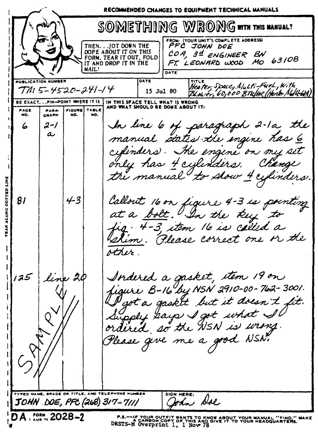
191
192
193
194 The Metric System and Equivalents Linear Measure 1 centimeter = 10 millimeters =.39 inch 1 decimeter= 10 centimeters = 3.94 inches 1 meter = 10 decimeters = inches 1 dekameter = 10 Meters = 32.8 feet 1 hectometer = 10 dekameters = feet 1 kilometer = 10 hectometers = feet Weights 1 centigram = 10 milligrams =.15 grain 1 decigram = 10 centigrams = 1.54 grains 1 gram = 10 decigram = 0.35 ounce 1 dekagram = 10 Grams =.35 ounce 1 hectogram = 10 dekagrams = 3.52 ounces 1 kilogram = 10 hectograms = 2.2 pounds 1 quintal = 100 kilograms = pounds 1 metric ton = 10 quintals = 1.1 short tons Liquid Measure 1 centiliter = 10 milliliters =.34 fluid ounce 1 deciliter = 10 centiliters = 3.38 fluid ounces 1 liter = 10 deciliters = fluid ounces 1 dekaliter = 10 liters = 2.64 gallons 1 hectoliter = 10 dekaliters = gallons 1 kiloliter = 10 hectoliters = gallons Square Measure 1 sq. centimeter = 100 sq millimeters =.155 sq. inch 1 sq. decimeter= 100 sq centimeters = 15.5 sq. inches 1 sq. meter (centare) = 100 sq decimeters = sq. feet 1 sq. dekameter (are) = 100 sq. meters = 1,076.4 sq. feet 1 sq. hectometer (hectare) = 100 sq. dekameters = 2.47 acres 1 sq. kilometer = 100 sq. hectometers =.386 sq. mile Cubic Measure 1 cu. centimeter = 1000 cu. millimeters = 06 cu. inch 1 cu. decimeter = 1000 cu. decimeters = cu. inches 1 cu. meter = 1000 cu. decimeters = cu. feet Approximate Conversion Factors To change To Multiply by To change To Multiply by inches centimeters feet meters.305 yards meters.914 miles kilometers square inches square centimeters square feet square meters.093 square yards square meters.836 square miles square kilometers acres square hectometers.405 cubic feet cubic meters.028 cubic yards cubic meters.765 fluid ounces milliliters 29,573 pints liters.473 quarts liters.946 gallons liters ounces grams pounds kilograms.454 short tons metric tons.907 pound-feet newton-meters pounds-inches newton-meters ounce-inches newton-meters centimeters inches.394 meters feet meters yards kilometers miles.621 square centimeters square inches.155 square meters square feet square meters square yards square kilometers square miles.386 square hectometers acres cubic meters cubic feet cubic meters cubic yards milliliters fluid ounces.034 liters pints liters quarts liters gallons.264 grams ounces.035 kilograms pounds metric tons short tons Temperature (Exact) F Fahrenheit 5/9 (after Celsius C temperature subtracting 32) temperature
195 PIN:

196 This fine document... Was brought to you by me: Liberated Manuals -- free army and government manuals Why do I do it? I am tired of sleazy CD-ROM sellers, who take publicly available information, slap watermarks and other junk on it, and sell it. Those masters of search engine manipulation make sure that their sites that sell free information, come up first in search engines. They did not create it... They did not even scan it... Why should they get your money? Why are not letting you give those free manuals to your friends? I am setting this document FREE. This document was made by the US Government and is NOT protected by Copyright. Feel free to share, republish, sell and so on. I am not asking you for donations, fees or handouts. If you can, please provide a link to liberatedmanuals.com, so that free manuals come up first in search engines: <A HREF= Military and Government Manuals</A> Sincerely Igor Chudov Chicago Machinery Movers
TECHNICAL MANUAL OPERATOR'S, ORGANIZATIONAL, DIRECT AND GENERAL SUPPORT MAINTENANCE MANUAL
 TECHNICAL MANUAL OPERATOR'S, ORGANIZATIONAL, DIRECT AND GENERAL SUPPORT MAINTENANCE MANUAL HEATER, SPACE, MULTI-FUEL, WITH BLOWER, 6,000 BTU/HR (HUNTER MODEL UH-68F) NSN 4520-01-050-5628 This copy is a
TM NOVEMBER 1986 HEATER, SPACE, MULTIFUEL WITH BLOWER, 60,000 BTU/HR, 120 V UH-68G ( )
") OPERATOR S, UNIT, AND INTERMEDIATE MAINTENANCE MANUAL TABLE OF CONTENTS i OPERATING INSTRUCTIONS 2-1 UNIT MAINTENANCE INSTRUCTIONS 3-1 INTERMEDIATE MAINTENANCE INSTRUCTIONS 4-1 MAINTENANCE ALLOCATION CHART
OPERATOR S, UNIT, AND INTERMEDIATE MAINTENANCE MANUAL TABLE OF CONTENTS i OPERATING INSTRUCTIONS 2-1 UNIT MAINTENANCE INSTRUCTIONS 3-1 INTERMEDIATE MAINTENANCE INSTRUCTIONS 4-1 MAINTENANCE ALLOCATION CHART
*TM Operator s, Unit, Direct Support, and General Support Maintenance Manual TECHNICAL MANUAL
 *TM 9-4520-251-14 TECHNICAL MANUAL Operator s, Unit, Direct Support, and General Support Maintenance Manual HEATER, DUCT TYPE, PORTABLE, TRAILER MOUNTED, 400,000 BTU/HR MODEL PH-400-G NSN 4520-01-136-2139
HEADQUARTERS, DEPARTMENT OF THE ARMY AND THE AIR FORCE 5 AUGUST 1988
 ARMY TM 5-4520-256-14 AIR FORCE T.O. 35E7-6-26-1 OPERATOR S, UNIT, INTERMEDIATE DIRECT SUPPORT AND INTERMEDIATE GENERAL SUPPORT MAINTENANCE HEATER, DUCT TYPE, PORTABLE, HDU-36/E, 120,000 BTU, MODEL H82
HEADQUARTERS, DEPARTMENT OF ARMY
 OPERATING INSTRUCTIONS 2-1 TM 9-4520-260-13 TECHNICAL MANUAL OPERATOR S, UNIT, AND DIRECT SUPPORT MAINTENANCE MANUAL OPERATOR PREVENTIVE MAINTENANCE CHECKS AND SERVICES 2-4 OPERTOR MAINTENANCE INSTRUCTIONS
HEATER, DUCT TYPE, PORTABLE, TRAILER MOUNTED, 400,000 BTU/HR FlESTA MODEL FC OPERATOR S, ORGANIZATIONAL, DIRECT SUPPORT AND GENERAL SUPPORT
 T M 5-4 5 2 0-2 4 4-1 4 OPERATOR S, ORGANIZATIONAL, DIRECT SUPPORT AND GENERAL SUPPORT MAINTENANCE MANUAL TABLE OF CONTENTS EQUIPMENT DESCRIPTION OPERATING INSTRUCTIONS OPERATOR S MAINTENANCE ORGANIZATIONAL
DEPARTMENT OF THE ARMY TECHNICAL MANUAL TECHNICAL MANUAL
 DEPARTMENT OF THE ARMY TECHNICAL MANUAL TM 5-4520-235-13 TECHNICAL MANUAL OPERATOR, ORGANIZATIONAL AND DIRECT SUPPORT MAINTENANCE MANUAL INCLUDING REPAIR PARTS AND SPECIAL TOOLS LIST HEATER, SPACE, OIL
OPERATING INSTRUCTIONS 2-1 OPERATOR PREVENTIVE MAINTENANCE CHECKS AND SERVICES (PMCS) 2-5 OPERATOR TROUBLESHOOTING 3-1
 2-5 OPERATOR TROUBLESHOOTING 3-1") TECHNICAL MANUAL TM 9-4120-402-14 OPERATOR'S, UNIT, DIRECT SUPPORT, AND GENERAL SUPPORT MAINTENANCE MANUAL OPERATING INSTRUCTIONS 2-1 OPERATOR PREVENTIVE MAINTENANCE CHECKS AND SERVICES (PMCS) 2-5 OPERATOR
TECHNICAL MANUAL TM 9-4120-402-14 OPERATOR'S, UNIT, DIRECT SUPPORT, AND GENERAL SUPPORT MAINTENANCE MANUAL OPERATING INSTRUCTIONS 2-1 OPERATOR PREVENTIVE MAINTENANCE CHECKS AND SERVICES (PMCS) 2-5 OPERATOR
DEPARTMENT OF THE ARMY TECHNICAL MANUAL (FSN ) This copy is a reprint which includes current pages from Changes 1 through 3.
 This copy is a reprint which includes current pages from Changes 1 through 3.") TM 5-4120-239-14 DEPARTMENT OF THE ARMY TECHNICAL MANUAL TECHNICAL MANUAL OPERATOR, ORGANIZATIONAL, DIRECT SUPPORT AND GENERAL SUPPORT MAINTENANCE MANUAL AIR CONDITIONER, HORIZONTAL COMPACT, 9,000 BTU
TM 5-4120-239-14 DEPARTMENT OF THE ARMY TECHNICAL MANUAL TECHNICAL MANUAL OPERATOR, ORGANIZATIONAL, DIRECT SUPPORT AND GENERAL SUPPORT MAINTENANCE MANUAL AIR CONDITIONER, HORIZONTAL COMPACT, 9,000 BTU
AIR CONDITIONER, HORIZONTAL, COMPACT, BTUH
 TECHNICAL MANUAL OPERATOR S ORGANIZATIONAL, DIRECT SUPPORT & GENERAL SUPPORT MAINTENANCE MANUAL FOR AIR CONDITIONER, HORIZONTAL, COMPACT, 36000 BTUH 208 VOLT, 3 PHASE 400 HERTZ NSN 4120-00-063-8182 AMERICAN
AIR CONDITIONER, HORIZONTAL, 9,000 BTU/HR
 TECHNICAL MANUAL OPERATOR, ORGANIZATIONAL, AND DIRECT SUPPORT MAINTENANCE MANUAL AIR CONDITIONER, HORIZONTAL, 9,000 BTU/HR A.R.E. MANUFACTURING CO., INC. MODEL FM9000 NSN 4120-01-125-3947 HEADQUARTERS,
DEPARTMENT OF THE ARMY TECHNICAL MANUAL
 This copy is a reprint which includes current pages from Changes 1 through 10. TM 5-4120-243-14 DEPARTMENT OF THE ARMY TECHNICAL MANUAL TECHNICAL MANUAL OPERATOR, ORGANIZATIONAL, DIRECT SUPPORT AND GENERAL
DEPARTMENT OF THE ARMY TECHNICAL MANUAL TECHNICAL MANUAL OPERATOR, ORGANIZATIONAL, DIRECT SUPPORT AND GENERAL SUPPORT MAINTENANCE MANUAL
 TM 10-4520-201-14 DEPARTMENT OF THE ARMY TECHNICAL MANUAL TECHNICAL MANUAL OPERATOR, ORGANIZATIONAL, DIRECT SUPPORT AND GENERAL SUPPORT MAINTENANCE MANUAL HEATER, DUCT - TYPE; PORTABLE; GASOLINE; 250,000
HEADQUARTERS, DEPARTMENT OF THE ARMY 25 FEBRUARY 1982
 TECHNICAL MANUAL OPERATOR'S, ORGANIZATIONAL, DIRECT SUPPORT, AND GENERAL SUPPORT MAINTENANCE MANUAL CHAPTER/ APPENDIX INTRODUCTION 1 OPERATING INSTRUCTIONS 2 ORGANIZATIONAL MAINTENANCE INSTRUCTIONS 3 DIRECT
IMPORTANT SAFETY INFORMATION! WARNING ALWAYS keep electric cords, home furnishings, drapes, clothing, papers, or other combustibles at least 3 feet (0
 Electric Fireplace Factory Model: EF-30D CONSUMER SAFETY INFORMATION Read this manual before installing and operating this appliance Failure to follow these instructions may result in electric shock, fire
UHIR Series. Horizontal or Vertical Mounting Industrial / Commercial Electric Unit Heater. Owner s Manual
 UHIR Series Horizontal or Vertical Mounting Industrial / Commercial Electric Unit Heater Owner s Manual This manual covers installation, maintenance and repair parts. Read carefully before attempting to
IMPORTANT INSTRUCTIONS READ & SAVE
 5000W Ceiling/Wall Mounted Garage Heater OWNER S MANUAL Model: PH-950N IMPORTANT INSTRUCTIONS READ & SAVE PET OWNERS WARNING: The health of some small pets including birds are extremely sensitive to the
EL195UHE SERIES GAS FURNACE WARNING WARNING
 2012 Lennox Industries Inc. Dallas, Texas, USA 506737-01 12/2012 Supersedes 06/2011 EL195UHE SERIES GAS FURNACE Improper installation, adjustment, alteration, service or maintenance can cause property
USER S INFORMATION MANUAL
 USER S INFORMATION MANUAL UPFLOW/HORIZONTAL & DOWNFLOW TWO STAGE INDUCED DRAFT GAS FURNACES Recognize this symbol as an indication of Important Safety Information If the information in this manual is not
USER S INFORMATION MANUAL
 2017 Lennox Industries Inc. Dallas, Texas, USA 506737-01 04/2017 Supersedes 03/2017 USER S INFORMATION MANUAL EL195UHE SERIES GAS FURNACE Improper installation, adjustment, alteration, service or maintenance
G61MPV SERIES GAS FURNACE WARNING
 2003 Lennox Industries Inc. Dallas, Texas, USA 504,809M 03/2009 Supersedes 06/2003 G61MPV SERIES GAS FURNACE Litho U.S.A. FIRE OR EXPLOSION HAZARD. Failure to follow safety warnings exactly could result
NO VENTING REQUIRED 120V AC;
 ELECTRIC FIREPLACE Model Number: Alice (EF172B-EF176B) OWNER S MANUAL WARNING Read and understand this entire owner s manual, including all safety information, before plugging in or using this product.
EL296UHV SERIES GAS FURNACE WARNING WARNING
 2011 Lennox Industries Inc. Dallas, Texas, USA 506769 01 08/2012 Supersedes 10/2011 EL296UHV SERIES GAS FURNACE Improper installation, adjustment, alteration, service or maintenance can cause property
EL195UH SERIES GAS FURNACE WARNING
 2010 Lennox Industries Inc. Dallas, Texas, USA 506597 01 11/2010 EL195UH SERIES GAS FURNACE Litho U.S.A. FIRE OR EXPLOSION HAZARD. Failure to follow safety warnings exactly could result in serious injury,
EL195DFE SERIES GAS FURNACE WARNING
 2011 Lennox Industries Inc. Dallas, Texas, USA 506739 01 06/2011 EL195DFE SERIES GAS FURNACE Litho U.S.A. FIRE OR EXPLOSION HAZARD. Failure to follow safety warnings exactly could result in serious injury,
TECHNICAL MANUAL OPERATOR'S, ORGANIZATIONAL, DIRECT SUPPORT AND GENERAL SUPPORT MAINTENANCE MANUAL
 TECHNICAL MANUAL OPERATOR'S, ORGANIZATIONAL, DIRECT SUPPORT AND GENERAL SUPPORT MAINTENANCE MANUAL LANDING CRAFT UTILITY LCU 1667-1670 NSN 1905-01-168-5764 OPERATOR MAINTENANCE INSTRUCTIONS FOR AUXILIARY
Operator's, Unit, Direct Support and General Support Maintenance Manual
 Operator's, Unit, Direct Support and General Support Maintenance Manual * INTRODUCTION PAGE 1-1 OPERATING INSTRUCTIONS PAGE 2-1 OPERATOR MAINTENANCEPAGE PAGE 3-1 UNIT MAINTENANCE P PAGE 4-1 DIRECT SUPPORT
TM TO 34W
 TM 5-3431-228-14 TO 34W4-102-1 TECHNICAL MANUAL OPERATOR, ORGANIZATIONAL, DIRECT SUPPORT AND GENERAL SUPPORT MAINTENANCE MANUAL WELDING MACHINE, ARC: AC/DC, 300 AMP, TRANSFORMER RECTIFIER; CONSTANT CURRENT,
USER'S MANUAL PGE Single Package Rooftop
 USER'S MANUAL PGE Single Package Rooftop Gas Heating/Electric Cooling Units Sizes 036-150 3 to 12-1/2 Tons NOTE TO INSTALLER: This manual should be left with the equipment owner. WARNING: If the information
TM LANDING CRAFT, UTILITY (LCU) BASIC CRAFT UNIT, INTERMEDIATE DIRECT SUPPORT AND INTERMEDIATE GENERAL MAINTENANCE INSTRUCTIONS
 BASIC CRAFT UNIT, INTERMEDIATE DIRECT SUPPORT AND INTERMEDIATE GENERAL MAINTENANCE INSTRUCTIONS") TECHNICAL MANUAL UNIT, INTERMEDIATE DIRECT SUPPORT AND INTERMEDIATE GENERAL SUPPORT MAINTENANCE INSTRUCTIONS LANDING CRAFT, UTILITY (LCU) NSN 1905-01-154-1191 BASIC CRAFT (PART I) This, copy is a reprint
TECHNICAL MANUAL UNIT, INTERMEDIATE DIRECT SUPPORT AND INTERMEDIATE GENERAL SUPPORT MAINTENANCE INSTRUCTIONS LANDING CRAFT, UTILITY (LCU) NSN 1905-01-154-1191 BASIC CRAFT (PART I) This, copy is a reprint
238 Series. Industrial/Commercial Electric Unit Heater. Owner s Manual
 238 Series Industrial/Commercial Electric Unit Heater Owner s Manual This manual covers installation, operation and maintenance. Read carefully before attempting to install, operate or service the 238
ML180UH SERIES GAS FURNACE WARNING WARNING
 2017 Lennox Industries Inc. Dallas, Texas, USA 506525-01 04/2017 Supersedes 10/2015 ML180UH SERIES GAS FURNACE Improper installation, adjustment, alteration, service or maintenance can cause property damage,
P.O. Box , Dallas, TX USER'S INFORMATION MANUAL Single-Stage Warm Air Gas Furnaces
 P.O. Box 799900, Dallas, TX 75379-9900 USER'S INFORMATION MANUAL Single-Stage Warm Air Gas Furnaces This is a safety alert symbol and should never be ignored. When you see this symbol on labels or in manuals,
OWNER S MANUAL. FLAT PANEL FIREPLACE HEATER Model Number: Serena (EF202A) WARNING CAUTION
 WARNING CAUTION") FLAT PANEL FIREPLACE HEATER Model Number: Serena (EF202A) OWNER S MANUAL WARNING Read and understand this entire owner s manual, including all safety information, before plugging in or using this product.
FLAT PANEL FIREPLACE HEATER Model Number: Serena (EF202A) OWNER S MANUAL WARNING Read and understand this entire owner s manual, including all safety information, before plugging in or using this product.
Patio Heater_ _V4_ENG.book Page 1 Tuesday, September 2, :00 AM. AmazonBasics Patio Heater B00LILH3V4 B00LILH47C B010VFKZEO
 Patio Heater_14-0979_V4_ENG.book Page 1 Tuesday, September 2, 2014 10:00 AM AmazonBasics Patio Heater B00LILH3V4 B00LILH47C B010VFKZEO Patio Heater_14-0979_V4_ENG.book Page 2 Tuesday, September 2, 2014
ELECTRIC FLAT PANEL FIREPLACE HEATER
 ELECTRIC FLAT PANEL FIREPLACE HEATER Model Numbers: 80-2000A-42 OWNER S MANUAL AC 120V 60Hz 1500W WARNING Read and understand this entire owner s manual, including all safety information, before plugging
PROAIR Air Conditioner. CR29 Model INSTRUCTION MANUAL nvent Rev. I P/N
 PROAIR Air Conditioner CR29 Model INSTRUCTION MANUAL Rev. I P/N 89104461 TABLE OF CONTENTS Warranty and Return Policy...2 RECEIVING THE AIR CONDITIONER...3 HANDLING AND TESTING THE AIR CONDITIONER...3
SLP98UH SERIES VARIABLE CAPACITY GAS FURNACE WARNING WARNING
 2015 Lennox Industries Inc. Dallas, Texas, USA 506443-01 01/2015 Supersedes 08/2012 SLP98UH SERIES VARIABLE CAPACITY GAS FURNACE Improper installation, adjustment, alteration, service or maintenance can
AmazonBasics Patio Heater B00LILH3V4 B00LILH47C B010VFKZEO
 AmazonBasics Patio Heater B00LILH3V4 B00LILH47C B010VFKZEO English......................5 2 Safety and compliance 3 4 English Instruction Manual English Patio Heater Contents Make sure that the package
Packaged Gas/Electric Units. Owner s Guide to Operating and Maintaining Your Gas/Electric Unit
 Packaged Gas/Electric Units Owner s Guide to Operating and Maintaining Your Gas/Electric Unit ELECTRICAL SHOCK HAZARD. FIRE OR EXPLOSION HAZARD Disconnect power at fuse box or service panel before performing
USER S, MAINTENANCE and SERVICE INFORMATION MANUAL
 CONTENTS SAFETY INFORMATION................ 2 FOR YOUR SAFETY...................... 2 SYSTEM OPERATION.................. 2 THERMOSTATS.......................... 2 INTERMITTENT IGNITION DEVICE..........
Wall Mount Electric Fireplace
 Wall Mount Electric Fireplace User Guide Thank you for purchasing the Ivation Wall Mount Electric Fireplace. This User Guide is intended to provide you with guidelines to ensure that operation of this
72 ONYX XL FLAT PANEL ELECTRIC FIREPLACE
 72 ONYX XL FLAT PANEL ELECTRIC FIREPLACE Model Numbers: 80005 OWNER S MANUAL WARNING Read and understand this entire owner s manual, including all safety information, before plugging in or using this product.
S150 S300 CONSTRUCTION HEATERS. Rev: August 15, 2008 SERVICE AND MAINTENANCE MANUAL No PLEASE RETAIN FOR FUTURE REFERENCE PRODUCTS
 S150 & S300 CONSTRUCTION HEATERS Rev: 2.7.2 August 15, 2008 SERVICE AND MAINTENANCE MANUAL No. 934-6637 PLEASE RETAIN FOR FUTURE REFERENCE PRODUCTS A DIVISION OF HAUL-ALL EQUIPMENT LTD. 4115-18 Avenue
USER S INFORMATION MANUAL
 USER S INFORMATION MANUAL UPFLOW & DOWNFLOW/HORIZONTAL CONDENSING GAS FURNACES SAFETY Recognize this symbol as an indication of Important Safety Information If not installed, operated and maintained in
OWNER S MANUAL ELECTRIC FIREPLACE INSERT. Model No.: WESTERN (EF42D-45D) WARNING CAUTION
 WARNING CAUTION") ELECTRIC FIREPLACE INSERT Model No.: WESTERN (EF42D-45D) OWNER S MANUAL WARNING Read and understand this entire owner s manual, including all safety information, before plugging in or using this product.
ELECTRIC FIREPLACE INSERT Model No.: WESTERN (EF42D-45D) OWNER S MANUAL WARNING Read and understand this entire owner s manual, including all safety information, before plugging in or using this product.
SPECIFICATIONS PART NAME
 SPECIFICATIONS MODEL High HEAT RATING Low FUEL TANK CAPACITY BURNING TIME DIMENSIONS(W x D x H) WEIGHT VOLTAGE / FREQUENCY ELECTRICAL CONSUMPTION LC-S27 9,900 BTU / 2.9 kw 2,900 BTU / 0.8 kw 4.0 lit. 14.2~
IMPORTANT INSTRUCTIONS READ & SAVE
 WALL/CEILING MOUNT HEATER OWNER S MANUAL Model No.: DR-966 6000W 240V 60HZ IMPORTANT INSTRUCTIONS READ & SAVE 1 TABLE OF CONTENTS Important Instructions.. 3 Specifications and Wiring Diagram 5 Parts of
IMPORTANT INSTRUCTIONS READ & SAVE
 5,000W/240V WALL / CEILING MOUNTED GARAGE HEATER WITH ELECTRONIC CONTROLLER AND REMOTE OWNER S MANUAL IMPORTANT INSTRUCTIONS READ & SAVE Model: PH-950NR PET OWNERS WARNING: The health of some small pets
GAS RACK OVENS WITH ELECTRONIC OVEN CONTROL
 GAS RACK OVENS WITH ELECTRONIC OVEN CONTROL MODELS DRO2G DRO2GH GAS GAS 701 S. RIDGE AVENUE TROY, OHIO 45374-0001 937-332-3000 www.hobartcorp.com FORM 19202 Rev. D (Dec. 2003) IMPORTANT FOR YOUR SAFETY
T-SERIES Air Conditioner. T20 Model INSTRUCTION MANUAL nvent Rev. C P/N
 T-SERIES Air Conditioner T20 Model INSTRUCTION MANUAL Rev. C P/N 89114993 TABLE OF CONTENTS Warranty and Return Policy... 2 IMPORTANT NOTICE... 2 RECEIVING THE AIR CONDITIONER... 3 HANDLING AND TESTING
PROAIR Air Conditioner. CR23 Model INSTRUCTION MANUAL nvent Rev. D P/N
 PROAIR Air Conditioner CR23 Model INSTRUCTION MANUAL Rev. D P/N 89112522 TABLE OF CONTENTS Warranty and Return Policy...2 RECEIVING THE AIR CONDITIONER...3 HANDLING AND TESTING THE AIR CONDITIONER...3
USER S, MAINTENANCE and SERVICE INFORMATION MANUAL
 CONTENTS SAFETY INFORMATION................ 2 FOR YOUR SAFETY....................... 2 SYSTEM OPERATION.................. 2 THERMOSTATS.......................... 2 INTERMITTENT IGNITION DEVICE...........
OWNER S MANUAL ELECTRIC FLAT PANEL FIREPLACE. AC V 60Hz. Model# : /60 - Built-in & Wall Mounted Electric Fireplace WARNING CAUTION
 ELECTRIC FLAT PANEL FIREPLACE Model# :80017 OWNER S MANUAL 50/60 - Built-in & Wall Mounted Electric Fireplace AC 110-120V 60Hz WARNING Read and understand this entire owner s manual, including all safety
Multi-Function Cooktop
 INSTALLATION GUIDE Multi-Function Cooktop Contents Wolf Multi-Function Cooktop.................... 3 Multi-Function Cooktop Specifications............ 4 Multi-Function Cooktop Installation...............
SPECTRACOOL Air Conditioner. N21 Model INSTRUCTION MANUAL nvent Rev. G P/N
 SPECTRACOOL Air Conditioner N21 Model INSTRUCTION MANUAL Rev. G P/N 89115088 TABLE OF CONTENTS WARRANTY AND RETURN POLICY...2 RECEIVING THE AIR CONDITIONER...3 HANDLING AND TESTING THE AIR CONDITIONER...3
INSTALLATION GUIDE Dual Fuel Ranges
 INSTALLATION GUIDE Dual Fuel Ranges Contents Wolf Dual Fuel Ranges......................... 3 Safety Instructions............................ 4 Dual Fuel Range Specifications.................. 5 Dual Fuel
THC 85N / 175N INDUSTRIAL / COMMERCIAL SPACE HEATER
 THC 85N / 175N INDUSTRIAL / COMMERCIAL SPACE HEATER Certified to / Certifié à CGA 2.14 M2000 Conforms to / Conforme à ANSI std Z83.7 2000 Suitable for indoor or outdoor installation / Unvented / Unattended
TECHNICAL MANUAL OPERATOR, UNIT, DIRECT SUPPORT AND GENERAL SUPPORT MAINTENANCE MANUAL (INCLUDING REPAIR PARTS AND SPECIAL TOOLS LIST) FOR
 FOR") *TM 55-1930-209-14&P-17 TECHNICAL MANUAL OPERATOR, UNIT, DIRECT SUPPORT AND GENERAL SUPPORT MAINTENANCE MANUAL (INCLUDING REPAIR PARTS AND SPECIAL TOOLS LIST) FOR WATER PURIFICATION BARGES (NSN 1930-01-234-2165)
*TM 55-1930-209-14&P-17 TECHNICAL MANUAL OPERATOR, UNIT, DIRECT SUPPORT AND GENERAL SUPPORT MAINTENANCE MANUAL (INCLUDING REPAIR PARTS AND SPECIAL TOOLS LIST) FOR WATER PURIFICATION BARGES (NSN 1930-01-234-2165)
T-Series Air Conditioner T20 Model
 INSTRUCTION MANUAL T-Series Air Conditioner T20 Model Protecting Electronics. Exceeding Expectations. McLean Cooling Technology 11611 Business Park Blvd N Champlin, MN 55316 USA Tel 763-323-8200 Fax 763-576-3200
THC- 355DF (Dual Fuel)
") OPERATING INSTRUCTIONS MANUAL THC- 355DF (Dual Fuel) INDUSTRIAL / COMMERCIAL DIRECTIONAL SPACE HEATER (OPERATOR MUST RETAIN FOR FUTURE REFERENCES) Certified to / Certifié à ANSI std Z83.7 2000 Suitable
OPERATING INSTRUCTIONS MANUAL THC- 355DF (Dual Fuel) INDUSTRIAL / COMMERCIAL DIRECTIONAL SPACE HEATER (OPERATOR MUST RETAIN FOR FUTURE REFERENCES) Certified to / Certifié à ANSI std Z83.7 2000 Suitable
HEATER, DUCT TYPE, PORTABLE, TRAILER MOUNTED, 400,000 BTU/HR FlESTA MODEL FC OPERATOR S, ORGANIZATIONAL, DIRECT SUPPORT AND GENERAL SUPPORT
 T M 5-4 5 2 0-2 4 4-1 4 OPERATOR S, ORGANIZATIONAL, DIRECT SUPPORT AND GENERAL SUPPORT MAINTENANCE MANUAL TABLE OF CONTENTS EQUIPMENT DESCRIPTION OPERATING INSTRUCTIONS OPERATOR S MAINTENANCE ORGANIZATIONAL
PROAIR Air Conditioner. CR43 Model INSTRUCTION MANUAL nvent Rev. H P/N
 PROAIR Air Conditioner CR43 Model INSTRUCTION MANUAL Rev. H P/N 10-1008-130 TABLE OF CONTENTS Warranty and Return Policy...2 RECEIVING THE AIR CONDITIONER...3 HANDLING AND TESTING THE AIR CONDITIONER...3
OPERATING INSTRUCTIONS AND OWNER S MANUAL
 OPERATING INSTRUCTIONS AND OWNER S MANUAL MR. HEATER READ INSTRUCTIONS CAREFULLY: Read and follow all instructions. Place instructions in a safe place for future reference. Do not allow anyone who has
TECHNICAL MANUAL OPERATOR S, ORGANIZATIONAL, DIRECT SUPPORT AND GENERAL SUPPORT MAINTENANCE MANUAL IINCLUDING REPAIR PARTS AND SPECIAL TOOLS LISTI FOR
 TM 5-4210-222-14&P-3 TECHNICAL MANUAL OPERATOR S, ORGANIZATIONAL, DIRECT SUPPORT AND GENERAL SUPPORT MAINTENANCE MANUAL IINCLUDING REPAIR PARTS AND SPECIAL TOOLS LISTI FOR TRUCK, FIREFIGHTIN6G DRY CHEMICAL
USER S INFORMATION MANUAL
 USER S INFORMATION MANUAL UPFLOW, DOWNFLOW, UPFLOW/HORIZONTAL & HORIZONTAL ONLY INDUCED DRAFT GAS FURNACES Recognize this symbol as an indication of Important Safety Information If the information in this
THC 85N / 175N INDUSTRIAL / COMMERCIAL SPACE HEATER
 THC 85N / 175N INDUSTRIAL / COMMERCIAL SPACE HEATER Certified to / Certifié à CGA 2.14 M2000 Conforms to / Conforme à ANSI std Z83.7 2000 Suitable for indoor or outdoor installation / Unvented / Unattended
DIESEL/PARAFFIN HEATERS
 DIESEL/PARAFFIN HEATERS MODEL NO: XR80, XR110, XR160, XR210 PART NO: 6931004, 6931006, 6931008, 6931012 OPERATION & MAINTENANCE INSTRUCTIONS LS0814 INTRODUCTION Thank you for purchasing this CLARKE product.
TECHNICAL MANUAL OPERATOR S MANUAL FOR MULTIPLE INTEGRATED LASER ENGAGEMENT SYSTEM (MILES) SIMULATOR SYSTEM, FIRING, LASER: M78 NSN
 SIMULATOR SYSTEM, FIRING, LASER: M78 NSN") TECHNICAL MANUAL OPERATOR S MANUAL FOR MULTIPLE INTEGRATED LASER ENGAGEMENT SYSTEM (MILES) SIMULATOR SYSTEM, FIRING, LASER: M78 NSN 1270-01-159-0482 FOR OH-58 OBSERVATION HELICOPTER HEADQUARTERS, DEPARTMENT
TECHNICAL MANUAL OPERATOR S MANUAL FOR MULTIPLE INTEGRATED LASER ENGAGEMENT SYSTEM (MILES) SIMULATOR SYSTEM, FIRING, LASER: M78 NSN 1270-01-159-0482 FOR OH-58 OBSERVATION HELICOPTER HEADQUARTERS, DEPARTMENT
WARNING FIRE OR EXPLOSION HAZARD.
 2017 Lennox Industries Inc. Dallas, Texas, USA 506897-01 04/2017 Supersedes 10/2015 EL280DF SERIES GAS FURNACE Improper installation, adjustment, alteration, service or maintenance can cause property damage,
Gallery Electric Fireplaces
 Gallery Electric Fireplaces Homeowner s Installation Instructions & Operating Manual Model: GBI-34, GBI-41 Only use this heater as described in this manual. Any other use is not recommended by the manufacturer,
T-Series Air Conditioner T15 Model
 INSTRUCTION MANUAL T-Series Air Conditioner T15 Model Protecting Electronics. Exceeding Expectations. McLean Cooling Technology 11611 Business Park Blvd N Champlin, MN 55316 USA Tel 763-323-8200 Fax 763-576-3200
GENESIS Air Conditioners. All Models INSTRUCTION MANUAL nvent Rev. K P/N
 GENESIS Air Conditioners All Models INSTRUCTION MANUAL Rev. K P/N 89104462 TABLE OF CONTENTS Warranty and Return Policy...2 RECEIVING THE AIR CONDITIONER...3 HANDLING AND TESTING THE AIR CONDITIONER...3
User s Manual WS-63TB36SS WS-63TB42SS NOTE: PLEASE INSPECT HOOD IMMEDIATELY UPON RECEIVING. CLAIM OF DAMAGE AFTER 7 DAYS OF DELIVERY WILL BE DENIED.
 www.windsterhood.com User s Manual WS-63TB36SS WS-63TB42SS ISLAND SERIES NOTE: PLEASE INSPECT HOOD IMMEDIATELY UPON RECEIVING. CLAIM OF DAMAGE AFTER 7 DAYS OF DELIVERY WILL BE DENIED. This unit is designed
TECHNICAL MANUAL UNIT, INTERMEDIATE DIRECT SUPPORT AND INTERMEDIATE GENERAL SUPPORT MAINTENANCE MANUAL (INCLUDING REPAIR PARTS AND SPECIAL TOOLS LIST)
") TM 55-1925-227-24&P TECHNICAL MANUAL UNIT, INTERMEDIATE DIRECT SUPPORT AND INTERMEDIATE GENERAL SUPPORT MAINTENANCE MANUAL (INCLUDING REPAIR PARTS AND SPECIAL TOOLS LIST) FIRE FIGHTING SYSTEM FOR LARGE
TM 55-1925-227-24&P TECHNICAL MANUAL UNIT, INTERMEDIATE DIRECT SUPPORT AND INTERMEDIATE GENERAL SUPPORT MAINTENANCE MANUAL (INCLUDING REPAIR PARTS AND SPECIAL TOOLS LIST) FIRE FIGHTING SYSTEM FOR LARGE
THC 85 / 175 INDUSTRIAL / COMMERCIAL SPACE HEATER
 THC 85 / 175 INDUSTRIAL / COMMERCIAL SPACE HEATER Certified to / Certifié à CGA 2.14 M2000 Conforms to / Conforme à ANSI std Z83.7 2000 Suitable for indoor or outdoor installation / Unvented / Unattended
T-SERIES Air Conditioner. T29 Model INSTRUCTION MANUAL nvent Rev. I P/N
 T-SERIES Air Conditioner T29 Model INSTRUCTION MANUAL Rev. I P/N 89104464 TABLE OF CONTENTS Warranty and Return Policy...2 IMPORTANT NOTICE...2 RECEIVING THE AIR CONDITIONER...3 HANDLING AND TESTING THE
WARNING FIRE OR EXPLOSION HAZARD.
 2017 Lennox Industries Inc. Dallas, Texas, USA 506698-01 04/2017 Supersedes 10/2015 SL280DFV SERIES GAS FURNACE Improper installation, adjustment, alteration, service or maintenance can cause property
PVE SERIES POWER VENTER SYSTEM MANUAL
 PVE SERIES POWER VENTER SYSTEM MANUAL Contents Page I. Typical Venting System Components 2 II. System Operation 3 III. Power Venter Sizing 3,4 IV. Installation Safety Instructions 5,6 V. Installation of
T-SERIES Air Conditioner. T43 Model INSTRUCTION MANUAL nvent Rev. I P/N
 T-SERIES Air Conditioner T43 Model INSTRUCTION MANUAL Rev. I P/N 10-1008-145 TABLE OF CONTENTS Warranty and Return Policy...2 IMPORTANT NOTICE...2 RECEIVING THE AIR CONDITIONER...3 HANDLING AND TESTING
User s Information Manual
 48AJ,AK,AW,AY020-060 Single-Package Rooftop Gas Heating Units with COMFORTLINK Controls and Scroll Compressors User s Information Manual NOTE TO INSTALLER This manual should be left with the equipment
PARAFFIN/DIESEL HEATER
 PARAFFIN/DIESEL HEATER MODEL NO: XR60 PART NO: 6931002 OPERATION & MAINTENANCE INSTRUCTIONS LS0813 INTRODUCTION Thank you for purchasing this CLARKE product. Before attempting to use this product, please
IMPORTANT INSTRUCTIONS READ & SAVE
 7,500W/240V WALL / CEILING MOUNTED GARAGE HEATER OWNER S MANUAL Model: DR-975 7500W 240V 60Hz IMPORTANT INSTRUCTIONS READ & SAVE 1 TABLE OF CONTENTS Important Instructions. 3 Installation Instructions...
SERVICE FACTS WARNING M801-SF-1C. Gas Furnaces Upflow & Downflow Induced Draft 1 Stage Heat Models: DISCONNECT POWER BEFORE SERVICING M801P040AU24AA
 SERVICE FACTS Gas Furnaces Upflow & Downflow Induced Draft Stage Heat Models: M80P00AU2AA M80P060AU2AA M80P060AU36AA M80P080BU36AA M80P080BU8AA M80P00BU36AA M80P00CU8AA M80P00CU60AA M80PDU60AA M80P0DU60AA
Flat Wall Mounted / Free stand Electric Fireplace. Model Numbers: S OWNER S MANUAL. Wall Hanging Mode. Freestanding Mode AC 120V / 60HZ 1500W
 Flat Wall Mounted / Free stand Electric Fireplace Model Numbers: 80-421S OWNER S MANUAL Wall Hanging Mode Freestanding Mode AC 120V / 60HZ 1500W WARNING Read and understand this entire owner s manual,
HI Industrial Utility Heater HI Soleus Air International
 HI1-50-03 Industrial Utility Heater HI1-50-03 2010 Soleus Air International Thank you for choosing a Soleus Air Utility Heater. This owner s manual will provide you with valuable information necessary
OPERATING INSTRUCTIONS AND OWNER S MANUAL
 MR HEATER STARTING SERIAL #: MHC1510000001 BASECAMP STARTING SERIAL #: MHC151100000001 OPERATING INSTRUCTIONS AND OWNER S MANUAL MODEL MR. HEATER MH4B READ INSTRUCTIONS CAREFULLY: Read and follow all instructions.
T-Series Air Conditioner T53 Model
 INSTRUCTION MANUAL T-Series Air Conditioner T53 Model Protecting Electronics. Exceeding Expectations. McLean Cooling Technology 11611 Business Park Blvd N Champlin, MN 55316 USA Tel 763-323-8200 Fax 763-576-3200
User s Information Manual
 Gas-fired Water boiler Series 2 NOTICE: Series 1/Series 2 identification Read the boiler rating plate to determine the series number. The rating plate is located on the right side of the boiler. User s
USER S INFORMATION MANUAL (2,4)SG13B
SG13B") USER S INFORMATION MANUAL (2,4)SG13B Series Gas Heating/Electric Cooling Package Unit Congratulations......your outdoor heating/cooling package unit is a valuable piece of equipment, designed and manufactured
USER S INFORMATION MANUAL (2,4)SG13B Series Gas Heating/Electric Cooling Package Unit Congratulations......your outdoor heating/cooling package unit is a valuable piece of equipment, designed and manufactured
G60UH(X) WARNING. WARNING Sharp edges. Be careful when servicing unit to avoid sharp edges which may result in personal injury. Service Literature
 WARNING. WARNING Sharp edges. Be careful when servicing unit to avoid sharp edges which may result in personal injury. Service Literature") Service Literature Corp. 0204 L2 Revised 11 2006 G60UH(X) G60UH(X) SERIES UNITS G60UH(X) series units are mid efficiency gas furnaces used for upflow or horizontal applications only, manufactured with
Service Literature Corp. 0204 L2 Revised 11 2006 G60UH(X) G60UH(X) SERIES UNITS G60UH(X) series units are mid efficiency gas furnaces used for upflow or horizontal applications only, manufactured with
MANUAL WARNING FIRE OR EXPLOSION HAZARD. SL280UHNV SERIES WHAT TO DO IF YOU SMELL GAS:
 U S E R S I N F O R M AT I O N MANUAL 2017 Lennox Industries Inc. Dallas, Texas, USA SL280UHNV SERIES 507650-01 10/2017 Improper installation, adjustment, alteration, service or maintenance can cause property
OVATION SERIES FIRE TABLES ASSEMBLY INSTRUCTIONS
 OVATION SERIES FIRE TABLES ASSEMBLY INSTRUCTIONS CSA Model98900 DRS02403 Installer: Leave these instructions with consumer. Consumer: Keep these instructions for future reference. DANGER If you smell gas:
THC 85 INDUSTRIAL / COMMERCIAL SPACE HEATER
 A Division of THC 85 INDUSTRIAL / COMMERCIAL SPACE HEATER Certified to / Certifié à CGA 2.14 M2000 Conforms to / Conforme à ANSI std Z83.7 2000 Suitable for indoor or outdoor installation / Unvented /
R-RCM & R-RSB SERIES
 R-RCM & R-RSB SERIES CHEESEMELTER & SALAMANDER BROILERS INSTALLATION - OPERATION - MAINTENANCE CHEESEMELTERS R-RCM-24 R-RCM-36 R-RCM-48 R-RCM-60 SALAMANDERS R-RSB-24 R-RSB-36 R-RSB-48 Telephone: (802)
ELECTRIC FLAT PANEL FIREPLACE HEATER. Model# : BG-36B BG-45B BG-50B BG-60B BG-72B BG-100B OWNER S MANUAL
 ELECTRIC FLAT PANEL FIREPLACE HEATER Model# : BG-36B BG-45B BG-50B BG-60B BG-72B BG-100B OWNER S MANUAL 36"/45"/50"/60"/72"/100" LED Wall Mounted Or Built-in Electric Fireplace AC 110-120V 60Hz 1500W WARNING
ZG Shown READ ALL INSTRUCTIONS IN THIS MANUAL AND RETAIN FOR FUTURE REFERENCE WARNING
 See unit nameplate for manufacturer and address. 507258-04 7/2018 Supersedes 10/2017 ZG 036, 048, 060, 072, 074 (3, 4, 5 and 6 Tons) ZG 092, 102, 120, 150 (7-1/2, 8-1/2, 10 and 12 Tons) ROOFTOP UNITS ZG
FLAME115 INFRARED HEATER SERVICE MANUAL INDEX FIRE 115 WARNING
 FLAME115 INFRARED HEATER SERVICE MANUAL INDEX 1. CONTROLS AND COMPONENTS 2. FLAME CONTROL CYCLES 3. MAINTENANCE SCHEDULE 4. TROUBLESHOOTING GUIDE 5. REPAIR PROCEDURES 1. FAN MOTOR ASSEMBLY 2. FUEL FILTER
Installation & Operating Guide
 5-036 HOT WATER TANK Installation & Operating Guide Read all instructions thoroughly. Keep this guide for future reference. Proof of purchase is required for Warranty. Staple receipt or proof of purchase
1. GENERAL SAFETY RULES
 ID180 & ID290 Indirect-Fired Diesel/Oil Construction Heaters Sure Flame Products Lethbridge, Alberta, Canada Telephone: (403)328-5353 Fax: (403)328-9956 www.sureflame.ca July 12, 2006 Service and Maintenance