READ AND SAVE THESE INSTRUCTIONS SEISMIC. Cer tification Option. Installation Manual
|
|
|
- Lillian Pierce
- 5 years ago
- Views:
Transcription


1 READ AND SAVE THESE INSTRUCTIONS SEISMIC Cer tification Option Installation Manual
2 Warnings and cautions Indicates a hazardous situation that could result in death or serious injury if instructions are not followed. CAUTION Indicates a hazardous situation that could result in damage to or destruction of property if instructions are not followed. mc_051508_1145 Read all warnings and instructions This page provides important safety instructions; it is intended to supplement not replace the humidifier's Installation, Operation, and Maintenance Manual (IOM). Read the IOM that was provided with the humidifier before performing service or maintenance procedures on any part of the system other than installing the Seismic Certification option. Failure to follow all warnings and instructions could produce the hazardous situations described here and in the IOM, resulting in property damage, personal injury, If the IOM is missing, go to to download a replacement. Hot surfaces and hot water Steam humidification systems have extremely hot surfaces, and water in tanks, electrode cylinders, steam pipes, and dispersion assemblies can be as hot as 212 F (100 C). To avoid severe burns, allow the entire humidification system to cool. Follow the cool-down procedure in the humidifier's IOM before performing service or maintenance procedures on any part of the system. mc_071608_0911 Shut down the energy source Before performing service or maintenance procedures on any part of the humidification system, verify that all energy sources are off. Energy sources can be electricity, gas, steam, or hot liquid. Failure to shut down the energy source could result in carbon monoxide poisoning, fire, explosion, electrical shock, and other hazardous conditions. These hazardous conditions could cause property damage, personal injury, Contact with energized circuits can cause property damage, severe personal injury or death as a result of electrical shock or fire. Do not remove the shroud/cover, electrical panel cover/door, access panels, or heater terminal cover until electrical power is disconnected. Follow the shutdown procedure in the humidifier's IOM before performing service or maintenance procedures on any part of the system. mc_050808_1551 Electrical shock hazard If the humidifier starts up at a call for humidity during maintenance, severe bodily injury or death from electrical shock could occur. To prevent such start-up, follow the procedure below before performing service or maintenance procedures on this humidifier (after the tank has cooled down and drained): 1. Use the Vapor-logic keypad to change the control mode to Standby. 2. Shut off all electrical power to the humidifier using the field-installed fused disconnect, and lock all power disconnect switches in the OFF position. 3. Close the field-installed manual water supply shut-off valve. mc_050808_1540 CAUTION Damage from hot discharge water Discharge water can be as hot as 212 F (100 C) and can damage the drain plumbing. If the humidifier is equipped with a water tempering device such as a DriSteem Drane-kooler, it needs fresh make-up water in order to function properly. Make sure the water supply to the Drane-kooler remains open during draining. If the humidifier is not equipped with a water tempering device, allow the tank to cool before opening the drain valve. mc_111308_1345 ii
3 Table of contents Steam-to-Steam STS-25 through STS-100 floor mount installation drawing STS-200 through STS-800 floor mount installation drawing XT Series Mounting Vaporstream Floor mount installation drawing Floor mount installation steps Weather cover installation drawing Vapormist Wall mount installation drawing Mini-bank Installation drawing in an air handling unit Installation drawing in a duct Ultra-sorb Model LV Installation drawing in an air handling unit Model LV Installation drawing in a duct Model LH Installation drawing in an air handling unit Model LH Installation drawing in a duct Model XV Installation drawing in an air handling unit Model XV Installation drawing in a duct Model MP Installation drawing in an air handling unit Model MP Installation drawing in a duct DriSteem humidification systems listed in this manual meet OSHPD Special Seismic Certification Preapproval (OSP) requirements for healthcare facilities in California. These requirements also satisfy IBC 2015 and ICC-ES AC-156 test criteria throughout North America. DriSteem s Seismic Certification option validates that the product meets OSP criteria for preapproval. It is available for specific configurations of STS, Vapormist, Vaporstream, XT (humidifiers and steam blowers), Mini-bank, and Ultra-sorb. The OSHPD and IBC certificates are available on 1
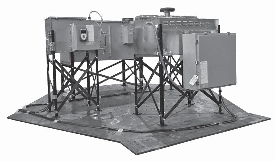
4 STEAM-TO-STEAM STS-25 through STS-100 fl oor mount installation drawing Refer to the STS IOM for all other installation, operation, and maintenance instructions. Complete the seismic installation as shown in Figure 2-1 and the installation steps on the next page. FIGURE 2-1: STS-25 THROUGH STS-100 FLOOR MOUNT SEISMIC CERTIFICATION OPTION INSTALLATION Crossbrace in Length mm Front/Rear, STS /8 727 Front/Rear, STS /4 793 Side, STS /8 917 Side, STS / Front 1/4" Nut (12) Detail A (Top View) 1/4" Washer (24) See Detail A 1/4" Bolt (12) 1/4" Nut (12) 1/4" Washer 1/4" Washer 1/4" Bolt See Detail B Spacer (8) 3/8" Bolt (16) 3/8" Bolt "L" 3/8" Washer (32) Spacer 3/8" Washer "R" "R" Front/rear cross braces Side cross braces "L" 3/8" Nut (4) 3/8" Minimum grade 2 bolts. Refer to Anchorage details supplied by the Structural Engineer of Record. Notes: 1. The height from floor to bottom of tank is 32 ¹/8 in (815 mm). 2. All hardware shown supplied by DriSteem. 3. All cabinet mounted keypads require captive bracket. All controllers require captive standoffs. 3/8" Nut 3/8" Washer Detail B (Top View) DM
5 STEAM-TO-STEAM STS-25 through STS-100 fl oor mount installation steps 1. Attach legs to tank assembly. See Detail A in Figure 2-1. a. Identify Front Right and Back Left leg weldments. The side of the humidifier with the drain assembly and heat exchanger connections is the front. The two leg weldments with R marked on the bottom of the feet are used in these locations. Holding the leg weldments so that the angle iron is in the shape of an L when looking at it from the top, these have the fourth hole closer to the third hole on the horizontal part of the L. Reference Figure 2-1 for proper locations. b. The other two weldments, marked L on the bottom of the feet, are used in the Front Left and Back Right locations. See Figure 2-1 for back view callout. Callout will help orientation during installation. c. Use supplied 1/4"-20 x 1/4" bolts to attach leg weldments to tank. Use all three bolt locations on all legs. d. Leave these bolts loose until after cross braces are completely assembled and tightened in step Attach cross braces to legs. See Detail B in Figure 2-1. a. Attach cross braces to legs as shown. Use three square spacers on each side of the outer cross braces to prevent bowing. b. Torque all cross brace bolts to 30 ft-lbs (40 N-m). 3. Torque all leg bolts to 8 ft-lbs (10 N-m). 4. Attach legs to support structure using all four bolt hole locations and in accordance to instructions by the Structural Engineer of Record. 5. Refer to the STS IOM for all other installation, operation, and maintenance instructions. 3
6 STEAM-TO-STEAM STS-200 through STS-800 fl oor mount installation drawing Refer to the Steam-to-Steam (STS humidifier) IOM for all other installation, operation, and maintenance instructions. Complete the seismic installation as shown in Figure 4-1 and the installation steps on the next page. FIGURE 4-1: STS-200 THROUGH STS-800 FLOOR MOUNT SEISMIC CERTIFICATION OPTION INSTALLATION Crossbrace Length in mm Front/Rear, STS /4 857 Side, STS / /8" Washer 3/8" x 3" Bolt 3/8" Washer 3/8" Nut (8) 3/8" Washer (16) See Detail A 3/8" Nut 3/8" x 3" Bolt (8) Legs 3/8" Washer (16) 3/8" Washer (16) 3/8" Nut (8) Spacer (24) See Detail B 3/8" x 3-1/2" Bolt (8) Detail A (Top View) 3/8" x 3-1/2" Bolt 3/8" Washer (16) Spacers (3) Side cross braces 3/8" Nut Legs 3/8" Washer (8) 3/8" Minimum grade 2 bolts. Refer to Anchorage details supplied by the Structural Engineer of Record. Front/rear cross braces Notes: 1. The height from floor to bottom of tank is 23 7/8 in (606 mm). 2. All hardware shown supplied by DriSteem. 3. All cabinet mounted keypads require captive bracket. All controllers require captive standoffs. Detail B (Top View) 3/8" Washer DM
7 STEAM-TO-STEAM STS-200 through STS-800 fl oor mount installation steps 1. Attach legs to tank assembly. See Detail A in Figure 4-1. a. Use supplied 3/8" x 3" bolts to attach leg weldments to tank. Use both bolt locations on all legs. b. Leave these bolts loose until after cross braces are completely assembled and tightened in step Attach cross-braces to legs. See Detail B in Figure 4-1. a. Use supplied 3/8" x 31/2" bolts to attach cross braces to legs as shown. Use three square spacers on each side of the outer cross braces to prevent bending. b. Torque all cross-brace bolts to 30 ft-lbs (40 N-m). 3. Torque all leg bolts to 30 ft-lbs (40 N-m). 4. Attach legs to support structure using all eight bolt hole locations and in accordance to instructions by the Structural Engineer of Record. 5. Refer to the STS IOM for all other installation, operation, and maintenance instructions. 5
8 XT SERIES Mounting FIGURE 6-1: XT SERIES HUMIDIFIER SEISMIC CERTIFICATION OPTION WALL MOUNT INSTALLATION Models XTS / XTP 002 through 048 Models XTP 050 through 096 A B E A B C C D D OM-7662b OM-7663b Mounting hardware to be (four) 3/8" diameter grade 2 (minimum) bolts with washers, lock washers, and nuts. Mounting hardware to be (six) 3/8" diameter grade 2 (minimum) bolts with washers, lock washers, and nuts. Note: Refer to the anchorage details supplied by the Structural Engineer of Record Table 6-1: XT Series humidifier mounting keyhole dimensions Model XTS / XTP Dimension 002, 003, , , 033, 042, *, 067*, 083*, 096* inches mm inches mm inches mm inches mm A B C D E * Model XTP only mc_051712_1227 6
9 XT SERIES Mounting FIGURE 7-1: SEISMIC CERTIFICATION RETAINING STRAP INSTALLATION Retainer strap must be securely installed for all seismic applications. Strap Typical XTS/XTP Note: Loop strap thru front and back bracket on both sides. DM
10 VAPORSTREAM Vaporstream: Floor mount installation drawing Refer to the Vaporstream IOM for all other installation, operation, and maintenance instructions. Complete the seismic installation as shown in Figure 8-1 and the installation steps on the next page. FIGURE 8-1: VAPORSTREAM FLOOR MOUNT SEISMIC CERTIFICATION OPTION INSTALLATION Crossbrace in Length mm Front/Rear, all sizes 33 1/8 841 Side, 1 heater 28 1/4 717 Side, 3 heater 29 3/4 755 Side, 6 heater Side, 9 heater 33 1/4 844 Side, 12 heater 43 7/ Front 1/4" Nut (12) 1/4" Washer 1/4" Nut See detail A 1/4" Washer 1/4" Washer (24) 1/4" Bolt (12) See detail B 1/4" Bolt Detail A (top view) Spacer (8) 3/8" Bolt 3/8" Washer 3/8" Bolt (32) Spacer "R" 3/8" Nut (16) 3/8" Washer (32) "L" "L" Side cross braces 3/8" Nut Front/rear cross braces "R" (4) 3/8" Minimum grade 2 bolts. Refer to Anchorage details supplied by the Structural Engineer of Record. 3/8" Washer Notes: 1. The two leg weldments with "R" marked on the bottom of the feet are used in these locations. Holding the leg weldments so that the angle iron is in the shape of an L when looking at it from the top, these have the fourth hole closer to the third hole on the vertical part of the L. 2. The height from floor to bottom of tank is 30 ½ in (774 mm). 3. All hardware shown supplied by DriSteem. 4. All cabinet mounted keypads require captive bracket. All controllers require captive standoffs. Detail B (top view) DM
11 VAPORSTREAM Vaporstream: Floor mount installation steps 1. Attach legs to tank assembly - See Detail A in Figure 8-1. a. Vaporstream with remote control cabinet - identify Front Right and Back Left leg weldments. Side of the tank with drain assembly and clean-out plate is front. Weldments marked "L" on the bottom of feet are used in Front Left and Back Right locations. Use 1/4"-20 x 1¼" bolts to attach leg weldments to tank. Use all three bolt locations on all legs. Leave these bolts loose until after cross braces are completely assembled and tightened (Step 2). b. Vaporstream with control cabinet factory mounted on humidifier - identify Front Right and Back Left leg weldments. Side of the tank with drain assembly and clean-out plate is considered front. See Figure 8-1 for front view callout. Callout will help orientation during installation. Remove the control cabinet from tank and support it within range of motion the flexible conduit allows. Two weldments, marked "L" on the bottom of feet, are used in Front Left and Back Right locations. Use included 1/4-20 x 1¼ bolts to attach leg weldments to tank. Use all three bolt locations on all legs. Note: Available space between control cabinet brackets and tank flange is tight. It is recommended to insert bolts and washers though the holes in leg assembly and tape them in place before assembling them to tank. Once washers and nuts are started on bolts, tape can be removed. Leave bolts loose until after cross braces are completely assembled and tightened (Step 2). 2. Attach cross-braces to legs - See Detail B in Figure 8-1. a. Use square spacers on one of each side's set of cross-braces. Vaporstream with control cabinet factory mounted on humidifier: Attach the cross-braces on the control cabinet side. Attach cross-braces to legs. Depending on tank and control cabinet size there may be slots in the control cabinet support brackets. Insert cross-braces through slots. Torque all cross brace bolts to 30 ft-lbs (40.7 N-m). Replace control cabinet onto tank. 3. Torque all leg bolts to 8 ft-lbs (10.8 N-m). 4. Attach legs to support structure using all four bolt hole locations and in accordance with instructions by the Structural Engineer of Record. 9
12 VAPORSTREAM Vaporstream: Weather cover installation drawing in this manual and to a structurally stable surface. Improper mounting of the humidifier can cause it to fall or to tip, resulting in severe personal injury Refer to the Vaporstream IOM for all other installation, operation, and maintenance instructions. Complete the seismic installation as shown in Figure FIGURE 10-1: VAPORSTREAM WEATHER COVER SEISMIC CERTIFICATION OPTION INSTALLATION Vaporstream weather cover (4) 3/8" Minimum grade 2 bolts. Refer to anchorage details supplied by the Structural Engineer of Record. DM
13 VAPORMIST Vapormist: Wall mount installation drawing Refer to the Vapormist IOM for all other installation, operation, and maintenance instructions. Complete the seismic installation as shown in Figure FIGURE 11-1: VAPORMIST SEISMIC CERTIFICATION OPTION WALL MOUNT INSTALLATION 16" (406 mm) 3" (76 mm) Mounting hardware to be (two) 3/8" DIA grade 2 minimum bolts with washers, lock washers, and nuts. Refer to the anchorage details supplied by the Structural Engineer of Record. 18.5" (470 mm) Vapormist chassis DM " (609 mm) 11
14 MINI-BANK Mini-bank: Installation drawing in an air handling unit Refer to the Steam Injection IOM for all other installation, operation, and maintenance instructions. Complete the seismic installation as shown in Figure FIGURE 12-1: MINI-BANK SEISMIC CERTIFICATION OPTION INSTALLATION IN AN AIR HANDLING UNIT A-A See inset A-A at right AHU wall Section A-A 1/4" thick angle A-A 3/8" Grade 5 bolt (TYP) 1/4" thick angle (2) 1-5/8" Square Unistrut-12 gauge 1/4" thick angle #10-32 Bolts, washers, and nuts (TYP) B See inset B-B at right Typical Mini-bank B 1/4" Self tap screws 1/4" thick angle (3) 1-5/8" Square Unistrut-12 gauge 3/8" Grade 5 bolt (TYP) AHU floor Section B-B 3/4" Strut conduit clamp (TYP) DM Note: Use Nylon style locking nuts on all UniStrut hardware connections. 12
15 MINI-BANK Mini-bank: Installation drawing in a duct Refer to the Steam Injection IOM for all other installation, operation, and maintenance instructions. Complete the seismic installation as shown in Figure FIGURE 13-1: MINI-BANK SEISMIC CERTIFICATION OPTION INSTALLATION IN A DUCT Duct width Duct 1/2" NPT (DN15) connection 1.5" (38 mm) Duct height Valve Separator (M5) tapped hole. Attach dispersion end to duct with bolts, washers, and nuts. Dispersion tubes 1/2" NPT (DN15) connection 1/2" NPT (DN15) inlet Escutcheon plates fit around tubes DM
16 ULTRA-SORB Ultra-sorb: Model LV Installation drawing in an air handling unit Refer to the Ultra-sorb Models LV and LH IOM for all other installation, operation, and maintenance instructions. Complete the seismic installation as shown in Figure FIGURE 14-1: ULTRA-SORB MODEL LV SEISMIC CERTIFICATION OPTION INSTALLATION IN AN AIR HANDLING UNIT See inset A-A at right A A AHU Roof 3/8" Grade 5 bolt (3) 1/4" Thick angle Section A-A 1-5/8" Square unistrut - 12 gauge Airflow 3/8" Grade 5 steel bolt with backup washers (both sides) 1-5/8" Square unistrut - 12 gauge 24" (610 mm) Max 1/4" Self tap screw (3) 1/4" Thick angle (3) 3/8" Grade 5 bolt (2) Center support required for all units greater than 60" (1524 mm) wide. AHU floor Section B-B Typical Ultra-sorb LV B See inset B-B at right B Notes: Use Nylon style locking nuts on all UniStrut hardware connections. Air handling unit end wall or lateral bracing shall be spaced at no great than 96" (2438 mm) o.c. DM
17 ULTRA-SORB Ultra-sorb: Model LV Installation drawing in a duct Refer to the Ultra-sorb Models LV and LH IOM for all other installation, operation, and maintenance instructions. Complete the seismic installation as shown in Figure FIGURE 15-1: ULTRA-SORB MODEL LV SEISMIC CERTIFICATION OPTION INSTALLATION IN A DUCT A matching flange or metal frame is required on the ductwork for connection to the Ultrasorb flanges. Note: Use duct sealant between sections. 1/4" Grade 5 bolt, washers, and nuts. 6" (152 mm) (max) spacing on both left and right side of Ultra-sorb. 1/4" - 20 Self drill/tap sheet metal screws. 6" (152 mm) (max) spacing on both top and bottom of Ultra-sorb. Note: To avoid damaging the header, screws and drill bits must not penetrate more than 3/4" (20 mm) into the header assembly. DM
18 ULTRA-SORB Ultra-sorb: Model LH Installation drawing in an air handling unit in this manual and to a structurally stable surface. Improper mounting of the humidifier can cause it to fall or to tip, resulting in severe personal injury Refer to the Ultra-sorb Models LV and LH IOM for all other installation, operation, and maintenance instructions. Complete the seismic installation as shown in Figure FIGURE 16-1: ULTRA-SORB MODEL LH SEISMIC CERTIFICATION OPTION INSTALLATION IN AN AIR HANDLING UNIT See inset A-A at right A A AHU Roof 3/8" Grade 5 steel bolt with backup washers (6) 3/8" Grade 5 bolt (3) Section A-A 1/4" Thick Angle 1-5/8" Square Unistrut - 12 gauge Airflow 1-5/8" Square Unistrut - 12 gauge 1/4"Self tap screw (3) 1/4" Thick angle (3) 3/8" Grade 5 bolt (2) AHU floor Section B-B Typical Ultra-sorb LH B B See inset B-B at right Notes: Use Nylon style locking nuts on all UniStrut hardware connections. Air handling unit end wall or lateral bracing shall be spaced at no great than 96" (2438 mm) o.c. DM
19 ULTRA-SORB Ultra-sorb: Model LH Installation drawing in a duct Refer to the Ultra-sorb Models LV and LH IOM for all other installation, operation, and maintenance instructions. Complete the seismic installation as shown in Figure Note: For Model LH, seismic certification is only available with horizontal airflow. stable surface. Improper mounting of the humidifier can cause it to fall or to tip, resulting in severe personal injury FIGURE 17-1: ULTRA-SORB MODEL LH SEISMIC CERTIFICATION OPTION INSTALLATION IN A DUCT A matching flange or metal frame is required on the ductwork for connection to the Ultrasorb flanges. Note: Use duct sealant between sections. 1/4" Grade 5 bolt, washers, and nuts. 6" (152 mm) (max) spacing on both left and right side of Ultra-sorb. 1/4" - 20 Self drill/tap sheet metal screws. 6" (152 mm) (max) spacing on both top and bottom of Ultra-sorb. Note: To avoid damaging the header, screws and drill bits must not penetrate more than 3/4" (20 mm) into the header assembly. DM
20 ULTRA-SORB Ultra-sorb: Model XV Installation drawing in an air handling unit in this manual and to a structurally stable surface. Improper mounting of the humidifier can cause it to fall or to tip, resulting in severe personal injury Refer to the Ultra-sorb Model XV IOM for all other installation, operation, and maintenance instructions. Complete the seismic installation as shown in Figure FIGURE 18-1: ULTRA-SORB MODEL XV SEISMIC CERTIFICATION OPTION INSTALLATION IN AN AIR HANDLING UNIT See inset A-A at right A AHU Roof Section A-A A Typical Ultra-sorb XV 3/8" Grade 5 bolt (3) 1/4" Thick angle 1-5/8" Square Unistrut - 12 gauge Airflow Use nylon style locking nuts on all Unistrut hardware connections 1/4" Self tap screw (3) 1/4" Thick angle (3) 1-5/8" Square Unistrut - 12 gauge 3/8" Grade 5 bolt (2) 3/8" Grade 5 steel bolt with backup washers (both sides) AHU floor Section B-B Retainer brackets must be securely installed for all Seismic applications. 24" (610 mm) Max Dispersion tube #8-32 SST nut Retainer brackets C Header Center support required for all units greater than 60" (1524 mm) wide. B B See inset B-B at right DM Notes: Use Nylon style locking nuts on all UniStrut hardware connections. Air handling unit end wall or lateral bracing shall be spaced at no great than 96" (2438 mm) o.c. 18
21 ULTRA-SORB Ultra-sorb: Model XV Installation drawing in a duct Refer to the Ultra-sorb Model XV IOM for all other installation, operation, and maintenance instructions. Complete the seismic installation as shown in Figure FIGURE 19-1: ULTRA-SORB MODEL XV SEISMIC CERTIFICATION OPTION INSTALLATION IN A DUCT A matching flange or metal frame is required on the ductwork for connection to the Ultra-sorb flanges. Note: Use duct sealant between sections. 1/4" Grade 5 bolt, washers, and nuts. 6" (152 mm) (max) spacing on both left and right side of Ultra-sorb. 1/4" - 20 Self drill/tap sheet metal screws. 6" (152 mm) (max) spacing on both top and bottom of Ultra-sorb. Note: To avoid damaging the header, screws and drill bits must not penetrate more than 3/4" (20 mm) into the header assembly. DM
22 ULTRA-SORB Ultra-sorb: Model MP Installation drawing in an air handling unit in this manual and to a structurally stable surface. Improper mounting of the humidifier can cause it to fall or to tip, resulting in severe personal injury Refer to the Ultra-sorb Model MP IOM for all other installation, operation, and maintenance instructions. Complete the seismic installation as shown in Figure FIGURE 20-1: ULTRA-SORB MODEL MP SEISMIC CERTIFICATION OPTION INSTALLATION IN AN AIR HANDLING UNIT AHU roof 3/8" Grade 5 bolt (3) 1/4" Thick angle 1-5/8" square Unistrut - 12 gauge 3/8" Grade 5 steel bolt with backup washers (both sides) Airflow 1-5/8" square Unistrut - 12 gauge 1/4" Self tap screw (3) 1/4" Thick angle (3) 3/8" Grade 5 bolt (2) 24" (610 mm) Max AHU floor DM Center support required for all units greater than 60" (1524 mm) wide. Typical Ultra-sorb MP Notes: Use Nylon style locking nuts on all UniStrut hardware connections. Air handling unit end wall or lateral bracing shall be spaced at no great than 96" (2438 mm) o.c. 20
23 ULTRA-SORB Ultra-sorb: Model MP Installation drawing in a duct Refer to the Ultra-sorb Model MP IOM for all other installation, operation, and maintenance instructions. Complete the seismic installation as shown in Figure FIGURE 21-1: ULTRA-SORB MODEL MP SEISMIC CERTIFICATION OPTION INSTALLATION IN A DUCT Note: Use duct sealant between sections. A matching flange or metal frame is required on the ductwork for connection to the Ultra-sorb flanges. 1/4" Grade 5 bolt, washers, and nuts. 6" (152 mm) (max) spacing on both left and right side of Ultra-sorb. 1/4" - 20 Self drill/tap sheet metal screws. 6" (152 mm) (max) spacing on both top and bottom of Ultra-sorb. Note: To avoid damaging the header, screws and drill bits must not penetrate more than 3/4" (20 mm) into the header assembly. DM
24 Expect quality from the industry leader Since 1965, DriSteem has led the industry with innovative methods for humidifying and cooling air with precise control. Our focus on ease of ownership is evident in the design of the Wetted Media System. DriSteem also leads the industry with a Two-year Limited Warranty and optional extended warranty. For more information sales@dristeem.com For the most recent product information visit our website: DRI-STEEM Corporation a subsidiary of Research Products Corporation DriSteem is an ISO 9001:2008 certified company U.S. Headquarters: Technology Drive Eden Prairie, MN or (fax) European office: Grote Hellekensstraat 54 b B-3520 Zonhoven Belgium dristeem-europe@dristeem.com Continuous product improvement is a policy of DriSteem; therefore, product features and specifications are subject to change without notice. DriSteem, STS, Ultra-sorb, Vapor-logic, Vapormist, and Vaporstream are registered trademarks of Research Products Corporation and are filed for trademark registration in Canada and the European community. Product and corporate names used in this document may be trademarks or registered trademarks. They are used for explanation only without intent to infringe Research Products Corporation TWO-YEAR LIMITED WARRANTY DRI-STEEM Corporation ( DriSteem ) warrants to the original user that its products will be free from defects in materials and workmanship for a period of two (2) years after installation or twentyseven (27) months from the date DriSteem ships such product, whichever date is the earlier. If any DriSteem product is found to be defective in material or workmanship during the applicable warranty period, DriSteem s entire liability, and the purchaser s sole and exclusive remedy, shall be the repair or replacement of the defective product, or the refund of the purchase price, at DriSteem s election. DriSteem shall not be liable for any costs or expenses, whether direct or indirect, associated with the installation, removal or reinstallation of any defective product. Excluded from the Limited Warranty are all consumable and wear and tear items such as cylinders, membranes, filters, or media replacements. These items are subject to usual wear and tear during usage. DriSteem s Limited Warranty shall not be effective or actionable unless there is compliance with all installation and operating instructions furnished by DriSteem, or if the products have been modified or altered without the written consent of DriSteem, or if such products have been subject to accident, misuse, mishandling, tampering, negligence or improper maintenance. Any warranty claim must be submitted to DriSteem in writing within the stated warranty period. Defective parts may be required to be returned to DriSteem. Excluded from the Limited Warranty are all consumable and wear and tear items such as cylinders, membranes, filters, or media replacements. These items are subject to usual wear and tear during usage. DriSteem s Limited Warranty is made in lieu of, and DriSteem disclaims all other warranties, whether express or implied, including but not limited to any IMPLIED WARRANTY OF MERCHANTABILITY, ANY IMPLIED WARRANTY OF FITNESS FOR A PARTICULAR PURPOSE, any implied warranty arising out of a course of dealing or of performance, custom or usage of trade. DriSteem SHALL NOT, UNDER ANY CIRCUMSTANCES BE LIABLE FOR ANY DIRECT, INDIRECT, INCIDENTAL, SPECIAL OR CONSEQUENTIAL DAMAGES (INCLUDING, BUT NOT LIMITED TO, LOSS OF PROFITS, REVENUE OR BUSINESS) OR DAMAGE OR INJURY TO PERSONS OR PROPERTY IN ANY WAY RELATED TO THE MANUFACTURE OR THE USE OF ITS PRODUCTS. The exclusion applies regardless of whether such damages are sought based on breach of warranty, breach of contract, negligence, strict liability in tort, or any other legal theory, even if DriSteem has notice of the possibility of such damages. By purchasing DriSteem s products, the purchaser agrees to the terms and conditions of this Limited Warranty. EXTENDED WARRANTY The original user may extend the term of the DriSteem Limited Warranty for a limited number of months past the initial applicable warranty period and term provided in the first paragraph of this Limited Warranty. All the terms and conditions of the Limited Warranty during the initial applicable warranty period and term shall apply during any extended term. An extended warranty term of an additional twelve (12) months or twenty four (24) months of coverage may be purchased. The extended warranty term may be purchased until eighteen (18) months after the product is shipped, after which time no extended warranties are available. When a Dristeem humidifier is purchased with a DriSteem RO system, an extended twenty-four (24) month coverage is included. Any extension of the Limited Warranty under this program must be in writing, signed by DriSteem, and paid for in full by the purchaser. Form No. SEISMIC-IOM-EN-0118 Part No Rev D
READ AND SAVE THESE INSTRUCTIONS DRANE-KOOLER. Water Tempering Device. Installation, Operation, and Maintenance Manual
 READ AND SAVE THESE INSTRUCTIONS DRANE-KOOLER Water Tempering Device Installation, Operation, and Maintenance Manual Table of Contents Overview Features Summary...................................... 1
GTS. User Manual. Gas-to-Steam Humidifier. Affix product label here.
 Following installation of this steam-generating humidifier, the installer shall instruct the user in the operation of the steam-generating humidifier and the safety devices. The installer shall give at
Read and save these instructions! DRANE-KOOLER. Water tempering device Installation, operation and maintenance manual
 Read and save these instructions! DRANE-KOOLER Water tempering device Installation, operation and maintenance manual PLEASE: read this manual! This manual will guide you through installation, operation
VT Series. Service Kit Manual CAUTION
 VT Series Electric Humidifier Service Kit Manual WARNING Indicates a hazardous situation that could result in death or serious injury if instructions are not followed. CAUTION Indicates a hazardous situation
Vapor-logic 3 to Vapor-logic4
 Vapor-logic 3 to Vapor-logic4 Adaptor Board Installation Manual Warnings and c autions Warnings and cautions WARNING Indicates a hazardous situation that could result in death or serious injury if instructions
VAPORSTREAM. Electric-to-Steam Humidifier. With Vapor-logic controller Web-enabled access I nteroperability via Modbus or optional BACnet or LonTalk
 VAPORSTREAM Electric-to-Steam Humidifier With Vapor-logic controller Web-enabled access I nteroperability via Modbus or optional BACnet or LonTalk High-performance humidification dristeem offers a complete
READ AND SAVE THESE INSTRUCTIONS DE-SCALING SOLUTION. Humidifier De-scaling Solution and Neutralizer. Usage Instructions
 READ AND SAVE THESE INSTRUCTIONS DE-SCALING SOLUTION Humidifier De-scaling Solution and Neutralizer Usage Instructions Safety instructions HUMIDIFIER DE-SCALING SOLUTION HUMIDIFIER DE-SCALING NEUTRALIZER
XT SERIES. Electrode Steam Humidifiers. Easy to maintain Adaptable Comprehensive control with Vapor-logic option
 XT SERIES Electrode Steam Humidifiers Easy to maintain Adaptable Comprehensive control with Vapor-logic option Cost-effective steam humidification XT Series electrode steam humidifiers from DriSteem provide
XT SERIES. Electrode Steam Humidifiers. Easy to maintain Adaptable Comprehensive control with Vapor-logic option
 XT SERIES Electrode Steam Humidifiers Easy to maintain Adaptable Comprehensive control with Vapor-logic option Cost-effective steam humidification Model XTP XT Series electrode steam humidifiers from DriSteem
XTR. Electrode Steam Humidifier
 XTR Electrode Steam Humidifier Easy to operate E asy to maintain just replace the cylinder Affordable to buy, economical to operate D isperse steam into ductwork or open spaces Humidify for health and
Ultra-sorb Models LV and LH
 Ultra-sorb Models LV and LH Steam Dispersion Panels Installation, Operation, and Maintenance Manual For applications using steam from a boiler or from any DRI-STEEM steam generating humidifier. Overview
MaxLite LED MICRO-T PANEL
 ` Installation Instructions General Safety Information To reduce the risk of death, personal injury or property damage from fire, electric shock, falling parts, cuts/abrasions, and other hazards read all
Armstrong ExpressPack Multi-Tube Steam Dispersion Panel Assembly and Installation Instructions
 Armstrong ExpressPack Multi-Tube Steam Dispersion Panel Assembly and Installation Instructions IOM-573 This bulletin should be used by experienced personnel as a guide to the installation and maintenance
Humidifi er FAQ. Why is the humidifier not running? The following conditions need to be satisfied before the humidifier sequence can start:
 Humidifi er FAQ UNIT OPERATION AND TROUBLESHOOTING Why is the humidifier not running? The following conditions need to be satisfied before the humidifier sequence can start: Must be in Auto mode No flashing
THE SIX STEPS OF HUMIDIFICATION DESIGN
 THE SIX STEPS OF HUMIDIFICATION DESIGN To help you better understand the humidification process, this issue of Engineering Humidification will walk you through the basic steps of humidification system
MaxLite LED VAPOR TIGHT LINEAR FIXTURES
 A cost effective LED Vapor Tight Fixture features a full length polycarbonate lens and a one-piece white glass reinforced polyester (GRP) body. Designed to meet or exceed seven to 10 foot-candles at 8
HIGH-PRESSURE ATOMIZING SYSTEM. Humidification and adiabatic cooling. Energy efficient Reduces cooling load Multiple zone capabilities
 HIGH-PRESSURE ATOMIZING SYSTEM Humidification and adiabatic cooling Energy efficient Reduces cooling load Multiple zone capabilities Preliminary 02071 Advanced, efficient humidification PURE PRESSURIZED
Steam Injection Humidifiers for use with steam boilers PRODUCT CATALOG
 Steam Injection Humidifiers for use with steam boilers PRODUCT CATALOG Suitable for a wide range of applications Steam Injection humidifiers from DRI-STEEM use steam from an external source, such as an
ALL PRODUCTS BROCHURE
 Who we are EPERTS We design and manufacture humidification systems to meet your unique humidification requirements. We have earned our reputation as the humidification experts by supporting customers unique
Humidifier De-scaling Solution. and Neutralizer. Usage Instructions. IMPORTANT: Read and save these instructions. Before
 IMPORTANT: Read and save these instructions. Humidifier De-scaling Solution and Neutralizer Usage Instructions Before Humidifier De-scaling Solution After Humidifier De-scaling Solution S a f e t y i n
EVAPORATIVE COOLING AND HUMIDIFICATION. High-Pressure System Wetted Media System
 EVAPORATIVE COOLING AND HUMIDIFICATION High-Pressure System Wetted Media System Energy efficient Provides both direct and indirect evaporative cooling Multiple zone capabilities in air handlers, ducts,
VAPORSTREAM. Electric-to-Steam Humidifier. With Vapor-logic controller Web-enabled access Interoperability via Modbus or optional BACnet or LonTalk
 VAPORSTREAM Electric-to-Steam Humidifier With Vapor-logic controller Web-enabled access Interoperability via Modbus or optional BACnet or LonTalk High-performance humidification APPLICATION VERSATILITY
Steam Injection Humidifiers for use with steam boilers PR0DUCT CATALOG
 Steam Injection Humidifiers for use with steam boilers PR0DUCT CATALOG Suitable for a wide range of applications Steam Injection humidifiers from DRI-STEEM use steam from an external source, such as an
INSTRUCTION MANUAL HS-229G
 INSTRUCTION MANUAL HS-229G 510977 STEP 1 - Where to Install the Thermostatic Steam Trap Determine where to install the thermostatic steam trap based on the following information. a. The trap should be
SPA BLOWER OWNER'S MANUAL XXXX, XXXX, XXXX, XXXX, XXXX, XXXX fax
 SPA BLOWER OWNER'S MANUAL 80015-XXXX, 80016-XXXX, 80017-XXXX, 80018-XXXX, 80019-XXXX, 80020-XXXX fax 888.610.3839 2015 323300-015 6/15 THIS PAGE INTENTIONALLY LEFT BLANK. 2 Operating Instructions and Parts
STS Steam-to-Steam Humidifier
 IMPORTANT: Read and save these instructions. STS Steam-to-Steam Humidifier Installation, Operation, and Maintenance Manual Warnings and cautions WARNING Indicates a hazardous situation that could result
ALL PRODUCTS BROCHURE
 ALL PRODUCTS BROCHURE Who we are EXPERTS DriSteem is a premier provider of humidification and evaporative cooling systems. We engineer our products to meet specific demands and custom requirements. We
MaxLite LED High Bay Fixtures
 General Safety Information To reduce the risk of death, personal injury or property damage from fire, electric shock, falling parts, cuts/abrasions, and other hazards read all warnings and instructions
FLCH4R Garage and Utility Electric Heater
 FLCH4R Garage and Utility Electric Heater Installation, Operation & Maintenance Instructions Model No. Volts Amps Watts BTU/HR Phase High Low High Low High Low Min Fuse Size* FLCH4R 208 17.3 8.66 3600
Installation Manual Universal Single-Arm Side-of-Pole Mount UNI-SA/21.5
 Installation Manual Universal Single-Arm Side-of-Pole Mount UNI-SA/21.5 Solar Mounting Solutions UNI-SA/21.5 March 2009 www.ironridge.com 2009 IronRidge, Inc. All Rights Reserved Version 2.0 2 Universal
DRI-STEEM CRU SERIES ELECTRIC STEAM HUMIDIFIERS
 READ AND SAVE THESE INSTRUCTIONS DRI-STEEM CRU SERIES ELECTRIC STEAM HUMIDIFIERS Installation Instructions and Maintenance Operations Manual For Toll-Free Customer Support, Call: 1-800-328-4447 UL RECOGNIZED
INSTRUCTIONS PARTS LIST For President, Monark, Standard, and Fast-Flo Pumps, and Agitator
 INSTRUCTIONS PARTS LIST 308 466 KEEP FOR REFERENCE STAINLESS STEEL, PASSIVATED Drum Covers Part No. 37 306 Drum Cover, Series A For President, Monark, Standard, and Fast-Flo Pumps, and 06 758 Agitator
Vaporstream Electric Humidifier. Installation, Operation, and Maintenance Manual
 Vaporstream Electric Humidifier Installation, Operation, and Maintenance Manual Warnings and cautions WARNING Indicates a hazardous situation that could result in death or serious injury if instructions
Sound Cover [ , , , ]
![Sound Cover [ , , , ]](/thumbs/75/71490668.jpg "Sound Cover [ , , , ]") Sound Cover [77001603, 77001604, 77001605, 77001606] Intended Use: To provide lower sound (dba) levels for Midmark PowerAir Compressors. Requirements / Restrictions: After cover is mounted to compressor,
Sound Cover [77001603, 77001604, 77001605, 77001606] Intended Use: To provide lower sound (dba) levels for Midmark PowerAir Compressors. Requirements / Restrictions: After cover is mounted to compressor,
Heater Installation Kit
 Instructions - Parts Heater Installation Kit 30677B Part No. 248428 Includes parts needed to install VISCON HP heater onto cart. Order VISCON HP heater separately. Important Safety Instructions Read all
ALL PRODUCTS BROCHURE
 Who we are EPERTS We design and manufacture humidification systems to meet your unique humidification requirements. We have earned our reputation as the humidification experts by supporting customers unique
Compact Equipment Warranty Policy
 006 07.15 Compact Equipment Warranty Policy 07/2015 Table of Contents Preface Page 1 Distributor s Warranty Responsibilities Page 1 Standard Warranties Page 2 Warranty Coverage Page 2 Warranty Limitations
Flat Line Spray Systems Kits
 Instructions/Parts Flat Line Spray Systems Kits 3A03B EN Heated or non-heated fluid circulation kits for Merkur, Merkur Bellows, and NXT Dura-Flo Pumps. For professional use only. Maximum Fluid Working
Clean Steam Generators
 Clean Steam Generators Steam for Humidification Steam for Autoclaves Clean steam using existing steam as an energy supply Introducing the CX System for clean steam generation in large facilities. It's
Ultra-sorb Steam Dispersion Tube Humidifier Panel
 Ultra-sorb Steam Dispersion Tube Humidifier Panel Installation, Operation, and Maintenance Manual For applications using steam from a boiler or from any DRI-STEEM steam generating humidifier. Table of
G Series SAVE THESE INSTRUCTIONS. (Model B) Convector Heater for Hazardous Locations GENERAL! INSTALLATION
 Convector Heater for Hazardous Locations GENERAL! INSTALLATION") G Series (Model B) Convector Heater for Hazardous Locations Type G-Series Convection Heaters are designed for use in Class I, Div. I hazardous environments. Units without control options are suitable for
G Series (Model B) Convector Heater for Hazardous Locations Type G-Series Convection Heaters are designed for use in Class I, Div. I hazardous environments. Units without control options are suitable for
XT Series Thermostats
 ISO 9001 Explosion-Proof & Moisture Resistant XT Series Thermostats Installation, Operation, & Maintenance Instructions XTWA Thermostat XTWL Thermostat XTB Thermostat Part No.MI133.Rev.2.00 Date of Issue:
Vapormist Electric Humidifier. Installation, Operation and Maintenance Manual
 Vapormist Electric Humidifier Installation, Operation and Maintenance Manual ATTENTION INSTALLER Read this manual before installing. Leave manual with product owner. DRI-STEEM technical support 800-328-4447
Ultra-sorb Steam Dispersion Panels
 Ultra-sorb Steam Dispersion Panels PR0DUCT CATALOG Ultra-sorb Model LH Ultra-sorb Model LV Ultra-sorb Model XV DRI-STEEM takes the lead again with Ultra-sorb, establishing the industry standard for energy
DUST FREE CARBON Whole House Air Purifier
 DUST FREE CARBON Whole House Air Purifier Installation & Operation Manual This manual covers the following model: DF CARBON 14" - #13052 GENERAL This device is designed to be installed into an existing
EVAPORATIVE COOLING AND HUMIDIFICATION. High-Pressure System Wetted Media System
 EVAPORATIVE COOLING AND HUMIDIFICATION High-Pressure System Wetted Media System Energy efficient Provides both direct and indirect evaporative cooling Multiple zone capabilities in air handlers, ducts,
ULTRA-SORB. Installation, Operation, and Maintenance Manual MODEL. Steam Dispersion Panels
 READ AND SAVE THESE INSTRUCTIONS ULTRA-SORB MODEL MP Steam Dispersion Panels Installation, Operation, and Maintenance Manual For applications using steam from a boiler or from any DriSteem steam generating
Bathroom Exhaust Fan/Fluorescent Light Combination
 Bathroom Exhaust Fan/Fluorescent Light Combination MODEL: 769RF IMPORTANT SAFETY INSTRUCTIONS WARNING: TO REDUCE THE RISK OF FIRE. ELECTRIC SHOCK, OR INJURY TO PERSONS, OBSERVE THE FOLLOWING: A. Use this
DBF 4XL Dryer Booster Fans
 Installation and Operation Manual Item #: 401315 Rev Date: 050814 DBF 4XL Dryer Booster Fans DBF4XL Kit Includes: Dryer Booster Fan, 1 pc Fan Mounting Bracket and Hardware, 1 pc Wall Label (Mount on wasll
55-Gallon Dispenser Package
 INSTRUCTIONS-PARTS LIST INSTRUCTIONS This manual contains important warnings and information. READ AND KEEP FOR REFERENCE. 308 666 Rev. A Husky 715 55-Gallon Dispenser Package 100 psi (6.9 bar) Maximum
WARNING. Pro Pack Portable Spray Pack 3A1292C. Operation. Model 24F893 Maximum Working Pressure 12 psi (0.83 bar, MPa)
") Operation Pro Pack Portable Spray Pack - For use with Graco hand-held sprayers (except Fine-Finish sprayers) - - For portable spray applications of water-based and oil-based (mineral spirit-type) architectural
Operation Pro Pack Portable Spray Pack - For use with Graco hand-held sprayers (except Fine-Finish sprayers) - - For portable spray applications of water-based and oil-based (mineral spirit-type) architectural
Installation & Operation Manual
 Humidity & Temperature Sensor 086 Accessories 086_D 08/12 Replaces: New Installation & Operation Manual Introduction The Humidity & Temperature Sensor 086 can be connected to select tekmar thermostats
Manual Addendum For Dyna-Fog Hurricane ES
 Manual Addendum For Dyna-Fog Hurricane ES TM The following pages attached in this addendum should be used instead of the manual when referring to components on your Hurricane ES. Warranty Limited Warranty
Installation Manual Universal Top-of-Pole Mount UNI-TP/08LL
 Installation Manual Universal Top-of-Pole Mount UNI-TP/08LL Solar Mounting Solutions UNI-TP/08LL April 2010 www.ironridge.com 2010 IronRidge, Inc. All Rights Reserved Version 2.0 2 Universal Top-of-Pole
OPERATION, SERVICE & PARTS MANUAL
 OPERATION, SERVICE & PARTS MANUAL BROASTER 620NXP & 621 EASY BREADER Be sure ALL installers read, understand, and have access to this manual at all times. MODEL 620NXP MODEL 621 Genuine Broaster Chicken,
VAPORSTREAM Models VLC and VLDI
 READ AND SAVE THESE INSTRUCTIONS VAPORSTREAM Models VLC and VLDI ELECTRIC STEAM HUMIDIFIERS Installation Instructions and Maintenance Operations Manual For Toll-Free Customer Support, Call 1-800-328-4447
Wrap-Around TOTE Tank / IBC Heaters (TOTE and TOT Series)
") Wrap-Around TOTE Tank / IBC Heaters (TOTE and TOT Series) Instruction Manual Read and understand this material before operating or servicing these heating tapes. Failure to understand how to safely operate
Wrap-Around TOTE Tank / IBC Heaters (TOTE and TOT Series) Instruction Manual Read and understand this material before operating or servicing these heating tapes. Failure to understand how to safely operate
Model: EF34. Owner's Guide & Installation Manual
 Owner's Guide & Installation Manual WARNING: Read this manual before using this product. Failure to follow the instructions and safety precautions in this manual can result in damage to property, serious
Installation and Operation Manual
 Model 8120X Digital Ventilation Controller CODE MIN/ HR Installation and Operation Manual TABLE OF CONTENTS WARNINGS AND CAUTIONS Warnings and Cautions... 3 Package Contents... 4 Specifications.... 4 Mounting
Please Read and Save These Instructions.
 Page 1 of 8 RadonAway Ward Hill, MA. GP500 Fan Installation Instructions Please Read and Save These Instructions. DO NOT CONNECT POWER SUPPLY UNTIL FAN IS COMPLETELY INSTALLED. MAKE SURE ELECTRICAL SERVICE
MN908 No. 282C Replaces 282B LB7013
 No. 282C Replaces 282B LB7013 Instruction Manual For Baldor Dust Control Units Models DC7, DC7 3, DC8, DC8 3, DC10, DC10 3, DC12, DC12 3 and DC14 3. For use on Grinders mounted to GA16 and GA20 pedestals
COMPRESSED AIR DRYER. SAFETY... Page 2 MAINTENANCE... Page 5. INSTALLATION... Page 3 PARTS AND KITS... Page 6
 OWNERS MANUAL BOSS COMPRESSED AIR DRYER Distributed by Air & Vacuum Process, Inc. Phone: 281-866-9700 Fax: 281-866-9717 Email: sales@airvacuumprocess.com SAFETY... Page 2 MAINTENANCE... Page 5 INSTALLATION...
Duct Mount. Installation Instructions
 Duct Mount Installation Instructions 00809-0600-4975 Legal Notice The Flame Detector described in this document is the property of Rosemount. No part of the hardware, software, or documentation may be
36 & 48 E-Z Cone Fan. Installation & Operator s Instruction Manual (Direct Drive)
") 36 & 48 E-Z Cone Fan Installation & Operator s Instruction Manual (Direct Drive) September 1997 MV1433C Chore-Time Warranty Chore-Time Equipment warrants each new product manufactured by it to be free
36 & 48 E-Z Cone Fan Installation & Operator s Instruction Manual (Direct Drive) September 1997 MV1433C Chore-Time Warranty Chore-Time Equipment warrants each new product manufactured by it to be free
Model CV-1FR Riser Check Valves 2 to 12 Inch (DN50 to DN300) General Description. Installation. Technical Data. Page 1 of 6 OCTOBER 2010 TFP950
 General Description. Installation. Technical Data. Page 1 of 6 OCTOBER 2010 TFP950") Technical Services 00--9 +-0--0 www.tyco-fire.com Model CV-FR Riser Check Valves to Inch (DN0 to DN00) General Description The TYCO Model CV-FR Riser Check Valve is a compact and rugged swingtype unit
Technical Services 00--9 +-0--0 www.tyco-fire.com Model CV-FR Riser Check Valves to Inch (DN0 to DN00) General Description The TYCO Model CV-FR Riser Check Valve is a compact and rugged swingtype unit
OPERATION, SERVICE & PARTS MANUAL
 OPERATION, SERVICE & PARTS MANUAL BROASTER 620N & 621 EASY BREADER Be sure ALL installers read, understand, and have access to this manual at all times. MODEL 620N MODEL 621 Genuine Broaster Chicken, Broasted,
READ AND SAVE THESE INSTRUCTIONS XT SERIES. Electrode Steam Humidifiers. Installation, Operation, and Maintenance Manual
 READ AND SAVE THESE INSTRUCTIONS XT SERIES Electrode Steam Humidifiers Installation, Operation, and Maintenance Manual Warnings and cautions WARNINGS AND CAUTIONS WARNING Indicates a hazardous situation
Industrial Vacuums, Inc
 Instructions/Spare Parts Manual Nilfisk Model GWD255 Drum Top Vacuum CAUTION: This Nilfisk vacuum cleaner is not to be used in explosion-hazardous areas, as serious injury could result. Under no circumstances
User s Manual and Operating Instructions
 User s Manual and Operating Instructions Model Numbers: CL-30P-DDF, CL-20F-DDF, CL-24O-DDF, CL-30-DDF READ AND SAVE THESE INSTRUCTIONS IMPORTANT: Read and understand all of the directions in this manual
Installation/Operation Instructions COMP-COOL50/COMP-COOL50P 50 CFM COMPONENT COOLERS
 Installation/Operation Instructions COMP-COOL50/COMP-COOL50P 50 CFM COMPONENT COOLERS (I)COMP-COOL50 (I)COMP-COOL50P Thank you for purchasing the (I)COMP-COOL50/(I)COMP-COOL50P Component Coolers. Please
Installation Manual Universal Side-of-Pole Mount UNI-SP/02A
 Installation Manual Universal Side-of-Pole Mount UNI-SP/02A Solar Mounting Solutions UNI-SP/02A September 2009 www.ironridge.com 2009 IronRidge, Inc. All Rights Reserved Version 2.1 2 Universal Side-of-Pole
Installation Manual Universal Top-of-Pole Mount UNI-TP/02
 Installation Manual Universal Top-of-Pole Mount UNI-TP/02 Solar Mounting Solutions UNI-TP/02 April 2008 www.ironridge.com 2008 IronRidge, Inc. All Rights Reserved Version 1.0 2 Universal Top-of-Pole Mount
CVS Model Inline Multi-Port Ventilators
 Installation Manual Item #: 402332 Rev Date: 081613 CVS Model Inline Multi-Port Ventilators United States 10048 Industrial Blvd., Lenexa, KS, 66215 Tel.: 800.747.1762 Fax: 800.487.9915 Canada 50 Kanalflakt
e Bath Fan with Light User s Guide
 e Bath Fan with Light User s Guide abfl50uq, BFL60UQ, BFL70, BFL85 Item Stock Number(s): BFL50UQ, BFL60UQ, BFL70, BFL85 IMPORTANT INSTRUCTIONS - OPERATING MANUAL READ AND SAVE THESE INSTRUCTIONS READ CAREFULLY
GASGUARD LEL 3 OPERATING & INSTALLATION MANUAL
 GASGUARD LEL 3 Ammonia Sensor OPERATING & INSTALLATION MANUAL GasGuard LEL 3 Operating and Installation Manual 2 Table of Contents 3GasGuard LEL Operating and Instruction Manual General description. 4
Steam Humidifier Fan Pack Installation & Maintenance Instructions
 850 Steam Humidifier Fan Pack 5658 Fan Pack Service Part Steam Humidifier Fan Pack Installation & Maintenance Instructions TABLE OF CONTENTS Safety Cautions...2 Materials List...3 Operation...3 Specifications
SH-300, SH-900, SH-1500, SH-1600 and SH-1700 Bimetallic Steam Trap Installation and Operation Manual
 SH-300, SH-900, SH-1500, SH-1600 and SH-1700 Bimetallic Steam Trap Installation and Operation Manual 111-EN SH-300 SH-900 SH-1500 SH-1600 SH-1700 Table of Content. General Safety Information. 3 Product
Bathroom Exhaust Fan/Fluorescent Light Combination
 Bathroom Exhaust Fan/Fluorescent Light Combination MODEL: 8663RF Suitable for use in shower or tub enclosure when used with GFCI protected branch circuit. The exhaust fan consists of the housing, power
Electric Space Heater
 The Choice of Professionals Model No. FUH Series Electric Space Heater Installation & Maintenance Instructions SPECIFICATIONS: FUH 54B Heater Rating and Voltage 5000 W @ 40V 465W @ 40V 333W @ 40V 500W
BX Series. Installation, Operation, Maintenance Instructions & Spare Parts
 ISO 9001 BX Series Installation, Operation, Maintenance Instructions & Spare Parts WARNING WARNING. The BX convection heater is a heavy duty baseboard designed for use in industrial environments and is
DEDPV-705, DEDPV-705 Hi Alt Dryer Exhaust Duct Power Ventilator (DEDPV)
") Installation and Operation Manual Item #: 483443 Rev Date: 2018-04-23 DEDPV-705, DEDPV-705 Hi Alt Dryer Exhaust Duct Power Ventilator (DEDPV) DEDPV-705 Kit Includes: Inline Fan with Integral Control, 1
Installation and Operation Manual Item #: 483443 Rev Date: 2018-04-23 DEDPV-705, DEDPV-705 Hi Alt Dryer Exhaust Duct Power Ventilator (DEDPV) DEDPV-705 Kit Includes: Inline Fan with Integral Control, 1
OCH-SSE series Direct Wired Units Indoor * and Outdoor Comfort Heaters
 TPI Corporation P.O. Box 4973 Johnson City, TN 37601 www.tpicorp.com OCH-SSE series Direct Wired Units Indoor * and Outdoor Comfort Heaters *EXCLUDING RESIDENCES IMPORTANT SAFETY INFORMATION INSIDE possible
READ AND SAVE THESE INSTRUCTIONS
 READ AND SAVE THESE INSTRUCTIONS MICROPROCESSOR HUMIDIFIER CONTROL SYSTEM INSTALLATION INSTRUCTIONS and OPERATIONS MANUAL TABLE OF CONTENTS TO THE PURCHASER AND THE INSTALLER: Thank you for deciding to
Easy installation in both new construction and retrofit. ZB90C ZB110C X2 Multi-Speed Ventilation Fan INSTALLATION GUIDE
 READ AND SAVE THESE INSTRUCTIONS Installer: leave this guide with homeowner. Register your product online at www.broan.ca/register.asp. ZB90C ZB0C X Multi-Speed Ventilation Fan INSTALLATION GUIDE Easy
Operation & Installation Guide
 ENGLISH Operation & Installation Guide Office / Security Safes with Key Lock DUPLICATE KEYS ARE NOT AVAILABLE FOR THESE SAFES Models 5410, 5440, 5445, 5465 Read this manual carefully and never store it
SUTTON 52 CEILING FAN
 SUTTON 52 CEILING FAN MODELS #50188, 50189, 50190 Español p. 19 Questions, problems, missing parts? Before returning to your retailer, call our customer service department at 1-877-361-3883, Monday - Thursday,
CPL Series Pedestal Convection Heater
 Installation Instructions and RENEWAL PARTS IDENTIFICATION CPL Series Pedestal Convection Heater MODEL CPLAS (H=5-1/2, D=3 ) CAT. LENGTH WATTS/ TOTAL AMPERAGE NO.* L Ft. WATTS 120V 208V 240V 277V 2125
TECHNICAL ASSISTANCE TOLL FREE TELEPHONE NUMBER TECHNICAL ASSISTANCE FAX:
 ACORN SAFETY P.O. BOX 3527 CITY OF INDUSTRY, CA 91744-0527 UNITED STATES OF AMERICA WWW.ACORNSAFETY.COM INSTALLATION, OPERATION AND MAINTENANCE INSTRUCTIONS ELECTRIC ALARM WITH LIGHT AND HORN Model: S0000-AL2-C1D1-DB1
Drain Tempering Reservoir READ & SAVE THESE INSTRUCTIONS. Installation, Operation, & Maintenance. TRION
 READ & SAVE THESE INSTRUCTIONS Installation, Operation, & Maintenance TRION www.trioniaq.com Installation, Operation, & Maintenance Manual TABLE OF CONTENTS Warranty...3 Introduction...4 Operational Characteristics...4
Design Criteria. Installation
 Model G5 Sprinkler Guards for Use with Series DS-1 Sprinklers Standard, Deep, and No Escutcheons General Description The TYCO Model G5 Sprinkler Guards are designed for use with Series DS-1 Sprinklers
AIC Series Float & Thermostatic Steam Trap Installation and Maintenance Instructions
 AIC Series Float & Thermostatic Steam Trap Installation and Maintenance Instructions 138-EN Please read and save these instructions Contents General Safety Information... 3 Product Information...3-5 Product
Installation & Maintenance Instructions
 IMPORTANT INSTRUCTIONS READ AND SAVE THESE INSTRUCTIONS Saving energy and creating healthy, comfortable environments No. II-450 Date July, 2015 DRIVE-THRU UNIT 3 AIR CURTAIN SERIES DTU03 for outdoor use
Installation and Maintenance "L" and "LS" Series
 Installation and Maintenance "L" and "LS" Series IB-43-E This bulletin should be used by experienced personnel as a guide to the installation and maintenance of "L" and "LS" Series ultra capacity float
Easy installation in both new construction and retrofit
 READ AND SAVE THESE INSTRUCTIONS Installer: leave this guide with homeowner. Register your product online at www.broan.ca/register. RB80LC RB0LC ULTRA Pro TM Ventilation Fan / Light / Night Light with
LTS Liquid-to-Steam Humidifier. Installation, Operation and Maintenance Manual
 LTS Liquid-to-Steam Humidifier Installation, Operation and Maintenance Manual Overview LTS models....3 Dimensions....4 Output capacities....6 Weights, connections and heated water properties.... 7 Installation
Ultra-sorb Model XV. Installation, Operation, and Maintenance Manual. Steam Dispersion Panel. For pressurized steam applications
 Ultra-sorb Model XV Steam Dispersion Panel Installation, Operation, and Maintenance Manual For pressurized steam applications Table of contents WARNING! Steam humidification systems have extremely hot
installation instructions Fan Tray System FTA-3/FTA-6
 installation instructions Fan Tray System FTA-3/FTA-6 (3 Fan System) (6 Fan System) THANK YOU Thank you for purchasing the Fan Tray System. Please read these instructions thoroughly before installing this
Series ELO-231B 11.2 K-factor Upright and Pendent Sprinklers. Standard Response, Standard Coverage, General Description
 Technical Services: Tel: (800) 381-9312 / Fax: (800) 791-5500 Customer Service/Sales: Tel: (215) 362-0700 / (800) 523-6512 Fax: (215) 362-5385 Series ELO-231B 11.2 K-factor Upright and Pendent Sprinklers
User's Manual. and Warranty Information. ThyssenKrupp. ThyssenKrupp Access
 LIMITED WARRANTY Limited Warranty: Subject to the limitations set forth below, THYSSENKRUPP ACCESS, 4001 East 138th Street, Grandview, Missouri 64030, warrants to the ORIGINAL PURCHASER ONLY that the Volant
XT Series Electrode Steam Humidifier. Installation, Operation, and Maintenance Manual
 XT Series Electrode Steam Humidifier Installation, Operation, and Maintenance Manual ATTENTION INSTALLER Read this manual before installing humidifier. Leave manual with product owner. DRI-STEEM technical