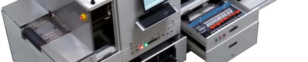
Figure 1-1 SMD-615 Furnace Front
|
|
|
- Rachel Powell
- 5 years ago
- Views:
Transcription
1 FURNACE EQUIPMENT Description of the SMD-615 infrared furnace basic thermal process elements, standard and optional hardware and their functions. Refer to section 1.6 for optional equipment description and operation. 1.1 Furnace Description The SMD-615 is a computer controlled near-infrared, conveyor belt furnace for laboratory and production thermal processing in the range of ⁰C in a controlled atmosphere, free of outside contamination. Your furnace is configured for a maximum 600 ⁰C temperature operation. Process gas may be clean dry compressed air (CDA), nitrogen (N 2), Forming Gas (FG) and/or another inert gas. Tri-gas and dual gas furnaces may use CDA with N 2 in the furnace process zones; or N 2 and a second gas such as FG (pre-mixed N 2/H 2) or another type non-combustible gas reducing gas injected into the heating chamber. Figure 1-1 SMD-615 Furnace Front The SMD-615 furnace transports product on a 460 mm (18-inch) wide belt. In the standard design the chamber clearance above the belt is 50 mm (2 inches). Optionally the furnace can be ordered with 25 mm (1- inch) or 100 mm (4-inch) vertical clearance above belt. SMD-615 furnaces feature a hermetically sealed heating chamber permitting control of the furnace chamber process environment. Baffle sections before and after the heating section contain curtains that hang down to just above the belt to further isolate the furnace chamber from the room atmosphere and from the cooling section. The SMD-615 can process surface mount devices, substrates, wafers, PCBs, metal, ceramic, glass or polycarbonate parts for electronic package sealing, thermo-setting polymer curing, reflow soldering, copper and hybrid/thick film firing, brazing, brazing, tempering and metal sintering applications, or almost any kind of general thermal processing requiring precision temperature control in a controlled atmosphere environment. The SMD-615 can also be used for precise curing of coatings on optical lenses, advanced thin film crystalline silicon, cadmium telluride (CdTe alloys) and certain copper indium diselenide (CIS-alloys) as well as many other production applications


2 Section Furnace Views Figure 1-2 SMD-615 Furnace Front Elevation Figure 1-3 Entrance Elevation Figure 1-4 Exit Elevation 1-2 SMD-615 Owner s Manual


3 Equipment Description Figure 1-5 Front, Panels Off Figure 1-6 Rear, Panels Off

4 Section Furnace Elements Furnace Arrangement During furnace operation, parts are carried from the load station through the heating and cooling sections of the furnace to the unload station on a 380 mm (15-inch) wide belt driven by an adjustable speed motor. Maximum vertical parts clearance inside the standard furnace is 50 mm (2 inches). Figure 1-7 Process Sections Process atmosphere is controlled much like a clean room: pressurized gas is pushed through the heating chamber insulated walls providing pre-heated, laminar flow for a uniform, stable atmosphere. Zones. The heating chamber is divided into zones separated by insulating dividers so that adjacent zones can maintain different setpoint temperatures, if required. Control starts with K-type thermocouples in each zone quickly sensing changing conditions and feeding these signals to the PLC which communicates with the furnace computer. The furnace software PID loop algorithms control arrays of IR quartz heating lamps inside the heating chamber so as to maintain the desired temperature setpoint in each zone. Product cooling is by radiant cooling and CDA or N2 gas convective cooling in an enclosed tunnel, with exterior fan heat removal. Heat Transfer Methods Transfer of heat in the furnace is by three different methods: Radiation, Convection and Conduction. In order of their contribution to heating the product, these methods are: A. Radiation The furnace lamps emit infrared electromagnetic waves which, when striking and absorbed by product on the belt, cause its temperature to rise. Heat lamps and microwave ovens work in a similar manner and it is also the way the sun heats the Earth. The infrared radiation does not directly heat the process gas within the furnace. B. Convection During operation, lamp radiation heats the chamber top, bottom and side wall insulation. As the process gas enters the furnace through the porous ceramic insulation, it is heated to near the setpoint temperature of the zone. This flow of heated gas transfers heat to the product on the belt. Hair dryers and home forced air heating function in the same fashion. C. Conduction Lamp radiation heats the transport belt which becomes a heat source for the product supported on the belt. Electric stoves and hot plates heat in this way. Controlled Atmosphere TPS furnaces are equipped with the ability to supply constant streams of a supplied process gas. This feature allows the user to reduce product oxidation or contamination, remove process effluents or reduce other potentially negative effects of ambient air at high temperatures. 1-4 SMD-615 Owner s Manual

5 Equipment Description A controlled atmosphere also helps establish higher consistency in thermal processes. When a product travels through the process section, slight changes in the atmospheric conditions in a non-controlled atmosphere environment can affect the stability and consistency of the product temperature profile. Flowmeters, Separate Chamber Top & Bottom Each furnace chamber area with a flowmeter is plumbed with a separate flowmeter for the chamber top and bottom. Allows for separate control of process gas flow above and below the belt. Hermetically Sealed Systems For most furnace systems, the lamps ends are enclosed in plenums. Gas fed to the plenums keeps the lamps cool and prolongs the life of the lamp and improves lamp IR performance. Balancing the furnace gas inflows and outflows enables the furnace to maintain a hermetic seal. While not air-tight, a hermetic seal resists the mixing of the outside atmosphere with the furnace atmosphere by maintaining a higher pressure inside the furnace chamber. Adjust PLENUM TOP and BOTTOM flowmeters to cool lamp ends and maintain stable furnace atmosphere. Furnace Process Equipment The furnace process equipment consists of the furnace chamber including entrance baffle, furnace chamber and rapid cool transition tunnel and a fan cooled section configured for 50mm (2-inch) product height (PH2), arranged as shown in Figure 1-8. Figure 1-8 Furnace Internals Together, the individual sections function as a unit to provide a carefully controlled gas atmosphere, precise temperature profile and controlled cooling. Load Station (LOAD) Located immediately before the furnace entrance, the Load station consists of two (2) horizontal stainless steel surfaces 371 mm (14.6 inches) long x 400 mm (16 inches) wide positioned on either side of the belt. The Load station provides a convenient area for handling product and for holding profiling equipment. Furnace Chamber The furnace chamber comprises the heat processing section consisting of one long chamber divided into three major sections. In the direction of the belt travel, these sections are the Entrance Baffle, Heating Zones and Rapid Cool Transition Baffle. The furnace chamber is a welded stainless steel shell lined internally with high temperature ceramic fiber insulation. The heating chamber is divided horizontally with a remote motorized lift to allow separation of the top and bottom of the furnace chamber for inspection and maintenance when the furnace is down. A. Entrance Baffle & Exhaust Stack (BE) The 381-mm (15-inch) long entrance baffle in first section of the furnace chamber isolates the heating zones from the ambient air outside the furnace entrance. A process gas curtain with a series of hanging swinging
6 Section 1 stainless steel baffle plates serves to act as a thermal barrier as well as purge the baffle and help prevent ambient air from entering the furnace. Owner can stipulate baffle clearance of 6 mm to 40 mm (0.25 to 1.5 inches) above the belt (or eliminate entirely). Your SMD-615 was shipped with 13 mm (0.50 ) baffle clearance. Adjust gas flow to the ENTRANCE BAFFLE flowmeter to isolate Zone 1 from room atmosphere. A venturi-assisted exhaust stack, or eductor, draws furnace gases out of the furnace. Before exhausting via the stack, the process gas passes over an accessible drip tray to collect exhaust condensation and prevent it from falling into the baffle section and contaminating the product. The eductor pulls 15 times its process gas flow from the furnace. Adjust gas flow to the ENTRANCE EXHAUST flowmeter to balance the furnace gas outflow with the gas inflow. B. Heating Zones The heating zones follow the entrance baffle in a 762-mm (60-inch) long section of the furnace chamber divided into furnace zones that are hermetically sealed with plenum covers over the lamp ends. Inside this section, arrays of tungsten filament quartz heating lamp tubes located above and below the belt, generate intense near-wave (sometimes called short-wave ) infrared light with a color temperature of 2500 K (peak wave length of 1.16 µm). These lamps are very efficient heaters with very fast response times, producing up to 1500 W per lamp at full power and capable of heating the furnace chamber to a state of equilibrium within minutes. Lamp Arrangement. The lamps are arranged symmetrically above and below the belt. The top and bottom lamps may be used independently or together to configure the best possible heat transfer mode for each individual process. Table 1-1 Furnace Arrangement shows the distribution of lamps and available power in each zone. See Power and Current datasheet in Section 5 for more information of the distribution of lamps and available power in each zone. Zone Zone Length (mm) Zone Length (inches) Table 1-1 Furnace Arrangement Number of Lamps Top / Btm T/B Available Zone Power (W) 415 Vac Max. Available Zone Power (W) 415 Vac / / / / / / Power Configuration. The SMD-615 furnace is wired half power in all zones to facilitate smooth and consistent delivery of heat energy. Zones 1 through 6 are each wired with one (1) string of lamps, each string consisting of four (4) lamps in series. This arrangement has been tested and will perform well throughout the design temperature range of the furnace ( ⁰C). Lamps within the furnace are arranged as shown in Table 1-2. Table 1-2 Furnace Lamp Wiring Configuration Chamber 1 Zone Strings Top/Btm Standard Configuration Lamps per String Top/Btm Total Number of Lamps 1 1 / 1 4 / / 1 4 / / 1 4 / / 1 4 / / 1 4 / / 1 4 / SMD-615 Owner s Manual
7 Equipment Description Control Zones. The furnace heating chamber is partitioned into 6 separate temperature control zones using ceramic fiber dividers. The dividers are designed with the smallest possible opening consistent with the parts clearance specifications. This partitioning assures very high thermal isolation between zones. Although the heating profile across the belt is extremely uniform, heat losses through the furnace side walls and at the belt edge supports produce a temperature drop near the edges of the transport belt. Away from the extreme edges of the belt, overall temperature uniformity across the belt is normally better than ±3 ⁰C. Edge Heaters. The Edge heaters are resistance wire heaters that run parallel to the belt and provide a useradjustable level of heat at the chamber sides. In critical applications, especially in furnaces greater than 14 inches wide, properly adjusted edge heaters can enable greater use of the furnace width because they make possible a flatter temperature profile across the width of the furnace often improving across the belt variation to ±1 ⁰C. Use the furnace software to add edge heat power (0-100%) in small increments to improve across the belt performance. Caution: because the edge heaters are controlled with a feedforward signal, addition of large amounts of edge heat power relative to lamp power can contribute to an instable operating condition. Temperature Measurement. Inside the furnace chamber, at the top center of each zone a type K thermocouple measures the temperature in that zone and provides feedback to each respective zone PID controller to determine the amount of power necessary to maintain setpoint temperatures. However useful these thermocouples are for controlling the temperature in each zone, the actual part is exposed to three heat transfer methods. As with any furnace, the most accurate way to determine what temperature product on the belt actually sees from these three methods of heating is to profile the furnace with a thermocouple placed directly on the product surface. Chamber Process Gas. Process gas (CDA, N 2, FG or other gas) is preheated before reaching the furnace interior by allowing it to permeate through the hot porous ceramic fiber insulation. This method of gas distribution minimally affects the temperature profile and helps keep the furnace interior clean. Adjust flowmeters for ZONE 1 through 6 to establish stable furnace operation and desired controlled processing atmosphere. C. Rapid Cool Transition Baffle (RCT) The Transition Baffle is similar to the entrance baffle and consists of a 381-mm (15-inch) long transition tunnel with swinging baffle plates that separate the furnace heating section from the cooling sections. It is housed in a welded stainless steel shell lined with ceramic fiber insulation. An N 2 gas curtain with a series of hanging stainless steel baffle plates serves to act as a thermal barrier as well as purge the baffle and help prevent ambient air from entering the furnace. Owner can stipulate baffle clearance of 6 mm to 40 mm (0.25 to 1.5 inches) above the belt (or eliminate entirely). Your SMD-615 was shipped with 13 mm (0.50 ) baffle clearance. Adjust EXIT BAFFLE flowmeter to control product initial temperature drop and to isolate the furnace atmosphere from the cooling section. Two venturi-assisted exhaust stacks, or eductors draw furnace gases out of the furnace. Before exhausting via each stack, the process gas passes over an accessible drip tray to collect exhaust condensation and prevent it from falling into the baffle section and contaminating the product. Each eductor pulls 15 times its process gas flow from the furnace. Adjust gas flow to the EXIT EXHAUST 1 and EXIT EXHAUST 2 flowmeters to rapidly evacuate heat and process atmosphere from the furnace as well as balance the furnace gas outflow with the gas inflow


8 Section 1 Water Cooled Section (CAWC) option not included The Closed Atmosphere Water Cooled section is an enclosed section with process gas air rakes for rapid cooling. Air rakes are mounted above the belt to improve transfer of heat to the water inside of the cooling jackets above and below the belt. This heat must then be extracted by an external chiller. Water or other liquid coolant should be circulating through the CAWC jacket before the furnace is started. Adjust coolant flow rates at water flowmeters. Adjust process gas flow rate by adjusting flowmeters for cooling 1 and cooling 2. Clockwise adjustment decreases gas flow to the air rakes, counterclockwise increases gas flow speed (Figure 1-9). Figure 1-9 Water Flowmeters Open Belt Section Following the rapid cool transition is a short section of open belt before the fan cooled section to isolate the furnace chamber from eddy flow generated in the fan cooled section. Fan-Cooled Section (FC) Figure 1-10 Open Belt Figure 1-11 Fan-cooled Section 1-8 SMD-615 Owner s Manual
9 Equipment Description The fan cooling section is an open section with upper fan arrays Figure 1-12 Cooling Controls to cool product before exiting the furnace. Fans mounted in enclosures above the belt transfer heat to the air inside of the furnace cabinet. This cabinet air is then exhausted by cabinet fans through openings in the furnace top cover into the room or for removal by facility exhaust ducting. Adjust fan air flow rate by releasing the brake on the 10-turn knobs at the Control Console. Clockwise adjustment increases fan speed, counterclockwise decreases fan speed (Figure 1-12 Cooling Controls). Unload Station (UNLOAD) Located immediately after the final cooling stage exit, the Unload station consists of two (2) horizontal stainless steel surfaces 371 mm (14.6 inches) long x 400 mm (16 inches) wide positioned on either side of the belt. The Unload station provides a convenient area for handling and removing product exiting the furnace
 before the furnace is started to assure consistent clean dry process gas is supplied during furnace operation.")

10 Section 1 Atmosphere Supply Gas CDA, Nitrogen & Forming Gas Plant supply process gas must be filtered and regulated to bar ( psi) before the furnace is started to assure consistent clean dry process gas is supplied during furnace operation. An internal gas reservoir with check valve further regulates gas pressure to 15 psi for the belt tensioner. If the furnace supply gas pressure drops below the set point during operation, the operator should put the furnace into Cool Down. The operator can reset the system to Warm Up when air pressure is again over 70 psig. Location Table 1-3 Gas Supply Pressure Default Setting Plant Process Gas Regulator supply to furnace psig bar Furnace Regulators (CDA, N2, FG) 70- psig 4.8 bar Low Gas Pressure Alarm Switches psig bar WARNING: The flowmeters on these furnaces are rated at 70 psi (5 bar) maximum. Operating above 70 psi exposes the operator to possible injury, may cause damage to the furnace internals and insulation and voids the furnace warranty. See Section 3 for information calibration and service of the pressurized gas (N 2/CDA) system SMD-615 Owner s Manual
 The furnace control system uses a high quality industrial computer to manage user interface with the furnace controller and to store recipes.")

11 Equipment Description 1.4 Control System This control system is comprised of a programmable logic controller (PLC) and computer interface (HMI). Computer Interface (HMI) The furnace control system uses a high quality industrial computer to manage user interface with the furnace controller and to store recipes. The furnace computer can also be used for profiling and other tasks. The furnace computer is located in the 1 st bottom drawer under the Control Console PLC Figure 1-13 Furnace Computer The furnace controller is a programmable logic controller consisting of a SNAP-PAC controller connected to a SNAP PAC- EB2 Brain and analog and digital analog input and output modules mounted on a rack. The controller operates the furnace and connects via Ethernet to the furnace computer to receive instructions and to send information regarding the furnace operations and status. The PLC controller is located in the 2 nd bottom drawer from entrance, next to the furnace computer (Figure 1-15Figure 1-15). Figure 1-14 PLC Rack


12 Section 1 Figure 1-15 PLC Drawer Controller The SNAP PAC S1 programmable automation controller provides powerful, real-time control and communication to meet the furnace industrial control, monitoring, and data acquisition needs. The SNAP- PAC-S2 is a compact, industrially hardened controller that can handle multiple control, automation, and data acquisition tasks involving digital and analog control, serial string handling, PID, and enterprise connectivity. Connecting to Opto 22 serial and Ethernet-based I/O systems, the SNAP PAC S1 controller runs the furnace control programs written in Opto 22 s PAC Control software to monitor and control all critical furnace functions. The furnace controller continues to manage all aspects of furnace operation even if communication with the furnace computer is lost. Figure 1-16 PAC-S1 Controller I/O (Input / Output) The SNAP-PAC-EB2 brain is an I/O and communications processor for the furnace control system. The SNAP-PAC-EB2 provides local intelligence that frees the PAC-S1 controller for supervisory tasks. As an I/O processor, the SNAP PAC EB2 brain independently handles functions such as latching, thermocouple linearization, watchdog timers, and PID loop control. These functions continue to work in the brain even if communication with the SNAP PAC controller is lost. Figure 1-17 PAC-EB2 I/O Brain 1-12 SMD-615 Owner s Manual
13 Equipment Description Ethernet Switch The furnace computer, SNAP PAC S1 controller and SNAP PAC brains and I/O communicate over standard 10/100 Mbps Ethernet networks and can be attached to existing wired or wireless Ethernet networks. The system includes an industrial Ethernet switch which provides connection to local intelligence and to digital and analog sensors and actuators as well as serial devices. Figure 1-18 Ethernet Switch (R) and Controller (L) Each of the devices and independent Ethernet ports have separate IP addresses. See Figure 1-19Figure 1-19 Furnace network for typical furnace network configuration


14 Section 1 Furnace Ethernet Network The furnace network consists of the furnace computer, a SNAP PAC S1 controller and one or more SNAP PAC brains and I/O racks which communicate over standard 10/100 Mbps Ethernet networks and can be attached to existing wired or wireless Ethernet networks. A typical furnace network map is shown in Figure Figure 1-19 Furnace network 1-14 SMD-615 Owner s Manual
 10-inch diameter vent grills cut into the top of the furnace cabinet, one over the furnace heating sections and one over the water cooling section.")
15 Equipment Description 1.5 Auxiliary Equipment Cabinet Exhaust Cabinet Vents. The furnace is equipped with two (2) 10-inch diameter vent grills cut into the top of the furnace cabinet, one over the furnace heating sections and one over the water cooling section. These vents exhaust heat emitted from the outside of the furnace chamber and cooling tunnel into the room or customer installed exhaust system. Cooling System Fans. The FC (forced cooling) system is cooled by fans mounted above the belt after the water cooling section. Cabinet air is forced over the belt to transfer heat from the belt and product on the belt. This air is evacuated via the cabinet fans mounted under the top of the cabinet near the furnace exit. Low Pressure Alarms (IPS) Gas Supply Pressure Switches are installed on critical process gas manifolds. These switches are normally closed. They open when proper pressure is present in the process gas supply lines. The pressure switches are factory set to open when pressure falls below the pressure set points in Table 1-4 for Gas 1 and Gas 2. Figure 1-20 Pressure Switch Table 1-4 Initial Pressure Alarm Settings Manifold Process Gas Design Pressure Pressure Set Points Gas 1 CDA 70 psi (5 bar) psi Bar Gas 2 Nitrogen 70 psi (5 bar) psi Bar Gas 3 Forming Gas or other 70 psi (5 bar) psi Bar The pressure switch set points can be adjusted manually. Locate the switch in the process gas supply line. To increase the set point turn the wheel clockwise. Turn the top of the switch counter clockwise to decrease the pressure set point so the alarm will not occur until the pressure drops to a lower point. Belt Travel (LTR) Standard direction for belt travel is from left to right when facing the furnace Control Console. As an option, the furnace can be configured for right to left operation This arrangement allows two production furnaces to be easily operated by a single person. Figure 1-21 Direction of Belt Travel
 such as this one, the conveyor belt is a close weave Nichrome-V belt manufactured from high temperature wire comprised of 80% nickel and 20% chromium.")


16 Section 1 Transport Belt The standard conveyor belt is manufactured of 316 stainless steel as installed on this furnace. For high temperature applications (>450 C) such as this one, the conveyor belt is a close weave Nichrome-V belt manufactured from high temperature wire comprised of 80% nickel and 20% chromium. These belts offer fast heat-up times, more uniform operating temperatures and excellent mechanical stability. This belt exhibits minimum shrinkage, growth, sag or distortion in use. Transport Drive Motor The transport drive motor assembly is typically mounted near the exit of the process section. Depending upon belt width, product mass, product number and belt speed, the motor-sprocket may appear different than the example shown in Figure 1-22 Transport Drive Motor. Universal Transformers All primary transformers used in the furnace are manufactured specifically for our furnaces. These transformers are 50/60 Hz multitap and can be configured to operate the furnace at most commonly available voltages worldwide. Figure 1-22 Transport Drive Motor Factory UPS Uninterruptable power supply to keep the computer, monitor and PLC controller running for at least six (6) minutes in the event the power to the furnace is disconnected or during a power outage. The UPS provides time for the operator to properly power down the furnace computer using the Windows operating system. When the furnace loses power either by: Throw open furnace circuit breaker Open EMO or interlock Loss of facility power Press Furnace Control Panel OFF The belt and all auxiliaries will stop, but the computer, monitor and PLC will continue to run. Use the Windows Shut down procedure to shut down the computer. The PLC will shut down after 6 minutes or so. Figure 1-23 Factory UPS (left) Figure 1-24 UPS, Rear View 1-16 SMD-615 Owner s Manual


 Each process gas supply line is provide with an air filter with moisture trap and pressure regulator to")
) A three phase circuit breaker is installed on the rear side of the furnace near the entrance for convenient shutoff of the furnace when not in use.")
17 1.6 Optional Equipment Equipment Description Features and operation of the most common furnace equipment options that may have been included with the furnace or added later. See Table 1-5 for a summary of featured options. Unshaded items in bold were supplied on the furnace. AFR CB-3 Air filter/trap regulator 3-phase circuit breaker Table 1-5 Summary of Advanced Features & Options GSM HO/NHM Supply gas mixing system H2 operation N2/H2 mixing CE CE mark HSK Handshake Signaling, Up/Dwn CXE CXX 200 mm Load station extension 200 mm Unload station extension LFI LT Line Interference Filter Light Tower,3-Color Process Ready OSS PH1, PH4 PPG RTL SMEMA Gas sampling system 25, 100 mm chamber height Pre-purge system, Nitrogen Right to Left Belt Travel Product alert system DGO Dual gas operation MA Moisture analyzer SSP Sample ports EM Element Monitoring system OA Oxygen Analyzer UCD Ultrasonic belt cleaner Air Filter/Trap Regulator (AFR supplied option ) Each process gas supply line is provide with an air filter with moisture trap and pressure regulator to assure supply is properly pressure is clean, dry and at a safe pressure. Circuit Breaker (CB-3 supplied option )) A three phase circuit breaker is installed on the rear side of the furnace near the entrance for convenient shutoff of the furnace when not in use. The circuit breaker is sized to prevent damage to the furnace. If the circuit breaker trips, reset by turning to ON position. If it trips again, shutdown furnace and trouble-shoot for high current draw. The CB-3 must be in OFF position to allow removal of the cover panel. Figure Phase Circuit Breaker Figure Phase Circuit Breaker-Panel OFF
 increments.")

 increments.")
18 Section 1 Load Extension (600 mm, supplied) Increases standard 400 mm (15 3/4-inch) stainless steel Load station at the entrance of the furnace in 200 mm (7-7/8-inch) increments. Useful if a longer product load area is needed. (Similar to Figure 1-27). Increases furnace length by a like amount. Unload Extension (600mm, supplied) Increases standard 400 mm (15 3/4-inch) stainless steel Load station at the exit of the furnace in 200 mm (7-7/8-inch) increments. Used for product inspection or to provide a longer period for product removal. Increases furnace length by a like amount. Figure 1-27 LA-309 Unload station with SMD-615 Owner s Manual
.")
19 Equipment Description Three Gas, Dual Mode system (DGO supplied option ) Dual mode systems can allow a specialty gas to be introduced into the furnace chamber while another gas is be provided to all furnace auxiliaries. A. DGO Equipment Includes separate manifold for supply of a different gas to the furnace heating zones (Furnace Gas2). Aux (Gas 1, CDA or nitrogen) is supplied to eductors, transition tunnels baffle sections and closed atmosphere cooling. Furnace (Gas 2) can be either the same as Gas 1, or Gas 2, forming gas or other specialty gas supplied to the furnace chambers and lamp plenums. The Control Console will sound an audible alarm and provide visual indication for a low Gas 1 or 2 supply pressure condition. B. Single Gas Operation (CDA or N2) A furnace plumbed for dual gas can be operated in single gas mode. To operate in single gas mode: To operate 1. Assure that gas is flowing from supply source at the proper supply pressure (70 psig). 2. To run furnace with compressed air in the furnace and auxiliary areas, select CDA Mode. 3. To run furnace with nitrogen in the furnace and auxiliary areas, select Nitrogen Mode. The furnace will operate with the selected gas, CDA or nitorogen flowing to all auxiliary and furnace sections. Figure 1-28 CDA - Single Gas mode Figure1-29 N2 Single Gas mode C. Dual Gas Operation (FG & N2) A furnace plumbed for dual gas is operated in much the same way as a single gas furnace. To operate in dual gas mode: 1. Assure that gas is flowing from both supply sources at the proper supply pressure (70 psig). Figure 1-30 N2/FG - Dual Gas mode 2. On the Process Screen, Select Forming Gas Mode. Forming Gas will flow to the furnace chamber and plenums. Nitrogen will flow to all auxiliary areas. The furnace will operate with nitrogen flowing to the Aux furnace sections and Gas 2, forming gas or other alternate supplied gas flowing to furnace and lamp plenums
. Normally Open and Normally Closed contacts supplied at exit of the furnace that are activated when a part is sensed at the exit (PART_AVAILABLE).")
 Three color light tower that indicates when furnace is in Process Ready, Warmup or Alarm condition.")
20 Section 1 Handshake (HSK, supplied option ) Normally Open and Normally Closed contacts supplied at entrance of the furnace that are activated when the furnace system is ready to receive a part (PROCESS_READY). Normally Open and Normally Closed contacts supplied at exit of the furnace that are activated when a part is sensed at the exit (PART_AVAILABLE). Facilitates notification to upstream and downstream equipment that the furnace is ready to process product. Light Tower (LT, supplied option ) Three color light tower that indicates when furnace is in Process Ready, Warmup or Alarm condition. Moisture Analyzer (MA option, not supplied) For processes that are sensitive to moisture, a moisture analyzer can provide status of monitored zones. The moisture analyzer can be connected to any one sample port (with SSP option) or can used with a 3-port sample system (OSS option). Figure 1-31 Light Tower A. MA Equipment The brand of moisture analyzer can generally be specified by the owner. A high quality choice, the MM510 electrolytic moisture analyzer is designed Figure 1-32 MM510 Moisture Analyzer for precise measurement of moisture in gas over a wide range (0.1 ppm to 1000 ppm with ± 5% accuracy). The analyzer is configured with an internal sample pump. The sample systems are manufactured using stainless steel throughout with 1/8-inch tube connections on the sample line. Sample flow is L/min ( cc/minute) controlled. MM510 Sensor. The phosphorus pentoxide moisture sensor consists of a dual platinum winding formed around a quartz tube about 8 cm long. A constant voltage is applied across the windings and the current monitored. The moisture in the sample gas stream causes the resistance of the platinum coil to change. The change in resistance results in a change in measured current providing an absolute measure of the moisture contained in the process sample gas. Unlike aluminum oxide sensors, the phosphorus pentoxide sensor does not require annual factory calibration. B. MA Operation The model of moisture analyzer selected will be factory set for your application. 1. Startup of the furnace will start the moisture sampling if the analyzer is left enabled by the operator. 1. A switch on the back of the analyzer allows shutoff of the analyzer while the furnace is running, if desired. 2. Sample line flow is controlled by the valve knob on the back of the analyzer Adjust to 0.15 L/min SMD-615 Owner s Manual

 and features microprocessor controlled functions, large autoranging LED display, and fast response. To avoid interference, indicate if hydrogen gas will be present.")
21 Equipment Description Oxygen Analyzer (OA, supplied option ) This furnace is equipped with an oxygen analyzer and 3- port sampling system with source gas purge. An oxygen analyzer can assure furnace settings result in a low oxygen environment in the furnace chamber during operation. The EC913 process oxygen analyzer uses an electrochemical RACE cell for accurate measurement of oxygen (measuring range: 0.1 ppm-30% at ± 2%) and features microprocessor controlled functions, large autoranging LED display, and fast response. To avoid interference, indicate if hydrogen gas will be present. The analyzer is fitted with an integral sample pump downstream of the sensor. The sample Out valve on the back of the analyzer is used for flow control and is adjustable from L/min ( cc/min) sample rate (default is 0.1 to 0.15 L/min). Figure 1-33 EC913 Oxygen analyzer On furnaces, the oxygen analyzer is usually mounted inside the furnace cabinet enclosure. The analyzer is integrated with the furnace control system. The oxygen concentration is displayed on the computer screen. Alerts and alarms are set in the process recipe on the computer. Figure 1-35 shows the O2/MA Sample system control panel on furnaces equipped with a PC computer. The oxygen concentration for the selected zone is shown on the Process screen. Figure 1-34 Oxygen analyzer next to OSS sample system During initial startup, adjust OUT valve until Sample Flow flowmeter on front of analyzer reads L/min. On subsequent startups, the flow rate does generally not need to be adjusted. Note A: When the sample line is dry, accurate readings can be obtained within minutes. If the sample line contains moisture, it may take from 20 minutes or longer. Moisture may be purged from the sample line by disconnecting the line from the analyzer and using a dry gas (nitrogen) to flush the line. Be careful to keep the pressure under 2.5 bar (35 psig) to avoid disconnecting the sample line from the furnace. Note B: When nitrogen is connected to Gas 1, Port Select S will sample the source nitrogen. Ports 1, 2 and 3 sample the respective furnace zones
. A. OSS Equipment This system consists of electrical controls and piping of a 4-port manifold to a source gas and 3 sample ports.")
 and connected to port 1 on the manifold. B. OA Operation (Process Engineer level) Start furnace and furnace software.")
22 Section 1 Sample System, Computer (OSS, supplied option ) OSS option provides user selection of any one of 3 furnace ports or the source gas (nitrogen) to a sample gas line connected to the gas analyzer equipment (typically moisture and/or oxygen analyzer). A. OSS Equipment This system consists of electrical controls and piping of a 4-port manifold to a source gas and 3 sample ports. The sample ports are located on the bottom of each furnace chamber zone. The Source is piped from Gas1 (or the nitrogen source) through a pressure regulator adjusted to 35 mbar (0.5 psig) and connected to port 1 on the manifold. B. OA Operation (Process Engineer level) Start furnace and furnace software. On the Process screen: - select O2 Port Select button to open the O2 Sampling popup, - click O2 Sampling radial button until ON is displayed to energize or de-energize system,. - Energizing O2 Sampling opens the selected port and starts analyzer and sampling pump. Figure 1-35 O2 ppmv and popup on Process screen System begins sampling the selected port. When starting system and changing ports, allow sufficient time for pump to completely purge sample. Note: When the sample line is dry, accurate readings can be obtained within minutes. If the sample line contains moisture, it may take from 20 minutes or longer. Moisture may be purged from the sample line by disconnecting the line from the analyzer and using a dry gas (nitrogen) to flush the line. Be careful to keep the pressure under 2.5 bar (35 psig) to avoid disconnecting the sample line from the furnace. C. OA Operation (Operator level) Sampling system On/Off state and selected port are stored in each recipe. To enable system: On the Recipe screen: - Get recipe with O2 Sampling and Port Select predetermined in the recipe. - O2 sampling will start when the furnace is started if the sampling system is enabled in the recipe. D. Initial Startup During initial startup, adjust analyzer OUT valve until Sample Flow flowmeter on front of analyzer reads L/min (Error! Reference source not found.). On subsequent startups, the flow rate does generally not need to be adjusted. E. Purging Sample Lines See section for using the sample system manual purge feature. F. Shut Down Sampling System On the Process Screen, click on O2 Sampling radio until OFF is displayed. Analyzer and pump shut down and sample system is isolated. Figure 1-36 Sampling Recipe popup G. Shut Down Analyzer (long term shutdown) If the analyzer is to be out of service for a period of time, further isolate the cell to prolong its life SMD-615 Owner s Manual
23 Equipment Description If system is not equipped with a check valve on the Sample OUT line, close OUT valve on back of analyzer (to isolate cell). If analyzer is disconnected from the OSS, Close IN valve on back of analyzer (to isolate cell). Note A: Analyzer valves can be left in open position while connected to the furnace as the sample port manifold will isolate the analyzer cell from gas flow when the system is off. Note B: To prolong cell life, limit sampling of air

, a board jam may considered to have occurred.")


24 Section 1 SMEMA Product Alert (option ) The SMEMA system alerts operators when product enters and exits the furnace. With the HSK handshake feature,the system provides SMEMA 1.1 Busy/Board_Available signal generation to coordinate product handling from upstream and downstream equipment. Detectors at the entrance and exit of the furnace system (Figure 1-37) will generate a BUSY or BOARD_AVAILABLE signal. If a BUSY signal at the entrance or a BOARD_AVAILABLE signal at the exit persists for more than a fixed period of time (3 seconds), a board jam may considered to have occurred. The conveyor motion will not be stopped in the event of a jam, but the machine goes into Cool-Down and an Alarm condition is displayed. A. SMEMA Equipment The SMEMA system consists of sensors located at the entrance and exit above the belt that send signals to the software when parts are detected. Each sensor is mounted on an extruded bar that allows the sensor to be placed anywhere across the belt. Figure 1-37 SMEMA Sensor Figure 1-38 SMEMA Sensor B. SMEMA Operation Easy to operate, activate the SMEMA product sensing system by clicking on the radio button below SMEMA button on the furnace software title bar to turn the system ON or OFF. Each time product passes under the entrance sensor, the Parts IN counter will increment. Each time product passes under the exit sensor, the parts OUT counter will increment. Running totals for each are shown on the title bar. C. Sensor Recipe Settings The purpose of the product sensor and onscreen tracking feature is to count the number of product units travelling through the furnace. A set of sensors at the entrance and exit detect the leading edge of a product unit leaving the loading station or arriving at the unloading station. The tracking feature sets off an alarm if the exit sensor does not detect the arrival of an expected product unit at the unloading station. The product unit length must be set in the Recipe screen (see figure 0-31) Figure 1-39 Screen showing Product Tracking settings To initiate count, activate one or more tracking lanes by clicking the lane radial buttons on the upper left corner of the process screen SMD-615 Owner s Manual
25 Equipment Description Entr Sense Delay (seconds) is the time after the sensor detects the part to it being counted IN and the Furnace_Ready signal is sent to the upstream equipment HSK contacts. Exit Transit Time is the time it takes a part to travel from the Exit sensor to the end of the belt where the next machine gets the part. The Boat_Available output signal is turned ON after the amount of time set in Exit Transit Time field as a signal to the next machine that there is a part ready to be acquired at the exit. Enter Exit Transit time in seconds. Part Length field on the Recipe screen is used to determine the time it takes for a part to pass the Exit Sensor. This time is 1.5 times the part length divided by the belt speed. This time is used to ignore false readings as the part passes by the sensor. Enter the part length in inches. D. Product Tracking Sensors The Product Tracking Sensors are self-contained fixed-field 880 nm infrared diffuse mode sensors located at the entrance and exit of the furnace. Their high excess gain and fixed-field technology allow them to detect objects of low reflectivity, while ignoring background surfaces. The cutoff distance is fixed. The most common furnace sensor model has a cutoff of 100 mm (4 inches). Backgrounds and background objects must always be placed beyond the cutoff distance. Part Number Sensor Model Output Range (cutoff) S18SN6FF25 NPN 25 mm (1 inch) S18SN6FF50 NPN 50 mm (2 inches) S18SN6FF100Q NPN 100 mm (4 inches) Table 1-6 Product Tracking Sensor Range (cutoff distance) The Sensor compares the reflections of its emitted light beam from the product unit back to the sensor s two differently aimed detectors. If the near detector light signal is stronger than the far detector light signal, the sensor responds to the object. If the far detector light signal is stronger than the near detector light signal, the sensor ignores the object. The cutoff distance is fixed (see Table 0-6). Objects lying beyond the cutoff distance usually are ignored, even if they are highly reflective. However, it is possible to falsely detect a background object under certain conditions. False sensor response will occur if a background surface reflects the sensor s light more strongly to the near detector (sensing detector) than to the far detector (cutoff detector). The result is a false ON condition. To cure this problem, angle the sensor slightly so the background does not reflect light back to the sensor. An object beyond the cutoff distance moving past the face of the sensor can cause unwanted triggering of the sensor if more light is reflected to the near detector than to the far detector. The problem is easily remedied by rotating the sensor 90. The object then reflects the two fields equally, resulting in no false triggering. Sensor Indicators. The sensor features two LED sensors (green and yellow). See table 2 for guide. Indication Green ON Steady Green Flashing Yellow ON Steady Condition Power to sensor is ON Output is overloaded Normally Open (NO) output is conducting Yellow Flashing Excess gain marginal (1 to 1.5x) in light condition Table 1-7 Product Sensor Indicating Lights Sensor Wiring. See table 0-8 and drawing for sensor hookup and wiring guide. Wire color Designation Brown +24 Vdc Blue Black White dc common Normally Open (NO) output (not used) Normally Closed (NC) output to Furnace PLC Table 1-8 Product Sensor Wiring
. Port connections are be located under chamber.")
26 Section 1 Sample Ports (SSP option ) This option includes control enclosure port connection to one or more of the sample ports located on the underside of each zone. Allows connection of an oxygen analyzer, moisture analyzer or other gas analyzer. Must be used with a sample pump (not included). Port connections are be located under chamber. Figure 1-40 shows a typical port location on a chamber. Note: The chamber is fitted so that even if this option is not included at the time of manufacture, sample ports can be added later, if required. Included with OA, MA and OSS options. Figure 1-40 Sample Port Chamber Penetration This furnace is equipped with 4 ports. Ports on zones 1, 2 and 3 are connected to the OSS sample system. The port on zone 4 is connected to a port on the front of the Oxygen analyzer drawer for easy connection of a user provided analyzer SMD-615 Owner s Manual
Figure 1-1 Furnace Front Elevation
 FURNACE EQUIPMENT 1.1 Furnace Description The LA-306 is a compact, near-infrared, conveyor belt furnace for laboratory and general purpose thermal processing in the range of 100-980 ⁰C in a controlled
Figure 1-1 Furnace Front Elevation
 FURNACE EQUIPMENT Description of the LA-306 IR furnace basic thermal process elements, standard hardware and their functions. Refer to Chapter 6 for optional equipment description and operation. 1.1 Furnace
Figure 1-1 CU-915 IR Furnace Front Elevation
 FURNACE EQUIPMENT Description of the CU-915 infrared furnace basic thermal process elements, standard and optional hardware and their functions. Refer to section 1.7 for optional equipment description
CONTINUOUS BELT IR BELT FURNACE
 CONTINUOUS BELT IR BELT FURNACE Model LA-309 Owner s Manual Revision 1 MODEL: LA- 309 SERIAL NUMBER: 13030913xx FACTORY ORDER NUMBER: 13-0xx Infrared Furnace Setup, Operation, Theory & Troubleshooting
THERMAL PROCESSING THEORY
 THERMAL PROCESSING THEORY 9.1 Infrared Waves Infrared waves form part of the electromagnetic spectrum. Electromagnetic waves with wavelengths from 0.78 µm to 1000 µm are called infrared waves. You are
CONTROLLED ATMOSPHERE INFRARED BELT FURNACE
 CONTROLLED ATMOSPHERE INFRARED BELT FURNACE Model CU-915 Owner s Manual Revision 0 MODEL: RTC CU-915 SERIAL NUMBER: 850001 FACTORY ORDER NUMBER: 16-003 Infrared Furnace Setup, Operation, Theory & Troubleshooting
DFE T ECHNOLOGY. At Conceptronic, the design and management process for reflow soldering systems is called Dynamic Flow Engineering, or DFE.
 DFE T ECHNOLOGY As components become smaller, component mixes become more diverse, and board densities continue to increase, the processes of packaging, interconnection, and assembly are challenging the
Laboratory Enclosed Scroll Air Compressor System with Premium NFPA Controls
 Laboratory Enclosed Scroll Air Compressor System with Premium NFPA Controls Specification General The Powerex Laboratory Scroll Enclosed Air Compressor System is designed to provide clean, dry air for
Conveyor and Batch Reflow Ovens
 Lead Free Soldering Technology Conveyor and Batch Reflow Ovens * LEAD FREE Conveyor Reflow Oven Features: Lead and Lead free Compatible 100% forced air Horizontal Convection TM oven** 3 vertical heating
Customers. The core of our innovation. Feeding&Conveying. Drying Dosing Temperature Control Refrigeration Granulation
 EN Customers. The core of our innovation Feeding&Conveying Drying Dosing Temperature Control Refrigeration Granulation Piovan Drying Technologies: Desiccant Bed Dryers Dried air is generated by means of
Using the DewMaster Deluxe Dew Point/ Humidity Hygrometer
 JAN 0 ::0 AM SERVOLOCK APPLICATION NOTE 0_0_ Rev Using the Deluxe Dew Point/ Humidity Hygrometer The Model is a versatile, multi-function, optical chilled mirror hygrometer designed to continuously measure
CO 2. Incubators. Incubator, the first microprocessor-based system, and the first menu-driven control system, but we offer the
 Radiant Warm Wall Compact Incubator Reduced Oxygen Incubator Automatic Water-Jacketed Incubator, stacked For more than 45 years, Lab-Line has been on the cutting edge of incubator development. Not only
SAMPLE SPECIFICATION FOR RIELLO ARRAY MODULATING BOILER
 SAMPLE SPECIFICATION FOR RIELLO ARRAY MODULATING BOILER PART 1 GENERAL 1.01 RELATED DOCUMENTS A. ANSI Z21.13 American National Standard for Gas-Fired Low Pressure Steam and Hot Water Boilers B. ASME Section
SAMPLE SPECIFICATIONS CONTINUOUS MONITORING SYSTEM (Insitu)
") PART 1 - GENERAL A. RELATED DOCUMENTS SAMPLE SPECIFICATIONS CONTINUOUS MONITORING SYSTEM (Insitu) Federal, State, and local requirements as applicable. Attached Permit Attached drawings B. SUMMARY 1. Provide
PART 1 - GENERAL A. RELATED DOCUMENTS SAMPLE SPECIFICATIONS CONTINUOUS MONITORING SYSTEM (Insitu) Federal, State, and local requirements as applicable. Attached Permit Attached drawings B. SUMMARY 1. Provide
LMV52 Control. Specifications. Document No. LV February 3, Product Description. Sample Specification
 LMV52 Control Product Description February 3, 2017 The LMV52 is a microprocessor-based burner management system with matching system components for the control and supervision of forced draft burners.
Guide Specifications
 Guide Specifications Hot Water fired Adsorption Liquid Chillers Bry-Air Adsorption Chiller Overview The chiller shall be a Bry-Air ADC series. The chiller shall consist of a robust, compact, packaged chiller
TITAN SERIES Complete Central Chiller & Pump Tank Package 20 to 70 Tons 20 F to 70 F
 Temperature Control Units Water & Oil - F Portable Chillers Air & Water-Cooled - 7 F Central Chillers Air & Water-Cooled Packages & Modules - 7 F Pump Tank Stations Chilled or Tower Water - gallons Cooling
Pioneer-R16 Gas Monitor Operator s Manual
 Pioneer-R16 Gas Monitor Operator s Manual Edition 7/2/97 RKI INSTRUMENTS, INC RKI Instruments, Inc. 33248 Central Ave, Union City, CA 94587 (510) 441-5656 Chapter 1: Description About the Pioneer-R16 Gas
CONTROLLED ATMOSPHERE IR BELT FURNACE
 CONTROLLED ATMOSPHERE IR BELT FURNACE Model LA-306 Operation & Theory Infrared Furnace Setup, Operation, Theory and Troubleshooting Guide First Edition Stephen L. Barber James M. Clark This manual contains
LED New Light Source Reflow Oven. Model: T-960
 LED New Light Source Reflow Oven Model: T-960 Features: 1. This machine selects the intelligent level sirocco and rapid infrared heating technology controlling, equipped with special design wind wheel,
F Operating Manual. ESS0460-H119 PV Module Solar Soaking Chamber
 F08-064 Operating Manual ESS0460-H119 PV Module Solar Soaking Chamber 12/19/2008 Thank you for your purchase. We are confident you will be completely satisfied with your new system. If for any reason you
THE FULL FORCED CONVECTION REFLOW SOLDERING SYSTEM SMT QUATTRO PEAK SERIES (FROM STO XLPLUS)
") THE FULL FORCED CONVECTION REFLOW SOLDERING SYSTEM SMT QUATTRO PEAK SERIES (FROM STO XLPLUS) was developed for the lead-free soldering of electronic component assemblies. The system is designed especially
THE FULL FORCED CONVECTION REFLOW SOLDERING SYSTEM SMT QUATTRO PEAK SERIES (FROM STO XLPLUS) was developed for the lead-free soldering of electronic component assemblies. The system is designed especially
Mini SMT Reflow Oven Model: T-961
 Mini SMT Reflow Oven Model: T-961 Taian Puhui Electric Technology Co., Ltd http://www.tech168.cn Http://www.tech168.cn 1/13 Features: 1. This machine selects IR and hot air heating technology controlling,
Customized Industrial Products
 Customized Industrial Products Product Catalog Large Walk-in Type Drying Oven Large Size Autoclave Large Size Fine Oven Targeting Productivity Improvement Yamato offers customization of products based
Series 3300 TELEDYNE ANALYTICAL INSTRUMENTS. The 3300 series of low cost, microprocessorbased
 TELEDYNE Series 3300 Unaffected by hydrocarbons, H2, or CO2 Easy to handle, inexpensive, and easy to replace Can apply to ppb, ppm, and percent ranges Trace & Percent Oxygen Analyzers Fuel Cell Zirconium
DF-340E PROCESS ANALYZERS APPLICATIONS FEATURES
 PROCESS ANALYZERS DF-340E The DF-340E is a Coulometric sensor based oxygen analyzer suitable for outdoor installation and designed to measure trace oxygen and percent level in pure and multigas backgrounds.
IR 3000 WBPi Online Moisture Measurement with Infrared Technology
 IR 3000 WBPi Online Moisture Measurement with Infrared Technology G Production and Quality Control with the GreCon Moisture Analyser Exploit all reserves of your production, homogenise your process, increase
PRODUCT REVIEW Honeywell HC900 Hybrid Vacuum Furnace Control System
 PRODUCT REVIEW Honeywell HC900 Hybrid Vacuum Furnace Control System Making a Difference VAC AERO Control Systems With heat treaters under increasing pressure to maximize plant efficiency and minimize costs,
ISO-9001:2008 FURNACES CATALOG. Phone: Fax: Web:
 ISO-9001:2008 FURNACES CATALOG Phone: 281 496 0900 Fax: 281 496 0400 Email: sales@expotechusa.com Web: www.expotechusa.com 32 Digital control offers simple economical operation Ideal for ignition tests,
1.03 DELIVERY, STORAGE, AND HANDLING Heater will be stored to secure against damage and handled per manufacturer s recommendations.
 HVAC Guideline Specifications supraschwank Packaged Luminous Infrared Radiant Gas Heater Combined Intensity (produces both Low and High Intensity radiant output) Commercial/Industrial Applications Size
Using the Model 1500 Portable Chilled Mirror Hygrometer
 APPLICATION NOTE 2016_0120 MODEL 1500 Rev C Using the Model 1500 Portable Chilled Mirror Hygrometer The Model 1500 is a portable, multi-function, optical chilled mirror hygrometer designed to accurately
PUV, PIR and PFO Series BROCHURE
 PUV, PIR and PFO Series BROCHURE JUNHO 2013 ABB Multiwave TM process photometers PUV3402, PIR3502 and PFO3372 Measure vapor and liquid samples in IR, NIR, UV and VIS regions Process photometers PUV3402,
Exercise 2-4. Heat Exchangers (Optional Exercise) EXERCISE OBJECTIVE DISCUSSION OUTLINE. Description of a brazed plate heat exchanger DISCUSSION
 EXERCISE OBJECTIVE DISCUSSION OUTLINE. Description of a brazed plate heat exchanger DISCUSSION") Exercise 2-4 Heat Exchangers (Optional Exercise) EXERCISE OBJECTIVE In this exercise, you will become familiar with plate heat exchangers. You will set up a cooling and a heating loop passing through the
Exercise 2-4 Heat Exchangers (Optional Exercise) EXERCISE OBJECTIVE In this exercise, you will become familiar with plate heat exchangers. You will set up a cooling and a heating loop passing through the
Across-the-Line SERIES MP300 Combined Manual and Automatic
 Across-the-Line SERIES MP300 Combined Manual and Automatic Metron Fire Pump Controllers conform to the latest requirements of National Fire Protection Association s Standard for Centrifugal Fire Pumps
A New Standard of Excellence
 A New Standard of Excellence PREVENTION IS SO EASY... LIVING THROUGH A DISASTER IS NOT The reliable identification of low combustion oxygen in a fired heater or boiler has always been critical to the effectiveness
Maxline 2 Thermal Imaging Solutions for Manufacturing
 Maxline 2 Thermal Imaging Solutions for Manufacturing For automated Process Control and Process Inspection applications IRCON Maxline 2 Thermal Imaging and Analysis Solutions The Maxline 2 infrared thermal
S ATION EWORK ST BGA R
 BGA REWORK STATIONS INTRODUCTION INTEON BGA rework systems allows attractive price and high quality performance for lead free process. INTEON BGA rework systems assure an optimum of process stability by
Analog Room Pressure Monitor RPC Series
 Description The Room Pressure Monitor is used to measure differential pressure in the range of 0.125 to 1"wc or 30 to 250 Pa. It combines precision high sensitivity silicon sensing capabilities and the
Plant Growth Chamber MPGR14
 Plant Growth Chamber Product Overview/Applications The provides a 14 ft2 growth area and a 58 inch growth height making this chamber suitable for a range of applications including plant science, bioengineering,
Line Pressure ( w.c.) Gas Supply Min. Max. Pressure ( w.c.) Natural Gas Propane Gas
 Gas Supply Min. Max. Pressure ( w.c.) Natural Gas Propane Gas") HVAC Guideline Specifications WHISPER-JET: SET SERIES Two Stage Positive Pressure Gas-Fired Infrared Radiant Tube Type Heater Commercial/Industrial Applications Technical Summary Input Range: 80,000/60,000
HVAC Guideline Specifications WHISPER-JET: SET SERIES Two Stage Positive Pressure Gas-Fired Infrared Radiant Tube Type Heater Commercial/Industrial Applications Technical Summary Input Range: 80,000/60,000
Autoclave Operations Manual
 UNIVERSITY OF ILLINOIS AT URBANA/CHAMPAIGN - COMPOSITES MANUFACTURING LAB Autoclave Operations Manual Version 1 Written by KRH 2/21/2011 Contents ACCS... 4 Alarms... 7 Main Display Tabs... 7 Process Control
XRD XRD-1500 High-Temperature Oven. Innovation in Material Science...
 XRD-1500 XRD-1500 High-Temperature Oven Innovation in Material Science... New materials science calls for refined tools that enable X-ray research in well-defined environments and under controlled temperature
Specification Sheet. Equipment Model: BVAC-1200 Vacuum Furnace. Type. Chamber. Maximum Temperature 1250 C. Hot Zone
 Specification Sheet Equipment Model: BVAC-1200 Vacuum Furnace Type Vertical / Top Loading, High Vacuum Chamber Electropolished Stainless Steel, Coldwall Maximum Temperature 1250 C. Hot Zone 12.5 (320 mm)
VACUUM OVEN. Model: VPX9-2. Installation and Operation Manual
 VACUUM OVEN Model: VPX9-2 Installation and Operation Manual Sheldon Manufacturing, Inc. P.O. Box 627, 300 N 26 th Avenue, Cornelius, Oregon 97113 EMAIL: tech @ Shellab.com; www.shellab.com 1-800-322-4897
TC-150 CONVEYORIZED OVEN. OPERATION AND MAINTAINANCE MANUAL Ovens with Omron PLC and Touchscreen
 TC-150 CONVEYORIZED OVEN OPERATION AND MAINTAINANCE MANUAL Ovens with Omron PLC and Touchscreen Rev F CIRCUIT AUTOMATION 5292 System Drive Huntington Beach, CA 92649 U.S.A. Copyright CAI 2014 Tel 714.763.4180
This Chapter Sponsored by CASTOOL Tooling Solutions
 Die Ovens This Chapter Sponsored by CASTOOL Tooling Solutions www.castool.com Purpose Extrusion dies and support tooling must be preheated to a suitable temperature before being used in the press, in order
S304 and S305 Dust Emission Monitors. User Manual. Distributor
 S304 and S305 Dust Emission Monitors User Manual Distributor Version 6.4 30/5/2012 Table of Contents 1. INTRODUCTION... 3 1.1 Safety... 3 1.2 Product overview... 4 1.3 Principle of operation... 4 2. INSTALLATION...
REFRESH, UPGRADE, PERFORM. Revamping Kits and Digital Solutions for quality improvement and energy savings
 Revamping Kits and Digital Solutions for quality improvement and energy savings Burners Sacmi for energy savings Complete range of burners for all fuel types. Heads specially designed for different capacities
Revitalize Building Mechanical Systems (4619)
") SECTION 235216 FIRE-TUBE CONDENSING BOILERS PART 1 - GENERAL 1.1 RELATED DOCUMENTS A. Drawings and general provisions of the Contract, including General and Supplementary Conditions and Division 01 Specification
SECTION 235216 FIRE-TUBE CONDENSING BOILERS PART 1 - GENERAL 1.1 RELATED DOCUMENTS A. Drawings and general provisions of the Contract, including General and Supplementary Conditions and Division 01 Specification
Flopurge TS. Operation Manual
 Flopurge TS Operation Manual Part Number 079-0204 Spectron Gas Control Systems United Kingdom Unit 4, Herald Court, University of Warwick Science Park, Coventry, CV4 7EZ +44 (0)24 7641 6234 sales@spectron-gcs.com
Specifications Wavelength Range: 190 nm to 800 nm continuous
 www.ietltd.com Proudly serving laboratories worldwide since 1979 CALL 001.847.913.0777 for Certified, Refurbished Lab Equipment Thermo Finnigan Surveyor PDA Detector Specifications Wavelength Range: 190
Ammonia Detection System Codes and Design Specifications
 Ammonia Detection System Codes and Design Specifications January 15, 2018 Revision 6 Ammonia detection system codes and design specifications Following is a discussion of ammonia detection system design
A Safe, Stable Environment for Culturing Cells. Easy Set-Up Control and Monitoring. Sophisticated Alarm, Security and Back-Up Systems
 A Safe, Stable Environment for Culturing Cells Ultra-reliable Queue water-jacketed CO 2 incubators are carefully engineered to provide an optimal, stable growing environment for cultures. Easy Set-Up Control
EMS510 PS-1 COMPLIANT OPACITY/DUST MONITOR
 EMS510 PS-1 COMPLIANT OPACITY/DUST MONITOR The EMS510 provides continuous, low maintenance, precision measurement of Opacity and Dust (mg/m3). It is designed for monitoring visible smoke in the exhaust
Nitrogen Dioxide (NO2) Single-Point Gas Detection System
 Single-Point Gas Detection System") Nitrogen Dioxide (NO) Single-Point Gas Detection System DESCRIPTION Wall-mounted gas monitor with built-in nitrogen dioxide (NO)/diesel fume gas sensor, accepts one analog remote device such as a secondary
Nitrogen Dioxide (NO) Single-Point Gas Detection System DESCRIPTION Wall-mounted gas monitor with built-in nitrogen dioxide (NO)/diesel fume gas sensor, accepts one analog remote device such as a secondary
Oxygen (O2) Single-Point Gas Detection System
 Single-Point Gas Detection System") Oxygen (O) Single-Point Gas Detection System DESCRIPTION Wall-mounted gas monitor with built-in oxygen (O) sensor, accepts one analog remote device such as a secondary gas sensor, temperature or humidity
Oxygen (O) Single-Point Gas Detection System DESCRIPTION Wall-mounted gas monitor with built-in oxygen (O) sensor, accepts one analog remote device such as a secondary gas sensor, temperature or humidity
SPECIFICATION MODEL 5200 GAS MONITOR SYSTEM. User Instructions For The Model 5200 Gas Monitor System
 SPECIFICATION MODEL 5200 GAS MONITOR SYSTEM User Instructions For The Model 5200 Gas Monitor System To completely customize the specifications to your exact application, modifications to the following
150 & 200 RT MG-SERIES GAS FIRED DOUBLE-EFFECT EFFECT ABSORPTION CHILLER-HEATER
 GUIDE SPECIFICATIONS 150 & 200 RT MG-SERIES GAS FIRED DOUBLE-EFFECT EFFECT ABSORPTION CHILLER-HEATER HEATER 1. General Description The Contractor shall furnish and install (Qty) Yazaki model CH- Gas Fired,
Horizontal Glass Tempering Products
 Horizontal Glass Tempering Products What is tempered glass? Tempered glass is two or more times stronger than annealed glass. When broken, it shatters into many small fragments which prevent major injuries.
Soft Start Series MP700 Solid State, Reduced Voltage
 Metron Fire Pump Controls and Accessories Soft Start Series MP700 Solid State, Reduced Voltage Metron Fire Pump Controllers conform to the latest requirements of National Fire Protection Association s
INSTALLATION, OPERATING & MAINTENANCE INSTRUCTIONS FOR 350 SERIES CIRCULATION HEATERS
 INDEECO Circulation Heaters are designed to provide years of trouble free operation if properly installed and maintained. Please read and follow these instructions for installing and maintaining the heater.
INSTALLATION, OPERATING & MAINTENANCE INSTRUCTIONS FOR 870 SERIES INDUSTRIAL CONTROL PANELS
 INSTALLATION, OPERATING & MAINTENANCE INSTRUCTIONS FOR 870 SERIES INDUSTRIAL CONTROL PANELS GENERAL INDEECO Industrial Control Panels are designed to provide years of trouble free operation if properly
Furnaces. High Temperature Box Furnaces Deluxe Muffle Furnaces Economy Muffle Furnaces... 38
 Three Zone Tube Furnace Economy Furnace Lab-Line furnaces are designed to deliver the greatest possible accuracy, convenience and safety. Many models feature precise microprocessor temperature control
SICK AG WHITEPAPER 3 TECHNOLOGIES FOR PCB DETECTION
 SICK AG WHITEPAPER 3 TECHNOLOGIES FOR PCB DETECTION AUTHORS Thomas Hall Strategic & Technical Industry Manager Electronics & Solar SICK AG in Waldkirch, Germany Philipp Mutz Strategic Industry Manager
EXTINGUISHING SYSTEM DETECTION AND CONTROL
 GAP.13.0.1 A Publication of Global Asset Protection Services LLC EXTINGUISHING SYSTEM DETECTION AND CONTROL INTRODUCTION Extinguishing systems require prompt detection systems so they operate quickly and
Heat up ramp rate 100 degrees C per minute - empty chamber.
 Specification Sheet Equipment Model: B-VAC-20 Vacuum Furnace Type Vertical / Top Loading, High Vacuum Chamber Electropolished Stainless Steel, Coldwall Maximum Temperature 2000 Degrees C. Hot Zone 8 (20
IMR 5000 IMR 400. CEMS Operating Manual IMR USA S/N: Sample IMR Sensors Inside IMR 400. Gas Dryer Inside. IMR Environmental Equipment Inc.
 CEMS Operating Manual IMR USA S/N: Sample IMR 5000 IMR 400 IMR 400 IMR 5000 Measure MESURE PURGE Purge CALIBRATE Calibrate OFF OFF RESET Measure ON ON Calibrate RESET PUMP Gas Dryer Inside PUMP Sensors
Fisher Scientific Isotemp Muffle Furnace 550 Series. Instruction Manual
 Fisher Scientific Isotemp Muffle Furnace 550 Series Instruction Manual Model 14 Catalog No: 10-550-14 & 14A Model 58 Catalog No: 10-550-58 Model 126 Catalog No: 10-550-126 Service Division (Repairs):
LMV51 Control. Specifications. Document No. LV February 7, Product Description. Sample Specification
 SCC Inc. LMV51 Control Product Description February 7, 2017 The LMV51 is a microprocessor-based burner management system with matching system components for the control and supervision of forced draft
Two-Channel Gas Controller
 Two-Channel Gas Controller Specifications subject to change without notice. USA 09 Page of DESCRIPTION Highly configurable, UL 0 performance-tested and -certified, and wall-mounted gas monitor; continuously
Improve Performance and Reduce Maintenance Costs. Model Q45D. Dissolved Oxygen Monitor...
 Improve Performance and Reduce Maintenance Costs Model Q45D Dissolved Oxygen Monitor... Why Throw Away Money? Why Throw Away Money? ATI s Model Q45D Dissolved Oxygen monitor is designed to provide reliable
Aeronex Gas Purification System Z2 Series
 MICROCONTAMINATION CONTROL Aeronex Gas Purification System Z2 Series Continuous high-flow, point-of-use Extreme Clean Dry Air (XCDA ) purge gas at a low cost of ownership Advanced Technology in High-flow
EEM 451 Industrial Control Systems Sensors and Actuators-II. Dept. of Electrical-Electronics Eng. Anadolu University, Turkey
 EEM 451 Industrial Control Systems Sensors and Actuators-II Hakkı Ulaş Ünal Dept. of Electrical-Electronics Eng. Anadolu University, Turkey Sensors In order to monitor, control the process variables, sensors
Belt Conveyor Safety Monitoring Devices
 ISO-00:000 certified Belt Conveyor Safety Monitoring Devices More than just another level measurement company. Aplus Finetek Sensor, Inc. SRT CONVEYOR BELT MISALIGNMENT SWITCH PRODUCT INTRODUCTION The
ACCURATE ELECTRONICS INC
 ACCURATE ELECTRONICS INC Page 1 of 7 Model 108078 2 Sept 09 WWW.ACCURATE.ORG PO BOX 1654 97075-1654 8687 SW Hall Blvd 97008 BEAVERTON OR USA 503.641.0118 FAX 503.646.3903 Practice Section 108078 Rev A
Digital Gas Transmitters with Auxiliary Inputs & Control. PolyGard 2 DC6
 Digital Gas Transmitters with Auxiliary s & Control Specifications subject to change without notice. USA 181011 Page 1 of 5 DESCRIPTION Digital RS-485 communicating, addressable toxic and combustible gas
Instruction Manual E4 ChamberIR Heater
 Instruction Manual E4 ChamberIR Heater Another quality product from: 7128 Shady Oak Road Eden Prairie, MN 55344 (952) 949-9009 Fax (952) 949-9559 www.researchinc.com sales@researchinc.com Contents Contents
Danfoss gas detection units
 Data sheet Danfoss gas detection units Types GD Premium, Premium+, Premium Duplex, Premium Remote, Premium Flex and Premium Uptime The Premium line gas detection units are used for monitoring and warning
Enclosed Scroll Air Compressor System SES 3-5 HP
 Enclosed Scroll Air Compressor SES 3-5 HP Specification General The Powerex Enclosed Scroll Air Compressor unit is designed to provide clean, dry air for industrial applications where the quality of the
Installation, Operation and Maintenance Guide. Steam Coil Installation, Operation and Maintenance. steam coils
 Installation, Operation and Maintenance Guide Steam Coil Installation, Operation and Maintenance Guidelines for the installation, operation and maintenance of the Heatcraft brand of steam heating coils
Heller Industries A688951: Rev-D Jan-2007 Oven System Setup Wizard: Software version
 After installing the Heller Oven Program the next step is to setup the program to match the oven configuration. Different options can be enabled and set in the setup wizard. Run Start > All Programs >
SECTION ROTARY-SCREW WATER CHILLERS
 PART 1 GENERAL 1.01 SECTION INCLUDES A. Factory-assembled packaged chiller. B. Charge of refrigerant and oil. C. Controls and control connections. D. Chilled water connections. E. Electrical power connections.
GateKeeper Gas Purification System Z2 Series for 400, 500, 600 NM 3 /HR
 MICROCONTAMINATION CONTROL GateKeeper Gas Purification System Z2 Series for 400, 500, 600 NM 3 /HR Continuous high-flow, point-of-use purified XCDA (Extreme Clean Dry Air) purge gas at a low cost of ownership
Intelligent addressable fire alarm control panel
 Intelligent addressable fire alarm control panel Input current consumption: Panel rating: Batteries: Networking and Interfaces Panel to panel communication: Number of panels: Interface port: System capacity
IJ3000 IJ3000 Flushing System N Revision B Installation Instructions Page 1 of 10
 IJ3000 IJ3000 Flushing System 5760-029N Revision B Installation Instructions Page 1 of 10!! WARNING: Do not turn on until all plumbing and electrical connections have been made. WARNING: The flushing system
INSTRUMENTATION AND CONTROL DEVICES FOR HVAC
 PART 1 GENERAL 1.01 RELATED REQUIREMENTS SECTION 23 0913 INSTRUMENTATION AND CONTROL DEVICES FOR HVAC A. Section 26 2717 - Equipment Wiring: Electrical characteristics and wiring connections. 1.02 ADMINISTRATIVE
SMT Quick-Tips: selecting a reflow oven. Robert Voigt, DDM Novastar
 SMT Quick-Tips: selecting a reflow oven Robert Voigt, DDM Novastar Selecting A Reflow Oven There are several different reflow methods to liquefy solder in a controlled way and not all of them can literally
ENERVEX ADC100 DRAFT CONTROL
 ENERVEX ADC100 DRAFT CONTROL 3916067 04.16 Installation & Operating Manual READ AND SAVE THESE INSTRUCTIONS! ENERVEX Inc. 1685 Bluegrass Lakes Parkway Alpharetta, GA 30004 USA P: 770.587.3238 F: 770.587.4731
Fiber Optic Cable Fence Disturbance Sensor
 Architectural & Engineering Specification for Fiber Optic Cable Fence Disturbance Sensor Purpose of document This document is intended to provide performance specifications and operational requirements
Table of Contents. Page Quick Set-up Instructions 1. Theory of Operation 2. Specifications 3. TM 1003W Controls and Connections 4
 Table of Contents Page Quick Set-up Instructions 1 Theory of Operation 2 Specifications 3 TM 1003W Controls and Connections 4 1. Power Source Connector 5 2. Alarm Output Connector 5 3. Variation Detection
GATEKEEPER GAS PURIFICATION SYSTEM DX SERIES FOR 20, 30, 50 AND 60 NM 3 /HR
 ELECTRONIC MATERIALS GATEKEEPER GAS PURIFICATION SYSTEM DX SERIES FOR 20, 30, 50 AND 60 NM 3 /HR Continuous flow, point-of-use purified CO 2 gas at a low cost of ownership continuous flow, point-of-use
ADC150 Automatic Draft Control
 Installation & Operating Manual ADC150 Automatic Draft Control USA CAN Product Information... Chapters 1 + 2 Mechanical Installation... Chapter 3 Electrical Installation... Chapter 4 Start Up and Configuration...
APC BC300 Series 40kW 208/450/480V User Guide
 APC BC300 Series 40kW 208/450/480V User Guide Copyright 2002 APC Denmark ApS This manual is subject to change without notice and does not represent a commitment on the part of the vendor Thank You Thank
Using the DewTrak II Dew Point/ Humidity Transmitter
 APPLICATION NOTE 2016_FEB2 DT Rev 10 Using the DewTrak II Dew Point/ Humidity Transmitter The Model DewTrak ll Dew Point/Humidity Transmitter is a compact, cost effective, optical chilled mirror hygrometer.
IMR IX176 Portable Gas Detector User Manual
 IMR Portable Gas Detector User Manual Read this manual carefully before using this device. (727) 328-2818 / (800) RING-IMR Fax: (727) 328-2826 www.imrusa.com Ver. 1.0A4 CONTENTS SERVICE GUIDELINES... 3
AIR CONDITIONING. Carrier Corporation 2002 Cat. No
 AIR CONDITIONING Carrier Corporation 2002 Cat. No. 020-016 1. This refresher course covers topics contained in the AIR CONDITIONING specialty section of the North American Technician Excellence (NATE)
SPECIFICATION GUIDE FLEXAIR. Possibility to add auxiliary heaters: Gas, Electrical Heater, Hot Water Coil Possibility to add Heat Recovery Module
 SPECIFICATION GUIDE FLEXAIR Air-cooled packaged Rooftop unit Cooling only or Heat Pump Nominal cooling capacity: 85 to 234 kw Nominal heating capacity: 83 to 226 kw Possibility to add auxiliary heaters:
Reach-In. PLanT GROWTh. Reach-In
 E7 Reach-In PLanT GROWTh Reach-In E7 Reach-In PLANT GROWTH Product Overview/Applications Conviron s E7 plant growth chamber is a compact yet highly configurable unit that is suitable for a wide variety
CALIDUS tm the Modular micro Gas Chromatograph
 CALIDUS tm the Modular micro Gas Chromatograph Sample Processing Unit Plug & Play Programmed Temperature Column Modules Plug & Play Detector Modules Flame Ionization Thermal Conductivity A CALIDUS micro
I/A Series 716C 1/16 DIN Temperature Controller
 Product Specifications I/A Series 716C 1/16 DIN Temperature Controller PSS 2C-1B5 A The Foxboro 716C is a powerful compact, 1/16 DIN, microprocessor-based temperature controller that offers a variety of