Phoenix Solar Water Heater
|
|
|
- Stewart Shields
- 6 years ago
- Views:
Transcription


1 Phoenix Solar Water Heater INSTALLATION OPERATION MAINTENANCE Phoenix Water Heater Models PH130-80S / S PH199-80S / S The solar energy system described in this manual, when properly installed and maintained, meets the minimum standards established by the SRCC. This certification does not imply endorsement or warranty of this product by the SRCC. NOTICE: HTP reserves the right to make product changes or updates without notice and will not be held liable for typographical errors in literature.
2 2 The following defined terms are used throughout this manual to bring attention to the presence of hazards of various risk levels, or to important product information. DANGER indicates an imminently hazardous situation which, if not avoided, will result in death or serious injury. WARNING indicates a potentially hazardous situation which, if not avoided, could result in death or serious injury. CAUTION indicates a potentially hazardous situation which, if not avoided, may result in minor or moderate injury. CAUTION used without the safety alert symbol indicates a potentially hazardous situation which, if not avoided, may result in property damage. FOREWORD This manual is intended to be used in conjunction with other literature provided with the Solar Water Heater. This includes all related control information. It is important that this manual, all other documents included with this system, and additional publications including Solar Water Heating System Design and Installation Guidelines, be reviewed in their entirety before beginning any work. Installation should be made in accordance with the regulations of the local code authorities and utility companies which pertain to this type of water heating equipment. NOTE TO CONSUMER: PLEASE KEEP ALL INSTRUCTIONS FOR FUTURE REFERENCE.
3 3 FOR THE INSTALLER This manual must only be used by a qualified heating installer/service technician. Read all instructions in this manual before installing. Perform steps in the order given. Failure to comply could result in severe personal injury, death or substantial property damage. INSTALLATION OR SERVICE OF THIS SOLAR WATER TANK IS REQUIRED TO BE PERFORMED BY LICENSED PROFESSIONALS WHERE SOLAR, PLUMBING AND ELECTRICAL WORK IS REQUIRED. The installer should be guided by the instructions furnished with the tank, local codes and utility company requirements. Preference should be given to codes and requirements where they differ from the furnished instructions. INSTALLATIONS MUST COMPLY WITH: Local, state, provincial, and national codes, laws, regulations and ordinances. Solar Water Heating System Design and Installation Guidelines, SRCC OG-300, from Solar Rating and Certification Corporation, 1679 Clearlake Road, Cocoa, FL The latest version of the National Fuel Gas Code, ANSI Z223.1, from American Gas Association Laboratories, 8501 East Pleasant Valley Road, Cleveland, OH In Canada CGA No. B149 (latest version), from Canadian Gas Association Laboratories, 55 Scarsdale Road, Don Mills, Ontario, Canada M3B 2R3. Also, Canadian Electrical Code C 22.1, from Canadian Standards Association, 5060 Spectrum Way, Suite 100, Mississauga, Ontario, Canada L4W 5N6. Code for the installation of Heat Producing Appliances (latest version), from American Insurance Association, 85 John Street, New York, NY The latest version of the National Electrical Code, NFPA No. 70. In Canada, refer to Canadian Electrical Code C 22.1, from Canadian Standards Association, 5060 Spectrum Way, Suite 100, Mississauga, Ontario, Canada L4W 5N6. NOTE: The Phoenix gas manifold and controls met safe lighting and other performance criteria when undergoing tests specified in ANSI Z latest edition.
4 4 TABLE OF CONTENTS PART 1: GENERAL SAFETY INFORMATION... 5 A. LOCAL INSTALLATION REGULATION... 5 B. WATER TEMPERATURE ADJUSTMENT... 5 C. FREEZE PROTECTION/WINTERIZING... 5 PART 2: GENERAL INFORMATION... 6 A. PREFACE... 6 B. INTRODUCTION... 6 C. SYSTEM DESCRIPTION... 6 D. PHOENIX SOLAR WATER HEATER... 6 E. SOLAR WATER HEATER LOCATION... 6 F. INSPECTION OF THE SOLAR WATER HEATER... 7 G. SOLAR PIPING CONNECTION... 7 H. GENERAL SOLAR PANEL ORIENTATION... 8 I. GENERAL SOLAR PANEL INSTALLATION... 8 J. COLLECTOR LOOP PIPE INSULATION... 9 K. COLLECTOR PIPING... 9 L. COLLECTOR SENSOR PLACEMENT PART 3: WATER HEATER INSTALLATION A. INSTALLATION CHECKLIST B. POTABLE WATER PIPING C. SOLAR HEAT EXCHANGER PIPING D. TANK SENSOR PLACEMENT E. NECESSARY COMPONENTS FOR SOLAR WATER HEATER INSTALLATION F. PHOENIX SOLAR PIPING WITH AIR HANDLER G. TANK CONTROL H. CIRCULATOR SIZING I.CHARGING THE SYSTEM J. COMMISSIONING THE SYSTEM PART 4: MAINTENANCE A. SHUTDOWN PROCEDURES B. VACATION SHUTDOWN C. ESTIMATED LIFE OF COMPONENTS PART 5: TROUBLESHOOTING MAINTENANCE NOTES... 30

5 5 HTP CUSTOMER INSTALLATION RECORD FORM PART 1: GENERAL SAFETY INFORMATION INSTALLER Read all instructions in this manual before installing. Perform steps in the order given. USER This manual is for use only by a qualified installer/service technician. Refer to user s information manual for your reference. Have this heater serviced/inspected by a qualified service technician annually. FAILURE TO ADHERE TO THE GUIDELINES ON THIS PAGE CAN RESULT IN SUBSTANTIAL PROPERTY DAMAGE, SEVERE PERSONAL INJURY, OR DEATH. A. LOCAL INSTALLATION REGULATION Installation of this solar water heater may be governed by individual local rules and regulations for this type of product, which must be observed. Always use the latest edition of codes. The installation, adjustment, service, and maintenance of the solar water heater must be done by a licensed professional who is qualified and experienced in the installation, service, and maintenance of solar hot water systems. B. WATER TEMPERATURE ADJUSTMENT If the solar water heater is going to have a set temperature above 120 o F, you must use an ASSE 1017 rated mixing valve to avoid severe burns or death from scalding temperature. Households with small children, disabled, or elderly persons may require a 120 o F or lower temperature setting to prevent scalding. C. FREEZE PROTECTION/WINTERIZING NOTE: Consider piping and installation when determining heater location. To winterize the heater, drain the entire system. Pump one gallon of non-toxic, NSF food grade propylene glycol, FDA rated as GRAS (Generally Recognized As Safe), into the tank. Consult the glycol manufacturer for specific instructions on concentration percentage as well as freeze and burst protection methods. Check the concentration of antifreeze to assure protection is adequate to protect the bottom of the heater from freezing.
6 6 PART 2: GENERAL INFORMATION A. PREFACE By using the sun s energy to heat water, solar hot water heating systems help reduce the nation s dependence on polluting fossil fuels. This reliable, efficient solar water heater meets the certification requirements of SRCC-OG-300. B. INTRODUCTION Solar system performance and efficiency varies with factors such as: household hot water load, ambient air temperature, roof pitch, collector orientation, and seasonal intensity. Your solar system uses a circulation pump to circulate heat transfer fluid throughout the system. Depending on system design, you may use distilled water (often used in drain back systems), or a propylene glycol/water solution (in closed loop systems) as heat transfer fluid. Drain back and propylene glycol systems provide freeze protection to the solar components. This manual intends to familiarize you with the proper installation and maintenance of your solar water heating system. This system must be installed by a licensed solar or plumbing contractor in accordance with SRCC Standard OG-300 and all applicable national, state, and local codes. NOTE: Failure to follow the procedures described in this manual voids the manufacturer warranty. C. SYSTEM DESCRIPTION Some of the components in the Phoenix Solar Water Heating System include: the solar collector(s), a Phoenix Solar Water Heater, a circulator pump, a differential solar control, and an expansion tank. Depending on the type of solar system, distilled water or non-toxic, FDA rated Generally Recognized As Safe (GRAS) propylene glycol will be used as heat transfer fluid. D. PHOENIX SOLAR WATER HEATER The Phoenix Solar Water Heater has an internal solar heat exchanger for use with solar collectors. And when there is not sufficient solar energy, the Phoenix Solar Water Heater utilizes a gas-fired backup to provide hot water. (Refer to solar piping details in this manual for suggested piping application.) E. SOLAR WATER HEATER LOCATION Choosing a location for your solar water heater is an extremely important part of the installation process. The heater location should be centralized to the piping system, in an area where it will not be exposed to freezing temperatures. All piping should be insulated to protect against freezing and heat loss. In addition, the solar water heater should be installed with plenty of clearance for service. If minimum clearances are not met, it may not be possible to service the heater without removing it from its location. Finally, the solar water heater should also be installed in a place where T&P discharge or a leak will not result in damage to the surrounding area. If such a location is not available, install an auxiliary catch pan.
7 7 Figure 1 - Clearances F. INSPECTION OF THE SOLAR WATER HEATER When receiving your solar water heater, inspect it for possible damage. Check markings on the rating plate to be certain the power supply corresponds to that for which the water heater is equipped. G. SOLAR PIPING CONNECTION When making a connection to the heat exchangers, use Teflon tape and joint compound to prevent leaks. The heat exchanger connections are 1 NPT. Do not apply heat directly to heat exchanger thread connection when sweating fittings. In closed loop glycol systems, freeze protection fluid must be non-toxic, propylene glycol, FDA rated as GRAS. To protect the heat exchanger and other system components, regular scheduled maintenance must be established to monitor and maintain proper heat transfer fluid ph levels. Many heat transfer fluids are classified as toxic. Do not introduce heat transfer fluids into any fittings on the heater except those clearly marked for that purpose. The system components should carry temperature and pressure ratings equivalent to the design of the solar collector. To ensure system is appropriate for installation climate, the solar collector ratings should be verified against the collector manufacturer specifications. Collector and storage tank temperatures can be read from the system controllers. Typical tank operating temperatures range from o F on the cold supply line to the 175 o F tank high limit. The collector temperature sensor should be 5-20 o F higher than the tank sensor during normal charging operation. During idle period, when there is no sun, the collector sensor will read the ambient temperature; in full sun, the sensor will read as high as 250 o F. Temperatures vary depending on installation climate. Using proper concentrations of glycol, solar systems can be operated at ambient temperatures as low as -60 o F. Freeze tolerance limits are based upon an assumed set of environmental conditions. Refer to the DOWFROST specification sheet in the back of this manual for recommended concentrations.

8 8 Depending on the controller model, the differential controller uses 10k ohm thermistors or 1k RTDs to monitor the temperature difference between the collector and the solar water heater. The controller turns on when the collector is o F above tank temperature and turns off when the differential drops to 4 o F. H. GENERAL SOLAR PANEL ORIENTATION Part of the performance of your solar water heater is based on the correct orientation of the solar panels. The collector should be mounted as close to the storage tank as possible to minimize heat loss in the piping runs. In North America, collectors should be oriented facing due south. However, if this is not possible, they may be installed within degrees of due south. Optimal tilt is +/- 10 o from the latitude of the site. The solar collector must be located in an area of the roof that will be unshaded for the majority of the day (from 9 AM 3 P<) year round. Adjacent buildings and trees should be checked for possible winter shading. You must consult your solar panel installation manual for recommended mounting and positioning of the panels. Figure 2 Example of Solar Panel Orientation LP-199-O I. GENERAL SOLAR PANEL INSTALLATION The contractor shall obtain all required permits and approvals for installing the solar system. The installation shall conform to all federal, state and local regulations governing solar water heating system installations. The contractor shall adhere to sound building safety and trade practices. Special consideration must be given to building code requirements for the penetration of structural members and fire rated assemblies. Before the installation, the contractor shall inspect the condition of the roof and notify the homeowner of any existing roof damage or necessary repairs. The most important structural consideration is to securely anchor the solar collector and the solar strut mounting hardware to the structural members of the roof with stainless steel hanger or lag bolts as detailed in figures below. Consult with the panel manufacturer installation manual for proper guidelines in your application. Preserving the integrity of the roof membrane is the most important roofing consideration. Ensure that all roof penetrations required to plumb and mount the solar collector are properly flashed and sealed in accordance with standard roofing practices. The recommended elastomer for sealing roof penetrations is Tremco POLYroof.
9 9 Figure 3 - This detail is an example of a typical solar roof mount application. All equipment should be installed in accordance with all local codes and best practices as identified with National Roofing Contractors Association (NRCA) or other qualified body. J. COLLECTOR LOOP PIPE INSULATION To minimize heat loss, the collector loop cold supply and hot return lines must be well insulated with high quality flexible closed cell insulation. The wall thickness of the pipe insulation should not be less than ¾. A 1 wall thickness is required in all areas prone to annual hard freeze conditions. When it comes to pipe insulation the rule is simple: thicker is better. The specified piping insulation material is Rubatex Insul- Tube 180 or equal. To the extent possible, slide the insulation material over the pipe without cutting or taping. All butt joints must be sealed with contact adhesive. The use of rigid polyethylene pipe insulation is prohibited. The temperatures generated by your collector in the summer months or under stagnation conditions can melt this type of material. Any above ground exterior pipe insulation is subject to UV degradation and must be wrapped with foil tape or painted with two coats of high quality water-based acrylic resin coating as supplied by the insulation manufacturer. The required coating material is Rubatex UV Protective Coating or equal. K. COLLECTOR PIPING Collector piping requires the use of all copper and brass fittings in the collector loop. In glycol loops, cast iron is also acceptable. Couplings rather than unions should be used to join the collectors to avoid leaks and fluid loss. Use only lead-free solder. Engelhard Silvabrite 100 or equal is required. Use of 50/50 lead solder is expressly prohibited. Use of galvanized steel, CPVC, PVC, or any other type of plastic pipe is prohibited. Piping in new solar installations may have dirt, grease, solder flux, or other impurities in the piping that over time affect the quality of the glycol HTF. A thorough cleaning is required before charging the system with glycol. All vertical piping between the storage tank and the collector shall be supported at each story or at maximum intervals of ten feet (10 ). Copper plumbers tape or tube strap is required. The pipe insulation may not be compressed or crimped by the strapping material.

10 10 The installation of all horizontal and vertical piping may not reduce the performance or rating of any structural member or fire rated assembly. Adhere to all applicable local codes and ordinances. L. COLLECTOR SENSOR PLACEMENT The collector sensor must be located on the hot water return line as close to the collector as possible. Some collectors have insertion areas to measure temperatures more accurately at the collector manifold. Sensors are typically accurate to +/- 1/2 o F if properly installed and weatherized. To maximize sensor accuracy, attach the flanged portion of the sensor to the collector header pipe with a stainless steel hose clamp. Wire nuts used to connect the sensor and low voltage wiring shall be all plastic, sealed with silicone, and thoroughly wrapped in electrician s tape. The low voltage wiring used to connect the sensors to the controller should be a minimum 18 AWG. The wiring should be bare or tinned copper, two conductor, PVC insulated, with a PVC UV rated gray jacket suitable for exterior use. Use Eastman Wire & Cable no. 5704, Beldon Wire and Cable no or equal. Figure 4 Sensor Placement LP-199-O The sensor bundle must be placed under the rubber pipe insulation covering the collector header. Thoroughly wrap and weatherize the insulation with electrician s tape or insulation tape as provided by the manufacturer (Rubatex Insul-Tape or equal). PART 3: WATER HEATER INSTALLATION A. INSTALLATION CHECKLIST Location Sufficient room to service water heater Provisions made to protect area from water damage Centrally located to fixtures Protected from freezing temperatures Area free of flammable vapors Potable Water Supply All related piping free from leaks Thermal expansion tank installed Water heater and fixtures have been properly purged of air ASSE 1017 rated thermostatic mixing valve (if water temperature is set above 120 o F) Relief Valve Temperature and Pressure relief valve properly installed and discharge line runs to open drain Discharge line not exposed to freezing temperatures Discharge line constructed of copper
11 11 Solar Heat Exchanger to Solar Panel Anti-freeze (if required) is added and rated as non-toxic with copy of MSDS sheet for homeowner Solar heat exchanger completely purged of air Expansion tank and pressure temperature gauge operating properly Solar control shows circulators operating properly on the solar panels Anti-Freeze Fluid Make sure freeze protection fluids are certified non-toxic Glycol percentage must be calculated per local area freeze level Provide glycol MSDS sheet to end user B. POTABLE WATER PIPING The design and installation of the solar water heating system should be done by qualified individuals. It is important that good design and installation practice be followed to assure that your system will operate properly. Failure to follow installation guidelines for you solar water heater system could cause component failure and possible safety issues. Many heat transfer fluids are classified as toxic. Do not introduce heat transfer fluids into any fittings on the heater except those clearly marked for that purpose. It is mandatory that all plumbing be done in accordance with all local and state codes or warranty will be void. It is also necessary to use both thread tape and pipe dope on all mechanical connections. The potable water piping is located on the side of your solar water heater and marked Hot and Cold. It is recommended that unions or flexible copper connectors be used so heater can be easily serviced. Install a shut-off valve on the cold feed near the solar water heater to isolate the tank for future service. Provide clear access to the storage tank, pump, expansion tank, mixing valve, time clock and other key components. The components on the potable side of the system may require future service or maintenance, so it is recommended that the connections be made with brass unions. You must use copper and brass fittings in plumbing the solar storage tank and expansion tank. The use of galvanized fittings, nipples, dielectric unions, CPVC, PVC, or other plastic pipe is prohibited. Hard copper connections to the city cold water supply line and home hot water feed lines are recommended. The gaskets in standard water heater flex hose connectors can become brittle and compressed over time and begin leaking on the water heater. If not detected in a timely manner, a drip or leak may cause serious damage to the tank s electrical components, or, in extreme cases, cause the tank to leak from the outside in.
12 12 C. SOLAR HEAT EXCHANGER PIPING Figure 5 - This drawing is meant to demonstrate system piping concept only. Set up the primary balance of the system components following the piping detail in Figure 5. Run ½ type M or larger copper pipes, or flex line sets, to and from the collector following the direction of supports, penetrations, and other relative items. Only copper, cast iron, or brass are to be allowed in the collector piping loop due to transient operating temperatures that may reach as high as 300 o F. PEX, PVC, CPVC, and other polymers are expressly prohibited in the piping network.
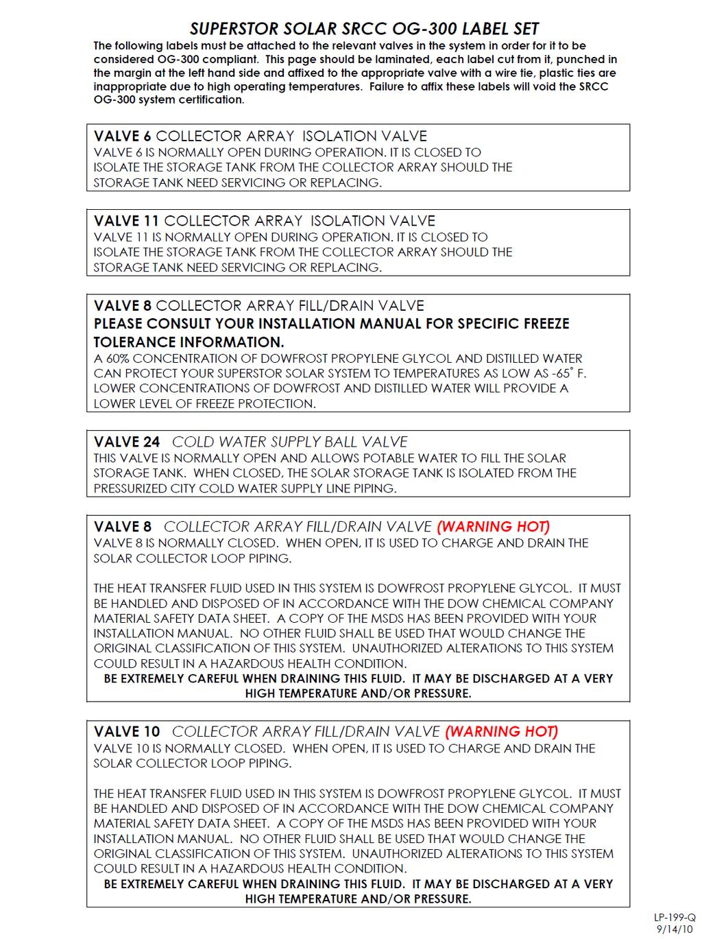
13 13 When making a connection to the heat exchanger, use Teflon Tape and joint compound to prevent leaks. The connections to the heat exchanger are 1 NPT. Do not apply heat directly to the heat exchanger thread connection when sweating fittings. Line pressure and temperature gauge shall be installed in the collector supply and return lines to allow for a simple diagnostic check of proper system operation. On a sunny day, the hot water return line should be approximately 5 12 o F warmer than the water in the collector supply line. Compare the temperature readings in the two line thermometers. The ¾ cold water supply line to the storage tank must be insulated with a minimum 7/8 x ½ pipe insulation to a minimum distance of 5 behind the storage tank, or to the wall if closer than 5. D. TANK SENSOR PLACEMENT Make sure the sensor is secured on the stud located in the lower section of the water heater. Secure the sensor by packing Rubatex insulation behind it. This will also help the sensor react to temperature change. Non-toxic freeze protection fluid must be used to protect the system from freezing. Use a mixture appropriate for your climate. Do not use a higher glycol to water concentration than necessary, as this will adversely impact heat transfer efficiency. See the DowFrost Data Sheet in the back of this manual for recommended concentrations. A copy of the MSDS sheet must be left with the end user of the solar system. See EMERGENCY OVERVIEW as part of the DowFrost Data Sheet in the back of this manual. The collector loop must be charged with a mixture of heat transfer fluid and distilled or deionized water. The use of regular tap water as a mixing agent is prohibited. Regular scheduled maintenance must be established to monitor and maintain the proper ph level of the heat transfer fluid in the system to protect the heat exchanger and other components in the system. E. NECESSARY COMPONENTS FOR SOLAR WATER HEATER INSTALLATION Listed below are components needed for installation of the solar water heater. Solar Collector Absorbs and transfers the sun s energy into the solar heat exchanger located on the bottom of the solar water heater. Solar Air Release Vent This air vent allows air contained in the solar system to release. The air vent valve must be designed to work in high temperatures (as high as 350 o F) with a glycol medium. (This is typical of solar systems.) Solar Collector Sensor This sensor is wired to the solar controller and automatically turns on the circulator pump when the differential set point is reached between the solar water heater and collector. Tank and Heat Exchanger Temperature and Pressure Gauge The temperature and pressure gauge on the solar piping will show the user the actual temperature and pressure supplied and returned to the solar collector. Check Valve Helps minimize convective heat loss at night when the system is not operating. If a check valve is not installed, most of the heater energy stored during the day would be transferred into the panel and lost. Collector Isolation Valve (Valve #6) Valve #6 and 11 (for solar collector isolation) isolates the collector loop from the solar water heater.
14 14 Pressure Relief Valve (for Solar System) Releases pressure in the solar loop when it exceeds 75psi. If the valve opens and releases fluids, contact your installation contractor immediately. System Fill Valve (Valve #8) Fills the system with heat transfer fluid. Also eliminates air from the system. Expansion Tank Pre-charged with air to allow for the expansion and contraction of heat transfer fluid. Drain Valve (Valve #10) Used to charge the collector loop with glycol, purge air from the loop and drain the solar water heater heat exchanger of fluid. Collector Isolation Valve (for system fill) (Valve #11) Used to direct the flow of heat transfer fluid and to pressurize and eliminate air from the solar system. Ball Valve (for circulator) Valve #12 Used to isolate the circulator pump for service. Close both ball valves to isolate pump. Circulator (#13) Circulates the heat transfer fluid from the solar collector into the solar heat exchanger. Drain Valve (Tank) (Valve #14) Flushes sediment which may accumulate on the bottom of the solar water heater and also provides a means of draining the tank. Tank Sensor Is wired to the solar controller to measure the temperature on the bottom of the solar water heater in conjunction with the solar collector sensor. Turns the circulating pump on and off at the solar control preset temperature differentials. Solar Controller The solar controller turns on or off the circulator depending on heat gained from solar operation. The controller also limits overheating in the solar water heater. Some controllers have various options. The controller should always be set in the auto position so that it operates the array automatically when there is solar energy to be collected. Solar Heat Exchanger The solar heat exchanger has an integral finned tube designed to transfer heated energy rapidly from the solar collector into potable water. The heat exchanger is constructed in 90/10 copper nickel for superior corrosion resistance and long-term reliability. Hot Water Outlet Each solar water heater has a hot water dip tube outlet which draws water from the top of the heater. This helps to keep heat trapped inside the highly insulated storage tank. Solar Tank Temperature and Pressure Relief Valve The relief valve must comply with standards for relief valves (ANSI Z21.22) by a nationally recognized lab that maintains periodic inspections of production listed equipment. No valve of any type should be installed between the relief valve and tank. Local codes govern installation of relief valves. The relief valve outlet must be piped to a suitable open drain so that the discharge water cannot contact live electric parts to eliminate potential damage. Piping used should be approved for hot water distribution. The discharge line must be no smaller than the outlet of the relief valve and must pitch
15 15 downward to allow complete drainage. The end of the discharge piping should not be threaded or concealed and must be protected from freezing. No valve of any type, restriction or reducer coupling should be installed in the discharge line. Mixing Valve (Rated ASSE 1017) Automatically blends the hot and cold water feed lines to control discharge to an acceptable and safe temperature. This also increases the amount of hot water that is drawn from the solar water heater by not allowing the incoming water to fully temper the hot water stored inside the tank. Ball Valve (for cold water shut-off) (Valve #24) The cold water shut off valve should be used in the event of an emergency shutdown. It is very important that you do the potable piping before you pipe into the solar system. Failure to do so may damage your water heater.
16 16 F. PHOENIX SOLAR PIPING WITH AIR HANDLER Figure 6 - This drawing is meant to demonstrate system piping concept only.
17 17 G. TANK CONTROL Install the solar sensor onto the threaded stud provided in the front of the water heater (sensor not included). Additional equipment may be needed in order to wire the control to the existing system. Controls also have the ability to monitor and display solar collector temperature and upper and lower tank temperatures. Figure 7 H. CIRCULATOR SIZING The circulator pump must be sized for the related piping and pressure drop of the heat exchanger. The graph in Figure 8 represents the pressure drop of the solar heat exchanger. You must consult the solar panel manufacturer for flow requirements to assist in pump selection Solar Heat Exchanger Pressure Drop Feet of friction Flow in Gallons per Minute Figure 8 Flow Chart LP-200-L
18 18 I.CHARGING THE SYSTEM Closed Loop Glycol Solar Tank Fill the solar tank with water. Do this by opening the cold water isolation ball valve to the solar tank. Inspect all fittings for leaks. The solar collector loop should be pressure tested with air (25 lbs.) before you pressurize the solar collector loop with glycol. Mix the DowFrost propylene glycol and distilled water in accordance with the data sheet in the back of the manual. The charging process will require a low flow diaphragm pump to fill and pressurize the collector loop. Solar Collector Connect the discharge side of the pressure pump to the fill valve. Place the pump suction side hose in the glycol solution. Close the ball valve (#11). Connect a second hose to the drain valve (#10) and place the other end of the hose in the empty bucket. TOTAL COLLECTOR LOOP FLUID CAPACITY IN GALLONS* 1. One Collector System 3.5 gallons 2. Two Collector System 4.5 gallons *Assumes a total 100 pipe run using ¾ Type M hard copper tubing. The solar heat exchanger has a 1.5 gallon fluid capacity. Open the upper fill valve (#18) and allow the pressure from the expansion tank to push the water in the glycol loop back to prime the pressure pump. When the hose in the bucket containing the glycol mixture stops bubbling, you may begin charging the collector loop with glycol. With both fill and drain valves open, run the low flow diaphragm pump until the glycol mixture begins flowing into the empty bucket. Quickly switch the hose from the empty/return bucket to the bucket containing the glycol mixture. Continue to circulate the fluid using the pressure pump until the bubbling has stopped and the air has been purged. After charging the collector loop, shut the lower drain valve (#10) and let the pressure pump drive up the loop pressure to the appropriate level (generally in the range of 25 psi). To more accurately calculate the proper pressure, measure the height of the solar collector above the tank and divide this number by 2.31, then add 20 psi to this number. The pressure in the glycol loop should not exceed 45 psi when the system is in operation on a sunny day. Contact your solar contractor if the collector loop exceeds the threshold. After pressurizing the solar system, run the circulator and allow the air to purge out of the vent. Once purged, monitor pressures and check for leaks before insulating pipes. Pressure should then be about 25 psi. Above ground piping must be insulated with a wall thickness of at least ¾. A 1 thickness is required in areas prone to hard freeze conditions. Above ground insulation must be protected from ultraviolet degradation. All piping must be supported at a maximum interval of 10 and the piping supports must not crimp or compress the insulation. J. COMMISSIONING THE SYSTEM Closed Loop Glycol After the glycol loop has been charged and pressure is around 25 psi (check gauge on solar heat exchanger) set the solar control to the desired settings. Solar controls come with default settings that will work in most installations. If it is a cloudy day, you may have to activate the circulator pump. Once the

19 19 pump is running and the system is fully purged, set the control to the desired settings. It is recommended that the storage tank high limit set point is not set any lower than 160 o F. A lower set point could lower the performance of the solar water heater and cause overheating of the collector system. You must install an anti-scald valve on the hot water outlet as temperature within the storage tank can cause injury please see warning label for outlet temperature restriction. PART 4: MAINTENANCE A properly maintained solar water heating system can provide years of dependable, trouble free service. It is suggested that a routine preventive maintenance program be established and followed by the end user with the contractor. Below is the maintenance check list that outlines the primary components of the solar system that need to be inspected annually. 1. Glycol It is very important that the quality of the glycol heat transfer fluid is maintained to avoid damage to the collector loop and related components which come in contact with the fluid. See the DowFrost data sheet located in the back of the manual for further details. 2. Over time, water quality can affect the operation of the solar heat exchanger. In very hard water areas, it is recommended you drain (#14) a few gallons from the tank to keep the bottom of the water heater free of sediment. 3. Clean and inspect the solar collector (#1). Dirt or film which may have settled on the surface may affect performance. Check collector supplier information for cleaning procedures. 4. Check insulation for deterioration. 5. Check solar tank sensors to assure they are secure and have not moved or loosened. 6. Inspect the T&P valve (#19) on the water heater. Lift the release handle lever and make sure discharge is directed to an open drain. 7. The area near the water heater must be kept free of flammable liquids such as gasoline, paint thinners, adhesive, or other combustible materials. A. SHUTDOWN PROCEDURES The solar system is designed to be easily isolated for emergency repairs or routine maintenance. To isolate the water heater, simply shut down supply water shut off valve (#21) which isolates the water heater from the pressurized cold water supply. The collector loop can be isolated from the solar storage tank by closing (#6 and #11). If the pressure in this loop drops, or you find a glycol leak, shut these valves and contact your installation contractor. Turn the circulating pump off on your solar control. B. VACATION SHUTDOWN Solar water heaters can build up very high temperatures when there is no daily draw on the system. The best way to dissipate heat in the system is set the control to run the circulator pump 24 hours a day to cool off the storage tank at night. The collector will radiate heat back to the atmosphere at night, preventing the system from stagnating at very high temperatures.
20 20 C. ESTIMATED LIFE OF COMPONENTS Proper care and maintenance will determine the life expectancy of the individual components of the solar system. Refer to manufacturer s warranty information to determine coverage of individual components. To obtain warranty service, call your local service or installing contractor. Following installation of the T&P Relief Valve, the valve lever MUST be operated AT LEAST ONCE A YEAR by the water heater owner to ensure that waterways are clear. Certain naturally occurring mineral deposits may adhere to the valve, blocking waterways and rendering the valve inoperative. When the lever is operated, hot water will discharge if the waterways are clear. PRECAUTIONS MUST BE TAKEN TO AVOID PERSONAL INJURY FROM CONTACT WITH HOT WATER AND TO AVOID PROPERTY DAMAGE. BEFORE operating lever, check to see that a discharge line is connected to the valve, directing the flow of hot water from the valve to a proper place of disposal. If no water flows when the lever is operated, replacement of the valve is required. TURN THE WATER HEATER OFF AND CALL A PLUMBER IMMEDIATELY. This device is designed for emergency safety relief and shall not be used as an operating control. A relief valve functions by discharging water in an emergency. Therefore, it is essential that a discharge line be piped from the valve in order to carry the overflow to a safe place of disposal. The discharge line must be the same size as the valve outlet, must pitch downward from the valve, and terminate at least 6 above a drain where any discharge will be clearly visible.
21 Figure 9 LP-204-L 21
22 Figure 10 22
23 Figure 11 23
24 24 PART 5: TROUBLESHOOTING NATURE OF TROUBLE POSSIBLE CAUSE SERVICE No hot water 1. No power blown fuse or circuit breaker tripped a. Shorted wiring b. Circuit overloaded c. Improper wiring d. Grounded element or thermostat 2. Manual reset limit (ECO) open a. Thermostat defective b. Thermostat out of calibration c. Heat build-up due to loose wires d. Defective limit (ECO) 3. Solar system incorrectly installed 4. Leaking plumbing or open hot water faucet(s) a. **Replace or repair b. **Provide adequate circuit or reduce load c. **Rewire per diagram d. **Replace Refer to Operation Section a. **Replace b. **Lower setting or replace c. **Tighten wire connections d. **Replace **Check installation Make sure all faucet(s) are closed and check water meter Not enough hot water 1. Heater undersized Reduce rate of hot water use 2. Defective thermostat or wired **Check wiring or replace incorrectly Water too hot or not hot enough Table 1 3. Solar system incorrectly installed 4. See #4 above (in No hot water) **Check installation See above 1. Thermostat setting too high or Change setting as required low 2. Thermostat out of calibration **Replace 3. Solar system incorrectly **Check installation installed 4. Grounded element **Replace **For your safety, DO NOT attempt repair of electrical wiring, thermostat or operating controls. Refer repairs to qualified service personnel.

25 25

26 26
27 27 VISCOSITY: The HTF viscosity over the service temperature range is based on a specific gravity 15/15 o C (60/60 o F) DOWFROST inhibited glycol-based fluid has an effective operating temperature range of -50 o F to 250 o F. At temperatures below -50 o F, increased viscosity (>1,000 centipoise) can make use of DOWFROST impractical unless larger pumps are installed. At the upper end of the operating range for DOWFROST fluid, a maximum bulk temperature of 250 o F is recommended. Film temperature should not exceed 300 o F. DOWFROST fluid can tolerate brief temperature excursions up to 100 o F above the maximum recommended temperatures. However, extended exposure of the fluid to temperatures in excess of 50 o F above the maximum recommended temperatures will result in accelerated degradation of the glycol and inhibitor systems. In addition, the film temperature should remain within 50 o F of the bulk fluid temperature and the pressure at all points in the system should be at least 5 psi greater than the vapor pressure exerted by the fluid to avoid localized boiling and resulting precipitation. At temperatures above 150 o F, the system must be closed to avoid rapid oxidation of the propylene glycol, inhibitor depletion, and subsequent increased corrosion. Automatic make-up water systems should be avoided in order to prevent undetected dilution or loss of glycol and consequent loss of freeze and corrosion protection. FLAMMABILITY: When mixed with water, DOWFROST is not flammable, as the fluid has no measurable flash point (Pensky-Martens Closed Cup) in concentrations up to 80% glycol. Undiluted DOWFROST has a flash point of 214 o F (Pensky-Martens Closed Cup). It is possible to ignite solutions of propylene if enough water has been vaporized and the concentration of propylene glycol increases to greater than 80 percent. INSPECTION AND TREATMENT OF HEAT TRANSFER FLUID: You can quickly determine the condition of your fluid by examining its appearance and odor. Any drastic variation from the initial fluid specifications, such as a black or dark-grey color, presence of an oily layer, burnt odor, or any heavy sludge in the fluid may indicate the need for replacement. TESTING THE FLUID ph LEVEL: Control of ph between 8 and 10 is important to minimize corrosion and glycol degradation. Using narrow range ph paper, such as phydrion Control paper with a 7.2 to 8.8 ph range, is an easy and reliable way to read your ph level. A ph tester can also measure alkalinity or acidity and give you an indication of the reserve alkalinity or inhibitor level of the fluid. The desirable ph range should fall between 8.0 and Adjustments can be made using a 50% solution of sodium hydroxide or potassium hydroxide if the ph is approaching the acidic range (below 8.0). An inexpensive ph tester is available from Misco Products. The accuracy of this product is +/- 0.5 ph. Contact Misco Products at and ask for the Dow discount. SPILL, LEAK, AND DISPOSAL PROCEDURES: Using appropriate safety equipment, small spills may be soaked up with common absorbent material. For large spills, the fluid should be pumped into suitable containers located in diked areas. Residual material should be cleaned up with water. Concentrate can be handled according to local, state, and federal regulations. EMERGENCY OVERVIEW POTENTIAL HEALTH EFFECTS EYE: May cause slight transient (temporary) eye irritation. Corneal injury is unlikely. Mists may cause eye irritation. FIRST AID: FLUSH EYES WITH PLENTY OF WATER SKIN CONTACT: Prolonged contact is essentially non-irritating to skin. A single prolonged exposure is not likely to result in the material being absorbed through the skin in harmful amounts. Repeated exposure may cause flaking and softening of skin.
28 28 FIRST AID: WASH OFF IN FLOWING WATER OR SHOWER INGESTION: Single dose oral toxicity is considered to be extremely low. No hazards anticipated from swallowing small amounts incidental to normal handling operations. FIRST AID: NONE REQUIRED INHALATION: At room temperature, vapors are minimal due to physical properties. Mists may cause irritation of upper respiratory tract (nose and throat). FIRST AID: REMOVE TO FRESH AIR. IF EFFECTS OCCUR, CONSULT A PHYSICIAN. NOTE TO PHYSICIAN: NO SPECIFIC ANTIDOTE. SUPPORTIVE CARE. TREATMENT BASED ON JUDGEMENT OF THE PHYSICIAN IN RESPONSE TO THE REACTION OF THE PATIENT. CONSULT DOW CHEMICAL 24 HOUR EMERGENCY SYSTEM MODELS SOLAR COLLECTOR COMPANY MODEL # OF COLLECTORS PH-80 HTP HP-30-SC 1 AET AE32E 1 SUN EARTH EP-32 1 APRICUS AP-22 1 Table 2 PH-119 HTP HP-30-SC 2 AET AE32E 2 SUN EARTH EP-32 2 APRICUS AP-22 2 SOLAR SYSTEM REPLACEMENT PARTS Part Company Model STECA TRO301 CONTROLLER GOLDLINE GL-30 HELIOTROPE Thermal Delta T PUMP TACO OO7 GRUNDFOS 15-58F EXPANSION TANK AMTROL Extrol #30 CHECK VALVE WATTS SERIES 600* *(ALTERNATE APPROVED EQUIVALENT) PRESSURE RELIEF VALVE WATTS 3L (75 psig) AIR VENT TACO 417* *(ALTERNATE APPROVED EQUIVALENT) TACO 500 SERIES MIXING VALVE WATTS 1170 SERIES HONEYWELL AM101 SERIES CACHE ACAC HEATGUARD 110 SERIES Table 3
29 29
30 MAINTENANCE NOTES 30
31 31 HTP CUSTOMER INSTALLATION RECORD FORM The following form should be completed by the installer for you to keep as a record of the installation in case of a warranty claim. After reading the important notes at the bottom of the page, please also sign this document. Customer s Name: Installation Address: Date of Installation: Installer s Code/Name: Product Serial Number(s): Comments: Installer s Phone Number: Signed by Installer: Signed by Customer: IMPORTANT NOTES: Customer: Please only sign after the installer has reviewed the installation, safety, proper operation and maintenance of the system. In the case that the system has any problems, please call the installer. If you are unable to make contact, please contact your HTP Sales Representative. Distributor/Dealer: Please insert contact details. LP- 204 REV
SB SERIES SE SERIES. Installation Operation Maintenance WITH BACK-UP HEAT EXCHANGER WITH BACK-UP ELECTRIC ELEMENT E113265
 E113265 Installation Operation Maintenance SB SERIES WITH BACK-UP HEAT EXCHANGER SE SERIES WITH BACK-UP ELECTRIC ELEMENT The solar energy system described in this manual, when properly installed and maintained,
SuperStor Ultra Stainless Steel Storage Tank
 SuperStor Ultra Stainless Steel Storage Tank INSTALLATION START-UP MAINTENANCE PARTS Storage Tank Models SSU-30CB / SSU-45CB SSU-60CB / SSU-80CB / SSU-119CB For Residential and Commercial Use This manual
SuperStor Glass Lined Storage Tank
 SuperStor Glass Lined Storage Tank INSTALLATION MAINTENANCE TROUBLESHOOTING PARTS Storage Tank Models GL-50 / GL-80* GL-119* / GL-175* For Residential and Commercial Use *Available in Metal Jacketed ASME
Phoenix / Versa-Hydro Solar Supplement
 Phoenix / Versa-Hydro Solar Supplement INSTALLATION OPERATION MAINTENANCE TROUBLESHOOTING Phoenix Models Versa-Hydro Models PH130-80S / 130-119S PHE130-80S / 130-119S PH199-80S / 199-119S PHE199-119S /
SuperStor Contender Indirect Fired Water Heater
 SuperStor Contender Indirect Fired Water Heater INSTALLATION START-UP MAINTENANCE PARTS SuperStor Contender Water Heater Models SSC-35 / SSC-50 / SSC-80 / SSC-119* *NOTE: A suffix of S denotes Solar Model
Installation & Operation Manual Models: TSU
 TSU-I-O Rev A Installation & Operation Manual Models: TSU 150-940 CAUTION: This appliance is not intended for potable water. This manual must only be used by a qualified heating installer / service technician.
SOLARHOT. SuperVox. Description / Applications System Overview. Installation/ Owner s Manual
 SOLARHOT SuperVox Installation/ Owner s Manual Description / Applications System Overview The SOLARHOT SuperVox solar thermal glycol system. The SuperVox allows for easy installation of large solar water
NOTE TO CONSUMER: PLEASE KEEP ALL INSTRUCTIONS FOR FUTURE REFERENCE.
 SuperStor Pro Solar Solar Supplement Installation Start-Up Maintenance Parts Warranty For Residential and Commercial Use SE Series Models* *SE Denotes Back-Up Electric Element The solar energy system described
Use & Care Manual. ! Recognize this symbol as an. ! California Proposition 65 Warning:
 Use & Care Manual With Installation Instructions for the Installer Pumped Solar Water Heating Systems The purpose of this manual is twofold: one, to provide the installer with the basic directions and
NOTE TO CONSUMER: PLEASE KEEP ALL INSTRUCTIONS FOR FUTURE REFERENCE.
 SuperStor Solar Supplement Installation Start-Up Maintenance Parts Warranty For Residential and Commercial Use SB Series and SE Series Models* *SB Denotes Back-Up Heat Exchanger SE Denotes Back-Up Electric
NOTE TO CONSUMER: PLEASE KEEP ALL INSTRUCTIONS FOR FUTURE REFERENCE.
 Direct Fired Solar Supplement Installation Start-Up Maintenance Parts Warranty For Residential and Commercial Use Phoenix and Versa Hydro Solar Models The solar energy system described in this manual,
Pumped Solar Water Heating Systems
 Use & Care Manual With Installation Instructions for the Installer Pumped Solar Water Heating Systems The purpose of this manual is twofold: one, to provide the installer with the basic directions and
INDIRECT FIRED WATER HEATERS
 H E A T T R A N S F E R P R O D U C T S INDIRECT FIRED WATER HEATERS RESIDENTIAL COMMERCIAL Heat Transfer Products, Inc., reserves the right to make product changes or updates without notice. Heat Transfer
NOTE TO CONSUMER: PLEASE KEEP ALL INSTRUCTIONS FOR FUTURE REFERENCE.
 Drain Back Tank Installation Start-Up Maintenance Parts Warranty For Residential and Commercial Use DB Series and DBX Models* *A suffix of X denotes models with internal heat exchanger This manual must
INSTALLATION INSTRUCTIONS & HOME OWNERS MANUAL ECO 18 ECO 24 ECO 27 IMPORTANT SAFETY INFORMATION
 INSTALLATION INSTRUCTIONS & HOME OWNERS MANUAL ECO 18 ECO 24 ECO 27 IMPORTANT SAFETY INFORMATION As when installing or using any high voltage electrical appliance, basic safety precautions should always
Pumped Solar Water Heating Systems
 Use & Care Manual With Installation Instructions for the Installer Pumped Solar Water Heating Systems The purpose of this manual is twofold: one, to provide the installer with the basic directions and
Use & Care Manual. With Installation Instructions for the Installer Pumped Solar Water Heating Systems AP (04/11)
") Use & Care Manual With Installation Instructions for the Installer Pumped Solar Water Heating Systems The purpose of this manual is twofold: one, to provide the installer with the basic directions and
Use & Care Manual With Installation Instructions for the Installer Pumped Solar Water Heating Systems The purpose of this manual is twofold: one, to provide the installer with the basic directions and
Use & Care Manual. Electric Tankless Water Heaters. With Installation Instructions for the Installer AP15447 (10/10)
") Use & Care Manual With Installation Instructions for the Installer Electric Tankless Water Heaters The purpose of this manual is twofold: one, to provide the installer with the basic directions and recommendations
Use & Care Manual With Installation Instructions for the Installer Electric Tankless Water Heaters The purpose of this manual is twofold: one, to provide the installer with the basic directions and recommendations
CodeNotes. Solar Water Heating Systems Based on the 2015 International Solar Energy Provisions. Introduction. Solar Water Heating System Designs
 CodeNotes is provided courtesy of the ICC PMG Official Membership Council CodeNotes Solar Water Heating Systems Based on the 2015 International Solar Energy Provisions Introduction Solar water heating
HOMEADVANTAGE II IMPORTANT SAFETY INFORMATION
 INSTALLATION INSTRUCTIONS & HOME OWNERS MANUAL HOMEADVANTAGE II HA008240 HA011240 HA013240 HA018240 HA024240 HA027240 HA036240 IMPORTANT SAFETY INFORMATION When installing or using any high voltage electrical
Installation & Operation Manual Models:
 SJS-I-O Rev C Installation & Operation Manual Models: 60-119 : If the information in this manual is not followed exactly, a fire or explosion may result causing property damage, personal injury or loss
ELECTRIC WATER HEATER INSTALLATION & OPERATING INSTRUCTION MANUAL
 ELECTRIC WATER HEATER INSTALLATION & OPERATING INSTRUCTION MANUAL THE MANUFACTURER OF THIS HEATER WILL NOT BE LIABLE FOR ANY DAMAGE RESULTING FROM FAILURE TO COMPLY WITH THESE INSTRUCTIONS. READ THESE
CodeNotes. Solar Water Heating Systems Based on the 2018 International Solar Energy Provisions (ISEP ) Introduction OFFICIAL
 Introduction OFFICIAL") CodeNotes is provided courtesy of the ICC PMG Official Membership Council OFFICIAL CodeNotes Solar Water Heating Systems Based on the 2018 International Solar Energy Provisions (ISEP ) Introduction Solar
CodeNotes is provided courtesy of the ICC PMG Official Membership Council OFFICIAL CodeNotes Solar Water Heating Systems Based on the 2018 International Solar Energy Provisions (ISEP ) Introduction Solar
User s Information Manual
 User s Information Manual Gas-Fired Storage Water Heater, Tankless Water Heater, Heating Appliance, and Combination Appliance Models IF THE INFORMATION IN THIS MANUAL IS NOT FOLLOWED EXACTLY, A FIRE OR
CLOSED LOOP DOMESTIC HOT WATER SOLAR SYSTEM WITH DIFFERENTIAL CONTROL
 CLOSED LOOP DOMESTIC HOT WATER SOLAR SYSTEM WITH DIFFERENTIAL CONTROL MODELS SLCR60DC-80HE, SLCR64DC-80HE, SLCR80DC-80HE, SLCR40DC-80HE & SLCR32DC-80HE INSTALLATION MANUAL Solene 927 Fern St. Suite 1500
INSTALLATION & SERVICE MANUAL
 INSTALLATION & SERVICE MANUAL ELECTRIC WATER HEATER THE WARRANTY ON THIS WATER HEATER IS IN EFFECT ONLY WHEN THE WATER HEATER IS INSTALLED AND OPERATED IN ACCORDANCE WITH LOCAL CODES AND THESE INSTRUCTIONS.
Universal Fire Tube Boiler Wall Mount Models
 Universal Fire Tube Boiler Wall Mount Models USER S INFORMATION MANUAL Models WBRU**80W / 100W / 120W / 140W / 175W / 199W **NG denotes Natural Gas Model, LP Denotes Propane Model Heat Exchanger Bears
Residential Gas Hybrid Water Heater
 Residential Gas Hybrid Water Heater USER S INFORMATION MANUAL WGRGH20NG75F / WGRGH20NG76F / WGRGH20NG100F WGRGHNG75F / WGRGHNG76F / WGRGHNG100F Models* *A suffix of LP denotes propane gas NOTICE: Westinghouse
SuperStor Ultra Indirect Fired Water Heaters
 SuperStor Ultra Indirect Fired Water Heaters INSTALLATION START-UP MAINTENANCE PARTS For Residential and Commercial Use This manual must only be used by a qualified installer/service technician. Read all
Water Heaters. Use & Care Manual. Electric Residential. With Installation Instructions for the Installer. Double Element Residential Electric Models
 Use & Care Manual With Installation Instructions for the Installer Electric Residential Water Heaters Double Element Residential Electric Models The purpose of this manual is twofold: one, to provide the
Niles Steel Tank Hot Water Generator Installation and Operation Manual
 Niles Steel Tank Hot Water Generator Installation and Operation Manual Contents: Contents 1 Hazard definitions 1 1. General Information.... 2 Availability... 3 Optional Control Packages... 5 2. Installation....
OPERATING AND MAINTENANCE MANUAL FOR ELECTRIC STAINLESS STEEL HEATER FOR DEIONIZED (DI) WATER ELECTRIC HEATER COMPANY BASE MODEL D
 WATER ELECTRIC HEATER COMPANY BASE MODEL D") OPERATING AND MAINTENANCE MANUAL FOR ELECTRIC STAINLESS STEEL HEATER FOR DEIONIZED (DI) WATER ELECTRIC HEATER COMPANY BASE MODEL D HUBBELL ELECTRIC HEATER COMPANY P.O. BOX 288 STRATFORD, CT 06615 PHONE:
OPERATING AND MAINTENANCE MANUAL FOR ELECTRIC STAINLESS STEEL HEATER FOR DEIONIZED (DI) WATER ELECTRIC HEATER COMPANY BASE MODEL D HUBBELL ELECTRIC HEATER COMPANY P.O. BOX 288 STRATFORD, CT 06615 PHONE:
Gas Fired Residential Combi Boiler Floor and Wall Mount Models
 Gas Fired Residential Combi Boiler Floor and Wall Mount Models USER S INFORMATION MANUAL Models WBRC**140W WBRC**199W WBRC**140F WBRC**199F ** NG Refers to Natural Gas Operation LP Refers to Propane Gas
MC Series Gas-Fired Circulating Heater
 MC Series Gas-Fired Circulating Heater INSTALLATION START-UP MAINTENANCE PARTS Models MC50 / MC80 MC99 / MC120 When installing models manufactured after July 7, 2008, you will notice additional selections
Residential Solar Water Heater with Heat Exchanger. Solariade Water Heater with Heat Exchanger (Front View)
") Residential Solar Water Heater with Heat Exchanger USE & CARE MANUAL WITH INSTALLATION INSTRUCTIONS FOR THE CONTRACTOR LISTED 786H Solariade Water Heater with Heat Exchanger (Front View) The purpose of
Residential Solar Water Heater with Heat Exchanger USE & CARE MANUAL WITH INSTALLATION INSTRUCTIONS FOR THE CONTRACTOR LISTED 786H Solariade Water Heater with Heat Exchanger (Front View) The purpose of
INSTALLATION & MAINTENANCE MANUAL FOR QuickDraw
 INSTALLATION & MAINTENANCE MANUAL FOR QuickDraw SEMI-INSTANTANEOUS ENERGY: STEAM TO WATER U-TUBE SINGLE-WALL & DOUBLE-WALL HEAT EXCHANGERS FLOOR DRAIN Typical Construction Figure 34-1 FLOOR DRAIN 1. U-tube
INSTALLATION INSTRUCTIONS & HOME OWNERS MANUAL AUTOBOOSTER IMPORTANT SAFETY INFORMATION
 INSTALLATION INSTRUCTIONS & HOME OWNERS MANUAL AUTOBOOSTER IMPORTANT SAFETY INFORMATION When installing or using any high voltage electrical appliance, basic safety precautions should always be followed.
USE & CARE MANUAL. Residential Solar Water Heater with Heat Exchanger WITH INSTALLATION INSTRUCTIONS FOR THE CONTRACTOR
 Residential Solar Water Heater with Heat Exchanger USE & CARE MANUAL ALTERNATE-ENERGY WATER-STORAGE TANK 52L6 WITH INSTALLATION INSTRUCTIONS FOR THE CONTRACTOR The purpose of this manual is twofold: one,
Oil-Fired Water Heater
 Oil-Fired Water Heater INSTALLATION MANUAL NOTICE: HTP reserves the right to make product changes or updates without notice and will not be held liable for typographical errors in literature. 120 Braley
INSTALLATION OPERATION MAINTENANCE
 SOLAR WATER HEATER Instruction Manual INSTALLATION OPERATION MAINTENANCE The Solar Water Heater has been sold as a component part. It has been factory equipped with a booster element, and thermostat with
PRO SERIES IMPORTANT SAFETY INFORMATION
 INSTALLATION INSTRUCTIONS & HOME OWNERS MANUAL PRO SERIES IMPORTANT SAFETY INFORMATION When installing or using any high voltage electrical appliance, basic safety precautions should always be followed.
INSTALLATION, OPERATION AND MAINTENANCE MANUAL FOR COMMERCIAL INDIRECT POWERED WATER HEATER
 INSTALLATION, OPERATION AND MAINTENANCE MANUAL FOR COMMERCIAL INDIRECT POWERED WATER HEATER ELECTRIC HEATER COMPANY BASE MODEL T Edition 0 HUBBELL ELECTRIC HEATER COMPANY P.O. BOX 88 STRATFORD, CT 0665
SEISCO SUPERCHARGER EXTENDER/BOOSTER INSTALLATION GUIDE & OWNERS MANUAL
 SEISCO SUPERCHARGER EXTENDER/BOOSTER INSTALLATION GUIDE & OWNERS MANUAL This manual is provided as a guide to installation. All installations must comply with any and all local and national electrical
Product Manual. Companion Water Heater. Maintenance Parts. Installation Startup. for WM97+ Gas-Fired Boilers
 Companion Water Heater for WM97+ Gas-Fired Boilers Product Manual Installation Startup Maintenance Parts High Performance Companion Water Heater (Boiler sold separately) This manual must only be used by
GEOTHERMAL STORAGE TANKS
 GEOTHERMAL STORAGE TANKS INSTALLATION OPERATION MAINTENANCE Instruction Manual The storage tank is sold as a component part. It has been factory equipped with a booster element, and thermostat with high
INSTALLATION INSTRUCTIONS GEO PRIME TANK. (Patent Pending) GPC
 GPC") INSTALLATION INSTRUCTIONS GEO PRIME TANK (Patent Pending) GPC Table of Contents General Description 2 Installation 3 Flushing and Purging 5 Initial Start up 7 Adding or Checking Fluid 8 Replacing a Pump
INSTALLATION INSTRUCTIONS GEO PRIME TANK (Patent Pending) GPC Table of Contents General Description 2 Installation 3 Flushing and Purging 5 Initial Start up 7 Adding or Checking Fluid 8 Replacing a Pump
INSTALLATION and OPERATION MANUAL DIRECT STEAM KETTLES MOUNTED ON ELECTRIC BOILER BASE CABINET MODELS: EMT-6 EMT-10 EMT-12 EMT-6-6 EMT-10-6 EMT-10-10
 INSTALLATION and OPERATION MANUAL DIRECT STEAM KETTLES MOUNTED ON ELECTRIC BOILER BASE CABINET MODELS: EMT-6 EMT-10 EMT-12 EMT-6-6 EMT-10-6 EMT-10-10 CROWN FOOD SERVICE EQUIPMENT LTD. 70 OAKDALE ROAD,
Everlast Electric. Water Heaters. Use and Care Manual. Installation. Start-Up. Maintenance. Parts. Warranty. Residential EVR Models
 Use and Care Manual Installation Start-Up Maintenance Parts Warranty Everlast Electric Water Heaters Residential EVR Models This manual must only be used by a qualified installer / service technician.
INSTALLATION MANUAL GEO-BOOST GROUND LOOP HEAT EXCHANGER
 1103 N HIGH CROSS RD URBANA, IL 61802 1-773-492-1893 INSTALLATION MANUAL GEO-BOOST GROUND LOOP HEAT EXCHANGER REV 1.0 The Geo-Boost system consists of the Geo-Boost heat exchanger and a relay controller
WATLOW IND. WATROD Circulation Heater Installation & Maintenance Manual I&M NUMBER: Page: 1 Date: 6/11/2008 Rev: 2.00
 I&M NUMBER: 316-42-5-1 Page: 1 Pre Installation Check to make sure that heater received is the same as that ordered. Watlow heaters are built to comply with UL and CSA dielectric requirements, it may be
DRAINBACK DOMESTIC HOT WATER SOLAR SYSTEM WITH DIFFERENTIAL CONTROL MODELS SLCR60DC-80DB, SLCR64DC-80DB, SLCR80DC-80DB SLCR40DC-80DB & SLCR32DC-80DB
 DRAINBACK DOMESTIC HOT WATER SOLAR SYSTEM WITH DIFFERENTIAL CONTROL MODELS SLCR60DC-80DB, SLCR64DC-80DB, SLCR80DC-80DB SLCR40DC-80DB & SLCR32DC-80DB INSTALLATION MANUAL Solene 927 Fern St. Suite 1500 Altammonte
OPERATING AND INSTALLATION MANUAL
 OPERATING AND INSTALLATION MANUAL TANKLESS ELECTRIC WATER HEATER WITH ELECTRO-MECHANICAL FLOW SWITCH» MINI 2» MINI 2.5» MINI 3» MINI 3.5» MINI 4» MINI 6 The Mini series is tested and certified by WQA against
SOLENE INSTALLATION MANUAL OPEN LOOP HOT WATER SOLAR SYSTEM WITH DIFFERENTIAL CONTROL
 SOLENE INSTALLATION MANUAL OPEN LOOP HOT WATER SOLAR SYSTEM WITH DIFFERENTIAL CONTROL MODELS: SLAR32DC-66, SLAR40DC-80, SLAR64DC-120, SLAR80DC-120, SLAR30DC-66, SLAR32DC-80, SLSG40DC-80, SLSG80DC-120 Before
Tankless Water Heater
 Tankless Water Heater USER S INFORMATION MANUAL Models WGRT**150 / WGRT**199 / WGRTC**199 **A suffix of LP denotes propane gas **A suffix of NG denotes natural gas NOTICE: Westinghouse reserves the right
INSTANT HOT WATER DISPENSER
 INSTANT HOT WATER DISPENSER Tank Installation Materials required (not provided) 2 mounting bracket screws (and 2 plastic anchors if attaching to drywall) Shut-Off valve and T fitting Components When you
STORAGE TANK INSTALLATION and OPERATION MANUAL
 LST-I-O 100161529_2000014416 Rev F STORAGE TANK INSTALLATION and OPERATION MANUAL LOW LEAD CONTENT The information contained in this manual is intended for use by qualified professional installers, or
OPERATING AND INSTALLATION MANUAL
 OPERATING AND INSTALLATION MANUAL TANKLESS ELECTRIC WATER HEATER WITH ELECTRO-MECHANICAL FLOW SWITCH» MINI 2» MINI 2.5» MINI 3» MINI 3.5» MINI 4» MINI 6 The Mini series is tested and certified by WQA against
Residential Solar Water Heater
 Residential Solar Water Heater Residential Solar Water Heater Application Instructions Measure Description: Solar water heating or solar hot water is water heated by the use of solar energy. Solar heating
Indirect Fired Water Heaters
 Indirect Fired Water Heaters Installation and Operating Manual C US Models: SST150-40 SST250-65 SST300-80 SST450-119 CAUTION: The heat transfer medium must be water or other nontoxic fluid having a toxicity
NOTICE: HTP reserves the right to make product changes or updates without notice and will not be held liable for typographical errors in literature.
 Versa-Hydro INSTALLATION START-UP MAINTENANCE PARTS Versa-Hydro Water Heater Models* PHE130-55 / 199-55 PHE130-80 / 199-80 PHE130-119 / 199-119 *A suffix of LP denotes propane gas S indicates solar models
GOLD Plus 30/40/60/80
 PLUS Line Indirect-Fired Water Heaters Series 3 Manual Installation Startup Maintenance Parts PLUS 100/110/119 GOLD Plus 30/40/60/80 Plus 40/60/80 This manual must only be used by a qualified heating installer/service
Sun Bandit Hybrid Water Heater Installation and Operation Solar Hybrid Energy Systems Patent(s) Pending
 Pending") Solar Hybrid Energy Systems Patent(s) Pending Sun Bandit Hybrid Water Heater Installation and Operation Solar Hybrid Energy Systems Patent(s) Pending Instruction Manual Solar Hybrid Energy Systems Patent(s)
Solar Hybrid Energy Systems Patent(s) Pending Sun Bandit Hybrid Water Heater Installation and Operation Solar Hybrid Energy Systems Patent(s) Pending Instruction Manual Solar Hybrid Energy Systems Patent(s)
4201 Lien Rd Madison, WI Owner s Manual Therma-Stor III Heat Recovery System. Installation, Operation & Service Instructions
 4201 Lien Rd Madison, WI 53704 TS-140F Revised 09-10 Owner s Manual Therma-Stor III Heat Recovery System Installation, Operation & Service Instructions Read and Save These Instructions Table Of Contents
NOTICE: HTP reserves the right to make product changes or updates without notice and will not be held liable for typographical errors in literature.
 Versa-Hydro INSTALLATION START-UP MAINTENANCE PARTS Versa-Hydro Water Heater Models* PHE130-55 / 199-55 PHE130-80 / 199-80 PHE130-119 / 199-119 *A suffix of LP denotes propane gas S indicates solar models
Superstor Ultra NOTE TO CONSUMER: PLEASE KEEP ALL INSTRUCTIONS FOR FUTURE REFERENCE.
 Superstor Ultra Indirect Fired Installation Water Heaters Start-Up Maintenance Parts Warranty For Residential and Commercial Use SSU Models The surfaces of these products contacted by potable (consumable)
DOUBLE O-RING GEO-PRIME TANK Non-Pressurized Flow Center System INSTALLATION INSTRUCTIONS. Model: DORGPT-1 NOTE:
 INSTALLATION INSTRUCTIONS DOUBLE O-RING GEO-PRIME TANK Non-Pressurized Flow Center System Model: DORGPT-1 NOTE: This guide provides the installer with instructions specific to the Bard Double O-Ring Geo-Prime
INSTALLATION INSTRUCTIONS & HOME OWNERS MANUAL TANKBUDDY IMPORTANT SAFETY INFORMATION
 INSTALLATION INSTRUCTIONS & HOME OWNERS MANUAL TANKBUDDY IMPORTANT SAFETY INFORMATION When installing or using any high voltage electrical appliance, basic safety precautions should always be followed.
General System Layout Sketch
 General System Layout Sketch EZ-37 Solar Panels PV panel Glycol Fill Valve Expansion Tank ` 1 Introduction This document describes how to install a Heliatos GH type solar water heating system. These systems
Solar Storage Tank with Electric Backup Instruction Manual
 To the Installer: Please attach these instructions next to the water heater. To the Consumer: Please read these and all component instructions and keep for future reference. Solar Storage Tank with Electric
WMHP Series R410a Heat Pump INSTALLATION INSTRUCTIONS
 WMHP Series R410a Heat Pump INSTALLATION INSTRUCTIONS **WARNING TO INSTALLER, SERVICE PERSONNEL AND OWNER** Altering the product or replacing parts with non authorized factory parts voids all warranty
Heat Transfer Products, Inc. 120 Braley Road East Freetown, MA The first totally integrated multiple boiler management control.
 Heat Transfer Products, Inc. 120 Braley Road East Freetown, MA 02717 The first totally integrated multiple boiler management control. USING THIS MANUAL USING THIS MANUAL A. INSTALLATION SEQUENCE Follow
User s Information Manual
 User s Information Manual Gas-Fired Water Boilers With or without Aqua Logic (CWH) Now available Matching High Performance Companion Water Heater (Unit sold separately) If the information in this manual
INSTALLATION, OPERATING & MAINTENANCE INSTRUCTIONS FOR 350 SERIES CIRCULATION HEATERS
 INDEECO Circulation Heaters are designed to provide years of trouble free operation if properly installed and maintained. Please read and follow these instructions for installing and maintaining the heater.
INSTALLATION MANUAL GEO-BOOST GROUND LOOP HEAT EXCHANGER
 INSTALLATION MANUAL GEO-BOOST GROUND LOOP HEAT EXCHANGER Build Equinox support@buildequinox.com (773)-492-1893 Rev 2.0-05/10/2018 Build Equinox 2018 The Geo-Boost system consists of the Geo-Boost heat
TWO GALLON ELECTRIC WATER HEATER INSTALLATION & OPERATING INSTRUCTION MANUAL
 TWO GALLON ELECTRIC WATER HEATER A Spanish language version of these instructions is available by contacting the manufacturer listed on the rating plate. La version Espanola de estas instrucctions se puede
COMMERCIAL ELECTRIC WATER HEATER OWNER S MANUAL OPERATION AND MAINTENANCE INSTRUCTIONS
 COMMERCIAL ELECTRIC WATER HEATER OWNER S MANUAL OPERATION AND MAINTENANCE INSTRUCTIONS Make sure to follow the instructions mentioned in this manual in order AVERTISSEMENT to reduce the risk of fire, explosion,
SMARTBOOST IMPORTANT SAFETY INFORMATION
 INSTALLATION INSTRUCTIONS & HOME OWNERS MANUAL SMARTBOOST IMPORTANT SAFETY INFORMATION When installing or using any high voltage electrical appliance, basic safety precautions should always be followed.
INSTALLATION, OPERATION AND MAINTENANCE MANUAL FOR COMPACT POINT-OF-USE ELECTRIC WATER HEATER
 INSTALLATION, OPERATION AND MAINTENANCE MANUAL FOR COMPACT POINT-OF-USE ELECTRIC WATER HEATER BASE MODEL CE110 2015 Edition HUBBELL ELECTRIC HEATER COMPANY P.O.BOX 288 STRATFORD, CT 06615 PHONE: (203)
WATLOW IND. WATROD Flange Heater Installation & Maintenance Manual I&M NUMBER: Page: 1 Date:6/11/2008 Rev: 2.00
 I&M NUMBER: 316-42-8-1 Page: 1 _ Pre Installation Check to make sure that heater received is the same as that ordered. Elements may come in contact with each other during shipment. Minor adjustments to
Sun Bandit Solar Hybrid Electric Water Heater Solar Hybrid Energy Systems Patent(s) Pending. Installation, Operation and Maintenance Manual IMPORTANT!
 Pending. Installation, Operation and Maintenance Manual IMPORTANT!") Solar Hybrid Energy Systems Patent(s) Pending Sun Bandit Solar Hybrid Electric Water Heater Solar Hybrid Energy Systems Patent(s) Pending Installation, Operation and Maintenance Manual Solar Hybrid Energy
Solar Hybrid Energy Systems Patent(s) Pending Sun Bandit Solar Hybrid Electric Water Heater Solar Hybrid Energy Systems Patent(s) Pending Installation, Operation and Maintenance Manual Solar Hybrid Energy
PURCHASED. IF YOU ARE UNSUCCESSFUL, PLEASE WRITE TO THE COMPANY LISTED ON THE RATING PLATE ON THE WATER HEATER.
 Instruction Manual SOLAR WATER HEATING SYSTEMS WITH SINGLE WALL HEAT EXCHANGER AND GAS BACKUP FOR POTABLE WATER HEATING ONLY Low Lead Content Canadian Standards Association 1 Solar Collector SRCC OG-100
INSTALLATION AND OPERATION MANUAL STEAM COIL BASE CONVECTION STEAMER MODEL SCX-16
 INSTALLATION AND OPERATION MANUAL STEAM COIL BASE CONVECTION STEAMER MODEL SCX-16 CROWN FOOD SERVICE EQUIPMENT LTD. 70 OAKDALE ROAD, DOWNSVIEW, (TORONTO), ONTARIO, CANADA, M3N 1V9 TELEPHONE: (416) 746-2358,
Seaward Products OWNER S MANUAL WATER HEATERS. Serial Number:
 Seaward Products WATER HEATERS OWNER S MANUAL Serial Number: IMPORTANT SAFETY INSTRUCTIONS WARNING When using electrical appliances, basic safety precautions to reduce the risk of fire, electrical shock,
HALLMARK INDUSTRIES INC. HALLMARK INDUSTRIES INC. Safety WARNING WARNING. Must reset the voltage! Shallow Well Jet Pumps
 Safety Important Safety Instructions SAVE THESE INSTRUCTIONS - This manual contains important instructions that should be followed during installation, operation, and maintenance of the product. Save this
NOBURST. NOBURST Antifreeze & Heat Transfer Fluid Factory Pre-mixed Freeze Protection for Water-based Heating and Cooling Systems
 NOBURST NOBURST Antifreeze & Heat Transfer Fluid Factory Pre-mixed Freeze Protection for Water-based Heating and Cooling Systems NOBURST non-toxicq antifreeze solutions are to be used in place of water
Residential Electric Water Heater
 Installation Instructions and Use & Care Guide Residential Electric Water Heater Read this manual and the labels on the water heater before you install, operate, or service it. If you have difficulty following
Installation & Operation Manual Models: SIT030, SIT040, SIT050, SIT065, SIT080, & SIT119
 SIT-I-O Rev B Installation & Operation Manual Models: SIT030, SIT040, SIT050, SIT065, SIT080, & SIT119 WARNING This manual must only be used by a qualified heating installer / service technician. Read
DISHWASHER. Models DW2432 and DW2432SS. Installation Manual. Write Serial Number (on inner door of unit) here:
 here:") DISHWASHER Models DW2432 and DW2432SS Installation Manual Write Serial Number (on inner door of unit) here: Felix Storch, Inc. Summit Appliance Division 770 Garrison Avenue Bronx, New York 10474 www.summitappliance.com
DISHWASHER Models DW2432 and DW2432SS Installation Manual Write Serial Number (on inner door of unit) here: Felix Storch, Inc. Summit Appliance Division 770 Garrison Avenue Bronx, New York 10474 www.summitappliance.com
SECTION (15486) - FUEL-FIRED, DOMESTIC WATER HEATERS
 - FUEL-FIRED, DOMESTIC WATER HEATERS") SECTION 22 34 00 (15486) - FUEL-FIRED, DOMESTIC WATER HEATERS System shall provide a complete hot water return throughout the entire system with balancing (flow control) valves not less than 10 feet from
SECTION 22 34 00 (15486) - FUEL-FIRED, DOMESTIC WATER HEATERS System shall provide a complete hot water return throughout the entire system with balancing (flow control) valves not less than 10 feet from
Installation & Operating Guide
 HOT WATER DISPENSER Installation & Operating Guide Read all instructions thoroughly. Keep this guide for future reference. Proof of purchase is required for Warranty. Staple receipt or proof of purchase
Partner. Peerless. Indirect-Fired. Water Heater. Installation, Operation & Maintenance Manual
 Peerless Indirect-Fired Partner Water Heater Installation, Operation & Maintenance Manual Product Selection 1. The following guidelines apply to residential systems only. For commercial or institutional
Internet Version for Reference Only STORAGE UNIT
 STORAGE UNIT A Spanish language version of these instructions is available by contacting the manufacturer listed on the rating plate. La version espanola de estas instrucciones se puede obtener al escribirle
Water Heaters. Manufactured under trademark license by: Rheem Manufacturing Company P.O. Box , Montgomery, AL
 Use & Care Manual With Installation Instructions for the Installer Electric Residential Water Heaters Single and Double Element Models, Residential 20 120 Gallon Model: HE Series, GE Series, PE Series,
Elite. User s Information Manual. Elite and Elite VWH* All Models
 Elite User s Information Manual Elite and Elite VWH* All Models Heat Exchanger Bears the ASME H Stamp IF THE INFORMATION IN THIS MANUAL IS NOT FOLLOWED EXACTLY, A FIRE OR EXPLOSION MAY RESULT, CAUSING
Flow Factor ~
 Flow Factor ~ 216-765-4231 The DHC-E series is tested and certified by WQA against NSF/ANSI 372 for lead free compliance. STIEBEL ELTRON Inc. 17 West Street West Hatfield MA 01088 Tel. 413-247-3380 Fax
! The Caution Symbol (exclamation point) alerts you to a "CAUTION", a safety or
 alerts you to a CAUTION, a safety or") I&M NUMBER: 316-42-10-1 Page: 1 Pre Installation Check to make sure that heater received is the same as that ordered. Elements may come in contact with each other during shipment. Minor adjustments to
I&M NUMBER: 316-42-10-1 Page: 1 Pre Installation Check to make sure that heater received is the same as that ordered. Elements may come in contact with each other during shipment. Minor adjustments to
Pipe: ASTM B88, hard drawn copper, Type K. Fittings: ASTM B16.22 Wrought copper and copper alloy.
 Design Standard Hydronic Piping in Buildings Detailed specifications follow. PART 1 - GENERAL 1.01 Above ground hydronic piping 2 inches and less in diameter shall be as follows: Copper PEX-A Pipe: ASTM
Partner. Peerless. Indirect-Fired. Water Heater. Installation, Operation & Maintenance Manual PT-30 PT-40 PT-50 PT-60 PT-80 PT-120
 Peerless Indirect-Fired Partner Water Heater PT-30 PT-40 PT-50 PT-60 PT-80 PT-120 Installation, Operation & Maintenance Manual TABLE OF CONTENTS TABLE OF CONTENTS USING THIS MANUAL 1 A. INSTALLATION SEQUENCE..............1
Installation GUIDE VDWU524SS VDWU524WSSS FDWU524WS FDWU524 VDWU324SS FDWU324
 Installation GUIDE VDWU524SS VDWU524WSSS FDWU524WS FDWU524 VDWU324SS FDWU324 To prevent accidents, which could cause serious injury or death, as well as machine damage read these instructions before installation
Solar Indirect Water Heater
 To the Installer: Please attach these instructions next to the water heater. To the Consumer: Please read these and all component instructions and keep for future reference. Solar Indirect Water Heater