INSTALLATION MANUAL GEO-BOOST GROUND LOOP HEAT EXCHANGER
|
|
|
- Randolph James
- 5 years ago
- Views:
Transcription


-492-1893 Rev 2.")
1 INSTALLATION MANUAL GEO-BOOST GROUND LOOP HEAT EXCHANGER Build Equinox (773) Rev /10/2018 Build Equinox 2018
 detailed specifications and sizing, see the General Geo-Loop Information section at the end of this manual.")
2 The Geo-Boost system consists of the Geo-Boost heat exchanger with integrated filter. For geothermal circulation pump and loop (not included) detailed specifications and sizing, see the General Geo-Loop Information section at the end of this manual. Recommended Pump and Loop Specifications Geo-loop pipe: 3/4 to 1 diameter PEX tubing Geo-loop length: 150 to 300 Circulation flow: >1 gpm Circulation fluid: 50/50 mix propylene glycol Geo-Boost Heat Exchanger Specifications Weight: 38 lbs Duct connections: 8 diameter Filter Dimensions: 14 x 14 x 1 Geo-loop fluid connections: ½ copper stubs for Sharkbite or hose clamps Condensate drain connection: ½ FNPT
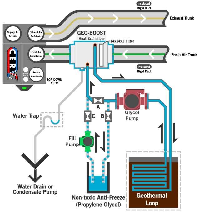
3 General Information Geo-Boost converts the CERV into a hybrid geothermal-air source heat pump, increasing both heating and cooling capacities and efficiencies. The Geo-Boost unit is connected to a geothermal loop to make use of steady ground temperatures, which allows the incoming fresh air to be either pre-heated or cooled before going to the CERV. The Geo-Boost system consists of a high efficiency, high quality heat exchanger mounted in a thermally broken (no thermal bridging) insulated housing with condensate drain outlet. The Geo-Boost interfaces with the CERV through either the CERV s hardwired auxiliary relay connection (X0), or wireless relay module. The relay controller, in conjunction with the CERV's temperature sensors, assesses Geo-Boost fresh air heating or cooling potential. Whenever Geo-Boost operation is determined to be favorable, the relay controller will activate the circulation pump (not included) to move fluid through the heat exchanger. The Geo-Boost has 8 inch diameter duct fittings, and is placed in the fresh air intake duct between the inline fresh air filter and the CERV. Half inch copper tube inlet and outlets connect to the geothermal loop. A ½ FNPT drain fitting from the condensate pan at the bottom of the heat exchange unit is connected to a drain line. A trap is required in the drain tubing in order to form a liquid seal. The drain tubing can either drain by gravity or to a condensate pump. The Geo-Boost heat exchanger unit requires no power wiring or control wiring, allowing it to be placed in the fresh air duct where most convenient. Power wire is only required for the pump and relay connection, (the wireless relay module can be mounted near the pump and/or CERV). The schematic below shows the Geo-Boost placement in the CERV's fresh air inlet and the wire connections for the relay controller. Refer to the General Geo-Loop Information section for geothermal loop layout and circulation pump selection. 3
4 Installation Schematic 4
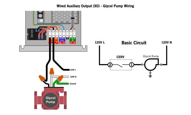
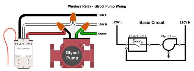
5 Installation Steps It is very important to install the unit with the proper orientation (reference above installation schematic). Markings on the Geo-Boost show the liquid inlet and outlet. The unit's air flow is indicated with a red arrow. The following is a guide for proper installation: 1) Install the Geo-Boost heat exchanger in the fresh air duct before the CERV. It must be installed in a horizontal orientation only with the condensate drain outlet on the bottom. Be sure that the unit is level to allow for proper drainage of condensation. Allow enough clearance under unit to make condensate drain connection with a proper liquid trap. All fresh air inlet ducts must be well insulated, appropriate for the climate location. Any duct areas that become moist, wet or frosted in winter require additional insulation or better sealing. 2) Connect condensate tubing to the Geo-Boost drain fitting (1/2 FNPT). The drain tubing requires a trap as shown in the schematic. A barbed fitting with flexible tubing or rigid PVC tubing can be used. If flexible tubing is used a loose knot in the tubing can suffice as the trap. Be sure that there are no kinks in the hose. Note that condensate may form during summer cooling operation, but no condensate should appear during winter operation. 3) Make connections for the geothermal pipe loop including the fill pump and charging valves as shown in the schematic. Half inch "Sharkbite" type fittings or screw clamps can be used to connect to the Geo-Boost inlet and outlet ½ copper stubs. Do not sweat fit or braze copper tubing to the Geo-Boost inlet and outlet tubes. Charge the geo-loop system and check to make sure leak free. Refer to the General Geo-Loop Information section on charging the geo-loop. 4) Make electrical connections as detailed below in the Electrical Wiring section. 5) Once Geo-Boost is installed with geo-loop fully charged and purged of air and the electrical wiring complete, power can be restored to the CERV. The CERV will begin its initial assessment upon regaining power. Continue to the next section on enabling Geo-Boost, setup and operation. Electrical Wiring Danger: risk of electric shock that can cause injury or death. Proper precautions should be used when making electrical connections. Be sure that power is off to relevant circuits while installing or servicing. The wired or wireless Geo-Boost controller gives the CERV the ability to intelligently control the Geo- Boost through one of the CERV s Auxiliary Output channels. Use appropriate wire gauge for the glycol pump. All electrical connections should be secure. If using the wireless relay, the module should be fixed in place. 5
6 6


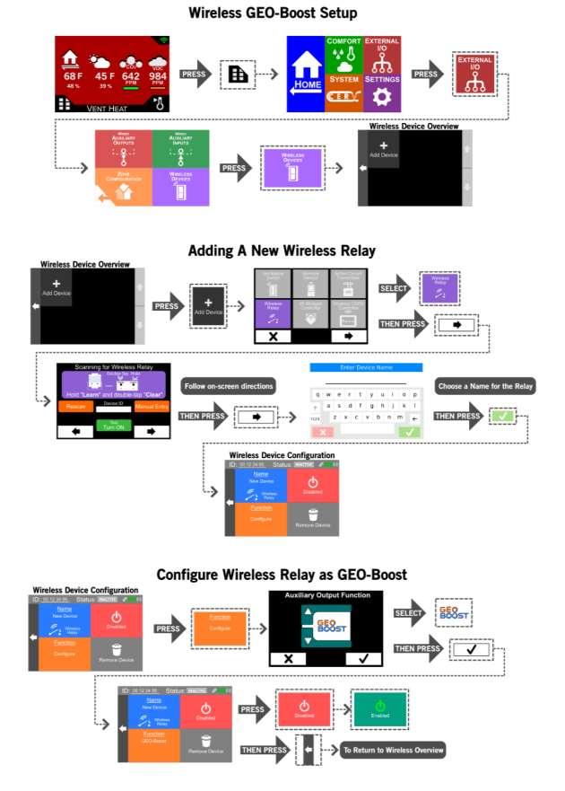
7 Geo-Boost Setup and Operation Setup Enable the Geo-Boost option on the CERV touch screen controller as shown below. The option is located in the Auxiliary Device selector. Scroll through the devices to find Geo-Boost, and press the check mark button to enable. With the Geo-Boost option enabled and the CERV completing its assessment, the Geo-Boost should activate the circulation pump for its own assessment if the CERV changes to a heating or cooling mode. The green LED on the relay controller box will be lit if the circulation pump is running. If the CERV is within set points after its assessment and is not heating or cooling, temporarily change one of the heating or cooling set points so that the CERV will begin to heat or cool. This should then start the Geo-Boost assessment to see that the pump is activating properly. The temperature set point can be changed back after verifying that the pump works. After verifying that the pump is operating correctly, set up is complete. 7
8 8
9 Operation The CERV is able to intelligently determine when the Geo-Boost provides beneficial heating or cooling to the system through the use of its internal sensors and algorithms. Through periodic assessments the CERV determines when using the Geo-Boost is beneficial or not. A Geo-Boost assessment consists of running the geothermal circulation pump at different times to determine the net effect. This is all done automatically, so there are no user inputs needed once Geo-Boost has been enabled. The CERV s mode of operation, inside and outside ambient temperatures, and ground temperature all impact whether Geo-Boost is beneficial or not. Changes in ground temperature throughout the year also have an impact on the system. There are certain conditions where assessments are not needed, so the CERV may go long periods of time without doing a Geo-Boost assessment. Geo-Boost is most likely to be beneficial during more extreme cold and warm weather periods. The Spring and Fall swing seasons will not see much of a benefit, therefore the Geo-Boost will most likely remain off. Note that because Geo- Boost pre-conditions the air to the CERV when it is being used this further offsets the air inlet temperature to the CERV from the outside ambient temperature, which is displayed on the home screen of the CERV controller. General Geo-Loop Information Geo-Loop Circulation Pumps and Pipe Loops: Circulation pumps for geo-loops are similar to those used for other hydronic systems such as solar collector fluid circulation and radiant floor heating. Grundfos UPS15-58F/FC, Grundfos Alpha, Taco OOR 3 speed pump, or similar pumps are recommended for Geo-Boost pipe loop circulation. These pumps require less than 80 Watts and will maintain a recommended flow of 1 gpm or greater. With outdoor temperatures of 0F, the Geo-Boost will add 500 to 700Watts of heating capacity to the ambient air based on geo-loop fluid delivery temperatures of 35 to 55F to the Geo-Boost heat exchanger. Installing the pump before the Geo-Boost adds part of the pump's power to the geo-loop fluid, resulting in the pump s energy transferred as heat into your home. Pipe loops should use 3/4" or 1" diameter plastic piping. Oxygen barriers are not needed in the plastic piping. "Black plastic" or PEX type plastic tubing with pipe loop lengths in the 150' to 300' range are suitable. Well-drained sandy soil requires longer tube lengths due to lower ground thermal conductivity and thermal energy capacitance while wetter soils can use shorter tube lengths. The deeper the better for burying tube to reach deep earth temperatures. The four tables below show the flow and pressure (called head ) characteristics for 3/4" and 1" diameter geo-pipe loops that are 150ft and 300ft in length. The piping pressure drop is proportional to the geo-pipe length, which allows the tables to be used for other pipe length calculations. For example, the difference between 150ft and 300ft of 3/4" pipe with 1 gpm of flow is ~0.9' H2O head ( ). That is, for each 150 of ¾ pipe at 1gpm flow 0.9 head is added. A 450' pipe loop would add 0.9'H2O plus 13.6'H2O (pressure drop for 300' of 3/4" pipe plus Geo-Boost heat exchanger) for a total of 14.5'H2O pressure drop. Most of the pressure drop occurs in the heat exchanger, so adding additional pipe length does not significantly increase pressure drop, however, pipe diameters below 3/4" rapidly increase overall system pressure drop. If smaller diameter pipe loops are desired, two or more loops could be connected in 9
10 parallel. Calculated pressure drops can be used with the pumps flow curve to find the resultant flow rate. Overall, the pump and loop sizing should result in a flow rate of ~1gpm or more. Geo-loop piping flow and pressure characteristics 3/4" & 150' Ground Loop and Heat Exchanger Flow (gpm) Head ('H2O) " & 150' Ground Loop and Heat Exchanger Flow (gpm) Head ('H2O) The amount of anti-freeze solution for charging the system depends on the length and diameter of the ground loop. Non-toxic propylene glycol is recommended for anti-freeze protection. The adjacent table provides estimates of anti-freeze volume for 3/4" to 1" pipe with 150ft to 300ft ground loop piping lengths. A 50/50 mix by volume of propylene glycol and water is recommended, premixed is fine. Pipe Loop LoopVol ID Length Volume inch ft gal Geo-loop anti-freeze charging: 3/4" & 300' Ground Loop and Heat Exchanger Flow (gpm) Head ('H2O) " & 300' Ground Loop and Heat Exchanger Flow (gpm) Head ('H2O) Adding fluid (anti-freeze and water mixture) to a geo-loop requires a charge pump that has sufficient pressure and flow capability to move air out of the loop, and to pressurize the loop slightly (~5-10 psi) above atmospheric pressure. Maintaining a loop pressure higher than atmospheric pressure keeps air from being drawn into the loop. Air in the loop can block flow, create noise, and corrode metal components in the ground loop. The ground loop piping schematic shows three valves (Valves A, B, and C) that are used to charge fluid into the loop. Valve A can be either a check valve or a ball valve (preferred) that prevents reversed flow during loop charging. Valves B and C can be "hose bib" valves that have garden hose fittings on one end of the valve. The charge pump should be a self-priming transfer pump with "hose bib" fittings such as a Simer or Wayne pump found in most big box and hardware stores. Relatively short length hoses, such as laundry hoses, can be connected to the pump's inlet and outlet fittings. The hose on the pump's outlet is connected to Valve C. The pump inlet hose should be placed in the bottom of a container holding the anti-freeze solution (eg, 5 gallon bucket). It is important that the pump inlet hose is held at the bottom of the container such that air bubbles cannot be drawn into the loop. The inlet hose to the pump should have sufficient 10
11 wall thickness and stiffness to prevent hose collapse as the pump draws fluid from the fluid charge holding container. A third hose is connected to Valve B that returns anti-freeze to the container as the loop charge pump circulates fluid through the loop. The return hose should also be kept below the surface of the anti-freeze container in order to observe when bubbles are no longer entering the container, and to keep the returning fluid from entraining air into the bucket. During the circulation process, Valve A can be opened and closed periodically which helps jar air bubbles from various locations in the loop. Note that a 1 gpm (gallon per minute) loop circulation rate requires ~10 to 15 minutes to travel through a 1" diameter, 300 ft long pipe loop. When bubbles are no longer observed returning to the container, Valve B can be slowly closed, building up pressure in the loop. Once Valve B is fully closed, Valve C can be closed and the charge pump immediately turned off. Note that the charge pump should be operating while Valve B and Valve C are closed, but that the pump should be turned off immediately after Valve C is closed. The ground loop schematic does not contain an "expansion" tank because the plastic tubing used for the ground loop has sufficient flexibility to act as its own expansion tank. In "hard pipe" systems, such as hydronic heating loops with copper pipe or "closed loop" solar hot water collector circulation systems, expansion tanks are needed in order to keep pressure variations small as water expands and contracts with temperature changes. A long plastic pipe run in a ground loop inherently has sufficient flexibility that minimizes the need for an expansion tank. 11
INSTALLATION MANUAL GEO-BOOST GROUND LOOP HEAT EXCHANGER
 1103 N HIGH CROSS RD URBANA, IL 61802 1-773-492-1893 INSTALLATION MANUAL GEO-BOOST GROUND LOOP HEAT EXCHANGER REV 1.0 The Geo-Boost system consists of the Geo-Boost heat exchanger and a relay controller
PRE-ASSEMBLED RADIANT CONTROL PANEL INSTALLATION MANUAL
 FloorHeat PRE-ASSEMBLED RADIANT CONTROL PANEL INSTALLATION MANUAL Thank you for purchasing this radiant control panel assembly. Following are some important notes that will make the installation successful.
INSTALLATION INSTRUCTIONS GEO PRIME TANK. (Patent Pending) GPC
 GPC") INSTALLATION INSTRUCTIONS GEO PRIME TANK (Patent Pending) GPC Table of Contents General Description 2 Installation 3 Flushing and Purging 5 Initial Start up 7 Adding or Checking Fluid 8 Replacing a Pump
INSTALLATION INSTRUCTIONS GEO PRIME TANK (Patent Pending) GPC Table of Contents General Description 2 Installation 3 Flushing and Purging 5 Initial Start up 7 Adding or Checking Fluid 8 Replacing a Pump
CWS Plus Sediment Filter Installation & Start Up Guide
 Clean Water Made Easy www.cleanwaterstore.com CWS Plus Sediment Filter Installation & Start Up Guide Thank you for purchasing a Clean Water System! With proper installation and a little routine maintenance
Clean Water Made Easy
 Clean Water Made Easy www.cleanwaterstore.com CWS Plus Neutralizer/Birm Blend Installation & Start-Up Guide Thank you for purchasing a Clean Water System! With proper installation and a little routine
Fleck 5600 Carbon Filter Installation & Start Up Guide
 Clean Water Made Easy www.cleanwaterstore.com Fleck 5600 Carbon Filter Installation & Start Up Guide Thank you for purchasing a Clean Water System! With proper installation and a little routine maintenance
Clean Water Made Easy
 Clean Water Made Easy www.cleanwaterstore.com CWS F5 Manual Carbon Filter Installation & Start Up Guide Thank you for purchasing a Clean Water System! With proper installation and a little routine maintenance
7800 Neutralizer Installation & Start-Up Guide
 Clean Water Made Easy www.cleanwaterstore.com 7800 Neutralizer Installation & Start-Up Guide Thank you for purchasing a Clean Water System! With proper installation and a little routine maintenance your
Clean Water Made Easy. CWS Time Clock Softener Installation & Start Up Guide. Questions?
 Clean Water Made Easy www.cleanwaterstore.com CWS Time Clock Softener Installation & Start Up Guide Thank you for purchasing a Clean Water System! With proper installation and a little routine maintenance
CERV WIRELESS TOUCHSCREEN CONTROLLER USER S MANUAL BUILD EQUINOX REVISION N. HIGH CROSS RD. URBANA, IL
 USER S MANUAL CERV WIRELESS TOUCHSCREEN CONTROLLER USER S MANUAL REVISION 1.3 BUILD EQUINOX 1103 N. HIGH CROSS RD. URBANA, IL 61802 1-773-492-1893 1 CONTROLLER OVERVIEW The CERV s wireless communication
Allcan TM Installation Manual
 Allcan TM Installation Manual NOTICE: READ THESE INSTRUCTIONS CAREFULLY. FAILURE TO FOLLOW INSTRUCTIONS VOIDS WARRANTY. Introduction: The PHP Allcan (USA patent pending) is a complete primary/secondary
INSTALLATION INSTRUCTIONS GPM SERIES LOOP PUMP MODULES
 INSTALLATION INSTRUCTIONS GPM SERIES LOOP PUMP MODULES Bard Manufacturing Company, Inc. Bryan, Ohio 43506 Since 1914...Moving, ahead just as planned. Manual: 2100-212A Supersedes: 2100-212 File: Tab 8
Clean Water Made Easy
 Clean Water Made Easy http://www.cleanwaterstore.com Pro-OX 1650 Iron Filter Installation & Start-Up Guide Thank you for purchasing a Clean Water System! With proper installation and a little routine maintenance
5700-E Sediment Filter Installation & Start-Up Guide
 Clean Water Made Easy www.cleanwaterstore.com 5700-E Sediment Filter Installation & Start-Up Guide Thank you for purchasing a Clean Water System! With proper installation and a little routine maintenance
DOUBLE O-RING GEO-PRIME TANK Non-Pressurized Flow Center System INSTALLATION INSTRUCTIONS. Model: DORGPT-1 NOTE:
 INSTALLATION INSTRUCTIONS DOUBLE O-RING GEO-PRIME TANK Non-Pressurized Flow Center System Model: DORGPT-1 NOTE: This guide provides the installer with instructions specific to the Bard Double O-Ring Geo-Prime
Fleck 2510 Sediment Filter Installation & Start-Up Guide
 Clean Water Made Easy www.cleanwaterstore.com Fleck 2510 Sediment Filter Installation & Start-Up Guide Thank you for purchasing a Clean Water System! With proper installation and a little routine maintenance
G Series. G Series Air Coils Installation ti Manual ENCASED/UNCASED AIR COILS. Geothermal/Water Source Heat Pumps R-410A Refrigerant 2-5 Ton
 G Series ENCASED/UNCASED AIR COILS Geothermal/Water Source Heat Pumps R-410A Refrigerant 2- Ton Dimensional Data G Series Air Coils Installation ti Manual Installation Information Maintenance IM1018AG1
Clean Water Made Easy
 Clean Water Made Easy http://www.cleanwaterstore.com Pro-OX 2510 Iron Filter Installation & Start- Up Guide Thank you for purchasing a Clean Water System! With proper installation and a little routine
R.A.S.E.R.S System. Installation Guide
 R.A.S.E.R.S System Installation Guide Contents R.A.S.E.R.S System components... 1 Required components for heating, cooling, and hot water...1 Provided...1 Not provided...2 Optional components...3 R.A.S.E.R.S
ECO1ZN3P, ECO2ZN4P ECO
 WARNING HOT This product may have hot fluid circulating through it. DO NOT TOUCH! SOME UNION NUTS MAY BECOME LOOSE AND CONSEQUENTLY LEAK THROUGH TRANSPORTATION VIBRATION AND HANDLING. DO NOT OVERTIGHTEN
Installation & Operation Manual Models: TSU
 TSU-I-O Rev A Installation & Operation Manual Models: TSU 150-940 CAUTION: This appliance is not intended for potable water. This manual must only be used by a qualified heating installer / service technician.
INSTALLATION & OPERATION MANUAL
 DC INVERTER AIR TO WATER HEAT PUMP AC series Heating & Cooling series CX30 INSTALLATION & OPERATION MANUAL Version 1.5 1 Table of Contents Safety Precautions... 3 Components... 4 Hydronic piping and design
INSTALLATION MANUAL CONDITIONING ENERGY RECOVERY VENTILATOR (CERV) MODEL CERV-001-PARTA, CERV-001-PARTB
 MODEL CERV-001-PARTA, CERV-001-PARTB") INSTALLATION MANUAL CONDITIONING ENERGY RECOVERY VENTILATOR (CERV) MODEL CERV-001-PARTA, CERV-001-PARTB BUILD EQUINOX SUPPORT@BUILDEQUINOX.COM (773)-492-1893 REV 0.51-06/22/2016 CONTENTS Specifications...
INSTALLATION MANUAL CONDITIONING ENERGY RECOVERY VENTILATOR (CERV) MODEL CERV-001-PARTA, CERV-001-PARTB BUILD EQUINOX SUPPORT@BUILDEQUINOX.COM (773)-492-1893 REV 0.51-06/22/2016 CONTENTS Specifications...
INSTALLATION INSTRUCTIONS TXV Coils EDM, EDD, EDA
 TXV Coils EDM, EDD, EDA These instructions must be read and understood completely before attempting installation. It is important that the Blower and Duct System be properly sized to allow the system to
Clean Water Made Easy. Fleck 7000 Tannin Filter Installation & Startup Guide. Questions?
 Clean Water Made Easy www.cleanwaterstore.com Fleck 7000 Tannin Filter Installation & Startup Guide For Tannin Filters with Vortech Distributor Screen Thank you for purchasing a Clean Water System! With
EarthLinked CC Series Compressor Unit R-410A Quik-Start Instructions
 EarthLinked CC Series Compressor Unit R-410A Quik-Start Instructions CONTENTS PAGE Pre-Installation 3 Placement & Mechanical Information 4 System Application Options 11 Desuperheater Kit 15 Anti-Freeze
Fleck 7000 Sediment Filter Installation & Start-Up Guide
 Clean Water Made Easy www.cleanwaterstore.com Fleck 7000 Sediment Filter Installation & Start-Up Guide Thank you for purchasing a Clean Water System! With proper installation and a little routine maintenance
DC INVERTER AIR TO WATER HEAT PUMP AC series Heating & Cooling series CX30
 DC INVERTER AIR TO WATER HEAT PUMP AC series Heating & Cooling series CX30 Installation and Operation Manual Version 1.7 1 Table of Contents Safety Precautions... 3 Components... 4 Hydronic piping and
INSTALLATION INSTRUCTIONS WARRANTY
 QT FLOW CENTER INSTALLATION INSTRUCTIONS Fig. 1. Low Head Pump Center Flow Chart Fig. 2. High Head Pump Center Flow Chart NOTE: Read the entire instruction manual before starting the installation. WARRANTY
Fleck 2510 SXT Catalox Installation & Start Up Guide
 Fleck 2510 SXT Catalox Installation & Start Up Guide For Catalox Filters with PotPerm Bleach Solution Tank Thank you for purchasing a Clean Water System! With proper installation and a little routine maintenance
Table of Contents. Page 2 of 28
 Rev. 1.1 Table of Contents Page Introduction 3 System Description 4 Electrical & Physical Data 5-6 Description of Electrical Controls 7-8 Chiller Controls Sequence of Operation 9 System Faults 10 Refrigeration
DC INVERTER AIR TO WATER HEAT PUMP AC series Heating & Cooling series CX45
 DC INVERTER AIR TO WATER HEAT PUMP AC series Heating & Cooling series CX45 Installation and Operation Manual Version 1 1 Table of Contents Safety Precautions... 3 Components... 4 Hydronic piping and design
Outdoor Reset Control Theory FULL versus PARTIAL reset
 Outdoor Reset Control Theory FULL versus PARTIAL reset Conventional boilers must be protected against sustained operation at low temperatures. If not, they will be damaged by sustained flue gas condensation.
INSTALLATION INSTRUCTIONS TXV Coils EBU, EBA
 TXV s EBU, EBA These instructions must be read and understood completely before attempting installation. It is important that the Blower and Duct System be properly sized to allow the system to operate
INSTALLATION INSTRUCTIONS TXV Coils EBD, EBA
 TXV Coils EBD, EBA These instructions must be read and understood completely before attempting installation. It is important that the Blower and Duct System be properly sized to allow the system to operate
EXTREME HC-2 Reverse Osmosis System
 EXTREME HC-2 Reverse Osmosis System Leader Evaporator Co., Inc. 49 Jonergin Drive Swanton, VT 05488 Tel: 802-868-5444 www.leaderevaporator.com Contents INTRODUCTION... 3 THEORY OF OPERATION... 4 Terms...
EarthLinked SCW Series Compressor Unit R-410A Quik-Start Instructions
 EarthLinked SCW Series Compressor Unit R-410A Quik-Start Instructions CONTENTS PAGE Pre-Installation 3 Placement & Mechanical Information 6 System Application Options 12 Antifreeze Protection 13 Electrical
union swing check valve spring loaded check valve purging valve pressure relief valve relief valve metered balancing valve
 VENT APPENDIX A: PIPING SYMBOL LEGEND GENERIC COMPONENTS CALEFFI COMPONENTS circulator circulator w/ ThermoBloc union circulator w/ swing check spring loaded balancing balancing w/ gate check globe s purging
General System Layout Sketch
 General System Layout Sketch EZ-37 Solar Panels PV panel Glycol Fill Valve Expansion Tank ` 1 Introduction This document describes how to install a Heliatos GH type solar water heating system. These systems
SB SERIES SE SERIES. Installation Operation Maintenance WITH BACK-UP HEAT EXCHANGER WITH BACK-UP ELECTRIC ELEMENT E113265
 E113265 Installation Operation Maintenance SB SERIES WITH BACK-UP HEAT EXCHANGER SE SERIES WITH BACK-UP ELECTRIC ELEMENT The solar energy system described in this manual, when properly installed and maintained,
OPERATING AND MAINTENANCE MANUAL
 HYDROFILL Hydronic water treatment filling units Copyright 2016 Caleffi OPERATING AND MAINTENANCE MANUAL NA10439 www.caleffi.com NA5709 series Function HYDROFILL is a water treatment fi lling unit that
Richard Hiles ClimateMaster
 Minnesota Geothermal Heat Pump Association 2012 Properly Sizing Ground Source Heat Pump Systems Richard Hiles ClimateMaster Objective Properly Size and Select GSHP System for Low Operating Costs And Proper
The electrical wattage needed by the circulator is:
 The electrical wattage needed by the circulator is: w e = 0.4344 f P n w/w A current-generation wet-rotor circulator has a maximum wire-towater efficiency in the range of 25 percent. If we put the data
EarthLinked SW Series Compressor Unit R-410A Quik-Start Instructions
 EarthLinked SW Series Compressor Unit R-410A Quik-Start Instructions CONTENTS PAGE Pre-Installation 3 Placement & Mechanical Information 4 System Application Options 10 Antifreeze Protection 14 Electrical
Aqua Balance. AquaBalance TM CONTROL MODULE QUICK START GUIDE LEGEND
 Aqua Balance AquaBalance TM CONTROL MODULE QUICK START GUIDE 10 1 Domestic Hot Water temperature setpoint decreasing button 2 Domestic Hot Water temperature setpoint increasing button 3 Central Heating
Installation, Operating, and Maintenance Manual
 www.geo-flo.com Engineered Solutions Making Geothermal Easier Installation, Operating, and Maintenance Manual Part # 3619 Rev. 27APR2017 Geo-Booster Geo-Flo Products Corporation 905 Williams Park Drive
Operation and Maintenance Haskris LX-Series, R-Series, WW-Series, OPC-Series
 Section 1: Temperature Control Your Haskris will have one of three different types of controller. Use table 1-1 to identify the relevant controller. The controller may appear different than examples. Contact
EXTREME HP-1 Reverse Osmosis System
 EXTREME HP-1 Reverse Osmosis System Leader Evaporator Co., Inc. 49 Jonergin Drive Swanton, VT 05488 Tel: 802-868-5444 www.leaderevaporator.com TABLE OF CONTENTS INTRODUCTION... 4 THEORY OF OPERATION...
EXTREME HC-4 Reverse Osmosis System Leader Evaporator Co., Inc. 49 Jonergin Drive Swanton, VT Tel:
 [Type a quote from the document or the summary of an interesting point. You can position the text box anywhere in the document. Use the Drawing Tools tab to change the formatting of the pull quote text
Install Configurations
 Table of Contents EQUIPMENT SPECS: 1 WATER SUPPLY CONFIGURATIONS 2 OPTION 1 (OPTIMIZED): BRING WATER TO MACHINES 2 OPTION 2 (ENHANCED): INSTALLING A DEDICATED WATER SOURCE 3 OPTION 3 (ENHANCED CONT.):
A. ASHRAE Handbook HVAC Applications, Snow Melting and Freeze Protection
 PAGE 238318-1 SECTION 238318 PART 1 - GENERAL 1.1 RELATED DOCUMENTS A. Drawings and general provisions of the Contract, including General and Supplementary Conditions and Division 01 Specification sections,
Bulletin (Jan 2011) And User s Guide
 And User s Guide") Bulletin 30 32 (Jan 2011) Unichiller Installation And User s Guide Customer Service If you have questions about Installation, operation and Maintenance of the Unichiller or would like to order replacement
Bulletin 30 32 (Jan 2011) Unichiller Installation And User s Guide Customer Service If you have questions about Installation, operation and Maintenance of the Unichiller or would like to order replacement
PRE-INSTALLATION GUIDE
 DENTAL VACUUM SYSTEMS PRE-INSTALLATION GUIDE for MODELS VS20 & VS40 Check VacStar Model Being Installed: VS20 VS40 Model VS20 Model VS40 Doctor: Address: Phone#: Dealer: Dealer Address: PRODUCT SPECIFICATIONS
Standard and CELDEK Evaporative Cooler Modules Installation, Operation, and Maintenance Manual
 Standard and CELDEK Evaporative Cooler Modules Installation, Operation, and Maintenance Manual Standard Evaporative Cooler CELDEK Evaporative Cooler RECEIVING AND INSPECTION Upon receiving unit, check
SOLARHOT. SuperVox. Description / Applications System Overview. Installation/ Owner s Manual
 SOLARHOT SuperVox Installation/ Owner s Manual Description / Applications System Overview The SOLARHOT SuperVox solar thermal glycol system. The SuperVox allows for easy installation of large solar water
Verde GSE PCA Bridge and Ground Mount Units 30/45/60/90/120 Tons. Installation and Maintenance Manual
 Verde GSE PCA Bridge and Ground Mount Units 30/45/60/90/120 Tons Installation and Maintenance Manual Rev. 09/17/2016 Table of Contents SAFETY... 3 GENERAL DESCRIPTION... 4 MOVING AND STORAGE... 4 INITIAL
Clean Water Made Easy
 Clean Water Made Easy http://www.cleanwaterstore.com Pro-OX 5700-E Iron Filter Installation & Start-Up Guide Thank you for purchasing a Clean Water System! With proper installation and a little routine
A hydronic system controls comfort by delivering heated or cooled fluid to the conditioned space through pipes.
 Introduction to Hydronics A hydronic system controls comfort by delivering heated or cooled fluid to the conditioned space through pipes. Hydronic heating systems use hot water or steam to deliver the
Heat Transfer Products, Inc. 120 Braley Road East Freetown, MA The first totally integrated multiple boiler management control.
 Heat Transfer Products, Inc. 120 Braley Road East Freetown, MA 02717 The first totally integrated multiple boiler management control. USING THIS MANUAL USING THIS MANUAL A. INSTALLATION SEQUENCE Follow
SEISCO APPLICATIONS & DIAGRAMS
 ALICATIONS & DIAGRS A. Seisco Selection Criteria B. Residential Floor lan Diagrams 1. Standard One Story Home Options 2. Standard Two Story Home Options 3. One Story Booster for Quicker Response C. Application
Iron Air Charge MangOx 2510 SXT Installation & Start Up Guide
 Iron Air Charge MangOx 2510 SXT Installation & Start Up Guide Thank you for purchasing a Clean Water System! With proper installation and a little routine maintenance your system will be providing iron
Multiaqua Chiller Manual
 Rev. 1.1 Multiaqua Chiller Manual The Multiaqua Chiller System is the only air conditioning/refrigeration system of its kind in the world today offering the degree of application flexibility described
EXTREME 1 Reverse Osmosis System
 EXTREME 1 Reverse Osmosis System Leader Evaporator Co., Inc. 49 Jonergin Drive Swanton, VT 05488 Tel: 802-868-5444 www.leaderevaporator.com TABLE OF CONTENTS INTRODUCTION... 4 THEORY OF OPERATION... 4
EXTREME HC-8 Reverse Osmosis System
 EXTREME HC-8 Reverse Osmosis System Leader Evaporator Co., Inc. 49 Jonergin Drive Swanton, VT 05488 Tel: 802-868-5444 www.leaderevaporator.com TABLE OF CONTENTS INTRODUCTION... 4 THEORY OF OPERATION...
PRE-INSTALLATION GUIDE
 Dry Vacuum System Part Numbers V3, V5, V7, 2V3, 2V3CT, 2V5, 2V5CT, 2V7, 3V5 and 4V5 PRE-INSTALLATION GUIDE All pumps comply with NFPA 99C level 3 requirements. All installations must conform to local codes.
Wood Boiler Plumbing Schematics
 Wood Boiler Plumbing Schematics Solo Plus Froling FHG Solo Innova Excel Multi-Fuel 2 TABLE OF CONTENTS Section Page 1.0 Introduction..4 2.0 Plumbing Diagrams....5 2.1 Plumbing Example-Solo/Excel 1........5
Installation record. Company Name: Installer Name: Address: License Number: Phone Number: Address: Installation Date Solar Loop.
 Installation record Company Name: Installer Name: Address: License Number: Phone Number: Email Address: Installation Date Solar Loop Date Pressure Solar Loop ph Service Notes USING THIS MANUAL This manual
Hydraulic Separation Moving Beyond Priamry / Secondary Piping...
 Hydraulic Separation Moving Beyond Priamry / Secondary Piping... load! #1 load! #2 load! #3 primary! circulator presented by: John Siegenthaler, P.E. Appropriate Designs Holland Patent, NY www.hydronicpros.com
HPS Controls Ltd. Series 600 LFI / CFI Series 700 HFS Zone Control Stations. Heating and Radiant Floor Zone Control Stations
 Series 600 LFI / CFI Series 700 HFS Zone Control Stations Heating and Radiant Floor Zone Control Stations Installation Instructions Thank you for purchasing the finest in heating and radiant floor Control
Aprilaire Dehumidifier Troubleshooting Manual Models 1830 & 1850
 Aprilaire Dehumidifier Troubleshooting Manual Models 1830 & 1850 Table of Contents Troubleshooting Diagnostic Codes... 2 E1, E2... 2 E3, E4... 3 E5, E6 & E7... 7 E8... 8 E9 9 Verifying Capacity... 10 Water
CHILLER. Operator s & Installation Manual
 CHILLER MODEL: CFF-500 Operator s & Installation Manual Release Date: November 3, 1996 Publication Number: 90667 Revision Date: May 10, 2010 Revision: E Visit the IMI Cornelius web site at www.cornelius.com
CONTENTS CONSIDERATIONS. General Plumbing Component Connection ILLUSTRATION. Control System CONFIGURATION. Voltage Verification CONNECTION
 AIR SERIES SYSTEM INSTALLATION MANUAL CONTENTS CONSIDERATIONS General Plumbing Component Connection 2 2 2 ILLUSTRATION Control System 3 CONFIGURATION Voltage Verification 4 CONNECTION Component Connection
DLCLRA. INSTALLATION INSTRUCTIONS Outdoor Unit Single Zone Ductless System Sizes 36 to 58 TABLE OF CONTENTS
 DLCLRA INSTALLATION INSTRUCTIONS Outdoor Unit Single Zone Ductless System Sizes 36 to 58 Fig. 1 - Size 36 TABLE OF CONTENTS PAGE SAFETY CONSIDERATIONS... 2 PARTS LIST... 3 SYSTEM REQUIREMENTS... 4 WIRING...
... Green Building Details
 Combining Solar HW with Radiant Floor using a Demand Water Heater back-up and a Tempering Tank with a line voltage three-way valve to prevent heating the solar storage with the gas DHW... A short list
2.A MANIFOLD SHUNTS MINI SHUNTS
 2.A MANIFOLD SHUNTS MINI SHUNTS ROTH HEATING SYSTEMS 2A. MANIFOLD SHUNTS Roth Manifold Shunts 4"/5.8cv and 1"/7.0cv Preassembled, manually adjusted, proportional temperature mixing station with built-in,
INSTALLATION INSTRUCTIONS
 INSTALLATION INSTRUCTIONS GVDM-26 DOMESTIC HOT WATER DESUPERHEATER PUMP MODULE KIT BMC, Inc. Bryan, Ohio 43506 Manual: 2100-546C Supersedes: 2100-546B Date: 4-18-16 Page 1 of 11 CONTENTS General... 3 Description...
Selecting Circulators TD10 EFFECTIVE: SUPERSEDES:
 TACO COMFORT SOLUTIONS : HOME HEATING BASICS Selecting Circulators TD EFFECTIVE:.3. SUPERSEDES:.. This article shows you how to select a Taco circulator that lets the hydronic system you re designing perform
1 Exam Prep Solar Water and Pool Heating Manual (UCF) Questions and Answers (Plumbing Contractor)
 Questions and Answers (Plumbing Contractor)") 1 Exam Prep Solar Water and Pool Heating Manual (UCF) Questions and Answers (Plumbing Contractor) 1. For year-round use, a collector tilt of degrees works best for a project located in Tampa, Florida.
1 Exam Prep Solar Water and Pool Heating Manual (UCF) Questions and Answers (Plumbing Contractor) 1. For year-round use, a collector tilt of degrees works best for a project located in Tampa, Florida.
Table of Contents. Installation, Operation, and Maintenance Manual V100 Series
 V101 EXPANSION TANK CONNECTION WARRANTY ON PUMPS VOID IF RUN DRY! CHECK VALVES INSTALLED IN ALL PUMPS WARNING HOT This product may have hot fluid circulating through it. DO NOT TOUCH! V10 EXPANSION TANK
APPLICATION DATA SHEET
 APPLICATION DATA SHEET General Piping Recommendations and Refrigerant Line Length for Split-System Air Conditioners and Heat Pumps GENERAL GUIDELINES This Split-System (Air Conditioning Condensing/Heat
KITS COMMON TO HEATING AND COOLING EQUIPMENT 504,652M 03/04. Supersedes 503,249M
 2004 Lennox Industries Inc. Dallas, Texas KITS COMMON TO HEATING AND COOLING EQUIPMENT 504,652M 03/04 Supersedes 503,249M Litho U.S.A. COMPRESSOR REPLACEMENT KIT INSTALLATION INSTRUCTIONS FOR COMPRESSOR
Installation Instructions
 38MHR Outdoor Unit Single Zone Ductless System Sizes 09 to 24 Installation Instructions NOTE: Read the entire instruction manual before starting the installation. NOTE: Images are for illustration purposes
INSTALLATION INSTRUCTIONS & HOME OWNERS MANUAL AUTOBOOSTER IMPORTANT SAFETY INFORMATION
 INSTALLATION INSTRUCTIONS & HOME OWNERS MANUAL AUTOBOOSTER IMPORTANT SAFETY INFORMATION When installing or using any high voltage electrical appliance, basic safety precautions should always be followed.
EarthLinked HC Series Compressor Unit R-410A Quik-Start Instructions
 EarthLinked HC Series Compressor Unit R-410A Quik-Start Instructions CONTENTS PAGE Pre-Installation 3 Placement & Mechanical Information 4 System Application Options 11 Antifreeze Protection 14 Electrical
EarthLinked SC Series Compressor Unit R-407C Quik-Start Instructions
 EarthLinked SC Series Compressor Unit R-407C Quik-Start Instructions CONTENTS PAGE Pre-Installation 3 Placement & Mechanical Information 4 System Application Options 11 Desuperheater Kit 15 Antifreeze
EARTHLINKED GEOTHERMAL RENEWABLE ENERGY SYSTEMS MAINTENANCE GUIDE
 EARTHLINKED GEOTHERMAL RENEWABLE ENERGY SYSTEMS MAINTENANCE GUIDE This guide is directed at EarthLinked trained and authorized technicians servicing and maintaining the system and should be left with the
Solar Water Heaters. Bastián Acevedo Bustos. Electronic Engineering Student, Tarapacá University. Environmental Studies Student, York University
 Solar Water Heaters Bastián Acevedo Bustos Electronic Engineering Student, Tarapacá University Environmental Studies Student, York University Systems Active System Active systems use one or more pumps
DC INVERTER AIR TO WATER HEAT PUMP
 DC INVERTER AIR TO WATER HEAT PUMP Installation and Operation Manual CX34 Options for Heating, Cooling and Domestic Hot Water Version 1.4 1 Table of Contents Safety Precautions... 3 CX34 components...
Daikin Water Cooling, Heating, and High Capacity Booster Coils
 Installation and Maintenance Manual IM 900 Daikin Water Cooling, Heating, and High Capacity Booster Coils Group: Applied Air Part Number: IM 900 Date: February 2008 Types HI-F5, E-F5 2008 Daikin International
KODIAK RECIRCULATING CHILLERS TECHNICAL MANUAL RC006, RC009, RC011, RC022, RC030 and RC045 G03, H03 and J03 Series
 KODIAK RECIRCULATING CHILLERS TECHNICAL MANUAL RC006, RC009, RC011, RC022, RC030 and RC045 G03, H03 and J03 Series Lytron Inc., 55 Dragon Court, Woburn, MA 01801, USA Tel: +1-781-933-7305 Fax: +1-781-935-4529
ASTRO 2 SERIES HOT WATER RE-CIRCULATION SYSTEM INSTALLATION AND OPERATING INSTRUCTIONS
 ASTRO SERIES HOT WATER RE-CIRCULATION SYSTEM INSTALLATION AND OPERATING INSTRUCTIONS File No: 10.81 Date: july 11, 018 Supersedes: 10.81 Date: february 4, 017 1.0 Typical application 1.0 How it works 1
Installation, Operating and Servicing Instructions
 ENGLISH 0 / 0 / 0 / 0 / 00 Installation, Operating and Servicing Instructions FRANCAIS NEDERLANDS ESPAÑOL Y000.A EN ESPAÑOL NEDERLANDS FRANCAIS ENGLISH INDEX WARNING Who should read these instructions
PACKAGED AIR COOLED Product Data Catalog
 PACKAGED AIR COOLED Product Data Catalog MODELS ASP-10A ASP-15A ASP-20A ASP-00P ASP-00F ASP-00G A MEMBER OF MARDUK HOLDING COMPANY, LLC The Leader in Modular Chillers ETL and CSA Approved CHILLER MODULES
Pipe: ASTM B88, hard drawn copper, Type K. Fittings: ASTM B16.22 Wrought copper and copper alloy.
 Design Standard Hydronic Piping in Buildings Detailed specifications follow. PART 1 - GENERAL 1.01 Above ground hydronic piping 2 inches and less in diameter shall be as follows: Copper PEX-A Pipe: ASTM
Standard and CELDEK Evaporative Cooler Modules Installation, Operation, and Maintenance Manual
 Standard and CELDEK Evaporative Cooler Modules Installation, Operation, and Maintenance Manual Standard Evaporative Cooler CELDEK Evaporative Cooler RECEIVING AND INSPECTION Upon receiving unit, check
Table of Contents. Installation, Operation, and Maintenance Manual ELBPxx
 Series ELBP8/ELBP30 FUSE C 4Vac R NC NO 0 min 5 Delay Off Actuator GROUND NEUTRAL LIVE Reset R CAUTION 5 VOLTS ONLY 3 4 5 6 7 8 8 Zone Wired Module 4038 Dry Contacts Pump Boiler ELBP50 GROUND NEUTRAL Reset
PCAH SERIES AIR HANDLER
 PCAH SERIES AIR HANDLER PCAH2/PCAH3/PCAH4 OPERATING MANUAL 1 2 3 4 5 6 7 8 9 10 TABLE OF CONTENTS GETTING STARTED... 3 ELECTRICAL CONNECTIONS... 3 2.1 POWER CONNECTIONS... 3 2.1.1 PCAH2/PCAH3... 3 2.1.2
CELDEK Evaporative Cooler Module Installation, Operation, and Maintenance Manual. CELDEK Evaporative Cooler
 CELDEK Evaporative Cooler Module Installation, Operation, and Maintenance Manual CELDEK Evaporative Cooler RECEIVING AND INSPECTION Upon receiving unit, check for any interior and exterior damage, and
"Best Practices in Modern Hydronic Heating - THE DETAILS
 "Best Practices in Modern Hydronic Heating - THE DETAILS 190 supply water temperature (ºF) 170 150 130 110 90 fin-tube convector (RR=1.38) panel radiator (RR=1.0) thin slab rad. floor (RR=0.69) slab r
PRE-INSTALLATION GUIDE
 DENTAL VACUUM SYSTEMS PRE-INSTALLATION GUIDE for MODELS VS50, VS50H, VS80 & VS80H Model VS50 Model VS50H Model VS80 Model VS80H This VacStar Model is being installed: (AS CHECKED) VS50 VS80 VS50H VS80H