INSTALLATION MANUAL CONDITIONING ENERGY RECOVERY VENTILATOR (CERV) MODEL CERV-001-PARTA, CERV-001-PARTB
|
|
|
- Bennett Lamb
- 5 years ago
- Views:
Transcription


1 INSTALLATION MANUAL CONDITIONING ENERGY RECOVERY VENTILATOR (CERV) MODEL CERV-001-PARTA, CERV-001-PARTB BUILD EQUINOX (773) REV /22/2016
2
3 CONTENTS Specifications... 4 CERV System Footprint... 4 Nameplate Ratings... 4 General Considerations... 5 Installation Procedure... 6 Ducting The Units Together... 6 Filters... 8 Insulating... 9 Water Drain Electrical General Wiring Guidelines Electrical Installation Auxiliary Heater Option Wireless Ventilation Switch Option Starting and Commissioning the System Wireless TouchScreen Controller Heat Pump Operation ECM Fan Speed Configuration Appendix - Electrical... 20


4 SPECIFICATIONS CERV SYSTEM FOOTPRINT NAMEPLATE RATINGS Revision 1.51 [06/22/2016] Page 4
5 GENERAL CONSIDERATIONS DANGER: RISK OF ELECTRIC SHOCK. CAN CAUSE INJURY OR DEATH: DISCONNECT ALL REMOTE ELECTRIC POWER SUPPLIES BEFORE SERVICING. 1. Please review entire manual before proceeding with installation. Improper installation or deviation from instructions can result in damage and warranty being voided. 2. Ensure that all components are on hand and free from defects or damage. Base CERV system consists of Part-A, Part-B, (2) inline fans, touchscreen controller, and touchscreen power supply. Review invoice for any additional options that may have been ordered. 3. Installation should be performed by qualified personnel with a thorough understanding of electrical safety precautions. Units must be properly grounded. 4. Beware of sharp edges when assembling duct connections and do not lift modules by duct fittings. 5. Units should be secure and level. If installing on a platform, ensure levelness and structural stability of the platform. 6. Fresh air inlet and exhaust outlet ducts to house from outside: a. Must be sufficiently above ground to avoid blockage from snow or other obstructions. Two feet above ground is recommended. b. Ducts to the outside must use a coarse screen or mesh to prevent insects, birds, etc from entering, but fine screens, dampers, flaps, etc should be removed so as to eliminate any restrictions. c. If possible both inlet and exhaust should be on same side of house to avoid pressure differential, which can impact flow. d. Inlet and exit ducts should be a minimum of 4 apart in any orientation. Inlet separation from any other possible sources of contamination should be considered and local codes followed. 7. Ducts must be insulated as directed in ducting section. Improper or insufficient duct insulating can lead to condensation and staining and/or water damage. 8. Water drain must be lower than the drain outlet from the CERV-001-PARTA module. If not, a condensate pump must be used. 9. An inline water trap must be effectively utilized as detailed later to prevent air from being drawn into the CERV-001-PARTA unit through the drain tubing. Revision 1.51 [06/22/2016] Page 5

 can be placed under CERV to reduce vibration and to keep CERV off of a potentially wet floor surface. 4.")
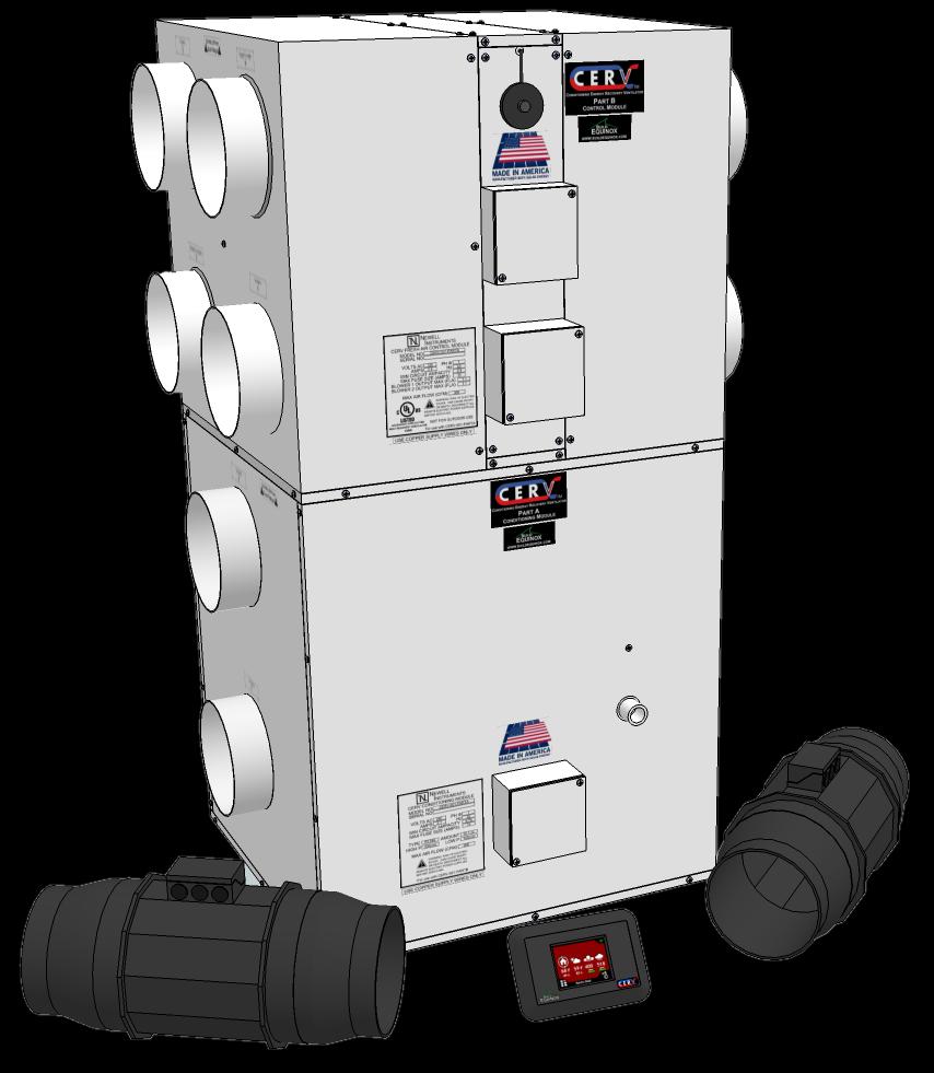
6 INSTALLATION PROCEDURE 1. Review Ducting section below to determine most applicable ducting scheme. The two modules Part A and Part B can be stacked vertically (most common) or set horizontally. 2. It is recommended to install the CERV-001-PARTA in a plastic appliance basin if location is such that water damage is a concern. A clogged condensate line can cause water to pool around CERV. A moisture sensor and alarm can also be used to notify occupant of a problem. 3. Fix CERV-001-PARTA and CERV-001-PARTB modules into position and ensure stability. Units must be level. Vibration feet (not provided) can be placed under CERV to reduce vibration and to keep CERV off of a potentially wet floor surface. 4. Determine locations for the blowers to inside and to outside (and if applicable, auxiliary heater) and filer boxes. Blowers should always be drawing air through the CERV, and blowing air to the supply/exhaust ducting. Mount blowers in position and ensure stability. DUCTING THE UNITS TOGETHER For ducting the PARTA and PARTB units together, rigid (galvanized) duct fittings should be used. All ducting between the units must be insulated and sealed, especially the outlet side, since the air will be heated or cooled (depending on the duct) and could cause condensation on the ducts. Revision 1.51 [06/22/2016] Page 6

7 Due to the flexible nature of the system, there are several ways to duct the CERV for operation. See the following to determine the most applicable configuration. Revision 1.51 [06/22/2016] Page 7


8 FILTERS A filter must be installed in line with the system, so that the fresh air is filtered before it enters the CERV. Additionally, you may wish to filter the return air to remove dust or other particulates from the air when the CERV is in a recirculation mode. Both configurations are shown below. Build Equinox offers two inline filter options for sale. An Insulated Filter Box that is suitable for filtering fresh air while preventing condensation and an Uninsulated filter box for the return air. The filter boxes use a standard 10 x 20 x 1 filter, allowing you to choose a filter level that suits your needs. Revision 1.51 [06/22/2016] Page 8
9 INSULATING In the winter, the unit will be bringing in cold air, passing it through the heat pump, and then exhausting EVEN COLDER air. In the summer, the CERV will be bringing in hot air, passing through the heat pump, and exhausting EVEN HOTTER air. It is therefore extremely important that the components of the system are properly insulated, as to prevent any condensation on the ducting. PART A AND PART B MODULES The Part A (control module) and Part B (heat pump module) are internally insulated using a UL approved R8.0 insulation. The Part A and Part B modules therefore do not need to be insulated (with the exception of the duct fittings). DUCTS All ducts except for the RETURN (from inside) must be insulated. It is recommended to use a minimum of R6.0 insulation (such as 6 fiberglass ductwork insulation sleeve found at home improvement stores). In colder climates, it may be necessary to add additional insulation if it appears that the ducts may be showing signs of sweating. FILTER BOXES The Fantech FB6 filter box, if used in the fresh air supply line, must be insulated. If the Insulated Filter Box was purchased, no additional filter insulation is needed. It is recommended to use a minimum of R6.0 insulation surrounding the entire filter box (be sure to leave a way to replace the filter). If there are multiple filter boxes stacked together (such as one on top of the other), you must insulate between the two. IN-LINE FANS Both supply and exhaust fans must be insulated. It is recommended to use a minimum of R6.0 insulation surrounding each fan. If there are multiple fans stacked together (such as one on top of the other), you must insulate between the two with a double layer of insulation. In the winter, for instance, the supply fan may be blowing 80F air inside the house, while the exhaust fan may be blowing 30F air back outside. Without insulation between the two fans, therefore, the CERV s conditioning capabilities would be severely diminished. Revision 1.51 [06/22/2016] Page 9

10 WATER DRAIN 1. Part A has a 3/4 PVC condensate drain outlet, which must be connected. 2. It is imperative to create a water trap in the drain tube to prevent air flow through the condensate line which will inhibit proper condensate flow. It is recommended to use the EZ Trap sold by Build Equinox. This clear trap allows the water seal to be seen and also has clean out ports for easy maintenance. 3. After the water trap the drain line after can simply be run to a floor or other drain as long as it is below the trap level, otherwise a condensate pump must be used. Revision 1.51 [06/22/2016] Page 10


11 ELECTRICAL DANGER: RISK OF ELECTRIC SHOCK. CAN CAUSE INJURY OR DEATH: DISCONNECT ALL REMOTE ELECTRIC POWER SUPPLIES BEFORE SERVICING. Electrical Ratings CERV-001-PARTA CERV-001-PARTB Volts AC 120 Volts AC 120 Amps 4.2 Amps 2.5 Ph Ф 1 Ph Ф 1 Hz 60 Hz 60 Minimum Circuit Ampacity 8.75 Minimum Circuit Ampacity 2.5 Max Fuse Size (Amps) 15 Max Fuse Size (Amps) 15 Blower 1 Output Max (Fla) 1.1 Blower 2 Output Max (Fla) 1.1 GENERAL WIRING GUIDELINES All electrical wiring should be performed as to comply with National Electric Code NFPA 70. Additionally, be aware of any additional city or utility code requirements before installation. Units must be properly grounded. System power to CERV-001-PARTA and PARTB must comply with the nameplate requirements. The CERV should have its own dedicated circuit if possible. Never run control wiring and power wiring through the same conduit. Always use proper gauge stranded copper wire for power connections. ELECTRICAL INSTALLATION 1. For further electrical information, see the Appendix at the end of the document. 2. MAKE SURE THE CIRCUIT IS NOT HOT, i.e. breaker switch is off or fuse is out. Revision 1.51 [06/22/2016] Page 11
 to the CERV-001-PARTB module.")
12 3. Run electrical supply (120vAC) to the CERV-001-PARTA module. The power input from your supply panel connects to the 16 gauge White and Black wires in the junction box on the module. Ground the power input with the included green ground screw. 4. Run electrical supply (120vAC) to the CERV-001-PARTB module. The power input from your supply panel connects to the 16 gauge White and Black wires labeled 120vN and 120vH in the high voltage junction box on the module. Ground the power input with the included green ground screw. 5. Part A and Part B can be powered from the same 120vAC source. 6. It is recommended to place a switch in the same area as the CERV to shut power off to the unit when needed. Revision 1.51 [06/22/2016] Page 12
 and neutral (white) in the HV junction box.")
13 7. The CERV s external in-line fans are powered directly from the CERV. Run wire to the blowers from the CERV-001-PARTB high voltage junction box. Each blower is powered individually, so ensure that the correct blower is wired to its corresponding wires labeled hot (red) and neutral (white) in the HV junction box. The supply blower wires will be labeled BinN and BinH, while the exhaust blower wires will be labeled BoutN and BoutH. Blowers may share the same ground (green). Revision 1.51 [06/22/2016] Page 13


14 8. Run the included 4 wire low voltage cable from PARTA to PARTB. Connect the Black wire to terminal F+, Red to F-, White to FR, and Green to FT. Low voltage wiring does not need to be inside conduit, just ensure that it is secure. See figure below. 9. Remove and discard the small green circuit board from the +10V, 0-10V, and GND terminals from each of the CERV s two in-line ECM fans. Revision 1.51 [06/22/2016] Page 14

15 10. Run two conductor low voltage cable (not included, minimum 24ga) from PARTB Low Voltage Box to the supply and exhaust fans. These cables are used to control the speed of each fan. Connect the BIN PWM terminal from PARTB to the 0-10V terminal on the supply blower. Connect the BOUT PWM terminal from PARTB to the 0-10V terminal on the exhaust blower. Connect the F + terminal from PARTB to the GND GND terminals of both supply and exhaust blowers. See figure below. Revision 1.51 [06/22/2016] Page 15
.")

16 11. Auxiliary Heater Option (If not used, skip to next step) a. Run control wiring from the LV junction box of PART B to the aux heater (the yellow and black wires included with the heater). This wire will only carry a low current 24vAC control signal; Thermostat wire may be acceptable if the included wire is not long enough. b. Set the Warm Air dial, pictured below, to a value of 7 and install the included temperature sensor in the duct after the auxiliary heater. c. Follow electrical wiring procedures for installation of supply line power to auxiliary heater. Revision 1.51 [06/22/2016] Page 16

17 12. Wireless Ventilation Switch Option (If not used, skip to next step) a. Follow the wiring diagram below and match the colors of the wires to the terminal block labels. b. Wires may be run through the same stress relief as the PARTA wiring, and the wireless relay can be secured with a strip of Velcro (not included). c. A short length of adhesive backed Hook and Loop fastener is included with the wireless switch relay. This may be used to mount the relay near the junction box. Ensure that you still have access to the Clear and Learn buttons on the relay. Revision 1.51 [06/22/2016] Page 17
18 STARTING AND COMMISSIONING THE SYSTEM Please review all ducting, insulating, condensate drain, and electrical sections before continuing. After all electrical wiring has been completed and all connections have been double checked, apply power to the unit. If the blowers turn on, everything is working properly, if not, go back and check all wiring again. When the unit is first started, it will turn on the inside blower for approximately 10 seconds before starting up the rest of the system. Use this to ensure that the blowers are correctly wired (i.e. BIN wires go to the supply blower, BOUT wires go to the exhaust blower). For the first 3 minutes after startup, the CERV will go into an Assess mode. In this mode, it recirculates air throughout the home and compares to the configured heating, cooling, and ventilation setpoints. For commissioning the unit, it is important to check the following features of the unit: WIRELESS TOUCH SCREEN CONTROLLER Locate the touch screen controller and its power supply. For commissioning purposes, the touchscreen controller should be brought into the same room as the CERV. 1. Plug the power supply into the touchscreen controller and then plug the power supply into an outlet. 2. The CERV logo will initially show on the screen, and then after 5 seconds, you will enter the home screen. This screen displays the inside and outside temperature and relative humidity, as well as the CO2 and VOC indoor air quality levels. 3. In the top right corner of the home screen, there is a small wireless connectivity icon. Within about 10 seconds, the icon should be green. If the icon stays gray with a red X, there may be a communication problem. Check power to the CERV and compare the serial number on back of the touchscreen with the serial number on CERV Part B to ensure they match. If this is unable to be resolved, please contact Build Equinox at (773) Once the wireless connectivity icon turns green, the touchscreen controller and the CERV have successfully communicated. You may proceed to the next section. HEAT PUMP OPERATION In this section, we will ensure that the heat pump has been wired correctly and is operating. 1. With the CERV and Wireless Touchscreen powered and communicating, enter the Temperature Setpoint screen by pressing the icon at the bottom of the right of the home screen: 2. The goal is to force the heat pump to enable, so adjust the setpoints so that the CERV is either heating, or cooling. That is, if it is 70 degrees inside and you want to force it to cool, you could select a cooling setpoint of 65 and a heating setpoint of 60. Or to force it to heat, you could set the cooling setpoint to 80 and heating setpoint to If the CERV was previously off (because no conditioning was needed), it will perform another 3 minute assessment period and then begin to heat or cool. If the CERV was active, it should immediately start heating or cooling. Press the check box in the setpoints screen to accept the changes. Revision 1.51 [06/22/2016] Page 18
19 4. The touchscreen should shortly update and show the new mode. Compressor operation can be verified by the following: a. If the room is quiet enough, you may be able to hear the compressor start b. With a clamp-on ammeter, you can test the current flowing through the 120v power wires to the compressor. Normal compressor operation can be anywhere around 2-4 amps, depending on the conditions. c. You may be able to feel the supply air getting warm or cold, depending on the mode. d. After around 5 minutes of operation, if the compressor still has not come on, the touchscreen controller will display an alert in the top right corner of the home screen. When you tap the icon, it will take you to the alerts screen, which will display more information. ECM FAN SPEED CONFIGURATION The fan speed has been factory set to 80%. If airflow measurements are being taken for commissioning purposes the fan speed can be increased or decreased by following the steps in the Touchscreen User s Manual. Revision 1.51 [06/22/2016] Page 19
20 APPENDIX - ELECTRICAL DANGER: RISK OF ELECTRIC SHOCK. CAN CAUSE INJURY OR DEATH: DISCONNECT ALL REMOTE ELECTRIC POWER SUPPLIES BEFORE SERVICING. ELECTRICAL CONNECTIONS QUICK REFERENCE GUIDE CERV-001-PARTA - Conduit Box High Voltage Connections: 120 H (Black): Connect to 120V POWER SUPPLY BLACK wire. 120 N (White): Connect to 120V POWER SUPPLY WHITE wire. Ground Screw: Connect to 120V POWER SUPPLY GROUND wire (green). CERV-001-PARTA - Conduit Box Low Voltage Cable BLACK Wire: Connect to F+ SCREW TERMINAL of CERV-001-PARTB LOW VOLTAGE CONDUIT BOX. RED Wire: Connect to F- SCREW TERMINAL of CERV-001-PARTB LOW VOLTAGE CONDUIT BOX. WHITE Wire: Connect to FR SCREW TERMINAL of CERV-001-PARTB LOW VOLTAGE CONDUIT BOX GREEN Wire: Connect to FT SCREW TERMINAL of CERV-001-PARTB LOW VOLTAGE CONDUIT BOX CERV-001-PARTB - High Voltage Conduit Box: 120 H (Black): Connect to 120V POWER SUPPLY HOT wire (black). 120 N (White): Connect to 120V POWER SUPPLY NEUTRAL wire (white). Bin H (Red): Connect to SUPPLY BLOWER HOT wire (black). Bin N (white): Connect to SUPPLY BLOWER NEUTRAL wire (white). Bout H (Red): Connect to EXHAUST BLOWER HOT wire (black). Bout N (white): Connect to EXHAUST BLOWER NEUTRAL wire (white). Ground Screw (green): Connect ground wires from 120V POWER SUPPLY, SUPPLY BLOWER, and EXHAUST BLOWER with green ground screw. CERV-001-PARTB - Low Voltage Conduit Box: F+: Connect to CERV-001-PARTA LOW VOLTAGE cable BLACK WIRE, SUPPLY BLOWER GND TERMINAL, EXHAUST BLOWER GND TERMINAL F-: Connect to CERV-001-PARTA LOW VOLTAGE cable RED WIRE. FR: Connect to CERV-001-PARTA LOW VOLTAGE cable WHITE WIRE. FT: Connect to CERV-001-PARTA LOW VOLTAGE cable GREEN WIRE. BIN PWM: Connect to SUPPLY BLOWER 0-10V TERMINAL BOUT PWM: Connect to EXHAUST BLOWER 0-10V TERMINAL B: (Wireless Switch Option) Black wire from wireless relay DLC. Y: (Wireless Switch Option) Yellow wire from wireless relay DLC. R&G: (Wireless Switch Option) Red and Gray (or white) wires from wireless relay DLC. N: (Auxiliary Device Option) Connect 24v control wire to auxiliary device (24V Neutral). H: (Auxiliary Device Option) Connect 24v control wire to auxiliary device (24V Hot). Supply Blower Conduit Box: (EARTH GROUND): Connect to CERV-001-PARTB GROUND SCREW H: Connect to CERV-001-PARTB BIN H (Red) L: Connect to CERV-001-PARTB BIN N (White) 0-10V: Connect to CERV-001-PARTB BIN PWM TERMINAL GND: Connect to CERV-001-PARTB F+ GND TERMINAL Exhaust Blower Conduit Box: (EARTH GROUND): Connect to CERV-001-PARTB GROUND SCREW H: Connect to CERV-001-PARTB BOUT H (Red) L: Connect to CERV-001-PARTB BOUT N (White) 0-10V: Connect to CERV-001-PARTB BOUT PWM TERMINAL GND: Connect to CERV-001-PARTB F+ GND TERMINAL Revision 1.51 [06/22/2016] Page 20
21 NOTES
22 NOTES
23 1103 N. High Cross Rd. Urbana, IL (773) Build Equinox 2016 All Rights Reserved
OPERATION GUIDE MODEL CERV-001-PARTA, CERV-001-PARTB CONDITIONING ENERGY RECOVERY VENTILATOR (CERV)
") OPERATION GUIDE MODEL CERV-001-PARTA, CERV-001-PARTB CONDITIONING ENERGY RECOVERY VENTILATOR (CERV) BUILD EQUINOX SUPPORT@BUILDEQUINOX.COM (773)-492-1893 REV 0.50-06/16/2016 Contents Overview... 4 CERV
OPERATION GUIDE MODEL CERV-001-PARTA, CERV-001-PARTB CONDITIONING ENERGY RECOVERY VENTILATOR (CERV) BUILD EQUINOX SUPPORT@BUILDEQUINOX.COM (773)-492-1893 REV 0.50-06/16/2016 Contents Overview... 4 CERV
Standard and CELDEK Evaporative Cooler Modules Installation, Operation, and Maintenance Manual
 Standard and CELDEK Evaporative Cooler Modules Installation, Operation, and Maintenance Manual Standard Evaporative Cooler CELDEK Evaporative Cooler RECEIVING AND INSPECTION Upon receiving unit, check
Standard and CELDEK Evaporative Cooler Modules Installation, Operation, and Maintenance Manual
 Standard and CELDEK Evaporative Cooler Modules Installation, Operation, and Maintenance Manual Standard Evaporative Cooler CELDEK Evaporative Cooler RECEIVING AND INSPECTION Upon receiving unit, check
INSTALLATION MANUAL GEO-BOOST GROUND LOOP HEAT EXCHANGER
 1103 N HIGH CROSS RD URBANA, IL 61802 1-773-492-1893 INSTALLATION MANUAL GEO-BOOST GROUND LOOP HEAT EXCHANGER REV 1.0 The Geo-Boost system consists of the Geo-Boost heat exchanger and a relay controller
CELDEK Evaporative Cooler Module Installation, Operation, and Maintenance Manual. CELDEK Evaporative Cooler
 CELDEK Evaporative Cooler Module Installation, Operation, and Maintenance Manual CELDEK Evaporative Cooler RECEIVING AND INSPECTION Upon receiving unit, check for any interior and exterior damage, and
RV Products Division INSTALLATION INSTRUCTIONS FOR SERIES PACKAGE AIR CONDITIONER
 RV Products Division INSTALLATION INSTRUCTIONS FOR 46413 SERIES PACKAGE AIR CONDITIONER 1. WARNINGS IMPORTANT NOTICE These instructions are for the use of qualified individuals specially trained and experienced
INSTALLATION INSTRUCTIONS FOR 8330*63**, 8530*63** CHILLGRILLE FLUSH MOUNT CEILING ASSEMBLY
 RV Products Division INSTALLATION INSTRUCTIONS FOR 8330*63**, 8530*63** CHILLGRILLE FLUSH MOUNT CEILING ASSEMBLY DESIGNED AND MANUFACTURED BY THE MAKERS OF COLEMAN -MACH AIR CONDITIONERS TABLE OF CONTENTS
INSTALLATION INSTRUCTIONS FOR 8330*633* COOL ONLY A/C 8330*635* HEAT READY A/C 8530*63** HEAT PUMP CHILLGRILLE FLUSH MOUNT CEILING ASSEMBLY
 RV Products Division INSTALLATION INSTRUCTIONS FOR 8330*633* COOL ONLY A/C 8330*635* HEAT READY A/C 8530*63** HEAT PUMP CHILLGRILLE FLUSH MOUNT CEILING ASSEMBLY DESIGNED AND MANUFACTURED BY THE MAKERS
OPERATION GUIDE MODEL CERV-001-PARTA, CERV-001-PARTB CONDITIONING ENERGY RECOVERY VENTILATOR (CERV)
") OPERATION GUIDE MODEL CERV-001-PARTA, CERV-001-PARTB CONDITIONING ENERGY RECOVERY VENTILATOR (CERV) OPERATION GUIDE OVERVIEW Managing a home's air quality is a demanding job. Between the resident's preferences,
OPERATION GUIDE MODEL CERV-001-PARTA, CERV-001-PARTB CONDITIONING ENERGY RECOVERY VENTILATOR (CERV) OPERATION GUIDE OVERVIEW Managing a home's air quality is a demanding job. Between the resident's preferences,
INSTALLATION INSTRUCTIONS FOR 6532 SERIES PACKAGE HEAT PUMP
 INSTALLATION INSTRUCTIONS FOR 6532 SERIES PACKAGE HEAT PUMP RV Products A Division of Airxcel, Inc. P.O. Box 4020 Wichita, KS 67204 1976-360 (1-02) PP TABLE OF CONTENTS 1. Warnings......................................................
Installation Instructions
 50ES---A, 50EZ---A, 50VL---A, 50VG---A, 50VR---A, 50VT---A, 604D--- ---A, 607C--- ---A, 607E,--- ---A, 704D--- ---A, 707C--- ---A, 707E--- ---A PA3G --- --- A, PH3G --- --- A SMALL PACKAGED PRODUCTS Electric
INSTALLATION INSTRUCTIONS FOR 8330*5511 MOUNTING KIT
 RV Products Division INSTALLATION INSTRUCTIONS FOR 8330*5511 MOUNTING KIT 8330-752 CONTROL BOX KIT (12 VDC COOL ONLY) 9330A755 CONTROL BOX KIT (12 VDC HEAT/COOL) 8530-750 CONTROL BOX KIT (24 VAC COOL ONLY)
Installation Instructions
 50ES--A, 50EZ--A, 50VG--A, B, 50VL--A, B, 50VR--A, 50VT--A, B 604D-- --A, 607C-- --A, B, 607E-- --A, 704D-- --A, 707C-- --A, B, 707E-- --A PA3G -- -- A, PH3G -- -- A, PA4G, PH4G PAD3, PHD3, PAD4, PHD4,
INSTALLATION INSTRUCTIONS FOR 7370A736 FLUSH MOUNT CEILING PLENUM
 INSTALLATION INSTRUCTIONS FOR 7370A736 FLUSH MOUNT CEILING PLENUM TABLE OF CONTENTS Warnings...2 Package Contents...2 General Information...3 Ceiling Plenum Installation Requirement...3 Supply Ducting
INSTALLATION INSTRUCTIONS FOR 6797A737 HEAT PUMP FLUSH MOUNT CEILING PLENUM
 INSTALLATION INSTRUCTIONS FOR 6797A737 HEAT PUMP FLUSH MOUNT CEILING PLENUM TABLE OF CONTENTS Warnings............................................................................... 2 Package Contents........................................................................
Installation Instructions
 EHNA Electric Heaters 5-20kW For 60 Hz Small Packaged Products MODELS: PAD3, PHD3, PAD4, PHD4, PAD5, PHD5, WPA3, WPH3 Installation Instructions NOTE: Read the entire instruction manual before starting
Installation Instructions
 50ZPB, C, 50ZHB, C, PA3Z ---A, PH3Z ---A, PA4Z, PH4Z, PAJ4,PHJ4,WJA4,WJH4 SMALL PACKAGED PRODUCTS (SPP) Accessory Electric Heaters 5---20 kw For 14 SEER, R---410A Manufactured Home Installation Instructions
Installation Instructions
 Electric Heaters 5 --- 20 kw SMALL PACKAGED PRODUCTS (SPP) Accessory Electric Heaters For 13 SEER, R---410A Manufactured Home Installation Instructions NOTE: The Dual Point Kit can only be installed on
Installation Instructions Remote Blowers
 Installation Instructions Remote Blowers Models: REMP3, REMP16 Suitable for use in a household cooking area. Suitable for use with solid state controls. To complete this blower, a Dacor hood assembly or
INSTALLATION INSTRUCTIONS FOR 6636 SERIES PACKAGE AIR CONDITIONER
 INSTALLATION INSTRUCTIONS FOR 6636 SERIES PACKAGE AIR CONDITIONER TABLE OF CONTENTS 1. Warnings...................................................... 3 2. Component Match-Up...........................................
SPECTRACOOL Air Conditioner. N21 Model INSTRUCTION MANUAL nvent Rev. G P/N
 SPECTRACOOL Air Conditioner N21 Model INSTRUCTION MANUAL Rev. G P/N 89115088 TABLE OF CONTENTS WARRANTY AND RETURN POLICY...2 RECEIVING THE AIR CONDITIONER...3 HANDLING AND TESTING THE AIR CONDITIONER...3
INSTALLATION INSTRUCTIONS FOR MOUNTING KIT
 RV Products Division INSTALLATION INSTRUCTIONS FOR 8330-5501 MOUNTING KIT 8330-752 CONTROL BOX KIT (12 VDC COOL ONLY) 9330B755 CONTROL BOX KIT (12 VDC HEAT/COOL) 8530-750 CONTROL BOX KIT (24 VAC COOL ONLY)
Smart-Wall TV Kit - Installation & Operation Instructions -
 If any parts are missing or damaged, contact your Dealer before starting installation. DO NOT install a damaged kit. Be sure to also reference the appliance Installers Guide. Approvals The flexible duct
T-Series Air Conditioner T15 Model
 INSTRUCTION MANUAL T-Series Air Conditioner T15 Model Protecting Electronics. Exceeding Expectations. McLean Cooling Technology 11611 Business Park Blvd N Champlin, MN 55316 USA Tel 763-323-8200 Fax 763-576-3200
INSTALLATION INSTRUCTIONS
 INSTALLATION INSTRUCTIONS Models MB08B1500A2 MB12F1900A2 MB16J2200A2 MB20N2600A2 Contents 115 Volt General Information / Installation... 2 Installations... 3 Horizontal Installations... 3 Ductwork Connections...
INSTALLATION INSTRUCTIONS FOR SERIES TWO TON HIGH EFFICIENCY PACKAGED HEAT PUMP
 RV Products Division INSTALLATION INSTRUCTIONS FOR 46515 SERIES TWO TON HIGH EFFICIENCY PACKAGED HEAT PUMP TABLE OF CONTENTS 1. Warnings.................................................. 2 2. Component
INSTALLATION INSTRUCTIONS
 INSTALLATION INSTRUCTIONS Electric Heat Sections Used with Blower Coil Units ELECTRIC HEAT SECTIONS 505,084M (0655012-30) 05/15 Supersedes 09/11 Litho U.S.A. NOTICE TO INSTALLER IT IS HIGHLY RECOMMENDED
Installation Instructions
 H5HK Series Installation Instructions 3 Phase Electric Heater Kits Light Commercial Package A/C and Heat Pump Systems Description Installation of 208/240V and 480V H5HK 3 Phase Heater Kits in 6, 7.5 and
LIFTAIRE II ELEVATOR AIR CONDITIONER
 LIFTAIRE II ELEVATOR AIR CONDITIONER THE LATEST IN A SERIES OF AIR CONDITIONERS/HEATERS DESIGNED SPECIFICALLY FOR USE IN ELEVATORS. Airxcel, the maker of the #1 brand of air conditioners in the recreational
Booster Fan Ducting Kit Installation Instruction for Hybrid Electric Heat Pump Water Heaters
 Booster Fan Ducting Kit Installation Instruction for Hybrid Electric Heat Pump Water Heaters This is the safety alert symbol. It is used to alert you to potential personal injury hazards. Obey all safety
3 to 5 Tons. AIR CONDITIONERS 2scu13. Dry Charge Split System - 60 HZ PRODUCT SPECIFICATIONS. 2 scu 13 lc 1 36 t - 1 a MODEL NUMBER IDENTIFICATION
 AIR CONDITIONERS 2scu3 PRODUCT SPECIFICATIONS Dry Charge Split System - 60 HZ Bulletin No. 20644 May 204 Supersedes September 203 3 to 5 Tons MODEL NUMBER IDENTIFICATION 2 scu 3 lc 36 t - a Refrigerant
INSTALLATION INSTRUCTIONS FOR 6536 SERIES TWO TON PACKAGED HEAT PUMP
 INSTALLATION INSTRUCTIONS FOR 6536 SERIES TWO TON PACKAGED HEAT PUMP TABLE OF CONTENTS 1. Warnings...2 2. Component Match-Up...2 3. Unit Depiction Figures...3 4. Blower Performance Data...5 5. General
Installation Instructions
 Installation Instructions EHMA SERIES ELECTRIC HEATERS FOR PAM3 SERIES PACKAGE AIR CONDITIONERS PHM3 SERIES PACKAGE HEAT PUMPS TABLE OF CONTENTS SAFE INSTALLATION REQUIREMENTS... 2 GENERAL INFORMATION...
INSTALLATION MANUAL GEO-BOOST GROUND LOOP HEAT EXCHANGER
 INSTALLATION MANUAL GEO-BOOST GROUND LOOP HEAT EXCHANGER Build Equinox support@buildequinox.com (773)-492-1893 Rev 2.0-05/10/2018 Build Equinox 2018 The Geo-Boost system consists of the Geo-Boost heat
OWNERS MANUAL YEAR LIMITED WARRANTY READ ALL INSTRUCTIONS BEFORE PROCEEDING. Store this booklet for future reference
 3100 Premier Series Non-Programmable 2 Heat / 2Cool & Heat / Cool Digital Thermostat OWNERS MANUAL Compatible with low voltage multi-stage heat / cool systems with up to two stages of heating and two stages
T-Series Air Conditioner T20 Model
 INSTRUCTION MANUAL T-Series Air Conditioner T20 Model Protecting Electronics. Exceeding Expectations. McLean Cooling Technology 11611 Business Park Blvd N Champlin, MN 55316 USA Tel 763-323-8200 Fax 763-576-3200
T-SERIES Air Conditioner. T20 Model INSTRUCTION MANUAL nvent Rev. C P/N
 T-SERIES Air Conditioner T20 Model INSTRUCTION MANUAL Rev. C P/N 89114993 TABLE OF CONTENTS Warranty and Return Policy... 2 IMPORTANT NOTICE... 2 RECEIVING THE AIR CONDITIONER... 3 HANDLING AND TESTING
GCW SERIES Gas Cylinder Warmers
 GCW SERIES Gas Cylinder Warmers TABLE OF CONTENTS IMPORTANT SAFETY INSTRUCTIONS Introduction... 2 Safety Alert Symbol... 2 Important Safety Instructions... 3 Specifi cations... 4 Installation / Operation
Installation Instructions
 Installation Instructions PAM3 SERIES PACKAGE AIR CONDITIONERS TABLE OF CONTENTS SAFETY LABELING AND SIGNAL WORDS... 2 UNIT DIMENSIONS... 3 SAFE INSTALLATION REQUIREMENTS... 3 LOCATING THE UNIT... 3 CLEARANCES...
SAFETY AND INSTALLATION MANUAL MODEL 8100
 SAFETY AND INSTALLATION MANUAL ENERGY RECOVERY VENTILATORS MODEL 8100 Provides year-round fresh air Recovers 77% of the apparent heating or cooling energy from the exhausted air See Warnings Page 3 Table
INSTALLATION INSTRUCTIONS FOR 7330C740 FLUSH MOUNT CEILING ASSEMBLY
 INSTALLATION INSTRUCTIONS FOR 7330C740 FLUSH MOUNT CEILING ASSEMBLY TABLE OF CONTENTS Warnings...3 Package Contents...3 General Information...3 Supply Ducting And Registers...3 Routing 115 VAC Wiring...5
INSTALLATION INSTRUCTIONS FOR 7330*5511 OR 7330*5512 MOUNTING KIT 7330B751 CONTROL BOX KIT (12 VDC COOL ONLY)
") INSTALLATION INSTRUCTIONS FOR 7330*5511 OR 7330*5512 MOUNTING KIT 7330B751 CONTROL BOX KIT (12 VDC COOL ONLY) 7530B750 CONTROL BOX KIT (24 VAC COOL ONLY) 8330A751 ZONE CONTROL KIT (12 VDC COOL ONLY) 8530B751
INSTALLATION INSTRUCTIONS FOR 7330*5511 OR 7330*5512 MOUNTING KIT 7330B751 CONTROL BOX KIT (12 VDC COOL ONLY) 7530B750 CONTROL BOX KIT (24 VAC COOL ONLY) 8330A751 ZONE CONTROL KIT (12 VDC COOL ONLY) 8530B751
INSTALLATION INSTRUCTIONS FOR 9330F4552 FREE DELIVERY PLENUM KITS
 RV Products Division INSTALLATION INSTRUCTIONS FOR 9330F4552 FREE DELIVERY PLENUM KITS 8330-752 CONTROL BOX KIT (12 VDC COOL ONLY) 9330C755 CONTROL BOX KIT (12 VDC HEAT READY) 8530-750 CONTROL BOX KIT
Dryer. User manual DV22K6800** DV22K A-00_EN (US)_ indd :15:41
_ indd :15:41") Dryer User manual DV22K6800** DV22K6800-03650A-00_EN (US)_151211.indd 1 2015-12-11 7:15:41 Before installation Read through the following instructions before installing the dryer, and keep this manual
Dryer User manual DV22K6800** DV22K6800-03650A-00_EN (US)_151211.indd 1 2015-12-11 7:15:41 Before installation Read through the following instructions before installing the dryer, and keep this manual
TC-5231 Series, TC-5232, & TC-5241 Series
 TC-5231 Series, TC-5232, & TC-5241 Series Low Temperature Thermostats General Instructions Application The TC-5231, TC-5232, and TC-5241 low temperature thermostats are used to control temperature in air
Installation Instructions
 Electric Heaters 5 --- 20 kw SMALL PACKAGED PRODUCTS (SPP) Accessory Electric Heaters For 13 SEER, R---410A, Z Chassis Installation Instructions NOTE: Read the entire instruction manual before starting
CERV Fan and Duct Sizing Information
 CERV Fan and Duct Sizing Information Scope Duct design for distributing fresh air and exhausting house air requires two considerations: 1) Sufficiently large ducts for available fan static pressure 2)
SPA BLOWER OWNER'S MANUAL XXXX, XXXX, XXXX, XXXX, XXXX, XXXX fax
 SPA BLOWER OWNER'S MANUAL 80015-XXXX, 80016-XXXX, 80017-XXXX, 80018-XXXX, 80019-XXXX, 80020-XXXX fax 888.610.3839 2015 323300-015 6/15 THIS PAGE INTENTIONALLY LEFT BLANK. 2 Operating Instructions and Parts
INSTALLATION INSTRUCTION
 INSTALLATION INSTRUCTION MODULAR AIR HANDLER MODEL: N*AH CONTENTS GENERAL... 1 INSPECTION... 2 REFERENCE... 2 LIMITATIONS... 2 LOCATION... 2 BLOWER/COIL ASSEMBLY UPFLOW AND HORIZONTAL INSTALLATIONS...
Horizontal/Side Discharge Condensing Units
 INSTALLATION, OPERATION & MAINTENANCE MANUAL Horizontal/Side Discharge Condensing Units Models CMA12SD-0 CMA18SD-1 CMA24SD-1 CMA30SD-1 CMA36SD-1 CMA48SD-1 517.787.2100 www.marsdelivers.com Horizontal/Side
INSTALLATION INSTRUCTIONS UNDERCOUNTER DISHWASHERS
 INSTALLATION INSTRUCTIONS UNDERCOUNTER DISHWASHERS VIKING 111 Front Street Greenwood, Mississippi 38930 USA (662) 455-1200 IMPORTANT - PLEASE READ AND FOLLOW Before beginning - please read these instructions
T-SERIES Air Conditioner. T29 Model INSTRUCTION MANUAL nvent Rev. I P/N
 T-SERIES Air Conditioner T29 Model INSTRUCTION MANUAL Rev. I P/N 89104464 TABLE OF CONTENTS Warranty and Return Policy...2 IMPORTANT NOTICE...2 RECEIVING THE AIR CONDITIONER...3 HANDLING AND TESTING THE
L A signature series TA T N E RE O, A L L A T S IN
 signature series COMMERCIAL STEAM GENERATORS INSTALLATION, OPERATION AND MAINTENANCE MANUAL INSTALLATION MANUAL COMMERCIAL STEAM GENERATOR SIGNATURE SERIES (SS) INTRODUCTION Steam Sauna manufactures steam
CENTRAL, SPLIT SYSTEM REFRIGERATED AIR-CONDITIONING INSPECTION INTERIOR
 Consulting, Resource, Education, Training, and Support Services for Home Inspectors A candle loses no light when it lights another candle. CENTRAL, SPLIT SYSTEM REFRIGERATED AIR-CONDITIONING INSPECTION
CROWN. Boiler Co. Santa-Fe Series. Hydronic Air Handlers INSTALLATION, OPERATION & MAINTENANCE INSTRUCTIONS
 CROWN Boiler Co Santa-Fe Series Hydronic Air Handlers INSTALLATION, OPERATION & MAINTENANCE INSTRUCTIONS These instructions must be affixed on or adjacent to the air handler Models: SAC049A20 SAC059A25
T-SERIES Air Conditioner. T43 Model INSTRUCTION MANUAL nvent Rev. I P/N
 T-SERIES Air Conditioner T43 Model INSTRUCTION MANUAL Rev. I P/N 10-1008-145 TABLE OF CONTENTS Warranty and Return Policy...2 IMPORTANT NOTICE...2 RECEIVING THE AIR CONDITIONER...3 HANDLING AND TESTING
ECO1ZN3P, ECO2ZN4P ECO
 WARNING HOT This product may have hot fluid circulating through it. DO NOT TOUCH! SOME UNION NUTS MAY BECOME LOOSE AND CONSEQUENTLY LEAK THROUGH TRANSPORTATION VIBRATION AND HANDLING. DO NOT OVERTIGHTEN
HRV Vertical Unit Ventilators
 HRV Vertical Unit Ventilators Classroom Ventilators with Energy Recovery Installation, Operation and Maintenance Instructions Manual Capacity: Up to 1,400 cfm Model: HRV450w, HRV1000w Table of Contents
Solatube Daylight Dimmer Installation Instructions
 Solatube Daylight Dimmer Installation Instructions Please read all warnings and instructions before beginning installation. b, e a ADDENDUM TO PARTS LIST Quantity. Daylight Dimmer (). Seal and Fastener
Installation GUIDE VDWU524SS VDWU524WSSS FDWU524WS FDWU524 VDWU324SS FDWU324
 Installation GUIDE VDWU524SS VDWU524WSSS FDWU524WS FDWU524 VDWU324SS FDWU324 To prevent accidents, which could cause serious injury or death, as well as machine damage read these instructions before installation
Use & Care Manual. Electric Tankless Water Heaters. With Installation Instructions for the Installer AP15447 (10/10)
") Use & Care Manual With Installation Instructions for the Installer Electric Tankless Water Heaters The purpose of this manual is twofold: one, to provide the installer with the basic directions and recommendations
Use & Care Manual With Installation Instructions for the Installer Electric Tankless Water Heaters The purpose of this manual is twofold: one, to provide the installer with the basic directions and recommendations
INSTALLATION INSTRUCTIONS
 INSTALLATION INSTRUCTIONS FCP2400D FCP3000D FCP3600D FCP4200D FCP4800D FCP6000D FCP2400C FCX2400C FCP3000C FCP3600C FCX3600C FCP4200C FCP4800C FCX4800C FCP6000C FCX6000C Require AMF001NHA Accessory No
Installation in Standard & Variable Speed Indoor Air Handlers IMPORTANT
 H6HK Series Electric Heater Kit INSTALLATION INSTRUCTIONS Installation in Standard & Variable Speed Indoor Air Handlers IMPORTANT These instructions are primarily intended to assist qualified individuals
Installation Instructions
 38MHR Outdoor Unit Single Zone Ductless System Sizes 09 to 24 Installation Instructions NOTE: Read the entire instruction manual before starting the installation. NOTE: Images are for illustration purposes
Electric Floor Warming Systems Installation and Operation Instructions. Mat Heating Systems and Cable Heating Systems. UL Listed for USA and Canada
 Electric Floor Warming Systems Installation and Operation Instructions Mat Heating Systems and Cable Heating Systems UL Listed for USA and Canada Thank you for your purchase of a Warming Systems electric
DLCLRA. INSTALLATION INSTRUCTIONS Outdoor Unit Single Zone Ductless System Sizes 36 to 58 TABLE OF CONTENTS
 DLCLRA INSTALLATION INSTRUCTIONS Outdoor Unit Single Zone Ductless System Sizes 36 to 58 Fig. 1 - Size 36 TABLE OF CONTENTS PAGE SAFETY CONSIDERATIONS... 2 PARTS LIST... 3 SYSTEM REQUIREMENTS... 4 WIRING...
2 shp 13 lc 1 36 t - 1 a
 HEAT PUMPs 2SHP3 PRODUCT SPECIFICATIONS Dry Charge Split System - 60 HZ Bulletin No. 20645 July 203 Supersedes June 202 3 to 5 Tons MODEL NUMBER IDENTIFICATION 2 shp 3 lc 36 t - a Refrigerant Type 2 =
DISHWASHER. Models DW2432 and DW2432SS. Installation Manual. Write Serial Number (on inner door of unit) here:
 here:") DISHWASHER Models DW2432 and DW2432SS Installation Manual Write Serial Number (on inner door of unit) here: Felix Storch, Inc. Summit Appliance Division 770 Garrison Avenue Bronx, New York 10474 www.summitappliance.com
DISHWASHER Models DW2432 and DW2432SS Installation Manual Write Serial Number (on inner door of unit) here: Felix Storch, Inc. Summit Appliance Division 770 Garrison Avenue Bronx, New York 10474 www.summitappliance.com
Desiccant Dehumidifier
 Since the 1950s Desiccant Dehumidifier Dry Spaces With NO Added Heat BMIL Technologies, LLC 4915 Arendell St., #313 Morehead City, NC 28557 PH 252-727-0994 FAX 252-727-0996 WWW.BMIL.COM Product Description
SWIMMING POOL HEAT PUMP UNIT ECO - series. Installation & Instruction manual
 SWIMMING POOL HEAT PUMP UNIT ECO - series Installation & Instruction manual Rev. 1.00 28.11.2007 Contents SWIMMING POOL HEAT PUMP UNIT 1 CONTENTS 2 1. PREFACE 3 2. SPECIFICATIONS 4 2.1 Performance data
CH750, CH751 & CH951 CHILLERS
 CH750, CH751 & CH951 CHILLERS Operator s & Installation Manual Release Date: April 19, 2002 Publication Number: 91256 Revision Date: March 25, 2014 Revision: F Visit the Cornelius web site at www.cornelius.com
Installation Instructions Wall Ovens
 Installation Instructions Wall Ovens TESTED IN ACCORDANCE WITH THE LATEST EDITION OF UL858 STANDARD FOR HOUSEHOLD ELECTRIC COOKING APPLIANCES. IMPORTANT 1. Before beginning installation, please thoroughly
Installation. 324 Series Built-In Dishwashers U L. Viking Range, LLC 111 Front Street Greenwood, Mississippi USA (662)
") Installation Viking Range, LLC Front Street Greenwood, Mississippi 890 USA (66) 455-00 For product information, call -888-845-464 or visit the Viking Website at vikingrange.com U L C U L 4 Series Built-In
Installation Viking Range, LLC Front Street Greenwood, Mississippi 890 USA (66) 455-00 For product information, call -888-845-464 or visit the Viking Website at vikingrange.com U L C U L 4 Series Built-In
CH250 AND CH251 CHILLERS
 CH250 AND CH251 CHILLERS Operator s & Installation Manual Release Date: April 19, 2004 Publication Number: 620914801 Revision Date: May 15, 2015 Revision: G Visit the Cornelius web site at www.cornelius.com
INSTALLATION INSTRUCTIONS FOR MOUNTING KIT 7330B751 CONTROL BOX KIT (12 VDC COOL ONLY) CONTROL BOX KIT (12 VDC HEAT/COOL)
 CONTROL BOX KIT (12 VDC HEAT/COOL)") INSTALLATION INSTRUCTIONS FOR 8330-5511 MOUNTING KIT 7330B751 CONTROL BOX KIT (12 VDC COOL ONLY) 9330-755 CONTROL BOX KIT (12 VDC HEAT/COOL) 7530B750 CONTROL BOX KIT (24 VAC COOL ONLY) 9530-755 CONTROL
INSTALLATION INSTRUCTIONS FOR 8330-5511 MOUNTING KIT 7330B751 CONTROL BOX KIT (12 VDC COOL ONLY) 9330-755 CONTROL BOX KIT (12 VDC HEAT/COOL) 7530B750 CONTROL BOX KIT (24 VAC COOL ONLY) 9530-755 CONTROL
CERV WIRELESS TOUCHSCREEN CONTROLLER USER S MANUAL BUILD EQUINOX REVISION N. HIGH CROSS RD. URBANA, IL
 USER S MANUAL CERV WIRELESS TOUCHSCREEN CONTROLLER USER S MANUAL REVISION 1.3 BUILD EQUINOX 1103 N. HIGH CROSS RD. URBANA, IL 61802 1-773-492-1893 1 CONTROLLER OVERVIEW The CERV s wireless communication
Series PIN. New Construction or Renovation. Application Flexible Quiet Comfort Damage Protection
 Series PIN New Construction or Renovation Application Flexible Quiet Comfort Damage Protection ADIRONDACK AIRE New Construction or Renovation The Adirondack-Aire PIN Series zerozone chassis provides environment
Installation Instructions
 CRHEATER270A00 - ELECTRIC HEATER ACCESSORY SINGLE PACKAGE ROOFTOP UNITS 15 to 27.5 TONS Installation Instructions TABLE OF CONTENTS SAFETY CONSIDERATIONS... 1 GENERAL... 1 MODEL/CAPACITY TABLES... 2-11
ECAH SERIES ECM AIR HANDLER
 ECAH SERIES ECM AIR HANDLER ECAH40 OPERATING MANUAL TABLE OF CONTENTS 1 GETTING STARTED... 3 2 ELECTRICAL CONNECTIONS... 3 3 DIMENSIONAL DATA... 4 4 PLUMBING... 5 4.1 OPEN SYSTEM... 5 4.2 CLOSED SYSTEM...
INSTALLATION INSTRUCTIONS
 INSTALLATION INSTRUCTIONS T CLASS TSA Series 6 to 20 Ton AIR CONDITIONERS 6 20 TONS 506147 01 06/11 Supersedes 3/11 Litho U.S.A. RETAIN THESE INSTRUCTIONS FOR FUTURE REFERENCE IMPORTANT The Clean Air Act
DVPEC. Multi-Position, Variable-Speed air handler. Comfortnet Compatible ECM-based Internal EEV, Inverter-tuned 2 to 5 Tons
 DVPEC Multi-Position, Variable-Speed air handler Comfortnet Compatible ECM-based Internal EEV, Inverter-tuned 2 to 5 Tons Contents Nomenclature... 2 Product Specifications... 3 Dimensions... 4 Airflow
Installation Instructions
 Installation Instructions B5BV Series Electric Furnaces For HUD approved installations in manufactured homes and modular homes These instructions are intended to assist qualified individuals experienced
SWP. (Models SWP08 through SWP20) IMPORTANT! Read before proceeding! OPERATION & MAINTENANCE MANUAL
 IMPORTANT! Read before proceeding! OPERATION & MAINTENANCE MANUAL") SWP (Models SWP08 through SWP20) OPERATION & MAINTENANCE MANUAL IMPORTANT! Read before proceeding! Read carefully before attempting to assemble, install, operate or maintain the product described. Protect
SWP (Models SWP08 through SWP20) OPERATION & MAINTENANCE MANUAL IMPORTANT! Read before proceeding! Read carefully before attempting to assemble, install, operate or maintain the product described. Protect
Installation Instructions 30 French Door Built-in Wall Ovens
 Installation Instructions 30 French Door Built-in Wall Ovens Questions? Call 1.800.GE.CARES (1.800.432.2737) or visit www.geappliances.com In Canada, call 1.800.561.3344 or visit www.geappliances.ca DESIGN
AVPTC. Multi-Position, Variable-Speed ECM Based Air Handler with Internal TXV ComfortNet Compatible 1½ to 5 Tons. Contents.
 Multi-Position, Variable-Speed ECM Based Air Handler with Internal TXV ComfortNet Compatible 1½ to 5 Tons Contents Air Handler Nomenclature... Heater Kit Nomenclature... Product Specifications... 3 Dimensions...
Direct Vent System Required
 CB-200A Cottage Base Installation Instructions IMPORTANT: Read all instructions carefully before beginning the installation. This base must be installed by a qualified installing agency and in accordance
OWNER S MANUAL. Vintage Signature Series models: AC750, AC1050, AC1100, AC1250, AC1500, AC1750. Proudly Made in the USA.
 OWNER S MANUAL Vintage Signature Series models: AC750, AC1050, AC1100, AC1250, AC1500, AC1750 Proudly Made in the USA support@aquacomfort.com 888-475-7443 Manufacturing High Quality, High Efficiency Heat
Installation Guide. Dehumidification. Fresh Air Ventilation. Compact Size. Energy Efficient. RXID-AW90A Whole House Dehumidifier
 RXID-AW90A Whole House Dehumidifier with fresh air ventilation Installation Guide Dehumidification Fresh Air Ventilation Compact Size Energy Efficient The whole house dehumidifier integrates highcapacity
Breezex (BX) Heavy Duty Reversible Supply/Exhaust Fans with Reversing Switch. IMPORTANT! Read before proceeding! OPERATION & MAINTENANCE MANUAL
 Heavy Duty Reversible Supply/Exhaust Fans with Reversing Switch. IMPORTANT! Read before proceeding! OPERATION & MAINTENANCE MANUAL") Breezex (BX) Heavy Duty Reversible Supply/Exhaust Fans with Reversing Switch OPERATION & MAINTENANCE MANUAL IMPORTANT! Read before proceeding! Please read and save these instructions. Read carefully before
Breezex (BX) Heavy Duty Reversible Supply/Exhaust Fans with Reversing Switch OPERATION & MAINTENANCE MANUAL IMPORTANT! Read before proceeding! Please read and save these instructions. Read carefully before
ELECTRIC COOKTOP INSTALLATION INSTRUCTIONS
 INSTALLATION AND SERVICE MUST BE PERFORMED BY A QUALIFIED INSTALLER. IMPORTANT: SAVE FOR LOCAL ELECTRICAL INSPECTOR'S USE. READ AND SAVE THESE INSTRUCTIONS FOR FUTURE REFERENCE. WARNING FOR YOUR SAFETY:
PROAIR Air Conditioner. CR23 Model INSTRUCTION MANUAL nvent Rev. D P/N
 PROAIR Air Conditioner CR23 Model INSTRUCTION MANUAL Rev. D P/N 89112522 TABLE OF CONTENTS Warranty and Return Policy...2 RECEIVING THE AIR CONDITIONER...3 HANDLING AND TESTING THE AIR CONDITIONER...3
Model GIT 4 Gutter Snow and Ice Melting Control
 We manage heat Model GIT 4 Gutter Snow and Ice Melting Control Part Number 19556 Installation and Operation Manual WARNING Hazard of electrical shock. Follow all safety procedures. Any installation involving
AllStyle Coil Company, LP 7037 Brittmore Houston, TX Phone Fax
 AllStyle Coil Company, LP 7037 Brittmore Houston, TX 77041 Phone 713-466-6333 Fax 713-466-6363 April 2005 VL / VLX Series Air Handler VL / VLX Series Air Handlers Installation Operation Maintenance The
MULTI-TEMPERATURE LOOP CONTROL BOARD INSTRUCTIONS
 LCB-I-O Rev B MULTI-TEMPERATURE LOOP CONTROL BOARD INSTRUCTIONS Models: KB 81-286, KBXL 400-801, WB 51-211, and WH 55-399 IMG00116 WARNING This manual must only be used by a qualified heating installer
Dishwasher Installation Manual
 Dishwasher Installation Manual DW 51600 SS DW 51600 FBI DWT 51600 SS DWT 51600 FBI DWT 81800 FBI DWT 81800 SS DWT 81800 SSIH DWT 81800 SSWS DWT 52600 WIH DWT 52600 SSIH DWT 52600 BIH DWT 52800 WIH DWT
Installation Instructions
 Installation Instructions Before you begin... 2 Location... 2 Recommended grounding instructions... 2 Electrical requirements... 2 Exhaust requirements... 3 Water supply and drain requirements... 3 Please
Schneider Electric Erie T155 Series
 Schneider Electric Erie T Series Non-Digital, On/Off Thermostat General Instructions Application The T series thermostat provides on/off control for low voltage and line voltage valves, relays and fan
maintenance should only be performed by a trained, qualified person. Consumer service is recommended only for filter replacement.
 AHF / AHK SERIES AIR HANDLING UNITS INSTALLATION GUIDE GENERAL The AHF / AHK series is designed for horizontal recessed installations in a furred down area, above a suspended ceiling or recessed in the
DVPVC. Multi-Position, Variable-Speed Air Handler. Comfortnet - Compatible ECM-based Inverter-tuned Internal TXV
 DVPVC Multi-Position, Variable-Speed Air Handler Comfortnet - Compatible ECM-based Inverter-tuned Internal TXV Contents Air Handler Nomenclature... Heater Kit Nomenclature... Product Specifications...3
Integrated Ventilation System
 Integrated Ventilation System For use with models: IVS1, IVSR1, IVS2, IVSR2 Installation Instructions Part No. 65278 Rev. K Table of Contents Important Safety Instructions... 1 Important Information About