Verde GSE PCA Bridge and Ground Mount Units 30/45/60/90/120 Tons. Installation and Maintenance Manual
|
|
|
- Steven Palmer
- 5 years ago
- Views:
Transcription


1 Verde GSE PCA Bridge and Ground Mount Units 30/45/60/90/120 Tons Installation and Maintenance Manual Rev. 09/17/2016
2 Table of Contents SAFETY... 3 GENERAL DESCRIPTION... 4 MOVING AND STORAGE... 4 INITIAL INSPECTION... 5 LOCATION... 5 INSTALLATION... 5 Ground Mount Installations... 6 Condensate Connections... 6 Duct Connections... 6 Electrical High Voltage... 7 Electrical Low Voltage... 8 Unit Controls and Start Up... 9 Standard Units 30T/45T/60T/90T/120T OPTIONS Heat Condensate Collection Premium Efficiency Unit Air Filter and Evaporator Pressure Difference Sensors Maintenance Blower Characteristics Compressor Characteristics Wiring Diagrams 60Ton PCA Unit... 19
3 SAFETY WARNING: Installation and servicing of this equipment can be hazardous due to system pressure and electrical components. Only trained and qualified personnel should install, repair, or service the equipment. DANGER: Before performing service or maintenance operations on the system, turn off main power to the unit. Electrical shock could cause personal injury or death. WARNING: When working on equipment, always observe precautions described in the literature, tags, and labels attached to the unit. Follow all safety codes. Wear safety glasses and work gloves. Use a quenching cloth for brazing, and place a fire extinguisher close to the work area. NOTE: To avoid the release of refrigerant into the atmosphere, the refrigerant circuit of this unit must be serviced only by technicians who meet local, state, and federal proficiency requirements. NOTE: All refrigerant discharged from this unit must be recovered WITHOUT EXCEPTION. Technicians must follow industry accepted guidelines and all local, state, and federal statutes for the recovery and disposal of refrigerants. If a compressor is removed from this unit, refrigerant circuit oil will remain in the compressor. To avoid leakage of compressor oil, refrigerant lines of the compressor must be sealed after it is removed. NOTE: To avoid equipment damage, DO NOT use these units as a source of heating or cooling during the construction process. Doing so may affect the unit s warranty. The mechanical components and filters will quickly become clogged with construction dirt and debris, which may cause system damage.
4 GENERAL DESCRIPTION Verde GSE Pre-conditioned air (PCA) units are high performance, high efficiency air conditioning units spanning 30 ton to 120-ton nominal cooling capacities. The units are built on a common refrigeration system design, sharing common components for reduced maintenance inventory and simplified maintenance training. All Verde GSE Pre-conditioned air units conform to UL 1995 standard and are certified to CAN/CSA C22.2 No 236 by Intertek-ETL. Verde GSE units are designed to operate from -20F to 120F outdoor ambient conditions. All PCA units are designed for outdoor use. The units are designed for 100% fresh air operation with delivery air temperatures down to 25F. Verde PCA units can provide heated air with Verde s heat pump option. The frame is constructed of heavy gauge steel with a durable powder coat paint. All side and top panels are fabricated from aluminum for light weight and ease of handling. Verde GSE s Verde-ICE (ICE = Intelligently Controlled Environment) online monitoring and control system is standard on each unit, providing supervisory personnel and facilities/operations personnel with current and archived data on every PCA unit operation. Options available for Verde GSE PCA units include: Bridge mount bracket option Ground mount stand option Heat pump option (higher capacity, higher efficiency and improved safety over electric heaters) Premium efficiency option package Filter and evaporator differential pressure diagnostics package Condensate collection and management package On board safety features will protect the major components from damage under most foreseeable installation and operation problems. MOVING AND STORAGE If the equipment is not needed for immediate installation upon arrival at the job site, it should be left in its packaging and stored in an area protected from construction debris. Units must be moved and stored in the normal upright position at all times. Use caution to avoid damage to enclosure panels and duct fittings when storing or handling units. NOTE: Never lift or move units by external duct fittings or attached options/ accessories. NOTE: Never stack units.
5 INITIAL INSPECTION Be certain to inspect each unit as received at the job site before signing the freight bill. Verify that all items have been received and that there is no visible damage. Note any damage or shortage on all copies of the freight bill. In the event of damage or a shortage it is the responsibility of the purchaser to file the necessary claims with the carrier. Concealed damage not discovered until after removing the units from packaging must be reported to the carrier within 24 hours of receipt. LOCATION Locate the unit outside in an area with unrestricted access to outdoor air. Ground mounted units must be placed on stands (available from Verde GSE) that provide proper clearance for air flow into the unit. Verde GSE bridge mount option package provides proper clearance from bridge (requires bridge manufacturer information). The back of the unit must have sufficient clearance to allow facilities personnel to remove the back panel for air filter replacement. INSTALLATION The following are installation instructions for all Verde GSE PCA units. Bridge Mount Installations Verde PCA units can be suspended from a passenger boarding bridge by using the Verde GSE bridge mount option package (see Figure 1). Verde GSE s bridge mount package includes options for major bridge manufacturer designs. Custom bridge mount bracket packages may also be designed. Standard bridge mount kits for 30, 45 and 60-ton units consist of two structural frame members that span the width of the unit and four brackets that are bolted to the bridge flange structure. Four threaded rods and associated hardware fasten the PCA unit to the mount frame members. Larger 90 and 120-ton PCA units require two bridge mounting kits. Figure 1: Photo of Verde GSE bridge mounted PCA unit.
6 Ground Mount Installations Verde PCA units can be ground mounted with Verde GSE s PCA ground stands (See Figure 2). Four ground stands are required for Verde GSE s 30, 45, and 60-ton PCA units. Eight ground stands are required for Verde GSE s 90 and 120-ton units. Figure 2: Verde GSE ground mounted PCA. Condensate Connections Verde GSE PCA units can either allow water condensate during cooling mode to flow freely on the tarmac below or to be pumped to a drain by using Verde GSE s condensate collection and pump system. For both configuration, a plastic condensate collection tube exits the bottom of Verde GSE PCA units. The tube can be connected to other tubing, piping or hoses using standard fittings. Duct Connections Standard aircraft industry flexducts connect to a Verde GSE PCA unit s outlet ducts. Verde GSE s 30, 45, and 60-ton PCA units can be ordered with either a single 14-inch diameter outlet duct or with dual outlets for aircraft and passenger boarding bridge air supply. For dual duct units, one duct is a standard 14-inch diameter aircraft delivery air duct. The other duct for passenger boarding bridge air supply can be either 8 inches or 12-inch diameter, depending on bridge supply duct size. Verde GSE s 90 ton and 120-ton units with large wide body and jumbo air supply capability are equipped with two 14-inch diameter aircraft delivery ducts. An optional bridge supply duct (8 inch or 10-inch diameter) can also be ordered. Contact Verde GSE for custom outlet duct configurations.

7 Electrical High Voltage Ground Lug High Voltage Connections All field installed wiring must comply with the National Electric Code as well as all applicable local codes. Refer to the unit electrical data on the unit name plate for wire and branch circuit protection sizing. Supply power voltage and phasing should match the required voltage and phasing shown on the unit name plate. Operating the unit below the minimum voltage, above the maximum voltage or with incorrect phasing can result in poor system performance or damage to the PCA unit. All field wiring should be installed by qualified and trained personnel. Field power should be connected to the marked terminals on the PCA disconnect switch (see Figure 3). A phase monitor shown in Figure 3 checks phase order. An LED on the phase monitor illuminates when phases are in proper order. If the LED does not light when power is applied to the unit, switching two phases should correct the phase order. Phase Monitor Figure 3: Verde GSE high voltage connections.
 and the other is for a Passenger Boarding Bridge (PBB) Station (for units equipped with the PBB conditioning option).")
8 Electrical Low Voltage One or two low voltage, weatherproof connectors are located on the upper frame member at the duct exit end of Verde GSE PCA units. One connector is for an Operator Station ( Op Station) and the other is for a Passenger Boarding Bridge (PBB) Station (for units equipped with the PBB conditioning option). When two connectors are present, either connector can be used for connecting the Op Station and PBB Station control boxes. Figure 4 shows the location of the low voltage connectors. Both the Op Station and the PBB Station are digital controllers that communicate over CANbus communication to the Verde-ICE controller. The low voltage cable also includes 24VAC voltage for powering Op Station and PBB Station status lights and control board. Figure 4: Op Station and PBB Station weatherproof connectors.
9 Unit Controls and Start Up Verde GSE PCA units require no field tuning nor charge adjustments due to local climate or usage. After mounting a PCA unit (bridge or ground), connecting power wiring (and determining proper phase orientation), and connecting the Op Station (and optional PBB Station), the unit is ready to operate. Verde GSE PCA units are controlled with a weatherproof Op Station, shown in Figure 5. Single frame units (30, 45, and 60 ton) can be operated in RJ (Regional Jet), NB (Narrow Body or Single Aisle) and WB (Wide body or Two Aisle) aircraft modes. PCA units can have Cool, Vent and Heat mode capability. The white status light indicates that the PCA unit has power and is ready to operate. A flashing white light indicates a fault and that PCA maintenance personnel should be contacted. After setting aircraft and conditioning mode switches, the green Run button is pressed to operate the PCA unit. The green button will illuminate, indicating operation of the PCA. The red Stop button is pressed in order to stop the unit. For units with the PBB conditioning option, blue light illuminates when the unit is operating in PBB conditioning mode. Ground personnel can discontinue PBB operation by pressing the Stop button on the ground mounted Op Station. The PCA can then be placed in one of the aircraft conditioning modes and restarted by pressing the green button on the Op Station. A PBB Station is included when the PBB conditioning option is used with a Verde PCA unit. Figure 6 shows the PBB Station. The white status light informs bridge personnel that the unit is operational. If the green light is illuminated, the unit is operating in one of the aircraft conditioning modes. Bridge personnel can deactivate aircraft air conditioning by pressing the stop button on the PBB Station. Bridge personnel can then initiate bridge conditioning by pressing the green start button on the PBB Station. The green light will illuminate to show that the PCA unit is operating and the blue light will illuminate to show that the PCA unit is in bridge conditioning mode. Bridge personnel can stop PBB conditioning by pressing the red Stop button. Ground personnel can also press the Stop button on the ground mounted Op Station to discontinue PBB mode operation. The PBB Station Stop button will also discontinue the PCA operation in one of the aircraft conditioning modes. Figures 7 and 8 are operation diagrams describing starting and stopping a PCA unit with the Op Station and PBB Station.


10 Figure 5: Op Station mounted in convenient location for ground personnel. Figure 6: PBB Station mounted in convenient location on the PBB for PBB conditioning.

11 Figure 7: Diagram of Verde GSE PCA unit startup operations.

12 Figure 8: Diagram of Verde GSE PCA stopping operation.
13 Standard Units 30T/45T/60T/90T/120T Nominal Verde GSE PCA unit capacities of 30, 45, 60, 90 and 120-ton cooling and heating capacities. Schematic layouts of these units are shown in Figure 9. Verde 30Ton units are based on a single 32 ton scroll compressor with associate microchannel condenser, aluminum fin/copper tube evaporator, electronic refrigerant valves (expansion and hot gas for AC only systems), delivery air blower (20/30/40hp) and condenser fan. Electronic controls are housed in a NEMA 4 electrical enclosure that is actively cooled with air from the PCA. Verde 45Ton and 60Ton units are identical with dual (independent, non-tandem) refrigeration circuits. Verde 45Ton PCA unit uses a 15 ton scroll compressor for the second cooling circuit while the 60Ton PCA unit uses a second 32 ton scroll compressor. The standard 45Ton PCA uses a 20hp blower while the 60Ton PCA uses a 40hp blower. Note that 20, 30 and 40 hp delivery air blowers are available and mount on a common frame with a common connection to the delivery air plenum. Delivery air blower and condenser fan motors are speed controlled with high quality variable frequency drives (vfd). Verde GSE 90Ton and 120Ton PCA units consist of twin 45Ton and twin 60Ton PCA units. Dual duct outlets exit the 90Ton and 120Ton units. When used for jumbo jet operation, the second (slave) unit is controlled by the first (master) unit. The units can also be operated individually, providing flexibility for MARS (Multiple Apron Ramp System) airport operation. All major components (compressors, condensers, blower, and evaporator) can be removed from adjacent side panels. Compressors can be removed from front or side panels as well as lowered out of the unit by removing four bolts from the bottom mount panel. Major components (Verde-ICE controller, condensers, evaporators, refrigerant valves, condenser fans) are identical across all units. In addition, large and small compressors (32 ton and 15 ton) and large and small blowers (40hp and 20hp) are interchangeable with the common Verde GSE PCA base frame. That is, a 45-ton cooling system can convert to a 60 ton unit by interchanging a compressor and blower. All refrigeration circuits have identical refrigerant charge (11 pounds of R410A).
14 (a) 30 Ton configuration (c) 90 Ton and 120 Ton configurations (b) 45 Ton and 60 Ton configurations Figure 9: Schematics of 30Ton (a), 45Ton/60Ton (b), and 90Ton/120Ton (c) PCA units.
15 OPTIONS Heat Verde GSE has developed a cold temperature heat pump with increased airflow, increased heating capacity and increased heating efficiency in comparison to traditional electric resistance heat. The heat pump option includes additional refrigerant control valves and operation algorithms. During cold weather conditions, the heat pump operates in reverse of the air conditioning mode with aircraft delivery air heated while heat is removed from air flowing through the microchannel heat exchangers. Heat pumps reduce the frequent breakdown of electric heating elements and minimize the fire hazard of electric resistance heating. Additionally, heat pump operation provides greater heating capacity that allows higher air flows into the aircraft, avoiding the low flow winter operation common to electric heating systems. Condensate Collection Verde GSE condensate collection option consists of a 10-gallon condensate collection tank and diaphragm pump that can pump condensate to a remote drain rather than direct drainage on the tarmac. Premium Efficiency Unit Verde GSE premium efficiency units include a 50hp variable frequency drive (vfd) for operating one of the system compressors. The vfd increases the PCA unit s part load efficiency, and can result in fast payback at airports with significant PCA unit operation hours. The vfd is enclosed in an actively cooled NEMA 4 electrical enclosure mounted on the base frame within the PCA unit. Air Filter and Evaporator Pressure Difference Sensors Differential pressure sensor options provide maintenance information for monitoring dirty air filters at the blower inlet and dirty evaporators. The pressure sensors are housed in a NEMA 4 enclosure with tube fittings that connect to barb coupling located on the filter and evaporator housings. Signal wire connections to the Verde-ICE control board provide online information for just-in-time maintenance. Maintenance Filter changes or cleaning are required at regular intervals. The time period between filter changes will depend upon type of environment the equipment is used in. Blower and fan motors require lubrication based on hours of operation and motor manufacturer recommendations. Periodic inspection of high and low voltage wiring and connections should be performed and any frayed or corroded wires attended to.
16 Blower Characteristics 20hp Aerovent blower characteristics (30 and 45-ton PCA units)
17 40hp Aerovent blower characteristics (60, 90 and 120-ton PCA units) Note: 90 and 120-ton units use two 40hp blowers
18 Compressor Characteristics Verde GSE PCA units use Bitzer R410A, hermetically sealed scroll compressors. 32-ton Bitzer scroll compressors are common to all PCA units. However, 16-ton Bitzer scroll compressors are used in 45 ton and 90-ton units in addition to 32-ton Bitzer scroll compressors. Bitzer 32-ton compressor model: GSD80385VA Orbit 8 Bitzer 15-ton compressor model: GSD80182VA Orbit 8

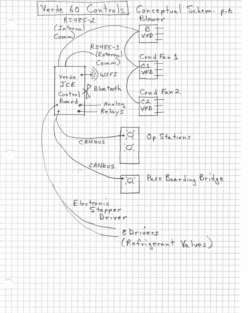
19 Wiring Diagrams 60Ton PCA Unit

20
21

22

23
40LM Hz INSTALLATION, START-UP AND SERVICE INSTRUCTIONS CHILLED WATER FAN COIL UNIT
 Carrier International Sdn. Bhd. Malaysia INSTALLATION, START-UP AND SERVICE INSTRUCTIONS CHILLED WATER FAN COIL UNIT 40LM 120-200 50Hz CONTENTS: Physical Data & Dimension 1-3 Safety Considerations 4 Rigging
SM Field Installed Electric Heat Kit
 SM Field Installed Electric Heat Kit HK050 HK100 HK150 HK200 Installation Manual 8733822029 (2018/07) US 2 SM Series Electric Heat Installation Manual Data subject to change 07.2018 8733822029 Installation
Installation Instructions
 CNPVP CNRVP Cased N Coils Upflow --- Downflow Heating --- Cooling Installation Instructions NOTE: Read the entire instruction manual before starting the installation. TABLE OF CONTENTS PAGE SAFETY CONSIDERATIONS...
Installation Instructions
 CNPVP CNRVP Cased N Coils Upflow --- Downflow Heating --- Cooling Installation Instructions NOTE: Read the entire instruction manual before starting the installation. TABLE OF CONTENTS PAGE SAFETY CONSIDERATIONS...
G Series. G Series Air Coils Installation ti Manual ENCASED/UNCASED AIR COILS. Geothermal/Water Source Heat Pumps R-410A Refrigerant 2-5 Ton
 G Series ENCASED/UNCASED AIR COILS Geothermal/Water Source Heat Pumps R-410A Refrigerant 2- Ton Dimensional Data G Series Air Coils Installation ti Manual Installation Information Maintenance IM1018AG1
PARALLEL RACK SYSTEM INSTALLATION & OPERATIONS MANUAL With Master Rack Compressor Sequencer
 PARALLEL RACK SYSTEM INSTALLATION & OPERATIONS MANUAL With Master Rack Compressor Sequencer 5/16 Rev. A 57-02509 2 Contents INTRODUCTION... 4 WARNING LABELS AND SAFETY INSTRUCTIONS... 5 PS SERIES PARALLEL
Installation Instructions
 Installation Instructions For Cased Coils Upflow-Downflow Heating-Cooling CK5A CK5B SUPPLY RETURN EVAPORATOR COIL DOWNFLOW UPFLOW SUPPLY Fig. 1 Typical Coil Installation NOTE: Read the entire instruction
Your safety and the safety of others are very important.
 VARIABLE SPEED ELECTRIC FURNACE INSTALLATION INSTRUCTIONS VARIABLE SPEED ELECTRIC FURNACE SAFETY...1 INSTALLATION REQUIREMENTS...2 Tools and Parts...2 Location Requirements...2 Installation Configurations...3
EcoAisle Thermal Containment System
 Guide Specifications EcoAisle Thermal Containment System THIS GUIDE SPECIFICATION IS WRITTEN IN ACCORDANCE WITH THE CONSTRUCTION SPECIFICATIONS INSTITUTE (CSI) MASTERFORMAT. THIS SECTION MUST BE CAREFULLY
Installation, Operation, and Maintenance Information
 Installation, Operation, and Maintenance Information Air Cooled Condensers 8-2016 Rev 0 Table of Contents General Safety Information 2 Inspection 2 Installation 2 6 Rigging and Assembly 2 Unit Location
WMHP Series R410a Heat Pump INSTALLATION INSTRUCTIONS
 WMHP Series R410a Heat Pump INSTALLATION INSTRUCTIONS **WARNING TO INSTALLER, SERVICE PERSONNEL AND OWNER** Altering the product or replacing parts with non authorized factory parts voids all warranty
RHGN-H: COMMERCIAL AIR HANDLER WITH VARIABLE FREQUENCY DRIVE (VFD) NOMINAL 10 TONS R-410A REFRIGERANT 2-STAGE AIR-FLOW
 NOMINAL 10 TONS R-410A REFRIGERANT 2-STAGE AIR-FLOW") INSTALLATION INSTRUCTIONS RHGN-H: COMMERCIAL AIR HANDLER WITH VARIABLE FREQUENCY DRIVE (VFD) NOMINAL 10 TONS R-410A REFRIGERANT 2-STAGE AIR-FLOW 92-106595-01-00 TABLE OF CONTENTS Introduction.......................................
INSTALLATION INSTRUCTIONS RHGN-H: COMMERCIAL AIR HANDLER WITH VARIABLE FREQUENCY DRIVE (VFD) NOMINAL 10 TONS R-410A REFRIGERANT 2-STAGE AIR-FLOW 92-106595-01-00 TABLE OF CONTENTS Introduction.......................................
OPERATION MANUAL. Move it. Hang it. Rack it. Stack it. MaxPower Corporation 230 Yuma Street Denver, CO
 OPERATION MANUAL Complete Instructions for and Operation MaxPower Corporation 230 Yuma Street Denver, CO 80223 800-576-3966 www.coolcube10.com Move it. Hang it. Rack it. Stack it. 05/05 P/N: 5-TC600-2510
Surna 25-Ton Chiller Operating & Maintenance Manual
 www.surna.com 303.993.5271 Surna 25-Ton Chiller Operating & Maintenance Manual Models: 300F3-3. 300F4-3, 300FW-3 Revised: July 2015 Table of Contents Warranty Information 4 Limited Warranty 4 Limitation
BOTTOM MOUNT REFRIGERATORS & FREEZERS Installation, Operation and Maintenance Instructions
 BOTTOM MOUNT REFRIGERATORS & FREEZERS Installation, Operation and Maintenance Instructions INSPECTION When the equipment is received, all items should be carefully checked against the Bill of Lading to
OPERATIONS AND MAINTENANCE MANUAL FOR THE 8-TON TURF CART ENVIRONMENTAL CONTROL UNIT (ECU) PART NUMBER
 PART NUMBER") OPERATIONS AND MAINTENANCE MANUAL FOR THE 8-TON TURF CART ENVIRONMENTAL CONTROL UNIT (ECU) PART NUMBER 2001927 Prepared by: 860 Douglas Way PO Box 530 Natural Bridge Station, VA 24579 1 1.0 SCOPE: This
OPERATIONS AND MAINTENANCE MANUAL FOR THE 8-TON TURF CART ENVIRONMENTAL CONTROL UNIT (ECU) PART NUMBER 2001927 Prepared by: 860 Douglas Way PO Box 530 Natural Bridge Station, VA 24579 1 1.0 SCOPE: This
ENVIRONMENTAL CONTROL UNIT (ECU) PART NUMBER OPERATIONS AND MAINTENANCE MANUAL
 PART NUMBER OPERATIONS AND MAINTENANCE MANUAL") ENVIRONMENTAL CONTROL UNIT (ECU) PART NUMBER 2001829 OPERATIONS AND MAINTENANCE MANUAL Prepared by: 860 Douglas Way PO Box 530 Natural Bridge Station, VA 24579 1.0 SCOPE: This Operations and Maintenance
ENVIRONMENTAL CONTROL UNIT (ECU) PART NUMBER 2001829 OPERATIONS AND MAINTENANCE MANUAL Prepared by: 860 Douglas Way PO Box 530 Natural Bridge Station, VA 24579 1.0 SCOPE: This Operations and Maintenance
Installation Instruction
 Installation Instruction Upflow Downflow Heating Cooling CC5A Uncased Coil CD5A Cased Coil SUPPLY RETURN EVAPORATOR COIL DOWNFLOW UPFLOW SUPPLY Fig. 1 Typical Installation of CD5A Cased Coil A96244 NOTE:
Installation Instructions
 Installation Instructions For Cased and Uncased Coils Upflow-Downflow Heating-Cooling CK5A, CK5B Cased CJ5A Uncased SUPPLY RETURN EVAPORATOR COIL DOWNFLOW UPFLOW SUPPLY Fig. 1 Typical Coil Installation
MHNCCX DX with Hot Water Heat Ceiling Concealed 4-Pipe Heat / Cool Fan Coil 12,000-36,000 BTUH
 MHNCCX DX with Hot Water Heat Ceiling Concealed 4-Pipe Heat / Cool Fan Coil 12,000-36,000 BTUH 318 MHNCCX NOMENCLATURE BREAKDOWN 4-Pipe Heat/Cool Ceiling Concealed Fan Coil MHNCCW- XX - XX Ceiling Concealed
Liebert InteleCool Warranty Inspection Check Sheet
 The following information must be fully completed and forwarded to your local Liebert sales office to establish your equipment warranty. Installer _ Address Owner Address Owner e-mail address Installation
ACT Cartridge Dust Collector
 IOM-101-1 ACT Cartridge Dust Collector Installation and Operation Manual ACT Dust Collectors CAUTION! Accidents happen, be careful and always follow all local and federal regulations! Fires and explosions
REFRIGERATED PREP TABLES Installation, Operation and Maintenance Instructions
 REFRIGERATED PREP TABLES Installation, Operation and Maintenance Instructions Please read this manual completely prior to installing and operating this equipment. This manual describes how to install,
Guide Specifications. HyperPod System PART 1 - GENERAL 1.01 SUMMARY
 Guide Specifications HyperPod System THIS GUIDE SPECIFICATION IS WRITTEN IN ACCORDANCE WITH THE CONSTRUCTION SPECIFICATIONS INSTITUTE (CSI) MASTERFORMAT. THIS SECTION MUST BE CAREFULLY REVIEWED AND EDITED
38ASB/CCARS240~600 (036~060) AIR-COOLED CONDENSING UNIT
 AIR-COOLED CONDENSING UNIT") Concepcion Carrier Air conditioning Company Philippines INSTALLATION, START-UP AND SERVICE INSTRUCTIONS 38ASB/CCARS240~600 (036~060) AIR-COOLED CONDENSING UNIT CONTENTS Safety Considerations 1 Complete
Concepcion Carrier Air conditioning Company Philippines INSTALLATION, START-UP AND SERVICE INSTRUCTIONS 38ASB/CCARS240~600 (036~060) AIR-COOLED CONDENSING UNIT CONTENTS Safety Considerations 1 Complete
Installation Instructions
 Electric Heaters 5 --- 20 kw SMALL PACKAGED PRODUCTS (SPP) Accessory Electric Heaters For 13 SEER, R---410A Manufactured Home Installation Instructions NOTE: The Dual Point Kit can only be installed on
T-Series Air Conditioner T20 Model
 INSTRUCTION MANUAL T-Series Air Conditioner T20 Model Protecting Electronics. Exceeding Expectations. McLean Cooling Technology 11611 Business Park Blvd N Champlin, MN 55316 USA Tel 763-323-8200 Fax 763-576-3200
T-SERIES Air Conditioner. T20 Model INSTRUCTION MANUAL nvent Rev. C P/N
 T-SERIES Air Conditioner T20 Model INSTRUCTION MANUAL Rev. C P/N 89114993 TABLE OF CONTENTS Warranty and Return Policy... 2 IMPORTANT NOTICE... 2 RECEIVING THE AIR CONDITIONER... 3 HANDLING AND TESTING
Operation Manual SCT14B and SCT18B. Inspection. 3 General Description. 3 General Requirements. 3 Standard Features.
 Spot Cooling Systems, Inc. 120 Century Drive Suite 00 Carrollton, TX 7006 00-6-776 Operation Manual SCT1B and SCT1B Warning! Improper installation, adjustment, alteration, service, or maintenance can cause
Installation Operation Maintenance
 Installation Operation Maintenance Series R Air-Cooled Helical Rotary Liquid Chiller RTAD 085-180 (50Hz) Standard, Free Cooling and Heat Recovery models RTAD-SVX01F-E4 General information Foreword These
ACT-HSC Series Heat Sink Coolers Sealed Enclosure Cooling Installation Guide
 ACT-HSC Series Heat Sink Coolers Sealed Enclosure Cooling Installation Guide SA44609 ACT-HSC-22 ACT-HSC-45 ACT-HSC-68 Sealed Enclosure Coolers Keep The Inside of your Enclosure Free of Dirt & Debris NEMA
INSTALLATION INSTRUCTIONS TXV Coils for Manufactured Housing EMA
 TXV Coils for Manufactured Housing EMA NOTE: Read the entire instruction manual before starting the installation. SAFETY CONSIDERATIONS Improper installation, adjustment, alteration, service, maintenance,
SPECTRACOOL Air Conditioner. N21 Model INSTRUCTION MANUAL nvent Rev. G P/N
 SPECTRACOOL Air Conditioner N21 Model INSTRUCTION MANUAL Rev. G P/N 89115088 TABLE OF CONTENTS WARRANTY AND RETURN POLICY...2 RECEIVING THE AIR CONDITIONER...3 HANDLING AND TESTING THE AIR CONDITIONER...3
MAXIMUM SERIES. Maximum Series portable chillers can be used on a variety of process applications that require 20 F to 70 F chilled water.
 Temperature Control Units Water & Oil 30-500 F Portable Chillers Air & Water-Cooled 20-70 F Central Chillers Air & Water-Cooled Packages & Modules 20-70 F Pump Tank Stations Chilled or Tower Water 200-3600
CS/CD/CP AIR COOLED CONDENSING UNITS (P/N E207120C R2)
") CS*/CD*/CP* Series Air Cooled Condensing Units Operating and Installation Manual CS/CD/CP AIR COOLED CONDENSING UNITS (P/N E207120C R2) TABLE OF CONTENTS I. Receipt of Equipment 2 II. Piping...4 III. System
CS*/CD*/CP* Series Air Cooled Condensing Units Operating and Installation Manual CS/CD/CP AIR COOLED CONDENSING UNITS (P/N E207120C R2) TABLE OF CONTENTS I. Receipt of Equipment 2 II. Piping...4 III. System
T-Series Air Conditioner T15 Model
 INSTRUCTION MANUAL T-Series Air Conditioner T15 Model Protecting Electronics. Exceeding Expectations. McLean Cooling Technology 11611 Business Park Blvd N Champlin, MN 55316 USA Tel 763-323-8200 Fax 763-576-3200
Fig. 1--Typical Coil Installation
 Installation Instructions For Cased Coils Upflow-Downflow Heating-Cooling CK5A,CK5B CK5P SUPPLY _RETURN EVAPORATOR_ COIL_ -'_41 DOWNFLOW FURNACE UPFLOW FURNACE / / _SUPPLY A_2_ Fig. 1--Typical Coil Installation
Standard and CELDEK Evaporative Cooler Modules Installation, Operation, and Maintenance Manual
 Standard and CELDEK Evaporative Cooler Modules Installation, Operation, and Maintenance Manual Standard Evaporative Cooler CELDEK Evaporative Cooler RECEIVING AND INSPECTION Upon receiving unit, check
Liebert DataMate (1-3 Ton) Warranty Inspection Check Sheet
 Warranty Inspection Check Sheet") The following information must be fully completed and forwarded to your local Liebert sales office to establish your equipment warranty. Installer Address Owner Address Owner e-mail address Installation
The following information must be fully completed and forwarded to your local Liebert sales office to establish your equipment warranty. Installer Address Owner Address Owner e-mail address Installation
Installation Instructions
 50ZPB, C, 50ZHB, C, PA3Z ---A, PH3Z ---A, PA4Z, PH4Z, PAJ4,PHJ4,WJA4,WJH4 SMALL PACKAGED PRODUCTS (SPP) Accessory Electric Heaters 5---20 kw For 14 SEER, R---410A Manufactured Home Installation Instructions
Liebert Small System MCD and PFH Condensers (1-5 Ton) Warranty Inspection Check Sheet
 Warranty Inspection Check Sheet") The following information must be fully completed and forwarded to your local Liebert sales office to establish your equipment warranty. Installer Address Owner Address Owner e-mail address Installation
The following information must be fully completed and forwarded to your local Liebert sales office to establish your equipment warranty. Installer Address Owner Address Owner e-mail address Installation
Submittal. Date: January 8, Customer P.O. Number: Customer Project Number: CARROLLTON, TX 75006
 Submittal Prepared For: All Bidders Sold To: Date: January 8, 209 Customer P.O. Customer Project Job Job Name: City of Carrollton Fire Splits 623 Beltline Road CARROLLTON, TX 75006 Trane U.S. Inc. dba
User s Information and Installation Instructions
 Outdoor Air Conditioner User s Information and Installation Instructions 13 SEER R-410A High Efficiency Split System These units have been designed and tested for capacity & efficiency in accordance with
PROAIR Air Conditioner. CR43 Model INSTRUCTION MANUAL nvent Rev. H P/N
 PROAIR Air Conditioner CR43 Model INSTRUCTION MANUAL Rev. H P/N 10-1008-130 TABLE OF CONTENTS Warranty and Return Policy...2 RECEIVING THE AIR CONDITIONER...3 HANDLING AND TESTING THE AIR CONDITIONER...3
Installation Instructions
 53DS --- 900 --- --- --- 092 Duct---Free Systems Accessory Power Ventilation Kit for In --- Ceiling Cassette Fan Coil Units Size 018 --- 036 Installation Instructions NOTE: Read and become familiar with
Packaged Air Conditioning Units. Owner s Guide to Operating and Maintaining Your Air Conditioner. This manual should be left with the owner.
 Packaged Air Conditioning Units Owner s Guide to Operating and Maintaining Your Air Conditioner ELECTRICAL SHOCK HAZARD. Failure to follow this warning could result in personal injury, Disconnect power
Installation Instructions
 PREFERREDT SERIES AIR CONDITIONER WITH PURONR REFRIGERANT 1-1/2 TO 5 NOMINAL TONS Installation Instructions Fig. 1 --- 538A NOTE: Read the entire instruction manual before starting the installation. TABLE
OWNER S MANUAL. Vintage Signature Series models: AC750, AC1050, AC1100, AC1250, AC1500, AC1750. Proudly Made in the USA.
 OWNER S MANUAL Vintage Signature Series models: AC750, AC1050, AC1100, AC1250, AC1500, AC1750 Proudly Made in the USA support@aquacomfort.com 888-475-7443 Manufacturing High Quality, High Efficiency Heat
PROAIR Air Conditioner. CR29 Model INSTRUCTION MANUAL nvent Rev. I P/N
 PROAIR Air Conditioner CR29 Model INSTRUCTION MANUAL Rev. I P/N 89104461 TABLE OF CONTENTS Warranty and Return Policy...2 RECEIVING THE AIR CONDITIONER...3 HANDLING AND TESTING THE AIR CONDITIONER...3
A. Product Data: Include rated capacities, operating characteristics, furnished specialties, and accessories.
 SECTION 238113 - PACKAGED TERMINAL AIR CONDITIONERS PART 1 - GENERAL 1.1 RELATED DOCUMENTS A. Drawings and general provisions of the Contract, including General and Supplementary Conditions and Division
UNDERCOUNTER REFRIGERATORS AND FREEZERS Installation, Operation and Maintenance Instructions
 UNDERCOUNTER REFRIGERATORS AND FREEZERS Installation, Operation and Maintenance Instructions Please read this manual completely prior to installing and operating this equipment. This manual describes how
π H-6621 INDUSTRIAL DEHUMIDIFIER WARNINGS SPECIFICATIONS uline.com WATER REMOVAL ELECTRICAL REQUIREMENTS BUILT-IN ELECTRICAL SAFETY
 π H-6621 INDUSTRIAL DEHUMIDIFIER 1-800-295-5510 uline.com WARNINGS Plug into a grounded 3 prong outlet. Do not remove ground prong. Do not use an adapter. Do not use an extension cord if possible. Failure
Installation Instructions
 Electric Heaters 5 --- 20 kw SMALL PACKAGED PRODUCTS (SPP) Accessory Electric Heaters For 13 SEER, R---410A, Z Chassis Installation Instructions NOTE: Read the entire instruction manual before starting
BOTTOM MOUNT REFRIGERATORS AND FREEZERS Installation, Operation and Maintenance Instructions
 BOTTOM MOUNT REFRIGERATORS AND FREEZERS Installation, Operation and Maintenance Instructions INSPECTION When the equipment is received, all items should be carefully checked against the Bill of Lading
Ceiling Concealed Fan-Coil Unit
 Installation & Maintenance Manual IM 745 Group: Fan-coil Part Number: 106333001 Date: November 2009 Ceiling Concealed Fan-Coil Unit Models: THC02, THC03, THC04, THC06, THC08, THC10, THC12 Table of Contents
USER S MANUAL AND INSTALLATION INSTRUCTIONS IMPORTANT
 USER S MANUAL AND INSTALLATION INSTRUCTIONS P3BD Series 13 SEER Single Package Air Conditioner IMPORTANT Read this owner information to become familiar with the capabilities and use of your appliance.
T-Series Air Conditioner T53 Model
 INSTRUCTION MANUAL T-Series Air Conditioner T53 Model Protecting Electronics. Exceeding Expectations. McLean Cooling Technology 11611 Business Park Blvd N Champlin, MN 55316 USA Tel 763-323-8200 Fax 763-576-3200
T-SERIES Air Conditioner. T29 Model INSTRUCTION MANUAL nvent Rev. I P/N
 T-SERIES Air Conditioner T29 Model INSTRUCTION MANUAL Rev. I P/N 89104464 TABLE OF CONTENTS Warranty and Return Policy...2 IMPORTANT NOTICE...2 RECEIVING THE AIR CONDITIONER...3 HANDLING AND TESTING THE
Standard and CELDEK Evaporative Cooler Modules Installation, Operation, and Maintenance Manual
 Standard and CELDEK Evaporative Cooler Modules Installation, Operation, and Maintenance Manual Standard Evaporative Cooler CELDEK Evaporative Cooler RECEIVING AND INSPECTION Upon receiving unit, check
CELDEK Evaporative Cooler Module Installation, Operation, and Maintenance Manual. CELDEK Evaporative Cooler
 CELDEK Evaporative Cooler Module Installation, Operation, and Maintenance Manual CELDEK Evaporative Cooler RECEIVING AND INSPECTION Upon receiving unit, check for any interior and exterior damage, and
PROAIR Air Conditioner. CR23 Model INSTRUCTION MANUAL nvent Rev. D P/N
 PROAIR Air Conditioner CR23 Model INSTRUCTION MANUAL Rev. D P/N 89112522 TABLE OF CONTENTS Warranty and Return Policy...2 RECEIVING THE AIR CONDITIONER...3 HANDLING AND TESTING THE AIR CONDITIONER...3
OWNER S MANUAL. Vintage Classic HEAT COOL models. Proudly Made in the USA
 OWNER S MANUAL Vintage Classic HEAT COOL models Proudly Made in the USA support@aquacomfort.com www.aquacomfort.com/service-and-support 888-475-7443 Manufacturing High Quality, High Efficiency Heat Pump
Installation Instructions
 Evaporator Coil A Coil --- Cased Multipoise NOTE: Read the entire instruction manual before starting the installation. TABLE OF CONTENTS PAGE SAFETY CONSIDERATIONS... 1 INTRODUCTION... 1 INSTALLATION...
T-SERIES Air Conditioner. T50 Model INSTRUCTION MANUAL nvent Rev. F P/N
 T-SERIES Air Conditioner T50 Model INSTRUCTION MANUAL Rev. F P/N 10-1008-203 TABLE OF CONTENTS Warranty and Return Policy...2 RECEIVING THE AIR CONDITIONER...3 HANDLING AND TESTING THE AIR CONDITIONER...3
Installation Instructions Part No , Part No Part No
 Torsion-Flex Motor mount for PSC motors and Rigid-Mount for ECM motors Replacement Kit Cancels: New Installation Instructions Part No. 327752-401, Part No. 327753-401 Part No. 327754-401 IIK-310A-45-11
C. ASME Compliance: Fabricate and label water chiller heat exchangers to comply with ASME Boiler and Pressure Vessel Code: Section VIII, Division 1.
 SECTION 236426 - ROTARY-SCREW WATER CHILLERS PART 1 - GENERAL 1.1 SUMMARY A. This Section includes packaged, water cooled or air cooled as scheduled, electric-motor-driven, rotary-screw water chillers
A. Section includes split-system air-conditioning units consisting of separate evaporator-fan and compressor-condenser components.
 Page 238126-1 SECTION 238126 - This Section includes requirements for the LEED Rating System. However, equipment specified in this Section may not qualify for LEED Rating System prerequisites and credits.
COLMAC COIL. Installation, Operation, and Maintenance ENG Rev A. Air Cooled Fluid Coolers. Contents. When you want Quality, specify COLMAC!
 COIL Manufacturing Inc. When you want Quality, specify COLMAC! Installation, Operation, and Maintenance ENG00018621 Rev A Air Cooled Fluid Coolers Contents 1. SAFETY INSTRUCTIONS... 1 2. MODEL NOMECLATURE...
OPERATING & MAINTENANCE MANUAL HORIZONTAL WATER SOURCE HEAT PUMP. World class comfort.
 OPERATING & MAINTENANCE MANUAL HORIZONTAL WATER SOURCE HEAT PUMP World class comfort. welcome Congratulations on your selection of Ice Air Water Source Heat Pumps (WSHPs) for your comfort conditioning
T-SERIES Air Conditioner. T43 Model INSTRUCTION MANUAL nvent Rev. I P/N
 T-SERIES Air Conditioner T43 Model INSTRUCTION MANUAL Rev. I P/N 10-1008-145 TABLE OF CONTENTS Warranty and Return Policy...2 IMPORTANT NOTICE...2 RECEIVING THE AIR CONDITIONER...3 HANDLING AND TESTING
DBF 4XL Dryer Booster Fans
 Installation and Operation Manual Item #: 401315 Rev Date: 050814 DBF 4XL Dryer Booster Fans DBF4XL Kit Includes: Dryer Booster Fan, 1 pc Fan Mounting Bracket and Hardware, 1 pc Wall Label (Mount on wasll
Installation Instructions
 CNPHP Cased N Coils Horizontal Heating --- Cooling NOTE: Read the entire instruction manual before starting the installation. TABLE OF CONTENTS PAGE SAFETY CONSIDERATIONS... 1 INTRODUCTION... 1 INSTALLATION...
SPX SERIES PACKAGED AIR CONDITIONING/HEAT PUMP UNITS INSTALLATION, OPERATION AND MAINTENANCE INSTRUCTIONS
 SPX SERIES PACKAGED AIR CONDITIONING/HEAT PUMP UNITS INSTALLATION, OPERATION AND MAINTENANCE INSTRUCTIONS **WARNING TO INSTALLER, SERVICE PERSONNEL AND OWNER** Altering the product or replacing parts with
Installation Instructions
 NAHB00501WK Twinning Kit for HSI Single-Stage Condensing and Non-Condensing Gas Furnaces Installation Instructions NOTE: Read the entire instruction manual before starting the installation. SAFETY CONSIDERATIONS
NON-CYCLING REFRIGERATED AIR/GAS DRYERS QPNC 75 to QPNC 250 OPERATOR S MANUAL
 NON-CYCLING REFRIGERATED AIR/GAS DRYERS QPNC 75 to QPNC 250 OPERATOR S MANUAL DATE OF PURCHASE: MODEL: SERIAL NO.: Record above information from nameplate. Retain this information for future reference.
INSTALLATION INSTRUCTIONS Cased N Coil, Horizontal ENH4X
 INSTALLATION INSTRUCTIONS Cased N Coil, Horizontal ENH4X NOTE: Read the entire instruction manual before starting the installation. TABLE OF CONTENTS PAGE SAFETY CONSIDERATIONS... 1 INTRODUCTION... 1 INSTALLATION...
Installation Instructions
 Installation Instructions Part No. 30RA-900---057 and 30RA-900---060 30RAP010-150 Remote Cooler Mounting Accessory SAFETY CONSIDERATIONS Installation of this accessory can be hazardous due to system pressures,
OPERATION & MAINTENANCE MANUAL RHS680
 OPERATION & MAINTENANCE MANUAL RHS680 Refrigerant Handling System 4075 East Market Street York, PA 17402 800-468-2321 tech@rtitech.com Manual P/N 035-80740-00 (Rev 1- May 22, 2001) TABLE OF CONTENTS Startup
Owner s Information Manual
 50EZ---A and 50VT ---A Comfort and Performance 13 and 14 SEER Single Packaged Heat Pump System With PuronR (R ---410A) Refrigerant Single and Three Phase 2---5 Nominal Tons (Sizes 24---60) Owner s Information
TABLE OF CONTENTS INTRODUCTION. NOTE: Read the entire instruction manual before starting the installation.
 Installation NOTE: Read the entire instruction manual before starting the installation. TABLE OF CONTENTS PAGE SAFETY CONSIDERATIONS... 1 INTRODUCTION... 1 INSTALLATION... 2 Inspect Equipment... 2 Select
Installation, Operation, and Maintenance Information
 Installation, Operation, and Maintenance Information Low Velocity Unit Coolers Bulletin No. IOM 110.3 Table of Contents Inspection... 2 Installation... 2 4 General... 2 Location... 2 Drain Line... 3 Refrigerant
Split System Heat Pump Product Data
 Split System Heat Pump Product XR15 4TWR5 1 1 /2-5 Tons PUB. NO. 22-1832-10 Features and Benefits CLIMATUFF compressor Efficiency up to 17.0 SEER and 9.0 HSPF All aluminum SPINE FIN coil WEATHERGUARD fasteners
Commercial Water Source Heat Pump Water Heater Operations and Installation Manual
 GEYSER C-250W Commercial Water Source Heat Pump Water Heater Operations and Installation Manual Geyser 250W Manual Version 2.2 Nyle Systems 12 Stevens Rd Brewer, ME 04412 www.nyle.com info@nyle.com 800-777-6953
HEATING AND VENTILATION
 SECTION 14-102.04 14-102.04/ 1 2007OC19 DESCRIPTION The heating, ventilation and air conditioning (HVAC) system is designed to optimize passenger comfort. The system regulates interior vehicle atmosphere,
maintenance should only be performed by a trained, qualified person. Consumer service is recommended only for filter replacement.
 AHF / AHK SERIES AIR HANDLING UNITS INSTALLATION GUIDE GENERAL The AHF / AHK series is designed for horizontal recessed installations in a furred down area, above a suspended ceiling or recessed in the
GENESIS Air Conditioners. All Models INSTRUCTION MANUAL nvent Rev. K P/N
 GENESIS Air Conditioners All Models INSTRUCTION MANUAL Rev. K P/N 89104462 TABLE OF CONTENTS Warranty and Return Policy...2 RECEIVING THE AIR CONDITIONER...3 HANDLING AND TESTING THE AIR CONDITIONER...3
Liebert Xtreme Density Chiller (XDC) Unit Warranty Inspection Check Sheet
 Unit Warranty Inspection Check Sheet") The following information must be completed and forwarded to your local Liebert sales office to establish your equipment warranty. Installer Address Owner Address Owner e-mail address Date of Installation:
The following information must be completed and forwarded to your local Liebert sales office to establish your equipment warranty. Installer Address Owner Address Owner e-mail address Date of Installation:
AMERICAN STANDARD 14 MODELS 4A7B E
 SPLIT SYSTEM COOLING 1 1 / 2 5 ton AMERICAN STANDARD 14 MODELS 4A7B4018-60E PUB. NO. 12-1290-02 June 2009 Features and Benefits DURaTION compressor Efficiency up to 16.0 SEER All aluminum Spine Fin coil
Split System Heat Pump Product Data
 Split System Heat Pump Product XL 15i 4TWX5018 42A, 049E, 061E 1½ 5 Tons PUB. NO. 22-1800-07 Features and Benefits Climatuff compressor Efficiency up to 16.00 SEER and 9.0 HSPF All aluminum Spine Fin coil
Installation, Operation & Maintenance: Field-Installed Electric Heater for RXT Series Units
 P.O. Box 245 Syracuse, NY 13211 www.roth-america.com 888-266-7684 Installation, Operation & Maintenance: Field-Installed Electric Heater for RXT Series Units P/N: 2300100902 Table of Contents: Section
Residential Piping and Long Line Guideline
 AC / HP R-410A Refrigerant Systems Single-Stage, Two-Stage and Variable Speed Models Residential Piping and Long Line Guideline TABLE OF CONTENTS Safety Considerations... 2 Definitions... 2 Introduction...
BESB Box Ventilator USA CAN. Product Information. Mechanical Installation. ... Chapter 3. Electrical Installation. ... Chapter 4
 Installation & Operating Manual BESB Box Ventilator USA CAN Product Information... Chapter 1 + 2 Mechanical Installation... Chapter 3 Electrical Installation... Chapter 4 Start Up and Configuration...
PARAGON Commercial Refrigeration Controls
 PARAGON Commercial Refrigeration Controls ERC 2 Electronic Refrigeration Control The ERC 2 Electronic Refrigeration Control is a microprocessor-based electronic controller designed to control both the
Design Guide 2008 Fully Integrated Models 24" and 48"
 Design Guide 2008 Fully Integrated Models 24" and 48" 7082440-01 Welcome Liebherr's engineering excellence in Germany provides the largest selection of freezers, refrigerators and wine refrigerators worldwide.
Installation Instructions
 Installation Instructions EHMA SERIES ELECTRIC HEATERS FOR PAM3 SERIES PACKAGE AIR CONDITIONERS PHM3 SERIES PACKAGE HEAT PUMPS TABLE OF CONTENTS SAFE INSTALLATION REQUIREMENTS... 2 GENERAL INFORMATION...
Split System Cooling Product Data
 Split System Cooling Product Data XR 13 4TTR3018-060 1½ 5 Tons PUB. NO. 22-1842-05 Features and Benefits Climatuff compressor Efficiency up to 14.00 SEER All aluminum Spine Fin coil WeatherGuard fasteners
SYSTEM 2000 CHILLED WATER (CAC) EC SERIES -INSTALLATION OPERATIONS AND MAINTENANCE MANUAL-
 EC SERIES -INSTALLATION OPERATIONS AND MAINTENANCE MANUAL-") SYSTEM 2000 CHILLED WATER (CAC) EC SERIES -INSTALLATION OPERATIONS AND MAINTENANCE MANUAL- 8167 Byron Road Whittier, CA 90606 Phone: (562) 945-8971 Fax: (562) 696-0724 www.compu-aire.com Table of Contents
SYSTEM 2000 CHILLED WATER (CAC) EC SERIES -INSTALLATION OPERATIONS AND MAINTENANCE MANUAL- 8167 Byron Road Whittier, CA 90606 Phone: (562) 945-8971 Fax: (562) 696-0724 www.compu-aire.com Table of Contents
CHILLER. Operator s & Installation Manual
 CHILLER MODELS: CH1001-A Operator s & Installation Manual Release Date: August 9, 2002 Publication Number: 620914301 Revision Date: May 6, 2010 Revision: E Visit the IMI Cornelius web site at www.cornelius.com
Installation Instructions
 24AHA4 Performance Series Air Conditioner with Puron Refrigerant 1-1/2 to 5 Nominal Tons Installation Instructions Fig. 1-24AHA4 A07532 SAFETY CONSIDERATIONS Improper installation, adjustment, alteration,
Operation and Maintenance Manual
 Warranty Information Ritchie Engineering guarantees YELLOW JACKET products to be free of defective material and workmanship which could affect the life of the product when used for the purpose for which