Owner's Manual. Spirit - Gas Stove Room Heater. - July, Listed OMNI
|
|
|
- Dana Singleton
- 6 years ago
- Views:
Transcription

1 Owner's Manual - July, WARNING: If the information in this manual is not followed exactly, a fire or explosion may result causing property damage, personal injury or loss of life. - Do not store or use gasoline or other flammable vapors and liquids in the vicinity of this or any other appliance. - WHAT TO DO IF YOU SMELL GAS Do not try to light any appliance. Do not touch any electrical switch; do not use any phone in your building. Immediately call gas supplier from a neighbor's phone. Follow the gas supplier's instructions. If you cannot reach your gas supplier, call the fire department. - Installation and service must be performed by a qualified installer, service agency or the gas supplier. Spirit - Gas Stove Room Heater th Place N.E. Kirkland, WA OMNI Listed

2 PAGE 2 SAFETY PRECAUTIONS IF YOU SMELL GAS: * Do not light any appliance * Extinguish any open flame * Do not touch any electrical switch or plug or unplug anything * Open windows and vacate building * Call gas supplier from neighbor's house, if not reached, call fire department This unit must be installed by a qualified installer to prevent the possibility of an explosion. Your dealer will know the requirements in your area and can inform you of those people considered qualified. The room heater should be inspected before use and at least annually by a qualified service person. More frequent cleaning may be required due to excessive lint from carpeting, bedding material, etc. The instructions in this manual must be strictly adhered to. Do not use makeshift methods or compromise in the installation. Improper installation will void the warranty and safety listing. THIS CONTROL HAS BEEN CONVERTED FOR NATURAL GAS THIS CONTROL HAS BEEN CONVERTED TO LP This heater is either approved for natural gas (NG) or for propane (LP). Burning the incorrect fuel will void the warranty and safety listing and may cause an extreme safety hazard. Direct questions about the type of fuel used to your dealer. Check the label and flame adjust knob on the gas control valve. Ok Contact your local building officials to obtain a permit and information on any installation restrictions or inspection requirements in your area. Notify your insurance company of this heater as well. It is imperative that control compartments, screens, or circulating air passageways of the heater be kept clean and free of obstructions. These areas provide the air necessary for safe operation.? If the flame becomes sooty, dark orange in color, or extremely tall, do not operate the heater. Call your dealer and arrange for proper servicing. Do not operate the heater if it is not operating properly in any fashion or if you are uncertain. Call your dealer for a full explanation of your heater and what to expect. Gas Do not store or use gasoline or other flammable liquids in the vicinity of this heater. Keep all furniture or other combustible items at least 36" away from the front of the heater. Do not operate if any portion of the heater was submerged in water or if any corrosion occurs.
3 SAFETY PRECAUTIONS (CONTINUED) PAGE 3 Do not place clothing or other flammable items on or near the heater. Because this heater can be controlled by a thermostat there is a possibility of the heater turning on and igniting any items placed on or near it. The viewing glass should be opened for service only (see the maintenance section of this manual). Any safety screen or guard removed for servicing must be replaced prior to operating the heater. Operate the heater according to the instructions included in this manual. If the main burners do not start correctly turn the gas off at the gas control valve and call your dealer for service. This unit is not for use with solid fuel Do not place anything inside the firebox (except the included fiber logs). If the fiber logs become damaged, replace with Travis Industries log set. Do not touch the hot surfaces of the heater. Educate all children of the danger of a hightemperature heater. Young children should be supervised when they are in the same room as the heater. Instruct everyone in the house how to shut gas off to the appliance and at the gas main shutoff valve. The gas main shutoff valve is usually next to the gas meter or propane tank and requires a wrench to shut off. This Manual Light the heater using the built-in piezo igniter. Do not use matches or any other external device to light your heater. Never remove, replace, modify or substitute any part of the heater unless instructions are given in this manual. All other work must be done by a trained technician. Don't modify or replace orifices. Allow the heater to cool before carrying out any maintenance or cleaning. The pilot flame must contact the thermopile and thermocouple (see the illustration to the left). If it does not, turn the gas control valve to "OFF" and call your dealer. Do not throw this manual away. This manual has important operating and maintenance instructions that you will need at a later time. Always follow the instructions in this manual. Plug the heater into a 115V grounded electrical outlet. Do not remove the grounding plug. Don't route the electrical cord in front of or over the heater Travis Industries, Inc. grants no warranty, implied or stated, for the installation or maintenance of your heater, and assumes no responsibility of any consequential damage(s).
4 PAGE 4 TABLE OF CONTENTS General Information Introduction & Important Information... 1 Safety Precautions... 2 Features & Specifications... 5 Stove Installation Heater Placement... 6 Floor Protection... 7 Vent Requirements... 7 Gas Line Install... 8 Finalizing the Installation... 9 Operating Your Heater Reviewing the Installation Before You Begin Location of Controls Starting The Pilot Running Your Heater Starting the Heater for the First Time Turning the Heater On and Off Adjusting the Flame Height Adjusting the Blower Speed Normal Operating Sounds Maintaining Your Heater Inspecting the Firebox Installing and Removing the Logs and Coals Inspecting the Door Replacing the Door Gasket Replacing the Glass or Glass Gasket Troubleshooting Troubleshooting Table How this Heater Works What Turns the Main Burners On and Off Why Nothing Should Be Placed Against the Heater What Prevents Gas Buildup Wiring Diagram Replacement Parts List Warranty Warranty Listing Information Listing Information Optional Equipment Legs Pedestal Remote Control Thermostat Re-Routing the Power Cord to the Left or Rear of the Heater Index Index... 32
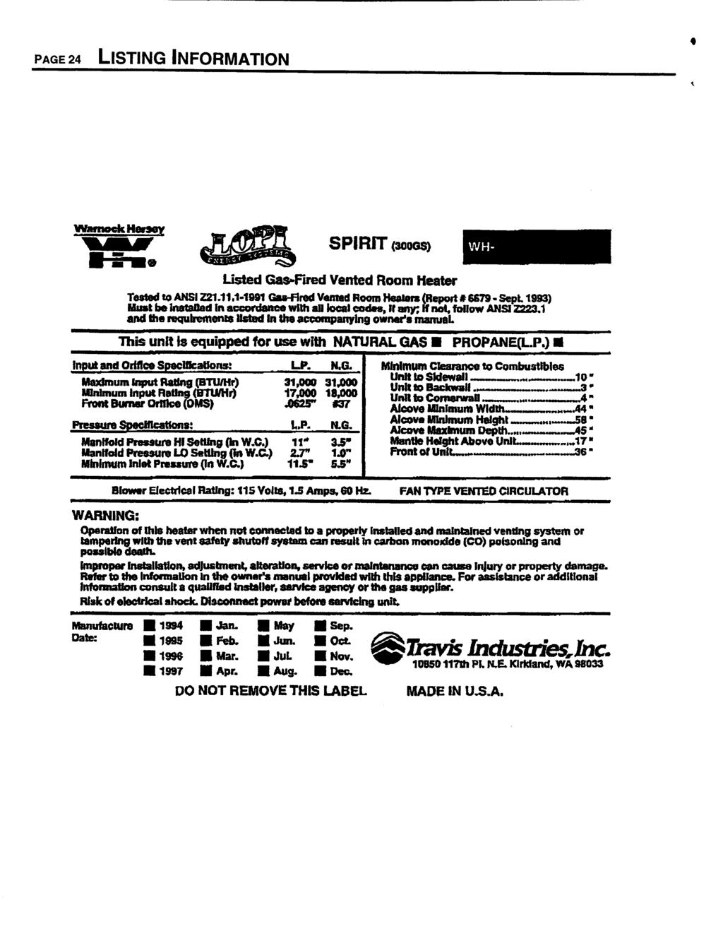
5 FEATURES AND SPECIFICATIONS PAGE 5 Features: Works During Power Outages (utilizes millivolt system) High Efficiency; up to 80% for Natural Gas, 82% for LP (Steady State) Optional Thermostat or Remote Control Realistic "Wood Fire" Look Convenient Operating Controls Variable-Rate Heat Output Quiet Blower for Effective Heat Distribution Low Maintenance Heating Specifications: Spirit Natural Gas Spirit LP (propane) Approximate Maximum Heating Capacity (in square feet)* 900-1, ,500 High Burn Input Rate (In BTU's)** 31,000 31,000 Low Burn Input Rate (In BTU's)** 18,000 17,000 AFUE Efficiency 70.0% 70.0% * Heating capacity will vary depending on the home's floor plan, degree of insulation, and the outside temperature. It is also affected by the natural gas or LP BTU rating. ** To measure the net BTU's, multiply the BTU input by the efficiency percentage (80% for natural gas, 82% for LP). Spirit Dimensions 20 3/4" 24" HEIGHT*: With Pedestal 34 7/8" ** With Brass Legs 30 7/8" With Cast Legs 30 7/8" With Black Legs 29 1/2" 5 1/2" * Subtract 4" to reach the base of the flue collar **Use the Lopi pedestal, part # Vent Opening Diameter = 4" Weight = 205 Pounds Electrical Specifications: Blower Electrical Rating: 115 Volts, 1.3 Amps, 60 Hz (150 watts on high) Fuel: The heater is designed either for natural gas or for propane (but not for both). Check the sticker on the top of the gas control valve. Emissions: This unit has passed the ANSI emission standards for vented room heaters as tested by Warnock Hersey, LTD.
6 PAGE 6 STOVE INSTALLATION - For qualified installers only! This appliance must be installed in accordance with all local codes, if any; if not, follow ANSI Z223.1 and the requirements listed in this manual. Failure to follow all of the requirements may result in property damage, bodily injury, or even death. Check with local building officials for any permits required for installation of this gas heater and notify your insurance company before hooking up this heater. The requirements listed below are divided into sections. All requirements must be met simultaneously. The order of installation is not rigid Ð the qualified installer should follow the procedure best suited for the installation. Heater Placement The heater must be placed so the following requirements are met: Stove must be placed so that no combustibles are within, or can swing within (e.g. drapes, doors), 36" of the front of the heater The stove must be placed on a set of Travis Industries legs or pedestal Heater must be installed on a level, secure floor The stove must not be placed so the vents below the ashlip, above the door, along the sides of stove, or along the back of the heater can become blocked Alcove Installations If the ceiling height is under 7 feet, the following requirements must be met: Minimum height 58" Maximum depth 48" Minimum width 44" STRAIGHT INSTALLATION (see the illustration below) 10" clearance from the top of the heater to the sidewall 3" clearance from the top of the heater to the backwall CORNER INSTALLATION (see the illustration below) 4" clearance from the rear top corner of heater to the cornerwall (at a 45 angle) HINT: REDUCING CLEARANCES - Clearances may be reduced by methods specified in NFPA 211, listed wall shields, pipe shields, or other means approved by local building or fire officials. Straight Installation Backwall Corner Installation Cornerwall 4" MIn. (to top of stove) Cornerwall 3" MIn. (to top of stove) Sidewall 10" MIn. (to top of stove) When the stove is installed directly on carpeting, vinyl, or other combustible material other than wood flooring, the stove must be installed on a metal or wood protection panel extending the full width and depth of the stove.
7 STOVE INSTALLATION (CONT.) - For qualified installers only! PAGE 7 Floor Protection When the stove is installed directly on carpeting, vinyl or other combustible material other than wood flooring, the stove must be installed on a metal or wood protection panel extending the full width and depth of the stove. Vent Requirements The vent must be installed in accordance with all local codes, if any; if not, follow ANSI and the requirements listed below. Furthermore, the vent must be installed to meet the installation requirements of the vent manufacturer. Minimum 5' vertical rise from top of stove (see the illustration below) The horizontal run may not exceed 50% of the vertical rise Use 4" dia. B vent for entire system from one manufacturer (don't mix brands) - or - Use high temperature factory built chimney and connector with listed gas chimney liner running the entire length The vent must not service another appliance 1" clearance to all combustibles must be maintained Must meet all of the vent manufacturer's requirements Vent termination must be above the roof and not below any eaves or overhangs Vent must terminate a minimum 1' above the roof. Do not block gas vent termination Min. 5' Rise Type B Vent Maintain 1" minimum clearance Provide a 1/4" rise for every 12" run. Min. 5' Rise High temperature factory built chimney and connector The total horizontal run must not exceed 50% of the vertical rise Listed Gas Chimney Liner Standard Installation Exterior Vent Chimney with Liner
8 PAGE 8 STOVE INSTALLATION (CONT.) - For qualified installers only! Vent Requirements (continued) Vent termination must have an approved cap (to prevent water from entering) Vent termination must not be located where it will become plugged by snow or other material Vent termination must be 1' above the roof and meet the requirements outlined in ANSI 223.1, section ' Minimum Note: ANSI 223.1, section outlines additional requirements for gas vent terminations. If your installation involves a roof with a slope greater than 6/12 or if a wall or other verical obstruction is within 8' of the vent termination, the vent termination will need to be taller. Refer to ANSI for full details. NOTE: When installed, the vent must provide suitable draft for the appliance. Other factors, such as exhaust fans, may create negative pressure inside the home and cause down drafts. Additional vent height may be required in these circumstances. Draft Hood Vent Collar TO TEST THE DRAFT: Remove the back panel. Start the heater and check the perimeter of the draft hood with a gas detector or smoke. If combustion products leak out the draft hood, the vent may need to be taller to improve draft. Spill Switch Gas Line Install The gas line must be installed in accordance with all local codes, if any; if not, follow ANSI and the requirements listed below. Gas Line Connection: The gas inlet is a male 3/8" NPT This appliance requires a shutoff valve upstream of the appliance. This valve must be accessible and within 3 feet of the heater.
9 Gas Inlet Location: STOVE INSTALLATION (CONT.) - For qualified installers only! PAGE 9 C L 7 1/2" (from center of stove) LOCATION OF THE GAS INLET CENTER: HEIGHT: From Base of Stove 1 1/2" With Pedestal 12 3/4" With Brass Legs 9 3/8" With Cast Legs 9 3/8" With Black Legs 8" The 3/8" N.P.T. gas inlet portrudes 1 1/2" from the back edge of the stove. Gas Pressure: Minimum Input Pressure Natural Gas 7" W.C. Propane 11" W.C. If the pressure is not sufficient, make sure the piping used is large enough, the supply regulator is adequately adjusted, and the total gas load for the residence does not exceed the amount supplied. The supply regulator (the regulator that attaches directly to the residence inlet or to the propane tank) should supply gas at the suggested input pressure listed above. Contact the local gas supplier if the regulator is at an improper pressure. Purging the Gas Line: The gas line must be properly purged to release all air in the gas line prior to starting the heater. Finalizing the Installation Before starting, all gas line joints must be leak tested. Optional equipment must be installed (instructions are in the rear of this manual). The ceramic logs must be placed inside the firebox (see the section "Installing the Logs and Coals" in the maintenance section of this manual). Start the heater and check for proper performance. Review the operations portion of this manual to make sure the owner understands the operation of the heater. Note: See the instructions "Re-Routing the Power Cord to the Left or Rear of the Heater" in the optional equipment section of this manual to re-route the power cord.
10 PAGE 10 REVIEWING THE INSTALLATION The check off list below details the installation concerns that you, the consumer, should know prior to starting the heater. This information is very important and must be checked off. ( ) There are no combustible items placed within 36" of the front of the heater or swing within 36" of the front of heater. This includes furniture, doors, drapes, etc. Combustible 36" Minimum ( ) No combustibles are within 1" of the exhaust vent. Due too high temperatures, the room heater should be located out of traffic and away from combustibles. This includes drywall, drapes, window sills, etc. If any question exists, call your dealer for a full explanation. Min.1" clearance Gas Vent Combustible ( ) The location of the GAS MAIN SHUTOFF VALVE. It is usually directly next to the gas meter or propane tank and may require a wrench to shut off. Everyone in the house should know where the gas main shutoff valve is and how to turn it off. On most valves this is ON On most valves this is OFF ( ) All of the necessary permits and installation information have been obtained for your records. This includes the permits from building officials, receipts, and this manual. O k OWNER'S MANUAL Permits Receipts This Manual ( ) The operation card included with the heater slides out from behind the access panel. If you can not find it, call your dealer for details. This card includes important operation information that must be kept with the heater at all times.
11 Before You Begin OPERATING YOUR HEATER PAGE 11 READ THIS ENTIRE MANUAL BEFORE YOU USE YOUR NEW HEATER. FAILURE TO FOLLOW THE INSTRUCTIONS MAY RESULT IN PROPERTY DAMAGE, BODILY INJURY, OR EVEN DEATH. Before starting your heater make sure you have read the section titled Safety Precautions. Any questions should be referred to your dealer. Location of Controls - See explanation below Gas Control Knob Flame Adjust Knob ON/OFF Switch PILOT IGNITER BLOWER Dial With the access panel flipped down the controls can be accessed. MAIN BURNER ON OFF PILOT IGNITER OFF HI LO BLOWER Blower Knob On/Off Switch Pilot Igniter Gas Control Knob This knob controls the speed of the internal convection blower that pushes the heated air into the room. This control is used to turn the heater on and off. The pilot igniter is used only to start the pilot. When pressed, it sends an electrical charge to the pilot assembly. This creates a blue spark directly next to the pilot, igniting the pilot flame. This knob is used to control gas to the heater and for starting the pilot. There are three positions, ON, OFF, & PILOT. The pointer directly below the knob indicates the position this knob is in. Flame Adjust Knob This knob controls the flame height from low ("LO") to high ("HI"). The pointer to the upper right of the knob points to the position this knob is in.? If using a remote control or thermostat, the On/Off Switch must be left "ON". Turning the On/Off Switch "OFF" will keep the heater off always.
12 PAGE 12 OPERATING YOUR HEATER (CONTINUED) Starting The Pilot Flame A B The pilot flame is required to ignite the main burners (it also plays a safety role). It should be left on once lit. It will stay lit unless the gas control valve is turned to "OFF". However, the pilot will go out if the gas is shut off or if the heater malfunctions. If the pilot turns off frequently, call your dealer for information. To start the pilot follow the directions below: Push the gas control knob in slightly and turn it to the "OFF" position. The knob will not turn from "ON" to "OFF" unless the knob is depressed slightly. Wait five minutes to let any gas that may have accumulated inside the firebox escape. If you smell gas, follow the directions on the cover "IF YOU SMELL GAS". A C L OT PI ON ON OFF PILOT ADJ B 5 minutes PILOT IGNITER PILOT SPARK C Turn the gas control knob to the "PILOT" position and press the knob in, this will allow gas to flow to the pilot light. Press the red button on the pilot igniter repeatedly until you see the pilot light. KEEP THE GAS CONTROL KNOB DEPRESSED FOR 30 SECONDS ONCE IT IS LIT. Note: If the pilot does not light after several tries, call your dealer for service. L OT ON L OT PI OFF PILOT ADJ PI OFF PILOT ADJ 30 seconds D Release the gas control knob. If the pilot goes out, repeat step C. If the pilot refuses to stay lit, call your dealer for service. D ON OFF? E OFF PI L OT E Turn the gas control knob counter-clockwise to "ON". The pilot is now lit and the heater can be turned on and off. L OT PI PILOT ADJ ON PILOT ADJ
13 OPERATING YOUR HEATER (CONTINUED) PAGE 13 Starting the Heater for the First Time Paint Curing insures a durable finish. Start the heater and burn on low for 20 minutes. Turn off and let cool. Repeat twice to fully cure the paint. + Fumes and smoke from the paint curing and oil burning off the steel may occur the first time you start your heater. This is normal. We recommend you open windows to vent the room. + Condensation may appear on the glass each time you start the heater - this is normal. + Blue Flames will occur on the heater when it first comes on. After fifteen minutes the flames will turn a more realistic yellow and orange color.? Certain installations use a remote "wall switch" to turn the heater on and off. If this is the case, leave the ON/OFF switch "ON". Turning the Heater On and Off After the pilot has been started... ON OF F For systems with remotes, make sure the On/Off Switch shown to the left is on. Then use this button here to turn the main burner on and off. For systems with thermostats, use this switch to control the temperature (right is hotter, left cooler). Some systems require the on/off switch to be on. Use this switch to turn the main burner on and off manually. See the optional equipment instructions for installing the battery.! Do not place any combustible items on top of or directly in front of the heater, even temporarily. The optional thermostat may start the heater causing a combustible item to ignite.? If the heater turns on and off frequently while using the thermostat, you may want to adjust the flame height down until it produces just enough heat needed. Adjusting the Flame Height + Your heater has an adjustable flame to tailor the look and heat output to your specific needs. It is adjusted by turning the middle dial on the gas control valve. Flame Height Adjustment Knob Index Mark VENT HI ON VENT OFF HI LO OT L I P LO PILOT ADJ Turn clockwise to adjust the flame higher, counter-clockwise to lower.
14 PAGE 14 OPERATING YOUR HEATER (CONTINUED) Adjusting the Blower Speed + The blower helps transfer the heat from the heater into the room. It will not turn on until the heater is up to temperature (approximately 10 minutes after starting). See the illustration below for instructions on adjusting the blower speed. PILOT IGNITER OFF HI LO BLOWER Blower Knob Turn the knob all the way counter-clockwise to turn the blower off. One click clockwise turns the blower to high speed. Turning the knob clockwise from the high position decreases the speed of the blower.
15 OPERATING YOUR HEATER (CONTINUED) PAGE 15 Normal Operating Sounds Burner Pan The burner pan is underneath the logs and is used to mix the proper amount of air with the natural gas to produce a clean and efficient burn. When it is started you will hear a slight "whoosh" sound. When the main burner is running you will hear the gas flowing through the burner pan and orifices Ð this sound will decrease as the flame height is lowered. Stove Body Due to the heavy steel construction, occasional clicks may come from the heater, especially during startup. Pilot Flame The pilot flame, which remains on, makes a very slight "whisper" sound. Blower This heater uses a high tech blower to push heated air into the room. It will make a whirring sound and will increase in volume as the speed is increased. Gas Control Valve As the gas control valve is turned on and off you will hear a dull clicking sound. This is the valve opening up and shutting down. Blower Thermodisk This part can produce a clicking sound as it turns the blower on and off.

16 PAGE 16 MAINTAINING YOUR HEATER Every year you should inspect the firebox and door to make sure they are clean and functional. WARNING: Failure to inspect and maintain your heater may lead to improper burning inside the heater, leading to a dangerous situation. Inspecting the Firebox The firebox should be inspected and cleaned of any soot or dust that may have been drawn into the heater. To do this, follow the directions below. 1. Remove the door (see the illustration below). 1. Unscrew the handle until it can be removed. 2. Swing the door open. 3. Lift the door off the hinges (use both hands). 2. Remove the logs and coals (see the instructions on the following page). 3. Use a vacuum cleaner with a soft brush attachment to vacuum any dirt off the burner pan (see the illustration below). The rear log is fragile and should not be vacuumed. Inspect the burner pan and firebox for any deterioration. If it shows signs of deterioration, call your dealer for a full inspection. There should be no soot in the firebox, except for a small amount on the logs where the flames brush up against them. If there is additional soot, the heater may need adjustment. Contact your dealer for information. Rear log Make sure all the burner holes are clean and no dirt has collected Log clips 4. To replace the front log and coals follow the directions in the section "Installing the Logs and Coals". 5. Replace the door. Turn the door handle clockwise until the door seals tight with door handle facing downward.
17 MAINTAINING YOUR HEATER (CONTINUED) PAGE 17 Installing and Removing the Logs and Coals NOTE: If the logs are not installed properly, the heater will not burn properly. a Rear Log (largest) Front Log Place the rear log so the flat portion rests on this ledge. b Burner Pan Pilot Assembly Make sure this notch straddles the pilot assembly. Place the right twig over the left twig so the hole accepts the pin on the left twig. Place the front log on top of these clips and slide it all the way back. Place the left twig so the two holes accept the pins in the front and rear log. Left Twig Right Twig c When in place, the logs look like this. Place the coals on this ledge at the front of the firebox. Do not place the coals over the burner holes. Align the right twig so the two lower branches rest on the front log.
18 PAGE 18 MAINTAINING YOUR HEATER (CONTINUED) Inspecting the Door The door must seal against the door seal for your heater to operate correctly. 1. Remove the door (follow the directions under "Inspecting the Firebox"). 2. Place the door face down and check the items below. If the gaskets or glass require replacing, follow the instructions below. The door gasket should be unbroken, have enough bulge to contact the face of the unit, and be firmly attached to the door frame. The glass gasket should form an airtight seal between the glass and the door frame. Check the glass for any cracking. The door handle slides out of this hole. 3. Then replace the door. Turn the door handle clockwise until the door seals tight. Tighten the handle until it points downward. Replacing the Door Gasket Remove the old gasket (use a screwdriver if necessary - see the illustration below). Apply a line of gasket cement (available from your dealer) in the groove that follows the perimeter of the door. Insert the gasket into the groove. Do not stretch the gasket as you place it into the groove. Cut off any excess gasket when done. Allow 2 hours for the cement to dry. When re-installing the door, the gasket may need to be flattened by repeatedly opening and closing the door firmly. Cross Section The door gasket is 7/8" white rope gasketing and is held in place with gasket cement. Door Frame The glass is held in place with the glass retainer and ten screws Use a 5/16" nutdriver for the glass retainer screws. Glass Retainer Glass Make sure there is a small space around the edge of the glass. 3/4" Black Channel Tape Replacing the Glass or Glass Gasket Remove the glass retainer by unscrewing the ten screws that hold it in place with a 5/16" nutdriver (see the illustration above). Carefully remove the glass. Make sure the 7/8" black tape gasket (new or old) runs along the perimeter of the glass. If using a new gasket, trim off any excess. Place the glass (new or old) in place so there is a small gap between the edge of the glass and the door frame. Make sure the gasket is tucked underneath the glass so the glass does not touch the door frame. Place the glass retainer in place and secure it with the screws removed earlier. Make sure the white gasket stays in place and seals the window. Tighten the glass retainer until the gaskets start to flatten.
19 TROUBLESHOOTING PAGE 19 Problem: Possible Cause: Don't Call for Service Until You: Pilot Will Not Light A gas shut off valve is turned off Check all gas shut off valves Main Burners Will Not Start Remote Control Does Not Work Thermostat Does Not Work Heater Will Not Distribute Heat Pilot Goes Out Once A Month Or More Flame (and Pilot) Goes Out 10 to 25 Minutes After Starting The valve control knob isn't turned to "PILOT" The valve control knob isn't pushed in The igniter wasn't pressed repeatedly The pilot light has gone out The ON/OFF switch is turned to "OFF" The remote control is not working correctly The thermostat is disconnected or set too high The pilot light has gone out The ON/OFF switch is turned to "OFF" The remote is too far away from the heater The remote control receiver is turned "Off" or "On" One of the two remote control batteries is dead The pilot light has gone out The ON/OFF switch is turned to "OFF" The thermostat is set too high The heater is unplugged The heater is not up to temperature The gas supply has not been shut off The vent is experiencing a cold air blockage or a negative pressure situation exists in the home The vent is experiencing a cold air blockage or a negative pressure situation exists in the home See "Starting the Pilot Light" Step C See "Starting the Pilot Light" Step C See "Starting the Pilot Light" Step C See "Starting the Pilot Light" Turn the ON/OFF switch to "ON" See "Remote Control Operation" See "Thermostat Operation" See "Starting the Pilot Light" Turn the ON/OFF switch to "ON" Use the remote closer to the heater See "Remote Control Operation" See "Remote Control Operation" See "Starting the Pilot Light" Turn the ON/OFF switch to "ON" See "Thermostat Operation" Plug the heater in. See "Operating Your Heater" Keep the gas supply turned on This is a necessary safety feature that disables the heater if a down draft occurs. If this problem is persistent the vent may need to be improved or changes may need to be done to remove the negative pressure inside the home - see your dealer for details This is a necessary safety feature. First try restarting the heater. If it works correctly, a cold air blockage occurred and the vent just needed to be heated sufficiently. If this problem is persistent the vent may need to be improved or changes may need to be done to remove the negative pressure inside the home - see your dealer for details Flames Are Too Blue The heater has just been started This is normal - see "Operating Your Heater" Flames Are Orange With Dirty Smoke Something may be placed against the heater See "How this Heater Works" Flames Are Too Short (Under 6") Thin Layer of Soot Covers the Glass The flame height may be turned too low Something may be placed against the heater The logs are placed incorrectly Turn the flame height to "HI" - See "Operating Your Heater" See "How this Heater Works" See "Installing the Logs and Coals"
20 PAGE 20 TROUBLESHOOTING (CONTINUED) How this Heater Works This gas heater is designed with safety as the primary concern. Most of the components inside this heater are used for safety purposes. Therefore, only certified gas service technicians should service this heater. Your dealer can help you find a certified gas service technician. What Turns the Main Burners On and Off This heater uses a "millivolt system" to control its operation. A millivolt is a very small measurement of electricity. The thermopile, located directly next to the pilot light, generates electricity when it is heated by the pilot light. If the pilot is not lit, the thermopile does not generate electricity. This electricity is used to keep the gas valve open. Without it, the gas valve shuts off all gas to the heater. That is why when starting the pilot the gas control knob has to be pressed in long enough for the thermopile to heat up and start generating electricity. This current not only keeps the gas valve open but also provides electricity for the ON/OFF switch, remote control, or thermostat (see the illustration below). Because the thermopile generates the electricity needed to turn the heater on and off, this heater can be operated when the power is out (but the blower will not run). When heated, the thermopile generates electricity (a very small amount, measured in "Millivolts"). This electricity is needed to keep the gas valve open and to operate the main burners. The main burners are switched on and off using the electricity generated by the thermopile. The ON/OFF switch, remote control, or thermostat control the circuit to the main burner. Why Nothing Should Be Placed Against the Heater Your heater has a grill below the ashlip and convection air openings on the side and top that must not be blocked. The grill below the ashlip allows air into the firebox. If it is blocked the combustion inside the firebox will not burn normally. This will result in reduced efficiency and the exhaust gases will become dirty. The convection air openings on the side and top are used to draw room air over the hottest parts of the heater and distribute the warmed air into the room. If they are blocked, the heater will not heat as well and may become too hot internally. Do not block the air openings on the top. They are used to pull convection air over the hottest parts of the stove. Do not block this grill. It provides air for combustion.
21 TROUBLESHOOTING (CONTINUED) PAGE 21 What Prevents Gas Buildup Your heater has a high technology gas valve in combination with safety sensors which prevent any gas from building up. It also has a pilot light inside the firebox, which is a proven method for preventing gas buildup. While the main burner is off There is a thermopile directly next to the pilot light which can sense if the pilot is still lit. If the pilot goes out, this thermopile will no longer generate electricity which will cause the gas valve to automatically shut off all gas to the unit. This prevents the pilot light from spilling gas into the firebox. While the main burner is on The pilot light insures that the gas ignites inside the firebox, and that no gas builds up. In the unlikely case of the vent blocking, there is a sensor which will sense any backdrafts or overheating. This sensor will signal the gas valve to shut off all gas to the unit if the vent is blocked. Spillage Sensor This device detects if any flue gases spill into the room. If it senses any spillage, the gas valve automatically shuts off all gas (the heater will then need to be restarted). Ceramic Glass The glass in your heater is the most durable glass available. It has been tested to be extremely resistant to breakage and temperature changes. External Shut Off Valve This valve is provided to shut off gas to the heater during maintenance procedures. Pilot Light The pilot light is a time-proven component that eliminates the possibility of gas buildup inside the firebox. Gas Valve This high technology valve automatically shuts off all gas if it does not receive a signal from the thermopile, door, or spillage sensor. If any component is damged or sensing a malfunction, or if the wiring is damaged, it will shut off all gas. Thermopile The thermopile generates a small amount of electricity. If the pilot does go out, the gas valve automatically shuts off all gas (the heater will then need to be restarted).
22 PAGE 22 TROUBLESHOOTING (CONTINUED) Wiring Diagram Thermopile Piezo Igniter Orange Green Red EPU terminal Red White Green Red Optional On/Off Devices On/Off Switch Spill Switch Red Blower Motor Chassis Ground Green Jumper for Manual Operation Optional Thermostat Optional Remote Control Black Black Black White White Black White Molex Connectors Black Black Blower Rheostat Blower Snap Disk 120 Volt A.C. Grounded Outlet Replacement Parts List Replacement parts are available at your dealer. Contact Travis Industries for information on the closest dealer. The parts listed below are the only parts that the consumer may replace. All other parts must be replaced by a qualified gas service person. PART Door Gasket Glass Gasket Door Glass Glass Clips Handle for Door Door Handle Log Set (includes coals) Owner's Manual Part description White 7/8" dia. Fiberglass rope 56" long Black 3/8" dia. Fiberglass rope 62" long 5 mm neoceram, 10 1/8" center, " wide Four clips used to hold glass in place, includes 4 self-adhesive fiberglass strips & 8 screws Wood handle Steel shaft with threaded end (includes wood handle) Front and back log, left and right twig, and coals (ceramic fiber) This document
23 WARRANTY PAGE 23 TRAVIS INDUSTRIES, INC. warrants the LOPI Spirit gas heater to be defect-free in material and workmanship for five (5) years from the date of purchase, with the exception of the glass, paint, electrical components, switches, piezo igniter, fans, gaskets, logs, moving parts, gas valve, manifold, and burner pan. This does not include service call cost or any other additional charges. Check with your dealer for all costs if arranging a warranty call. The exceptions listed are warranted for one (1) year from the date of purchase to be defect-free in material and workmanship, with the exception of the glass and paint, which are not covered by the warranty. Exclusions to this limited warranty include: Injury malfunction to the product, loss, damage, defect, failure to function due to accident, negligence, misuse, improper installation, alteration or adjustment of the manufacturers settings of components, lack of proper and regular maintenance, damage incurred while the unit is in transit, alteration, or act of God. This limited warranty excludes damage caused by normal wear and tear, such as paint discoloration or chipping, worn or torn gasketing, logs, coals, etc. Also excluded is damage to the unit caused by abuse, improper installation, modification of the unit, drilling of the orifices, or the use of fuel not listed on the sticker on top of the gas control valve. TRAVIS INDUSTRIES, INC. is free of liability for any damages caused by the unit, as well as inconvenience expenses, material and labor charges incurred by the removal or reinstallation of any LOPI Spirit unit. Incidental or consequential damages are not covered by this warranty. In some states, the exclusion of incidental or consequential damage may not apply. This warranty does not cover any loss or damage incurred by the use or removal of any component or apparatus to or from the LOPI Spirit unit without the express written permission of TRAVIS INDUSTRIES, INC. and bearing a TRAVIS INDUSTRIES, INC. label of approval. Any statement or representation of LOPI Spirit products and their performance contained in LOPI Spirit advertising, packaging literature, or printed material is not part of this limited warranty. This warranty is automatically voided if the unitõs serial number has been removed or altered in any way. Only the original purchaser of a LOPI Spirit heater is covered by this warranty. If the unit is used for commercial purposes, it is excluded from this warranty. No dealer, distributor, or similar person has the authority to represent or warrant LOPI Spirit products beyond the terms contained within this warranty. TRAVIS INDUSTRIES, INC. assumes no liability for such warranties or representations. THIS LIMITED WARRANTY IS THE ONLY WARRANTY SUPPLIED BY TRAVIS INDUSTRIES, INC., THE MANUFACTURER OF THE UNITS. ALL OTHER WARRANTIES, WHETHER EXPRESS OR IMPLIED, ARE HEREBY EXPRESSLY DISCLAIMED AND PURCHASERÕS RECOURSE IS EXPRESSLY LIMITED TO THE WARRANTIES SET FORTH HEREIN. This warranty is limited to the time frame set forth above. In some states, time limitations on warranties do not apply. HOW TO USE YOUR LOPI Spirit FIVE-YEAR WARRANTY: If you find your unit to be defective in workmanship or material within a 5-year period from the date of purchase contact your local authorized LOPI Spirit dealer. If your dealer is unable to repair your unitõs defect, he may process a warranty claim through TRAVIS INDUSTRIES, INC., including the name of the dealership where you purchased the unit, a copy of your receipt showing the date of the unitõs purchase, and the serial number on your unit. At that time, you will be asked to ship your unit, freight charges prepaid, to TRAVIS INDUSTRIES, INC. TRAVIS INDUSTRIES, INC., at its option, will repair or replace, free of charge, your LOPI Spirit unit if it is found to be defective in material or workmanship within the time frame stated within this limited warranty. TRAVIS INDUSTRIES, INC. will ship your unit, freight charges prepaid by TRAVIS INDUSTRIES, INC., to your regional distributor, or dealership. To register your TRAVIS INDUSTRIES, INC. Five-Year Warranty, complete the enclosed warranty card and mail it within ten (10) days of the unit purchase date to: TRAVIS INDUSTRIES, INC., th Place N.E., Kirkland, Washington OTHER RIGHTS: This warranty provides you with certain legal rights. You may have additional rights, which vary from state to state, in regards to this warranty. Unit Serial Number Date of Purchase Complete and Dealer Name and Address save for your records Travis Industries, Inc. reserves the right to change, without notice, product features or specifications described th Place N.E. Kirkland, WA 98033
24
25 OPTIONAL EQUIPMENT PAGE 25 Stove Legs Installation (Brass # , Cast Black # , Black Steel # ) There are three different stove legs available for your gas stove: cast brass; cast black; and, black steel. The instructions for installing the legs are the same for each type of leg. Raise the stove by inserting some pieces of lumber in the middle of the stove to a height of about 8". Line up the hole in the top of the leg with the threaded bolt hole in each corner of the stove bottom. Using a 9/16" open end or socket wrench, fasten the leg to the stove with the supplied attachment bolts and washers, making sure the legs are flush with the corners of the stove. Unscrew the leveling bolts enough so the stove will rest on the upper tips, not the metal portion of the legs. Lower the stove down. Attach each leg to the stove by inserting a bolt and washer through the hole or slot in the leg and into the threaded hole on the stove. Use a 9/16" socket wrench to tighten. Leveling bolts are attached to the leg. Do not have any weight on the bolts while adjusting them Ð the rubber tips may tear. To level the stove, lift the stove up and unscrew each leveling bolt the appropriate amount. The rubber tips of the leveling bolts will tear if they are adjusted while weight is applied to them. Pedestal (Part # ) Unpack the box containing the pedestal and check for any damage. Report any damage to your dealer. Place the pedestal in place and lift the stove on top of it. Line up the threaded bolt holes in the bottom of the stove with the two holes on the tabs on the inside edge of the pedestal (see the illustration below). Using a 9/16" socket wrench, fasten the pedestal to the stove with the supplied bolts and washers. Holes for attachment bolts Attachment Bolts and Washers - use a 9/16" socket wrench to attach the pedestal to the stove. 21 7/8" 22 1/4" The faceplate of the stove is 1 3/4" in front of the pedestal Lag bolts, cover plates, screen, insulation, and staples (used for wood stoves - discard these items)
26 PAGE 26 OPTIONAL EQUIPMENT (CONTINUED) Remote Control (Part # ) The remote control allows remote operation of the main burner. Follow the directions below to install. 1. With the gas shut off and the heater unplugged, remove the ashlip control housing by unscrewing the three attachment screws with a 7/16" nutdriver. Carefully lay the ashlip control housing face down in front of the heater. Unscrew these three bolts with a 7/16" nutdriver to remove the ashlip control housing Ashlip Control Housing Access Panel 2. Locate the 2" long green jumper wire. It can be found near the on/off switch. Remove the jumper wire from the two green wires it attaches to (one leading to the on/off switch, the other to the gas control valve). 3. The remote control receiver wire enters the ashlip control housing in the same location the power cord does. Use a pair of slip joint pliers to remove the strain relief that holds the power cord in place (see the illustration below). Unwind the remote control receiver wire and route the end with quick connects through strain relief and to a location near the on/off switch. Insert the strain relief back in the hole until it snaps into place. Ashlip Control Housing To remove the strain relief, use a pair of slip joint pliers to press from the top and bottom of the relief. Pull the relief out once it becomes loose. Power Cord 4. Attach the thermostat wire to the two green wires that were detached in step 2. Make sure to route the remote control receiver wire through the notch in the ashlip control housing partition if it entered through the center or left side (see the illustration below). Ashlip Control Housing Red wire from valve Piezo igniter Orange wire from spark electrode Route the thermostat through the notch in the ashlip control housing partition if it is coming from the center or left side. The thermostat wire attaches to the green wire from the valve and the green wire from the on/off switch. Green wire from valve On/Off switch Green wire Blower Rheostat Green Jumper wire (remove and discard)
27 OPTIONAL EQUIPMENT (CONTINUED) PAGE 27 Remote Control (continued) 5. Replace the ashlip control housing. Make sure none of the wiring is pinched. Determine the location of the remote control receiver. Find a location that is within reach of 10' of wire. Route the remote control receiver wire to the location and connect it to the remote control receiver by attaching the quick connects (the orientation of the wires does not matter). 6. Place a nine volt battery inside the remote control receiver and remote control (see the illustration below). Remove this screw with a phillips head screwdriver. This clip holds the battery in place. Attach the remote control receiver wire to these two quick connects. Mount a 9 volt battery in both the remote control and remote control receiver. Remote Control Receiver 7. Mount the remote control receiver to the wall using two screws (not included). The screws pass through the cover plate and hold the remote control receiver in place. Remote Control Receiver The hole must be 1 3/4" wide. Cover Plate The distance between the mounting holes is 3 1/4". The hole must be 2 1/2" tall. The screws insert here (screws not included) 8. Test the remote control's operation prior to leaving the installation. Start the pilot, let it run five minutes, then turn the on/off switch on the heater to "ON". Switch the remote control receiver to "REMOTE". Press the remote control for one second to turn the heater on and off. If it does not, check all of the electrical connections and re-test. When the remote control receiver is turned to "ON" the heater will stay on, when on "OFF" the heater will stay off, regardless of the remote control.

28 PAGE 28 OPTIONAL EQUIPMENT (CONTINUED) Thermostat (Part # ) The thermostat allows the main burner to turn on and off automatically for consistent room temperature. Follow the directions below to install. 1. With the gas shut off and the heater unplugged, remove the ashlip control housing by unscrewing the three attachment screws with a 7/16" nutdriver. Carefully lay the ashlip control housing face down in front of the heater. Unscrew these three bolts with a 7/16" nutdriver to remove the ashlip control housing Ashlip Control Housing Access Panel 2. Locate the 2" long green jumper wire. It can be found near the on/off switch. Remove the jumper wire from the two green wires it attaches to (one leading to the on/off switch, the other to the gas control valve - see the illustration on the following page). 3. The thermostat wire enters the ashlip control housing in the same location the power cord does. Use a pair of slip joint pliers to remove the strain relief that holds the power cord in place (see the illustration below). Unwind the thermostat wire and route the end with quick connects through the strain relief and to a location near the on/off switch. Insert the strain relief back in the hole until it snaps into place. Ashlip Control Housing To remove the strain relief, use a pair of slip joint pliers to press from the top and bottom of the relief. Pull the relief out once it becomes loose. Power Cord 4. Attach the thermostat wire to the two green wires that were detached in step 2. Make sure to route the thermostat wire through the notch in the ashlip control housing partition if it entered through the center or left side.
29 OPTIONAL EQUIPMENT (CONTINUED) PAGE 29 Thermostat (continued) Ashlip Control Housing Red wire from valve Piezo igniter Orange wire from spark electrode Route the thermostat through the notch in the ashlip control housing partition if it is coming from the center or left side. The thermostat wire attaches to the green wire from the valve and the green wire from the on/off switch. Green wire from valve On/Off switch Green wire Blower Rheostat Green Jumper wire (remove and discard) 5. Replace the ashlip control housing. Make sure none of the wiring is pinched. 6. Determine the location of the thermostat. Find a location that is centralized in the room and within reach of 50' of wire. Route the thermostat wire to the location and attach the thermostat wire to the thermostat. Cut off any excess length of wire and expose approximately 1/2" of wire for connection to the thermostat. Attach the thermostat wire to the two clips on the thermostat using a standard screwdriver. Make sure the wire makes a good electrical contact. Thermostat Front Side Thermostat Back Side To attach the thermostat, pull the cover off and use the included screws to hold it against the wall. Strip 1/2" off each wire and attach the exposed wire to the clips using a standard screwdriver. Thermostat Wire Holes used to attach the thermostat to the wall. 7. Remove the cover of the thermostat by pulling it apart carefully. The thermostat has mounting holes on each side of its base. Use the included screws to attach the thermostat to the wall. Tuck any excess wire behind the thermostat and replace the thermostat cover. 8. Test the thermostat's operation prior to leaving the installation. Turn the thermostat to it's highest position (all the way to the right). Start the pilot, let it run five minutes, then turn the on/off switch on. The heater should turn on. If it does not, check all of the electrical connections and re-test. The thermostat should turn the heater on when turned to its highest position, and turn off when turned to its lowest position. NOTE: if the temperature in the room is not between 50 and 90 this will not work because of the thermostat's range. Wait until a suitable temperature is achieved in the room before testing the thermostat.
. 2.")
30 PAGE 30 OPTIONAL EQUIPMENT (CONTINUED) Re-Routing the Power Cord to the Left or Rear of the Heater The power cord is normally routed to the right side of the heater. It may be re-routed to the left or rear of the stove. The directions below detail this procedure. 1. TURN THE GAS LINE VALVE TO OFF AND UNPLUG THE HEATER (if the heater is connected or plugged in). 2. Use slip joint pliers to remove the strain relief that holds the power cord in place (see the illustration below). Ashlip Control Housing To remove the strain relief, use a pair of slip joint pliers to press from the top and bottom of the relief. Pull the relief out once it becomes loose. Power Cord 3. Open the access panel and with a 7/16" nutdriver loosen the three bolts that hold the control housing in place. When the control housing becomes loose, lift it off the bolts and place it face down in front of the heater. The wires that lead to the control housing can then be accessed. Loosen these three bolts with a 7/16" nutdriver Ashlip Control Housing Access Panel 4. Disconnect the molex connector that attaches to the power cord. Remove the power cord from the heater by threading the molex plug through the hole in the ashlip control housing (see the illustration below). To route the power cord to the left side, follow step 5A. To route the cord to the rear (stoves only), follow step 5B. This hole if for routing the power cord to the rear of the heater. Route the power cord through this notch in the ashlip control housing partition. Blower Rheostat Disconnect the molex plug to re-route the power cord.
700 - Gas Room Heater. Owner's Manual. Listed. - June, Freestanding Stove Masonry Fireplace Insert Factory-Built (Z.C.
 Owner's Manual - June, 1994 - TM Freestanding Stove Masonry Fireplace Insert Factory-Built (Z.C.) Fireplace Insert Listed WARNING: If the information in this manual is not followed exactly, a fire or explosion
Owner's Manual - Spirit Bay - Gas Fueled Fireplace Insert. August, 1994
 Owner's Manual - August, 1994 WARNING: If the information in this manual is not followed exactly, a fire or explosion may result causing property damage, personal injury or loss of life. - Do not store
Owner's Manual. Spirit DV Gas Stove. - November, Listed. Freestanding Direct-Vent Stove. Natural Gas or Propane. Residential or Mobile Home
 TM Owner's Manual - November, 1999 - Freestanding Direct-Vent Stove Natural Gas or Propane Residential or Mobile Home ANSI Z21.44, Z21.11.4 CAN/CGA 1-2.19-M81, IR41, IR55, 2.17-M91 WARNING: If the information
DVS Insert DVS INSERT. Listed. - November, Direct Vent Fireplace Insert
 DVS Insert Direct Vent Fireplace Insert MASONRY or ZERO CLEARANCE (METAL) FIREPLACE APPROVED MOBILE HOME APPROVED Listed ANSI Z21.44, Z21.11.4 CAN/CGA 1-2.19-M81, IR41, IR55, 2.17-M91 WARNING: Improper
CATALINA FIRE TABLE ASSEMBLY INSTRUCTIONS
 CATALINA FIRE TABLE ASSEMBLY INSTRUCTIONS CSA Model 98300 DRF01000 Installer: Leave these instructions with consumer. Consumer: Keep these instructions for future reference. DANGER If you smell gas: 1.
This appliance is only for use with the type(s) of gas indicated on the rating plate. A conversion kit is supplied with the appliance.
 of gas indicated on the rating plate. A conversion kit is supplied with the appliance.") 864 HH Fireplace Tested and Listed by Operation Maintenance OMNI-Test Laboratories, Inc. Beaverton, Oregon Report # 028-F-59b-5 ANSI Z21.88b-2003 WARNING: If the information in these instructions is not
864 HH Fireplace Tested and Listed by Operation Maintenance OMNI-Test Laboratories, Inc. Beaverton, Oregon Report # 028-F-59b-5 ANSI Z21.88b-2003 WARNING: If the information in these instructions is not
OVATION SERIES FIRE TABLES ASSEMBLY INSTRUCTIONS
 OVATION SERIES FIRE TABLES ASSEMBLY INSTRUCTIONS CSA Model98900 DRS02403 Installer: Leave these instructions with consumer. Consumer: Keep these instructions for future reference. DANGER If you smell gas:
INSTALLATION OPERATING, AND SERVICE INSTRUCTIONS FOR SUBURBAN DIRECT VENT SEALED COMBUSTION GAS HEATER MODEL GT-10D
 INSTALLATION OPERATING, AND SERVICE INSTRUCTIONS FOR SUBURBAN DIRECT VENT SEALED COMBUSTION GAS HEATER MODEL GT-10D FOR YOUR SAFETY FOR YOUR SAFETY IF YOU SMELL GAS: DO NOT STORE OR USE GASOLINE 1. OPEN
WHAT TO DO IF YOU SMELL GAS
 TM Spirit DV Direct Vent Freestanding Stove Natural Gas or Propane Vent Horizontally or Vertically Standard Residential Mobile Home Approved Tested and Listed by Featuring the Burner Omni-Test Laboratories,
Repeat procedures for other side.
 Repeat procedures for other side. ASSEMBLY INSTRUCTIONS Installer: Leave these instructions with consumer. Consumer: Keep these instructions for future reference. CSA Model 98900 Printed in China DANGER
ASSEMBLY INSTRUCTIONS
 ASSEMBLY INSTRUCTIONS Installer: Leave these instructions with consumer. Consumer: Keep these instructions for future reference. WARNING: If the information in this manual is not followed exactly, a fire
ASSEMBLY INSTRUCTIONS
 ASSEMBLY INSTRUCTIONS CSA Model: 98910L Printed in China Installer: Leave these instructions with consumer. Consumer: Keep these instructions for future reference. WARNING: If the information in this manual
WHAT TO DO IF YOU SMELL GAS
 Direct Vent Freestanding Stove Natural Gas or Propane Vent Horizontally or Vertically Standard Residential Mobile Home Approved Tested and Listed by Featuring the Burner Omni-Test Laboratories, Inc. Beaverton,
TO DO IF YOU SMELL GAS
 564 SS GreenSmart Fireplace Operation Maintenance Tested and Listed by OMNI-Test Laboratories, Inc. Portland, Oregon Report # 028-F-80b-5 ANSI Z21.88a-2003 WARNING: If the information in these instructions
ASSEMBLY INSTRUCTIONS
 ASSEMBLY INSTRUCTIONS CSA Model 99000 ARL00100 Installer: Leave these instructions with consumer. Consumer: Keep these instructions for future reference. DANGER If you smell gas: 1. Shut off gas to the
ASSEMBLY INSTRUCTIONS
 ASSEMBLY INSTRUCTIONS Installer: Leave these instructions with consumer. Consumer: Keep these instructions for future reference. CSA Model99000 BRH01000 DANGER If you smell gas: 1. Shut off gas to the
Legend VENTED GAS FIREPLACE HEATERS
 MODEL 937XN FOR USE WITH NATURAL GAS Legend MODEL 937XP FOR USE WITH PROPANE VENTED GAS FIREPLACE HEATERS WARNING: If the information in this manual is not followed exactly, a fire or explosion may result
Corn Flame Energy Corn Stove Model 3000
 Corn Flame Energy Corn Stove Model 3000 Installation and Operation Guide Read thoroughly before starting installation Save this manual for future reference SAFETY NOTICE If this stove is not properly installed,
Model Flex-95 (E.P.A. Phase II Approved)
") OWNER'S MANUAL PREPARATION, INSTALLATION, OPERATION AND MAINTENANCE KEEP THIS MANUAL November, 1992 Residential Freestanding Stove Masonry Fireplace Insert Model Flex-95 (E.P.A. Phase II Approved) Tested
OWNER'S MANUAL PREPARATION, INSTALLATION, OPERATION AND MAINTENANCE KEEP THIS MANUAL November, 1992 Residential Freestanding Stove Masonry Fireplace Insert Model Flex-95 (E.P.A. Phase II Approved) Tested
564 HO GreenSmart Fireplace
 564 HO GreenSmart Fireplace Tested and Listed by ANSI Z21.88 Operation Maintenance WARNING: If the information in these instructions is not followed exactly, a fire or explosion may result causing property
564 SS GS2 Fireplace (with screen) Owner s Manual
 Owner s Manual") 564 SS GS2 Fireplace (with screen) Owner s Manual WARNING: If the information in these instructions is not followed exactly, a fire or explosion may result causing property damage, personal injury or loss
564 SS GS2 Fireplace (with screen) Owner s Manual WARNING: If the information in these instructions is not followed exactly, a fire or explosion may result causing property damage, personal injury or loss
864 TRV GS2 Fireplace (with screen) Owner s Manual
 Owner s Manual") 864 TRV GS2 Fireplace (with screen) Owner s Manual WARNING: FIRE OR EXPLOSION HAZARD Failure to follow safety warnings exactly could result in serious injury, death, or property damage. - Do not store
864 TRV GS2 Fireplace (with screen) Owner s Manual WARNING: FIRE OR EXPLOSION HAZARD Failure to follow safety warnings exactly could result in serious injury, death, or property damage. - Do not store
WALL MOUNTED ELECTRIC FIREPLACE HEATER. Model # : Onyx Ivory Mirror OWNER S MANUAL. AC V 60Hz 1500W
 WALL MOUNTED ELECTRIC FIREPLACE HEATER Model # : 80001 Onyx 80002 Ivory 80008 - Mirror OWNER S MANUAL AC 110-120V 60Hz 1500W WARNING Read and understand this entire owner s manual, including all safety
Hanover Outdoor Furniture IMPORTANT. If you have any problems with this product (missing or damaged parts, assembly issues, etc.),
,") Hanover Outdoor Furniture IMPORTANT If you have any problems with this product (missing or damaged parts, assembly issues, etc.), PLEASE DO NOT RETURN TO THE RETAILER/STORE from where you purchased the
Hanover Outdoor Furniture IMPORTANT If you have any problems with this product (missing or damaged parts, assembly issues, etc.), PLEASE DO NOT RETURN TO THE RETAILER/STORE from where you purchased the
864 HO NB GreenSmart Fireplace
 864 HO NB GreenSmart Fireplace Tested and Listed by Report # 100162735PRT-001 ANSI Z21.88 Operation Maintenance WARNING: If the information in these instructions is not followed exactly, a fire or explosion
Installation and service must be provided by a qualified installer, service agency or the gas supplier.
 INSTALLATION AND OPERATION GUIDE FOR OLDE WORLD BASKET Vented Decorative Appliance For all models tested through PFS Corporation, to ANSI Z21.60-2003/CGA 2.26-2003, Decorative Appliance for Installation
Direct Vent Heater. OMNI Listed. By Avalon
 By Avalon Direct Vent Heater HORIZONTAL or VERTICAL VENT FREESTANDING STOVE or INSERT MOBILE HOME APPROVED CLASS A CHIMNEY RETROFIT OMNI Listed ANSI Z21.44, Z21.11.4 CAN/CGA 1-2.19-M81, IR41, IR55, 2.17-M91
GAS -FIRED VENTED ROOM HEATERS MODEL 61TV
 GAS -FIRED VENTED ROOM HEATERS MODEL 61TV INSTALLATION MANUAL NEW BUCK CORPORATION WARNING: Improper installation, adjustment, alteration,service or maintenance can cause injury or property damage. Refer
PAULIN PRODUCTS INDOOR HEATER
 PAULIN PRODUCTS INDOOR HEATER OWNER S MANUAL AND OPERATING INSTRUCTIONS May be used with a disposable 1 lb. propane cylinder: - for emergency indoor home heating - for indoor use in commercial enclosures,
Installation/Operating Instructions
 Installation/Operating Instructions Models: 4072-180 24 NG 4072-182 30 NG Outdoor Hearth Kit DO NOT DISCARD INSTALLER: Leave this manual with party responsible for use and operation. OWNER: Retain this
PROBLEM CAUSE SOLUTION
 ------------------------------------------------------------------------------------------------------------------------------------------------- Troubleshooting Installer Only PROBLEM CAUSE SOLUTION Delayed
FIREPLACE SIZES FOR YOUR SAFETY DO NOT STORE OR USE GASOLINE OR OTHER FLAMMABLE VAPORS AND LIQUIDS IN THE VACINITY OF THIS OR ANY OTHER APPLIANCE.
 RGA 2-72 INSTALLATION AND OPERATION GUIDE FOR HARGROVE GAS LOGS PROPANE GAS ADEQUATE FIREPLACE VENTILATION IS REQUIRED FOR SAFETY. GAS LOGS MUST BE INSTALLED BY PERSONNEL QUALIFIED FOR INSTALLING GAS APPLIANCES.
Gas Service Manual. December, Travis Industries Gas T-Shoot Guide OFF PILOT ADJ VENT
 Gas Service Manual ON VENT OFF HI OT L I P LO PILOT ADJ December, 1997 Table of Contents Introduction - 1 Troubleshooting Flowchart... 1-1 Who should use this guide... 1-2 Precautions... 1-2 How to use
OWNER S MANUAL. FLAT PANEL FIREPLACE HEATER Model Number: Serena (EF202A) WARNING CAUTION
 WARNING CAUTION") FLAT PANEL FIREPLACE HEATER Model Number: Serena (EF202A) OWNER S MANUAL WARNING Read and understand this entire owner s manual, including all safety information, before plugging in or using this product.
FLAT PANEL FIREPLACE HEATER Model Number: Serena (EF202A) OWNER S MANUAL WARNING Read and understand this entire owner s manual, including all safety information, before plugging in or using this product.
DVS Insert EF II Owner's Manual
 DVS Insert EF II Owner's Manual Featuring the Burner Tested and Listed by OMNI-Test Laboratories, Inc. Beaverton, Oregon Report # 028-F-73-5 ANSI Z21.88 Direct Vent Fireplace Insert Masonry or Factory
Model X-96 (E.P.A. Phase II Approved)
") OWNER'S MANUAL PREPARATION, INSTALLATION, OPERATION AND MAINTENANCE KEEP THIS MANUAL November, 1992 Masonry Fireplace Zero-Clearance (Metal) Fireplace Model X-96 (E.P.A. Phase II Approved) Tested to U.L.
OWNER'S MANUAL PREPARATION, INSTALLATION, OPERATION AND MAINTENANCE KEEP THIS MANUAL November, 1992 Masonry Fireplace Zero-Clearance (Metal) Fireplace Model X-96 (E.P.A. Phase II Approved) Tested to U.L.
INSTALLATION INSTRUCTIONS FOR FREESTANDING DUAL FUEL
 INSTALLATION AND SERVICE MUST BE PERFORMED BY A QUALIFIED INSTALLER. IMPORTANT: SAVE FOR LOCAL ELECTRICAL INSPECTOR'S USE. READ AND SAVE THESE INSTRUCTIONS FOR FUTURE REFERENCE. If the information in this
USER S INFORMATION MANUAL
 USER S INFORMATION MANUAL UPFLOW & DOWNFLOW/HORIZONTAL CONDENSING GAS FURNACES SAFETY Recognize this symbol as an indication of Important Safety Information If not installed, operated and maintained in
SCAN 70 DIRECT VENT GAS INSERT / ZC-FIREPLACE INSTRUCTIONS FOR INSTALLATION AND USE
 Registration no. SCAN 70 DIRECT VENT GAS INSERT / ZC-FIREPLACE INSTRUCTIONS FOR INSTALLATION AND USE WARNING: If the information in these instructions is not followed exactly, fire or explosion may result
NO VENTING REQUIRED 120V AC;
 ELECTRIC FIREPLACE Model Number: Alice (EF172B-EF176B) OWNER S MANUAL WARNING Read and understand this entire owner s manual, including all safety information, before plugging in or using this product.
WHAT TO DO IF YOU SMELL GAS
 Direct Vent Freestanding Stove Natural Gas or Propane Vent Horizontally or Vertically Standard Residential Mobile Home Approved Tested and Listed by Featuring the Burner Omni-Test Laboratories, Inc. Beaverton,
WHAT TO DO IF YOU SMELL GAS
 Direct Vent Freestanding Stove Natural Gas or Propane Vent Horizontally or Vertically Standard Residential Mobile Home Approved Tested and Listed by Featuring the Burner Omni-Test Laboratories, Inc. Beaverton,
User s Manual and Operating Instructions
 User s Manual and Operating Instructions Model Numbers: CL-30P-DDF, CL-20F-DDF, CL-24O-DDF, CL-30-DDF READ AND SAVE THESE INSTRUCTIONS IMPORTANT: Read and understand all of the directions in this manual
Radiant Plus MV Medium Insert
 Radiant Plus MV Medium Insert Owner s Manual WARNING: FIRE OR EXPLOSION HAZARD Failure to follow safety warnings exactly could result in serious injury, death, or property damage. - Do not store or use
ELECTRIC FLAT PANEL FIREPLACE HEATER
 ELECTRIC FLAT PANEL FIREPLACE HEATER Model Numbers: WM50; WM-50-W; WS-G-01;WS-G-02 OWNER S MANUAL WARNING Read and understand this entire owner s manual, including all safety information, before plugging
SIERRA RADIANT HEAT MAJESTIC OAK VENTED GAS LOG KIT INSTALLATION AND OPERATING INSTRUCTIONS
 SIERRA RADIANT HEAT MAJESTIC OAK VENTED GAS LOG KIT INSTALLATION AND OPERATING INSTRUCTIONS WARNING: If the information in this manual is not followed exactly, a fire or explosion may result causing property
Model RGAC/SGAC Self Contained Cooling/Gas Heat MODELS RGAC & SGAC - R22 USER'S INFORMATION, MAINTENANCE AND SERVICE MANUAL
 Model RGAC/SGAC Self Contained Cooling/Gas Heat Supersedes: 145.24-O1 (708) Units Form 145.24-O1 (908) MODELS RGAC & SGAC - R22 USER'S INFORMATION, MAINTENANCE AND SERVICE MANUAL CATEGORY III GAS HEATING/ELECTRIC
SURE HEAT MANUFACTURING
 SURE HEAT MANUFACTURING Installation and Operating Instructions for NATURAL & L.P. GAS A.G.A. SINGLE & DUAL BURNER VENTED UNITS Model: RP (8,24,30)-N GO (8,24,30)-N GLO (8,24,30)-N WO (8,24,30)-N CO (8,24,30)-N
CARBON MONOXIDE HAZARD. This appliance can produce carbon monoxide which has no odor. Using it in an enclosed space can kill you.
 Intrigue EZ User manual for Intrigue EZ decorative gas appliance CAUTION DO NOT DISCARD THIS MANUAL Important operating and maintenance instructions included. Read, understand, and follow these instructions
INSTALLATION AND OPERATION GUIDE FOR HARGROVE GAS LOGS
 NOTE! INSTALLATION AND OPERATION GUIDE FOR HARGROVE GAS LOGS SEE THRU FIREPLACES NATURAL GAS ADEQUATE FIREPLACE VENTILATION IS REQUIRED FOR SAFETY. GAS LOGS MUST BE INSTALLED BY PERSONNEL QUALIFIED FOR
SAFE DRINKING WATER AND TOXIC ENFORCEMENT ACT
 Installation instructions for your new Spacemaker Laundry WSM2780 Gas Before you begin Read these instructions completely and carefully. IMPORTANT OBSERVE ALL GOVERNING CODES AND ORDINANCES. Note to Installer
TERRACE AND PATIO HEATER
 TERRACE AND PATIO HEATER USER INSTALLATION AND OPERATION GUIDE INDEX General and specifications.1,2 Security and caution.. 3 Tools and accessories required 5 Assembly instructions 5-7 Operation (Lighting
INSTALLATION GUIDE Dual Fuel Ranges
 INSTALLATION GUIDE Dual Fuel Ranges Contents Wolf Dual Fuel Ranges......................... 3 Safety Instructions............................ 4 Dual Fuel Range Specifications.................. 5 Dual Fuel
MODELS LFP4218/LFP6018 TOP VENT GAS FIREPLACE
 MODELS LFP4218/LFP6018 TOP VENT GAS FIREPLACE PFS APPROVED FOR NATURAL GAS OR PROPANE GAS Z21.50-2014 If your plans do not allow for the venting system as outlined previously in the installing chimney/vent
WHAT TO DO IF YOU SMELL GAS
 Direct Vent Freestanding Stove Natural Gas or Propane Vent Horizontally or Vertically Standard Residential Mobile Home Approved Tested and Listed by Featuring the Burner Omni-Test Laboratories, Inc. Beaverton,
Radiant Plus MV Large Insert
 Radiant Plus MV Large Insert Owner s Manual WARNING: FIRE OR EXPLOSION HAZARD Failure to follow safety warnings exactly could result in serious injury, death, or property damage. - Do not store or use
TERRACE AND PATIO HEATER
 TERRACE AND PATIO HEATER USER INSTALLATION AND OPERATION GUIDE INDEX General and specifications.11 Security and caution.. 12, 13 Tools and accessories required 13 Assembly instructions 14,15 & 16 Verifying
REPLACEMENT PARTS LIST WARNING
 REPLACEMENT PARTS LIST WARNING Failure to position the parts in accordance with these diagrams or failure to use only parts specifically approved with this appliance may result in property damage or personal
ELECTRIC STOVE HEATER Models: FS2213B
 ELECTRIC STOVE HEATER Models: FS2213B OWNER S MANUAL WARNING Read and understand this entire owner s manual, including all safety information, before plugging in or using this product. Failure to do so
OWNER S MANUAL. Wall Hanging Mode. Pedestal Mode ELECTRIC FLAT PANEL FIREPLACE HEATER. Model Number: EFW-XB60B WARNING CAUTION
 ELECTRIC FLAT PANEL FIREPLACE HEATER Model Number: EFW-XB60B OWNER S MANUAL Wall Hanging Mode Pedestal Mode WARNING CAUTION Read and understand this entire owner s manual, including all safety information,
USER S INFORMATION MANUAL
 USER S INFORMATION MANUAL UPFLOW/HORIZONTAL & DOWNFLOW TWO STAGE INDUCED DRAFT GAS FURNACES Recognize this symbol as an indication of Important Safety Information If the information in this manual is not
Wall Hanging Mode. Pedestal Mode
 ELECTRIC FLAT PANEL FIREPLACE HEATER Model Number: EFW-XB60D OWNER S MANUAL Wall Hanging Mode Pedestal Mode WARNING CAUTION Read and understand this entire owner s manual, including all safety information,
PRACTICAL USER S GUIDE FOR THE DIMPLEX ELECTRIC FIREPLACE WITH REMOTE CONTROL
 PRACTICAL USER S GUIDE FOR THE DIMPLEX ELECTRIC FIREPLACE WITH REMOTE CONTROL Serial Number Model Number CAT Number Quality checked by: Valued Customer, We are pleased that you have chosen to purchase
Gas Cooktop Installation, User and Service Instructions GMS 955.1
 Gas Cooktop Installation, User and Service Instructions GMS 955.1 IMPORTANT: SAVE FOR LOCAL ELECTRICAL INSPECTOR S USE. READ AND SAVE THESE INSTRUCTIONS FOR FUTURE REFERENCE. OBSERVE ALL FEDERAL, STATE
e Bath Fan with Light User s Guide
 e Bath Fan with Light User s Guide abfl100rnl, BFL125RNL Item Stock Number(s): BFL100RNL, BFL125RNL IMPORTANT INSTRUCTIONS - OPERATING MANUAL READ AND SAVE THESE INSTRUCTIONS READ CAREFULLY BEFORE ATTEMPTING
GPC PASTA PRO INSTALLATION & USER OPERATION MANUAL
 GPC-14/18/20 GPC PASTA PRO INSTALLATION & USER OPERATION MANUAL GPC-18 shown with optional rinse station. NOTICE! After installation of your equipment, immediately contact your local gas supplier to obtain
564 SS GSR2 Fireplace
 564 SS GSR2 Fireplace Tested and Listed by OMNI-Test Laboratories, Inc. Portland, Oregon Report # 028-F-80b-5 ANSI Z21.88a-2003 Operation Maintenance WARNING: If the information in these instructions is
User s Manual and Operating Instructions
 User s Manual and Operating Instructions Model Numbers: PT-18W-DDF-A, PT-20F-DDF-A, PT-20S-DDF, PT-24O-DDF, PT-24-DDF, PT-24-DDF-F, PT-30-DDF, PT-30P-DDF-A, PT-30P-DDF-AF READ AND SAVE THESE INSTRUCTIONS
Hanover Outdoor Furniture IMPORTANT. If you have any problems with this product (missing or damaged parts, assembly issues, etc.),
,") Hanover Outdoor Furniture IMPORTANT If you have any problems with this product (missing or damaged parts, assembly issues, etc.), PLEASE DO NOT RETURN TO THE RETAILER/STORE from where you purchased the
Hanover Outdoor Furniture IMPORTANT If you have any problems with this product (missing or damaged parts, assembly issues, etc.), PLEASE DO NOT RETURN TO THE RETAILER/STORE from where you purchased the
USER S INFORMATION MANUAL (2,4)SG13B
SG13B") USER S INFORMATION MANUAL (2,4)SG13B Series Gas Heating/Electric Cooling Package Unit Congratulations......your outdoor heating/cooling package unit is a valuable piece of equipment, designed and manufactured
USER S INFORMATION MANUAL (2,4)SG13B Series Gas Heating/Electric Cooling Package Unit Congratulations......your outdoor heating/cooling package unit is a valuable piece of equipment, designed and manufactured
INSTALLATION OPERATION AND SERVICE MANUAL
 INSTALLATION OPERATION AND SERVICE MANUAL VENTED DECORATIVE GAS APPLIANCE/ DECORATIVE COAL/LOG SET B30/B31/B32/B33/B34 PLEASE READ THIS MANUAL CAREFULLY BEFORE INSTALLING AND OPERATING THE APPLIANCE. ALWAYS
Installation Instructions T 9822 Gas Dryer. en - US, CA. To prevent accidents
 Installation Instructions T 9822 Gas Dryer To prevent accidents en - US, CA and appliance damage read these instructions before installation or use. M.-Nr. 07 431 110 2 WARNING For your safety the information
WHAT TO DO IF YOU SMELL GAS
 21 DV Fireplace Featuring the Burner Tested and Listed by OMNI-Test Laboratories, Inc. Beaverton, Oregon Report # 028-S-53-5 ANSI Z21.88 Built-In Direct Vent Fireplace Natural Gas or Propane Residential
User s Manual & Operating Instructions
 User s Manual & Operating Instructions Model Numbers REM-03-240-GH / REM-05-240-GH CONSUMER: READ AND SAVE THESE INSTRUCTIONS Use this heater only as described in this manual. Any other use not recommended
ELECTRIC FLAT PANEL FIREPLACE HEATER
 ELECTRIC FLAT PANEL FIREPLACE HEATER Model Numbers: 80-2000A-42 OWNER S MANUAL AC 120V 60Hz 1500W WARNING Read and understand this entire owner s manual, including all safety information, before plugging
DAYVA PREMIERE OUTDOOR HEATER Model HS041-2
 INSTRUCTIONS DAYVA PREMIERE OUTDOOR HEATER Model HS041-2 By The Dayva Premier Outdoor heater is another fine product from Dayva International. Dayva is the leader in accessories for the outdoor market.
Owner s Manual Direct Vent Gas Masonry Insert *Installation * Operation * Service * Parts * Model Number: DV1-M1
 TESTED BY: Owner s Manual Direct Vent Gas Masonry Insert *Installation * Operation * Service * Parts * Model Number: DV1-M1 Appliance Type: Direct Vent Gas Stove Heater for installation in solid fuel fireplace.
UVST (SMOOTH FACE) UVCST (HEAT CIRCULATING) INSTALLATION & OPERATING INSTRUCTIONS
 UVCST (HEAT CIRCULATING) INSTALLATION & OPERATING INSTRUCTIONS") UNIVERSAL VENTFREE FIREPLACE UVST (SMOOTH FACE) UVCST (HEAT CIRCULATING) INSTALLATION & OPERATING INSTRUCTIONS 36 DUAL-SIDED FIREPLACE TO BE USED WITH ANY APPROVED VENTFREE GAS LOGS SAVE THIS BOOK This
UNIVERSAL VENTFREE FIREPLACE UVST (SMOOTH FACE) UVCST (HEAT CIRCULATING) INSTALLATION & OPERATING INSTRUCTIONS 36 DUAL-SIDED FIREPLACE TO BE USED WITH ANY APPROVED VENTFREE GAS LOGS SAVE THIS BOOK This
Installation and service must be performed by a qualified installer, service agency, or the gas supplier.
 Installation Operation & Maintenance Installation and service must be performed by a qualified installer, service agency, or the gas supplier. C34-VF Vent Free Gas Fireplace This is an unvented gas-fired
Using it in an enclosed space can kill you.
 38 X 56 GAS FIRE PIT - OWNER S MANUAL Carlisle Chat Fire Table Base Model # 00GBC7 (6877B) Fits 6877A Carlisle Chat Fire Table Top For Propane and *Natural Gas (*See Page 7) Certified to CSA International
16 Stand Fan with Remote Control Model No: FS3-40R-30
 16 Stand Fan with Remote Control Model No: FS3-40R-30 FEATURES Remote Control 3 Speed Settings 4 Hour Auto-off Timer Oscillation LED Display Panel Adjustable Height Adjustable Tilt Head Whisper Quiet Operation
HI Industrial Utility Heater HI Soleus Air International
 HI1-50-03 Industrial Utility Heater HI1-50-03 2010 Soleus Air International Thank you for choosing a Soleus Air Utility Heater. This owner s manual will provide you with valuable information necessary
SOUTHWEST FIREBIRD MFG SONORAN UNVENTED Model 36/42/48
 SOUTHWEST FIREBIRD MFG SONORAN UNVENTED Model 36/42/48 INSTALLATION INSTRUCTIONS PREFABRICATED MODULAR MASONRY- UNVENTED SONORAN 36/42/48TO BE USED WITH UNVENTED GAS LOGS. SAVE THIS BOOK This book is valuable.
North America s Best
 North America s Best GRAND BAY 40 GAS INSERT CONGRATULATIONS! You are now the proud owner of one of the finest gas inserts on the market - the QUADRA-FIRE GB40I This Manual contains instructions for INSTALLATION,
NorthlineExpress.com Toll-Free
 IMPORTANT INFORMATION WARNI: This appliance assembly contains burner orifices specifically for the input gas and Btu rating. Modifying or failure to use the factory orifice may cause property damage, personal
USER S, MAINTENANCE and SERVICE INFORMATION MANUAL
 CONTENTS SAFETY INFORMATION................ 2 FOR YOUR SAFETY...................... 2 SYSTEM OPERATION.................. 2 THERMOSTATS.......................... 2 INTERMITTENT IGNITION DEVICE..........
Models #CSK-31 #CSK-31-RF. CHASKA Direct Vent Gas Fireplace Insert INSTALLATION & OPERATING MANUAL
 WARNING: If the information in these instructions are not followed exactly, a fire or explosion may result causing property damage, personal injury or loss of life. Models #CSK-31 #CSK-31-RF CHASKA Direct
WOOD STOVE SERVICE MANUAL
 WOOD STOVE SERVICE MANUAL WARNING Fire Risk. Hearth & Home Technologies disclaims any responsibility for, and the warranty will be voided by, the following actions: Installation and use of any damaged
TO DO IF YOU SMELL GAS:
 864 ST GSR2 Fireplace with Screen (AU) Listed by AS 4553-2008 GMK10027 IAPMO-R&T OCEANA Operation Maintenance WARNING: If the information in these instructions is not followed exactly, a fire or explosion
USER S, MAINTENANCE and SERVICE INFORMATION MANUAL
 CONTENTS SAFETY INFORMATION................ 2 FOR YOUR SAFETY....................... 2 SYSTEM OPERATION.................. 2 THERMOSTATS.......................... 2 INTERMITTENT IGNITION DEVICE...........
Installation Instructions
 Installation Instructions Gas & Electric Dryer Before beginning installation, carefully read these instructions. This will simplify the installation and ensure the dryer is installed correctly and safely.
INSTALLATION AND OPERATING INSTRUCTIONS
 INSTALLATION AND OPERATING INSTRUCTIONS FOR VENT-FREE OR VENTED INSTALLATIONS LOG SET FOR UNVENTED GAS LOG HEATER OR VENTED DECORATIVE APPLIANCE MODELS TO20 / TO24 / TO30 (TEXAS OAK) This appliance may
BATTERY POWERED BACKPACK VACUUM
 BATTERY POWERED BACKPACK VACUUM Operation Instructions Read all instructions before using this appliance IMPORTANT SAFETY INSTRUCTIONS Per CFR 49, Lithium Ion batteries are considered hazardous goods.
USER S INFORMATION MANUAL
 USER S INFORMATION MANUAL UPFLOW, DOWNFLOW, UPFLOW/HORIZONTAL & HORIZONTAL ONLY INDUCED DRAFT GAS FURNACES Recognize this symbol as an indication of Important Safety Information If the information in this
Installation Instructions
 Installation Instructions Models: ODGO324-MTCH, Grand Oak Match Light Gas Log Sets Installation and service of this appliance should be performed by qualified personnel. Hearth & Home Technologies suggests
INSTALLATION OPERATION AND SERVICE MANUAL
 INSTALLATION OPERATION AND SERVICE MANUAL THE OLD SALEM COLLECTION VENT FREE REGENCY COAL BASKET complies with ANSI Z21.11.2 THIS ONLINE MANUAL IS FOR PLANNING PUPOSES ONLY. CAREFULLY READ BEFORE PURCHASING.
Fire Bowls and Fire Bowl Inserts (Automated Operation) Operating and Maintenance Instructions
 Operating and Maintenance Instructions") Table of Contents Section 1: Gas and Electric Requirements... 1 Section 2: Installation... 2 Section 3: Burner Setup and Adjustment... 8 Burner Adjustment... 9 Section 4: Maintenance... 10 Section 5: Operation...
Table of Contents Section 1: Gas and Electric Requirements... 1 Section 2: Installation... 2 Section 3: Burner Setup and Adjustment... 8 Burner Adjustment... 9 Section 4: Maintenance... 10 Section 5: Operation...
Installation Manual EF5000 AUS & NZ
 Installation Manual EF5000 AUS & NZ This manual is ONLY for fires with a serial No. from 80600 to 80999. Important: The appliance shall be installed in accordance with; Local gas fitting regulations Municipal
USE AND CARE GUIDE WARNING WARNING WARNING WARNING
 USE AND CARE GUIDE Item No.: HF11501AA USE PROPANE GAS ONLY! -Do not store or use gasoline or other flammable vapors in the vicinity of this or any other appliance. - Service must be performed by a qualified
864 TRV Deluxe (with screen) Owner s Manual
 Owner s Manual") 864 TRV Deluxe (with screen) Owner s Manual WARNING: If the information in these instructions is not followed exactly, a fire or explosion may result causing property damage, personal injury or loss of
864 TRV Deluxe (with screen) Owner s Manual WARNING: If the information in these instructions is not followed exactly, a fire or explosion may result causing property damage, personal injury or loss of