W71E - W101E. Manual / Handbuch. Spare parts list / Ersatzteilliste
|
|
|
- Lorraine Short
- 6 years ago
- Views:
Transcription


1 W71E - W101E Manual / Handbuch Spare parts list / Ersatzteilliste Equipment Imp.-Exp. GmbH Zitterpappelweg 9 D Hamburg Tel.: Fax: E - M a i l : i n f w e s c o - n a v y. c o m w w w. w e s c o - n a v y. c o m
2
3
4
5
6
7 Safety and Environmental Informations 2 Safety CAUTION LABELS Please familiarize yourself with the following standard warning symbols. They are used throughout this manual and on the equipment to alert you to possible hazards. Anyone operating or servicing this equipment must understand these symbols and must follow all safety rules in this manual. ELECTRICAL HAZARD This symbol alerts you to the presence of a dangerous voltage, which could cause a serious shock resulting in personal injury or death. CONSULT MANUAL This symbol warns you to consult the manual for important instructions concerning the machine and possible hazards. MOVING PARTS HAZARD This symbol alerts you to the presence of possible dangerous moving parts within the machine. Guards should always be in place when the machine is in operation. Be very careful when servicing the drive system. PINCHING HAZARD This warning symbol indicates the presence of a pinch point on the machine. This is a place where your hand might be pinched or crushed, resulting in a severe injury. Make sure you understand these hazards and keep all body parts clear of them. HOT SURFACE HAZARD This symbol indicates the presence of a potentially hot surface. Some machine surfaces and parts may become extremely hot during normal operation and should not be touched. ATTENTION This symbol identifies information about practices or circumstances that can lead to personal injury or death, property damage, or economic loss.
8 2 Environmental Disposal of Unit This appliance is marked according to the European directive 2002/96/ EC on Waste Electrical and Electronic Equipment (WEEE). This symbol on the product or on its packaging indicates that this product shall not be treated as household waste. Instead it shall be handed over to the applicable collection point for the recycling of electrical and electronic equipment. Ensuring this product is disposed of correctly, you will help prevent potential negative consequences for the environment and human health, which could otherwise be caused by inappropriate waste handling of this product. The recycling of materials will help to conserve natural resources. For more detailed information about recycling of this product, please contact your local distributor resources.
9 2 Explanation of Safety Messages Throughout this manual and on machine decals, you will find precautionary statements ( DANGER, WARNING, and CAUTION ) followed by specific instructions. These precautions are intended for the personal safety of the operator, user, servicer, and those maintaining the machine. DANGER Indicates an imminently hazardous situation that, if not avoided, will cause severe personal injury or death. WARNING Indicates a hazardous situation that, if not avoided, could cause severe personal injury or death. CAUTION Indicates a hazardous situation that, if not avoided, may cause minor or moderate personal injury or property damage. Safety Decals Safety decals appear at crucial locations on the machine. Failure to maintain legible safety decals could result in injury to the operator or service technician. To provide personal safety and keep the machine in proper working order, follow all maintenance and safety procedures presented in this manual. If questions regarding safety arise, contact the manufacturer immediately. Use manufacturer-authorized spare parts to avoid safety hazards. Additional precautionary statements ( IMPORTANT and NOTE ) are followed by specific instructions. IMPORTANT: The word IMPORTANT is used to inform the reader of specific procedures where minor machine damage will occur if the procedure is not followed. NOTE: The word NOTE is used to communicate installation, operation, maintenance or servicing information that is important but not hazard related.
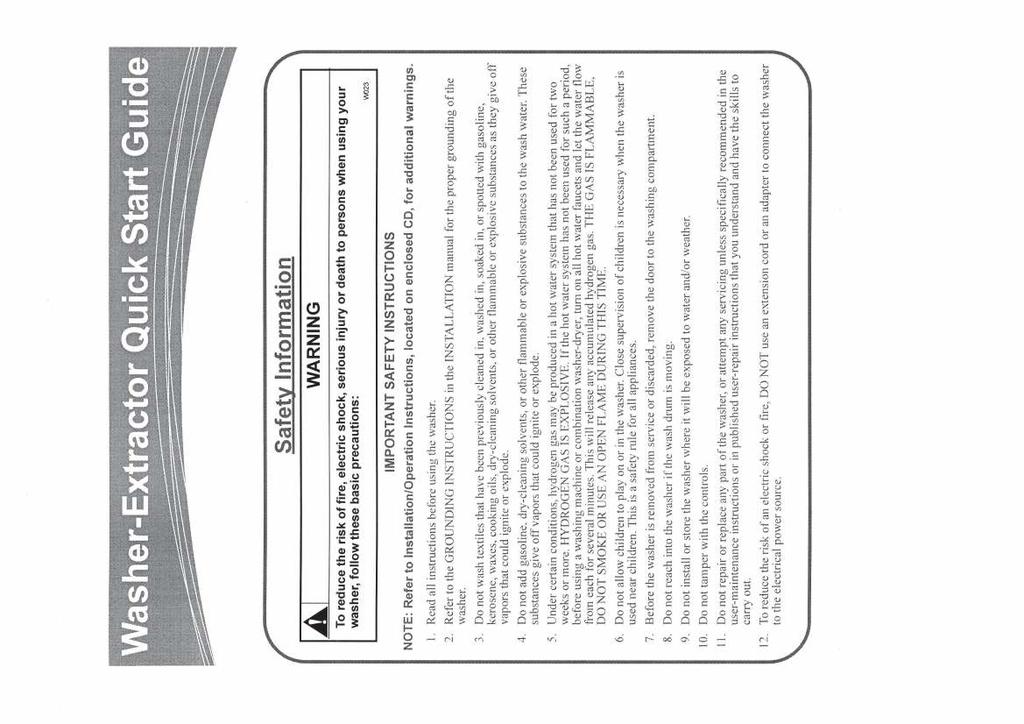
10 2 Important Safety Instructions WARNING To reduce the risk of fire, electric shock, serious injury or death to persons when using your washer, follow these basic precautions: Read all instructions before using the washer. Refer to the GROUNDING INSTRUCTIONS in the installation Manual for the proper grounding of the washer. Do not wash textiles that have been previously cleaned, washed, soaked, or spotted with gasoline, dry-cleaning solvents, or other flammable or explosive substances as they give off vapors that could ignite or explode. Do not add gasoline, dry-cleaning solvents, or other flammable or explosive substances to the wash water. These substances give off vapors that could ignite or explode. Under certain conditions, hydrogen gas may be produced in a hot water system that has not been used for two weeks or more. HYDROGEN GAS IS EXPLOSIVE. If the hot water system has not been used for such a period, before using a washing machine or combination washer-dryer, turn on all hot water faucets and let the water flow from each for several minutes. This will release any accumulated hydrogen gas. The gas is flammable, do not smoke or use an open flame during this time. Do not allow children to play on or in the washer. This appliance is not intended for use by young children or infirm persons without supervision. Young children should be supervised to ensure that they do not play with the appliance. Before the washer is removed from service or discarded, remove the door to the washing compartment. Do not reach into the washer if the wash drum is moving. This is an imminently hazardous situation that, if not avoided, will cause severe personal injury or death. Do not install or store the washer where it will be exposed to water and/or weather. 10. Do not tamper with the controls. 11. Do not repair or replace any part of the washer, or attempt any servicing unless specifically recommended in the user-maintenance instructions or in published user-repair instructions that the user understands and has the skills to carry out. 12. To reduce the risk of an electric shock or fire, DO NOT use an extension cord or an adapter to connect the washer to an electrical power source. 13. Use a washer only for its intended purpose, washing textiles. 14. ALWAYS disconnect the washer from the electrical supply before attempting any service. Disconnect the power cord by grasping the plug, not the cord. 15. Install the washer according to the INSTALLATION INSTRUCTIONS. All connections for water, drain, electrical power and grounding must comply with local codes and be made by licensed personnel when required. 16. To reduce the risk of fire, textiles which have traces of any flammable substances such as vegetable oil, cooking oil, machine oil, flammable chemicals, thinner, etc., or anything containing wax or chemicals such as in mops and cleaning cloths, must not be put into the washer. These flammable substances may cause the fabric to catch on fire. 17. Do not use fabric softeners or products to eliminate static unless recommended by the manufacturer of the fabric softener or product. 18. Keep washer in good condition. Bumping or dropping the washer can damage safety features. If this occurs, have washer checked by a qualified service person. 19. Replace worn power cords and/or loose plugs. 20. Be sure water connections have a shut-off valve and that fill hose connections are tight. CLOSE the shut-off valves at the end of each wash day.
11 2 21. Loading door MUST BE CLOSED any time the washer is to fill, tumble, or spin. DO NOT bypass the loading door switch by permitting the washer to operate with the loading door open. 22. Always read and follow manufacturer s instructions on packages of laundry and cleaning aids. Heed all warnings or precautions. To reduce the risk of poisoning or chemical burns, keep them out of the reach of children at all times (preferably in a locked cabinet). 23. Always follow the fabric care instructions supplied by the textile manufacturer. 24. Never operate the washer with any guards and/or panels removed. 25. DO NOT operate the washer with missing or broken parts. 26. DO NOT bypass any safety devices. 27. Failure to install, maintain, and/or operate this washer according to the manufacturer s instructions may result in conditions which can produce bodily injury and/or property damage. 28. It is recommended that the machine be installed by qualified technicians. 29. Before starting repairs or maintenance, shut off all power and water supplies. 30. To prevent fire and explosion: Keep the area around the machine free from inflammable or combustible products. NOTE: The WARNINGS and IMPORTANT SAFETY INSTRUCTIONS appearing in this manual are not meant to cover all possible conditions and situations that may occur. Common sense, caution, and care must be exercised when installing, maintaining, or operating the washer. Any problems or conditions not understood should be reported to the dealer, distributor, service agent, or the manufacturer. SAVE THESE INSTRUCTIONS
12 2 Operator Safety WARNING NEVER insert hands or objects into basket until it has completely stopped. Doing so could result in serious injury. To ensure the safety of machine operators, the following maintenance checks must be performed daily: 1. Prior to operating the machine, verify that all warning signs are present and legible. Missing or illegible signs must be replaced immediately. Make certain that spares are available. 2. Check door interlock before starting operation of the machine: a. Attempt to start the machine with the door open. The machine should not start with the door open. b. Close the door without locking it and attempt to start the machine. The machine should not start with the door unlocked. c. Close and lock the door and start a cycle. Attempt to open the door while the cycle is in progress. The door should not open. If the door lock and interlock are not functioning properly, call a service technician. 3. Do not attempt to operate the machine if any of the following conditions are present: a. The door does not remain securely locked during the entire cycle. b. Excessively high water level is evident. c. Machine is not connected to a properly grounded circuit. Do not bypass any safety devices in the machine. WARNING Never operate the machine with a bypassed or disconnected balance system. Operating the machine with severe out-of-balance loads could result in personal injury and serious equipment damage. SAVE THESE INSTRUCTIONS
13 3 Technical data W121E METRIC US Capacity (dry weight) Ratio [kg/lit] 1:11 12 kg lb. 1:10 13,2 kg lb. 1:9 14,5 kg lb. Cylinder Diameter 650 mm inch Depth 400 mm inch Volume 132 Lit 4.66 ft³ Cabinet Height 1204 mm inch Width 780 mm inch Depth 842 mm inch Front loading Diameter door opening 300 mm inch Door height 455 mm inch To center 606 mm inch Speed Wash tr/min - RPM Distribution 85 tr/min - RPM Spin 475 tr/min - RPM G-factor Motor (3-phase) Drain valve Water supply Steam connection Heating Packing dimensions Weight Spin 82 4p tr./min 0,75kW / 1HP 2" Hard, soft, warm water 3/4" Steam connection 3/8" Electrical 230/400 V 12 kw - 15 kw - 18 kw Electrical 400V N/A Steam X Warm water (without additional heating) X Warm water (with additional heating) X (H x W x D) mm - inch 1340x 848x 950 mm x33.38x37.40 inch Net 280 kg lb. Gross 293 kg lb.
14 3 Dimensions W121E Legend: metric mm [inches] 84 [3.31] 220 [8.66] 332 [13.07] 267 [10.51] 202 [7.95] [4.19] 455 [17.91] 1204 [47.4] 1175 [46.26] 70 [2.76] 640 [25.2] 70 [2.76] 780 [30.71] 28 [1.1] 260 [10.24] 410 [16.14] 760 [29.92] 82 [3.23] 816 [32.12] 33 [1.3] A 969 [38.15] 936 [36.85] 894 [35.2] B C D E I 109 [4.29] F G 843 [33.19] A. Ventilation soap dispenser B. Liquid soap connections C. Hard water connections 3/4" D. Warm water connections 3/4" E. Soft water connections 3/4" F. Main switch G.Electrical connections I. Ventilation tub K. Drain valve L. Steam connections L 302 [11.89] K 315 [12.4] 209 [8.23] 84 [3.31]
15 3 Technical data W151E METRIC US Capacity (dry weight) Ratio [kg/lit] 1:11 15 kg lb. 1:10 16,5 kg lb. 1:9 18,3 kg lb. Cylinder Diameter 650 mm inch Depth 500 mm inch Volume 165 Lit 5.82 ft³ Cabinet Height 1204 mm inch Width 780 mm inch Depth 942 mm inch Front loading Diameter door opening 300 mm inch Door height 455 mm inch To center 606 mm inch Speed Wash tr/min - RPM Distribution 85 tr/min - RPM Spin 475 tr/min - RPM G-factor Motor (3-phase) Drain valve Water supply Steam connection Heating Packing dimensions Weight Spin 82 4p tr./min 0,75kW / 1HP 2" Hard, soft, warm water 3/4" Steam connection 3/8" Electrical 230/400 V 12 kw - 15kW - 18 kw Electrical 400V 21 kw - 24 kw Steam X Warm water (without additional heating) X Warm water (with additional heating) X (H x W x D) mm - inch 1340x848x1020 mm x33.38x40.15 inch Net 298 kg lb. Gross 310 kg lb.
16 3 Dimensions W151E Legend: metric mm [inches] 84 [3.31] 220 [8.66] 28 [1.1] 260 [10.24] 510 [20.08] 33 [1.3] [33.86] 455 [17.91] 1204 [47.4] 1175 [46.26] 70 [2.76] 640 [25.2] 70 [2.76] 780 [30.71] 82 [3.23] [36.07] 202 [7.95] 332 [13.07] 267 [10.51] [4.19] A 969 [38.15] 936 [36.85] 894 [35.2] B C D E I 109 [4.29] F G 843 [33.19] A. Ventilation soap dispenser B. Liquid soap connections C. Hard water connections 3/4" D. Warm water connections 3/4" E. Soft water connections 3/4" F. Main switch G.Electrical connections I. Ventilation tub K. Drain valve L. Steam connections L 302 [11.89] K 315 [12.4] 209 [8.23] 84 [3.31]
17 Installation and Connection Instructions CAUTION 4 Ensure that the machine is installed on a level floor of sufficient strength and that the recommended clearances for inspection and maintenance are provided. Never allow the inspection and maintenance space to be blocked. A Label 1 A Surface The machine must be securely fixed on a flat surface (metal base, concrete or solid ground). The anchoring is to be done on the 4 provided places (A) (See Label 1) in the holes on the corner of the base. (See Mounting Bolt Hole Locations) The machine must be placed entirely level. For easy maintenance it is recommended to keep a minimal distance of 600 mm inch between the wall and the back of the machine. If several machines are placed next to each another, there should be a minimal distance of 30 mm inch between each machine. E F D C Anchoring on a metal base The machines must be fixed on a metal base which is securely anchored on a concrete base. See Label 2. D B A C G A: Bolt M16 (5/8 ) B: Concrete base 35 cm C: Washer 40x17x4 (1.57x0.60x0.15) D: Nut M16 (5/8 ) E: Base of the machine F: Metal base G: Bolt M16x60 (5/8 x 2 1/2 ) Label 2 Directly on the ground E B D C The machine must be anchored directly on a concrete base. See Label 3. A: Bolt M16 (5/8 ) B: Concrete base 35 cm C: Washer 40x17x4 (1.57x0.60x0.15) D: Nut M16 (5/8 ) E: Base of the machine A IMPORTANT: Machine bolts should be re-checked on a quarterly basis. Label 3
18 4 Mounting Bolt Hole Locations for machine W121E Legend: metric mm [inches] Ø22 [Ø0.87] 33 [1.3] 410 [16.14] 260 [10.24] 28 [1.1] 670 [26.38] 731 [28.78] 70 [2.76] 640 [25.2] 70 [2.76] 780 [30.71]
19 4 Mounting Bolt Hole Locations for machine W151E Legend: metric mm [inches] Ø22 [Ø0.87] 33 [1.3] 510 [20.08] 770 [30.31] 831 [32.72] 260 [10.24] 28 [1.1] 70 [2.76] 640 [25.2] 70 [2.76] 780 [30.71]
20 Water connection 4 The machine is delivered with hoses with 3/4" connections. These hoses fit the water inlet valves of the machine and the main water inlet taps. To ensure the optimal functioning of the water inlet valves, the water pressure on the inlet should be between 2.07 and 5.86 bar (30 and 85 psi). If the pressure is too low, the cycle time will increase considerably. In case of boiler fed machines, a minimum of hot water of 90 C F should be available per unit. (See Table 1) MODEL Min Contents Boiler METRIC For the W121 E 100L 3.53 ft³ For the W L 4.23 ft³ Please connect BOTH water inlets. If you have no warm water connection, please connect BOTH to cold water!!! Table 1 US Water drain The machine is equipped with a drain valve with 2" outer diameter (50 mm). This drain valve should be connected to the drain by means of the drain elbow which is delivered with the machine. The diameter of the main drain should be adapted to the water flow and the number of machines. It should be sufficient to handle at least 80 l/min gal./min per machine. It is necessary to connect the main drain at least on one side to an open air-brake to allow ventilation.
21 4 Electrical Installation Important Electrical ratings are subject to changes. Refer to serial plate decal for electrical ratings information specific to your machine. WARNING Hazardous Voltage. Can cause shock, burn or cause death. Allow machine power to remain off for two minutes prior to working in and around AC inverter drive. WARNING Hazardous Voltage. Can cause shock, burn or death. Verify that a ground wire from a proven earth ground is connected to the lug near the input power block on this machine. The AC inverter drive requires a clean power supply free from voltage spikes and surges. If a transformer or generator is connected to the building's power supply, always install line reactors before the terminal block connections to the machine. A voltage monitor should be used to check incoming power. The customer s local power company may provide such a monitor. If input voltage measures above 240V for a 220V drive or above 480V for a 400V drive, ask the power company to lower the voltage. As an alternative, a step-down transformer kit is available from the distributor. The AC drive provides overload protection for the drive motor. However, a separate single or three-phase circuit breaker must be installed for complete electrical overload protection. This prevents damage to the motor by disconnecting all legs if one should be lost accidentally. Check the data plate on the back of the washer-extractor or consult Table 2 through 7 for circuit breaker requirements. IMPORTANT: Do NOT use fuses in place of a circuit breaker. For installation in the United States or Canada, branch circuit protection must be provided according to National and Local Codes. The branch circuit breaker must be of the inverse time or instantaneous trip type at the values given in the technical specifications for each machine. Use a circuit breaker of the minimal type of 10kA interrupt current. CAUTION Do not use a voltage or phase converter on any variable speed machine. The washer-extractor should be connected to an individual branch circuit not shared with lighting or another electrical device. - In accordance with legal regulations, every machine must be protected with an earth leakage circuit breaker of 30mA. - The earth leakage circuit breaker, which one uses, must be of the type SI. - For countries outside the European Community, the usual safety instructions must be observed.
22 4 The connection should be shielded in a liquid tight or approved flexible conduit with proper conductors of correct size installed in accordance with the National Electric Code or other applicable codes. The connection must be made by a qualified electrician using the wiring diagram provided with the washer-extractor, or according to accepted European standards for CE-approved equipment. Use wire sizes indicated in Table 2 through 7 for runs up to 50 feet. Use next larger size for runs of 50 to 100 feet. Use two sizes larger for runs greater than 100 feet. For personal safety and proper operation, the washer-extractor must be grounded in accordance with state and local standards. If such standards are not available, grounding must conform to the National Electric Code, article The ground connection must be made to a proven earth ground, not to a water pipe, gas pipe, or another metal pipe. Provide the necessary equipotential connections according to the local electrical prescriptions. GROUNDING INSTRUCTIONS This appliance must be connected to a grounded metal, permanent wiring system; or an equipmentgrounding conductor must be run with the circuit conductors and connected to the equipmentgrounding terminal or lead on the appliance. IMPORTANT: Laundry Systems Warranty does not cover components that fail as a result of improper input voltage.
.")
23 4 Main power connection Label 4 Connection label: Machine power connections are made at the back of the machine. Three or four conductor power cable is the recommended method (See chapter electrical specs for minimum cable requirements, if local electrical codes exceed these requirements, follow local codes). The number of conductors in this cable and the proper connection points for the cable wires shall be determined by the machine and power requirements. All machines must have a ground wire and be properly grounded. The ground wire must be insulated with a green/yellow color. This wire is normally within the power cable but can also be a separate wire run along side the power cable if properly sized. Never run a machine that does not have a ground wire. This ground wire must be connected to the machine grounding lug found near the main switch. This lug is identified with the international protective earth symbol and the letters PE. Failure to connect this ground wire can lead to an unsafe machine condition leading to machine damage and/or operator injury or death. This wire must be connected to earth ground at far end. Machine Power Cable Connections: Remove main switch cover plate at back of machine (see chapter dimensions part (F)). Run power cable through the cabinet knock-out located directly below the cover plate. Before installing, obtain and install a cord-grip to hold the cable in place. Never rely upon the electrical connections to hold cable in place. Allow some slack in this cable outside of the machine to form a drip-loop between the supply power circuit breaker and the machine knock-out. Connect power cable wires as directed below. Always connect the ground wire first and remove last. Wiring based on the supply power and machine design (voltage/frequency): Volts, 3-Phase, 3-wire or 4-wire + PE, 50 or 60 Hertz Configuration (Named: N-Voltage): With supply power of: Volts, 3-phase, 3-wire, after connecting the green/yellow PE ground wire, connect one wire to each of the bottom terminals of the power contactor switch marked: L1,L2,L3. When this supply power has four wires, connect this 4th wire, identified as a neutral wire, to the bottom terminal of the auxiliary contactor on the power contactor switch marked: N. Connect the remaining power wires as first noted Volts, 3-Phase, 4-wire + PE, 50 or 60 Hertz Configuration (Named: P-Voltage): With supply power of: Volts, 3-phase, 4-wire, after connecting the green/yellow PE ground wire, follow the directions of the four wire system for Volt configuration.
24 Volts, 3-Phase, 3-wire + PE, 50 or 60 Hertz Configuration (Named: Q-Voltage or 3-phase X-Voltage): With supply power of: Volts, 3-phase, 3-wire, after connecting the green/yellow PE ground wire, connect one power wire to each of the terminals at the bottom of the power contactor switch marked: L1,L2,L volts, 1-Phase, 2-wire + PE, 50 Hertz (called 1-phase, 50 Hz X-voltage): With supply power of: Volts, 1-phase, 2-wire, 50Hz, after connecting the green/yellow PE ground wire, connect the power wire to the L1 bottom terminal of the power contactor switch and the other wire, identified as the neutral wire, to the bottom terminal of the auxiliary contactor on the power contactor switch marked: N volts, 1-Phase, 2-wire + PE, 60 Hertz (called 1-phase, 60 Hz X-voltage): With supply power of: Volts, 1-phase, 2-wire, 60Hz, after connecting the green/yellow PE ground wire, connect one power wire to the L1 and power wire to the L2 of the bottom terminals of the power contactor switch. After connection, check the spin direction. The cylinder must spin in the clockwise direction. A wrong spin direction can damage the motor and can also cause water to spurt from the soap dispenser. In case of wrong spin direction: switch the terminal clamps of the motor circuit R and S of the connecting cable or change the connection at the terminal block switching the L1 and L2 wires.
25 4 WARNING The washer-extractor should be connected to an individual branch circuit not shared with lighting or other equipment. Electrical Specifications W121E 135 liters / 30 pounds Boiler Fed/Steam Heat Electric Heat AWG/mm2 Recommended Circuit Breaker (USmarket) Full Load Amps kw Standard Heating Elements AWG/mm2 Recommended Circuit Breaker (US-market) Full Load Amps Wire Phase Cycle Voltage Code US NON-US US NON-US N / PE / /6.0 P / N+PE / /10.0 6x2 kw Q / PE / /10.0 X /60 1/3 2/3+PE /2.5 N/A N/A N/A N/A Alternative Electric Heat Options N / PE /6.0 P / N+PE 3x3 kw /10.0 Q / PE 3x2 kw /16.0 X /60 1/3 2/3+PE N/A N/A N/A N/A N / PE /10.0 P / N+PE /10.0 6x3 kw Q / PE /25.0 X /60 1/3 2/3+PE N/A N/A N/A N/A Table 5
26 4 WARNING The washer-extractor should be connected to an individual branch circuit not shared with lighting or other equipment. Electrical Specifications W151E 165 liters / 35 pounds Boiler Fed/Steam Heat Electric Heat AWG/mm2 Recommended Circuit Breaker (USmarket) Full Load Amps kw Standard Heating Elements AWG/mm2 Recommended Circuit Breaker (US-market) Full Load Amps Wire Phase Cycle Voltage Code US NON-US US NON-US N / PE / /10.0 P / N+PE / /10.0 6x3 kw Q / PE / /25.0 X /60 1/3 2/3+PE /2.5 N/A N/A N/A N/A Alternative Electric Heat Options N / PE /6.0 P / N+PE 3x3 kw /10.0 Q / PE 3x2 kw /16.0 X /60 1/3 2/3+PE N/A N/A N/A N/A N / PE /10.0 P / N+PE 3x3 kw /16.0 Q / PE 3x4 kw N/A N/A N/A N/A X /60 1/3 2/3+PE N/A N/A N/A N/A N / PE /6.0 P / N+PE /10.0 6x2 kw Q / PE /10.0 X /60 1/3 2/3+PE N/A N/A N/A N/A N / PE /10.0 P / N+PE /16.0 6x4 kw Q / PE N/A N/A N/A N/A X /60 1/3 2/3+PE N/A N/A N/A N/A Table 6
27 4 Liquid soap connection (option) Connection of the liquid soap hoses The liquid soap connection consists of 8 connections for liquid soap (See Label 5). The central opening is used for ventilation. WARNING Label 5 Dangerous Chemicals. May damage eyes and skin. Wear eye and hand protection when handling chemicals; always avoid direct contact with raw chemicals. Read the manufacturer s directions for accidental contact before handling chemicals. Ensure an eye-rinse facility and an emergency shower are within easy reach. Check at regular intervals for chemical leaks. CAUTION Drill out plugs and nipples before making supply hose connection. Failure to do so can cause buildup of pressure and risk a tubing rupture. Electrical connection of the liquid soap pumps On machines equipped with a liquid soap connection, connect the wires directly on the print board next to the ground wire connection (option). Connect as indicated on the wiring diagram. The two connectors on the right give a tension of 220V ~ (max. 4A) which can be applied to drive 220V ~ soap pumps. If more than 4A is required, an external tension will have to be used. 6 connections have been provided, of which one (S6) can be used to drive a waterproofing pump (e.g. for rain coats, etc.). (See Label 6) Label 6 2
28 4 The 220V can be transformed to other values to drive other type soap pumps. Example: pumps 24V ~. (See Label 7) Label 7 Also, pumps with different operating tension can be combined. Example: 5 pumps 220V ~ and 1 pump 24V ~. (See Label 8) Label 8 With an external tension 24V DC (See Label 9) Label 9 3
29 4 Connection of a central operating panel for coin machines (option) WARNING To reduce the risk of electric shock, disconnect this appliance from the power supply before attempting any user maintenance. Turning the controls to the OFF position does not disconnect this appliance from the power supply. At the backside above the main connectors, you find a printboard, to which the central operating panel for coin machines can be connected. The right connectors form a potential free output contact as a result of which the operating panel detects when the machine is activated or not. The left connectors receive the signal, by means of which a machine is chosen through the operating panel. There are 3 different variations possible according to the output voltage of the operating panel. (See Labels 10, 11 and 12) Label 10 Label 11 Label 12 A IMPORTANT: If a machine is equipped with this kind of printboard or if a printboard has been built in, the resistance of the cycle contact (A) may no longer be present on the main printboard. (See Label 13) When this resistance is present, it has to be cut out of the main printboard. Label 13 4
30 Steam connection 5 WARNING Never touch internal or external steam pipes, connections, or components. These surfaces can be extremely hot and will cause severe burns. The steam must be turned off and the pipe, connections, and components allowed to cool before the pipe can be touched. Machines with steam heating must have a steam valve between the steam installation and the machine With direct steam injection into the machine (See Table 7) 1. Steam pipe 2. Steam cut-off valve 3. Pipe coupling 4. Steam filter 5. Magnetic steam valve 6. Curve MF 7. Steam hose with appropriate pipe coupling 7 Steam Supply Information MODEL Steam inlet connection, inch Number of steam inlets Recommended pressure, bar Recommended pressure, psi Maximum pressure, bar Maximum pressure, psi For the W121E WF65, IWF065, IWF014, CWF065, CWF01 3/ For the W151E WF75, IWF074, IWF018, CWF074 3/ For the WF135 = WF135, IWF135, IWF030, CWF135, CWF030 3/ For the WF165 = WF165, IWF165, CWF165, CWF035 3/ Table 7 5
31 4 WARNING The washer-extractor should be connected to an individual branch circuit not shared with lighting or other equipment. Electrical Specifications W151E 165 liters / 35 pounds Boiler Fed/Steam Heat Electric Heat AWG/mm2 Recommended Circuit Breaker (USmarket) Full Load Amps kw Standard Heating Elements AWG/mm2 Recommended Circuit Breaker (US-market) Full Load Amps Wire Phase Cycle Voltage Code US NON-US US NON-US N / PE / /10.0 P / N+PE / /10.0 6x3 kw Q / PE / /25.0 X /60 1/3 2/3+PE /2.5 N/A N/A N/A N/A Alternative Electric Heat Options N / PE /6.0 P / N+PE 3x3 kw /10.0 Q / PE 3x2 kw /16.0 X /60 1/3 2/3+PE N/A N/A N/A N/A N / PE /10.0 P / N+PE 3x3 kw /16.0 Q / PE 3x4 kw N/A N/A N/A N/A X /60 1/3 2/3+PE N/A N/A N/A N/A N / PE /6.0 P / N+PE /10.0 6x2 kw Q / PE /10.0 X /60 1/3 2/3+PE N/A N/A N/A N/A N / PE /10.0 P / N+PE /16.0 6x4 kw Q / PE N/A N/A N/A N/A X /60 1/3 2/3+PE N/A N/A N/A N/A Table 6
32 Maintenance instruction of the machine 7 WARNING To reduce the risk of electric shock, disconnect this appliance from the power supply before attempting any user maintenance. Turning the controls to the OFF position does not disconnect this appliance from the power supply. End of day Clean AC drive filter: a. Snap off external plastic cover which contains filter. b. Remove foam filter from cover. c. Wash filter with warm water and allow to air dry. Filter can be vacuumed clean. General maintenance Clean the entire cabinet of the machine regularly and remove all traces of soap, etc... Remove all detergent residue in the soap dispenser with hot water. Clean the door gasket and remove all detergents and other products. Shut off the main water, steam, and power connections at the end of each day. Do not change the setting of the water inlet taps on boiler fed machines once these have been installed. It is recommended to leave the door and soap dispenser open after use, to ventilate the machine. Check for proper door lock operation on a daily basis. Periodical maintenance The V-belts of the motors should be retightened after two to three months when first used. This is necessary because these belts are subject to a one-time stretching when first used. If this is not done, the belt starts to slip after a few months and will break shortly afterwards. Check the water inlet filters to make sure they are not blocked by calcification. Check the drain valve for obstructions. If a machine frequently skips the final spin, check whether the probe of the out of balance switch is still in the appropriate position, that is horizontally centered and vertically 1/3 from the bottom inside the window. (When the drum is empty). Important B - Clean the drainpipe every 6 months in case drain (B) is used. - The water still being in the drain needs to be drained using drain (A) before cleaning the drainpipe or replacing the exhaust valve. A Label 16
33 Contact Information 8 Nameplate Nameplate Location The nameplate is located at the rear of the machine. Always provide the machine s serial number and model number when ordering parts or when seeking technical assistance. Label 16 Label 17 8
34 9 Repair and after-sales service In case of important malfunctions and deficiencies, which you cannot resolve yourself, contact your distributor. Distributor : Name:... Address:... Tel.:... Machine : Type:... Program:... Date of installation:... Installed by:... Serial number:... Operation voltage and frequency:...
35 Operating instructions electronic timer micro 20 Manual
36 Contents 1 Safety and Environmental Informations...4 Safety...4 Environmental...5 Explanation of Safety Messages... 6 Important Safety Instructions...7 Operator Safety Operating instructions...12 Machine with start button...12 Machine with coin or token operation Standard programs Error messages Contact Information...29 Nameplate Repair and after-sales service...31 Contents 3
37 Safety and Environmental Informations 1 Safety CAUTION LABELS Please familiarize yourself with the following standard warning symbols. They are used throughout this manual and on the equipment to alert you to possible hazards. Anyone operating or servicing this equipment must understand these symbols and must follow all safety rules in this manual. ELECTRICAL HAZARD This symbol alerts you to the presence of a dangerous voltage, which could cause a serious shock resulting in personal injury or death. CONSULT MANUAL This symbol warns you to consult the manual for important instructions concerning the machine and possible hazards. MOVING PARTS HAZARD This symbol alerts you to the presence of possible dangerous moving parts within the machine. Guards should always be in place when the machine is in operation. Be very careful when servicing the drive system. PINCHING HAZARD This warning symbol indicates the presence of a pinch point on the machine. This is a place where your hand might be pinched or crushed, resulting in a severe injury. Make sure you understand these hazards and keep all body parts clear of them. HOT SURFACE HAZARD This symbol indicates the presence of a potentially hot surface. Some machine surfaces and parts may become extremely hot during normal operation and should not be touched. ATTENTION This symbol identifies information about practices or circumstances that can lead to personal injury or death, property damage, or economic loss. 4
38 1 Environmental Disposal of Unit This appliance is marked according to the European directive 2002/96/ EC on Waste Electrical and Electronic Equipment (WEEE). This symbol on the product or on its packaging indicates that this product shall not be treated as household waste. Instead it shall be handed over to the applicable collection point for the recycling of electrical and electronic equipment. Ensuring this product is disposed of correctly, you will help prevent potential negative consequences for the environment and human health, which could otherwise be caused by inappropriate waste handling of this product. The recycling of materials will help to conserve natural resources. For more detailed information about recycling of this product, please contact your local distributor resources. 5
39 1 Explanation of Safety Messages Throughout this manual and on machine decals, you will find precautionary statements ( DANGER, WARNING, and CAUTION ) followed by specific instructions. These precautions are intended for the personal safety of the operator, user, servicer, and those maintaining the machine. DANGER Indicates an imminently hazardous situation that, if not avoided, will cause severe personal injury or death. WARNING Indicates a hazardous situation that, if not avoided, could cause severe personal injury or death. CAUTION Indicates a hazardous situation that, if not avoided, may cause minor or moderate personal injury or property damage. Additional precautionary statements ( IMPORTANT and NOTE ) are followed by specific instructions. IMPORTANT: The word IMPORTANT is used to inform the reader of specific procedures where minor machine damage will occur if the procedure is not followed. NOTE: The word NOTE is used to communicate installation, operation, maintenance or servicing information that is important but not hazard related. 6
40 1 Important Safety Instructions WARNING To reduce the risk of fire, electric shock, serious injury or death to persons when using your washer, follow these basic precautions: Read all instructions before using the washer. Refer to the GROUNDING INSTRUCTIONS in the installation Manual for the proper grounding of the washer. Do not wash textiles that have been previously cleaned, washed, soaked, or spotted with gasoline, dry-cleaning solvents, or other flammable or explosive substances as they give off vapors that could ignite or explode. Do not add gasoline, dry-cleaning solvents, or other flammable or explosive substances to the wash water. These substances give off vapors that could ignite or explode. Under certain conditions, hydrogen gas may be produced in a hot water system that has not been used for two weeks or more. HYDROGEN GAS IS EXPLOSIVE. If the hot water system has not been used for such a period, before using a washing machine or combination washer-dryer, turn on all hot water faucets and let the water flow from each for several minutes. This will release any accumulated hydrogen gas. The gas is flammable, do not smoke or use an open flame during this time. Do not allow children to play on or in the washer. This appliance is not intended for use by young children or infirm persons without supervision. Young children should be supervised to ensure that they do not play with the appliance. Before the washer is removed from service or discarded, remove the door to the washing compartment. Do not reach into the washer if the wash drum is moving. This is an imminently hazardous situation that, if not avoided, will cause severe personal injury or death. Do not install or store the washer where it will be exposed to water and/or weather. 10. Do not tamper with the controls. 11. Do not repair or replace any part of the washer, or attempt any servicing unless specifically recommended in the user-maintenance instructions or in published user-repair instructions that the user understands and has the skills to carry out. 12. To reduce the risk of an electric shock or fire, DO NOT use an extension cord or an adapter to connect the washer to an electrical power source. 13. Use a washer only for its intended purpose, washing textiles. 14. ALWAYS disconnect the washer from the electrical supply before attempting any service. Disconnect the power cord by grasping the plug, not the cord. 15. Install the washer according to the INSTALLATION INSTRUCTIONS. All connections for water, drain, electrical power and grounding must comply with local codes and be made by licensed personnel when required. 16. To reduce the risk of fire, textiles which have traces of any flammable substances such as vegetable oil, cooking oil, machine oil, flammable chemicals, thinner, etc., or anything containing wax or chemicals such as in mops and cleaning cloths, must not be put into the washer. These flammable substances may cause the fabric to catch on fire. 17. Do not use fabric softeners or products to eliminate static unless recommended by the manufacturer of the fabric softener or product. 18. Keep washer in good condition. Bumping or dropping the washer can damage safety features. If this occurs, have washer checked by a qualified service person. 19. Replace worn power cords and/or loose plugs. 20. Be sure water connections have a shut-off valve and that fill hose connections are tight. CLOSE the shut-off valves at the end of each wash day. 7
41 1 21. Loading door MUST BE CLOSED any time the washer is to fill, tumble, or spin. DO NOT bypass the loading door switch by permitting the washer to operate with the loading door open. 22. Always read and follow manufacturer s instructions on packages of laundry and cleaning aids. Heed all warnings or precautions. To reduce the risk of poisoning or chemical burns, keep them out of the reach of children at all times (preferably in a locked cabinet). 23. Always follow the fabric care instructions supplied by the textile manufacturer. 24. Never operate the washer with any guards and/or panels removed. 25. DO NOT operate the washer with missing or broken parts. 26. DO NOT bypass any safety devices. 27. Failure to install, maintain, and/or operate this washer according to the manufacturer s instructions may result in conditions which can produce bodily injury and/or property damage. 28. It is recommended that the machine be installed by qualified technicians. 29. Before starting repairs or maintenance, shut off all power and water supplies. 30. To prevent fire and explosion: Keep the area around the machine free from inflammable or combustible products. NOTE: The WARNINGS and IMPORTANT SAFETY INSTRUCTIONS appearing in this manual are not meant to cover all possible conditions and situations that may occur. Common sense, caution, and care must be exercised when installing, maintaining, or operating the washer. Any problems or conditions not understood should be reported to the dealer, distributor, service agent, or the manufacturer. SAVE THESE INSTRUCTIONS 8
42 1 Operator Safety WARNING NEVER insert hands or objects into basket until it has completely stopped. Doing so could result in serious injury. To ensure the safety of machine operators, the following maintenance checks must be performed daily: 1. Prior to operating the machine, verify that all warning signs are present and legible. Missing or illegible signs must be replaced immediately. Make certain that spares are available. 2. Check door interlock before starting operation of the machine: a. Attempt to start the machine with the door open. The machine should not start with the door open. b. Close and lock the door and start a cycle. Attempt to open the door while the cycle is in progress. The door should not open. If the door lock and interlock are not functioning properly, call a service technician. 3. Do not attempt to operate the machine if any of the following conditions are present: a. The door does not remain securely locked during the entire cycle. b. Excessively high water level is evident. c. Machine is not connected to a properly grounded circuit. Do not bypass any safety devices in the machine. WARNING Never operate the machine with a bypassed or disconnected balance system. Operating the machine with severe out-of-balance loads could result in personal injury and serious equipment damage. SAVE THESE INSTRUCTIONS 9
43 10 1
44 11
45 Operating instructions 2 Machine with start button Opening the door Open the door. Fill the drum Close the door Select program Sort the linen according to the type and required temperature of the linen. Empty all pockets of the garments so that no garments can be damaged and no left articles can cause damage to the machine. Turn sleeves of shirts, blouses inside out. It is recommended to mix small and large items to enhance the drop of the linen during the wash cycle and hence improve the wash quality. Wash loads of below 80% of machine capacity can obstruct the proper functioning of the machine and can damage the machine. Overloading the machine can also lead to a bad wash result. Close the door On machines with a start button, the programmer can contain up to 100 programs (0-99). The program number is displayed on the right display. By pressing the SELECT button (P), the next program will be displayed. By pressing the ECO button (E), the previous program will be displayed. By keeping this button pressed, this function will be accelerated. I Remark Select program 0 by keeping the SELECT button pressed continuously for more than 5 seconds. Add detergent It is recommended to only use detergents with a foam-breaker. These are often found in the launderette or laundry or can easily be found in retail stores. Recommended doses are mentioned on the detergent packing. Overdosing of detergents can lead to reduced wash results and overfoaming which can damage the machine. Left compartment A: Central compartment B: Right compartment C: Bottom compartment D: Prewash (1st wash) Main wash (2nd wash) Final rinse (fabric softener) Direct access to tub Economy Wash I Moderately soiled linen can be washed using the Economy Wash function, which reduces the water level of washes and rinses by 20%, allowing savings of water and energy. Press the ECO button during the wash cycle to activate the economy wash function. The ECO LED will light up. At the end of the program the ECO function will be automatically eliminated. If the ECO function is required in the following wash cycle, as well, reactivate this function by repeating the actions described above. 12
46 2 Start the machine Start the wash-cycle by pressing the START button (I) and releasing it immediately. The door is locked and the cycle LED lights up. I During the first 2 minutes after starting, the program number is blinking and you can change the program in case of a possible wrong selection. To do so, select another program with the SELECT button (P). This new program will start immediately. Indications of program sequence Display information The left display will indicate the temperature of the wash bath - in C or F - (on machines where this function has been selected). The central display shows the remaining time to the end of the wash cycle. For programs which are being run for the first time, the machine will take a theoretical time estimate. If this time indication does not correspond to the real cycle time, the cycle time will be corrected from the second cycle onwards (Self-Teaching function of the machine). This correction will have to be preprogrammed and is not activated on program numbers higher than 20. The corrected time will also be lost when the power has been cut from the machine for more than 24 hours. The right display will continue to show the selected program number. If a Level-stop was programmed (which halts the programmer during the filling of the cylinder) and/or a Heat-stop (which stops the programmer during the heating up of the wash bath, then the respective LEDs light up in the display. Once the required water level and/or temperature has been reached, the LED is turned off and the internal programmer advances again. Wash cycle LEDs Each program segment has a corresponding LED. Each of these 6 LEDs light up when the appropriate segment is executed. This way, the program sequence can be accurately followed. When a LED blinks, the machine is taking up water. When a LED blinks slowly, the machine is heating up the water. Spin LEDs When the water is drained at the end of a program segment and the machine spins if so desired, the left spin LED (intermediate spin) will light up together with the cycle LED. - Functioning of the spin LEDs during intermediate spin: Led drain/distribution low spin coast Interm. spin blinking rapidly continuously continuously - Functioning of the spin LEDs during gentle-intermediate spin:. Led drain/distribution low spin coast Interm. spin blinking rapidly blinking slowly blinking slowly 13
47 2 During final spin, both the left spin LED (intermediate spin) will light up together with the right spin LED (final spin). - Functioning of the spin LEDs during final spin: Led drain/distribution low spin high spin coast tumble Interm. spin. blinking rapidly continuously blinking slowly continuously off Final spin continuously continuously blinking slowly continuously blinking rapidly - Functioning of the spin LEDs during gentle-final spin: Led drain/distribution low spin high spin coast tumble Interm. spin blinking rapidly slowly slowly off Final spin continuously continuously continuously rapidly Manual interventions during the program Following functions can be activated during the program: F1 = Time stop To increase the duration of a program segment beyond its originally programmed duration F2 = Soak To soak heavily soiled linen F3 = Reduced wash action To avoid wear of delicate garments F4 = Execute high spin as low spin To avoid creasing delicate linen F5 = Rapid advance To skip certain program segments F6 = No spin To give total protection to delicate garments F7 = on the left display, the number of revolutions of the drum appears F8 = changing the number of revolutions at final spin. In order to limit the rpm for delicate linen Selecting a function 1. Push and hold the SELECT button (P). 2. Push and release the START button (I). 3. Then release the SELECT button (P). I The central display now shows F1 and this function is now active. By pressing the SELECT button (P), the next function will appear on the central display. And so on up to F8. To return to normal operation, press the START button (I) and release. A function is also terminated by selecting another function. Functions are also automatically ended and switched off at the end of each program. 14
W71E - W101E. Manual / Handbuch. Spare parts list / Ersatzteilliste
 W71E - W101E Manual / Handbuch Spare parts list / Ersatzteilliste Equipment Imp.-Exp. GmbH Zitterpappelweg 9 D - 22391 Hamburg Tel.: + 49 40 60009468-0 Fax: + 49 40 536 75 01 E - M a i l : i n f o @ w
IPSO - LSG n.v. Instruction manual WE 55, WE 73, WE 95 WE 110, WE 132, WE 165. With electronical timer µ20
 IPSO - LSG n.v. Instruction manual WE 55, WE 73, WE 95 WE 110, WE 132, WE 165 With electronical timer µ20 Technische gegevens Technical specifications Installation instructions Installatie Operating Gebruiksaanwijzing
Washer-Extractor. Troubleshooting. Cabinet Hardmount Mechanical Timer Refer to Page 8 for Model Numbers.
 Washer-Extractor Cabinet Hardmount Mechanical Timer Refer to Page 8 for Model Numbers Troubleshooting CHM1624C www.comlaundry.com Part No. F232202R3 November 2011 Table of Contents Safety Information...3
Manual / Handbuch Spare parts list / Ersatzteilliste
 Manual / Handbuch Spare parts list / Ersatzteilliste Equipment Imp.-Exp. GmbH Zitterpappelweg 9 D - 22391 Hamburg Tel.: + 49 40 60009468-0 Fax: + 49 40 536 75 01 E - M a i l : i n f o @ w e s c o - n a
Washer-Extractors Pocket Hardmount
 Washer-Extractors Pocket Hardmount Basic Installation/Operation P005I Keep These Instructions for Future Reference. (If this machine changes ownership, this manual must accompany machine.) www.comlaundry.com
Washer-Extractors Cabinet Freestanding Refer to Page 6 for Model Identification
 Washer-Extractors Cabinet Freestanding Refer to Page 6 for Model Identification Installation 33, 40, 55 and 75 Models CFD15C 18, 25 and 35 Models CFD19C CFD19C CFD20C CFD20C 100, 135, 165 and 200 Models
W71E - W101E. Manual / Handbuch. Spare parts list / Ersatzteilliste
 W71E - W101E Manual / Handbuch Spare parts list / Ersatzteilliste Equipment Imp.-Exp. GmbH Zitterpappelweg 9 D - 22391 Hamburg Tel.: + 49 40 60009468-0 Fax: + 49 40 536 75 01 E - M a i l : i n f o @ w
Washer-Extractor. Instructions for Operating the WE-4 and WE-5 Microcomputers COLD / HOT / WARM / LOW HIGH OVER WASH / HEAT / SUPPLY FLUSH RINSE
 Washer-Extractor Pocket Hardmount Instructions for Operating the WE-4 and WE-5 Microcomputers UW50P4 Operation COLD / HOT / WARM / DISPLAY TEMP. / LOW HIGH OVER WASH / HEAT / SUPPLY FLUSH RINSE SOAK MEDIUM
COMMERCIAL WASHERS MODELS T-300/350/400/450/600/650/750/900/950/1200/1450 VENDED C-SERIES CONTROL
 COMMERCIAL WASHERS MODELS T-300/350/400/450/600/650/750/900/950/1200/1450 VENDED C-SERIES CONTROL OPERATOR S MANUAL INSTALLATION & OPERATION INSTRUCTIONS Please read this information and retain for reference.
Washer-Extractors Pocket Hardmount A-Series Microcomputer Variable-Speed
 < < Washer-Extractors Pocket Hardmount A-Series Microcomputer Variable-Speed UW35AV UW60AV UW80AV UW100AV UW125AV Programming 1 2 3 4 5 6 CHM1766C Keep These Instructions for Future Reference. (If this
Washer-Extractors. Installation/Operation/Maintenance. Twin Tub UM202 Design 3 Models
 Washer-Extractors Twin Tub UM202 Design 3 Models Installation/Operation/Maintenance CAR4C_SVG Original Instructions Keep These Instructions for Future Reference. (If this machine changes ownership, this
MODEL T900/950 60LB CAPACITY COMPUTER CONTROL COIN WASHER
 P/N 8514-183-001B MODEL T900/950 60LB CAPACITY COMPUTER CONTROL COIN WASHER DEXTER LAUNDRY, INC. OWNER'S BOOKLET INSTALLATION & OPERATION INSTRUCTIONS Please read this information and retain for reference.
Automatic Washers. Operation. Home Laundry
 Automatic Washers Home Laundry Operation Keep These Instructions for Future Reference. (If this machine changes ownership, this manual must accompany machine.) www.comlaundry.com Part No. R7 August 2007
Washer-Extractors. Installation/Operation/Maintenance. Cabinet Hardmount Refer to Page 8 for Model Identification
 Washer-Extractors Cabinet Hardmount Refer to Page 8 for Model Identification Installation/Operation/Maintenance Original Instructions Keep These Instructions for Future Reference. (If this machine changes
User Manual. Tumble Dryer ZDC8202P
 EN User Manual Tumble Dryer ZDC80P Contents Safety information Safety instructions 3 Product Description 4 Control Panel 5 Programme table 5 Options 6 Settings 7 Before First Use 8 Daily Use 8 Hints and
GB User manual. Washing machine ZWQ 5130
 GB User manual 2 Washing machine ZWQ 5100 ZWQ 5101 ZWQ 5130 Product description 1 1. The control panel 2. Lid handle 3. Adjustable levelling feet 2 3 The control panel 1 2 3 4 5 6 1. Programme selector
Installation Instructions
 Instructions for Frontload Washers Original Instructions Keep These Instructions for Future Reference. (If this machine changes ownership, this manual must accompany machine.) www.alliancelaundry.com Part
Washer-Extractors. Programming. UW Pocket Hardmount B-Series Microcomputer 2 Speed. Models UW35B2 and UW60B2
 < < Washer-Extractors UW Pocket Hardmount B-Series Microcomputer 2 Speed Models UW35B2 and UW60B2 WASH ADD BLEACH RINSE NORMAL HOT LIGHT SOIL HOT PERM PRESS HOT VISA TM WARM Programming SPIN HEAVY SOIL
Washer-Extractors. Cabinet Hardmount A-Series Microcomputer for OPL Models 2 Speed and Variable-Speed Refer to Page 3 for Model Identification
 < < Washer-Extractors Cabinet Hardmount A-Series Microcomputer for OPL Models 2 Speed and Variable-Speed Refer to Page 3 for Model Identification Programming 1 2 3 4 5 6 CHM1766C Keep These Instructions
CONTENTS QUICK REFERENCE GUIDE INSTRUCTIONS FOR USE PROGRAMME CHART BOOKLET
 CONTENTS QUICK REFERENCE GUIDE PROGRAMME CHART PREPARING THE LAUNDRY SELECTING A PROGRAMME AND OPTIONS STARTING AND COMPLETING A PROGRAMME CHANGING A PROGRAMME INTERRUPTING A PROGRAMME DAILY MAINTENANCE
User manual. Washing Machine ZWP 581 ZWQ 5102 ZWQ 5103 ZWQ 5122
 EN User manual Washing Machine ZWP 58 ZWQ 502 ZWQ 503 ZWQ 522 Contents Safety information 2 Product description _ 3 How to run a wash cycle? 4 Daily use _ 5 Washing programmes 6 Care and cleaning 8 Safety
Instructions for Use. Washing Machine
 Instructions for Use Washing Machine Thank you for your confidence in purchasing our washing machine, and congratulations on the excellent choice. Our appliances are friendly to the environment. Your new
User manual. Washing machine ZWQ 590 SO ZWQ 585 SO ZWQ 580 SO ZWQ 575 SO ZWQ 570 SO
 EN User manual Washing machine ZWQ 590 SO ZWQ 585 SO ZWQ 580 SO ZWQ 575 SO ZWQ 570 SO Product description 1 The control panel 2 Lid handle 3 Filter access cover 4 Adjustable levelling feet Control panel
Installation manual W365H, W375H, W3105H, W3130H, W3180H, W3240H, W3300H Exacta & Clarus Control
 manual W365H, W375H, W305H, W330H, W380H, W3240H, W3300H Exacta & Clarus Control 438 9200-0 06.34 Contents 3 Contents Technical data... :... 2: Transportation and unpacking... 2: Siting and floor... 3:
Glass Chimney Hood. Installation & User Instructions Please keep for future reference
 Glass Chimney Hood Installation & User Instructions Please keep for future reference 4897549 4897556 Important Please read these instructions fully before installing or using These instructions contain
Operator s Manual READY RACK EXTRACTOR. Installation/Operation/Maintenance/Parts DIMENSIONS OF THE WASHER: HEIGHT (AT BACK): 42
: 42") READY RACK EXTRACTOR DIMENSIONS OF THE WASHER: HEIGHT (AT BACK): 42 HEIGHT (W/ LID RAISED): 56 WIDTH: 27 DEPTH: 26 DEPTH (W/ REAR HOSE): 30 WEIGHT: 190 lbs. SHIP WEIGHT: 255 lbs. Operator s Manual Installation/Operation/Maintenance/Parts
READY RACK EXTRACTOR DIMENSIONS OF THE WASHER: HEIGHT (AT BACK): 42 HEIGHT (W/ LID RAISED): 56 WIDTH: 27 DEPTH: 26 DEPTH (W/ REAR HOSE): 30 WEIGHT: 190 lbs. SHIP WEIGHT: 255 lbs. Operator s Manual Installation/Operation/Maintenance/Parts
Models Product Information. Important Safety Instructions REV
 Models- 29060-29063 Page 2 - Page 3 - Page 4 - Page 5 - Page 6 7 Page 7-10 Page 10 Page 11 Page 11-12 Page 13-17 Page 18-21 Product Information Specifications Important Safety Instructions Product Dimensions
Installation manual. Tumble dryers T4130. Compass Control
 Installation manual Tumble dryers T4130 Type N1130 Compass Control Installation manual in original language 487 05 41 61/EN 2011.09.16 Contents 3 Contents Safety precautions... 5 Technical data... 7 Setup...
Washer-Extractors. Installation/Operation/Maintenance. Cabinet Freestanding Refer to Page 9 for Model Identification
 Washer-Extractors Cabinet Freestanding Refer to Page 9 for Model Identification Installation/Operation/Maintenance Original Instructions Keep These Instructions for Future Reference. (If this machine changes
Black 8KG 1400 Spin Speed Inverter Direct Drive Washing Machine Instruction Manual
 Black 8KG 1400 Spin Speed Inverter Direct Drive Washing Machine Instruction Manual Model number: RHWM81400DIDB Opening times: Monday - Friday 8am 6pm & Saturday 9am 1pm or visit us at Contents Safety Instructions
Dear Customer, We wish that this product, manufactured at modern facilities with total quality notions, will deliver you the best performance.
 Dear Customer, We wish that this product, manufactured at modern facilities with total quality notions, will deliver you the best performance. In order to guarantee this, please read this instruction manual
Washer-Extractors. Operation/Maintenance. Cygnus Vended, Cygnus Select and Cygnus Ultra Controls. Refer to Page 7 for Model Identification
 Washer-Extractors Cygnus Vended, Cygnus Select and Cygnus Ultra Controls Refer to Page 7 for Model Identification Operation/Maintenance Open door Abra la puerta Prewash Prelavado Hot wash Lavado caliente
Removing shipping locks
 y Safety instructions Scope of delivery Moisture in the drum is due to end inspection. Removing shipping locks Water connection l The washing machine is heavy - lift with caution. Frozen hoses can tear/burst.
Washer-Extractor Cabinet Freestanding
 Washer-Extractor Cabinet Freestanding Refer to Page 3 for Model Numbers Parts CFD22C_D0055 www.comlaundry.com Part No. D0055R3 April 2011 Table of Contents Title Page Parts Ordering Information... 2 Nameplate
Washer-Extractors. Operation/Maintenance. Cabinet Hardmount Mechanical Timer Coin and OPL Models Refer to page 6 for Model Identification
 Washer-Extractors Cabinet Hardmount Mechanical Timer Coin and OPL Models Refer to page 6 for Model Identification Operation/Maintenance CHM166C Keep These Instructions for Future Reference. (If this machine
GETTING STARTED? EASY.
 User Manual GETTING STARTED? EASY. ZWF 71440W EN User Manual Washing Machine SAFETY INFORMATION Before the installation and use of the appliance, carefully read the supplied instructions. The manufacturer
WCAD-Series Vended Washers Troubleshooting And Fault Codes
 WCAD-Series Vended Washers Troubleshooting And Fault Codes Part # 8533-066-001 5/11 1 Common Troubleshooting Solutions Symptom Probable Cause Suggested Remedy 2 Machine does not start Machine will not
Operating Instructions
 Operating Instructions BA-003 Read and understand this manual before use. Keep this manual for future reference. CONFORMS TO UL STD.No.1017 Certified to CSA STD C22.2 No.243-10 For questions or concerns
CK247 JDW STEAM MOP Instruction Manual
 CK247 JDW STEAM MOP Instruction Manual Page 1 of 10 Plug Wiring (UK) This appliance is fitted with a BS1363 13 amp plug. If you have to replace the fuse, only those that are BSI approved to BS1362 and
User manual. Washing Machine ZWG 6148K
 EN User manual Washing Machine ZWG 6148K Contents Safety information 2 Safety instructions 3 Environment concerns 4 Product description _ 5 Control panel _ 6 Washing programmes 6 Consumption values _ 7
HG 675 CX 60 HG 675 CN 60 HG 675 CW 60
 HG 675 X 60 HG 675 CX 60 HG 675 CN 60 HG 675 CW 60 1 2 1. : 93/68: 90/396: 2006/95/CE: 2004/108/CE: - 1935/2004:. 2002/95/CE: RoHS 2.,.,,,,...,. (,..)..,,.,. ( ),,, ;,,.,.....,.,,,,,,...,. (..),,.,..,.,,,,
How to get the most from your Integrated Tumble Dryer HJA 8800
 How to get the most from your Integrated Tumble Dryer HJA 8800 IMPORTANT: Read instructions befpre use. IMPORTANT USER INFORMATION These notes are provided in the interest of safety. You must read them
WC Series Vended Washers Troubleshooting, and Fault Codes
 WC Series Vended Washers Troubleshooting, and Codes 1 Common Troubleshooting s Symptom Probable Cause Suggested Remedy 2 Machine does not start Machine will not accept and count coins Door does not lock
GETTING STARTED? EASY.
 User Manual GETTING STARTED? EASY. ZDH8333PZ EN User Manual Tumble Dryer SAFETY INFORMATION Before the installation and use of the appliance, carefully read the supplied instructions. The manufacturer
THE READY RACK 2 GEAR PPE DRYING CABINET. Operator s Manual & Installation Guide. Installation/Operation/Maintenance/Part Number I
 THE READY RACK 2 GEAR PPE DRYING CABINET Operator s Manual & Installation Guide Installation/Operation/Maintenance/Part Number 820220I Copy right 2016 Forward We are pleased that you have selected a Ready
User Manual. Washing Machine ZWF 91483WH ZWF 91483WR
 EN User Manual Washing Machine ZWF 91483WH ZWF 91483WR Contents Safety information 2 Safety instructions 3 Product description 4 Control panel 5 Programme Chart 6 Consumption values 7 Options 8 Settings
User manual. Washing machine ZWQ 6120 ZWQ 6100
 EN User manual Washing machine ZWQ 6120 ZWQ 6100 Product description 1 1. The control panel 2. Lid handle 3. Adjustable levelling feet 2 3 The control panel 1 2 3 4 5 6 1. Programme selector 2. Pushbuttons
PRESSURE WASHER MODEL NO: JETSTAR 1750 OPERATION & MAINTENANCE INSTRUCTIONS. WARNING Read the instructions before using the machine PART NO:
 WARNING Read the instructions before using the machine PRESSURE WASHER MODEL NO: JETSTAR 1750 PART NO: 7333230 OPERATION & MAINTENANCE INSTRUCTIONS LS0711 INTRODUCTION Thank you for purchasing this CLARKE
WHYNTER Compressor Cooling Beverage Refrigerator - Stainless Steel
 WHYNTER Compressor Cooling Beverage Refrigerator - Stainless Steel Model Number: JC-88 MODEL# : BR-125SD Instruction Manual Thank you for your purchase of this WHYNTER product. Please read this Instruction
INSTRUCTIONS FOR USE
 INSTRUCTIONS FOR USE GB IMPORTANT PLEASE READ THESE INSTRUCTIONS THOROUGHLY BEFORE USING THIS APPLIANCE. KEEP THEM IN A SAFE PLACE FOR FUTURE REFERENCE. SECTION 1: BEFORE USE * Safety warnings * User Information
INSTRUCTIONS FOR USE - TUMBLE DRYER AWG 367
 INSTRUCTIONS FOR USE - TUMBLE DRYER AWG 367 GB IMPORTANT - PLEASE READ THESE INSTRUCTIONS THOROUGHLY BEFORE USING THIS APPLIANCE. KEEP THEM IN A SAFE PLACE FOR FUTURE REFERENCE. INSTALLATION Position
W71E - W101E. Manual / Handbuch. Spare parts list / Ersatzteilliste
 W71E - W101E Manual / Handbuch Spare parts list / Ersatzteilliste Equipment Imp.-Exp. GmbH Zitterpappelweg 9 D - 22391 Hamburg Tel.: + 49 40 60009468-0 Fax: + 49 40 536 75 01 E - M a i l : i n f o @ w
XC-18. NOTE: *Machine shown without Lift-Up Safety Guard. This guard is included with machine. Machine should not be operated without this guard.
 XC-18 NOTE: *Machine shown without Lift-Up Safety Guard. This guard is included with machine. Machine should not be operated without this guard. EXTREMA MACHINERY COMPANY, INC. PO BOX 1450, ALBANY, LOUISIANA
Pocket Hardmount. Preventative Maintenance.
 Pocket Hardmount Preventative Maintenance www.comlaundry.com Part No. 7-04-49 November 2005 Table of Contents Daily...2 Beginning of the Day...2 End of the Day...4 Weekly...6 Monthly...7 Quarterly...11
Washer-Extractors. Installation/Maintenance. Pocket Hardmount. 3-Speed UW35P3 UW35S3 UW60P3 UW60S3
 Washer-Extractors Pocket Hardmount 3-Speed UW35P3 UW35S3 UW60P3 UW60S3 Installation/Maintenance Para bajar una copia de estas instrucciones en español, visite www.comlaundry.com. P031I Keep These Instructions
Health & Safety and Installation guide
 Health & Safety and Installation guide EN ENGLISH Health and Safety guide... 3 Installation guide... 6 2 SAFETY INSTRUCTIONS EN IMPORTANT TO BE READ AND OBSERVED Before using the appliance carefully read
INSTALLATION INSTRUCTIONS INSTRUCTIONS D INSTALLATION INSTRUCCIONES DE INSTALACIÓN
 EN FRONT LOAD DRYER FR SÉCHEUSE Á CHARGEMENT FRONTAL ES SECADORA DE CARGA FRONTAL INSTALLATION INSTRUCTIONS INSTRUCTIONS D INSTALLATION INSTRUCCIONES DE INSTALACIÓN 2 IMPORTANT SAFETY INSTRUCTIONS For
User manual. Washing Machine ZWG K
 EN User manual Washing Machine ZWG 71202 K Contents Safety information 2 Safety instructions 3 Environment concerns 4 Product description _ 5 Control panel _ 6 Washing programmes 7 Consumption values _
washing machine contents
 washing machine contents WARNINGS SPECIFICATIONS INSTALLATION AND ASSEMBLY USING THE APPLIANCE. PRACTICAL TIPS MAINTENANCE AND CLEANING SAFETY AND TROUBLESHOOTING ENVIRONMENTAL WARNINGS 4 5 6 10 20 22
Washer-Extractors Cabinet Hardmount Refer to Page 5 for Model Identification
 Washer-Extractors Cabinet Hardmount Refer to Page 5 for Model Identification Installation/Operation/Maintenance Original Instructions Keep These Instructions for Future Reference. www.alliancelaundry.com
Paper Shredder. Installation & User Instructions Please keep for future reference 913/0153
 Paper Shredder Installation & User Instructions Please keep for future reference 913/0153 Important Please read these instructions fully before installing or using These instructions contain important
OWNER S MANUAL LG CORDLESS VACUUM CLEANER
 OWNER S MANUAL LG CORDLESS VACUUM CLEANER This information contains important instructions for the safe use and maintenance of the vacuum cleaner. More importantly, please read all of the information on
Water Boilers ME10EN, ME15EN. Table of Contents
 Water Boilers ME10EN, ME15EN Operator Manual Model ME15EN Model ME10EN Safety Information...2 Rough-In Drawing...3 Installation...4 Priming...5 Cleaning...5 Table of Contents Adjustments...6 Maintenance...7
User Manual GV25 GV35 GV702. Company information: Original instructions GV12066 (1)
") User Manual Original instructions GV25 GV35 GV702 Company information: www.vipercleaning.eu info-eu@vipercleaning.com GV12066 (1) 2012-04-10 USER MANUAL ENGLISH TABLE OF CONTENTS Introduction... 4 Manual
User Manual Original instructions GV25 GV35 GV702 Company information: www.vipercleaning.eu info-eu@vipercleaning.com GV12066 (1) 2012-04-10 USER MANUAL ENGLISH TABLE OF CONTENTS Introduction... 4 Manual
PORTABLE DEHUMIDIFIER
 PORTABLE DEHUMIDIFIER User s Manual For information or assistance, please contact: Soleus International 9451 Telstar Ave. El Monte, CA 91731 Tel: 1-888-876-5387 www.soleusair.com POWERED BY: KEEP THESE
INSTRUCTION MANUAL. Washing machine BT608LA
 INSTRUCTION MANUAL Washing machine BT608LA This appliance has been designed exclusively for domestic use for washing linen. Very important : Read this user guide before installing and using this appliance.
Installation Instructions
 Installation Instructions for Frontload Washers Original Instructions Keep These Instructions for Future Reference. (If this machine changes ownership, this manual must accompany machine.) www.speedqueen.com
6kg 7kg 10kg 13kg 18kg 22kg 27kg 35kg
 RIGID MOUNTED INDUSTRIAL WASHER EXTRACTORS 6kg 7kg 10kg 13kg 18kg 22kg 27kg 35kg INSTALLATION, MAINTENANCE AND USER'S MANUAL 504615 I Publication date: 28 Aug 2009 1. TABLE OF CONTENTS USER'S MANUAL 1.
WCVD-Series OPL Washers Troubleshooting And Fault Codes. Starting serial number ****** (09/13)
") WCVD-Series OPL Washers Troubleshooting And Fault Codes Starting serial number ****** 8533-074-001 (09/13) Common Troubleshooting Solutions Symptom Probable Cause Suggested Remedy Machine does not start
WCVD-Series OPL Washers Troubleshooting And Fault Codes Starting serial number ****** 8533-074-001 (09/13) Common Troubleshooting Solutions Symptom Probable Cause Suggested Remedy Machine does not start
Installation Instructions
 Instructions for Topload Washers Original Instructions Keep These Instructions for Future Reference. CAUTION: Read the instructions before using the machine. (If this machine changes ownership, this manual
GETTING STARTED? EASY.
 User Manual GETTING STARTED? EASY. ZWF 81240W ZWF 81440W EN User Manual Washing Machine SAFETY INFORMATION Before the installation and use of the appliance, carefully read the supplied instructions. The
User's Guide. for Dryers
 User's Guide for Dryers DRY725C_SVG Original Instructions Keep These Instructions for Future Reference. (If this machine changes ownership, this manual must accompany machine.) www.speedqueen.com Part
CONTENTS QUICK REFERENCE GUIDE PROGRAMME CHART
 1 CONTENTS Please read instruction for use QUICK REFERENCE GUIDE PREPARING THE LAUNDRY SELECTING A PROGRAMME AND OPTIONS STARTING AND COMPLETING A PROGRAMME CHANGING A PROGRAMME PROGRAMME CHART INTERRUPTING
Viking Installation Guide
 Viking Installation Guide Viking Range Corporation 111 Front Street Greenwood, Mississippi 38930 USA (662) 455-1200 For product information, call 1-888-VIKING1 (845-4641) or visit the Viking Web site at
Hot Water Dispensers HWD2, HWD3, HWD5. Table of Contents
 Hot Water Dispensers HWD2, HWD3, HWD5 Operator Manual Activate your warranty now at http://gmcw.com/warranty-registration Model HWD2 Safety Information...2 Rough-In Drawing...3 Specifications...4 Installation...4
Washer-Extractors. Operation/Maintenance. Cabinet Freestanding Refer to Page 7 for Model Identification
 Washer-Extractors Cabinet Freestanding Refer to Page 7 for Model Identification CFD28C_SVG Operation/Maintenance CFD29C_SVG Original Instructions Keep These Instructions for Future Reference. (If this
Drying Cabinet Installation and Operating Manual
 Drying Cabinet Models:- ETS-1900H ETS-1900TR CONTENTS ABOUT THE USER MANUAL Page 2 IDENTIFICATION DATA PLATE Page 2 IMPORTANT SAFETY INSTRUCTIONS Page 3 INSTALLATION INSTRUCTIONS Page 4 OPERATING INSTRUCTIONS
INSTRUCTIONS FOR USE TUMBLE DRYERS
 INSTRUCTIONS FOR USE TUMBLE DRYERS GB IMPORTANT PLEASE READ THESE INSTRUCTIONS THOROUGHLY BEFORE USING THIS APPLIANCE. KEEP THEM IN A SAFE PLACE FOR FUTURE REFERENCE. INSTALLATION Position the tumble dryer
Automatic Washers Metered and Nonmetered
 Automatic Washers Metered and Nonmetered Installation/Operation Para bajar una copia de estas instrucciones en español, visite www.comlaundry.com. W446I Keep These Instructions for Future Reference. (If
User's Manual. Exhaust Type Tumble Dryer HLP140E. Please read this manual carefully before using. Retain it for future reference.
 Exhaust Type Tumble Dryer User's Manual HLP140E Please read this manual carefully before using. Retain it for future reference. Names Of The Parts Transparent Windows Door Drum Exhaust Shroud Air Intake
Washing Machine. User manual WW9*K5*****/WW8*K5*****/WW7*K5***** Untitled :17:40
 Washing Machine User manual WW9*K5*****/WW8*K5*****/WW7*K5***** Untitled-6 1 2017-12-12 3:17:40 Contents Contents 4 What you need to know about the safety instructions 4 Important safety symbols 4 Important
ASSEMBLY AND OPERATING INSTRUCTIONS 3HP DUST EXTRACTOR. FOX Model F50-843
 ASSEMBLY AND OPERATING INSTRUCTIONS 3HP DUST EXTRACTOR FOX Model F50-843 1 3hp Dust Extractor FOX MODEL F50-843 TABLE OF CONTENTS Safety instructions Page 3 Specific safety instructions for dust collectors.page
MACHINE OPERATION. Additional information (including troubleshooting and service) can be found in the individual chapters of the Instructions for use.
 can be found in the individual chapters of the Instructions for use.") MACHINE OPERATION Additional information (including troubleshooting and service) can be found in the individual chapters of the Instructions for use. Sort laundry according to care symbols Do not tumble
MACHINE OPERATION Additional information (including troubleshooting and service) can be found in the individual chapters of the Instructions for use. Sort laundry according to care symbols Do not tumble
Installation. 324 Series Built-In Dishwashers U L. Viking Range, LLC 111 Front Street Greenwood, Mississippi USA (662)
") Installation Viking Range, LLC Front Street Greenwood, Mississippi 890 USA (66) 455-00 For product information, call -888-845-464 or visit the Viking Website at vikingrange.com U L C U L 4 Series Built-In
Installation Viking Range, LLC Front Street Greenwood, Mississippi 890 USA (66) 455-00 For product information, call -888-845-464 or visit the Viking Website at vikingrange.com U L C U L 4 Series Built-In
4-GALLON MOBILE PARTS WASHER
 Please read and save these instructions. Read through this owner s manual carefully before using product. Protect yourself and others by observing all safety information, warnings, and cautions. Failure
20-GALLON PARTS WASHER OWNER S MANUAL
 20-GALLON PARTS WASHER OWNER S MANUAL WARNING: Read carefully and understand all INSTRUCTIONS before operating. Failure to follow the safety rules and other basic safety precautions may result in serious
Operating instructions Rotary iron HM
 Operating instructions Rotary iron HM 21-140 To prevent accidents and machine damage read these instructions en - US, CA before installation or use. M.-Nr. 07 660 861 Contents Important Safety Instructions.................................................................3
Washer-Extractor. SP Series Installation and Operation Manual. November 3, 2016 Revision 3.2
 Washer-Extractor SP Series Installation and Operation Manual November 3, 2016 Revision 3.2 Contents 1 Important Instructions 2 1.1 Before Attempting Repairs.................................. 2 1.2 Parts
14,000 BTU Portable Air Conditioner 14,200 BTU Heat Pump Model Number: LX-140 Operating Instructions. Model No. LX Soleus Air International
 14,000 BTU Portable Air Conditioner 14,200 BTU Heat Pump Model Number: LX-140 Operating Instructions 3092402 Model No. LX-140 2012 Soleus Air International Thank you for choosing a Soleus Air LX-140 Portable
690 and Power Fishing Systems
 INSTRUCTION MANUAL 690 and 690-22 Power Fishing Systems Includes Serial Number AAR 3800 and higher (120 volt model) Includes Serial Number AAT 00500 and higher (220 volt model) Read and understand all
Service. Compact Dryer MDE2400AY*
 Service This manual is to be used by qualified appliance technicians only. Maytag does not assume any responsibility for property damage or personal injury for improper service procedures done by an unqualified
Homestyle Frontload Washers
 Homestyle Frontload Washers Service Refer to Page 2 for Model Numbers FLW1515C www.comlaundry.com Part No. 801728R3 May 2007 Table of Contents Model Identification...2 Section 1 Safety Information Locating
WASHER USER INSTRUCTIONS
 WASHER USER INSTRUCTIONS Before calling for assistance or service, please check Troubleshooting. It may save you the cost of a service call. If you still need help, contact the dealer from whom you purchased
OPERATOR'S MANUAL. IMPORTANT: READ OPERATOR'S MANUAL CAREFULLY Please fill out & return your warranty card! DP80405
 CARBON SPOT 30 EXTRACTOR OPERATOR'S MANUAL IMPORTANT: READ OPERATOR'S MANUAL CAREFULLY Please fill out & return your warranty card! DP80405 Diamond Products www.diamondproductsus.com Printed in the U.S.A.
Operating Instructions
 PH5-13R-35D Portable Air Conditioner with Heat Pump Operating Instructions 3092402 Item Number: LX-130 Model Number: PH5-13R-35D 201 Soleus Air International Thank you for choosing a Soleus Air PH5 Series
Model No.: PS08-01 PS10-01 Ref: KY80 KY100
 8,000/10,000/12,000 BTU Portable Air Conditioner Operating Instructions Model No.: PS08-01 PS10-01 Ref: KY80 KY100 Model No.: PS12-03 Ref: KY120 3119233 V160310 Thank you for choosing a Soleus Air Portable
DUCTED AIR CONDITIONER. Owner s Manual. KD Series KD24. Kaden Owner s Manual 1
 DUCTED AIR CONDITIONER Owner s Manual KD Series KD24 Kaden Owner s Manual 1 Table of Contents 1. Safety Precautions 4 2. Indoor Unit Parts and Major Functions 6 3. Care and Maintenance 8 4. Troubleshooting
COMMERCIAL WASHER MODEL T-600 VENDED C-SERIES CONTROL 50 Hz
 COMMERCIAL WASHER MODEL T-600 VENDED C-SERIES CONTROL 50 Hz OPERATOR S MANUAL INSTALLATION & OPERATION INSTRUCTIONS Please read this information and retain for reference. WARNING - THIS WASHER IS EQUIPPED
Washer-Extractor. Operation/Maintenance. Pocket Hardmount. UniLinc Control Refer to Page 8 for Model Identification.
 Washer-Extractor Pocket Hardmount UniLinc Control Refer to Page 8 for Model Identification Operation/Maintenance UniLinc Control PHM1401C Keep These Instructions for Future Reference. (If this machine
Stacked Washer and Dryer
 Stacked Washer and Dryer Electric Models Installation/Operation SWD444C SWD444C Keep These Instructions for Future Reference. (If this machine changes ownership, this manual must accompany machine.) www.comlaundry.com