Service. Compact Dryer MDE2400AY*
|
|
|
- Clement Andrews
- 6 years ago
- Views:
Transcription
1 Service This manual is to be used by qualified appliance technicians only. Maytag does not assume any responsibility for property damage or personal injury for improper service procedures done by an unqualified person. Compact Dryer This Base Manual covers general information Refer to individual Technical Sheet for information on specific models This manual includes, but is not limited to the following: MDE2400AY* Revision Maytag Services
2 Important Information Important Notices for Technicians and Consumers Maytag will not be responsible for personal injury or property damage from improper service procedures. Pride and workmanship go into every product to provide our customers with quality products. It is possible, however, that during its lifetime a product may require service. Products should be serviced only by a qualified service technician who is familiar with the safety procedures required in the repair and who is equipped with the proper tools, parts, testing instruments and the appropriate service information. IT IS THE TECHNICIANS RESPONSIBILITY TO REVIEW ALL APPROPRIATE SERVICE INFORMATION BEFORE BEGINNING REPAIRS.! WARNING To avoid risk of severe personal injury or death, disconnect power before working/servicing on appliance to avoid electrical shock. To locate an authorized technician, please consult your telephone book or the dealer from whom you purchased this product. For further assistance, please contact: Customer Service Support Center CAIR Center Web Site Telephone Number CAIR Center in Canada Amana Canada Product Recognize Safety Symbols, Words, and Labels! DANGER DANGER Immediate hazards which WILL result in severe personal injury or death.! WARNING WARNING Hazards or unsafe practices which COULD result in severe personal injury or death.! CAUTION CAUTION Hazards or unsafe practices which COULD result in minor personal injury, product or property damage Rev Maytag Services
3 Table of Contents Important Information... 2 Important Safety Information... 4 General Information Model Identification... 8 Serial Label Location... 8 Model Nomenclature... 9 Troubleshooting Guide Location... 9 Model Specifications...10 Troubleshooting Troubleshooting General Symptoms Component Electrical Testing Thermistor Resistance...12 Heater Check Including Thermostats...12 Motor Check...12 Resetable Thermal Fuse and Hi Limit Thermistor Check Door Switch Check...13 Top Removal...14 Thermostat Removal...14 Back Cover and Vent Tube Removal...14 Heater Removal Wiring Configuration Console Removal...16 Circuit Board Removal...17 Front Panel/Door/Door Switch/Drum Glide Removal. 18 Drive Belt Removal...20 Drum Removal...21 Rear Seal Removal...22 Motor/Blower Removal...22 Door Reversal Appendix A Installation Instructions...26 Appendix B Use And Care Maytag Services Rev. 0 3
4 Important Safety Information! WARNING To avoid risk of fire, electric shock, serious injury, or death when using your dryer, follow these basic precautions: 1. Read all instructions before using dryer. 2. Install dryer according to Installation Instructions. Refer to the Grounding Instructions in the Installation Instructions for proper grounding of the dryer. 3. Do not dry articles that have been cleaned in, washed in, soaked in, or spotted with gasoline, dry-cleaning solvents, or other flammable or explosive substances. Vapors could ignite or explode. 4. Do not use dryer to dry clothes which have traces of any flammable substance, such as vegetable oil, cooking oil, machine oil, flammable chemicals, thinner, etc., or anything containing wax or chemicals, such as mops and cleaning cloths. Flammable substances may cause fabric to catch fire by itself. 5. Do not store or use gasoline or other flammable vapors and liquids near this or any other appliance. 6. Do not allow children to play on or in dryer. Close supervision of children is necessary when dryer is used near children, a safety rule for all appliances. 7. Before dryer is removed from service or discarded, remove doors to drying compartment. 8. Do not reach into dryer if cylinder is revolving. 9. Do not install or store dryer where it will be exposed to water and/or weather. 10.Do not tamper with dryer controls. 11. Do not repair or replace any part of dryer or attempt any service, unless specifically recommended in user-maintenance instructions or in published user-repair instructions that you understand and have skills to carry out, if you are a consumer. 12.To reduce risk of electric shock or fire, do not use extension cords or adapters to connect dryer to electrical power source. 13.Use the dryer only for its intended purpose, drying clothes. 14. Always disconnect dryer from electrical supply before attempting any service. Disconnect power cord by grasping the plug, not the cord. 15.Do not use heat to dry articles containing foam rubber or similarly textured rubberlike materials. 16. Always clean the lint filter after every load. A layer of lint in the filter reduces drying efficiency and prolongs drying time. 17. Use only fabric softeners or products to eliminate static that are appropriate for automatic dryers. 18. Keep your dryer in good condition. Bumping or dropping dryer can damage safety features. If damage occurs, have dryer checked by qualified service technician. 19. Replace worn power cords and/or loose plugs. 20. Do not tumble fiberglass curtains and draperies unless the label says it can be done. If they are dried, wipe out the cylinder with a damp cloth to remove particles of fiberglass. 21. Always read and follow manufacturer s instructions on packages of laundry aids. Heed all warnings or precautions. To reduce risk of poisoning or chemical burns, keep products away from children at all times, preferably, in a locked cabinet. 22. Never operate dryer with guards and/or panels removed. 23.Do not operate dryer with missing or broken parts. 24.Do not bypass safety devices. 25. Keep area around the exhaust opening and adjacent surrounding areas free from accumulation of lint, dust, and dirt. 26. Interior of dryer and exhaust duct should be cleaned periodically by qualified service personnel. 27. Dryer will not operate with loading door open. DO NOT bypass door safety switch by permitting dryer to operate with door open. Dryer will stop tumbling when door is opened. Do not use dryer if it does not stop tumbling when door is opened or starts tumbling without pressing or turning the START mechanism. Remove the dryer from use and call the service person. 28. Remove laundry immediately after the dryer stops. 29.ALWAYS follow the fabric care instructions supplied by the garment manufacturer. Save These Instructions Rev Maytag Services
5 Important Safety Information Electrical Service Information Electrical Dryers 240 VAC, 60 Hz, 30 Amps, 3 wire or 4 wire installations About Ground Wires In the event of an electrical short circuit, a ground wire reduces the risk of electric shock by providing an escape wire for the electric current. Standard accepted color coding for ground wires is green or green with a yellow stripe. Grounding wires and wires colored like grounding wires are NOT to be used as current carrying conductors.! WARNING To reduce the risk of fire, electric shock, serious injury or death, all wiring and grounding must conform with the latest edition of the National Electric Code, or the Canadian Electrical Code, and such local regulations as might apply. It is the customer s responsibility to have the wiring and fuses checked by a qualified electrician to make sure your home has adequate electrical power to operate the dryer.! WARNING To reduce the risk of fire and exposure to combustion gases, the dryer MUST be exhausted to the outdoors. DO NOT exhaust dryer air into a window well, gas vent, chimney or enclosed, unventilated area, such as an attic, wall, ceiling, crawl space under a building or concealed space of a building.! WARNING To avoid risk of personal injury or death due to electrical shock: Observe all local codes and ordinances. Disconnect electrical power to unit before servicing. Ground appliance properly. Check with a qualified electrician if you are not sure this appliance is properly grounded. DO NOT ground to gas line. DO NOT ground to cold water pipe if pipe is interrupted by plastic, non-metallic gaskets, or other insulating (non-conducting) materials. DO NOT modify plug on power cord. If plug does not fit electrical outlet, have proper outlet installed by qualified electrician. DO NOT have a fuse in the neutral or ground circuit. A fuse in the neutral or ground circuit could result in an electrical shock. DO NOT use an extension cord with this appliance. DO NOT use an adapter plug with this appliance. DO NOT pinch power cord Maytag Services Rev. 0 5

6 Important Safety Information Rev Maytag Services


7 Important Safety Information 2004 Maytag Services Rev. 0 7

8 General Information Model Identification Complete registration card and promptly return. If registration card is missing: For Maytag product call or visit the Web Site at For product in Canada call or visit the Web Sites at or When contacting provide product information located on rating plate. Record the following: Model Number: Manufacturing Number: Serial or S/N Number: Date of purchase: Dealer s name and address: Service Keep a copy of sales receipt for future reference or in case warranty service is required. To locate an authorized servicer: For Maytag product call or visit the Web Site at For product in Canada call or visit the Web Site at Warranty service must be performed by an authorized servicer. We also recommend contacting an authorized servicer, if service is required after warranty expires. Parts and Accessories Purchase replacement parts and accessories over the phone. To order accessories for your product call: For Maytag product call or visit the Web Site at For product in Canada call or visit the Web Sites at or Extended Service Plan We offer long-term service protection for this new oven. Dependability Plus SM Extended Service Plan is specially designed to supplement Maytag s strong warranty. This plan covers parts, labor, and travel charges. Call for information. Serial Label is located in the lower center of the door opening and back panel Rev Maytag Services
9 General Information Compact Dryer Nomenclature M D E A Y W Brand M Maytag Color W White Q Bisque Product Type DE Dryer Electric Listing W 120V-60hz Y 240V-60hz Z Canada 240V-60hz Y V / Hz Feature Content 2400 Feature Package Marketing Code This identifies which version of production the unit is. Troubleshooting Guide Location Maytag Services Rev. 0 9
10 General Information Rev Maytag Services
11 Troubleshooting Procedures! WARNING To avoid risk of electrical shock, personal injury or death, disconnect power to unit before servicing, unless testing requires power. Will Not Run Will not start or run: All wires are hooked up to their corresponding terminals. Dryer is plugged in. Blown fuse or circuit breaker. Door switch functional...door closed. Check for error code 3 (See Tech Sheet for code definition). Start/Pause switch functional. Control Board operational. Drive motor functional. Check motor capacitor. Motor runs/ tumbler will not turn: Belt off or broken/damaged. Idler tension spring too weak or stretched. Idler pulley jammed or stuck. Runs a few minutes and then stops: Lint buildup around drive motor. Low voltage present. Blower impeller blocked in blower housing. Drive motor - start switch contacts stuck closed. Blows fuses or trips circuit breaker: The amperage readings are at 240 volts. One line will be 24 amps and the other line will be 21 amps. The neutral line will be at 3 amps. If the above amperages are present, then the house wiring, fuse box or circuit breaker should be suspect. Shorted heating element to housing. Incorrect wiring or a wire shorting to ground. Drive motor winding shorting to ground. Will Not Dry Will not heat (motor runs): Open heating element. Hi-Limit trips easily or is open. Regulating thermostat trips easily or is open. Membrane switch open. Check Thermistor. Improper drying/clothes wrinkled/ rough texture/long dry time: Lint filter is not clean. Restriction in exhaust. Outside exhaust hood damper door stuck closed. Exhaust too long, too many elbows, flex ductwork installed. Poor intake air available for the dryer. Incorrect tumbler speed. Tumbler belt slipping. Blower impeller bound; check for foreign material in blower area. Customer overloading dryer. Check clothing labels for fabric content and cycle selected. Clothes too wet due to insufficient spin out by washer. Will Not Shut Off Check Membrane Pad. Check Electronic Control Board. Troubleshooting the electronic control circuit: Check for miswiring of the electrical connector at the electronic control board. Noisy and/or Vibration Thumping Check for loose tumbler baffle, rear tumbler roller(s) worn or misaligned, out-of-round tumbler or high weld seam on tumbler. Ticking Check for loose wire harness or object caught in blower wheel area. Scraping Check for front or rear bulkhead felt seal out of position or worn tumbler front bearings. Roaring Check for blower wheel rubbing on blower housing or bad motor bearings. Popping or squealing sound. Check for a sticky or frayed belt Maytag Services Rev. 0 11


12 Troubleshooting Procedures! WARNING To avoid risk of electrical shock, personal injury or death, disconnect power to unit before servicing, unless testing requires power. Component Electrical Testing Motor check. Thermistor resistance 60k ohms CN2 Disconnect harness and test White wire Pin 2 to Red wire Pin 1. Approx 35 ohms ± 10% Disconnect harness and test Blue wire Pin 3 to White wire Pin 2. Approx 29 ohms ± 10% Resetable Thermal Fuse Less than 1 ohm High Limit Thermostat Less than 1 ohm Heater check including thermostats. 240VAC Heater Input Heater check. To check the heating element only, disconnect the red wire from the thermostat and check across the red wire and the blue wire on the power relay. Heater resistance is approximately 26 ohms. To check the heating element and thermostats from the console, check across the blue wire on the power relay and the white to the heater relay with the connector removed. POWER HEATER POWER HEATER Disconnect harness and test White wire Pin 2 on Heater Relay to Blue wire Pin 1 on Power Relay. Approx 26 ohms ± 5% Red wire Pin 1 on Heater Relay to Black wire Pin 2 on Power Relay Heater Power Rev Maytag Services

13 Troubleshooting Procedures! WARNING To avoid risk of electrical shock, personal injury or death, disconnect power to unit before servicing, unless testing requires power. Thermistor check Door Switch check. Disconnect harness and test Blue wire Pin 2 to Blue Wire Pin 4. Less than 1ohm CN1 Remove plug and test from Red wire Pin 1 to White wire Pin 6. Approx 60K room temp CN Maytag Services Rev. 0 13


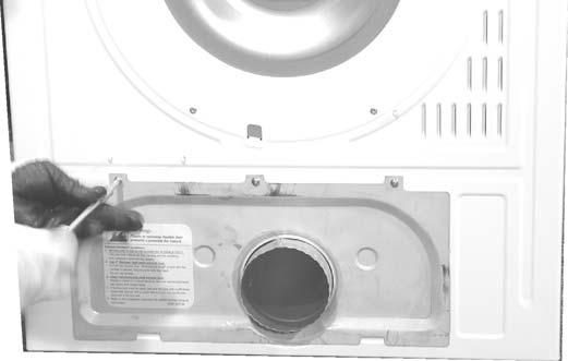
14 Disassembly Procedures! WARNING To avoid risk of electrical shock, personal injury or death; disconnect power to unit before servicing. Top Removal 1. Disconnect power supply to unit. 2. Remove 2 screws from dryer back. 4. Remove screws and Thermostats. 3. Slide Top Cover to the rear of the dryer and separate from cabinet. Resetable Thermal Fuse Hi-Limit Back Cover and Vent Tube Removal 1. Disconnect power supply to unit. 2. Remove 3 screws and Back Cover. FRONT OF DRYER SLIDE Thermostat Removal 1. Disconnect power supply to unit. 2. Remove Top Cover. 3. Remove screws and Heater Shield Rev Maytag Services


15 Disassembly Procedures! WARNING To avoid risk of electrical shock, personal injury or death; disconnect power to unit before servicing. 4. Disconnect Heater Harness plug. 5. Remove 4 screws and Heater Assembly from dryer back. 3. Pull Vent Tube from the exhaust port on the blower outlet duct. Heater Removal 1. Disconnect power supply to unit. 2. Remove Back Cover. 3. Slip Heater Harness from wire tie on the dryer back. Wiring Configuration Heater Harness Main Harness Retaining Clips View of the rear of the dryer cabinet with drum removed showing proper wire harness routing and location of Motor Harness retaining clips Maytag Services Rev. 0 15

16 Disassembly Procedures! WARNING To avoid risk of electrical shock, personal injury or death; disconnect power to unit before servicing. 6. Remove 2 nuts attaching heater element to cover. Console Removal 1. Disconnect power supply to unit. 2. Remove Top Cover. 3. Snip wire ties on the Console wire harness. CAUTION: Do not cut wire tie without having a replacement on hand. Never reassemble dryer without wire ties in place. Note: There are 2 washers between the heater element housing and the heater cover Rev Maytag Services


17 Disassembly Procedures! WARNING To avoid risk of electrical shock, personal injury or death; disconnect power to unit before servicing. 4. Remove screw inside the dryer attaching the Console to the cabinet. 7. Roll Console forward to access wiring on circuit board. 5. Unlatch the Console Blank. Circuit Board Removal 1. Disconnect power supply to unit. 2. Remove the dryer top. 3. Remove Console. 4. Remove 5 screws retaining the Circuit Board. 6. Remove screw on front face and right side of Console Maytag Services Rev. 0 17


18 Disassembly Procedures! WARNING 5. Lift Circuit Board from Console housing. To avoid risk of electrical shock, personal injury or death; disconnect power to unit before servicing. Remove Loosen Front Panel/Door/Door Switch/Drum Glide Removal 1. Disconnect power supply to unit. 2. Remove the dryer Top Cover. 3. Remove Console. 4. Remove the Toe Panel. Using a plastic Putty Knife or large coin, disengage the latches located approximately 2 in on both sides and in the center. 6. Lift and remove door. Remove remaining hinge screws. 7. Do not remove the 2 upper screws, opposite the hinge side 5. Remove 1 upper screw attaching the Door Hinge to the Front Panel. Loosen but do not remove the 1 lower screw attaching the Door Hinge to the Front Panel. Repeat this step for the lower hinge Rev Maytag Services


19 Disassembly Procedures! WARNING To avoid risk of electrical shock, personal injury or death; disconnect power to unit before servicing. 8. Remove the 2 lower screws opposite hinge side. 12.Lift Front Panel from hanger tab on cabinet. 13.Disconnect the Door Switch wire harness. 9. Do not remove the center screw. 10.Remove 4 Front Panel retaining screws under Toe Panel. 11. Remove 3 Front panel retaining screws located on the top of the Front Panel Maytag Services Rev. 0 19


20 Disassembly Procedures! WARNING CAUTION: When reassembling Front Panel route the Light Socket wire harness behind the Door Switch. This prevents the harness from contacting the rotating drum during dryer operation. To avoid risk of electrical shock, personal injury or death; disconnect power to unit before servicing. Drive Belt Removal 1. Disconnect power supply to unit. 2. Remove dryer Top Cover. 3. Remove Console. 4. Remove Front Panel. 5. Remove 3 screws attaching Blower Inlet Panel to cabinet. 14.Service Front Drum Seal and Glides as needed. 6. Lift Inlet Panel from dryer. SEAL 7. Remove 3 screws retaining Back Cover to cabinet. 8. Release tension on belt by moving Tension Pulley toward the Drive Motor. GLIDE Rev Maytag Services


21 Disassembly Procedures! WARNING 9. Slide belt forward along drum to the front of the dryer and remove. Drum Removal 1. Disconnect power supply to unit. 2. Remove dryer Top Cover. 3. Remove Console. 4. Remove Front Panel. 5. Remove Rear Panel. 6. Remove Belt. 7. Remove 4 screws retaining Front Cross Brace. To avoid risk of electrical shock, personal injury or death; disconnect power to unit before servicing. 9. Remove 1 screw retaining the Bearing Dust Cap to the cabinet back. 10.Remove Retainer Ring on drum shaft. 8. Lift Front Cross Brace from dyer Maytag Services Rev. 0 21


22 Disassembly Procedures! WARNING 11. Slide Retainer Ring and washers from drum shaft. To avoid risk of electrical shock, personal injury or death; disconnect power to unit before servicing. Rear Seal Removal 1. Disconnect power supply to unit. 2. Remove dryer Top Cover. 3. Remove Console. 4. Remove Front Panel. 5. Remove Rear Panel. 6. Remove Belt. 7. Remove Drum. 8. Pull Rear Seal away from dryer back. 12.Lift drum from dryer cabinet. Motor/Blower Removal 1. Disconnect power supply to unit. 2. Remove dryer Top Cover. 3. Remove Console. 4. Remove Front Panel. 5. Remove Rear Panel. 6. Remove Belt. 7. Remove Drum. 8. Release Tension spring from Motor Assembly Rev Maytag Services


23 Disassembly Procedures! WARNING 9. Remove 2 of the 4 screws retaining the motor bracket to the dryer base. Loosen but do not remove the remaining 2 screws and slide Motor/Blower Assembly till the screw heads align with the clearance hole in the dryer base. To avoid risk of electrical shock, personal injury or death; disconnect power to unit before servicing. 12.Remove Blower Wheel Nut. Remove Loosen Size 1/2 Size 7/8 10.Remove Thermistor or Capacitor for servicing. 13.Remove 3 screws retaining Blower Housing to Motor face. 11. Remove 7 screws to Disassemble Motor/Blower Assembly Front Cover Maytag Services Rev. 0 23


24 Disassembly Procedures! WARNING 14.Remove screws retaining Motor to Motor Bracket. To avoid risk of electrical shock, personal injury or death; disconnect power to unit before servicing. Door Reversal 1. Disconnect power supply to unit. 2. Remove top hinge screw. Loosen but do not remove lower hinge screw on the top hinge. Repeat procedure for the lower hinge. 3. Lift the door and remove from dryer. 5. Remove door skin to expose inner door panel. 4. Remove 4 screws around perimeter of door Rev Maytag Services


25 Disassembly Procedures! WARNING 6. Remove the internal door and hinge components and reassemble them to the opposite side of the Inner Door Panel. To avoid risk of electrical shock, personal injury or death; disconnect power to unit before servicing. 7. Reassemble the outer door skin to the Inner Door Panel. 8. Reassemble door to Dryer Maytag Services Rev. 0 25
26 Appendix A Rev Maytag Services
27 2004 Maytag Services Rev. 0 27

28 Rev Maytag Services

29 2004 Maytag Services Rev. 0 29

30 Rev Maytag Services

31 2004 Maytag Services Rev. 0 31

32 Rev Maytag Services

33 2004 Maytag Services Rev. 0 33
34 Rev Maytag Services

35 2004 Maytag Services Rev. 0 35
36 3-WIRE SYSTEM CONNECTIONS 1. Loosen or remove center terminal block screw. 2. Connect neutral wire (white or center wire) of power supply cord to the center, silver colored terminal screw of the terminal block. Tighten screw. 3. Connect the other wires to outer terminal block screws. Tighten screws. 4. Tighten strain relief screws. 5. Insert tab of terminal block cover into slot of dryer rear panel. Secure cover with holddown screw External ground connector 2. Neutral grounding wire (green/yellow) 3. Center silver-colored terminal block screw 4. Neutral wire (white or center wire) 5. 3/4 in. (1.9 cm) UL-listed strain relief WARNING: If converting from a 4-wire electrical system to a 3-wire, the ground strap must be reconnected to the terminal block support to ground the dryer frame to the neutral conductor. 4-WIRE SYSTEM CONNECTIONS 1. Remove center terminal block screw. 2. Remove appliance ground wire (green with yellow stripes) from external ground connector screw. Fasten it under center, silver colored terminal block screw. 3. Connect ground wire (green or bare) of power supply cord to external ground conductor screw. Tighten screw. 4. Connect neutral wire (white or center wire) of power supply cord under central screw of the terminal block. 5. Connect the other wires to outer terminal block screws. Tighten screws. 6. Tighten strain relief screws. 7. Insert tab of terminal block cover into slot of dryer rear panel. Secure cover with hold-down screw External ground connector 2. Green or bare copper wire of power supply cord 3. 3/4 in. (1.9 cm) UL-listed strain relief 4. Center silver-colored terminal block screw 5. Neutral grounding wire (green/yellow) 6. Neutral wire (white or center wire) Rev Maytag Services
37 2004 Maytag Services Rev. 0 37
38 ADDITIONAL INSTRUCTIONS FOR EXPORT MODELS (Not U.S. or Canada) Contact the distributor that sold the appliance or: Maytag International, 1475 East Woodfield Road Schaumburg, Illinois Phone: , for information on product, shipping damage, replacement parts and accessories. Maytag dryer models manufactured for operation on 60 Hz AC are not designed for use on 50 Hz AC electrical service and conversion of the product from 60 to 50 Hz operation is not recommended. For additional information on 50 Hz products, contact Maytag International. The electric service requirements can be found on the data label located on the front of the dryer behind the door EXPORT ELECTRIC MODELS Export electric models are manufactured for operation on either 230/240 volt, 50 Hz or 220 volt, 60 Hz approved electric service. A two-wire approved electrical service with a 30- ampere fuse or circuit breaker is required. The dryer must be properly grounded with a ground wire. IMPORTANT: When permitted by local codes, the dryer electrical supply may be connected by means of a new power supply cord kit, marked for use with clothes dryers, that is agency listed, rated at 240 volts minimum, 30 amperes with two No. 10 copper wire conductors terminated with closed loop terminals, open-end spade lugs with turned up ends or with tinned leads. Do not reuse a power supply cord from an old dryer. The power cord or electric supply wiring must be retained at the dryer cabinet with a suitable agency listed strain relief. 2-WIRE SYSTEM CONNECTIONS 1. Loosen or remove center terminal block screw. 2. Connect neutral wire (white or center wire) of power supply cord to the center, silver colored terminal screw of the terminal block. Tighten screw. 3. Connect the other wires to outer terminal block screws. Tighten screws. 4. Tighten strain relief screws. 5. Insert tab of terminal block cover into slot of dryer rear panel. Secure cover with hold-down screw External ground connector 2. Neutral grounding wire (green/yellow) 3. Center silver-colored terminal block screw 4. Neutral wire (white or center wire) 5. 3/4 in. (1.9 cm) UL-listed strain relief BEFORE OPERATING OR TESTING, be sure the machine is properly grounded Rev Maytag Services
39 Appendix B 2004 Maytag Services Rev. 0 39


40 Rev Maytag Services
41 2004 Maytag Services Rev. 0 41
42 Rev Maytag Services
43 2004 Maytag Services Rev. 0 43
44 Rev Maytag Services
45 2004 Maytag Services Rev. 0 45
46 Rev Maytag Services
47 2004 Maytag Services Rev. 0 47
48 Rev Maytag Services
49 2004 Maytag Services Rev. 0 49
50 Rev Maytag Services
51 2004 Maytag Services Rev. 0 51
! WARNING To avoid risk of electrical shock, personal injury or death; disconnect power to dryer before servicing, unless testing requires power.
 Electric Dryer Technical Information CDE4205A* Due to possibility of personal injury or property damage, always contact an authorized technician for servicing or repair of this unit. Refer to Service Manual
! WARNING To avoid risk of electrical shock, personal injury or death; disconnect power before servicing, unless testing requires power.
 27 Electric Dryer Technical Information MDE9700A * Due to possibility of personal injury or property damage, always contact an authorized technician for servicing or repair of this unit. Refer to Service
Service. 27 Dryer MDE9700A* MDG9700A*
 Service This manual is to be used by qualified appliance technicians only. Maytag does not assume any responsibility for property damage or personal injury for improper service procedures done by an unqualified
! WARNING To avoid risk of electrical shock, personal injury or death; disconnect power to dryer before servicing, unless testing requires power.
 27 Domestic Dryer Technical Information MDE6700A*, MDG6700A* Due to possibility of personal injury or property damage, always contact an authorized technician for servicing or repair of this unit. Refer
! WARNING To avoid risk of electrical shock, personal injury or death; disconnect power to dryer before servicing, unless testing requires power.
 Electric Dryer Technical Information CDG4205A* Due to possibility of personal injury or property damage, always contact an authorized technician for servicing or repair of this unit. Refer to Service Manual
! WARNING To avoid risk of electrical shock, personal injury or death; disconnect power before servicing, unless testing requires power.
 27 Gas Dryer Technical Information MDG9700A * Due to possibility of personal injury or property damage, always contact an authorized technician for servicing or repair of this unit. Refer to Service Manual
CLOTHES DRYER Technical Information
 CLOTHES DRYER Technical Information Due to possibility of personal injury or property damage, always contact an authorized technician for servicing or repair of this unit. Refer to Service Manual (DV456*,DV422*,DV400*)
CLOTHES DRYER Technical Information
 CLOTHES DRYER Technical Information IMPORTANT SAFETY NOTICE For Technicians only This service data sheet is intended for use by persons having electrical, electronic, and mechanical experience and knowledge
An occurrence of an Error will make a sound of error melody for 5sec and continuously show one of the Error Displays from the following errors.
 4. Troubleshooting 4-1. Error items and diagnostic codes An occurrence of an Error will make a sound of error melody for 5sec and continuously show one of the Error Displays from the following errors.
Test/Function Wrinkle release. Display list of diagnostic codes. Then press Temperature (^) - 13 Key. To sequence thru the diagnostic and help codes.
 - 13 Key. To sequence thru the diagnostic and help codes.") Trouble Shooting! WARNING To avoid risk of electrical shock, personal injury, death, disconnect power to washer befe servicing, unless testing requires it. Troubleshooting Guide Maytag Neptune LED Gas
Trouble Shooting! WARNING To avoid risk of electrical shock, personal injury, death, disconnect power to washer befe servicing, unless testing requires it. Troubleshooting Guide Maytag Neptune LED Gas
Dryer. User manual DV22K6800** DV22K A-00_EN (US)_ indd :15:41
_ indd :15:41") Dryer User manual DV22K6800** DV22K6800-03650A-00_EN (US)_151211.indd 1 2015-12-11 7:15:41 Before installation Read through the following instructions before installing the dryer, and keep this manual
Dryer User manual DV22K6800** DV22K6800-03650A-00_EN (US)_151211.indd 1 2015-12-11 7:15:41 Before installation Read through the following instructions before installing the dryer, and keep this manual
Installation Instructions
 Installation Instructions Before you begin... 2 Location... 2 Recommended grounding instructions... 2 Electrical requirements... 2 Exhaust requirements... 3 Water supply and drain requirements... 3 Please
Installation Electric Dryers Instructions 01
 Installation Electric Dryers Instructions 01 Questions? Call 800.GE.CARES (800.432.2737) or visit our Web site at: GEAppliances.com This is the safety alert symbol. This symbol alerts you to potential
AUTOMATIC DRYER INSTALLATION INSTRUCTIONS MISE EN SERVICE SÉCHEUSE AUTOMATIQUE INSTRUCCIONES DE INSTALACIÓN DE LA SECADORA AUTOMÁTICA
 AUTOMATIC DRYER INSTALLATION INSTRUCTIONS MISE EN SERVICE SÉCHEUSE AUTOMATIQUE INSTRUCCIONES DE INSTALACIÓN DE LA SECADORA AUTOMÁTICA The installation, including a proper exhaust system, is the responsibility
COMMERCIAL ELECTRIC DRYER
 COMMERCIAL ELECTRIC DRYER MODEL MDE22PNAGW0 1 10 Litho In U.S.A. (BT)(bay) c 2010 WHIRLPOOL CORPORATION Part No. Rev. B TOP AND CONSOLE PARTS WIRING HARNESS PARTS 2 TOP AND CONSOLE PARTS 1 Literature Parts
Questions on Installation? Call: GECARES (US) or Visit our Web site at: (US) 4" DUCT CLAMPS (2) OR 4" SPRING CLAMPS (2)
 or Visit our Web site at: (US) 4 DUCT CLAMPS (2) OR 4 SPRING CLAMPS (2)") Installation Instructions Questions on Installation? Call: 1-800-GECARES (US) or Visit our Web site at: www.geappliances.com (US) Electric Dryer 49 37 BEFORE YOU BEGIN Read these instructions completely
Installation Instructions Questions on Installation? Call: 1-800-GECARES (US) or Visit our Web site at: www.geappliances.com (US) Electric Dryer 49 37 BEFORE YOU BEGIN Read these instructions completely
COMMERCIAL ELECTRIC DRYER MODELS: MLE27PDBYW1 (White) 01/19/ Maytag Part No. W Rev. A
 01/19/ Maytag Part No. W Rev. A") COMMERCIAL ELECTRIC DRYER MODELS: MLE27PDBYW1 (White) 01/19/2016 2016 Maytag Part W10856883 Rev. A CONTROL PANEL AND SEPARATOR PARTS 01/19/2016 2 Part W10856883 Rev. A CONTROL PANEL AND SEPARATOR PARTS
COMMERCIAL ELECTRIC DRYER MODELS: MLE27PDBYW1 (White) 01/19/2016 2016 Maytag Part W10856883 Rev. A CONTROL PANEL AND SEPARATOR PARTS 01/19/2016 2 Part W10856883 Rev. A CONTROL PANEL AND SEPARATOR PARTS
27 ELECTRIC & GAS DRYERS
 CONSUMER SERVICES TECHNICAL EDUCATION GROUP PRESENTS L-63 27 ELECTRIC & GAS DRYERS JOB AID Part No. 4322260 I INTRODUCTION This Job Aid, 27 ELECTRIC & GAS DRYERS, (Part No. 4322260), provides specific
29 IN. (73.7 CM) ELECTRIC DRYER INSTALLATION INSTRUCTIONS DRYER SAFETY
 ELECTRIC DRYER INSTALLATION INSTRUCTIONS DRYER SAFETY") 9 IN. (7.7 CM) ELECTRIC DRYER INSTALLATION INSTRUCTIONS DRYER SAFETY... INSTALLATION INSTRUCTIONS... Tools and Parts... Location Requirements... Electrical Requirements... Electrical Connection...4 Venting
9 IN. (7.7 CM) ELECTRIC DRYER INSTALLATION INSTRUCTIONS DRYER SAFETY... INSTALLATION INSTRUCTIONS... Tools and Parts... Location Requirements... Electrical Requirements... Electrical Connection...4 Venting
Questions? Call 800.GE.CARES ( ) or visit our Web site at: GEAppliances.com In Canada, call or visit
 or visit our Web site at: GEAppliances.com In Canada, call or visit") Installation Instructions Electric Dryer 01 Questions? Call 800.GE.CARES (800.432.2737) or visit our Web site at: GEAppliances.com In Canada, call 1.800.561.3344 or visit www.geappliances.ca BEFORE YOU
Installation Instructions Electric Dryer 01 Questions? Call 800.GE.CARES (800.432.2737) or visit our Web site at: GEAppliances.com In Canada, call 1.800.561.3344 or visit www.geappliances.ca BEFORE YOU
Home Stack Washer/Dryers
 Home Stack Washer/Dryers Refer to Page 3 for Model Numbers Parts SWD456C_806093 www.alliancelaundry.com Part No. 806093R1 December 2016 Table of Contents Title Page Parts Ordering Information... 2 Serial
AUTOMATIC DRYER INSTALLATION INSTRUCTIONS
 AUTOMATIC DRYER INSTALLATION INSTRUCTIONS The installation, including a proper exhaust system, is the responsibility of the owner. LEAVE THESE INSTRUCTIONS WITH THE OWNER Printed in U.S.A. 6 37699 Read
THE READY RACK 2 GEAR PPE DRYING CABINET. Operator s Manual & Installation Guide. Installation/Operation/Maintenance/Part Number I
 THE READY RACK 2 GEAR PPE DRYING CABINET Operator s Manual & Installation Guide Installation/Operation/Maintenance/Part Number 820220I Copy right 2016 Forward We are pleased that you have selected a Ready
Gas and Electric Dryer user manual
 DV48H7400E(G)* DV45H7400E(G)* DV45H7200E(G)* DV45H7000E(G)* Gas and Electric Dryer user manual This manual is made with 100% recycled paper. imagine the possibilities Thank you for purchasing this Samsung
Installation Instructions Remote Blowers
 Installation Instructions Remote Blowers Models: REMP3, REMP16 Suitable for use in a household cooking area. Suitable for use with solid state controls. To complete this blower, a Dacor hood assembly or
User's Manual. Exhaust Type Tumble Dryer HLP140E. Please read this manual carefully before using. Retain it for future reference.
 Exhaust Type Tumble Dryer User's Manual HLP140E Please read this manual carefully before using. Retain it for future reference. Names Of The Parts Transparent Windows Door Drum Exhaust Shroud Air Intake
COMMERCIAL ELECTRIC DRYER
 COMMERCIAL ELECTRIC DRYER MODEL MLE24PNAGW0 7 09 Litho in U.S.A. (BT)(bay) c 2009 WHIRLPOOL CORPORATION Part No. Rev. A LOWER CABINET AND FRONT PANEL PARTS 2 LOWER CABINET AND FRONT PANEL PARTS 1 Literature
Home Stack Washer/Dryers
 Home Stack Washer/Dryers Refer to Page 3 for Model Numbers Parts SWD456C_806093 www.alliancelaundry.com Part No. 806093R4 September 2018 Table of Contents Title Page Parts Ordering Information... 2 Serial
29" GAS DRYER MODELS: MGD7000AW1 (White) MGD7000AG1 (Cosmetallic) 07/02/ Maytag Part No. W Rev. A
 MGD7000AG1 (Cosmetallic) 07/02/ Maytag Part No. W Rev. A") 29" GAS DRYER MODELS: MGD7000AW1 (White) MGD7000AG1 (Cosmetallic) 07/02/2013 2013 Maytag Part W10624907 Rev. A TOP AND CONSOLE PARTS 07/02/2013 2 Part W10624907 Rev. A TOP AND CONSOLE PARTS Part Description
29" GAS DRYER MODELS: MGD7000AW1 (White) MGD7000AG1 (Cosmetallic) 07/02/2013 2013 Maytag Part W10624907 Rev. A TOP AND CONSOLE PARTS 07/02/2013 2 Part W10624907 Rev. A TOP AND CONSOLE PARTS Part Description
Questions? Call 800.GE.CARES ( ) or visit our Web site at: GEAppliances.com In Canada, call or visit
 or visit our Web site at: GEAppliances.com In Canada, call or visit") Installation Instructions Electric Dryer 01 Questions? Call 800.GE.CARES (800.432.2737) or visit our Web site at: GEAppliances.com In Canada, call 1.800.561.3344 or visit www.geappliances.ca BEFORE YOU
Installation Instructions Electric Dryer 01 Questions? Call 800.GE.CARES (800.432.2737) or visit our Web site at: GEAppliances.com In Canada, call 1.800.561.3344 or visit www.geappliances.ca BEFORE YOU
Commercial Single and Stack Dryers
 This manual is to be used by qualified appliance technicians only. Maytag does not assume any responsibility for property damage or personal injury for improper service procedures done by an unqualified
Homestyle Stack Washer/Dryers
 Homestyle Stack Washer/Dryers Refer to Page 3 for Model Numbers Parts SWD456C_806105 www.alliancelaundry.com Part No. 806105R1 November 2015 Table of Contents Title Page Parts Ordering Information...
TOP AND CONSOLE PARTS
 TOP AND CONSOLE PARTS 27" ELECTRIC DRYER 6 12 Printed in U.S.A. (GG)(bay) 1 Part No. Rev. A TOP AND CONSOLE PARTS 1 Literature Parts W10392124 Installation, Diagnostic Guide W10388780 Guide, Use & Care
27" GAS DRYER MODELS: MGD7100DW0 (White) MGD7100DC0 (Chrome Shadow) 05/08/ Maytag Part No. W Rev. A
 MGD7100DC0 (Chrome Shadow) 05/08/ Maytag Part No. W Rev. A") 27" GAS DRYER MODELS: MGD7100DW0 (White) MGD7100DC0 (Chrome Shadow) 05/08/2014 2014 Maytag Part W10712329 Rev. A TOP AND CONSOLE PARTS 05/08/2014 2 Part W10712329 Rev. A TOP AND CONSOLE PARTS Part Description
27" GAS DRYER MODELS: MGD7100DW0 (White) MGD7100DC0 (Chrome Shadow) 05/08/2014 2014 Maytag Part W10712329 Rev. A TOP AND CONSOLE PARTS 05/08/2014 2 Part W10712329 Rev. A TOP AND CONSOLE PARTS Part Description
COMMERCIAL ELECTRIC DRYER
 COMMERCIAL ELECTRIC DRYER MODEL CEW9100VQ0 c 2012 WHIRLPOOL CORPORATION 4 12 Litho In U.S.A. (CMS) (psw) Part No. Rev. B TOP AND CONSOLE PARTS 2 TOP AND CONSOLE PARTS 1 Literature Parts W10184516 Installation
Service. Vent Hoods November Maytag Services
 Service This manual is to be used by qualified appliance technicians only. Maytag does not assume any responsibility for property damage or personal injury for improper service procedures done by an unqualified
COMMERCIAL ELECTRIC DRYER MODELS: MLE26PDBZW1 (White) 01/14/ Maytag Part No. W Rev. A
 01/14/ Maytag Part No. W Rev. A") COMMERCIAL ELECTRIC DRYER MODELS: MLE26PDBZW1 (White) 01/14/2016 2016 Maytag Part W10856858 Rev. A CONTROL PANEL AND SEPARATOR PARTS 01/14/2016 2 Part W10856858 Rev. A CONTROL PANEL AND SEPARATOR PARTS
COMMERCIAL ELECTRIC DRYER MODELS: MLE26PDBZW1 (White) 01/14/2016 2016 Maytag Part W10856858 Rev. A CONTROL PANEL AND SEPARATOR PARTS 01/14/2016 2 Part W10856858 Rev. A CONTROL PANEL AND SEPARATOR PARTS
COMMERCIAL STACKED GAS DRYER/WASHER
 COMMERCIAL STACKED GAS DRYER/WASHER MODEL NO. CGT8000XQ0 c 2012 WHIRLPOOL CORPORATION 5 12 Litho In U.S.A. (CMS) (bay) Part No. Rev. H CONTROL PANEL PARTS 2 CONTROL PANEL PARTS 1 Literature Parts W10335467
COMMERCIAL STACKED. Supersedes repair parts list located behind lower panel on washer. Models: CGT8000AQ1 (White)
") PARTS LIST for COMMERCIAL STACKED Supersedes repair parts list located behind lower panel on washer Models: CGT8000AQ1 (White) FOR CUSTOMER SATISFACTION ALWAYS USE FACTORY SPECIFICATION PARTS 201210001
PARTS LIST for COMMERCIAL STACKED Supersedes repair parts list located behind lower panel on washer Models: CGT8000AQ1 (White) FOR CUSTOMER SATISFACTION ALWAYS USE FACTORY SPECIFICATION PARTS 201210001
Drying Tumblers. Troubleshooting. 120 Pound Capacity 170 Pound Capacity. Refer to Page 5 for Model Numbers. Part No August 2007
 HIGH LOAD READY MEDIUM TEMPERATURE LOW LOW AIR FLOW NON REV REV PUSH TO START 10 5 15 0 50 40 60 0 30 10 20 Drying Tumblers 120 Pound Capacity 170 Pound Capacity Page 5 for Model Numbers Troubleshooting
GAS DRYER MODELS: MGD8200FW0 (White) MGD8200FC0 (Chrome Shadow) 05/24/ Maytag Part No. W Rev. A
 MGD8200FC0 (Chrome Shadow) 05/24/ Maytag Part No. W Rev. A") GAS DRYER MODELS: MGD8200FW0 (White) MGD8200FC0 (Chrome Shadow) 05/24/2016 2016 Maytag Part W10884161 Rev. A TOP AND CONSOLE PARTS 05/24/2016 2 Part W10884161 Rev. A TOP AND CONSOLE PARTS Part Description
GAS DRYER MODELS: MGD8200FW0 (White) MGD8200FC0 (Chrome Shadow) 05/24/2016 2016 Maytag Part W10884161 Rev. A TOP AND CONSOLE PARTS 05/24/2016 2 Part W10884161 Rev. A TOP AND CONSOLE PARTS Part Description
GAS DRYER MODELS: WGD8000DW0 (White) 03/30/ Whirlpool Corporation Part No. W Rev. C
 03/30/ Whirlpool Corporation Part No. W Rev. C") GAS DRYER MODELS: WGD8000DW0 (White) 03/30/2015 2015 Whirlpool Corporation Part W10743192 Rev. C TOP AND CONSOLE PARTS 03/30/2015 2 Part W10743192 Rev. C TOP AND CONSOLE PARTS Part Description 1 Literature
GAS DRYER MODELS: WGD8000DW0 (White) 03/30/2015 2015 Whirlpool Corporation Part W10743192 Rev. C TOP AND CONSOLE PARTS 03/30/2015 2 Part W10743192 Rev. C TOP AND CONSOLE PARTS Part Description 1 Literature
Washer-Extractor. Troubleshooting. Cabinet Hardmount Mechanical Timer Refer to Page 8 for Model Numbers.
 Washer-Extractor Cabinet Hardmount Mechanical Timer Refer to Page 8 for Model Numbers Troubleshooting CHM1624C www.comlaundry.com Part No. F232202R3 November 2011 Table of Contents Safety Information...3
Home Stacked Washer/Dryer
 Home Stacked Washer/Dryer Refer to Page 3 for Model Numbers Parts SWD443C_802107 www.comlaundry.com Part No. 802107R6 August 2014 Table of Contents Title Page Parts Ordering Information... 2 Serial Plate
PUREPOWER SERIES CENTRAL VACUUM POWER UNITS PP500, PP600 & PP650
 USER GUIDE PUREPOWER SERIES CENTRAL VACUUM POWER UNITS PP500, PP600 & PP650 AB0039 FOR RESIDENTIAL USE ONLY!! MODELS SFDB-DQ, SFDB-DR AND SFDB-DS 30042509E IMPORTANT SAFETY INSTRUCTIONS SAVE THESE INSTRUCTIONS
Summer Breeze Heater Service Manual
 Summer Breeze Heater Service Manual RSBH RSBH-SB RSBHP Revision: 1.0 Issued: 12-18-2012 Table of Contents I. Basic Assembly and Operation A. Safety Instructions... 2 B. Grounding Instructions... 3 C.
GAS DRYER MODELS: (White) (Chrome Shadow) 01/28/ Sears Brands, LLC Part No. W Rev. A
 (Chrome Shadow) 01/28/ Sears Brands, LLC Part No. W Rev. A") GAS DRYER MODELS: 110.78132413 (White) 110.78133413 (Chrome Shadow) 01/28/2016 2016 Sears Brands, LLC Part W10865713 Rev. A TOP AND CONSOLE PARTS 01/28/2016 2 Part W10865713 Rev. A TOP AND CONSOLE PARTS
GAS DRYER MODELS: 110.78132413 (White) 110.78133413 (Chrome Shadow) 01/28/2016 2016 Sears Brands, LLC Part W10865713 Rev. A TOP AND CONSOLE PARTS 01/28/2016 2 Part W10865713 Rev. A TOP AND CONSOLE PARTS
Installation Instructions Dual Fuel Ranges
 Installation Instructions Dual Fuel Ranges E30DF74EPS E36DF76EPS E48DF76EPS 5995447082 2 Safety IMPORTANT SAFETY INSTRUCTIONS Safety Precautions Do not attempt to install or operate your unit until you
27" GAS DRYER MODELS: WGD95HEDW0 (White) WGD95HEDC0 (Chrome Shadow) 05/13/ Whirlpool Corporation Part No. W Rev.
 WGD95HEDC0 (Chrome Shadow) 05/13/ Whirlpool Corporation Part No. W Rev.") 27" GAS DRYER MODELS: WGD95HEDW0 (White) WGD95HEDC0 (Chrome Shadow) 05/13/2014 2014 Whirlpool Corporation Part W10710285 Rev. A TOP AND CONSOLE PARTS 05/13/2014 2 Part W10710285 Rev. A TOP AND CONSOLE
27" GAS DRYER MODELS: WGD95HEDW0 (White) WGD95HEDC0 (Chrome Shadow) 05/13/2014 2014 Whirlpool Corporation Part W10710285 Rev. A TOP AND CONSOLE PARTS 05/13/2014 2 Part W10710285 Rev. A TOP AND CONSOLE
Installation Instructions
 Installation Instructions for Dryers Inside... Dimensions... Before You Start... 4 Installing the Dryer... 5 Installer Checklist... Back Cover Date Purchased Model Number Serial Number Keep these instructions
27" Gas Dryer MODELS: MGDB950YW3 (White) MGDB950YG3 (Cosmetallic) 05/31/ Maytag Part No. W Rev. A
 MGDB950YG3 (Cosmetallic) 05/31/ Maytag Part No. W Rev. A") 27" Gas Dryer MODELS: MGDB950YW3 (White) MGDB950YG3 (Cosmetallic) 05/31/2013 2013 Maytag Part W10617393 Rev. A TOP AND CONSOLE PARTS 05/31/2013 2 Part W10617393 Rev. A TOP AND CONSOLE PARTS Part Description
27" Gas Dryer MODELS: MGDB950YW3 (White) MGDB950YG3 (Cosmetallic) 05/31/2013 2013 Maytag Part W10617393 Rev. A TOP AND CONSOLE PARTS 05/31/2013 2 Part W10617393 Rev. A TOP AND CONSOLE PARTS Part Description
Homestyle Stacked Washer/ Dryer
 Homestyle Stacked Washer/ Dryer Parts Refer to Page 3 for Model Numbers SWD441C_801998 www.alliancelaundry.com Part No. 801998R6 January 2018 Table of Contents Title Page Parts Ordering Information...
Homestyle Stacked Washer/Dryer
 Homestyle Stacked Washer/Dryer Parts Refer to Page 3 for Model Numbers SWD443C_801802 www.alliancelaundry.com Part No. 801802R8 January 2018 Table of Contents Title Page Parts Ordering Information...
ELECTRIC COOKTOP INSTALLATION INSTRUCTIONS
 INSTALLATION AND SERVICE MUST BE PERFORMED BY A QUALIFIED INSTALLER. IMPORTANT: SAVE FOR LOCAL ELECTRICAL INSPECTOR'S USE. READ AND SAVE THESE INSTRUCTIONS FOR FUTURE REFERENCE. U.S.A. WARNING FOR YOUR
INSTALLATION INSTRUCTIONS TD75. Vented tumble dryer DOMESTIC. Carefully read the instructions for use before using the dryer.
 INSTALLATION INSTRUCTIONS TD75 Vented tumble dryer DOMESTIC Carefully read the instructions for use before using the dryer. Dear Customer, Read these instructions carefully and completely before you install
WASHER/DRYER CONTROL PANEL PARTS
 WASHER/DRYER CONTROL PANEL PARTS WASHER/DRYER LAUNDRY SYSTEM 1 Literature Parts W10356098 Installation Instructions W10343071 Guide, Use & Care W10364010 Wiring Diagram W10343084 Energy Guide 2 3390688
INSTALLATION INSTRUCTIONS INSTRUCTIONS D INSTALLATION INSTRUCCIONES DE INSTALACIÓN
 EN FRONT LOAD DRYER FR SÉCHEUSE Á CHARGEMENT FRONTAL ES SECADORA DE CARGA FRONTAL INSTALLATION INSTRUCTIONS INSTRUCTIONS D INSTALLATION INSTRUCCIONES DE INSTALACIÓN 2 IMPORTANT SAFETY INSTRUCTIONS For
Installation Instructions
 Installation Instructions Gas & Electric Dryer Before beginning installation, carefully read these instructions. This will simplify the installation and ensure the dryer is installed correctly and safely.
owner s manual & parts list
 AVIATOR owner s manual & parts list This equipment is intended for commercial use only. 3009AF 3009AF-W 1753 Blake Avenue Los Angeles, CA 90031 (800) 338-EDIC Or (323) 660-1635 Fax (323) 667-0144 BEFORE
Neptune DC MCE8000AY MCG8000AW
 This manual is to be used by qualified appliance technicians only. Maytag does not assume any responsibility for property damage or personal injury for improper service procedures done by an unqualified
DRYER INSTALLATION INSTRUCTIONS
 DRYER INSTALLATION INSTRUCTIONS Table of Contents DRYER SAFETY... 1 INSTALLATION REQUIREMENTS... 2 Tools and Parts... 2 Location Requirements... 3 Electrical Requirements... 5 INSTALLATION INSTRUCTIONS...
Please read the following installation instructions first after purchasing this product or transporting it to another location.
 0 INSTALLATION INSTALLATION Installation Overview Please read the following installation instructions first after purchasing this product or transporting it to another location. Check and choose the proper
Homestyle Stacked Washer/Dryer
 Homestyle Stacked Washer/Dryer Parts Refer to Page 3 for Model Numbers SWD452C_802847 www.comlaundry.com Part No. 802847R8 August 2012 Table of Contents Title Page Parts Ordering Information... 2 Nameplate
27" GAS DRYER MODELS: 7MWGD87HEDC0 (Chrome Shadow) 08/19/ Whirlpool Corporation Part No. W Rev. A
 08/19/ Whirlpool Corporation Part No. W Rev. A") 27" GAS DRYER MODELS: 7MWGD87HEDC0 (Chrome Shadow) 08/19/2014 2014 Whirlpool Corporation Part W10738517 Rev. A TOP AND CONSOLE PARTS 08/19/2014 2 Part W10738517 Rev. A TOP AND CONSOLE PARTS 1 Literature
27" GAS DRYER MODELS: 7MWGD87HEDC0 (Chrome Shadow) 08/19/2014 2014 Whirlpool Corporation Part W10738517 Rev. A TOP AND CONSOLE PARTS 08/19/2014 2 Part W10738517 Rev. A TOP AND CONSOLE PARTS 1 Literature
W Model 1RKU2 w/optional Wall mount. Unit Model Weight (Lbs) Kilowatts Volts- Phase Amps Fan Output Heat Output
 Kilowatts Volts- Phase Amps Fan Output Heat Output") Operating Instructions & Parts Manual 1RKT2, 1RKT3, 1RKT4, 1RKT5, 1RKT9 and 1RKU2 Please read and save these instructions. Read carefully before attempting to assemble, install, operate or maintain the
Operating Instructions & Parts Manual 1RKT2, 1RKT3, 1RKT4, 1RKT5, 1RKT9 and 1RKU2 Please read and save these instructions. Read carefully before attempting to assemble, install, operate or maintain the
WET/DRY VACUUM. QUEST for Continuous Improvement Windsor s Quality Management System is Certified ISO MODEL: T1. Operating Instructions (ENG)
") WET/DRY VACUUM Operating Instructions (ENG) MODEL: T1 y QUEST for Continuous Improvement Windsor s Quality Management System is Certified ISO 9001. Read these instructions before operating the machine.
WET/DRY VACUUM Operating Instructions (ENG) MODEL: T1 y QUEST for Continuous Improvement Windsor s Quality Management System is Certified ISO 9001. Read these instructions before operating the machine.
DISHWASHER. Models DW2432 and DW2432SS. Installation Manual. Write Serial Number (on inner door of unit) here:
 here:") DISHWASHER Models DW2432 and DW2432SS Installation Manual Write Serial Number (on inner door of unit) here: Felix Storch, Inc. Summit Appliance Division 770 Garrison Avenue Bronx, New York 10474 www.summitappliance.com
DISHWASHER Models DW2432 and DW2432SS Installation Manual Write Serial Number (on inner door of unit) here: Felix Storch, Inc. Summit Appliance Division 770 Garrison Avenue Bronx, New York 10474 www.summitappliance.com
Installation Instructions Wall Ovens
 Installation Instructions Wall Ovens TESTED IN ACCORDANCE WITH THE LATEST EDITION OF UL858 STANDARD FOR HOUSEHOLD ELECTRIC COOKING APPLIANCES. IMPORTANT 1. Before beginning installation, please thoroughly
INSTALLATION INSTRUCTIONS ELECTRIC DRYER
 INSTALLATION INSTRUCTIONS ELECTRIC DRYER Table of Contents... 2 IMPORTANT: Save for local electrical inspector s use. 3397627C DRYER SAFETY... 2 INSTALLATION INSTRUCTIONS... 4 Tools and Parts... 4 Location
Installation Instructions
 Instructions for Stacked Dryers Original Instructions Keep These Instructions for Future Reference. (If this machine changes ownership, this manual must accompany machine.) www.speedqueen.com Part No.
Commercial Stacked Dryers Metered and Nonmetered Refer to Page 3 for Model Numbers
 Commercial Stacked Dryers Metered and Nonmetered Refer to Page 3 for Model Numbers Service www.comlaundry.com Part No. 53277R2 January 2002 Table of Contents Section 1 Safety Information Locating an Authorized
Service Manual Electric Cooktop
 Service Manual Electric Cooktop 318 202 105 (0311) THIS IS A BLANK PAGE Table of Contents I SAFE SERVICING PRACTICES... 1 PRODUCT FEATURES... 2 WIRING DIAGRAM... 3 SECTION A - INSTALLATION... 4 CUT-OUT
e Bath Fan with Light User s Guide
 e Bath Fan with Light User s Guide abfl100rnl, BFL125RNL Item Stock Number(s): BFL100RNL, BFL125RNL IMPORTANT INSTRUCTIONS - OPERATING MANUAL READ AND SAVE THESE INSTRUCTIONS READ CAREFULLY BEFORE ATTEMPTING
Stacked Clothes Dryer Nonmetered and Metered
 Stacked Clothes Dryer Nonmetered and Metered Electric and Gas Models Installation/Operation Para bajar una copia de estas instrucciones en español, visite www.comlaundry.com. D009C Keep These Instructions
Installation Instructions T 9822 Gas Dryer. en - US, CA. To prevent accidents
 Installation Instructions T 9822 Gas Dryer To prevent accidents en - US, CA and appliance damage read these instructions before installation or use. M.-Nr. 07 431 110 2 WARNING For your safety the information
READ AND SAVE THESE INSTRUCTIONS READ CAREFULLY BEFORE ATTEMPTING TO ASSEMBLE, INSTALL, OPERATE OR MAINTAIN THE PRODUCT DESCRIBED. PROTECT YOURSELF AN
 READ AND SAVE THESE INSTRUCTIONS READ CAREFULLY BEFORE ATTEMPTING TO ASSEMBLE, INSTALL, OPERATE OR MAINTAIN THE PRODUCT DESCRIBED. PROTECT YOURSELF AND OTHERS BY OBSERVING ALL SAFETY INFORMATION. FAILURE
Installation Instructions
 Instructions for Dryers Original Instructions Keep These Instructions for Future Reference. CAUTION: Read the instructions before using the machine. (If this machine changes ownership, this manual must
Installation. Built-In Electric Cooktop. Viking Range, LLC 111 Front Street Greenwood, Mississippi USA (662)
") Installation Viking Range, LLC 111 Front Street Greenwood, Mississippi 38930 USA (662) 455-1200 For product information, call 1-888-845-4641 or visit the Viking Website at vikingrange.com Built-In Electric
Installation Viking Range, LLC 111 Front Street Greenwood, Mississippi 38930 USA (662) 455-1200 For product information, call 1-888-845-4641 or visit the Viking Website at vikingrange.com Built-In Electric
PUREPOWER SERIES CENTRAL VACUUM POWER UNITS PP500, PP600 & PP650
 USER GUIDE PUREPOWER SERIES CENTRAL VACUUM POWER UNITS PP500, PP600 & PP650 AB0039 FOR RESIDENTIAL USE ONLY!! BROAN-NUTONE LLC; HARTFORD, WISCONSIN WWW.NUTONE.COM 1-888-336-3948 REGISTER YOUR PRODUCT ONLINE
Installation Instructions
 Instructions for Dryers Original Instructions Keep These Instructions for Future Reference. (If this machine changes ownership, this manual must accompany machine.) www.alliancelaundry.com Part No. D5486ENR
Clothes Dryer Electric and Gas Models
 Clothes Dryer Electric and Gas Models Installation/Operation DRY684C Para bajar una copia de estas instrucciones en español, visite www.comlaundry.com. Keep These Instructions for Future Reference. (If
COMMERCIAL ELECTRIC DRYER
 COMMERCIAL ELECTRIC DRYER MODEL YCEM2760TQ1 1 09 Litho in U.S.A. (LT)(bay) c 2008 WHIRLPOOL CORPORATION Part No. Rev. A TOP AND CONSOLE PARTS WIRING HARNESS PARTS 2 TOP AND CONSOLE PARTS 1 Literature Parts
Commercial Stacked Washer/ Dryers
 Commercial Stacked Washer/ Dryers Parts Refer to Page 3 for Model Numbers SWD446C_801771 www.comlaundry.com Part No. 801771R4 March 2010 Table of Contents Title Page Parts Ordering Information... 2 Nameplate
Installation GUIDE VDWU524SS VDWU524WSSS FDWU524WS FDWU524 VDWU324SS FDWU324
 Installation GUIDE VDWU524SS VDWU524WSSS FDWU524WS FDWU524 VDWU324SS FDWU324 To prevent accidents, which could cause serious injury or death, as well as machine damage read these instructions before installation
GAS AND ELECTRIC DRYERS
 CONSUMER SERVICES TECHNICAL EDUCATION GROUP PRESENTS L-69 GAS AND ELECTRIC DRYERS Model Numbers: GGW9200L & GEW9200L JOB AID Part No. 8178071 FORWARD This Whirlpool Job Aid, Duet Gas and Electric Dryers,
Automatic Dryers. Installation. Keep These Instructions for Future Reference. (If this machine changes ownership, this manual must accompany machine.
 Automatic Dryers Installation D715I Keep These Instructions for Future Reference. (If this machine changes ownership, this manual must accompany machine.) Part No. R4 June 2007 IMPORTANT: The electrical
Service Manual. Trash Compactor. Models 15SSEXF 15BLEXF A November 2010
 Service Manual Trash Compactor Models 15SSEXF 15BLEXF 99044662A November 2010 Broan-NuTone LLC 926 West State Street Hartford, WI 53027 1-800-637-1453 2 Safe Servicing Practices Safe Servicing Practices
Fast Track Troubleshooting
 Fast Track Troubleshooting Models: DV5471AE DV5471AG NOTICE: All Dryers Parts Change 6/2010: Motor Pulley, page 5; Blower Housing, page 4 IMPORTANT SAFETY NOTICE For Technicians Only This service data
WASHER/DRYER CONTROL PANEL PARTS For Model: YWET3300SQ0 (Designer White)
") WASHER/DRYER CONTROL PANEL PARTS WASHER/DRYER LAUNDRY SYSTEM 1 Literature Parts Installation Instructions W10118289 English 8578179 English W10118304 Sheet, Cycle Feature W10113806 Wire Diagram 2 3390688
WASHER/DRYER CONTROL PANEL PARTS WASHER/DRYER LAUNDRY SYSTEM 1 Literature Parts Installation Instructions W10118289 English 8578179 English W10118304 Sheet, Cycle Feature W10113806 Wire Diagram 2 3390688
User s Manual and Operating Instructions
 User s Manual and Operating Instructions Model Numbers: CL-30P-DDF, CL-20F-DDF, CL-24O-DDF, CL-30-DDF READ AND SAVE THESE INSTRUCTIONS IMPORTANT: Read and understand all of the directions in this manual
e Heater/Exhaust Fan/Light User s Guide
 e Heater/Exhaust Fan/Light User s Guide abflh70l, BFLH85L Item Stock Number(s): BFLH70L, BFLH85L IMPORTANT INSTRUCTIONS - OPERATING MANUAL READ AND SAVE THESE INSTRUCTIONS READ CAREFULLY BEFORE ATTEMPTING
WASHER/DRYER CONTROL PANEL PARTS For Model: YWET3300SQ1 (Designer White)
") WASHER/DRYER CONTROL PANEL PARTS WASHER/DRYER LAUNDRY SYSTEM 1 Literature Parts Installation Instructions W10118289 English 8578179 English W10118304 Sheet, Cycle Feature W10117522 Wire Diagram 2 3390688
WASHER/DRYER CONTROL PANEL PARTS WASHER/DRYER LAUNDRY SYSTEM 1 Literature Parts Installation Instructions W10118289 English 8578179 English W10118304 Sheet, Cycle Feature W10117522 Wire Diagram 2 3390688
IMPORTANT INSTRUCTIONS
 IMPORTANT INSTRUCTIONS W Fan Force Electric Space Heater DANGER ELECTRIC SHOCK OR FIRE HAZARD Figure 1 Covers all W Series models WARNING Read Carefully - These instructions are written in an effort to
Kenmore Steam Dryer. Secador con vapor. Use & Care Guide Manual de Uso y Cuidado. Models/Modelos: *, *
 Use & Care Guide Manual de Uso y Cuidado Models/Modelos: 796.8139*, 796.9139* Kenmore Steam Dryer Secador con vapor * = color number, número de color MFL67731087 Sears Brands Management Corporation Hoffman
e Bath Fan with Light User s Guide
 e Bath Fan with Light User s Guide abfl125rok Item Stock Number(s): BFL125ROK IMPORTANT INSTRUCTIONS - OPERATING MANUAL READ AND SAVE THESE INSTRUCTIONS READ CAREFULLY BEFORE ATTEMPTING TO ASSEMBLE, INSTALL,
Smart Choice Electric Dryer Installation Kit
 pn/ 5304501810 Smart Choice Electric Dryer Installation Kit BEFORE BEGINNING INSTALLATION, READ ALL MANUFACTURER S INSTALLATION INSTRUCTIONS THOROUGHLY DANGER FIRE AND ELECTROCUTION HAZARD YOU DO NOT POSSESS
DF400/DF600. Construction Heaters. Installation and Maintenance Manual
 342 N. Co. Rd. 400 East Valparaiso, IN 46383 219-464-8818 Fax 219-462-7985 www.heatwagon.com Installation and Maintenance Manual Please retain this manual for future reference. DF400/DF600 Construction
Clothes Dryer. Keep These Instructions for Future Reference. (If this machine changes ownership, this manual must accompany machine.
 Clothes Dryer Nonmetered and Metered Electric and Gas Models Installation/Operation D677I Keep These Instructions for Future Reference. (If this machine changes ownership, this manual must accompany machine.)
Clothes Dryer Nonmetered and Metered
 Clothes Dryer Nonmetered and Metered Electric and Gas Models Installation/Operation D677I Keep These Instructions for Future Reference. (If this machine changes ownership, this manual must accompany machine.)
24 IN. (61 CM) ELECTRIC WASHER/DRYER INSTALLATION INSTRUCTIONS WASHER/DRYER SAFETY DANGER WARNING
 ELECTRIC WASHER/DRYER INSTALLATION INSTRUCTIONS WASHER/DRYER SAFETY DANGER WARNING") 4 IN. (6 CM) ELECTRIC WASHER/DRYER INSTALLATION INSTRUCTIONS WASHER/DRYER SAFETY... INSTALLATION INSTRUCTIONS... Tools and Parts... Alternate Parts... Location Requirements... Drain System... Electrical
4 IN. (6 CM) ELECTRIC WASHER/DRYER INSTALLATION INSTRUCTIONS WASHER/DRYER SAFETY... INSTALLATION INSTRUCTIONS... Tools and Parts... Alternate Parts... Location Requirements... Drain System... Electrical