Service. 27 Dryer MDE9700A* MDG9700A*
|
|
|
- Amberlynn Melton
- 6 years ago
- Views:
Transcription
1 Service This manual is to be used by qualified appliance technicians only. Maytag does not assume any responsibility for property damage or personal injury for improper service procedures done by an unqualified person. 27 Dryer This Base Manual covers general information Refer to individual Technical Sheet for information on specific models This manual includes, but is not limited to the following: MDE9700A* MDG9700A* 2005 Maytag Services March 2005
2 Important Information Important Notices for Servicers and Consumers Maytag will not be responsible for personal injury or property damage from improper service procedures. Pride and workmanship go into every product to provide our customers with quality products. It is possible, however, that during its lifetime a product may require service. Products should be serviced only by a qualified service technician who is familiar with the safety procedures required in the repair and who is equipped with the proper tools, parts, testing instruments and the appropriate service information. IT IS THE TECHNICIANS RESPONSIBILITY TO REVIEW ALL APPROPRIATE SERVICE INFORMATION BEFORE BEGINNING REPAIRS.! WARNING To avoid risk of severe personal injury or death, disconnect power before working/servicing on appliance to avoid electrical shock. To locate an authorized servicer, please consult your telephone book or the dealer from whom you purchased this product. For further assistance, please contact: Customer Service Support Center CAIR Center Web Site Telephone Number CAIR Center in Canada Recognize Safety Symbols, Words, and Labels! DANGER DANGER Immediate hazards which WILL result in severe personal injury or death.! WARNING WARNING Hazards or unsafe practices which COULD result in severe personal injury or death.! CAUTION CAUTION Hazards or unsafe practices which COULD result in minor personal injury, product or property damage Rev Maytag Services
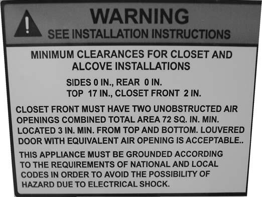
3 Important Information... 2 Important Safety Information... 4 General Information Model Identification... 8 Serial Label Location... 8 Model Nomenclature... 9 Troubleshooting Troubleshooting General Symptoms Component Testing Information Component Testing Information Disassembly Procedures Door Reversal/Disassembly...16 Interior Light...17 Top Removal Drum Baffle Removal Console Removal Front Panel Removal Heater Assembly Removal Front Bulkhead Removal Moisture Sensor Removal...22 Belt Removal Belt Switch Removal Drum Removal Motor/Blower Assembly Removal Rear Bulkhead Removal...26 Rear Roller Removal...27 Gas Model Disassembly Procedures Igniter Removal Burner Removal...28 Appendix A Installation Instructions Appendix B Use And Care Maytag Services Rev. 0 3
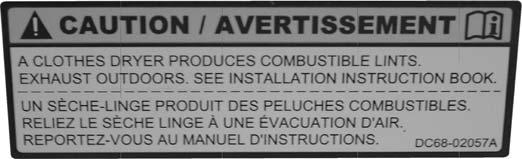
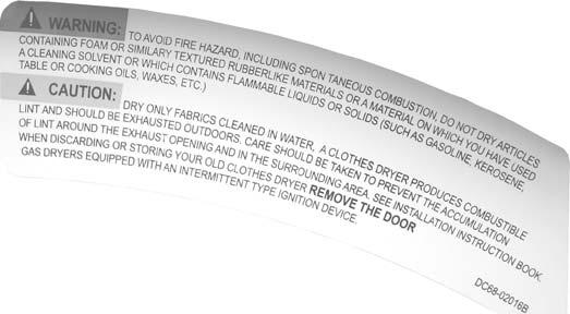
4 Important Safety Information! WARNING To avoid risk of fire, electric shock, serious injury, or death when using your dryer, follow these basic precautions: 1. Read all instructions before using dryer. 2. Install dryer according to Installation Instructions. Refer to the Grounding Instructions in the Installation Instructions for proper grounding of the dryer. 3. Do not dry articles that have been cleaned in, washed in, soaked in, or spotted with gasoline, dry-cleaning solvents, or other flammable or explosive substances. Vapors could ignite or explode. 4. Do not use dryer to dry clothes which have traces of any flammable substance, such as vegetable oil, cooking oil, machine oil, flammable chemicals, thinner, etc., or anything containing wax or chemicals, such as mops and cleaning cloths. Flammable substances may cause fabric to catch fire by itself. 5. Do not store or use gasoline or other flammable vapors and liquids near this or any other appliance. 6. Do not allow children to play on or in dryer. Close supervision of children is necessary when dryer is used near children, a safety rule for all appliances. 7. Before dryer is removed from service or discarded, remove doors to drying compartment. 8. Do not reach into dryer if cylinder is revolving. 9. Do not install or store dryer where it will be exposed to water and/or weather. 10.Do not tamper with dryer controls. 11. Do not repair or replace any part of dryer or attempt any service, unless specifically recommended in user-maintenance instructions or in published user-repair instructions that you understand and have skills to carry out, if you are a consumer. 12.To reduce risk of electric shock or fire, do not use extension cords or adapters to connect dryer to electrical power source. 13.Use the dryer only for its intended purpose, drying clothes. 14. Always disconnect dryer from electrical supply before attempting any service. Disconnect power cord by grasping the plug, not the cord. 15.Do not use heat to dry articles containing foam rubber or similarly textured rubberlike materials. 16. Always clean the lint filter after every load. A layer of lint in the filter reduces drying efficiency and prolongs drying time. 17. Use only fabric softeners or products to eliminate static that are appropriate for automatic dryers. 18. Keep your dryer in good condition. Bumping or dropping dryer can damage safety features. If damage occurs, have dryer checked by qualified service technician. 19. Replace worn power cords and/or loose plugs. 20. Do not tumble fiberglass curtains and draperies unless the label says it can be done. If they are dried, wipe out the cylinder with a damp cloth to remove particles of fiberglass. 21. Always read and follow manufacturer s instructions on packages of laundry aids. Heed all warnings or precautions. To reduce risk of poisoning or chemical burns, keep products away from children at all times, preferably, in a locked cabinet. 22. Never operate dryer with guards and/or panels removed. 23.Do not operate dryer with missing or broken parts. 24. Do not bypass safety devices. 25. Keep area around the exhaust opening and adjacent surrounding areas free from accumulation of lint, dust, and dirt. 26. Interior of dryer and exhaust duct should be cleaned periodically by qualified service personnel. 27. Dryer will not operate with loading door open. DO NOT bypass door safety switch by permitting dryer to operate with door open. Dryer will stop tumbling when door is opened. Do not use dryer if it does not stop tumbling when door is opened or starts tumbling without pressing or turning the START mechanism. Remove the dryer from use and call the service person. 28. Remove laundry immediately after the dryer stops. 29.ALWAYS follow the fabric care instructions supplied by the garment manufacturer. Save These Instructions Rev Maytag Services
5 Important Safety Information Electrical Service Information Electrical Dryers 240 VAC, 60 Hz, 30 Amps, 3 wire or 4 wire installations Gas Dryers 120 VAC, 60 Hz, 15 Amps, 3 wire installations About Ground Wires In the event of an electrical short circuit, a ground wire reduces the risk of electric shock by providing an escape wire for the electric current. Standard accepted color coding for ground wires is green or green with a yellow stripe. Grounding wires and wires colored like grounding wires are NOT to be used as current carrying conductors.! WARNING To reduce the risk of fire, electric shock, serious injury or death, all wiring and grounding must conform with the latest edition of the National Electric Code, or the Canadian Electrical Code, and such local regulations as might apply. It is the customer s responsibility to have the wiring and fuses checked by a qualified electrician to make sure your home has adequate electrical power to operate the dryer.! WARNING To avoid risk of personal injury or death due to electrical shock: Observe all local codes and ordinances. Disconnect electrical power to unit before servicing. Ground appliance properly. Check with a qualified electrician if you are not sure this appliance is properly grounded. DO NOT ground to gas line. DO NOT ground to cold water pipe if pipe is interrupted by plastic, nonmetallic gaskets, or other insulating (nonconducting) materials. DO NOT modify plug on power cord. If plug does not fit electrical outlet, have proper outlet installed by qualified electrician. DO NOT have a fuse in the neutral or ground circuit. A fuse in the neutral or ground circuit could result in an electrical shock. DO NOT use an extension cord with this appliance. DO NOT use an adapter plug with this appliance. DO NOT pinch power cord.! WARNING To reduce the risk of fire and exposure to combustion gases, the dryer MUST be exhausted to the outdoors. DO NOT exhaust dryer air into a window well, gas vent, chimney or enclosed, unventilated area, such as an attic, wall, ceiling, crawl space under a building or concealed space of a building. Gas Dryer Power Supply This equipment MUST be grounded. In the event of an electrical short circuit, grounding reduces the risk of electric shock by providing an escape wire for the electrical current. This unit is equipped with a cord having a grounding wire with a grounding plug. The plug must be plugged into an outlet that is properly installed and grounded. Consult a qualified electrician or servicer if grounding instructions are not completely understood, or if doubt exists as to whether the equipment is properly grounded. Do not use an extension cord. If the product power cord is too short, have a qualified electrician install a three slot receptacle. This unit should be plugged into a separate 60 hertz circuit with the electrical rating as shown on the serial plate. Proper Grounding and Polarization for 120 Volts Wall Outlets For the safety of our customers and the service technician ALL Amana gas dryers have a three prong power cord and MUST be connected to a properly polarized and grounded wall outlet. This information was written for those who do not understand grounding and polarization of a wall outlet. A 120 VAC wall outlet must always be wired as shown below. Neutral side Round grounding prong L V.A.C. Ground V.A.C. Neutral Explanation Polarization This means that the larger slot must be neutral and the small slot must be hot (live). Mispolarized The outlet is miswired so that the larger slot is hot (live) and the smaller slot is neutral. Grounded This means the round hole connection is connected to ground through a connection to the main power panel. Ungrounded The round hole connection is not connected to a ground and/or the main power panel Maytag Services Rev V.A.C.


6 Important Safety Information Gas Connection Information! WARNING To avoid death, personal injury or property damage, from fire or explosion, information in this manual must be followed exactly. Do not store or use gasoline or other flammable vapors and liquids in the vicinity of this or any other appliance. WHAT TO DO IF YOU SMELL GAS Do not try to light any appliance. Do not touch any electrical switch; do not use any phone in your building. Immediately call your gas supplier from a neighbor s phone. Follow the gas supplier s instructions. If you cannot reach your gas supplier, call the fire department. Installation and service must be performed by a qualified installer, service agency or the gas supplier.! WARNING To reduce the risk of fire and exposure to combustion gases, the dryer MUST be exhausted to the outdoors. DO NOT exhaust dryer air into a window well, gas vent, chimney or enclosed, unventilated area, such as an attic, wall, ceiling, crawl space under a building or concealed space of a building Rev Maytag Services

7 Important Safety Information 2005 Maytag Services Rev. 0 7
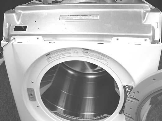
8 General Information Model Identification Complete registration card and promptly return. If registration card is missing: For Maytag product call or visit the Web Site at For product in Canada call or visit the Web Sites at or When contacting provide product information located on rating plate. Record the following: Model Number: Manufacturing Number: Serial or S/N Number: Date of purchase: Dealer s name and address: Service Keep a copy of sales receipt for future reference or in case warranty service is required. To locate an authorized servicer: For Maytag product call or visit the Web Site at For product in Canada call or visit the Web Site at Warranty service must be performed by an authorized servicer. We also recommend contacting an authorized servicer, if service is required after warranty expires. Parts and Accessories Purchase replacement parts and accessories over the phone. To order accessories for your product call: For Maytag product call or visit the Web Site at For product in Canada call or visit the Web Sites at or Extended Service Plan We offer long-term service protection for this new oven. Dependability Plus SM Extended Service Plan is specially designed to supplement Maytag s strong warranty. This plan covers parts, labor, and travel charges. Call for information. Serial Label is located in the lower center of the door opening and back panel Rev Maytag Services
9 General Information 27 Dryer Nomenclature M D E A Y W Brand M Maytag Color W White M Platinum Product Type DE Dryer Electric DG Dryer Gas Listing W 120V-60hz Y 240V-60hz Z Canada 240V-60hz Y V / Hz Feature Content 9700 Feature Package Troubleshooting Guide is Located on the back of the unit. Marketing Code This identifies which version of production the unit is Maytag Services Rev. 0 9
10 Troubleshooting Procedures! WARNING To avoid risk of electrical shock, personal injury or death, disconnect power to unit before servicing, unless testing requires power. Place dryer into Service Mode and check for diagnostic codes. See Technical Data Sheet taped to rear panel. Will Not Run Will not start or run: All wires are hooked up to their corresponding terminals. Dryer is plugged in. Blown fuse or circuit breaker. Door switch functional...door closed. Check for error code 3 (See Table for code definition). Start/Pause rotary selector dial functional. Control Board operational. Drive motor functional. Check motor winding resistance: 2.88ohms between pin #3 and 4, 3.5ohms between pin #4 and 5. Motor runs/ tumbler will not turn: Belt off or broken/damaged. Idler tension spring too weak or stretched. Idler pulley jammed or stuck. Runs a few minutes and then stops: Lint buildup around drive motor. Low voltage present. Blower impeller blocked in blower housing. Drive motor - start switch contacts stuck closed. Blows fuses or trips circuit breaker: The amperage readings are at 240 volts. One line will be 24 amps and the other line will be 21 amps. The neutral line will be at 3 amps. If the above amperages are present, then the house wiring, fuse box or circuit breaker should be suspect. Shorted heating element to housing. Incorrect wiring or a wire shorting to ground. Drive motor winding shorting to ground. Gas Models During ignition the dryer will draw X amps. With the burner ON, the dryer will draw X amps. If the dryer is drawing amperages above this, then the house wiring, fuse box or circuit breaker is suspected to be at fault. Igniter harness loose and shorted to base. Incorrect wiring or wire shorted to ground. Drive motor winding shorting to ground. Will Not Dry Will not heat (motor runs): Open heating element. Hi-Limit trips easily or is open. Regulating thermostat trips easily or is open. Membrane switch open. Check Thermistor. Will Not Dry Gas Models Poor Gas Ignition When the dryer is operated on a heat setting, the igniter should be energized and burner shall fire within 45 seconds at 120 VAC. The failure of a component in this system will usually be indicated by one of three symptoms: The igniter does not glow. If the igniter does not heat up, remove power and using an ohmmeter, check the following: Open flame sensor Open igniter Shorted booster coil Open wiring Bad motor switch ( Neutral supply) No power from control ( L1 supply) Igniter glows - No gas ignition. If the igniter heats up but the main burner flame is not ignited, remove power and using an ohmmeter, check the following: Open secondary coil Open holding coil Open wire harness Stuck flame sensor (Stuck closed) The gas is ignited but the flame goes out. If a normal ignition takes place and after a short while the flame goes out, check for the following: Radiant sensor contacts opening prematurely. Weak gas valve coil may open when stressed by higher temperatures. Weak Hi-Limit Poor venting Bad drum seals Improper drying/clothes wrinkled/ rough texture/long dry time: Lint filter is not clean. Restriction in exhaust. Outside exhaust hood damper door stuck closed. Exhaust too long, too many elbows, flex ductwork installed. Poor intake air available for the dryer. Incorrect tumbler speed. Tumbler belt slipping. Blower impeller bound; check for foreign material in blower area. Customer overloading dryer. Check clothing labels for fabric content and cycle selected. Clothes too wet due to insufficient spin out by washer. Will Not Shut Off Check Membrane Pad Rev Maytag Services
11 Troubleshooting Procedures! WARNING To avoid risk of electrical shock, personal injury or death, disconnect power to unit before servicing, unless testing requires power. Troubleshooting the electronic control circuit: Check for miswiring of the electrical connector at the electronic control board. Noisy and/or Vibration Thumping Check for loose tumbler baffle, rear tumbler roller(s) worn or misaligned, out-of-round tumbler or high weld seam on tumbler. Ticking Check for loose wire harness or object caught in blower wheel area. Scraping Check for front or rear bulkhead felt seal out of position or worn tumbler front bearings. Roaring Check for blower wheel rubbing on blower housing or bad motor bearings. Popping or squealing sound. Check for a sticky or frayed belt. Service Mode This mode provides Service Personnel the ability to verify the operation of the dryer. The Service Mode can be implemented at any time, including the middle of a dry cycle. While in the Service Mode, the Technician can start special diagnostic tests such as a System Check Mode, LED Switch/Check, Display Software version number and display diagnostic/help code listings. Enter Service Mode: Dryer must be on before Service Mode can be entered. Press Chime and Temperature Keys for 3 seconds, or until 3 beeps are heard. The machine will now be in Service Mode. Upon entry into Service Mode, the Sensor Bar Touch Data is to be displayed. Exit Service Mode Press the OFF key to exit Service Mode or repeat the Chime and Temperature sequence. Diagnostic Tests The following table lists the various tests available while in the Service Mode. Before advancing to the next test, the current test running must be terminated. Press the following keys to access: Key Press Special Test/Function Wrinkle Prevent Display list of Displays d diagnostic codes. Then rotate the Cycle Selector Knob Temperature Key Start/Pause To sequence thru the diagnostic and help codes. Display software revision number Start or pause cycle running but remain in diagnostic mode. Display the number of cycles ago the diagnostic code occurred. System Check Mode While in Service Mode, pressing the Time and Wrinkle Prevent keys for 3 seconds, will put the dryer into the System Check mode and "in" will display. The following table lists the various functions based on the keys being pressed. System Check Mode Table Key Pressed: Start/Pause rotary selector dial Rotate the Cycle Selector Knob to Delicates Rotate the Cycle Selector Knob to Sensor Dry Rotate the Cycle Selector Knob to Wrinkle Control Function Performed Cycles the motor on/off. LED s and 7 segment display flash. View current cycle temperature in Celsius. Segment display is 1 for sensor bar short, 0 for sensor bar open Rotate the Cycle Selector Knob to Time Dry View current cycle temperature in Fahrenheit Maytag Services Rev. 0 11
12 Troubleshooting Procedures! WARNING To avoid risk of electrical shock, personal injury or death, disconnect power to unit before servicing, unless testing requires power. LED/Switch Check While in Service Mode, pressing the Chime and Wrinkle Prevent keys for 3 seconds, will start a LED/Switch Test. To exit the test at any point, press the same keys again for 3 seconds or press the OFF key to exit Service Mode. Clearing Diagnostic Codes To clear the diagnostic code list press the Sensor Dry Level and Time keypads together for 3 seconds while viewing the list. The cycle count for each diagnostic code will be reset to 0, but not the machine cycle count. Perform the check by pressing the keys, which toggle the LED s on and off. All switch pads must be pressed within 5 minutes for this test to pass. PA will be displayed for five (5) seconds once all switch pads have been pressed and this test is completed. Following 10 seconds of inactivity at any point, the test will exit without any display. The Power Off switch pad must be pressed twice within thirty (30) seconds to cancel this test. Switch Wrinkle Prevent Chime Adjust Time Time Temperature Dryness Level Selector Knob Start Pause Off Action Press once Press twice Press once Press four times Press three times Press four times Rotate 1 position Press once Press once Diagnostic Codes The Diagnostic Codes are identified when the severity level of the abnormality detected is higher and service may be required. When a problem with the dryer is detected a Diagnostic Code is assigned, and can be displayed. The Control Board will not log multiple same codes per cycle; however, it will log as many Diagnostics as possible for the machine to continue running. Access Diagnostic Codes by entering the Service Mode and pressing Wrinkle Prevent. A d will be displayed. Diagnostic Codes Code Description Trigger Action Taken 1 Dryer Thermistor Short Sensed 2 Thermistor Open Sensed 3 Door Circuit Failure 4 Possible motor transistor error The Thermistor resistance is very low. The Thermistor resistance is very high Invalid state for more than 256 milliseconds If either motor transistor is seen open or shorted during startup Check for: - Clogged lint screen. - Restricted vent system. - Check Thermistor resistance. Check for: - Low ambient temperature in room (Below 50ºF/10ºC). - Outside vent damper is stuck open in wintertime. - Loose or open wire terminals. - Check Thermistor resistance. Check for: - Loose or open wire terminals in Door Sense circuit. Check for: - Loose connections in motor circuit. - Run System Check Mode and check the motor relay function. - If relay functions, disregard the diagnostic code. - If relay does not function, replace machine control board. Rotate the Cycle Selector Knob in either direction to step through the list of codes one code at a time. Once an initial direction is selected by the user (either Clockwise or Counterclockwise), subsequent movements of the knob in the same direction will show older codes. If the user changes direction and turns the knob in the opposite direction, the more recent code will be displayed. While a diagnostic code is displayed, if the Start/Pause button in the center of the Rotary Cycle Selector is pressed and held, the machine will display the number of cycles ago the diagnostic code occurred. When the Start/Pause button is released, the diagnostic code is again displayed Rev Maytag Services
13 Troubleshooting Procedures! WARNING To avoid risk of electrical shock, personal injury or death, disconnect power to unit before servicing, unless testing requires power. Code Description Trigger Action Taken 8 Stuck Key A key is sensed to be pressed more than 75 seconds, the key shall be assumed to be stuck. 10 No Wet Clothes Sensor bar detects no wet clothes while a Sensor Dry Cycle Run membrane pad check and replace console w/membrane pad if necessary. Check for: - Running dryer with no wet clothes in sensor dry cycle Display Fault/Error Codes Display Description Trigger Action Taken FE dc Power source frequency Error Door Circuit Failure Invalid power source Frequency Invalid state for more than 256 milliseconds Check for: - Not using regular power source frequency - Invalid power frequency sense circuit Check for: - Loose or open wire terminals in Door Sense circuit. - Check for diagnostic code 3 ts Dryer Thermistor Short Sensed The Thermistor resistance is very low. Check for: - Clogged lint screen. - Restricted vent system. - Check Thermistor resistance. - Check for diagnostic code 1 he Heater Error Invalid heating temperature in running the dryer Check for: - Restricted vent system. - Check Thermistor resistance. do Door Open Running the dryer with door open Check for: - Close the door, and run the dryer - Loose or open wire terminals in Door Sense circuit. - Check for diagnostic code Maytag Services Rev. 0 13

14 Component Testing Information! WARNING To avoid risk of electrical shock, personal injury or death, disconnect power to unit before servicing, unless testing requires power. Illustration Component Test Procedure Results Thermistor Unplug harness connector and test from wire insertion side. Pin #2 and Pin #6 of CN F/25 C Door Switch Light Unplug connectors and test switch terminals. Door open terminals COM to NC/ 1 to 3 Door open terminals COM to NO/1 to 2 Door closed terminals COM to NC/ 1 to 3 Door closed terminals COM to NO/ 1 to 2 Unplug connectors and test switch terminals. Check across terminals Infinity Less than 1 ohm Infinity Less than 1 ohm 80 to 100 ohms Belt Switch Motor Unplug connectors and test switch terminals. Check across terminals switch closed Check across terminals switch open Unplug harness connector and test motor circuits. Pin #4 and Pin #5 (Windings) Pin #1 and Pin #2 (Centrifugal switch) Less than 1 ohm Infinity 2 ohms Open Thermostat 185 F/85 C 25A Unplug connectors and test Thermostat terminals. Check across terminals Less than 1 ohm Hi Limit 210 F/99 C 25A Unplug connectors and test Thermostat terminals. Check across terminals Less than 1 ohm Thermal Cut Off Unplug connectors and test Thermostat terminals. Check across terminals Less than 1 ohm Heater Element Unplug connectors and test Heater terminals 10 ohms Rev Maytag Services


. Check across terminals #1 and #2 (Holding Coil). Check across terminals #2 and #3 (Both coils in series).")
15 Component Testing Information! WARNING To avoid risk of electrical shock, personal injury or death, disconnect power to unit before servicing, unless testing requires power. Illustration Component Test Procedure Results Sensor Bars Unplug harness connector and test from wire insertion side. Pin #4 to Pin # 5 of CN6 Infinity dry load 190ohms ± 10% wet load Radiant Sensor Unplug connectors and test sensor terminals. Closed TH2 Safety Thermostat Unplug connectors and test Thermostat terminals. Less than 1ohm Gas Valve Unplug connectors and test valve terminals. Check across terminals #1 and #3 (Booster Coil). Check across terminals #1 and #2 (Holding Coil). Check across terminals #2 and #3 (Both coils in series). Check across terminals #4 and #5 (Secondary Coil). 550ohms 1350ohms 1900ohms 1300ohms Motor Contacts Function 1M 2M 3M 5M 6M Start Run = Contact closed Centrifugal Switch (Motor) Gas Valve Maytag Services Rev. 0 15


16 Disassembly Procedures! WARNING Door Reversal/Disassembly 1. Disconnect power supply to unit. 2. Remove four screws and Door Strike. To avoid risk of electrical shock, personal injury or death; disconnect power to unit before servicing. 6. Remove Inner Panel. 3. Remove two screws attaching Door Hinge. 7. Remove Gasket. 4. Install Door and Strike on opposite sides or continue with Door disassembly. 5. Remove screws around perimeter of Door Inner Panel Rev Maytag Services


17 Disassembly Procedures! 8. Remove Inner Door Glass. WARNING To avoid risk of electrical shock, personal injury or death; disconnect power to unit before servicing. Interior Light 1. Disconnect power supply to unit. 2. Remove Lens screw and Lens. Bulb is a screw in base 10W 120V AC. 9. Remove outer door viewing panel. Insert screwdriver in slot to disengage latch. Top Removal 1. Disconnect power supply to unit. 2. Remove 2 10mm screws from dryer back. 3. Slide Top Cover towards the rear and lift from unit Maytag Services Rev. 0 17


18 Disassembly Procedures! WARNING To avoid risk of electrical shock, personal injury or death; disconnect power to unit before servicing. Console Removal 1. Disconnect power supply to unit. 2. Remove Top Cover. 3. Remove two screws mounting the Heater PCB Board. 4. Disconnect the black and white connectors. Drum Baffle Removal 1. Disconnect power supply to unit. 2. Remove Top Cover. 3. Remove four screws located at the sound dampening seem. 5. Remove four screws attaching Console to washer Rev Maytag Services


19 Disassembly Procedures! WARNING To avoid risk of electrical shock, personal injury or death; disconnect power to unit before servicing. 6. Rotate Console down and remove from dryer. Front Panel Removal 1. Disconnect power supply to unit. 2. Remove Top Cover. 3. Remove Console. 4. Remove four screws attaching Front Panel to dryer. 5. Remove two screws in the door area. 6. Pull Front Panel forward and disconnect the Interior Light harness. Heater Assembly Removal 1. Disconnect power supply to unit. 2. Remove Top Cover. 3. Remove Console. 4. Remove Front Cover. 5. Remove Heater Assembly retaining screw. 7. Lift the Front Panel off the three tabs across the bottom and remove Maytag Services Rev. 0 19


20 Disassembly Procedures! WARNING To avoid risk of electrical shock, personal injury or death; disconnect power to unit before servicing. 6. Slide Heater Assembly out the front of dryer.. 8. Reinstall by aligning the tabs on the back bulkhead with the notches in the Heater Assembly. 7. Remove the wiring terminals from the Heater Assembly Rev Maytag Services


21 Disassembly Procedures! WARNING To avoid risk of electrical shock, personal injury or death; disconnect power to unit before servicing. Front Bulkhead Removal 1. Disconnect power supply to unit. 2. Remove Top Cover. 3. Remove Console. 4. Remove Front Panel. 5. Remove screws retaining Console Back Cover. 6. Disconnect Interior Light wiring harness. 8. Remove four Bulkhead retaining screws 7. Disconnect Moisture Sensor wiring harness Maytag Services Rev. 0 21


22 Disassembly Procedures! WARNING To avoid risk of electrical shock, personal injury or death; disconnect power to unit before servicing. 9. Lift Bulkhead from Cabinet and remove. 6. Remove sensor attachment screw. Belt Removal 1. Disconnect power supply to unit. 2. Remove Top Cover. 3. Remove Console. 4. Remove Front Panel. 5. Remove belt from Idler Pulley Moisture Sensor Removal 1. Disconnect power supply to unit. 2. Remove Top Cover. 3. Remove Console. 4. Remove Front Panel. 5. Disconnect Moisture Sensor wire harness Rev Maytag Services


23 Disassembly Procedures Pull Idler Pulley! WARNING To avoid risk of electrical shock, personal injury or death; disconnect power to unit before servicing. Drum Removal 1. Disconnect power supply to unit. 2. Remove Top Cover. 3. Remove Console. 4. Remove Front Panel. 5. Remove Console Back Cover. 6. Remove Front Bulkhead. 7. Remove belt from Idler Pulley. 8. Grasp the Drum with one hand and the belt with the other. Lift the Drum and slide out the front. Carefully spread the cabinet as needed to gain additional clearance. Belt Switch Removal 1. Disconnect power supply to unit. 2. Remove five screws retaining Vent Tube cover. 3. Remove Belt Switch mounting screw. Belt Switch Motor/Blower Assembly Removal 1. Disconnect power supply to unit. 2. Remove Top Cover. 3. Remove Console. 4. Remove Front Panel. 5. Remove Console Back Cover. 6. Remove Belt from Idler Pulley. 7. Remove Drum. 8. Remove the two screws securing the Blower Intake Panel to the Blower Housing. Remove Blower Intake Panel Maytag Services Rev. 0 23


24 Disassembly Procedures! WARNING To avoid risk of electrical shock, personal injury or death; disconnect power to unit before servicing. 10.Remove the blower attachment screw under the Thermistor. 11. Remove two screws attaching the motor bracket to the base. 9. Removed the screw at the bottom of the blower housing Rev Maytag Services


25 Disassembly Procedures! WARNING To avoid risk of electrical shock, personal injury or death; disconnect power to unit before servicing. 12.Disconnect the Motor wire harness and the two wires to the belt switch. 13.Slide the Motor Blower Assembly toward the heater and lift to disengage the tabs on the motor from the slots in the base. NOTE: A wrench can be placed on both ends of the Motor Output Shaft. 15.Remove Blower Wheel. 14.Remove the 14mm nut securing the blower wheel to the shaft. The nut is a left hand thread. 16.Remove the three screws securing the blower housing to the motor bracket Maytag Services Rev. 0 25


26 Disassembly Procedures! WARNING To avoid risk of electrical shock, personal injury or death; disconnect power to unit before servicing. 17.Remove the three screws securing the blower housing to the motor bracket. Rear Bulkhead Removal 1. Disconnect power supply to unit. 2. Remove Top Cover. 3. Remove Console. 4. Remove Front Panel. 5. Remove Console Back Cover. 6. Remove Belt from Idler Pulley. 7. Remove Drum. 8. Remove 7 screws from the back. 18.Use a wide blade screwdriver to pop off the motor retention clamps. 9. Lift the rear bulkhead off the right and left side hangers Rev Maytag Services


27 Disassembly Procedures! WARNING To avoid risk of electrical shock, personal injury or death; disconnect power to unit before servicing. Rear Roller Removal 1. Disconnect power supply to unit. 2. Remove Rear Bulkhead. 3. Remove Roller Keeper and nut. Gas Model Disassembly Igniter Removal 1. Disconnect power supply to unit. 2. Remove Top Cover. 3. Remove Console. 4. Remove Front Panel. 5. Loosen the single screw attaching the igniter to the Burner Assembly. Slide the Igniter back and remove Maytag Services Rev. 0 27


28 Disassembly Procedures! WARNING To avoid risk of electrical shock, personal injury or death; disconnect power to unit before servicing.! WARNING To avoid risk of personal injury or death; shut off gas supply to unit before servicing Burner Assembly. NOTE: The Igniter Bar is fragile. Be careful not to damage Igniter when removing Burner Assembly. Burner Removal 1. Disconnect power supply to unit. 2. Shut off gas supply. 3. Disconnect gas line. 5. Remove the two screws attaching the housing to the burner bracket. The screws are recessed from view. 6. Slide Burner Assembly from dryer. 4. Remove two screws securing burner to bracket Rev Maytag Services
29 Appendix A 2005 Maytag Services Rev. 0 29
30 Rev Maytag Services
31 2005 Maytag Services Rev. 0 31

32 Rev Maytag Services
33 2005 Maytag Services Rev. 0 33
34 Rev Maytag Services

35 2005 Maytag Services Rev. 0 35

36 Rev Maytag Services

37 2005 Maytag Services Rev. 0 37
38 Rev Maytag Services
39 2005 Maytag Services Rev. 0 39
40 Rev Maytag Services

41 2005 Maytag Services Rev. 0 41
42 Appendix B Rev Maytag Services

43 2005 Maytag Services Rev. 0 43
44 Rev Maytag Services
45 2005 Maytag Services Rev. 0 45
46 Rev Maytag Services
47 2005 Maytag Services Rev. 0 47

48 Rev Maytag Services
49 2005 Maytag Services Rev. 0 49
50 Rev Maytag Services
51 2005 Maytag Services Rev. 0 51
52 Rev Maytag Services
53 2005 Maytag Services Rev. 0 53

54 Rev Maytag Services
55 2005 Maytag Services Rev. 0 55
56 Rev Maytag Services
57 2005 Maytag Services Rev. 0 57

58 Rev Maytag Services
! WARNING To avoid risk of electrical shock, personal injury or death; disconnect power before servicing, unless testing requires power.
 27 Gas Dryer Technical Information MDG9700A * Due to possibility of personal injury or property damage, always contact an authorized technician for servicing or repair of this unit. Refer to Service Manual
! WARNING To avoid risk of electrical shock, personal injury or death; disconnect power to dryer before servicing, unless testing requires power.
 27 Domestic Dryer Technical Information MDE6700A*, MDG6700A* Due to possibility of personal injury or property damage, always contact an authorized technician for servicing or repair of this unit. Refer
! WARNING To avoid risk of electrical shock, personal injury or death; disconnect power before servicing, unless testing requires power.
 27 Electric Dryer Technical Information MDE9700A * Due to possibility of personal injury or property damage, always contact an authorized technician for servicing or repair of this unit. Refer to Service
! WARNING To avoid risk of electrical shock, personal injury or death; disconnect power to dryer before servicing, unless testing requires power.
 Electric Dryer Technical Information CDG4205A* Due to possibility of personal injury or property damage, always contact an authorized technician for servicing or repair of this unit. Refer to Service Manual
! WARNING To avoid risk of electrical shock, personal injury or death; disconnect power to dryer before servicing, unless testing requires power.
 Electric Dryer Technical Information CDE4205A* Due to possibility of personal injury or property damage, always contact an authorized technician for servicing or repair of this unit. Refer to Service Manual
Service. Compact Dryer MDE2400AY*
 Service This manual is to be used by qualified appliance technicians only. Maytag does not assume any responsibility for property damage or personal injury for improper service procedures done by an unqualified
Test/Function Wrinkle release. Display list of diagnostic codes. Then press Temperature (^) - 13 Key. To sequence thru the diagnostic and help codes.
 - 13 Key. To sequence thru the diagnostic and help codes.") Trouble Shooting! WARNING To avoid risk of electrical shock, personal injury, death, disconnect power to washer befe servicing, unless testing requires it. Troubleshooting Guide Maytag Neptune LED Gas
Trouble Shooting! WARNING To avoid risk of electrical shock, personal injury, death, disconnect power to washer befe servicing, unless testing requires it. Troubleshooting Guide Maytag Neptune LED Gas
CLOTHES DRYER Technical Information
 CLOTHES DRYER Technical Information Due to possibility of personal injury or property damage, always contact an authorized technician for servicing or repair of this unit. Refer to Service Manual (DV456*,DV422*,DV400*)
An occurrence of an Error will make a sound of error melody for 5sec and continuously show one of the Error Displays from the following errors.
 4. Troubleshooting 4-1. Error items and diagnostic codes An occurrence of an Error will make a sound of error melody for 5sec and continuously show one of the Error Displays from the following errors.
CLOTHES DRYER Technical Information
 CLOTHES DRYER Technical Information IMPORTANT SAFETY NOTICE For Technicians only This service data sheet is intended for use by persons having electrical, electronic, and mechanical experience and knowledge
 SECTION 9 - DRYER CONTROLS OVERVIEW... 9-1 DRYER CONTROLS OVERVIEW... 9-1 BASIC CONTROL BOARD PHILOSOPHY FOR BOTH DRYERS... 9-1 BASIC MACHINE OPERATION... 9-2 LED DRYER CONTROL SELECTIONS... 9-3 DRYER
Commercial Single and Stack Dryers
 This manual is to be used by qualified appliance technicians only. Maytag does not assume any responsibility for property damage or personal injury for improper service procedures done by an unqualified
Neptune DC MCE8000AY MCG8000AW
 This manual is to be used by qualified appliance technicians only. Maytag does not assume any responsibility for property damage or personal injury for improper service procedures done by an unqualified
Fast Track Troubleshooting
 Fast Track Troubleshooting Models: DV5471AE DV5471AG NOTICE: All Dryers Parts Change 6/2010: Motor Pulley, page 5; Blower Housing, page 4 IMPORTANT SAFETY NOTICE For Technicians Only This service data
Fast Track Troubleshooting
 Fast Track Troubleshooting Models: DV203*** DV206*** DV209*** DV218*** DV219*** DV306*** DV316*** DV317*** DV326*** DV328*** DV337*** DV338*** DV3C6*** Display IMPORTANT SAFETY NOTICE For Technicians Only
Drying Tumblers. Troubleshooting. 120 Pound Capacity 170 Pound Capacity. Refer to Page 5 for Model Numbers. Part No August 2007
 HIGH LOAD READY MEDIUM TEMPERATURE LOW LOW AIR FLOW NON REV REV PUSH TO START 10 5 15 0 50 40 60 0 30 10 20 Drying Tumblers 120 Pound Capacity 170 Pound Capacity Page 5 for Model Numbers Troubleshooting
TECH SHEET - DO NOT DISCARD PAGE
 TECH SHEET - DO NOT DISCARD PAGE 1 3. If this test mode has been entered successfully, all indicators on the console are illuminated for 5 seconds with 8:88 showing in the Estimated Time Remaining three-digit
Fast Track Troubleshooting
 Models: DV431AEP DV431AEW DV431AGP DV431AGW NOTICE: 8/1/11 Parts changes see bulletins for serial breaks: motor, motor relay, wiring harness, & main PCB All Dryers Parts Change 6/2010: Motor Pulley, page
Installation Instructions
 Installation Instructions for Dryers Inside... Dimensions... Before You Start... 4 Installing the Dryer... 5 Installer Checklist... Back Cover Date Purchased Model Number Serial Number Keep these instructions
THE READY RACK 2 GEAR PPE DRYING CABINET. Operator s Manual & Installation Guide. Installation/Operation/Maintenance/Part Number I
 THE READY RACK 2 GEAR PPE DRYING CABINET Operator s Manual & Installation Guide Installation/Operation/Maintenance/Part Number 820220I Copy right 2016 Forward We are pleased that you have selected a Ready
! WARNING To avoid risk of electrical shock, personal injury or death; disconnect power to washer before servicing, unless testing requires power.
 27 Front Load Washer - Technical Information MAH6700A* Due to possibility of personal injury or property damage, always contact an authorized technician for servicing or repair of this unit. Refer to Service
Installation Instructions Dual Fuel Ranges
 Installation Instructions Dual Fuel Ranges E30DF74EPS E36DF76EPS E48DF76EPS 5995447082 2 Safety IMPORTANT SAFETY INSTRUCTIONS Safety Precautions Do not attempt to install or operate your unit until you
TECH SHEET DO NOT DISCARD PAGE 1. If unsuccessful entry into diagnostic mode, actions can be taken for specific indications:
 TECH SHEET DO NOT DISCARD PAGE 1 WARNING Electrical Shock Hazard Disconnect power before servicing. Replace all parts and panels before operating. Failure to do so can result in death or electrical shock.
Service. Vent Hoods November Maytag Services
 Service This manual is to be used by qualified appliance technicians only. Maytag does not assume any responsibility for property damage or personal injury for improper service procedures done by an unqualified
Installation Instructions
 Instructions for Stacked Dryers Original Instructions Keep These Instructions for Future Reference. (If this machine changes ownership, this manual must accompany machine.) www.speedqueen.com Part No.
Installation Instructions
 Installation Instructions Before you begin... 2 Location... 2 Recommended grounding instructions... 2 Electrical requirements... 2 Exhaust requirements... 3 Water supply and drain requirements... 3 Please
Installation Electric Dryers Instructions 01
 Installation Electric Dryers Instructions 01 Questions? Call 800.GE.CARES (800.432.2737) or visit our Web site at: GEAppliances.com This is the safety alert symbol. This symbol alerts you to potential
27" Gas Dryer MODELS: MGDB950YW3 (White) MGDB950YG3 (Cosmetallic) 05/31/ Maytag Part No. W Rev. A
 MGDB950YG3 (Cosmetallic) 05/31/ Maytag Part No. W Rev. A") 27" Gas Dryer MODELS: MGDB950YW3 (White) MGDB950YG3 (Cosmetallic) 05/31/2013 2013 Maytag Part W10617393 Rev. A TOP AND CONSOLE PARTS 05/31/2013 2 Part W10617393 Rev. A TOP AND CONSOLE PARTS Part Description
27" Gas Dryer MODELS: MGDB950YW3 (White) MGDB950YG3 (Cosmetallic) 05/31/2013 2013 Maytag Part W10617393 Rev. A TOP AND CONSOLE PARTS 05/31/2013 2 Part W10617393 Rev. A TOP AND CONSOLE PARTS Part Description
PUREPOWER SERIES CENTRAL VACUUM POWER UNITS PP500, PP600 & PP650
 USER GUIDE PUREPOWER SERIES CENTRAL VACUUM POWER UNITS PP500, PP600 & PP650 AB0039 FOR RESIDENTIAL USE ONLY!! MODELS SFDB-DQ, SFDB-DR AND SFDB-DS 30042509E IMPORTANT SAFETY INSTRUCTIONS SAVE THESE INSTRUCTIONS
27 ELECTRIC & GAS DRYERS
 CONSUMER SERVICES TECHNICAL EDUCATION GROUP PRESENTS L-63 27 ELECTRIC & GAS DRYERS JOB AID Part No. 4322260 I INTRODUCTION This Job Aid, 27 ELECTRIC & GAS DRYERS, (Part No. 4322260), provides specific
TOP AND CONSOLE PARTS
 TOP AND CONSOLE PARTS 27" ELECTRIC DRYER 6 12 Printed in U.S.A. (GG)(bay) 1 Part No. Rev. A TOP AND CONSOLE PARTS 1 Literature Parts W10392124 Installation, Diagnostic Guide W10388780 Guide, Use & Care
Installation Instructions T 9822 Gas Dryer. en - US, CA. To prevent accidents
 Installation Instructions T 9822 Gas Dryer To prevent accidents en - US, CA and appliance damage read these instructions before installation or use. M.-Nr. 07 431 110 2 WARNING For your safety the information
Technical Service Guide
 GE Consumer & Industrial Technical Service Guide December 2006 GE DRYER DSXH47EG DSXH47GG 31-9148 GE Appliances General Electric Company Louisville, Kentucky 40225 1 IMPORTANT SAFETY NOTICE The information
User's Manual. Exhaust Type Tumble Dryer HLP140E. Please read this manual carefully before using. Retain it for future reference.
 Exhaust Type Tumble Dryer User's Manual HLP140E Please read this manual carefully before using. Retain it for future reference. Names Of The Parts Transparent Windows Door Drum Exhaust Shroud Air Intake
Stacked Clothes Dryer Nonmetered and Metered
 Stacked Clothes Dryer Nonmetered and Metered Electric and Gas Models Installation/Operation Para bajar una copia de estas instrucciones en español, visite www.comlaundry.com. D009C Keep These Instructions
NOTICE . SAFE SERVICING PRACTICES. Electric Wall Oven with Electronic Oven Control
 SERVICE DATA SHEET 318047418 (0504) Rev. A Electric Wall Oven with Electronic Oven Control NOTICE This service data sheet is intended for use by persons having electrical and mechanical training and a
Automatic Dryers. Installation. Keep These Instructions for Future Reference. (If this machine changes ownership, this manual must accompany machine.
 Automatic Dryers Installation D715I Keep These Instructions for Future Reference. (If this machine changes ownership, this manual must accompany machine.) Part No. R4 June 2007 IMPORTANT: The electrical
Dryer. User manual DV22K6800** DV22K A-00_EN (US)_ indd :15:41
_ indd :15:41") Dryer User manual DV22K6800** DV22K6800-03650A-00_EN (US)_151211.indd 1 2015-12-11 7:15:41 Before installation Read through the following instructions before installing the dryer, and keep this manual
Dryer User manual DV22K6800** DV22K6800-03650A-00_EN (US)_151211.indd 1 2015-12-11 7:15:41 Before installation Read through the following instructions before installing the dryer, and keep this manual
! WARNING To avoid risk of electrical shock, personal injury or death; disconnect power to washer before servicing, unless testing requires power.
 24 Front Load Washer Technical Information MAH2400A* Due to possibility of personal injury or property damage, always contact an authorized technician for servicing or repair of this unit. Refer to Service
Installation Instructions
 Instructions for Dryers Original Instructions Keep These Instructions for Future Reference. CAUTION: Read the instructions before using the machine. (If this machine changes ownership, this manual must
Questions? Call 800.GE.CARES ( ) or visit our Web site at: GEAppliances.com In Canada, call or visit
 or visit our Web site at: GEAppliances.com In Canada, call or visit") Installation Instructions Electric Dryer 01 Questions? Call 800.GE.CARES (800.432.2737) or visit our Web site at: GEAppliances.com In Canada, call 1.800.561.3344 or visit www.geappliances.ca BEFORE YOU
Installation Instructions Electric Dryer 01 Questions? Call 800.GE.CARES (800.432.2737) or visit our Web site at: GEAppliances.com In Canada, call 1.800.561.3344 or visit www.geappliances.ca BEFORE YOU
Installation and Operation Instructions ELECTRIC FIREPLACE X56WMEF1BLK X56WMEF1WHT
 Installation and Operation Instructions ELECTRIC FIREPLACE X56WMEF1BLK X56WMEF1WHT Tool list Assembly Instructions Important Safety Instructions Listing Approvals Glass Particles Installation Instructions
GAS DRYER MODELS: (White) (Chrome Shadow) 01/28/ Sears Brands, LLC Part No. W Rev. A
 (Chrome Shadow) 01/28/ Sears Brands, LLC Part No. W Rev. A") GAS DRYER MODELS: 110.78132413 (White) 110.78133413 (Chrome Shadow) 01/28/2016 2016 Sears Brands, LLC Part W10865713 Rev. A TOP AND CONSOLE PARTS 01/28/2016 2 Part W10865713 Rev. A TOP AND CONSOLE PARTS
GAS DRYER MODELS: 110.78132413 (White) 110.78133413 (Chrome Shadow) 01/28/2016 2016 Sears Brands, LLC Part W10865713 Rev. A TOP AND CONSOLE PARTS 01/28/2016 2 Part W10865713 Rev. A TOP AND CONSOLE PARTS
GAS DRYER MODELS: MGD8200FW0 (White) MGD8200FC0 (Chrome Shadow) 05/24/ Maytag Part No. W Rev. A
 MGD8200FC0 (Chrome Shadow) 05/24/ Maytag Part No. W Rev. A") GAS DRYER MODELS: MGD8200FW0 (White) MGD8200FC0 (Chrome Shadow) 05/24/2016 2016 Maytag Part W10884161 Rev. A TOP AND CONSOLE PARTS 05/24/2016 2 Part W10884161 Rev. A TOP AND CONSOLE PARTS Part Description
GAS DRYER MODELS: MGD8200FW0 (White) MGD8200FC0 (Chrome Shadow) 05/24/2016 2016 Maytag Part W10884161 Rev. A TOP AND CONSOLE PARTS 05/24/2016 2 Part W10884161 Rev. A TOP AND CONSOLE PARTS Part Description
Questions on Installation? Call: GECARES (US) or Visit our Web site at: (US) 4" DUCT CLAMPS (2) OR 4" SPRING CLAMPS (2)
 or Visit our Web site at: (US) 4 DUCT CLAMPS (2) OR 4 SPRING CLAMPS (2)") Installation Instructions Questions on Installation? Call: 1-800-GECARES (US) or Visit our Web site at: www.geappliances.com (US) Electric Dryer 49 37 BEFORE YOU BEGIN Read these instructions completely
Installation Instructions Questions on Installation? Call: 1-800-GECARES (US) or Visit our Web site at: www.geappliances.com (US) Electric Dryer 49 37 BEFORE YOU BEGIN Read these instructions completely
Clothes Dryer Nonmetered and Metered
 Clothes Dryer Nonmetered and Metered Electric and Gas Models Installation/Operation D677I Keep These Instructions for Future Reference. (If this machine changes ownership, this manual must accompany machine.)
27" GAS DRYER MODELS: MGD7100DW0 (White) MGD7100DC0 (Chrome Shadow) 05/08/ Maytag Part No. W Rev. A
 MGD7100DC0 (Chrome Shadow) 05/08/ Maytag Part No. W Rev. A") 27" GAS DRYER MODELS: MGD7100DW0 (White) MGD7100DC0 (Chrome Shadow) 05/08/2014 2014 Maytag Part W10712329 Rev. A TOP AND CONSOLE PARTS 05/08/2014 2 Part W10712329 Rev. A TOP AND CONSOLE PARTS Part Description
27" GAS DRYER MODELS: MGD7100DW0 (White) MGD7100DC0 (Chrome Shadow) 05/08/2014 2014 Maytag Part W10712329 Rev. A TOP AND CONSOLE PARTS 05/08/2014 2 Part W10712329 Rev. A TOP AND CONSOLE PARTS Part Description
Clothes Dryer. Keep These Instructions for Future Reference. (If this machine changes ownership, this manual must accompany machine.
 Clothes Dryer Nonmetered and Metered Electric and Gas Models Installation/Operation D677I Keep These Instructions for Future Reference. (If this machine changes ownership, this manual must accompany machine.)
Washer-Extractor. Troubleshooting. Cabinet Hardmount Mechanical Timer Refer to Page 8 for Model Numbers.
 Washer-Extractor Cabinet Hardmount Mechanical Timer Refer to Page 8 for Model Numbers Troubleshooting CHM1624C www.comlaundry.com Part No. F232202R3 November 2011 Table of Contents Safety Information...3
29" GAS DRYER MODELS: MGD7000AW1 (White) MGD7000AG1 (Cosmetallic) 07/02/ Maytag Part No. W Rev. A
 MGD7000AG1 (Cosmetallic) 07/02/ Maytag Part No. W Rev. A") 29" GAS DRYER MODELS: MGD7000AW1 (White) MGD7000AG1 (Cosmetallic) 07/02/2013 2013 Maytag Part W10624907 Rev. A TOP AND CONSOLE PARTS 07/02/2013 2 Part W10624907 Rev. A TOP AND CONSOLE PARTS Part Description
29" GAS DRYER MODELS: MGD7000AW1 (White) MGD7000AG1 (Cosmetallic) 07/02/2013 2013 Maytag Part W10624907 Rev. A TOP AND CONSOLE PARTS 07/02/2013 2 Part W10624907 Rev. A TOP AND CONSOLE PARTS Part Description
COMMERCIAL ELECTRIC DRYER
 COMMERCIAL ELECTRIC DRYER MODEL MDE22PNAGW0 1 10 Litho In U.S.A. (BT)(bay) c 2010 WHIRLPOOL CORPORATION Part No. Rev. B TOP AND CONSOLE PARTS WIRING HARNESS PARTS 2 TOP AND CONSOLE PARTS 1 Literature Parts
Clothes Dryer. Installation/Operation. Nonmetered and Metered. Electric and Gas Models
 Clothes Dryer Nonmetered and Metered Electric and Gas Models Installation/Operation D677I Keep These Instructions for Future Reference. (If this machine changes ownership, this manual must accompany machine.)
Installation Instructions
 Instructions for Dryers Original Instructions Keep These Instructions for Future Reference. (If this machine changes ownership, this manual must accompany machine.) www.speedqueen.com Part No. 5439R October
Installation Instructions
 Instructions for Dryers Original Instructions Keep These Instructions for Future Reference. (If this machine changes ownership, this manual must accompany machine.) www.speedqueen.com Part No. 54320R October
Installation Instructions
 Instructions for Dryers Original Instructions Keep These Instructions for Future Reference. (If this machine changes ownership, this manual must accompany machine.) www.alliancelaundry.com Part No. 514685R1
EF5802R Freestanding Electric Fireplace
 EF5802R Freestanding Electric Fireplace Installation Instructions and Homeowner's Manual WARNING! IF THE INFORMATION IN THIS MANUAL IS NOT FOLLOWED EXACTLY, A FIRE MAY RESULT CAUSING PROPERTY DAMAGE, PERSONAL
Clothes Dryer Electric and Gas Models
 Clothes Dryer Electric and Gas Models Installation/Operation DRY684C Para bajar una copia de estas instrucciones en español, visite www.comlaundry.com. Keep These Instructions for Future Reference. (If
V SERIES HDR GAS RANGES
 SERVICE MANUAL ONE POWERFUL PACKAGE V SERIES HDR GAS RANGES TOPS Open Top Hot Top Griddle Top Work Surface BASES Standard Oven Convection Oven Cabinet Base - NOTICE - This manual is prepared for use by
PUREPOWER SERIES CENTRAL VACUUM POWER UNITS PP500, PP600 & PP650
 USER GUIDE PUREPOWER SERIES CENTRAL VACUUM POWER UNITS PP500, PP600 & PP650 AB0039 FOR RESIDENTIAL USE ONLY!! BROAN-NUTONE LLC; HARTFORD, WISCONSIN WWW.NUTONE.COM 1-888-336-3948 REGISTER YOUR PRODUCT ONLINE
Installation Instructions
 Instructions for Dryers Original Instructions Keep These Instructions for Future Reference. (If this machine changes ownership, this manual must accompany machine.) Part No. 514446ENR2 February 2015 Front
COMMERCIAL ELECTRIC DRYER
 COMMERCIAL ELECTRIC DRYER MODEL CEW9100VQ0 c 2012 WHIRLPOOL CORPORATION 4 12 Litho In U.S.A. (CMS) (psw) Part No. Rev. B TOP AND CONSOLE PARTS 2 TOP AND CONSOLE PARTS 1 Literature Parts W10184516 Installation
SERVICE Manual CLOTHES DRYER. Basic Model : DV435ETGJWR/A1 (GRACE-S DRYER PROJECT) Model Name : DV45H* DV42H* (DV6000/5000HA DRYER PROJECT) DV45H*
 Model Name : DV45H* DV42H* (DV6000/5000HA DRYER PROJECT) DV45H*") CLOTHES DRYER Basic Model : DV435ETGJWR/A1 (GRACE-S DRYER PROJECT) Model Name : DV45H* DV42H* (DV6000/5000HA DRYER PROJECT) SERVICE Manual CLOTHES DRYER CONTENTS 1. Safety Instructions 2. Features and
CLOTHES DRYER Basic Model : DV435ETGJWR/A1 (GRACE-S DRYER PROJECT) Model Name : DV45H* DV42H* (DV6000/5000HA DRYER PROJECT) SERVICE Manual CLOTHES DRYER CONTENTS 1. Safety Instructions 2. Features and
Installation Instructions
 Instructions for Dryers Original Instructions Keep These Instructions for Future Reference. (If this machine changes ownership, this manual must accompany machine.) www.alliancelaundry.com Part No. D5486ENR
ELECTRIC FIREPLACE OWNER S MANUAL
 ELECTRIC FIREPLACE OWNER S MANUAL MODELS EL1346C 4001358 WARNING: If the information in this manual is not followed exactly, a fire or electrical shock may result causing property damage, personal injury
Homestyle Stacked Washer/ Dryers
 Homestyle Stacked Washer/ Dryers Refer to Page 6 for Model Numbers Troubleshooting SWD452C www.comlaundry.com Part. 802848 May 2007 Table of Contents Section 1 Safety Information...3 Locating an Authorized
GAS COOKTOP INSTALLATION INSTRUCTIONS
 INSTALLATION AND SERVICE MUST BE PERFORMED BY A QUALIFIED INSTALLER. IMPORTANT: SAVE FOR LOCAL ELECTRICAL INSPECTOR'S USE. READ AND SAVE THESE INSTRUCTIONS FOR FUTURE REFERENCE. WARNING If the information
! WARNING To avoid risk of electrical shock, personal injury or death; disconnect power to washer before servicing, unless testing requires power.
 27 Front Load Washer - Technical Information MAH9700A* Due to possibility of personal injury or property damage, always contact an authorized technician for servicing or repair of this unit. Refer to Service
Home Stack Washer/Dryers
 Home Stack Washer/Dryers Refer to Page 3 for Model Numbers Parts SWD456C_806093 www.alliancelaundry.com Part No. 806093R1 December 2016 Table of Contents Title Page Parts Ordering Information... 2 Serial
DRYER USER INSTRUCTIONS
 If you need assistance or service, first see the Troubleshooting section. Additional help is available by calling our Customer experience Center at 1-800-253-1301 from anywhere in the U.S.A., or write:
Summer Breeze Heater Service Manual
 Summer Breeze Heater Service Manual RSBH RSBH-SB RSBHP Revision: 1.0 Issued: 12-18-2012 Table of Contents I. Basic Assembly and Operation A. Safety Instructions... 2 B. Grounding Instructions... 3 C.
User s Information Manual
 48AJ,AK,AW,AY020-060 Single-Package Rooftop Gas Heating Units with COMFORTLINK Controls and Scroll Compressors User s Information Manual NOTE TO INSTALLER This manual should be left with the equipment
! WARNING To avoid risk of electrical shock, personal injury or death; disconnect power before servicing.
 27 Front Load Washer Technical Information MAH8700A * Due to possibility of personal injury or property damage, always contact an authorized technician for servicing or repair of this unit. Refer to Service
Homestyle Frontload Washers
 Homestyle Frontload Washers Service Refer to Page 2 for Model Numbers FLW1515C www.comlaundry.com Part No. 801728R3 May 2007 Table of Contents Model Identification...2 Section 1 Safety Information Locating
ELECTRIC FLAT PANEL FIREPLACE HEATER
 ELECTRIC FLAT PANEL FIREPLACE HEATER Model Numbers: 80-2000A-42 OWNER S MANUAL AC 120V 60Hz 1500W WARNING Read and understand this entire owner s manual, including all safety information, before plugging
27" GAS DRYER MODELS: WGD95HEDW0 (White) WGD95HEDC0 (Chrome Shadow) 05/13/ Whirlpool Corporation Part No. W Rev.
 WGD95HEDC0 (Chrome Shadow) 05/13/ Whirlpool Corporation Part No. W Rev.") 27" GAS DRYER MODELS: WGD95HEDW0 (White) WGD95HEDC0 (Chrome Shadow) 05/13/2014 2014 Whirlpool Corporation Part W10710285 Rev. A TOP AND CONSOLE PARTS 05/13/2014 2 Part W10710285 Rev. A TOP AND CONSOLE
27" GAS DRYER MODELS: WGD95HEDW0 (White) WGD95HEDC0 (Chrome Shadow) 05/13/2014 2014 Whirlpool Corporation Part W10710285 Rev. A TOP AND CONSOLE PARTS 05/13/2014 2 Part W10710285 Rev. A TOP AND CONSOLE
Installation. Instructions. Gas Dryer. Questions? See Owner's Manual or call Amana Consumer Affairs Department DRYER DRUM
 BULT BETTER THAN T HAS TO Br nstallation nstructions Gas Dryer Keep instructions for future reference. Be sure manual stays with dryer. Questions? See Owner's Manual or call Amana Consumer Affairs Department
Installation Instructions Wall Ovens
 Installation Instructions Wall Ovens TESTED IN ACCORDANCE WITH THE LATEST EDITION OF UL858 STANDARD FOR HOUSEHOLD ELECTRIC COOKING APPLIANCES. IMPORTANT 1. Before beginning installation, please thoroughly
Dryers. Service. Home Laundry. Models LEK33A*-4350 and LGK33A*-3058 D281P
 Dryers Home Laundry Models LEK33A*-4350 and LGK33A*-3058 Service D281P Part No. 505714 November 1998 Table of Contents Section 1 Safety Information...3 Section 2 Introduction...5 Parts Ordering Information...5
USER'S MANUAL PGE Single Package Rooftop
 USER'S MANUAL PGE Single Package Rooftop Gas Heating/Electric Cooling Units Sizes 036-150 3 to 12-1/2 Tons NOTE TO INSTALLER: This manual should be left with the equipment owner. WARNING: If the information
Homestyle Stack Washer/Dryers
 Homestyle Stack Washer/Dryers Refer to Page 3 for Model Numbers Parts SWD456C_806105 www.alliancelaundry.com Part No. 806105R1 November 2015 Table of Contents Title Page Parts Ordering Information...
Please read the following installation instructions first after purchasing this product or transporting it to another location.
 0 INSTALLATION INSTALLATION Installation Overview Please read the following installation instructions first after purchasing this product or transporting it to another location. Check and choose the proper
Installation Instructions
 Instructions for Dryers Original Instructions Keep These Instructions for Future Reference. (If this machine changes ownership, this manual must accompany machine.) www.speedqueen.com Part No. D5439R2
COMMERCIAL ELECTRIC DRYER
 COMMERCIAL ELECTRIC DRYER MODEL MLE24PNAGW0 7 09 Litho in U.S.A. (BT)(bay) c 2009 WHIRLPOOL CORPORATION Part No. Rev. A LOWER CABINET AND FRONT PANEL PARTS 2 LOWER CABINET AND FRONT PANEL PARTS 1 Literature
27" GAS DRYER MODELS: 7MWGD87HEDC0 (Chrome Shadow) 08/19/ Whirlpool Corporation Part No. W Rev. A
 08/19/ Whirlpool Corporation Part No. W Rev. A") 27" GAS DRYER MODELS: 7MWGD87HEDC0 (Chrome Shadow) 08/19/2014 2014 Whirlpool Corporation Part W10738517 Rev. A TOP AND CONSOLE PARTS 08/19/2014 2 Part W10738517 Rev. A TOP AND CONSOLE PARTS 1 Literature
27" GAS DRYER MODELS: 7MWGD87HEDC0 (Chrome Shadow) 08/19/2014 2014 Whirlpool Corporation Part W10738517 Rev. A TOP AND CONSOLE PARTS 08/19/2014 2 Part W10738517 Rev. A TOP AND CONSOLE PARTS 1 Literature
Commercial Stacked Dryers Metered and Nonmetered Refer to Page 3 for Model Numbers
 Commercial Stacked Dryers Metered and Nonmetered Refer to Page 3 for Model Numbers Service www.comlaundry.com Part No. 53277R2 January 2002 Table of Contents Section 1 Safety Information Locating an Authorized
Installation Instructions
 Instructions for Topload Washers Original Instructions Keep These Instructions for Future Reference. CAUTION: Read the instructions before using the machine. (If this machine changes ownership, this manual
Questions? Call 800.GE.CARES ( ) or visit our Web site at: GEAppliances.com In Canada, call or visit
 or visit our Web site at: GEAppliances.com In Canada, call or visit") Installation Instructions Electric Dryer 01 Questions? Call 800.GE.CARES (800.432.2737) or visit our Web site at: GEAppliances.com In Canada, call 1.800.561.3344 or visit www.geappliances.ca BEFORE YOU
Installation Instructions Electric Dryer 01 Questions? Call 800.GE.CARES (800.432.2737) or visit our Web site at: GEAppliances.com In Canada, call 1.800.561.3344 or visit www.geappliances.ca BEFORE YOU
user manual Model #: BLZ-WVH-42
 user manual Model #: BLZ-WVH-42 ii Table of Contents Table of Contents 1 Safety Notice III-V 2 Diagrams 1-3 Hood Dimensions............ 1 Control Panel.............. 2 Clearance............... 3 3 Installation
DIAGNOSTIC GUIDE DISPLAY FAULT/ERROR CODES E1 THERMISTOR OPEN IMPORTANT. Activating the Diagnostic Test Mode. Test Mode Functionality
 TECH SHEET - DO NOT DISCARD PAGE 1 DIAGNOSTIC GUIDE Electrical Shock Hazard Disconnect power before servicing. Replace all panels before operating. Failure to do so can result in death or electrical shock.
Clothes Dryer. Installation/Operation. Electric and Gas Models
 Clothes Dryer Electric and Gas Models Installation/Operation Original Instructions Keep These Instructions for Future Reference. CAUTION: Read the instructions before using the machine. (If this machine
Clothes Dryer. Installation/Operation. Electric and Gas Models
 Clothes Dryer Electric and Gas Models Installation/Operation Original Instructions Keep These Instructions for Future Reference. CAUTION: Read the instructions before using the machine. (If this machine
EF5528RKD Freestanding Electric Fireplace
 EF5528RKD Freestanding Electric Fireplace Installation Instructions and Homeowner's Manual WARNING! IF THE INFORMATION IN THIS MANUAL IS NOT FOLLOWED EXACTLY, A FIRE MAY RESULT CAUSING PROPERTY DAMAGE,
Installation Instructions Remote Blowers
 Installation Instructions Remote Blowers Models: REMP3, REMP16 Suitable for use in a household cooking area. Suitable for use with solid state controls. To complete this blower, a Dacor hood assembly or
OWNER S MANUAL ELECTRIC FIREPLACE INSERT. Model No.: WESTERN (EF42D-45D) WARNING CAUTION
 WARNING CAUTION") ELECTRIC FIREPLACE INSERT Model No.: WESTERN (EF42D-45D) OWNER S MANUAL WARNING Read and understand this entire owner s manual, including all safety information, before plugging in or using this product.
ELECTRIC FIREPLACE INSERT Model No.: WESTERN (EF42D-45D) OWNER S MANUAL WARNING Read and understand this entire owner s manual, including all safety information, before plugging in or using this product.
Homestyle Stacked Washer/ Dryers
 Homestyle Stacked Washer/ Dryers Refer to Page 6 for Model Numbers Troubleshooting SWD452C www.comlaundry.com Part. 802848R2 August 2011 Table of Contents Section 1 Safety Information...3 Locating an
GAS DRYER MODELS: WGD8000DW0 (White) 03/30/ Whirlpool Corporation Part No. W Rev. C
 03/30/ Whirlpool Corporation Part No. W Rev. C") GAS DRYER MODELS: WGD8000DW0 (White) 03/30/2015 2015 Whirlpool Corporation Part W10743192 Rev. C TOP AND CONSOLE PARTS 03/30/2015 2 Part W10743192 Rev. C TOP AND CONSOLE PARTS Part Description 1 Literature
GAS DRYER MODELS: WGD8000DW0 (White) 03/30/2015 2015 Whirlpool Corporation Part W10743192 Rev. C TOP AND CONSOLE PARTS 03/30/2015 2 Part W10743192 Rev. C TOP AND CONSOLE PARTS Part Description 1 Literature
Home Stack Washer/Dryers
 Home Stack Washer/Dryers Refer to Page 3 for Model Numbers Parts SWD456C_806093 www.alliancelaundry.com Part No. 806093R4 September 2018 Table of Contents Title Page Parts Ordering Information... 2 Serial
DESIGN CLASS FUNCTION
 PROFESSIONAL QUALITY COOKING EQUIPMENT INSTALLATION MANUAL FOR PERFORMER SLIDE-IN COOK TOPS MODEL NUMBERS: AROBSCT-424, AROBSCT-242GD, AROBSCT-24X2GR, AROBSCT-430, AROBSCT-636, AROBSCT-436GD, AROBSCT-436GR,
SAFE DRINKING WATER AND TOXIC ENFORCEMENT ACT
 Installation instructions for your new Spacemaker Laundry WSM2780 Gas Before you begin Read these instructions completely and carefully. IMPORTANT OBSERVE ALL GOVERNING CODES AND ORDINANCES. Note to Installer
Installation Instructions
 Instructions for Dryers Original Instructions Keep These Instructions for Future Reference. CAUTION: Read the instructions before using the machine. (If this machine changes ownership, this manual must