Installation Manual PellX 20 & 35 kw Pellet Burner with External Auger
|
|
|
- Quentin Reed
- 6 years ago
- Views:
Transcription


1 Installation Manual PellX 20 & 35 kw Pellet Burner with External Auger SAVE THESE INSTRUCTIONS This manual is for the Installer. Important operating and maintenance instructions are included. Read, understand, and follow these instructions for safe installation and operation. This operating manual must be kept near to the boiler for the party responsible for installation, maintenance, use, and operation. Gordic Environment AB
2 Gordic Environment AB Box Vittsjö Sweden 2
3 Contents Contents 1. Safety Instructions Warnings, Cautions, and Notes General Safety Instructions for Installation, Use, and Service Safety Guidelines for Self Cleaning Safety Systems Compliance Standards Testing Technical Data Dimensions Principal Function Pellet Quality Delivery Check List Burner Parts List Precautions Boiler Chimney Pellet Burner, Hopper and Auger Installations Burner Installation Pellet Hopper Installation Pellet Auger Installation Electrical Installation Installation of the Control Box Connection of Boiler Temperature Sensor Accumulator Tank Control Main Power Supply Wiring Diagram First Start / Test Functions / Adjustment during Operation Test Functions of the Burner / Preliminary Adjustment First Start Function 9: To Load Pellet Auger Function 9: Start Up Pellet Amount Function 8: Test and Adjust Pellet Feed Rate Function 7: High Effect Fan Speed Adjustment Function 6: Maximum Run Time Function 5: Display The Boiler s Turn Off Temperature And Current Temperature Function 4: Function Test - Burner Function 4: Function Test - Control Box First Start / Adjustment during Operation Trouble Shooting Trouble Shooting Self Cleaning Repair Resetting the Overheat Protection on the Flame Trap Pipe Replacement of the Ignition Element
4 Contents 7.3 Replacement of the Combustion Air Fan Replacement of the Flame Sensor Replacement of the Triac Unit Replacement of the Program Circuit Card Index
5 Safety Instructions 1. Safety Instructions 1.1 Warnings, Cautions, and Notes The safety instructions in this manual use the following warnings and symbols: WARNING Warning indicates a hazard which, if not avoided, could result in death or serious injury and / or property damage. 1.2 General Read the safety instructions carefully before installation. Always follow the safety instructions during installation and during maintenance. Follow the safety instructions on the warning signs! Installation, operation, service, and other work must be carried out by qualified personnel in accordance with local codes and regulations. WARNING CAUTION Caution indicates a hazard which, if not avoided, might result in minor or moderate injury and property damage. NOTE Note indicates a practice or convention that should be followed in order to avoid possible damage to the unit and / or its installed equipment. Also used to indicate information which will increase the operator's understanding of the unit and / or its installed equipment. Always follow the instructions for operations and service. NOTE For personal and operational safety, use only spare parts which have been manufactured or approved by Gordic Environment AB. Use of non- Gordic spare parts will void the warranty. WARNING Children and adults should be alerted to the hazards of high surface temperatures and should stay away to avoid contact to skin and / or clothing. Young children should be carefully supervised when they are in the same room as the burner. Clothing and other flammable materials should not be placed on or near this unit. 5


6 Safety Instructions 1.3 Safety Instructions for Installation, Use, and Service WARNING The compressor, which is connected to self cleaning equipment, must be approved by a PellX Authorized Installation Contractor. The boiler room, where the pellet plant is to be installed, the chimney, and the auxiliary equipment must be in compliance with local codes and regulations. The owner / user shall read and understand this manual before installation and operation of the burner. For proper function and to avoid accidents and damage, these instructions must be followed. Wrong handling and incorrect settings can result in injury and damage and / or malfunction of the equipment. All plumbing work shall be done by certified and qualified personnel in accordance with local codes and regulations. WARNING There is high voltage inside the equipment. All electrical installation and service work shall be done by certified and qualified personnel in accordance with local codes and regulations. Do not perform electrical work unless you have the required qualifications. Perform a complete burner shutdown and disconnect the power supply prior to performing any work on the burner. Observe all guidelines with respect to installation, service, or cleaning. It is absolutely forbidden to connect the burner directly to a wall socket. Always check with your local authorities with jurisdiction (AWJ) concerning plumbing and heating code requirements for pellet burner installations. PellX requires that the burner s power supply must be controlled by a high limit (temp) manual reset device like the Honeywell L4006H1004 and a low water cut off (LWCO) device like the Taco LWCO LF. Connection of the main power supply shall be done by an authorized electrician according to the wiring diagram in the PellX 20 & 35 kw Pellet Burner with External Auger Installation Manual. The burner casing must always be mounted when the burner is connected to the main power supply. Always make sure that the burner is disconnected (unplug the main power supply cable) before performing any cleaning or maintenance. Note that the power switch on the external control box does not disconnect the main power supply. WARNING There are rotating parts inside the auger. Prior to performing any work on the auger or the pellet hopper, disconnect the power supply to the auger motor. 6
7 Safety Instructions WARNING There is a risk of burn from touching the equipment during operation. The burner casing, burner body, flange, and flame trap pipe are hot surfaces during operation. Keep children away and do not touch the equipment during operation. It is absolutely forbidden to open the boiler doors when the burner is running. Also be careful when opening the flame inspection port during operation. Do not over fire. If any external parts start to glow, you are over firing. Reduce the pellet feed rate. Over firing will void the warranty. WARNING There is risk of fire or explosion. Make sure that no flammable or liquid materials are stored in the boiler room or vicinity of the boiler. Do not use chemicals or fluids to start the burner fire. Do not burn garbage, gasoline, naphtha, engine oil, or other materials. All chimney sweeping shall be done by certified and qualified personnel in accordance with local codes and regulations. CAUTION WARNING There is danger to life from flue gas poisoning. Make sure there is adequate combustion air under all circumstances in the boiler room. If any equipment like exhaust fans, central vacuum systems, dryers, or air conditioning equipment is installed in the boiler room or adjacent areas make sure their installation does not produce negative air pressure or affects in any way the pellet burner operation. Make sure the boiler is connected to a chimney or vertical venting system in accordance with local codes and regulations. Each appliance pellet fired boiler must have its own flue and cannot be connected to a chimney flue serving any other appliance. Use only approved pellets as described in the section 1.10 Pellet Quality. Burning any other type of fuel voids the warranty. WARNING DO NOT install in a sleeping room. DO NOT connect to any air distribution duct or system. DO NOT terminate the vent in any enclosed or semi enclosed area, such as; carports, garage, attic, crawl space, under a sun deck or porch, narrow walkway or closed area, or any location that can build up a concentration of fumes such as a stairwell, covered breezeway etc. 7

8 Safety Instructions CAUTION Proper installation of this burner is necessary for safe and efficient operation. The burner must be connected to a boiler as the heating source. Installing this product improperly may result in a house fire and personal injury. Contact your local building inspector to obtain any necessary permits or inspection guidelines before installing the product. Contact local building or fire officials about restrictions and installation inspection requirements in your area. Contact your local authority (such as municipal building department, fire department, fire prevention bureau, etc.) to determine the need for a permit. A working smoke detector is required and must be installed in the same room as the burner. This installation must conform to local codes and regulations. The structural integrity of the manufactured home floor, wall, and ceiling/roof must be maintained. The PellX burner is Not approved for installation in mobile homes. Any interference or use of parts other than original spare parts provided only by PellX or its authorized representative can result in danger for the end-user and release the supplier from all kinds of responsibility for the product. This manual shall be kept intact during the lifetime of your PellX burner. 1.5 Safety Systems CAUTION It is forbidden to tamper with the safety devices or disable their function. The PellX burner system is equipped with the following safety systems: FLAME TRAP PIPE BETWEEN PELLET AUGER AND BURNER The flame trap pipe prevents back-firing into the fuel hopper. The upper part of the flame trap pipe is a plastic hose that can melt. 1.4 Safety Guidelines for Self Cleaning The maximum air pressure for the compressor s self cleaning feature is 8 Bar / 116 PSI. The main cable to the compressor and the air supply hose should not be allowed to get in contact with any surfaces of a temperature over 158 F / 70 C. Flame Trap Pipe Overheat Protection Cover Make sure that the compressor is disconnected from the burner before cleaning and maintenance. 8


9 Safety Instructions OVERHEAT PROTECTION (203 o F / 95 C) ON THE FLAME TRAP PIPE Switches off the main power supply if the burner is overheated by a back-fire. The overheat protection cover must be mounted on the burner during operation. Triac Overheat Thermostat Overheat Protection Switch - Push to Reset OVERHEAT THERMOSTAT (158 o F / 70 C) ON THE TRIAC UNIT If the electronic module (the Triac Unit) in the burner becomes exceptionally warm, the thermostat stops the feeding of pellets to the burner. When the fire goes out due to lack of fuel, the flame sensor gives a signal to the burner to make a controlled shut-down. The overheat thermostat is automatically reset when the temperature goes down to approximately 140 o F / 60 C. FLAME SENSOR The flame sensor checks that the unit is burning after the start sequence begins and during the operation mode. If the flame sensor does not see flame, the fuel feed stops and the burner is cooled down with maximum fan speed for a settled period of time before it stops. At a normal stop, the cooling down phase starts after the flame sensor does not see flame. Flame Sensor 9

10 Safety Instructions EXTRA SAFE MODE After a second flame sensor drop out during operation, a controlled shutdown of the burner is carried out. Once the flame sensor has stopped the burner, a new starting attempt is made after about 30 minutes. If the burner starts, it is only allowed to run with low effect fuel feed (65% of supplied) and at set Fan High. This operational mode reduces the temperature in the burner but also the efficiency. If the flame sensor is activated once again, restart is not allowed. ELECTRICAL FUSES The burner is equipped with two main fuses. One is located on the main power inlet of the Triac Unit. The other is located on the main power inlet of the Control Box. Each fuse is a Slow Blow fuse 4A, Ø5x20 mm, type T4AH-250 V. Fuse & Fuse Holder POWER INTERRUPTION After a power interruption, the control system records if the burner has stopped in a normal way. It moves then to the idle position or alternatively to the starting mode if there is a long power interruption. If the power interruption occurs during the burner s operation, the fan runs for a few minutes to burn residual pellets, if any, before the burner restarts normally again. NOTE The PellX pellet burner must have ample clearance in accordance to local codes. Compliance with local codes and applicable clearance requirements must be determined by the owner / user and are not the responsibility of PellX or its authorized representatives. 1.6 Compliance Standards Testing The PellX burner has been tested and listed to UL 391, ETLM 78-1, ASTM E-1509, CAN/CSA by Guardian Fire Testing Labs, Inc. Triac Unit Fuse Holder Socket 10
11 Safety Instructions 1.7 Technical Data Burner PellX 20 kw PellX 35 kw Heating Effect (Supplied) kw / 44,382-85,350 BTU kw / 102, ,560 BTU Combustion Efficiency Approximately 95% Approximately 95% Combustion Air (Used) Approximately m 3 / h Approximately m 3 / h Power Supply 120 V 60 Hz 120 V 60 Hz Electrical Effect (Ignition) 400 W 400 W Electrical Effect (Operation) 40 W 40 W Combustion Fan Adjustable Adjustable Fuses (2) 4 AMP 5mm x 20mm slow blow fuses 4 AMP 5mm x 20mm slow blow fuses Weight 15 kg / lbs 16 kg / lbs Self Cleaning Compressor: Pressure: Bar / PSI Minimum Recommended Pressure:... 6 Bar / 87 PSI Minimum Tank volume:...3 liters / 0.79 gallons Air Pressure Connection Type:...Cejn 320 (also Tema 1600, Rectus 25) Solenoid Valves (2): Electrical Connection: V 60 Hz NOTE We recommend that a low sound level compressor be used. NOTE We recommend pellets that contain ash content of less than 1 weight-% and the lowest ash melting temperature (IT) of 2372º F / 1300 C. 11
12 Safety Instructions 1.8 Dimensions Burner (mounted in mounting flange) Outside The Boiler: Depth: /8 / cm Width:...8-7/8 / cm Total height: /2 / cm Combustion Chamber Tube in the Boiler: Length:...4-1/2 / cm Diameter:...6-1/8 / cm Combustion Chamber (recommended dimensions) Depth: /8 / cm Width: / cm Height: / cm For to ease maintenance and service we recommend a free space of approximately 12 / cm of depth and 2 / 5.08 cm from the outside of the combustion chamber tube as shown in the drawings that follow. 12
13 Safety Instructions 1.9 Principal Function The PellX burner is meant to be installed in a boiler and fuelled with wood pellets. The supplied auger transports the fuel from a pellet hopper to the burner. The control box contains a microprocessor system that monitors and regulates the combustion. The supplied temperature sensor starts and stops the burner, automatically referencing the boiler temperature. A warm air element ignites the fuel. The start procedure is designed to create a quick and almost smoke free ignition. The burner starts automatically when the boiler temperature cools down to the set start temperature. It runs until the preset maximum boiler temperature (switch-off temperature) has been reached, e.g º F / C. When the boiler stops automatically, a short cooling-down and self cleaning period is initiated. The burner can be set for operation with four different start-stop differences, 50, 60, 70, or 80 F / 10, 15, 20, or 25 C. Power interruptions and disturbances are taken care of by the control system. After a power interruption, the present conditions are checked against the previous settings after which the burner restarts. When a disturbance occurs, the burner can be operated in an Extra Safe Mode (See section 1.5 Safety Systems) or if there is a safety risk, the burner switches off. As an additional option, the control box may be configured to work as an accumulator regulator. This feature allows for longer run times. This feature is enabled when an optional second temperature sensor (not included) is installed in the accumulator to shut off when the accumulator preset temperature has been reached or when the boiler has reached 194º F / 90 C, whichever occurs first. 13
14 Safety Instructions 1.10 Pellet Quality Not all wood pellets make good fuel. It is always a good idea to review the pellet s analysis and try some before committing to several tons. Higher pellet quality allows for more efficient operation. Many variables contribute to the quality of a wood pellet. Many of these have been identified and are regularly tested for by most pellet manufactures and distributors. The Pellet Fuel Institute (PFI) has a non mandatory pellet grading system that is as close to an accepted national standard as exists. PFI classifies wood pellets into four grades, Super Premium, Premium, Standard and Utility based on a series of these predictive tests. While the PellX burner works best on the Super Premium grade pellets, it is capable of running on Premium and even Standard grade when adjusted to do so. Better pellets will provide you with more efficient combustion, less maintenance, and more heat. If a pellet manufacturer chooses not to use the PFI certification program, it doesn t necessarily mean they make a poor pellet. All quality pellet manufacturer s regularly test their product and have those results available. Below are some definitions with parameters to help in determining pellet quality. Pellet Material: Pellets should be made of softwood or hardwood or some combination of the two. Pellets should smell like wood. If not, then other materials may have been used in their manufacturing process. Examples are cardboard and paper that produce excessive ash and require chemical binders to hold the pellets together. All wood pellets (100% wood) don t require binders and rely on the lignin in the wood to hold the pellets together. A few all wood pellets dropped in a glass of water should swell up quickly. If they don t swell up, this may be an indication that the pellets are not entirely made of wood. Softwood typically produces less and lighter ash and has a higher BTU pound for pound than Hardwood. Bark and stump material should also be avoided because of the concentration of impurities that can cause clinkers or sinter at high and prolonged combustion temperatures. Bark is darker and is characterised by little dark fragments that can be seen in the pellet center after breaking open the pellet or on the pellet surface. Pellet Size: A pellet diameter of 1/4 to 5/16 / 0.64 cm to 0.79 cm must be used with a maximum length of less than 1-1/2 / 3.81 cm. You should look for consistency in size. WARNING Only wood pellets are to be used with this burner. No other fuel is to be used in the burner. NEVER BURN ANY TYPE OF CORN, CHERRY PITS, STICKS OR OTHER TYPES OF FUEL IN THE BURNER. Burning wood pellets according to recommendations and the specifications set forth will assure longer burner life and lessen potential maintenance issues. Pellet Bulk Density: A bulk density of 40 to 46 lbs per cubic foot / to kg per cubic meter is the recommendation for Super Premium and Premium graded pellets. Pellet Moisture Content: The humidity of wood pellets needs to be 10% or less. Care needs to be taken that the pellets are stored in as dry a location as possible. 14
15 Safety Instructions Pellet Energy Content / BTU Value: An energy content of 7,300 to 8,500 BTU of energy per pound of pellets is a typical measure. BTU content is not a requirement for grading but is a useful test for fuel comparisons and output calculations. Pellet Ash Content: Ash content is the amount of material left after combustion, measured as a percentage. 1% or less is recommended. Less ash means less maintenance. Pellet Ash Fusion: Ash fusion is the temperature at which the ash gets sticky. 2,300 F / 1,260 C or higher is best. Sticky ash will cool and fuse into a hard coal like material often called clinkers or sinter. These clinkers will obstruct air flow leading to inefficient burning. Clinkers can cause the burner to overheat and shut down. Bark and root material are often associated with low (poor) ash fusion temperatures. This test is not yet a requirement for PFI grade determination in this country. Pellet Fines: Fines is the percent of material that passes thru a 1/8 / 0.32 cm screen. 0.5% or less is the accepted standard for Premium and Super Premium graded pellets. Pellet Durability Index (PDI): The PDI measures the ability of a pellet to hold together while being moved around. It is expressed in a percentage of pellets that don t turn into fines (less than 1/8 ) after a specific tumble test. 97.5% is the proposed requirement for premium and super premium graded pellets. Look for size consistency in the pellets. A large size variation is a good indication that the pellets are not very durable. Pellet Chloride Content: The chloride content is the amount of chloride and other salts in the pellets, expressed in parts per million, PPM. Excessive salt content can cause corrosion and other unwanted effects. This component is not part of the PFI standard yet but is commonly tested for. A chloride concentration less than 300 PPM is the recommendation. NOTE Proper fuel and air ratios are set during the burner s setup using a particular type of pellet. If you switch pellet suppliers and the pellets vary significantly it will be necessary to readjust the burner s fuel air ratios to obtain optimum performance. The following table represents the pellet properties that are recommended by PellX. Pellet Properties PellX recommendations Material Wood Size Dia ¼ to 5/16 /.64cm to.81cm Max length 1-½ / 3.8cm Ash Content 1 % Fines 0.5% Moisture content 10% Ash Melt 2,370 F / 1,300 C Density lb/ft³ / Kg/m³ Energy Density 7,300 per lb / 4.3 kwh/kg / 7,300-8,500 BTU / lb 15

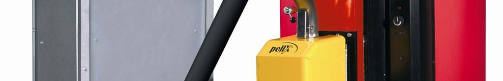
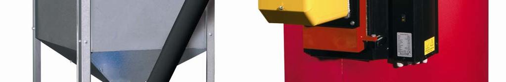
16 Safety Instructions 1.11 Delivery Check List The standard delivery includes the above shown equipment. The pellet burner parts list is shown on the next page. The sealing cords, 2 pieces, and the stop screw, 1 piece, belong to the mounting flange. The following items are also included in the box: Instruction Manual Short Maintenance Instruction (A4 Poster) Plastic Tubing (Grey Pellets Tubing) Hose Adapter Between the Plastic Tubing and the Flame Trap Pipe Hose Clamps, Two (2) Pieces (For the Plastic Tubing) Suspender (Straps for the Feed Screw) Signal Cable, 118 / cm (15-Poles D-Sub Cable) Main Power Cable, / cm (For the Main Power Supply to the Burner) Temperature Sensor Cable, / cm, Temperature Sensor Start / Stop, For Connection to the Control Box. ( / cm Length As Option) 118 / cm Device Cable Control Box Burner 59 / cm Compressed Air Hose Control Box Burner 16
17 Safety Instructions 1.12 Burner Parts List B Stop Plate B Mantle B Feed Trap Pipe / Flame Trap Pipe B Mounting Bracket, Ignition Element B Mounting Bracket, Casing B Mounting Flange B Sealing Cord Ø10,2st B Sealing Cord 8x3 B Casing B Overheat Protection 95 C B Overheat Protection Cover B Holder, Flame Sensor B Combustion Chamber Tube B Mounting Bracket, Ignition Unit B Clean Blow Pipe B Insert Joint B Cut Coil Joint B Burner Body B Triac Unit B Flame Sensor B Fan B Ignition Element 17
18 Precautions 2. Precautions Before selling a PellX burner, the authorized dealer or distributor must verify that all conditions necessary for creating a functional installation are fulfilled. If extra modifications have to be carried out, information must be provided before selling the burner. This section describes in general the precautions for an approved installation. The installation shall be done by a certified and qualified PellX contractor or in cooperation with an authorized PellX installation contractor. For new or changed installations, verify that the work is done in accordance to local codes and regulations. Electrical authorization is required for the electrical installation. The final installation shall be inspected and tested during operation by the authorized PellX contractor. We recommend you to contact a chimney sweeper about the installation plans. WARNING It is absolutely forbidden to connect the burner directly to a wall socket. PellX requires that the burner s power supply must be controlled by a high limit (temp) manual reset device like the Honeywell L4006H1004 and a low water cut off (LWCO) device like the Taco LWCO LF. Never remove the burner from the boiler combustion chamber without disconnecting the 120 V main power supply. The door and the mounting flange must be isolated to avoid the risk of burn injuries. The installation of the pellet auger must be performed in accordance with these instructions to eliminate any risk of injuries caused by crushing or being caught in the auger. The manual flue damper, if any, must be fully open. All doors and flue gas pipe connections to the combustion chamber must be tight. There must be an open inlet valve to the boiler room. The free area of the valve should correspond to the chimney cross sectional area. 2.1 Boiler It is important to check that the combustion chamber in the boiler is big enough to ensure that the flame does not come in contact with the water-cooled walls. Verify that the boiler s capacity range complies with the burner. There must be enough space for the ash to accumulate. The exhaust gas channels should not be so narrow that they can easily be clogged with ash. The boiler combustion chamber must comply with the dimensions shown in section 1.8 Dimensions. The distance between the front edge of the burner and the rear part of the combustion chamber should be at least 12 / cm, which can be adjusted with the supplied mounting flange (max. 2-3/4 / 7 cm). The minimum distance to the bottom of the fireplace depends on the boiler design. There must be 18
19 Precautions enough space for the quantity of ash build up that is created during at least one week s use in the winter heating season. 2.2 Chimney We recommend that you have a local chimney sweeper or other corresponding authority make an inspection and provide advice and instructions on the chimney measurements in accordance with local codes and regulations. This must be considered before installing and operating the burner: A suitable chimney diameter is between approximately 4 to 6 / 10 to 13 cm for a factory made steel chimney or steel insert in a brick made chimney lined in accordance to local codes. The chimney should then be of a length that gives a draught of 0.06 to 0.08 of water (39 F) / to cm of water (4 C) or Pa when in operation. Measures have to be taken if the chimney is smaller or much larger in diameter in order to give the proper draught and flow. The pressure drop in the boiler also has an effect on the required draught. A draught restrictor must be mounted to maintain a correct and stabile chimney draught. Always check the exhaust gas temperature. Directly after the boiler it should be 356 F to 482 F / 180 C to 250 C. Too high a temperature can damage the chimney and is not economical. Too low a temperature, a very high chimney, or a large chimney diameter creates a risk for condensation that can cause corrosion and damage due to freezing. Measured three feet (one meter) down from the top of the chimney, the temperature of the exhaust gas should be at least 176 F / 80 C. This temperature should be taken when the burner has almost reached the stop temperature. If the temperature is below 176 F / 80 C, it is suggested that you mount an insert tube or add insulation to the flue pipe. This will raise the temperature without influencing the efficiency. You can also increase the burner effect or remove baffles in the boiler. In both cases the efficiency is reduced. The draught restrictor can be of some use against condensation, but it cannot typically compensate for large temperature variances. 19

 (not included). Make sure that the stop screw on the flange is easily accessible. Mount the burner in the mounting flange.")
20 Pellet Brner, Hopper and Auger Installations 3. Pellet Burner, Hopper and Auger Installations 3.1 Burner Installation Decide where the burner is to be mounted in the boiler. Consider the lateral position of the door. You should be able to open the door with the burner mounted. You may need to reverse the door hinges in order to open it with the mounted burner. Drill holes for the mounting flange in the door. Put a layer of insulation cement or high temperature silicone on the flange s sealing surfaces towards the door. Mount the flange with steel 8.8 screws and nuts (5/16 / 8 mm) (not included). Make sure that the stop screw on the flange is easily accessible. Mount the burner in the mounting flange. Position the burner to ensure that the mantle cone passes the inner sealing cord. Fix the burner with the stop screw. Do not tighten the screw too hard as the mantle can be deformed or the screw can be broken. 20
 with holes for the flange stop screw is a practical complement. Insert the stop plate in the combustion tube and mount the burner casing.")

21 Pellet Brner, Hopper and Auger Installations Insulate the flange and the mantle with mineral wool. An extra covering plate (not included) with holes for the flange stop screw is a practical complement. Insert the stop plate in the combustion tube and mount the burner casing. The photographs below are of the Pivot Arm Kit KMP PX21 from Ariterm Sweden AB. More information can be found on the Ariterm web site, Check that all doors and valves are tight to avoid any unintentional air infiltration. The manual damper, if any, must be fully open. This is especially important if the chimney is narrow or generates bad draught for any other reason. Otherwise, there may be a risk of smoke leakage during the combustion start sequence, especially if the burner is not yet correctly adjusted 3.2 Pellet Hopper Installation The pellet hopper should be designed to avoid as little dust as possible in the boiler room when replenished. The hopper should be built with and covered by a non-combustible material like sheet metal or gypsum boards. You should be able to remove the auger for cleaning without emptying the hopper. Wood pellets should be stored in a dry environment. Pellets that have been damaged by damp conditions will cause feeding and combustion disturbances. Your PellX dealer can offer several storage alternatives from 180 lb / 300 litre mini-hoppers to large multi ton storage hoppers for truck replenishment. WARNING Dust from combustible material can cause an explosion! Hoppers replenished by injection from a bulk truck must be evacuated by an outdoor discharging filter. The hopper must not be built of material that can create static electricity discharge. 21
. Adjust by loosening the clamp (2) and move the plastic tube to the right distance.")
22 Pellet Brner, Hopper and Auger Installations 3.3 Pellet Auger Installation Auger Diameters of 3 / 7.62 cm, 3-1/4 / 8.25 cm, or 6-5/8 / cm, mounted in MAFA Micro, Mini or Midi hoppers. Check that the spiral lays 9/16-1 / 1.43 cm cm from the end of the plastic tube (1). Adjust by loosening the clamp (2) and move the plastic tube to the right distance. Locate the hopper so that the auger is correctly placed against the burner with an inclination between 30 and 45 degrees of angle. Put a suitable hook or loop in the roof above the fixing hole of the feeder. Insert the feeder into the hopper outlet tube. It should rest on the hopper lid (3). Secure the lid with two short screws (4) or use a clamp (5) as a stop. Hang the feeder in the hook with the suspender. Mount the blue pellet tube and make the final adjustment against the burner. Adjust the position of the hopper and auger so that the hose adapter can be pressed into the flame trap pipe. The tube must have an unbroken slope without being stretched or deformed. Check inside the hopper that the entire intake of the auger is visible. Adjust if necessary by loosening the clamp (2) and turning the plastic tube to the right position. Be sure to first mark the tube position lengthwise. Be sure to tighten the clamp before the auger is operated. Connect the main power supply cable to the socket on the burner. 22


23 Pellet Brner, Hopper and Auger Installations 23
24 Electrical Installation 4. Electrical Installation WARNING There is high voltage inside the equipment. All electrical installation and service work shall be done by certified and qualified personnel in accordance with local codes and regulations. Do not perform electrical work unless you have the required qualifications. Perform a complete burner shutdown and disconnect the power supply prior to performing any work on the burner. Observe all guidelines with respect to installation, service, and cleaning. 4.1 Installation of the Control Box The separate control box shall be mounted on a wall or a cool part of the boiler with a maximum allowed temperature of 104 F / 40 C. 1. When positioning for the control box, check that the cable to the temperature sensor reaches the insert on the boiler or the accumulator tank. Also check that the signal cable reaches the socket on the burner. 2. Remove the transparent cover from the control box. Mark the fixing points and fasten the box using at least two (diagonally positioned) of the four screw holes. If you place the box onto the boiler, be careful not to damage the boiler. The screws are not supplied. 3. Remove the front panel as shown below which is held by four screws. You have now access to the electronic circuit board and the control box terminal strip. The cables are run through the access ports on the bottom of the box and then are inserted into the proper holes on the bottom edge of the terminal strip and tightened with the terminal strip set screws. The connections to the control box terminal strip are as follows: 1, 2 Alarm relay (max. 1A, 24 V) 3, 4 Temperature sensor 1 5, 6 Temperature sensor For self cleaning 24

25 Electrical Installation Program Card Circuit Terminal Strip Connect the temperature sensor 1 to terminals 3 and 4. For accumulator control, connect the additional temperature sensor 2 to terminals 5 and 6. The cable to the temperature sensor must not be clamped or bundled together with the 120 V cables. 5. An external alarm device, a GSM alarm or a simple alarm lamp, can be connected to terminals 1 and 2. The outlet works as a relay and will not give a current. It is normally closed and opens at an alarm. The outlet must not be charged with more than 1A (at 24 V). A heavier load requires an external relay. 6. Reinstall the control box front panel and the transparent cover. 7. Connect the control box to the socket on the burner with the signal cable. The socket is positioned above the main power supply inlet on the burner and on the left bottom of the control box. Fasten the stop screws in both ends of the signal cable. Do not disconnect or connect the cable when the burner is being supplied 120 V. 25


26 Electrical Installation 4.2 Connection of Boiler Temperature Sensor The supplied sensor for the boiler temperature must be placed in an insert. Position the sensor so that it makes contact with the wall of the insert. Fix and insulate the sensor by using mineral wool or sealing rope. Clamp the sensor cable. Sensor Cable Boiler Insert Sensor Cable The sensor can also be fixed directly to the pressure tank plate on the hot water section of the boiler with 2-component epoxy glue. Let the glue cure and reinstall the insulation material of the boiler. An additional option is to fix the sensor with a clamp to the hot water supply. This is only if the temperature of the hot water supply always follows the boiler temperature. This can be an option at the accumulator control. Lightly tighten the clamp to prevent damage to the sensor. Insulate the hot water supply and the sensor with mineral wool. 26
27 Electrical Installation 4.3 Accumulator Tank Control The control box is wired for an accumulator tank control. The accumulator tank control increases the efficiency by getting longer operation time with less starts and stops. It is activated if both temperature sensor (1) and (2) are connected to the control box. Temperature sensor (1) starts the burner and is placed in the boiler. Temperature sensor (2) stops the burner and is placed at a low position in the tank. If the temperature at sensor (1) reaches 194 F / 90 C the burner stops regardless of the temperature at sensor (2). NOTE If the boiler is connected to the accumulator tank with direct water circulation, the start temperature of the burner should be set higher than 140 F / 60 C to prevent corrosion in the boiler. 4.4 Main Power Supply WARNING It is absolutely forbidden to connect the burner directly to a wall socket. Always check with your local authorities with jurisdiction (AWJ) concerning plumbing and heating code requirements for pellet burner installations. PellX requires that the burner s power supply must be controlled by a high limit (temp) manual reset device like the Honeywell L4006H1004 and a low water cut off (LWCO) device like the Taco LWCO LF. The main power supply cable is connected to the main power supply (120 V / 60 Hz) via the boiler s overheat protection and the safety switch on the door, if any. The connection is wired so that the overheat protection for the boiler and the burner switches off the phase wire (L). A separate overheat protection must be installed if not provided for the boiler. The wires in the supplied main power supply cable are marked as follows: Phase (L) Phase Earth (E) Phase Zero (N) This marking complies with the main power supply connection shown in the figure that follows. 27


28 Electrical Installation Control Box Connection 15 poles D-sub 4 A Slow Blow Fuse Main Power Supply 120 V Phase (L) Phase Earth (E) Phase Zero (N) Socket For Auger 120 V Old safety switches and overheat protections can cause malfunctions and should be replaced. The overheat protection sensor shall be placed in an insert or in the best position on the boiler for accurate temperature detection. Electrical cables and signal cables to the control box must not be in contact with any surfaces with a temperature above 158 F / 70 C. If the door is not provided with a safety switch, the main power supply cable must be installed so that the burner cannot be turned around or removed from the boiler without disconnecting the main power supply cable. It is suitable to fix the main power supply cable with clamps on the opening side of the combustion chamber door. NOTE The main power supply installation on the side of the burner must be easy accessible to allow easy disconnection of the voltage when carrying out cleaning and maintenance. Control Box Connection Fuse Holder Shown Extracted with Fuse Socket for Auger 120 V Main Power Supply 120 V 28
29 Electrical Installation 4.5 Wiring Diagram A separate large print Control Panel Adjustments Instruction Sheet shows this electrical drawing on page 4. 29
30 Start / Test / Adjustment 5. First Start / Test Functions / Adjustment during Operation The burner is not factory adjusted. A preliminary adjustment must be carried out before its first start. The adjustments are simplified if the built in test functions are used, after which you can start the burner and do the fine adjustments in operation with a flue gas analysis instrument, not included. The fine adjustments should be repeated after some weeks in operation and when the following has occurred; lbs / kg of pellets has been used. The pellet feed is stabilized. The combustion chamber tube is burnt in and any layers of tar in the boiler have disappeared. 5.1 Test Functions of the Burner / Preliminary Adjustment First Start To start a test function, turn off the power switch and set the operation switch to the desired test function (4-9). If the burner is in operation when the power switch is turned off, the burner has to shut down. Turn the burner power switch on. The green Operating Switch ON lamp flashes when the power switch is turned on. The desired test function set by the operation switch starts when the test button is pushed. The red Alarm / Test lamp is illuminated as long as the test is going on. NOTE Note that adjustments will change when you adjust the potentiometers even if you aren t in a test function mode. To stop the test functions and return to the operation mode turn off the power switch and set the operation switch to the desired operation function (0-3). When the power switch is turned on again, the burner will be in the desired operation and will start as soon as the boiler temperature is below the start temperature. Refer to the Control Panel Adjustments Instruction Sheet which accompanies the PellX manuals for a graphical display on how to conduct each function test Function 9: To Load Pellet Auger Disconnect the hose from the auger and hang a bucket under the auger discharge to catch the pellets. Alternatively, disconnect the hose from the flame trap tube on the burner and put the end of the hose into a bucket to catch the pellets. When filling the auger, never allow the pellets to be feeding the burner. Follow the instructions in section 5.1, setting the operation switch to # 9. Now push the test button once and wait 5 seconds. The Test LED is solid red and the Operating LED flashes green. Push the test button twice. The Test LED flashes red and the Operating LED flashes green. The auger motor feeds for 15 minutes. Once completed, the Test LED is off and the Operating LED flashes green. Repeat the whole procedure if needed until the auger screw is full of pellets. 30
31 Start / Test / Adjustment Function 9: Start Up Pellet Amount The pellet auger screw must be filled with pellets prior to running this test. Lift the pellet hose from the flame trap pipe and place a bucket under the hose. Follow the instructions in section 5.1, setting the operation switch to # 9. Start the test function by pushing the test button twice. The Test LED is on as solid red and the Operating LED flashes green. The LED bar displays the start up pellet amount. The screw feeds a continuous start up amount of pellets. The LED display shows the set start up level (1-10) segments illuminated. The start up pellet amount can be adjusted when you adjust the # 9 Start Up Pellet Amount potentiometer. When the test is finished, the Alarm / Test light turns off. (If the test button is pushed again another start portion will be executed.) Weigh or measure the collected portion of pellets. We recommend approximately 1 cup / grams / 7-8 oz. The amount of pellets should cover the ignition hole at the gable of the combustion tube. If the start portion is too small, the pellets may extinguish before the flame sensor has recognized the flame. When the burner switches to its operation level, an alarm will occur and the burner will stop operating. Avoid pellet portions above 1-1/2 cups / 12 oz. due to risk of boiler pops Function 8: Test and Adjust Pellet Feed Rate Lift the pellet hose from the flame trap tube and place a bucket under the hose. Follow the instructions in section 5.1, setting the operation switch to # 8. Start the test function by pushing the test button once. The Test LED is on as solid red and the Operating LED flashes green. NOTE When the test button is pressed once, the auger runs with 20 second pauses for 18 cycles. If the test button is pushed twice, the auger runs with only 2 second pauses for 18 cycles, reducing the total time of the test. The screw will feed several small doses of pellets during a period of 6 minutes in the same way as it does under operation. The display shows the set feed rate level (1-10 segments). When the test is finished in 6 minutes, the Alarm / Test light turns off. (If the test button is pushed again another operation portion will be done.) Weigh or measure the collected portion of pellets. 31
32 Start / Test / Adjustment Operation feed based on pellets with energy content 4.8 [kwh/kg]. Test portion [gram] Supplied Effect [Btu / Hour] Supplied Effect [kw] ,652 (12.5) , , , , , , , ,500 (40) Supplied Effect [Btu / Hour] Supplied Effect [kw] 160, , , , , , , Test Portion Grams / 6 Minutes Test Portion Grams / 6 Minutes Which supplied effect to choose depends on the type of boiler the burner is mounted in and the power demand. NOTE The pellet feed rate operation can be adjusted while the burner is in full operation mode without having to change the operation switch. When you adjust the # 8 Operation Pellet Amount potentiometer, wait a couple of minutes and then recheck the flame quality and combustion gasses. NOTE The operation portion should be checked a couple of times per year and always in conjunction with any change of pellet quality. If the deviation is more than 0.5 kg / hour (test portion deviates more than 50 grams / 6 minutes) from the instructions in the Warranty and Installation Certificate, the operation portion should be adjusted. 32
33 Start / Test / Adjustment Function 7: High Effect Fan Speed Adjustment Follow the instructions in section 5.1, setting the operation switch to # 7. Start the test function by pushing the test button once. The Test LED is on as solid red and the Operating LED flashes green. The fan runs at the adjusted high effect level. The display shows the set level (1-10 segments). The high effect fan speed can be adjusted using the # 7 High Effect Fan Speed potentiometer. The test runs for 6 minutes or until the operating switch is turned off. Up to 68,243 BTU / 20 kw, supplied on high effect level, we suggest a base starting adjustment of 5 illuminated segments in the display. At higher effect levels (more pellets), more fan speed will be required (10 segments in the display). NOTE The high effect fan speed can be adjusted while the burner is in full operation mode without having to change the operation switch. When you adjust the # 7 High Effect Fan Speed potentiometer, wait a couple of minutes and then recheck the flame quality and combustion gasses Function 6: Maximum Run Time This function controls the maximum run time of the burner while in high effect. By limiting the run time you can automatically stop the burner and force it into a controlled shut down and self cleaning cycle, followed by a start cycle. Very poor quality pellets might limit you to only one hour of burning where as top quality pellets can be burned all day without the need for cleaning. Follow the instructions in section 5.1, setting the operation switch to # 6. Start the test function by pushing the test button once. The Test LED is on as solid red and the Operating LED flashes green. Push the test button once. The LED bars display the maximum run time with each LED bar equal to 30 minutes. The maximum run time can be adjusted using the # 6 Max Run Time potentiometer. If you have poor quality pellets and long run times, clinkers or sinter can form. Reducing the run time forces the burner to shut down and go through a cleaning cycle. The burner will re-ignite and continue operation. Adjustable max time Lights displayed: None Operating time - 1 hour. 1 Operating time - 2 hours. 2 Operating time - 3 hours. 3 Operating time - 4 hours. 4 Operating time - 5 hours. 5 Operating time - 6 hours. 6 Operating time - 7 hours. 7 Operating time - 8 hours. 8 Operating time - 9 hours. 9 Operating time - 10 hours. 10 Operating time - 11 hours. 33
34 Start / Test / Adjustment Function 5: Display The Boiler s Turn Off Temperature And Current Temperature Follow the instructions in section 5.1, setting the operation switch to # 5. Start the test function by pushing the test button once. The Test LED is on as solid red and the Operating LED flashes green. The turn off (stop) temperature of the burner is shown (preset value of temperature in the boiler). The display shows the set level (2-10 segments). The stop temperature (maximum temperature) can be adjusted using the # 5 Boiler Temp potentiometer. The stop temperature can be adjusted between F / C, 2-10 segments in the display. Below 113 F / 45 C the display is out and at 194 F / 90 C the display is completely illuminated. The resolution on the display is 41 F / 5º C per segment. For example, if 3 segments are on, the temperature is at least 40 + (3x5) = 55º C and max. 59º C When test button is pushed a second time (within 6 minutes) the actual temperature of temperature sensor 1 is showed. The display indicates actual temperature (0-10 illuminated segments). When test is pushed a third time (within 6 minutes) the actual temperature of temperature sensor 2 is showed. This is only if the accumulator tank control is active. If sensor 2 is not mounted, then all the display segments are off. The display indicates actual temperature (0-10 segments). When the test button is pushed a fourth time (within 6 minutes) you will leave the test function. If you push test button again you will restart the test. The test will run for 6 minutes or until the power switch is turned of. Indication Boiler Temperature Indication Boiler Temperature Temp F Temp C Segments in Display Segments in Display Function 4: Function Test - Burner This function allows a qualified technician to verify that all the major components are working. This test is typically performed with the burner housing removed from the burner's combustion chamber. The pellet hose needs to be disconnected and placed into a bucket to collect the pellets that will come out during this test. Extra care needs to be taken as live electrical wires, the heating element, and the fan blades will be exposed. Follow the instructions in section 5.1, setting the operation switch to # 4. Start the test function by pushing the test button once. The Test LED is on as solid red and the Operating LED flashes green. 34
35 Start / Test / Adjustment The ignition element and fan runs for a maximum of 5 minutes. (The fan runs in order not to overheat the ignition element.) When you introduce light to the flame sensor using a flashlight or lamp, the ignition element and fan will turn off. The flame sensor measures the intensity of the light and the LED displays the light intensity on the display (0-10 segments). If the test button is pushed now, the fan and screw motor will run in high effect level for a maximum of 6 minutes. NOTE The screw motor runs intermittently, not all the time. The test is run for 6 minutes or until the power switch is turned off Function 4: Function Test - Control Box Any time during the burner function test (4) above, you can double click the test button and the test will switch over to test the control box. The Test LED is off and the Operating LED flashes green. The magnet valve 1 and 2 will open and close twice each, creating four audible clicking sounds. Close the test function by turning the burner power switch off after the cycling of the valves. 5.2 First Start / Adjustment during Operation When carrying out a preliminary adjustment and control of the functions, the combustion quality can be evaluated by a visual inspection of the flame size and color. Adjust the air first. Alter the operation feed only if it shows that the effect is too high (operation time below 15 minutes, high flue gas temperature, narrow boiler) or low (too long operation time, too low flue gas temperature). When the combustion is stable (approximately 15 minutes after the start) the flame should have a light orange to light yellow nuance. It is normal that the color varies a bit. If the flame is red and wide it means that the burner is not getting sufficient air. A white and short flame means that the burner is getting too much air. It will take some time before the change appears. Adjust little by little and wait about two minutes before the next check. If you cannot see the flame without opening the door you can still get an indication of how the flame looks at the moment you open the door. Tune the stop temperature and supervise the burner during the next firing cycle. White smoke mainly consists of water vapour and is normal at low outside temperatures. Grey or black smoke from the chimney is an indication of insufficient air. If the boiler was previously wood fired, the smoke may be dark and have a strong smell caused by tar that is burnt away from the walls in the boiler and the chimney. This smell may last for about a week. The fine adjustments should be done first when the installation has been in operation for one or two weeks and at least 441 lbs / 200 kg pellets have been consumed. The burner must have been in operation in high effect for at least 15 minutes and the boiler temperature should be at least 140 o F / 60 o C before the adjustment starts. Use a flue gas instrument. The recommended CO2 content is a mean value between 9 12% on high effect. The CO mean value should be under 300 ppm. Consider that even if you can adjust the burner with a low CO value, at higher CO2 values there should be a margin to manage the normal variations that are caused by pellet quality, draught condition and ash 35
 while the burner is in operation as noted in the table below.")
36 Start / Test / Adjustment content in the combustion tube. It is possible to check the set values on the LED display for each of the functions (5-9) while the burner is in operation as noted in the table below. Press and hold the test button while rotating the Operation switch through each of the desired test functions. In functions 6, 7, 8 and 9 the set values for the maximum run time (6), the high effect fan speed (7), the operation pellet feed rate (8), and the start up pellet amount (9) settings are shown on the LED. In function 5, the actual temperature for temp sensor 1 is shown (0-10 segments = o F / o C). The set stop temperature is not showed in operation. Always return the operation switch to operation level 0, 1, 2, or 3 after this check of the set values. Test Function, Burner Standby 0 Operation dt 50 F / 10 o C 5 Boiler stop temperature and current temperature settings Test Function, Burner In Operation 0 Operation dt 50 F / 10 o C 5 Shows actual boiler temp - temp sensor 1 1 Operation dt 60 F / 15 o C 6 Max run time setting 1 Operation dt 60 F / 15 o C 6 Shows max run time setting 2 Operation dt 70 F / 20 o C 7 High effect fan speed setting 2 Operation dt 70 F / 20 o C 7 Shows high effect fan speed setting 3 Operation dt 80 F / 25 o C 8 Operation pellet amount setting 3 Operation dt 80 F / 25 o C 8 Shows operation pellet amount setting 4 Self Cleaning Test and Function Test 9 Start up pellet amount setting and 15 minute auger fill mode 4 None 9 Shows start up pellet amount setting 36
37 Trouble Shooting 6. Trouble Shooting WARNING If the ignition fails, do not open the fireplace door until the combustion chamber is totally ventilated! Wait at least 10 minutes after the third starting attempt. Wear protective clothing and eye protection as the door may be hot. Open the door slowly to prevent hot pellets or particles from flying out the door. Always disconnect the main power supply before working on the burner. NOTE The Alarm / Test light is confirmed (switched off) by turning off the power switch on the control box for a few seconds. Turn on the power switch. The control box is activated and the Alarm / Test light is now off. LED Indication Possible Problem Possible Solution - Contact your Contractor or Perform the Following Steps Failed to Start Pellets not getting to the burner. Incorrect start portion. Broken or misaligned ignition element. Check pellet supply. Check for pellets hanging in pellet supply breaker. Check for clogs in screw auger. Check start portion, approximately 1-1/4 to 1-1/2 cups. Too much will cause boiler pops - wood gas explosion! Check ignition element with test function 4. (Section 5.1.7) Disconnect feed screw and remove burner. Heating element should glow for about 2 minutes. A resistance check of the ignition element should be around Ohms. Check to see if the ignition element s position is adjusted to be right up against the back of the combustion chamber. (Section 7.2) 37
38 Trouble Shooting LED Indication Possible Problem Possible Solution - Contact your Contractor or Perform the Following Steps Check pellet supply for clogs or bubble. Failed to run in Extra Safe Mode Check start portion of pellets. (Section 5.1.2) LED Indication Possible Problem Possible Solution - Contact your Contractor or Perform the Following Steps Triac temperature has exceeded 158 F (70 C) stopping the pellet feed temporarily. Boiler is dirty, causing excessive back pressure. Clean the boiler. The maximum output is set too high. Reduce the output. (Section 5.1.6) Too much draft. Check the draft. Extra Safe Mode * Interruption in the pellet feeding. Flame sensor dirty or faulty. Check pellet supply for clogs or bubble. Pellet screw auger angle too steep. (Section 3.3) Replace the flame sensor. (Section 7.4) Check flame sensor value. (Section 5.1.6) * Extra Safe Mode = Burner is forced to run at a reduced output (65%) because the flame sensor has lost signal during operation. 38
39 Trouble Shooting LED Indication Possible Problem Possible Solution - Contact your Contractor or Perform the Following Steps No Power Switch is Off Flame trap overheat protection tripped. High temperature limit switch tripped. LWCO tripped. Loose power or control plug. Fuse blown on burner. House breaker box breaker tripped. Turn Switch On Boiler is dirty, causing excessive back pressure. Clean boiler and Reset the Overheat Protection on the Flame Trap Pipe. (Section 7.1) Burner combustion chamber is clogged. Clean burner. Turn up air pressure on self cleaning. Decrease max run time between cleaning cycles. (Section 5.1.5) Check pellet quality. Reset the Overheat Protection on the Flame Trap Pipe. (Section 7.1) Maximum output set too high. Reduce output. (Section 5.1.3) Reset the Overheat Protection on the Flame Trap Pipe. (Section 7.1) Incorrect draft. Check draft. Reset the Overheat Protection on the Flame Trap Pipe. (Section 7.1) Check preset boiler temperature setting on PellX controller. Reset high limit switch. Do not set high limit above 212 F (100 C). Water level in boiler low. Determine cause. Fix the problem. Check plug and cords. Check fuse. Determine cause. Replace fuse. (Section 1.5) Check breaker. Determine cause. Replace breaker. 39
40 Trouble Shooting LED Indication Possible Problem Possible Solution - Contact your Contractor or Perform the Following Steps Test Mode (4-9) Nothing is wrong. The operation switch is in test level (4-9). If the test button is pushed, the red light is also illuminated and the test function starts. Put the operation switch in any of the operation levels (0-3). Turn the power switch off and then back on. LED Indication Possible Problem Possible Solution - Contact your Contractor or Perform the Following Steps An interruption in the pellet feed. Check the pellet supply for clogs or a bubble. Tap the hose for pellets that may be hung up in the hose. Does Not Start Start amount is too small. Check the start amount and adjust as needed. Out of pellets. Add pellets, refill the auger, and restart the burner. 40
41 Trouble Shooting 6.1 Trouble Shooting Self Cleaning Problem Possible reason Possible Solution - Contact your Contractor or Perform the Following Steps 1. The combustion chamber tube is packed up with ashes much earlier than expected. 1. The Compressor has insufficient air pressure or is switched off. 1. Adjust the pressure upwards on the compressor. Investigate why the compressor is switching off. The recommended pressure is PSI / 6-8 BAR. 2. The ignition element is not in contact with the combustion chamber tube. 3. One of the solenoid valves is stuck in the closed position. 4. Bad pellet quality which sinters easily. 2. Adjust according to the instructions from your local contractor. 3. Check the function in test function 4, Self Cleaning Valve Test. If it doesn t work in spite of the fact that it gets tension, replace the whole unit. Don t try to repair the solenoid valve. 4. We recommend using pellets with a minimum ash melting temperature of 1300º C. 2. The compressed air cleaning works continuously. The two solenoid valves are stuck in the open position. Check the function in test function # 4, Self Cleaning Valve Test. 41


42 Repair 7. Repair 7.1 Resetting the Overheat Protection on the Flame Trap Pipe. The overheat protection on the flame trap pipe is activated at 203 F / 95 C. The most common reason for overheat protection activation is when ash is not removed from the burner, causing the combustion to take place at a higher level in the combustion chamber tube. The overheat protection may also activate when a power interruption occurs during operation, which will raise the temperature during the phase-out mode as the combustion fan has no power to operate. WARNING Disconnect the main power supply by removing the cable from the burner before the overheat casing is removed; otherwise, there is a risk of being in contact with live current. Dismantle the overheat protection casing using a 3 mm Allen key. Press the reset button on the overheat protection. Remount the overheat protection casing and reconnect connect the main power supply cable to the burner. If the overheat protection activates in spite of ash removal once a week, the reason might be bad quality fuel (high ash content or easy sintering ash). Long operation periods of low combustion fan speed might also be a reason. This will raise the temperature, directly because most of the combustion will take place inside the combustion chamber tube and indirectly because the ash does not blow out of the combustion chamber tube in a normal way. Contact an authorized PellX installation contractor or distributor if the problem remains. Overheat Protection Cover Overheat Protection Switch - Push to Reset 42


43 Repair 7.2 Replacement of the Ignition Element 1. Remove the connecting cable to the burner s main power supply, the electrical cable to the pellet auger, and the control box cable. Remove the pellet auger tube from the flame trap pipe. 2. Remove the casing of the burner. Loosen the two upper nuts and remove the rear nut. Pull the casing backwards to remove it. Casing Upper Nuts - One Each Side Remove the Casing Casing Rear Nut 3. Open the two toggle fasteners, which position the burner body against the mantle s end plate. Angle the burner body and pull it inclined upwards / backwards so that the flame trap pipe releases from the combustion chamber tube. Open the Toggle Fasteners on Each Side Pull the Burner Body Upwards / Backwards 43
 by loosening the set screws and pulling the cables straight out.")

44 Repair 4. Remove the cables of the ignition element on the Triac unit s terminal strip (no. 9 and 10 as shown in the figure below) by loosening the set screws and pulling the cables straight out. Remove the ignition element from the burner body (Allen key 2.5 mm, on the bottom of the burner). Remove the clamp and pull the element out of its tube , 10 Triac Unit Terminal Ignition Unit Element 44
 shall be placed 1/32-1/16 / 1-2 mm outside the plate. Take care that the tube remains in its notch in the plate bracket.")

45 Repair Mounting Screws for the Ignition Unit Mounting Screws for the Ignition Wires 5. Push the new ignition element into the tube. The insulation (porcelain) shall be placed 1/32-1/16 / 1-2 mm outside the plate. Take care that the tube remains in its notch in the plate bracket. The sheet plate shall be inside the tube and the tube moved back until it reaches the bottom. Mount the clamp and tighten the cover screws with moderate force, just not enabling the element to be moved forwards and backwards. 6. Mount the ignition unit into the burner body. Lead the cables through the cable bushing in the fan bracket, pulling them through as far as possible, making sure the cables do not interfere with the rotation of the fan. Connect the cables to the Triac unit s terminal strip and tighten the set screws. Secure the two cables together with a strap. Remount in reverse order. The ignition element is secured on the underside of the burner body only after the burner body is assembled with the mantle and combustion chamber tube. Fix the ignition element by slightly pushing it against the combustion chamber tube and then tightening the screws. Check that the tube is centered and opposite the ignition hole of the combustion chamber tube. 45


46 Repair 7.3 Replacement of the Combustion Air Fan 1. Remove the ignition unit according to the instructions in section 7.2 Replacement of the Ignition Element. Keep the ignition element in the ignition unit. Note the wiring and connection of all cables. 2. Remove all straps from the mounting bracket. Mark the position of the mounting bracket on the burner body. Unscrew the 4 screws (Allen key 2.5 mm) and remove the bracket. Disconnect the electrical cables from the Triac unit s terminal strip by loosening the set screws and pulling out the connectors. Unscrew the 4 screws and remove the fan. Mount the new fan. Check that the cable bushing for the ignition element cable is fitted. 3. Remount the ignition element according to the instructions in section 7.2 Replacement of the Ignition Element. Put the bracket back to the marks done in step 2 above. Fix the cables for the ignition element, the overheat protection switch, and the flame sensor to the bracket with straps. Make sure that the fan rotates freely without any interference from any cables. 4. Adjust the bracket position if the burner casing does not easily fit the rear mounting screw. Replacement of the combustion air fan requires a new tuning of the burner by an authorized PellX installation contractor. Strap Bracket Cable Clamp Cables Bracket Strap 46


47 Repair 7.4 Replacement of the Flame Sensor 1. Disconnect the main power supply cable, the electrical cables to the pellet auger, and the control box cable. Remove the burner casing. Unscrew the two upper nuts and remove the rear nut. Pull the casing backwards. 2. Note the flame sensor position and the cable wiring on the flame sensor terminal strip. Remove the cable straps on the bracket. Disconnect the terminal strip cables by loosening the set screws and by pulling the cables straight backwards. Unscrew the outer nut of the flame sensor fastener and pull the flame sensor with nut and bushing out of the fastener. 3. Move the nut and bushing to the new flame sensor. The bushing should be pushed all the way back to the shrink tube (the black cover). Mount the flame sensor in the fastener. The nut is tightened with moderate force by hand, just not enabling the sensor to be moved. 4. Connect the cables to the flame sensor terminal strip, tightening the set screws. Fix the cable to the bracket with straps. Remount the casing and connect the cables. NOTE The flame sensor has a blue and white cable that must be connected as shown in the figure below. Flame Sensor White & Blue Flame Sensor Terminal Flame Sensor with Fastener Flame Sensor White & Blue 47

48 Repair 7.5 Replacement of the Triac Unit 1. Disconnect the main power supply cable, the electrical cable to the pellet auger, and the control box cable. Remove the pellet tubing from the flame trap pipe. 2. Remove the burner casing. Unscrew the two upper nuts and remove the rear nut. Pull the casing backwards. Open the toggle fasteners, which keep the burner body against the end of the mantle tube. Angle the burner body and pull it inclined upwards / backwards to release the flame trap pipe from the burner body. Place the burner body with the Triac unit facing upwards on a steady and robust working area. 3. Remove the electrical connections by loosening the set screws and pulling the cables straight out from the terminal strip. Unscrew the 4 screws (Allen key 2.5 mm) which keep the Triac unit against the burner body. Take care of the screw stand off hardware, which are fitted between the burner body and the Triac unit. 4. Fit the new Triac unit and remount in reverse order. Remount the screws with the stand off hardware in the same positions. The Triac unit will overheat without the stand off hardware. Screws & Stand Off Hardware - 2 per side Terminal Triac Unit 48

49 Repair 7.6 Replacement of the Program Circuit Card 1. Pull out the main power supply cable to disconnect the voltage to the burner. Open the control box and remove the front panel. Get ahold of the edges of the circuit card and pull it straight out. 2. Fit the new circuit card with the contacts on the correct side, carefully press it straight in. 3. Remount the other components in reverse order. 16 Bit Processor Chip NOTE After a replacement of the program circuit card the burner sometimes has to be readjusted. This depends on between which program versions the change is done. Consult an authorized PellX contractor. 49
Operating Instructions Manual PellX 20 & 35 kw Pellet Burner with External Auger
 Operating Instructions Manual PellX 20 & 35 kw Pellet Burner with External Auger SAVE THESE INSTRUCTIONS This manual is for the Home Owner. Important operating and maintenance instructions are included.
PLEASE KEEP THESE INSTRUCTIONS FOR FUTURE REFERENCE PELLET STOVE HP-0020S
 PLEASE KEEP THESE INSTRUCTIONS FOR FUTURE REFERENCE PELLET STOVE HP-0020S Freestanding OWNER S MANUAL Contact your building or fire officials about restrictions and installation inspection requirements
Operating Instructions Manual Janfire NH/Integral Pellets Burner with External Auger
 Operating Instructions Manual Janfire NH/Integral Pellets Burner with External Auger 11899008 R1 EN Janfire 2008 Due to constant development, Janfire AB reserves the right to change part or parts of this
Maintenance 50 Serie CAUTION. Before resetting your electronic card that displays an error code. OVERHEAT MESSAGE
 29-10-2013 CAUTION Before resetting your electronic card that displays an error code. OVERHEAT MESSAGE Service the stove COMPLETELY as described in this manual. Check the chimney pipe. BLOCKED FLUE MESSAGE
Corn Flame Energy Corn Stove Model 3000
 Corn Flame Energy Corn Stove Model 3000 Installation and Operation Guide Read thoroughly before starting installation Save this manual for future reference SAFETY NOTICE If this stove is not properly installed,
PELLET BURNER PV 350
 PELLET BURNER PV 350 INSTRUCTION MANUAL v1.1 1 PRODUCT DESCRIPTION...3 2 SAFETY RULES...3 3 WARNINGS...4 4 INSTALLATION INSTRUCTIONS...5 4.1 BOILER REQUIREMENTS...5 4.2 PELLET CONTAINER...6 4.3 INSTALLATION
Conversion Instructions Logano G234X. Gas boiler. Please read carefully before installing and servicing. Gas boiler
 Gas boiler UPON COMPLETION OF THE INSTALLATION THE INSTALLER MUST INSTRUCT THE OWNER AND OPERATOR ON THE FUNCTIONALITY AND THE PROPER OPERATION OF THE BOILER AND THE HEATING SYSTEM. INSTALLER MUST REVIEW
INTRODUCTION THIS MANUAL INCLUDES IMPORTANT SAFETY INFORMATION
 INSTALLATION AND OPERATING INSTRUCTIONS FOR THE HARDY Fuel Oil Furnace Models D-140 & D-350 HARDY MANUFACTURING COMPANY, INC. 12345 ROAD 505 PHILADELPHIA, MS 39350 PHONE: (601) 656-5866 FAX: (601) 656-4559
INSTALLATION, OPERATION AND MAINTENANCE. Ariterm Hybrid 20
 INSTALLATION, OPERATION AND MAINTENANCE Ariterm Hybrid 20 TABLE OF CONTENTS General...3 Installation... 4-5 Dimensions - with flue gas exhauster...6 Dimensions - without flue gas exhauster...7 Pipe installations...8
THELIN GNOME PELLET HEATER PLANNING & INSTALLATION GUIDE
 THELIN GNOME PELLET HEATER PLANNING & INSTALLATION GUIDE General Information Thelin Gnome Pellet Heaters are uniquely designed to provide a classic pot belly stove appearance while incorporating the latest
SERVICE AND INSTALLATION MANUAL MODELS HDO(H) OIL FOR YOUR SAFETY
 OIL FOR YOUR SAFETY") Bousquet Technologies Inc. 2121, Nobel, Ste Julie, Quebec, Canada, J3E1Z9 SERVICE AND INSTALLATION MANUAL MODELS HDO(H) OIL Oil-Fired air heater for industrial and commercial use. FOR YOUR SAFETY Do not
Bousquet Technologies Inc. 2121, Nobel, Ste Julie, Quebec, Canada, J3E1Z9 SERVICE AND INSTALLATION MANUAL MODELS HDO(H) OIL Oil-Fired air heater for industrial and commercial use. FOR YOUR SAFETY Do not
1. GENERAL SAFETY RULES
 ID180 & ID290 Indirect-Fired Diesel/Oil Construction Heaters Sure Flame Products Lethbridge, Alberta, Canada Telephone: (403)328-5353 Fax: (403)328-9956 www.sureflame.ca July 12, 2006 Service and Maintenance
INTRODUCTION TO HITZER STOVES INSTALLATION AND OPERATION
 INTRODUCTION TO HITZER STOVES INSTALLATION AND OPERATION Welcome to our proud team of HITZER heater owners. Your HITZER heater has the finest in Swiss craftsmanship and quality material to assure you that
JUMBO INDIRECT FIRED DIESEL HEATER OPERATING INSTRUCTIONS
 JUMBO INDIRECT FIRED DIESEL HEATER OPERATING INSTRUCTIONS Before using the heater, read and understand all instructions and follow them carefully. The manufacturer is not responsible for damages to goods
1. The structure and its description
 Thank you for using our KYUNG-DONG NAVIEN. To use this boiler in the proper way, be sure to read this manual fully before using it, and keep this manual with the warranty of the quality in a safe place.
SHERWOOD INDUSTRIES IS AN ENVIRONMENTALLY RESPONSIBLE COMPANY. THIS MANUAL IS PRINTED ON RECYCLED PAPER. OWNER S MANUAL
 SHERWOOD INDUSTRIES IS AN ENVIRONMENTALLY RESPONSIBLE COMPANY. THIS MANUAL IS PRINTED ON RECYCLED PAPER. PLEASE KEEP THESE INSTRUCTIONS FOR FUTURE REFERENCE PELLET STOVE Bern OWNER S MANUAL PLEASE READ
SWEBO Bioenergy Manual pellet burner PB50 Rev no. Date Page PBM1: (37) Installation and maintenance instructions
 Installation and maintenance instructions") PBM1:12 2008-10-16 1 (37) Installation and maintenance instructions PBM1:12 2008-10-16 2 (37) TABLE OF CONTENTS 1 GENERAL INFORMATION... 5 1.1 PELLET STORAGE... 6 1.2 CONSTRUCTION AND FUNCTION... 7 1.2.1
PBM1:12 2008-10-16 1 (37) Installation and maintenance instructions PBM1:12 2008-10-16 2 (37) TABLE OF CONTENTS 1 GENERAL INFORMATION... 5 1.1 PELLET STORAGE... 6 1.2 CONSTRUCTION AND FUNCTION... 7 1.2.1
INSTALLATION AND OPERATING INSTRUCTIONS. Ariterm 60+
 INSTALLATION AND OPERATING INSTRUCTIONS Ariterm 60+ CONTENTS General.... 2 Installation.... 4-5 Installation of temperature limit valve... 6 Measurements and connections... 7 Technical specifications and
INSTALLATION, OPERATION AND MAINTENANCE. ARITERM SWEDEN AB Installation, Operation & Maintenance /28
 INSTALLATION, OPERATION AND MAINTENANCE ARITERM SWEDEN AB Installation, Operation & Maintenance - 2009.02.18-1/28 CONTENTS IMPORTANT INFORMATION 4 4 5 Notification to building authority Inspection Sweeping
INSTALLATION, OPERATION AND MAINTENANCE. Ariterm Vedo
 INSTALLATION, OPERATION AND MAINTENANCE Ariterm Vedo CONTENTS General...3 Installation...4-5 Laddomat 21 Connection diagram...6 Temperature control valve...7 About burning wood...8 Operation...9-11 Service
Owner s Manual for. PennStoker
 Owner s Manual for PennStoker Table of Contents 1. Installation Placement ---------------------------------------------------------------------------------------- pg.3 Chimney Hook-up ---------------------------------------------------------------------------
CentroPelet ZV14 TECHNICAL INSTRUCTIONS HEATING TECHNIQUE. for regulation, use and maintenance of pellet stove
 HEATING TECHNIQUE Centrometal d.o.o. - Glavna 12, 40306 Macinec, Croatia, tel: +385 40 372 600, fax: +385 40 372 611 TECHNICAL INSTRUCTIONS for regulation, use and maintenance of pellet stove CentroPelet
OPERATING & MAINTENANCE MANUAL
 DO NOT DISCARD OPERATING & MAINTENANCE MANUAL Quality Fireplaces for Life INSTALLER: LEAVE THIS MANUAL WITH THE APPLIANCE Contact local building or fire officials about restrictions and installation inspection
Installation Electric Dryers Instructions 01
 Installation Electric Dryers Instructions 01 Questions? Call 800.GE.CARES (800.432.2737) or visit our Web site at: GEAppliances.com This is the safety alert symbol. This symbol alerts you to potential
Universal Fire Tube Boiler Wall Mount Models
 Universal Fire Tube Boiler Wall Mount Models USER S INFORMATION MANUAL Models WBRU**80W / 100W / 120W / 140W / 175W / 199W **NG denotes Natural Gas Model, LP Denotes Propane Model Heat Exchanger Bears
SHERWOOD INDUSTRIES IS AN ENVIRONMENTALLY RESPONSIBLE COMPANY. THIS MANUAL IS PRINTED ON RECYCLED PAPER.
 SHERWOOD INDUSTRIES IS AN ENVIRONMENTALLY RESPONSIBLE COMPANY. THIS MANUAL IS PRINTED ON RECYCLED PAPER. PLEASE KEEP THESE INSTRUCTIONS FOR FUTURE REFERENCE PELLET STOVE WINDSOR OWNER S MANUAL Contact
eurofire BIG 100, 200, 300 kw
 Datum 080603, rev 0 eurofire BIG 100, 200, 300 kw The Pellet Burner of the 21 st Century Ekosystem AB Björkevägen 84, S-805 97 GÄVLE, Sweden Table of Contents General Information 3 Read these instructions
Fig. 1 - Unit PGD4, PGS4, WPG4
 OWNER S MANUAL 14 SEER Single -Package Air Conditioner and Gas Furnace System with R -410A Refrigerant Single Phase 2 to 5 Nominal Tons Three Phase 3 to 5 Nominal Tons PGD4andPGS4SeriesE,WPG4SeriesB Fig.
Aqua Balance. User s Information Manual. WMB-155C Wall Mount Gas-Fired Combination Boiler Heating and Domestic Hot Water
 Aqua Balance WMB-155C Wall Mount Gas-Fired Combination Boiler Heating and Domestic Hot Water User s Information Manual * Low Lead Content If the information in this manual is not followed exactly, a fire
INSTALLATION AND OPERATING INSTRUCTIONS BIOCLASS HM
 INSTALLATION AND OPERATING INSTRUCTIONS BIOCLASS HM Thank you for choosing a DOMUSA TEKNIK heating boiler. Within the product range offered by DOMUSA TEKNIK you have chosen BioClass HM model. With a suitable
DH-Direct Fired Poultry Farm Diesel Heater
 DH-Direct Fired Poultry Farm Diesel Heater Comparison of Diesel Heater to Gas Heater Diesel LPG Gas LPG Gas KW 43 70 120 Fuel consumption/hr 3 5.1 8.8 Heat output 37000 60000 100000 Cost of fuel/lit or
Installation Instructions T 9822 Gas Dryer. en - US, CA. To prevent accidents
 Installation Instructions T 9822 Gas Dryer To prevent accidents en - US, CA and appliance damage read these instructions before installation or use. M.-Nr. 07 431 110 2 WARNING For your safety the information
USER S INFORMATION MANUAL
 USER S INFORMATION MANUAL HOT WATER HEATING BOILERS DOMESTIC WATER HEATERS 150,000-300,000 Btu/hr MODELS EB-EWU-02 IMPORTANT INSTALLER - AFFIX INSTALLATION MANUAL ADJACENT TO THE BOILER CONSUMER - RETAIN
KKKKKKKCOOKER HOOD INSTRUCTION MANUAL
 KKKKKKKCOOKER HOOD INSTRUCTION MANUAL Read this manual carefully before operation Pictures in this manual are for reference only, the product in kind prevail. E60MEW2M19 Contents 01 02 03 04 05 06 07 08
SAFE DRINKING WATER AND TOXIC ENFORCEMENT ACT
 Installation instructions for your new Spacemaker Laundry WSM2780 Gas Before you begin Read these instructions completely and carefully. IMPORTANT OBSERVE ALL GOVERNING CODES AND ORDINANCES. Note to Installer
User Manual. 110 Cup (55 Cup Raw) Gas Rice Cooker. Model: 177GRCLP, 177GRCNAT 12/2018. Please read and keep these instructions. Indoor use only.
 Gas Rice Cooker. Model: 177GRCLP, 177GRCNAT 12/2018. Please read and keep these instructions. Indoor use only.") 110 Cup (55 Cup Raw) Gas Rice Cooker Intertek 5010781 Conforms to ANSI STD Z83.11-2016 Model: 177GRCLP, 177GRCNAT 12/2018 FOR YOUR SAFETY Do not store or use gasoline or other flammable vapors or liquids
110 Cup (55 Cup Raw) Gas Rice Cooker Intertek 5010781 Conforms to ANSI STD Z83.11-2016 Model: 177GRCLP, 177GRCNAT 12/2018 FOR YOUR SAFETY Do not store or use gasoline or other flammable vapors or liquids
GARAGE HEATER WITH REMOTE INSTRUCTION MANUAL MODEL: HA24-100E HA24-150E. Figure 1
 GARAGE HEATER WITH REMOTE INSTRUCTION MANUAL MODEL: HA24-100E HA24-150E Figure 1 PET OWNERS WARNING: Health warning for some small pets, including birds, as they are extremely sensitive to the fumes produced
OPERATING INSTRUCTIONS MANUAL (Please retain for future reference) FVO-400 INDIRECT FIRED SPACE HEATERS
 FVO-400 INDIRECT FIRED SPACE HEATERS") OPERATING INSTRUCTIONS MANUAL (Please retain for future reference) For FVO-400 INDIRECT FIRED SPACE HEATERS CERTIFIED FOR USE IN CANADA AND U.S.A. As per CSA B140.8 Portable Oil Fired Heaters / CSA B140.02003
OPERATING INSTRUCTIONS MANUAL (Please retain for future reference) For FVO-400 INDIRECT FIRED SPACE HEATERS CERTIFIED FOR USE IN CANADA AND U.S.A. As per CSA B140.8 Portable Oil Fired Heaters / CSA B140.02003
Owner s Information Manual
 48ES---A and 48VL---A Comfort and Performance 13 and 14 SEER Single Packaged Air Conditioner and Gas Furnace System With Puron (R---410A) Refrigerant Single and Three Phase 2---5 Nominal Tons (Sizes 24---60)
Installation Manual. For Australian refrigerator models: N304M.3 (93 liter 3-way operation with LP gas, 240 volts AC, or 12 volts DC )
") Installation Manual For Australian refrigerator models: N304M.3 (93 liter 3-way operation with LP gas, 240 volts AC, or 12 volts DC ) N404M.3 (128 liter 3-way operation with LP gas, 240 volts AC, or 12
Installation Manual For Australian refrigerator models: N304M.3 (93 liter 3-way operation with LP gas, 240 volts AC, or 12 volts DC ) N404M.3 (128 liter 3-way operation with LP gas, 240 volts AC, or 12
USER'S INFORMATION MANUAL
 USER'S INFORMATION MANUAL CAST IRON GAS FIRED WATER HEATING BOILERS WARNING: If the information in this manual is not followed exactly, a fire or explosion may result causing property damage, personal
Gas Fired Residential Combi Boiler Floor and Wall Mount Models
 Gas Fired Residential Combi Boiler Floor and Wall Mount Models USER S INFORMATION MANUAL Models WBRC**140W WBRC**199W WBRC**140F WBRC**199F ** NG Refers to Natural Gas Operation LP Refers to Propane Gas
Cookshack, Inc. Model FEC100 Fast Eddy Oven. Version /1/10
 Cookshack, Inc. Model FEC100 Fast Eddy Oven Operator s Manual Please read this entire manual installation and use of this pellet fired smoker oven. Failure to follow these instructions could result in
Main components. Buying all components from same manufacturer or reseller it guarantees better compatible and service if something happens
 Main components The bigger the need of heat output is. the bigger the components (storage. boiler. chimney etc.) In private houses the output need of the boiler is about 25 40 kw and in farms from 60 kw-
Kyung Dong Oil Boiler. Contents. 1. General Warnings Safety Warnings
 Contents 1. General Warnings --------------------- 1 2. Safety Warnings ----------------------- 2 3. Parts and structure --------------------- 7 4. Safety Device ------------------------- 9 5. Checkups
OWNER S MANUAL HIGH EFFICIENCY VARIABLE SPEED GAS-FIRED FURNACES
 OWNER S MANUAL HIGH EFFICIENCY VARIABLE SPEED GAS-FIRED FURNACES TABLE OF CONTENTS HOW YOUR GAS FURNACE WORKS...................... 2 KEEP THE FURNACE AREA CLEAR....................... 2 SFOR YOUR SAFETY,
User s Information Manual
 User s Information Manual Gas-Fired Storage Water Heater, Tankless Water Heater, Heating Appliance, and Combination Appliance Models IF THE INFORMATION IN THIS MANUAL IS NOT FOLLOWED EXACTLY, A FIRE OR
B.C.S. Shop Heaters 26, 30 & 36 (36 shown)
") BIOMASS COMBUSTION SYSTEMS, INC. 67 MILLBROOK ST., SUITE 502 WORCESTER, MA 01606 508-798-5970 - FAX 508-798-5971 B.C.S. Shop Heaters 26, 30 & 36 (36 shown) INSTALLATION MANUAL HAND FIRED SYSTEMS 8-09 Biomass
BIOMASS COMBUSTION SYSTEMS, INC. 67 MILLBROOK ST., SUITE 502 WORCESTER, MA 01606 508-798-5970 - FAX 508-798-5971 B.C.S. Shop Heaters 26, 30 & 36 (36 shown) INSTALLATION MANUAL HAND FIRED SYSTEMS 8-09 Biomass
User s Information Manual
 Gas-fired Water boiler Series 2 NOTICE: Series 1/Series 2 identification Read the boiler rating plate to determine the series number. The rating plate is located on the right side of the boiler. User s
Fully-automatic Gas tankless Water Heater USER'S MANUAL FOR MODEL EZ-101 ISO9001 certified
 Fully-automatic Gas tankless Water Heater USER'S MANUAL FOR MODEL EZ-101 ISO9001 certified Thank you for purchasing our fully-automatic gas-fired tankless water heater. Please completely read this Manual
INSTRUCTIONS FOR USE OF COMBINED BOILER INTENDED FOR COMBUSTION OF BOTH PELLETS AND SOLID FUEL ABC COMBO
 INSTRUCTIONS FOR USE OF COMBINED BOILER INTENDED FOR COMBUSTION OF BOTH PELLETS AND SOLID FUEL ABC COMBO .Technical specifications Boiler power DESCRIPTION Water content in a boiler Required draft Supply
Tankless Water Heater
 Tankless Water Heater USER S INFORMATION MANUAL Models WGRT**150 / WGRT**199 / WGRTC**199 **A suffix of LP denotes propane gas **A suffix of NG denotes natural gas NOTICE: Westinghouse reserves the right
ZG Shown READ ALL INSTRUCTIONS IN THIS MANUAL AND RETAIN FOR FUTURE REFERENCE WARNING
 See unit nameplate for manufacturer and address. 507258-04 7/2018 Supersedes 10/2017 ZG 036, 048, 060, 072, 074 (3, 4, 5 and 6 Tons) ZG 092, 102, 120, 150 (7-1/2, 8-1/2, 10 and 12 Tons) ROOFTOP UNITS ZG
OIL FIRED WARM AIR FURNACE. Homeowner Instructions
 OIL FIRED WARM AIR FURNACE Homeowner Instructions Fire, explosion, asphyxiation and electrical shock hazard. Improper installation and operation could result in death or serious injury. Read this manual
OPERATING INSTRUCTIONS MANUAL (Please retain for future reference) FVO-200 INDIRECT FIRED SPACE HEATERS
 FVO-200 INDIRECT FIRED SPACE HEATERS") OPERATING INSTRUCTIONS MANUAL (Please retain for future reference) For FVO-200 INDIRECT FIRED SPACE HEATERS CERTIFIED FOR USE IN CANADA AND U.S.A. As per CSA B140.8 Portable Oil Fired Heaters / CSA B140.02003
OPERATING INSTRUCTIONS MANUAL (Please retain for future reference) For FVO-200 INDIRECT FIRED SPACE HEATERS CERTIFIED FOR USE IN CANADA AND U.S.A. As per CSA B140.8 Portable Oil Fired Heaters / CSA B140.02003
Installation Instructions Use and Care Guide Instructions d installation Mode d emploi et d entretien
 Installation Instructions Use and Care Guide Instructions d installation Mode d emploi et d entretien AMCHD36SS/ AMCHD44SS/ INDEX WARNINGS AND REQUIREMENTS... 3 RECOMMENDATIONS AND SUGGESTIONS... 6 DIMENSIONS
USER'S INFORMATION MANUAL
 USER'S INFORMATION MANUAL : If the information in this manual is not followed exactly, a fire or explosion may result causing property damage, personal injury or loss of life. Do not store or use gasoline
OPERATION MANUAL RK-2006LPP AUGER FITTED SOLID FUEL BOILER TEMPERATURE CONTROLLER. Version DC19
 OPERATION MANUAL RK-2006LPP AUGER FITTED SOLID FUEL BOILER TEMPERATURE CONTROLLER Version DC19 1. Application. Controller RK-2006LPP is designed for temperature control of solid fuel fired water boilers
Bosch 80% AFUE Gas Furnace BGS80 Model
 Bosch 80% AFUE Gas Furnace BGS80 Model 4-Way Multipoise Category I Fan-Assisted Furnace User's Information Manual 3124627 2 Bosch 80% AFUE Gas Furnace User's Information Manual Data subject to change 06.2018
Service Manual For model N260 - a 2.4 cu. ft., 2-way refrigerator. For model N a 2.4 cu. ft., 3-way refrigerator.
 Service Manual For model N260 - a 2.4 cu. ft., 2-way refrigerator. For model N260.3 - a 2.4 cu. ft., 3-way refrigerator. NORCOLD, Inc. P.O. Box 4248 Sidney, OH 45365-4248 Part No. 619260A (4-98) Table
Installation Instructions Dual Fuel Ranges
 Installation Instructions Dual Fuel Ranges E30DF74EPS E36DF76EPS E48DF76EPS 5995447082 2 Safety IMPORTANT SAFETY INSTRUCTIONS Safety Precautions Do not attempt to install or operate your unit until you
Servicing manual. 600 Series - 11S / 19S / 24S / 24C. Wall-mounted condensing gas boiler. For trade use
 GB122 Servicing manual Wall-mounted condensing gas boiler 600 Series - 11S / 19S / 24S / 24C For trade use Please read thoroughly before attemting to diagnose fault 7217 4900 (03/2010) GB/IE List of contents
SWEBO Bioenergy Manual pellet burner PB20 Rev no. Date Page PBM1: (36) Installation and maintenance instructions
 Installation and maintenance instructions") PBM1:12 2018-01-22 1 (36) Installation and maintenance instructions PBM1:12 2018-01-22 2 (36) TABLE OF CONTENTS 1 GENERAL INFORMATION... 5 1.1 PELLET STORAGE... 5 1.2 CONSTRUCTION AND FUNCTION... 6 1.2.1
PBM1:12 2018-01-22 1 (36) Installation and maintenance instructions PBM1:12 2018-01-22 2 (36) TABLE OF CONTENTS 1 GENERAL INFORMATION... 5 1.1 PELLET STORAGE... 5 1.2 CONSTRUCTION AND FUNCTION... 6 1.2.1
Servicing manual. Wall-mounted condensing gas boiler 600 Series - 11S / 19S / 24S / 24C /2002 GB(EN) For trade use
 For trade use") GB122 7210 1300-12/2002 GB(EN) For trade use Servicing manual Wall-mounted condensing gas boiler 600 Series - 11S / 19S / 24S / 24C Please read thoroughly before attempting to diagnose fault List of contents
GB122 7210 1300-12/2002 GB(EN) For trade use Servicing manual Wall-mounted condensing gas boiler 600 Series - 11S / 19S / 24S / 24C Please read thoroughly before attempting to diagnose fault List of contents
ML180UH SERIES GAS FURNACE WARNING WARNING
 2017 Lennox Industries Inc. Dallas, Texas, USA 506525-01 04/2017 Supersedes 10/2015 ML180UH SERIES GAS FURNACE Improper installation, adjustment, alteration, service or maintenance can cause property damage,
Indirect gas-fired air heater
 Indirect gas-fired air heater SERIES HD INSTALLATION AND SERVICE MANUAL MANUFACTURED BY : BROTHERS LIMITED WARNING Improper installation, modification, adjustment or maintenance may cause damage, injury
Pellet burner PV 180a. User manual
 Pellet burner User manual Table of content Table of content...2 Description...5 Fuel...7 Installation...7 Boiler requirements...8 Pellet container...11 Burner...12 External auger...20 Electrical connections...21
Installation Instructions
 Instructions for Dryers Original Instructions Keep These Instructions for Future Reference. (If this machine changes ownership, this manual must accompany machine.) Part No. 514446ENR2 February 2015 Front
SHERWOOD INDUSTRIES IS AN ENVIRONMENTALLY RESPONSIBLE COMPANY. THIS MANUAL IS PRINTED ON RECYCLED PAPER.
 SHERWOOD INDUSTRIES IS AN ENVIRONMENTALLY RESPONSIBLE COMPANY. THIS MANUAL IS PRINTED ON RECYCLED PAPER. PLEASE KEEP THESE INSTRUCTIONS FOR FUTURE REFERENCE PELLET STOVE Milan Fireplace Insert OWNER S
USER'S INFORMATION MANUAL
 USER'S INFORMATION MANUAL SERIES DV GAS FIRED HOT WATER HEATING BOILER WARNING: If the information in this manual is not followed exactly, a fire or explosion may result causing property damage, personal
NO VENTING REQUIRED 120V AC;
 ELECTRIC FIREPLACE Model Number: Alice (EF172B-EF176B) OWNER S MANUAL WARNING Read and understand this entire owner s manual, including all safety information, before plugging in or using this product.
INSTRUCTIONS FOR TAL SERIES VACUUM HOPPER LOADER
 INSTRUCTIONS FOR TAL SERIES VACUUM HOR LOADER TAL-15U 150 LBS PER HOUR MAGNETIC LEVEL SWITCH TAL-3U-E 450 LBS PER HOUR SIGHT GLASS WITH PROXIMITY LEVEL SWITCH Proportional Dual Feed Valve Available TAL-6U
Leisure Line Power Vent Operations & Maintenance Manual And Safety Instructions
 Leisure Line Power Vent Operations & Maintenance Manual And Safety Instructions Black Rock Manufacturing DBA Leisure Line Stove Company Rear 620 Broad Street Berwick, PA 18603 http://www.leisurelinestoves.com/ind
WARNING: FOR OUTDOOR USE ONLY
 Fire Pit Owner s Manual BLZ-FP-PELLET : FOR OUTDOOR USE ONLY ATTENTION INSTALLER: PLEASE LEAVE THESE INSTRUCTIONS WITH THE CONSUMER. CONSUMER: PLEASE READ & RETAIN THESE INSTRUCTIONS FOR FUTURE REFERENCE
Using it in an enclosed space can kill you.
 38 X 56 GAS FIRE PIT - OWNER S MANUAL Carlisle Chat Fire Table Base Model # 00GBC7 (6877B) Fits 6877A Carlisle Chat Fire Table Top For Propane and *Natural Gas (*See Page 7) Certified to CSA International
USER S INFORMATION MANUAL
 2017 Lennox Industries Inc. Dallas, Texas, USA 506737-01 04/2017 Supersedes 03/2017 USER S INFORMATION MANUAL EL195UHE SERIES GAS FURNACE Improper installation, adjustment, alteration, service or maintenance
Residential Gas Hybrid Water Heater
 Residential Gas Hybrid Water Heater USER S INFORMATION MANUAL WGRGH20NG75F / WGRGH20NG76F / WGRGH20NG100F WGRGHNG75F / WGRGHNG76F / WGRGHNG100F Models* *A suffix of LP denotes propane gas NOTICE: Westinghouse
CARVER CASCADE 2 & CASCADE 2 GE CARAVAN WATER HEATER INSTALLATION INSTRUCTIONS LEAVE THESE INSTRUCTIONS WITH THE USER
 CARVER - CASCADE 2 & CASCADE 2 GE CARAVAN WATER HEATER INSTALLATION INSTRUCTIONS LEAVE THESE INSTRUCTIONS WITH THE USER 1:0 SPECIFICATIONS Water capacity Water connections Water supply 9 litres (2 gallons)
USER MANUAL 9kW LILLY PELLET STOVE
 USER MANUAL 9kW LILLY PELLET STOVE Table of Contents.Overview of Stove Parts... 2.Technical Characteristics... 3 3.Important Information... 4 4.Pellet Specification...5 5.Technology... 6 6.Installation...
USER S INFORMATION MANUAL
 USER S INFORMATION MANUAL UPFLOW & DOWNFLOW/HORIZONTAL CONDENSING GAS FURNACES SAFETY Recognize this symbol as an indication of Important Safety Information If not installed, operated and maintained in
SECTION AUXILIARY HEATER
 14-301.03/ 1 2010MR12 SECTION 14-301.03 GENERAL DESCRIPTION The Thermo 300 auxiliary heating system is used in conjunction with the vehicle s heating system, in order to heat the passenger compartment
MERIDIAN Freestanding and Fireplace Insert
 SHERWOOD INDUSTRIES IS AN ENVIRONMENTALLY RESPONSIBLE COMPANY. THIS MANUAL IS PRINTED ON RECYCLED PAPER. PLEASE KEEP THESE INSTRUCTIONS FOR FUTURE REFERENCE PELLET STOVE MERIDIAN Freestanding and Fireplace
Owner s Manual. FMI BRANDS INC th Avenue Surrey, B.C. Canada V3Z 3V7 Toll Free Fax Model number FMPPC2A
 Owner s Manual Model number FMPPC2A Series number 890 FMI BRANDS INC. 309-19133 26th Avenue Surrey, B.C. Canada V3Z 3V7 Toll Free 1-888-514-1663 Fax 1-888-797-9931 Owner & Safety Manual Model number FMPPC2A,
P.O. Box , Dallas, TX USER'S INFORMATION MANUAL Single-Stage Warm Air Gas Furnaces
 P.O. Box 799900, Dallas, TX 75379-9900 USER'S INFORMATION MANUAL Single-Stage Warm Air Gas Furnaces This is a safety alert symbol and should never be ignored. When you see this symbol on labels or in manuals,
Installer manual AG-WL10
 LEK LED CLEAN TIMER OPERATION Installer manual Indoor unit air/air heat pump IHB GB 1637-1 331827 Table of Contents 1 Important information Safety information Read before starting the installation Electrical
TermEfekt USER S MANUAL AIR HEATER. Model PGA 14
 Przedsiębiorstwo Produkcyjno-Wdrożeniowe ARAJ sp. z o.o. 55-080 Kąty Wrocławskie, ul. Mireckiego 30 POLAND USER S MANUAL AIR HEATER TermEfekt Model PGA 14 Kąty Wrocławskie, 2004 Product identification
Installation Requirements for Models:
 900 & 9100 Series Refrigerators Installation Requirements for Models: 9162 9163 9182 9183 962 963 982 983 WARNING Improper installation, adjustment, alteration, service, or maintenance can cause injury
Operating instructions
 Operating instructions Gas condensing boiler WARNING: If the information in this manual is not followed exactly, a fire or explosion may result causing property damage, personal injury or loss of life.
DOMESTIC WATER HEATER OIL FIRED
 DOMESTIC WATER HEATER OIL FIRED Models : CMO32-II CMO32-II-R CMO50-II CMO32-II & CMO32-II-R INSTALLER / SERVICE TECHNICIAN: USE THE INFORMATION IN THIS MANUAL FOR THE INSTALLATION AND SERVICING OF THE
Questions on Installation? Call: GECARES (US) or Visit our Web site at: (US) 4" DUCT CLAMPS (2) OR 4" SPRING CLAMPS (2)
 or Visit our Web site at: (US) 4 DUCT CLAMPS (2) OR 4 SPRING CLAMPS (2)") Installation Instructions Questions on Installation? Call: 1-800-GECARES (US) or Visit our Web site at: www.geappliances.com (US) Electric Dryer 49 37 BEFORE YOU BEGIN Read these instructions completely
Installation Instructions Questions on Installation? Call: 1-800-GECARES (US) or Visit our Web site at: www.geappliances.com (US) Electric Dryer 49 37 BEFORE YOU BEGIN Read these instructions completely
NON-DUCTED TYPE SMOKELESS BBQ ROASTER MODEL NJG-C
 OPERATION MANUAL NON-DUCTED TYPE SMOKELESS BBQ ROASTER MODEL NJG-C * Before operating this roaster unit, please read and understand the instructions specified in this manual for proper and safety use.
INSTALLATION AND OPERATING INSTRUCTIONS BIOCLASS HM OD (FOR EXTERNAL USE)
") INSTALLATION AND OPERATING INSTRUCTIONS BIOCLASS HM OD (FOR EXTERNAL USE) Thank you for choosing a DOMUSA TEKNIK heating boiler. Within the product range offered by DOMUSA TEKNIK you have chosen BioClass
INSTALLATION AND OPERATING INSTRUCTIONS BIOCLASS HM OD (FOR EXTERNAL USE) Thank you for choosing a DOMUSA TEKNIK heating boiler. Within the product range offered by DOMUSA TEKNIK you have chosen BioClass
OWNER S MANUAL. FLAT PANEL FIREPLACE HEATER Model Number: Serena (EF202A) WARNING CAUTION
 WARNING CAUTION") FLAT PANEL FIREPLACE HEATER Model Number: Serena (EF202A) OWNER S MANUAL WARNING Read and understand this entire owner s manual, including all safety information, before plugging in or using this product.
FLAT PANEL FIREPLACE HEATER Model Number: Serena (EF202A) OWNER S MANUAL WARNING Read and understand this entire owner s manual, including all safety information, before plugging in or using this product.
OPERATING INSTRUCTIONS MANUAL (Please retain for future reference) FVN/P-400 INDIRECT FIRED SPACE HEATERS
 FVN/P-400 INDIRECT FIRED SPACE HEATERS") OPERATING INSTRUCTIONS MANUAL (Please retain for future reference) For FVN/P-400 INDIRECT FIRED SPACE HEATERS CERTIFIED FOR USE IN CANADA AND U.S.A. As per Standard ANSI Z83.7/CSA 21.4 2000 Gas Fired Construction
OPERATING INSTRUCTIONS MANUAL (Please retain for future reference) For FVN/P-400 INDIRECT FIRED SPACE HEATERS CERTIFIED FOR USE IN CANADA AND U.S.A. As per Standard ANSI Z83.7/CSA 21.4 2000 Gas Fired Construction
IMPORTANT INSTRUCTIONS READ & SAVE
 5000W Ceiling/Wall Mounted Garage Heater OWNER S MANUAL Model: PH-950N IMPORTANT INSTRUCTIONS READ & SAVE PET OWNERS WARNING: The health of some small pets including birds are extremely sensitive to the
Leisure Line Power Vent Operations & Maintenance Manual And Safety Instructions
 Leisure Line Power Vent Operations & Maintenance Manual And Safety Instructions Black Rock Manufacturing DBA Leisure Line Stove Company Rear 620 Broad Street Berwick, PA 18603 http://www.leisurelinestoves.com/ind
Corn / Pellet Stove Model: #OLV-PC
 Corn / Pellet Stove Model: #OLV-PC OPERATING & MAINTENANCE MANUAL Contact local building or fire officials about restrictions and installation inspection requirements in your area. SAVE THESE INSTRUCTIONS
Operating Instructions
 Operating Instructions BA-003 Read and understand this manual before use. Keep this manual for future reference. CONFORMS TO UL STD.No.1017 Certified to CSA STD C22.2 No.243-10 For questions or concerns
TABLE OF CONTENTS. Site preparation 2 Placement. 2 Chimney and stove pipe connections. 2
 TABLE OF CONTENTS SECTION TITLE PAGE 1. SITE PREPARATION AND INSTALLATION Site preparation 2 Placement. 2 Chimney and stove pipe connections. 2 Installation. 3 Water supply and return.. 3 Pressure/relief
User s Information Manual
 TM User s Information Manual Commercial Condensing Gas-fired water boilers If the information in this manual is not followed exactly, a fire or explosion may result, causing property damage, personal injury